EP3141934A1 - Optical member comprising an antireflective porous film and method for manufacturing the same - Google Patents
Optical member comprising an antireflective porous film and method for manufacturing the same Download PDFInfo
- Publication number
- EP3141934A1 EP3141934A1 EP16001818.0A EP16001818A EP3141934A1 EP 3141934 A1 EP3141934 A1 EP 3141934A1 EP 16001818 A EP16001818 A EP 16001818A EP 3141934 A1 EP3141934 A1 EP 3141934A1
- Authority
- EP
- European Patent Office
- Prior art keywords
- porous layer
- fluororesin
- silicon oxide
- binder
- particles
- Prior art date
- Legal status (The legal status is an assumption and is not a legal conclusion. Google has not performed a legal analysis and makes no representation as to the accuracy of the status listed.)
- Granted
Links
- 230000003287 optical effect Effects 0.000 title claims abstract description 96
- 238000000034 method Methods 0.000 title claims description 32
- 238000004519 manufacturing process Methods 0.000 title claims description 10
- 230000003667 anti-reflective effect Effects 0.000 title 1
- VYPSYNLAJGMNEJ-UHFFFAOYSA-N Silicium dioxide Chemical compound O=[Si]=O VYPSYNLAJGMNEJ-UHFFFAOYSA-N 0.000 claims abstract description 535
- 239000002245 particle Substances 0.000 claims abstract description 340
- 229910052814 silicon oxide Inorganic materials 0.000 claims abstract description 177
- DCAYPVUWAIABOU-UHFFFAOYSA-N hexadecane Chemical compound CCCCCCCCCCCCCCCC DCAYPVUWAIABOU-UHFFFAOYSA-N 0.000 claims abstract description 172
- 239000011230 binding agent Substances 0.000 claims abstract description 167
- 239000000758 substrate Substances 0.000 claims abstract description 71
- 239000007788 liquid Substances 0.000 claims description 117
- YCKRFDGAMUMZLT-UHFFFAOYSA-N Fluorine atom Chemical compound [F] YCKRFDGAMUMZLT-UHFFFAOYSA-N 0.000 claims description 104
- 229910052731 fluorine Inorganic materials 0.000 claims description 104
- 239000011737 fluorine Substances 0.000 claims description 104
- 150000001875 compounds Chemical class 0.000 claims description 70
- OKTJSMMVPCPJKN-UHFFFAOYSA-N Carbon Chemical compound [C] OKTJSMMVPCPJKN-UHFFFAOYSA-N 0.000 claims description 48
- 229910052799 carbon Inorganic materials 0.000 claims description 48
- 239000006185 dispersion Substances 0.000 claims description 48
- NIXOWILDQLNWCW-UHFFFAOYSA-N acrylic acid group Chemical group C(C=C)(=O)O NIXOWILDQLNWCW-UHFFFAOYSA-N 0.000 claims description 45
- 125000000217 alkyl group Chemical group 0.000 claims description 40
- 125000000962 organic group Chemical group 0.000 claims description 22
- 239000010703 silicon Substances 0.000 claims description 18
- 229910052710 silicon Inorganic materials 0.000 claims description 18
- 125000003342 alkenyl group Chemical group 0.000 claims description 16
- 125000004435 hydrogen atom Chemical group [H]* 0.000 claims description 15
- NBVXSUQYWXRMNV-UHFFFAOYSA-N fluoromethane Chemical group FC NBVXSUQYWXRMNV-UHFFFAOYSA-N 0.000 claims description 9
- 239000012298 atmosphere Substances 0.000 claims description 8
- 125000005103 alkyl silyl group Chemical group 0.000 claims description 7
- 229920001577 copolymer Polymers 0.000 claims description 5
- 125000002777 acetyl group Chemical group [H]C([H])([H])C(*)=O 0.000 claims description 2
- SYGWYBOJXOGMRU-UHFFFAOYSA-N chembl233051 Chemical compound C1=CC=C2C3=CC(C(N(CCN(C)C)C4=O)=O)=C5C4=CC=CC5=C3SC2=C1 SYGWYBOJXOGMRU-UHFFFAOYSA-N 0.000 claims description 2
- 230000007423 decrease Effects 0.000 claims description 2
- 125000002636 imidazolinyl group Chemical group 0.000 claims description 2
- 125000002496 methyl group Chemical group [H]C([H])([H])* 0.000 claims description 2
- 125000004044 trifluoroacetyl group Chemical group FC(C(=O)*)(F)F 0.000 claims description 2
- 125000002023 trifluoromethyl group Chemical group FC(F)(F)* 0.000 claims description 2
- 239000010410 layer Substances 0.000 description 506
- 229910052681 coesite Inorganic materials 0.000 description 178
- 229910052906 cristobalite Inorganic materials 0.000 description 178
- 239000000377 silicon dioxide Substances 0.000 description 178
- 229910052682 stishovite Inorganic materials 0.000 description 178
- 229910052905 tridymite Inorganic materials 0.000 description 178
- 239000000243 solution Substances 0.000 description 105
- 239000010408 film Substances 0.000 description 92
- 239000011248 coating agent Substances 0.000 description 80
- 238000000576 coating method Methods 0.000 description 80
- 238000012360 testing method Methods 0.000 description 57
- XLYOFNOQVPJJNP-UHFFFAOYSA-N water Substances O XLYOFNOQVPJJNP-UHFFFAOYSA-N 0.000 description 57
- 239000002904 solvent Substances 0.000 description 46
- 150000002430 hydrocarbons Chemical class 0.000 description 43
- FFUAGWLWBBFQJT-UHFFFAOYSA-N hexamethyldisilazane Chemical compound C[Si](C)(C)N[Si](C)(C)C FFUAGWLWBBFQJT-UHFFFAOYSA-N 0.000 description 42
- 238000004528 spin coating Methods 0.000 description 40
- 239000003921 oil Substances 0.000 description 39
- -1 Al2O3 Chemical class 0.000 description 37
- 230000000052 comparative effect Effects 0.000 description 35
- 239000011521 glass Substances 0.000 description 32
- 239000007787 solid Substances 0.000 description 29
- 238000004458 analytical method Methods 0.000 description 25
- 239000002131 composite material Substances 0.000 description 24
- LFQSCWFLJHTTHZ-UHFFFAOYSA-N Ethanol Chemical compound CCO LFQSCWFLJHTTHZ-UHFFFAOYSA-N 0.000 description 21
- 229930195733 hydrocarbon Natural products 0.000 description 19
- 230000001965 increasing effect Effects 0.000 description 18
- XUIMIQQOPSSXEZ-UHFFFAOYSA-N Silicon Chemical compound [Si] XUIMIQQOPSSXEZ-UHFFFAOYSA-N 0.000 description 17
- 238000005259 measurement Methods 0.000 description 17
- 125000005372 silanol group Chemical group 0.000 description 17
- 239000004215 Carbon black (E152) Substances 0.000 description 16
- KFZMGEQAYNKOFK-UHFFFAOYSA-N Isopropanol Chemical compound CC(C)O KFZMGEQAYNKOFK-UHFFFAOYSA-N 0.000 description 16
- 239000000203 mixture Substances 0.000 description 16
- 238000001035 drying Methods 0.000 description 15
- 125000000026 trimethylsilyl group Chemical group [H]C([H])([H])[Si]([*])(C([H])([H])[H])C([H])([H])[H] 0.000 description 15
- 239000011148 porous material Substances 0.000 description 14
- YLZOPXRUQYQQID-UHFFFAOYSA-N 3-(2,4,6,7-tetrahydrotriazolo[4,5-c]pyridin-5-yl)-1-[4-[2-[[3-(trifluoromethoxy)phenyl]methylamino]pyrimidin-5-yl]piperazin-1-yl]propan-1-one Chemical compound N1N=NC=2CN(CCC=21)CCC(=O)N1CCN(CC1)C=1C=NC(=NC=1)NCC1=CC(=CC=C1)OC(F)(F)F YLZOPXRUQYQQID-UHFFFAOYSA-N 0.000 description 13
- ARXJGSRGQADJSQ-UHFFFAOYSA-N 1-methoxypropan-2-ol Chemical compound COCC(C)O ARXJGSRGQADJSQ-UHFFFAOYSA-N 0.000 description 12
- ITRFWRDOAWGZFV-UHFFFAOYSA-N 3-[[[dimethyl(3,3,3-trifluoropropyl)silyl]amino]-dimethylsilyl]-1,1,1-trifluoropropane Chemical compound FC(F)(F)CC[Si](C)(C)N[Si](C)(C)CCC(F)(F)F ITRFWRDOAWGZFV-UHFFFAOYSA-N 0.000 description 12
- YXFVVABEGXRONW-UHFFFAOYSA-N Toluene Chemical compound CC1=CC=CC=C1 YXFVVABEGXRONW-UHFFFAOYSA-N 0.000 description 12
- 238000011156 evaluation Methods 0.000 description 12
- 238000002360 preparation method Methods 0.000 description 12
- 238000001228 spectrum Methods 0.000 description 12
- 239000012798 spherical particle Substances 0.000 description 12
- CSCPPACGZOOCGX-UHFFFAOYSA-N Acetone Chemical compound CC(C)=O CSCPPACGZOOCGX-UHFFFAOYSA-N 0.000 description 11
- ZWEHNKRNPOVVGH-UHFFFAOYSA-N 2-Butanone Chemical compound CCC(C)=O ZWEHNKRNPOVVGH-UHFFFAOYSA-N 0.000 description 9
- YMWUJEATGCHHMB-UHFFFAOYSA-N Dichloromethane Chemical compound ClCCl YMWUJEATGCHHMB-UHFFFAOYSA-N 0.000 description 9
- XEKOWRVHYACXOJ-UHFFFAOYSA-N Ethyl acetate Chemical compound CCOC(C)=O XEKOWRVHYACXOJ-UHFFFAOYSA-N 0.000 description 9
- OKKJLVBELUTLKV-UHFFFAOYSA-N Methanol Chemical compound OC OKKJLVBELUTLKV-UHFFFAOYSA-N 0.000 description 9
- ZMXDDKWLCZADIW-UHFFFAOYSA-N N,N-Dimethylformamide Chemical compound CN(C)C=O ZMXDDKWLCZADIW-UHFFFAOYSA-N 0.000 description 9
- 238000006243 chemical reaction Methods 0.000 description 9
- 238000009826 distribution Methods 0.000 description 9
- 230000008569 process Effects 0.000 description 9
- 229910000077 silane Inorganic materials 0.000 description 9
- JOLQKTGDSGKSKJ-UHFFFAOYSA-N 1-ethoxypropan-2-ol Chemical compound CCOCC(C)O JOLQKTGDSGKSKJ-UHFFFAOYSA-N 0.000 description 8
- WGGNJZRNHUJNEM-UHFFFAOYSA-N 2,2,4,4,6,6-hexamethyl-1,3,5,2,4,6-triazatrisilinane Chemical compound C[Si]1(C)N[Si](C)(C)N[Si](C)(C)N1 WGGNJZRNHUJNEM-UHFFFAOYSA-N 0.000 description 8
- YNQLUTRBYVCPMQ-UHFFFAOYSA-N Ethylbenzene Chemical compound CCC1=CC=CC=C1 YNQLUTRBYVCPMQ-UHFFFAOYSA-N 0.000 description 8
- VEXZGXHMUGYJMC-UHFFFAOYSA-N Hydrochloric acid Chemical compound Cl VEXZGXHMUGYJMC-UHFFFAOYSA-N 0.000 description 8
- DKPFZGUDAPQIHT-UHFFFAOYSA-N butyl acetate Chemical compound CCCCOC(C)=O DKPFZGUDAPQIHT-UHFFFAOYSA-N 0.000 description 8
- JHIVVAPYMSGYDF-UHFFFAOYSA-N cyclohexanone Chemical compound O=C1CCCCC1 JHIVVAPYMSGYDF-UHFFFAOYSA-N 0.000 description 8
- BOTDANWDWHJENH-UHFFFAOYSA-N Tetraethyl orthosilicate Chemical compound CCO[Si](OCC)(OCC)OCC BOTDANWDWHJENH-UHFFFAOYSA-N 0.000 description 7
- 238000002296 dynamic light scattering Methods 0.000 description 7
- 239000000463 material Substances 0.000 description 7
- 230000004048 modification Effects 0.000 description 7
- 238000012986 modification Methods 0.000 description 7
- 239000000126 substance Substances 0.000 description 7
- QPFMBZIOSGYJDE-UHFFFAOYSA-N 1,1,2,2-tetrachloroethane Chemical compound ClC(Cl)C(Cl)Cl QPFMBZIOSGYJDE-UHFFFAOYSA-N 0.000 description 6
- HEDRZPFGACZZDS-UHFFFAOYSA-N Chloroform Chemical compound ClC(Cl)Cl HEDRZPFGACZZDS-UHFFFAOYSA-N 0.000 description 6
- RGSFGYAAUTVSQA-UHFFFAOYSA-N Cyclopentane Chemical compound C1CCCC1 RGSFGYAAUTVSQA-UHFFFAOYSA-N 0.000 description 6
- LYCAIKOWRPUZTN-UHFFFAOYSA-N Ethylene glycol Chemical compound OCCO LYCAIKOWRPUZTN-UHFFFAOYSA-N 0.000 description 6
- LRHPLDYGYMQRHN-UHFFFAOYSA-N N-Butanol Chemical compound CCCCO LRHPLDYGYMQRHN-UHFFFAOYSA-N 0.000 description 6
- BPQQTUXANYXVAA-UHFFFAOYSA-N Orthosilicate Chemical compound [O-][Si]([O-])([O-])[O-] BPQQTUXANYXVAA-UHFFFAOYSA-N 0.000 description 6
- WYURNTSHIVDZCO-UHFFFAOYSA-N Tetrahydrofuran Chemical compound C1CCOC1 WYURNTSHIVDZCO-UHFFFAOYSA-N 0.000 description 6
- GWEVSGVZZGPLCZ-UHFFFAOYSA-N Titan oxide Chemical compound O=[Ti]=O GWEVSGVZZGPLCZ-UHFFFAOYSA-N 0.000 description 6
- 239000002253 acid Substances 0.000 description 6
- 230000003373 anti-fouling effect Effects 0.000 description 6
- BTANRVKWQNVYAZ-UHFFFAOYSA-N butan-2-ol Chemical compound CCC(C)O BTANRVKWQNVYAZ-UHFFFAOYSA-N 0.000 description 6
- XLLIQLLCWZCATF-UHFFFAOYSA-N ethylene glycol monomethyl ether acetate Natural products COCCOC(C)=O XLLIQLLCWZCATF-UHFFFAOYSA-N 0.000 description 6
- VLKZOEOYAKHREP-UHFFFAOYSA-N n-Hexane Chemical compound CCCCCC VLKZOEOYAKHREP-UHFFFAOYSA-N 0.000 description 6
- TVMXDCGIABBOFY-UHFFFAOYSA-N octane Chemical compound CCCCCCCC TVMXDCGIABBOFY-UHFFFAOYSA-N 0.000 description 6
- 238000012545 processing Methods 0.000 description 6
- BDERNNFJNOPAEC-UHFFFAOYSA-N propan-1-ol Chemical compound CCCO BDERNNFJNOPAEC-UHFFFAOYSA-N 0.000 description 6
- 230000009257 reactivity Effects 0.000 description 6
- 239000011347 resin Substances 0.000 description 6
- 229920005989 resin Polymers 0.000 description 6
- VZGDMQKNWNREIO-UHFFFAOYSA-N tetrachloromethane Chemical compound ClC(Cl)(Cl)Cl VZGDMQKNWNREIO-UHFFFAOYSA-N 0.000 description 6
- 239000011800 void material Substances 0.000 description 6
- 239000004925 Acrylic resin Substances 0.000 description 5
- 229920000178 Acrylic resin Polymers 0.000 description 5
- GRYLNZFGIOXLOG-UHFFFAOYSA-N Nitric acid Chemical compound O[N+]([O-])=O GRYLNZFGIOXLOG-UHFFFAOYSA-N 0.000 description 5
- 239000006087 Silane Coupling Agent Substances 0.000 description 5
- BGTOWKSIORTVQH-UHFFFAOYSA-N cyclopentanone Chemical compound O=C1CCCC1 BGTOWKSIORTVQH-UHFFFAOYSA-N 0.000 description 5
- 238000003618 dip coating Methods 0.000 description 5
- 230000000694 effects Effects 0.000 description 5
- 230000001747 exhibiting effect Effects 0.000 description 5
- 150000002222 fluorine compounds Chemical class 0.000 description 5
- ORUIBWPALBXDOA-UHFFFAOYSA-L magnesium fluoride Chemical compound [F-].[F-].[Mg+2] ORUIBWPALBXDOA-UHFFFAOYSA-L 0.000 description 5
- 229910001635 magnesium fluoride Inorganic materials 0.000 description 5
- QULMGWCCKILBTO-UHFFFAOYSA-N n-[dimethylamino(dimethyl)silyl]-n-methylmethanamine Chemical compound CN(C)[Si](C)(C)N(C)C QULMGWCCKILBTO-UHFFFAOYSA-N 0.000 description 5
- KAHVZNKZQFSBFW-UHFFFAOYSA-N n-methyl-n-trimethylsilylmethanamine Chemical compound CN(C)[Si](C)(C)C KAHVZNKZQFSBFW-UHFFFAOYSA-N 0.000 description 5
- 229910017604 nitric acid Inorganic materials 0.000 description 5
- SIOVKLKJSOKLIF-HJWRWDBZSA-N trimethylsilyl (1z)-n-trimethylsilylethanimidate Chemical compound C[Si](C)(C)OC(/C)=N\[Si](C)(C)C SIOVKLKJSOKLIF-HJWRWDBZSA-N 0.000 description 5
- KBPLFHHGFOOTCA-UHFFFAOYSA-N 1-Octanol Chemical compound CCCCCCCCO KBPLFHHGFOOTCA-UHFFFAOYSA-N 0.000 description 4
- DURPTKYDGMDSBL-UHFFFAOYSA-N 1-butoxybutane Chemical compound CCCCOCCCC DURPTKYDGMDSBL-UHFFFAOYSA-N 0.000 description 4
- BBMCTIGTTCKYKF-UHFFFAOYSA-N 1-heptanol Chemical compound CCCCCCCO BBMCTIGTTCKYKF-UHFFFAOYSA-N 0.000 description 4
- CETWDUZRCINIHU-UHFFFAOYSA-N 2-heptanol Chemical compound CCCCCC(C)O CETWDUZRCINIHU-UHFFFAOYSA-N 0.000 description 4
- PFNHSEQQEPMLNI-UHFFFAOYSA-N 2-methyl-1-pentanol Chemical compound CCCC(C)CO PFNHSEQQEPMLNI-UHFFFAOYSA-N 0.000 description 4
- QPRQEDXDYOZYLA-UHFFFAOYSA-N 2-methylbutan-1-ol Chemical compound CCC(C)CO QPRQEDXDYOZYLA-UHFFFAOYSA-N 0.000 description 4
- QGZKDVFQNNGYKY-UHFFFAOYSA-N Ammonia Chemical compound N QGZKDVFQNNGYKY-UHFFFAOYSA-N 0.000 description 4
- NTIZESTWPVYFNL-UHFFFAOYSA-N Methyl isobutyl ketone Chemical compound CC(C)CC(C)=O NTIZESTWPVYFNL-UHFFFAOYSA-N 0.000 description 4
- UIHCLUNTQKBZGK-UHFFFAOYSA-N Methyl isobutyl ketone Natural products CCC(C)C(C)=O UIHCLUNTQKBZGK-UHFFFAOYSA-N 0.000 description 4
- FXHOOIRPVKKKFG-UHFFFAOYSA-N N,N-Dimethylacetamide Chemical compound CN(C)C(C)=O FXHOOIRPVKKKFG-UHFFFAOYSA-N 0.000 description 4
- AMQJEAYHLZJPGS-UHFFFAOYSA-N N-Pentanol Chemical compound CCCCCO AMQJEAYHLZJPGS-UHFFFAOYSA-N 0.000 description 4
- CTQNGGLPUBDAKN-UHFFFAOYSA-N O-Xylene Chemical compound CC1=CC=CC=C1C CTQNGGLPUBDAKN-UHFFFAOYSA-N 0.000 description 4
- MCMNRKCIXSYSNV-UHFFFAOYSA-N Zirconium dioxide Chemical compound O=[Zr]=O MCMNRKCIXSYSNV-UHFFFAOYSA-N 0.000 description 4
- 239000000654 additive Substances 0.000 description 4
- 230000000996 additive effect Effects 0.000 description 4
- 150000001298 alcohols Chemical class 0.000 description 4
- 238000009833 condensation Methods 0.000 description 4
- 230000005494 condensation Effects 0.000 description 4
- 239000007859 condensation product Substances 0.000 description 4
- WJTCGQSWYFHTAC-UHFFFAOYSA-N cyclooctane Chemical compound C1CCCCCCC1 WJTCGQSWYFHTAC-UHFFFAOYSA-N 0.000 description 4
- 239000004914 cyclooctane Substances 0.000 description 4
- 239000000428 dust Substances 0.000 description 4
- RTZKZFJDLAIYFH-UHFFFAOYSA-N ether Substances CCOCC RTZKZFJDLAIYFH-UHFFFAOYSA-N 0.000 description 4
- 239000007789 gas Substances 0.000 description 4
- 238000010438 heat treatment Methods 0.000 description 4
- ZSIAUFGUXNUGDI-UHFFFAOYSA-N hexan-1-ol Chemical compound CCCCCCO ZSIAUFGUXNUGDI-UHFFFAOYSA-N 0.000 description 4
- QNVRIHYSUZMSGM-UHFFFAOYSA-N hexan-2-ol Chemical compound CCCCC(C)O QNVRIHYSUZMSGM-UHFFFAOYSA-N 0.000 description 4
- ZOCHHNOQQHDWHG-UHFFFAOYSA-N hexan-3-ol Chemical compound CCCC(O)CC ZOCHHNOQQHDWHG-UHFFFAOYSA-N 0.000 description 4
- 230000003993 interaction Effects 0.000 description 4
- ZXEKIIBDNHEJCQ-UHFFFAOYSA-N isobutanol Chemical compound CC(C)CO ZXEKIIBDNHEJCQ-UHFFFAOYSA-N 0.000 description 4
- SKTCDJAMAYNROS-UHFFFAOYSA-N methoxycyclopentane Chemical compound COC1CCCC1 SKTCDJAMAYNROS-UHFFFAOYSA-N 0.000 description 4
- SJWFXCIHNDVPSH-UHFFFAOYSA-N octan-2-ol Chemical compound CCCCCCC(C)O SJWFXCIHNDVPSH-UHFFFAOYSA-N 0.000 description 4
- 239000012788 optical film Substances 0.000 description 4
- 230000000149 penetrating effect Effects 0.000 description 4
- JYVLIDXNZAXMDK-UHFFFAOYSA-N pentan-2-ol Chemical compound CCCC(C)O JYVLIDXNZAXMDK-UHFFFAOYSA-N 0.000 description 4
- 229920001343 polytetrafluoroethylene Polymers 0.000 description 4
- 239000004810 polytetrafluoroethylene Substances 0.000 description 4
- 229920002981 polyvinylidene fluoride Polymers 0.000 description 4
- 238000007639 printing Methods 0.000 description 4
- LLHKCFNBLRBOGN-UHFFFAOYSA-N propylene glycol methyl ether acetate Chemical compound COCC(C)OC(C)=O LLHKCFNBLRBOGN-UHFFFAOYSA-N 0.000 description 4
- 239000005871 repellent Substances 0.000 description 4
- 239000002344 surface layer Substances 0.000 description 4
- 239000004094 surface-active agent Substances 0.000 description 4
- TXEYQDLBPFQVAA-UHFFFAOYSA-N tetrafluoromethane Chemical compound FC(F)(F)F TXEYQDLBPFQVAA-UHFFFAOYSA-N 0.000 description 4
- 239000008096 xylene Substances 0.000 description 4
- RYHBNJHYFVUHQT-UHFFFAOYSA-N 1,4-Dioxane Chemical compound C1COCCO1 RYHBNJHYFVUHQT-UHFFFAOYSA-N 0.000 description 3
- NQBXSWAWVZHKBZ-UHFFFAOYSA-N 2-butoxyethyl acetate Chemical compound CCCCOCCOC(C)=O NQBXSWAWVZHKBZ-UHFFFAOYSA-N 0.000 description 3
- SVONRAPFKPVNKG-UHFFFAOYSA-N 2-ethoxyethyl acetate Chemical compound CCOCCOC(C)=O SVONRAPFKPVNKG-UHFFFAOYSA-N 0.000 description 3
- TZYRSLHNPKPEFV-UHFFFAOYSA-N 2-ethyl-1-butanol Chemical compound CCC(CC)CO TZYRSLHNPKPEFV-UHFFFAOYSA-N 0.000 description 3
- DEXFNLNNUZKHNO-UHFFFAOYSA-N 6-[3-[4-[2-(2,3-dihydro-1H-inden-2-ylamino)pyrimidin-5-yl]piperidin-1-yl]-3-oxopropyl]-3H-1,3-benzoxazol-2-one Chemical compound C1C(CC2=CC=CC=C12)NC1=NC=C(C=N1)C1CCN(CC1)C(CCC1=CC2=C(NC(O2)=O)C=C1)=O DEXFNLNNUZKHNO-UHFFFAOYSA-N 0.000 description 3
- XDTMQSROBMDMFD-UHFFFAOYSA-N Cyclohexane Chemical compound C1CCCCC1 XDTMQSROBMDMFD-UHFFFAOYSA-N 0.000 description 3
- ZAFNJMIOTHYJRJ-UHFFFAOYSA-N Diisopropyl ether Chemical compound CC(C)OC(C)C ZAFNJMIOTHYJRJ-UHFFFAOYSA-N 0.000 description 3
- XTHFKEDIFFGKHM-UHFFFAOYSA-N Dimethoxyethane Chemical compound COCCOC XTHFKEDIFFGKHM-UHFFFAOYSA-N 0.000 description 3
- SECXISVLQFMRJM-UHFFFAOYSA-N N-Methylpyrrolidone Chemical compound CN1CCCC1=O SECXISVLQFMRJM-UHFFFAOYSA-N 0.000 description 3
- XBDQKXXYIPTUBI-UHFFFAOYSA-M Propionate Chemical compound CCC([O-])=O XBDQKXXYIPTUBI-UHFFFAOYSA-M 0.000 description 3
- FHKPLLOSJHHKNU-INIZCTEOSA-N [(3S)-3-[8-(1-ethyl-5-methylpyrazol-4-yl)-9-methylpurin-6-yl]oxypyrrolidin-1-yl]-(oxan-4-yl)methanone Chemical compound C(C)N1N=CC(=C1C)C=1N(C2=NC=NC(=C2N=1)O[C@@H]1CN(CC1)C(=O)C1CCOCC1)C FHKPLLOSJHHKNU-INIZCTEOSA-N 0.000 description 3
- GJWAPAVRQYYSTK-UHFFFAOYSA-N [(dimethyl-$l^{3}-silanyl)amino]-dimethylsilicon Chemical compound C[Si](C)N[Si](C)C GJWAPAVRQYYSTK-UHFFFAOYSA-N 0.000 description 3
- 125000001931 aliphatic group Chemical group 0.000 description 3
- ZIXLDMFVRPABBX-UHFFFAOYSA-N alpha-methylcyclopentanone Natural products CC1CCCC1=O ZIXLDMFVRPABBX-UHFFFAOYSA-N 0.000 description 3
- 239000000010 aprotic solvent Substances 0.000 description 3
- 150000004945 aromatic hydrocarbons Chemical class 0.000 description 3
- 150000008280 chlorinated hydrocarbons Chemical class 0.000 description 3
- 230000007547 defect Effects 0.000 description 3
- SBZXBUIDTXKZTM-UHFFFAOYSA-N diglyme Chemical compound COCCOCCOC SBZXBUIDTXKZTM-UHFFFAOYSA-N 0.000 description 3
- 230000007613 environmental effect Effects 0.000 description 3
- 150000002148 esters Chemical class 0.000 description 3
- 150000002170 ethers Chemical class 0.000 description 3
- WBJINCZRORDGAQ-UHFFFAOYSA-N formic acid ethyl ester Natural products CCOC=O WBJINCZRORDGAQ-UHFFFAOYSA-N 0.000 description 3
- DMEGYFMYUHOHGS-UHFFFAOYSA-N heptamethylene Natural products C1CCCCCC1 DMEGYFMYUHOHGS-UHFFFAOYSA-N 0.000 description 3
- 239000001257 hydrogen Substances 0.000 description 3
- 229910052739 hydrogen Inorganic materials 0.000 description 3
- 150000002576 ketones Chemical class 0.000 description 3
- YLQBMQCUIZJEEH-UHFFFAOYSA-N tetrahydrofuran Natural products C=1C=COC=1 YLQBMQCUIZJEEH-UHFFFAOYSA-N 0.000 description 3
- BQCIDUSAKPWEOX-UHFFFAOYSA-N 1,1-Difluoroethene Chemical compound FC(F)=C BQCIDUSAKPWEOX-UHFFFAOYSA-N 0.000 description 2
- XNVKQSYMDNUWNH-UHFFFAOYSA-N 1-[[[dimethyl(propyl)silyl]amino]-dimethylsilyl]propane Chemical compound CCC[Si](C)(C)N[Si](C)(C)CCC XNVKQSYMDNUWNH-UHFFFAOYSA-N 0.000 description 2
- 229940054273 1-propoxy-2-propanol Drugs 0.000 description 2
- FENFUOGYJVOCRY-UHFFFAOYSA-N 1-propoxypropan-2-ol Chemical compound CCCOCC(C)O FENFUOGYJVOCRY-UHFFFAOYSA-N 0.000 description 2
- RFSBGZWBVNPVNN-UHFFFAOYSA-N 2,4,6-tris(ethenyl)-2,4,6-trimethyl-1,3,5,2,4,6-triazatrisilinane Chemical compound C=C[Si]1(C)N[Si](C)(C=C)N[Si](C)(C=C)N1 RFSBGZWBVNPVNN-UHFFFAOYSA-N 0.000 description 2
- BAYAKMPRFGNNFW-UHFFFAOYSA-N 2,4-dimethylpentan-3-ol Chemical compound CC(C)C(O)C(C)C BAYAKMPRFGNNFW-UHFFFAOYSA-N 0.000 description 2
- QNVRIHYSUZMSGM-LURJTMIESA-N 2-Hexanol Natural products CCCC[C@H](C)O QNVRIHYSUZMSGM-LURJTMIESA-N 0.000 description 2
- XNWFRZJHXBZDAG-UHFFFAOYSA-N 2-METHOXYETHANOL Chemical compound COCCO XNWFRZJHXBZDAG-UHFFFAOYSA-N 0.000 description 2
- POAOYUHQDCAZBD-UHFFFAOYSA-N 2-butoxyethanol Chemical compound CCCCOCCO POAOYUHQDCAZBD-UHFFFAOYSA-N 0.000 description 2
- ZNQVEEAIQZEUHB-UHFFFAOYSA-N 2-ethoxyethanol Chemical compound CCOCCO ZNQVEEAIQZEUHB-UHFFFAOYSA-N 0.000 description 2
- HCGFUIQPSOCUHI-UHFFFAOYSA-N 2-propan-2-yloxyethanol Chemical compound CC(C)OCCO HCGFUIQPSOCUHI-UHFFFAOYSA-N 0.000 description 2
- YEYKMVJDLWJFOA-UHFFFAOYSA-N 2-propoxyethanol Chemical compound CCCOCCO YEYKMVJDLWJFOA-UHFFFAOYSA-N 0.000 description 2
- IWTBVKIGCDZRPL-LURJTMIESA-N 3-Methylbutanol Natural products CC[C@H](C)CCO IWTBVKIGCDZRPL-LURJTMIESA-N 0.000 description 2
- IWTBVKIGCDZRPL-UHFFFAOYSA-N 3-methylpentanol Chemical compound CCC(C)CCO IWTBVKIGCDZRPL-UHFFFAOYSA-N 0.000 description 2
- WVYWICLMDOOCFB-UHFFFAOYSA-N 4-methyl-2-pentanol Chemical compound CC(C)CC(C)O WVYWICLMDOOCFB-UHFFFAOYSA-N 0.000 description 2
- KMTRUDSVKNLOMY-UHFFFAOYSA-N Ethylene carbonate Chemical compound O=C1OCCO1 KMTRUDSVKNLOMY-UHFFFAOYSA-N 0.000 description 2
- XCOBLONWWXQEBS-KPKJPENVSA-N N,O-bis(trimethylsilyl)trifluoroacetamide Chemical compound C[Si](C)(C)O\C(C(F)(F)F)=N\[Si](C)(C)C XCOBLONWWXQEBS-KPKJPENVSA-N 0.000 description 2
- JOOMLFKONHCLCJ-UHFFFAOYSA-N N-(trimethylsilyl)diethylamine Chemical compound CCN(CC)[Si](C)(C)C JOOMLFKONHCLCJ-UHFFFAOYSA-N 0.000 description 2
- MSPCIZMDDUQPGJ-UHFFFAOYSA-N N-methyl-N-(trimethylsilyl)trifluoroacetamide Chemical compound C[Si](C)(C)N(C)C(=O)C(F)(F)F MSPCIZMDDUQPGJ-UHFFFAOYSA-N 0.000 description 2
- YKFRUJSEPGHZFJ-UHFFFAOYSA-N N-trimethylsilylimidazole Chemical compound C[Si](C)(C)N1C=CN=C1 YKFRUJSEPGHZFJ-UHFFFAOYSA-N 0.000 description 2
- 229920001774 Perfluoroether Polymers 0.000 description 2
- 239000004115 Sodium Silicate Substances 0.000 description 2
- 238000003917 TEM image Methods 0.000 description 2
- WYUIWUCVZCRTRH-UHFFFAOYSA-N [[[ethenyl(dimethyl)silyl]amino]-dimethylsilyl]ethene Chemical compound C=C[Si](C)(C)N[Si](C)(C)C=C WYUIWUCVZCRTRH-UHFFFAOYSA-N 0.000 description 2
- 239000003377 acid catalyst Substances 0.000 description 2
- 125000003647 acryloyl group Chemical group O=C([*])C([H])=C([H])[H] 0.000 description 2
- 125000002729 alkyl fluoride group Chemical group 0.000 description 2
- 125000000304 alkynyl group Chemical group 0.000 description 2
- PNEYBMLMFCGWSK-UHFFFAOYSA-N aluminium oxide Inorganic materials [O-2].[O-2].[O-2].[Al+3].[Al+3] PNEYBMLMFCGWSK-UHFFFAOYSA-N 0.000 description 2
- 150000001412 amines Chemical class 0.000 description 2
- 229910021529 ammonia Inorganic materials 0.000 description 2
- 125000003118 aryl group Chemical group 0.000 description 2
- QVGXLLKOCUKJST-UHFFFAOYSA-N atomic oxygen Chemical compound [O] QVGXLLKOCUKJST-UHFFFAOYSA-N 0.000 description 2
- 239000007795 chemical reaction product Substances 0.000 description 2
- 229910052593 corundum Inorganic materials 0.000 description 2
- XCIXKGXIYUWCLL-UHFFFAOYSA-N cyclopentanol Chemical compound OC1CCCC1 XCIXKGXIYUWCLL-UHFFFAOYSA-N 0.000 description 2
- 238000007865 diluting Methods 0.000 description 2
- JZZIHCLFHIXETF-UHFFFAOYSA-N dimethylsilicon Chemical group C[Si]C JZZIHCLFHIXETF-UHFFFAOYSA-N 0.000 description 2
- 230000002708 enhancing effect Effects 0.000 description 2
- 238000005530 etching Methods 0.000 description 2
- 125000004991 fluoroalkenyl group Chemical group 0.000 description 2
- 125000003709 fluoroalkyl group Chemical group 0.000 description 2
- 229910000449 hafnium oxide Inorganic materials 0.000 description 2
- WIHZLLGSGQNAGK-UHFFFAOYSA-N hafnium(4+);oxygen(2-) Chemical compound [O-2].[O-2].[Hf+4] WIHZLLGSGQNAGK-UHFFFAOYSA-N 0.000 description 2
- 125000005843 halogen group Chemical group 0.000 description 2
- HCDGVLDPFQMKDK-UHFFFAOYSA-N hexafluoropropylene Chemical group FC(F)=C(F)C(F)(F)F HCDGVLDPFQMKDK-UHFFFAOYSA-N 0.000 description 2
- 230000007062 hydrolysis Effects 0.000 description 2
- 238000006460 hydrolysis reaction Methods 0.000 description 2
- 238000003384 imaging method Methods 0.000 description 2
- PHTQWCKDNZKARW-UHFFFAOYSA-N isoamylol Chemical compound CC(C)CCO PHTQWCKDNZKARW-UHFFFAOYSA-N 0.000 description 2
- 239000012948 isocyanate Substances 0.000 description 2
- 150000002513 isocyanates Chemical class 0.000 description 2
- 239000004973 liquid crystal related substance Substances 0.000 description 2
- 238000012423 maintenance Methods 0.000 description 2
- 239000012528 membrane Substances 0.000 description 2
- 229910044991 metal oxide Inorganic materials 0.000 description 2
- 150000004706 metal oxides Chemical class 0.000 description 2
- 238000002156 mixing Methods 0.000 description 2
- AOOAEHIAZBYEDV-UHFFFAOYSA-N n-[(butan-2-ylamino)-dimethylsilyl]butan-2-amine Chemical compound CCC(C)N[Si](C)(C)NC(C)CC AOOAEHIAZBYEDV-UHFFFAOYSA-N 0.000 description 2
- XIFOKLGEKUNZTI-UHFFFAOYSA-N n-[diethylamino(dimethyl)silyl]-n-ethylethanamine Chemical compound CCN(CC)[Si](C)(C)N(CC)CC XIFOKLGEKUNZTI-UHFFFAOYSA-N 0.000 description 2
- QQZOPKMRPOGIEB-UHFFFAOYSA-N n-butyl methyl ketone Natural products CCCCC(C)=O QQZOPKMRPOGIEB-UHFFFAOYSA-N 0.000 description 2
- QHUOBLDKFGCVCG-UHFFFAOYSA-N n-methyl-n-trimethylsilylacetamide Chemical compound CC(=O)N(C)[Si](C)(C)C QHUOBLDKFGCVCG-UHFFFAOYSA-N 0.000 description 2
- LWFWUJCJKPUZLV-UHFFFAOYSA-N n-trimethylsilylacetamide Chemical compound CC(=O)N[Si](C)(C)C LWFWUJCJKPUZLV-UHFFFAOYSA-N 0.000 description 2
- 238000006386 neutralization reaction Methods 0.000 description 2
- 230000003472 neutralizing effect Effects 0.000 description 2
- 229910000484 niobium oxide Inorganic materials 0.000 description 2
- URLJKFSTXLNXLG-UHFFFAOYSA-N niobium(5+);oxygen(2-) Chemical compound [O-2].[O-2].[O-2].[O-2].[O-2].[Nb+5].[Nb+5] URLJKFSTXLNXLG-UHFFFAOYSA-N 0.000 description 2
- 239000001301 oxygen Substances 0.000 description 2
- 229910052760 oxygen Inorganic materials 0.000 description 2
- BPUBBGLMJRNUCC-UHFFFAOYSA-N oxygen(2-);tantalum(5+) Chemical compound [O-2].[O-2].[O-2].[O-2].[O-2].[Ta+5].[Ta+5] BPUBBGLMJRNUCC-UHFFFAOYSA-N 0.000 description 2
- RVTZCBVAJQQJTK-UHFFFAOYSA-N oxygen(2-);zirconium(4+) Chemical compound [O-2].[O-2].[Zr+4] RVTZCBVAJQQJTK-UHFFFAOYSA-N 0.000 description 2
- 239000010702 perfluoropolyether Substances 0.000 description 2
- 239000002798 polar solvent Substances 0.000 description 2
- 229920000642 polymer Polymers 0.000 description 2
- 125000002924 primary amino group Chemical group [H]N([H])* 0.000 description 2
- SCPYDCQAZCOKTP-UHFFFAOYSA-N silanol Chemical compound [SiH3]O SCPYDCQAZCOKTP-UHFFFAOYSA-N 0.000 description 2
- 229920002050 silicone resin Polymers 0.000 description 2
- NTHWMYGWWRZVTN-UHFFFAOYSA-N sodium silicate Chemical compound [Na+].[Na+].[O-][Si]([O-])=O NTHWMYGWWRZVTN-UHFFFAOYSA-N 0.000 description 2
- 229910052911 sodium silicate Inorganic materials 0.000 description 2
- 238000003756 stirring Methods 0.000 description 2
- 125000001424 substituent group Chemical group 0.000 description 2
- PXQLVRUNWNTZOS-UHFFFAOYSA-N sulfanyl Chemical class [SH] PXQLVRUNWNTZOS-UHFFFAOYSA-N 0.000 description 2
- 229910001936 tantalum oxide Inorganic materials 0.000 description 2
- BFKJFAAPBSQJPD-UHFFFAOYSA-N tetrafluoroethene Chemical group FC(F)=C(F)F BFKJFAAPBSQJPD-UHFFFAOYSA-N 0.000 description 2
- LFQCEHFDDXELDD-UHFFFAOYSA-N tetramethyl orthosilicate Chemical compound CO[Si](OC)(OC)OC LFQCEHFDDXELDD-UHFFFAOYSA-N 0.000 description 2
- OGIDPMRJRNCKJF-UHFFFAOYSA-N titanium oxide Inorganic materials [Ti]=O OGIDPMRJRNCKJF-UHFFFAOYSA-N 0.000 description 2
- DENFJSAFJTVPJR-UHFFFAOYSA-N triethoxy(ethyl)silane Chemical compound CCO[Si](CC)(OCC)OCC DENFJSAFJTVPJR-UHFFFAOYSA-N 0.000 description 2
- CPUDPFPXCZDNGI-UHFFFAOYSA-N triethoxy(methyl)silane Chemical compound CCO[Si](C)(OCC)OCC CPUDPFPXCZDNGI-UHFFFAOYSA-N 0.000 description 2
- ZIBGPFATKBEMQZ-UHFFFAOYSA-N triethylene glycol Chemical compound OCCOCCOCCO ZIBGPFATKBEMQZ-UHFFFAOYSA-N 0.000 description 2
- 125000000391 vinyl group Chemical group [H]C([*])=C([H])[H] 0.000 description 2
- 229920002554 vinyl polymer Polymers 0.000 description 2
- 229910001845 yogo sapphire Inorganic materials 0.000 description 2
- 229910001928 zirconium oxide Inorganic materials 0.000 description 2
- SJBBXFLOLUTGCW-UHFFFAOYSA-N 1,3-bis(trifluoromethyl)benzene Chemical compound FC(F)(F)C1=CC=CC(C(F)(F)F)=C1 SJBBXFLOLUTGCW-UHFFFAOYSA-N 0.000 description 1
- CNNPULJFGORMOI-UHFFFAOYSA-N 1-[[[dimethyl(octyl)silyl]amino]-dimethylsilyl]octane Chemical compound CCCCCCCC[Si](C)(C)N[Si](C)(C)CCCCCCCC CNNPULJFGORMOI-UHFFFAOYSA-N 0.000 description 1
- FIADVASZMLCQIF-UHFFFAOYSA-N 2,2,4,4,6,6,8,8-octamethyl-1,3,5,7,2,4,6,8-tetrazatetrasilocane Chemical compound C[Si]1(C)N[Si](C)(C)N[Si](C)(C)N[Si](C)(C)N1 FIADVASZMLCQIF-UHFFFAOYSA-N 0.000 description 1
- PFJFNQUFMTYCHB-UHFFFAOYSA-N C[SiH2]N[SiH3] Chemical compound C[SiH2]N[SiH3] PFJFNQUFMTYCHB-UHFFFAOYSA-N 0.000 description 1
- HRAMEXCEBWZUEN-UHFFFAOYSA-N N-benzhydrylsilyl-N-methylmethanamine Chemical compound C=1C=CC=CC=1C([SiH2]N(C)C)C1=CC=CC=C1 HRAMEXCEBWZUEN-UHFFFAOYSA-N 0.000 description 1
- 229910002808 Si–O–Si Inorganic materials 0.000 description 1
- 239000004809 Teflon Substances 0.000 description 1
- 229920006362 Teflon® Polymers 0.000 description 1
- HIMXYMYMHUAZLW-UHFFFAOYSA-N [[[dimethyl(phenyl)silyl]amino]-dimethylsilyl]benzene Chemical compound C=1C=CC=CC=1[Si](C)(C)N[Si](C)(C)C1=CC=CC=C1 HIMXYMYMHUAZLW-UHFFFAOYSA-N 0.000 description 1
- YFONAHAKNVIHPT-UHFFFAOYSA-N [methyl-[[methyl(diphenyl)silyl]amino]-phenylsilyl]benzene Chemical compound C=1C=CC=CC=1[Si](C=1C=CC=CC=1)(C)N[Si](C)(C=1C=CC=CC=1)C1=CC=CC=C1 YFONAHAKNVIHPT-UHFFFAOYSA-N 0.000 description 1
- 238000010521 absorption reaction Methods 0.000 description 1
- 230000001133 acceleration Effects 0.000 description 1
- 239000000853 adhesive Substances 0.000 description 1
- 230000001070 adhesive effect Effects 0.000 description 1
- 239000007864 aqueous solution Substances 0.000 description 1
- XKRFYHLGVUSROY-UHFFFAOYSA-N argon Substances [Ar] XKRFYHLGVUSROY-UHFFFAOYSA-N 0.000 description 1
- 229910052786 argon Inorganic materials 0.000 description 1
- 230000008901 benefit Effects 0.000 description 1
- 230000015572 biosynthetic process Effects 0.000 description 1
- WUKWITHWXAAZEY-UHFFFAOYSA-L calcium difluoride Chemical compound [F-].[F-].[Ca+2] WUKWITHWXAAZEY-UHFFFAOYSA-L 0.000 description 1
- 229910001634 calcium fluoride Inorganic materials 0.000 description 1
- 239000003054 catalyst Substances 0.000 description 1
- 239000012295 chemical reaction liquid Substances 0.000 description 1
- 238000011109 contamination Methods 0.000 description 1
- 230000006837 decompression Effects 0.000 description 1
- 238000001514 detection method Methods 0.000 description 1
- 238000009792 diffusion process Methods 0.000 description 1
- 238000001704 evaporation Methods 0.000 description 1
- 230000008020 evaporation Effects 0.000 description 1
- 238000004817 gas chromatography Methods 0.000 description 1
- 238000002329 infrared spectrum Methods 0.000 description 1
- 229910010272 inorganic material Inorganic materials 0.000 description 1
- 239000011147 inorganic material Substances 0.000 description 1
- 229910052909 inorganic silicate Inorganic materials 0.000 description 1
- 238000010884 ion-beam technique Methods 0.000 description 1
- BDSUYTOTVCEJPO-UHFFFAOYSA-N n-(dimethylamino-methyl-phenylsilyl)-n-methylmethanamine Chemical compound CN(C)[Si](C)(N(C)C)C1=CC=CC=C1 BDSUYTOTVCEJPO-UHFFFAOYSA-N 0.000 description 1
- AHKKZIUZTWZKDR-UHFFFAOYSA-N n-[bis(dimethylamino)-methylsilyl]-n-methylmethanamine Chemical compound CN(C)[Si](C)(N(C)C)N(C)C AHKKZIUZTWZKDR-UHFFFAOYSA-N 0.000 description 1
- AKWXSZZKOUAVJY-UHFFFAOYSA-N n-[butyl(dimethyl)silyl]-n-methylmethanamine Chemical compound CCCC[Si](C)(C)N(C)C AKWXSZZKOUAVJY-UHFFFAOYSA-N 0.000 description 1
- HVOFQSDLPSCYBH-UHFFFAOYSA-N n-[dimethyl(octyl)silyl]-n-methylmethanamine Chemical compound CCCCCCCC[Si](C)(C)N(C)C HVOFQSDLPSCYBH-UHFFFAOYSA-N 0.000 description 1
- FGHSTPNOXKDLKU-UHFFFAOYSA-N nitric acid;hydrate Chemical compound O.O[N+]([O-])=O FGHSTPNOXKDLKU-UHFFFAOYSA-N 0.000 description 1
- 239000004745 nonwoven fabric Substances 0.000 description 1
- 239000011368 organic material Substances 0.000 description 1
- 230000035515 penetration Effects 0.000 description 1
- 229920000728 polyester Polymers 0.000 description 1
- 229920001296 polysiloxane Polymers 0.000 description 1
- QQONPFPTGQHPMA-UHFFFAOYSA-N propylene Natural products CC=C QQONPFPTGQHPMA-UHFFFAOYSA-N 0.000 description 1
- 125000004805 propylene group Chemical group [H]C([H])([H])C([H])([*:1])C([H])([H])[*:2] 0.000 description 1
- 239000002994 raw material Substances 0.000 description 1
- 238000005507 spraying Methods 0.000 description 1
- 238000004544 sputter deposition Methods 0.000 description 1
- 238000006467 substitution reaction Methods 0.000 description 1
- 239000010409 thin film Substances 0.000 description 1
- 239000012780 transparent material Substances 0.000 description 1
- 238000001771 vacuum deposition Methods 0.000 description 1
- 238000007740 vapor deposition Methods 0.000 description 1
Images


Classifications
-
- C—CHEMISTRY; METALLURGY
- C09—DYES; PAINTS; POLISHES; NATURAL RESINS; ADHESIVES; COMPOSITIONS NOT OTHERWISE PROVIDED FOR; APPLICATIONS OF MATERIALS NOT OTHERWISE PROVIDED FOR
- C09D—COATING COMPOSITIONS, e.g. PAINTS, VARNISHES OR LACQUERS; FILLING PASTES; CHEMICAL PAINT OR INK REMOVERS; INKS; CORRECTING FLUIDS; WOODSTAINS; PASTES OR SOLIDS FOR COLOURING OR PRINTING; USE OF MATERIALS THEREFOR
- C09D5/00—Coating compositions, e.g. paints, varnishes or lacquers, characterised by their physical nature or the effects produced; Filling pastes
- C09D5/006—Anti-reflective coatings
-
- G—PHYSICS
- G02—OPTICS
- G02B—OPTICAL ELEMENTS, SYSTEMS OR APPARATUS
- G02B1/00—Optical elements characterised by the material of which they are made; Optical coatings for optical elements
- G02B1/10—Optical coatings produced by application to, or surface treatment of, optical elements
- G02B1/11—Anti-reflection coatings
-
- B—PERFORMING OPERATIONS; TRANSPORTING
- B05—SPRAYING OR ATOMISING IN GENERAL; APPLYING FLUENT MATERIALS TO SURFACES, IN GENERAL
- B05D—PROCESSES FOR APPLYING FLUENT MATERIALS TO SURFACES, IN GENERAL
- B05D1/00—Processes for applying liquids or other fluent materials
- B05D1/18—Processes for applying liquids or other fluent materials performed by dipping
-
- B—PERFORMING OPERATIONS; TRANSPORTING
- B05—SPRAYING OR ATOMISING IN GENERAL; APPLYING FLUENT MATERIALS TO SURFACES, IN GENERAL
- B05D—PROCESSES FOR APPLYING FLUENT MATERIALS TO SURFACES, IN GENERAL
- B05D1/00—Processes for applying liquids or other fluent materials
- B05D1/28—Processes for applying liquids or other fluent materials performed by transfer from the surfaces of elements carrying the liquid or other fluent material, e.g. brushes, pads, rollers
-
- C—CHEMISTRY; METALLURGY
- C03—GLASS; MINERAL OR SLAG WOOL
- C03C—CHEMICAL COMPOSITION OF GLASSES, GLAZES OR VITREOUS ENAMELS; SURFACE TREATMENT OF GLASS; SURFACE TREATMENT OF FIBRES OR FILAMENTS MADE FROM GLASS, MINERALS OR SLAGS; JOINING GLASS TO GLASS OR OTHER MATERIALS
- C03C17/00—Surface treatment of glass, not in the form of fibres or filaments, by coating
- C03C17/34—Surface treatment of glass, not in the form of fibres or filaments, by coating with at least two coatings having different compositions
- C03C17/42—Surface treatment of glass, not in the form of fibres or filaments, by coating with at least two coatings having different compositions at least one coating of an organic material and at least one non-metal coating
-
- C—CHEMISTRY; METALLURGY
- C09—DYES; PAINTS; POLISHES; NATURAL RESINS; ADHESIVES; COMPOSITIONS NOT OTHERWISE PROVIDED FOR; APPLICATIONS OF MATERIALS NOT OTHERWISE PROVIDED FOR
- C09D—COATING COMPOSITIONS, e.g. PAINTS, VARNISHES OR LACQUERS; FILLING PASTES; CHEMICAL PAINT OR INK REMOVERS; INKS; CORRECTING FLUIDS; WOODSTAINS; PASTES OR SOLIDS FOR COLOURING OR PRINTING; USE OF MATERIALS THEREFOR
- C09D1/00—Coating compositions, e.g. paints, varnishes or lacquers, based on inorganic substances
-
- C—CHEMISTRY; METALLURGY
- C09—DYES; PAINTS; POLISHES; NATURAL RESINS; ADHESIVES; COMPOSITIONS NOT OTHERWISE PROVIDED FOR; APPLICATIONS OF MATERIALS NOT OTHERWISE PROVIDED FOR
- C09D—COATING COMPOSITIONS, e.g. PAINTS, VARNISHES OR LACQUERS; FILLING PASTES; CHEMICAL PAINT OR INK REMOVERS; INKS; CORRECTING FLUIDS; WOODSTAINS; PASTES OR SOLIDS FOR COLOURING OR PRINTING; USE OF MATERIALS THEREFOR
- C09D127/00—Coating compositions based on homopolymers or copolymers of compounds having one or more unsaturated aliphatic radicals, each having only one carbon-to-carbon double bond, and at least one being terminated by a halogen; Coating compositions based on derivatives of such polymers
- C09D127/02—Coating compositions based on homopolymers or copolymers of compounds having one or more unsaturated aliphatic radicals, each having only one carbon-to-carbon double bond, and at least one being terminated by a halogen; Coating compositions based on derivatives of such polymers not modified by chemical after-treatment
- C09D127/12—Coating compositions based on homopolymers or copolymers of compounds having one or more unsaturated aliphatic radicals, each having only one carbon-to-carbon double bond, and at least one being terminated by a halogen; Coating compositions based on derivatives of such polymers not modified by chemical after-treatment containing fluorine atoms
- C09D127/18—Homopolymers or copolymers of tetrafluoroethene
-
- G—PHYSICS
- G02—OPTICS
- G02B—OPTICAL ELEMENTS, SYSTEMS OR APPARATUS
- G02B1/00—Optical elements characterised by the material of which they are made; Optical coatings for optical elements
- G02B1/10—Optical coatings produced by application to, or surface treatment of, optical elements
- G02B1/11—Anti-reflection coatings
- G02B1/111—Anti-reflection coatings using layers comprising organic materials
-
- G—PHYSICS
- G02—OPTICS
- G02B—OPTICAL ELEMENTS, SYSTEMS OR APPARATUS
- G02B1/00—Optical elements characterised by the material of which they are made; Optical coatings for optical elements
- G02B1/10—Optical coatings produced by application to, or surface treatment of, optical elements
- G02B1/18—Coatings for keeping optical surfaces clean, e.g. hydrophobic or photo-catalytic films
-
- B—PERFORMING OPERATIONS; TRANSPORTING
- B05—SPRAYING OR ATOMISING IN GENERAL; APPLYING FLUENT MATERIALS TO SURFACES, IN GENERAL
- B05D—PROCESSES FOR APPLYING FLUENT MATERIALS TO SURFACES, IN GENERAL
- B05D1/00—Processes for applying liquids or other fluent materials
- B05D1/002—Processes for applying liquids or other fluent materials the substrate being rotated
- B05D1/005—Spin coating
-
- B—PERFORMING OPERATIONS; TRANSPORTING
- B05—SPRAYING OR ATOMISING IN GENERAL; APPLYING FLUENT MATERIALS TO SURFACES, IN GENERAL
- B05D—PROCESSES FOR APPLYING FLUENT MATERIALS TO SURFACES, IN GENERAL
- B05D1/00—Processes for applying liquids or other fluent materials
- B05D1/60—Deposition of organic layers from vapour phase
-
- B—PERFORMING OPERATIONS; TRANSPORTING
- B05—SPRAYING OR ATOMISING IN GENERAL; APPLYING FLUENT MATERIALS TO SURFACES, IN GENERAL
- B05D—PROCESSES FOR APPLYING FLUENT MATERIALS TO SURFACES, IN GENERAL
- B05D2203/00—Other substrates
- B05D2203/30—Other inorganic substrates, e.g. ceramics, silicon
- B05D2203/35—Glass
-
- B—PERFORMING OPERATIONS; TRANSPORTING
- B05—SPRAYING OR ATOMISING IN GENERAL; APPLYING FLUENT MATERIALS TO SURFACES, IN GENERAL
- B05D—PROCESSES FOR APPLYING FLUENT MATERIALS TO SURFACES, IN GENERAL
- B05D2601/00—Inorganic fillers
- B05D2601/20—Inorganic fillers used for non-pigmentation effect
- B05D2601/22—Silica
-
- B—PERFORMING OPERATIONS; TRANSPORTING
- B05—SPRAYING OR ATOMISING IN GENERAL; APPLYING FLUENT MATERIALS TO SURFACES, IN GENERAL
- B05D—PROCESSES FOR APPLYING FLUENT MATERIALS TO SURFACES, IN GENERAL
- B05D5/00—Processes for applying liquids or other fluent materials to surfaces to obtain special surface effects, finishes or structures
- B05D5/08—Processes for applying liquids or other fluent materials to surfaces to obtain special surface effects, finishes or structures to obtain an anti-friction or anti-adhesive surface
- B05D5/083—Processes for applying liquids or other fluent materials to surfaces to obtain special surface effects, finishes or structures to obtain an anti-friction or anti-adhesive surface involving the use of fluoropolymers
- B05D5/086—Processes for applying liquids or other fluent materials to surfaces to obtain special surface effects, finishes or structures to obtain an anti-friction or anti-adhesive surface involving the use of fluoropolymers having an anchoring layer
-
- C—CHEMISTRY; METALLURGY
- C03—GLASS; MINERAL OR SLAG WOOL
- C03C—CHEMICAL COMPOSITION OF GLASSES, GLAZES OR VITREOUS ENAMELS; SURFACE TREATMENT OF GLASS; SURFACE TREATMENT OF FIBRES OR FILAMENTS MADE FROM GLASS, MINERALS OR SLAGS; JOINING GLASS TO GLASS OR OTHER MATERIALS
- C03C2217/00—Coatings on glass
- C03C2217/40—Coatings comprising at least one inhomogeneous layer
- C03C2217/425—Coatings comprising at least one inhomogeneous layer consisting of a porous layer
-
- C—CHEMISTRY; METALLURGY
- C03—GLASS; MINERAL OR SLAG WOOL
- C03C—CHEMICAL COMPOSITION OF GLASSES, GLAZES OR VITREOUS ENAMELS; SURFACE TREATMENT OF GLASS; SURFACE TREATMENT OF FIBRES OR FILAMENTS MADE FROM GLASS, MINERALS OR SLAGS; JOINING GLASS TO GLASS OR OTHER MATERIALS
- C03C2217/00—Coatings on glass
- C03C2217/40—Coatings comprising at least one inhomogeneous layer
- C03C2217/43—Coatings comprising at least one inhomogeneous layer consisting of a dispersed phase in a continuous phase
- C03C2217/44—Coatings comprising at least one inhomogeneous layer consisting of a dispersed phase in a continuous phase characterized by the composition of the continuous phase
- C03C2217/445—Organic continuous phases
-
- C—CHEMISTRY; METALLURGY
- C03—GLASS; MINERAL OR SLAG WOOL
- C03C—CHEMICAL COMPOSITION OF GLASSES, GLAZES OR VITREOUS ENAMELS; SURFACE TREATMENT OF GLASS; SURFACE TREATMENT OF FIBRES OR FILAMENTS MADE FROM GLASS, MINERALS OR SLAGS; JOINING GLASS TO GLASS OR OTHER MATERIALS
- C03C2217/00—Coatings on glass
- C03C2217/40—Coatings comprising at least one inhomogeneous layer
- C03C2217/43—Coatings comprising at least one inhomogeneous layer consisting of a dispersed phase in a continuous phase
- C03C2217/46—Coatings comprising at least one inhomogeneous layer consisting of a dispersed phase in a continuous phase characterized by the dispersed phase
- C03C2217/47—Coatings comprising at least one inhomogeneous layer consisting of a dispersed phase in a continuous phase characterized by the dispersed phase consisting of a specific material
- C03C2217/475—Inorganic materials
- C03C2217/478—Silica
-
- C—CHEMISTRY; METALLURGY
- C03—GLASS; MINERAL OR SLAG WOOL
- C03C—CHEMICAL COMPOSITION OF GLASSES, GLAZES OR VITREOUS ENAMELS; SURFACE TREATMENT OF GLASS; SURFACE TREATMENT OF FIBRES OR FILAMENTS MADE FROM GLASS, MINERALS OR SLAGS; JOINING GLASS TO GLASS OR OTHER MATERIALS
- C03C2217/00—Coatings on glass
- C03C2217/70—Properties of coatings
- C03C2217/73—Anti-reflective coatings with specific characteristics
- C03C2217/734—Anti-reflective coatings with specific characteristics comprising an alternation of high and low refractive indexes
-
- C—CHEMISTRY; METALLURGY
- C03—GLASS; MINERAL OR SLAG WOOL
- C03C—CHEMICAL COMPOSITION OF GLASSES, GLAZES OR VITREOUS ENAMELS; SURFACE TREATMENT OF GLASS; SURFACE TREATMENT OF FIBRES OR FILAMENTS MADE FROM GLASS, MINERALS OR SLAGS; JOINING GLASS TO GLASS OR OTHER MATERIALS
- C03C2217/00—Coatings on glass
- C03C2217/70—Properties of coatings
- C03C2217/75—Hydrophilic and oleophilic coatings
-
- C—CHEMISTRY; METALLURGY
- C08—ORGANIC MACROMOLECULAR COMPOUNDS; THEIR PREPARATION OR CHEMICAL WORKING-UP; COMPOSITIONS BASED THEREON
- C08K—Use of inorganic or non-macromolecular organic substances as compounding ingredients
- C08K3/00—Use of inorganic substances as compounding ingredients
- C08K3/34—Silicon-containing compounds
- C08K3/36—Silica
-
- C—CHEMISTRY; METALLURGY
- C08—ORGANIC MACROMOLECULAR COMPOUNDS; THEIR PREPARATION OR CHEMICAL WORKING-UP; COMPOSITIONS BASED THEREON
- C08K—Use of inorganic or non-macromolecular organic substances as compounding ingredients
- C08K9/00—Use of pretreated ingredients
- C08K9/08—Ingredients agglomerated by treatment with a binding agent
-
- G—PHYSICS
- G02—OPTICS
- G02B—OPTICAL ELEMENTS, SYSTEMS OR APPARATUS
- G02B2207/00—Coding scheme for general features or characteristics of optical elements and systems of subclass G02B, but not including elements and systems which would be classified in G02B6/00 and subgroups
- G02B2207/107—Porous materials, e.g. for reducing the refractive index
-
- G—PHYSICS
- G02—OPTICS
- G02B—OPTICAL ELEMENTS, SYSTEMS OR APPARATUS
- G02B27/00—Optical systems or apparatus not provided for by any of the groups G02B1/00 - G02B26/00, G02B30/00
- G02B27/0006—Optical systems or apparatus not provided for by any of the groups G02B1/00 - G02B26/00, G02B30/00 with means to keep optical surfaces clean, e.g. by preventing or removing dirt, stains, contamination, condensation
Definitions
- the present disclosure relates to an optical member having good optical properties and a method for manufacturing the same.
- optical elements are provided with an antireflection film including an optical film having a varying refractive index or a plurality of optical films having different refractive indices to prevent reflection at the interface of the optical element through which light enters or is emitted.
- an antireflection film is formed by vacuum deposition, such as vapor deposition or sputtering, or wet film forming, such as dip coating or spin coating.
- the surface layer of the antireflection film is formed of a transparent material having a low refractive index.
- materials include inorganic materials such as silicon oxide, magnesium fluoride, and calcium fluoride, and organic materials such as silicone resin and amorphous fluororesin.
- the refractive index of the film can be reduced. For example, by forming pores with a percentage of 30% by volume in a magnesium fluoride thin film having a refractive index of 1.38, the refractive index can be reduced to 1.27.
- silicon oxide hollow particles or nonspherical silicon oxide particles such as chainlike silicon oxide particles are used.
- Japanese Patent Laid-Open No. 2010-217699 discloses an antifouling low refractive index film made up of silicon oxide particles and a binder containing fluorine compound.
- U. S. Patent No. 8088475 discloses an anti-reflecting membrane including a layer made of particles, coated with a liquid-repellent surface layer made of a fluorine compound.
- the low refractive index film disclosed in Japanese Patent Laid-Open No. 2010-217699 contains the fluorine compound with a high proportion to the silicon oxide particles to impart an antifouling property and, accordingly, exhibits a high reflectance.
- the particle layer is not completely covered with the fluorine compound. If dirt is attached to the particle layer, the dirt will spread through the pores among the particles and thus degrade the optical properties of the membrane.
- the present invention in its first aspect provides an optical member as specified in Claims 1 to 14.
- the present invention in its second aspect provides a method for manufacturing an optical member as specified in Claims 15 to 24.
- the present disclosure relates to an optical member including an antifouling, low-reflectance antireflection film and a method for manufacturing the same.
- the optical member of the present disclosure includes a substrate and an antireflection film on the substrate.
- the antireflection film includes a porous layer at the surface thereof.
- the porous layer contains silicon oxide particles and a binder and is partially or entirely provided with a fluororesin.
- Fig. 1 is a schematic view of an optical member according to an embodiment of the present disclosure.
- the optical member 1 includes a substrate 2, and an antireflection film 4 having a porous layer 3 on the substrate 2.
- the porous layer 3 contains chainlike silicon oxide particles 5 and a binder 6.
- the chainlike silicon oxide particles 5 are bound to each other with the binder 6.
- the porous layer 3 is provided with a fluororesin 7 thereon.
- the chainlike silicon oxide particles 5 may be in contact with each other or may be indirectly bound to each other with the binder 6 therebetween.
- the chainlike silicon oxide particles 5 are in contact with each other from the viewpoint of enhancing wear resistance of the porous layer 3.
- Fig. 2 is a schematic view of a modification of the optical member 1 according to the present embodiment.
- an oxide layer 8 is disposed between the substrate 2 and the porous layer 3 of the antireflection film 4.
- the oxide layer 8 has a multilayer structure including a high refractive index layer and a low refractive index layer.
- the high refractive index layer may contain zirconium oxide, titanium oxide, tantalum oxide, niobium oxide, or hafnium oxide.
- the low refractive index layer may contain silicon oxide or magnesium fluoride.
- the optical member of the present embodiment may be used for optical lenses, optical mirrors, filters, or optical films.
- the optical member is particularly suitable for optical lenses.
- the substrate 2 may be made of glass or a resin. Also, the substrate 2 has any shape without particular limitation and may have a flat, curved, or recessed surface or may be in the form of a film.
- a chainlike silicon oxide particle 5 is a chain or string formed of a plurality of silicon oxide particles.
- the chainlike silicon oxide particles 5 maintain the form of a chain or string even after being formed into a film. Therefore, the use of chainlike silicon oxide particles can increase the porosity compared to the case of using discrete particles.
- the particles forming a chain can each be small and are not likely to form a void.
- the average particle size of the chainlike silicon oxide particles 5 may be in the range of 10 nm to 60 nm and is desirably in the range of 10 nm to 50 nm, such as 12 nm to 30 nm. If the average particle size of the chainlike silicon oxide particles 5 is less than 10 nm, the pores among the particles and in the particles can be so small that the refractive index cannot be reduced. In contrast, if the average particle size exceeds 60 nm, large pores are formed among the particles, and accordingly, a large void is likely to be formed. In addition, such large particles disadvantageously cause scattering.
- the average particle size of silicon oxide particles mentioned herein refers to the average Feret diameter.
- the average Feret diameter can be determined by image processing of transmission electron micrographs.
- image processing a commercially available image processing apparatus, such as image Pro PLUS (manufactured by Media Cybernetics), may be used. More specifically, Feret diameters of particles in a specific image region, whose contrast may be adjusted if necessary, are measured and averaged.
- the number of particles forming a chainlike particle is in the range of 2 to 10 and is advantageously in the range of 3 to 6. If the number of particles forming a chain exceeds 10, a void is likely to be formed, and accordingly wear resistance is degraded.
- the particle size of particles having a minor and a major axis such as chainlike particles is defined by the minor axis.
- the chainlike silicon oxide particles 5 mainly contain SiO 2 , and Si accounts for desirably 80 atomic percent or more, more desirably 90 atomic percent or more, of all the elements in the chainlike silicon oxide particles except oxygen. If the Si content is less than 80 atomic percent, silanol (Si-OH) groups at the surfaces of the particles, which will react with the binder 6, are reduced, and consequently, the wear resistance of the resulting layer is degraded.
- Si-OH silanol
- another metal oxide such as Al 2 O 3 , TiO 2 , ZnO 2 , or ZrO 2 , or an organic component such as an alkyl group or an alkyl fluoride group may be introduced into the chainlike silicon oxide particles 5 or to the surfaces of the silicon oxide particles.
- hydrophilic particles whose silanol groups on the surfaces thereof remain 70% or more. More advantageously, silanol groups remains 90% or more on the surfaces of the particles. If the silanol groups on the surfaces of the particles are reduced to less than 70% by surface modification with organic groups, the hydrophilicity of the particles is lost. Consequently, the interaction and reactivity between the particles and the binder are reduced, and accordingly, the strength of the resulting layer is reduced.
- the porous layer 3 may further contain another type of silicon oxide particles other than chainlike silicon oxide particles, such as spherical silicon oxide particles or hollow silicon oxide particles.
- the chainlike silicon oxide particle content in the porous layer is 50% by mass or more, and is desirably 80% by mass or more.
- the binder 6 may be selected according to the wear resistance, adhesion and environmental reliability of the antireflection film.
- Silicon oxide binders are advantageous because they have affinity with the silicon oxide particles 5 and can increase the wear resistance of the porous layer 3.
- a hydrolysis-condensation product of silicate is particularly advantageous among the silicon oxide binders.
- the silicon oxide binder has a polystyrene-equivalent weight average molecular weight in the range of 500 to 3000. If the weight average molecular weight is less than 500, the cured porous layer tends to be cracked, or the stability of the binder solution or liquid to be applied is degraded. In contrast, if the weight average molecular weight exceeds 3000, the viscosity of the binder is increased. Consequently, nonuniform voids are likely to be formed in the binder phase and, accordingly, large voids are likely to be formed.
- the content of the binder 6 in the porous layer 3 is desirably in the range of 2% by mass to 30% by mass, such as in the range of 3% by mass to 20% by mass.
- the silicon oxide binder is represented by the following composition formula (1):
- R3 represents a group selected from the group consisting of alkyl having a carbon number of 1 to 8, alkenyl, alkynyl, and aromatic rings, and these groups may have a substituent of an amino, an isocyanate, a mercapto, or an acryloyl group or a halogen atom.
- m satisfies 0.90 ⁇ m ⁇ 0.99.
- m in formula (1) is less than 0.9, the hydrophilicity of the binder 6 is reduced. Consequently, the interaction between the binder 6 and the silicon oxide particles 5 is weakened, and the wear resistance of the porous layer 3 is degraded. Desirably, 0.95 ⁇ m ⁇ 0.99 holds true.
- fluororesin 7 examples include perfluoropolyether, polytetrafluoroethylene (PTFE), poly(vinylidene fluoride) (PVDF), perfluoroalkoxy resin (PFA), and copolymers of tetrafluoroethylene and hexafluoropropylene.
- PTFE polytetrafluoroethylene
- PVDF poly(vinylidene fluoride)
- PFA perfluoroalkoxy resin
- copolymers of tetrafluoroethylene and hexafluoropropylene examples include acrylic resin and vinyl resin that have a fluorocarbon group such as a fluoroalkyl or fluoroalkenyl group as a pendant group. It is difficult to form a very thin uniform oil-repellent layer on an uneven or porous surface like the surface of the porous layer 3. Fluororesin can exhibit oil repellency even though it is not in the form of an even layer.
- acrylic resins having a fluorocarbon group or amorphous tetrafluoroethylene copolymers are advantageous.
- Acrylic resins having a fluorocarbon group is more advantageously used because they are easy to deposit on the porous layer 3 and in the vicinity of the surface of the porous layer 3 and can enhance the oil repellency of the surface of the porous layer 3.
- Fluorine compounds such as fluoroalkyl silane are inferior in oil repellency and are therefore not suitable to prevent oil from penetrating or diffusing into the porous layer 3 as an alternative to the fluororesin.
- the porous layer 3 may have a thickness in the range of 80 nm to 200 nm, desirably in the range of 100 nm to 160 nm.
- a porous layer of less than 80 nm in thickness is unlikely to exhibit good wear resistance, and a porous layer of larger than 200 nm in thickness is unlikely to have a reduced reflectance.
- the porosity of the porous layer 3 is desirably in the range of 30% to 50%.
- a porous layer having a porosity of less than 30% exhibits a high refractive index and may not produce an antireflection effect, and a porous layer having a porosity of higher than 50% is inferior in wear resistance because of the presence of excessively large pores.
- the porous layer 3 may have a constant porosity from the surface (the upper side in Fig. 1 ) to the bottom (the side close to the substrate in Fig. 1 ), the porosity is, desirably, reduced in the direction from the surface to the bottom. If the porosity of the porous layer 3 is varied, it may be regularly varied in the direction from the surface to the bottom or may be irregularly varied.
- the refractive index of the porous layer 3 is desirably in the range of 1.19 to 1.35, such as in the range of 1.22 to 1.32.
- the fluororesin 7 is attached to the entire or part of the surface of the porous layer 3. If oil or the like is attached to a porous layer 3 not provided with the fluororesin 7, the oil or the like is likely to penetrate and diffuse into the pores among the silicon oxide particles. The same applied to the oil component in dust or the like.
- the oil component in dust attached to the porous layer even though it is not visible, can penetrate and diffuse into the pores among the silicon oxide particles after a time has passed. In this instance, the refractive index of the portion to which the oil component has diffused is varied, and thus a visible defect appears in the resulting optical member.
- the fluororesin 7 Since it is difficult to form a very thin uniform film of the fluororesin 7 on the porous layer 3, the fluororesin 7 is, in some cases, formed in an island manner or a dotted matter, or in the form of an uneven layer including thick portions and thin portions. However, the fluororesin 7 can prevent oil from penetrating and diffusing into the porous layer 3 because of the oil repellency of the fluororesin.
- the atomic ratio of fluorine to silicon in the surface of the porous layer 3 is desirably in the range of 0.5 to 3 and is more desirably in the range of 0.7 to 2.6.
- the surface of the porous layer 3 may not exhibit sufficient oil repellency, and when it exceeds 3, the fluorine 7 can be excessively applied to form a thick layer or a large domain, thus increasing the refractive index or causing scattering.
- the fluororesin 7 It is desirable that a certain amount of the fluororesin 7 enter the region of the porous layer 3 underlying the surface with a large part of the fluororesin 7 remaining in the vicinity of the surface of the porous layer 3.
- the fluororesin that has entered the porous layer 3 slightly expands the spaces among the chainlike SiO 2 particles to give a refractive index distribution, thus reducing the reflectance effectively. If a large amount of the fluororesin 7 enters the porous layer 3, however, the fluororesin can fill the spaces among the chainlike SiO 2 particles and thus increase the refractive index, rather than expanding the spaces.
- the amount of the fluororesin 7 entering the porous layer 3 is excessively small, the refractive index does not have a distribution, and the reflectance cannot be sufficiently reduced.
- the ratio of the fluorine concentration at the surface of the porous layer 3 containing the fluororesin 7 to the fluorine concentration at a depth of 25 nm from the surface is in the range of 4 to 12. More desirably, it is in the range of 5 to 10. If the ratio of the fluorine concentration at the surface to the fluorine concentration at a depth of 25 nm from the surface is less than 4, the surface of the porous layer 3 does not exhibit oil repellency, or the porous layer 3 exhibits an increased refractive index as a whole, hence exhibiting an increased reflectance. If the fluorine concentration ratio exceeds 12, not only the reflectance cannot be sufficiently reduced, but also the reflectance may be increased due to the presence of the fluororesin layer having a high refractive index at the surface.
- the contact angle of hexadecane on the surface of the porous layer 3 is in the range of 50° to 80°, more advantageously in the range of 60° to 75°.
- the contact angle of hexadecane mentioned herein refers to the contact angle of 10 ⁇ L of hexadecane dropped on the surface of an antireflection film, measured by a half-angle method ( ⁇ /2 method). If the contact angle of hexadecane is less than 50°, oil is not sufficiently prevented from diffusing.
- the contact angle of water with the surface of the porous layer 3 is in the range of 100° to 130°, more advantageously in the range of 110° to 120°.
- the increment of the refractive index of the entire porous layer 3 increased by applying the fluororesin is desirably in the range of 0.0075 to 0.02, more desirably in the range of 0.01 to 0.02. If the increment of the refractive index is less than 0.0075, the contact angle of hexadecane is undesirably reduced to less than 50°. If the increment of the refractive index exceeds 0.02, the surface of the porous layer 3 undesirably has a portion having a high refractive index.
- a method for manufacturing the optical member 1 according to the present embodiment includes forming the porous layer 3, in which the silicon oxide particles 5 are bound to each other with the binder 6, on the surface of a substrate 2 or the surface of a layer or a multilayer structure disposed on the substrate 2.
- a dry process or a wet process may be employed.
- the wet process allows the porous layer 3 to be easily formed and is thus advantageous.
- a dispersion liquid of the silicon oxide particles and a binder solution may be separately applied one after the other, or a dispersion liquid containing both the silicon oxide particles and the binder may be applied. It is advantageous to apply a dispersion liquid containing both the silicon oxide particles and the binder, from the viewpoint of forming a porous layer 3 whose inside has a uniform composition.
- the dispersion liquid of the silicon oxide particles is prepared by dispersing the silicon oxide particles in a solvent.
- the silicon oxide content in this dispersion liquid is desirably in the range of 2% by mass to 10% by mass.
- the dispersion liquid of the silicon oxide particles 5 may further contain a silane coupling agent or a surfactant for increasing dispersibility.
- a silane coupling agent or a surfactant for increasing dispersibility.
- the proportion of the additive such as a silane coupling agent or a surfactant is desirably 10 parts by mass or less, more desirably 5 parts by mass or less, relative to 100 parts by mass of the silicon oxide particles.
- a silicon oxide binder solution is used as the binder solution.
- Silicon oxide binders have a strong binding force with the silicon oxide particles.
- the silicon oxide binder solution mainly contains a hydrolysis-condensation product of silicate.
- This solution may be prepared by adding water and an acid or a base to a silicate ester, such as methyl silicate or ethyl silicate, in a solvent for hydrolysis and condensation.
- the acid used for this reaction may be hydrochloric acid, nitric acid, or the like, and the base may be ammonia or an amine. These are selected in view of solubility in the solvent and reactivity with the silicate ester.
- the silicon oxide binder solution may be prepared by neutralizing a silicate such as sodium silicate in water for condensation and then diluting the condensate with a solvent.
- the acid used for the neutralization may be hydrochloric acid, nitric acid, or the like.
- the binder solution may be prepared while being heated to a temperature of 80°C or less.
- a trifunctional silane alkoxide substituted by an organic group such as methyltriethoxysilane or ethyltriethoxysilane, may be added for improving solubility and ease of application.
- the proportion of the trifunctional silane alkoxide is desirably 10% by mole or less to the total moles of silane alkoxides. If the amount of the trifunctional silane alkoxide added exceeds 10% by mole, the organic groups in the binder hinder the silanol groups from forming hydrogen bonds in the binder, and consequently, the wear resistance of the porous layer is degraded.
- the silicon oxide content in the silicon oxide binder solution is desirably in the range of 0.2% by mass to 2% by mass.
- the dispersion liquid may be prepared by mixing a dispersion liquid of the silicon oxide particles and a solution of the binder, or adding the material of the binder into a dispersion liquid of the silicon oxide particles.
- the dispersion liquid containing both may be prepared through a reaction performed by adding ethyl silicate, water, and an acid catalyst into the dispersion liquid of silicon oxide particles. It is advantageous to prepare a binder solution in advance because the dispersion liquid can be prepared while the state of the reaction is being checked.
- the proportion of the binder in the dispersion liquid containing both the silicon oxide particles and the silicon oxide binder is desirably in the range of 5 parts by mass to 35 parts by mass, such as 10 parts by mass to 20 parts by mass, relative to 100 parts by mass of the silicon oxide particles.
- the solvents for the dispersion liquid of the silicon oxide particles and the silicon oxide binder solution are such that they can uniformly disperse or dissolve the material and does not allow the reaction product to precipitate.
- Such solvents include monohydric alcohols, such as methanol, ethanol, 1-propanol, 2-propanol, 1-butanol, 2-butanol, 2-methylpropanol, 1-pentanol, 2-pentanol, cyclopentanol, 2-methylbutanol, 3-methylbutanol, 1-hexanol, 2-hexanol, 3-hexanol, 4-methyl-2-pentanol, 2-methyl-1-pentanol, 2-ethylbutanol, 2,4-dimethyl-3-pentanol, 3-ethylbutanol, 1-heptanol, 2-heptanol, 1-octanol, and 2-octanol; dihydric alcohols, such as ethylene glycol and tri
- the dispersion liquid of the silicon oxide particles 5 and the solution of the binder 6 or the mixture thereof is applied by, for example, spin coating, blade coating, roll coating, slit coating, printing, or dip coating. If an optical member having recesses or any other three-dimensional complex shape is manufactured, spin coating is advantageous from the viewpoint of forming a uniform thickness.
- the porous layer 3 After the formation of the porous layer 3, it may be dried and/or cured.
- the operation of drying and/or curing the porous layer 3 is intended to remove the solvent or to promote the reaction between the silicon oxide binder molecules or between the silicon oxide binder and the silicon oxide particles. This operation may be performed at a temperature in the range of 20°C to 200°C, desirably in the range of 60°C to 150°C. If the temperature for drying and/or curing is less than 20°C, the solvent will remain in the porous layer and the wear resistance will be reduced. If the temperature for drying or curing exceeds 200°C, the binder will be excessively cured to the extent that it will be likely to be cracked.
- the time period for drying or curing is desirably in the range of 5 minutes to 24 hours, such as 15 minutes to 5 hours. If the drying or curing time is less than 5 minutes, part of the solvent will remain. Consequently, the in-plane variation in refractive index can be increased. In contrast, if the drying or curing time exceeds 24 hours, the binder will be likely to be cracked.
- the coating of the dispersion liquid may be dried and/or fired.
- the porous layer 3 is made dry to the touch. Dry to the touch mentioned herein refers to a state where the porous layer 3 has a thickness of 1.04 times to 1.2 times of the thickness of the completely dried layer, with the solvent remaining therein.
- a porous layer dry to the touch is contracted by being dried and/or cured and thus changed into a layer having a constant porosity and a constant refractive index.
- a fluororesin is applied to the porous layer 3 dry to the touch, the surface of the porous layer 3 to which the fluororesin is attached is not much contracted even by being dried and/or cured. Consequently, the surface of the porous layer 3 has a higher porosity and a lower refractive index than the bottom.
- a solution of the fluororesin is applied by, for example, spin coating, blade coating, roll coating, slit coating, printing, or dip coating.
- the solvent of the fluororesin solution desirably has a high compatibility.
- Examples of the solvent suitable for preparing the fluororesin solution include fluorine-containing solvents, such as hydrofluoroether, perfluorocarbon, and a mixture thereof.
- the fluororesin content in the solution may be in the range of 0.04% by mass to 0.1% by mass.
- the solvent may be removed by drying. If the porous layer 3 has not been dried or fired before attaching the fluororesin, it is desirable that the fluororesin be dried under the conditions where the porous layer 3 will be dried and/or fired.
- Thickness was determined from the results of measurement with a spectroscopic ellipsometer (VASE, manufactured by J. A. Woollam) at wavelengths from 380 nm to 800 nm.
- VASE spectroscopic ellipsometer
- Refractive index was measured with a spectroscopic ellipsometer (VASE, manufactured by J. A. Woollam) at wavelengths from 380 nm to 800 nm.
- the refractive index at a wavelength of 550 nm was used for evaluation.
- the absolute reflectance of each sample coating was measured at wavelengths from 400 nm to 700 nm with a reflectance meter USPM-RU (manufactured by Olympus), and the average reflectance and the highest reflectance were determined.
- the average reflectance was rated according to the following criteria:
- the contact angle of 2 ⁇ L of pure water or hexadecane droplet on a sample was measured at 23°C and 50% RH with a full automatic contact angle meter DM-701 (manufactured by Kyowa Interface Science).
- the contact angle of pure water was rated according to the following criteria:
- the contact angle of hexadecane was rated according to the following criteria:
- the atomic ratio of fluorine to silicon at the surface of the porous layer was determined from the detection intensities measured with an X-ray photoelectron spectrometer Quantera II (manufactured by ULVAC-PHI) with a beam of 100 ⁇ m at 25 W and 15 kV. Furthermore, while an area of 2 mm by 2 mm was etched for 30 seconds with an Ar ion beam at an acceleration voltage of 500 V, the same measurement was repeated 10 times and thus the fluorine concentration in the depth direction was determined. It was confirming that the depth of about 25 nm was reached by three etching operations, and the ratio of the fluorine concentration at the surface to the fluorine concentration at a depth of 25 nm from the surface (after three etching operations) was determined.
- the solvent was removed from the fluororesin solution by evaporation under the conditions of 40°C and 10 hPa, and the infrared spectrum of the remaining fluororesin in the range of 650 cm -1 to 4000 cm -1 was measured with an infrared absorption spectrometer Spectrum One (manufactured by PerkinElmer) and its universal ATR accessory.
- Durasurf DS-1101 S135 (produced by Harves, solids content: 0.10% by mass), was dropped onto the surface of the porous layer of chainlike SiO 2 particles formed on the multilayer composite and was subjected to spin coating at 3000 rpm for 20 s. The resulting sample was heated at 140°C for 30 minutes in a hot air circulation oven to yield a substrate provided with an antireflection film.
- the average reflectance and the highest reflectance of the antireflection film were 0.02% and 0.10%, respectively.
- the contact angles of pure water and hexadecane on the surface of the antireflection film were 112° and 68°, respectively.
- the antireflection film had a portion having a higher fluororesin content at the surface. The portion has a thickness of 4 nm and the underlying porous layer had a thickness of 111 nm.
- the refractive index was distributed in the range of 1.245 to 1.250 from the surface.
- the atomic ratio of fluorine to silicon at the surface of the porous layer was 1.83, and the ratio of the fluorine concentration at the surface of the porous layer to the fluorine concentration at a depth of 25 nm from the surface was 7.4.
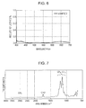
- the absolute reflectance is shown in Fig. 4
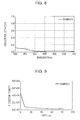
- the fluorine concentration in the depth direction of the porous layer is shown in Fig. 5 . Evaluation results are shown in Table 2.
- Example 2 an appropriate amount of chainlike SiO 2 particle coating liquid 3 was dropped onto the same oxide multilayer composite as in Example 1 and was subjected to spin coating at 3500 rpm for 20 s. Furthermore, the same fluororesin solution was applied by spin coating onto the surface of the resulting porous layer of chainlike SiO 2 particles formed on the multilayer composite in the same manner as in Example 1, and the resulting sample was heated to yield a substrate provided with an antireflection film.
- the average reflectance and the highest reflectance of the antireflection film were 0.03% and 0.11%, respectively.
- the contact angles of pure water and hexadecane on the surface of the antireflection film were 111° and 68°, respectively.
- the antireflection film had a portion having a higher fluororesin content at the surface. The portion has a thickness of 4 nm and the underlying porous layer had a thickness of 107 nm.
- the refractive index was distributed in the range of 1.244 to 1.249 from the surface.
- the atomic ratio of fluorine to silicon at the surface of the porous layer was 1.79, and the ratio of the fluorine concentration at the surface of the porous layer to the fluorine concentration at a depth of 25 nm from the surface was 7.1.
- the absolute reflectance was shown in Fig. 6 .
- Example 3 a porous layer of chainlike SiO 2 particles was formed on a multilayer composite having the same structure as in Example 1 in the same manner as in Example 1. Then, an appropriate amount of a solution of the fluororesin in a different solvent from in Example 1, Durasurf DS-1101 TH (produced by Harves, solids content: 0.04% by mass), was dropped onto the surface of the porous layer of chainlike SiO 2 particles formed on the multilayer composite. The solution was subjected to spin coating at 5000 rpm for 20 s. The resulting sample was heated at 140°C for 30 minutes in a hot air circulation oven to yield a substrate provided with an antireflection film.
- Durasurf DS-1101 TH produced by Harves, solids content: 0.04% by mass
- the average reflectance and the highest reflectance of the antireflection film were 0.03% and 0.10%, respectively.
- the contact angles of pure water and hexadecane on the surface of the antireflection film were 112° and 67°, respectively.
- the antireflection film had a portion having a higher fluororesin content at the surface. The portion has a thickness of 3 nm and the underlying porous layer had a thickness of 111 nm.
- the refractive index was distributed in the range of 1.245 to 1.250 from the surface.
- the atomic ratio of fluorine to silicon at the surface of the porous layer was 1.80, and the ratio of the fluorine concentration at the surface of the porous layer to the fluorine concentration at a depth of 25 nm from the surface was 6.5.
- Example 4 an appropriate amount of chainlike SiO 2 particle coating liquid 3 was dropped onto a substrate having the same oxide multilayer composite as in Example 1 and was subjected to spin coating at 3200 rpm for 20 s to yield a porous layer of chainlike SiO 2 particles on the substrate. Then, the same fluororesin solution as in Example 3 was sprayed for 1 s with an atomizer having a nozzle diameter of 1 mm at a pressure of 0.2 MPa. The resulting sample was heated at 140°C for 30 minutes in a hot air circulation oven to yield a substrate provided with an antireflection film.
- the average reflectance and the highest reflectance of the antireflection film were 0.02% and 0.11%, respectively.
- the contact angles of pure water and hexadecane on the surface of the antireflection film were 112° and 68°, respectively.
- the antireflection film had a portion having a higher fluororesin content at the surface. The portion has a thickness of 5 nm and the underlying porous layer had a thickness of 104 nm.
- the refractive index was distributed in the range of 1.245 to 1.250 from the surface.
- the atomic ratio of fluorine to silicon at the surface of the porous layer was 1.88, and the ratio of the fluorine concentration at the surface of the porous layer to the fluorine concentration at a depth of 25 nm from the surface was 5.4.
- Example 5 a porous layer of chainlike SiO 2 particles was formed on a multilayer composite having the same structure as in Example 1 in the same manner as in Example 1. Then, an appropriate amount of a solution of an acrylic fluororesin having a structure similar to the fluororesin used in Example 1 and exhibiting the infrared reflection spectrum shown in Fig. 7 , Durasurf DS-16005CH (produced by Harves, solids content: 0.05% by mass), was dropped onto the surface of the porous layer of chainlike SiO 2 particles formed on the multilayer composite and was subjected to spin coating at 3000 rpm for 20 s. The resulting sample was heated at 140°C for 30 minutes in a hot air circulation oven to yield a substrate provided with an antireflection film.
- Durasurf DS-16005CH produced by Harves, solids content: 0.05% by mass
- the average reflectance and the highest reflectance of the antireflection film were 0.04% and 0.13%, respectively.
- the contact angles of pure water and hexadecane on the surface of the antireflection film were 113° and 73°, respectively.
- the antireflection film had a portion having a higher fluororesin content at the surface. The portion has a thickness of 6 nm and the underlying porous layer had a thickness of 110 nm.
- the refractive index was distributed in the range of 1.245 to 1.250 from the surface.
- the atomic ratio of fluorine to silicon at the surface of the porous layer was 1.13, and the ratio of the fluorine concentration at the surface of the porous layer to the fluorine concentration at a depth of 25 nm from the surface was 8.0.
- the absolute reflectance is shown in Fig. 8
- the fluorine concentration in the depth direction of the porous layer is shown in Fig. 9 .
- Example 6 a porous layer of chainlike SiO 2 particles was formed on a multilayer composite having the same structure as in Example 1 in the same manner as in Example 1. Then, a solution of an acrylic fluororesin having a fluorocarbon group and exhibiting the infrared reflection spectrum shown in Fig. 10 , SFCOAT SNF-B200A (produced by AGC Seimi Chemical, solids content: 1% by mass), was diluted 10 times with m-xylene hexafluoride. An appropriate amount of the diluted solution was dropped onto the surface of the porous layer of chainlike SiO 2 particles formed on the multilayer composite and was subjected to spin coating at 3000 rpm for 20 s. The resulting sample was heated at 140°C for 30 minutes in a hot air circulation oven to yield a substrate provided with an antireflection film.
- an acrylic fluororesin having a fluorocarbon group and exhibiting the infrared reflection spectrum shown in Fig. 10 SFCOAT SNF-B200A (produced by
- the average reflectance and the highest reflectance of the antireflection film were 0.04% and 0.14%, respectively.
- the contact angles of pure water and hexadecane on the surface of the antireflection film were 110° and 70°, respectively.
- the antireflection film had a portion having a higher fluororesin content at the surface. The portion has a thickness of 4 nm and the underlying porous layer had a thickness of 111 nm.
- the refractive index was distributed in the range of 1.245 to 1.250 from the surface.
- the atomic ratio of fluorine to silicon at the surface of the porous layer was 1.20, and the ratio of the fluorine concentration at the surface of the porous layer to the fluorine concentration at a depth of 25 nm from the surface was 6.8.
- Table 1 shows the thicknesses and the refractive indices of the layers defining the oxide multilayer composite.
- a solution of a fluororesin having a fluorocarbon group and exhibiting the infrared reflection spectrum shown in Fig. 11 , Novec(TM) 2702 (produced by 3M, solids content: 2% by mass) was diluted 20 times with a fluorine-based solvent Novec(TM) 7300 (produced by 3M).
- the average reflectance and the highest reflectance of the antireflection film were 0.03% and 0.13%, respectively.
- the contact angles of pure water and hexadecane on the surface of the antireflection film were 114° and 63°, respectively.
- the antireflection film had a portion having a higher fluororesin content at the surface. The portion has a thickness of 4 nm and the underlying porous layer had a thickness of 110 nm.
- the refractive index was distributed in the range of 1.240 to 1.245 from the surface.
- the atomic ratio of fluorine to silicon at the surface of the porous layer was 1.37, and the ratio of the fluorine concentration at the surface of the porous layer to the fluorine concentration at a depth of 25 nm from the surface was 8.1.
- the absolute reflectance is shown in Fig. 12
- the fluorine concentration in the depth direction of the porous layer is shown in Fig. 13 .
- Example 8 a porous layer of chainlike SiO 2 particles was formed on a multilayer composite having the same structure as in Example 1 in the same manner as in Example 7. Then, an appropriate amount of a solution (solids content: 0.15% by mass) of an amorphous tetrafluoroethylene copolymer Teflon(TM) AF 1600 (produced by DuPont Mitsui Fluorochemical) shown in Fig. 14 in a fluorine-based solvent Vertrel(TM) Suprion (produced by DuPont Mitsui Fluorochemical) was dropped onto the surface of the porous layer of chainlike SiO 2 particles formed on the multilayer composite and was subjected to spin coating at 4000 rpm for 20 s. The resulting sample was heated at 140°C for 30 minutes in a hot air circulation oven to yield a substrate provided with an antireflection film.
- TM amorphous tetrafluoroethylene copolymer
- Vertrel(TM) Suprion produced by DuPont Mit
- the average reflectance and the highest reflectance of the antireflection film were 0.04% and 0.15%, respectively.
- the contact angles of pure water and hexadecane on the surface of the antireflection film were 108° and 62°, respectively.
- the antireflection film had a portion having a higher fluororesin content at the surface. The portion has a thickness of 6 nm and the underlying porous layer had a thickness of 110 nm.
- the refractive index was distributed in the range of 1.241 to 1.246 from the surface.
- the atomic ratio of fluorine to silicon at the surface of the porous layer was 2.51, and the ratio of the fluorine concentration at the surface of the porous layer to the fluorine concentration at a depth of 25 nm from the surface was 5.9.
- the absolute reflectance is shown in Fig. 15
- the fluorine concentration in the depth direction of the porous layer is shown in Fig. 16 .
- Comparative Example 1 a porous layer of chainlike SiO 2 particles was formed on a multilayer composite having the same structure as in Example 1 in the same manner as in Example 1.
- the average reflectance and the highest reflectance of the resulting antireflection film were 0.07% and 0.18%, respectively.
- the contact angles of pure water and hexadecane on the surface of the antireflection film were each 10° or less.
- the porous layer defining the surface layer had a thickness of 111 nm, and the refractive index thereof was 1.240 without being distributed.
- the atomic ratio of fluorine to silicon at the surface of the porous layer was over 100, and the ratio of the fluorine concentration at the surface of the porous layer to the fluorine concentration at a depth of 25 nm from the surface was less than 0.1.
- the absolute reflectance is shown in Fig. 17
- the fluorine concentration in the depth direction of the porous layer is shown in Fig. 18 .
- Comparative Example 2 a porous layer of chainlike SiO 2 particles was formed on a multilayer composite having the same structure as in Example 1 in the same manner as in Example 2.
- the average reflectance and the highest reflectance of the resulting antireflection film were 0.10% and 0.16%, respectively.
- the contact angles of pure water and hexadecane on the surface of the antireflection film were each 10° or less.
- the porous layer defining the surface layer had a thickness of 106 nm, and the refractive index thereof was 1.239 without being distributed.
- the atomic ratio of fluorine to silicon at the surface of the porous layer was over 100, and the ratio of the fluorine concentration at the surface of the porous layer to the fluorine concentration at a depth of 25 nm from the surface was less than 0.1.
- the absolute reflectance is shown in Fig. 19 .
- Comparative Example 3 a porous layer of chainlike SiO 2 particles was formed on a multilayer composite having the same structure as in Example 1 in the same manner as in Example 1. Then, an appropriate amount of a silane coupling agent having a fluorocarbon group, Durasurf DS-5201 S135 (produced by Harves, solids content: 0.10% by mass), was dropped onto the surface of the porous layer of chainlike SiO 2 particles formed on the multilayer composite and was subjected to spin coating at 3000 rpm for 20 s. The resulting sample was heated at 140°C for 30 minutes in a hot air circulation oven to yield a substrate provided with an antireflection film.
- a silane coupling agent having a fluorocarbon group Durasurf DS-5201 S135
- the average reflectance and the highest reflectance of the antireflection film were 0.08% and 0.18%, respectively.
- the contact angles of pure water and hexadecane on the surface of the antireflection film were 105° and 46°, respectively.
- the antireflection film had a portion having a higher fluororesin content at the surface.
- the portion has a thickness of 12 nm and the underlying porous layer had a thickness of 100 nm.
- the refractive index was 1.261 without being distributed.
- the atomic ratio of fluorine to silicon at the surface of the porous layer was 0.45, and the ratio of the fluorine concentration at the surface of the porous layer to the fluorine concentration at a depth of 25 nm from the surface was 3.7.
- the portion having a higher fluororesin content is not considered to be sufficient to reduce the reflectance and exhibit oil repellency.
- the absolute reflectance is shown in Fig. 20
- the fluorine concentration in the depth direction of the porous layer is shown in Fig. 21 .
- Table 1 shows the thicknesses and the refractive indices of the layers defining the oxide multilayer composite.
- the same fluororesin solution as in Example 1 was applied by spin coating onto the surface of the resulting porous layer of mixed SiO 2 particles formed on the multilayer composite in the same manner as in Example 1, and the resulting sample was heated to yield a substrate provided with an antireflection film.
- the average reflectance and the highest reflectance of the antireflection film were 0.21% and 0.30%, respectively.
- the contact angles of pure water and hexadecane on the surface of the antireflection film were 109° and 66°, respectively.
- the antireflection film had a portion having a higher fluororesin content at the surface. The portion has a thickness of 6 nm and the porous layer had a thickness of 106 nm.
- the refractive index was 1.302 without being distributed.
- the atomic ratio of fluorine to silicon at the surface of the porous layer was 3.1, and the ratio of the fluorine concentration at the surface of the porous layer to the fluorine concentration at a depth of 25 nm from the surface was 23.2. Since the content of chainlike SiO 2 particles in the porous layer is low, fluorine was concentrated at the surface. Consequently, the reflectance was not reduced effectively.
- the optical members of Examples 1 to 4 exhibited average reflectances of 0.05 or less, thus exhibited satisfactory antireflection effect. Also, the contact angles of pure water and hexadecane were 110° or more and 60° or more, respectively, and thus these Examples exhibited a high antifouling property. On the other hand, the optical members of Comparative Examples 1 and 2, which were not provided with fluororesin on the surface thereof, were inferior in antireflection effect to Examples 1 to 4, and the contact angles of pure water and hexadecane were as low as less than 10°.
- the optical member according to the first embodiment can be used in, for example, imaging apparatuses, such as cameras and video cameras, and optical scanning apparatuses, such as liquid crystal projectors and electrophotographic apparatuses.
- the optical member of the first embodiment has good optical properties and antifouling property.
- Fig. 24 is a schematic view of an optical member according to an embodiment of the present disclosure.
- the optical member 11 of the second embodiment includes a substrate 12, and an antireflection film 14 having a porous layer 13 on the substrate 12.
- the porous layer 13 contains silicon oxide particles 15 and a binder 16.
- the silicon oxide particles 15 are bound to each other with the binder 16.
- the surfaces of at least part of the silicon oxide particles in the vicinity of the surface of the porous layer 13 are alkylsilylated, and the surface of the porous layer 13 is defined by alkylsilylated silicon oxide particles 17.
- the porous layer 13 is provided with a fluororesin 18 thereon.
- the silicon oxide particles 15 may be in contact with each other or may be indirectly bound to each other with the binder therebetween.
- the silicon oxide particles 15 are in contact with each other from the viewpoint of enhancing wear resistance of the porous layer 13.
- Fig. 25 is a schematic view of a modification of the optical member 11 according to the present embodiment.
- the antireflection film 14 further includes an oxide layer 19 disposed between the substrate 12 and the porous layer 13.
- the oxide layer 19 has a multilayer structure including a high refractive index layer and a low refractive index layer.
- the high refractive index layer may contain zirconium oxide, titanium oxide, tantalum oxide, niobium oxide, or hafnium oxide.
- the low refractive index layer may contain silicon oxide or magnesium fluoride.
- the optical member of the second embodiment may be used for optical lenses, optical mirrors, filters, or optical films.
- the optical member is particularly suitable for optical lenses.
- the substrate 12 may be made of glass or a resin. Also, the substrate 12 has any shape without particular limitation and may have a flat, curved, or recessed surface or may be in the form of a film.
- the average particle size of the silicon oxide particles 15 is in the range of 10 nm to 80 nm, more desirably in the range of 12 nm to 60 nm. If the average particle size of the silicon oxide particles 15 is less than 10 nm, the pores among the particles and in the particles can be so small that the refractive index cannot be reduced. In contrast, if the average particle size exceeds 80 nm, large pores are formed among the particles, and accordingly, a large void is likely to be formed. In addition, such large particles disadvantageously cause scattering.
- the average particle size of silicon oxide particles mentioned herein refers to an average Feret diameter.
- the average Feret diameter can be determined by image processing of transmission electron micrographs.
- image processing a commercially available image processing apparatus, such as image Pro PLUS (manufactured by Media Cybernetics), may be used. More specifically, Feret diameters of particles in a specific image region, whose contrast may be adjusted if necessary, are measured and averaged.
- the silicon oxide particles 15 may be in the shape of circle, oval, disk, bar, needle, chain, or square and may be hollow particles having holes inside.
- the percentage of hollow or chain silicon oxide particles account for 50% by mass or more, desirably 80% by mass or more, of the silicon oxide particles 15.
- the refractive index of the porous layer 13 can be reduced by increasing the porosity.
- a hollow silicon oxide particle used herein refers to a particle having a hole defined by a shell of silicon oxide.
- the presence of air (having a refractive index of 1.0) in the hole reduces the refractive index of the porous layer 13 to be lower than the refractive index in the case of silicon oxide particles not having holes.
- the number of holes may be one or more and may be determined as needed.
- the thickness of the shell defining the hole of the hollow particle may be in the range of 10% to 50%, desirably in the range of 20% to 35%, of the average particle size. If the thickness is less than 10%, the strength of the particles is insufficient. In contrast, if the thickness of the shell exceeds 50%, the refractive index is not reduced effectively.
- a chainlike particle is a chain or string formed of a plurality of particles.
- Chainlike silicon oxide particles maintain the form of a chain or string even after being formed into a film. Therefore, the use of chainlike silicon oxide particles can increase the porosity compared to the case of using discrete particles.
- particles forming a chain can each be small and are not likely to form a void.
- the number of particles forming a chainlike particle is in the range of 2 to 10 and is advantageously in the range of 3 to 6. If the number of particles forming a chain exceeds 10, a void is likely to be formed, and accordingly the wear resistance of the layer is degraded.
- the particle size of particles having a minor and a major axis like chainlike particles is defined by the minor axis.
- the silicon oxide particles 15 mainly contain SiO 2 , and the Si accounts for desirably 80 atomic percent or more, more desirably 90 atomic percent or more, of all the elements in the chainlike silicon oxide particles except oxygen. If the Si content is less than 80 atomic percent, silanol (Si-OH) groups at the surfaces of the particles, which will react with the binder 16 are reduced, and consequently, the wear resistance of the resulting layer is degraded.
- Si-OH silanol
- SiO 2 In addition to SiO 2 , another metal oxide such as Al 2 O 3 , TiO 2 , ZnO 2 , or ZrO 2 , or an organic component such as an alkyl group or an alkyl fluoride group may be introduced into the silicon oxide particles 15 or to the surfaces of the silicon oxide particles.
- another metal oxide such as Al 2 O 3 , TiO 2 , ZnO 2 , or ZrO 2 , or an organic component such as an alkyl group or an alkyl fluoride group may be introduced into the silicon oxide particles 15 or to the surfaces of the silicon oxide particles.
- hydrophilic particles whose silanol groups on the surfaces thereof remain 70% or more. More advantageously, silanol groups remains 90% or more on the surfaces of the particles. If the silanol groups on the surfaces of the particles are reduced to less than 70% by surface modification with organic groups, the hydrophilicity of the particles is lost.
- the interaction and reactivity between the particles and the binder are reduced, and accordingly, the strength of the resulting layer is reduced.
- the silicon oxide particles in the vicinity of the surface of the porous layer 13 are modified into alkylsilylated silicon oxide particles 17, the hydrophilicity of the other silicon oxide particles 15 is maintained. Thus, the strength of the resulting layer is unlikely to decrease.
- R1 represents a hydrogen atom or a monovalent organic group selected from the group consisting of linear or branched alkyl groups having a carbon number of 1 to 8, alkenyl groups, and fluorinated alkyl groups.
- R2 represents a monovalent organic group selected from the group consisting of linear or branched alkyl group having a carbon number of 1 to 8, alkenyl groups, and fluorinated alkyl groups.
- Alkylsilyl groups may be used singly or in combination.
- the content of the silicon oxide particles 15 in the porous layer 3 is desirably in the range of 50% by mass to 95% by mass, such as in the range of 65% by mass to 85% by mass.
- the binder 16 may be selected according to the wear resistance, adhesion and environmental reliability of the antireflection film. Silicon oxide binders are advantageous because they have affinity with the silicon oxide particles 15 and can increase the wear resistance of the porous layer 13. A hydrolysis-condensation product of silicate is particularly advantageous among the silicon oxide binders.
- the silicon oxide binder has a polystyrene-equivalent weight average molecular weight in the range of 500 to 3000. If the weight average molecular weight is less than 500, the cured porous layer tends to be cracked, or the stability of the binder solution or liquid to be applied is degraded. In contrast, if the weight average molecular weight exceeds 3000, the viscosity of the binder is increased. Consequently, nonuniform voids are likely to be formed in the binder phase and, accordingly, large voids are likely to be formed.
- the content of the binder 16 in the porous layer 13 is desirably in the range of 5% by mass to 40% by mass, such as in the range of 10% by mass to 30% by mass.
- the silicon oxide binder is represented by the following composition formula (4):
- R3 represents a group selected from the group consisting of alkyl having a carbon number of 1 to 8, alkenyl, alkynyl, and aromatic rings, and these groups may have a substituent of an amino, an isocyanate, a mercapto, or an acryloyl group or a halogen atom.
- m satisfies 0.90 ⁇ m ⁇ 0.99.
- m in formula (4) is less than 0.9, the hydrophilicity of the binder 6 is reduced. Consequently, the interaction between the binder 6 and the silicon oxide particles 5 is weakened, and the wear resistance of the porous layer 13 is degraded. Desirably, 0.95 ⁇ m ⁇ 0.99 holds true.
- the surface of the binder 16 bound to the alkylsilylated silicon oxide particles 17 may be alkylsilylated. If a silicon oxide binder is used, it is advantageous that the binder phase contains silanol groups. The silanol groups in the binder 16 form hydrogen bonds, thus increasing the wear resistance of the porous layer 13. Fluororesin
- fluororesin 18 examples include perfluoropolyether, polytetrafluoroethylene (PTFE), poly(vinylidene fluoride) (PVDF), perfluoroalkoxy resin (PFA), and copolymers of tetrafluoroethylene and hexafluoropropylene.
- Polymers such as acrylic resin and vinyl resin, having a fluorocarbon group, such as a fluoroalkyl group or a fluoroalkenyl group, as a pendant group may be used as the fluororesin. It is difficult to form a very thin uniform oil-repellent layer on an uneven or porous surface like the surface of the porous layer 3. Fluororesin can exhibit oil repellency even though it is not in the form of an even layer.
- the porous layer 13 may have a thickness in the range of 80 nm to 200 nm, desirably in the range of 100 nm to 160 nm.
- a porous layer of less than 80 nm in thickness is unlikely to exhibit good wear resistance, and a porous layer of larger than 200 nm in thickness is unlikely to have a reduced reflectance.
- the porosity of the porous layer 13 is desirably in the range of 30% to 50%.
- a porous layer having a porosity of less than 30% exhibits a high refractive index and may not produce an antireflection effect, and a porous layer having a porosity of higher than 50% is inferior in wear resistance because of the presence of excessively large pores.
- the refractive index of the porous layer 13 is desirably in the range of 1.19 to 1.35, such as in the range of 1.22 to 1.32.
- the silicon oxide particles in the vicinity of the surface of the porous layer 13 are modified into alkylsilylated silicon oxide particles 17 by substitution of alkylsilyl groups for the hydrogen atoms of the silanol groups on the surfaces of the silicon oxide particles.
- a porous layer is provided with a fluororesin 18 thereon. If oil or the like is attached to a porous layer 13 not provided with the fluororesin 18, the oil or the like is likely to penetrate and diffuse into the pores among the silicon oxide particles. The same applied to the oil component in dust or the like. The oil component in dust attached to the porous layer, even though it is not visible, can penetrate and diffuse into the pores among the silicon oxide particles after a time has passed.
- the refractive index of the portion to which the oil component has diffused is varied, and thus a visible defect appears in the resulting optical member.
- the oil repellency of the fluororesin 18 prevents oil or any other dirt from penetrating and diffusing.
- the fluororesin 18 Since it is difficult to form a very thin uniform fluorocarbon film on the porous layer 13, as described above, the fluororesin 18 is applied in an island manner or a dotted matter, or in the form of an uneven layer including thick portions and thin portions.
- it is attempted to remove the oil with a solvent the oil is dissolved in the solvent and the viscosity of the oil component is reduced.
- the oil component having a reduced viscosity is likely to reach the porous layer 13 through the gaps in the coating of the fluororesin 18.
- the porous layer 13 is easily contaminated with organic substances due to the high activity of silanol groups unless the silicon oxide particles in the vicinity of the surface of the porous layer 13 are alkylsilylated. Therefore, the oil component dissolved in a solvent that has reached the porous layer 13 through the gaps in the coating of the fluororesin 18 penetrates and diffuses deeply into the porous layer 13. Then, the solvent is removed by volatilization, and thus the remaining oil component turns visible. This is a cause of defects in terms of optical properties and appearance. If the silicon oxide particles in the vicinity of the surface of the porous layer 13 are modified into alkylsilylated silicon oxide particles 17, the surface of the porous layer 13 hardly has silanol groups that help the penetration and diffusion of oil.
- the contact angle of hexadecane on the surface of the porous layer 13 is in the range of 50° to 80°, more advantageously in the range of 60° to 75°.
- the contact angle of hexadecane mentioned herein refers to the contact angle of 10 ⁇ L of hexadecane dropped on the surface of an antireflection film, measured by a half-angle method ( ⁇ /2 method). If the contact angle of hexadecane is less than 50°, oil is not sufficiently prevented from diffusing.
- the contact angle of water with the surface of the porous layer 13 is in the range of 100° to 130°, more advantageously in the range of 110° to 120°.
- the increment of the refractive index of the entire porous layer 13 increased by applying fluororesin is desirably in the range of 0.0075 to 0.02, such as in the range of 0.01 to 0.02. If the increment of the refractive index is less than 0.0075, the contact angle of hexadecane is undesirably reduced to less than 50°. If the increment of the refractive index exceeds 0.02, the surface of the porous layer 13 undesirably has a portion having a high refractive index.
- the increment of the refractive index of the entire porous layer 13 increased by alkylsilylation is desirably in the range of 0.001 to 0.008, such as in the range of 0.002 to 0.005. If the increment of the refractive index increased by alkylsilylation is less than 0.001, the silicon oxide particles are not sufficiently modified into alkylsilylated silicon oxide particles 17, and accordingly a mark formed by wiping dirt off is likely to be left. If the increment of the refractive index exceeds 0.008, fluorine is unlikely to be attached to the surface of the porous layer 13, and accordingly, the contact angle of hexadecane is undesirably reduced to less than 50°.
- a method for manufacturing the optical member 11 according to the present embodiment includes forming the porous layer 13, in which the silicon oxide particles 15 are bound to each other with the binder 16, on the surface of a substrate 12 or the surface of a layer or a multilayer structure disposed on the substrate 12.
- a dry process or a wet process may be employed.
- the wet process allows the porous layer 13 to be easily formed and is thus advantageous.
- a dispersion liquid of the silicon oxide particles and a binder solution may be separately applied one after the other, or a dispersion liquid containing both the silicon oxide particles and the binder may be applied.
- the dispersion liquid of the silicon oxide particles is prepared by dispersing the silicon oxide particles in a solvent.
- the silicon oxide content in this dispersion liquid is desirably in the range of 2% by mass to 10% by mass.
- the dispersion liquid of the silicon oxide particles 15 may further contain a silane coupling agent or a surfactant for increasing dispersibility.
- a silane coupling agent or a surfactant for increasing dispersibility.
- the proportion of the additive such as a silane coupling agent or a surfactant is desirably 10 parts by mass or less, more desirably 5 parts by mass or less, relative to 100 parts by mass of the silicon oxide particles.
- a silicon oxide binder solution is used as the binder solution.
- Silicon oxide binders have a strong binding force with the silicon oxide particles.
- the silicon oxide binder solution mainly contains a hydrolysis-condensation product of silicate.
- This solution may be prepared by adding water and an acid or a base to a silicate ester, such as methyl silicate or ethyl silicate, in a solvent for hydrolysis and condensation.
- the acid used for this reaction may be hydrochloric acid, nitric acid, or the like, and the base may be ammonia or an amine. These are selected in view of solubility in the solvent and reactivity with the silicate ester.
- the silicon oxide binder solution may be prepared by neutralizing a silicate such as sodium silicate in water for condensation and then diluting the condensate with a solvent.
- the acid used for the neutralization may be hydrochloric acid, nitric acid, or the like.
- the binder solution may be prepared while being heated to a temperature of 80°C or less.
- a trifunctional silane alkoxide substituted by an organic group such as methyltriethoxysilane or ethyltriethoxysilane, may be added for improving solubility and ease of application.
- the proportion of the trifunctional silane alkoxide is desirably 10% by mole or less to the total moles of silane alkoxides. If the amount of the trifunctional silane alkoxide added exceeds 10% by mole, the organic groups in the binder hinder the silanol groups from forming hydrogen bonds in the binder, and consequently, the wear resistance of the porous layer is degraded.
- the silicon oxide content in the silicon oxide binder solution is desirably in the range of 0.2% by mass to 2% by mass.
- the dispersion liquid may be prepared by mixing a dispersion liquid of the silicon oxide particles and a solution of the binder, or adding the material of the binder into a dispersion liquid of the silicon oxide particles.
- the dispersion liquid may be prepared through a reaction performed by adding ethyl silicate, water, and an acid catalyst into the dispersion liquid of silicon oxide particles. It is advantageous to prepare a binder solution in advance because the dispersion liquid can be prepared while the state of the reaction is being checked.
- the proportion of the binder in the dispersion liquid containing both the silicon oxide particles and the silicon oxide binder is desirably in the range of 5 parts by mass to 35 parts by mass, such as 10 parts by mass to 20 parts by mass, relative to 100 parts by mass of the silicon oxide particles.
- the solvents for the dispersion liquid of the silicon oxide particles and the silicon oxide binder solution are such that they can uniformly disperse or dissolve the material and does not allow the reaction product to precipitate.
- Such solvents include monohydric alcohols, such as methanol, ethanol, 1-propanol, 2-propanol, 1-butanol, 2-butanol, 2-methylpropanol, 1-pentanol, 2-pentanol, cyclopentanol, 2-methylbutanol, 3-methylbutanol, 1-hexanol, 2-hexanol, 3-hexanol, 4-methyl-2-pentanol, 2-methyl-1-pentanol, 2-ethylbutanol, 2,4-dimethyl-3-pentanol, 3-ethylbutanol, 1-heptanol, 2-heptanol, 1-octanol, and 2-octanol; dihydric alcohols, such as ethylene glycol and tri
- the dispersion liquid of the silicon oxide particles 15 and the solution of the binder 16 or the mixture thereof is applied by, for example, spin coating, blade coating, roll coating, slit coating, printing, or dip coating. If an optical member having recesses or any other three-dimensional complex shape is manufactured, spin coating is advantageous from the viewpoint of forming a uniform thickness.
- the layer is dried and/or cured.
- This drying and/or curing operation is intended to remove the solvent or to promote the reaction between the silicon oxide binder molecules or between the silicon oxide binder and the silicon oxide particles.
- This operation may be performed at a temperature in the range of 20°C to 200°C, desirably in the range of 60°C to 150°C. If the temperature for drying and/or curing is less than 20°C, the solvent remains in the porous layer and the wear resistance will be reduced. If the temperature for drying or curing exceeds 200°C, the binder will be excessively cured to the extent that it will be likely to be cracked.
- the time period for drying or curing is desirably in the range of 5 minutes to 24 hours, such as 15 minutes to 5 hours. If the drying or curing time is less than 5 minutes, part of the solvent will remain. Consequently, the in-plane variation in refractive index can be increased. In contrast, if the drying or curing time exceeds 24 hours, the binder will be likely to be cracked.
- the coating of the dispersion liquid may be dried and/or fired.
- a solution of the fluororesin is applied by, for example, spin coating, blade coating, roll coating, slit coating, printing, or dip coating.
- the solvent of the fluororesin solution desirably has a high compatibility in view of oil repellency.
- the solvent used in the fluororesin solution include hydrofluoroether, perfluorocarbon, and a mixture thereof.
- the fluororesin content in the solution may be in the range of 0.04% by mass to 0.1% by mass.
- an alkylsilazane compound is suitably used for alkylsilylation. More specifically, the porous layer 13 may be exposed to an atmosphere containing an alkylsilazane compound, or a solution of an alkylsilazane compound in a solvent may be applied onto the porous layer 13.
- the silazane bond (Si-N) of alkylsilazane compounds is reactive.
- the alkylsilazane compound reacts with the silanol groups (Si-OH) on the surfaces of the silicon oxide particles to form Si-O-Si bonds.
- Si-OH silanol groups
- alkylsilazane compound examples include (dimethylamino)trimethylsilane, (diethylamino)trimethylsilane, butyldimethyl(dimethylamino)silane, octyldimethyl(dimethylamino)silane, diphenylmethyl(dimethylamino)silane, N-methyl-N-trimethylsilylacetamide, N-methyl-N-trimethylsilyltrifluoroacetamide, N-trimethylsilylacetamide, N-trimethylsilylimidazole, 1,1,1,3,3,3-hexamethyldisilazane, 1,1,3,3-tetramethyldisilazane, 1,3-divinyl-1,1,3,3-tetramethyldisilazane, 1,3-dipropyl-1,1,3,3-tetra methyldisilazane, 1,3-dibutyl-1,1,
- Alkylsilazane compounds represented by the following formulas (5), (6), and (7) are advantageous because these compound are more reactive than other alkylsilazane compounds and less likely to remain as unreacted matter.
- R4 represents a hydrogen atom or a monovalent organic group selected from the group consisting of linear or branched alkyl groups having a carbon number of 1 to 8, alkenyl groups, and fluorinated alkyl groups.
- R5 and R6 each represent a species selected from the group consisting of a hydrogen atom, alkyl groups having a carbon number of 1 to 3, an acetyl group, and a trifluoroacetyl group, or form an imidazoline ring together.
- R7 represents a hydrogen atom or a monovalent organic group selected from the group consisting of linear or branched alkyl groups having a carbon number of 1 to 8, alkenyl groups, and fluorinated alkyl groups
- R8 represents a hydrogen atom or an alkyl group having a carbon number of 1 to 3.
- R9 and R10 each represent a monovalent organic group selected from the group consisting of linear or branched alkyl group having a carbon number of 1 to 8, alkenyl groups, and fluorinated alkyl groups, and R11 represents a methyl group or a trifluoromethyl group.
- alkylsilazane compounds of the above formulas include (dimethylamino)trimethylsilane, (diethylamino)trimethylsilane, N-methyl-N-trimethylsilylacetamide, N-methyl-N-trimethylsilyltrifluoroacetamide, N-trimethylsilylacetamide, N-trimethylsilylimidazole, 1,1,1,3,3,3-hexamethyldisilazane, 1,3-divinyl-1,1,3,3-tetramethyldisilazane, 1,3-dipropyl-1,1,3,3-tetramethyldisilazane, 1,3-bis(3,3,3-trifluoropropyl)-1,1,3,3-tetramethyldisilazane, N,O-bis(trimethylsilyl)acetamide, and N,O-bis(trimethylsilyl)trifluoroacetamide.
- Alkylsilazane compounds represented by the following formulas (8) and (9) are advantageous in terms of bifunctionality and water repellency.
- R12 represents a monovalent organic group selected from the group consisting of linear or branched alkyl groups having a carbon number of 1 to 8, alkenyl groups, and fluorinated alkyl groups, and R13 and R14 each represent a hydrogen atom or an alkyl group having a carbon number of 1 to 3.
- R15 represents a monovalent organic group selected from the group consisting of linear or branched alkyl groups having a carbon number of 1 to 8, alkenyl groups, and fluorinated alkyl groups
- R16 represents a hydrogen atom or an alkyl group having a carbon number of 1 to 3.
- m is an integer of 3 or 4.
- alkylsilazane compounds of formulas (8) and (9) include bis(dimethylamino)dimethylsilane, bis(diethylamino)dimethylsilane, dimethylbis(s-butylamino)silane, 2,2,4,4,6,6-hexamethylcyclotrisilazane, and 2,4,6-trimethyl-2,4,6-trivinylcyclotrisilazane.
- a gas containing the alkylsilazane compound may be sprayed onto the porous layer 13, or a gas containing the alkylsilazane compound and the porous layer 13 may be confined together in a container.
- a mixed gas containing an alkylsilazane compound and the porous layer 13 are confined together in a container.
- This treatment can be performed with a small amount of alkylsilazane compound.
- This treatment in the container may be performed under atmospheric pressure or reduced pressure. In view of convenience, treatment under atmospheric pressure is advantageous.
- the concentration of the alkylsilazane compound in the mixed gas is advantageously in the range of 5 mg/L to 200 mg/L.
- the temperature of the atmosphere containing an alkylsilazane compound to which the porous layer 13 is exposed is desirably in the range of 10°C to 60°C, such as in the range of 20°C to 40°C. If the temperature of this atmosphere is less than 10°C, the alkylsilazane compound may not sufficiently impart water repellency to the surface of the porous layer 13. If the temperature exceeds 60°C, the alkylsilazane compound can swell the porous layer 13.
- the exposure time to the atmosphere containing an alkylsilazane compound is desirably in the range of 0.5 hour to 5 hours, such as in the range of 1 hour to 3 hours. If the exposure time is less than 0.5 hour, the silicon oxide particles are not sufficiently alkylsilylated, and accordingly dirt can diffuse. If the exposure time exceeds 5 hours, the porous layer 13 is entirely alkylsilylated, and thus the refractive index can be excessively increased.
- the excess alkylsilazane compound in the layer may be removed. If the alkylsilazane compound is volatile, the excess alkylsilazane compound can be removed by simply allowing the porous layer 13 to stand in an atmosphere not containing any alkylsilazane compound. If the volatility of the alkylsilazane compound is low, the alkylsilazane compound may be removed by heating or decompression. If the alkylsilazane compound is removed by heating, the heating temperature may be in the range of 40°C to 150°C. Alternatively, the excess alkylsilazane compound may be washed away with a solvent. In this instance, a volatile solvent, such as methanol, ethanol, or acetone, is advantageously used.
- a volatile solvent such as methanol, ethanol, or acetone
- a solution prepared by uniformly dissolving an alkylsilazane compound in a solvent can be applied onto the porous layer 13.
- the solvent of the alkylsilazane compound is desirably an aprotic solvent.
- the aprotic solvent include ethers, such as dimethoxyethane, Diglyme, tetrahydrofuran, dioxane, diisopropyl ether, dibutyl ether, and cyclopentyl methyl ether; esters, such as ethyl formate, ethyl acetate, n-butyl acetate, ethylene glycol monomethyl ether acetate, ethylene glycol monoethyl ether acetate, ethylene glycol monobutyl ether acetate, and propylene glycol monomethyl ether acetate; aliphatic or alicyclic hydrocarbons, such as n-hexane, n-octane, cyclohexane, cyclopentane, and cyclooctane; aromatic hydrocarbons, such as toluene, x
- aprotic solvents are advantageous dibutyl ether, cyclopentyl methyl ether, n-butyl acetate, propylene glycol monomethyl ether acetate, cyclooctane, toluene, xylene, ethylbenzene, methyl isobutyl ketone, cyclopentanone, cyclohexanone, hydrofluoro ether, perfluorocarbon, and N,N-dimethylacetamide.
- These solvents are not much hygroscopic and are easy to apply.
- a fluororesin solution containing an alkylsilazane compound may be applied.
- the proportion of the alkylsilazane compound in the solution containing both the fluororesin and the alkylsilazane compound is desirably in the range of 5 parts by mass to 1000 parts by mass, such as 10 parts by mass to 500 parts by mass, relative to 100 parts by mass of the fluororesin.
- Thickness was determined from the results of measurement with a spectroscopic ellipsometer (VASE, manufactured by J. A. Woollam) at wavelengths from 380 nm to 800 nm.
- VASE spectroscopic ellipsometer
- Refractive index was measured with a spectroscopic ellipsometer (VASE, manufactured by J. A. Woollam) at wavelengths from 380 nm to 800 nm.
- the refractive index at a wavelength of 550 nm was used for evaluation.
- the contact angle of 2 ⁇ L of pure water or hexadecane droplet on a sample was measured with a full automatic contact angle meter DM-701 (manufactured by Kyowa Interface Science).
- the contact angle of pure water was rated according to the following criteria:
- the contact angle of hexadecane was rated according to the following criteria:
- Quantera SXM manufacture by ULVAC-PHI was used.
- a monochromatic Al X-ray source was used, and the X-ray beam diameter was 100 ⁇ m.
- Spectra were obtained by scanning an area of 500 ⁇ m x 500 ⁇ m of each sample with this X-ray beam.
- the composition of the sample was analyzed in the depth direction while being etched with an argon ion gun.
- an appropriate amount of a solution of an acrylic fluororesin having a fluorinated hydrocarbon group Durasurf DS-1101 S135 (produced by Harves, solids content: 0.10% by mass), was dropped and subjected to spin coating at 3000 rpm for 20 s. Then, the sample was heated at 140°C for 30 minutes in a hot air circulation oven to form a film including a porous layer in which chainlike SiO 2 particles are bound to each other with the binder and onto which the acrylic resin having a fluorinated hydrocarbon group is attached.
- the sample having the film was placed in a 610 mL glass container together with 0.02 g an alkylsilazane compound 1,1,1,3,3,3-hexamethyldisilazane in a glass laboratory dish.
- the glass container was sealed with a propylene lid with a silicone resin gasket and allowed to stand at 23°C for 3 hours. Then, the sample having the film was removed and allowed to stand in the air for 30 minutes. All the 1,1,1,3,3,3-hexamethyldisilazane in the container was volatilized.
- the concentration of the alkylsilazane compound that had been in the container was calculated from the amount of volatilization and was 33 mg/L.
- the porous layer of the resulting optical member had a refractive index of 1.253 and a thickness of 120 nm, and the contact angles of pure water and hexadecane on the porous layer were 118° and 64°, respectively.
- the wipe-off test of the porous layer onto which hexadecane had been dropped no traces of droplets nor marks after wiping were observed.
- the variation in refractive index in the high temperature, high humidity test was as small as less than 0.01. Evaluation test results are shown in Table 3.
- an appropriate amount of a solution of an acrylic fluororesin having a fluorinated hydrocarbon group Durasurf DS-1101 S135 (produced by Harves, solids content: 0.10% by mass), was dropped and subjected to spin coating at 3000 rpm for 20 s. Then, the sample was heated at 140°C for 30 minutes in a hot air circulation oven to form a film including a porous layer in which SiO 2 hollow particles are bound to each other with the binder and onto which the acrylic fluororesin having a fluorinated hydrocarbon group is attached.
- the porous layer was subjected to alkylsilylation with 1,1,1,3,3,3-hexamethyldisilazane in the same manner as in Example 2-1.
- the porous layer of the resulting optical member had a refractive index of 1.252 and a thickness of 118 nm, and the contact angles of pure water and hexadecane on the porous layer were 116° and 65°, respectively.
- the wipe-off test of the porous layer onto which hexadecane had been dropped no traces of droplets nor marks after wiping were observed.
- the variation in refractive index in the high temperature, high humidity test was as small as less than 0.01.
- SiO 2 binder coating liquid (2-4) and the solution of the acrylic fluororesin having a fluorinated hydrocarbon group were applied in that order onto the resulting porous layer and heated to yield a film including a porous layer in which chainlike SiO 2 particles are bound to each other with the binder and onto which the acrylic fluororesin having a fluorinated
- the porous layer was subjected to alkylsilylation in the same manner as in Example 2-1, using 1,3-bis(3,3,3-trifluoropropyl)-1,1,3,3-tetramethyldisilazane as the alkylsilazane compound.
- the amount of 1,3-bis(3,3,3-trifluoropropyl)-1,1,3,3-tetramethyldisilazane volatilized for 5 hours in the container was 0.003 g.
- the concentration of the alkylsilazane compound that had been in the container was calculated from the amount of volatilization and was 5.0 mg/L.
- the porous layer of the resulting optical member had a refractive index of 1.253 and a thickness of 120 nm, and the contact angles of pure water and hexadecane on the porous layer were 116° and 64°, respectively.
- the wipe-off test of the porous layer onto which hexadecane had been dropped no traces of droplets nor marks after wiping were observed.
- the variation in refractive index in the high temperature, high humidity test was as small as less than 0.01. Evaluation test results are shown in Table 3.
- SiO 2 binder coating liquid (2-4) and the solution of an acrylic fluororesin having a fluorinated hydrocarbon group were applied in that order onto the resulting porous layer and heated to yield a film including a porous layer in which SiO 2 hollow particles are bound to each other with the binder.
- the porous layer was subjected to alkylsilylation with 1,1,1,3,3,3-hexamethyldisilazane in the same manner as in Example 2-2.
- the porous layer of the resulting optical member had a refractive index of 1.251 and a thickness of 118 nm, and the contact angles of pure water and hexadecane on the porous layer were 114° and 70°, respectively.
- the wipe-off test of the porous layer onto which hexadecane had been dropped no traces of droplets nor marks after wiping were observed.
- the variation in refractive index in the high temperature, high humidity test was as small as less than 0.01.
- SiO 4 binder coating liquid (2-4) and the solution of an acrylic fluororesin having a fluorinated hydrocarbon group were applied in that order onto the resulting porous layer and heated to yield a film including a porous layer in which chainlike SiO 2 particles are bound to each other with the binder and onto which the acrylic fluororesin having
- the porous layer of the resulting optical member had a refractive index of 1.248 and a thickness of 120 nm, and the contact angles of pure water and hexadecane on the porous layer were 111° and 67°, respectively.
- the wipe-off test of the porous layer onto which hexadecane had been dropped a mark after wiping was observed.
- the variation in refractive index in the high temperature, high humidity test was 0.03.
- the porous layer of the resulting optical member had a refractive index of 1.240 and a thickness of 117 nm, and the contact angles of pure water and hexadecane on the porous layer were each 10° or less.
- the wipe-off test of the porous layer onto which hexadecane had been dropped a mark after wiping was observed.
- the variation in refractive index in the high temperature, high humidity test was as large as over 0.04.
- the porous layer was coated with SiO 2 binder coating liquid (2-4) in the same manner as in Example 2-1.
- application of the acrylic fluororesin having a fluorinated hydrocarbon group, and alkylsilylation were simultaneously performed on the porous layer in which chainlike SiO 2 particles were bound to each other with the binder.
- the porous layer of the resulting optical member had a refractive index of 1.253 and a thickness of 120 nm, and the contact angles of pure water and hexadecane on the porous layer were 117° and 64°, respectively.
- the wipe-off test of the porous layer onto which hexadecane had been dropped no traces of droplets nor marks after wiping were observed.
- the variation in refractive index in the high temperature, high humidity test was as small as less than 0.01. Evaluation test results are shown in Table 4.
- the porous layer was coated with SiO 2 binder coating liquid (2-4) in the same manner as in Example 2-1.
- application of the acrylic fluororesin having a fluorinated hydrocarbon group, and alkylsilylation were simultaneously performed on the porous layer in which chainlike SiO 2 particles were bound to each other with the binder.
- the porous layer of the resulting optical member had a refractive index of 1.252 and a thickness of 120 nm, and the contact angles of pure water and hexadecane on the porous layer were 117° and 65°, respectively.
- the wipe-off test of the porous layer onto which hexadecane had been dropped no traces of droplets nor marks after wiping were observed.
- the variation in refractive index in the high temperature, high humidity test was as small as less than 0.01.
- the porous layer was coated with SiO 2 binder coating liquid (2-4) in the same manner as in Example 2-1.
- application of the acrylic fluororesin having a fluorinated hydrocarbon group and alkylsilylation were simultaneously performed on the porous layer in which chainlike SiO 2 particles were bound to each other with the binder.
- the porous layer of the resulting optical member had a refractive index of 1.251 and a thickness of 120 nm, and the contact angles of pure water and hexadecane on the porous layer were 113° and 69°, respectively.
- the wipe-off test of the porous layer onto which hexadecane had been dropped no traces of droplets nor marks after wiping were observed.
- the variation in refractive index in the high temperature, high humidity test was as small as less than 0.01.
- the porous layer was coated with SiO 2 binder coating liquid (2-4) in the same manner as in Example 2-2.
- application of the acrylic fluororesin having a fluorinated hydrocarbon group and alkylsilylation were simultaneously performed on the porous layer in which SiO 2 hollow particles were bound to each other with the binder.
- the porous layer of the resulting optical member had a refractive index of 1.250 and a thickness of 118 nm, and the contact angles of pure water and hexadecane on the porous layer were 115° and 65°, respectively.
- the wipe-off test of the porous layer onto which hexadecane had been dropped no traces of droplets nor marks after wiping were observed.
- the variation in refractive index in the high temperature, high humidity test was as small as less than 0.01.
- the porous layer of the resulting optical member had a refractive index of 1.343 and a thickness of 117 nm, and the contact angles of pure water and hexadecane on the porous layer were 105° and 65°, respectively.
- the wipe-off test of the porous layer onto which hexadecane had been dropped no traces of droplets nor marks after wiping were observed.
- the variation in refractive index in the high temperature, high humidity test was as small as less than 0.01.
- the porous layer was coated with SiO 2 binder coating liquid (2-4) in the same manner as in Example 2-1.
- application of the acrylic fluororesin having a fluorinated hydrocarbon group and alkylsilylation were simultaneously performed on the porous layer in which chainlike SiO 2 particles were bound to each other with the binder.
- the porous layer of the resulting optical member had a refractive index of 1.252 and a thickness of 120 nm, and the contact angles of pure water and hexadecane on the porous layer were 116° and 64°, respectively.
- the wipe-off test of the porous layer onto which hexadecane had been dropped no traces of droplets nor marks after wiping were observed.
- the variation in refractive index in the high temperature, high humidity test was as small as less than 0.01.
- the porous layer was coated with SiO 2 binder coating liquid (2-4) in the same manner as in Example 2-1.
- application of the acrylic fluororesin having a fluorinated hydrocarbon group and alkylsilylation were simultaneously performed on the porous layer in which chainlike SiO 2 particles were bound to each other with the binder.
- the porous layer of the resulting optical member had a refractive index of 1.252 and a thickness of 120 nm, and the contact angles of pure water and hexadecane on the porous layer were 117° and 65°, respectively.
- the wipe-off test of the porous layer onto which hexadecane had been dropped no traces of droplets nor marks after wiping were observed.
- the variation in refractive index in the high temperature, high humidity test was as small as less than 0.01.
- the porous layer was coated with SiO 2 binder coating liquid (2-4) in the same manner as in Example 2-1.
- application of the acrylic fluororesin having a fluorinated hydrocarbon group and alkylsilylation were simultaneously performed on the porous layer in which chainlike SiO 2 particles were bound to each other with the binder.
- the porous layer of the resulting optical member had a refractive index of 1.253 and a thickness of 120 nm, and the contact angles of pure water and hexadecane on the porous layer were 115° and 67°, respectively.
- the wipe-off test of the porous layer onto which hexadecane had been dropped no traces of droplets nor marks after wiping were observed.
- the variation in refractive index in the high temperature, high humidity test was as small as less than 0.01.
- the porous layer was coated with SiO 2 binder coating liquid (2-4) in the same manner as in Example 2-1.
- application of the acrylic fluororesin having a fluorinated hydrocarbon group and alkylsilylation were simultaneously performed on the porous layer in which chainlike SiO 2 particles were bound to each other with the binder.
- the porous layer of the resulting optical member had a refractive index of 1.251 and a thickness of 120 nm, and the contact angles of pure water and hexadecane on the porous layer were 112° and 72°, respectively.
- the wipe-off test of the porous layer onto which hexadecane had been dropped no traces of droplets nor marks after wiping were observed.
- the variation in refractive index in the high temperature, high humidity test was as small as less than 0.01.
- the porous layer was coated with SiO 2 binder coating liquid (2-4) in the same manner as in Example 2-1.
- application of the acrylic fluororesin having a fluorinated hydrocarbon group and alkylsilylation were simultaneously performed on the porous layer in which SiO 2 hollow particles were bound to each other with the binder.
- the porous layer of the resulting optical member had a refractive index of 1.251 and a thickness of 120 nm, and the contact angles of pure water and hexadecane on the porous layer were 113° and 72°, respectively.
- the wipe-off test of the porous layer onto which hexadecane had been dropped no traces of droplets nor marks after wiping were observed.
- the variation in refractive index in the high temperature, high humidity test was as small as less than 0.01.
- the porous layer was coated with SiO 2 binder coating liquid (2-4) in the same manner as in Example 2-1.
- application of the acrylic fluororesin having a fluorinated hydrocarbon group and alkylsilylation were simultaneously performed on the porous layer in which chainlike SiO 2 particles were bound to each other with the binder.
- the porous layer of the resulting optical member had a refractive index of 1.253 and a thickness of 121 nm, and the contact angles of pure water and hexadecane on the porous layer were 116° and 70°, respectively.
- the wipe-off test of the porous layer onto which hexadecane had been dropped no traces of droplets nor marks after wiping were observed.
- the variation in refractive index in the high temperature, high humidity test was as small as less than 0.01.
- the porous layer was coated with SiO 2 binder coating liquid (2-4) in the same manner as in Example 2-1.
- application of the acrylic fluororesin having a fluorinated hydrocarbon group and alkylsilylation were simultaneously performed on the porous layer in which chainlike SiO 2 particles were bound to each other with the binder.
- the porous layer of the resulting optical member had a refractive index of 1.255 and a thickness of 119 nm, and the contact angles of pure water and hexadecane on the porous layer were 113° and 60°, respectively.
- the wipe-off test of the porous layer onto which hexadecane had been dropped no traces of droplets nor marks after wiping were observed.
- the variation in refractive index in the high temperature, high humidity test was as small as less than 0.01.
- the porous layer was coated with SiO 2 binder coating liquid (2-4) in the same manner as in Example 2-1.
- application of the acrylic fluororesin having a fluorinated hydrocarbon group and alkylsilylation were simultaneously performed on the porous layer in which chainlike SiO 2 particles were bound to each other with the binder.
- the porous layer of the resulting optical member had a refractive index of 1.254 and a thickness of 120 nm, and the contact angles of pure water and hexadecane on the porous layer were 113° and 63°, respectively.
- the wipe-off test of the porous layer onto which hexadecane had been dropped no traces of droplets nor marks after wiping were observed.
- the variation in refractive index in the high temperature, high humidity test was as small as less than 0.01.
- the porous layer was coated with SiO 2 binder coating liquid (2-4) in the same manner as in Example 2-1.
- application of the acrylic fluororesin having a fluorinated hydrocarbon group and alkylsilylation were simultaneously performed on the porous layer in which SiO 2 hollow particles were bound to each other with the binder.
- the porous layer of the resulting optical member had a refractive index of 1.252 and a thickness of 119 nm, and the contact angles of pure water and hexadecane on the porous layer were 112° and 63°, respectively.
- the wipe-off test of the porous layer onto which hexadecane had been dropped no traces of droplets nor marks after wiping were observed.
- the variation in refractive index in the high temperature, high humidity test was as small as less than 0.01.
- the porous layer was coated with SiO 2 binder coating liquid (2-4) in the same manner as in Example 2-1.
- application of the acrylic fluororesin having a fluorinated hydrocarbon group and alkylsilylation were simultaneously performed on the porous layer in which SiO 2 spherical particles were bound to each other with the binder.
- the porous layer of the resulting optical member had a refractive index of 1.345 and a thickness of 120 nm, and the contact angles of pure water and hexadecane on the porous layer were 107° and 61°, respectively.
- the wipe-off test of the porous layer onto which hexadecane had been dropped no traces of droplets nor marks after wiping were observed.
- the variation in refractive index in the high temperature, high humidity test was as small as less than 0.01.
- the porous layer was coated with SiO 2 binder coating liquid (2-4) in the same manner as in Example 2-1.
- application of the acrylic fluororesin having a fluorinated hydrocarbon group and alkylsilylation were simultaneously performed on the porous layer in which chainlike SiO 2 particles were bound to each other with the binder.
- the porous layer of the resulting optical member had a refractive index of 1.255 and a thickness of 119 nm, and the contact angles of pure water and hexadecane on the porous layer were 111° and 61°, respectively.
- the wipe-off test of the porous layer onto which hexadecane had been dropped no traces of droplets nor marks after wiping were observed.
- the variation in refractive index in the high temperature, high humidity test was as small as less than 0.01.
- the porous layer was coated with SiO 2 binder coating liquid (2-4) in the same manner as in Example 2-1. Subsequently, undiluted 1,1,1,3,3,3-hexamethyldisilazane was applied instead of the fluororesin solution, followed by heating.
- the porous layer in which chainlike SiO 2 particles were bound to each other with the binder was alkylsilylated.
- the porous layer of the resulting optical member had a refractive index of 1.245 and a thickness of 117 nm, and the contact angles of pure water and hexadecane on the porous layer were 38° and less than 10°, respectively.
- the wipe-off test of the porous layer onto which hexadecane had been dropped both a trace of droplets and a mark after wiping were observed.
- the variation in refractive index in the high temperature, high humidity test was 0.032.
- the porous layer was coated with SiO 2 binder coating liquid (2-4) in the same manner as in Example 2-1.
- undiluted 1,3-bis(3,3,3-trifluoropropyl)-1,1,3,3-tetramethyldisilazane was applied instead of the fluororesin solution.
- the porous layer in which chainlike SiO 2 particles were bound to each other with the binder was alkylsilylated.
- the porous layer of the resulting optical member had a refractive index of 1.245 and a thickness of 117 nm, and the contact angles of pure water and hexadecane on the porous layer were 30° and less than 10°, respectively.
- the wipe-off test of the porous layer onto which hexadecane had been dropped both a trace of droplets and a mark after wiping were observed.
- the variation in refractive index in the high temperature, high humidity test was 0.035.
- the porous layers of the optical members of Examples 2-1 to 2-20 exhibited low refractive indices of 1.25 to 1.35, and the contact angles of hexadecane on the antireflection film (porous layer) thereof were 60° to 72°.
- the antireflection films of the Examples are superior in oil repellency and allow oil attached thereon to be easily removed.
- a fluororesin was attached onto the porous layer and the surfaces of the silicon oxide particles in the vicinity of the porous layer were alkylsilylated. Consequently, the optical members of Examples 2-1 to 2-20 exhibited a small variation in refractive index in a high temperature, high humidity test.
- optical member according to the present disclosure can be used in, for example, imaging apparatuses, such as cameras and video cameras, and optical scanning apparatuses, such as liquid crystal projectors and electrophotographic apparatuses.
- the optical member of the second embodiment has good optical properties and antifouling property.
Abstract
Description
- The present disclosure relates to an optical member having good optical properties and a method for manufacturing the same.
- It has been known that optical elements are provided with an antireflection film including an optical film having a varying refractive index or a plurality of optical films having different refractive indices to prevent reflection at the interface of the optical element through which light enters or is emitted. Such an antireflection film is formed by vacuum deposition, such as vapor deposition or sputtering, or wet film forming, such as dip coating or spin coating.
- In general, the surface layer of the antireflection film is formed of a transparent material having a low refractive index. such materials include inorganic materials such as silicon oxide, magnesium fluoride, and calcium fluoride, and organic materials such as silicone resin and amorphous fluororesin.
- It has recently been known to use a low refractive index film containing air, whose refractive index is 1.0, as the antireflection film. By forming pores in a silicon oxide or magnesium fluoride layer, the refractive index of the film can be reduced. For example, by forming pores with a percentage of 30% by volume in a magnesium fluoride thin film having a refractive index of 1.38, the refractive index can be reduced to 1.27.
- For increasing the number of pores in a known process, silicon oxide hollow particles or nonspherical silicon oxide particles such as chainlike silicon oxide particles are used.
-
Japanese Patent Laid-Open No. 2010-217699 -
U. S. Patent No. 8088475 discloses an anti-reflecting membrane including a layer made of particles, coated with a liquid-repellent surface layer made of a fluorine compound. - Unfortunately, the low refractive index film disclosed in
Japanese Patent Laid-Open No. 2010-217699 - In The antireflection film disclosed in
U. S. Patent No. 8088475 , the particle layer is not completely covered with the fluorine compound. If dirt is attached to the particle layer, the dirt will spread through the pores among the particles and thus degrade the optical properties of the membrane. - The present invention in its first aspect provides an optical member as specified in
Claims 1 to 14. - The present invention in its second aspect provides a method for manufacturing an optical member as specified in
Claims 15 to 24. - Further features of the present invention will become apparent from the following description of exemplary embodiments with reference to the attached drawings.
-
-
Fig. 1 is a schematic view of an optical member according to a first embodiment of the present disclosure. -
Fig. 2 is a schematic view of a modification of the optical member according to the first embodiment of the present disclosure. -
Fig. 3 is an infrared reflection spectrum of the fluororesin used in Example 1. -
Fig. 4 is a plot of absolute reflectance at the surface of the antireflection film of Example 1. -
Fig. 5 is a plot of the changes with depth in fluorine content in the porous layer of Example 1. -
Fig. 6 is a plot of absolute reflectance at the surface of the antireflection film of Example 2. -
Fig. 7 is an infrared reflection spectrum of the fluororesin used in Example 5. -
Fig. 8 is a plot of absolute reflectance at the surface of the antireflection film of Example 5. -
Fig. 9 is a plot of the changes with depth in fluorine content in the porous layer of Example 5. -
Fig. 10 is an infrared reflection spectrum of the fluororesin used in Example 6. -
Fig. 11 is an infrared reflection spectrum of the fluororesin used in Example 7. -
Fig. 12 is a plot of absolute reflectance at the surface of the antireflection film of Example 7. -
Fig. 13 is a plot of the changes with depth in fluorine content in the porous layer of Example 7. -
Fig. 14 is an infrared reflection spectrum of the fluororesin used in Example 8. -
Fig. 15 is a plot of absolute reflectance at the surface of the antireflection film of Example 8. -
Fig. 16 is a plot of the changes with depth in fluorine content in the porous layer of Example 8. -
Fig. 17 is a plot of absolute reflectance at the surface of the antireflection film of Comparative Example 1. -
Fig. 18 is a plot of the changes with depth in fluorine content in the porous layer of Comparative Example 1. -
Fig. 19 is a plot of absolute reflectance at the surface of the antireflection film of Comparative Example 2. -
Fig. 20 is a plot of absolute reflectance at the surface of the antireflection film of Comparative Example 3. -
Fig. 21 is a plot of the changes with depth in fluorine content in the porous layer of Comparative Example 3. -
Fig. 22 is a plot of absolute reflectance at the surface of the antireflection film of Comparative Example 4. -
Fig. 23 is a plot of the changes with depth in fluorine content in the porous layer of Comparative Example 4. -
Fig. 24 is a schematic view of an optical member according to a second embodiment of the present disclosure. -
Fig. 25 is a schematic view of a modification of the optical member according to the second embodiment of the present disclosure. - The present disclosure relates to an optical member including an antifouling, low-reflectance antireflection film and a method for manufacturing the same.
- The optical member of the present disclosure includes a substrate and an antireflection film on the substrate. The antireflection film includes a porous layer at the surface thereof. The porous layer contains silicon oxide particles and a binder and is partially or entirely provided with a fluororesin.
- The subject matter of the disclosure will be further described in detail.
-
Fig. 1 is a schematic view of an optical member according to an embodiment of the present disclosure. - The
optical member 1 includes asubstrate 2, and anantireflection film 4 having aporous layer 3 on thesubstrate 2. Theporous layer 3 contains chainlikesilicon oxide particles 5 and a binder 6. - In the
porous layer 3, as shown inFig. 1 , the chainlikesilicon oxide particles 5 are bound to each other with the binder 6. Theporous layer 3 is provided with afluororesin 7 thereon. - In the
porous layer 3, the chainlikesilicon oxide particles 5 may be in contact with each other or may be indirectly bound to each other with the binder 6 therebetween. Advantageously, the chainlikesilicon oxide particles 5 are in contact with each other from the viewpoint of enhancing wear resistance of theporous layer 3. -
Fig. 2 is a schematic view of a modification of theoptical member 1 according to the present embodiment. In the structure shown inFig. 2 , anoxide layer 8 is disposed between thesubstrate 2 and theporous layer 3 of theantireflection film 4. Advantageously, theoxide layer 8 has a multilayer structure including a high refractive index layer and a low refractive index layer. The high refractive index layer may contain zirconium oxide, titanium oxide, tantalum oxide, niobium oxide, or hafnium oxide. The low refractive index layer may contain silicon oxide or magnesium fluoride. - The optical member of the present embodiment may be used for optical lenses, optical mirrors, filters, or optical films. The optical member is particularly suitable for optical lenses.
- The
substrate 2 may be made of glass or a resin. Also, thesubstrate 2 has any shape without particular limitation and may have a flat, curved, or recessed surface or may be in the form of a film. - A chainlike
silicon oxide particle 5 is a chain or string formed of a plurality of silicon oxide particles. The chainlikesilicon oxide particles 5 maintain the form of a chain or string even after being formed into a film. Therefore, the use of chainlike silicon oxide particles can increase the porosity compared to the case of using discrete particles. In addition, the particles forming a chain can each be small and are not likely to form a void. - The average particle size of the chainlike
silicon oxide particles 5 may be in the range of 10 nm to 60 nm and is desirably in the range of 10 nm to 50 nm, such as 12 nm to 30 nm. If the average particle size of the chainlikesilicon oxide particles 5 is less than 10 nm, the pores among the particles and in the particles can be so small that the refractive index cannot be reduced. In contrast, if the average particle size exceeds 60 nm, large pores are formed among the particles, and accordingly, a large void is likely to be formed. In addition, such large particles disadvantageously cause scattering. The average particle size of silicon oxide particles mentioned herein refers to the average Feret diameter. The average Feret diameter can be determined by image processing of transmission electron micrographs. For the image processing, a commercially available image processing apparatus, such as image Pro PLUS (manufactured by Media Cybernetics), may be used. More specifically, Feret diameters of particles in a specific image region, whose contrast may be adjusted if necessary, are measured and averaged. - The number of particles forming a chainlike particle is in the range of 2 to 10 and is advantageously in the range of 3 to 6. If the number of particles forming a chain exceeds 10, a void is likely to be formed, and accordingly wear resistance is degraded. The particle size of particles having a minor and a major axis such as chainlike particles is defined by the minor axis.
- The chainlike
silicon oxide particles 5 mainly contain SiO2, and Si accounts for desirably 80 atomic percent or more, more desirably 90 atomic percent or more, of all the elements in the chainlike silicon oxide particles except oxygen. If the Si content is less than 80 atomic percent, silanol (Si-OH) groups at the surfaces of the particles, which will react with the binder 6, are reduced, and consequently, the wear resistance of the resulting layer is degraded. - In addition to SiO2, another metal oxide such as Al2O3, TiO2, ZnO2, or ZrO2, or an organic component such as an alkyl group or an alkyl fluoride group may be introduced into the chainlike
silicon oxide particles 5 or to the surfaces of the silicon oxide particles. In view of the reactivity between the particles and the binder and the maintenance of low refractive index, it is advantageous to use hydrophilic particles whose silanol groups on the surfaces thereof remain 70% or more. More advantageously, silanol groups remains 90% or more on the surfaces of the particles. If the silanol groups on the surfaces of the particles are reduced to less than 70% by surface modification with organic groups, the hydrophilicity of the particles is lost. Consequently, the interaction and reactivity between the particles and the binder are reduced, and accordingly, the strength of the resulting layer is reduced. - The
porous layer 3 may further contain another type of silicon oxide particles other than chainlike silicon oxide particles, such as spherical silicon oxide particles or hollow silicon oxide particles. From the viewpoint of taking advantage of the features of the chainlike particles, the chainlike silicon oxide particle content in the porous layer is 50% by mass or more, and is desirably 80% by mass or more. - The binder 6 may be selected according to the wear resistance, adhesion and environmental reliability of the antireflection film. Silicon oxide binders are advantageous because they have affinity with the
silicon oxide particles 5 and can increase the wear resistance of theporous layer 3. A hydrolysis-condensation product of silicate is particularly advantageous among the silicon oxide binders. - Desirably, the silicon oxide binder has a polystyrene-equivalent weight average molecular weight in the range of 500 to 3000. If the weight average molecular weight is less than 500, the cured porous layer tends to be cracked, or the stability of the binder solution or liquid to be applied is degraded. In contrast, if the weight average molecular weight exceeds 3000, the viscosity of the binder is increased. Consequently, nonuniform voids are likely to be formed in the binder phase and, accordingly, large voids are likely to be formed.
- The content of the binder 6 in the
porous layer 3 is desirably in the range of 2% by mass to 30% by mass, such as in the range of 3% by mass to 20% by mass. - Advantageously, the silicon oxide binder is represented by the following composition formula (1):

- In formula (1), R3 represents a group selected from the group consisting of alkyl having a carbon number of 1 to 8, alkenyl, alkynyl, and aromatic rings, and these groups may have a substituent of an amino, an isocyanate, a mercapto, or an acryloyl group or a halogen atom. m satisfies 0.90 ≤ m ≤ 0.99.
- If m in formula (1) is less than 0.9, the hydrophilicity of the binder 6 is reduced. Consequently, the interaction between the binder 6 and the
silicon oxide particles 5 is weakened, and the wear resistance of theporous layer 3 is degraded. Desirably, 0.95 ≤ m ≤ 0.99 holds true. - Examples of the
fluororesin 7 include perfluoropolyether, polytetrafluoroethylene (PTFE), poly(vinylidene fluoride) (PVDF), perfluoroalkoxy resin (PFA), and copolymers of tetrafluoroethylene and hexafluoropropylene. Other polymers may be used as the fluororesin, including acrylic resin and vinyl resin that have a fluorocarbon group such as a fluoroalkyl or fluoroalkenyl group as a pendant group. It is difficult to form a very thin uniform oil-repellent layer on an uneven or porous surface like the surface of theporous layer 3. Fluororesin can exhibit oil repellency even though it is not in the form of an even layer. - From the viewpoint of having good transparency, being easily applied, and easily forming a very thin oil-repellent layer, acrylic resins having a fluorocarbon group or amorphous tetrafluoroethylene copolymers are advantageous. Acrylic resins having a fluorocarbon group is more advantageously used because they are easy to deposit on the
porous layer 3 and in the vicinity of the surface of theporous layer 3 and can enhance the oil repellency of the surface of theporous layer 3. Fluorine compounds such as fluoroalkyl silane are inferior in oil repellency and are therefore not suitable to prevent oil from penetrating or diffusing into theporous layer 3 as an alternative to the fluororesin. - The
porous layer 3 may have a thickness in the range of 80 nm to 200 nm, desirably in the range of 100 nm to 160 nm. A porous layer of less than 80 nm in thickness is unlikely to exhibit good wear resistance, and a porous layer of larger than 200 nm in thickness is unlikely to have a reduced reflectance. - The porosity of the
porous layer 3 is desirably in the range of 30% to 50%. A porous layer having a porosity of less than 30% exhibits a high refractive index and may not produce an antireflection effect, and a porous layer having a porosity of higher than 50% is inferior in wear resistance because of the presence of excessively large pores. - Although the
porous layer 3 may have a constant porosity from the surface (the upper side inFig. 1 ) to the bottom (the side close to the substrate inFig. 1 ), the porosity is, desirably, reduced in the direction from the surface to the bottom. If the porosity of theporous layer 3 is varied, it may be regularly varied in the direction from the surface to the bottom or may be irregularly varied. - The refractive index of the
porous layer 3 is desirably in the range of 1.19 to 1.35, such as in the range of 1.22 to 1.32. - In the optical member of the present embodiment, the
fluororesin 7 is attached to the entire or part of the surface of theporous layer 3. If oil or the like is attached to aporous layer 3 not provided with thefluororesin 7, the oil or the like is likely to penetrate and diffuse into the pores among the silicon oxide particles. The same applied to the oil component in dust or the like. The oil component in dust attached to the porous layer, even though it is not visible, can penetrate and diffuse into the pores among the silicon oxide particles after a time has passed. In this instance, the refractive index of the portion to which the oil component has diffused is varied, and thus a visible defect appears in the resulting optical member. - Since it is difficult to form a very thin uniform film of the
fluororesin 7 on theporous layer 3, thefluororesin 7 is, in some cases, formed in an island manner or a dotted matter, or in the form of an uneven layer including thick portions and thin portions. However, thefluororesin 7 can prevent oil from penetrating and diffusing into theporous layer 3 because of the oil repellency of the fluororesin. In this instance, the atomic ratio of fluorine to silicon in the surface of theporous layer 3 is desirably in the range of 0.5 to 3 and is more desirably in the range of 0.7 to 2.6. When the atomic ratio of fluorine to silicon is less than 0.5, the surface of theporous layer 3 may not exhibit sufficient oil repellency, and when it exceeds 3, thefluorine 7 can be excessively applied to form a thick layer or a large domain, thus increasing the refractive index or causing scattering. - It is desirable that a certain amount of the
fluororesin 7 enter the region of theporous layer 3 underlying the surface with a large part of thefluororesin 7 remaining in the vicinity of the surface of theporous layer 3. The fluororesin that has entered theporous layer 3 slightly expands the spaces among the chainlike SiO2 particles to give a refractive index distribution, thus reducing the reflectance effectively. If a large amount of thefluororesin 7 enters theporous layer 3, however, the fluororesin can fill the spaces among the chainlike SiO2 particles and thus increase the refractive index, rather than expanding the spaces. On the other hand, if the amount of thefluororesin 7 entering theporous layer 3 is excessively small, the refractive index does not have a distribution, and the reflectance cannot be sufficiently reduced. - Accordingly, the ratio of the fluorine concentration at the surface of the
porous layer 3 containing thefluororesin 7 to the fluorine concentration at a depth of 25 nm from the surface is in the range of 4 to 12. More desirably, it is in the range of 5 to 10 If the ratio of the fluorine concentration at the surface to the fluorine concentration at a depth of 25 nm from the surface is less than 4, the surface of theporous layer 3 does not exhibit oil repellency, or theporous layer 3 exhibits an increased refractive index as a whole, hence exhibiting an increased reflectance. If the fluorine concentration ratio exceeds 12, not only the reflectance cannot be sufficiently reduced, but also the reflectance may be increased due to the presence of the fluororesin layer having a high refractive index at the surface. - Advantageously, the contact angle of hexadecane on the surface of the
porous layer 3 is in the range of 50° to 80°, more advantageously in the range of 60° to 75°. The contact angle of hexadecane mentioned herein refers to the contact angle of 10 µL of hexadecane dropped on the surface of an antireflection film, measured by a half-angle method (θ/2 method). If the contact angle of hexadecane is less than 50°, oil is not sufficiently prevented from diffusing. - Advantageously, the contact angle of water with the surface of the
porous layer 3 is in the range of 100° to 130°, more advantageously in the range of 110° to 120°. - The increment of the refractive index of the entire
porous layer 3 increased by applying the fluororesin is desirably in the range of 0.0075 to 0.02, more desirably in the range of 0.01 to 0.02. If the increment of the refractive index is less than 0.0075, the contact angle of hexadecane is undesirably reduced to less than 50°. If the increment of the refractive index exceeds 0.02, the surface of theporous layer 3 undesirably has a portion having a high refractive index. - A method for manufacturing the
optical member 1 according to the present embodiment includes forming theporous layer 3, in which thesilicon oxide particles 5 are bound to each other with the binder 6, on the surface of asubstrate 2 or the surface of a layer or a multilayer structure disposed on thesubstrate 2. - For forming the
porous layer 3, a dry process or a wet process may be employed. The wet process allows theporous layer 3 to be easily formed and is thus advantageous. - In a wet process for forming the
porous layer 3, for example, a dispersion liquid of the silicon oxide particles and a binder solution may be separately applied one after the other, or a dispersion liquid containing both the silicon oxide particles and the binder may be applied. It is advantageous to apply a dispersion liquid containing both the silicon oxide particles and the binder, from the viewpoint of forming aporous layer 3 whose inside has a uniform composition. - The dispersion liquid of the silicon oxide particles is prepared by dispersing the silicon oxide particles in a solvent. The silicon oxide content in this dispersion liquid is desirably in the range of 2% by mass to 10% by mass. The dispersion liquid of the
silicon oxide particles 5 may further contain a silane coupling agent or a surfactant for increasing dispersibility. However, if such an additive reacts with the silanol groups at the surfaces of thesilicon oxide particles 5, the binding force between thesilicon oxide particles 5 and the binder 6 is reduced, and consequently, the wear resistance of the resultingporous layer 3 is reduced. Accordingly, the proportion of the additive such as a silane coupling agent or a surfactant is desirably 10 parts by mass or less, more desirably 5 parts by mass or less, relative to 100 parts by mass of the silicon oxide particles. - Advantageously, a silicon oxide binder solution is used as the binder solution. Silicon oxide binders have a strong binding force with the silicon oxide particles. Advantageously, the silicon oxide binder solution mainly contains a hydrolysis-condensation product of silicate. This solution may be prepared by adding water and an acid or a base to a silicate ester, such as methyl silicate or ethyl silicate, in a solvent for hydrolysis and condensation. The acid used for this reaction may be hydrochloric acid, nitric acid, or the like, and the base may be ammonia or an amine. These are selected in view of solubility in the solvent and reactivity with the silicate ester. Alternatively, the silicon oxide binder solution may be prepared by neutralizing a silicate such as sodium silicate in water for condensation and then diluting the condensate with a solvent. The acid used for the neutralization may be hydrochloric acid, nitric acid, or the like. The binder solution may be prepared while being heated to a temperature of 80°C or less.
- If a silicon oxide binder is used as the binder 6, a trifunctional silane alkoxide substituted by an organic group, such as methyltriethoxysilane or ethyltriethoxysilane, may be added for improving solubility and ease of application. The proportion of the trifunctional silane alkoxide is desirably 10% by mole or less to the total moles of silane alkoxides. If the amount of the trifunctional silane alkoxide added exceeds 10% by mole, the organic groups in the binder hinder the silanol groups from forming hydrogen bonds in the binder, and consequently, the wear resistance of the porous layer is degraded.
- The silicon oxide content in the silicon oxide binder solution is desirably in the range of 0.2% by mass to 2% by mass.
- If a dispersion liquid containing both the silicon oxide particles and the binder is used, the dispersion liquid may be prepared by mixing a dispersion liquid of the silicon oxide particles and a solution of the binder, or adding the material of the binder into a dispersion liquid of the silicon oxide particles. In the case of the latter process and using a silicon oxide binder as the binder 6, the dispersion liquid containing both may be prepared through a reaction performed by adding ethyl silicate, water, and an acid catalyst into the dispersion liquid of silicon oxide particles. It is advantageous to prepare a binder solution in advance because the dispersion liquid can be prepared while the state of the reaction is being checked.
- The proportion of the binder in the dispersion liquid containing both the silicon oxide particles and the silicon oxide binder is desirably in the range of 5 parts by mass to 35 parts by mass, such as 10 parts by mass to 20 parts by mass, relative to 100 parts by mass of the silicon oxide particles.
- The solvents for the dispersion liquid of the silicon oxide particles and the silicon oxide binder solution are such that they can uniformly disperse or dissolve the material and does not allow the reaction product to precipitate. Such solvents include monohydric alcohols, such as methanol, ethanol, 1-propanol, 2-propanol, 1-butanol, 2-butanol, 2-methylpropanol, 1-pentanol, 2-pentanol, cyclopentanol, 2-methylbutanol, 3-methylbutanol, 1-hexanol, 2-hexanol, 3-hexanol, 4-methyl-2-pentanol, 2-methyl-1-pentanol, 2-ethylbutanol, 2,4-dimethyl-3-pentanol, 3-ethylbutanol, 1-heptanol, 2-heptanol, 1-octanol, and 2-octanol; dihydric alcohols, such as ethylene glycol and triethylene glycol; ether alcohols, such as methoxyethanol, ethoxyethanol, propoxyethanol, isopropoxyethanol, butoxyethanol, 1-methoxy-2-propanol, 1-ethoxy-2-propanol, and 1-propoxy-2-propanol; ethers, such as dimethoxyethane, Diglyme, tetrahydrofuran, dioxane, diisopropyl ether, dibutyl ether, and cyclopentyl methyl ether; esters, such as ethyl formate, ethyl acetate, n-butyl acetate, ethylene glycol monomethyl ether acetate, ethylene glycol monoethyl ether acetate, ethylene glycol monobutyl ether acetate, and propylene glycol monomethyl ether acetate; aliphatic or alicyclic hydrocarbons, such as n-hexane, n-octane, cyclohexane, cyclopentane, and cyclooctane; aromatic hydrocarbons, such as toluene, xylene, and ethylbenzene; ketones, such as acetone, methyl ethyl ketone, methyl isobutyl ketone, cyclopentanone, and cyclohexanone; chlorinated hydrocarbons, such as chloroform, methylene chloride, carbon tetrachloride, and tetrachloroethane; aprotic polar solvents, such as N-methylpyrrolidone, N,N-dimethylformamide, N,N-dimethylacetamide, and ethylene carbonate. The solvent may be a mixture of two or more of these solvents.
- The dispersion liquid of the
silicon oxide particles 5 and the solution of the binder 6 or the mixture thereof is applied by, for example, spin coating, blade coating, roll coating, slit coating, printing, or dip coating. If an optical member having recesses or any other three-dimensional complex shape is manufactured, spin coating is advantageous from the viewpoint of forming a uniform thickness. - After the formation of the
porous layer 3, it may be dried and/or cured. The operation of drying and/or curing theporous layer 3 is intended to remove the solvent or to promote the reaction between the silicon oxide binder molecules or between the silicon oxide binder and the silicon oxide particles. This operation may be performed at a temperature in the range of 20°C to 200°C, desirably in the range of 60°C to 150°C. If the temperature for drying and/or curing is less than 20°C, the solvent will remain in the porous layer and the wear resistance will be reduced. If the temperature for drying or curing exceeds 200°C, the binder will be excessively cured to the extent that it will be likely to be cracked. The time period for drying or curing is desirably in the range of 5 minutes to 24 hours, such as 15 minutes to 5 hours. If the drying or curing time is less than 5 minutes, part of the solvent will remain. Consequently, the in-plane variation in refractive index can be increased. In contrast, if the drying or curing time exceeds 24 hours, the binder will be likely to be cracked. - If the dispersion of the silicon oxide particles and the silicon oxide binder solution are separately applied in that order onto the
substrate 2, after the dispersion liquid of the silicon oxide particles has been applied, the coating of the dispersion liquid may be dried and/or fired. - In order to form a
porous layer 3 in which the refractive index increases in the direction from the surface thereof to the bottom, desirably, theporous layer 3 is made dry to the touch. Dry to the touch mentioned herein refers to a state where theporous layer 3 has a thickness of 1.04 times to 1.2 times of the thickness of the completely dried layer, with the solvent remaining therein. In general, a porous layer dry to the touch is contracted by being dried and/or cured and thus changed into a layer having a constant porosity and a constant refractive index. However, if a fluororesin is applied to theporous layer 3 dry to the touch, the surface of theporous layer 3 to which the fluororesin is attached is not much contracted even by being dried and/or cured. Consequently, the surface of theporous layer 3 has a higher porosity and a lower refractive index than the bottom. - For attaching the fluororesin onto the
porous layer 3, a solution of the fluororesin is applied by, for example, spin coating, blade coating, roll coating, slit coating, printing, or dip coating. The solvent of the fluororesin solution desirably has a high compatibility. - Examples of the solvent suitable for preparing the fluororesin solution include fluorine-containing solvents, such as hydrofluoroether, perfluorocarbon, and a mixture thereof.
- The fluororesin content in the solution may be in the range of 0.04% by mass to 0.1% by mass.
- After attaching the
fluororesin 7, the solvent may be removed by drying. If theporous layer 3 has not been dried or fired before attaching the fluororesin, it is desirable that the fluororesin be dried under the conditions where theporous layer 3 will be dried and/or fired. - The subject matter of the invention will be further described in detail with reference to Examples below. The scope of the invention is not limited to the following Examples.
- Into 50.00 g of a dispersion liquid of chainlike SiO2 particles in 2-propanol (IPA), IPA-ST-UP (produced by Nissan Chemical Industries, average particle size: 12 nm, solids content: 15% by mass), was added 142.50 g of 1-ethoxy-2-propanol. Then, the IPA was removed by concentrating the mixture in a rotary evaporator to yield chainlike SiO2 particle dispersion liquid 1 (solids content: 5.0% by mass). It was confirmed by dynamic light scattering particle size distribution measurement (with Zetasizer Nano ZS manufactured by Malvern Instruments) that chainlike SiO2 particles of 12 nm in minor axis and 90 nm in major axis were dispersed in the resulting liquid.
- Into 12.48 g of ethyl silicate were added 13.82 g of ethanol and 3% nitric acid aqueous solution. The mixture was stirred at room temperature for 10 hours to yield SiO2 binder solution 2 (solids content: 11.5% by mass). It was confirmed by gas chromatography that the reaction of the ethyl silicate added as a raw material had been completed.
- After 50.00 g of chainlike SiO2 particle dispersion liquid 1 (solids content: 5.0% by mass) was diluted with 65.67 g of 1-ethoxy-2-propanol, 3.26 g of SiO2 binder solution 2 (solids content: 11.5% by mass) was added, followed by stirring at room temperature for 10 minutes. Then, the mixture was stirred at 50°C for 1 hour to yield chainlike SiO2
particle coating liquid 3. It was confirmed by dynamic light scattering particle size distribution measurement (with Zetasizer Nano ZS manufactured by Malvern Instruments) that chainlike SiO2 particles of 15 nm in minor axis and 95 nm in major axis were dispersed in the resulting liquid. - After 50.00 g of chainlike SiO2 particle dispersion liquid 1 (solids content: 5.0% by mass) was diluted with 65.67 g of 1-ethoxy-2-propanol, 1.74 g of SiO2 binder solution 2 (solids content: 11.5% by mass) was added. The mixture was stirred at room temperature for 10 minutes and then at 50°C for one hour to yield chainlike SiO2
particle coating liquid 4. It was confirmed by dynamic light scattering particle size distribution measurement (with Zetasizer Nano ZS manufactured by Malvern Instruments) that chainlike SiO2 particles of 14 nm in minor axis and 93 nm in major axis were dispersed in the resulting liquid. - After 48.00 g of chainlike SiO2 particle dispersion liquid 1 (solids content: 5.0% by mass) and 12 g of a dispersion liquid of solid SiO2 particles in 1-methoxy-2-propanol, PGM-ST (produced by Nissan Chemical Industries, average particle size: 15 nm, solids content: 30% by mass), were diluted together with 55.38 g of 1-ethoxy-2-propanol, 3.13 g of SiO2 binder solution 2 (solids content: 11.5% by mass) was added. The mixture was stirred at room temperature for 10 minutes and then at 50°C for one hour to yield mixed SiO2
particle coating liquid 5. It was confirmed by dynamic light scattering particle size distribution measurement (with Zetasizer Nano ZS manufactured by Malvern Instruments) that chainlike SiO2 particles and solid SiO2 particles, having peak diameters of 93 nm and 15 nm were mixed and dispersed in the resulting liquid. - Thickness was determined from the results of measurement with a spectroscopic ellipsometer (VASE, manufactured by J. A. Woollam) at wavelengths from 380 nm to 800 nm.
- Refractive index was measured with a spectroscopic ellipsometer (VASE, manufactured by J. A. Woollam) at wavelengths from 380 nm to 800 nm. The refractive index at a wavelength of 550 nm was used for evaluation.
- The absolute reflectance of each sample coating was measured at wavelengths from 400 nm to 700 nm with a reflectance meter USPM-RU (manufactured by Olympus), and the average reflectance and the highest reflectance were determined.
- The average reflectance was rated according to the following criteria:
- A: 0.05% or lower
- B: higher than 0.05% and 0.1% or lower
- C: higher than 0.1%
- The highest reflectance was rated according to the following criteria:
- A: 0.15% or lower
- B: higher than 0.15% and 0.25% or lower
- C: higher than 0.25%
- The contact angle of 2 µL of pure water or hexadecane droplet on a sample was measured at 23°C and 50% RH with a full automatic contact angle meter DM-701 (manufactured by Kyowa Interface Science).
- The contact angle of pure water was rated according to the following criteria:
- A: 110° or more
- B: 105° or more and less than 110°
- C: less than 105°
- The contact angle of hexadecane was rated according to the following criteria:
- A: 60° or more
- B: 50° or more and less than 60°
- C: less than 50°
- The atomic ratio of fluorine to silicon at the surface of the porous layer was determined from the detection intensities measured with an X-ray photoelectron spectrometer Quantera II (manufactured by ULVAC-PHI) with a beam of 100 µm at 25 W and 15 kV. Furthermore, while an area of 2 mm by 2 mm was etched for 30 seconds with an Ar ion beam at an acceleration voltage of 500 V, the same measurement was repeated 10 times and thus the fluorine concentration in the depth direction was determined. It was confirming that the depth of about 25 nm was reached by three etching operations, and the ratio of the fluorine concentration at the surface to the fluorine concentration at a depth of 25 nm from the surface (after three etching operations) was determined.
- The solvent was removed from the fluororesin solution by evaporation under the conditions of 40°C and 10 hPa, and the infrared spectrum of the remaining fluororesin in the range of 650 cm-1 to 4000 cm-1 was measured with an infrared absorption spectrometer Spectrum One (manufactured by PerkinElmer) and its universal ATR accessory.
- In Example 1, an appropriate amount of chainlike SiO2
particle coating liquid 3 was dropped onto an oxide multilayer composite formed on a glass substrate (nd = 1.52, vd = 64.1) of 30 mm in diameter and 1 mm in thickness and was subjected to spin coating at 3200 rpm for 20 s. Table 1 shows the thicknesses and the refractive indices of the layers defining the oxide multilayer composite. Then, an appropriate amount of a solution of an acrylic fluororesin having a fluorinated hydrocarbon group and exhibiting the infrared reflection spectrum shown inFig. 3 , Durasurf DS-1101 S135 (produced by Harves, solids content: 0.10% by mass), was dropped onto the surface of the porous layer of chainlike SiO2 particles formed on the multilayer composite and was subjected to spin coating at 3000 rpm for 20 s. The resulting sample was heated at 140°C for 30 minutes in a hot air circulation oven to yield a substrate provided with an antireflection film. - The average reflectance and the highest reflectance of the antireflection film were 0.02% and 0.10%, respectively. The contact angles of pure water and hexadecane on the surface of the antireflection film were 112° and 68°, respectively. The antireflection film had a portion having a higher fluororesin content at the surface. The portion has a thickness of 4 nm and the underlying porous layer had a thickness of 111 nm. The refractive index was distributed in the range of 1.245 to 1.250 from the surface. The atomic ratio of fluorine to silicon at the surface of the porous layer was 1.83, and the ratio of the fluorine concentration at the surface of the porous layer to the fluorine concentration at a depth of 25 nm from the surface was 7.4. The absolute reflectance is shown in
Fig. 4 , and the fluorine concentration in the depth direction of the porous layer is shown inFig. 5 . Evaluation results are shown in Table 2. - In Example 2, an appropriate amount of chainlike SiO2
particle coating liquid 3 was dropped onto the same oxide multilayer composite as in Example 1 and was subjected to spin coating at 3500 rpm for 20 s. Furthermore, the same fluororesin solution was applied by spin coating onto the surface of the resulting porous layer of chainlike SiO2 particles formed on the multilayer composite in the same manner as in Example 1, and the resulting sample was heated to yield a substrate provided with an antireflection film. - The average reflectance and the highest reflectance of the antireflection film were 0.03% and 0.11%, respectively. The contact angles of pure water and hexadecane on the surface of the antireflection film were 111° and 68°, respectively. The antireflection film had a portion having a higher fluororesin content at the surface. The portion has a thickness of 4 nm and the underlying porous layer had a thickness of 107 nm. The refractive index was distributed in the range of 1.244 to 1.249 from the surface. The atomic ratio of fluorine to silicon at the surface of the porous layer was 1.79, and the ratio of the fluorine concentration at the surface of the porous layer to the fluorine concentration at a depth of 25 nm from the surface was 7.1. The absolute reflectance was shown in
Fig. 6 . - In Example 3, a porous layer of chainlike SiO2 particles was formed on a multilayer composite having the same structure as in Example 1 in the same manner as in Example 1. Then, an appropriate amount of a solution of the fluororesin in a different solvent from in Example 1, Durasurf DS-1101 TH (produced by Harves, solids content: 0.04% by mass), was dropped onto the surface of the porous layer of chainlike SiO2 particles formed on the multilayer composite. The solution was subjected to spin coating at 5000 rpm for 20 s. The resulting sample was heated at 140°C for 30 minutes in a hot air circulation oven to yield a substrate provided with an antireflection film.
- The average reflectance and the highest reflectance of the antireflection film were 0.03% and 0.10%, respectively. The contact angles of pure water and hexadecane on the surface of the antireflection film were 112° and 67°, respectively. The antireflection film had a portion having a higher fluororesin content at the surface. The portion has a thickness of 3 nm and the underlying porous layer had a thickness of 111 nm. The refractive index was distributed in the range of 1.245 to 1.250 from the surface. The atomic ratio of fluorine to silicon at the surface of the porous layer was 1.80, and the ratio of the fluorine concentration at the surface of the porous layer to the fluorine concentration at a depth of 25 nm from the surface was 6.5.
- In Example 4, an appropriate amount of chainlike SiO2
particle coating liquid 3 was dropped onto a substrate having the same oxide multilayer composite as in Example 1 and was subjected to spin coating at 3200 rpm for 20 s to yield a porous layer of chainlike SiO2 particles on the substrate. Then, the same fluororesin solution as in Example 3 was sprayed for 1 s with an atomizer having a nozzle diameter of 1 mm at a pressure of 0.2 MPa. The resulting sample was heated at 140°C for 30 minutes in a hot air circulation oven to yield a substrate provided with an antireflection film. - The average reflectance and the highest reflectance of the antireflection film were 0.02% and 0.11%, respectively. The contact angles of pure water and hexadecane on the surface of the antireflection film were 112° and 68°, respectively. The antireflection film had a portion having a higher fluororesin content at the surface. The portion has a thickness of 5 nm and the underlying porous layer had a thickness of 104 nm. The refractive index was distributed in the range of 1.245 to 1.250 from the surface. The atomic ratio of fluorine to silicon at the surface of the porous layer was 1.88, and the ratio of the fluorine concentration at the surface of the porous layer to the fluorine concentration at a depth of 25 nm from the surface was 5.4.
- In Example 5, a porous layer of chainlike SiO2 particles was formed on a multilayer composite having the same structure as in Example 1 in the same manner as in Example 1. Then, an appropriate amount of a solution of an acrylic fluororesin having a structure similar to the fluororesin used in Example 1 and exhibiting the infrared reflection spectrum shown in
Fig. 7 , Durasurf DS-16005CH (produced by Harves, solids content: 0.05% by mass), was dropped onto the surface of the porous layer of chainlike SiO2 particles formed on the multilayer composite and was subjected to spin coating at 3000 rpm for 20 s. The resulting sample was heated at 140°C for 30 minutes in a hot air circulation oven to yield a substrate provided with an antireflection film. - The average reflectance and the highest reflectance of the antireflection film were 0.04% and 0.13%, respectively. The contact angles of pure water and hexadecane on the surface of the antireflection film were 113° and 73°, respectively. The antireflection film had a portion having a higher fluororesin content at the surface. The portion has a thickness of 6 nm and the underlying porous layer had a thickness of 110 nm. The refractive index was distributed in the range of 1.245 to 1.250 from the surface. The atomic ratio of fluorine to silicon at the surface of the porous layer was 1.13, and the ratio of the fluorine concentration at the surface of the porous layer to the fluorine concentration at a depth of 25 nm from the surface was 8.0.
- The absolute reflectance is shown in
Fig. 8 , and the fluorine concentration in the depth direction of the porous layer is shown inFig. 9 . - In Example 6, a porous layer of chainlike SiO2 particles was formed on a multilayer composite having the same structure as in Example 1 in the same manner as in Example 1. Then, a solution of an acrylic fluororesin having a fluorocarbon group and exhibiting the infrared reflection spectrum shown in
Fig. 10 , SFCOAT SNF-B200A (produced by AGC Seimi Chemical, solids content: 1% by mass), was diluted 10 times with m-xylene hexafluoride. An appropriate amount of the diluted solution was dropped onto the surface of the porous layer of chainlike SiO2 particles formed on the multilayer composite and was subjected to spin coating at 3000 rpm for 20 s. The resulting sample was heated at 140°C for 30 minutes in a hot air circulation oven to yield a substrate provided with an antireflection film. - The average reflectance and the highest reflectance of the antireflection film were 0.04% and 0.14%, respectively. The contact angles of pure water and hexadecane on the surface of the antireflection film were 110° and 70°, respectively. The antireflection film had a portion having a higher fluororesin content at the surface. The portion has a thickness of 4 nm and the underlying porous layer had a thickness of 111 nm. The refractive index was distributed in the range of 1.245 to 1.250 from the surface. The atomic ratio of fluorine to silicon at the surface of the porous layer was 1.20, and the ratio of the fluorine concentration at the surface of the porous layer to the fluorine concentration at a depth of 25 nm from the surface was 6.8.
- In Example 7, an appropriate amount of chainlike SiO2
particle coating liquid 4 was dropped onto an oxide multilayer composite formed on a glass substrate (nd = 1.52, vd = 64.1) of 30 mm in diameter and 1 mm in thickness and was subjected to spin coating at 3200 rpm for 20 s. Table 1 shows the thicknesses and the refractive indices of the layers defining the oxide multilayer composite. Then, a solution of a fluororesin having a fluorocarbon group and exhibiting the infrared reflection spectrum shown inFig. 11 , Novec(TM) 2702 (produced by 3M, solids content: 2% by mass), was diluted 20 times with a fluorine-based solvent Novec(TM) 7300 (produced by 3M). An appropriate amount of the diluted solution was dropped onto the surface of the porous layer of chainlike SiO2 particles formed on the multilayer composite and was subjected to spin coating at 3000 rpm for 20 s. The resulting sample was heated at 140°C for 30 minutes in a hot air circulation oven to yield a substrate provided with an antireflection film. - The average reflectance and the highest reflectance of the antireflection film were 0.03% and 0.13%, respectively. The contact angles of pure water and hexadecane on the surface of the antireflection film were 114° and 63°, respectively. The antireflection film had a portion having a higher fluororesin content at the surface. The portion has a thickness of 4 nm and the underlying porous layer had a thickness of 110 nm. The refractive index was distributed in the range of 1.240 to 1.245 from the surface. The atomic ratio of fluorine to silicon at the surface of the porous layer was 1.37, and the ratio of the fluorine concentration at the surface of the porous layer to the fluorine concentration at a depth of 25 nm from the surface was 8.1.
- The absolute reflectance is shown in
Fig. 12 , and the fluorine concentration in the depth direction of the porous layer is shown inFig. 13 . - In Example 8, a porous layer of chainlike SiO2 particles was formed on a multilayer composite having the same structure as in Example 1 in the same manner as in Example 7. Then, an appropriate amount of a solution (solids content: 0.15% by mass) of an amorphous tetrafluoroethylene copolymer Teflon(TM) AF 1600 (produced by DuPont Mitsui Fluorochemical) shown in
Fig. 14 in a fluorine-based solvent Vertrel(TM) Suprion (produced by DuPont Mitsui Fluorochemical) was dropped onto the surface of the porous layer of chainlike SiO2 particles formed on the multilayer composite and was subjected to spin coating at 4000 rpm for 20 s. The resulting sample was heated at 140°C for 30 minutes in a hot air circulation oven to yield a substrate provided with an antireflection film. - The average reflectance and the highest reflectance of the antireflection film were 0.04% and 0.15%, respectively. The contact angles of pure water and hexadecane on the surface of the antireflection film were 108° and 62°, respectively. The antireflection film had a portion having a higher fluororesin content at the surface. The portion has a thickness of 6 nm and the underlying porous layer had a thickness of 110 nm. The refractive index was distributed in the range of 1.241 to 1.246 from the surface. The atomic ratio of fluorine to silicon at the surface of the porous layer was 2.51, and the ratio of the fluorine concentration at the surface of the porous layer to the fluorine concentration at a depth of 25 nm from the surface was 5.9.
- The absolute reflectance is shown in
Fig. 15 , and the fluorine concentration in the depth direction of the porous layer is shown inFig. 16 . - In Comparative Example 1, a porous layer of chainlike SiO2 particles was formed on a multilayer composite having the same structure as in Example 1 in the same manner as in Example 1.
- The average reflectance and the highest reflectance of the resulting antireflection film were 0.07% and 0.18%, respectively. The contact angles of pure water and hexadecane on the surface of the antireflection film were each 10° or less. The porous layer defining the surface layer had a thickness of 111 nm, and the refractive index thereof was 1.240 without being distributed. The atomic ratio of fluorine to silicon at the surface of the porous layer was over 100, and the ratio of the fluorine concentration at the surface of the porous layer to the fluorine concentration at a depth of 25 nm from the surface was less than 0.1. The absolute reflectance is shown in
Fig. 17 , and the fluorine concentration in the depth direction of the porous layer is shown inFig. 18 . - In Comparative Example 2, a porous layer of chainlike SiO2 particles was formed on a multilayer composite having the same structure as in Example 1 in the same manner as in Example 2.
- The average reflectance and the highest reflectance of the resulting antireflection film were 0.10% and 0.16%, respectively. The contact angles of pure water and hexadecane on the surface of the antireflection film were each 10° or less. The porous layer defining the surface layer had a thickness of 106 nm, and the refractive index thereof was 1.239 without being distributed. The atomic ratio of fluorine to silicon at the surface of the porous layer was over 100, and the ratio of the fluorine concentration at the surface of the porous layer to the fluorine concentration at a depth of 25 nm from the surface was less than 0.1. The absolute reflectance is shown in
Fig. 19 . - In Comparative Example 3, a porous layer of chainlike SiO2 particles was formed on a multilayer composite having the same structure as in Example 1 in the same manner as in Example 1. Then, an appropriate amount of a silane coupling agent having a fluorocarbon group, Durasurf DS-5201 S135 (produced by Harves, solids content: 0.10% by mass), was dropped onto the surface of the porous layer of chainlike SiO2 particles formed on the multilayer composite and was subjected to spin coating at 3000 rpm for 20 s. The resulting sample was heated at 140°C for 30 minutes in a hot air circulation oven to yield a substrate provided with an antireflection film.
- The average reflectance and the highest reflectance of the antireflection film were 0.08% and 0.18%, respectively. The contact angles of pure water and hexadecane on the surface of the antireflection film were 105° and 46°, respectively. The antireflection film had a portion having a higher fluororesin content at the surface. The portion has a thickness of 12 nm and the underlying porous layer had a thickness of 100 nm. The refractive index was 1.261 without being distributed. The atomic ratio of fluorine to silicon at the surface of the porous layer was 0.45, and the ratio of the fluorine concentration at the surface of the porous layer to the fluorine concentration at a depth of 25 nm from the surface was 3.7. Thus, the portion having a higher fluororesin content is not considered to be sufficient to reduce the reflectance and exhibit oil repellency.
- The absolute reflectance is shown in
Fig. 20 , and the fluorine concentration in the depth direction of the porous layer is shown inFig. 21 . - In Comparative Example 4, an appropriate amount of mixed SiO2
particle coating liquid 5 was dropped onto an oxide multilayer composite formed on a glass substrate (nd = 1.52, vd = 64.1) of 30 mm in diameter and 1 mm in thickness and was subjected to spin coating at 3500 rpm for 20 s. Table 1 shows the thicknesses and the refractive indices of the layers defining the oxide multilayer composite. Furthermore, the same fluororesin solution as in Example 1 was applied by spin coating onto the surface of the resulting porous layer of mixed SiO2 particles formed on the multilayer composite in the same manner as in Example 1, and the resulting sample was heated to yield a substrate provided with an antireflection film. - The average reflectance and the highest reflectance of the antireflection film were 0.21% and 0.30%, respectively. The contact angles of pure water and hexadecane on the surface of the antireflection film were 109° and 66°, respectively. The antireflection film had a portion having a higher fluororesin content at the surface. The portion has a thickness of 6 nm and the porous layer had a thickness of 106 nm. The refractive index was 1.302 without being distributed. The atomic ratio of fluorine to silicon at the surface of the porous layer was 3.1, and the ratio of the fluorine concentration at the surface of the porous layer to the fluorine concentration at a depth of 25 nm from the surface was 23.2. Since the content of chainlike SiO2 particles in the porous layer is low, fluorine was concentrated at the surface. Consequently, the reflectance was not reduced effectively.
- The absolute reflectance is shown in
Fig. 22 , and the fluorine concentration in the depth direction of the porous layer is shown inFig. 23 .Table 1 Film structure Refractive index λ:550nm Thickness nm 9th layer 1.47 20.1 8th layer 2.20 22.4 7th layer 1.66 79.9 6th layer 2.20 270.1 5th layer 1.66 31.7 4th layer 2.20 20.4 3rd layer 1.66 10.0 2nd layer 2.20 14.9 1 st layer 1.66 118.7 Substrate 1.52 - Table 2 SiO2 particle coating liquid Fluororesin solution Reflectance (%) (λ:400-700 nm) Layer having higher fluorine concentration Porous layer Contact angle (degree) Coating liquid Spin coating (rpm) Fluororesin Application Average Highest Thickness nm Fluorine/ silicon atomic ratio Fluorine concentration ratio Thickness nm Refractive index λ:550nm Pure water Hexadecane Example 1 Chainlike SiO2 particle coating liquid 3 3200 Durasurf DS-1101S135 Spin coating A0.02 A0.10 4 1.83 7.4 111 1.245-1.250 A112 A68 Example 2 Chainlike SiO2 particle coating liquid 3 3500 Durasurf DS-1101S135 Spin coating A0.03 A0.11 4 1.79 7.1 107 1.244-1.249 A111 A68 Example 3 Chainlike SiO2 particle coating liquid 3 3200 Durasurf DS-1101TH Spin coating A0.03 A0.10 3 1.80 6.5 115 1.245-1.250 A112 A67 Example 4 Chainlike SiO2 particle coating liquid 3 3200 Durasurf DS-1101TH Spray coating A0.02 A0.11 4 1.88 5.4 110 1.245-1.250 A112 A68 Example 5 Chainlike SiO2 particle coating liquid 3 3200 Durasurf DS-16005CH Spin coating A0.04 A0.13 6 1.13 8.0 110 1.245-1.250 A113 A73 Example 6 Chainlike SiO2 particle coating liquid 3 3200 SFCOAT SNF-B200A Spin coating A0.04 A0.14 4 1.20 6.8 111 1.245-1.250 A110 A70 Example 7 Chainlike SiO2 particle coating liquid 4 3200 Novec™ 2702 Spin coating A0.03 A0.13 4 1.37 8.1 110 1.240-1.245 A112 A67 Example 8 Chainlike SiO2 particle coating liquid 4 3200 Teflon™ 1600 Spin coating A0.04 A0.15 6 2.51 5.9 110 1.241-1.246 A108 A62 Comparative Example 1 Chainlike SiO2 particle coating liquid 3 3200 - - B0.07 80.18 - >100 <0.1 111 1.240 C<10 C<10 Comparative Example 2 Chainlike SiO2 particle coating liquid 3 3500 - - B0.10 B0.16 - >100 <0.1 106 1.239 C<10 C<10 Comparative Example 3 Chainlike SiO2 particle coating liquid 3 3200 Durasurf DS-5201S135 Spin coating B0.08 B0.18 12 0.45 3.7 100 1.261 B105 C46 Comparative Example 4 Mixed SiO2 particle coating liquid 5 3500 Durasurf DS-1101S135 Spin coating C0.21 C0.30 6 3.1 23.2 106 1.302 B109 A66 - The optical members of Examples 1 to 4 exhibited average reflectances of 0.05 or less, thus exhibited satisfactory antireflection effect. Also, the contact angles of pure water and hexadecane were 110° or more and 60° or more, respectively, and thus these Examples exhibited a high antifouling property. On the other hand, the optical members of Comparative Examples 1 and 2, which were not provided with fluororesin on the surface thereof, were inferior in antireflection effect to Examples 1 to 4, and the contact angles of pure water and hexadecane were as low as less than 10°.
- The optical member according to the first embodiment can be used in, for example, imaging apparatuses, such as cameras and video cameras, and optical scanning apparatuses, such as liquid crystal projectors and electrophotographic apparatuses.
- The optical member of the first embodiment has good optical properties and antifouling property.
- A second embodiment of the present disclosure will now be described in detail.
-
Fig. 24 is a schematic view of an optical member according to an embodiment of the present disclosure. - The
optical member 11 of the second embodiment includes asubstrate 12, and anantireflection film 14 having aporous layer 13 on thesubstrate 12. Theporous layer 13 containssilicon oxide particles 15 and abinder 16. - In the
porous layer 13, as shown inFig. 24 , thesilicon oxide particles 15 are bound to each other with thebinder 16. The surfaces of at least part of the silicon oxide particles in the vicinity of the surface of theporous layer 13 are alkylsilylated, and the surface of theporous layer 13 is defined by alkylsilylatedsilicon oxide particles 17. Theporous layer 13 is provided with afluororesin 18 thereon. - In the
porous layer 13, thesilicon oxide particles 15 may be in contact with each other or may be indirectly bound to each other with the binder therebetween. Advantageously, thesilicon oxide particles 15 are in contact with each other from the viewpoint of enhancing wear resistance of theporous layer 13. -
Fig. 25 is a schematic view of a modification of theoptical member 11 according to the present embodiment. In the structure shown inFig. 25 , theantireflection film 14 further includes anoxide layer 19 disposed between thesubstrate 12 and theporous layer 13. Advantageously, theoxide layer 19 has a multilayer structure including a high refractive index layer and a low refractive index layer. The high refractive index layer may contain zirconium oxide, titanium oxide, tantalum oxide, niobium oxide, or hafnium oxide. The low refractive index layer may contain silicon oxide or magnesium fluoride. - The optical member of the second embodiment may be used for optical lenses, optical mirrors, filters, or optical films. The optical member is particularly suitable for optical lenses.
- The
substrate 12 may be made of glass or a resin. Also, thesubstrate 12 has any shape without particular limitation and may have a flat, curved, or recessed surface or may be in the form of a film. - Desirably, the average particle size of the
silicon oxide particles 15 is in the range of 10 nm to 80 nm, more desirably in the range of 12 nm to 60 nm. If the average particle size of thesilicon oxide particles 15 is less than 10 nm, the pores among the particles and in the particles can be so small that the refractive index cannot be reduced. In contrast, if the average particle size exceeds 80 nm, large pores are formed among the particles, and accordingly, a large void is likely to be formed. In addition, such large particles disadvantageously cause scattering. - The average particle size of silicon oxide particles mentioned herein refers to an average Feret diameter. The average Feret diameter can be determined by image processing of transmission electron micrographs. For the image processing, a commercially available image processing apparatus, such as image Pro PLUS (manufactured by Media Cybernetics), may be used. More specifically, Feret diameters of particles in a specific image region, whose contrast may be adjusted if necessary, are measured and averaged.
- The
silicon oxide particles 15 may be in the shape of circle, oval, disk, bar, needle, chain, or square and may be hollow particles having holes inside. - Advantageously, the percentage of hollow or chain silicon oxide particles account for 50% by mass or more, desirably 80% by mass or more, of the
silicon oxide particles 15. The refractive index of theporous layer 13 can be reduced by increasing the porosity. - A hollow silicon oxide particle used herein refers to a particle having a hole defined by a shell of silicon oxide. The presence of air (having a refractive index of 1.0) in the hole reduces the refractive index of the
porous layer 13 to be lower than the refractive index in the case of silicon oxide particles not having holes. The number of holes may be one or more and may be determined as needed. The thickness of the shell defining the hole of the hollow particle may be in the range of 10% to 50%, desirably in the range of 20% to 35%, of the average particle size. If the thickness is less than 10%, the strength of the particles is insufficient. In contrast, if the thickness of the shell exceeds 50%, the refractive index is not reduced effectively. - A chainlike particle is a chain or string formed of a plurality of particles. Chainlike silicon oxide particles maintain the form of a chain or string even after being formed into a film. Therefore, the use of chainlike silicon oxide particles can increase the porosity compared to the case of using discrete particles. In addition, particles forming a chain can each be small and are not likely to form a void. The number of particles forming a chainlike particle is in the range of 2 to 10 and is advantageously in the range of 3 to 6. If the number of particles forming a chain exceeds 10, a void is likely to be formed, and accordingly the wear resistance of the layer is degraded. The particle size of particles having a minor and a major axis like chainlike particles is defined by the minor axis.
- The
silicon oxide particles 15 mainly contain SiO2, and the Si accounts for desirably 80 atomic percent or more, more desirably 90 atomic percent or more, of all the elements in the chainlike silicon oxide particles except oxygen. If the Si content is less than 80 atomic percent, silanol (Si-OH) groups at the surfaces of the particles, which will react with thebinder 16 are reduced, and consequently, the wear resistance of the resulting layer is degraded. - In addition to SiO2, another metal oxide such as Al2O3, TiO2, ZnO2, or ZrO2, or an organic component such as an alkyl group or an alkyl fluoride group may be introduced into the
silicon oxide particles 15 or to the surfaces of the silicon oxide particles. In view of the reactivity between the particles and the binder and the maintenance of low refractive index, it is advantageous to use hydrophilic particles whose silanol groups on the surfaces thereof remain 70% or more. More advantageously, silanol groups remains 90% or more on the surfaces of the particles. If the silanol groups on the surfaces of the particles are reduced to less than 70% by surface modification with organic groups, the hydrophilicity of the particles is lost. Consequently, the interaction and reactivity between the particles and the binder are reduced, and accordingly, the strength of the resulting layer is reduced. In the present embodiment, while the silicon oxide particles in the vicinity of the surface of theporous layer 13 are modified into alkylsilylatedsilicon oxide particles 17, the hydrophilicity of the othersilicon oxide particles 15 is maintained. Thus, the strength of the resulting layer is unlikely to decrease. - The alkylsilyl groups that can be introduced include -SiR3, =SiR2, and =SiR, wherein R represents a monovalent organic group. Since smaller organic groups exhibit a lower steric hindrance therebetween and reduce the in-plane variation in water repellency and refractive index, it is advantageous that the silicon oxide particles be alkylsilylated by an alkylsilyl group represented by the following formula (2): Alternatively, the particles may be alkylsilylated by an alkylsilyl group represented by the following formula (3), which can be substituted for two silanol groups so as to form a linkage and can impart a high repellency.

- In formula (2), R1 represents a hydrogen atom or a monovalent organic group selected from the group consisting of linear or branched alkyl groups having a carbon number of 1 to 8, alkenyl groups, and fluorinated alkyl groups.

- In formula (3), R2 represents a monovalent organic group selected from the group consisting of linear or branched alkyl group having a carbon number of 1 to 8, alkenyl groups, and fluorinated alkyl groups.
- Alkylsilyl groups may be used singly or in combination.
- The content of the
silicon oxide particles 15 in theporous layer 3 is desirably in the range of 50% by mass to 95% by mass, such as in the range of 65% by mass to 85% by mass. - The
binder 16 may be selected according to the wear resistance, adhesion and environmental reliability of the antireflection film. Silicon oxide binders are advantageous because they have affinity with thesilicon oxide particles 15 and can increase the wear resistance of theporous layer 13. A hydrolysis-condensation product of silicate is particularly advantageous among the silicon oxide binders. - Desirably, the silicon oxide binder has a polystyrene-equivalent weight average molecular weight in the range of 500 to 3000. If the weight average molecular weight is less than 500, the cured porous layer tends to be cracked, or the stability of the binder solution or liquid to be applied is degraded. In contrast, if the weight average molecular weight exceeds 3000, the viscosity of the binder is increased. Consequently, nonuniform voids are likely to be formed in the binder phase and, accordingly, large voids are likely to be formed.
- The content of the
binder 16 in theporous layer 13 is desirably in the range of 5% by mass to 40% by mass, such as in the range of 10% by mass to 30% by mass. - Advantageously, the silicon oxide binder is represented by the following composition formula (4):

- In formula (4), R3 represents a group selected from the group consisting of alkyl having a carbon number of 1 to 8, alkenyl, alkynyl, and aromatic rings, and these groups may have a substituent of an amino, an isocyanate, a mercapto, or an acryloyl group or a halogen atom. m satisfies 0.90 ≤ m ≤ 0.99.
- If m in formula (4) is less than 0.9, the hydrophilicity of the binder 6 is reduced. Consequently, the interaction between the binder 6 and the
silicon oxide particles 5 is weakened, and the wear resistance of theporous layer 13 is degraded. Desirably, 0.95 ≤ m ≤ 0.99 holds true. - The surface of the
binder 16 bound to the alkylsilylatedsilicon oxide particles 17 may be alkylsilylated. If a silicon oxide binder is used, it is advantageous that the binder phase contains silanol groups. The silanol groups in thebinder 16 form hydrogen bonds, thus increasing the wear resistance of theporous layer 13. Fluororesin - Examples of the
fluororesin 18 include perfluoropolyether, polytetrafluoroethylene (PTFE), poly(vinylidene fluoride) (PVDF), perfluoroalkoxy resin (PFA), and copolymers of tetrafluoroethylene and hexafluoropropylene. Polymers such as acrylic resin and vinyl resin, having a fluorocarbon group, such as a fluoroalkyl group or a fluoroalkenyl group, as a pendant group may be used as the fluororesin. It is difficult to form a very thin uniform oil-repellent layer on an uneven or porous surface like the surface of theporous layer 3. Fluororesin can exhibit oil repellency even though it is not in the form of an even layer. - The
porous layer 13 may have a thickness in the range of 80 nm to 200 nm, desirably in the range of 100 nm to 160 nm. A porous layer of less than 80 nm in thickness is unlikely to exhibit good wear resistance, and a porous layer of larger than 200 nm in thickness is unlikely to have a reduced reflectance. - The porosity of the
porous layer 13 is desirably in the range of 30% to 50%. A porous layer having a porosity of less than 30% exhibits a high refractive index and may not produce an antireflection effect, and a porous layer having a porosity of higher than 50% is inferior in wear resistance because of the presence of excessively large pores. - The refractive index of the
porous layer 13 is desirably in the range of 1.19 to 1.35, such as in the range of 1.22 to 1.32. - The silicon oxide particles in the vicinity of the surface of the
porous layer 13 are modified into alkylsilylatedsilicon oxide particles 17 by substitution of alkylsilyl groups for the hydrogen atoms of the silanol groups on the surfaces of the silicon oxide particles. Such a porous layer is provided with afluororesin 18 thereon. If oil or the like is attached to aporous layer 13 not provided with thefluororesin 18, the oil or the like is likely to penetrate and diffuse into the pores among the silicon oxide particles. The same applied to the oil component in dust or the like. The oil component in dust attached to the porous layer, even though it is not visible, can penetrate and diffuse into the pores among the silicon oxide particles after a time has passed. In this instance, the refractive index of the portion to which the oil component has diffused is varied, and thus a visible defect appears in the resulting optical member. In theporous layer 13 provided with afluororesin 18, however, the oil repellency of thefluororesin 18 prevents oil or any other dirt from penetrating and diffusing. - Since it is difficult to form a very thin uniform fluorocarbon film on the
porous layer 13, as described above, thefluororesin 18 is applied in an island manner or a dotted matter, or in the form of an uneven layer including thick portions and thin portions. Thefluororesin 18, even though it is not uniformly attached to theporous layer 13, can prevent oil from penetrating and diffusing into theporous layer 13 because of the viscosity of the oil. However, if it is attempted to remove the oil with a solvent, the oil is dissolved in the solvent and the viscosity of the oil component is reduced. The oil component having a reduced viscosity is likely to reach theporous layer 13 through the gaps in the coating of thefluororesin 18. - The
porous layer 13 is easily contaminated with organic substances due to the high activity of silanol groups unless the silicon oxide particles in the vicinity of the surface of theporous layer 13 are alkylsilylated. Therefore, the oil component dissolved in a solvent that has reached theporous layer 13 through the gaps in the coating of thefluororesin 18 penetrates and diffuses deeply into theporous layer 13. Then, the solvent is removed by volatilization, and thus the remaining oil component turns visible. This is a cause of defects in terms of optical properties and appearance. If the silicon oxide particles in the vicinity of the surface of theporous layer 13 are modified into alkylsilylatedsilicon oxide particles 17, the surface of theporous layer 13 hardly has silanol groups that help the penetration and diffusion of oil. Therefore, even if an oil component dissolved in a solvent has passed through the gaps in the coating of thefluororesin 8, the oil component is unlikely to penetrate and diffuse into theporous layer 13. Therefore, dirt on theporous layer 13 and a trace thereof are allowed to be completely removed with, for example, nonwoven fabric soaked with a solvent such as alcohol. The silicon oxide particles in the vicinity of the surface of theporous layer 13 are modified into alkylsilylatedsilicon oxide particles 17, and thefluororesin 18 is attached to the alkylsilylatedsilicon oxide particles 17. This structure can prevent contamination with a silicone component volatilized from a caulking material or an adhesive. - Advantageously, the contact angle of hexadecane on the surface of the
porous layer 13 is in the range of 50° to 80°, more advantageously in the range of 60° to 75°. The contact angle of hexadecane mentioned herein refers to the contact angle of 10 µL of hexadecane dropped on the surface of an antireflection film, measured by a half-angle method (θ/2 method). If the contact angle of hexadecane is less than 50°, oil is not sufficiently prevented from diffusing. - Advantageously, the contact angle of water with the surface of the
porous layer 13 is in the range of 100° to 130°, more advantageously in the range of 110° to 120°. - The increment of the refractive index of the entire
porous layer 13 increased by applying fluororesin is desirably in the range of 0.0075 to 0.02, such as in the range of 0.01 to 0.02. If the increment of the refractive index is less than 0.0075, the contact angle of hexadecane is undesirably reduced to less than 50°. If the increment of the refractive index exceeds 0.02, the surface of theporous layer 13 undesirably has a portion having a high refractive index. - The increment of the refractive index of the entire
porous layer 13 increased by alkylsilylation is desirably in the range of 0.001 to 0.008, such as in the range of 0.002 to 0.005. If the increment of the refractive index increased by alkylsilylation is less than 0.001, the silicon oxide particles are not sufficiently modified into alkylsilylatedsilicon oxide particles 17, and accordingly a mark formed by wiping dirt off is likely to be left. If the increment of the refractive index exceeds 0.008, fluorine is unlikely to be attached to the surface of theporous layer 13, and accordingly, the contact angle of hexadecane is undesirably reduced to less than 50°. - A method for manufacturing the
optical member 11 according to the present embodiment includes forming theporous layer 13, in which thesilicon oxide particles 15 are bound to each other with thebinder 16, on the surface of asubstrate 12 or the surface of a layer or a multilayer structure disposed on thesubstrate 12. - For forming the
porous layer 13, a dry process or a wet process may be employed. The wet process allows theporous layer 13 to be easily formed and is thus advantageous. - In a wet process for forming the
porous layer 13, for example, a dispersion liquid of the silicon oxide particles and a binder solution may be separately applied one after the other, or a dispersion liquid containing both the silicon oxide particles and the binder may be applied. - The dispersion liquid of the silicon oxide particles is prepared by dispersing the silicon oxide particles in a solvent. The silicon oxide content in this dispersion liquid is desirably in the range of 2% by mass to 10% by mass. The dispersion liquid of the
silicon oxide particles 15 may further contain a silane coupling agent or a surfactant for increasing dispersibility. However, if such an additive reacts with the silanol groups at the surfaces of thesilicon oxide particles 15, the binding force between thesilicon oxide particles 15 and thebinder 16 is reduced, and consequently, the wear resistance of the resultingporous layer 13 is reduced. Accordingly, the proportion of the additive such as a silane coupling agent or a surfactant is desirably 10 parts by mass or less, more desirably 5 parts by mass or less, relative to 100 parts by mass of the silicon oxide particles. - Advantageously, a silicon oxide binder solution is used as the binder solution. Silicon oxide binders have a strong binding force with the silicon oxide particles. Advantageously, the silicon oxide binder solution mainly contains a hydrolysis-condensation product of silicate. This solution may be prepared by adding water and an acid or a base to a silicate ester, such as methyl silicate or ethyl silicate, in a solvent for hydrolysis and condensation. The acid used for this reaction may be hydrochloric acid, nitric acid, or the like, and the base may be ammonia or an amine. These are selected in view of solubility in the solvent and reactivity with the silicate ester. Alternatively, the silicon oxide binder solution may be prepared by neutralizing a silicate such as sodium silicate in water for condensation and then diluting the condensate with a solvent. The acid used for the neutralization may be hydrochloric acid, nitric acid, or the like. The binder solution may be prepared while being heated to a temperature of 80°C or less.
- If a silicon oxide binder is used as the
binder 16, a trifunctional silane alkoxide substituted by an organic group, such as methyltriethoxysilane or ethyltriethoxysilane, may be added for improving solubility and ease of application. The proportion of the trifunctional silane alkoxide is desirably 10% by mole or less to the total moles of silane alkoxides. If the amount of the trifunctional silane alkoxide added exceeds 10% by mole, the organic groups in the binder hinder the silanol groups from forming hydrogen bonds in the binder, and consequently, the wear resistance of the porous layer is degraded. - The silicon oxide content in the silicon oxide binder solution is desirably in the range of 0.2% by mass to 2% by mass.
- If a dispersion liquid containing both the silicon oxide particles and the binder is used, the dispersion liquid may be prepared by mixing a dispersion liquid of the silicon oxide particles and a solution of the binder, or adding the material of the binder into a dispersion liquid of the silicon oxide particles. In the case of the latter process and using a silicon oxide binder as the
binder 16, the dispersion liquid may be prepared through a reaction performed by adding ethyl silicate, water, and an acid catalyst into the dispersion liquid of silicon oxide particles. It is advantageous to prepare a binder solution in advance because the dispersion liquid can be prepared while the state of the reaction is being checked. - The proportion of the binder in the dispersion liquid containing both the silicon oxide particles and the silicon oxide binder is desirably in the range of 5 parts by mass to 35 parts by mass, such as 10 parts by mass to 20 parts by mass, relative to 100 parts by mass of the silicon oxide particles.
- The solvents for the dispersion liquid of the silicon oxide particles and the silicon oxide binder solution are such that they can uniformly disperse or dissolve the material and does not allow the reaction product to precipitate. Such solvents include monohydric alcohols, such as methanol, ethanol, 1-propanol, 2-propanol, 1-butanol, 2-butanol, 2-methylpropanol, 1-pentanol, 2-pentanol, cyclopentanol, 2-methylbutanol, 3-methylbutanol, 1-hexanol, 2-hexanol, 3-hexanol, 4-methyl-2-pentanol, 2-methyl-1-pentanol, 2-ethylbutanol, 2,4-dimethyl-3-pentanol, 3-ethylbutanol, 1-heptanol, 2-heptanol, 1-octanol, and 2-octanol; dihydric alcohols, such as ethylene glycol and triethylene glycol; ether alcohols, such as methoxyethanol, ethoxyethanol, propoxyethanol, isopropoxyethanol, butoxyethanol, 1-methoxy-2-propanol, 1-ethoxy-2-propanol, and 1-propoxy-2-propanol; ethers, such as dimethoxyethane, Diglyme, tetrahydrofuran, dioxane, diisopropyl ether, dibutyl ether, and cyclopentyl methyl ether; esters, such as ethyl formate, ethyl acetate, n-butyl acetate, ethylene glycol monomethyl ether acetate, ethylene glycol monoethyl ether acetate, ethylene glycol monobutyl ether acetate, and propylene glycol monomethyl ether acetate; aliphatic or alicyclic hydrocarbons, such as n-hexane, n-octane, cyclohexane, cyclopentane, and cyclooctane; aromatic hydrocarbons, such as toluene, xylene, and ethylbenzene; ketones, such as acetone, methyl ethyl ketone, methyl isobutyl ketone, cyclopentanone, and cyclohexanone; chlorinated hydrocarbons, such as chloroform, methylene chloride, carbon tetrachloride, and tetrachloroethane; aprotic polar solvents, such as N-methylpyrrolidone, N,N-dimethylformamide, N,N-dimethylacetamide, and ethylene carbonate. The solvent may be a mixture of two or more of these solvents.
- The dispersion liquid of the
silicon oxide particles 15 and the solution of thebinder 16 or the mixture thereof is applied by, for example, spin coating, blade coating, roll coating, slit coating, printing, or dip coating. If an optical member having recesses or any other three-dimensional complex shape is manufactured, spin coating is advantageous from the viewpoint of forming a uniform thickness. - After a layer in which the
silicon oxide particles 15 are bound to each other with thebinder 16 has been formed, the layer is dried and/or cured. This drying and/or curing operation is intended to remove the solvent or to promote the reaction between the silicon oxide binder molecules or between the silicon oxide binder and the silicon oxide particles. This operation may be performed at a temperature in the range of 20°C to 200°C, desirably in the range of 60°C to 150°C. If the temperature for drying and/or curing is less than 20°C, the solvent remains in the porous layer and the wear resistance will be reduced. If the temperature for drying or curing exceeds 200°C, the binder will be excessively cured to the extent that it will be likely to be cracked. The time period for drying or curing is desirably in the range of 5 minutes to 24 hours, such as 15 minutes to 5 hours. If the drying or curing time is less than 5 minutes, part of the solvent will remain. Consequently, the in-plane variation in refractive index can be increased. In contrast, if the drying or curing time exceeds 24 hours, the binder will be likely to be cracked. - If the dispersion of the silicon oxide particles and silicon oxide binder solution are separately applied in that order onto the
substrate 12, after the dispersion liquid of the silicon oxide particles has been applied, the coating of the dispersion liquid may be dried and/or fired. - For attaching the fluororesin onto the
porous layer 13, a solution of the fluororesin is applied by, for example, spin coating, blade coating, roll coating, slit coating, printing, or dip coating. The solvent of the fluororesin solution desirably has a high compatibility in view of oil repellency. Examples of the solvent used in the fluororesin solution include hydrofluoroether, perfluorocarbon, and a mixture thereof. The fluororesin content in the solution may be in the range of 0.04% by mass to 0.1% by mass. - There will now be described the step of alkylsilylating the
silicon oxide particles 15 in the vicinity of the surface of theporous layer 13. For alkylsilylation, an alkylsilazane compound is suitably used. More specifically, theporous layer 13 may be exposed to an atmosphere containing an alkylsilazane compound, or a solution of an alkylsilazane compound in a solvent may be applied onto theporous layer 13. - The silazane bond (Si-N) of alkylsilazane compounds is reactive. When the silicon oxide particles in the vicinity of the surface of the
porous layer 13 come into contact with an alkylsilazane compound, the alkylsilazane compound reacts with the silanol groups (Si-OH) on the surfaces of the silicon oxide particles to form Si-O-Si bonds. Thus, alkylsilylatedsilicon oxide particles 17 are produced. - Examples of the alkylsilazane compound that can be used in the present embodiment include (dimethylamino)trimethylsilane, (diethylamino)trimethylsilane, butyldimethyl(dimethylamino)silane, octyldimethyl(dimethylamino)silane, diphenylmethyl(dimethylamino)silane, N-methyl-N-trimethylsilylacetamide, N-methyl-N-trimethylsilyltrifluoroacetamide, N-trimethylsilylacetamide, N-trimethylsilylimidazole, 1,1,1,3,3,3-hexamethyldisilazane, 1,1,3,3-tetramethyldisilazane, 1,3-divinyl-1,1,3,3-tetramethyldisilazane, 1,3-dipropyl-1,1,3,3-tetra methyldisilazane, 1,3-dibutyl-1,1,3,3-ditetra methyldisilazane, 1,3-dioctyl-1,1,3,3-tetramethyldisilazane, 1,3-bis(3,3,3-trifluoropropyl)-1,1,3,3-tetramethyldisilazane, 1,3-diphenyl-1,1,3,3-tetra methyldisilazane, 1,1,3,3-tetraphenyl-1,3-dimethyldisilazane, N,O-bis(trimethylsilyl)acetamide, N,O-bis(trimethylsilyl)trifluoroacetamide, bis(dimethylamino)dimethylsilane, bis(diethylamino)dimethylsilane, dimethylbis(s-butylamino)silane, phenylmethylbis(dimethylamino)silane, 2,2,4,4,6,6-hexamethylcyclotrisilazane, 2,4,6-trimethyl-2,4,6-trivinylcyclotrisilazane, 2,2,4,4,6,6,8,8-octamethylcyclotetrasilazane, and tris(dimethylamino)methylsilane.
- Alkylsilazane compounds represented by the following formulas (5), (6), and (7) are advantageous because these compound are more reactive than other alkylsilazane compounds and less likely to remain as unreacted matter.

- In formula (5), R4 represents a hydrogen atom or a monovalent organic group selected from the group consisting of linear or branched alkyl groups having a carbon number of 1 to 8, alkenyl groups, and fluorinated alkyl groups. R5 and R6 each represent a species selected from the group consisting of a hydrogen atom, alkyl groups having a carbon number of 1 to 3, an acetyl group, and a trifluoroacetyl group, or form an imidazoline ring together.

- In formula (6), R7 represents a hydrogen atom or a monovalent organic group selected from the group consisting of linear or branched alkyl groups having a carbon number of 1 to 8, alkenyl groups, and fluorinated alkyl groups, and R8 represents a hydrogen atom or an alkyl group having a carbon number of 1 to 3.

- In formula (7), R9 and R10 each represent a monovalent organic group selected from the group consisting of linear or branched alkyl group having a carbon number of 1 to 8, alkenyl groups, and fluorinated alkyl groups, and R11 represents a methyl group or a trifluoromethyl group.
- Examples of the alkylsilazane compounds of the above formulas include (dimethylamino)trimethylsilane, (diethylamino)trimethylsilane, N-methyl-N-trimethylsilylacetamide, N-methyl-N-trimethylsilyltrifluoroacetamide, N-trimethylsilylacetamide, N-trimethylsilylimidazole, 1,1,1,3,3,3-hexamethyldisilazane, 1,3-divinyl-1,1,3,3-tetramethyldisilazane, 1,3-dipropyl-1,1,3,3-tetramethyldisilazane, 1,3-bis(3,3,3-trifluoropropyl)-1,1,3,3-tetramethyldisilazane, N,O-bis(trimethylsilyl)acetamide, and N,O-bis(trimethylsilyl)trifluoroacetamide.
- Alkylsilazane compounds represented by the following formulas (8) and (9) are advantageous in terms of bifunctionality and water repellency.

- In formula (8), R12 represents a monovalent organic group selected from the group consisting of linear or branched alkyl groups having a carbon number of 1 to 8, alkenyl groups, and fluorinated alkyl groups, and R13 and R14 each represent a hydrogen atom or an alkyl group having a carbon number of 1 to 3.

- In formula (9), R15 represents a monovalent organic group selected from the group consisting of linear or branched alkyl groups having a carbon number of 1 to 8, alkenyl groups, and fluorinated alkyl groups, and R16 represents a hydrogen atom or an alkyl group having a carbon number of 1 to 3. m is an integer of 3 or 4.
- Examples of alkylsilazane compounds of formulas (8) and (9) include bis(dimethylamino)dimethylsilane, bis(diethylamino)dimethylsilane, dimethylbis(s-butylamino)silane, 2,2,4,4,6,6-hexamethylcyclotrisilazane, and 2,4,6-trimethyl-2,4,6-trivinylcyclotrisilazane.
- For exposing to an atmosphere containing an alkylsilazane compound, a gas containing the alkylsilazane compound may be sprayed onto the
porous layer 13, or a gas containing the alkylsilazane compound and theporous layer 13 may be confined together in a container. Advantageously, a mixed gas containing an alkylsilazane compound and theporous layer 13 are confined together in a container. This treatment can be performed with a small amount of alkylsilazane compound. This treatment in the container may be performed under atmospheric pressure or reduced pressure. In view of convenience, treatment under atmospheric pressure is advantageous. The concentration of the alkylsilazane compound in the mixed gas is advantageously in the range of 5 mg/L to 200 mg/L. - The temperature of the atmosphere containing an alkylsilazane compound to which the
porous layer 13 is exposed is desirably in the range of 10°C to 60°C, such as in the range of 20°C to 40°C. If the temperature of this atmosphere is less than 10°C, the alkylsilazane compound may not sufficiently impart water repellency to the surface of theporous layer 13. If the temperature exceeds 60°C, the alkylsilazane compound can swell theporous layer 13. - The exposure time to the atmosphere containing an alkylsilazane compound is desirably in the range of 0.5 hour to 5 hours, such as in the range of 1 hour to 3 hours. If the exposure time is less than 0.5 hour, the silicon oxide particles are not sufficiently alkylsilylated, and accordingly dirt can diffuse. If the exposure time exceeds 5 hours, the
porous layer 13 is entirely alkylsilylated, and thus the refractive index can be excessively increased. - After the exposure to the atmosphere containing an alkylsilazane compound, the excess alkylsilazane compound in the layer may be removed. If the alkylsilazane compound is volatile, the excess alkylsilazane compound can be removed by simply allowing the
porous layer 13 to stand in an atmosphere not containing any alkylsilazane compound. If the volatility of the alkylsilazane compound is low, the alkylsilazane compound may be removed by heating or decompression. If the alkylsilazane compound is removed by heating, the heating temperature may be in the range of 40°C to 150°C. Alternatively, the excess alkylsilazane compound may be washed away with a solvent. In this instance, a volatile solvent, such as methanol, ethanol, or acetone, is advantageously used. - In the case of applying an alkylsilazane compound solution, a solution prepared by uniformly dissolving an alkylsilazane compound in a solvent can be applied onto the
porous layer 13. - The solvent of the alkylsilazane compound is desirably an aprotic solvent. Examples of the aprotic solvent include ethers, such as dimethoxyethane, Diglyme, tetrahydrofuran, dioxane, diisopropyl ether, dibutyl ether, and cyclopentyl methyl ether; esters, such as ethyl formate, ethyl acetate, n-butyl acetate, ethylene glycol monomethyl ether acetate, ethylene glycol monoethyl ether acetate, ethylene glycol monobutyl ether acetate, and propylene glycol monomethyl ether acetate; aliphatic or alicyclic hydrocarbons, such as n-hexane, n-octane, cyclohexane, cyclopentane, and cyclooctane; aromatic hydrocarbons, such as toluene, xylene, and ethylbenzene; ketones, such as acetone, methyl ethyl ketone, methyl isobutyl ketone, cyclopentanone, and cyclohexanone; chlorinated hydrocarbons, such as chloroform, methylene chloride, carbon tetrachloride, and tetrachloroethane; fluorine-containing solvents, such as hydrofluoroether and perfluorocarbon; and N-methylpyrrolidone, N,N-dimethylformamide, and N,N-dimethylacetamide.
- Among the aprotic solvents are advantageous dibutyl ether, cyclopentyl methyl ether, n-butyl acetate, propylene glycol monomethyl ether acetate, cyclooctane, toluene, xylene, ethylbenzene, methyl isobutyl ketone, cyclopentanone, cyclohexanone, hydrofluoro ether, perfluorocarbon, and N,N-dimethylacetamide. These solvents are not much hygroscopic and are easy to apply.
- Although the step of attaching a fluororesin and the step of alkylsilylation have been separately described, it is desirable to perform these steps at one time. For simultaneously performing the two steps, a fluororesin solution containing an alkylsilazane compound may be applied.
- The proportion of the alkylsilazane compound in the solution containing both the fluororesin and the alkylsilazane compound is desirably in the range of 5 parts by mass to 1000 parts by mass, such as 10 parts by mass to 500 parts by mass, relative to 100 parts by mass of the fluororesin.
- The subject matter of the invention will be further described in detail with reference to Examples below. The scope of the disclosure is not limited to the following Examples.
- With 22.13 g of 1-ethoxy-2-propanol, 6.00 g of a dispersion liquid of chainlike SiO2 particles in 2-propanol (IPA), IPA-ST-UP (produced by Nissan Chemical Industries, average particle size: 12 nm, solids content: 15% by mass), was diluted. Thus, chainlike SiO2 particle coating liquid (2-1) (solids content: 3.20% by mass) was prepared. It was confirmed by dynamic light scattering particle size distribution measurement (with Zetasizer Nano ZS manufactured by Malvern Instruments) that chainlike SiO2 particles of 12 nm in minor axis and 90 nm in major axis were dispersed in the resulting liquid.
- With 28.17 g of 1-methoxy-2-propanol (PGME), 6.00 g of a dispersion liquid of SiO2 hollow particles in IPA, Sururia 1110 (produced by JGC Catalysts & Chemicals, average particle size: 55 nm, solids content: 20.50% by mass), was diluted. Thus, SiO2 hollow particle coating liquid (2-2) (solids content: 3.60% by mass) was prepared. It was confirmed by dynamic light scattering particle size distribution measurement (with Zetasizer Nano ZS manufactured by Malvern Instruments) that SiO2 hollow particles of 55 nm in diameter were dispersed in the resulting liquid.
- With 24.00 g of 1-ethoxy-2-propanol, 6.00 g of a dispersion liquid of SiO2 spherical particles in PGME, PGM-ST (produced by Nissan Chemical Industries, average particle size: 12 nm, solids content: 30% by mass), was diluted. Thus, SiO2 spherical particle coating liquid (2-3) (solids content: 6.00% by mass) was prepared. It was confirmed by dynamic light scattering particle size distribution measurement (with Zetasizer Nano ZS manufactured by Malvern Instruments) that SiO2 spherical particles of 12 nm in diameter were dispersed in the resulting liquid.
- To the solution of 4.17 g of ethyl silicate in 2.30 g of ethanol was slowly added a previously prepared solution containing 1.7 g of nitric acid water (content: 3.7% by mass) and 2.30 g of ethanol. After stirring the mixture for 15 hours at room temperature, 2.00 g of the resulting reaction liquid was diluted with 36.33 g of 2-ethyl-1-butanol to yield SiO2 binder coating liquid (2-4) (solids content: 0.6% by mass).
- To 20.00 g of a solution of an acrylic fluororesin having a fluorinated hydrocarbon group, Durasurf DS-1101 S135 (produced by Harves, solids content: 0.1% by mass), was added 0.004 g to 0.10 g of an alkylsilazane compound. The materials were mixed at room temperature. Thus, fluororesin/alkylsilazane solutions (2-5) to (2-15) each containing a fluororesin and an alkylsilazane compound with a ratio of 1/0.2 to 1/5 were prepared.
- Thickness was determined from the results of measurement with a spectroscopic ellipsometer (VASE, manufactured by J. A. Woollam) at wavelengths from 380 nm to 800 nm.
- Refractive index was measured with a spectroscopic ellipsometer (VASE, manufactured by J. A. Woollam) at wavelengths from 380 nm to 800 nm. The refractive index at a wavelength of 550 nm was used for evaluation.
- The contact angle of 2 µL of pure water or hexadecane droplet on a sample was measured with a full automatic contact angle meter DM-701 (manufactured by Kyowa Interface Science).
- The contact angle of pure water was rated according to the following criteria:
- A: 110° or more
- B: 100° or more and less than 110°
- B: less than 100°
- The contact angle of hexadecane was rated according to the following criteria:
- A: 60° or more
- B: less than 60°
- Each sample film on a substrate on which the contact angle of hexadecane had been measured was wiped with a polyester wiper AlphaWipe TX1009 (manufactured by Texwipe) soaked with ethanol several times and then checked for a trace of droplet or a mark after wiping. The results were rated according to the following criteria:
- A: No traces of hexadecane droplets nor marks after wiping were observed.
- B: Either a trace of hexadecane droplet or a mark after wiping was visually observed.
- Each sample was allowed to stand in an environmental test apparatus SH-241 (manufactured by ESPEC) set to 70°C and 100% RH for 72 hours, and the changes of the sample in refractive index and contact angle of pure water were examined.
- A: The variation in refractive index was less than 0.01, and thus the refractive index was hardly varied.
- B: The variation in refractive index was 0.01 or more and less than 0.04.
- C: The variation in refractive index was 0.04 or more.
- Quantera SXM manufacture by ULVAC-PHI was used. A monochromatic Al X-ray source was used, and the X-ray beam diameter was 100 µm. Spectra were obtained by scanning an area of 500 µm x 500 µm of each sample with this X-ray beam. The composition of the sample was analyzed in the depth direction while being etched with an argon ion gun.
- In Example 2-1, an appropriate amount of chainlike SiO2 particle coating liquid (2-1) was dropped onto a glass substrate (nd = 1.77, vd = 50) of 30 mm in diameter and 1 mm in thickness and was subjected to spin coating at 3500 rpm for 20 s to yield a porous layer of chainlike SiO2 particles on the substrate. Onto the resulting porous layer made of only chainlike SiO2 particles, an appropriate amount of SiO2 binder coating liquid (2-4) was dropped and subjected to spin coating at 4500 rpm for 20 s. Furthermore, an appropriate amount of a solution of an acrylic fluororesin having a fluorinated hydrocarbon group, Durasurf DS-1101 S135 (produced by Harves, solids content: 0.10% by mass), was dropped and subjected to spin coating at 3000 rpm for 20 s. Then, the sample was heated at 140°C for 30 minutes in a hot air circulation oven to form a film including a porous layer in which chainlike SiO2 particles are bound to each other with the binder and onto which the acrylic resin having a fluorinated hydrocarbon group is attached.
- The sample having the film was placed in a 610 mL glass container together with 0.02 g an
alkylsilazane compound - The porous layer of the resulting optical member had a refractive index of 1.253 and a thickness of 120 nm, and the contact angles of pure water and hexadecane on the porous layer were 118° and 64°, respectively. In the wipe-off test of the porous layer onto which hexadecane had been dropped, no traces of droplets nor marks after wiping were observed. The variation in refractive index in the high temperature, high humidity test was as small as less than 0.01. Evaluation test results are shown in Table 3.
- The XPS analysis of the porous layer in the depth direction showed that fluorine was concentrated at the surface of the porous layer and that a large amount of carbon was present in a shallow region from the surface. These results suggest that the fluororesin is present on the porous layer and that the surfaces of the chainlike SiO2 particles in the vicinity of the surface of the porous layer were modified with trimethylsilyl groups.


- In Example 2-2, an appropriate amount of SiO2 hollow particle coating liquid (2-2) was dropped onto a glass substrate (nd = 1.77, vd = 50) of 30 mm in diameter and 1 mm in thickness and was subjected to spin coating at 3000 rpm for 20 s to yield a porous layer made of only SiO2 hollow particles on the substrate. Onto the resulting porous layer of SiO2 hollow particles, an appropriate amount of SiO2 binder coating liquid (2-4) was dropped and subjected to spin coating at 4500 rpm for 20 s. Furthermore, an appropriate amount of a solution of an acrylic fluororesin having a fluorinated hydrocarbon group, Durasurf DS-1101 S135 (produced by Harves, solids content: 0.10% by mass), was dropped and subjected to spin coating at 3000 rpm for 20 s. Then, the sample was heated at 140°C for 30 minutes in a hot air circulation oven to form a film including a porous layer in which SiO2 hollow particles are bound to each other with the binder and onto which the acrylic fluororesin having a fluorinated hydrocarbon group is attached.
- Subsequently, the porous layer was subjected to alkylsilylation with 1,1,1,3,3,3-hexamethyldisilazane in the same manner as in Example 2-1. The porous layer of the resulting optical member had a refractive index of 1.252 and a thickness of 118 nm, and the contact angles of pure water and hexadecane on the porous layer were 116° and 65°, respectively. In the wipe-off test of the porous layer onto which hexadecane had been dropped, no traces of droplets nor marks after wiping were observed. The variation in refractive index in the high temperature, high humidity test was as small as less than 0.01.
- The XPS analysis of the porous layer in the depth direction showed that fluorine was concentrated at the surface of the porous layer and that a large amount of carbon was present in a shallow region from the surface. These results suggest that the fluororesin is present on the porous layer and that the surfaces of the SiO2 hollow particles in the vicinity of the surface of the porous layer were modified with trimethylsilyl groups.
- In Example 2-3, a porous layer made of only chainlike SiO2 particles was formed on a glass substrate (nd = 1.77, vd = 50) of 30 mm in diameter and 1 mm in thickness in the same manner as in Example 2-1. Then, in the same manner as in Example 2-1, SiO2 binder coating liquid (2-4) and the solution of the acrylic fluororesin having a fluorinated hydrocarbon group were applied in that order onto the resulting porous layer and heated to yield a film including a porous layer in which chainlike SiO2 particles are bound to each other with the binder and onto which the acrylic fluororesin having a fluorinated hydrocarbon group is attached.
- Furthermore, the porous layer was subjected to alkylsilylation in the same manner as in Example 2-1, using 1,3-bis(3,3,3-trifluoropropyl)-1,1,3,3-tetramethyldisilazane as the alkylsilazane compound. The amount of 1,3-bis(3,3,3-trifluoropropyl)-1,1,3,3-tetramethyldisilazane volatilized for 5 hours in the container was 0.003 g. The concentration of the alkylsilazane compound that had been in the container was calculated from the amount of volatilization and was 5.0 mg/L.
- The porous layer of the resulting optical member had a refractive index of 1.253 and a thickness of 120 nm, and the contact angles of pure water and hexadecane on the porous layer were 116° and 64°, respectively. In the wipe-off test of the porous layer onto which hexadecane had been dropped, no traces of droplets nor marks after wiping were observed. The variation in refractive index in the high temperature, high humidity test was as small as less than 0.01. Evaluation test results are shown in Table 3.
- The XPS analysis of the porous layer in the depth direction showed that fluorine was concentrated at the surface of the porous layer and that a large amount of carbon was present in a shallow region from the surface. These results suggest that the fluororesin is present on the porous layer and that surfaces of the chainlike SiO2 particles in the vicinity of the surface of the porous layer were modified with trimethylsilyl groups.
- In Example 2-4, a porous layer made of only SiO2 hollow particles was formed on a glass substrate (nd = 1.77, vd = 50) of 30 mm in diameter and 1 mm in thickness in the same manner as in Example 2-2. Then, in the same manner as in Example 2-2, SiO2 binder coating liquid (2-4) and the solution of an acrylic fluororesin having a fluorinated hydrocarbon group were applied in that order onto the resulting porous layer and heated to yield a film including a porous layer in which SiO2 hollow particles are bound to each other with the binder.
- Subsequently, the porous layer was subjected to alkylsilylation with 1,1,1,3,3,3-hexamethyldisilazane in the same manner as in Example 2-2. The porous layer of the resulting optical member had a refractive index of 1.251 and a thickness of 118 nm, and the contact angles of pure water and hexadecane on the porous layer were 114° and 70°, respectively. In the wipe-off test of the porous layer onto which hexadecane had been dropped, no traces of droplets nor marks after wiping were observed. The variation in refractive index in the high temperature, high humidity test was as small as less than 0.01.
- The XPS analysis of the porous layer in the depth direction showed that fluorine was concentrated at the surface of the porous layer and that a large amount of carbon was present in a shallow region from the surface. These results suggest that the fluororesin is present on the porous layer and that the surfaces of the SiO2 hollow particles in the vicinity of the surface of the porous layer were modified with trimethylsilyl groups.
- In Comparative Example 2-1, a porous layer made of only chainlike SiO2 particles was formed on a glass substrate (nd = 1.77, vd = 50) of 30 mm in diameter and 1 mm in thickness in the same manner as in Example 2-1. Then, in the same manner as in Example 2-1, SiO4 binder coating liquid (2-4) and the solution of an acrylic fluororesin having a fluorinated hydrocarbon group, were applied in that order onto the resulting porous layer and heated to yield a film including a porous layer in which chainlike SiO2 particles are bound to each other with the binder and onto which the acrylic fluororesin having a fluorinated hydrocarbon group, is attached.
- The porous layer of the resulting optical member had a refractive index of 1.248 and a thickness of 120 nm, and the contact angles of pure water and hexadecane on the porous layer were 111° and 67°, respectively. In the wipe-off test of the porous layer onto which hexadecane had been dropped, a mark after wiping was observed. The variation in refractive index in the high temperature, high humidity test was 0.03.
- The XPS analysis of the porous layer in the depth direction showed that fluorine and carbon were concentrated at the surface of the porous layer. This suggests that the fluororesin is present on the porous layer.
- In Comparative Example 2-2, a porous layer made of only chainlike SiO2 particles was formed on a glass substrate (nd = 1.77, vd = 50) of 30 mm in diameter and 1 mm in thickness in the same manner as in Example 2-1. Then, in the same manner as in Example 2-1, SiO2 binder coating liquid (2-4) was applied onto the resulting porous layer and heated to yield a film including a porous layer in which chainlike SiO2 particles are bound to each other with the binder. No fluororesin was applied.
- The porous layer of the resulting optical member had a refractive index of 1.240 and a thickness of 117 nm, and the contact angles of pure water and hexadecane on the porous layer were each 10° or less. In the wipe-off test of the porous layer onto which hexadecane had been dropped, a mark after wiping was observed. The variation in refractive index in the high temperature, high humidity test was as large as over 0.04.
- The XPS analysis of the porous layer in the depth direction did not show the presence of fluorine or carbon in the porous layer.
Table 3 ①Shape of particles Fluororesin Alkylsilazane compound Thickness Refractive index Contact angle (degree) EtOH Traces or marks after wiping High temp. high humidity test Compound Concentration mg/L Treatment time (h) nm λ:550 nm Pure water Hexadecane Example 2-1 Chain Applied 1,1,1,3,3,3-Hexamethyldisilazane 33 3 120 1.253 A118 A64 A: Not observed A Example 2-2 Hollow Applied 1,1,1,3,3,3-Hexamethyldisilazane 33 3 118 1.252 A116 A65 A: Not observed A Example 2-3 Chain Applied 1,3-Bis(3,3,3-trifluoropropyl)-1,1,3,3- tetramethyldisilazane 5 5 120 1.253 A116 A64 A: Not observed A Example 2-4 Hollow Applied 1,3-Bis(3,3,3-trifluoropropyl)-1,1,3,5- tetramethyldisilazane 5 5 118 1.251 A114 A70 A: Not observed A Comparative Example 2-1 Chain Applied None - - 120 1.248 A111 A67 B: Observed B Comparative Example 2-2 Chain Not applied None - - 117 1.240 B<10 B<10 B: Observed C - In Example 2-5, a porous layer made of only chainlike SiO2 particles was formed on a glass substrate (nd = 1.77, vd = 50) of 30 mm in diameter and 1 mm in thickness in the same manner as in Example 2-1. The porous layer was coated with SiO2 binder coating liquid (2-4) in the same manner as in Example 2-1. Subsequently, fluororesin/alkylsilazane compound solution 5 (acrylic fluororesin having a fluorinated hydrocarbon group/1,1,1,3,3,3-hexamethyldisilazane = 1/5) was applied and heated instead of the fluororesin solution. Thus, application of the acrylic fluororesin having a fluorinated hydrocarbon group, and alkylsilylation were simultaneously performed on the porous layer in which chainlike SiO2 particles were bound to each other with the binder.
- The porous layer of the resulting optical member had a refractive index of 1.253 and a thickness of 120 nm, and the contact angles of pure water and hexadecane on the porous layer were 117° and 64°, respectively. In the wipe-off test of the porous layer onto which hexadecane had been dropped, no traces of droplets nor marks after wiping were observed. The variation in refractive index in the high temperature, high humidity test was as small as less than 0.01. Evaluation test results are shown in Table 4.
- The XPS analysis of the porous layer in the depth direction showed that fluorine was concentrated at the surface of the porous layer and that a large amount of carbon was present in a shallow region from the surface. These results suggest that the fluororesin is present on the porous layer and that the surfaces of the chainlike SiO2 particles in the vicinity of the surface of the porous layer were modified with trimethylsilyl groups.
- In Example 2-6, a porous layer made of only chainlike SiO2 particles was formed on a glass substrate (nd = 1.77, vd = 50) of 30 mm in diameter and 1 mm in thickness in the same manner as in Example 2-1. The porous layer was coated with SiO2 binder coating liquid (2-4) in the same manner as in Example 2-1. Subsequently, fluororesin/alkylsilazane compound solution 6 (acrylic fluororesin having a fluorinated hydrocarbon group/1,1,1,3,3,3-hexamethyldisilazane = 1/2.5) was applied and heated instead of the fluororesin solution. Thus, application of the acrylic fluororesin having a fluorinated hydrocarbon group, and alkylsilylation were simultaneously performed on the porous layer in which chainlike SiO2 particles were bound to each other with the binder.
- The porous layer of the resulting optical member had a refractive index of 1.252 and a thickness of 120 nm, and the contact angles of pure water and hexadecane on the porous layer were 117° and 65°, respectively. In the wipe-off test of the porous layer onto which hexadecane had been dropped, no traces of droplets nor marks after wiping were observed. The variation in refractive index in the high temperature, high humidity test was as small as less than 0.01.
- The XPS analysis of the porous layer in the depth direction showed that fluorine was concentrated at the surface of the porous layer and that a large amount of carbon was present in a shallow region from the surface. These results suggest that the fluororesin is present on the porous layer and that the surfaces of the chainlike SiO2 particles in the vicinity of the surface of the porous layer were modified with trimethylsilyl groups.
- In Example 2-7, a porous layer made of only chainlike SiO2 particles was formed on a glass substrate (nd = 1.77, vd = 50) of 30 mm in diameter and 1 mm in thickness in the same manner as in Example 2-1. The porous layer was coated with SiO2 binder coating liquid (2-4) in the same manner as in Example 2-1. Subsequently, fluororesin/alkylsilazane compound solution 7 (acrylic fluororesin having a fluorinated hydrocarbon group/1,1,1,3,3,3-hexamethyldisilazane = 1/0.2) was applied and heated instead of the fluororesin solution. Thus, application of the acrylic fluororesin having a fluorinated hydrocarbon group and alkylsilylation were simultaneously performed on the porous layer in which chainlike SiO2 particles were bound to each other with the binder.
- The porous layer of the resulting optical member had a refractive index of 1.251 and a thickness of 120 nm, and the contact angles of pure water and hexadecane on the porous layer were 113° and 69°, respectively. In the wipe-off test of the porous layer onto which hexadecane had been dropped, no traces of droplets nor marks after wiping were observed. The variation in refractive index in the high temperature, high humidity test was as small as less than 0.01.
- The XPS analysis of the porous layer in the depth direction showed that fluorine was concentrated at the surface of the porous layer and that a large amount of carbon was present in a shallow region from the surface. These results suggest that the fluororesin is present on the porous layer and that the surfaces of the chainlike SiO2 particles in the vicinity of the surface of the porous layer were modified with trimethylsilyl groups.
- In Example 2-8, a porous layer made of only SiO2 hollow particles was formed on a glass substrate (nd = 1.77, vd = 50) of 30 mm in diameter and 1 mm in thickness in the same manner as in Example 2-2. The porous layer was coated with SiO2 binder coating liquid (2-4) in the same manner as in Example 2-2. Subsequently, fluororesin/alkylsilazane compound solution 6 (acrylic fluororesin having a fluorinated hydrocarbon group/1,1,1,3,3,3-hexamethyldisilazane = 1/2.5) was applied and heated instead of the fluororesin solution. Thus, application of the acrylic fluororesin having a fluorinated hydrocarbon group and alkylsilylation were simultaneously performed on the porous layer in which SiO2 hollow particles were bound to each other with the binder.
- The porous layer of the resulting optical member had a refractive index of 1.250 and a thickness of 118 nm, and the contact angles of pure water and hexadecane on the porous layer were 115° and 65°, respectively. In the wipe-off test of the porous layer onto which hexadecane had been dropped, no traces of droplets nor marks after wiping were observed. The variation in refractive index in the high temperature, high humidity test was as small as less than 0.01.
- The XPS analysis of the porous layer in the depth direction showed that fluorine was concentrated at the surface of the porous layer and that a large amount of carbon was present in a shallow region from the surface. These results suggest that the fluororesin is present on the porous layer and that the surfaces of the SiO2 hollow particles in the vicinity of the surface of the porous layer were modified with trimethylsilyl groups.
- In Example 2-9, an appropriate amount of SiO2 spherical particle coating liquid (2-3) was dropped onto a glass substrate (nd = 1.77, vd = 50) of 30 mm in diameter and 1 mm in thickness and was subjected to spin coating at 3000 rpm for 20 s to yield a porous layer made of only SiO2 spherical particles on the substrate. Onto the resulting porous layer of SiO2 spherical particles, an appropriate amount of SiO2 binder coating liquid (2-4) was dropped and subjected to spin coating at 4500 rpm for 20 s. Furthermore, fluororesin/alkylsilazane compound solution 6 (acrylic fluororesin having a fluorinated hydrocarbon group/1,1,1,3,3,3-hexamethyldisilazane = 1/2.5) was applied and subjected to spin coating at 3000 rpm for 20 s. Then, the sample was heated at 140°C for 30 minutes in a hot air circulation oven. Thus, application of the acrylic fluororesin having a fluorinated hydrocarbon group and alkylsilylation were simultaneously performed on the porous layer in which SiO2 spherical particles are bound to each other with the binder.
- The porous layer of the resulting optical member had a refractive index of 1.343 and a thickness of 117 nm, and the contact angles of pure water and hexadecane on the porous layer were 105° and 65°, respectively. In the wipe-off test of the porous layer onto which hexadecane had been dropped, no traces of droplets nor marks after wiping were observed. The variation in refractive index in the high temperature, high humidity test was as small as less than 0.01.
- The XPS analysis of the porous layer in the depth direction showed that fluorine was concentrated at the surface of the porous layer and that a large amount of carbon was present in a shallow region from the surface. These results suggest that the fluororesin is present on the porous layer and that the surfaces of the SiO2 spherical particles in the vicinity of the surface of the porous layer were modified with trimethylsilyl groups.
- In Example 2-10, a porous layer made of only chainlike SiO2 particles was formed on a glass substrate (nd = 1.77, vd = 50) of 30 mm in diameter and 1 mm in thickness in the same manner as in Example 2-1. The porous layer was coated with SiO2 binder coating liquid (2-4) in the same manner as in Example 2-1. Subsequently, fluororesin/alkylsilazane compound solution 8 (acrylic fluororesin having a fluorinated hydrocarbon group/dimethylaminotrimethylsilane = 1/2.5) was applied and heated instead of the fluororesin solution. Thus, application of the acrylic fluororesin having a fluorinated hydrocarbon group and alkylsilylation were simultaneously performed on the porous layer in which chainlike SiO2 particles were bound to each other with the binder.
- The porous layer of the resulting optical member had a refractive index of 1.252 and a thickness of 120 nm, and the contact angles of pure water and hexadecane on the porous layer were 116° and 64°, respectively. In the wipe-off test of the porous layer onto which hexadecane had been dropped, no traces of droplets nor marks after wiping were observed. The variation in refractive index in the high temperature, high humidity test was as small as less than 0.01.
- The XPS analysis of the porous layer in the depth direction showed that fluorine was concentrated at the surface of the porous layer and that a large amount of carbon was present in a shallow region from the surface. These results suggest that the fluororesin is present on the porous layer and that the surfaces of the chainlike SiO2 particles in the vicinity of the surface of the porous layer were modified with trimethylsilyl groups.


- In Example 2-11, a porous layer made of only chainlike SiO2 particles was formed on a glass substrate (nd = 1.77, vd = 50) of 30 mm in diameter and 1 mm in thickness in the same manner as in Example 2-1. The porous layer was coated with SiO2 binder coating liquid (2-4) in the same manner as in Example 2-1. Subsequently, fluororesin/alkylsilazane compound solution 9 (acrylic fluororesin having a fluorinated hydrocarbon group/N,O-bis(trimethylsilyl)acetamide = 1/2.5) was applied and heated instead of the fluororesin solution. Thus, application of the acrylic fluororesin having a fluorinated hydrocarbon group and alkylsilylation were simultaneously performed on the porous layer in which chainlike SiO2 particles were bound to each other with the binder.
- The porous layer of the resulting optical member had a refractive index of 1.252 and a thickness of 120 nm, and the contact angles of pure water and hexadecane on the porous layer were 117° and 65°, respectively. In the wipe-off test of the porous layer onto which hexadecane had been dropped, no traces of droplets nor marks after wiping were observed. The variation in refractive index in the high temperature, high humidity test was as small as less than 0.01.
- The XPS analysis of the porous layer in the depth direction showed that fluorine was concentrated at the surface of the porous layer and that a large amount of carbon was present in a shallow region from the surface. These results suggest that the fluororesin is present on the porous layer and that the surfaces of the chainlike SiO2 particles in the vicinity of the surface of the porous layer were modified with trimethylsilyl groups.


- In Example 2-12, a porous layer made of only chainlike SiO2 particles was formed on a glass substrate (nd = 1.77, vd = 50) of 30 mm in diameter and 1 mm in thickness in the same manner as in Example 2-1. The porous layer was coated with SiO2 binder coating liquid (2-4) in the same manner as in Example 2-1. Subsequently, fluororesin/alkylsilazane compound solution 10 (acrylic fluororesin having a fluorinated hydrocarbon group/1,3-bis(3,3,3-trifluoropropyl)-1,1,3,3-tetramethyldisilazane = 1/2.5) was applied and heated instead of the fluororesin solution. Thus, application of the acrylic fluororesin having a fluorinated hydrocarbon group and alkylsilylation were simultaneously performed on the porous layer in which chainlike SiO2 particles were bound to each other with the binder.
- The porous layer of the resulting optical member had a refractive index of 1.253 and a thickness of 120 nm, and the contact angles of pure water and hexadecane on the porous layer were 115° and 67°, respectively. In the wipe-off test of the porous layer onto which hexadecane had been dropped, no traces of droplets nor marks after wiping were observed. The variation in refractive index in the high temperature, high humidity test was as small as less than 0.01.
- The XPS analysis of the porous layer in the depth direction showed that fluorine was concentrated at the surface of the porous layer and that large amounts of carbon and fluorine were present in a shallow region from the surface. These results suggest that the fluororesin is present on the porous layer and that the surfaces of the chainlike SiO2 particles in the vicinity of the surface of the porous layer were modified with 3,3,3-trifluoropropyldimethylsilyl groups.

tetramethyldisilazane 
- In Example 2-13, a porous layer made of only chainlike SiO2 particles was formed on a glass substrate (nd = 1.77, vd = 50) of 30 mm in diameter and 1 mm in thickness in the same manner as in Example 2-1. The porous layer was coated with SiO2 binder coating liquid (2-4) in the same manner as in Example 2-1. Subsequently, fluororesin/alkylsilazane compound solution 11 (acrylic fluororesin having a fluorinated hydrocarbon group/1,3-bis(3,3,3-trifluoropropyl)-1,1,3,3-tetramethyldisilazane = 1/0.2) was applied and heated instead of the fluororesin solution. Thus, application of the acrylic fluororesin having a fluorinated hydrocarbon group and alkylsilylation were simultaneously performed on the porous layer in which chainlike SiO2 particles were bound to each other with the binder.
- The porous layer of the resulting optical member had a refractive index of 1.251 and a thickness of 120 nm, and the contact angles of pure water and hexadecane on the porous layer were 112° and 72°, respectively. In the wipe-off test of the porous layer onto which hexadecane had been dropped, no traces of droplets nor marks after wiping were observed. The variation in refractive index in the high temperature, high humidity test was as small as less than 0.01.
- The XPS analysis of the porous layer in the depth direction showed that fluorine was concentrated at the surface of the porous layer and that large amounts of carbon and fluorine were present in a shallow region from the surface. These results suggest that the fluororesin is present on the porous layer and that the surfaces of the chainlike SiO2 particles in the vicinity of the surface of the porous layer were modified with 3,3,3-trifluoropropyldimethylsilyl groups.
- In Example 2-14, a porous layer made of only SiO2 hollow particles was formed on a glass substrate (nd = 1.77, vd = 50) of 30 mm in diameter and 1 mm in thickness in the same manner as in Example 2-2. The porous layer was coated with SiO2 binder coating liquid (2-4) in the same manner as in Example 2-1. Subsequently, fluororesin/alkylsilazane compound solution 10 (acrylic fluororesin having a fluorinated hydrocarbon group/1,3-bis(3,3,3-trifluoropropyl)-1,1,3,3-tetramethyldisilazane = 1/2.5) was applied and heated instead of the fluororesin solution. Thus, application of the acrylic fluororesin having a fluorinated hydrocarbon group and alkylsilylation were simultaneously performed on the porous layer in which SiO2 hollow particles were bound to each other with the binder.
- The porous layer of the resulting optical member had a refractive index of 1.251 and a thickness of 120 nm, and the contact angles of pure water and hexadecane on the porous layer were 113° and 72°, respectively. In the wipe-off test of the porous layer onto which hexadecane had been dropped, no traces of droplets nor marks after wiping were observed. The variation in refractive index in the high temperature, high humidity test was as small as less than 0.01.
- The XPS analysis of the porous layer in the depth direction showed that fluorine was concentrated at the surface of the porous layer and that large amounts of carbon and fluorine were present in a shallow region from the surface. These results suggest that the fluororesin is present on the porous layer and that the SiO2 hollow particles in the vicinity of the surface of the porous layer was modified with 3,3,3-trifluoropropyldimethylsilyl groups.
- In Example 2-15, a porous layer made of only chainlike SiO2 particles was formed on a glass substrate (nd = 1.77, vd = 50) of 30 mm in diameter and 1 mm in thickness in the same manner as in Example 2-1. The porous layer was coated with SiO2 binder coating liquid (2-4) in the same manner as in Example 2-1. Subsequently, fluororesin/alkylsilazane compound solution 12 (acrylic fluororesin having a fluorinated hydrocarbon group/1,1,3,3-tetramethydisilazane = 1/2.5) was applied and heated instead of the fluororesin solution. Thus, application of the acrylic fluororesin having a fluorinated hydrocarbon group and alkylsilylation were simultaneously performed on the porous layer in which chainlike SiO2 particles were bound to each other with the binder.
- The porous layer of the resulting optical member had a refractive index of 1.253 and a thickness of 121 nm, and the contact angles of pure water and hexadecane on the porous layer were 116° and 70°, respectively. In the wipe-off test of the porous layer onto which hexadecane had been dropped, no traces of droplets nor marks after wiping were observed. The variation in refractive index in the high temperature, high humidity test was as small as less than 0.01.
- The XPS analysis of the porous layer in the depth direction showed that fluorine was concentrated at the surface of the porous layer and that a large amount of carbon was present in a shallow region from the surface. These results suggest that the fluororesin is present on the porous layer and that the chainlike SiO2 particles in the vicinity of the surface of the porous layer was modified with dimethylsilyl groups.


- In Example 2-16, a porous layer made of only chainlike SiO2 particles was formed on a glass substrate (nd = 1.77, vd = 50) of 30 mm in diameter and 1 mm in thickness in the same manner as in Example 2-1. The porous layer was coated with SiO2 binder coating liquid (2-4) in the same manner as in Example 2-1. Subsequently, fluororesin/alkylsilazane compound solution 13 (acrylic fluororesin having a fluorinated hydrocarbon group/2,2,4,4,6,6-hexamethylcyclotrisilazane = 1/0.3) was applied and heated instead of the fluororesin solution. Thus, application of the acrylic fluororesin having a fluorinated hydrocarbon group and alkylsilylation were simultaneously performed on the porous layer in which chainlike SiO2 particles were bound to each other with the binder.
- The porous layer of the resulting optical member had a refractive index of 1.255 and a thickness of 119 nm, and the contact angles of pure water and hexadecane on the porous layer were 113° and 60°, respectively. In the wipe-off test of the porous layer onto which hexadecane had been dropped, no traces of droplets nor marks after wiping were observed. The variation in refractive index in the high temperature, high humidity test was as small as less than 0.01.
- The XPS analysis of the porous layer in the depth direction showed that fluorine was concentrated at the surface of the porous layer and that a large amount of carbon was present in a shallow region from the surface. These results suggest that the fluororesin is present on the porous layer and that the chainlike SiO2 particles in the vicinity of the surface of the porous layer was modified with dimethylsilylene groups.


- In Example 2-17, a porous layer made of only chainlike SiO2 particles was formed on a glass substrate (nd = 1.77, vd = 50) of 30 mm in diameter and 1 mm in thickness in the same manner as in Example 2-1. The porous layer was coated with SiO2 binder coating liquid (2-4) in the same manner as in Example 2-1. Subsequently, fluororesin/alkylsilazane compound solution 14 (acrylic fluororesin having a fluorinated hydrocarbon group/2,2,4,4,6,6-hexamethylcyclotrisilazane = 1/0.2) was applied and heated instead of the fluororesin solution. Thus, application of the acrylic fluororesin having a fluorinated hydrocarbon group and alkylsilylation were simultaneously performed on the porous layer in which chainlike SiO2 particles were bound to each other with the binder.
- The porous layer of the resulting optical member had a refractive index of 1.254 and a thickness of 120 nm, and the contact angles of pure water and hexadecane on the porous layer were 113° and 63°, respectively. In the wipe-off test of the porous layer onto which hexadecane had been dropped, no traces of droplets nor marks after wiping were observed. The variation in refractive index in the high temperature, high humidity test was as small as less than 0.01.
- The XPS analysis of the porous layer in the depth direction showed that fluorine was concentrated at the surface of the porous layer and that a large amount of carbon was present in a shallow region from the surface. These results suggest that the fluororesin is present on the porous layer and that the chainlike SiO2 particles in the vicinity of the surface of the porous layer was modified with dimethylsilylene groups.
- In Example 2-18, a porous layer made of only SiO2 hollow particles was formed on a glass substrate (nd = 1.77, vd = 50) of 30 mm in diameter and 1 mm in thickness in the same manner as in Example 2-2. The porous layer was coated with SiO2 binder coating liquid (2-4) in the same manner as in Example 2-1. Subsequently, fluororesin/alkylsilazane compound solution 14 (acrylic fluororesin having a fluorinated hydrocarbon group/2,2,4,4,6,6-hexamethylcyclotrisilazane = 1/0.2) was applied and heated instead of the fluororesin solution. Thus, application of the acrylic fluororesin having a fluorinated hydrocarbon group and alkylsilylation were simultaneously performed on the porous layer in which SiO2 hollow particles were bound to each other with the binder.
- The porous layer of the resulting optical member had a refractive index of 1.252 and a thickness of 119 nm, and the contact angles of pure water and hexadecane on the porous layer were 112° and 63°, respectively. In the wipe-off test of the porous layer onto which hexadecane had been dropped, no traces of droplets nor marks after wiping were observed. The variation in refractive index in the high temperature, high humidity test was as small as less than 0.01.
- The XPS analysis of the porous layer in the depth direction showed that fluorine was concentrated at the surface of the porous layer and that a large amount of carbon was present in a shallow region from the surface. These results suggest that the fluororesin is present on the porous layer and that the surfaces of the SiO2 hollow particles in the vicinity of the surface of the porous layer were modified with dimethylsilylene groups.
- In Example 2-19, a porous layer made of only SiO2 spherical particles was formed on a glass substrate (nd = 1.77, vd = 50) of 30 mm in diameter and 1 mm in thickness in the same manner as in Example 2-9. The porous layer was coated with SiO2 binder coating liquid (2-4) in the same manner as in Example 2-1. Subsequently, fluororesin/alkylsilazane compound solution 14 (acrylic fluororesin having a fluorinated hydrocarbon group/2,2,4,4,6,6-hexamethylcyclotrisilazane = 1/0.2) was applied and heated instead of fluororesin/alkylsilazane compound solution 6. Thus, application of the acrylic fluororesin having a fluorinated hydrocarbon group and alkylsilylation were simultaneously performed on the porous layer in which SiO2 spherical particles were bound to each other with the binder.
- The porous layer of the resulting optical member had a refractive index of 1.345 and a thickness of 120 nm, and the contact angles of pure water and hexadecane on the porous layer were 107° and 61°, respectively. In the wipe-off test of the porous layer onto which hexadecane had been dropped, no traces of droplets nor marks after wiping were observed. The variation in refractive index in the high temperature, high humidity test was as small as less than 0.01.
- The XPS analysis of the porous layer in the depth direction showed that fluorine was concentrated at the surface of the porous layer and that a large amount of carbon was present in a shallow region from the surface. These results suggest that the fluororesin is present on the porous layer and that the surfaces of the SiO2 spherical particles in the vicinity of the surface of the porous layer were modified with dimethylsilylene groups.
- In Example 2-20, a porous layer made of only chainlike SiO2 particles was formed on a glass substrate (nd = 1.77, vd = 50) of 30 mm in diameter and 1 mm in thickness in the same manner as in Example 2-1. The porous layer was coated with SiO2 binder coating liquid (2-4) in the same manner as in Example 2-1. Subsequently, fluororesin/alkylsilazane compound solution 15 (acrylic fluororesin having a fluorinated hydrocarbon group/bis(dimethylamino)dimethylsilane = 1/0.3) was applied and heated instead of the fluororesin solution. Thus, application of the acrylic fluororesin having a fluorinated hydrocarbon group and alkylsilylation were simultaneously performed on the porous layer in which chainlike SiO2 particles were bound to each other with the binder.
- The porous layer of the resulting optical member had a refractive index of 1.255 and a thickness of 119 nm, and the contact angles of pure water and hexadecane on the porous layer were 111° and 61°, respectively. In the wipe-off test of the porous layer onto which hexadecane had been dropped, no traces of droplets nor marks after wiping were observed. The variation in refractive index in the high temperature, high humidity test was as small as less than 0.01.
- The XPS analysis of the porous layer in the depth direction showed that fluorine was concentrated at the surface of the porous layer and that a large amount of carbon was present in a shallow region from the surface. These results suggest that the fluororesin is present on the porous layer and that the surfaces of the chainlike SiO2 particles in the vicinity of the surface of the porous layer were modified with dimethylsilylene groups.


- In Comparative Example 2-3, a porous layer made of only chainlike SiO2 particles was formed on a glass substrate (nd = 1.77, vd = 50) of 30 mm in diameter and 1 mm in thickness in the same manner as in Example 2-1. The porous layer was coated with SiO2 binder coating liquid (2-4) in the same manner as in Example 2-1. Subsequently, undiluted 1,1,1,3,3,3-hexamethyldisilazane was applied instead of the fluororesin solution, followed by heating. Thus, the porous layer in which chainlike SiO2 particles were bound to each other with the binder was alkylsilylated.
- The porous layer of the resulting optical member had a refractive index of 1.245 and a thickness of 117 nm, and the contact angles of pure water and hexadecane on the porous layer were 38° and less than 10°, respectively. In the wipe-off test of the porous layer onto which hexadecane had been dropped, both a trace of droplets and a mark after wiping were observed. The variation in refractive index in the high temperature, high humidity test was 0.032.
- The XPS analysis of the porous layer in the depth direction showed that a large amount of carbon was present in a shallow region from the surface of the porous layer. This suggests that the surfaces of the chainlike SiO2 particles in the vicinity of the surface of the porous layer were modified with trimethylsilyl groups.
- In Comparative Example 2-4, a porous layer made of only chainlike SiO2 particles was formed on a glass substrate (nd = 1.77, vd = 50) of 30 mm in diameter and 1 mm in thickness in the same manner as in Example 2-1. The porous layer was coated with SiO2 binder coating liquid (2-4) in the same manner as in Example 2-1. Subsequently, undiluted 1,3-bis(3,3,3-trifluoropropyl)-1,1,3,3-tetramethyldisilazane was applied instead of the fluororesin solution. Thus, the porous layer in which chainlike SiO2 particles were bound to each other with the binder was alkylsilylated.
- The porous layer of the resulting optical member had a refractive index of 1.245 and a thickness of 117 nm, and the contact angles of pure water and hexadecane on the porous layer were 30° and less than 10°, respectively. In the wipe-off test of the porous layer onto which hexadecane had been dropped, both a trace of droplets and a mark after wiping were observed. The variation in refractive index in the high temperature, high humidity test was 0.035.
- The XPS analysis of the porous layer in the depth direction showed that large amounts of fluorine and carbon were present in a shallow region from the surface of the porous layer. This suggests that the surfaces of the chainlike SiO2 particles in the vicinity of the surface of the porous layer were modified with 3,3,3-trifluoropropyldimethylsilyl groups.
Table 4 ①Particles Fluorine /Alkylsilazane solution Thickness Refractive index Contact angle (degree) EtOH Marks after wiping Reliability Solutions No. Fluororesin Alkylsilazane compound Fluorine / alkylsilazane ratio nm λ:550nm Pure water Hexadecane Example 2-5 Chain 5 Applied 1,1,1,3,3,3-Hexamethyldisilazane 1/5 120 1.253 A117 A64 A: Not observed A Example 2-6 Chain 6 Applied 1,1,1,3,3,3-Hexamethyldisilazane 1/2.5 120 1.252 A117 A65 A: Not observed A Example 2-7 Chain 7 Applied 1,1,1,3,3,3-Hexamethyldisilazane 1/0.2 120 1.251 A113 A69 A: Not observed A Example 2-8 Hollow 6 Applied 1,1,1,3,3,3-Hexamethyldisilazane 1/2.5 118 1.250 A115 A65 A: Not observed A Example 2-9 Spherical 6 Applied 1,1,1,3,3,3-Hexamethyldisilazane 1/2.5 117 1.343 B105 A70 A: Not observed A Example 2-10 Chain 8 Applied Dimethylaminotrimethylsilane 1/2.5 120 1.252 A116 A64 A: Not observed A Example 2-11 Chain 9 Applied N,O-bis(trimethylsilyl)acetamide 1/2.5 120 1.252 A117 A65 A: Not observed A Example 2-12 Chain 10 Applied 1,3-Bis(3,3,3-trifluoropropyl)-1,1,3,3-tetramethyldisilazane 1/2.5 120 1.253 A115 A67 A: Not observed A Example 2-13 Chain 11 Applied 1,3-Bis(3,3,3-trifluoropropyl)-1,1,3,4-tetramethyldisilazane 1/0.2 120 1.251 A112 A72 A: Not observed A Example 2-14 Hollow 10 Applied 1,3-Bis(3,3,3-trifluoropropyl)-1,1,3,5-tetramethyldisilazane 1/2.5 118 1.251 A113 A72 A: Not observed A Example 2-15 Chain 12 Applied 1,1,3,3-Tetramethyldisilazane 1/2.5 121 1.253 A116 A70 A: Not observed A Example 2-16 Chain 13 Applied 2,2,4,4,6,6-Hexamethylcyclotrisilazane 1/0.3 119 1.255 A113 A60 A: Not observed A Example 2-17 Chain 14 Applied 2,2,4,4,6,7-Hexamethylcyclotrisilazane 1/0.2 120 1.254 A113 A63 A: Not observed A Example 2-18 Hollow 14 Applied 2,2,4,4,6,8-Hexamethylcyclotrisilazane 1/0.2 119 1.252 A112 A63 A: Not observed A Example 2-19 Spherical 14 Applied 2,2,4,4,6,9-Hexamethylcyclotrisilazane 1/0.3 120 1.345 B107 A61 A: Not observed A Example 2-20 Chain 15 Applied Bis(dimethylamino)dimethylsilane 1/0.3 119 1.255 A111 A61 A: Not observed A Comparative Example 2-3 Chain - Not applied 1,1,1,3,3,3-Hexamethyldisilazane 0/1 117 1.245 C38 B<10 B: Observed B Comparative Example 2-4 Chain - Not applied 1,3-Bis(3,3,3-trifluoropropyl)-1,1,3,3-tetramethyldisilazane 0/1 117 1.245 C30 B<10 B: Observed B - The porous layers of the optical members of Examples 2-1 to 2-20 exhibited low refractive indices of 1.25 to 1.35, and the contact angles of hexadecane on the antireflection film (porous layer) thereof were 60° to 72°. Thus, the antireflection films of the Examples are superior in oil repellency and allow oil attached thereon to be easily removed. In addition, a fluororesin was attached onto the porous layer and the surfaces of the silicon oxide particles in the vicinity of the porous layer were alkylsilylated. Consequently, the optical members of Examples 2-1 to 2-20 exhibited a small variation in refractive index in a high temperature, high humidity test. On the other hand, in Comparative Examples 2-1 to 2-4, in which either application of fluororesin or alkylsilylation was not performed, the optical members did not allow oil attached thereto to be easily removed and exhibited a large variation in refractive index in the high temperature, high humidity test, compared to the optical members of Examples 2-1 to 2-20.
- The optical member according to the present disclosure can be used in, for example, imaging apparatuses, such as cameras and video cameras, and optical scanning apparatuses, such as liquid crystal projectors and electrophotographic apparatuses.
- The optical member of the second embodiment has good optical properties and antifouling property.
- While the present invention has been described with reference to exemplary embodiments, it is to be understood that the invention is not limited to the disclosed exemplary embodiments. The scope of the following claims is to be accorded the broadest interpretation so as to encompass all such modifications and equivalent structures and functions.
Claims (24)
- An optical member comprising:a substrate (2); andan antireflection film (4) on the substrate, the antireflection film including a porous layer (3) at the surface thereof, the porous layer containing silicon oxide particles and a binder (6), the porous layer being provided with a fluororesin (7) on at least part of the surface of the porous layer,wherein the contact angle of n-hexadecane on the surface of the antireflection film is in the range of 50° to 80°.
- The optical member according to Claim 1, wherein the porous layer contains chainlike silicon oxide particles (5).
- The optical member according to Claim 2, wherein the atomic ratio of the fluorine concentration on the surface of the porous layer to the fluorine concentration at a depth of 25 nm from the surface is in the range of 4 to 12.
- The optical member according to Claim 2 or 3, wherein the atomic ratio of fluorine to silicon in the porous layer is in the range of 0.5 to 3.
- The optical member according to any one of Claims 2 to 4, wherein the refractive index of the porous layer increases in the direction from the surface to the bottom.
- The optical member according to any one of Claims 2 to 5, wherein the porosity of the porous layer decreases in the direction from the surface to the bottom.
- The optical member according to any one of Claims 2 to 6, wherein the fluororesin is an acrylic fluororesin having a fluorocarbon group.
- The optical member according to any one of Claims 2 to 6, wherein the fluororesin is an amorphous tetrafluoroethylene copolymer.
- The optical member according to any one of Claims 2 to 8, wherein the binder is a silicon oxide binder.
- The optical member according to Claim 1, wherein at least part of the silicon oxide particles in the surface of the porous layer have an alkylsilyl group.
- The optical member according to Claim 10, wherein chainlike silicon oxide particles account for 50% by mass of the silicon oxide particles.
- The optical member according to Claim 10, wherein hollow particles account for 50% by mass of the silicon oxide particles.
- The optical member according to any one of Claims 10 to 12, wherein the binder is a silicon oxide binder.
- The optical member according to any one of Claims 10 to 13, wherein the alkylsilyl group is represented by one of the following formulas (2) and (3):


- A method for manufacturing an optical member including a substrate (2) and an antireflection film (4) having a surface defined by a porous layer (3), the method comprising:forming on the substrate a porous layer in which silicon oxide particles are bound to each other with a binder (6); andattaching a fluororesin (6) onto the porous layer.
- The method according to Claim 15, wherein the porous layer is formed by applying a dispersion liquid containing chainlike silicon oxide particles (5) and a binder.
- The method according to Claim 15 or 16, wherein the porous layer formed is dry to the touch.
- The method according to any one of Claims 15 to 17, wherein the attaching of the fluororesin includes applying a solution of the fluororesin onto the porous layer.
- The method according to Claim 15, further comprising alkylsilylating the silicon oxide particles in the vicinity of the surface of the porous layer.
- The method according to Claim 19, wherein the alkylsilylating is performed by exposing the porous layer to an atmosphere of an alkylsilazane compound.
- The method according to Claim 19, wherein the alkylsilylating is performed by applying a solution of an alkylsilazane compound onto the porous layer.
- The method according to any one of Claims 19 to 21, wherein the attaching of the fluororesin and the alkylsilylating are simultaneously performed.
- The method according to Claim 20 or 21, wherein the alkylsilazane compound contains a compound represented by one of the following formulas (5), (6), and (7):


- The method according to Claim 20 or 21, wherein the alkylsilazane compound contains a compound represented by one of the following formulas (8) and (9):


Applications Claiming Priority (2)
| Application Number | Priority Date | Filing Date | Title |
|---|---|---|---|
| JP2015180067 | 2015-09-11 | ||
| JP2015180066 | 2015-09-11 |
Publications (2)
| Publication Number | Publication Date |
|---|---|
| EP3141934A1 true EP3141934A1 (en) | 2017-03-15 |
| EP3141934B1 EP3141934B1 (en) | 2020-10-07 |
Family
ID=56799177
Family Applications (1)
| Application Number | Title | Priority Date | Filing Date |
|---|---|---|---|
| EP16001818.0A Active EP3141934B1 (en) | 2015-09-11 | 2016-08-18 | Optical member comprising an antireflective film including a porous layer and method for manufacturing the same |
Country Status (4)
| Country | Link |
|---|---|
| US (1) | US10738197B2 (en) |
| EP (1) | EP3141934B1 (en) |
| JP (1) | JP6598750B2 (en) |
| CN (1) | CN106526715B (en) |
Families Citing this family (11)
| Publication number | Priority date | Publication date | Assignee | Title |
|---|---|---|---|---|
| EP3546992A4 (en) * | 2016-11-25 | 2019-11-06 | FUJIFILM Corporation | Method for producing optical article and optical article |
| JP7118614B2 (en) * | 2017-03-10 | 2022-08-16 | キヤノン株式会社 | OPTICAL MEMBER, IMAGING DEVICE, AND OPTICAL MEMBER MANUFACTURING METHOD |
| JP6580101B2 (en) | 2017-09-29 | 2019-09-25 | 日東電工株式会社 | Void layer, laminate, method for producing gap layer, optical member and optical device |
| US11105960B2 (en) | 2017-12-19 | 2021-08-31 | Canon Kabushiki Kaisha | Optical element and method of producing the element, and optical instrument |
| JP7229691B2 (en) * | 2018-07-26 | 2023-02-28 | キヤノン株式会社 | Optical film and its manufacturing method |
| JP7301508B2 (en) | 2018-08-08 | 2023-07-03 | キヤノン株式会社 | Cemented lens, optical system having the same, optical equipment, and cemented lens manufacturing method |
| US20200186685A1 (en) * | 2018-12-07 | 2020-06-11 | Canon Kabushiki Kaisha | Transparent member and image pickup apparatus, and method of manufacturing transparent member |
| CN113710735A (en) * | 2019-03-28 | 2021-11-26 | 株式会社尼康 | Porous film, optical element, optical system, exchange lens, optical device, and method for producing porous film |
| US11531142B2 (en) * | 2019-05-31 | 2022-12-20 | Canon Kabushiki Kaisha | Optical member and method for manufacturing optical member |
| JP2021004377A (en) * | 2019-06-25 | 2021-01-14 | 本田技研工業株式会社 | Manufacturing method of aluminum member and aluminum member |
| WO2023141468A2 (en) * | 2022-01-19 | 2023-07-27 | Holo, Inc. | Compositions for forming three-dimensional objects and methods thereof |
Citations (6)
| Publication number | Priority date | Publication date | Assignee | Title |
|---|---|---|---|---|
| US5476717A (en) * | 1991-08-22 | 1995-12-19 | Commissariat A L'energie Atomique | Material having antireflection, hydrophobic and abrasion resistance properties and process for depositing an antireflection, hydrophobic and abrasion resistant coating on a substrate |
| US20090075074A1 (en) * | 2007-09-12 | 2009-03-19 | Dai Nippon Printing Co., Ltd. | Optical layered body, method of producing the same, polarizer, and image display device |
| JP2010217699A (en) | 2009-03-18 | 2010-09-30 | Konica Minolta Opto Inc | Composition for antireflective layer, antireflective film, polarizing plate and image display apparatus |
| US8088475B2 (en) | 2004-03-03 | 2012-01-03 | Hitachi, Ltd. | Anti-reflecting membrane, and display apparatus, optical storage medium and solar energy converting device having the same, and production method of the membrane |
| US20120189828A1 (en) * | 2009-08-04 | 2012-07-26 | Dai Nippon Printing Co., Ltd. | Optical layered body, polarizer and image display device |
| US20140022644A1 (en) * | 2011-03-09 | 2014-01-23 | Encai Hao | Antireflective film comprising large particle size fumed silica |
Family Cites Families (20)
| Publication number | Priority date | Publication date | Assignee | Title |
|---|---|---|---|---|
| JPH0597478A (en) * | 1991-10-04 | 1993-04-20 | Nippon Sheet Glass Co Ltd | Water repellent glass article and its production |
| JP3120371B2 (en) | 1997-09-12 | 2000-12-25 | セイコーエプソン株式会社 | Optical article manufacturing method |
| JP2002082205A (en) * | 2000-09-06 | 2002-03-22 | Toppan Printing Co Ltd | Antireflection film, optical functional film using the same and display unit |
| JP2002311205A (en) | 2001-04-16 | 2002-10-23 | Fuji Photo Film Co Ltd | Optical filter and image display device |
| TW200500630A (en) * | 2003-06-18 | 2005-01-01 | Asahi Chemical Ind | Antireflective film |
| TWI339741B (en) | 2003-06-26 | 2011-04-01 | Zeon Corp | Optical laminated film, polarizer and optical article |
| JP2005208290A (en) * | 2004-01-22 | 2005-08-04 | Konica Minolta Opto Inc | Soil-resistant optical thin film, stain-resistant antireflection film, polarizing plate using the same and display apparatus |
| JP4811081B2 (en) * | 2006-03-29 | 2011-11-09 | 株式会社日立製作所 | Optical component and projection-type image display device using the same |
| US20100028682A1 (en) | 2006-09-29 | 2010-02-04 | Seiji Shinohara | Optical functional film |
| JP2008158023A (en) | 2006-12-21 | 2008-07-10 | Toray Ind Inc | Filter for plasma display |
| JP5158075B2 (en) * | 2007-03-28 | 2013-03-06 | コニカミノルタアドバンストレイヤー株式会社 | Antireflection film, polarizing plate using the same, and display device |
| JP4951500B2 (en) * | 2007-12-27 | 2012-06-13 | ペンタックスリコーイメージング株式会社 | Antireflection film, optical component having the same, interchangeable lens, and imaging device |
| JP2010134090A (en) | 2008-12-03 | 2010-06-17 | Asahi Lite Optical Co Ltd | Method of manufacturing plastic lens for glasses having organic anti-reflection film |
| JP2009211078A (en) | 2009-04-10 | 2009-09-17 | Hitachi Ltd | Antireflection film, image display device having the same, optical recording medium, solar power generation module, and method for forming antireflection film |
| JP5950925B2 (en) * | 2010-11-10 | 2016-07-13 | スリーエム イノベイティブ プロパティズ カンパニー | Hydrophobic fluorinated coating |
| WO2012099185A1 (en) * | 2011-01-21 | 2012-07-26 | Dic株式会社 | Process for producing porous silica particles, resin composition for antireflection coatings, article with antireflection coating, and antireflection film |
| US20140037841A1 (en) * | 2012-08-03 | 2014-02-06 | Intermolecular, Inc. | Antireflective coatings with controllable porosity and durability properties using controlled exposure to alkaline vapor |
| JP6274924B2 (en) * | 2014-03-14 | 2018-02-07 | キヤノン株式会社 | Antireflection film, optical member, and method of manufacturing optical member |
| US20170283316A1 (en) * | 2014-10-28 | 2017-10-05 | 3M Innovative Properties Company | Repellent coatings comprising sintered particles and lubricant, articles & method |
| JP6532228B2 (en) * | 2014-12-10 | 2019-06-19 | キヤノン株式会社 | Optical member and method of manufacturing optical member |
-
2016
- 2016-08-18 EP EP16001818.0A patent/EP3141934B1/en active Active
- 2016-09-06 CN CN201610805888.5A patent/CN106526715B/en active Active
- 2016-09-08 US US15/259,707 patent/US10738197B2/en active Active
- 2016-09-09 JP JP2016176904A patent/JP6598750B2/en active Active
Patent Citations (6)
| Publication number | Priority date | Publication date | Assignee | Title |
|---|---|---|---|---|
| US5476717A (en) * | 1991-08-22 | 1995-12-19 | Commissariat A L'energie Atomique | Material having antireflection, hydrophobic and abrasion resistance properties and process for depositing an antireflection, hydrophobic and abrasion resistant coating on a substrate |
| US8088475B2 (en) | 2004-03-03 | 2012-01-03 | Hitachi, Ltd. | Anti-reflecting membrane, and display apparatus, optical storage medium and solar energy converting device having the same, and production method of the membrane |
| US20090075074A1 (en) * | 2007-09-12 | 2009-03-19 | Dai Nippon Printing Co., Ltd. | Optical layered body, method of producing the same, polarizer, and image display device |
| JP2010217699A (en) | 2009-03-18 | 2010-09-30 | Konica Minolta Opto Inc | Composition for antireflective layer, antireflective film, polarizing plate and image display apparatus |
| US20120189828A1 (en) * | 2009-08-04 | 2012-07-26 | Dai Nippon Printing Co., Ltd. | Optical layered body, polarizer and image display device |
| US20140022644A1 (en) * | 2011-03-09 | 2014-01-23 | Encai Hao | Antireflective film comprising large particle size fumed silica |
Also Published As
| Publication number | Publication date |
|---|---|
| JP2017054125A (en) | 2017-03-16 |
| JP6598750B2 (en) | 2019-10-30 |
| US20170073524A1 (en) | 2017-03-16 |
| US10738197B2 (en) | 2020-08-11 |
| CN106526715A (en) | 2017-03-22 |
| CN106526715B (en) | 2020-08-18 |
| EP3141934B1 (en) | 2020-10-07 |
Similar Documents
| Publication | Publication Date | Title |
|---|---|---|
| EP3141934B1 (en) | Optical member comprising an antireflective film including a porous layer and method for manufacturing the same | |
| JP6532228B2 (en) | Optical member and method of manufacturing optical member | |
| KR20010052510A (en) | Process for producing article coated with water-repellent film, article coated with water-pepellent film, and liquid composition for water-pepellent film coating | |
| JP7187631B2 (en) | OPTICAL MEMBER AND OPTICAL MEMBER MANUFACTURING METHOD | |
| JP4309744B2 (en) | Fluorine-based composite resin film and solar cell | |
| WO2017013810A1 (en) | Antifouling structure and method for producing same | |
| EP3936329A1 (en) | Lamination film | |
| CN1480745A (en) | Optical element | |
| JP7118614B2 (en) | OPTICAL MEMBER, IMAGING DEVICE, AND OPTICAL MEMBER MANUFACTURING METHOD | |
| JP2017167271A (en) | Optical member and manufacturing method for optical member | |
| KR101362627B1 (en) | Phosphoric ester containing coating fluid and antireflection coatings | |
| CN1235064C (en) | Optical element and its production method and method for producing film | |
| JP6187115B2 (en) | Silica porous membrane | |
| JP2012076932A (en) | Coating solution for producing optical film, method for producing the coating solution, method for manufacturing optical component, and imaging optical system | |
| KR101806792B1 (en) | hybrid coating layer having hydrophilic and hydrophobic properties | |
| JP2020007382A (en) | Coating composition and method for producing the same, and optical member, and imaging device | |
| WO2020241751A1 (en) | Transparent substrate with antifouling layer | |
| CN108572404B (en) | Optical member, imaging apparatus, and method of manufacturing optical member | |
| JP2021182134A (en) | Antifogging porous silicon oxide film and method for manufacturing the same | |
| JP4042196B2 (en) | Antifouling agent and method for forming antifouling layer | |
| JP7458734B2 (en) | Optical member and method for manufacturing optical member | |
| JP4725073B2 (en) | Coating material composition and painted product | |
| CN110944832B (en) | Antifouling structure and automobile part provided with same | |
| KR20100016601A (en) | Coating solution for formation of low refractive index coating film, method for production of the same, and anti-reflection material |
Legal Events
| Date | Code | Title | Description |
|---|---|---|---|
| PUAI | Public reference made under article 153(3) epc to a published international application that has entered the european phase |
Free format text: ORIGINAL CODE: 0009012 |
|
| STAA | Information on the status of an ep patent application or granted ep patent |
Free format text: STATUS: THE APPLICATION HAS BEEN PUBLISHED |
|
| AK | Designated contracting states |
Kind code of ref document: A1 Designated state(s): AL AT BE BG CH CY CZ DE DK EE ES FI FR GB GR HR HU IE IS IT LI LT LU LV MC MK MT NL NO PL PT RO RS SE SI SK SM TR |
|
| AX | Request for extension of the european patent |
Extension state: BA ME |
|
| RIN1 | Information on inventor provided before grant (corrected) |
Inventor name: NAKAYAMA, TOMONARI Inventor name: MAKINO, KENJI |
|
| STAA | Information on the status of an ep patent application or granted ep patent |
Free format text: STATUS: REQUEST FOR EXAMINATION WAS MADE |
|
| 17P | Request for examination filed |
Effective date: 20170915 |
|
| RBV | Designated contracting states (corrected) |
Designated state(s): AL AT BE BG CH CY CZ DE DK EE ES FI FR GB GR HR HU IE IS IT LI LT LU LV MC MK MT NL NO PL PT RO RS SE SI SK SM TR |
|
| STAA | Information on the status of an ep patent application or granted ep patent |
Free format text: STATUS: EXAMINATION IS IN PROGRESS |
|
| 17Q | First examination report despatched |
Effective date: 20190130 |
|
| GRAP | Despatch of communication of intention to grant a patent |
Free format text: ORIGINAL CODE: EPIDOSNIGR1 |
|
| STAA | Information on the status of an ep patent application or granted ep patent |
Free format text: STATUS: GRANT OF PATENT IS INTENDED |
|
| RIC1 | Information provided on ipc code assigned before grant |
Ipc: G02B 1/111 20150101AFI20190711BHEP Ipc: G02B 27/00 20060101ALN20190711BHEP Ipc: G02B 1/18 20150101ALI20190711BHEP Ipc: C03C 17/00 20060101ALN20190711BHEP |
|
| RIC1 | Information provided on ipc code assigned before grant |
Ipc: C03C 17/00 20060101ALN20190712BHEP Ipc: G02B 27/00 20060101ALN20190712BHEP Ipc: G02B 1/111 20150101AFI20190712BHEP Ipc: G02B 1/18 20150101ALI20190712BHEP |
|
| INTG | Intention to grant announced |
Effective date: 20190801 |
|
| RAP1 | Party data changed (applicant data changed or rights of an application transferred) |
Owner name: CANON KABUSHIKI KAISHA |
|
| GRAJ | Information related to disapproval of communication of intention to grant by the applicant or resumption of examination proceedings by the epo deleted |
Free format text: ORIGINAL CODE: EPIDOSDIGR1 |
|
| STAA | Information on the status of an ep patent application or granted ep patent |
Free format text: STATUS: EXAMINATION IS IN PROGRESS |
|
| INTC | Intention to grant announced (deleted) | ||
| GRAP | Despatch of communication of intention to grant a patent |
Free format text: ORIGINAL CODE: EPIDOSNIGR1 |
|
| STAA | Information on the status of an ep patent application or granted ep patent |
Free format text: STATUS: GRANT OF PATENT IS INTENDED |
|
| RIC1 | Information provided on ipc code assigned before grant |
Ipc: G02B 1/111 20150101AFI20200107BHEP Ipc: G02B 27/00 20060101ALN20200107BHEP Ipc: G02B 1/18 20150101ALI20200107BHEP Ipc: C03C 17/00 20060101ALN20200107BHEP |
|
| INTG | Intention to grant announced |
Effective date: 20200127 |
|
| GRAS | Grant fee paid |
Free format text: ORIGINAL CODE: EPIDOSNIGR3 |
|
| GRAA | (expected) grant |
Free format text: ORIGINAL CODE: 0009210 |
|
| STAA | Information on the status of an ep patent application or granted ep patent |
Free format text: STATUS: THE PATENT HAS BEEN GRANTED |
|
| AK | Designated contracting states |
Kind code of ref document: B1 Designated state(s): AL AT BE BG CH CY CZ DE DK EE ES FI FR GB GR HR HU IE IS IT LI LT LU LV MC MK MT NL NO PL PT RO RS SE SI SK SM TR |
|
| REG | Reference to a national code |
Ref country code: GB Ref legal event code: FG4D |
|
| REG | Reference to a national code |
Ref country code: CH Ref legal event code: EP Ref country code: AT Ref legal event code: REF Ref document number: 1321759 Country of ref document: AT Kind code of ref document: T Effective date: 20201015 |
|
| REG | Reference to a national code |
Ref country code: DE Ref legal event code: R096 Ref document number: 602016045245 Country of ref document: DE |
|
| REG | Reference to a national code |
Ref country code: IE Ref legal event code: FG4D |
|
| REG | Reference to a national code |
Ref country code: NL Ref legal event code: MP Effective date: 20201007 |
|
| REG | Reference to a national code |
Ref country code: AT Ref legal event code: MK05 Ref document number: 1321759 Country of ref document: AT Kind code of ref document: T Effective date: 20201007 |
|
| PG25 | Lapsed in a contracting state [announced via postgrant information from national office to epo] |
Ref country code: NL Free format text: LAPSE BECAUSE OF FAILURE TO SUBMIT A TRANSLATION OF THE DESCRIPTION OR TO PAY THE FEE WITHIN THE PRESCRIBED TIME-LIMIT Effective date: 20201007 Ref country code: NO Free format text: LAPSE BECAUSE OF FAILURE TO SUBMIT A TRANSLATION OF THE DESCRIPTION OR TO PAY THE FEE WITHIN THE PRESCRIBED TIME-LIMIT Effective date: 20210107 Ref country code: FI Free format text: LAPSE BECAUSE OF FAILURE TO SUBMIT A TRANSLATION OF THE DESCRIPTION OR TO PAY THE FEE WITHIN THE PRESCRIBED TIME-LIMIT Effective date: 20201007 Ref country code: RS Free format text: LAPSE BECAUSE OF FAILURE TO SUBMIT A TRANSLATION OF THE DESCRIPTION OR TO PAY THE FEE WITHIN THE PRESCRIBED TIME-LIMIT Effective date: 20201007 Ref country code: PT Free format text: LAPSE BECAUSE OF FAILURE TO SUBMIT A TRANSLATION OF THE DESCRIPTION OR TO PAY THE FEE WITHIN THE PRESCRIBED TIME-LIMIT Effective date: 20210208 Ref country code: GR Free format text: LAPSE BECAUSE OF FAILURE TO SUBMIT A TRANSLATION OF THE DESCRIPTION OR TO PAY THE FEE WITHIN THE PRESCRIBED TIME-LIMIT Effective date: 20210108 |
|
| REG | Reference to a national code |
Ref country code: LT Ref legal event code: MG4D |
|
| PG25 | Lapsed in a contracting state [announced via postgrant information from national office to epo] |
Ref country code: ES Free format text: LAPSE BECAUSE OF FAILURE TO SUBMIT A TRANSLATION OF THE DESCRIPTION OR TO PAY THE FEE WITHIN THE PRESCRIBED TIME-LIMIT Effective date: 20201007 Ref country code: AT Free format text: LAPSE BECAUSE OF FAILURE TO SUBMIT A TRANSLATION OF THE DESCRIPTION OR TO PAY THE FEE WITHIN THE PRESCRIBED TIME-LIMIT Effective date: 20201007 Ref country code: LV Free format text: LAPSE BECAUSE OF FAILURE TO SUBMIT A TRANSLATION OF THE DESCRIPTION OR TO PAY THE FEE WITHIN THE PRESCRIBED TIME-LIMIT Effective date: 20201007 Ref country code: SE Free format text: LAPSE BECAUSE OF FAILURE TO SUBMIT A TRANSLATION OF THE DESCRIPTION OR TO PAY THE FEE WITHIN THE PRESCRIBED TIME-LIMIT Effective date: 20201007 Ref country code: IS Free format text: LAPSE BECAUSE OF FAILURE TO SUBMIT A TRANSLATION OF THE DESCRIPTION OR TO PAY THE FEE WITHIN THE PRESCRIBED TIME-LIMIT Effective date: 20210207 Ref country code: PL Free format text: LAPSE BECAUSE OF FAILURE TO SUBMIT A TRANSLATION OF THE DESCRIPTION OR TO PAY THE FEE WITHIN THE PRESCRIBED TIME-LIMIT Effective date: 20201007 Ref country code: BG Free format text: LAPSE BECAUSE OF FAILURE TO SUBMIT A TRANSLATION OF THE DESCRIPTION OR TO PAY THE FEE WITHIN THE PRESCRIBED TIME-LIMIT Effective date: 20210107 |
|
| PG25 | Lapsed in a contracting state [announced via postgrant information from national office to epo] |
Ref country code: HR Free format text: LAPSE BECAUSE OF FAILURE TO SUBMIT A TRANSLATION OF THE DESCRIPTION OR TO PAY THE FEE WITHIN THE PRESCRIBED TIME-LIMIT Effective date: 20201007 |
|
| REG | Reference to a national code |
Ref country code: DE Ref legal event code: R097 Ref document number: 602016045245 Country of ref document: DE |
|
| PG25 | Lapsed in a contracting state [announced via postgrant information from national office to epo] |
Ref country code: CZ Free format text: LAPSE BECAUSE OF FAILURE TO SUBMIT A TRANSLATION OF THE DESCRIPTION OR TO PAY THE FEE WITHIN THE PRESCRIBED TIME-LIMIT Effective date: 20201007 Ref country code: EE Free format text: LAPSE BECAUSE OF FAILURE TO SUBMIT A TRANSLATION OF THE DESCRIPTION OR TO PAY THE FEE WITHIN THE PRESCRIBED TIME-LIMIT Effective date: 20201007 Ref country code: LT Free format text: LAPSE BECAUSE OF FAILURE TO SUBMIT A TRANSLATION OF THE DESCRIPTION OR TO PAY THE FEE WITHIN THE PRESCRIBED TIME-LIMIT Effective date: 20201007 Ref country code: SM Free format text: LAPSE BECAUSE OF FAILURE TO SUBMIT A TRANSLATION OF THE DESCRIPTION OR TO PAY THE FEE WITHIN THE PRESCRIBED TIME-LIMIT Effective date: 20201007 Ref country code: SK Free format text: LAPSE BECAUSE OF FAILURE TO SUBMIT A TRANSLATION OF THE DESCRIPTION OR TO PAY THE FEE WITHIN THE PRESCRIBED TIME-LIMIT Effective date: 20201007 Ref country code: RO Free format text: LAPSE BECAUSE OF FAILURE TO SUBMIT A TRANSLATION OF THE DESCRIPTION OR TO PAY THE FEE WITHIN THE PRESCRIBED TIME-LIMIT Effective date: 20201007 |
|
| PLBE | No opposition filed within time limit |
Free format text: ORIGINAL CODE: 0009261 |
|
| STAA | Information on the status of an ep patent application or granted ep patent |
Free format text: STATUS: NO OPPOSITION FILED WITHIN TIME LIMIT |
|
| PG25 | Lapsed in a contracting state [announced via postgrant information from national office to epo] |
Ref country code: DK Free format text: LAPSE BECAUSE OF FAILURE TO SUBMIT A TRANSLATION OF THE DESCRIPTION OR TO PAY THE FEE WITHIN THE PRESCRIBED TIME-LIMIT Effective date: 20201007 |
|
| 26N | No opposition filed |
Effective date: 20210708 |
|
| PG25 | Lapsed in a contracting state [announced via postgrant information from national office to epo] |
Ref country code: IT Free format text: LAPSE BECAUSE OF FAILURE TO SUBMIT A TRANSLATION OF THE DESCRIPTION OR TO PAY THE FEE WITHIN THE PRESCRIBED TIME-LIMIT Effective date: 20201007 Ref country code: AL Free format text: LAPSE BECAUSE OF FAILURE TO SUBMIT A TRANSLATION OF THE DESCRIPTION OR TO PAY THE FEE WITHIN THE PRESCRIBED TIME-LIMIT Effective date: 20201007 |
|
| PG25 | Lapsed in a contracting state [announced via postgrant information from national office to epo] |
Ref country code: SI Free format text: LAPSE BECAUSE OF FAILURE TO SUBMIT A TRANSLATION OF THE DESCRIPTION OR TO PAY THE FEE WITHIN THE PRESCRIBED TIME-LIMIT Effective date: 20201007 |
|
| REG | Reference to a national code |
Ref country code: CH Ref legal event code: PL |
|
| PG25 | Lapsed in a contracting state [announced via postgrant information from national office to epo] |
Ref country code: MC Free format text: LAPSE BECAUSE OF FAILURE TO SUBMIT A TRANSLATION OF THE DESCRIPTION OR TO PAY THE FEE WITHIN THE PRESCRIBED TIME-LIMIT Effective date: 20201007 |
|
| REG | Reference to a national code |
Ref country code: BE Ref legal event code: MM Effective date: 20210831 |
|
| PG25 | Lapsed in a contracting state [announced via postgrant information from national office to epo] |
Ref country code: LI Free format text: LAPSE BECAUSE OF NON-PAYMENT OF DUE FEES Effective date: 20210831 Ref country code: CH Free format text: LAPSE BECAUSE OF NON-PAYMENT OF DUE FEES Effective date: 20210831 |
|
| PG25 | Lapsed in a contracting state [announced via postgrant information from national office to epo] |
Ref country code: IS Free format text: LAPSE BECAUSE OF FAILURE TO SUBMIT A TRANSLATION OF THE DESCRIPTION OR TO PAY THE FEE WITHIN THE PRESCRIBED TIME-LIMIT Effective date: 20210207 Ref country code: LU Free format text: LAPSE BECAUSE OF NON-PAYMENT OF DUE FEES Effective date: 20210818 |
|
| PG25 | Lapsed in a contracting state [announced via postgrant information from national office to epo] |
Ref country code: IE Free format text: LAPSE BECAUSE OF NON-PAYMENT OF DUE FEES Effective date: 20210818 Ref country code: BE Free format text: LAPSE BECAUSE OF NON-PAYMENT OF DUE FEES Effective date: 20210831 |
|
| PG25 | Lapsed in a contracting state [announced via postgrant information from national office to epo] |
Ref country code: HU Free format text: LAPSE BECAUSE OF FAILURE TO SUBMIT A TRANSLATION OF THE DESCRIPTION OR TO PAY THE FEE WITHIN THE PRESCRIBED TIME-LIMIT; INVALID AB INITIO Effective date: 20160818 |
|
| PG25 | Lapsed in a contracting state [announced via postgrant information from national office to epo] |
Ref country code: CY Free format text: LAPSE BECAUSE OF FAILURE TO SUBMIT A TRANSLATION OF THE DESCRIPTION OR TO PAY THE FEE WITHIN THE PRESCRIBED TIME-LIMIT Effective date: 20201007 |
|
| PGFP | Annual fee paid to national office [announced via postgrant information from national office to epo] |
Ref country code: GB Payment date: 20230720 Year of fee payment: 8 |
|
| PGFP | Annual fee paid to national office [announced via postgrant information from national office to epo] |
Ref country code: FR Payment date: 20230720 Year of fee payment: 8 Ref country code: DE Payment date: 20230720 Year of fee payment: 8 |