EP3141195A2 - Loading unit locking band for surgical stapling instrument - Google Patents
Loading unit locking band for surgical stapling instrument Download PDFInfo
- Publication number
- EP3141195A2 EP3141195A2 EP16180339.0A EP16180339A EP3141195A2 EP 3141195 A2 EP3141195 A2 EP 3141195A2 EP 16180339 A EP16180339 A EP 16180339A EP 3141195 A2 EP3141195 A2 EP 3141195A2
- Authority
- EP
- European Patent Office
- Prior art keywords
- lug
- annular body
- locking band
- hook
- detent
- Prior art date
- Legal status (The legal status is an assumption and is not a legal conclusion. Google has not performed a legal analysis and makes no representation as to the accuracy of the status listed.)
- Granted
Links
- 230000014759 maintenance of location Effects 0.000 claims abstract description 72
- 238000004891 communication Methods 0.000 claims description 4
- 238000001356 surgical procedure Methods 0.000 description 6
- 238000000034 method Methods 0.000 description 3
- 239000012636 effector Substances 0.000 description 2
- 230000007704 transition Effects 0.000 description 2
- 230000000712 assembly Effects 0.000 description 1
- 238000000429 assembly Methods 0.000 description 1
- 230000000694 effects Effects 0.000 description 1
- 238000003780 insertion Methods 0.000 description 1
- 230000037431 insertion Effects 0.000 description 1
- 238000012986 modification Methods 0.000 description 1
- 230000004048 modification Effects 0.000 description 1
- 230000000007 visual effect Effects 0.000 description 1
Images


Classifications
-
- A—HUMAN NECESSITIES
- A61—MEDICAL OR VETERINARY SCIENCE; HYGIENE
- A61B—DIAGNOSIS; SURGERY; IDENTIFICATION
- A61B17/00—Surgical instruments, devices or methods, e.g. tourniquets
- A61B17/10—Surgical instruments, devices or methods, e.g. tourniquets for applying or removing wound clamps, e.g. containing only one clamp or staple; Wound clamp magazines
- A61B17/105—Wound clamp magazines
-
- A—HUMAN NECESSITIES
- A61—MEDICAL OR VETERINARY SCIENCE; HYGIENE
- A61B—DIAGNOSIS; SURGERY; IDENTIFICATION
- A61B17/00—Surgical instruments, devices or methods, e.g. tourniquets
- A61B17/11—Surgical instruments, devices or methods, e.g. tourniquets for performing anastomosis; Buttons for anastomosis
- A61B17/115—Staplers for performing anastomosis in a single operation
- A61B17/1155—Circular staplers comprising a plurality of staples
-
- A—HUMAN NECESSITIES
- A61—MEDICAL OR VETERINARY SCIENCE; HYGIENE
- A61B—DIAGNOSIS; SURGERY; IDENTIFICATION
- A61B17/00—Surgical instruments, devices or methods, e.g. tourniquets
- A61B17/068—Surgical staplers, e.g. containing multiple staples or clamps
-
- A—HUMAN NECESSITIES
- A61—MEDICAL OR VETERINARY SCIENCE; HYGIENE
- A61B—DIAGNOSIS; SURGERY; IDENTIFICATION
- A61B17/00—Surgical instruments, devices or methods, e.g. tourniquets
- A61B2017/0046—Surgical instruments, devices or methods, e.g. tourniquets with a releasable handle; with handle and operating part separable
- A61B2017/00473—Distal part, e.g. tip or head
-
- A—HUMAN NECESSITIES
- A61—MEDICAL OR VETERINARY SCIENCE; HYGIENE
- A61B—DIAGNOSIS; SURGERY; IDENTIFICATION
- A61B17/00—Surgical instruments, devices or methods, e.g. tourniquets
- A61B2017/00477—Coupling
Definitions
- the present disclosure relates generally to surgical stapling instruments. More specifically, the present disclosure relates to circular stapling instruments having replaceable loading units.
- Surgical stapling instruments configured to join tissue portions during a surgical procedure are well known. These instruments include linear end effectors which are oriented parallel or transverse to a longitudinal axis of the instrument. These instruments also include circular end effectors. Typically, the linear stapling instruments include a disposable loading unit or a replaceable cartridge that allows the stapling instrument to be used multiple times. In contrast, conventional circular stapling instruments typically include a cartridge or shell assembly that is fixedly attached to the instrument such that the instrument must be disposed of after a single use.
- a loading unit includes a shell assembly and a locking band.
- the shell assembly has a proximally extending annular body.
- the annular body defines two hook openings that oppose one another, a lug opening positioned between the hook openings, and a central passage for receiving a portion of a surgical instrument.
- the locking band has an arced body with two ends, a retention hook positioned adjacent each end of the body and extending from the inner surface of the body. Each of the retention hooks is disposed within a respective one of the hook opening to retain a respective one of the ends of the locking band to the annular body.
- the lug is disposable through the lug opening into the central passage to secure the loading unit to a surgical instrument.
- each of the retention hooks has a disengaged configuration.
- the lug When both of the retention hooks are in the disengaged configuration, the lug may extend through the lug opening into the central passage.
- Each end of the body may be moveable to move a respective one of the retention hooks towards an engaged configuration such that a portion of the retention hook engages the annular body between the respective hook opening and the lug window. Movement of the retention hooks towards the engaged position may cause the lug to be lifted outside of the central passage of the annular body to release a portion of the surgical instrument from the locking band.
- the lug opening is positioned halfway between the hook openings.
- the lug may be positioned halfway between the retention hooks.
- the annular body may define a recess between the hook openings.
- the recess may be configured to receive the body of the locking band.
- the locking band may include a tab that extends distally from the body.
- the shell assembly may define a tab receiver that is in communication with the recess.
- the tab receiver may be configured to receive the tab of the locking band to radially align the locking band to the shell assembly.
- the tab may be axially aligned with the lug.
- the annular body includes flats adjacent each hook opening.
- the flats may define planes that are parallel to one another.
- Each end of the locking band may have a linear inner surface that slidably engages a respective one of the flats of the annular body.
- Each of the retention hooks may extend inward from a respective one of the liner inner surfaces.
- Each end of the locking band may also include a detent that extends inwardly from the respective linear inner surface that is positioned away from the retention hook and the lug.
- Each of the flats of the annular body may define a detent well. Each of the detent wells may be configured to receive a respective one of the detents.
- each detent of the locking band In a locked configuration of the locking band, each detent of the locking band may be received within a respective one of the detent wells and the lug may be positioned through the lug opening into the central passage. In an unlocked configuration of the locking band, each detent of the locking band may be received within a respective one of the detent walls and the lug may be positioned outside of the central passage. In a released configuration of the locking band, at least one of the detents may be disposed within a respective one of the hook openings and the lug may be positioned outside of the central passage.
- a loading unit in another aspect of the present disclosure, includes a shell assembly and a locking band.
- the shell assembly has a proximally extending annular body.
- the annular body defines two detent walls that are defined in an outer surface of the annular body spaced from one another, a lug opening extending through the annular body, and a central passage that receives a distal end portion of a surgical instrument.
- the locking band has an arced body with two ends. Each end of the arced body has a detent that extends from an inner surface of the body.
- the body includes an inwardly extending lug that is positioned between the ends.
- each detent In a locked configuration of the body, each detent is received within a respective detent wall and the lug extends through the lug opening and into the central passage. In an unlocked configuration of the body, each detent is received within a respective detent well and the lug is positioned outside of the central passage. In a released configuration of the body, at least one detent is positioned about the annular body between a respective detent well and the lug opening and the lug is positioned outside of the central passage.
- the annular body defines two flats that are parallel to one another on opposite sides of the annular body.
- a respective one of the detent wells may be defined in each of the flats.
- the shell assembly may define a hook opening between each of the detent walls and the lug opening.
- the locking band may include an inwardly extending retention hook that is positioned between each of the detents and the lug.
- the retention hooks may be configured to engage the annular body in the released configuration to secure a respective one of the ends of the locking band to the annular body. In the released configuration at least one of the detents is positioned in a respective one of the hook openings.
- the annular body may define two flats that are parallel to one another on opposite sides of the annular body.
- a respective one of the detent well and a respective one of the hook openings may be defined in each of the flats.
- a surgical system in another aspect of the present disclosure, includes a surgical instrument, a loading unit, and a locking band.
- the surgical instrument has a distal end portion that defines a lug opening.
- the loading unit includes a shell assembly that has a proximally extending annular body.
- the annular body defines two hook opening that oppose one another, a lug opening that is positioned between the hook openings, and a central passage that receives the distal end portion of the surgical instrument.
- the locking band has an arced body with two ends, a retention hook that is positioned adjacent each end of the body and extending from an inner surface of the body, and a lug that is positioned between the retention hoods and extending from the inner surface of the body.
- Each of the retention hooks is disposed within a respective one of the hook openings to retain a respective one of the ends of the locking band to the annular body.
- the lug is disposed through the lug opening of the annular body and the lug window of the surgical instrument to secure the loading unit to the distal end portion of the surgical instrument.
- the annular body includes a key that extends from an inner surface and is parallel to a longitudinal axis of the shell assembly.
- the distal end portion of the surgical instrument may define a keyway that is parallel to a longitudinal axis of the distal end portion.
- the keyway may slidably receive the key to rotatably align and fix the shell assembly to the distal end portion of the surgical instrument.
- the distal end portion may define hook windows that oppose one another. Each of the hook windows may receive one of the retention hooks of the locking band.
- a method of providing a surgical instrument includes aligning a loading unit with a surgical instrument and sliding an annular body of the loading unit of a distal end portion of the surgical instrument. Aligning the loading unit with the surgical instrument includes aligning a longitudinal axis of the loading unit with a longitudinal axis of the distal end portion of the surgical instrument. When the loading unit and the surgical instrument are aligned, a lug opening defined through the annular body of a shell assembly of the loading unit is radially aligned with a lug windows defined through the distal end portion of the surgical instrument.
- the distal end portion engages a lug of a locking band that is disposed about the annular body to move the lug outwards as the loading unit slides over the distal end portion until the lug windows is aligned with the lug opening.
- Resilience of the body of the locking band snaps the lug through the lug window when the lug windows and the lug opening are longitudinally aligned to secure the loading unit to the distal end portion of the surgical instrument.
- the locking band has an arced body that includes a detent positioned adjacent each end. Each detent extends inward and is selectively received within a respective detent well defined in the annular body to fix the end of the body to the annular body as the annular body slides over the distal end portion of the surgical instrument.
- the method may include releasing the loading unit from the distal end portion of the surgical instrument.
- Moving one of the ends of the body of the locking band towards the lug may slide the end relative to the annular body such that the detent disengages the respective detent well.
- the body may flex in response to moving the end of the body to move the lug out of the locking window so that distal end portion of the surgical instrument.
- the method may include removing the loading unit from over the distal end portion of the surgical instrument.
- the term “clinician” refers to a doctor, a nurse, or any other care provider and may include support personnel.
- proximal refers to the portion of the device or component thereof that is closest to the clinician and the term “distal” refers to the portion of the device or component thereof that is farthest from the clinician.
- This disclosure relates generally to a loading unit having a locking band that releasably secures the loading unit to the distal end portion of a surgical instrument or adapter for a surgical instrument.
- the locking band has a detent and a retention hook adjacent each end of the locking band that prevent the locking band from detaching from the loading unit when the loading unit is secured and released from the distal end portion of the surgical instrument.
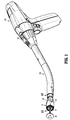
- FIGS. 1 and 2 illustrate a loading unit 10 and an adapter 100 in accordance with an embodiment of the present disclosure.
- the loading unit 10 is configured for selective connection to a powered hand held electromechanical instrument 200 via the adapter 100.
- the loading unit 10 can be configured for connection to a manually actuated handle assembly or stapling instrument such as described in U.S. Patent No. 8,789,737 ("the '737 Patent”), which is incorporated herein by reference.
- an elongated body portion of the stapling instrument may have a configuration similar to that of the adapter 100 as shown in FIG. 1 .
- the loading unit 10 is releasably coupled to a distal end portion 110 of the adapter 100 and includes a staple cartridge 12, a shell assembly 20, and an attachment member or locking band 40 for releasably securing the loading unit 10 to the adapter 100.
- the loading unit 10 may also include an anvil 90.
- the adapter 100 is configured to translate movement of a stapling instrument, e.g., an electromechanical instrument 200, to actuate the shell assembly 20, to effect approximation of the anvil 90 and the staple cartridge 12, and to suture and cut tissue (not shown).
- a proximal end 102 of the adapter 100 is attachable to the stapling instrument to actuate the staple cartridge 12. It is contemplated that the proximal end 102 of the adapter 100 may be attached to a manually actuated instrument such as described in the '737 Patent to actuate the staple cartridge 12.
- the distal end portion 110 of the adapter 100 or surgical instrument is tubular and defines a lug window 112 ( FIG. 4 ), hook windows 114, and a keyway 116.
- the lug window 112 extends through the distal end portion 110 and is spaced apart from a distal end 111 of the distal end portion 110 by a lift section 113.
- the hook windows 114 extend proximally from the distal end 111 of the distal end portion 110 in a direction parallel to a longitudinal axis of the distal end portion 110.
- the distal end portion 110 defines two hook windows 114 each positioned an equal distance from the lug window 112 in opposite directions from one another about the distal end portion 110.
- Each of the hook windows 114 may be offset approximately 90° about the distal end portion 110 away from the lug window 112 such that the hook windows 114 diametrically oppose one another.
- the keyway 116 is positioned between the hook windows 114 on a side of the distal end portion 110 opposing the lug window 112. As shown, the keyway 116 is adjacent one of the hook windows 114 and is spaced apart from the other one of the hook windows 114; however, it is contemplated that the keyway 116 may be equally spaced between the hook windows 114 such that the keyway 116 opposes the lug window 112.
- the keyway 116 extends proximally from the distal end 111 of the distal end portion 110 in a direction parallel to the longitudinal axis of the distal end portion 110.
- the adapter 100 includes a proximal stop 118 positioned about a proximal end of the distal end portion 110 of the adapter 100.
- the proximal stop 118 has a diameter greater than the distal end portion 110 and is positioned to abut a proximal end of the shell assembly 20 when the shell assembly 20 is positioned on the adapter 100.
- the shell assembly 20 has a proximal portion 22 that defines a central passage 21 for receiving the distal end portion 110 of the adapter 100 as detailed below.
- the proximal portion 22 includes an annular body 23 that defines an annular recess 24.
- the annular recess 24 extends about one half of the circumference of the annular body 23 and includes flats 26 at each end of the annular recess 24.
- the flats 26 are substantially parallel with one another and are positioned approximately 180° apart from one another on the annular body 23.
- the shell assembly 20 also includes a retaining or proximal ring 27 that has a constant diameter equal to or greater than a diameter of the annular body 23.
- the annular body 23 includes a key 36 and defines a lug opening 32, hook openings 34, and a tab receiver 38.
- the lug opening 32 passes through the annular body 23 and is positioned within the annular recess 24 approximately halfway between the flats 26.
- the hook openings 34 pass through the flats 26 of the annular body 23 transverse to a longitudinal axis of the shell assembly 20.
- Each flat 26 defines a detent groove or detent well 35 that is spaced apart from the hook opening 34 and positioned away from the annular recess 24.
- the tab receiver 38 is defined in the proximal portion 22 of the shell assembly 20 distal to and in communication with the annular recess 24.
- the tab receiver 38 is aligned with lug opening 32 and extends distally from the annular recess 24 in a direction parallel to a longitudinal axis of the shell assembly 20.
- the key 36 extends from an inner surface 23 of the annular body 23 between the hook openings 24.
- the proximal portion 22 may also define engagement recesses 28 ( FIG. 3 ) adjacent the flats 26 and positioned away from the annular recess 24.
- the locking band 40 includes a body 42 having ends 44, a lug 52, retention hooks 54, detents 55, and a tab 58.
- the body 42 is arced or semi-cylindrical in shape and is sized to be received within the annular recess 24 about the annular body 23 of the shell assembly 20.
- the lug 52 is positioned approximately halfway between the ends 44 and extends from an inner surface of the body 42.
- the lug 52 includes an angled proximal surface 53a and a vertical distal locking surface 53b such that the lug 52 is substantially wedge shaped.
- Each end 44 of the body 42 has a linear or flat inner surface 45 that is substantially parallel to the flat inner surface 45 of the opposing end 44.
- Each retention hook 54 is positioned adjacent an end 44 of the body 42 and extends inward from the flat inner surface 45.
- Each retention hook 54 includes a support member 142 and a hook member 144.
- the support member 142 extends orthogonally from the flat inner surface 45 towards the opposing flat inner surface 45.
- the hook member 144 extends substantially parallel to the flat inner surface 45 towards the lug 52.
- the hook member 144 includes a flat outer surface 146 that opposes the flat outer surface 146 of the hook member 144 of the other retention hook 54 and an angled inner surface 148 that opposes the flat inner surface 45 of the end 44.
- the hook member 144 is substantially wedge shaped with a leading end 149 of the hook member 144 having a smaller dimension than a trailing end 145 of the hook member 144.
- Each end 44 also includes a detent 55 protruding from the flat inner surface 45 and positioned adjacent the support member 142 of the retention hook 54 and away from the lug 52.
- the tab 58 extends distally from the body 42 in a direction parallel to a longitudinal axis of the shell assembly 20 when the body 42 is received within the annular recess 24.
- the tab 58 is axially aligned with the lug 52 and is sized to be received within the tab receiver 38 to index or align the locking band 40 with the shell assembly 20.
- the body 42 of the locking band 40 is receivable within the recess 24 of the annular body 23 of the shell assembly 20 to selectively secure the shell assembly 20 to the distal end portion 110 of the adapter 100 ( FIG. 1 ) as described in greater detail below.
- the tab 58 indexes or aligns the body 42 with the proximal portion 22 of the shell assembly 20 such that the lug 52 is aligned with the lug opening 32 and each retention hook 54 is aligned with a respective hook opening 34.
- the tab 58 provides visual indicia as to the proper alignment of the body 42 with the annular body 23.
- the retention hooks 54 are in a disengaged configuration within the hook openings 34.
- the trailing end 145 of the retention hooks 54 are adjacent to or in contact with a wall defining the respective hook opening 34 such that the support member 142 is adjacent or in contact with the wall defining the respective hook opening 34.
- the detents 55 are received in the detent wells 35 to prevent the respective end 44 of the body 42 from moving or sliding relative to the annular body 23.
- a respective end 44 of the body 42 may be engaged with a clinician's finger to slide the end 44 in the direction of the lug 52. This movement causes the body 42 of the locking band 40 to flex outwardly to lift a respective detent 55 from its detent well 35 and withdraw a respective retention hook 54 from its hook opening 34.
- the locking band 40 is aligned with the proximal portion 22 by placing the inner flats 45 on the flats 26 of the proximal portion 22.
- the inner flats 45 and the flats 26 of the annular body 23 are in contact with one another, alignment of the tab 58 and the tab recess 38 is visually verified to ensure the body 42 of the locking band 40 is in proper alignment with the annular body 23.
- pressure is applied to the body 42 such that the ends 44 of the body 42 slide over the flats 26 and the detents 55 engage the respective flats 26 to flex the body 42 outward.
- the retention hooks 54 engage the flats 26 to flex the ends 44 of the body 42 outward until the retention hooks 54 become aligned with the hook opening 34.
- the resiliency of the body 42 snaps or flexes the ends 44 inward such that the retention hooks 54 pass through the hook openings 34 and the detent 55 reengages the flat 26 past the hook opening 34. Additional pressure on the body 42 slides the detent 55 along the flat 26 until the detent 55 is received within the detent well 35 as shown in FIG. 6 .
- the detent 55 When the detent 55 is received within the detent well 35, the detent 55 may provide audible indicia, e.g., a "click,” to indicate to a clinician that the locking band 40 is secured to the annular body 23 of the shell assembly 20.
- audible indicia e.g., a "click”
- the locking band 40 is used to selectively secure the shell assembly 20 to the distal end portion 110 of the adapter 100 or surgical instrument as described in detail below.
- the longitudinal axis of the shell assembly 20 is aligned with the longitudinal axis of the distal end portion 110 of the adapter 100 with the locking band 40 coupled to the shell assembly 20.
- the shell assembly 20 is indexed or radially aligned with the distal end portion 110 of the adapter 100 such that the key 36 of the annular body 23 is aligned with the keyway 116 of the distal end portion 110.
- the lug window 112 of the distal end portion 110 is radially aligned with the lug opening 52 of the shell assembly 20 and the hook windows 114 of the distal end portion 110 are radially aligned with the hook openings 54 of the shell assembly 34.
- the annular body 23 of the shell assembly 20 is slid over the distal end portion 110.
- the key 36 is received within the keyway 116 of the distal end portion 110 to radially fix the shell assembly 20 with the distal end portion 110 of the adapter 100.
- the lift section 113 engages the lug 52 of the locking band 40 to transition the locking band 40 from the locked configuration to an unlocked configuration. Specifically, the lift section 113 engages the angled proximal surface 53a of the lug 52 to flex the body 42 outwardly to move the lug 52 outward until the lug 52 is positioned outside of the central passage 21 as shown in FIGS. 10 and 11 .
- the detents 55 of the locking band 40 remain disposed within the detent wells 35 of the annular body 23 with the lug 52 positioned outside of the central passage 21.
- the body 42 of the locking band 40 flexes outward between the ends 44 of the locking band 40 as the lug 52 moves from within the central passage 21.
- the retention hooks 54 may also engage walls defining the hook openings 34 to prevent the locking band 40 from decoupling or detaching from the annular body 23 of the shell assembly 20.
- the hook member 144 may capture the wall defining the hook opening 34 towards the lug 52 to secure the locking band 40 to the annular body 23 even if one or both of the detents 55 is released from within a respective detent well 35.
- the lift section 113 engages the lift section 113 to secure the distal end portion 110 of the adapter 100 within the proximal end 22 of the shell assembly 20 (i.e., the vertical surface 53b prevents the distal end portion 110 of the adapter 100 from withdrawing from the central passage 21 of the proximal end 22 of the shell assembly 20).
- the key 36 may abut an end of the keyway 116 to prevent the distal end portion 110 of the adapter 100 from over extending into the shell assembly 20.
- the retention hooks 54 may engage a proximal wall defining the hook windows 114 to prevent the distal end portion 110 from over extending into the shell assembly 20.
- the surgical instrument and shell assembly 20 may be used to perform a surgical procedure.
- the shell assembly 20 can be decoupled or detached from the surgical instrument as will be discussed in detail below.
- another shell assembly may be coupled to the surgical instrument to perform another stapling operation in the surgical procedure.
- the surgical instrument may be sterilized for use in another surgical procedure, or the surgical instrument may be discarded.
- the used shell assembly 20 may be sterilized for use in another surgical procedure or may be discarded.
- the locking band 40 is manipulated to decouple or release the shell assembly 20 from the distal end portion 110 of the adapter 100 such that the shell assembly 20 is removable from the distal end portion 110 of the adapter 100.
- the ends 44 of the locking band 40 are moved or slid towards the lug 52 to transition the locking band 40 to a released configuration as shown by arrow F in FIG. 14 .
- the flats 26 provide access to the ends 44 of the locking band 40 such that the ends 44 are engagable by fingers of a clinician.
- the detents 55 are moved out of the detent wells 35.
- the retention hooks 54 hook or engage a portion of the annular body 23 of the shell assembly 20 to prevent the locking band 40 from separating from the shell assembly 20.
- the hook members 144 of the retention hooks 54 engage a portion of the annular body 23 between the hook openings 34 and the lug opening 32.
- the leading ends 149 of the hook members 144 may engage a wall defining the hook window 114 of the distal end portion 110 and the annular body 23 may engage the support member 142 to prevent excessive movement of the end 44 of the locking band 40 towards the lug opening 32.
- the body 42 of the locking band 40 flexes to move the lug 52 outward such that the lug 52 is moved outside of the lug window 112 of the adapter 100 and may be moved outside of the lug opening 32 in the annular body 23.
- the locking band 40 may be manipulated to release the shell assembly 20 from the distal end portion 110 of the adapter 100 by engaging one end 44 of the locking band 40.
- a first end 44a of the locking band 40 is moved towards the lug 52, a first detent 55a adjacent the first end 44a is disengaged from a first detent well 35a and a second detent 55b adjacent a second end 44b remains engaged with a second detent well 35b.
- the body 42 of the locking band 40 flexes such that the lug 52 is moved outside of the lug window 112 of the adapter 100 such that the adapter 100 is separable from the shell assembly 20.
- a first retention hook 54a adjacent the first end 44a engages the annular body 23 and/or the distal end portion 110 to prevent excessive movement of the first end 44a towards the lug 52 in a manner similar to that detailed above.
- a second retention hook 54b adjacent the second end 44b and the second detent 55b engage features of the annular body 23 to resist or prevent movement of the second end 44b as the first end 44a is moved towards the lug 52.
- a support member 114b of the second retention hook 54b engages a wall defining the hook opening 34 in the annular body 23 and the second detent 55b engages the detent well 35b to resist or prevent movement of the second end 44b of the body 42 away from the lug 52.
Abstract
Description
- The present disclosure relates generally to surgical stapling instruments. More specifically, the present disclosure relates to circular stapling instruments having replaceable loading units.
- Surgical stapling instruments configured to join tissue portions during a surgical procedure are well known. These instruments include linear end effectors which are oriented parallel or transverse to a longitudinal axis of the instrument. These instruments also include circular end effectors. Typically, the linear stapling instruments include a disposable loading unit or a replaceable cartridge that allows the stapling instrument to be used multiple times. In contrast, conventional circular stapling instruments typically include a cartridge or shell assembly that is fixedly attached to the instrument such that the instrument must be disposed of after a single use.
- A need exists in the art for a simple, inexpensive instrument for releasably, but securely, fastening a cartridge or shell assembly to a circular stapling instrument to facilitate reuse of the stapling instrument.
- In an aspect of the present disclosure, a loading unit includes a shell assembly and a locking band. The shell assembly has a proximally extending annular body. The annular body defines two hook openings that oppose one another, a lug opening positioned between the hook openings, and a central passage for receiving a portion of a surgical instrument. The locking band has an arced body with two ends, a retention hook positioned adjacent each end of the body and extending from the inner surface of the body. Each of the retention hooks is disposed within a respective one of the hook opening to retain a respective one of the ends of the locking band to the annular body. The lug is disposable through the lug opening into the central passage to secure the loading unit to a surgical instrument.
- In aspects, each of the retention hooks has a disengaged configuration. When both of the retention hooks are in the disengaged configuration, the lug may extend through the lug opening into the central passage. Each end of the body may be moveable to move a respective one of the retention hooks towards an engaged configuration such that a portion of the retention hook engages the annular body between the respective hook opening and the lug window. Movement of the retention hooks towards the engaged position may cause the lug to be lifted outside of the central passage of the annular body to release a portion of the surgical instrument from the locking band.
- In some aspects, the lug opening is positioned halfway between the hook openings. The lug may be positioned halfway between the retention hooks. The annular body may define a recess between the hook openings. The recess may be configured to receive the body of the locking band. The locking band may include a tab that extends distally from the body. The shell assembly may define a tab receiver that is in communication with the recess. The tab receiver may be configured to receive the tab of the locking band to radially align the locking band to the shell assembly. The tab may be axially aligned with the lug.
- In certain aspects, the annular body includes flats adjacent each hook opening. The flats may define planes that are parallel to one another. Each end of the locking band may have a linear inner surface that slidably engages a respective one of the flats of the annular body. Each of the retention hooks may extend inward from a respective one of the liner inner surfaces. Each end of the locking band may also include a detent that extends inwardly from the respective linear inner surface that is positioned away from the retention hook and the lug. Each of the flats of the annular body may define a detent well. Each of the detent wells may be configured to receive a respective one of the detents. In a locked configuration of the locking band, each detent of the locking band may be received within a respective one of the detent wells and the lug may be positioned through the lug opening into the central passage. In an unlocked configuration of the locking band, each detent of the locking band may be received within a respective one of the detent walls and the lug may be positioned outside of the central passage. In a released configuration of the locking band, at least one of the detents may be disposed within a respective one of the hook openings and the lug may be positioned outside of the central passage.
- In another aspect of the present disclosure, a loading unit includes a shell assembly and a locking band. The shell assembly has a proximally extending annular body. The annular body defines two detent walls that are defined in an outer surface of the annular body spaced from one another, a lug opening extending through the annular body, and a central passage that receives a distal end portion of a surgical instrument. The locking band has an arced body with two ends. Each end of the arced body has a detent that extends from an inner surface of the body. The body includes an inwardly extending lug that is positioned between the ends. In a locked configuration of the body, each detent is received within a respective detent wall and the lug extends through the lug opening and into the central passage. In an unlocked configuration of the body, each detent is received within a respective detent well and the lug is positioned outside of the central passage. In a released configuration of the body, at least one detent is positioned about the annular body between a respective detent well and the lug opening and the lug is positioned outside of the central passage.
- In aspects, the annular body defines two flats that are parallel to one another on opposite sides of the annular body. A respective one of the detent wells may be defined in each of the flats. The shell assembly may define a hook opening between each of the detent walls and the lug opening. The locking band may include an inwardly extending retention hook that is positioned between each of the detents and the lug. The retention hooks may be configured to engage the annular body in the released configuration to secure a respective one of the ends of the locking band to the annular body. In the released configuration at least one of the detents is positioned in a respective one of the hook openings. The annular body may define two flats that are parallel to one another on opposite sides of the annular body. A respective one of the detent well and a respective one of the hook openings may be defined in each of the flats.
- In another aspect of the present disclosure, a surgical system includes a surgical instrument, a loading unit, and a locking band. The surgical instrument has a distal end portion that defines a lug opening. The loading unit includes a shell assembly that has a proximally extending annular body. The annular body defines two hook opening that oppose one another, a lug opening that is positioned between the hook openings, and a central passage that receives the distal end portion of the surgical instrument. The locking band has an arced body with two ends, a retention hook that is positioned adjacent each end of the body and extending from an inner surface of the body, and a lug that is positioned between the retention hoods and extending from the inner surface of the body. Each of the retention hooks is disposed within a respective one of the hook openings to retain a respective one of the ends of the locking band to the annular body. In a locked configuration of the body, the lug is disposed through the lug opening of the annular body and the lug window of the surgical instrument to secure the loading unit to the distal end portion of the surgical instrument.
- In aspects, the annular body includes a key that extends from an inner surface and is parallel to a longitudinal axis of the shell assembly. The distal end portion of the surgical instrument may define a keyway that is parallel to a longitudinal axis of the distal end portion. The keyway may slidably receive the key to rotatably align and fix the shell assembly to the distal end portion of the surgical instrument. The distal end portion may define hook windows that oppose one another. Each of the hook windows may receive one of the retention hooks of the locking band.
- In another aspect of the present disclosure, a method of providing a surgical instrument includes aligning a loading unit with a surgical instrument and sliding an annular body of the loading unit of a distal end portion of the surgical instrument. Aligning the loading unit with the surgical instrument includes aligning a longitudinal axis of the loading unit with a longitudinal axis of the distal end portion of the surgical instrument. When the loading unit and the surgical instrument are aligned, a lug opening defined through the annular body of a shell assembly of the loading unit is radially aligned with a lug windows defined through the distal end portion of the surgical instrument. When the annular body of the loading unit is slid over the distal end portion of the surgical instrument, the distal end portion engages a lug of a locking band that is disposed about the annular body to move the lug outwards as the loading unit slides over the distal end portion until the lug windows is aligned with the lug opening. Resilience of the body of the locking band snaps the lug through the lug window when the lug windows and the lug opening are longitudinally aligned to secure the loading unit to the distal end portion of the surgical instrument. The locking band has an arced body that includes a detent positioned adjacent each end. Each detent extends inward and is selectively received within a respective detent well defined in the annular body to fix the end of the body to the annular body as the annular body slides over the distal end portion of the surgical instrument.
- In aspects, the method may include releasing the loading unit from the distal end portion of the surgical instrument. Moving one of the ends of the body of the locking band towards the lug may slide the end relative to the annular body such that the detent disengages the respective detent well. The body may flex in response to moving the end of the body to move the lug out of the locking window so that distal end portion of the surgical instrument. When the lug out of the locking window of the distal end portion of the surgical instrument the method may include removing the loading unit from over the distal end portion of the surgical instrument.
- Further, to the extent consistent, any of the aspects described herein may be used in conjunction with any or all of the other aspects described herein.
- Various aspects of the present disclosure are described hereinbelow with reference to the drawings, which are incorporated in and constitute a part of this specification, wherein:
-
FIG. 1 is a perspective view of a surgical system in accordance with the present disclosure; -
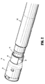
FIG. 2 is a perspective view of a distal end portion of the surgical system shown inFIG. 1 including a loading unit coupled to an adapter; -
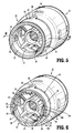
FIG. 3 is a perspective, exploded view from the proximal end of the loading unit and the distal end portion of the adapter ofFIG. 2 ; -
FIG. 4 is an exploded view of the loading unit and the distal end portion of the adapter ofFIG. 2 ; -
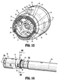
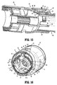
FIG. 5 is a perspective view from the proximal end of the loading unit ofFIG. 2 ; -
FIG. 6 is a cross-sectional view taken along the section line 6-6 ofFIG. 5 ; -
FIG. 7 is a side view of the loading unit ofFIG. 2 aligned with the distal end portion of the adapter ofFIG. 2 with a locking band of the loading unit in a locked configuration; -
FIG. 8 is a cross-sectional view taken along the section line 8-8 ofFIG. 7 ; -
FIG. 9 is a side view of the distal end portion of the adapter ofFIG. 7 partially received within the loading unit ofFIG. 7 with the locking band in an unlocked configuration; -
FIG. 10 is a cross-sectional view taken along the section line 10-10 ofFIG. 9 ; -
FIG. 11 is a cross-sectional view taken along the section line 11-11 ofFIG. 9 ; -
FIG. 12 is a cross-sectional view taken along the section line 12-12 ofFIG. 1 with the locking band in the locked configuration and the anvil removed; -
FIG. 13 is a cross-sectional view taken along the section line 13-13 ofFIG. 12 ; -
FIG. 14 is a side view of the distal end portion of the adapter and loading unit shown inFIG. 9 with the locking band of the loading unit in a released configuration; -
FIG. 15 is a cross-sectional view taken along the section line 15-15 ofFIG. 14 ; -
FIG. 16 is a cross-sectional view taken along the section line 16-16 ofFIG. 14 ; and -
FIG. 17 is a cross-sectional view of the distal end portion of the adapter and loading unit shown inFIG. 14 with the locking band of the loading unit in a released configuration. - Embodiments of the present disclosure are now described in detail with reference to the drawings in which like reference numerals designate identical or corresponding elements in each of the several views. As used herein, the term "clinician" refers to a doctor, a nurse, or any other care provider and may include support personnel. Throughout this description, the term "proximal" refers to the portion of the device or component thereof that is closest to the clinician and the term "distal" refers to the portion of the device or component thereof that is farthest from the clinician.
- This disclosure relates generally to a loading unit having a locking band that releasably secures the loading unit to the distal end portion of a surgical instrument or adapter for a surgical instrument. The locking band has a detent and a retention hook adjacent each end of the locking band that prevent the locking band from detaching from the loading unit when the loading unit is secured and released from the distal end portion of the surgical instrument.
-
FIGS. 1 and2 illustrate aloading unit 10 and anadapter 100 in accordance with an embodiment of the present disclosure. Theloading unit 10 is configured for selective connection to a powered hand heldelectromechanical instrument 200 via theadapter 100. Alternatively, theloading unit 10 can be configured for connection to a manually actuated handle assembly or stapling instrument such as described inU.S. Patent No. 8,789,737 ("the '737 Patent"), which is incorporated herein by reference. In such an embodiment, an elongated body portion of the stapling instrument may have a configuration similar to that of theadapter 100 as shown inFIG. 1 . In the illustrated embodiment, theloading unit 10 is releasably coupled to adistal end portion 110 of theadapter 100 and includes astaple cartridge 12, ashell assembly 20, and an attachment member or lockingband 40 for releasably securing theloading unit 10 to theadapter 100. Theloading unit 10 may also include ananvil 90. Theadapter 100 is configured to translate movement of a stapling instrument, e.g., anelectromechanical instrument 200, to actuate theshell assembly 20, to effect approximation of theanvil 90 and thestaple cartridge 12, and to suture and cut tissue (not shown). Aproximal end 102 of theadapter 100 is attachable to the stapling instrument to actuate thestaple cartridge 12. It is contemplated that theproximal end 102 of theadapter 100 may be attached to a manually actuated instrument such as described in the '737 Patent to actuate thestaple cartridge 12. - For a detailed description of the structure and function of an exemplary adapter and loading unit, please refer to commonly owned
U.S. Provisional Patent Application Serial No. 62/066,518, filed October 21, 2014 U.S. Patent Application Serial No. 13/484,975, filed on May 31, 2012 U.S. Patent Publication No. 2012/0253329 . Each of these applications is incorporated herein by reference in its entirety. - With reference to
FIGS. 3 and4 , thedistal end portion 110 of theadapter 100 or surgical instrument is tubular and defines a lug window 112 (FIG. 4 ),hook windows 114, and akeyway 116. Thelug window 112 extends through thedistal end portion 110 and is spaced apart from adistal end 111 of thedistal end portion 110 by alift section 113. Thehook windows 114 extend proximally from thedistal end 111 of thedistal end portion 110 in a direction parallel to a longitudinal axis of thedistal end portion 110. Thedistal end portion 110 defines twohook windows 114 each positioned an equal distance from thelug window 112 in opposite directions from one another about thedistal end portion 110. Each of thehook windows 114 may be offset approximately 90° about thedistal end portion 110 away from thelug window 112 such that thehook windows 114 diametrically oppose one another. Thekeyway 116 is positioned between thehook windows 114 on a side of thedistal end portion 110 opposing thelug window 112. As shown, thekeyway 116 is adjacent one of thehook windows 114 and is spaced apart from the other one of thehook windows 114; however, it is contemplated that thekeyway 116 may be equally spaced between thehook windows 114 such that thekeyway 116 opposes thelug window 112. Thekeyway 116 extends proximally from thedistal end 111 of thedistal end portion 110 in a direction parallel to the longitudinal axis of thedistal end portion 110. Theadapter 100 includes aproximal stop 118 positioned about a proximal end of thedistal end portion 110 of theadapter 100. Theproximal stop 118 has a diameter greater than thedistal end portion 110 and is positioned to abut a proximal end of theshell assembly 20 when theshell assembly 20 is positioned on theadapter 100. - The
shell assembly 20 has aproximal portion 22 that defines acentral passage 21 for receiving thedistal end portion 110 of theadapter 100 as detailed below. Theproximal portion 22 includes anannular body 23 that defines anannular recess 24. Theannular recess 24 extends about one half of the circumference of theannular body 23 and includesflats 26 at each end of theannular recess 24. Theflats 26 are substantially parallel with one another and are positioned approximately 180° apart from one another on theannular body 23. Theshell assembly 20 also includes a retaining orproximal ring 27 that has a constant diameter equal to or greater than a diameter of theannular body 23. - The
annular body 23 includes a key 36 and defines alug opening 32,hook openings 34, and atab receiver 38. The lug opening 32 passes through theannular body 23 and is positioned within theannular recess 24 approximately halfway between theflats 26. Thehook openings 34 pass through theflats 26 of theannular body 23 transverse to a longitudinal axis of theshell assembly 20. Each flat 26 defines a detent groove or detent well 35 that is spaced apart from thehook opening 34 and positioned away from theannular recess 24. Thetab receiver 38 is defined in theproximal portion 22 of theshell assembly 20 distal to and in communication with theannular recess 24. Thetab receiver 38 is aligned with lug opening 32 and extends distally from theannular recess 24 in a direction parallel to a longitudinal axis of theshell assembly 20. The key 36 extends from aninner surface 23 of theannular body 23 between thehook openings 24. Theproximal portion 22 may also define engagement recesses 28 (FIG. 3 ) adjacent theflats 26 and positioned away from theannular recess 24. - The locking
band 40 includes abody 42 having ends 44, alug 52, retention hooks 54,detents 55, and atab 58. Thebody 42 is arced or semi-cylindrical in shape and is sized to be received within theannular recess 24 about theannular body 23 of theshell assembly 20. Thelug 52 is positioned approximately halfway between theends 44 and extends from an inner surface of thebody 42. Thelug 52 includes an angledproximal surface 53a and a verticaldistal locking surface 53b such that thelug 52 is substantially wedge shaped. - Each
end 44 of thebody 42 has a linear or flatinner surface 45 that is substantially parallel to the flatinner surface 45 of the opposingend 44. Eachretention hook 54 is positioned adjacent anend 44 of thebody 42 and extends inward from the flatinner surface 45. Eachretention hook 54 includes asupport member 142 and ahook member 144. Thesupport member 142 extends orthogonally from the flatinner surface 45 towards the opposing flatinner surface 45. Thehook member 144 extends substantially parallel to the flatinner surface 45 towards thelug 52. Thehook member 144 includes a flatouter surface 146 that opposes the flatouter surface 146 of thehook member 144 of theother retention hook 54 and an angledinner surface 148 that opposes the flatinner surface 45 of theend 44. Thehook member 144 is substantially wedge shaped with aleading end 149 of thehook member 144 having a smaller dimension than a trailingend 145 of thehook member 144. Eachend 44 also includes adetent 55 protruding from the flatinner surface 45 and positioned adjacent thesupport member 142 of theretention hook 54 and away from thelug 52. Thetab 58 extends distally from thebody 42 in a direction parallel to a longitudinal axis of theshell assembly 20 when thebody 42 is received within theannular recess 24. Thetab 58 is axially aligned with thelug 52 and is sized to be received within thetab receiver 38 to index or align the lockingband 40 with theshell assembly 20. - With additional reference to
FIGS. 5 and 6 , thebody 42 of the lockingband 40 is receivable within therecess 24 of theannular body 23 of theshell assembly 20 to selectively secure theshell assembly 20 to thedistal end portion 110 of the adapter 100 (FIG. 1 ) as described in greater detail below. When thebody 42 of the lockingband 40 is received within therecess 24, thetab 58 indexes or aligns thebody 42 with theproximal portion 22 of theshell assembly 20 such that thelug 52 is aligned with thelug opening 32 and eachretention hook 54 is aligned with arespective hook opening 34. Thetab 58 provides visual indicia as to the proper alignment of thebody 42 with theannular body 23. When thelug 52 is received within thelug opening 32, the lockingband 40 is prevented from rotating relative to theshell assembly 20. - With continued reference to
FIGS. 5 and 6 , the retention hooks 54 are in a disengaged configuration within thehook openings 34. In the disengaged position, the trailingend 145 of the retention hooks 54 are adjacent to or in contact with a wall defining the respective hook opening 34 such that thesupport member 142 is adjacent or in contact with the wall defining therespective hook opening 34. In the disengaged position, thedetents 55 are received in thedetent wells 35 to prevent therespective end 44 of thebody 42 from moving or sliding relative to theannular body 23. In the disengaged configuration, arespective end 44 of thebody 42 may be engaged with a clinician's finger to slide theend 44 in the direction of thelug 52. This movement causes thebody 42 of the lockingband 40 to flex outwardly to lift arespective detent 55 from its detent well 35 and withdraw arespective retention hook 54 from itshook opening 34. - To selectively couple the locking
band 40 to theproximal portion 22 of theshell assembly 20 as shown inFIGS. 5 and 6 , the lockingband 40 is aligned with theproximal portion 22 by placing theinner flats 45 on theflats 26 of theproximal portion 22. When theinner flats 45 and theflats 26 of theannular body 23 are in contact with one another, alignment of thetab 58 and thetab recess 38 is visually verified to ensure thebody 42 of the lockingband 40 is in proper alignment with theannular body 23. When thebody 42 is properly aligned with theannular body 23, pressure is applied to thebody 42 such that the ends 44 of thebody 42 slide over theflats 26 and thedetents 55 engage therespective flats 26 to flex thebody 42 outward. As the ends 44 slide over theflats 26, the retention hooks 54 engage theflats 26 to flex theends 44 of thebody 42 outward until the retention hooks 54 become aligned with thehook opening 34. When the retention hooks 54 becomes aligned with thehook openings 34, the resiliency of thebody 42 snaps or flexes theends 44 inward such that the retention hooks 54 pass through thehook openings 34 and thedetent 55 reengages the flat 26 past thehook opening 34. Additional pressure on thebody 42 slides thedetent 55 along the flat 26 until thedetent 55 is received within the detent well 35 as shown inFIG. 6 . When thedetent 55 is received within the detent well 35, thedetent 55 may provide audible indicia, e.g., a "click," to indicate to a clinician that the lockingband 40 is secured to theannular body 23 of theshell assembly 20. When thedetents 55 are received in thedetent wells 35 and thelug 52 passes through thelug opening 32 and into thecentral passage 21, the lockingband 40 is in a locked configuration. - With reference to
FIGS. 7-13 , the lockingband 40 is used to selectively secure theshell assembly 20 to thedistal end portion 110 of theadapter 100 or surgical instrument as described in detail below. Initially referring toFIGS. 7 and 8 , to secure theshell assembly 20 to theadapter 100, the longitudinal axis of theshell assembly 20 is aligned with the longitudinal axis of thedistal end portion 110 of theadapter 100 with the lockingband 40 coupled to theshell assembly 20. Theshell assembly 20 is indexed or radially aligned with thedistal end portion 110 of theadapter 100 such that the key 36 of theannular body 23 is aligned with thekeyway 116 of thedistal end portion 110. When theshell assembly 20 is radially aligned with thedistal end portion 110 of theadapter 100, thelug window 112 of thedistal end portion 110 is radially aligned with the lug opening 52 of theshell assembly 20 and thehook windows 114 of thedistal end portion 110 are radially aligned with thehook openings 54 of theshell assembly 34. - Referring to
FIGS. 9-11 , when theshell assembly 20 and thedistal end portion 110 of theadapter 100 are longitudinally and radially aligned with one another, theannular body 23 of theshell assembly 20 is slid over thedistal end portion 110. Asdistal end portion 110 is received within thecentral passage 21 of theannular body 23, the key 36 is received within thekeyway 116 of thedistal end portion 110 to radially fix theshell assembly 20 with thedistal end portion 110 of theadapter 100. As theannular body 23 of theshell assembly 20 slides over thedistal end portion 110 of theadapter 100, thelift section 113, which is positioned between thedistal end 111 of thedistal end portion 110 and thelug window 112, engages thelug 52 of the lockingband 40 to transition the lockingband 40 from the locked configuration to an unlocked configuration. Specifically, thelift section 113 engages the angledproximal surface 53a of thelug 52 to flex thebody 42 outwardly to move thelug 52 outward until thelug 52 is positioned outside of thecentral passage 21 as shown inFIGS. 10 and11 . - With particular reference to
FIG. 11 , in the unlocked configuration, thedetents 55 of the lockingband 40 remain disposed within thedetent wells 35 of theannular body 23 with thelug 52 positioned outside of thecentral passage 21. As shown, thebody 42 of the lockingband 40 flexes outward between theends 44 of the lockingband 40 as thelug 52 moves from within thecentral passage 21. The retention hooks 54 may also engage walls defining thehook openings 34 to prevent thelocking band 40 from decoupling or detaching from theannular body 23 of theshell assembly 20. Specifically, thehook member 144 may capture the wall defining the hook opening 34 towards thelug 52 to secure thelocking band 40 to theannular body 23 even if one or both of thedetents 55 is released from within a respective detent well 35. - With reference to
FIGS. 12 and13 , additional insertion of thedistal end portion 110 of theadapter 100 into thecentral passage 21 of theannular body 23 slides thelift section 113 past thevertical surface 53b of thelug 52 such that thelug window 112 moves into alignment with thelug opening 32. When this occurs, resilience of thebody 42 of the lockingband 40 snaps or urges thelug 52 into thelug window 112 of thedistal end portion 110 of theadapter 100 such that the lockingband 40 returns to the locked configuration. When thelug 52 is positioned within thelug window 112, thevertical surface 53b of the lug 52 (FIG. 8 ) engages thelift section 113 to secure thedistal end portion 110 of theadapter 100 within theproximal end 22 of the shell assembly 20 (i.e., thevertical surface 53b prevents thedistal end portion 110 of theadapter 100 from withdrawing from thecentral passage 21 of theproximal end 22 of the shell assembly 20). The key 36 may abut an end of thekeyway 116 to prevent thedistal end portion 110 of theadapter 100 from over extending into theshell assembly 20. Additionally or alternatively, the retention hooks 54 may engage a proximal wall defining thehook windows 114 to prevent thedistal end portion 110 from over extending into theshell assembly 20. With particular reference toFIG. 13 , when thelug 52 is positioned within thelug window 112 to secure theshell assembly 20 to theadapter 100, thedetents 55 are received within thedetent wells 35 and the retention hooks 54 are positioned within thehook windows 114. - When the
shell assembly 20 is coupled to the surgical instrument, e.g., theadapter 100, the surgical instrument andshell assembly 20 may be used to perform a surgical procedure. After surgical procedure is completed, theshell assembly 20 can be decoupled or detached from the surgical instrument as will be discussed in detail below. With theshell assembly 20 decoupled from the surgical instrument, another shell assembly may be coupled to the surgical instrument to perform another stapling operation in the surgical procedure. Alternatively, the surgical instrument may be sterilized for use in another surgical procedure, or the surgical instrument may be discarded. In addition, the usedshell assembly 20 may be sterilized for use in another surgical procedure or may be discarded. - Referring to
FIGS. 14-17 , the lockingband 40 is manipulated to decouple or release theshell assembly 20 from thedistal end portion 110 of theadapter 100 such that theshell assembly 20 is removable from thedistal end portion 110 of theadapter 100. To release theshell assembly 20, the ends 44 of the lockingband 40 are moved or slid towards thelug 52 to transition the lockingband 40 to a released configuration as shown by arrow F inFIG. 14 . Theflats 26 provide access to theends 44 of the lockingband 40 such that the ends 44 are engagable by fingers of a clinician. As shown inFIG. 16 , when the ends 44 of the lockingband 40 are moved towards thelug 52, thedetents 55 are moved out of thedetent wells 35. As thedetents 55 are lifted from thedetent wells 35, the retention hooks 54 hook or engage a portion of theannular body 23 of theshell assembly 20 to prevent thelocking band 40 from separating from theshell assembly 20. Specifically, thehook members 144 of the retention hooks 54 engage a portion of theannular body 23 between thehook openings 34 and thelug opening 32. The leading ends 149 of thehook members 144 may engage a wall defining thehook window 114 of thedistal end portion 110 and theannular body 23 may engage thesupport member 142 to prevent excessive movement of theend 44 of the lockingband 40 towards thelug opening 32. As the ends 44 are moved towards thelug 52, thebody 42 of the lockingband 40 flexes to move thelug 52 outward such that thelug 52 is moved outside of thelug window 112 of theadapter 100 and may be moved outside of the lug opening 32 in theannular body 23. - With reference to
FIG. 17 , the lockingband 40 may be manipulated to release theshell assembly 20 from thedistal end portion 110 of theadapter 100 by engaging oneend 44 of the lockingband 40. As shown inFIG. 17 , when afirst end 44a of the lockingband 40 is moved towards thelug 52, afirst detent 55a adjacent thefirst end 44a is disengaged from afirst detent well 35a and a second detent 55b adjacent asecond end 44b remains engaged with asecond detent well 35b. As this occurs, thebody 42 of the lockingband 40 flexes such that thelug 52 is moved outside of thelug window 112 of theadapter 100 such that theadapter 100 is separable from theshell assembly 20. Afirst retention hook 54a adjacent thefirst end 44a engages theannular body 23 and/or thedistal end portion 110 to prevent excessive movement of thefirst end 44a towards thelug 52 in a manner similar to that detailed above. Asecond retention hook 54b adjacent thesecond end 44b and the second detent 55b engage features of theannular body 23 to resist or prevent movement of thesecond end 44b as thefirst end 44a is moved towards thelug 52. Specifically, asupport member 114b of thesecond retention hook 54b engages a wall defining the hook opening 34 in theannular body 23 and the second detent 55b engages thedetent well 35b to resist or prevent movement of thesecond end 44b of thebody 42 away from thelug 52. - While several embodiments of the disclosure have been shown in the drawings, it is not intended that the disclosure be limited thereto, as it is intended that the disclosure be as broad in scope as the art will allow and that the specification be read likewise. Any combination of the above embodiments is also envisioned and is within the scope of the appended claims. The present disclosure is not limited to circular stapling loading units, but has application to loading units for linear stapling or other types of instruments, such as electrocautery or ultrasonic instruments. Therefore, the above description should not be construed as limiting, but merely as exemplifications of particular embodiments. Those skilled in the art will envision other modifications within the scope of the claims appended hereto.
- The invention may be described by reference to the following numbered paragraphs:-
- 1. A loading unit comprising:
- a shell assembly having a proximally extending annular body, the annular body defining two hook openings that oppose one another, a lug opening positioned between the hook openings, and a central passage for receiving a portion of a surgical instrument; and
- a locking band having an arced body with two ends, a retention hook positioned adjacent each end of the body and extending from an inner surface of the body, and a lug positioned between the retention hooks and extending from the inner surface of the body, each retention hook disposed within a respective one of the hook openings to retain a respective one of the ends of the locking band to the annular body, the lug disposable through the lug opening into the central passage to secure the loading unit to the surgical instrument.
- 2. The loading unit according to paragraph 1, wherein each of the retention hooks has a disengaged configuration, and wherein when both of the retention hooks are in the disengaged configuration the lug extends through the lug opening into the central passage.
- 3. The loading unit according to
paragraph 2, wherein each end of the body is moveable to move a respective one of the retention hooks towards an engaged configuration such that a portion of the retention hook engages the annular body between the respective hook opening and the lug window, and wherein movement of the retention hooks towards the engaged position causes the lug to be lifted outside of the central passage of the annular body to release the portion of the surgical instrument from the locking band. - 4. The loading unit according to paragraph 1, wherein the annular body defines a recess between the hook openings, the recess being configured to receive the body of the locking band.
- 5. The loading unit according to paragraph 4, wherein the locking band includes a tab extending distally from the body, and wherein the shell assembly defines a tab receiver in communication with the recess, the tab receiver configured to receive the tab of the locking band to radially align the locking band to the shell assembly.
- 6. The loading unit according to
paragraph 5, wherein the tab is axially aligned with the lug. - 7. The loading unit according to paragraph 1, wherein the annular body includes flats adjacent each hook opening, the flats defining planes that are parallel to one another.
- 8. The loading unit according to paragraph 7, wherein each end of the locking band has a linear inner surface that slidably engages a respective one of the flats of the annular body, each retention hook extending inward from a respective one of the linear inner surfaces.
- 9. The loading unit according to paragraph 8, wherein each end of the locking band includes a detent extending inwardly from the respective linear inner surface positioned away from the retention hook and the lug, and wherein each of the flats of the annular body defines a detent well configured to receive a respective one of the detents.
- 10. The loading unit according to paragraph 9, wherein in a locked configuration of the locking band, each detent of the locking band is received within a respective one of the detent wells and the lug is positioned through the lug opening into the central passage, and wherein in an unlocked configuration of the locking band each detent of the locking band is received within a respective one of the detent wells and the lug is positioned outside of the central passage.
- 11. The loading unit according to
paragraph 10, wherein in a released configuration of the locking band at least one of the detents is disposed within a respective one of the hook openings and the lug is positioned outside of the central passage. - 12. A loading unit comprising:
- a shell assembly having a proximally extending annular body, the annular body defining two detent wells defined in an outer surface of the annular body spaced from one another, a lug opening extending through the annular body, and a central passage for receiving a distal end portion of a surgical instrument; and
- a locking band having an arced body with two ends, each end having a detent extending from an inner surface of the body, the body including an inwardly extending lug positioned between the ends, the locking band having a locked configuration in which each detent is received within a respective detent well and the lug extends through the lug opening and into the central passage, an unlocked configuration in which each detent is received within a respective detent well and the lug is positioned outside of the central passage, and a released configuration in which at least one detent is positioned about the annular body between a respective detent well and the lug opening and the lug is positioned outside of the central passage.
- 13. The loading unit according to
paragraph 12, wherein the annular body defines two flats that are parallel to one another on opposite sides of the annular body, a respective one of the detent wells being defined in each of the flats. - 14. The loading unit according to
paragraph 12, wherein the shell assembly defines hook opening between each of the detent wells and the lug openings. - 15. The loading unit according to paragraph 14, wherein the locking band includes an inwardly extending retention hook positioned between each of the detents and the lug, the retention hooks being configured to engage the annular body in the released configuration to secure a respective one of the ends of the locking band to the annular body.
- 16. The loading unit according to paragraph 14, wherein in the released configuration the at least one detent is positioned in a respective one of the hook openings.
- 17. The loading unit according to
paragraph 16, wherein the annular body defines two flats that are parallel to one another on opposite sides of the annular body, a respective one of the detent wells and a respective one of the hook openings defined in each of the flats. - 18. A surgical system comprising:
- a surgical instrument having a distal end portion, the distal end portion defining a lug window;
- a loading unit including a shell assembly having a proximally extending annular body, the annular body defining two hook openings that oppose one another, a lug opening positioned between the hook openings, and a central passage that receives the distal end portion of the surgical instrument; and
- a locking band having an arced body with two ends, a retention hook positioned adjacent each end of the body and extending from an inner surface of the body, and a lug positioned between the retention hooks and extending from the inner surface of the body, each retention hook disposed within a respective one of the hook openings to retain a respective one of the ends of the locking band to the annular body, in a locked configuration of the body the lug is disposed through the lug opening of the annular body and the lug window of the surgical instrument to secure the loading unit to the distal end portion of the surgical instrument.
- 19. The surgical system according to
paragraph 18, wherein the annular body includes a key extending from an inner surface and parallel to a longitudinal axis of the shell assembly, and wherein the distal end portion of the surgical instrument defines a keyway that is parallel to a longitudinal axis of the distal end portion, the keyway slidably receiving the key to rotatably align and fix the shell assembly to the distal end portion of the surgical instrument. - 20. The surgical system according to
paragraph 18, wherein the distal end portion defines hook windows that oppose one another, each of the hook windows receiving one of the retention hooks of the locking band.
Claims (15)
- A loading unit comprising:a shell assembly having a proximally extending annular body, the annular body defining two hook openings that oppose one another, a lug opening positioned between the hook openings, and a central passage for receiving a portion of a surgical instrument; anda locking band having an arced body with two ends, a retention hook positioned adjacent each end of the body and extending from an inner surface of the body, and a lug positioned between the retention hooks and extending from the inner surface of the body, each retention hook disposed within a respective one of the hook openings to retain a respective one of the ends of the locking band to the annular body, the lug disposable through the lug opening into the central passage to secure the loading unit to the surgical instrument.
- The loading unit according to claim 1, wherein each of the retention hooks has a disengaged configuration, and wherein when both of the retention hooks are in the disengaged configuration the lug extends through the lug opening into the central passage; preferably wherein each end of the body is moveable to move a respective one of the retention hooks towards an engaged configuration such that a portion of the retention hook engages the annular body between the respective hook opening and the lug window, and wherein movement of the retention hooks towards the engaged position causes the lug to be lifted outside of the central passage of the annular body to release the portion of the surgical instrument from the locking band.
- The loading unit according to claim 1 or claim 2, wherein the annular body defines a recess between the hook openings, the recess being configured to receive the body of the locking band.
- The loading unit according to claim 3, wherein the locking band includes a tab extending distally from the body, and wherein the shell assembly defines a tab receiver in communication with the recess, the tab receiver configured to receive the tab of the locking band to radially align the locking band to the shell assembly; preferably wherein the tab is axially aligned with the lug.
- The loading unit according to any preceding claim, wherein the annular body includes flats adjacent each hook opening, the flats defining planes that are parallel to one another.
- The loading unit according to claim 5, wherein each end of the locking band has a linear inner surface that slidably engages a respective one of the flats of the annular body, each retention hook extending inward from a respective one of the linear inner surfaces; preferably wherein each end of the locking band includes a detent extending inwardly from the respective linear inner surface positioned away from the retention hook and the lug, and wherein each of the flats of the annular body defines a detent well configured to receive a respective one of the detents.
- The loading unit according to claim 6, wherein in a locked configuration of the locking band, each detent of the locking band is received within a respective one of the detent wells and the lug is positioned through the lug opening into the central passage, and wherein in an unlocked configuration of the locking band each detent of the locking band is received within a respective one of the detent wells and the lug is positioned outside of the central passage; preferably wherein in a released configuration of the locking band at least one of the detents is disposed within a respective one of the hook openings and the lug is positioned outside of the central passage.
- A loading unit comprising:a shell assembly having a proximally extending annular body, the annular body defining two detent wells defined in an outer surface of the annular body spaced from one another, a lug opening extending through the annular body, and a central passage for receiving a distal end portion of a surgical instrument; anda locking band having an arced body with two ends, each end having a detent extending from an inner surface of the body, the body including an inwardly extending lug positioned between the ends, the locking band having a locked configuration in which each detent is received within a respective detent well and the lug extends through the lug opening and into the central passage, an unlocked configuration in which each detent is received within a respective detent well and the lug is positioned outside of the central passage, and a released configuration in which at least one detent is positioned about the annular body between a respective detent well and the lug opening and the lug is positioned outside of the central passage.
- The loading unit according to claim 8, wherein the annular body defines two flats that are parallel to one another on opposite sides of the annular body, a respective one of the detent wells being defined in each of the flats; preferably wherein the shell assembly defines hook opening between each of the detent wells and the lug openings.
- The loading unit according to claim 9, wherein the locking band includes an inwardly extending retention hook positioned between each of the detents and the lug, the retention hooks being configured to engage the annular body in the released configuration to secure a respective one of the ends of the locking band to the annular body.
- The loading unit according to claim 9 or claim 10, wherein in the released configuration the at least one detent is positioned in a respective one of the hook openings.
- The loading unit according to claim 11, wherein the annular body defines two flats that are parallel to one another on opposite sides of the annular body, a respective one of the detent wells and a respective one of the hook openings defined in each of the flats.
- A surgical system comprising:a surgical instrument having a distal end portion, the distal end portion defining a lug window;a loading unit including a shell assembly having a proximally extending annular body, the annular body defining two hook openings that oppose one another, a lug opening positioned between the hook openings, and a central passage that receives the distal end portion of the surgical instrument; anda locking band having an arced body with two ends, a retention hook positioned adjacent each end of the body and extending from an inner surface of the body, and a lug positioned between the retention hooks and extending from the inner surface of the body, each retention hook disposed within a respective one of the hook openings to retain a respective one of the ends of the locking band to the annular body, in a locked configuration of the body the lug is disposed through the lug opening of the annular body and the lug window of the surgical instrument to secure the loading unit to the distal end portion of the surgical instrument.
- The surgical system according to claim 13, wherein the annular body includes a key extending from an inner surface and parallel to a longitudinal axis of the shell assembly, and wherein the distal end portion of the surgical instrument defines a keyway that is parallel to a longitudinal axis of the distal end portion, the keyway slidably receiving the key to rotatably align and fix the shell assembly to the distal end portion of the surgical instrument.
- The surgical system according to claim 13 or claim 14, wherein the distal end portion defines hook windows that oppose one another, each of the hook windows receiving one of the retention hooks of the locking band.
Applications Claiming Priority (1)
| Application Number | Priority Date | Filing Date | Title |
|---|---|---|---|
| US14/805,547 US10117655B2 (en) | 2015-07-22 | 2015-07-22 | Loading unit locking band for surgical stapling instrument |
Publications (3)
| Publication Number | Publication Date |
|---|---|
| EP3141195A2 true EP3141195A2 (en) | 2017-03-15 |
| EP3141195A3 EP3141195A3 (en) | 2017-05-17 |
| EP3141195B1 EP3141195B1 (en) | 2020-04-01 |
Family
ID=56497655
Family Applications (1)
| Application Number | Title | Priority Date | Filing Date |
|---|---|---|---|
| EP16180339.0A Active EP3141195B1 (en) | 2015-07-22 | 2016-07-20 | Loading unit locking band for surgical stapling instrument |
Country Status (7)
| Country | Link |
|---|---|
| US (2) | US10117655B2 (en) |
| EP (1) | EP3141195B1 (en) |
| JP (1) | JP6758975B2 (en) |
| CN (1) | CN106361395B (en) |
| AU (2) | AU2016204201B2 (en) |
| CA (1) | CA2934146A1 (en) |
| ES (1) | ES2794402T3 (en) |
Families Citing this family (26)
| Publication number | Priority date | Publication date | Assignee | Title |
|---|---|---|---|---|
| US9730694B2 (en) * | 2014-07-01 | 2017-08-15 | Covidien Lp | Loading unit including shipping assembly |
| US10039549B2 (en) * | 2015-01-07 | 2018-08-07 | Covidien Lp | Loading unit retention clip for surgical stapling instrument |
| US10881408B2 (en) * | 2015-04-22 | 2021-01-05 | Covidien Lp | Interlock assembly for replaceable loading units |
| US10117655B2 (en) | 2015-07-22 | 2018-11-06 | Covidien Lp | Loading unit locking band for surgical stapling instrument |
| US10194912B2 (en) * | 2015-07-28 | 2019-02-05 | Ethicon Llc | Surgical staple cartridge with outer edge compression features |
| US9980730B2 (en) * | 2015-09-21 | 2018-05-29 | Covidien Lp | Loading unit locking collar with rotational actuated release |
| EP3498682B1 (en) | 2017-12-12 | 2022-03-30 | Shin-Etsu Chemical Co., Ltd. | Preparation of sinterable garnet-structure complex oxide powder and manufacturing of transparent ceramics |
| CA3139541A1 (en) | 2019-05-31 | 2020-12-03 | Covidien Lp | Circular stapling device |
| US11622767B2 (en) | 2020-02-19 | 2023-04-11 | Covidien Lp | Sealed trocar assembly for stapling device |
| US11779343B2 (en) | 2020-02-26 | 2023-10-10 | Covidien Lp | Staple reload assembly with releasable knife |
| US11653925B2 (en) | 2020-05-21 | 2023-05-23 | Covidien Lp | Tissue relaxation monitoring for optimized tissue stapling |
| US11547405B2 (en) | 2020-05-22 | 2023-01-10 | Covidien Lp | Surgical stapling device |
| US11553921B2 (en) | 2020-07-15 | 2023-01-17 | Covidien Lp | Surgical stapling device with flexible shaft |
| US11627966B2 (en) | 2020-08-26 | 2023-04-18 | Covidien Lp | Surgical stapling device |
| US11801054B2 (en) | 2020-09-22 | 2023-10-31 | Covidien Lp | Surgical stapler with oval tool assembly |
| US11712509B2 (en) | 2020-10-02 | 2023-08-01 | Covidien Lp | Seal assembly for circular stapling instrument |
| US11627967B2 (en) | 2020-11-23 | 2023-04-18 | Covidien Lp | Trans-anastomotic insertion device |
| US11877750B2 (en) | 2021-01-21 | 2024-01-23 | Covidien Lp | Surgical stapler with powered and manual functions |
| US11786241B2 (en) | 2021-02-16 | 2023-10-17 | Covidien Lp | Surgical stapling device including a hydraulic staple formation mechanism |
| US11553920B2 (en) | 2021-05-03 | 2023-01-17 | Covidien Lp | Trocar retainer assembly for surgical stapler |
| US11490894B1 (en) | 2021-05-12 | 2022-11-08 | Covidien Lp | Surgical device with grease filter |
| US11642131B2 (en) | 2021-05-17 | 2023-05-09 | Covidien Lp | Devices and methods for shortening a rectal stump during a lower anterior resection procedure |
| US11612400B2 (en) | 2021-05-24 | 2023-03-28 | Covidien Lp | Trocar assembly with bearing assembly for load sharing |
| US11737759B2 (en) | 2021-08-05 | 2023-08-29 | Covidien Lp | Surgical stapling device accommodating prolapsed tissue |
| US11883028B2 (en) | 2021-09-08 | 2024-01-30 | Covidien Lp | Systems and methods for post-operative anastomotic leak detection |
| US11717299B2 (en) | 2021-10-12 | 2023-08-08 | Covidien Lp | Surgical stapling device with probiotics |
Citations (2)
| Publication number | Priority date | Publication date | Assignee | Title |
|---|---|---|---|---|
| US20120253329A1 (en) | 2007-09-21 | 2012-10-04 | Michael Zemlok | Hand held surgical handle assembly, surgical adapters for use between surgical handle assembly and surgical end effectors, and methods of use |
| US8789737B2 (en) | 2011-04-27 | 2014-07-29 | Covidien Lp | Circular stapler and staple line reinforcement material |
Family Cites Families (435)
| Publication number | Priority date | Publication date | Assignee | Title |
|---|---|---|---|---|
| CA908529A (en) | 1972-08-29 | V. Astafiev Georgy | Surgical instrument for suturing hollow organs in infants | |
| US2110397A (en) * | 1937-01-29 | 1938-03-08 | Kangas Francis | Drill |
| US2304038A (en) * | 1940-05-28 | 1942-12-01 | Ingersoll Rand Co | Locking device |
| DE1057729B (en) | 1954-03-29 | 1959-05-21 | Lameris Instr N V | Surgical device for connecting two parts of the intestine |
| GB787043A (en) | 1954-09-15 | 1957-11-27 | Sylvania Electric Prod | Method for production of silicon |
| CA736256A (en) | 1962-08-27 | 1966-06-14 | S. Kasoolin Viacheslav | Instrument for suturing esophagus to intestine or stomach |
| US3245703A (en) * | 1963-10-28 | 1966-04-12 | Robert S Manly | Quick detachable pipe coupling |
| FR1461464A (en) | 1965-08-20 | 1966-02-25 | Niiex Khirurgicheskoi Apparatu | Surgical device for suturing organs |
| CH470170A (en) | 1968-02-02 | 1969-03-31 | Vnii Khirurgicheskoi Apparatur | Device for applying round anastomoses |
| US3656494A (en) * | 1970-05-11 | 1972-04-18 | Coleman Co | Adjustable tent pole |
| US3638652A (en) | 1970-06-01 | 1972-02-01 | James L Kelley | Surgical instrument for intraluminal anastomosis |
| FR2144022A5 (en) * | 1971-06-29 | 1973-02-09 | Schlumberger Inst System | |
| US3753582A (en) * | 1971-11-09 | 1973-08-21 | Anarak Inc | Coupling unit |
| US3771526A (en) | 1972-02-07 | 1973-11-13 | P Rudie | Anastomosis clamp |
| SE7317355L (en) | 1973-09-18 | 1975-03-19 | Bahmuller Wilhelm | |
| US3980805A (en) * | 1975-03-31 | 1976-09-14 | Bell Telephone Laboratories, Incorporated | Quick release sleeve fastener |
| NL164368C (en) * | 1977-04-12 | 1980-12-15 | Bijstede Bv Ind & Handel | LOCKING DEVICE FOR LOCKING TWO MATCHING CYLINDRICAL PARTS COMPATIBLE. |
| US4573468A (en) | 1977-05-26 | 1986-03-04 | United States Surgical Corporation | Hollow body organ stapling instrument and disposable cartridge employing relief vents |
| US4603693A (en) | 1977-05-26 | 1986-08-05 | United States Surgical Corporation | Instrument for circular surgical stapling of hollow body organs and disposable cartridge therefor |
| US4304236A (en) | 1977-05-26 | 1981-12-08 | United States Surgical Corporation | Stapling instrument having an anvil-carrying part of particular geometric shape |
| NL7711347A (en) | 1977-10-17 | 1979-04-19 | Carl Robert Erik Daantje | Stapling instrument for joining intestine ends - has head coupling rod in two parts screwing together with hand grip |
| US4207898A (en) | 1978-03-27 | 1980-06-17 | Senco Products, Inc. | Intralumenal anastomosis surgical stapling instrument |
| US4198982A (en) | 1978-03-31 | 1980-04-22 | Memorial Hospital For Cancer And Allied Diseases | Surgical stapling instrument and method |
| DE2947107A1 (en) | 1978-12-07 | 1980-06-26 | United States Surgical Corp | ACCURATELY ALIGNED CARTRIDGE AND INSTRUMENT FOR CLAMPING ANASTOMOSES |
| DE2855682A1 (en) * | 1978-12-22 | 1980-07-03 | Siemens Ag | DEVICE FOR DETACHABLY CONNECTING TWO AXIAL TOGETHER WITH DENTAL DENTAL HANDPIECE OR THE LIKE. -SHARE |
| SU1088712A1 (en) | 1979-11-14 | 1984-04-30 | Всесоюзный научно-исследовательский и испытательный институт медицинской техники | Apparatus for circular suture of blood vessels |
| AU534210B2 (en) | 1980-02-05 | 1984-01-12 | United States Surgical Corporation | Surgical staples |
| US4319576A (en) | 1980-02-26 | 1982-03-16 | Senco Products, Inc. | Intralumenal anastomosis surgical stapling instrument |
| US4289133A (en) | 1980-02-28 | 1981-09-15 | Senco Products, Inc. | Cut-through backup washer for the scalpel of an intraluminal surgical stapling instrument |
| US4606343A (en) | 1980-08-18 | 1986-08-19 | United States Surgical Corporation | Self-powered surgical fastening instrument |
| US4351466A (en) | 1980-10-16 | 1982-09-28 | United States Surgical Corporation | Disposable instrument for surgical fastening |
| US4379457A (en) | 1981-02-17 | 1983-04-12 | United States Surgical Corporation | Indicator for surgical stapler |
| US4476863A (en) | 1981-03-09 | 1984-10-16 | Kanshin Nikolai N | Surgical instrument for establishing circular coloanastomoses |
| US4632290A (en) | 1981-08-17 | 1986-12-30 | United States Surgical Corporation | Surgical stapler apparatus |
| US4576167A (en) | 1981-09-03 | 1986-03-18 | United States Surgical Corporation | Surgical stapler apparatus with curved shaft |
| SU1114405A1 (en) | 1982-02-23 | 1984-09-23 | Всесоюзный научно-исследовательский и испытательный институт медицинской техники | Surgical suturing apparatus for placing compression anastomoses on the organs of digestive tract |
| US4473077A (en) | 1982-05-28 | 1984-09-25 | United States Surgical Corporation | Surgical stapler apparatus with flexible shaft |
| US4485817A (en) | 1982-05-28 | 1984-12-04 | United States Surgical Corporation | Surgical stapler apparatus with flexible shaft |
| US4488523A (en) | 1982-09-24 | 1984-12-18 | United States Surgical Corporation | Flexible, hydraulically actuated device for applying surgical fasteners |
| DE3301713A1 (en) | 1983-01-20 | 1984-07-26 | Horst Dr. 3004 Isernhagen Ziegler | Surgical clip suture apparatus for producing circular joins |
| US4592354A (en) | 1983-10-11 | 1986-06-03 | Senmed, Inc. | Tissue retention spool for intraluminal anastomotic surgical stapling instrument and methods |
| US4505414A (en) | 1983-10-12 | 1985-03-19 | Filipi Charles J | Expandable anvil surgical stapler |
| US4550870A (en) | 1983-10-13 | 1985-11-05 | Alchemia Ltd. Partnership | Stapling device |
| IT1173284B (en) | 1984-02-16 | 1987-06-18 | Riccardo Rosati | CIRCULAR MECHANICAL STAPLING MACHINE |
| US4667673A (en) | 1984-03-12 | 1987-05-26 | American Cyanamid Company | Anastomotic device applicator and method |
| US4671445A (en) | 1984-08-09 | 1987-06-09 | Baxter Travenol Laboratories, Inc. | Flexible surgical stapler assembly |
| US4754909A (en) | 1984-08-09 | 1988-07-05 | Barker John M | Flexible stapler |
| US4627761A (en) * | 1984-09-28 | 1986-12-09 | Snap-On Tools Corporation | Retainer |
| US4647241A (en) * | 1984-12-07 | 1987-03-03 | Weber William J | Modular assembly and retainer therefor |
| US4703887A (en) | 1985-01-28 | 1987-11-03 | Ethicon, Inc. | Collapsible purse string aid for use with intraluminal stapling device |
| AU582625B2 (en) | 1985-01-28 | 1989-04-06 | Ethicon Inc. | Tissue gripper for use with intraluminal stapling device |
| US4665917A (en) | 1985-01-28 | 1987-05-19 | Ethicon, Inc. | Tissue gripper for use with intraluminal stapling device |
| JPS635697Y2 (en) | 1985-04-04 | 1988-02-17 | ||
| JPS62140776A (en) | 1985-12-16 | 1987-06-24 | 海老原 代師行 | Stapler |
| US4903697A (en) | 1986-03-27 | 1990-02-27 | Semion Resnick | Cartridge assembly for a surgical stapling instrument |
| US4700703A (en) | 1986-03-27 | 1987-10-20 | Semion Resnick | Cartridge assembly for a surgical stapling instrument |
| WO1987006448A1 (en) | 1986-04-21 | 1987-11-05 | Finanzaktiengesellschaft Globe Control | Anastomosis process and device |
| US4752024A (en) | 1986-10-17 | 1988-06-21 | Green David T | Surgical fastener and surgical stapling apparatus |
| US4917114A (en) | 1986-10-17 | 1990-04-17 | United States Surgical Corporation | Surgical fastener and surgical stapling apparatus |
| US4776506A (en) | 1986-11-13 | 1988-10-11 | United States Surgical Corporation | Surgical stapler apparatus |
| US4873977A (en) | 1987-02-11 | 1989-10-17 | Odis L. Avant | Stapling method and apparatus for vesicle-urethral re-anastomosis following retropubic prostatectomy and other tubular anastomosis |
| US5119983A (en) | 1987-05-26 | 1992-06-09 | United States Surgical Corporation | Surgical stapler apparatus |
| US5285944A (en) | 1987-05-26 | 1994-02-15 | United States Surgical Corporation | Surgical stapler apparatus |
| US5158222A (en) | 1987-05-26 | 1992-10-27 | United States Surgical Corp. | Surgical stapler apparatus |
| SU1616624A1 (en) | 1987-07-14 | 1990-12-30 | Предприятие П/Я А-3697 | Surgical suturing apparatus |
| US4802700B1 (en) * | 1987-11-09 | 1996-10-01 | Transguard Ind Inc | Locking seal |
| SU1509052A1 (en) | 1988-01-18 | 1989-09-23 | С. А. Попов | Surgical suturing apparatus |
| US4907591A (en) | 1988-03-29 | 1990-03-13 | Pfizer Hospital Products Group, Inc. | Surgical instrument for establishing compression anastomosis |
| US5193731A (en) | 1988-07-01 | 1993-03-16 | United States Surgical Corporation | Anastomosis surgical stapling instrument |
| US5005749A (en) | 1988-07-01 | 1991-04-09 | United States Surgical Corp. | Anastomosis surgical stapling instrument |
| ES2011110A6 (en) | 1988-09-02 | 1989-12-16 | Lopez Hervas Pedro | Hydraulic device with flexible body for surgical anastomosts |
| US4869534A (en) * | 1988-09-26 | 1989-09-26 | Huron Products Corporation | Swivelable quick connector |
| WO1990006085A1 (en) | 1988-11-29 | 1990-06-14 | Gingold Bruce S | Surgical stapling apparatus |
| US5197648A (en) | 1988-11-29 | 1993-03-30 | Gingold Bruce S | Surgical stapling apparatus |
| US4893662A (en) | 1988-12-06 | 1990-01-16 | Vito Gervasi | Cutting tool |
| CH677728A5 (en) | 1989-10-17 | 1991-06-28 | Bieffe Medital Sa | |
| US5403333A (en) | 1990-08-28 | 1995-04-04 | Robert L. Kaster | Side-to-end vascular anastomotic staple apparatus |
| US5047039A (en) | 1990-09-14 | 1991-09-10 | Odis Lynn Avant | Method and apparatus for effecting dorsal vein ligation and tubular anastomosis and laparoscopic prostatectomy |
| US5253793A (en) | 1990-09-17 | 1993-10-19 | United States Surgical Corporation | Apparatus for applying two-part surgical fasteners |
| US5104025A (en) | 1990-09-28 | 1992-04-14 | Ethicon, Inc. | Intraluminal anastomotic surgical stapler with detached anvil |
| US5042707A (en) | 1990-10-16 | 1991-08-27 | Taheri Syde A | Intravascular stapler, and method of operating same |
| CA2055943C (en) | 1990-12-06 | 2003-09-23 | Daniel P. Rodak | Surgical fastening apparatus with locking mechanism |
| US5122156A (en) | 1990-12-14 | 1992-06-16 | United States Surgical Corporation | Apparatus for securement and attachment of body organs |
| US5222963A (en) | 1991-01-17 | 1993-06-29 | Ethicon, Inc. | Pull-through circular anastomosic intraluminal stapler with absorbable fastener means |
| ATE135182T1 (en) | 1991-03-29 | 1996-03-15 | Perouse Implant Lab | SURGICAL STAPLE SEWING DEVICE |
| US5221036A (en) | 1991-06-11 | 1993-06-22 | Haruo Takase | Surgical stapler |
| US5215336A (en) * | 1991-06-28 | 1993-06-01 | Shur-Lok Corporation | Coupling joint assembly with integral retention mechanism |
| US5185992A (en) * | 1991-08-19 | 1993-02-16 | Garcia Roque P | Garden tool expanding assembly |
| US5333773A (en) | 1991-08-23 | 1994-08-02 | Ethicon, Inc. | Sealing means for endoscopic surgical anastomosis stapling instrument |
| GR920100358A (en) | 1991-08-23 | 1993-06-07 | Ethicon Inc | Surgical anastomosis stapling instrument. |
| US5350104A (en) | 1991-08-23 | 1994-09-27 | Ethicon, Inc. | Sealing means for endoscopic surgical anastomosis stapling instrument |
| US5443198A (en) | 1991-10-18 | 1995-08-22 | United States Surgical Corporation | Surgical fastener applying apparatus |
| US5474223A (en) | 1991-10-18 | 1995-12-12 | United States Surgical Corporation | Surgical fastener applying apparatus |
| US5197649A (en) | 1991-10-29 | 1993-03-30 | The Trustees Of Columbia University In The City Of New York | Gastrointestinal endoscoptic stapler |
| US5433721A (en) | 1992-01-17 | 1995-07-18 | Ethicon, Inc. | Endoscopic instrument having a torsionally stiff drive shaft for applying fasteners to tissue |
| US5188638A (en) | 1992-02-06 | 1993-02-23 | Tzakis Andreas G | Apparatus and method for preforming anastomosis fastener securement of hollow organs |
| US5271543A (en) | 1992-02-07 | 1993-12-21 | Ethicon, Inc. | Surgical anastomosis stapling instrument with flexible support shaft and anvil adjusting mechanism |
| US5348259A (en) | 1992-02-10 | 1994-09-20 | Massachusetts Institute Of Technology | Flexible, articulable column |
| US5282810A (en) | 1992-04-08 | 1994-02-01 | American Cyanamid Company | Surgical anastomosis device |
| US5425738A (en) | 1992-04-08 | 1995-06-20 | American Cyanamid Company | Endoscopic anastomosis ring insertion device and method of use thereof |
| US5355897A (en) | 1992-04-16 | 1994-10-18 | Ethicon, Inc. | Method of performing a pyloroplasty/pylorectomy using a stapler having a shield |
| US5261918A (en) * | 1992-04-27 | 1993-11-16 | Edward Weck Incorporated | Sheathed surgical instrument and applicator kit |
| US5291910A (en) * | 1992-05-12 | 1994-03-08 | Guardian Products, Inc. | Adjustable hand grip for orthopedic crutch |
| US5314435A (en) | 1992-05-19 | 1994-05-24 | United States Surgical Corporation | Anvil delivery system |
| US5344059A (en) | 1992-05-19 | 1994-09-06 | United States Surgical Corporation | Surgical apparatus and anvil delivery system therefor |
| JPH0647050A (en) | 1992-06-04 | 1994-02-22 | Olympus Optical Co Ltd | Tissue suture and ligature device |
| US5658300A (en) | 1992-06-04 | 1997-08-19 | Olympus Optical Co., Ltd. | Tissue fixing surgical instrument, tissue-fixing device, and method of fixing tissues |
| US5360154A (en) | 1992-07-17 | 1994-11-01 | United States Surgical Corporation | Apparatus for creating partial anastomoses |
| US5330486A (en) | 1992-07-29 | 1994-07-19 | Wilk Peter J | Laparoscopic or endoscopic anastomosis technique and associated instruments |
| US5261920A (en) | 1992-08-21 | 1993-11-16 | Ethicon, Inc. | Anvil bushing for circular stapler |
| US5368215A (en) | 1992-09-08 | 1994-11-29 | United States Surgical Corporation | Surgical apparatus and detachable anvil rod therefor |
| US5275443A (en) * | 1992-09-15 | 1994-01-04 | Itt Corporation | Sliding collar quick connect |
| KR100267605B1 (en) * | 1992-09-24 | 2000-10-16 | 안자이 이치로 | Pipe joint |
| US5309927A (en) | 1992-10-22 | 1994-05-10 | Ethicon, Inc. | Circular stapler tissue retention spring method |
| US5314436A (en) | 1992-10-30 | 1994-05-24 | Wilk Peter J | Method and apparatus for performing end-to-end anastomoses |
| DE59304768D1 (en) * | 1993-01-09 | 1997-01-23 | Mertik Maxitrol Gmbh & Co Kg | SAFETY LOCKING DEVICE FOR GAS PIPES |
| US5404870A (en) | 1993-05-28 | 1995-04-11 | Ethicon, Inc. | Method of using a transanal inserter |
| US5503320A (en) | 1993-08-19 | 1996-04-02 | United States Surgical Corporation | Surgical apparatus with indicator |
| US5405175A (en) * | 1993-09-24 | 1995-04-11 | Siemens Automotive L.P. | Clip attachment of fuel tube to fuel rail |
| US5437684A (en) | 1993-10-01 | 1995-08-01 | United States Surgical Corporation | Circular anastomosis device |
| US5454825A (en) | 1993-10-01 | 1995-10-03 | United States Surgical Corporation | Circular anastomosis device with seal |
| US5522534A (en) | 1993-10-01 | 1996-06-04 | United States Surgical Corporation | Anvil for surgical stapler |
| US5447514A (en) | 1993-10-01 | 1995-09-05 | United States Surgical Corporation | Circular anastomosis device |
| CA2132917C (en) | 1993-10-07 | 2004-12-14 | John Charles Robertson | Circular anastomosis device |
| GB2283411B (en) * | 1993-10-08 | 1997-03-26 | Mcdougall Gregory J | A brush for personal hygiene purposes |
| US5503635A (en) | 1993-11-12 | 1996-04-02 | United States Surgical Corporation | Apparatus and method for performing compressional anastomoses |
| DE4407668A1 (en) | 1994-03-09 | 1995-09-14 | Ferdinand Dr Koeckerling | Surgical anastomotic ring setting device |
| US5464415A (en) | 1994-03-15 | 1995-11-07 | Chen; Te-Chuan | Sutureless intestinal anastomosis gun |
| US5860581A (en) | 1994-03-24 | 1999-01-19 | United States Surgical Corporation | Anvil for circular stapler |
| US5715987A (en) | 1994-04-05 | 1998-02-10 | Tracor Incorporated | Constant width, adjustable grip, staple apparatus and method |
| CA2147800C (en) | 1994-05-26 | 2006-07-11 | John Charles Robertson | Circular anastomosis device |
| US5560257A (en) * | 1994-06-14 | 1996-10-01 | The Torrington Company | Separable connecting device for a steering column |
| CA2192819A1 (en) | 1994-06-17 | 1995-12-28 | Christopher Francis Heck | Surgical stapling instrument and method thereof |
| US5881943A (en) | 1994-06-17 | 1999-03-16 | Heartport, Inc. | Surgical anastomosis apparatus and method thereof |
| US5732872A (en) | 1994-06-17 | 1998-03-31 | Heartport, Inc. | Surgical stapling instrument |
| US5481949A (en) * | 1994-08-15 | 1996-01-09 | Yen; En-Ji | Locking member for use in hand tools |
| CA2146508C (en) | 1994-08-25 | 2006-11-14 | Robert H. Schnut | Anvil for circular stapler |
| US5685474A (en) | 1994-10-04 | 1997-11-11 | United States Surgical Corporation | Tactile indicator for surgical instrument |
| US7235089B1 (en) | 1994-12-07 | 2007-06-26 | Boston Scientific Corporation | Surgical apparatus and method |
| US5868760A (en) | 1994-12-07 | 1999-02-09 | Mcguckin, Jr.; James F. | Method and apparatus for endolumenally resectioning tissue |
| US5720755A (en) | 1995-01-18 | 1998-02-24 | Dakov; Pepi | Tubular suturing device and methods of use |
| US5904697A (en) | 1995-02-24 | 1999-05-18 | Heartport, Inc. | Devices and methods for performing a vascular anastomosis |
| GB2298794A (en) * | 1995-03-09 | 1996-09-18 | Squibb & Sons Inc | Ostomy coupling with intervening support ring |
| DE19509115C2 (en) | 1995-03-16 | 1997-11-27 | Deutsche Forsch Luft Raumfahrt | Surgical device for preparing an anastomosis using minimally invasive surgical techniques |
| ES2177782T3 (en) * | 1995-04-13 | 2002-12-16 | Estee Lauder Companies | EXTENSIBLE MASS RETAINING DEVICES FOR PROPULSING SUPPORTS. |
| US5769841A (en) | 1995-06-13 | 1998-06-23 | Electroscope, Inc. | Electrosurgical apparatus for laparoscopic and like procedures |
| US5641111A (en) | 1995-06-28 | 1997-06-24 | Ethicon Endo-Surgery, Inc. | Surgical stapling instrument with anvil cutting guide |
| JP2943081B2 (en) * | 1995-07-06 | 1999-08-30 | 株式会社小松製作所 | Hydraulic rolling device |
| US5749896A (en) | 1995-07-18 | 1998-05-12 | Cook; Melvin S. | Staple overlap |
| US5839639A (en) | 1995-08-17 | 1998-11-24 | Lasersurge, Inc. | Collapsible anvil assembly and applicator instrument |
| US5814055A (en) | 1995-09-19 | 1998-09-29 | Ethicon Endo-Surgery, Inc. | Surgical clamping mechanism |
| JP3207436B2 (en) | 1995-10-31 | 2001-09-10 | オチコン アクツイエセルスカプ | Anastomotic device for use in performing an end-to-side anastomosis |
| US5836503A (en) | 1996-04-22 | 1998-11-17 | United States Surgical Corporation | Insertion device for surgical apparatus |
| US6050472A (en) | 1996-04-26 | 2000-04-18 | Olympus Optical Co., Ltd. | Surgical anastomosis stapler |
| US6119913A (en) | 1996-06-14 | 2000-09-19 | Boston Scientific Corporation | Endoscopic stapler |
| US20020019642A1 (en) | 1996-07-23 | 2002-02-14 | Keith Milliman | Anastomosis instrument and method for performing same |
| US5833698A (en) | 1996-07-23 | 1998-11-10 | United States Surgical Corporation | Anastomosis instrument and method |
| WO2001052748A2 (en) | 2000-01-18 | 2001-07-26 | Tyco Healthcare Group Lp | Anastomosis instrument and method for performing same |
| US6024748A (en) | 1996-07-23 | 2000-02-15 | United States Surgical Corporation | Singleshot anastomosis instrument with detachable loading unit and method |
| US6440146B2 (en) | 1996-07-23 | 2002-08-27 | United States Surgical Corporation | Anastomosis instrument and method |
| US5855312A (en) | 1996-07-25 | 1999-01-05 | Toledano; Haviv | Flexible annular stapler for closed surgery of hollow organs |
| US5888200A (en) | 1996-08-02 | 1999-03-30 | Stryker Corporation | Multi-purpose surgical tool system |
| KR200162382Y1 (en) * | 1996-08-20 | 1999-12-15 | 윤종용 | Apparatus for coupling a video printed circuit board for use with a display monitor |
| US6338737B1 (en) | 1997-07-17 | 2002-01-15 | Haviv Toledano | Flexible annular stapler for closed surgery of hollow organs |
| US5865361A (en) | 1997-09-23 | 1999-02-02 | United States Surgical Corporation | Surgical stapling apparatus |
| US6117148A (en) | 1997-10-17 | 2000-09-12 | Ravo; Biagio | Intraluminal anastomotic device |
| US5951576A (en) | 1998-03-02 | 1999-09-14 | Wakabayashi; Akio | End-to-side vascular anastomosing stapling device |
| US6279809B1 (en) | 1998-03-10 | 2001-08-28 | Enrico Nicolo | Circular stapler for side to end, side to side and end to side anastomosis |
| US6517566B1 (en) | 1998-05-11 | 2003-02-11 | Surgical Connections, Inc. | Devices and methods for treating e.g. urinary stress incontinence |
| KR20010052335A (en) | 1998-05-11 | 2001-06-25 | 클레어 티. 호브랜드 | Devices and methods for treating e.g. urinary stress incontinence |
| US6126058A (en) | 1998-06-19 | 2000-10-03 | Scimed Life Systems, Inc. | Method and device for full thickness resectioning of an organ |
| US6585144B2 (en) | 1998-06-19 | 2003-07-01 | Acimed Life Systems, Inc. | Integrated surgical staple retainer for a full thickness resectioning device |
| US6478210B2 (en) | 2000-10-25 | 2002-11-12 | Scimed Life Systems, Inc. | Method and device for full thickness resectioning of an organ |
| US6629630B2 (en) | 1998-06-19 | 2003-10-07 | Scimed Life Systems, Inc. | Non-circular resection device and endoscope |
| US6601749B2 (en) | 1998-06-19 | 2003-08-05 | Scimed Life Systems, Inc. | Multi fire full thickness resectioning device |
| DE19837258A1 (en) | 1998-08-17 | 2000-03-02 | Deutsch Zentr Luft & Raumfahrt | Device for operating a surgical instrument for anastomosis of hollow organs |
| DE19836950B4 (en) | 1998-08-17 | 2004-09-02 | Deutsches Zentrum für Luft- und Raumfahrt e.V. | Surgical instrument in the form of a suturing device |
| USD425784S (en) * | 1998-08-24 | 2000-05-30 | Wescon Products Company | Conduit guide clip |
| US6203553B1 (en) | 1999-09-08 | 2001-03-20 | United States Surgical | Stapling apparatus and method for heart valve replacement |
| US6142933A (en) | 1998-11-23 | 2000-11-07 | Ethicon Endo-Surgery, Inc. | Anoscope for hemorrhoidal surgery |
| US6083241A (en) | 1998-11-23 | 2000-07-04 | Ethicon Endo-Surgery, Inc. | Method of use of a circular stapler for hemorrhoidal procedure |
| US6102271A (en) | 1998-11-23 | 2000-08-15 | Ethicon Endo-Surgery, Inc. | Circular stapler for hemorrhoidal surgery |
| US6551334B2 (en) | 1999-04-16 | 2003-04-22 | Integrated Vascular Interventional Technologies, Lc | Externally directed anastomosis systems and externally positioned anastomosis fenestra cutting apparatus |
| US6652542B2 (en) | 1999-04-16 | 2003-11-25 | Integrated Vascular Interventional Technologies, L.C. (Ivit, Lc) | External anastomosis operators and related systems for anastomosis |
| US6626921B2 (en) | 1999-04-16 | 2003-09-30 | Integrated Vascular Interventional Technologies, L.C. | Externally positioned anvil apparatus for cutting anastomosis |
| US6743244B2 (en) | 1999-04-16 | 2004-06-01 | Integrated Vascular Interventional Technologies, L.C. | Soft anvil apparatus for cutting anastomosis fenestra |
| US6402008B1 (en) | 1999-04-19 | 2002-06-11 | Deborah A. Lucas | Surgical stapler assembly with interchangeable heads |
| US6068636A (en) | 1999-04-23 | 2000-05-30 | Chen; Te-Chuan | Intra-intestinal bypass gun |
| US7032798B2 (en) | 1999-06-02 | 2006-04-25 | Power Medical Interventions, Inc. | Electro-mechanical surgical device |
| US6315184B1 (en) | 1999-06-02 | 2001-11-13 | Powermed, Inc. | Stapling device for use with an electromechanical driver device for use with anastomosing, stapling, and resecting instruments |
| US8025199B2 (en) | 2004-02-23 | 2011-09-27 | Tyco Healthcare Group Lp | Surgical cutting and stapling device |
| US6264087B1 (en) | 1999-07-12 | 2001-07-24 | Powermed, Inc. | Expanding parallel jaw device for use with an electromechanical driver device |
| US6716233B1 (en) | 1999-06-02 | 2004-04-06 | Power Medical Interventions, Inc. | Electromechanical driver and remote surgical instrument attachment having computer assisted control capabilities |
| US6491201B1 (en) | 2000-02-22 | 2002-12-10 | Power Medical Interventions, Inc. | Fluid delivery mechanism for use with anastomosing, stapling, and resecting instruments |
| US6981941B2 (en) | 1999-06-02 | 2006-01-03 | Power Medical Interventions | Electro-mechanical surgical device |
| US6793652B1 (en) | 1999-06-02 | 2004-09-21 | Power Medical Interventions, Inc. | Electro-mechanical surgical device |
| US6443973B1 (en) | 1999-06-02 | 2002-09-03 | Power Medical Interventions, Inc. | Electromechanical driver device for use with anastomosing, stapling, and resecting instruments |
| US6254305B1 (en) * | 1999-07-14 | 2001-07-03 | Curtis E. Taylor | Locking mechanism for telescopically adjustable extension pole |
| EP1239761B1 (en) * | 1999-12-21 | 2006-09-06 | Kao Corporation | Pipe connecting structure and cleaning tool |
| US6193129B1 (en) | 2000-01-24 | 2001-02-27 | Ethicon Endo-Surgery, Inc. | Cutting blade for a surgical anastomosis stapling instrument |
| HU225908B1 (en) | 2000-01-24 | 2007-12-28 | Ethicon Endo Surgery Europe | Surgical circular stapling head |
| US6533157B1 (en) | 2000-02-22 | 2003-03-18 | Power Medical Interventions, Inc. | Tissue stapling attachment for use with an electromechanical driver device |
| US6488197B1 (en) | 2000-02-22 | 2002-12-03 | Power Medical Interventions, Inc. | Fluid delivery device for use with anastomosing resecting and stapling instruments |
| US6273897B1 (en) | 2000-02-29 | 2001-08-14 | Ethicon, Inc. | Surgical bettress and surgical stapling apparatus |
| CA2718633C (en) | 2000-03-06 | 2013-01-08 | Tyco Healthcare Group Lp | Apparatus and method for performing a bypass procedure in a digestive system |
| IL139788A (en) | 2000-11-20 | 2006-10-05 | Minelu Zonnenschein | Stapler for endoscopes |
| US6612622B2 (en) * | 2000-04-06 | 2003-09-02 | Itt Manufacturing Enterprises, Inc. | Rotatable quick connector |
| US6539920B1 (en) * | 2000-05-04 | 2003-04-01 | Siemens Automotive Corporation | Retaining clip |
| US6592596B1 (en) | 2000-05-10 | 2003-07-15 | Scimed Life Systems, Inc. | Devices and related methods for securing a tissue fold |
| US20040267310A1 (en) | 2000-10-20 | 2004-12-30 | Racenet David C | Directionally biased staple and anvil assembly for forming the staple |
| GB0026051D0 (en) | 2000-10-25 | 2000-12-13 | Universal Drilling And Cutting | Arbor |
| US8286845B2 (en) | 2000-11-27 | 2012-10-16 | Boston Scientific Scimed, Inc. | Full thickness resection device control handle |
| US6821282B2 (en) | 2000-11-27 | 2004-11-23 | Scimed Life Systems, Inc. | Full thickness resection device control handle |
| US6398795B1 (en) | 2000-11-30 | 2002-06-04 | Scimed Life Systems, Inc. | Stapling and cutting in resectioning for full thickness resection devices |
| US6439446B1 (en) | 2000-12-01 | 2002-08-27 | Stephen J. Perry | Safety lockout for actuator shaft |
| US6503259B2 (en) | 2000-12-27 | 2003-01-07 | Ethicon, Inc. | Expandable anastomotic device |
| US6632237B2 (en) | 2001-01-11 | 2003-10-14 | Bio-Seal Tech, Inc. | Device and method for sealing a puncture in a blood vessel |
| WO2002058568A1 (en) | 2001-01-24 | 2002-08-01 | Tyco Healthcare Group Lp | Anastomosis instrument and method for performing same |
| EP1359851B1 (en) | 2001-01-31 | 2010-09-22 | Rex Medical, Inc. | Apparatus for stapling and resectioning gastro-edophageal tissue |
| FR2820489B1 (en) * | 2001-02-05 | 2004-01-23 | Valeo | SUPPLY CONNECTION DEVICE FOR A FLUID PRESSURE SYSTEM |
| US6769590B2 (en) | 2001-04-02 | 2004-08-03 | Susan E. Vresh | Luminal anastomotic device and method |
| CA2662557C (en) | 2001-04-03 | 2011-03-22 | Tyco Healthcare Group Lp | Surgical stapling device |
| US6632227B2 (en) | 2001-08-24 | 2003-10-14 | Scimed Life Systems, Inc. | Endoscopic resection devices |
| US20050107813A1 (en) | 2001-09-17 | 2005-05-19 | Vincente Gilete Garcia | Bone fixing device for cranial surgery |
| US6578751B2 (en) | 2001-09-26 | 2003-06-17 | Scimed Life Systems, Inc. | Method of sequentially firing staples using springs and a rotary or linear shutter |
| US20070060952A1 (en) | 2005-09-02 | 2007-03-15 | Roby Mark S | Surgical stapling device with coated knife blade |
| US6605098B2 (en) | 2001-09-28 | 2003-08-12 | Ethicon, Inc. | Surgical device for creating an anastomosis between first and second hollow organs |
| US6957758B2 (en) | 2001-10-05 | 2005-10-25 | Tyco Healthcare Group, Lp | Tilt top anvil for a surgical fastener device |
| US6605078B2 (en) | 2001-11-26 | 2003-08-12 | Scimed Life Systems, Inc. | Full thickness resection device |
| DE10158246C1 (en) | 2001-11-28 | 2003-08-21 | Ethicon Endo Surgery Europe | Surgical stapling instrument |
| US20030111507A1 (en) | 2001-12-14 | 2003-06-19 | George Nunez | Balloon actuator for use in a resectioning device |
| US6981979B2 (en) | 2001-12-14 | 2006-01-03 | Enrico Nicolo | Surgical anastomotic devices |
| US6905504B1 (en) | 2002-02-26 | 2005-06-14 | Cardica, Inc. | Tool for performing end-to-end anastomosis |
| US7128748B2 (en) | 2002-03-26 | 2006-10-31 | Synovis Life Technologies, Inc. | Circular stapler buttress combination |
| US7141055B2 (en) | 2002-04-24 | 2006-11-28 | Surgical Connections, Inc. | Resection and anastomosis devices and methods |
| ES2377483T3 (en) | 2002-04-25 | 2012-03-28 | Tyco Healthcare Group Lp | Surgical instruments that include microelectromechanical systems (MEMS) |
| US6685079B2 (en) | 2002-05-24 | 2004-02-03 | Scimed Life Systems, Inc. | Full thickness resectioning device |
| US7195142B2 (en) | 2003-05-30 | 2007-03-27 | Tyco Healthcare Group Lp | End-to-end anastomosis instrument and method for performing same |
| US6769594B2 (en) | 2002-05-31 | 2004-08-03 | Tyco Healthcare Group, Lp | End-to-end anastomosis instrument and method for performing same |
| ES2327768T3 (en) | 2002-06-17 | 2009-11-03 | Tyco Healthcare Group Lp | ANNULAR SUPPORT STRUCTURES. |
| IL150855A (en) | 2002-07-22 | 2007-06-03 | Leonid Monassevitch | Intratubular anastomosis apparatus |
| ES2364043T3 (en) * | 2002-07-31 | 2011-08-23 | Tyco Healthcare Group Lp | TOOL COATING ELEMENT AND COATING DEPLOYMENT DEVICE. |
| US6942620B2 (en) | 2002-09-20 | 2005-09-13 | Flowcardia Inc | Connector for securing ultrasound catheter to transducer |
| CA2501049C (en) | 2002-10-04 | 2012-01-03 | Tyco Healthcare Group Lp | Surgical stapling device |
| EP3225177B1 (en) | 2002-10-04 | 2019-09-18 | Covidien LP | Pneumatic powered surgical stapling device |
| US7220237B2 (en) | 2002-10-23 | 2007-05-22 | Satiety, Inc. | Method and device for use in endoscopic organ procedures |
| CA2508246A1 (en) | 2002-12-16 | 2004-07-15 | Edrich Vascular Devices, Inc. | Multiple stapling device for narrow blood vessels |
| WO2004058080A2 (en) | 2002-12-20 | 2004-07-15 | Tyco Healthcare Group, Lp | Vacuum assisted surgical stapler |
| US6736031B1 (en) * | 2003-01-03 | 2004-05-18 | Hsin Fa Kang | Pliers for disassembling a pipe fastening clamp |
| US6852122B2 (en) | 2003-01-23 | 2005-02-08 | Cordis Corporation | Coated endovascular AAA device |
| TW566299U (en) | 2003-04-07 | 2003-12-11 | Wuz Ta Ind Co Ltd | Tool head fixer |
| KR100547166B1 (en) | 2003-04-11 | 2006-01-26 | 허윤석 | Improved circular stapler |
| US8715303B2 (en) | 2003-06-06 | 2014-05-06 | Abbott Laboratories | Sizing and positioning adapter for medical instruments |
| ES2551683T3 (en) | 2003-06-20 | 2015-11-23 | Covidien Lp | Surgical stapling instrument |
| WO2005009216A2 (en) | 2003-07-16 | 2005-02-03 | Tyco Healthcare Group, Lp | Surgical stapling device with tissue tensioner |
| US7686201B2 (en) | 2003-09-01 | 2010-03-30 | Tyco Healthcare Group Lp | Circular stapler for hemorrhoid operations |
| US7547312B2 (en) | 2003-09-17 | 2009-06-16 | Gore Enterprise Holdings, Inc. | Circular stapler buttress |
| US7309341B2 (en) | 2003-09-30 | 2007-12-18 | Ethicon Endo-Surgery, Inc. | Single lumen anastomosis applier for self-deploying fastener |
| ES2380921T3 (en) | 2003-10-17 | 2012-05-21 | Tyco Healthcare Group Lp | Surgical stapling device |
| US7413366B2 (en) * | 2003-12-09 | 2008-08-19 | Unger Marketing International, Llc | Connecting members and methods for connecting implements to extension poles |
| US8590764B2 (en) | 2003-12-24 | 2013-11-26 | Boston Scientific Scimed, Inc. | Circumferential full thickness resectioning device |
| US7585306B2 (en) | 2003-12-24 | 2009-09-08 | Maquet Cardiovascular Llc | Anastomosis device, tools and methods of using |
| US7229105B2 (en) * | 2004-02-04 | 2007-06-12 | Jt Usa Llc | Auto-adapting tube fitting |
| US6953138B1 (en) | 2004-02-18 | 2005-10-11 | Frank W. Dworak | Surgical stapler anvil with nested staple forming pockets |
| US7086267B2 (en) | 2004-02-18 | 2006-08-08 | Frank W. Dworak | Metal-forming die and method for manufacturing same |
| US7118528B1 (en) | 2004-03-16 | 2006-10-10 | Gregory Piskun | Hemorrhoids treatment method and associated instrument assembly including anoscope and cofunctioning tissue occlusion device |
| US8181840B2 (en) | 2004-03-19 | 2012-05-22 | Tyco Healthcare Group Lp | Tissue tensioner assembly and approximation mechanism for surgical stapling device |
| ES2400050T3 (en) | 2004-03-19 | 2013-04-05 | Covidien Lp | Anvil set with improved cutting ring |
| CA2566794A1 (en) | 2004-05-17 | 2005-12-08 | Datascope Investment Corp. | Surgical stapling system |
| JP4257270B2 (en) | 2004-07-14 | 2009-04-22 | オリンパス株式会社 | Biological tissue suturing method and biological tissue suturing device |
| US7410086B2 (en) | 2004-07-28 | 2008-08-12 | Ethicon Endo-Surgery, Inc. | Electroactive polymer-based actuation mechanism for circular stapler |
| US6928908B1 (en) * | 2004-08-04 | 2005-08-16 | Hong-Chow Yu | Revolving screwdriver with ratchet device |
| US7182239B1 (en) | 2004-08-27 | 2007-02-27 | Myers Stephan R | Segmented introducer device for a circular surgical stapler |
| KR100646762B1 (en) | 2004-09-10 | 2006-11-23 | 인하대학교 산학협력단 | A staple for operation and a stapler for operation provided with the same |
| US8372094B2 (en) | 2004-10-15 | 2013-02-12 | Covidien Lp | Seal element for anastomosis |
| US7938307B2 (en) | 2004-10-18 | 2011-05-10 | Tyco Healthcare Group Lp | Support structures and methods of using the same |
| US7455682B2 (en) | 2004-10-18 | 2008-11-25 | Tyco Healthcare Group Lp | Structure containing wound treatment material |
| AU2005296053B2 (en) | 2004-10-18 | 2011-03-10 | Covidien Lp | Compression anastomosis device and method |
| AU2005295477B2 (en) | 2004-10-18 | 2011-11-24 | Covidien Lp | Structure for applying sprayable wound treatment material |
| US7717313B2 (en) | 2004-10-18 | 2010-05-18 | Tyco Healthcare Group Lp | Surgical apparatus and structure for applying sprayable wound treatment material |
| CA2583867C (en) | 2004-10-18 | 2014-12-23 | Frank J. Viola | Adhesive suture structure and methods of using the same |
| US7845536B2 (en) | 2004-10-18 | 2010-12-07 | Tyco Healthcare Group Lp | Annular adhesive structure |
| EP2441396B1 (en) | 2004-10-18 | 2015-01-21 | Covidien LP | Annular adhesive structure |
| DE502004011182D1 (en) * | 2004-10-29 | 2010-07-01 | Argo Hytos Gmbh | Connecting device and filter device with such a connection device |
| ITMI20042132A1 (en) | 2004-11-05 | 2005-02-05 | Ethicon Endo Surgery Inc | DEVICE AND METHOD FOR OBESITY THERAPY |
| US7774889B2 (en) * | 2004-11-13 | 2010-08-17 | Quickie Manufacturing Corporation | Mop head connector |
| FR2877883B1 (en) * | 2004-11-15 | 2008-05-23 | Inergy Automotive Systems Res | PLASTIC BIT FOR FUEL TANK |
| US7207168B2 (en) | 2004-11-19 | 2007-04-24 | The Schnipke Family Limited Liability Company | Apparatus and method for inserting staple drivers in a cartridge |
| JP4847475B2 (en) | 2005-01-26 | 2011-12-28 | ▲蘇▼州天臣国▲際▼医▲療▼科技有限公司 | Stapling head with rotating blade for surgical stapler |
| US20060201989A1 (en) | 2005-03-11 | 2006-09-14 | Ojeda Herminio F | Surgical anvil and system for deploying the same |
| US9364229B2 (en) | 2005-03-15 | 2016-06-14 | Covidien Lp | Circular anastomosis structures |
| DE102005016865B4 (en) * | 2005-04-12 | 2006-11-30 | Siemens Ag | Leakage connection and fuel injector with leakage connection |
| US7717312B2 (en) | 2005-06-03 | 2010-05-18 | Tyco Healthcare Group Lp | Surgical instruments employing sensors |
| US7959050B2 (en) | 2005-07-26 | 2011-06-14 | Ethicon Endo-Surgery, Inc | Electrically self-powered surgical instrument with manual release |
| US8038046B2 (en) | 2006-05-19 | 2011-10-18 | Ethicon Endo-Surgery, Inc. | Electrical surgical instrument with optimized power supply and drive |
| US8627995B2 (en) | 2006-05-19 | 2014-01-14 | Ethicon Endo-Sugery, Inc. | Electrically self-powered surgical instrument with cryptographic identification of interchangeable part |
| US20070029363A1 (en) | 2005-08-07 | 2007-02-08 | Sergey Popov | Surgical apparatus with remote drive |
| US8579178B2 (en) | 2005-08-15 | 2013-11-12 | Covidien Lp | Surgical stapling instruments including a cartridge having multiple staples sizes |
| US7407075B2 (en) | 2005-08-15 | 2008-08-05 | Tyco Healthcare Group Lp | Staple cartridge having multiple staple sizes for a surgical stapling instrument |
| US7398908B2 (en) | 2005-08-15 | 2008-07-15 | Tyco Healthcare Group Lp | Surgical stapling instruments including a cartridge having multiple staple sizes |
| US7401721B2 (en) | 2005-08-15 | 2008-07-22 | Tyco Healthcare Group Lp | Surgical stapling instruments including a cartridge having multiple staple sizes |
| US7771440B2 (en) | 2005-08-18 | 2010-08-10 | Ethicon Endo-Surgery, Inc. | Method and apparatus for endoscopically performing gastric reduction surgery in a single pass |
| US7673781B2 (en) | 2005-08-31 | 2010-03-09 | Ethicon Endo-Surgery, Inc. | Surgical stapling device with staple driver that supports multiple wire diameter staples |
| CN2868208Y (en) | 2005-12-14 | 2007-02-14 | 苏州天臣国际医疗科技有限公司 | Tubular binding instrument having automatic safety unit |
| US7422138B2 (en) | 2006-02-01 | 2008-09-09 | Ethicon Endo-Surgery, Inc. | Elliptical intraluminal surgical stapler for anastomosis |
| US7793813B2 (en) | 2006-02-28 | 2010-09-14 | Tyco Healthcare Group Lp | Hub for positioning annular structure on a surgical device |
| WO2007112059A2 (en) | 2006-03-23 | 2007-10-04 | Edrich Health Technologies , Inc. | Vascular anastomotic staplers |
| DE102006016211A1 (en) | 2006-04-03 | 2007-10-04 | Novalung Gmbh | Cannula`s coupling, has socket and/or plug comprising opening, so that opening connects channel for providing fluid in environment in one resting position, and isolating fluid from environment in another resting position |
| DE602006010845D1 (en) | 2006-07-07 | 2010-01-14 | Ethicon Endo Surgery Inc | Surgical stapling device |
| US7527185B2 (en) | 2006-07-12 | 2009-05-05 | Niti Surgical Solutions Ltd. | Compression anastomosis ring assembly and applicator for use therewith |
| US8348131B2 (en) | 2006-09-29 | 2013-01-08 | Ethicon Endo-Surgery, Inc. | Surgical stapling instrument with mechanical indicator to show levels of tissue compression |
| US7866525B2 (en) | 2006-10-06 | 2011-01-11 | Tyco Healthcare Group Lp | Surgical instrument having a plastic surface |
| US20080103510A1 (en) * | 2006-10-25 | 2008-05-01 | Apogee Surgical Instruments | Bio-absorbable tissue closure system |
| US7562442B2 (en) * | 2006-10-25 | 2009-07-21 | John Mezzalingua Associates, Inc. | Compression tool mounted coaxial cable retaining apparatus |
| US7753246B2 (en) * | 2007-01-31 | 2010-07-13 | Tyco Healthcare Group Lp | Surgical instrument with replaceable loading unit |
| DE602007012771D1 (en) | 2007-03-07 | 2011-04-07 | Covidien Ag | CLAMP DEVICE FOR MUCOSEKTOMY |
| US8727197B2 (en) | 2007-03-15 | 2014-05-20 | Ethicon Endo-Surgery, Inc. | Staple cartridge cavity configuration with cooperative surgical staple |
| US7748645B2 (en) * | 2007-03-15 | 2010-07-06 | Acco Corporation | Control handle for a crop sprayer |
| US20080251561A1 (en) * | 2007-04-13 | 2008-10-16 | Chad Eades | Quick connect base plate for powder actuated tool |
| US8562512B2 (en) * | 2007-05-09 | 2013-10-22 | Microline Surgical, Inc. | Endoscopic tool assembly |
| US7978403B2 (en) | 2007-05-10 | 2011-07-12 | Stc.Unm | Imaging interferometric microscopy |
| US8038045B2 (en) | 2007-05-25 | 2011-10-18 | Tyco Healthcare Group Lp | Staple buttress retention system |
| US8220840B2 (en) * | 2007-06-20 | 2012-07-17 | Atomic Aquatics, Llc | Positive locking device for snorkels, scuba regulators and the like |
| US7600663B2 (en) | 2007-07-05 | 2009-10-13 | Green David T | Apparatus for stapling and incising tissue |
| US7967181B2 (en) | 2007-08-29 | 2011-06-28 | Tyco Healthcare Group Lp | Rotary knife cutting systems |
| US20090082785A1 (en) | 2007-09-24 | 2009-03-26 | Milliman Keith L | Anvil Delivery Device Accessory |
| FR2924194B1 (en) * | 2007-11-27 | 2010-02-26 | Legris Sa | SECURE-CONNECTED ASSEMBLY OF A TUBE WITH A RIGID PART ALESEE |
| US8011554B2 (en) | 2008-01-09 | 2011-09-06 | Tyco Healthcare Group, Lp | Raised boss for staple guide |
| US20090206131A1 (en) | 2008-02-15 | 2009-08-20 | Ethicon Endo-Surgery, Inc. | End effector coupling arrangements for a surgical cutting and stapling instrument |
| US8733611B2 (en) | 2008-03-12 | 2014-05-27 | Covidien Lp | Ratcheting mechanism for surgical stapling device |
| US8020741B2 (en) | 2008-03-18 | 2011-09-20 | Barosense, Inc. | Endoscopic stapling devices and methods |
| US8231041B2 (en) | 2008-04-14 | 2012-07-31 | Tyco Healthcare Group Lp | Variable compression surgical fastener cartridge |
| EP2283784B1 (en) | 2008-04-30 | 2016-06-22 | Educational Foundation Jichi Medical University | Surgical system for natural orifice transluminal endoscopic surgery (notes) |
| US8465492B2 (en) | 2008-06-30 | 2013-06-18 | Medtronic Xomed, Inc. | Chuck for reciprocating surgical instrument |
| US8011551B2 (en) | 2008-07-01 | 2011-09-06 | Tyco Healthcare Group Lp | Retraction mechanism with clutch-less drive for use with a surgical apparatus |
| US8678264B2 (en) | 2008-07-07 | 2014-03-25 | Covidien Lp | Surgical instrument with elongated channel |
| US8109426B2 (en) | 2008-08-12 | 2012-02-07 | Tyco Healthcare Group Lp | Surgical tilt anvil assembly |
| US8672931B2 (en) | 2008-08-18 | 2014-03-18 | 3JT Enterprises, LLC | Cryosurgical device with metered dose |
| US8113405B2 (en) | 2008-09-03 | 2012-02-14 | Tyco Healthcare Group, Lp | Surgical instrument with indicator |
| US20100051668A1 (en) | 2008-09-03 | 2010-03-04 | Milliman Keith L | Surgical instrument with indicator |
| US8181838B2 (en) | 2008-09-10 | 2012-05-22 | Tyco Healthcare Group Lp | Surgical stapling device |
| US7837080B2 (en) | 2008-09-18 | 2010-11-23 | Ethicon Endo-Surgery, Inc. | Surgical stapling instrument with device for indicating when the instrument has cut through tissue |
| US20100084453A1 (en) | 2008-10-03 | 2010-04-08 | Changzhou Waston Medical Appliance Co., Ltd | Circular stapler |
| US7862366B2 (en) * | 2008-10-14 | 2011-01-04 | Woodhead Industries, Inc. | Electrical connector with locking clip |
| US7918377B2 (en) | 2008-10-16 | 2011-04-05 | Ethicon Endo-Surgery, Inc. | Surgical stapling instrument with apparatus for providing anvil position feedback |
| US8231042B2 (en) | 2008-11-06 | 2012-07-31 | Tyco Healthcare Group Lp | Surgical stapler |
| US7886951B2 (en) | 2008-11-24 | 2011-02-15 | Tyco Healthcare Group Lp | Pouch used to deliver medication when ruptured |
| US8770460B2 (en) | 2008-12-23 | 2014-07-08 | George E. Belzer | Shield for surgical stapler and method of use |
| US8408441B2 (en) | 2009-01-06 | 2013-04-02 | Covidien Lp | Surgical stapler |
| US8066167B2 (en) | 2009-03-23 | 2011-11-29 | Ethicon Endo-Surgery, Inc. | Circular surgical stapling instrument with anvil locking system |
| US8418909B2 (en) | 2009-06-02 | 2013-04-16 | Covidien Lp | Surgical instrument and method for performing a resection |
| US8146790B2 (en) | 2009-07-11 | 2012-04-03 | Tyco Healthcare Group Lp | Surgical instrument with safety mechanism |
| US8276802B2 (en) | 2009-07-11 | 2012-10-02 | Tyco Healthcare Group Lp | Surgical instrument with double cartridge and anvil assemblies |
| US20110011916A1 (en) | 2009-07-16 | 2011-01-20 | New York University | Anastomosis device |
| US8328062B2 (en) | 2009-07-21 | 2012-12-11 | Covidien Lp | Surgical instrument with curvilinear tissue-contacting surfaces |
| CN201481477U (en) | 2009-07-25 | 2010-05-26 | 冯志凌 | Ring-cutting anastomat for surgical operation |
| US8267301B2 (en) | 2009-08-19 | 2012-09-18 | Tyco Healthcare Group Lp | Surgical stapler |
| HU229773B1 (en) | 2009-09-02 | 2014-06-30 | A tool for surgical intervention | |
| US9506592B2 (en) * | 2009-10-21 | 2016-11-29 | Brass-Craft Manufacturing Company | Supply stop with connection verification |
| WO2011050705A1 (en) | 2009-10-26 | 2011-05-05 | 北京中法派尔特医疗设备有限公司 | Anorectal surgical instrument and anal dilator |
| US8430292B2 (en) | 2009-10-28 | 2013-04-30 | Covidien Lp | Surgical fastening apparatus |
| US8413872B2 (en) | 2009-10-28 | 2013-04-09 | Covidien Lp | Surgical fastening apparatus |
| US8322590B2 (en) * | 2009-10-28 | 2012-12-04 | Covidien Lp | Surgical stapling instrument |
| US8225979B2 (en) * | 2009-10-30 | 2012-07-24 | Tyco Healthcare Group Lp | Locking shipping wedge |
| US8622275B2 (en) | 2009-11-19 | 2014-01-07 | Ethicon Endo-Surgery, Inc. | Circular stapler introducer with rigid distal end portion |
| US8136712B2 (en) | 2009-12-10 | 2012-03-20 | Ethicon Endo-Surgery, Inc. | Surgical stapler with discrete staple height adjustment and tactile feedback |
| US8328061B2 (en) | 2010-02-02 | 2012-12-11 | Covidien Lp | Surgical instrument for joining tissue |
| US8289173B2 (en) * | 2010-02-22 | 2012-10-16 | King Fahd University Of Petroleum And Minerals | Leak detection band |
| CN102188271B (en) | 2010-03-08 | 2012-10-10 | 北京中法派尔特医疗设备有限公司 | Nail pushing seat assembly capable of inclining laterally and resetting and anastomat adopting same |
| US8662370B2 (en) | 2010-04-08 | 2014-03-04 | Hidehisa Thomas Takei | Introducer system and assembly for surgical staplers |
| WO2011153529A2 (en) | 2010-06-04 | 2011-12-08 | University Of South Florida | Incision-less laparoscopic instrument |
| US8783543B2 (en) | 2010-07-30 | 2014-07-22 | Ethicon Endo-Surgery, Inc. | Tissue acquisition arrangements and methods for surgical stapling devices |
| US9802282B2 (en) * | 2010-08-12 | 2017-10-31 | Gerald R Herren | Fixtures for pipe installation, sealing and security |
| US8360296B2 (en) | 2010-09-09 | 2013-01-29 | Ethicon Endo-Surgery, Inc. | Surgical stapling head assembly with firing lockout for a surgical stapler |
| US8998061B2 (en) | 2010-10-01 | 2015-04-07 | Covidien Lp | Surgical fastener applying apparatus |
| DE202010014344U1 (en) * | 2010-10-18 | 2011-02-10 | Heinrich J. Kesseböhmer KG | Hardware for furniture |
| US9375255B2 (en) * | 2010-11-05 | 2016-06-28 | Ethicon Endo-Surgery, Llc | Surgical instrument handpiece with resiliently biased coupling to modular shaft and end effector |
| US20120145755A1 (en) | 2010-12-14 | 2012-06-14 | Pk Products, Llc | Tool securing device and methods related thereto |
| US8496157B2 (en) | 2011-02-18 | 2013-07-30 | Covidien Lp | Tilting anvil for annular surgical stapler |
| US8479968B2 (en) | 2011-03-10 | 2013-07-09 | Covidien Lp | Surgical instrument buttress attachment |
| US8800841B2 (en) * | 2011-03-15 | 2014-08-12 | Ethicon Endo-Surgery, Inc. | Surgical staple cartridges |
| US8397972B2 (en) * | 2011-03-18 | 2013-03-19 | Covidien Lp | Shipping wedge with lockout |
| US9649113B2 (en) | 2011-04-27 | 2017-05-16 | Covidien Lp | Device for monitoring physiological parameters in vivo |
| US8490850B2 (en) | 2011-04-29 | 2013-07-23 | Covidien Lp | Circular stapler with controlled tissue compression |
| US8833629B2 (en) | 2011-05-19 | 2014-09-16 | Ethicon Endo-Surgery, Inc. | Reusable circular stapler handle with open assembly architecture |
| US20130060258A1 (en) | 2011-08-26 | 2013-03-07 | Carman Giacomantonio | Endoluminal Surgical Instrument for Stapling, Cutting and Dividing |
| US9016547B2 (en) | 2011-10-26 | 2015-04-28 | Covidien Lp | EEA tilt top anvil with ratchet/locking mechanism |
| US9561347B2 (en) | 2011-11-16 | 2017-02-07 | W. L. Gore & Associates, Inc. | Introducer sheath assembly having a locking dilator |
| US9113885B2 (en) * | 2011-12-14 | 2015-08-25 | Covidien Lp | Buttress assembly for use with surgical stapling device |
| US9010608B2 (en) | 2011-12-14 | 2015-04-21 | Covidien Lp | Releasable buttress retention on a surgical stapler |
| US8967448B2 (en) | 2011-12-14 | 2015-03-03 | Covidien Lp | Surgical stapling apparatus including buttress attachment via tabs |
| US9351731B2 (en) | 2011-12-14 | 2016-05-31 | Covidien Lp | Surgical stapling apparatus including releasable surgical buttress |
| WO2013090551A1 (en) * | 2011-12-15 | 2013-06-20 | Boston Scientific Scimed, Inc. | Rotational mechanism for endoscopic devices |
| US9603599B2 (en) | 2011-12-16 | 2017-03-28 | Ethicon Endo-Surgery, Llc | Feature to reengage safety switch of tissue stapler |
| US9220505B2 (en) | 2011-12-16 | 2015-12-29 | Ethicon Endo-Surgery, Inc. | Surgical stapling instrument with locking feature to lock anvil actuator |
| US9186148B2 (en) | 2012-01-05 | 2015-11-17 | Ethicon Endo-Surgery, Inc. | Tissue stapler anvil feature to prevent premature jaw opening |
| US9549738B2 (en) | 2012-01-05 | 2017-01-24 | Ethicon Endo-Surgery, Llc | Ratcheting feature on tissue staple trigger to prevent premature jaw opening |
| US9095340B2 (en) | 2012-01-05 | 2015-08-04 | Ethicon Endo-Surgery, Inc. | Tissue stapler safety switch feature to prevent premature jaw opening |
| US20130175315A1 (en) | 2012-01-11 | 2013-07-11 | Covidien Lp | Method and device for performing a surgical anastomosis |
| US9010605B2 (en) | 2012-01-12 | 2015-04-21 | Covidien Lp | Sliding sleeve for circular stapling instrument reloads |
| US9168042B2 (en) | 2012-01-12 | 2015-10-27 | Covidien Lp | Circular stapling instruments |
| US9010612B2 (en) | 2012-01-26 | 2015-04-21 | Covidien Lp | Buttress support design for EEA anvil |
| US9326773B2 (en) | 2012-01-26 | 2016-05-03 | Covidien Lp | Surgical device including buttress material |
| US9010609B2 (en) | 2012-01-26 | 2015-04-21 | Covidien Lp | Circular stapler including buttress |
| US9038882B2 (en) | 2012-02-03 | 2015-05-26 | Covidien Lp | Circular stapling instrument |
| US8657343B2 (en) * | 2012-02-06 | 2014-02-25 | Watts Water Technologies, Inc. | Quick connector assembly |
| US9022274B2 (en) | 2012-02-15 | 2015-05-05 | Covidien Lp | Circular stapler with increased lumen diameter |
| US20130284792A1 (en) | 2012-04-26 | 2013-10-31 | Covidien Lp | Surgical Stapling Device Including A Camera |
| US9668807B2 (en) * | 2012-05-01 | 2017-06-06 | Covidien Lp | Simplified spring load mechanism for delivering shaft force of a surgical instrument |
| US9408606B2 (en) * | 2012-06-28 | 2016-08-09 | Ethicon Endo-Surgery, Llc | Robotically powered surgical device with manually-actuatable reversing system |
| US10213205B2 (en) | 2012-07-06 | 2019-02-26 | Covidien Lp | T-slot tilt anvil for circular stapling instrument |
| US9845907B2 (en) * | 2013-01-25 | 2017-12-19 | Voss Automotive Gmbh | Plug connection for fluid lines and retaining part for such a plug connection |
| US9414839B2 (en) * | 2013-02-04 | 2016-08-16 | Covidien Lp | Buttress attachment for circular stapling device |
| US9504470B2 (en) * | 2013-02-25 | 2016-11-29 | Covidien Lp | Circular stapling device with buttress |
| US10561432B2 (en) | 2013-03-05 | 2020-02-18 | Covidien Lp | Pivoting screw for use with a pair of jaw members of a surgical instrument |
| CN104042289A (en) | 2013-03-15 | 2014-09-17 | 柯惠Lp公司 | Operation fastener applying device |
| CN104042288A (en) | 2013-03-15 | 2014-09-17 | 柯惠Lp公司 | Operation anastomosis device |
| CN104042290A (en) | 2013-03-15 | 2014-09-17 | 柯惠Lp公司 | Operation anastomosis device |
| CN104042292A (en) | 2013-03-15 | 2014-09-17 | 柯惠Lp公司 | Surgical anastomosis device comprising assemblies capable of being repeatedly utilized |
| WO2014169132A1 (en) | 2013-04-11 | 2014-10-16 | Faculty Physicians And Surgeons Of Loma Linda University School Of Medicine | Minimally invasive surgical devices and methods |
| US9797486B2 (en) * | 2013-06-20 | 2017-10-24 | Covidien Lp | Adapter direct drive with manual retraction, lockout and connection mechanisms |
| US10463365B2 (en) | 2013-10-17 | 2019-11-05 | Covidien Lp | Chip assembly for surgical instruments |
| GB2520087A (en) * | 2013-11-11 | 2015-05-13 | Vectair Systems Ltd | Fragrance Dispenser |
| US9913643B2 (en) | 2014-05-09 | 2018-03-13 | Covidien Lp | Interlock assemblies for replaceable loading unit |
| US9730694B2 (en) * | 2014-07-01 | 2017-08-15 | Covidien Lp | Loading unit including shipping assembly |
| US9757133B2 (en) * | 2014-07-09 | 2017-09-12 | Covidien Lp | Methods and devices for performing a surgical anastomosis |
| US10278886B2 (en) * | 2014-10-23 | 2019-05-07 | Medline Industries, Inc. | Crutch grip, crutch grip assembly, and corresponding methods |
| US10085744B2 (en) * | 2014-12-08 | 2018-10-02 | Covidien Lp | Loading unit attachment band for surgical stapling instrument |
| US10463422B2 (en) * | 2014-12-18 | 2019-11-05 | Covidien Lp | Surgical instrument with stopper assembly |
| US10022126B2 (en) * | 2015-01-07 | 2018-07-17 | Covidien Lp | Loading unit locking collar |
| US10039549B2 (en) * | 2015-01-07 | 2018-08-07 | Covidien Lp | Loading unit retention clip for surgical stapling instrument |
| US9927055B2 (en) * | 2015-02-22 | 2018-03-27 | Edwin John William Zonneveld | Coupling with components which prevent interchangeability |
| US10117655B2 (en) | 2015-07-22 | 2018-11-06 | Covidien Lp | Loading unit locking band for surgical stapling instrument |
| US9980730B2 (en) * | 2015-09-21 | 2018-05-29 | Covidien Lp | Loading unit locking collar with rotational actuated release |
| US10125956B2 (en) * | 2016-01-08 | 2018-11-13 | Hunter Industries, Inc. | Radially adjustable landscape light fixture mount |
-
2015
- 2015-07-22 US US14/805,547 patent/US10117655B2/en active Active
-
2016
- 2016-06-21 AU AU2016204201A patent/AU2016204201B2/en not_active Ceased
- 2016-06-27 CA CA2934146A patent/CA2934146A1/en active Pending
- 2016-07-20 EP EP16180339.0A patent/EP3141195B1/en active Active
- 2016-07-20 ES ES16180339T patent/ES2794402T3/en active Active
- 2016-07-21 JP JP2016143243A patent/JP6758975B2/en active Active
- 2016-07-22 CN CN201610587132.8A patent/CN106361395B/en active Active
-
2018
- 2018-10-05 US US16/152,518 patent/US10751055B2/en active Active
-
2020
- 2020-08-19 AU AU2020220104A patent/AU2020220104B2/en not_active Expired - Fee Related
Patent Citations (2)
| Publication number | Priority date | Publication date | Assignee | Title |
|---|---|---|---|---|
| US20120253329A1 (en) | 2007-09-21 | 2012-10-04 | Michael Zemlok | Hand held surgical handle assembly, surgical adapters for use between surgical handle assembly and surgical end effectors, and methods of use |
| US8789737B2 (en) | 2011-04-27 | 2014-07-29 | Covidien Lp | Circular stapler and staple line reinforcement material |
Also Published As
| Publication number | Publication date |
|---|---|
| US10751055B2 (en) | 2020-08-25 |
| EP3141195A3 (en) | 2017-05-17 |
| US10117655B2 (en) | 2018-11-06 |
| JP2017023746A (en) | 2017-02-02 |
| AU2016204201B2 (en) | 2020-06-18 |
| AU2020220104B2 (en) | 2021-04-01 |
| ES2794402T3 (en) | 2020-11-18 |
| CN106361395A (en) | 2017-02-01 |
| AU2016204201A1 (en) | 2017-02-09 |
| JP6758975B2 (en) | 2020-09-23 |
| US20190029683A1 (en) | 2019-01-31 |
| EP3141195B1 (en) | 2020-04-01 |
| CN106361395B (en) | 2021-01-29 |
| CA2934146A1 (en) | 2017-01-22 |
| US20170020526A1 (en) | 2017-01-26 |
| AU2020220104A1 (en) | 2020-09-03 |
Similar Documents
| Publication | Publication Date | Title |
|---|---|---|
| AU2020220104B2 (en) | Loading unit locking band for surgical stapling instrument | |
| US10117656B2 (en) | Loading unit locking collar | |
| US10751049B2 (en) | Loading unit attachment band for surgical stapling instrument | |
| EP3042620B1 (en) | Loading unit locking collar | |
| US10039549B2 (en) | Loading unit retention clip for surgical stapling instrument | |
| EP3143949B1 (en) | Loading unit locking collar with rotational actuated release | |
| CN114587465A (en) | Interlock assembly for replaceable loading unit | |
| EP3266388B1 (en) | Loading unit locking collar with linearly actuated release | |
| AU2016204738B2 (en) | Loading unit locking collar |
Legal Events
| Date | Code | Title | Description |
|---|---|---|---|
| PUAI | Public reference made under article 153(3) epc to a published international application that has entered the european phase |
Free format text: ORIGINAL CODE: 0009012 |
|
| STAA | Information on the status of an ep patent application or granted ep patent |
Free format text: STATUS: THE APPLICATION HAS BEEN PUBLISHED |
|
| AK | Designated contracting states |
Kind code of ref document: A2 Designated state(s): AL AT BE BG CH CY CZ DE DK EE ES FI FR GB GR HR HU IE IS IT LI LT LU LV MC MK MT NL NO PL PT RO RS SE SI SK SM TR |
|
| AX | Request for extension of the european patent |
Extension state: BA ME |
|
| PUAL | Search report despatched |
Free format text: ORIGINAL CODE: 0009013 |
|
| AK | Designated contracting states |
Kind code of ref document: A3 Designated state(s): AL AT BE BG CH CY CZ DE DK EE ES FI FR GB GR HR HU IE IS IT LI LT LU LV MC MK MT NL NO PL PT RO RS SE SI SK SM TR |
|
| AX | Request for extension of the european patent |
Extension state: BA ME |
|
| RIC1 | Information provided on ipc code assigned before grant |
Ipc: A61B 17/115 20060101AFI20170412BHEP |
|
| STAA | Information on the status of an ep patent application or granted ep patent |
Free format text: STATUS: REQUEST FOR EXAMINATION WAS MADE |
|
| 17P | Request for examination filed |
Effective date: 20171115 |
|
| RBV | Designated contracting states (corrected) |
Designated state(s): AL AT BE BG CH CY CZ DE DK EE ES FI FR GB GR HR HU IE IS IT LI LT LU LV MC MK MT NL NO PL PT RO RS SE SI SK SM TR |
|
| GRAP | Despatch of communication of intention to grant a patent |
Free format text: ORIGINAL CODE: EPIDOSNIGR1 |
|
| STAA | Information on the status of an ep patent application or granted ep patent |
Free format text: STATUS: GRANT OF PATENT IS INTENDED |
|
| RIC1 | Information provided on ipc code assigned before grant |
Ipc: A61B 17/115 20060101AFI20191025BHEP |
|
| INTG | Intention to grant announced |
Effective date: 20191119 |
|
| GRAS | Grant fee paid |
Free format text: ORIGINAL CODE: EPIDOSNIGR3 |
|
| GRAA | (expected) grant |
Free format text: ORIGINAL CODE: 0009210 |
|
| STAA | Information on the status of an ep patent application or granted ep patent |
Free format text: STATUS: THE PATENT HAS BEEN GRANTED |
|
| AK | Designated contracting states |
Kind code of ref document: B1 Designated state(s): AL AT BE BG CH CY CZ DE DK EE ES FI FR GB GR HR HU IE IS IT LI LT LU LV MC MK MT NL NO PL PT RO RS SE SI SK SM TR |
|
| REG | Reference to a national code |
Ref country code: GB Ref legal event code: FG4D |
|
| REG | Reference to a national code |
Ref country code: CH Ref legal event code: EP Ref country code: AT Ref legal event code: REF Ref document number: 1250320 Country of ref document: AT Kind code of ref document: T Effective date: 20200415 |
|
| REG | Reference to a national code |
Ref country code: DE Ref legal event code: R096 Ref document number: 602016032886 Country of ref document: DE |
|
| REG | Reference to a national code |
Ref country code: IE Ref legal event code: FG4D |
|
| REG | Reference to a national code |
Ref country code: CH Ref legal event code: NV Representative=s name: NOVAGRAAF INTERNATIONAL SA, CH |
|
| PG25 | Lapsed in a contracting state [announced via postgrant information from national office to epo] |
Ref country code: BG Free format text: LAPSE BECAUSE OF FAILURE TO SUBMIT A TRANSLATION OF THE DESCRIPTION OR TO PAY THE FEE WITHIN THE PRESCRIBED TIME-LIMIT Effective date: 20200701 |
|
| REG | Reference to a national code |
Ref country code: NL Ref legal event code: MP Effective date: 20200401 |
|
| REG | Reference to a national code |
Ref country code: LT Ref legal event code: MG4D |
|
| PG25 | Lapsed in a contracting state [announced via postgrant information from national office to epo] |
Ref country code: CZ Free format text: LAPSE BECAUSE OF FAILURE TO SUBMIT A TRANSLATION OF THE DESCRIPTION OR TO PAY THE FEE WITHIN THE PRESCRIBED TIME-LIMIT Effective date: 20200401 Ref country code: FI Free format text: LAPSE BECAUSE OF FAILURE TO SUBMIT A TRANSLATION OF THE DESCRIPTION OR TO PAY THE FEE WITHIN THE PRESCRIBED TIME-LIMIT Effective date: 20200401 Ref country code: NO Free format text: LAPSE BECAUSE OF FAILURE TO SUBMIT A TRANSLATION OF THE DESCRIPTION OR TO PAY THE FEE WITHIN THE PRESCRIBED TIME-LIMIT Effective date: 20200701 Ref country code: GR Free format text: LAPSE BECAUSE OF FAILURE TO SUBMIT A TRANSLATION OF THE DESCRIPTION OR TO PAY THE FEE WITHIN THE PRESCRIBED TIME-LIMIT Effective date: 20200702 Ref country code: IS Free format text: LAPSE BECAUSE OF FAILURE TO SUBMIT A TRANSLATION OF THE DESCRIPTION OR TO PAY THE FEE WITHIN THE PRESCRIBED TIME-LIMIT Effective date: 20200801 Ref country code: SE Free format text: LAPSE BECAUSE OF FAILURE TO SUBMIT A TRANSLATION OF THE DESCRIPTION OR TO PAY THE FEE WITHIN THE PRESCRIBED TIME-LIMIT Effective date: 20200401 Ref country code: NL Free format text: LAPSE BECAUSE OF FAILURE TO SUBMIT A TRANSLATION OF THE DESCRIPTION OR TO PAY THE FEE WITHIN THE PRESCRIBED TIME-LIMIT Effective date: 20200401 Ref country code: PT Free format text: LAPSE BECAUSE OF FAILURE TO SUBMIT A TRANSLATION OF THE DESCRIPTION OR TO PAY THE FEE WITHIN THE PRESCRIBED TIME-LIMIT Effective date: 20200817 Ref country code: LT Free format text: LAPSE BECAUSE OF FAILURE TO SUBMIT A TRANSLATION OF THE DESCRIPTION OR TO PAY THE FEE WITHIN THE PRESCRIBED TIME-LIMIT Effective date: 20200401 |
|
| REG | Reference to a national code |
Ref country code: AT Ref legal event code: MK05 Ref document number: 1250320 Country of ref document: AT Kind code of ref document: T Effective date: 20200401 |
|
| REG | Reference to a national code |
Ref country code: ES Ref legal event code: FG2A Ref document number: 2794402 Country of ref document: ES Kind code of ref document: T3 Effective date: 20201118 |
|
| PG25 | Lapsed in a contracting state [announced via postgrant information from national office to epo] |
Ref country code: HR Free format text: LAPSE BECAUSE OF FAILURE TO SUBMIT A TRANSLATION OF THE DESCRIPTION OR TO PAY THE FEE WITHIN THE PRESCRIBED TIME-LIMIT Effective date: 20200401 Ref country code: RS Free format text: LAPSE BECAUSE OF FAILURE TO SUBMIT A TRANSLATION OF THE DESCRIPTION OR TO PAY THE FEE WITHIN THE PRESCRIBED TIME-LIMIT Effective date: 20200401 Ref country code: LV Free format text: LAPSE BECAUSE OF FAILURE TO SUBMIT A TRANSLATION OF THE DESCRIPTION OR TO PAY THE FEE WITHIN THE PRESCRIBED TIME-LIMIT Effective date: 20200401 |
|
| PG25 | Lapsed in a contracting state [announced via postgrant information from national office to epo] |
Ref country code: AL Free format text: LAPSE BECAUSE OF FAILURE TO SUBMIT A TRANSLATION OF THE DESCRIPTION OR TO PAY THE FEE WITHIN THE PRESCRIBED TIME-LIMIT Effective date: 20200401 |
|
| REG | Reference to a national code |
Ref country code: DE Ref legal event code: R097 Ref document number: 602016032886 Country of ref document: DE |
|
| PG25 | Lapsed in a contracting state [announced via postgrant information from national office to epo] |
Ref country code: AT Free format text: LAPSE BECAUSE OF FAILURE TO SUBMIT A TRANSLATION OF THE DESCRIPTION OR TO PAY THE FEE WITHIN THE PRESCRIBED TIME-LIMIT Effective date: 20200401 Ref country code: DK Free format text: LAPSE BECAUSE OF FAILURE TO SUBMIT A TRANSLATION OF THE DESCRIPTION OR TO PAY THE FEE WITHIN THE PRESCRIBED TIME-LIMIT Effective date: 20200401 Ref country code: IT Free format text: LAPSE BECAUSE OF FAILURE TO SUBMIT A TRANSLATION OF THE DESCRIPTION OR TO PAY THE FEE WITHIN THE PRESCRIBED TIME-LIMIT Effective date: 20200401 Ref country code: SM Free format text: LAPSE BECAUSE OF FAILURE TO SUBMIT A TRANSLATION OF THE DESCRIPTION OR TO PAY THE FEE WITHIN THE PRESCRIBED TIME-LIMIT Effective date: 20200401 Ref country code: EE Free format text: LAPSE BECAUSE OF FAILURE TO SUBMIT A TRANSLATION OF THE DESCRIPTION OR TO PAY THE FEE WITHIN THE PRESCRIBED TIME-LIMIT Effective date: 20200401 Ref country code: RO Free format text: LAPSE BECAUSE OF FAILURE TO SUBMIT A TRANSLATION OF THE DESCRIPTION OR TO PAY THE FEE WITHIN THE PRESCRIBED TIME-LIMIT Effective date: 20200401 |
|
| PLBE | No opposition filed within time limit |
Free format text: ORIGINAL CODE: 0009261 |
|
| STAA | Information on the status of an ep patent application or granted ep patent |
Free format text: STATUS: NO OPPOSITION FILED WITHIN TIME LIMIT |
|
| PG25 | Lapsed in a contracting state [announced via postgrant information from national office to epo] |
Ref country code: MC Free format text: LAPSE BECAUSE OF FAILURE TO SUBMIT A TRANSLATION OF THE DESCRIPTION OR TO PAY THE FEE WITHIN THE PRESCRIBED TIME-LIMIT Effective date: 20200401 Ref country code: PL Free format text: LAPSE BECAUSE OF FAILURE TO SUBMIT A TRANSLATION OF THE DESCRIPTION OR TO PAY THE FEE WITHIN THE PRESCRIBED TIME-LIMIT Effective date: 20200401 Ref country code: SK Free format text: LAPSE BECAUSE OF FAILURE TO SUBMIT A TRANSLATION OF THE DESCRIPTION OR TO PAY THE FEE WITHIN THE PRESCRIBED TIME-LIMIT Effective date: 20200401 |
|
| 26N | No opposition filed |
Effective date: 20210112 |
|
| REG | Reference to a national code |
Ref country code: BE Ref legal event code: MM Effective date: 20200731 |
|
| PG25 | Lapsed in a contracting state [announced via postgrant information from national office to epo] |
Ref country code: LU Free format text: LAPSE BECAUSE OF NON-PAYMENT OF DUE FEES Effective date: 20200720 |
|
| PG25 | Lapsed in a contracting state [announced via postgrant information from national office to epo] |
Ref country code: BE Free format text: LAPSE BECAUSE OF NON-PAYMENT OF DUE FEES Effective date: 20200731 Ref country code: SI Free format text: LAPSE BECAUSE OF FAILURE TO SUBMIT A TRANSLATION OF THE DESCRIPTION OR TO PAY THE FEE WITHIN THE PRESCRIBED TIME-LIMIT Effective date: 20200401 |
|
| PG25 | Lapsed in a contracting state [announced via postgrant information from national office to epo] |
Ref country code: IE Free format text: LAPSE BECAUSE OF NON-PAYMENT OF DUE FEES Effective date: 20200720 |
|
| PG25 | Lapsed in a contracting state [announced via postgrant information from national office to epo] |
Ref country code: TR Free format text: LAPSE BECAUSE OF FAILURE TO SUBMIT A TRANSLATION OF THE DESCRIPTION OR TO PAY THE FEE WITHIN THE PRESCRIBED TIME-LIMIT Effective date: 20200401 Ref country code: MT Free format text: LAPSE BECAUSE OF FAILURE TO SUBMIT A TRANSLATION OF THE DESCRIPTION OR TO PAY THE FEE WITHIN THE PRESCRIBED TIME-LIMIT Effective date: 20200401 Ref country code: CY Free format text: LAPSE BECAUSE OF FAILURE TO SUBMIT A TRANSLATION OF THE DESCRIPTION OR TO PAY THE FEE WITHIN THE PRESCRIBED TIME-LIMIT Effective date: 20200401 |
|
| PG25 | Lapsed in a contracting state [announced via postgrant information from national office to epo] |
Ref country code: MK Free format text: LAPSE BECAUSE OF FAILURE TO SUBMIT A TRANSLATION OF THE DESCRIPTION OR TO PAY THE FEE WITHIN THE PRESCRIBED TIME-LIMIT Effective date: 20200401 |
|
| PGFP | Annual fee paid to national office [announced via postgrant information from national office to epo] |
Ref country code: FR Payment date: 20230621 Year of fee payment: 8 |
|
| PGFP | Annual fee paid to national office [announced via postgrant information from national office to epo] |
Ref country code: GB Payment date: 20230620 Year of fee payment: 8 Ref country code: ES Payment date: 20230801 Year of fee payment: 8 Ref country code: CH Payment date: 20230801 Year of fee payment: 8 |
|
| PGFP | Annual fee paid to national office [announced via postgrant information from national office to epo] |
Ref country code: DE Payment date: 20230620 Year of fee payment: 8 |