EP3141183A1 - Basket catheter with individual spine control - Google Patents
Basket catheter with individual spine control Download PDFInfo
- Publication number
- EP3141183A1 EP3141183A1 EP16188474.7A EP16188474A EP3141183A1 EP 3141183 A1 EP3141183 A1 EP 3141183A1 EP 16188474 A EP16188474 A EP 16188474A EP 3141183 A1 EP3141183 A1 EP 3141183A1
- Authority
- EP
- European Patent Office
- Prior art keywords
- catheter
- spine
- spines
- basket
- electrode assembly
- Prior art date
- Legal status (The legal status is an assumption and is not a legal conclusion. Google has not performed a legal analysis and makes no representation as to the accuracy of the status listed.)
- Granted
Links
- 230000007423 decrease Effects 0.000 claims description 5
- 239000012781 shape memory material Substances 0.000 claims description 4
- 230000008878 coupling Effects 0.000 claims description 3
- 238000010168 coupling process Methods 0.000 claims description 3
- 238000005859 coupling reaction Methods 0.000 claims description 3
- 238000000034 method Methods 0.000 description 18
- 229910001000 nickel titanium Inorganic materials 0.000 description 10
- HLXZNVUGXRDIFK-UHFFFAOYSA-N nickel titanium Chemical compound [Ti].[Ti].[Ti].[Ti].[Ti].[Ti].[Ti].[Ti].[Ti].[Ti].[Ti].[Ni].[Ni].[Ni].[Ni].[Ni].[Ni].[Ni].[Ni].[Ni].[Ni].[Ni].[Ni].[Ni].[Ni] HLXZNVUGXRDIFK-UHFFFAOYSA-N 0.000 description 9
- 239000000463 material Substances 0.000 description 8
- 210000005246 left atrium Anatomy 0.000 description 7
- 238000013507 mapping Methods 0.000 description 7
- 230000000694 effects Effects 0.000 description 6
- 229910001566 austenite Inorganic materials 0.000 description 4
- 238000010276 construction Methods 0.000 description 4
- 210000002837 heart atrium Anatomy 0.000 description 4
- 210000005245 right atrium Anatomy 0.000 description 4
- 210000003484 anatomy Anatomy 0.000 description 3
- 210000005242 cardiac chamber Anatomy 0.000 description 3
- 229920002614 Polyether block amide Polymers 0.000 description 2
- 229910045601 alloy Inorganic materials 0.000 description 2
- 239000000956 alloy Substances 0.000 description 2
- 238000004458 analytical method Methods 0.000 description 2
- 230000001419 dependent effect Effects 0.000 description 2
- 229910003460 diamond Inorganic materials 0.000 description 2
- 239000010432 diamond Substances 0.000 description 2
- 230000006870 function Effects 0.000 description 2
- 238000010438 heat treatment Methods 0.000 description 2
- 229910000734 martensite Inorganic materials 0.000 description 2
- 229920002635 polyurethane Polymers 0.000 description 2
- 239000004814 polyurethane Substances 0.000 description 2
- 238000012545 processing Methods 0.000 description 2
- 230000007704 transition Effects 0.000 description 2
- 210000001631 vena cava inferior Anatomy 0.000 description 2
- 208000032544 Cicatrix Diseases 0.000 description 1
- 206010061216 Infarction Diseases 0.000 description 1
- 239000004642 Polyimide Substances 0.000 description 1
- HZEWFHLRYVTOIW-UHFFFAOYSA-N [Ti].[Ni] Chemical compound [Ti].[Ni] HZEWFHLRYVTOIW-UHFFFAOYSA-N 0.000 description 1
- 238000002679 ablation Methods 0.000 description 1
- 230000004913 activation Effects 0.000 description 1
- 230000004075 alteration Effects 0.000 description 1
- 238000003491 array Methods 0.000 description 1
- 230000000712 assembly Effects 0.000 description 1
- 238000000429 assembly Methods 0.000 description 1
- 230000001746 atrial effect Effects 0.000 description 1
- 230000006399 behavior Effects 0.000 description 1
- 230000036760 body temperature Effects 0.000 description 1
- 206010061592 cardiac fibrillation Diseases 0.000 description 1
- 238000010586 diagram Methods 0.000 description 1
- 230000007831 electrophysiology Effects 0.000 description 1
- 238000002001 electrophysiology Methods 0.000 description 1
- 238000005516 engineering process Methods 0.000 description 1
- 230000002600 fibrillogenic effect Effects 0.000 description 1
- 230000007574 infarction Effects 0.000 description 1
- 238000003780 insertion Methods 0.000 description 1
- 230000037431 insertion Effects 0.000 description 1
- 238000005259 measurement Methods 0.000 description 1
- 230000007246 mechanism Effects 0.000 description 1
- 229910052751 metal Inorganic materials 0.000 description 1
- 239000002184 metal Substances 0.000 description 1
- 150000002739 metals Chemical class 0.000 description 1
- 239000012811 non-conductive material Substances 0.000 description 1
- RVTZCBVAJQQJTK-UHFFFAOYSA-N oxygen(2-);zirconium(4+) Chemical compound [O-2].[O-2].[Zr+4] RVTZCBVAJQQJTK-UHFFFAOYSA-N 0.000 description 1
- 239000004033 plastic Substances 0.000 description 1
- 229920003023 plastic Polymers 0.000 description 1
- 229920001721 polyimide Polymers 0.000 description 1
- 230000004044 response Effects 0.000 description 1
- 231100000241 scar Toxicity 0.000 description 1
- 230000037387 scars Effects 0.000 description 1
- 239000010935 stainless steel Substances 0.000 description 1
- 229910001220 stainless steel Inorganic materials 0.000 description 1
- 238000002560 therapeutic procedure Methods 0.000 description 1
- 230000001131 transforming effect Effects 0.000 description 1
- 210000005166 vasculature Anatomy 0.000 description 1
- 206010047302 ventricular tachycardia Diseases 0.000 description 1
Images

Classifications
-
- A—HUMAN NECESSITIES
- A61—MEDICAL OR VETERINARY SCIENCE; HYGIENE
- A61B—DIAGNOSIS; SURGERY; IDENTIFICATION
- A61B5/00—Measuring for diagnostic purposes; Identification of persons
- A61B5/24—Detecting, measuring or recording bioelectric or biomagnetic signals of the body or parts thereof
- A61B5/25—Bioelectric electrodes therefor
- A61B5/279—Bioelectric electrodes therefor specially adapted for particular uses
- A61B5/28—Bioelectric electrodes therefor specially adapted for particular uses for electrocardiography [ECG]
- A61B5/283—Invasive
- A61B5/287—Holders for multiple electrodes, e.g. electrode catheters for electrophysiological study [EPS]
-
- A—HUMAN NECESSITIES
- A61—MEDICAL OR VETERINARY SCIENCE; HYGIENE
- A61B—DIAGNOSIS; SURGERY; IDENTIFICATION
- A61B5/00—Measuring for diagnostic purposes; Identification of persons
- A61B5/68—Arrangements of detecting, measuring or recording means, e.g. sensors, in relation to patient
- A61B5/6846—Arrangements of detecting, measuring or recording means, e.g. sensors, in relation to patient specially adapted to be brought in contact with an internal body part, i.e. invasive
- A61B5/6847—Arrangements of detecting, measuring or recording means, e.g. sensors, in relation to patient specially adapted to be brought in contact with an internal body part, i.e. invasive mounted on an invasive device
- A61B5/6852—Catheters
- A61B5/6858—Catheters with a distal basket, e.g. expandable basket
-
- A—HUMAN NECESSITIES
- A61—MEDICAL OR VETERINARY SCIENCE; HYGIENE
- A61B—DIAGNOSIS; SURGERY; IDENTIFICATION
- A61B18/00—Surgical instruments, devices or methods for transferring non-mechanical forms of energy to or from the body
- A61B18/04—Surgical instruments, devices or methods for transferring non-mechanical forms of energy to or from the body by heating
- A61B18/12—Surgical instruments, devices or methods for transferring non-mechanical forms of energy to or from the body by heating by passing a current through the tissue to be heated, e.g. high-frequency current
- A61B18/14—Probes or electrodes therefor
-
- A—HUMAN NECESSITIES
- A61—MEDICAL OR VETERINARY SCIENCE; HYGIENE
- A61B—DIAGNOSIS; SURGERY; IDENTIFICATION
- A61B5/00—Measuring for diagnostic purposes; Identification of persons
- A61B5/24—Detecting, measuring or recording bioelectric or biomagnetic signals of the body or parts thereof
- A61B5/316—Modalities, i.e. specific diagnostic methods
- A61B5/318—Heart-related electrical modalities, e.g. electrocardiography [ECG]
- A61B5/333—Recording apparatus specially adapted therefor
-
- A—HUMAN NECESSITIES
- A61—MEDICAL OR VETERINARY SCIENCE; HYGIENE
- A61B—DIAGNOSIS; SURGERY; IDENTIFICATION
- A61B5/00—Measuring for diagnostic purposes; Identification of persons
- A61B5/68—Arrangements of detecting, measuring or recording means, e.g. sensors, in relation to patient
- A61B5/6846—Arrangements of detecting, measuring or recording means, e.g. sensors, in relation to patient specially adapted to be brought in contact with an internal body part, i.e. invasive
- A61B5/6847—Arrangements of detecting, measuring or recording means, e.g. sensors, in relation to patient specially adapted to be brought in contact with an internal body part, i.e. invasive mounted on an invasive device
- A61B5/6852—Catheters
- A61B5/6859—Catheters with multiple distal splines
-
- A—HUMAN NECESSITIES
- A61—MEDICAL OR VETERINARY SCIENCE; HYGIENE
- A61B—DIAGNOSIS; SURGERY; IDENTIFICATION
- A61B5/00—Measuring for diagnostic purposes; Identification of persons
- A61B5/68—Arrangements of detecting, measuring or recording means, e.g. sensors, in relation to patient
- A61B5/6846—Arrangements of detecting, measuring or recording means, e.g. sensors, in relation to patient specially adapted to be brought in contact with an internal body part, i.e. invasive
- A61B5/6867—Arrangements of detecting, measuring or recording means, e.g. sensors, in relation to patient specially adapted to be brought in contact with an internal body part, i.e. invasive specially adapted to be attached or implanted in a specific body part
- A61B5/6869—Heart
-
- A—HUMAN NECESSITIES
- A61—MEDICAL OR VETERINARY SCIENCE; HYGIENE
- A61B—DIAGNOSIS; SURGERY; IDENTIFICATION
- A61B18/00—Surgical instruments, devices or methods for transferring non-mechanical forms of energy to or from the body
- A61B2018/00053—Mechanical features of the instrument of device
- A61B2018/00214—Expandable means emitting energy, e.g. by elements carried thereon
- A61B2018/00267—Expandable means emitting energy, e.g. by elements carried thereon having a basket shaped structure
-
- A—HUMAN NECESSITIES
- A61—MEDICAL OR VETERINARY SCIENCE; HYGIENE
- A61B—DIAGNOSIS; SURGERY; IDENTIFICATION
- A61B18/00—Surgical instruments, devices or methods for transferring non-mechanical forms of energy to or from the body
- A61B2018/00315—Surgical instruments, devices or methods for transferring non-mechanical forms of energy to or from the body for treatment of particular body parts
- A61B2018/00345—Vascular system
- A61B2018/00351—Heart
-
- A—HUMAN NECESSITIES
- A61—MEDICAL OR VETERINARY SCIENCE; HYGIENE
- A61B—DIAGNOSIS; SURGERY; IDENTIFICATION
- A61B18/00—Surgical instruments, devices or methods for transferring non-mechanical forms of energy to or from the body
- A61B18/04—Surgical instruments, devices or methods for transferring non-mechanical forms of energy to or from the body by heating
- A61B18/12—Surgical instruments, devices or methods for transferring non-mechanical forms of energy to or from the body by heating by passing a current through the tissue to be heated, e.g. high-frequency current
- A61B18/14—Probes or electrodes therefor
- A61B2018/1405—Electrodes having a specific shape
-
- A—HUMAN NECESSITIES
- A61—MEDICAL OR VETERINARY SCIENCE; HYGIENE
- A61B—DIAGNOSIS; SURGERY; IDENTIFICATION
- A61B18/00—Surgical instruments, devices or methods for transferring non-mechanical forms of energy to or from the body
- A61B18/04—Surgical instruments, devices or methods for transferring non-mechanical forms of energy to or from the body by heating
- A61B18/12—Surgical instruments, devices or methods for transferring non-mechanical forms of energy to or from the body by heating by passing a current through the tissue to be heated, e.g. high-frequency current
- A61B18/14—Probes or electrodes therefor
- A61B2018/1475—Electrodes retractable in or deployable from a housing
-
- A—HUMAN NECESSITIES
- A61—MEDICAL OR VETERINARY SCIENCE; HYGIENE
- A61B—DIAGNOSIS; SURGERY; IDENTIFICATION
- A61B2562/00—Details of sensors; Constructional details of sensor housings or probes; Accessories for sensors
- A61B2562/02—Details of sensors specially adapted for in-vivo measurements
- A61B2562/0209—Special features of electrodes classified in A61B5/24, A61B5/25, A61B5/283, A61B5/291, A61B5/296, A61B5/053
-
- A—HUMAN NECESSITIES
- A61—MEDICAL OR VETERINARY SCIENCE; HYGIENE
- A61B—DIAGNOSIS; SURGERY; IDENTIFICATION
- A61B2562/00—Details of sensors; Constructional details of sensor housings or probes; Accessories for sensors
- A61B2562/22—Arrangements of medical sensors with cables or leads; Connectors or couplings specifically adapted for medical sensors
- A61B2562/225—Connectors or couplings
- A61B2562/227—Sensors with electrical connectors
-
- A—HUMAN NECESSITIES
- A61—MEDICAL OR VETERINARY SCIENCE; HYGIENE
- A61M—DEVICES FOR INTRODUCING MEDIA INTO, OR ONTO, THE BODY; DEVICES FOR TRANSDUCING BODY MEDIA OR FOR TAKING MEDIA FROM THE BODY; DEVICES FOR PRODUCING OR ENDING SLEEP OR STUPOR
- A61M2205/00—General characteristics of the apparatus
- A61M2205/02—General characteristics of the apparatus characterised by a particular materials
- A61M2205/0266—Shape memory materials
Definitions
- This invention relates to electrophysiologic (EP) catheters, in particular, EP catheters for mapping and/or ablation in the heart.
- EP electrophysiologic
- Electrophysiology catheters are commonly-used for mapping electrical activity in the heart.
- Various electrode designs are known for different purposes.
- catheters having basket-shaped electrode arrays are known and described, for example, in U.S. Pat. Nos. 5,772,590 , 6,748,255 and 6,973,340 , the entire disclosures of each of which are incorporated herein by reference.
- Basket catheters typically have an elongated catheter body and a basket-shaped electrode assembly mounted at the distal end of the catheter body.
- the basket assembly has proximal and distal ends and comprises a plurality of spines connected at their proximal and distal ends. Each spine comprises at least one electrode.
- the basket assembly has an expanded configuration wherein the spines bow radially outwardly and a collapsed configuration wherein the spines are arranged generally along the axis of the catheter body.
- a basket assembly be capable of detecting in as few beats as possible, including a single beat, as much of the electrical function of the region in which the electrode assembly is deployed, such as the left or right atrium.
- Conventional basket-shaped electrode assemblies are generally spherical or otherwise describe a smoothly rounded compact volume in which the spines, and correspondingly the electrodes, are constrained to the outer surface of the shape.
- the heart chamber or other region in which the catheter is deployed may not match the shape of the basket-shaped electrode assembly, resulting in a suboptimal degree of contact between one or more of the electrodes carried by the spines and the tissue being investigated.
- the present disclosure is directed to a catheter with an elongated catheter body having proximal and distal ends and at least one lumen therethrough and a basket-shaped electrode assembly at the distal end of the catheter body, the basket-shaped electrode assembly formed by a plurality of spines connected at their distal ends, each spine having a plurality of electrodes and extending through the lumen of the catheter body to the proximal end, wherein each spine is independently controlled.
- each spine may be independently controlled by adjusting a longitudinal position relative to the catheter body.
- the basket-shaped electrode assembly may have an expanded configuration in which the spines bow radially outwardly when unconstrained and a collapsed configuration in which the spines are arranged generally along a longitudinal axis of the catheter body.
- Each spine may be in a retracted position within respect to the catheter body when in the collapsed configuration.
- Each of the spines may bow outwards to a greater degree when the spine is positioned relatively more distally to increase an unconstrained length when the basket-shaped electrode assembly is in the expanded configuration.
- each of the spines may bow outwards to a lesser degree when the spine is positioned relatively more proximally to decrease an unconstrained length when the basket-shaped electrode assembly is in the expanded configuration.
- each spine may have an actuator at a proximal end.
- Each actuator may include a connector for coupling leads to the electrodes on the spine.
- each spine may be formed from a shape memory material.
- This disclosure also provides a method for mapping a cavity of the body.
- An elongated catheter body may be provided, the catheter body having proximal and distal ends and at least one lumen therethrough and a basket-shaped electrode assembly at the distal end of the catheter body, the basket-shaped electrode assembly comprising a plurality of spines connected at their distal ends, each spine comprising a plurality of electrodes and extending through the lumen of the catheter body to the proximal end, the distal end of the catheter may be introduced into the cavity, the basket-shaped electrode assembly may be expanded from a collapsed configuration wherein the spines are arranged generally along a longitudinal axis of the catheter body to an expanded configuration, at least one of the spines may be independently controlled to increase contact between at least a portion of the electrodes of the spine with tissue forming the cavity and electrical data received from the at least a portion of the electrodes in contact with the tissue may be recorded.
- independently controlling at least one of the spines may include adjusting a longitudinal position of the at least one spine relative to the catheter body.
- the spines may bow radially outwardly when in the expanded configuration.
- independently controlling at least one of the spines may include positioning the at least one spine relatively more distally to cause the at least one spine to increase an unconstrained length and bow outwards to a greater degree.
- independently controlling at least one spine may include positioning the at least one spine relatively more proximally to decrease an unconstrained length and cause the at least one spine to bow outwards to a lesser degree.
- the cavity of the body may be an atrium of the heart.
- a plurality of the spines may be independently controlled.
- Certain types of electrical activity within a heart chamber are not cyclical. Examples include arterial flutter or arterial fibrillation, and ventricular tachycardia originating in scars in the wall of the ventricle that have resulted from infarcts. Such electrical activity is random from beat to beat. To analyze or 'map' this type of electrical activity, it is desirable to obtain the 'picture' as quickly as possible, such as within one heartbeat. In other words, all the points of the map or picture may be obtained simultaneously within one-tenth of a second. According to the techniques of this disclosure, a basket catheter with an electrode assembly of individually controlled spines may conform more closely to the anatomy of the patient's heart in order to accurately map this electrical activity.
- the catheter 10 may include an elongated catheter body 12, with a control handle 14 at its proximal end.
- a basket-shaped electrode assembly 16 may be located at the distal end of catheter body, and may be formed from a plurality of spines 18, each carrying multiple electrodes 20, mounted at the distal end of the catheter body 12.
- the catheter body 12 comprises an elongated tubular construction having a single, axial or central lumen (not shown), but can optionally have multiple lumens if desired.
- To enable accurate mapping of electrical signals for example to detect most or substantially all of the electrical function of the right or left atrium in as little as a single heartbeat, it may be desirable to provide an array of electrodes.
- numbers of spines 18 employed may be five to twelve or any other suitable number. Spines 18 may be evenly or unevenly distributed radially. Further, each spine 18 may include multiple electrodes 20, such as approximately five to thirty electrodes per spine, although other numbers can be employed depending on the application. Similarly, the electrodes may be evenly distributed along the spine or may be skewed proximally, centrally or distally to facilitate analysis of the measured electrical signals.
- spines 18 may include a material, such as a shape memory material as described below, that facilitates assuming an expanded configuration to bring electrodes 20 into contact or closer proximity with tissue lining the walls of the cavity in which basket-shaped electrode assembly 16 is deployed.
- spines 18 may have a pre-shaped configuration in which they bow radially outwards from the longitudinal axis of catheter 10.
- Spines 18 may be sized appropriately depending on the patient's anatomy to provide a close fit to the area of the patient being investigated, such as the right or left atria.
- spines 18 are freed from the constraint of being disposed within catheter body 12 and the distal ends of spines 18 may be secured together, such as by distal cap 24. As such, spines 18 may bow outwards from the longitudinal axis of catheter 10 into the expanded configuration.
- each spine 18 may be individually controllable. As shown, spines 18 are routed through catheter body 12 so that they extend to the proximal end of catheter and may terminate in actuators 22 to allow manipulation of each spine 18 to adjust its position longitudinally relative to catheter body 12. When a spine is moved relatively distally in the longitudinal direction, a greater length emerges from catheter body 12 and is freed from constraint. The distal end of basket-shaped electrode assembly 16 is held in relative position by the remaining spines, or any other suitable mechanism such as a central wire. As a result, the spine being advanced longitudinally bows outwards to a greater degree. Correspondingly, retraction of a spine relative to the others decreases the degree of outward bow.
- Actuators 22 may also provide suitable connections for leads coupled to electrodes 20.
- each spine has a corresponding actuator, such as spine 18a and actuator 22a as indicated.
- Longitudinal movement of each spine 18 with respect to catheter body 12 may be used tailor the degree to which each spine bows outward in order to more closely conform to the surrounding tissue. As such, the degree of contact with which one or more electrodes 20 of a given spine engage the walls of the cavity in which basket-shaped electrode assembly 16 is positioned may be adjusted as desired.
- FIG. 2 A schematic illustration of this operation is depicted in FIG. 2 .
- one spine, spine 18a has been advanced longitudinally relative to catheter body 12, such as by manipulation of actuator 18a.
- this causes the portion of spine 18a in basket-shaped electrode assembly 16 to deflect further outwards from the longitudinal axis.
- relative motion of spine 18a in the proximal direction may provide the opposite result and reduce the amount of outward deflection.
- the relative position of each spine 18 may be adjusted as desired in order to achieve a greater degree of contact with and/or more closely conform to the tissue forming the surrounding walls.
- each spine 18 may comprise a core flexible wire 26 (shown in phantom) with a non-conductive covering 28 on which one or more of the ring electrodes 20 are mounted.
- the flexible wires 26 may be formed from a shape memory material to facilitate the transition between expanded and collapsed configurations and the non-conductive coverings 28 may each comprise a biocompatible plastic tubing, such as polyurethane or polyimide tubing.
- nitinol nickel-titanium alloys known as nitinol may be used.
- nitinol wire is flexible and elastic and, like most metals, nitinol wires deform when subjected to minimal force and return to their shape in the absence of that force.
- Nitinol belongs to a class of materials called Shaped Memory Alloys (SMA) that have interesting mechanical properties beyond flexibility and elasticity, including shape memory and superelasticity which allow nitinol to have a "memorized shape" that is dependent on its temperature phases.
- SMA Shaped Memory Alloys
- the austenite phase is nitinol's stronger, higher-temperature phase, with a simple cubic crystalline structure. Superelastic behavior occurs in this phase (over a 50°-60°C temperature spread).
- the martensite phase is a relatively weaker, lower-temperature phase with a twinned crystalline structure. When a nitinol material is in the martensite phase, it is relatively easily deformed and will remain deformed.
- basket-shaped electrode assembly 16 may have a three dimensional shape that can be easily collapsed to be fed into a guiding sheath and then readily returned to its expanded shape memory configuration upon delivery to the desired region of the patient upon removal of the guiding sheath.
- the spines 18 can be designed without the internal flexible wire 26 if a sufficiently rigid nonconductive material is used for the non-conductive covering 28 to permit radial expansion of the basket-shaped electrode assembly 16, so long as the spine has an outer surface that is non-conductive over at least a part of its surface for mounting of the ring electrodes 20.
- the catheter body 12 is flexible, i.e., bendable, but substantially non-compressible along its length.
- the catheter body 12 can be of any suitable construction and made of any suitable material.
- One construction comprises an outer wall made of polyurethane or PEBAX® (polyether block amide).
- the outer wall comprises an imbedded braided mesh of stainless steel or the like to increase torsional stiffness of the catheter body 12 so that, when the control handle 14 is rotated, the distal end of the catheter body will rotate in a corresponding manner.
- the outer diameter of the catheter body 12 is not critical, but generally should be as small as possible and may be no more than about 10 french depending on the desired application.
- the thickness of the outer wall is not critical, but may be thin enough so that the central lumen can accommodate a puller wire, lead wires, sensor cables and any other wires, cables or tubes.
- the inner surface of the outer wall is lined with a stiffening tube (not shown) to provide improved torsional stability.
- each spine 18 may include cabling with built-in or embedded lead wires for the electrodes 20 carried by the spine as described in U.S. Patent Publication No. 2014/0309512, published October 16, 2014 , entitled HIGH DENSITY ELECTRODE STRUCTURE, and U.S. Patent Publication No. 2014/0305699, published October 16, 2014 , entitled CONNECTION OF ELECTRODES TO WIRES COILED ON A CORE, the entire disclosures of which are hereby incorporated by reference.
- an electrophysiologist may introduce a guiding sheath, guidewire and dilator into the patient, as is generally known in the art.
- suitable guiding sheaths for use in connection with the inventive catheter are the PREFACETM Braided Guiding Sheath (commercially available from Biosense Webster, Inc., Diamond Bar, CA) and the DiRex TM Guiding Sheath (commercially available from BARD, Murray Hill, NJ).
- the guidewire is inserted, the dilator is removed, and the catheter is introduced through the guiding sheath whereby the guidewire lumen in the expander permits the catheter to pass over the guidewire.
- the catheter is first introduced to the right atrium (RA) via the inferior vena cava (IVC), where it passes through the septum (S) in order to reach the left atrium (LA).
- RA right atrium
- IVC inferior vena cava
- the guiding sheath covers the spines 18 of the basket-shaped electrode assembly 16 in a collapsed position so that the entire catheter can be passed through the patient's vasculature to the desired location.
- the guiding sheath is withdrawn to expose the basket-shaped electrode assembly 16.
- spines 18 flex outwardly to assume their preshaped expanded configuration.
- basket-shaped electrode assembly 16 has an overall shape similar to conventional basket catheters.
- basket-shaped electrode assembly 16 in this conformation may not conform optimally to the irregularly shaped, non-spherical left atrium. As such, at least some of the electrodes may be far enough away from areas of the tissue to provide accurate measurement of electrical signals.
- each spine 18 may be individually controlled as described above to provide improved conformation to the region in which basket-shaped electrode assembly 16 is deployed.
- spine 18a has been advanced longitudinally, causing it to bow outwards to a greater degree which brings it into closer conformance with the tissue being investigated.
- the electrodes on spine 18a may be in closer proximity and/or more electrodes may be in contact with the tissue in order to more accurately measure electrical signals.
- each spine 18 may be individually manipulated to more closely conform to the surrounding tissue.
- the electrophysiologist may map local activation time and/or ablate using electrodes 20, which can guide the electrophysiologist in diagnosing and providing therapy to the patient.
- the catheter may include one or more reference ring electrodes mounted on the catheter body and/or one or more reference electrodes may be placed outside the body of the patient.
- FIG. 5 is a schematic depiction of an invasive medical procedure, according to an embodiment of the present invention.
- Catheter 10 with the basket-shaped electrode assembly 16 (not shown in this view) at the distal end may have a connector 50 for coupling the wires from actuators 22 and their associated electrodes 20 (not shown in this view) to a console 52 for recording and analyzing the signals they detect.
- An electrophysiologist 54 may insert the catheter 10 into a patient 56 in order to acquire electropotential signals from the heart 58 of the patient.
- the professional uses the control handle 14 attached to the catheter in order to perform the insertion.
- Console 52 may include a processing unit 60 which analyzes the received signals, and which may present results of the analysis on a display 62 attached to the console. The results are typically in the form of a map, numerical displays, and/or graphs derived from the signals.
- the processing unit 60 may also receive signals from one or more location sensors 30 provided near a distal end of the catheter 10 adjacent the basket-shaped electrode assembly 16 as schematically indicated in FIG. 1 .
- the sensor(s) may each comprise a magnetic-field-responsive coil or a plurality of such coils. Using a plurality of coils enables six-dimensional position and orientation coordinates to be determined.
- the sensors may therefore generate electrical position signals in response to the magnetic fields from external coils, thereby enabling processor 60 to determine the position, (e.g., the location and orientation) of the distal end of catheter 10 within the heart cavity.
- the electrophysiologist may then view the position of the basket-shaped electrode assembly 16 on an image the patient's heart on the display 62.
- this method of position sensing may be implemented using the CARTO TM system, produced by Biosense Webster Inc. (Diamond Bar, Calif.) and is described in detail in U.S. Patent Nos. 5,391,199 , 6,690,963 , 6,484,118 , 6,239,724 , 6,618,612 and 6,332,089 , in PCT Patent Publication WO 96/05768 , and in U.S. Patent Application Publications 2002/0065455 A1 , 2003/0120150 A1 and 2004/0068178 A1 , whose disclosures are all incorporated herein by reference. As will be appreciated, other location sensing techniques may also be employed.
- At least two location sensors may be positioned proximally and distally of the basket-shaped electrode assembly 16.
- the coordinates of the distal sensor relative to the proximal sensor may be determined and, with other known information pertaining to the curvature of the spines 18 of the basket-shaped electrode assembly 16 as dependent on their relative longitudinal position, used to find the positions of each of the electrodes 20.
Abstract
Description
- This invention relates to electrophysiologic (EP) catheters, in particular, EP catheters for mapping and/or ablation in the heart.
- Electrophysiology catheters are commonly-used for mapping electrical activity in the heart. Various electrode designs are known for different purposes. For example, catheters having basket-shaped electrode arrays are known and described, for example, in
U.S. Pat. Nos. 5,772,590 ,6,748,255 and6,973,340 , the entire disclosures of each of which are incorporated herein by reference. - Basket catheters typically have an elongated catheter body and a basket-shaped electrode assembly mounted at the distal end of the catheter body. The basket assembly has proximal and distal ends and comprises a plurality of spines connected at their proximal and distal ends. Each spine comprises at least one electrode. The basket assembly has an expanded configuration wherein the spines bow radially outwardly and a collapsed configuration wherein the spines are arranged generally along the axis of the catheter body.
- It is desirable that a basket assembly be capable of detecting in as few beats as possible, including a single beat, as much of the electrical function of the region in which the electrode assembly is deployed, such as the left or right atrium. Conventional basket-shaped electrode assemblies are generally spherical or otherwise describe a smoothly rounded compact volume in which the spines, and correspondingly the electrodes, are constrained to the outer surface of the shape. However, the heart chamber or other region in which the catheter is deployed may not match the shape of the basket-shaped electrode assembly, resulting in a suboptimal degree of contact between one or more of the electrodes carried by the spines and the tissue being investigated.
- Accordingly, it would be desirable to provide an EP mapping catheter that offers increased contact with an irregularly shaped heart chamber or other body cavity. As such, it would be desirable to provide such a catheter with spines that may be controlled individually to allow them to more readily conform to surrounding walls of tissue. The techniques of this disclosure as described in the following materials satisfy these and other needs.
- The present disclosure is directed to a catheter with an elongated catheter body having proximal and distal ends and at least one lumen therethrough and a basket-shaped electrode assembly at the distal end of the catheter body, the basket-shaped electrode assembly formed by a plurality of spines connected at their distal ends, each spine having a plurality of electrodes and extending through the lumen of the catheter body to the proximal end, wherein each spine is independently controlled.
- In one aspect, each spine may be independently controlled by adjusting a longitudinal position relative to the catheter body.
- In one aspect, the basket-shaped electrode assembly may have an expanded configuration in which the spines bow radially outwardly when unconstrained and a collapsed configuration in which the spines are arranged generally along a longitudinal axis of the catheter body. Each spine may be in a retracted position within respect to the catheter body when in the collapsed configuration. Each of the spines may bow outwards to a greater degree when the spine is positioned relatively more distally to increase an unconstrained length when the basket-shaped electrode assembly is in the expanded configuration. Further, each of the spines may bow outwards to a lesser degree when the spine is positioned relatively more proximally to decrease an unconstrained length when the basket-shaped electrode assembly is in the expanded configuration.
- In one aspect, each spine may have an actuator at a proximal end. Each actuator may include a connector for coupling leads to the electrodes on the spine.
- In one aspect, each spine may be formed from a shape memory material.
- This disclosure also provides a method for mapping a cavity of the body. An elongated catheter body may be provided, the catheter body having proximal and distal ends and at least one lumen therethrough and a basket-shaped electrode assembly at the distal end of the catheter body, the basket-shaped electrode assembly comprising a plurality of spines connected at their distal ends, each spine comprising a plurality of electrodes and extending through the lumen of the catheter body to the proximal end, the distal end of the catheter may be introduced into the cavity, the basket-shaped electrode assembly may be expanded from a collapsed configuration wherein the spines are arranged generally along a longitudinal axis of the catheter body to an expanded configuration, at least one of the spines may be independently controlled to increase contact between at least a portion of the electrodes of the spine with tissue forming the cavity and electrical data received from the at least a portion of the electrodes in contact with the tissue may be recorded.
- In one aspect, independently controlling at least one of the spines may include adjusting a longitudinal position of the at least one spine relative to the catheter body.
- In one aspect, the spines may bow radially outwardly when in the expanded configuration. As such, independently controlling at least one of the spines may include positioning the at least one spine relatively more distally to cause the at least one spine to increase an unconstrained length and bow outwards to a greater degree. Alternatively or in addition, independently controlling at least one spine may include positioning the at least one spine relatively more proximally to decrease an unconstrained length and cause the at least one spine to bow outwards to a lesser degree.
- In one aspect, the cavity of the body may be an atrium of the heart.
- In one aspect, a plurality of the spines may be independently controlled.
- Further features and advantages will become apparent from the following and more particular description of the preferred embodiments of the disclosure, as illustrated in the accompanying drawings, and in which like referenced characters generally refer to the same parts or elements throughout the views, and in which:
-
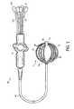
FIG. 1 is a top plan view of a catheter of the present invention, with a basket-shaped electrode assembly with independently controlled spines in an expanded configuration, according to one embodiment. -
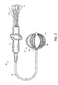
FIG. 2 is a schematic view of the basket-shaped electrode assembly ofFIG. 1 in which one spine is positioned relatively more distally, according to one embodiment. -
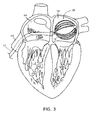
FIG. 3 is a schematic view of a basket-shaped electrode assembly within the left atrium, according to one embodiment. -
FIG. 4 is a schematic view of the basket-shaped electrode assembly ofFIG. 3 , in which one spine is positioned relatively more distally to increase contact with atrial tissue, according to one embodiment. -
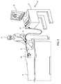
FIG. 5 is a schematic illustration of an invasive medical procedure using a basket-shaped electrode assembly with independently controlled spines, according to one embodiment. - At the outset, it is to be understood that this disclosure is not limited to particularly exemplified materials, architectures, routines, methods or structures as such may vary. Thus, although a number of such options, similar or equivalent to those described herein, can be used in the practice or embodiments of this disclosure, the preferred materials and methods are described herein.
- It is also to be understood that the terminology used herein is for the purpose of describing particular embodiments of this disclosure only and is not intended to be limiting.
- The detailed description set forth below in connection with the appended drawings is intended as a description of exemplary embodiments of the present disclosure and is not intended to represent the only exemplary embodiments in which the present disclosure can be practiced. The term "exemplary" used throughout this description means "serving as an example, instance, or illustration," and should not necessarily be construed as preferred or advantageous over other exemplary embodiments. The detailed description includes specific details for the purpose of providing a thorough understanding of the exemplary embodiments of the specification. It will be apparent to those skilled in the art that the exemplary embodiments of the specification may be practiced without these specific details. In some instances, well known structures and devices are shown in block diagram form in order to avoid obscuring the novelty of the exemplary embodiments presented herein.
- For purposes of convenience and clarity only, directional terms, such as top, bottom, left, right, up, down, over, above, below, beneath, rear, back, and front, may be used with respect to the accompanying drawings. These and similar directional terms should not be construed to limit the scope of the disclosure in any manner.
- Unless defined otherwise, all technical and scientific terms used herein have the same meaning as commonly understood by one having ordinary skill in the art to which the disclosure pertains.
- Finally, as used in this specification and the appended claims, the singular forms "a, "an" and "the" include plural referents unless the content clearly dictates otherwise.
- Certain types of electrical activity within a heart chamber are not cyclical. Examples include arterial flutter or arterial fibrillation, and ventricular tachycardia originating in scars in the wall of the ventricle that have resulted from infarcts. Such electrical activity is random from beat to beat. To analyze or 'map' this type of electrical activity, it is desirable to obtain the 'picture' as quickly as possible, such as within one heartbeat. In other words, all the points of the map or picture may be obtained simultaneously within one-tenth of a second. According to the techniques of this disclosure, a basket catheter with an electrode assembly of individually controlled spines may conform more closely to the anatomy of the patient's heart in order to accurately map this electrical activity.
- As shown in
FIG. 1 , thecatheter 10 may include anelongated catheter body 12, with acontrol handle 14 at its proximal end. A basket-shaped electrode assembly 16 may be located at the distal end of catheter body, and may be formed from a plurality ofspines 18, each carryingmultiple electrodes 20, mounted at the distal end of thecatheter body 12. Thecatheter body 12 comprises an elongated tubular construction having a single, axial or central lumen (not shown), but can optionally have multiple lumens if desired. To enable accurate mapping of electrical signals, for example to detect most or substantially all of the electrical function of the right or left atrium in as little as a single heartbeat, it may be desirable to provide an array of electrodes. As such, numbers ofspines 18 employed may be five to twelve or any other suitable number.Spines 18 may be evenly or unevenly distributed radially. Further, eachspine 18 may includemultiple electrodes 20, such as approximately five to thirty electrodes per spine, although other numbers can be employed depending on the application. Similarly, the electrodes may be evenly distributed along the spine or may be skewed proximally, centrally or distally to facilitate analysis of the measured electrical signals. - In one aspect,
spines 18 may include a material, such as a shape memory material as described below, that facilitates assuming an expanded configuration to bringelectrodes 20 into contact or closer proximity with tissue lining the walls of the cavity in which basket-shapedelectrode assembly 16 is deployed. Notably, as shown inFIG. 1 , in oneembodiment spines 18 may have a pre-shaped configuration in which they bow radially outwards from the longitudinal axis ofcatheter 10.Spines 18 may be sized appropriately depending on the patient's anatomy to provide a close fit to the area of the patient being investigated, such as the right or left atria. At the proximal end of basket-shapedelectrode assembly 16,spines 18 are freed from the constraint of being disposed withincatheter body 12 and the distal ends ofspines 18 may be secured together, such as bydistal cap 24. As such,spines 18 may bow outwards from the longitudinal axis ofcatheter 10 into the expanded configuration. - According to the techniques of this disclosure, each
spine 18 may be individually controllable. As shown,spines 18 are routed throughcatheter body 12 so that they extend to the proximal end of catheter and may terminate inactuators 22 to allow manipulation of eachspine 18 to adjust its position longitudinally relative tocatheter body 12. When a spine is moved relatively distally in the longitudinal direction, a greater length emerges fromcatheter body 12 and is freed from constraint. The distal end of basket-shapedelectrode assembly 16 is held in relative position by the remaining spines, or any other suitable mechanism such as a central wire. As a result, the spine being advanced longitudinally bows outwards to a greater degree. Correspondingly, retraction of a spine relative to the others decreases the degree of outward bow.Actuators 22 may also provide suitable connections for leads coupled toelectrodes 20. Thus, each spine has a corresponding actuator, such asspine 18a andactuator 22a as indicated. Longitudinal movement of eachspine 18 with respect tocatheter body 12 may be used tailor the degree to which each spine bows outward in order to more closely conform to the surrounding tissue. As such, the degree of contact with which one ormore electrodes 20 of a given spine engage the walls of the cavity in which basket-shapedelectrode assembly 16 is positioned may be adjusted as desired. - A schematic illustration of this operation is depicted in
FIG. 2 . In comparison to the configuration shown inFIG. 1 , one spine,spine 18a, has been advanced longitudinally relative tocatheter body 12, such as by manipulation ofactuator 18a. As discussed above, this causes the portion ofspine 18a in basket-shapedelectrode assembly 16 to deflect further outwards from the longitudinal axis. Although not shown, relative motion ofspine 18a in the proximal direction may provide the opposite result and reduce the amount of outward deflection. Correspondingly, the relative position of eachspine 18 may be adjusted as desired in order to achieve a greater degree of contact with and/or more closely conform to the tissue forming the surrounding walls. - As depicted in
FIG. 1 , eachspine 18 may comprise a core flexible wire 26 (shown in phantom) with a non-conductive covering 28 on which one or more of thering electrodes 20 are mounted. In an embodiment, theflexible wires 26 may be formed from a shape memory material to facilitate the transition between expanded and collapsed configurations and thenon-conductive coverings 28 may each comprise a biocompatible plastic tubing, such as polyurethane or polyimide tubing. For example, nickel-titanium alloys known as nitinol may be used. At body temperature, nitinol wire is flexible and elastic and, like most metals, nitinol wires deform when subjected to minimal force and return to their shape in the absence of that force. Nitinol belongs to a class of materials called Shaped Memory Alloys (SMA) that have interesting mechanical properties beyond flexibility and elasticity, including shape memory and superelasticity which allow nitinol to have a "memorized shape" that is dependent on its temperature phases. The austenite phase is nitinol's stronger, higher-temperature phase, with a simple cubic crystalline structure. Superelastic behavior occurs in this phase (over a 50°-60°C temperature spread). Correspondingly, the martensite phase is a relatively weaker, lower-temperature phase with a twinned crystalline structure. When a nitinol material is in the martensite phase, it is relatively easily deformed and will remain deformed. However, when heated above its austenite transition temperature, the nitinol material will return to its pre-deformed shape, producing the "shape memory" effect. The temperature at which nitinol starts to transform to austenite upon heating is referred to as the "As" temperature. The temperature at which nitinol has finished transforming to austenite upon heating is referred to as the "Af" temperature. Accordingly, basket-shapedelectrode assembly 16 may have a three dimensional shape that can be easily collapsed to be fed into a guiding sheath and then readily returned to its expanded shape memory configuration upon delivery to the desired region of the patient upon removal of the guiding sheath. - Alternatively, in some embodiments the
spines 18 can be designed without the internalflexible wire 26 if a sufficiently rigid nonconductive material is used for the non-conductive covering 28 to permit radial expansion of the basket-shapedelectrode assembly 16, so long as the spine has an outer surface that is non-conductive over at least a part of its surface for mounting of thering electrodes 20. - The
catheter body 12 is flexible, i.e., bendable, but substantially non-compressible along its length. Thecatheter body 12 can be of any suitable construction and made of any suitable material. One construction comprises an outer wall made of polyurethane or PEBAX® (polyether block amide). The outer wall comprises an imbedded braided mesh of stainless steel or the like to increase torsional stiffness of thecatheter body 12 so that, when the control handle 14 is rotated, the distal end of the catheter body will rotate in a corresponding manner. The outer diameter of thecatheter body 12 is not critical, but generally should be as small as possible and may be no more than about 10 french depending on the desired application. Likewise the thickness of the outer wall is not critical, but may be thin enough so that the central lumen can accommodate a puller wire, lead wires, sensor cables and any other wires, cables or tubes. If desired, the inner surface of the outer wall is lined with a stiffening tube (not shown) to provide improved torsional stability. An example of a catheter body construction suitable for use in connection with the present invention is described and depicted inU.S. Patent No. 6,064,905 , the entire disclosure of which is incorporated herein by reference. - In some embodiments, each
spine 18 may include cabling with built-in or embedded lead wires for theelectrodes 20 carried by the spine as described inU.S. Patent Publication No. 2014/0309512, published October 16, 2014 , entitled HIGH DENSITY ELECTRODE STRUCTURE, andU.S. Patent Publication No. 2014/0305699, published October 16, 2014 , entitled CONNECTION OF ELECTRODES TO WIRES COILED ON A CORE, the entire disclosures of which are hereby incorporated by reference. - In one aspect, an electrophysiologist may introduce a guiding sheath, guidewire and dilator into the patient, as is generally known in the art. Examples of suitable guiding sheaths for use in connection with the inventive catheter are the PREFACE™ Braided Guiding Sheath (commercially available from Biosense Webster, Inc., Diamond Bar, CA) and the DiRex™ Guiding Sheath (commercially available from BARD, Murray Hill, NJ). The guidewire is inserted, the dilator is removed, and the catheter is introduced through the guiding sheath whereby the guidewire lumen in the expander permits the catheter to pass over the guidewire. In one exemplary procedure as depicted in
FIG. 3 , the catheter is first introduced to the right atrium (RA) via the inferior vena cava (IVC), where it passes through the septum (S) in order to reach the left atrium (LA). - As will be appreciated, the guiding sheath covers the
spines 18 of the basket-shapedelectrode assembly 16 in a collapsed position so that the entire catheter can be passed through the patient's vasculature to the desired location. Once the distal end of the catheter reaches the desired location, e.g., the left atrium as shown, the guiding sheath is withdrawn to expose the basket-shapedelectrode assembly 16. Once the guiding sheath is withdrawn,spines 18 flex outwardly to assume their preshaped expanded configuration. As shown inFIG. 3 , when eachspine 18 is positioned in approximately the same longitudinal position with respect tocatheter body 12, basket-shapedelectrode assembly 16 has an overall shape similar to conventional basket catheters. However, as can be seen, basket-shapedelectrode assembly 16 in this conformation may not conform optimally to the irregularly shaped, non-spherical left atrium. As such, at least some of the electrodes may be far enough away from areas of the tissue to provide accurate measurement of electrical signals. - Correspondingly, each
spine 18 may be individually controlled as described above to provide improved conformation to the region in which basket-shapedelectrode assembly 16 is deployed. As schematically shown inFIG. 4 ,spine 18a has been advanced longitudinally, causing it to bow outwards to a greater degree which brings it into closer conformance with the tissue being investigated. Likewise, the electrodes onspine 18a may be in closer proximity and/or more electrodes may be in contact with the tissue in order to more accurately measure electrical signals. Similarly, eachspine 18 may be individually manipulated to more closely conform to the surrounding tissue. - When basket-shaped
electrode assembly 16 has been positioned and the relative longitudinal position of one ormore spines 18 has been adjusted as desired, the electrophysiologist may map local activation time and/or ablate usingelectrodes 20, which can guide the electrophysiologist in diagnosing and providing therapy to the patient. The catheter may include one or more reference ring electrodes mounted on the catheter body and/or one or more reference electrodes may be placed outside the body of the patient. By using the inventive catheter with the one or more electrodes on the basket-shapedelectrode assembly 16 brought into closer proximity or contact with tissue by adjusting the longitudinal position of one ormore spines 18, the electrophysiologist can obtain a true anatomy of a cavernous region of the heart, including an atrium, by measuring less points than with traditional catheters, allowing a more rapid mapping of the region. - To help illustrate use of basket-shaped
electrode assembly 16 with individuallycontrollable spines 18,FIG. 5 is a schematic depiction of an invasive medical procedure, according to an embodiment of the present invention.Catheter 10, with the basket-shaped electrode assembly 16 (not shown in this view) at the distal end may have aconnector 50 for coupling the wires fromactuators 22 and their associated electrodes 20 (not shown in this view) to aconsole 52 for recording and analyzing the signals they detect. Anelectrophysiologist 54 may insert thecatheter 10 into a patient 56 in order to acquire electropotential signals from theheart 58 of the patient. The professional uses the control handle 14 attached to the catheter in order to perform the insertion.Console 52 may include aprocessing unit 60 which analyzes the received signals, and which may present results of the analysis on adisplay 62 attached to the console. The results are typically in the form of a map, numerical displays, and/or graphs derived from the signals. - In a further aspect, the
processing unit 60 may also receive signals from one ormore location sensors 30 provided near a distal end of thecatheter 10 adjacent the basket-shapedelectrode assembly 16 as schematically indicated inFIG. 1 . The sensor(s) may each comprise a magnetic-field-responsive coil or a plurality of such coils. Using a plurality of coils enables six-dimensional position and orientation coordinates to be determined. The sensors may therefore generate electrical position signals in response to the magnetic fields from external coils, thereby enablingprocessor 60 to determine the position, (e.g., the location and orientation) of the distal end ofcatheter 10 within the heart cavity. The electrophysiologist may then view the position of the basket-shapedelectrode assembly 16 on an image the patient's heart on thedisplay 62. By way of example, this method of position sensing may be implemented using the CARTO™ system, produced by Biosense Webster Inc. (Diamond Bar, Calif.) and is described in detail inU.S. Patent Nos. 5,391,199 ,6,690,963 ,6,484,118 ,6,239,724 ,6,618,612 and6,332,089 , inPCT Patent Publication WO 96/05768 U.S. Patent Application Publications 2002/0065455 A1 ,2003/0120150 A1 and2004/0068178 A1 , whose disclosures are all incorporated herein by reference. As will be appreciated, other location sensing techniques may also be employed. If desired, at least two location sensors may be positioned proximally and distally of the basket-shapedelectrode assembly 16. The coordinates of the distal sensor relative to the proximal sensor may be determined and, with other known information pertaining to the curvature of thespines 18 of the basket-shapedelectrode assembly 16 as dependent on their relative longitudinal position, used to find the positions of each of theelectrodes 20. - The preceding description has been presented with reference to presently disclosed embodiments of the invention. Workers skilled in the art and technology to which this invention pertains will appreciate that alterations and changes in the described structure may be practiced without meaningfully departing from the principal, spirit and scope of this invention. As understood by one of ordinary skill in the art, the drawings are not necessarily to scale. Accordingly, the foregoing description should not be read as pertaining only to the precise structures described and illustrated in the accompanying drawings, but rather should be read consistent with and as support to the following claims which are to have their fullest and fair scope.
-
- 1. A method for mapping a cavity of the body comprising:
- providing an elongated catheter body having proximal and distal ends and at least one lumen therethrough and a basket-shaped electrode assembly at the distal end of the catheter body, the basket-shaped electrode assembly comprising a plurality of spines connected at their distal ends, each spine comprising a plurality of electrodes and extending through the lumen of the catheter body to the proximal end;
- introducing the distal end of the catheter into the cavity;
- expanding the basket-shaped electrode assembly from a collapsed configuration wherein the spines are arranged generally along a longitudinal axis of the catheter body to an expanded configuration, wherein each of the spines has a length unconstrained by the catheter body;
- independently controlling at least one of the spines to increase contact between at least a portion of the electrodes of the spine with tissue forming the cavity; and
- recording electrical data received from the at least a portion of the electrodes in contact with the tissue.
- 2. The method of aspect 1, wherein independently controlling at least one of the spines comprises adjusting a longitudinal position of the at least one spine relative to the catheter body.
- 3. The method of aspect 1, wherein the spines bow radially outwardly when in the expanded configuration.
- 4. The method of aspect 3, wherein independently controlling at least one of the spines comprises positioning the at least one spine relatively more distally to increase the unconstrained length and cause the at least one spine to bow outwards to a greater degree.
- 5. The method of aspect 3 wherein independently controlling at least one of the spines comprises positioning the at least one spine relatively more proximally to decrease the unconstrained length and cause the at least one spine to bow outwards to a lesser degree.
- 6. The method of aspect 1, wherein the cavity of the body is an atrium of the heart.
- 7. The method of aspect 1, further comprising independently controlling a plurality of the spines.
Claims (9)
- A catheter comprising an elongated catheter body having proximal and distal ends and at least one lumen therethrough and a basket-shaped electrode assembly at the distal end of the catheter body, the basket-shaped electrode assembly comprising a plurality of spines connected at their distal ends, each spine comprising a plurality of electrodes and extending through the lumen of the catheter body to the proximal end, wherein each spine is independently controlled.
- The catheter of claim 1, wherein each spine is independently controlled by adjusting a longitudinal position relative to the catheter body.
- The catheter of claim 1, wherein the basket-shaped electrode assembly has an expanded configuration in which each of the spines bow radially outwardly with a length unconstrained by the catheter body and a collapsed configuration in which the spines are arranged generally along a longitudinal axis of the catheter body.
- The catheter of claim 3, wherein each spine is in a retracted position within respect to the catheter body when in the collapsed configuration.
- The catheter of claim 3, wherein each of the spines are configured to bow outwards to a greater degree when positioned relatively more distally to increase the unconstrained length when the basket-shaped electrode assembly is in the expanded configuration.
- The catheter of claim 3, wherein each of the spines may bow outwards to a lesser degree when positioned relatively more proximally to decrease the unconstrained length when the basket-shaped electrode assembly is in the expanded configuration.
- The catheter of claim 1, wherein each spine comprises an actuator at a proximal end.
- The catheter of claim 7, wherein each actuator comprises a connector for coupling leads to the electrodes on the spine.
- The catheter of claim 1, wherein each spine comprises a shape memory material.
Applications Claiming Priority (1)
| Application Number | Priority Date | Filing Date | Title |
|---|---|---|---|
| US14/853,668 US10987045B2 (en) | 2015-09-14 | 2015-09-14 | Basket catheter with individual spine control |
Publications (2)
| Publication Number | Publication Date |
|---|---|
| EP3141183A1 true EP3141183A1 (en) | 2017-03-15 |
| EP3141183B1 EP3141183B1 (en) | 2023-06-07 |
Family
ID=56939881
Family Applications (1)
| Application Number | Title | Priority Date | Filing Date |
|---|---|---|---|
| EP16188474.7A Active EP3141183B1 (en) | 2015-09-14 | 2016-09-13 | Basket catheter with individual spine control |
Country Status (8)
| Country | Link |
|---|---|
| US (1) | US10987045B2 (en) |
| EP (1) | EP3141183B1 (en) |
| JP (1) | JP2017056201A (en) |
| CN (1) | CN106510697A (en) |
| AU (1) | AU2016216556A1 (en) |
| CA (1) | CA2940507A1 (en) |
| IL (1) | IL247384B (en) |
| RU (1) | RU2016136669A (en) |
Cited By (1)
| Publication number | Priority date | Publication date | Assignee | Title |
|---|---|---|---|---|
| EP4137080A1 (en) * | 2021-08-16 | 2023-02-22 | Biosense Webster (Israel) Ltd. | Catheter having electrodes with adjustable size |
Families Citing this family (17)
| Publication number | Priority date | Publication date | Assignee | Title |
|---|---|---|---|---|
| EP3340916B1 (en) | 2015-10-21 | 2020-12-02 | St. Jude Medical, Cardiology Division, Inc. | High density electrode mapping catheter |
| WO2018080985A1 (en) | 2016-10-24 | 2018-05-03 | St. Jude Medical, Cardiology Division, Inc. | Catheter insertion devices |
| US11647935B2 (en) | 2017-07-24 | 2023-05-16 | St. Jude Medical, Cardiology Division, Inc. | Masked ring electrodes |
| CN111491582B (en) | 2017-11-28 | 2023-12-05 | 圣犹达医疗用品心脏病学部门有限公司 | Controlled inflatable catheter |
| US11642063B2 (en) | 2018-08-23 | 2023-05-09 | St. Jude Medical, Cardiology Division, Inc. | Curved high density electrode mapping catheter |
| US11918762B2 (en) | 2018-10-03 | 2024-03-05 | St. Jude Medical, Cardiology Division, Inc. | Reduced actuation force electrophysiology catheter handle |
| US11045628B2 (en) | 2018-12-11 | 2021-06-29 | Biosense Webster (Israel) Ltd. | Balloon catheter with high articulation |
| US11850051B2 (en) | 2019-04-30 | 2023-12-26 | Biosense Webster (Israel) Ltd. | Mapping grid with high density electrode array |
| WO2021011751A1 (en) * | 2019-07-17 | 2021-01-21 | Boston Scientific Scimed, Inc. | Devices, systems, and methods for accessing a body lumen |
| US11950930B2 (en) | 2019-12-12 | 2024-04-09 | Biosense Webster (Israel) Ltd. | Multi-dimensional acquisition of bipolar signals from a catheter |
| US11517218B2 (en) | 2019-12-20 | 2022-12-06 | Biosense Webster (Israel) Ltd. | Selective graphical presentation of electrophysiological parameters |
| US11950840B2 (en) | 2020-09-22 | 2024-04-09 | Biosense Webster (Israel) Ltd. | Basket catheter having insulated ablation electrodes |
| US11950841B2 (en) | 2020-09-22 | 2024-04-09 | Biosense Webster (Israel) Ltd. | Basket catheter having insulated ablation electrodes and diagnostic electrodes |
| US11918383B2 (en) | 2020-12-21 | 2024-03-05 | Biosense Webster (Israel) Ltd. | Visualizing performance of catheter electrodes |
| CN113729924B (en) * | 2021-09-30 | 2023-10-20 | 上海睿刀医疗科技有限公司 | Electrode catheter and ablation device |
| US20230190363A1 (en) | 2021-12-22 | 2023-06-22 | Biosense Webster (Israel) Ltd. | Irreversible Electroporation with Shorted Electrodes |
| US20230190357A1 (en) | 2021-12-22 | 2023-06-22 | Biosense Webster (Israel) Ltd. | Compact Basket Probe |
Citations (19)
| Publication number | Priority date | Publication date | Assignee | Title |
|---|---|---|---|---|
| US4699147A (en) * | 1985-09-25 | 1987-10-13 | Cordis Corporation | Intraventricular multielectrode cardial mapping probe and method for using same |
| US5391199A (en) | 1993-07-20 | 1995-02-21 | Biosense, Inc. | Apparatus and method for treating cardiac arrhythmias |
| WO1996005768A1 (en) | 1994-08-19 | 1996-02-29 | Biosense, Inc. | Medical diagnosis, treatment and imaging systems |
| US5772590A (en) | 1992-06-30 | 1998-06-30 | Cordis Webster, Inc. | Cardiovascular catheter with laterally stable basket-shaped electrode array with puller wire |
| US5908446A (en) * | 1994-07-07 | 1999-06-01 | Cardiac Pathways Corporation | Catheter assembly, catheter and multi-port introducer for use therewith |
| US6064905A (en) | 1998-06-18 | 2000-05-16 | Cordis Webster, Inc. | Multi-element tip electrode mapping catheter |
| US6174318B1 (en) * | 1998-04-23 | 2001-01-16 | Scimed Life Systems, Inc. | Basket with one or more moveable legs |
| US6239724B1 (en) | 1997-12-30 | 2001-05-29 | Remon Medical Technologies, Ltd. | System and method for telemetrically providing intrabody spatial position |
| US6332089B1 (en) | 1996-02-15 | 2001-12-18 | Biosense, Inc. | Medical procedures and apparatus using intrabody probes |
| US20020065455A1 (en) | 1995-01-24 | 2002-05-30 | Shlomo Ben-Haim | Medical diagnosis, treatment and imaging systems |
| US6484118B1 (en) | 2000-07-20 | 2002-11-19 | Biosense, Inc. | Electromagnetic position single axis system |
| US20030120150A1 (en) | 2001-12-21 | 2003-06-26 | Assaf Govari | Wireless position sensor |
| US6618612B1 (en) | 1996-02-15 | 2003-09-09 | Biosense, Inc. | Independently positionable transducers for location system |
| US20040068178A1 (en) | 2002-09-17 | 2004-04-08 | Assaf Govari | High-gradient recursive locating system |
| US6748255B2 (en) | 2001-12-14 | 2004-06-08 | Biosense Webster, Inc. | Basket catheter with multiple location sensors |
| US20050119647A1 (en) * | 2001-05-01 | 2005-06-02 | He Ding S. | Method and apparatus for altering conduction properties in the heart and in adjacent vessels |
| US6973340B2 (en) | 2001-12-14 | 2005-12-06 | Biosense Webster, Inc. | Basket catheter with improved expansion mechanism |
| US20120209262A1 (en) * | 2004-05-17 | 2012-08-16 | C.R. Bard, Inc. | Method and apparatus for mapping and/or ablation of cardiac tissue |
| US20140309512A1 (en) | 2013-04-11 | 2014-10-16 | Biosense Webster (Israel), Ltd. | High density electrode structure |
Family Cites Families (24)
| Publication number | Priority date | Publication date | Assignee | Title |
|---|---|---|---|---|
| US5327889A (en) | 1992-12-01 | 1994-07-12 | Cardiac Pathways Corporation | Mapping and ablation catheter with individually deployable arms and method |
| US5239724A (en) | 1992-01-30 | 1993-08-31 | Spartan Tool | Mechanism for advancing a rotating cylindrical member |
| US5237996A (en) * | 1992-02-11 | 1993-08-24 | Waldman Lewis K | Endocardial electrical mapping catheter |
| KR100249998B1 (en) | 1992-03-24 | 2000-05-01 | 다카다 쥬이치로 | Seat belt retractor |
| US5255679A (en) | 1992-06-02 | 1993-10-26 | Cardiac Pathways Corporation | Endocardial catheter for mapping and/or ablation with an expandable basket structure having means for providing selective reinforcement and pressure sensing mechanism for use therewith, and method |
| WO1994007412A1 (en) | 1992-09-25 | 1994-04-14 | Ep Technologies, Inc. | Electrode support splines for cardiac systems |
| US5309910A (en) * | 1992-09-25 | 1994-05-10 | Ep Technologies, Inc. | Cardiac mapping and ablation systems |
| US5856091A (en) | 1993-03-18 | 1999-01-05 | Ludwig Institute For Cancer Research | Isolated nucleic acid sequence coding for a tumor rejection antigen precursor processed to at least one tumor rejection antigen presented by HLA-A2 |
| US5332089A (en) | 1993-06-23 | 1994-07-26 | Ivy Hill Corporation | Storage package for recording medium |
| US5607462A (en) | 1993-09-24 | 1997-03-04 | Cardiac Pathways Corporation | Catheter assembly, catheter and multi-catheter introducer for use therewith |
| EP1364677A3 (en) * | 1993-11-10 | 2006-12-27 | Medtronic, Inc. | Electrode array catheter |
| US5583889A (en) | 1994-07-08 | 1996-12-10 | Zenith Electronics Corporation | Trellis coded modulation system for HDTV |
| CA2198128A1 (en) | 1994-09-20 | 1996-03-28 | Graham John Bratton | Improved membrane |
| US5885278A (en) * | 1994-10-07 | 1999-03-23 | E.P. Technologies, Inc. | Structures for deploying movable electrode elements |
| US5722401A (en) * | 1994-10-19 | 1998-03-03 | Cardiac Pathways Corporation | Endocardial mapping and/or ablation catheter probe |
| US5618612A (en) | 1995-05-30 | 1997-04-08 | Huyck Licensco, Inc. | Press felt having fine base fabric |
| US5690963A (en) | 1995-06-30 | 1997-11-25 | The United States Of America As Represented By The Secretary Of The Navy | Freeze dried red blood cells |
| JP2002126096A (en) | 2000-10-27 | 2002-05-08 | Aisin Seiki Co Ltd | Catheter equipped with electrode |
| US8945116B2 (en) | 2004-05-17 | 2015-02-03 | Boston Scientific Scimed, Inc. | Mapping and ablation method for the treatment of ventricular tachycardia |
| US7377906B2 (en) | 2004-06-15 | 2008-05-27 | Biosense Webster, Inc. | Steering mechanism for bi-directional catheter |
| US8137308B2 (en) | 2008-09-16 | 2012-03-20 | Biosense Webster, Inc. | Catheter with adjustable deflection sensitivity |
| AU2012246723C9 (en) * | 2011-04-22 | 2014-08-28 | Topera, Inc. | Basket style cardiac mapping catheter having an atraumatic basket tip for detection of cardiac rhythm disorders |
| US8825130B2 (en) * | 2011-12-30 | 2014-09-02 | St. Jude Medical, Atrial Fibrillation Division, Inc. | Electrode support structure assemblies |
| US9204929B2 (en) * | 2013-09-16 | 2015-12-08 | Biosense Webster (Israel) Ltd. | Basket catheter with deflectable spine |
-
2015
- 2015-09-14 US US14/853,668 patent/US10987045B2/en active Active
-
2016
- 2016-08-16 AU AU2016216556A patent/AU2016216556A1/en not_active Withdrawn
- 2016-08-21 IL IL247384A patent/IL247384B/en active IP Right Grant
- 2016-08-26 CA CA2940507A patent/CA2940507A1/en not_active Abandoned
- 2016-09-13 EP EP16188474.7A patent/EP3141183B1/en active Active
- 2016-09-13 JP JP2016178298A patent/JP2017056201A/en active Pending
- 2016-09-13 RU RU2016136669A patent/RU2016136669A/en not_active Application Discontinuation
- 2016-09-14 CN CN201610822108.8A patent/CN106510697A/en active Pending
Patent Citations (21)
| Publication number | Priority date | Publication date | Assignee | Title |
|---|---|---|---|---|
| US4699147A (en) * | 1985-09-25 | 1987-10-13 | Cordis Corporation | Intraventricular multielectrode cardial mapping probe and method for using same |
| US5772590A (en) | 1992-06-30 | 1998-06-30 | Cordis Webster, Inc. | Cardiovascular catheter with laterally stable basket-shaped electrode array with puller wire |
| US5391199A (en) | 1993-07-20 | 1995-02-21 | Biosense, Inc. | Apparatus and method for treating cardiac arrhythmias |
| US5908446A (en) * | 1994-07-07 | 1999-06-01 | Cardiac Pathways Corporation | Catheter assembly, catheter and multi-port introducer for use therewith |
| WO1996005768A1 (en) | 1994-08-19 | 1996-02-29 | Biosense, Inc. | Medical diagnosis, treatment and imaging systems |
| US20020065455A1 (en) | 1995-01-24 | 2002-05-30 | Shlomo Ben-Haim | Medical diagnosis, treatment and imaging systems |
| US6690963B2 (en) | 1995-01-24 | 2004-02-10 | Biosense, Inc. | System for determining the location and orientation of an invasive medical instrument |
| US6618612B1 (en) | 1996-02-15 | 2003-09-09 | Biosense, Inc. | Independently positionable transducers for location system |
| US6332089B1 (en) | 1996-02-15 | 2001-12-18 | Biosense, Inc. | Medical procedures and apparatus using intrabody probes |
| US6239724B1 (en) | 1997-12-30 | 2001-05-29 | Remon Medical Technologies, Ltd. | System and method for telemetrically providing intrabody spatial position |
| US6174318B1 (en) * | 1998-04-23 | 2001-01-16 | Scimed Life Systems, Inc. | Basket with one or more moveable legs |
| US6064905A (en) | 1998-06-18 | 2000-05-16 | Cordis Webster, Inc. | Multi-element tip electrode mapping catheter |
| US6484118B1 (en) | 2000-07-20 | 2002-11-19 | Biosense, Inc. | Electromagnetic position single axis system |
| US20050119647A1 (en) * | 2001-05-01 | 2005-06-02 | He Ding S. | Method and apparatus for altering conduction properties in the heart and in adjacent vessels |
| US6748255B2 (en) | 2001-12-14 | 2004-06-08 | Biosense Webster, Inc. | Basket catheter with multiple location sensors |
| US6973340B2 (en) | 2001-12-14 | 2005-12-06 | Biosense Webster, Inc. | Basket catheter with improved expansion mechanism |
| US20030120150A1 (en) | 2001-12-21 | 2003-06-26 | Assaf Govari | Wireless position sensor |
| US20040068178A1 (en) | 2002-09-17 | 2004-04-08 | Assaf Govari | High-gradient recursive locating system |
| US20120209262A1 (en) * | 2004-05-17 | 2012-08-16 | C.R. Bard, Inc. | Method and apparatus for mapping and/or ablation of cardiac tissue |
| US20140309512A1 (en) | 2013-04-11 | 2014-10-16 | Biosense Webster (Israel), Ltd. | High density electrode structure |
| US20140305699A1 (en) | 2013-04-11 | 2014-10-16 | Biosense Webster (Israel) Ltd. | Connection of electrodes to wires coiled on a core |
Cited By (1)
| Publication number | Priority date | Publication date | Assignee | Title |
|---|---|---|---|---|
| EP4137080A1 (en) * | 2021-08-16 | 2023-02-22 | Biosense Webster (Israel) Ltd. | Catheter having electrodes with adjustable size |
Also Published As
| Publication number | Publication date |
|---|---|
| CN106510697A (en) | 2017-03-22 |
| EP3141183B1 (en) | 2023-06-07 |
| RU2016136669A (en) | 2018-03-16 |
| IL247384B (en) | 2021-02-28 |
| IL247384A0 (en) | 2016-12-29 |
| US10987045B2 (en) | 2021-04-27 |
| JP2017056201A (en) | 2017-03-23 |
| CA2940507A1 (en) | 2017-03-14 |
| US20170071544A1 (en) | 2017-03-16 |
| AU2016216556A1 (en) | 2017-03-30 |
Similar Documents
| Publication | Publication Date | Title |
|---|---|---|
| EP3141183B1 (en) | Basket catheter with individual spine control | |
| EP3141185A1 (en) | Convertible basket catheter | |
| EP3372150B1 (en) | Electrode assembly having spines with controlled flexibility | |
| US10575743B2 (en) | High electrode density basket catheter | |
| US10362991B2 (en) | Convertible basket catheter | |
| US10314505B2 (en) | Asymmetric basket catheter | |
| EP3222209A1 (en) | Dispersed irrigation configuration for catheter tip design | |
| EP3345563A1 (en) | Multi-electrode assembly with controlled folding mechanism | |
| EP3141184A1 (en) | Dual multiray electrode catheter | |
| EP3130283B1 (en) | High electrode density basket catheter | |
| EP3241517A1 (en) | Varying diameter catheter distal end design for decreased distal hub size |
Legal Events
| Date | Code | Title | Description |
|---|---|---|---|
| PUAI | Public reference made under article 153(3) epc to a published international application that has entered the european phase |
Free format text: ORIGINAL CODE: 0009012 |
|
| STAA | Information on the status of an ep patent application or granted ep patent |
Free format text: STATUS: THE APPLICATION HAS BEEN PUBLISHED |
|
| AK | Designated contracting states |
Kind code of ref document: A1 Designated state(s): AL AT BE BG CH CY CZ DE DK EE ES FI FR GB GR HR HU IE IS IT LI LT LU LV MC MK MT NL NO PL PT RO RS SE SI SK SM TR |
|
| AX | Request for extension of the european patent |
Extension state: BA ME |
|
| STAA | Information on the status of an ep patent application or granted ep patent |
Free format text: STATUS: REQUEST FOR EXAMINATION WAS MADE |
|
| 17P | Request for examination filed |
Effective date: 20170915 |
|
| RBV | Designated contracting states (corrected) |
Designated state(s): AL AT BE BG CH CY CZ DE DK EE ES FI FR GB GR HR HU IE IS IT LI LT LU LV MC MK MT NL NO PL PT RO RS SE SI SK SM TR |
|
| STAA | Information on the status of an ep patent application or granted ep patent |
Free format text: STATUS: EXAMINATION IS IN PROGRESS |
|
| STAA | Information on the status of an ep patent application or granted ep patent |
Free format text: STATUS: EXAMINATION IS IN PROGRESS |
|
| 17Q | First examination report despatched |
Effective date: 20200928 |
|
| STAA | Information on the status of an ep patent application or granted ep patent |
Free format text: STATUS: EXAMINATION IS IN PROGRESS |
|
| RAP3 | Party data changed (applicant data changed or rights of an application transferred) |
Owner name: BIOSENSE WEBSTER (ISRAEL) LTD. |
|
| GRAP | Despatch of communication of intention to grant a patent |
Free format text: ORIGINAL CODE: EPIDOSNIGR1 |
|
| STAA | Information on the status of an ep patent application or granted ep patent |
Free format text: STATUS: GRANT OF PATENT IS INTENDED |
|
| RIC1 | Information provided on ipc code assigned before grant |
Ipc: A61B 5/287 20210101ALI20221107BHEP Ipc: A61B 5/00 20060101AFI20221107BHEP |
|
| INTG | Intention to grant announced |
Effective date: 20221129 |
|
| GRAS | Grant fee paid |
Free format text: ORIGINAL CODE: EPIDOSNIGR3 |
|
| GRAA | (expected) grant |
Free format text: ORIGINAL CODE: 0009210 |
|
| STAA | Information on the status of an ep patent application or granted ep patent |
Free format text: STATUS: THE PATENT HAS BEEN GRANTED |
|
| AK | Designated contracting states |
Kind code of ref document: B1 Designated state(s): AL AT BE BG CH CY CZ DE DK EE ES FI FR GB GR HR HU IE IS IT LI LT LU LV MC MK MT NL NO PL PT RO RS SE SI SK SM TR |
|
| REG | Reference to a national code |
Ref country code: GB Ref legal event code: FG4D |
|
| REG | Reference to a national code |
Ref country code: CH Ref legal event code: EP Ref country code: AT Ref legal event code: REF Ref document number: 1572318 Country of ref document: AT Kind code of ref document: T Effective date: 20230615 Ref country code: DE Ref legal event code: R096 Ref document number: 602016079812 Country of ref document: DE |
|
| REG | Reference to a national code |
Ref country code: LT Ref legal event code: MG9D |
|
| REG | Reference to a national code |
Ref country code: NL Ref legal event code: MP Effective date: 20230607 |
|
| PG25 | Lapsed in a contracting state [announced via postgrant information from national office to epo] |
Ref country code: SE Free format text: LAPSE BECAUSE OF FAILURE TO SUBMIT A TRANSLATION OF THE DESCRIPTION OR TO PAY THE FEE WITHIN THE PRESCRIBED TIME-LIMIT Effective date: 20230607 Ref country code: NO Free format text: LAPSE BECAUSE OF FAILURE TO SUBMIT A TRANSLATION OF THE DESCRIPTION OR TO PAY THE FEE WITHIN THE PRESCRIBED TIME-LIMIT Effective date: 20230907 Ref country code: ES Free format text: LAPSE BECAUSE OF FAILURE TO SUBMIT A TRANSLATION OF THE DESCRIPTION OR TO PAY THE FEE WITHIN THE PRESCRIBED TIME-LIMIT Effective date: 20230607 |
|
| PGFP | Annual fee paid to national office [announced via postgrant information from national office to epo] |
Ref country code: IT Payment date: 20230810 Year of fee payment: 8 Ref country code: GB Payment date: 20230803 Year of fee payment: 8 |
|
| REG | Reference to a national code |
Ref country code: AT Ref legal event code: MK05 Ref document number: 1572318 Country of ref document: AT Kind code of ref document: T Effective date: 20230607 |
|
| PG25 | Lapsed in a contracting state [announced via postgrant information from national office to epo] |
Ref country code: RS Free format text: LAPSE BECAUSE OF FAILURE TO SUBMIT A TRANSLATION OF THE DESCRIPTION OR TO PAY THE FEE WITHIN THE PRESCRIBED TIME-LIMIT Effective date: 20230607 Ref country code: NL Free format text: LAPSE BECAUSE OF FAILURE TO SUBMIT A TRANSLATION OF THE DESCRIPTION OR TO PAY THE FEE WITHIN THE PRESCRIBED TIME-LIMIT Effective date: 20230607 Ref country code: LV Free format text: LAPSE BECAUSE OF FAILURE TO SUBMIT A TRANSLATION OF THE DESCRIPTION OR TO PAY THE FEE WITHIN THE PRESCRIBED TIME-LIMIT Effective date: 20230607 Ref country code: LT Free format text: LAPSE BECAUSE OF FAILURE TO SUBMIT A TRANSLATION OF THE DESCRIPTION OR TO PAY THE FEE WITHIN THE PRESCRIBED TIME-LIMIT Effective date: 20230607 Ref country code: HR Free format text: LAPSE BECAUSE OF FAILURE TO SUBMIT A TRANSLATION OF THE DESCRIPTION OR TO PAY THE FEE WITHIN THE PRESCRIBED TIME-LIMIT Effective date: 20230607 Ref country code: GR Free format text: LAPSE BECAUSE OF FAILURE TO SUBMIT A TRANSLATION OF THE DESCRIPTION OR TO PAY THE FEE WITHIN THE PRESCRIBED TIME-LIMIT Effective date: 20230908 |
|
| PGFP | Annual fee paid to national office [announced via postgrant information from national office to epo] |
Ref country code: FR Payment date: 20230808 Year of fee payment: 8 Ref country code: DE Payment date: 20230802 Year of fee payment: 8 |
|
| PG25 | Lapsed in a contracting state [announced via postgrant information from national office to epo] |
Ref country code: FI Free format text: LAPSE BECAUSE OF FAILURE TO SUBMIT A TRANSLATION OF THE DESCRIPTION OR TO PAY THE FEE WITHIN THE PRESCRIBED TIME-LIMIT Effective date: 20230607 |
|
| PG25 | Lapsed in a contracting state [announced via postgrant information from national office to epo] |
Ref country code: SK Free format text: LAPSE BECAUSE OF FAILURE TO SUBMIT A TRANSLATION OF THE DESCRIPTION OR TO PAY THE FEE WITHIN THE PRESCRIBED TIME-LIMIT Effective date: 20230607 |
|
| PG25 | Lapsed in a contracting state [announced via postgrant information from national office to epo] |
Ref country code: IS Free format text: LAPSE BECAUSE OF FAILURE TO SUBMIT A TRANSLATION OF THE DESCRIPTION OR TO PAY THE FEE WITHIN THE PRESCRIBED TIME-LIMIT Effective date: 20231007 |
|
| PG25 | Lapsed in a contracting state [announced via postgrant information from national office to epo] |
Ref country code: SM Free format text: LAPSE BECAUSE OF FAILURE TO SUBMIT A TRANSLATION OF THE DESCRIPTION OR TO PAY THE FEE WITHIN THE PRESCRIBED TIME-LIMIT Effective date: 20230607 Ref country code: SK Free format text: LAPSE BECAUSE OF FAILURE TO SUBMIT A TRANSLATION OF THE DESCRIPTION OR TO PAY THE FEE WITHIN THE PRESCRIBED TIME-LIMIT Effective date: 20230607 Ref country code: RO Free format text: LAPSE BECAUSE OF FAILURE TO SUBMIT A TRANSLATION OF THE DESCRIPTION OR TO PAY THE FEE WITHIN THE PRESCRIBED TIME-LIMIT Effective date: 20230607 Ref country code: PT Free format text: LAPSE BECAUSE OF FAILURE TO SUBMIT A TRANSLATION OF THE DESCRIPTION OR TO PAY THE FEE WITHIN THE PRESCRIBED TIME-LIMIT Effective date: 20231009 Ref country code: IS Free format text: LAPSE BECAUSE OF FAILURE TO SUBMIT A TRANSLATION OF THE DESCRIPTION OR TO PAY THE FEE WITHIN THE PRESCRIBED TIME-LIMIT Effective date: 20231007 Ref country code: EE Free format text: LAPSE BECAUSE OF FAILURE TO SUBMIT A TRANSLATION OF THE DESCRIPTION OR TO PAY THE FEE WITHIN THE PRESCRIBED TIME-LIMIT Effective date: 20230607 Ref country code: CZ Free format text: LAPSE BECAUSE OF FAILURE TO SUBMIT A TRANSLATION OF THE DESCRIPTION OR TO PAY THE FEE WITHIN THE PRESCRIBED TIME-LIMIT Effective date: 20230607 Ref country code: AT Free format text: LAPSE BECAUSE OF FAILURE TO SUBMIT A TRANSLATION OF THE DESCRIPTION OR TO PAY THE FEE WITHIN THE PRESCRIBED TIME-LIMIT Effective date: 20230607 |
|
| PG25 | Lapsed in a contracting state [announced via postgrant information from national office to epo] |
Ref country code: PL Free format text: LAPSE BECAUSE OF FAILURE TO SUBMIT A TRANSLATION OF THE DESCRIPTION OR TO PAY THE FEE WITHIN THE PRESCRIBED TIME-LIMIT Effective date: 20230607 |