EP3124074A2 - Improved electrode design for minimally invasive procedure - Google Patents
Improved electrode design for minimally invasive procedure Download PDFInfo
- Publication number
- EP3124074A2 EP3124074A2 EP16184400.6A EP16184400A EP3124074A2 EP 3124074 A2 EP3124074 A2 EP 3124074A2 EP 16184400 A EP16184400 A EP 16184400A EP 3124074 A2 EP3124074 A2 EP 3124074A2
- Authority
- EP
- European Patent Office
- Prior art keywords
- electrode structure
- electrode
- backer
- mesh
- baroreflex
- Prior art date
- Legal status (The legal status is an assumption and is not a legal conclusion. Google has not performed a legal analysis and makes no representation as to the accuracy of the status listed.)
- Granted
Links
- 230000001976 improved effect Effects 0.000 title description 6
- 238000013461 design Methods 0.000 title description 3
- 238000002324 minimally invasive surgery Methods 0.000 title description 2
- 230000004913 activation Effects 0.000 claims abstract description 56
- 230000035581 baroreflex Effects 0.000 claims abstract description 56
- 238000000034 method Methods 0.000 claims abstract description 31
- 210000004204 blood vessel Anatomy 0.000 claims abstract description 25
- 239000000853 adhesive Substances 0.000 claims description 18
- 230000001070 adhesive effect Effects 0.000 claims description 18
- 230000003110 anti-inflammatory effect Effects 0.000 claims description 3
- 239000003795 chemical substances by application Substances 0.000 claims description 2
- 239000007943 implant Substances 0.000 abstract description 52
- 210000001774 pressoreceptor Anatomy 0.000 abstract description 50
- 108091008698 baroreceptors Proteins 0.000 abstract description 49
- 238000002560 therapeutic procedure Methods 0.000 abstract description 36
- 238000002513 implantation Methods 0.000 abstract description 11
- 239000000463 material Substances 0.000 abstract description 7
- 230000036772 blood pressure Effects 0.000 description 19
- 206010020772 Hypertension Diseases 0.000 description 16
- 210000002216 heart Anatomy 0.000 description 16
- 210000001326 carotid sinus Anatomy 0.000 description 14
- 238000013507 mapping Methods 0.000 description 11
- 230000004044 response Effects 0.000 description 11
- 230000000638 stimulation Effects 0.000 description 11
- 206010019280 Heart failures Diseases 0.000 description 10
- 210000004556 brain Anatomy 0.000 description 10
- 108020003175 receptors Proteins 0.000 description 9
- 210000005036 nerve Anatomy 0.000 description 8
- 230000000747 cardiac effect Effects 0.000 description 7
- 230000006870 function Effects 0.000 description 7
- 230000001960 triggered effect Effects 0.000 description 7
- 208000024172 Cardiovascular disease Diseases 0.000 description 6
- 230000002644 neurohormonal effect Effects 0.000 description 6
- 210000001519 tissue Anatomy 0.000 description 6
- 230000002792 vascular Effects 0.000 description 6
- 239000008280 blood Substances 0.000 description 5
- 210000004369 blood Anatomy 0.000 description 5
- 230000000694 effects Effects 0.000 description 5
- 210000003734 kidney Anatomy 0.000 description 5
- 230000033001 locomotion Effects 0.000 description 5
- 210000000056 organ Anatomy 0.000 description 5
- DGAQECJNVWCQMB-PUAWFVPOSA-M Ilexoside XXIX Chemical compound C[C@@H]1CC[C@@]2(CC[C@@]3(C(=CC[C@H]4[C@]3(CC[C@@H]5[C@@]4(CC[C@@H](C5(C)C)OS(=O)(=O)[O-])C)C)[C@@H]2[C@]1(C)O)C)C(=O)O[C@H]6[C@@H]([C@H]([C@@H]([C@H](O6)CO)O)O)O.[Na+] DGAQECJNVWCQMB-PUAWFVPOSA-M 0.000 description 4
- 238000013459 approach Methods 0.000 description 4
- 238000012986 modification Methods 0.000 description 4
- 230000004048 modification Effects 0.000 description 4
- 230000008569 process Effects 0.000 description 4
- 230000009467 reduction Effects 0.000 description 4
- 229910052708 sodium Inorganic materials 0.000 description 4
- 239000011734 sodium Substances 0.000 description 4
- 238000011282 treatment Methods 0.000 description 4
- 230000008859 change Effects 0.000 description 3
- 230000009849 deactivation Effects 0.000 description 3
- 230000001667 episodic effect Effects 0.000 description 3
- 238000010348 incorporation Methods 0.000 description 3
- 230000001965 increasing effect Effects 0.000 description 3
- 230000007246 mechanism Effects 0.000 description 3
- 210000000653 nervous system Anatomy 0.000 description 3
- 230000000737 periodic effect Effects 0.000 description 3
- 230000004936 stimulating effect Effects 0.000 description 3
- 210000005166 vasculature Anatomy 0.000 description 3
- XLYOFNOQVPJJNP-UHFFFAOYSA-N water Substances O XLYOFNOQVPJJNP-UHFFFAOYSA-N 0.000 description 3
- 230000009471 action Effects 0.000 description 2
- 210000005249 arterial vasculature Anatomy 0.000 description 2
- 210000002565 arteriole Anatomy 0.000 description 2
- 210000001367 artery Anatomy 0.000 description 2
- 210000003403 autonomic nervous system Anatomy 0.000 description 2
- 230000017531 blood circulation Effects 0.000 description 2
- 230000002612 cardiopulmonary effect Effects 0.000 description 2
- 210000001715 carotid artery Anatomy 0.000 description 2
- 230000008602 contraction Effects 0.000 description 2
- 230000008878 coupling Effects 0.000 description 2
- 238000010168 coupling process Methods 0.000 description 2
- 238000005859 coupling reaction Methods 0.000 description 2
- 230000006378 damage Effects 0.000 description 2
- 230000034994 death Effects 0.000 description 2
- 238000002474 experimental method Methods 0.000 description 2
- 210000001932 glossopharyngeal nerve Anatomy 0.000 description 2
- 230000036541 health Effects 0.000 description 2
- 210000000412 mechanoreceptor Anatomy 0.000 description 2
- 230000003680 myocardial damage Effects 0.000 description 2
- 210000001640 nerve ending Anatomy 0.000 description 2
- 230000007383 nerve stimulation Effects 0.000 description 2
- 229910001000 nickel titanium Inorganic materials 0.000 description 2
- HLXZNVUGXRDIFK-UHFFFAOYSA-N nickel titanium Chemical compound [Ti].[Ti].[Ti].[Ti].[Ti].[Ti].[Ti].[Ti].[Ti].[Ti].[Ti].[Ni].[Ni].[Ni].[Ni].[Ni].[Ni].[Ni].[Ni].[Ni].[Ni].[Ni].[Ni].[Ni].[Ni] HLXZNVUGXRDIFK-UHFFFAOYSA-N 0.000 description 2
- 230000002093 peripheral effect Effects 0.000 description 2
- 230000011514 reflex Effects 0.000 description 2
- 239000000126 substance Substances 0.000 description 2
- 230000002459 sustained effect Effects 0.000 description 2
- 230000008700 sympathetic activation Effects 0.000 description 2
- 210000002820 sympathetic nervous system Anatomy 0.000 description 2
- 230000004865 vascular response Effects 0.000 description 2
- 201000001320 Atherosclerosis Diseases 0.000 description 1
- 108010027529 Bio-glue Proteins 0.000 description 1
- LFQSCWFLJHTTHZ-UHFFFAOYSA-N Ethanol Chemical compound CCO LFQSCWFLJHTTHZ-UHFFFAOYSA-N 0.000 description 1
- 206010020880 Hypertrophy Diseases 0.000 description 1
- 208000004880 Polyuria Diseases 0.000 description 1
- 208000007536 Thrombosis Diseases 0.000 description 1
- NRTOMJZYCJJWKI-UHFFFAOYSA-N Titanium nitride Chemical compound [Ti]#N NRTOMJZYCJJWKI-UHFFFAOYSA-N 0.000 description 1
- 206010047141 Vasodilatation Diseases 0.000 description 1
- NIXOWILDQLNWCW-UHFFFAOYSA-N acrylic acid group Chemical group C(C=C)(=O)O NIXOWILDQLNWCW-UHFFFAOYSA-N 0.000 description 1
- 230000003213 activating effect Effects 0.000 description 1
- 230000000202 analgesic effect Effects 0.000 description 1
- 229940127088 antihypertensive drug Drugs 0.000 description 1
- 210000002376 aorta thoracic Anatomy 0.000 description 1
- 230000004872 arterial blood pressure Effects 0.000 description 1
- 230000002567 autonomic effect Effects 0.000 description 1
- 230000009286 beneficial effect Effects 0.000 description 1
- 230000008901 benefit Effects 0.000 description 1
- 230000003115 biocidal effect Effects 0.000 description 1
- 230000002051 biphasic effect Effects 0.000 description 1
- 230000036765 blood level Effects 0.000 description 1
- 210000005242 cardiac chamber Anatomy 0.000 description 1
- 230000009084 cardiovascular function Effects 0.000 description 1
- 210000000748 cardiovascular system Anatomy 0.000 description 1
- 210000003169 central nervous system Anatomy 0.000 description 1
- 108091008690 chemoreceptors Proteins 0.000 description 1
- 238000004891 communication Methods 0.000 description 1
- 150000001875 compounds Chemical class 0.000 description 1
- 210000002808 connective tissue Anatomy 0.000 description 1
- 238000011161 development Methods 0.000 description 1
- 230000018109 developmental process Effects 0.000 description 1
- 235000005911 diet Nutrition 0.000 description 1
- 230000000378 dietary effect Effects 0.000 description 1
- HTXDPTMKBJXEOW-UHFFFAOYSA-N dioxoiridium Chemical compound O=[Ir]=O HTXDPTMKBJXEOW-UHFFFAOYSA-N 0.000 description 1
- 230000035619 diuresis Effects 0.000 description 1
- 230000002526 effect on cardiovascular system Effects 0.000 description 1
- 238000005516 engineering process Methods 0.000 description 1
- 230000003090 exacerbative effect Effects 0.000 description 1
- 210000001508 eye Anatomy 0.000 description 1
- 230000005802 health problem Effects 0.000 description 1
- 230000000004 hemodynamic effect Effects 0.000 description 1
- 239000002874 hemostatic agent Substances 0.000 description 1
- 238000003384 imaging method Methods 0.000 description 1
- 230000006872 improvement Effects 0.000 description 1
- 230000001939 inductive effect Effects 0.000 description 1
- 229910000457 iridium oxide Inorganic materials 0.000 description 1
- 208000017169 kidney disease Diseases 0.000 description 1
- 108091008704 mechanoreceptors Proteins 0.000 description 1
- 230000001404 mediated effect Effects 0.000 description 1
- 108091008709 muscle spindles Proteins 0.000 description 1
- 208000010125 myocardial infarction Diseases 0.000 description 1
- 208000031225 myocardial ischemia Diseases 0.000 description 1
- 210000004126 nerve fiber Anatomy 0.000 description 1
- 238000005457 optimization Methods 0.000 description 1
- 230000008701 parasympathetic activation Effects 0.000 description 1
- 230000001734 parasympathetic effect Effects 0.000 description 1
- 230000010412 perfusion Effects 0.000 description 1
- 239000002831 pharmacologic agent Substances 0.000 description 1
- 230000000144 pharmacologic effect Effects 0.000 description 1
- 230000037081 physical activity Effects 0.000 description 1
- 230000035790 physiological processes and functions Effects 0.000 description 1
- HWLDNSXPUQTBOD-UHFFFAOYSA-N platinum-iridium alloy Chemical compound [Ir].[Pt] HWLDNSXPUQTBOD-UHFFFAOYSA-N 0.000 description 1
- 229920000728 polyester Polymers 0.000 description 1
- 229920001296 polysiloxane Polymers 0.000 description 1
- -1 pressoreceptors Proteins 0.000 description 1
- 230000002265 prevention Effects 0.000 description 1
- 210000001147 pulmonary artery Anatomy 0.000 description 1
- 230000009103 reabsorption Effects 0.000 description 1
- 230000008672 reprogramming Effects 0.000 description 1
- 238000012827 research and development Methods 0.000 description 1
- 208000015658 resistant hypertension Diseases 0.000 description 1
- 230000029058 respiratory gaseous exchange Effects 0.000 description 1
- 230000000717 retained effect Effects 0.000 description 1
- 230000001953 sensory effect Effects 0.000 description 1
- 229910001285 shape-memory alloy Inorganic materials 0.000 description 1
- 230000011664 signaling Effects 0.000 description 1
- 230000000391 smoking effect Effects 0.000 description 1
- 210000002460 smooth muscle Anatomy 0.000 description 1
- 150000003431 steroids Chemical class 0.000 description 1
- 238000004381 surface treatment Methods 0.000 description 1
- 238000001356 surgical procedure Methods 0.000 description 1
- 230000004083 survival effect Effects 0.000 description 1
- 230000002889 sympathetic effect Effects 0.000 description 1
- 230000035488 systolic blood pressure Effects 0.000 description 1
- 230000001225 therapeutic effect Effects 0.000 description 1
- 238000002604 ultrasonography Methods 0.000 description 1
- 230000024883 vasodilation Effects 0.000 description 1
- 239000013585 weight reducing agent Substances 0.000 description 1
Images


Classifications
-
- A—HUMAN NECESSITIES
- A61—MEDICAL OR VETERINARY SCIENCE; HYGIENE
- A61N—ELECTROTHERAPY; MAGNETOTHERAPY; RADIATION THERAPY; ULTRASOUND THERAPY
- A61N1/00—Electrotherapy; Circuits therefor
- A61N1/02—Details
- A61N1/04—Electrodes
- A61N1/05—Electrodes for implantation or insertion into the body, e.g. heart electrode
- A61N1/0551—Spinal or peripheral nerve electrodes
- A61N1/0558—Anchoring or fixation means therefor
-
- A—HUMAN NECESSITIES
- A61—MEDICAL OR VETERINARY SCIENCE; HYGIENE
- A61N—ELECTROTHERAPY; MAGNETOTHERAPY; RADIATION THERAPY; ULTRASOUND THERAPY
- A61N1/00—Electrotherapy; Circuits therefor
- A61N1/18—Applying electric currents by contact electrodes
- A61N1/32—Applying electric currents by contact electrodes alternating or intermittent currents
- A61N1/36—Applying electric currents by contact electrodes alternating or intermittent currents for stimulation
- A61N1/3605—Implantable neurostimulators for stimulating central or peripheral nerve system
- A61N1/3606—Implantable neurostimulators for stimulating central or peripheral nerve system adapted for a particular treatment
- A61N1/36114—Cardiac control, e.g. by vagal stimulation
- A61N1/36117—Cardiac control, e.g. by vagal stimulation for treating hypertension
-
- A—HUMAN NECESSITIES
- A61—MEDICAL OR VETERINARY SCIENCE; HYGIENE
- A61N—ELECTROTHERAPY; MAGNETOTHERAPY; RADIATION THERAPY; ULTRASOUND THERAPY
- A61N1/00—Electrotherapy; Circuits therefor
- A61N1/18—Applying electric currents by contact electrodes
- A61N1/32—Applying electric currents by contact electrodes alternating or intermittent currents
- A61N1/36—Applying electric currents by contact electrodes alternating or intermittent currents for stimulation
- A61N1/3605—Implantable neurostimulators for stimulating central or peripheral nerve system
- A61N1/36128—Control systems
- A61N1/36135—Control systems using physiological parameters
- A61N1/36139—Control systems using physiological parameters with automatic adjustment
-
- A—HUMAN NECESSITIES
- A61—MEDICAL OR VETERINARY SCIENCE; HYGIENE
- A61N—ELECTROTHERAPY; MAGNETOTHERAPY; RADIATION THERAPY; ULTRASOUND THERAPY
- A61N1/00—Electrotherapy; Circuits therefor
- A61N1/18—Applying electric currents by contact electrodes
- A61N1/32—Applying electric currents by contact electrodes alternating or intermittent currents
- A61N1/36—Applying electric currents by contact electrodes alternating or intermittent currents for stimulation
- A61N1/3605—Implantable neurostimulators for stimulating central or peripheral nerve system
- A61N1/36128—Control systems
- A61N1/36146—Control systems specified by the stimulation parameters
- A61N1/3615—Intensity
- A61N1/3616—Voltage density or current density
-
- A—HUMAN NECESSITIES
- A61—MEDICAL OR VETERINARY SCIENCE; HYGIENE
- A61N—ELECTROTHERAPY; MAGNETOTHERAPY; RADIATION THERAPY; ULTRASOUND THERAPY
- A61N1/00—Electrotherapy; Circuits therefor
- A61N1/18—Applying electric currents by contact electrodes
- A61N1/32—Applying electric currents by contact electrodes alternating or intermittent currents
- A61N1/36—Applying electric currents by contact electrodes alternating or intermittent currents for stimulation
- A61N1/3605—Implantable neurostimulators for stimulating central or peripheral nerve system
- A61N1/36128—Control systems
- A61N1/36146—Control systems specified by the stimulation parameters
- A61N1/36167—Timing, e.g. stimulation onset
- A61N1/36171—Frequency
-
- A—HUMAN NECESSITIES
- A61—MEDICAL OR VETERINARY SCIENCE; HYGIENE
- A61N—ELECTROTHERAPY; MAGNETOTHERAPY; RADIATION THERAPY; ULTRASOUND THERAPY
- A61N1/00—Electrotherapy; Circuits therefor
- A61N1/18—Applying electric currents by contact electrodes
- A61N1/32—Applying electric currents by contact electrodes alternating or intermittent currents
- A61N1/36—Applying electric currents by contact electrodes alternating or intermittent currents for stimulation
- A61N1/3605—Implantable neurostimulators for stimulating central or peripheral nerve system
- A61N1/36128—Control systems
- A61N1/36146—Control systems specified by the stimulation parameters
- A61N1/36167—Timing, e.g. stimulation onset
- A61N1/36175—Pulse width or duty cycle
-
- A—HUMAN NECESSITIES
- A61—MEDICAL OR VETERINARY SCIENCE; HYGIENE
- A61N—ELECTROTHERAPY; MAGNETOTHERAPY; RADIATION THERAPY; ULTRASOUND THERAPY
- A61N1/00—Electrotherapy; Circuits therefor
- A61N1/18—Applying electric currents by contact electrodes
- A61N1/32—Applying electric currents by contact electrodes alternating or intermittent currents
- A61N1/36—Applying electric currents by contact electrodes alternating or intermittent currents for stimulation
- A61N1/3605—Implantable neurostimulators for stimulating central or peripheral nerve system
- A61N1/36128—Control systems
- A61N1/36146—Control systems specified by the stimulation parameters
- A61N1/36182—Direction of the electrical field, e.g. with sleeve around stimulating electrode
Definitions
- the present invention relates generally to baroreflex activation therapy devices and methods, and more particularly to an improved electrode design for use with an implant tool and procedure, as part of a baroreflex activation therapy system.
- Cardiovascular disease is a major contributor to patient illness and mortality. It also is a primary driver of health care expenditure, costing billions of dollars each year in the United States.
- Heart failure is the final common expression of a variety of cardiovascular disorders, including ischemic heart disease. It is characterized by an inability of the heart to pump enough blood to meet the body's needs and results in fatigue, reduced exercise capacity and poor survival. Heart failure results in the activation of a number of body systems to compensate for the heart's inability to pump sufficient blood. Many of these responses are mediated by an increase in the level of activation of the sympathetic nervous system, as well as by activation of multiple other neurohormonal responses.
- this sympathetic nervous system activation signals the heart to increase heart rate and force of contraction to increase the cardiac output; it signals the kidneys to expand the blood volume by retaining sodium and water; and it signals the arterioles to constrict to elevate the blood pressure.
- the cardiac, renal and vascular responses increase the workload of the heart, further accelerating myocardial damage and exacerbating the heart failure state. Accordingly, it is desirable to reduce the level of sympathetic nervous system activation in order to stop or at least minimize this vicious cycle and thereby treat or manage the heart failure.
- Hypertension or high blood pressure
- hypertension is a major cardiovascular disorder that is estimated to affect 65 million people in the United Sates alone. Hypertension occurs when the body's smaller blood vessels (arterioles) constrict, causing an increase in blood pressure. Because the blood vessels constrict, the heart must work harder to maintain blood flow at the higher pressures. Although the body may tolerate short periods of increased blood pressure, sustained hypertension may eventually result in damage to multiple body organs, including the kidneys, brain, eyes and other tissues, causing a variety of maladies associated therewith. The elevated blood pressure may also damage the lining of the blood vessels, accelerating the process of atherosclerosis and increasing the likelihood that a blood clot may develop. This could lead to a heart attack and/or stroke. Sustained high blood pressure may eventually result in an enlarged and damaged heart (hypertrophy), which may lead to heart failure.
- Hypertension is a leading cause of heart failure and stroke, is the primary cause of death for tens of thousands of patients per year, and is listed as a primary or contributing cause of death for hundreds of thousands of patients per year in the U.S. Accordingly, hypertension is a serious health problem demanding significant research and development for the treatment thereof. Hypertension remains a significant risk for patients and challenge for health care providers around the world despite improvements in awareness, prevention, treatment and control over the last 30 years. Patients with hypertension are encouraged to implement lifestyle modifications including weight reduction, adopting the DASH eating plan, reducing dietary sodium, increasing physical activity, and limiting alcohol consumption and smoking. A large number of pharmacologic treatments are also currently available to treat hypertension.
- carotid sinus nerve stimulation can negatively affect the patient's breathing patterns as well as blood circulation.
- the paucity of literature on carotid sinus nerve stimulation during time is reflective of this and the lack of any similar or alternate stimulation systems for the treatment of drug resistant hypertension.
- Baroreflex Activation Therapy utilizes electrical, mechanical, chemical, and/or other means of stimulation to activate one or more components of a patient's baroreflex system, such as baroreceptors.
- Baroreceptors are sensory nerve ends that are profusely distributed within the arterial walls of the major arteries, as well in the heart, aortic arch, carotid sinus or arteries, and in the low-pressure side of the vasculature such as the pulmonary artery and vena cava. Baroreceptor signals are used to activate a number of body systems which collectively may be referred to as the baroreflex system. Baroreceptors are connected to the brain via the nervous system, allowing the brain to detect changes in blood pressure, which is indicative of cardiac output.
- the baroreflex system activates a number of body systems, including the heart, kidneys, vessels, and other organs/tissues.
- Such natural activation of the baroreflex system generally corresponds to an increase in neurohormonal activity.
- the baroreflex system initiates a neurohormonal sequence that signals the heart to increase heart rate and increase contraction force in order to increase cardiac output, signals the kidneys to increase blood volume by retaining sodium and water, and signals the vessels to constrict to elevate blood pressure.
- the cardiac, renal and vascular responses increase blood pressure and cardiac output, and thus increase the workload of the heart. In a patient suffering from heart failure, this further accelerates myocardial damage and exacerbates the heart failure state.
- a baroreceptor activation device may be activated, deactivated or otherwise modulated to activate one or more baroreceptors and induce a baroreceptor signal or a change in the baroreceptor signal to thereby affect a change in the baroreflex system.
- the baroreceptor activation device may be activated, deactivated, or otherwise modulated continuously, periodically, or episodically.
- the baroreceptor activation device may utilize electrical as well as mechanical, thermal, chemical, biological, or a combination thereof to activate the baroreceptor.
- the baroreceptor may be activated directly, or activated indirectly via the adjacent vascular tissue. Activation of this reflex increases afferent electrical signals through the carotid sinus nerve (Hering's nerve, a branch of the glossopharyngeal nerve, cranial nerve IX) to the medullary brain centers that regulate autonomic tone. Increased afferent signals to these medullary centers cause a reduction in sympathetic tone and an increase in parasympathetic tone.
- peripheral activation of the baroreflex results in a physiologic response whereby blood pressure is controlled by mechanisms determined by the integrative action of the central nervous system action on all peripheral organs and blood vessels.
- the process of implanting a baroreflex activation device for delivering baroreflex therapy involves positioning the assembly such that the electrodes are properly situated against the arterial wall of the carotid sinus, and securing the electrode assembly to the artery so that the positioning is maintained.
- the process of adjusting and re-adjusting the position of the electrode assembly during implantation adds to the overall procedure time.
- Present-day procedures involve positioning and holding the electrode assembly in place with forceps, hemostat or similar tool while applying the stimulus and observing the response in the patient. Movement by as little as 1 mm can make a medically relevant difference in the effectiveness of the baroreceptor activation.
- mapping methods and techniques for implanting electrodes is disclosed in U.S. Patent No. 6,850,801 to Kieval et al.
- the positioning is a critical step, as the electrodes must direct as much energy as possible toward the baroreceptors for maximum effectiveness and efficiency.
- the energy source for the implanted baroreflex stimulation device is typically an on-board battery with finite capacity, and it is desirable to provide a lower energy source to ensure patient safety.
- a high-efficiency implantation will provide a longer battery life and correspondingly longer effective service life between surgeries because less energy will be required to achieve the needed degree of therapy.
- the position of the assembly is typically adjusted several times during the implantation procedure in order to optimize the baroreflex response.
- Another challenge related to the positioning process is the task of keeping track of previous desirable positions. Because positioning the electrode assembly is an optimization procedure, surgeons will tend to search for better positions until they have exhausted all reasonable alternative positions. Returning the electrode assembly to a previously-observed optimal position can be quite difficult and frustrating, especially under surgical conditions. Additionally, previous mapping approaches required large incisions to provide clearance for positioning and re-positioning of the electrode assembly.
- An implantable baroreflex activation system includes a control system having an implantable housing, an electrical lead, attachable to the control system, and an electrode structure.
- the electrode structure is near one end of the electrical lead, and includes a monopolar electrode, a backing material having an effective surface area larger than the electrode, and a releasable pivotable interface to mate with an implant tool.
- the electrode is configured for implantation on an outer surface of a blood vessel and the control system is programmed to deliver a baroreflex therapy via the monopolar electrode to a baroreceptor within a wall of the blood vessel.
- the present invention basically provides a number of devices, systems and methods by which the baroreflex system is activated to reduce excessive blood pressure, autonomic nervous system activity and neurohormonal activation.
- the present invention provides a number of devices, systems and methods by which baroreceptors may be activated, thereby indicating an increase in blood pressure and signaling the brain to reduce the body's blood pressure and level of sympathetic nervous system and neurohormonal activation, and increase parasympathetic nervous system activation, thus having a beneficial effect on the cardiovascular system and other body systems.
- FIG. 1 depicts a schematic illustration of baroreceptors 30 disposed in a generic vascular wall 40 and a schematic flow chart of the baroreflex system 50.
- Baroreceptors 30 are profusely distributed within the vascular walls discussed previously, and generally form an arbor 32.
- the baroreceptor arbor 32 comprises a plurality of baroreceptors 30, each of which transmits baroreceptor signals to the brain 52 via nerve 38.
- the baroreceptors 30 are so profusely distributed and arborized within the vascular wall 40 that discrete baroreceptor arbors 32 are not readily discernable.
- the baroreceptors 30 depicted in Figure 1 are primarily schematic for purposes of illustration and discussion.
- Baroreceptor signals in the arterial vasculature are used to activate a number of body systems which collectively may be referred to as the baroreflex system.
- the baroreflex system For the purposes of the present invention, it will be assumed that the "receptors" in the venous and cardiopulmonary vasculature and heart chambers function analogously to the baroreceptors in the arterial vasculature, but such assumption is not intended to limit the present invention in any way. In particular, the methods described herein will function and achieve at least some of the stated therapeutic objectives regardless of the precise and actual mechanism responsible for the result.
- the present invention may activate baroreceptors, mechanoreceptors, pressoreceptors, stretch receptors, chemoreceptors, or any other venous, heart, or cardiopulmonary receptors which affect the blood pressure, nervous system activity, and neurohormonal activity in a manner analogous to baroreceptors in the arterial vasculation.
- baroreceptors mechanoreceptors, pressoreceptors, stretch receptors, chemoreceptors, or any other venous, heart, or cardiopulmonary receptors which affect the blood pressure, nervous system activity, and neurohormonal activity in a manner analogous to baroreceptors in the arterial vasculation.
- baroreceptors mechanoreceptors, pressoreceptors, stretch receptors, chemoreceptors, or any other venous, heart, or cardiopulmonary receptors which affect the blood pressure, nervous system activity, and neurohormonal activity in a manner analogous to baroreceptors in the arterial vascul
- activation may be directed at any of these receptors and/or nerves and/or nerve endings from these receptors so long as they provide the desired effects.
- receptors will provide afferent signals, i.e., signals to the brain, which provide the blood pressure and/or volume information to the brain. This allows the brain to cause "reflex" changes in the autonomic nervous system, which in turn modulate organ activity to maintain desired hemodynamics and organ perfusion. Stimulation of the baroreflex system may be accomplished by stimulating such receptors, nerves, nerve fibers, or nerve endings, or any combination thereof.
- a baroreflex activation therapy system utilizing an improved electrode and lead arrangement generally include a control system, a baroreceptor activation device, a lead and a sensor (optional).
- a control system 60 may include a therapy block 61 comprising a processor 63 and a memory 62.
- Control system 60 is enclosed within a housing, or can, and is communicably coupled to baroreflex activation device 70 such as by way of electric control cable 72, or by wireless means such as radiofrequency or other forms of wireless communication.
- Cable 72 may include an optional attachment tab 73, which may be used to suture or otherwise attach cable 72 to a patient in order to provide strain relief to the electrode-tissue interface.
- Control system 60 includes a driver 66 to provide the desired power mode for the baroreceptor activation device 70.
- the driver 66 may comprise a power amplifier, pulse generator or the like to selectively deliver electrical control signals, and the cable 72 may comprise electrical lead(s).
- the electrical control signal generated by the driver 66 may be continuous, periodic, episodic or a combination thereof, as dictated by an algorithm contained in memory 62 of the control system 60.
- Continuous control signals include a constant pulse, a constant train of pulses, a triggered pulse and a triggered train of pulses.
- Periodic control signals include each of the continuous control signals described above which have a designated start time and a designated duration.
- Episodic control signals include each of the continuous control signals described above which are triggered by an episode.
- the control system memory 62 may contain data related to the sensor signal, the therapy signal, and/or values and commands provided by the input device 64.
- the memory 62 may also include software containing one or more algorithms defining one or more functions or relationships between the therapy signal and the sensor signal.
- the algorithm may dictate activation or deactivation therapy signals depending on the sensor signal or a mathematical derivative thereof.
- the algorithm may dictate an activation or deactivation therapy signal when the sensor signal falls below a lower predetermined threshold value, rises above an upper predetermined threshold value or when the sensor signal indicates a specific physiologic event.
- the memory 62 may also include software containing one or more algorithms for determining patient physiological parameters based on a measured parameter.
- the sensor(s) 80 senses and/or monitors a parameter, and generates a signal indicative of the parameter.
- the parameter may be related to cardiovascular function, and/or indicative of a need to modify the baroreflex system, and/or a physical parameter such as vascular impedance.
- the control system 60 receives the sensor signal from sensor 80 and transmits the therapy signal to the baroreflex activation device 70 by way of control cable 72.
- the sensor 80 may be combined and/or integrated with baroreflex activation device 70, e.g., an electrode having sensing and therapy capabilities, or sensor 80 may be separate from baroreflex activation device 70 and communicably coupled to control system 60.
- the control system 60 generates a control signal (also referred to as a therapy signal), which activates, deactivates or otherwise modulates the baroreflex activation device 70.
- a control signal also referred to as a therapy signal
- the therapy signal is in the range of about I to 10 volts, at a rate between 5Hz and 200Hz.
- activation of the device 70 results in activation of the baroreceptors 30.
- deactivation or modulation of the baroreflex activation device 70 may cause or modify activation of the baroreceptors 30.
- the baroreflex activation device 70 may include a wide variety of devices which utilize electrical means, such as electrodes, to activate baroreceptors 30.
- the control system 60 may operate as a closed loop utilizing feedback from the sensor 80, and optionally other sensors, such as heart rate sensors, which may be incorporated, or as an open loop utilizing reprogramming commands received by input device 64.
- the closed loop operation of the control system 60 preferably utilizes some feedback from the sensor(s), but may also operate in an open loop mode without feedback.
- control system 60 generates a control signal as a function of the signal received from sensor 80.
- the control system 60 when sensor 80 detects a parameter indicative of the need to modify the baroreflex system activity (e.g., excessive blood pressure), the control system 60 generates a therapy signal to modulate (e.g., activate) the baroreflex activation device 70 thereby inducing a baroreceptor 30 signal that is perceived by the brain 52 to be apparent excessive blood pressure.
- a therapy signal to modulate (e.g., deactivate) the baroreflex activation device 70.
- Programming commands received by the input device 64 may directly influence the therapy signal, the output activation parameters, or may alter the software and related algorithms contained in memory 62.
- the treating physician and/or patient may provide commands to input device 64.
- a display 65 may be used to view the sensor signal, therapy signal and/or the software/data contained in memory 62.
- Control system 60 may be implanted in whole or in part.
- baroreceptor activation device 70 comprises an electrode structure 110.
- Electrode structure 110 generally includes an electrode 112 mounted on, integrated with, or otherwise coupled to a backer 114.
- Electrode 112 may comprise platinum iridium, and may include a surface treatment, such as iridium oxide or titanium nitride and/or can include steroid, anti-inflammatory, antibiotic and/or analgesic compounds, for example.
- Backer 114 may be constructed of Dacron-reinforced insulated silicone, or other suitable materials that are flexible, sturdy, electrically insulative and/or suitable for implantation in a body. Backer 114 and/or electrode 112 may comprise circular structures, or other suitable arrangements without departing from the spirit of the invention.
- backer 114 may include one or more tabs or features configured for facilitating fixation to tissue.
- electrode 112 may have a diameter of about 1mm, and backer 114 may have a diameter of about 6mm. However, it is contemplated that electrode 112 may have a diameter within a range of about 0.25mm-3mm, while backer 114 may have a diameter within a range of about 1mm-10mm. In one embodiment the diameter of backer 114 is at least twice the diameter of electrode 112.
- Electrode 112 comprises a cathode, and in one embodiment the housing of control system 60 may comprise an anode.
- an anode may be provided as part of lead 72.
- an anode is provided on a second lead which is also coupled to control system 60.
- the anode is preferably sufficiently larger than the cathode, for example ten times larger.
- the anode is fifty times larger than the cathode.
- the anode and cathode are preferably positioned at a minimum distance away from one another, for example, the distance may be about twenty times the cathode diameter. In another embodiment, the distance between anode and cathode is at least fifty times the cathode diameter.
- One or more electrode structures 110 may be provided as part of a baroreflex activation therapy system according to the present invention.
- a first electrode structure 110 may be positioned at a first anatomical location, while a second electrode structure 110 is positioned at a second anatomical location, such as for example at a left carotid sinus and a right carotid sinus.
- a first electrode structure 110 may be positioned at a first anatomical location while a second electrode structure is positioned at a second anatomical location proximate the first anatomical location, such as for example positioning first and second electrode structures proximate one another on the left carotid sinus and/or carotid arteries.
- Electrode structure 110 may also include an interface means 120 configured for coupling with an implant tool, and one or more fixation means 122.
- interface means 120 is included on the inactive side of electrode structure 110.
- interface means (or attachment interface) may comprise a t-bar, a socket, or other structure capable of being coupled to or grasped by an implant tool.
- electrode structure 110 includes an interface means 120 in the form of t-bar 130 which includes a bar portion 132 raised above the inactive side of electrode structure 110.
- T-bar 130 is configured to interface with an implant tool 134, which generally includes a body portion 136 and an interface tip 138.
- Body portion 136 of tool 134 may be generally rigid, or may include an internal wire or coil to allow tool 134 to be bent or curved and retain the curved shape. Body portion 136 may also include a telescoping or similar arrangement to provide adjustability of the overall length of tool 134. Interface tip 138 may similarly include a telescoping or similar arrangement, separate from that of the body portion. One or more pivot points may also be provided on tool 134, such as between tip 138 and body portion 136, or at any desired location along body 136.
- Tip portion 138 includes a cradle 139 configured to releasably couple to t-bar 130, while allowing tool 134 to pivot, rotate, and/or otherwise provide freedom of movement about t-bar 130 to facilitate moving electrode structure 110 around the curved surface of an implant location such as the outer surface of a blood vessel 40, as part of a mapping and/or implant procedure.
- interface means 120 comprises a socket 150 disposed on the inactive side of electrode structure 110.
- Socket 150 is configured to interface with an implant tool 154, which generally includes a body portion 156 and an interface tip 158.
- Body portion 156 of tool 154 may be generally rigid, or may include an internal coil or wire to allow tool 154 to be bent or curved and retain the curved shape.
- Body portion 156 may also include a telescoping or similar arrangement to provide adjustability of the overall length of tool 154.
- Interface tip 158 may similarly include a telescoping or similar arrangement, separate from that of the body portion.
- One or more pivot points may also be provided on tool 154, such as between tip 158 and body portion 156, or at any desired location along body 156.
- Tip portion 158 includes a ball end 159 configured to releasably couple to socket 150 of electrode structure 110.
- the ball-and-socket arrangement provides a wide range of motion about multiple axes between electrode structure 110 and implant tool 154 to facilitate moving electrode structure 110 around the curved surface of an implant location such as the outer surface of a blood vessel 40, as part of a mapping and/or implant procedure.
- This articulated ball-and-socket joint preferably provides at least three degrees of freedom: pitch, yaw and roll. Further, the ball-and-socket joint preferably provides a range of motion of up to 150 degrees in at least two separate axes.
- a surgeon first identifies and marks the desired implant location.
- a suitable site for delivering baroreflex activation therapy is the carotid sinus.
- the general implant location may be obtained with the use of ultrasound, or other imaging techniques known and available.
- a small incision is made on the patient in the identified region.
- the length of the incision should be less than four inches long, preferably less than two inches.
- the size of the incision needed will be determined by the location of the implant and the specific patient, however the electrode structure 110 and implant tool embodiments described herein allow for the use of a minimally invasive incision as compared to implant procedures for previous baroreflex activation devices.
- Electrode structure 110 is releasably coupled to the implant tool, and introduced into the incision until electrode structure 110 is in contact with the implant site, such as for example the carotid sinus.
- a stimulation signal is provided to electrode structure 110, such as from an external pulse generator, and one or more patient responses to the signal is then measured.
- electrode structure 110 is moved around the contours of the carotid sinus to different positions, with additional stimulation signals delivered and patient responses measured at each position.
- electrode structure 110 is fixed at the site. The implant tool is then removed.
- a path may be tunneled for lead 72 from the electrode implant location to the implant location of control system 60 housing. This path may be tunneled either before or after the mapping procedure. If lead 72 includes a strain relief attachment tab 73, the tab is then sutured in place near electrode structure 110. The control system housing is then implanted subcutaneously as known in the art, and the lead is attached.
- Figures 8A-8B are schematic illustrations of the baroreflex activation system fully implanted.
- Electrode structure 110 may be sutured directly to a blood vessel, and backer 114 may optionally include one or more apertures 123 as depicted in Figure 9A , to facilitate a path for sutures through backer 114. Preferably at least two sutures are utilized to insure electrode structure 110 is secure and in sufficient electrical contact with the blood vessel.
- FIG. 9B Another embodiment of a fixation means 122 for electrode structure 110, depicted in Figure 9B , is a U-Clip technique utilizing self-closing nitinol U-Clip components.
- U-clips 124 such as those produced by Medtronic, Inc. of Minneapolis, MN
- a suture needle is brought through the tissue to the location of the U-clip (on the end). The surgeon cuts the suture thread at the end nearest the U-clip and the U-clip assumes the deployed position.
- an "off the shelf' U-clip as described above may have to be modified to use the correct number of connection points and to be the correct size and shape (such as by making them circular) to match backer 114.
- fixation of electrode structure 110 is accomplished in whole or in part with the use of adhesives.
- Backer 114 may include one or more features to facilitate application of an adhesive, such as apertures 182, troughs 184, and/or tabs 186.
- Backer 114 may further include a perforated polyester mesh 188 strategically exposed to provide additional surface area to mate with the adhesive.
- Suitable adhesives include known medical adhesives such as Cryolife bioglue, acrylic-based adhesives or photo-activated adhesives.
- Anti-inflammatory and/or anti-scarring agents may be used in conjunction with an adhesive. Further, adhesive fixation be used in combination with other fixation means described herein.
- electrode structure 110 includes an integrated, selectively deployable active fixation element 160 which generally includes a frame portion 162 and a plurality of fixation barbs 164.
- Fixation element 160 is coupled to electrode structure 110, and may be constructed of shape-memory alloy such as nitinol, or other suitable materials.
- An implant tool 170 is provided for mapping and implant of electrode structure 110, and generally includes a body portion 171 having a grasping means 172 at a distal end and a control means 173 at a proximal end.
- Control means 173 may be manipulated by a surgeon to cause grasping means 172 to hold frame portion 162 in a retracted position wherein fixation barbs 164 are retracted, thereby allowing introduction of electrode structure 110 to the implant site.
- a mapping procedure as described above may be carried out, and upon finding a satisfactory implant location, control means 173 is manipulated to cause grasping means 172 to release frame 162 and move fixation element 160 to a deployed position, allowing barbs 164 to penetrate into the adventitia of a blood vessel and securing electrode structure 110.
- fixation element 160 is deployed via a rotational approach.
- a plurality of barbs 164 are included on a frame 162, which is coupled to an electrode structure 110.
- Barbs 164 may be pre-formed to have a helix-like curvature.
- implant tool 140 is manipulated to cause grasping means to rotatably deploy fixation element 162.
- control signal generated by the control system 60 may be continuous, periodic, episodic or a combination thereof, as dictated by an algorithm contained in memory 62.
- the algorithm contained in memory 62 defines a stimulus regimen which dictates the characteristics of the control signal as a function of time, and thus dictates the stimulation of baroreceptors as a function of time.
- Continuous control signals include a pulse, a train of pulses, a triggered pulse and a triggered train of pulses, all of which are generated continuously.
- the output (power or energy) level of the baroreceptor activation device 70 may be altered by changing the voltage, current and/or signal duration.
- the output signal of the baroreceptor activation device 70 may be, for example, constant current or constant voltage.
- several pulse characteristics may be changed individually or in combination to change the power or energy level of the output signal.
- pulse characteristics include, but are not limited to: pulse amplitude (PA), pulse frequency (PF), pulse width or duration (PW), pulse waveform (square, triangular, sinusoidal, etc.), pulse polarity (for bipolar electrodes) and pulse phase (monophasic, biphasic).
- the output signal comprises a pulse train
- the control or output signal may comprise a pulse train which generally includes a series of pulses occurring in bursts.
- Pulse train characteristics which may be changed include, but are not limited to: burst amplitude (equal to pulse amplitude if constant within burst packet), burst waveform (i.e., pulse amplitude variation within burst packet), burst frequency (BF), and burst width or duration (BW).
- the signal or a portion thereof may be triggered by any of the events discussed previously, or by a particular portion of the arterial pressure signal or the ECG signal (e.g., R-wave), or another physiologic timing indicator. If the signal or a portion thereof is triggered, the triggering event may be changed and/or the delay from the triggering event may be changed.
- Control signal characteristics for a baroreflex therapy system having a monopolar electrode 110 according to the present invention differ from prior approaches, and provide greater stimulation efficacy with a lower power consumption.
- suitable pulse widths for the present invention are in the range of about 15 microseconds to 500 microseconds, preferably in the range of 60-200 microseconds, and more preferably in the range of 100-150 microseconds.
- Suitable pulse amplitudes are in the range of about 0.4-20 milliamps, preferably in the range of 3-10 milliamps, and more preferably in the range of 5-7 milliamps.
- Suitable pulse frequencies are in the range of about 10-100Hz, preferably in the range of 25-80Hz, and more preferably in the range of 40-70Hz.
- Kit 200 may include a control system 60 in a housing, a baroreflex activation device 70 having at least one electrode structure 110 and coupled to the control system, an optional sensor, an optional implant tool 202, and a set of instructions 210 recorded on a tangible medium for implanting, programming and/or operating the system.
- Kit 200 may be comprised of one or more hermetically sealed and sterilized packages.
- Instructions 210 may be provided as part of kit 200, or indications may be provided linking a user to electrically accessible instructions 210.
- Instructions 210 may include instructions for implanting electrode structure 110 and the baroreflex activation therapy system as described herein including the use of an implant tool and/or a mapping procedure, and/or for programming and/or operating control system 60.
Abstract
Description
- The present application claims the benefit of Provisional Application Nos.
61/408,421, filed October 29, 2010 61/505,015 filed August 4, 2011 - The present invention relates generally to baroreflex activation therapy devices and methods, and more particularly to an improved electrode design for use with an implant tool and procedure, as part of a baroreflex activation therapy system.
- Cardiovascular disease is a major contributor to patient illness and mortality. It also is a primary driver of health care expenditure, costing billions of dollars each year in the United States. Heart failure is the final common expression of a variety of cardiovascular disorders, including ischemic heart disease. It is characterized by an inability of the heart to pump enough blood to meet the body's needs and results in fatigue, reduced exercise capacity and poor survival. Heart failure results in the activation of a number of body systems to compensate for the heart's inability to pump sufficient blood. Many of these responses are mediated by an increase in the level of activation of the sympathetic nervous system, as well as by activation of multiple other neurohormonal responses. Generally speaking, this sympathetic nervous system activation signals the heart to increase heart rate and force of contraction to increase the cardiac output; it signals the kidneys to expand the blood volume by retaining sodium and water; and it signals the arterioles to constrict to elevate the blood pressure. The cardiac, renal and vascular responses increase the workload of the heart, further accelerating myocardial damage and exacerbating the heart failure state. Accordingly, it is desirable to reduce the level of sympathetic nervous system activation in order to stop or at least minimize this vicious cycle and thereby treat or manage the heart failure.
- Hypertension, or high blood pressure, is a major cardiovascular disorder that is estimated to affect 65 million people in the United Sates alone. Hypertension occurs when the body's smaller blood vessels (arterioles) constrict, causing an increase in blood pressure. Because the blood vessels constrict, the heart must work harder to maintain blood flow at the higher pressures. Although the body may tolerate short periods of increased blood pressure, sustained hypertension may eventually result in damage to multiple body organs, including the kidneys, brain, eyes and other tissues, causing a variety of maladies associated therewith. The elevated blood pressure may also damage the lining of the blood vessels, accelerating the process of atherosclerosis and increasing the likelihood that a blood clot may develop. This could lead to a heart attack and/or stroke. Sustained high blood pressure may eventually result in an enlarged and damaged heart (hypertrophy), which may lead to heart failure.
- Hypertension is a leading cause of heart failure and stroke, is the primary cause of death for tens of thousands of patients per year, and is listed as a primary or contributing cause of death for hundreds of thousands of patients per year in the U.S. Accordingly, hypertension is a serious health problem demanding significant research and development for the treatment thereof. Hypertension remains a significant risk for patients and challenge for health care providers around the world despite improvements in awareness, prevention, treatment and control over the last 30 years. Patients with hypertension are encouraged to implement lifestyle modifications including weight reduction, adopting the DASH eating plan, reducing dietary sodium, increasing physical activity, and limiting alcohol consumption and smoking. A large number of pharmacologic treatments are also currently available to treat hypertension.
- An early attempt at treating hypertension first examined in the 1960's and 1970's involved electrically stimulating the carotid sinus nerve. This therapy never gained widespread acceptance, likely due to the simultaneous development of improved pharmacological agents for treating hypertension, limitations associated with battery technology at the time, and surgical limitations relating to isolating and placing electrodes on the carotid sinus nerve. Furthermore, carotid sinus nerve stimulation can negatively affect the patient's breathing patterns as well as blood circulation. The paucity of literature on carotid sinus nerve stimulation during time is reflective of this and the lack of any similar or alternate stimulation systems for the treatment of drug resistant hypertension.
- Recently, an improved approach for treating hypertension, heart failure and/or other cardiovascular disorders has been developed. Baroreflex Activation Therapy ("BAT") utilizes electrical, mechanical, chemical, and/or other means of stimulation to activate one or more components of a patient's baroreflex system, such as baroreceptors.
- Baroreceptors are sensory nerve ends that are profusely distributed within the arterial walls of the major arteries, as well in the heart, aortic arch, carotid sinus or arteries, and in the low-pressure side of the vasculature such as the pulmonary artery and vena cava. Baroreceptor signals are used to activate a number of body systems which collectively may be referred to as the baroreflex system. Baroreceptors are connected to the brain via the nervous system, allowing the brain to detect changes in blood pressure, which is indicative of cardiac output. If cardiac output is insufficient to meet demand (i.e., the heart is unable to pump sufficient blood), the baroreflex system activates a number of body systems, including the heart, kidneys, vessels, and other organs/tissues. Such natural activation of the baroreflex system generally corresponds to an increase in neurohormonal activity. Specifically, the baroreflex system initiates a neurohormonal sequence that signals the heart to increase heart rate and increase contraction force in order to increase cardiac output, signals the kidneys to increase blood volume by retaining sodium and water, and signals the vessels to constrict to elevate blood pressure. The cardiac, renal and vascular responses increase blood pressure and cardiac output, and thus increase the workload of the heart. In a patient suffering from heart failure, this further accelerates myocardial damage and exacerbates the heart failure state.
- One of the first descriptions of treating hypertension through baroreceptor stimulation appears in
U.S. Patent No. 6,522,926 to Kieval et al. , which discloses devices and methods for stimulating or activating baroreceptors or the baroreflex system to regulate blood pressure and/or treat other cardiovascular disorders. Generally speaking, a baroreceptor activation device may be activated, deactivated or otherwise modulated to activate one or more baroreceptors and induce a baroreceptor signal or a change in the baroreceptor signal to thereby affect a change in the baroreflex system. The baroreceptor activation device may be activated, deactivated, or otherwise modulated continuously, periodically, or episodically. The baroreceptor activation device may utilize electrical as well as mechanical, thermal, chemical, biological, or a combination thereof to activate the baroreceptor. The baroreceptor may be activated directly, or activated indirectly via the adjacent vascular tissue. Activation of this reflex increases afferent electrical signals through the carotid sinus nerve (Hering's nerve, a branch of the glossopharyngeal nerve, cranial nerve IX) to the medullary brain centers that regulate autonomic tone. Increased afferent signals to these medullary centers cause a reduction in sympathetic tone and an increase in parasympathetic tone. This results in lower heart rate, reduced sodium and water reabsorption by the kidney resulting in a diuresis, relaxation of the smooth muscle in the blood vessels which results in vasodilatation and a reduction in blood pressure. Thus, peripheral activation of the baroreflex results in a physiologic response whereby blood pressure is controlled by mechanisms determined by the integrative action of the central nervous system action on all peripheral organs and blood vessels. - The process of implanting a baroreflex activation device for delivering baroreflex therapy, such as an electrode assembly, involves positioning the assembly such that the electrodes are properly situated against the arterial wall of the carotid sinus, and securing the electrode assembly to the artery so that the positioning is maintained. The process of adjusting and re-adjusting the position of the electrode assembly during implantation, known as mapping, adds to the overall procedure time. Present-day procedures involve positioning and holding the electrode assembly in place with forceps, hemostat or similar tool while applying the stimulus and observing the response in the patient. Movement by as little as 1 mm can make a medically relevant difference in the effectiveness of the baroreceptor activation.
- One example of mapping methods and techniques for implanting electrodes is disclosed in
U.S. Patent No. 6,850,801 to Kieval et al. The positioning is a critical step, as the electrodes must direct as much energy as possible toward the baroreceptors for maximum effectiveness and efficiency. The energy source for the implanted baroreflex stimulation device is typically an on-board battery with finite capacity, and it is desirable to provide a lower energy source to ensure patient safety. A high-efficiency implantation will provide a longer battery life and correspondingly longer effective service life between surgeries because less energy will be required to achieve the needed degree of therapy. As such, during implantation of the electrode assembly, the position of the assembly is typically adjusted several times during the implantation procedure in order to optimize the baroreflex response. - Another challenge related to the positioning process is the task of keeping track of previous desirable positions. Because positioning the electrode assembly is an optimization procedure, surgeons will tend to search for better positions until they have exhausted all reasonable alternative positions. Returning the electrode assembly to a previously-observed optimal position can be quite difficult and frustrating, especially under surgical conditions. Additionally, previous mapping approaches required large incisions to provide clearance for positioning and re-positioning of the electrode assembly.
- Devices and methods of use for introduction and implantation of an electrode as part of a minimally invasive technique. An implantable baroreflex activation system includes a control system having an implantable housing, an electrical lead, attachable to the control system, and an electrode structure. The electrode structure is near one end of the electrical lead, and includes a monopolar electrode, a backing material having an effective surface area larger than the electrode, and a releasable pivotable interface to mate with an implant tool. The electrode is configured for implantation on an outer surface of a blood vessel and the control system is programmed to deliver a baroreflex therapy via the monopolar electrode to a baroreceptor within a wall of the blood vessel.
- The invention may be more completely understood in consideration of the following detailed description of various embodiments of the invention in connection with the accompanying drawings, in which:
-
Figure 1 is a cross-sectional schematic illustration of baroreceptors within the vascular wall and the baroreflex system. -
Figure 2 is a schematic illustration of a baroreceptor activation system in accordance with the present invention. -
Figure 3A is a plan view of an electrode coupled with a lead according to an embodiment of the present invention. -
Figure 3B is a close-up inverted view of a portion ofFigure 3A . -
Figure 4A is an isometric view of an implant tool according to an embodiment of the present invention. -
Figure 4B is a close-up plan view of the interface tip of the implant tool ofFigure 4A . -
Figure 5A is an elevation view of an implant tool according to another embodiment of the present invention. -
Figure 5B is a close-up elevation view of a portion ofFigure 5A . -
Figure 6A is an isometric view of the implant tool ofFigure 5A positioned proximate an electrode structure according to an embodiment of the present invention. -
Figure 6B is an isometric view of the implant tool ofFigure 6A engaged with the electrode structure. -
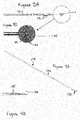
Figure 7A is a schematic representation of an electrode structure being implanted on a blood vessel with the use of an implant tool, according to an embodiment of the present invention. -
Figure 7B is a schematic representation of the electrode structure ofFigure 7A fixed in place on the blood vessel. -
Figures 8A and 8B are schematic representations of a baroreflex activation system according to an embodiment of the present invention implanted on a carotid sinus within a patient. -
Figure 9A is a plan view of the tissue contact side of an electrode structure according to an embodiment of the present invention. -
Figure 9B is a perspective view of a fixation member according to an embodiment of the present invention. -
Figures 10A-10E are perspective views of related electrode structure configurations according to embodiments of the present invention. -
Figure 11A is an isometric view of an electrode structure and fixation mechanism according to an embodiment of the present invention. -
Figure 11B is an elevation view of an implant tool according to another embodiment of the present invention for use with the electrode arrangement ofFigure 11A . -
Figure 11C is a close-up plan view of the electrode structure ofFigure 11A held in an open, retracted position by the implant tool ofFigure 11B . -
Figure 12A is a perspective view of an implant tool according to another embodiment of the present invention. -
Figure 12B is a perspective view of a fixation element for use with an electrode structure according to an embodiment of the present invention. -
Figure 13A is a table of operating parameters during an experiment described herein. -
Figure 13B is a graph depicting the results of the experiment described herein. -
Figure 14 is a schematic representation of a kit according to an embodiment of the present invention. - While the invention is amenable to various modifications and alternative forms, specifics thereof have been shown by way of example in the drawings and will be described in detail. It should be understood, however, that the intention is not to limit the invention to the particular embodiments described. On the contrary, the intention is to cover all modifications, equivalents, and alternatives falling within the spirit and scope of the invention.
- The following detailed description should be read with reference to the drawings in which similar elements in different drawings are numbered the same. The drawings, which are not necessarily to scale, depict illustrative embodiments and are not intended to limit the scope of the invention.
- To address the problems of hypertension, heart failure, other cardiovascular disorders and renal disorders, the present invention basically provides a number of devices, systems and methods by which the baroreflex system is activated to reduce excessive blood pressure, autonomic nervous system activity and neurohormonal activation. In particular, the present invention provides a number of devices, systems and methods by which baroreceptors may be activated, thereby indicating an increase in blood pressure and signaling the brain to reduce the body's blood pressure and level of sympathetic nervous system and neurohormonal activation, and increase parasympathetic nervous system activation, thus having a beneficial effect on the cardiovascular system and other body systems.
- For general information pertaining to the cardiovascular, circulatory and nervous systems, as well as baroreceptor and baroreflex therapy systems that may be used in whole or in part with embodiments of the present invention, reference is made to the following commonly assigned patent applications and patents:
U.S. Patent Application Ser. No. 10/284,063 , PublishedU.S. Patent Application Nos. 2005/0154418 to Kieval et al. ,2005/0251212 to Kieval et al. ,2006/0293712 to Kieval et al. ,2006/0004417 to Rossing et al. ,2006/0074453 to Kieval et al. ,2008/0082137 to Kieval et al. and2009/0143837 to Rossing et al. , andU.S. Patent Nos. 6,522,926 to Kieval et al. ,6,850,801 to Kieval et al. and6,985,774 to Kieval et al. , the disclosures of which are hereby incorporated by reference in their entireties except for the claims and any express definitions. - Refer now to
Figure 1 , which depicts a schematic illustration ofbaroreceptors 30 disposed in a genericvascular wall 40 and a schematic flow chart of thebaroreflex system 50.Baroreceptors 30 are profusely distributed within the vascular walls discussed previously, and generally form anarbor 32. Thebaroreceptor arbor 32 comprises a plurality ofbaroreceptors 30, each of which transmits baroreceptor signals to thebrain 52 vianerve 38. Thebaroreceptors 30 are so profusely distributed and arborized within thevascular wall 40 thatdiscrete baroreceptor arbors 32 are not readily discernable. To this end, those skilled in the art will appreciate that thebaroreceptors 30 depicted inFigure 1 are primarily schematic for purposes of illustration and discussion. - Baroreceptor signals in the arterial vasculature are used to activate a number of body systems which collectively may be referred to as the baroreflex system. For the purposes of the present invention, it will be assumed that the "receptors" in the venous and cardiopulmonary vasculature and heart chambers function analogously to the baroreceptors in the arterial vasculature, but such assumption is not intended to limit the present invention in any way. In particular, the methods described herein will function and achieve at least some of the stated therapeutic objectives regardless of the precise and actual mechanism responsible for the result. Moreover, the present invention may activate baroreceptors, mechanoreceptors, pressoreceptors, stretch receptors, chemoreceptors, or any other venous, heart, or cardiopulmonary receptors which affect the blood pressure, nervous system activity, and neurohormonal activity in a manner analogous to baroreceptors in the arterial vasculation. For convenience, all such venous receptors will be referred to collectively herein as "baroreceptors" or "receptors" unless otherwise expressly noted.
- While there may be small structural or anatomical differences among various receptors in the vasculature, for the purposes of some embodiments of the present invention, activation may be directed at any of these receptors and/or nerves and/or nerve endings from these receptors so long as they provide the desired effects. In particular, such receptors will provide afferent signals, i.e., signals to the brain, which provide the blood pressure and/or volume information to the brain. This allows the brain to cause "reflex" changes in the autonomic nervous system, which in turn modulate organ activity to maintain desired hemodynamics and organ perfusion. Stimulation of the baroreflex system may be accomplished by stimulating such receptors, nerves, nerve fibers, or nerve endings, or any combination thereof.
- A baroreflex activation therapy system utilizing an improved electrode and lead arrangement according to embodiments of the present invention generally include a control system, a baroreceptor activation device, a lead and a sensor (optional). Referring now to
Figure 2 , one embodiment of a system for baroreflex therapy is depicted, including acontrol system 60, abaroreflex activation device 70, and one or more sensor(s) 80. Thecontrol system 60 may include atherapy block 61 comprising aprocessor 63 and amemory 62.Control system 60 is enclosed within a housing, or can, and is communicably coupled tobaroreflex activation device 70 such as by way ofelectric control cable 72, or by wireless means such as radiofrequency or other forms of wireless communication.Cable 72 may include anoptional attachment tab 73, which may be used to suture or otherwise attachcable 72 to a patient in order to provide strain relief to the electrode-tissue interface.Control system 60 includes adriver 66 to provide the desired power mode for thebaroreceptor activation device 70. For example if thebaroreceptor activation device 70 utilizes electrical actuation, thedriver 66 may comprise a power amplifier, pulse generator or the like to selectively deliver electrical control signals, and thecable 72 may comprise electrical lead(s). - The electrical control signal generated by the
driver 66 may be continuous, periodic, episodic or a combination thereof, as dictated by an algorithm contained inmemory 62 of thecontrol system 60. Continuous control signals include a constant pulse, a constant train of pulses, a triggered pulse and a triggered train of pulses. Periodic control signals include each of the continuous control signals described above which have a designated start time and a designated duration. Episodic control signals include each of the continuous control signals described above which are triggered by an episode. - The
control system memory 62 may contain data related to the sensor signal, the therapy signal, and/or values and commands provided by theinput device 64. Thememory 62 may also include software containing one or more algorithms defining one or more functions or relationships between the therapy signal and the sensor signal. The algorithm may dictate activation or deactivation therapy signals depending on the sensor signal or a mathematical derivative thereof. The algorithm may dictate an activation or deactivation therapy signal when the sensor signal falls below a lower predetermined threshold value, rises above an upper predetermined threshold value or when the sensor signal indicates a specific physiologic event. Thememory 62 may also include software containing one or more algorithms for determining patient physiological parameters based on a measured parameter. - In one embodiment, the sensor(s) 80 senses and/or monitors a parameter, and generates a signal indicative of the parameter. The parameter may be related to cardiovascular function, and/or indicative of a need to modify the baroreflex system, and/or a physical parameter such as vascular impedance. The
control system 60 receives the sensor signal fromsensor 80 and transmits the therapy signal to thebaroreflex activation device 70 by way ofcontrol cable 72. Thesensor 80 may be combined and/or integrated withbaroreflex activation device 70, e.g., an electrode having sensing and therapy capabilities, orsensor 80 may be separate frombaroreflex activation device 70 and communicably coupled to controlsystem 60. - The
control system 60 generates a control signal (also referred to as a therapy signal), which activates, deactivates or otherwise modulates thebaroreflex activation device 70. In one embodiment, the therapy signal is in the range of about I to 10 volts, at a rate between 5Hz and 200Hz. Typically, activation of thedevice 70 results in activation of thebaroreceptors 30. Alternatively, deactivation or modulation of thebaroreflex activation device 70 may cause or modify activation of thebaroreceptors 30. Thebaroreflex activation device 70 may include a wide variety of devices which utilize electrical means, such as electrodes, to activatebaroreceptors 30. - The
control system 60 may operate as a closed loop utilizing feedback from thesensor 80, and optionally other sensors, such as heart rate sensors, which may be incorporated, or as an open loop utilizing reprogramming commands received byinput device 64. The closed loop operation of thecontrol system 60 preferably utilizes some feedback from the sensor(s), but may also operate in an open loop mode without feedback. In a closed loop embodiment,control system 60 generates a control signal as a function of the signal received fromsensor 80. Thus, in one embodiment whensensor 80 detects a parameter indicative of the need to modify the baroreflex system activity (e.g., excessive blood pressure), thecontrol system 60 generates a therapy signal to modulate (e.g., activate) thebaroreflex activation device 70 thereby inducing abaroreceptor 30 signal that is perceived by thebrain 52 to be apparent excessive blood pressure. When thesensor 80 detects a parameter indicative of normal body function (e.g., normal blood pressure), thecontrol system 60 generates a therapy signal to modulate (e.g., deactivate) thebaroreflex activation device 70. - Programming commands received by the
input device 64 may directly influence the therapy signal, the output activation parameters, or may alter the software and related algorithms contained inmemory 62. The treating physician and/or patient may provide commands to inputdevice 64. In one embodiment, adisplay 65 may be used to view the sensor signal, therapy signal and/or the software/data contained inmemory 62.Control system 60 may be implanted in whole or in part. - In one embodiment,
baroreceptor activation device 70 comprises anelectrode structure 110.Electrode structure 110 generally includes anelectrode 112 mounted on, integrated with, or otherwise coupled to abacker 114.Electrode 112 may comprise platinum iridium, and may include a surface treatment, such as iridium oxide or titanium nitride and/or can include steroid, anti-inflammatory, antibiotic and/or analgesic compounds, for example.Backer 114 may be constructed of Dacron-reinforced insulated silicone, or other suitable materials that are flexible, sturdy, electrically insulative and/or suitable for implantation in a body.Backer 114 and/orelectrode 112 may comprise circular structures, or other suitable arrangements without departing from the spirit of the invention. Forexample backer 114 may include one or more tabs or features configured for facilitating fixation to tissue. In one embodiment,electrode 112 may have a diameter of about 1mm, andbacker 114 may have a diameter of about 6mm. However, it is contemplated thatelectrode 112 may have a diameter within a range of about 0.25mm-3mm, whilebacker 114 may have a diameter within a range of about 1mm-10mm. In one embodiment the diameter ofbacker 114 is at least twice the diameter ofelectrode 112. -
Electrode 112 comprises a cathode, and in one embodiment the housing ofcontrol system 60 may comprise an anode. In another embodiment, an anode may be provided as part oflead 72. In another embodiment, an anode is provided on a second lead which is also coupled to controlsystem 60. In all embodiments the anode is preferably sufficiently larger than the cathode, for example ten times larger. In another embodiment the anode is fifty times larger than the cathode. Further, the anode and cathode are preferably positioned at a minimum distance away from one another, for example, the distance may be about twenty times the cathode diameter. In another embodiment, the distance between anode and cathode is at least fifty times the cathode diameter. - One or
more electrode structures 110 may be provided as part of a baroreflex activation therapy system according to the present invention. For example, afirst electrode structure 110 may be positioned at a first anatomical location, while asecond electrode structure 110 is positioned at a second anatomical location, such as for example at a left carotid sinus and a right carotid sinus. Or afirst electrode structure 110 may be positioned at a first anatomical location while a second electrode structure is positioned at a second anatomical location proximate the first anatomical location, such as for example positioning first and second electrode structures proximate one another on the left carotid sinus and/or carotid arteries. -
Electrode structure 110 may also include an interface means 120 configured for coupling with an implant tool, and one or more fixation means 122. Preferably interface means 120 is included on the inactive side ofelectrode structure 110. As described herein, interface means (or attachment interface) may comprise a t-bar, a socket, or other structure capable of being coupled to or grasped by an implant tool. Referring now toFigures 3A-4C ,electrode structure 110 includes an interface means 120 in the form of t-bar 130 which includes abar portion 132 raised above the inactive side ofelectrode structure 110. T-bar 130 is configured to interface with animplant tool 134, which generally includes abody portion 136 and aninterface tip 138.Body portion 136 oftool 134 may be generally rigid, or may include an internal wire or coil to allowtool 134 to be bent or curved and retain the curved shape.Body portion 136 may also include a telescoping or similar arrangement to provide adjustability of the overall length oftool 134.Interface tip 138 may similarly include a telescoping or similar arrangement, separate from that of the body portion. One or more pivot points may also be provided ontool 134, such as betweentip 138 andbody portion 136, or at any desired location alongbody 136.Tip portion 138 includes a cradle 139 configured to releasably couple to t-bar 130, while allowingtool 134 to pivot, rotate, and/or otherwise provide freedom of movement about t-bar 130 to facilitate movingelectrode structure 110 around the curved surface of an implant location such as the outer surface of ablood vessel 40, as part of a mapping and/or implant procedure. - In another embodiment depicted in
Figures 5A-7A , interface means 120 comprises asocket 150 disposed on the inactive side ofelectrode structure 110.Socket 150 is configured to interface with animplant tool 154, which generally includes abody portion 156 and aninterface tip 158.Body portion 156 oftool 154 may be generally rigid, or may include an internal coil or wire to allowtool 154 to be bent or curved and retain the curved shape.Body portion 156 may also include a telescoping or similar arrangement to provide adjustability of the overall length oftool 154.Interface tip 158 may similarly include a telescoping or similar arrangement, separate from that of the body portion. One or more pivot points may also be provided ontool 154, such as betweentip 158 andbody portion 156, or at any desired location alongbody 156.Tip portion 158 includes aball end 159 configured to releasably couple tosocket 150 ofelectrode structure 110. The ball-and-socket arrangement provides a wide range of motion about multiple axes betweenelectrode structure 110 andimplant tool 154 to facilitate movingelectrode structure 110 around the curved surface of an implant location such as the outer surface of ablood vessel 40, as part of a mapping and/or implant procedure. This articulated ball-and-socket joint preferably provides at least three degrees of freedom: pitch, yaw and roll. Further, the ball-and-socket joint preferably provides a range of motion of up to 150 degrees in at least two separate axes. - In order to implant
electrode structure 110, a surgeon first identifies and marks the desired implant location. Without limitation, one example of a suitable site for delivering baroreflex activation therapy is the carotid sinus. The general implant location may be obtained with the use of ultrasound, or other imaging techniques known and available. A small incision is made on the patient in the identified region. The length of the incision should be less than four inches long, preferably less than two inches. The size of the incision needed will be determined by the location of the implant and the specific patient, however theelectrode structure 110 and implant tool embodiments described herein allow for the use of a minimally invasive incision as compared to implant procedures for previous baroreflex activation devices. - Determining an optimal location to affix
electrode structure 110 is critical for effective therapy, and a mapping procedure is therefore undertaken.Electrode structure 110 is releasably coupled to the implant tool, and introduced into the incision untilelectrode structure 110 is in contact with the implant site, such as for example the carotid sinus. A stimulation signal is provided toelectrode structure 110, such as from an external pulse generator, and one or more patient responses to the signal is then measured. Using the implant tool,electrode structure 110 is moved around the contours of the carotid sinus to different positions, with additional stimulation signals delivered and patient responses measured at each position. When the surgeon has located an optimal site for implantation,electrode structure 110 is fixed at the site. The implant tool is then removed. - A path may be tunneled for
lead 72 from the electrode implant location to the implant location ofcontrol system 60 housing. This path may be tunneled either before or after the mapping procedure. Iflead 72 includes a strainrelief attachment tab 73, the tab is then sutured in place nearelectrode structure 110. The control system housing is then implanted subcutaneously as known in the art, and the lead is attached.Figures 8A-8B are schematic illustrations of the baroreflex activation system fully implanted. - Numerous fixation means and techniques are provided for securing
electrode structure 110 to an implant site, and may include passive or active fixation.Electrode structure 110 may be sutured directly to a blood vessel, andbacker 114 may optionally include one ormore apertures 123 as depicted inFigure 9A , to facilitate a path for sutures throughbacker 114. Preferably at least two sutures are utilized to insureelectrode structure 110 is secure and in sufficient electrical contact with the blood vessel. - Another embodiment of a fixation means 122 for
electrode structure 110, depicted inFigure 9B , is a U-Clip technique utilizing self-closing nitinol U-Clip components. U-clips 124 (such as those produced by Medtronic, Inc. of Minneapolis, MN) can be used to secureelectrode structure 110, and are placed in the same positions as sutures. A suture needle is brought through the tissue to the location of the U-clip (on the end). The surgeon cuts the suture thread at the end nearest the U-clip and the U-clip assumes the deployed position. In some embodiments, an "off the shelf' U-clip as described above may have to be modified to use the correct number of connection points and to be the correct size and shape (such as by making them circular) to matchbacker 114. - In a further embodiment depicted in
Figures 10A-10E , fixation ofelectrode structure 110 is accomplished in whole or in part with the use of adhesives.Backer 114 may include one or more features to facilitate application of an adhesive, such asapertures 182,troughs 184, and/ortabs 186.Backer 114 may further include aperforated polyester mesh 188 strategically exposed to provide additional surface area to mate with the adhesive. Suitable adhesives include known medical adhesives such as Cryolife bioglue, acrylic-based adhesives or photo-activated adhesives. Anti-inflammatory and/or anti-scarring agents may be used in conjunction with an adhesive. Further, adhesive fixation be used in combination with other fixation means described herein. - In another embodiment depicted in
Figures 11A-11C ,electrode structure 110 includes an integrated, selectively deployableactive fixation element 160 which generally includes aframe portion 162 and a plurality offixation barbs 164.Fixation element 160 is coupled toelectrode structure 110, and may be constructed of shape-memory alloy such as nitinol, or other suitable materials. Animplant tool 170 is provided for mapping and implant ofelectrode structure 110, and generally includes a body portion 171 having a grasping means 172 at a distal end and a control means 173 at a proximal end. Control means 173 may be manipulated by a surgeon to cause grasping means 172 to holdframe portion 162 in a retracted position whereinfixation barbs 164 are retracted, thereby allowing introduction ofelectrode structure 110 to the implant site. A mapping procedure as described above may be carried out, and upon finding a satisfactory implant location, control means 173 is manipulated to cause grasping means 172 to releaseframe 162 and movefixation element 160 to a deployed position, allowingbarbs 164 to penetrate into the adventitia of a blood vessel and securingelectrode structure 110. - In an alternate embodiment depicted in
Figures 12A-12B ,fixation element 160 is deployed via a rotational approach. A plurality ofbarbs 164 are included on aframe 162, which is coupled to anelectrode structure 110.Barbs 164 may be pre-formed to have a helix-like curvature. When retained byimplant tool 140,barbs 164 are withdrawn intoimplant tool 140 or otherwise held in a retracted position as to allow for introduction ofelectrode structure 110 to the implant site and for mapping. When desired,implant tool 140 is manipulated to cause grasping means to rotatably deployfixation element 162. - Referring now to operation of a baroreflex therapy system according to the present invention, as mentioned above the control signal generated by the
control system 60 may be continuous, periodic, episodic or a combination thereof, as dictated by an algorithm contained inmemory 62. The algorithm contained inmemory 62 defines a stimulus regimen which dictates the characteristics of the control signal as a function of time, and thus dictates the stimulation of baroreceptors as a function of time. Continuous control signals include a pulse, a train of pulses, a triggered pulse and a triggered train of pulses, all of which are generated continuously. - The output (power or energy) level of the
baroreceptor activation device 70 may be altered by changing the voltage, current and/or signal duration. The output signal of thebaroreceptor activation device 70 may be, for example, constant current or constant voltage. In electrical activation embodiments using a modulated signal, wherein the output signal comprises, for example, a series of pulses, several pulse characteristics may be changed individually or in combination to change the power or energy level of the output signal. Such pulse characteristics include, but are not limited to: pulse amplitude (PA), pulse frequency (PF), pulse width or duration (PW), pulse waveform (square, triangular, sinusoidal, etc.), pulse polarity (for bipolar electrodes) and pulse phase (monophasic, biphasic). - In electrical activation embodiments wherein the output signal comprises a pulse train, several other signal characteristics may be changed in addition to the pulse characteristics described above. The control or output signal may comprise a pulse train which generally includes a series of pulses occurring in bursts. Pulse train characteristics which may be changed include, but are not limited to: burst amplitude (equal to pulse amplitude if constant within burst packet), burst waveform (i.e., pulse amplitude variation within burst packet), burst frequency (BF), and burst width or duration (BW). The signal or a portion thereof (e.g., burst within the pulse train) may be triggered by any of the events discussed previously, or by a particular portion of the arterial pressure signal or the ECG signal (e.g., R-wave), or another physiologic timing indicator. If the signal or a portion thereof is triggered, the triggering event may be changed and/or the delay from the triggering event may be changed.
- Control signal characteristics for a baroreflex therapy system having a
monopolar electrode 110 according to the present invention differ from prior approaches, and provide greater stimulation efficacy with a lower power consumption. For example, suitable pulse widths for the present invention are in the range of about 15 microseconds to 500 microseconds, preferably in the range of 60-200 microseconds, and more preferably in the range of 100-150 microseconds. Suitable pulse amplitudes are in the range of about 0.4-20 milliamps, preferably in the range of 3-10 milliamps, and more preferably in the range of 5-7 milliamps. Suitable pulse frequencies are in the range of about 10-100Hz, preferably in the range of 25-80Hz, and more preferably in the range of 40-70Hz. - A number of human patients were implanted with baroreflex activation therapy systems according to the embodiments described herein. These patients had systolic blood pressures in excess of 140mmHg despite the usage of at least three anti-hypertensive medications. The results of their first five months being implanted with the system are presented in
Figures 13A-13B , which depict the average operating parameters for the system and the average resulting blood pressure reduction. These results illustrate that therapy delivered in accordance with the embodiments described herein resulted in a significant reduction in blood pressure of the patient. - Referring now to
Figure 14 , in one embodiment a baroreflex therapy system can be provided to a user in akit 200.Kit 200 may include acontrol system 60 in a housing, abaroreflex activation device 70 having at least oneelectrode structure 110 and coupled to the control system, an optional sensor, anoptional implant tool 202, and a set ofinstructions 210 recorded on a tangible medium for implanting, programming and/or operating the system.Kit 200 may be comprised of one or more hermetically sealed and sterilized packages.Instructions 210 may be provided as part ofkit 200, or indications may be provided linking a user to electricallyaccessible instructions 210.Instructions 210 may include instructions for implantingelectrode structure 110 and the baroreflex activation therapy system as described herein including the use of an implant tool and/or a mapping procedure, and/or for programming and/oroperating control system 60. - Various modifications to the embodiments of the inventions may be apparent to one of skill in the art upon reading this disclosure. For example, persons of ordinary skill in the relevant art will recognize that the various features described for the different embodiments of the inventions can be suitably combined, un-combined, and re-combined with other features, alone, or in different combinations, within the spirit of the invention. Likewise, the various features described above should all be regarded as example embodiments, rather than limitations to the scope or spirit of the inventions. Therefore, the above is not contemplated to limit the scope of the present inventions.
- Persons of ordinary skill in the relevant arts will recognize that the inventions may comprise fewer features than illustrated in any individual embodiment described above. The embodiments described herein are not meant to be an exhaustive presentation of the ways in which the various features of the inventions may be combined. Accordingly, the embodiments are not mutually exclusive combinations of features; rather, the inventions may comprise a combination of different individual features selected from different individual embodiments, as understood by persons of ordinary skill in the art.
- Any incorporation by reference of documents above is limited such that no subject matter is incorporated that is contrary to the explicit disclosure herein. Any incorporation by reference of documents above is further limited such that no claims included in the documents are incorporated by reference herein. Any incorporation by reference of documents above is yet further limited such that any definitions provided in the documents are not incorporated by reference herein unless expressly included herein.
- For purposes of interpreting the claims for the embodiments of the present inventions, it is expressly intended that the provisions of
Section 112, sixth paragraph of 35 U.S.C. are not to be invoked unless the specific terms "means for" or "step for" are recited in a claim. - The disclosure of this application also includes the following numbered clauses:
- 1. An implantable baroreflex activation system, comprising:
- a control system having an implantable housing;
- an electrical lead, coupleable to the control system; and
- an electrode structure proximate a distal end of the electrical lead, the electrode structure including a monopolar electrode, a backing material having an effective surface area larger than and proximal of the monopolar electrode, and a means for releasably and pivotably interfacing with an implant tool positioned proximal of the backing material, wherein the electrode is configured for implantation on an outer surface of a blood vessel and the control system is programmed to deliver a baroreflex therapy via the monopolar electrode to a baroreceptor within a wall of the blood vessel.
- 2. The system of
clause 1, wherein the electrode comprises a cathode and the housing comprises an anode. - 3. The system of
clause 1, wherein the electrode comprises a cathode and the lead includes an anode. - 4. The system of
clause 1, further comprising an implant tool configured to pivotably releasably couple with the electrode structure via the means for interfacing. - 5. The system of
clause 1, wherein the electrode structure further includes a fixation means. - 6. The system of
clause 1, wherein the backing material has a diameter at least twice a diameter of the electrode. - 7. The system of
clause 1, wherein the means for releasably and pivotably interfacing comprises pivotably interfacing about at least two axes. - 8. The system of
clause 1, wherein the means for releasably and pivotably interfacing includes a range of motion of about 150 degrees at the means for interfacing. - 9. The system of
clause 1, wherein the control system programmed to deliver a baroreflex therapy is programmed to deliver a baroreflex therapy having a pulse frequency between 40-70Hz, a pulse width between 100-150 microseconds, and a pulse amplitude between 5-7 milliamps. - 10. The system of
clause 1, further comprising a set of instructions recorded on a tangible medium for implanting the system, the instructions including:- creating an incision in a patient;
- releasably coupling the electrode structure to an implant tool;
- determining a suitable implant location;
- securing the electrode structure at the implant location;
- implanting the housing; and
- connecting the electrode structure to the control system with the electrical lead.
- 11. The system of
clause 10, wherein the instruction for determining a suitable implant location comprises:- positioning the electrode proximate a baroreceptor at a first location;
- delivering a stimulation signal through the electrode;
- measuring a patient response to the signal;
- repositioning the electrode proximate a baroreceptor at a second location;
- delivering a stimulation signal through the electrode;
- measuring a patient response to the signal;
- comparing the patient response at the first location to the patient response at the second location; and
- selecting the implant location based on the comparing.
- 12. The system of
clause 1, wherein the electrode structure is configured to be adhesively secured to the blood vessel, the system further comprising an adhesive.
Claims (14)
- An implantable electrode structure for use in a baroreflex activation system, the implantable electrode structure configured for fixation by adhesive to a blood vessel, the electrode structure comprising:a backer;an electrode mounted on the backer, the electrode being configured to be placed in contact with the blood vessel; anda mesh which is exposed to provide additional surface area to mate with an adhesive to fix the electrode structure to the blood vessel.
- The implantable electrode structure of claim 1, wherein the backer includes the mesh, and wherein the backer has apertures with edges at which the mesh is exposed.
- The implantable electrode structure of claim 1, wherein the mesh extends outwardly of the backer.
- The implantable electrode structure of claim 1, wherein the mesh extends outwardly of the backer and has a trough for adhesive.
- The implantable electrode structure of claim 1, wherein the mesh has tabs which extend outwardly of the backer.
- The implantable electrode structure of claim 1, wherein the backer has apertures and wherein the mesh is exposed through the apertures.
- The implantable electrode structure of claim 1, wherein the backer includes one of more of apertures, troughs and tabs to facilitate application of an adhesive.
- The implantable electrode structure of any preceding claim, wherein the mesh is perforated.
- The implantable electrode structure of any preceding claim, further comprising an adhesive for application to the mesh.
- The implantable electrode structure of claim 8, further comprising an anti-inflammatory and/or anti-scarring agent for use in conjunction with the adhesive.
- A method of providing an implantable electrode structure for use in a baroreflex activation system, the implantable electrode structure configured for fixation by adhesive to a blood vessel, the method comprising forming the implantable electrode structure by:providing a backer having a first side and a second side;mounting an electrode on the first side of the backer, the electrode being configured to be placed in contact with the blood vessel; andproviding a mesh to provide additional surface area to mate with an adhesive to fix the electrode structure to the blood vessel.
- The implantable electrode structure of claim 11, wherein providing the mesh comprises providing the mesh as a layer on the first side of the backer.
- The implantable electrode structure of claim 11, wherein providing the mesh comprises providing the mesh within the backer.
- The implantable electrode structure of claim 11, wherein providing the mesh comprises providing the mesh exposed around or through the first side of the backer.
Applications Claiming Priority (4)
| Application Number | Priority Date | Filing Date | Title |
|---|---|---|---|
| US40842110P | 2010-10-29 | 2010-10-29 | |
| US201161515015P | 2011-08-04 | 2011-08-04 | |
| PCT/US2011/058676 WO2012058692A2 (en) | 2010-10-29 | 2011-10-31 | Implant tool and improved electrode design for minimally invasive procedure |
| EP11837271.3A EP2632535B1 (en) | 2010-10-29 | 2011-10-31 | Implant tool and improved electrode design for minimally invasive procedure |
Related Parent Applications (1)
| Application Number | Title | Priority Date | Filing Date |
|---|---|---|---|
| EP11837271.3A Division EP2632535B1 (en) | 2010-10-29 | 2011-10-31 | Implant tool and improved electrode design for minimally invasive procedure |
Publications (3)
| Publication Number | Publication Date |
|---|---|
| EP3124074A2 true EP3124074A2 (en) | 2017-02-01 |
| EP3124074A3 EP3124074A3 (en) | 2017-05-10 |
| EP3124074B1 EP3124074B1 (en) | 2020-12-02 |
Family
ID=45994862
Family Applications (2)
| Application Number | Title | Priority Date | Filing Date |
|---|---|---|---|
| EP16184400.6A Active EP3124074B1 (en) | 2010-10-29 | 2011-10-31 | Improved electrode design for minimally invasive procedure |
| EP11837271.3A Active EP2632535B1 (en) | 2010-10-29 | 2011-10-31 | Implant tool and improved electrode design for minimally invasive procedure |
Family Applications After (1)
| Application Number | Title | Priority Date | Filing Date |
|---|---|---|---|
| EP11837271.3A Active EP2632535B1 (en) | 2010-10-29 | 2011-10-31 | Implant tool and improved electrode design for minimally invasive procedure |
Country Status (6)
| Country | Link |
|---|---|
| US (7) | US8437867B2 (en) |
| EP (2) | EP3124074B1 (en) |
| JP (1) | JP5972272B2 (en) |
| CN (1) | CN103298521B (en) |
| AU (1) | AU2011320117B2 (en) |
| WO (1) | WO2012058692A2 (en) |
Families Citing this family (45)
| Publication number | Priority date | Publication date | Assignee | Title |
|---|---|---|---|---|
| US8862243B2 (en) | 2005-07-25 | 2014-10-14 | Rainbow Medical Ltd. | Electrical stimulation of blood vessels |
| WO2008070189A2 (en) | 2006-12-06 | 2008-06-12 | The Cleveland Clinic Foundation | Method and system for treating acute heart failure by neuromodulation |
| US9005106B2 (en) | 2008-01-31 | 2015-04-14 | Enopace Biomedical Ltd | Intra-aortic electrical counterpulsation |
| US8538535B2 (en) | 2010-08-05 | 2013-09-17 | Rainbow Medical Ltd. | Enhancing perfusion by contraction |
| US9974944B2 (en) | 2010-07-29 | 2018-05-22 | Cameron Health, Inc. | Subcutaneous leads and methods of implant and explant |
| EP3124074B1 (en) | 2010-10-29 | 2020-12-02 | CVRx, Inc. | Improved electrode design for minimally invasive procedure |
| US9199082B1 (en) | 2011-07-27 | 2015-12-01 | Cvrx, Inc. | Devices and methods for improved placement of implantable medical devices |
| EP2872070B1 (en) | 2011-09-09 | 2018-02-07 | Enopace Biomedical Ltd. | Wireless endovascular stent-based electrodes |
| GB201209771D0 (en) | 2012-06-01 | 2012-07-18 | Bioinduction Ltd | Precision delivery of electrical therapy |
| CA2878588A1 (en) | 2012-07-30 | 2014-02-06 | Northwestern University | Radiofrequency probe for circumferential ablation of a hollow cavity |
| EP3010580A1 (en) * | 2013-06-18 | 2016-04-27 | Cardiac Pacemakers, Inc. | System and method for mapping baroreceptors |
| US9345877B2 (en) | 2013-08-05 | 2016-05-24 | Cvrx, Inc. | Adapter for connection to pulse generator |
| WO2015068167A2 (en) | 2013-11-06 | 2015-05-14 | Enopace Biomedical Ltd. | Wireless endovascular stent-based electrodes |
| US9839785B2 (en) | 2013-12-13 | 2017-12-12 | Cardiac Pacemakers, Inc. | Surgical instrument for implanting leads for baroreceptor stimulation therapy |
| US10029091B2 (en) | 2014-02-20 | 2018-07-24 | Cardiac Pacemakers, Inc. | Apparatus for baroreceptor stimulation therapy |
| AU2015264121B2 (en) | 2014-05-22 | 2020-05-28 | CARDIONOMIC, Inc. | Catheter and catheter system for electrical neuromodulation |
| CN106456010B (en) * | 2014-06-19 | 2020-03-13 | 心脏起搏器股份公司 | Baroreceptor mapping system |
| US10743960B2 (en) | 2014-09-04 | 2020-08-18 | AtaCor Medical, Inc. | Cardiac arrhythmia treatment devices and delivery |
| CA2959183C (en) * | 2014-09-04 | 2023-10-10 | AtaCor Medical, Inc. | Receptacle for pacemaker lead |
| US9636505B2 (en) | 2014-11-24 | 2017-05-02 | AtaCor Medical, Inc. | Cardiac pacing sensing and control |
| US10328268B2 (en) | 2014-09-04 | 2019-06-25 | AtaCor Medical, Inc. | Cardiac pacing |
| AU2015315658B2 (en) | 2014-09-08 | 2019-05-23 | CARDIONOMIC, Inc. | Catheter and electrode systems for electrical neuromodulation |
| AU2015315570B2 (en) | 2014-09-08 | 2020-05-14 | CARDIONOMIC, Inc. | Methods for electrical neuromodulation of the heart |
| US11097109B2 (en) | 2014-11-24 | 2021-08-24 | AtaCor Medical, Inc. | Cardiac pacing sensing and control |
| EP3610917A1 (en) | 2015-01-05 | 2020-02-19 | Cardionomic, Inc. | Cardiac modulation facilitation methods and systems |
| US10342611B2 (en) | 2015-04-29 | 2019-07-09 | Innoblative Designs, Inc. | Cavitary tissue ablation |
| US10617402B2 (en) | 2015-07-22 | 2020-04-14 | Cameron Health, Inc. | Minimally invasive method to implant a subcutaneous electrode |
| EP3367945B1 (en) | 2015-10-29 | 2020-02-26 | Innoblative Designs, Inc. | Screen sphere tissue ablation devices |
| WO2017136261A1 (en) | 2016-02-02 | 2017-08-10 | Innoblative Designs, Inc. | Cavitary tissue ablation system |
| WO2017151431A1 (en) | 2016-03-01 | 2017-09-08 | Innoblative Designs, Inc. | Resecting and coagulating tissue |
| AU2017229496B2 (en) | 2016-03-09 | 2022-03-31 | CARDIONOMIC, Inc. | Cardiac contractility neurostimulation systems and methods |
| WO2018075389A1 (en) | 2016-10-17 | 2018-04-26 | Innoblative Designs, Inc. | Treatment devices and methods |
| JP6875757B2 (en) | 2016-11-08 | 2021-05-26 | イノブレイティブ デザインズ, インコーポレイテッド | Electrosurgical tissue and vascular seal device |
| US10653513B2 (en) | 2017-02-21 | 2020-05-19 | Vascular Dynamics, Inc. | Baroreceptor testing prior to implantation methods and apparatus |
| EP3658053B1 (en) | 2017-07-26 | 2023-09-13 | Innoblative Designs, Inc. | Minimally invasive articulating assembly having ablation capabilities |
| EP3664703A4 (en) | 2017-09-13 | 2021-05-12 | Cardionomic, Inc. | Neurostimulation systems and methods for affecting cardiac contractility |
| WO2019053445A1 (en) * | 2017-09-14 | 2019-03-21 | Galvani Bioelectronics Limited | Neuromodulation of baroreceptor reflex |
| JP2021535776A (en) | 2018-08-13 | 2021-12-23 | カーディオノミック,インク. | Systems and methods that act on systole and / or relaxation |
| EP3837005B1 (en) * | 2018-08-15 | 2024-01-24 | CVRx, Inc. | Devices for percutaneous electrode implant |
| JP2022531658A (en) | 2019-05-06 | 2022-07-08 | カーディオノミック,インク. | Systems and methods for noise reduction of physiological signals during electrical neural regulation |
| WO2020243534A1 (en) | 2019-05-29 | 2020-12-03 | AtaCor Medical, Inc. | Implantable electrical leads and associated delivery systems |
| US11666771B2 (en) | 2020-05-29 | 2023-06-06 | AtaCor Medical, Inc. | Implantable electrical leads and associated delivery systems |
| US11400299B1 (en) | 2021-09-14 | 2022-08-02 | Rainbow Medical Ltd. | Flexible antenna for stimulator |
| US20230201580A1 (en) | 2021-12-29 | 2023-06-29 | Cvrx, Inc. | Devices and methods for baroreflex activation |
| US20230405329A1 (en) * | 2022-06-13 | 2023-12-21 | Barologics, Inc. | Patient treatment systems for sensing cardiac depolarization and/or stimulating the carotid sinus nerve, and associated devices and methods |
Citations (10)
| Publication number | Priority date | Publication date | Assignee | Title |
|---|---|---|---|---|
| US6522926B1 (en) | 2000-09-27 | 2003-02-18 | Cvrx, Inc. | Devices and methods for cardiovascular reflex control |
| US6850801B2 (en) | 2001-09-26 | 2005-02-01 | Cvrx, Inc. | Mapping methods for cardiovascular reflex control devices |
| US20050154418A1 (en) | 2003-10-22 | 2005-07-14 | Kieval Robert S. | Baroreflex activation for pain control, sedation and sleep |
| US20050251212A1 (en) | 2000-09-27 | 2005-11-10 | Cvrx, Inc. | Stimulus regimens for cardiovascular reflex control |
| US20060004417A1 (en) | 2004-06-30 | 2006-01-05 | Cvrx, Inc. | Baroreflex activation for arrhythmia treatment |
| US6985774B2 (en) | 2000-09-27 | 2006-01-10 | Cvrx, Inc. | Stimulus regimens for cardiovascular reflex control |
| US20060074453A1 (en) | 2004-10-04 | 2006-04-06 | Cvrx, Inc. | Baroreflex activation and cardiac resychronization for heart failure treatment |
| US20060293712A1 (en) | 2004-03-02 | 2006-12-28 | Cvrx, Inc. | External baroreflex activation |
| US20080082137A1 (en) | 2006-09-28 | 2008-04-03 | Cvrx, Inc. | Electrode array structures and methods of use for cardiovascular reflex control |
| US20090143837A1 (en) | 2007-12-04 | 2009-06-04 | Rossing Martin A | Method and system for implantable pressure transducer for regulating blood pressure |
Family Cites Families (39)
| Publication number | Priority date | Publication date | Assignee | Title |
|---|---|---|---|---|
| US4058128A (en) | 1976-08-26 | 1977-11-15 | Frank Howard A | Electrode |
| AR216293A1 (en) | 1976-12-02 | 1979-12-14 | Leon De Pedro F | SELF-FIXING TOOTH ELECTRODE AND A GRIPPER FOR ITS MANEUVERING |
| US4146037A (en) | 1977-12-12 | 1979-03-27 | Cardiac Pacemakers, Inc. | Cardiac pacer electrode and lead insertion tool |
| US4306560A (en) * | 1978-07-10 | 1981-12-22 | Cordis Corporation | Suture forming tool for securing an electrode to generally inaccessible body tissue |
| US4291707A (en) * | 1979-04-30 | 1981-09-29 | Mieczyslaw Mirowski | Implantable cardiac defibrillating electrode |
| US4404971A (en) | 1981-04-03 | 1983-09-20 | Leveen Harry H | Dual balloon catheter |
| US4602624A (en) * | 1984-10-11 | 1986-07-29 | Case Western Reserve University | Implantable cuff, method of manufacture, and method of installation |
| US4827932A (en) * | 1987-02-27 | 1989-05-09 | Intermedics Inc. | Implantable defibrillation electrodes |
| US4800879A (en) | 1987-07-09 | 1989-01-31 | Vladimir Golyakhovsky | Disposable vascular occluder |
| US4920979A (en) * | 1988-10-12 | 1990-05-01 | Huntington Medical Research Institute | Bidirectional helical electrode for nerve stimulation |
| US4972847A (en) * | 1989-11-02 | 1990-11-27 | Dutcher Robert G | Pacing lead and introducer therefor |
| US5154182A (en) | 1991-02-15 | 1992-10-13 | Siemens Pacesetter, Inc. | Drug or steroid releasing patch electrode for an implantable arrhythmia treatment system |
| US5354328A (en) * | 1993-01-19 | 1994-10-11 | Siemens Pacesetter, Inc. | Patch electrode for an implantable defibrillator |
| US5385579A (en) | 1993-03-30 | 1995-01-31 | Siemens Pacesetter, Inc. | Myocardial body implantable lead |
| US5464447A (en) * | 1994-01-28 | 1995-11-07 | Sony Corporation | Implantable defibrillator electrodes |
| US6375615B1 (en) | 1995-10-13 | 2002-04-23 | Transvascular, Inc. | Tissue penetrating catheters having integral imaging transducers and their methods of use |
| US5800389A (en) | 1996-02-09 | 1998-09-01 | Emx, Inc. | Biopsy device |
| US20020035378A1 (en) * | 2000-09-18 | 2002-03-21 | Cameron Health, Inc. | Subcutaneous electrode for transthoracic conduction with highly maneuverable insertion tool |
| US6602241B2 (en) | 2001-01-17 | 2003-08-05 | Transvascular, Inc. | Methods and apparatus for acute or chronic delivery of substances or apparatus to extravascular treatment sites |
| US6718212B2 (en) | 2001-10-12 | 2004-04-06 | Medtronic, Inc. | Implantable medical electrical lead with light-activated adhesive fixation |
| US6978176B2 (en) * | 2001-12-08 | 2005-12-20 | Lattouf Omar M | Treatment for patient with congestive heart failure |
| US8774913B2 (en) | 2002-04-08 | 2014-07-08 | Medtronic Ardian Luxembourg S.A.R.L. | Methods and apparatus for intravasculary-induced neuromodulation |
| AU2003223583A1 (en) | 2002-04-11 | 2003-10-27 | Transvascular, Inc. | Devices and methods for transluminal or transthoracic interstitial electrode placement |
| US20060111626A1 (en) * | 2003-03-27 | 2006-05-25 | Cvrx, Inc. | Electrode structures having anti-inflammatory properties and methods of use |
| EP1620164B1 (en) * | 2003-05-06 | 2007-04-11 | Enpath Medical, Inc. | Rotatable lead introducer |
| US20050080470A1 (en) | 2003-10-09 | 2005-04-14 | Randy Westlund | Intramyocardial lead implantation system and method |
| US8126560B2 (en) * | 2003-12-24 | 2012-02-28 | Cardiac Pacemakers, Inc. | Stimulation lead for stimulating the baroreceptors in the pulmonary artery |
| US7369901B1 (en) * | 2004-02-11 | 2008-05-06 | Pacesetter, Inc. | Myocardial lead and lead system |
| WO2007000020A1 (en) | 2005-06-29 | 2007-01-04 | Compumedics Limited | Sensor assembly with conductive bridge |
| EP1948299A4 (en) * | 2005-08-11 | 2009-05-27 | Odem Medical Ltd | Cardiac resynchronization therapy systems and methods |
| WO2007038336A2 (en) | 2005-09-23 | 2007-04-05 | Ellipse Technologies, Inc. | Method and apparatus for adjusting body lumens |
| WO2007075593A1 (en) * | 2005-12-20 | 2007-07-05 | The Cleveland Clinic Foundation | Apparatus and method for modulating the baroreflex system |
| US20080004673A1 (en) * | 2006-04-03 | 2008-01-03 | Cvrx, Inc. | Implantable extravascular electrostimulation system having a resilient cuff |
| US20080132966A1 (en) * | 2006-12-05 | 2008-06-05 | G&L Consulting, Llc | Stimulation of coronary artery baroreceptors |
| US20080161887A1 (en) * | 2006-12-28 | 2008-07-03 | Cvrx, Inc. | Noble metal electrodes with nanostructures |
| US7996092B2 (en) * | 2007-01-16 | 2011-08-09 | Ndi Medical, Inc. | Devices, systems, and methods employing a molded nerve cuff electrode |
| US8594809B2 (en) * | 2008-04-25 | 2013-11-26 | Medtronic, Inc. | Passive fixation medical electrical lead |
| EP2211978A1 (en) * | 2008-04-30 | 2010-08-04 | Medtronic, Inc. | Techniques for placing medical leads for electrical stimulation of nerve tissue |
| EP3124074B1 (en) | 2010-10-29 | 2020-12-02 | CVRx, Inc. | Improved electrode design for minimally invasive procedure |
-
2011
- 2011-10-31 EP EP16184400.6A patent/EP3124074B1/en active Active
- 2011-10-31 US US13/286,169 patent/US8437867B2/en active Active
- 2011-10-31 EP EP11837271.3A patent/EP2632535B1/en active Active
- 2011-10-31 JP JP2013536915A patent/JP5972272B2/en active Active
- 2011-10-31 AU AU2011320117A patent/AU2011320117B2/en active Active
- 2011-10-31 WO PCT/US2011/058676 patent/WO2012058692A2/en active Application Filing
- 2011-10-31 CN CN201180052646.9A patent/CN103298521B/en active Active
-
2012
- 2012-07-02 US US13/540,218 patent/US8788066B2/en active Active
-
2014
- 2014-06-30 US US14/319,770 patent/US9511218B2/en active Active
-
2016
- 2016-08-30 US US15/251,239 patent/US10350406B2/en active Active
-
2019
- 2019-06-12 US US16/438,644 patent/US11058869B2/en active Active
-
2021
- 2021-06-11 US US17/345,858 patent/US11819682B2/en active Active
-
2023
- 2023-10-12 US US18/485,678 patent/US20240033504A1/en active Pending
Patent Citations (10)
| Publication number | Priority date | Publication date | Assignee | Title |
|---|---|---|---|---|
| US6522926B1 (en) | 2000-09-27 | 2003-02-18 | Cvrx, Inc. | Devices and methods for cardiovascular reflex control |
| US20050251212A1 (en) | 2000-09-27 | 2005-11-10 | Cvrx, Inc. | Stimulus regimens for cardiovascular reflex control |
| US6985774B2 (en) | 2000-09-27 | 2006-01-10 | Cvrx, Inc. | Stimulus regimens for cardiovascular reflex control |
| US6850801B2 (en) | 2001-09-26 | 2005-02-01 | Cvrx, Inc. | Mapping methods for cardiovascular reflex control devices |
| US20050154418A1 (en) | 2003-10-22 | 2005-07-14 | Kieval Robert S. | Baroreflex activation for pain control, sedation and sleep |
| US20060293712A1 (en) | 2004-03-02 | 2006-12-28 | Cvrx, Inc. | External baroreflex activation |
| US20060004417A1 (en) | 2004-06-30 | 2006-01-05 | Cvrx, Inc. | Baroreflex activation for arrhythmia treatment |
| US20060074453A1 (en) | 2004-10-04 | 2006-04-06 | Cvrx, Inc. | Baroreflex activation and cardiac resychronization for heart failure treatment |
| US20080082137A1 (en) | 2006-09-28 | 2008-04-03 | Cvrx, Inc. | Electrode array structures and methods of use for cardiovascular reflex control |
| US20090143837A1 (en) | 2007-12-04 | 2009-06-04 | Rossing Martin A | Method and system for implantable pressure transducer for regulating blood pressure |
Also Published As
| Publication number | Publication date |
|---|---|
| US20210308447A1 (en) | 2021-10-07 |
| EP2632535A2 (en) | 2013-09-04 |
| WO2012058692A3 (en) | 2012-07-19 |
| US11058869B2 (en) | 2021-07-13 |
| US8788066B2 (en) | 2014-07-22 |
| AU2011320117A1 (en) | 2013-05-23 |
| US10350406B2 (en) | 2019-07-16 |
| EP2632535B1 (en) | 2016-08-17 |
| AU2011320117B2 (en) | 2016-03-03 |
| US8437867B2 (en) | 2013-05-07 |
| CN103298521B (en) | 2015-09-16 |
| JP5972272B2 (en) | 2016-08-17 |
| EP2632535A4 (en) | 2014-09-03 |
| US20170007826A1 (en) | 2017-01-12 |
| WO2012058692A2 (en) | 2012-05-03 |
| US20120109250A1 (en) | 2012-05-03 |
| US20120271389A1 (en) | 2012-10-25 |
| US11819682B2 (en) | 2023-11-21 |
| EP3124074B1 (en) | 2020-12-02 |
| JP2013541390A (en) | 2013-11-14 |
| US20200001074A1 (en) | 2020-01-02 |
| US20240033504A1 (en) | 2024-02-01 |
| US20150142011A1 (en) | 2015-05-21 |
| US9511218B2 (en) | 2016-12-06 |
| EP3124074A3 (en) | 2017-05-10 |
| CN103298521A (en) | 2013-09-11 |
Similar Documents
| Publication | Publication Date | Title |
|---|---|---|
| US11819682B2 (en) | Implant tool and improved electrode design for minimally invasive procedure | |
| US11458304B2 (en) | Adapter for connection to pulse generator | |
| EP1706177B1 (en) | Lead for stimulating the baroreceptors in the pulmonary artery | |
| US8473076B2 (en) | Lead for stimulating the baroreceptors in the pulmonary artery | |
| US8126560B2 (en) | Stimulation lead for stimulating the baroreceptors in the pulmonary artery | |
| US8712531B2 (en) | Automatic baroreflex modulation responsive to adverse event | |
| WO2005084389A2 (en) | External baroreflex activation | |
| JP2010505465A (en) | Electrode array structure for cardiovascular reflex control and method of use thereof | |
| US20080288017A1 (en) | External Baroreflex Activation | |
| EP3837005B1 (en) | Devices for percutaneous electrode implant | |
| IL299585A (en) | Devices and methods for baroreflex activation |
Legal Events
| Date | Code | Title | Description |
|---|---|---|---|
| PUAI | Public reference made under article 153(3) epc to a published international application that has entered the european phase |
Free format text: ORIGINAL CODE: 0009012 |
|
| STAA | Information on the status of an ep patent application or granted ep patent |
Free format text: STATUS: THE APPLICATION HAS BEEN PUBLISHED |
|
| AC | Divisional application: reference to earlier application |
Ref document number: 2632535 Country of ref document: EP Kind code of ref document: P |
|
| AK | Designated contracting states |
Kind code of ref document: A2 Designated state(s): AL AT BE BG CH CY CZ DE DK EE ES FI FR GB GR HR HU IE IS IT LI LT LU LV MC MK MT NL NO PL PT RO RS SE SI SK SM TR |
|
| PUAL | Search report despatched |
Free format text: ORIGINAL CODE: 0009013 |
|
| AK | Designated contracting states |
Kind code of ref document: A3 Designated state(s): AL AT BE BG CH CY CZ DE DK EE ES FI FR GB GR HR HU IE IS IT LI LT LU LV MC MK MT NL NO PL PT RO RS SE SI SK SM TR |
|
| RIC1 | Information provided on ipc code assigned before grant |
Ipc: A61N 1/36 20060101ALI20170405BHEP Ipc: A61N 1/372 20060101ALI20170405BHEP Ipc: A61N 1/05 20060101AFI20170405BHEP |
|
| STAA | Information on the status of an ep patent application or granted ep patent |
Free format text: STATUS: REQUEST FOR EXAMINATION WAS MADE |
|
| 17P | Request for examination filed |
Effective date: 20171110 |
|
| RBV | Designated contracting states (corrected) |
Designated state(s): AL AT BE BG CH CY CZ DE DK EE ES FI FR GB GR HR HU IE IS IT LI LT LU LV MC MK MT NL NO PL PT RO RS SE SI SK SM TR |
|
| STAA | Information on the status of an ep patent application or granted ep patent |
Free format text: STATUS: EXAMINATION IS IN PROGRESS |
|
| 17Q | First examination report despatched |
Effective date: 20190723 |
|
| GRAP | Despatch of communication of intention to grant a patent |
Free format text: ORIGINAL CODE: EPIDOSNIGR1 |
|
| STAA | Information on the status of an ep patent application or granted ep patent |
Free format text: STATUS: GRANT OF PATENT IS INTENDED |
|
| INTG | Intention to grant announced |
Effective date: 20200605 |
|
| GRAS | Grant fee paid |
Free format text: ORIGINAL CODE: EPIDOSNIGR3 |
|
| GRAA | (expected) grant |
Free format text: ORIGINAL CODE: 0009210 |
|
| STAA | Information on the status of an ep patent application or granted ep patent |
Free format text: STATUS: THE PATENT HAS BEEN GRANTED |
|
| AC | Divisional application: reference to earlier application |
Ref document number: 2632535 Country of ref document: EP Kind code of ref document: P |
|
| AK | Designated contracting states |
Kind code of ref document: B1 Designated state(s): AL AT BE BG CH CY CZ DE DK EE ES FI FR GB GR HR HU IE IS IT LI LT LU LV MC MK MT NL NO PL PT RO RS SE SI SK SM TR |
|
| REG | Reference to a national code |
Ref country code: GB Ref legal event code: FG4D |
|
| REG | Reference to a national code |
Ref country code: AT Ref legal event code: REF Ref document number: 1340229 Country of ref document: AT Kind code of ref document: T Effective date: 20201215 Ref country code: CH Ref legal event code: EP |
|
| REG | Reference to a national code |
Ref country code: DE Ref legal event code: R096 Ref document number: 602011069554 Country of ref document: DE |
|
| REG | Reference to a national code |
Ref country code: IE Ref legal event code: FG4D |
|
| REG | Reference to a national code |
Ref country code: NL Ref legal event code: FP |
|
| PG25 | Lapsed in a contracting state [announced via postgrant information from national office to epo] |
Ref country code: GR Free format text: LAPSE BECAUSE OF FAILURE TO SUBMIT A TRANSLATION OF THE DESCRIPTION OR TO PAY THE FEE WITHIN THE PRESCRIBED TIME-LIMIT Effective date: 20210303 Ref country code: FI Free format text: LAPSE BECAUSE OF FAILURE TO SUBMIT A TRANSLATION OF THE DESCRIPTION OR TO PAY THE FEE WITHIN THE PRESCRIBED TIME-LIMIT Effective date: 20201202 Ref country code: RS Free format text: LAPSE BECAUSE OF FAILURE TO SUBMIT A TRANSLATION OF THE DESCRIPTION OR TO PAY THE FEE WITHIN THE PRESCRIBED TIME-LIMIT Effective date: 20201202 Ref country code: NO Free format text: LAPSE BECAUSE OF FAILURE TO SUBMIT A TRANSLATION OF THE DESCRIPTION OR TO PAY THE FEE WITHIN THE PRESCRIBED TIME-LIMIT Effective date: 20210302 |
|
| REG | Reference to a national code |
Ref country code: AT Ref legal event code: MK05 Ref document number: 1340229 Country of ref document: AT Kind code of ref document: T Effective date: 20201202 |
|
| PG25 | Lapsed in a contracting state [announced via postgrant information from national office to epo] |
Ref country code: PL Free format text: LAPSE BECAUSE OF FAILURE TO SUBMIT A TRANSLATION OF THE DESCRIPTION OR TO PAY THE FEE WITHIN THE PRESCRIBED TIME-LIMIT Effective date: 20201202 Ref country code: SE Free format text: LAPSE BECAUSE OF FAILURE TO SUBMIT A TRANSLATION OF THE DESCRIPTION OR TO PAY THE FEE WITHIN THE PRESCRIBED TIME-LIMIT Effective date: 20201202 Ref country code: LV Free format text: LAPSE BECAUSE OF FAILURE TO SUBMIT A TRANSLATION OF THE DESCRIPTION OR TO PAY THE FEE WITHIN THE PRESCRIBED TIME-LIMIT Effective date: 20201202 Ref country code: BG Free format text: LAPSE BECAUSE OF FAILURE TO SUBMIT A TRANSLATION OF THE DESCRIPTION OR TO PAY THE FEE WITHIN THE PRESCRIBED TIME-LIMIT Effective date: 20210302 |
|
| PG25 | Lapsed in a contracting state [announced via postgrant information from national office to epo] |
Ref country code: HR Free format text: LAPSE BECAUSE OF FAILURE TO SUBMIT A TRANSLATION OF THE DESCRIPTION OR TO PAY THE FEE WITHIN THE PRESCRIBED TIME-LIMIT Effective date: 20201202 |
|
| REG | Reference to a national code |
Ref country code: LT Ref legal event code: MG9D |
|
| PG25 | Lapsed in a contracting state [announced via postgrant information from national office to epo] |
Ref country code: RO Free format text: LAPSE BECAUSE OF FAILURE TO SUBMIT A TRANSLATION OF THE DESCRIPTION OR TO PAY THE FEE WITHIN THE PRESCRIBED TIME-LIMIT Effective date: 20201202 Ref country code: SK Free format text: LAPSE BECAUSE OF FAILURE TO SUBMIT A TRANSLATION OF THE DESCRIPTION OR TO PAY THE FEE WITHIN THE PRESCRIBED TIME-LIMIT Effective date: 20201202 Ref country code: PT Free format text: LAPSE BECAUSE OF FAILURE TO SUBMIT A TRANSLATION OF THE DESCRIPTION OR TO PAY THE FEE WITHIN THE PRESCRIBED TIME-LIMIT Effective date: 20210405 Ref country code: EE Free format text: LAPSE BECAUSE OF FAILURE TO SUBMIT A TRANSLATION OF THE DESCRIPTION OR TO PAY THE FEE WITHIN THE PRESCRIBED TIME-LIMIT Effective date: 20201202 Ref country code: CZ Free format text: LAPSE BECAUSE OF FAILURE TO SUBMIT A TRANSLATION OF THE DESCRIPTION OR TO PAY THE FEE WITHIN THE PRESCRIBED TIME-LIMIT Effective date: 20201202 Ref country code: SM Free format text: LAPSE BECAUSE OF FAILURE TO SUBMIT A TRANSLATION OF THE DESCRIPTION OR TO PAY THE FEE WITHIN THE PRESCRIBED TIME-LIMIT Effective date: 20201202 Ref country code: LT Free format text: LAPSE BECAUSE OF FAILURE TO SUBMIT A TRANSLATION OF THE DESCRIPTION OR TO PAY THE FEE WITHIN THE PRESCRIBED TIME-LIMIT Effective date: 20201202 |
|
| PG25 | Lapsed in a contracting state [announced via postgrant information from national office to epo] |
Ref country code: AT Free format text: LAPSE BECAUSE OF FAILURE TO SUBMIT A TRANSLATION OF THE DESCRIPTION OR TO PAY THE FEE WITHIN THE PRESCRIBED TIME-LIMIT Effective date: 20201202 |
|
| REG | Reference to a national code |
Ref country code: DE Ref legal event code: R097 Ref document number: 602011069554 Country of ref document: DE |
|
| PG25 | Lapsed in a contracting state [announced via postgrant information from national office to epo] |
Ref country code: IS Free format text: LAPSE BECAUSE OF FAILURE TO SUBMIT A TRANSLATION OF THE DESCRIPTION OR TO PAY THE FEE WITHIN THE PRESCRIBED TIME-LIMIT Effective date: 20210402 |
|
| PLBE | No opposition filed within time limit |
Free format text: ORIGINAL CODE: 0009261 |
|
| STAA | Information on the status of an ep patent application or granted ep patent |
Free format text: STATUS: NO OPPOSITION FILED WITHIN TIME LIMIT |
|
| PG25 | Lapsed in a contracting state [announced via postgrant information from national office to epo] |
Ref country code: AL Free format text: LAPSE BECAUSE OF FAILURE TO SUBMIT A TRANSLATION OF THE DESCRIPTION OR TO PAY THE FEE WITHIN THE PRESCRIBED TIME-LIMIT Effective date: 20201202 Ref country code: IT Free format text: LAPSE BECAUSE OF FAILURE TO SUBMIT A TRANSLATION OF THE DESCRIPTION OR TO PAY THE FEE WITHIN THE PRESCRIBED TIME-LIMIT Effective date: 20201202 |
|
| 26N | No opposition filed |
Effective date: 20210903 |
|
| PG25 | Lapsed in a contracting state [announced via postgrant information from national office to epo] |
Ref country code: DK Free format text: LAPSE BECAUSE OF FAILURE TO SUBMIT A TRANSLATION OF THE DESCRIPTION OR TO PAY THE FEE WITHIN THE PRESCRIBED TIME-LIMIT Effective date: 20201202 Ref country code: ES Free format text: LAPSE BECAUSE OF FAILURE TO SUBMIT A TRANSLATION OF THE DESCRIPTION OR TO PAY THE FEE WITHIN THE PRESCRIBED TIME-LIMIT Effective date: 20201202 Ref country code: SI Free format text: LAPSE BECAUSE OF FAILURE TO SUBMIT A TRANSLATION OF THE DESCRIPTION OR TO PAY THE FEE WITHIN THE PRESCRIBED TIME-LIMIT Effective date: 20201202 |
|
| REG | Reference to a national code |
Ref country code: CH Ref legal event code: PL |
|
| PG25 | Lapsed in a contracting state [announced via postgrant information from national office to epo] |
Ref country code: IS Free format text: LAPSE BECAUSE OF FAILURE TO SUBMIT A TRANSLATION OF THE DESCRIPTION OR TO PAY THE FEE WITHIN THE PRESCRIBED TIME-LIMIT Effective date: 20210402 |
|
| REG | Reference to a national code |
Ref country code: BE Ref legal event code: MM Effective date: 20211031 |
|
| PG25 | Lapsed in a contracting state [announced via postgrant information from national office to epo] |
Ref country code: MC Free format text: LAPSE BECAUSE OF FAILURE TO SUBMIT A TRANSLATION OF THE DESCRIPTION OR TO PAY THE FEE WITHIN THE PRESCRIBED TIME-LIMIT Effective date: 20201202 |
|
| PG25 | Lapsed in a contracting state [announced via postgrant information from national office to epo] |
Ref country code: LU Free format text: LAPSE BECAUSE OF NON-PAYMENT OF DUE FEES Effective date: 20211031 Ref country code: BE Free format text: LAPSE BECAUSE OF NON-PAYMENT OF DUE FEES Effective date: 20211031 |
|
| PG25 | Lapsed in a contracting state [announced via postgrant information from national office to epo] |
Ref country code: LI Free format text: LAPSE BECAUSE OF NON-PAYMENT OF DUE FEES Effective date: 20211031 Ref country code: CH Free format text: LAPSE BECAUSE OF NON-PAYMENT OF DUE FEES Effective date: 20211031 |
|
| PG25 | Lapsed in a contracting state [announced via postgrant information from national office to epo] |
Ref country code: HU Free format text: LAPSE BECAUSE OF FAILURE TO SUBMIT A TRANSLATION OF THE DESCRIPTION OR TO PAY THE FEE WITHIN THE PRESCRIBED TIME-LIMIT; INVALID AB INITIO Effective date: 20111031 Ref country code: CY Free format text: LAPSE BECAUSE OF FAILURE TO SUBMIT A TRANSLATION OF THE DESCRIPTION OR TO PAY THE FEE WITHIN THE PRESCRIBED TIME-LIMIT Effective date: 20201202 |
|
| P01 | Opt-out of the competence of the unified patent court (upc) registered |
Effective date: 20230517 |
|
| PGFP | Annual fee paid to national office [announced via postgrant information from national office to epo] |
Ref country code: NL Payment date: 20230915 Year of fee payment: 13 Ref country code: IE Payment date: 20230912 Year of fee payment: 13 Ref country code: GB Payment date: 20230907 Year of fee payment: 13 |
|
| PGFP | Annual fee paid to national office [announced via postgrant information from national office to epo] |
Ref country code: FR Payment date: 20230911 Year of fee payment: 13 |
|
| PGFP | Annual fee paid to national office [announced via postgrant information from national office to epo] |
Ref country code: DE Payment date: 20230912 Year of fee payment: 13 |