EP3123950A1 - Surgical staple cartridge with outer edge compression features - Google Patents
Surgical staple cartridge with outer edge compression features Download PDFInfo
- Publication number
- EP3123950A1 EP3123950A1 EP16181469.4A EP16181469A EP3123950A1 EP 3123950 A1 EP3123950 A1 EP 3123950A1 EP 16181469 A EP16181469 A EP 16181469A EP 3123950 A1 EP3123950 A1 EP 3123950A1
- Authority
- EP
- European Patent Office
- Prior art keywords
- compressible
- anvil
- tissue
- end effector
- deck
- Prior art date
- Legal status (The legal status is an assumption and is not a legal conclusion. Google has not performed a legal analysis and makes no representation as to the accuracy of the status listed.)
- Granted
Links
- 230000006835 compression Effects 0.000 title claims description 10
- 238000007906 compression Methods 0.000 title claims description 10
- 239000012636 effector Substances 0.000 claims abstract description 121
- 238000010304 firing Methods 0.000 claims description 49
- 230000004044 response Effects 0.000 claims description 10
- 230000000694 effects Effects 0.000 claims description 6
- 239000013536 elastomeric material Substances 0.000 claims description 2
- 239000006263 elastomeric foam Substances 0.000 claims 1
- 238000000034 method Methods 0.000 description 21
- 239000010410 layer Substances 0.000 description 10
- 230000033001 locomotion Effects 0.000 description 8
- 238000013519 translation Methods 0.000 description 8
- 230000007246 mechanism Effects 0.000 description 7
- 238000012986 modification Methods 0.000 description 4
- 230000004048 modification Effects 0.000 description 4
- 210000000056 organ Anatomy 0.000 description 4
- 230000005855 radiation Effects 0.000 description 4
- 230000015572 biosynthetic process Effects 0.000 description 3
- 238000004140 cleaning Methods 0.000 description 3
- 230000014509 gene expression Effects 0.000 description 3
- 238000003780 insertion Methods 0.000 description 3
- 230000037431 insertion Effects 0.000 description 3
- 238000009434 installation Methods 0.000 description 3
- 230000005540 biological transmission Effects 0.000 description 2
- 235000013351 cheese Nutrition 0.000 description 2
- 239000006260 foam Substances 0.000 description 2
- 239000000463 material Substances 0.000 description 2
- 238000001356 surgical procedure Methods 0.000 description 2
- 210000000115 thoracic cavity Anatomy 0.000 description 2
- 210000003813 thumb Anatomy 0.000 description 2
- 238000011282 treatment Methods 0.000 description 2
- 241000894006 Bacteria Species 0.000 description 1
- IAYPIBMASNFSPL-UHFFFAOYSA-N Ethylene oxide Chemical compound C1CO1 IAYPIBMASNFSPL-UHFFFAOYSA-N 0.000 description 1
- 239000004775 Tyvek Substances 0.000 description 1
- 229920000690 Tyvek Polymers 0.000 description 1
- 210000001015 abdomen Anatomy 0.000 description 1
- 230000009471 action Effects 0.000 description 1
- 230000006978 adaptation Effects 0.000 description 1
- 239000000853 adhesive Substances 0.000 description 1
- 230000001070 adhesive effect Effects 0.000 description 1
- 238000013459 approach Methods 0.000 description 1
- 230000000740 bleeding effect Effects 0.000 description 1
- 210000004204 blood vessel Anatomy 0.000 description 1
- 210000001124 body fluid Anatomy 0.000 description 1
- 230000008878 coupling Effects 0.000 description 1
- 238000010168 coupling process Methods 0.000 description 1
- 238000005859 coupling reaction Methods 0.000 description 1
- 239000003814 drug Substances 0.000 description 1
- 229940079593 drug Drugs 0.000 description 1
- 238000002651 drug therapy Methods 0.000 description 1
- 229920001971 elastomer Polymers 0.000 description 1
- 239000000806 elastomer Substances 0.000 description 1
- 210000003811 finger Anatomy 0.000 description 1
- 210000001035 gastrointestinal tract Anatomy 0.000 description 1
- 238000001415 gene therapy Methods 0.000 description 1
- 208000014674 injury Diseases 0.000 description 1
- 238000002955 isolation Methods 0.000 description 1
- 210000004072 lung Anatomy 0.000 description 1
- 238000002324 minimally invasive surgery Methods 0.000 description 1
- 229920000642 polymer Polymers 0.000 description 1
- 230000002980 postoperative effect Effects 0.000 description 1
- 230000002265 prevention Effects 0.000 description 1
- 230000008569 process Effects 0.000 description 1
- 238000011084 recovery Methods 0.000 description 1
- 239000012858 resilient material Substances 0.000 description 1
- 230000035945 sensitivity Effects 0.000 description 1
- 239000002356 single layer Substances 0.000 description 1
- 230000001954 sterilising effect Effects 0.000 description 1
- 238000004659 sterilization and disinfection Methods 0.000 description 1
- 230000001360 synchronised effect Effects 0.000 description 1
- 230000001225 therapeutic effect Effects 0.000 description 1
- 230000008733 trauma Effects 0.000 description 1
- 238000002604 ultrasonography Methods 0.000 description 1
- 210000001835 viscera Anatomy 0.000 description 1
- 210000000707 wrist Anatomy 0.000 description 1
Images


Classifications
-
- A—HUMAN NECESSITIES
- A61—MEDICAL OR VETERINARY SCIENCE; HYGIENE
- A61B—DIAGNOSIS; SURGERY; IDENTIFICATION
- A61B17/00—Surgical instruments, devices or methods, e.g. tourniquets
- A61B17/10—Surgical instruments, devices or methods, e.g. tourniquets for applying or removing wound clamps, e.g. containing only one clamp or staple; Wound clamp magazines
- A61B17/105—Wound clamp magazines
-
- A—HUMAN NECESSITIES
- A61—MEDICAL OR VETERINARY SCIENCE; HYGIENE
- A61B—DIAGNOSIS; SURGERY; IDENTIFICATION
- A61B17/00—Surgical instruments, devices or methods, e.g. tourniquets
- A61B17/068—Surgical staplers, e.g. containing multiple staples or clamps
- A61B17/072—Surgical staplers, e.g. containing multiple staples or clamps for applying a row of staples in a single action, e.g. the staples being applied simultaneously
- A61B17/07207—Surgical staplers, e.g. containing multiple staples or clamps for applying a row of staples in a single action, e.g. the staples being applied simultaneously the staples being applied sequentially
-
- A—HUMAN NECESSITIES
- A61—MEDICAL OR VETERINARY SCIENCE; HYGIENE
- A61B—DIAGNOSIS; SURGERY; IDENTIFICATION
- A61B17/00—Surgical instruments, devices or methods, e.g. tourniquets
- A61B17/068—Surgical staplers, e.g. containing multiple staples or clamps
-
- A—HUMAN NECESSITIES
- A61—MEDICAL OR VETERINARY SCIENCE; HYGIENE
- A61B—DIAGNOSIS; SURGERY; IDENTIFICATION
- A61B17/00—Surgical instruments, devices or methods, e.g. tourniquets
- A61B2017/00831—Material properties
- A61B2017/00862—Material properties elastic or resilient
-
- A—HUMAN NECESSITIES
- A61—MEDICAL OR VETERINARY SCIENCE; HYGIENE
- A61B—DIAGNOSIS; SURGERY; IDENTIFICATION
- A61B17/00—Surgical instruments, devices or methods, e.g. tourniquets
- A61B17/068—Surgical staplers, e.g. containing multiple staples or clamps
- A61B17/072—Surgical staplers, e.g. containing multiple staples or clamps for applying a row of staples in a single action, e.g. the staples being applied simultaneously
- A61B2017/07214—Stapler heads
- A61B2017/07271—Stapler heads characterised by its cartridge
Definitions
- endoscopic surgical instruments may be preferred over traditional open surgical devices since a smaller incision may reduce the post-operative recovery time and complications. Consequently, some endoscopic surgical instruments may be suitable for placement of a distal end effector at a desired surgical site through the cannula of a trocar. These distal end effectors may engage tissue in a number of ways to achieve a diagnostic or therapeutic effect (e.g., endocutter, grasper, cutter, stapler, clip applier, access device, drug/gene therapy delivery device, and energy delivery device using ultrasonic vibration, RF, laser, etc.). Endoscopic surgical instruments may include a shaft between the end effector and a handle portion, which is manipulated by the clinician.
- Such a shaft may enable insertion to a desired depth and rotation about the longitudinal axis of the shaft, thereby facilitating positioning of the end effector within the patient. Positioning of an end effector may be further facilitated through inclusion of one or more articulation joints or features, enabling the end effector to be selectively articulated or otherwise deflected relative to the longitudinal axis of the shaft.
- endoscopic surgical instruments include surgical staplers. Some such staplers are operable to clamp down on layers of tissue, cut through the clamped layers of tissue, and drive staples through the layers of tissue to substantially seal the severed layers of tissue together near the severed ends of the tissue layers.
- surgical staplers are disclosed in U.S. Pat. No. 4,805,823 , entitled “Pocket Configuration for Internal Organ Staplers,” issued February 21, 1989; U.S. Pat. No. 5,415,334 , entitled “Surgical Stapler and Staple Cartridge,” issued May 16, 1995; U.S. Pat. No. 5,465,895 , entitled “Surgical Stapler Instrument,” issued November 14, 1995; U.S. Pat. No.
- surgical staplers referred to above are described as being used in endoscopic procedures, it should be understood that such surgical staplers may also be used in open procedures and/or other non-endoscopic procedures.
- a surgical stapler may be inserted through a thoracotomy, and thereby between a patient's ribs, to reach one or more organs in a thoracic surgical procedure that does not use a trocar as a conduit for the stapler.
- Such procedures may include the use of the stapler to sever and close a vessel leading to a lung. For instance, the vessels leading to an organ may be severed and closed by a stapler before removal of the organ from the thoracic cavity.
- surgical staplers may be used in various other settings and procedures.
- 2014/0239036 entitled “Jaw Closure Feature for End Effector of Surgical Instrument,” published August 28, 2014; U.S. Patent Pub. No. 2014/0239040 , entitled “Surgical Instrument with Articulation Lock having a Detenting Binary Spring,” published August 28, 2014; U.S. Patent Pub. No. 2014/0239043 , entitled “Distal Tip Features for End Effector of Surgical Instrument,” published August 28, 2014; U.S. Patent Pub. No. 2014/0239037 , entitled “Staple Forming Features for Surgical Stapling Instrument,” published August 28, 2014; U.S. Patent Pub. No. 2014/0239038 , entitled “Surgical Instrument with Multi-Diameter Shaft,” published August 28, 2014; and U.S. Patent Pub. No. 2014/0239044 , entitled “Installation Features for Surgical Instrument End Effector Cartridge,” published August 28, 2014.
- the present invention provides an apparatus as recited in the claims.
- FIG. 1 depicts an exemplary surgical stapling and severing instrument (10) that includes a handle assembly (20), a shaft assembly (30), and an end effector (40).
- End effector (40) and the distal portion of shaft assembly (30) are sized for insertion, in a nonarticulated state as depicted in FIG. 1 , through a trocar cannula to a surgical site in a patient for performing a surgical procedure.
- a trocar may be inserted in a patient's abdomen, between two of the patient's ribs, or elsewhere.
- instrument (10) is used without a trocar.
- end effector (40) and the distal portion of shaft assembly (30) may be inserted directly through a thoracotomy or other type of incision.
- terms such as “proximal” and “distal” are used herein with reference to a clinician gripping handle assembly (20) of instrument (10).
- end effector (40) is distal with respect to the more proximal handle assembly (20).
- spatial terms such as “vertical” and “horizontal” are used herein with respect to the drawings.
- surgical instruments are used in many orientations and positions, and these terms are not intended to be limiting and absolute.
- handle assembly (20) of the present example comprises pistol grip (22), a closure trigger (24), and a firing trigger (26). Each trigger (24, 26) is selectively pivotable toward and away from pistol grip (22) as will be described in greater detail below.
- Handle assembly (20) further includes an anvil release button (25), a firing beam reverse switch (27), and a removable battery pack (28). These components will also be described in greater detail below.
- handle assembly (20) may have a variety of other components, features, and operabilities, in addition to or in lieu of any of those noted above.
- Other suitable configurations for handle assembly (20) will be apparent to those of ordinary skill in the art in view of the teachings herein.
- shaft assembly (30) of the present example comprises an outer closure tube (32), an articulation section (34), and a closure ring (36), which is further coupled with end effector (40).
- Closure tube (32) extends along the length of shaft assembly (30).
- Closure ring (36) is positioned distal to articulation section (34).
- Closure tube (32) and closure ring (36) are configured to translate longitudinally relative to handle assembly (20). Longitudinal translation of closure tube (32) is communicated to closure ring (36) via articulation section (34). Exemplary features that may be used to provide longitudinal translation of closure tube (32) and closure ring (36) will be described in greater detail below.
- Articulation section (34) is operable to laterally deflect closure ring (36) and end effector (40) laterally away from the longitudinal axis (LA) of shaft assembly (30) at a desired angle ( ⁇ ). End effector (40) may thereby reach behind an organ or approach tissue from a desired angle or for other reasons.
- articulation section (34) enables deflection of end effector (40) along a single plane.
- articulation section (34) enables deflection of end effector along more than one plane.
- articulation is controlled through an articulation control knob (35) which is located at the proximal end of shaft assembly (30).
- Knob (35) is rotatable about an axis that is perpendicular to the longitudinal axis (LA) of shaft assembly (30).
- Closure ring (36) and end effector (40) pivot about an axis that is perpendicular to the longitudinal axis (LA) of shaft assembly (30) in response to rotation of knob (35).
- rotation of knob (35) clockwise may cause corresponding clockwise pivoting of closure ring (36) and end effector (40) at articulation section (34).
- Articulation section (34) is configured to communicate longitudinal translation of closure tube (32) to closure ring (36), regardless of whether articulation section (34) is in a straight configuration or an articulated configuration.
- articulation section (34) and/or articulation control knob (35) are/is constructed and operable in accordance with at least some of the teachings of U.S. Pub. No. 2014/0243801 , entitled “Surgical Instrument End Effector Articulation Drive with Pinion and Opposing Racks,” published August 28, 2014. Articulation section (34) may also be constructed and operable in accordance with at least some of the teachings of U.S. Pat. Pub. No. 2015/0374360 , entitled “Articulation Drive Features for Surgical Stapler,” filed June 25; and/or in accordance with the various teachings below.
- Other suitable forms that articulation section (34) and articulation knob (35) may take will be apparent to those of ordinary skill in the art in view of the teachings herein.
- shaft assembly (30) of the present example further includes a rotation knob (31).
- Rotation knob (31) is operable to rotate the entire shaft assembly (30) and end effector (40) relative to handle assembly (20) about the longitudinal axis (LA) of shaft assembly (30).
- rotation knob (31) is operable to selectively lock the angular position of shaft assembly (30) and end effector (40) relative to handle assembly (20) about the longitudinal axis (LA) of shaft assembly (30).
- rotation knob (31) may be translatable between a first longitudinal position, in which shaft assembly (30) and end effector (40) are rotatable relative to handle assembly (20) about the longitudinal axis (LA) of shaft assembly (30); and a second longitudinal position, in which shaft assembly (30) and end effector (40) are not rotatable relative to handle assembly (20) about the longitudinal axis (LA) of shaft assembly (30).
- shaft assembly (30) may have a variety of other components, features, and operabilities, in addition to or in lieu of any of those noted above.
- at least part of shaft assembly (30) is constructed in accordance with at least some of the teachings of U.S. Pub. No. 2014/0239038 , entitled "Surgical Instrument with Multi-Diameter Shaft,” published August 28, 2014 herein.
- Other suitable configurations for shaft assembly (30) will be apparent to those of ordinary skill in the art in view of the teachings herein.
- end effector (40) of the present example includes a lower jaw (50) and a pivotable anvil (60).
- Anvil (60) includes a pair of integral, outwardly extending pins (66) that are disposed in corresponding curved slots (54) of lower jaw (50). Pins (66) and slots (54) are shown in FIG. 5 .
- Anvil (60) is pivotable toward and away from lower jaw (50) between an open position (shown in FIGS. 2 and 4 ) and a closed position (shown in FIGS. 1 , 3 , and 7A-7B ).
- anvil (60) pivots about an axis that is defined by pins (66), which slide along curved slots (54) of lower jaw (50) as anvil (60) moves toward lower jaw (50).
- the pivot axis translates along the path defined by slots (54) while anvil (60) simultaneously pivots about that axis.
- the pivot axis may slide along slots (54) first, with anvil (60) then pivoting about the pivot axis after the pivot axis has slid a certain distance along the slots (54).
- pivotal movement is encompassed within terms such as “pivot,” “pivots,” “pivotal,” “pivotable,” “pivoting,” and the like.
- some versions may provide pivotal movement of anvil (60) about an axis that remains fixed and does not translate within a slot or channel, etc.
- lower jaw (50) of the present example defines a channel (52) that is configured to receive a staple cartridge (70).
- Staple cartridge (70) may be inserted into channel (52), end effector (40) may be actuated, and then staple cartridge (70) may be removed and replaced with another staple cartridge (70).
- Lower jaw (50) thus releasably retains staple cartridge (70) in alignment with anvil (60) for actuation of end effector (40).
- lower jaw (50) is constructed in accordance with at least some of the teachings of U.S. Pub. No. 2014/0239044 , entitled "Installation Features for Surgical Instrument End Effector Cartridge," published August 28, 2014. Other suitable forms that lower jaw (50) may take will be apparent to those of ordinary skill in the art in view of the teachings herein.
- staple cartridge (70) of the present example comprises a cartridge body (71) and a tray (76) secured to the underside of cartridge body (71).
- the upper side of cartridge body (71) presents a deck (73), against which tissue may be compressed when anvil (60) is in a closed position.
- Cartridge body (71) further defines a longitudinally extending channel (72) and a plurality of staple pockets (74).
- a staple (77) is positioned in each staple pocket (74).
- a staple driver (75) is also positioned in each staple pocket (74), underneath a corresponding staple (77), and above tray (76).
- staple drivers (75) are operable to translate upwardly in staple pockets (74) to thereby drive staples (77) upwardly through staple pockets (74) and into engagement with anvil (60).
- Staple drivers (75) are driven upwardly by a wedge sled (78), which is captured between cartridge body (71) and tray (76), and which translates longitudinally through cartridge body (71).
- Wedge sled (78) includes a pair of obliquely angled cam surfaces (79), which are configured to engage staple drivers (75) and thereby drive staple drivers (75) upwardly as wedge sled (78) translates longitudinally through cartridge (70). For instance, when wedge sled (78) is in a proximal position as shown in FIG.
- staple drivers (75) are in downward positions and staples (77) are located in staple pockets (74).
- wedge sled (78) As wedge sled (78) is driven to the distal position shown in FIG. 7B by a translating knife member (80), wedge sled (78) drives staple drivers (75) upwardly, thereby driving staples (77) out of staple pockets (74) and into staple forming pockets (64).
- staple drivers (75) translate along a vertical dimension as wedge sled (78) translates along a horizontal dimension.
- staple cartridge (70) may be varied in numerous ways.
- staple cartridge (70) of the present example includes two longitudinally extending rows of staple pockets (74) on one side of channel (72); and another set of two longitudinally extending rows of staple pockets (74) on the other side of channel (72).
- staple cartridge (70) includes three, one, or some other number of staple pockets (74) on each side of channel (72).
- staple cartridge (70) is constructed and operable in accordance with at least some of the teachings of U.S. Pub. No. 2014/0239042 , entitled "Integrated Tissue Positioning and Jaw Alignment Features for Surgical Stapler," published August 28,2014.
- staple cartridge (70) may be constructed and operable in accordance with at least some of the teachings of U.S. Pub. No. 2014/0239044 , entitled “Installation Features for Surgical Instrument End Effector Cartridge,” published August 28, 2014.
- Other suitable forms that staple cartridge (70) may take will be apparent to those of ordinary skill in the art in view of the teachings herein.
- anvil (60) of the present example comprises a longitudinally extending channel (62) and a plurality of staple forming pockets (64).
- Channel (62) is configured to align with channel (72) of staple cartridge (70) when anvil (60) is in a closed position.
- Each staple forming pocket (64) is positioned to lie over a corresponding staple pocket (74) of staple cartridge (70) when anvil (60) is in a closed position.
- Staple forming pockets (64) are configured to deform the legs of staples (77) when staples (77) are driven through tissue and into anvil (60).
- staple forming pockets (64) are configured to bend the legs of staples (77) to secure the formed staples (77) in the tissue.
- Anvil (60) may be constructed in accordance with at least some of the teachings of U.S. Pub. No. 2014/0239042 , entitled “Integrated Tissue Positioning and Jaw Alignment Features for Surgical Stapler,” published August 28, 2014; at least some of the teachings of U.S. Pub. No. 2014/0239036 , entitled “Jaw Closure Feature for End Effector of Surgical Instrument,” published August 28, 2014; and/or at least some of the teachings of U.S. Pub. No. 2014/0239037 , entitled “Staple Forming Features for Surgical Stapling Instrument,” published August 28, 2014.
- Other suitable forms that anvil (60) may take will be apparent to those of ordinary skill in the art in view of the teachings herein.
- a knife member (80) is configured to translate through end effector (40). As best seen in FIGS. 5 and 7A-7B , knife member (80) is secured to the distal end of a firing beam (82), which extends through a portion of shaft assembly (30). As best seen in FIGS. 4 and 6 , knife member (80) is positioned in channels (62, 72) of anvil (60) and staple cartridge (70). Knife member (80) includes a distally presented cutting edge (84) that is configured to sever tissue that is compressed between anvil (60) and deck (73) of staple cartridge (70) as knife member (80) translates distally through end effector (40). As noted above and as shown in FIGS.
- knife member (80) also drives wedge sled (78) distally as knife member (80) translates distally through end effector (40), thereby driving staples (77) through tissue and against anvil (60) into formation.
- wedge sled (78) distally as knife member (80) translates distally through end effector (40), thereby driving staples (77) through tissue and against anvil (60) into formation.
- end effector (40) includes lockout features that are configured to prevent knife member (80) from advancing distally through end effector (40) when a staple cartridge (70) is not inserted in lower jaw (50).
- end effector (40) may include lockout features that are configured to prevent knife member (80) from advancing distally through end effector (40) when a staple cartridge (70) that has already been actuated once (e.g., with all staples (77) deployed therefrom) is inserted in lower jaw (50).
- lockout features may be configured in accordance with at least some of the teachings of U.S. Pub. No.
- anvil (60) is driven toward lower jaw (50) by advancing closure ring (36) distally relative to end effector (40).
- Closure ring (36) cooperates with anvil (60) through a camming action to drive anvil (60) toward lower jaw (50) in response to distal translation of closure ring (36) relative to end effector (40).
- closure ring (36) may cooperate with anvil (60) to open anvil (60) away from lower jaw (50) in response to proximal translation of closure ring (36) relative to end effector (40).
- closure ring (36) and anvil (60) may interact in accordance with at least some of the teachings of U.S. Pub. No.
- handle assembly (20) includes a pistol grip (22) and a closure trigger (24).
- anvil (60) is closed toward lower jaw (50) in response to distal advancement of closure ring (36).
- closure trigger (24) is pivotable toward pistol grip (22) to drive closure tube (32) and closure ring (36) distally.
- suitable components that may be used to convert pivotal movement of closure trigger (24) toward pistol grip (22) into distal translation of closure tube (32) and closure ring (36) relative to handle assembly (20) will be apparent to those of ordinary skill in the art in view of the teachings herein.
- closure trigger (24) When closure trigger (24) reaches a fully pivoted state, such that anvil (60) is in a fully closed position relative to lower jaw (50), locking features in handle assembly (20) lock the position of trigger (24) and closure tube (32), thereby locking anvil (60) in a fully closed position relative to lower jaw (50). These locking features are released by actuation of anvil release button (25).
- Anvil release button (25) is configured and positioned to be actuated by the thumb of the operator hand that grasps pistol grip (22).
- the operator may grasp pistol grip (22) with one hand, actuate closure trigger (24) with one or more fingers of the same hand, and then actuate anvil release button (25) with the thumb of the same hand, without ever needing to release the grasp of pistol grip (22) with the same hand.
- closure trigger (24) with one or more fingers of the same hand
- anvil release button (25) with the thumb of the same hand
- Other suitable features that may be used to actuate anvil (60) will be apparent to those of ordinary skill in the art in view of the teachings herein.
- instrument (10) provides motorized control of firing beam (82).
- instrument (10) includes motorized components that are configured to drive firing beam (82) distally in response to pivoting of firing trigger (26) toward pistol grip (22).
- a motor (not shown) is contained in pistol grip (22) and receives power from battery pack (28). This motor is coupled with a transmission assembly (not shown) that converts rotary motion of a drive shaft of the motor into linear translation of firing beam (82).
- firing beam (82) may only be advanced distally when anvil (60) is in a fully closed position relative to lower jaw (50). After firing beam (82) is advanced distally to sever tissue and drive staples (77) as described above with reference to FIGS.
- the drive assembly for firing beam (82) may be automatically reversed to drive firing beam (82) proximally back to the retracted position (e.g., back from the position shown in FIG. 7B to the position shown in FIG. 7A ).
- the operator may actuate firing beam reverse switch (27), which may reverse the drive assembly for firing beam (82) in order to retract firing beam (82) to a proximal position.
- Handle assembly (20) of the present example further includes a bailout feature (21), which is operable to provide a mechanical bailout allowing the operator to manually retract firing beam (82) proximally (e.g., in the event of power loss while firing beam (82) is in a distal position, etc.).
- the features that are operable to provide motorized actuation of firing beam (82) may be configured and operable in accordance with at least some of the teachings of U.S. Pat. No. 8,210,411 , entitled “Motor-Driven Surgical Instrument,” issued July 3,2012.
- the features that are operable to provide motorized actuation of firing beam (82) may be configured and operable in accordance with at least some of the teachings of U.S. Pat. No. 8,453,914 , entitled “Motor-Driven Surgical Cutting Instrument with Electric Actuator Directional Control Assembly,” issued June 4, 2013.
- the features that are operable to provide motorized actuation of firing beam (82) may be configured and operable in accordance with at least some of the teachings of U.S. Patent Pub. No. 2015/0272575 , entitled “Surgical Instrument Comprising a Sensor System,” filed March 26, 2014.
- firing beam (82) may be manually actuated in accordance with at least some of the teachings of any other reference cited herein.
- FIG. 8 shows end effector (40) having been actuated through a single stroke through tissue (90).
- cutting edge (84) obscured in FIG. 8
- staple drivers (75) have driven two alternating rows of staples (77) through the tissue (90) on each side of the cut line produced by cutting edge (84).
- Staples (77) are all oriented substantially parallel to the cut line in this example, though it should be understood that staples (77) may be positioned at any suitable orientations.
- end effector (40) is withdrawn from the trocar after the first stroke is complete, the spent staple cartridge (70) is replaced with a new staple cartridge (70), and end effector (40) is then again inserted through the trocar to reach the stapling site for further cutting and stapling. This process may be repeated until the desired amount of cuts and staples (77) have been provided.
- Anvil (60) may need to be closed to facilitate insertion and withdrawal through the trocar; and anvil (60) may need to be opened to facilitate replacement of staple cartridge (70).
- cutting edge (84) may cut tissue substantially contemporaneously with staples (77) being driven through tissue during each actuation stroke.
- cutting edge (84) just slightly lags behind driving of staples (77), such that a staple (47) is driven through the tissue just before cutting edge (84) passes through the same region of tissue, though it should be understood that this order may be reversed or that cutting edge (84) may be directly synchronized with adjacent staples.
- FIG. 8 shows end effector (40) being actuated in two layers (92, 94) of tissue (90), it should be understood that end effector (40) may be actuated through a single layer of tissue (90) or more than two layers (92, 94) of tissue.
- FIG. 8 shows end effector (40) being actuated in two substantially flat, apposed planar layers (92, 94) of tissue, it should be understood that end effector (40) may also be actuated across a tubular structure such as a blood vessel, a section of the gastrointestinal tract, etc.
- FIG. 8 should therefore not be viewed as demonstrating any limitation on the contemplated uses for end effector (40).
- instrument (10) may be used will be apparent to those of ordinary skill in the art in view of the teachings herein.
- instrument (10) may be configured and operable in accordance with any of the various references cited herein. Additional exemplary modifications that may be provided for instrument (10) will be described in greater detail below. Various suitable ways in which the below teachings may be incorporated into instrument (10) will be apparent to those of ordinary skill in the art. Similarly, various suitable ways in which the below teachings may be combined with various teachings of the references cited herein will be apparent to those of ordinary skill in the art. It should also be understood that the below teachings are not limited to instrument (10) or devices taught in the references cited herein. The below teachings may be readily applied to various other kinds of instruments, including instruments that would not be classified as surgical staplers. Various other suitable devices and settings in which the below teachings may be applied will be apparent to those of ordinary skill in the art in view of the teachings herein.
- End effector (40) may be structured to provide a predefined gap separating the surface of cartridge deck (73) and the corresponding surface of anvil (60) when anvil (60) is in a closed position.
- cutting and stapling tissue may be challenging if the thickness of the target tissue differs from this predefined gap distance. For example, if the target tissue is significantly thicker than the gap, an operator may have trouble firing the instrument to effectively cut and staple the tissue. On the other hand, if the target tissue is thinner than the gap between the cartridge deck and the anvil, it may be difficult to maintain the position of the target tissue between anvil (60) and deck (73).
- knife member (80) advances against the tissue, the tissue may shift position within the jaws of the instrument, thereby making it challenging to effectively cut the target tissue.
- staples (77) are driven through regions of tissue before knife member (80) reaches the same regions of tissue, such that the legs of staples (77) are disposed in the tissue before that region of tissue is severed.
- knife member (80) may plow the tissue rather than cutting it cleanly, which may result in staples (77) tearing through the tissue through a cheese wire effect.
- end effector (40) that compress relatively thin tissue to thereby secure the tissue as knife member (80) is actuated.
- Such compression of tissue may prevent undesirable movement of tissue that might otherwise occur when the tissue is positioned between a closed anvil (60) and deck (73).
- the compression features are present on staple cartridge (70), anvil (60), or both, as discussed in further detail below. By holding target tissue in place during firing of knife member (80), such compression features will aid in an effective cutting and stapling of tissue, even where the target tissue is thinner than the predefined gap distance between anvil (60) and deck (73) when anvil (60) is in a closed position.
- FIGS. 9A-10C show an exemplary alternative end effector (140) that includes an anvil (60) and a lower jaw (50). Anvil (60) is omitted from FIGS. 9A-9B for clarity.
- Lower jaw (50) includes an exemplary alternative staple cartridge (170).
- End effector (140) may be readily incorporated into instrument (10) in place of end effector (40). Except as otherwise described below, end effector (140) is configured and operable just like end effector (40) described above. For instance, knife member (80) may be driven through end effector (140) just like knife member (80) being driven through end effector (40) as described above.
- Staple cartridge (170) of the present example includes a set of opposing compressible features (196a, 196b) along outer edges (172) of staple cartridge (170). As shown, compressible features (196a, 196b) extend along opposite outer edges (172) of cartridge (170). As discussed in further detail below, compressible features (196a, 196b) are configured to act as bumpers to urge tissue captured between anvil (60) and lower jaw (50) toward anvil (60). Compressible features (196a, 196b) are configured to aid in applying compressive force to the target tissue clamped between anvil (60) and lower jaw (50) to hold target tissue in place.
- At least a portion of the target tissue is thinner than the predefined gap distance between anvil (60) and deck (73) when anvil (60) is in a closed position.
- end effector (140) is suitable for use with a variety of tissue thicknesses, including tissue that is thicker than the predefined gap distance between anvil (60) and deck (73) when anvil (60) is in a closed position.
- each compressible feature (196a, 196b) is a single, elongate feature extending longitudinally and upwardly along a corresponding edge (172) of cartridge (170). Further, each compressible feature (196a, 196b) is shown to extend along a substantial portion of the length of cartridge (170). However, in alternative examples, one or both of compressible features (196a, 196b) may be a formed as plurality of discrete, spaced apart elements that are positioned along a corresponding edge (172) of cartridge (170). Furthermore, in some examples, one or both of compressible features (196a, 196)b may only extend along a portion or certain portions of channel (72). Suitable other configurations and positions for compressible features (196a, 196b) will be apparent to persons skilled in the art in view of the teachings herein.
- each compressible feature (196a, 196b) includes a generally triangular cross-sectional profile with a first side (198) facing away from end effector (140), a second side (200) facing the anvil (60) and the longitudinal axis of end effector (140), and a third side (202) facing cartridge deck (73).
- compressive features (196a, 196b) decrease the effective distance between the anvil (60) and cartridge (170), such that the distance between the highest point (and many other points) of compressible features (196a, 196b) and anvil (60) is less than the distance between cartridge deck (73) and anvil (60).
- each compressive feature (196a, 196b) includes an opening (204) that further contributes to the compressibility of compressive features (196a, 196b).
- openings (204) provide clearance for first and second sides (198, 200) to compress toward corresponding third sides (202).
- compressive features (196a, 196b) lack openings (204).
- compressible features (196a, 196b) are separate elements from cartridge deck (73) and are fixed to cartridge deck (73) at the third sides (202) by various suitable methods as will be apparent to persons skilled in the art in view of the teachings herein.
- compressible features (196a, 196b) may be overmolded onto the cartridge deck (73) or other parts of cartridge (170).
- each compressible feature (196a, 196b) is integral with cartridge (170).
- compressible features (196a, 196b) may be co-molded with cartridge deck (73) or other parts of cartridge (170).
- compressible features (196a, 196b) are configured to be rigid enough to maintain their positions and urge tissue toward anvil (60) when an operator grasps tissue between anvil (60) and lower jaw (50).
- compressible features (196a, 196b) are also configured to be compressible a sufficient amount such that when an operator grasps tissue (90) between lower jaw (50) and anvil (60), compressible features (196a, 196b) do not prevent anvil (60) from moving to the fully closed position relative to the lower jaw (50) (as, for example, shown in FIGS. 10B-10C ).
- Other suitable configurations of compressive features (196a, 196b) will be apparent to persons skilled in the art in view of the teachings herein.
- compressible features (196a, 196b) may comprise a polymer and/or an elastomer.
- compressible features (196a, 196b) may be formed of a resilient material, such that compressible features (196a, 196b) resiliently bias tissue (90) against anvil (60) when tissue (90) is captured between anvil (60) and deck (73).
- Suitable other materials that may be used to form compressible features (196a, 196b) will be apparent to persons skilled in the art in view of the teachings herein.
- compressible features (196a, 196b) are in the form of a foam.
- compressible features (196a, 196b) may comprise other suitable forms, as will be apparent to persons skilled in the art in view of the teachings herein. It should be understood that, due to the compressibility and/or other properties of compressible features (196a, 196b), compressible features (196a, 196b) will not cause any trauma to tissue (90) even when compressible features (196a, 196b) compress the tissue (90) against anvil (60).
- end effector (140) may clamp tissue (90) in the same manner as described above with respect to end effector (40).
- the layers (92, 94) of tissue (90) are positioned between anvil (60) and lower jaw (150).
- the thickness of the layers (92, 94) of tissue (90) along at least a portion of the tissue (90) is less than the predefined gap distance between anvil (60) and cartridge deck (73) when anvil (60) is in the closed position.
- compressible features (196a, 196b) apply a substantially vertical load to the tissue (90) that is coincident with the compressible features (196a, 196b), compressing corresponding regions of tissue (90) against anvil (60).
- compressible features (196a, 196b) are compressible when tissue (90) is received in end effector (140), the extent to which depends on the thickness of tissue (90).
- end effector 140
- a portion of each compressible member (196a, 196b) deflects outwardly away from the longitudinal axis of end effector (140) such that a portion of each compressible member (196a, 196b) is outboard of the cartridge (170).
- compressible features (196a, 196b) contact tissue (90) at regions oftissue (90) that are substantially aligned with the edges (172) of cartridge (170).
- knife member (80) severs tissue (90).
- knife member (80) drives wedge sled (78) distally as knife member (80) translates distally through end effector (140), thereby driving staples (77) through tissue (90) and against anvil (60) into formation, in the same manner described above with respect to end effector (40).
- compressible features (196a, 196b) prevent tissue (90) from substantially moving during the severing and stapling of tissue (90).
- compressible features (196a, 196b) keep the tissue (90) substantially taut across the width defined between compressible features (196a, 196b), thereby preventing movement of tissue (90) along lateral paths that are transverse to the longitudinal axis of end effector (140).
- compressible features (196a, 196b) prevent movement of tissue (90) along paths that are parallel to the longitudinal axis of end effector (140).
- compressible features (196a, 196b) may reduce stress that might otherwise be imposed on tissue (90), at the regions where legs of staples (77) are driven through tissue (90), as knife member (80) as driven through tissue.
- compressible features (196a, 196b), rather than staples (77) may serve the role of holding tissue (90) in place as knife member (80) cuts through the tissue (90).
- staples (77) may need to serve the role of holding tissue (90) in place as knife member (80) cuts through the tissue (90), which may cause the tissue (90) to tear at staples (77) through a cheese wire effect. Such tearing may compromise the fixation of staples (77) in the tissue (90), which may ultimately result in full or partial failure of a deployed line of staples (77).
- Compressible features (196a, 166b) may thus maintain greater structural integrity of tissue (90) after end effector (140) has been actuated on the tissue (90); and may thus provide a more reliable line of staples (77) in the tissue.
- compressible features (196a, 196b) are shown as being part of cartridge (170) in the present example, it should be understood that similar compressible features may be readily incorporated into anvil (60). In versions where anvil (60) includes integral compressible features like compressible features (196a, 196b), cartridge (170) may still include compressible features (196a, 196b). In some such versions, the compressible features of anvil (60) may be laterally offset from compressible features (196a, 196b) of cartridge (170). In some other versions where anvil (60) includes integral compressible features like compressible features (196a, 196b), cartridge (170) may simply lack compressible features (196a, 196b).
- end effector (140) may be used as a tissue grasper by selectively opening and closing anvil (60), even with thin tissue structures, without necessarily firing knife member (80).
- Other suitable ways in which compressible features (196a, 196b) may be varied and used will be apparent to those of ordinary skill in the art in view of the teachings herein.
- An apparatus comprising: (a) a body; (b) a shaft assembly extending distally from the body, wherein the shaft assembly defines a longitudinal axis; (c) an end effector, wherein the end effector comprises: (i) an anvil, and (ii) a lower jaw, wherein the anvil is pivotable toward the lower jaw to capture tissue between the anvil and the lower jaw; and (d) a staple cartridge coupled with the lower jaw, wherein the staple cartridge comprises: (i) a deck facing the anvil, (ii) a plurality of staples positioned in a plurality of staple openings formed through the deck, and (iii) at least one compressible feature extending toward the anvil, wherein the at least one compressible feature is positioned along an outer region of the deck, wherein the at least one compressible feature is configured to compress tissue against the anvil.
- Example 1 wherein the deck defines opposing outer edges extending parallel to the longitudinal axis, wherein the at least one compressible feature comprises a pair of compressible features, wherein each of the compressible features extends along a corresponding one of the outer edges.
- Example 2 wherein a portion of each of the compressible features is configured to deflect outwardly away from the longitudinal axis of end effector such that a portion of each of the compressible features is outboard of the deck, in response to the end effector grasping tissue.
- Example 7 wherein the at least one compressible feature is configured to compress tissue against the anvil as the firing bar severs the tissue.
- the at least one compressible feature is configured to resiliently urge tissue clamped between the anvil and lower jaw toward the anvil.
- Example 13 wherein the at least one compressible feature further defines a length, wherein the opening extends along the length of the compressible feature.
- a staple cartridge for use with an end effector of a surgical stapler comprising: (a) a cartridge body, wherein the cartridge body includes a cartridge deck, wherein the cartridge body further defines a plurality of staple openings passing through the cartridge deck, wherein the cartridge deck includes a first outermost edge and a second outermost edge, wherein the outermost edges extend longitudinally along a length of the cartridge deck, wherein the staple openings are positioned between the outermost edges; (b) a plurality of staples associated with the plurality of staple openings; (c) a first compressible bumper extending along the first outermost edge; and (d) a second compressible bumper extending along the second outermost edge; wherein the first and second compressible bumpers are configured to remain on the cartridge body after the staples are directed out of the staple openings.
- each of the compressible bumpers defines an opening extending along the length of the compressible bumpers, wherein the opening of each of the compressible bumpers is configured to provide clearance for compression of the compressible bumpers.
- a method of using a surgical instrument comprising: (a) an end effector, wherein the end effector comprises: (i) an anvil, (ii) a lower jaw, wherein the anvil is configured to move toward and away from the lower jaw, and (iii) a staple cartridge disposed in the lower jaw, wherein the staple cartridge comprises: (A) a plurality of staples, (B) a deck facing the anvil, wherein the staples are configured to pass through the deck, and (C) a pair of compressible features extending along outer edges of the deck; and (b) a firing member configured to advance through the end effector to drive the staple drivers toward the anvil, the method comprising: (a) positioning tissue between the anvil and the lower jaw; (b) moving the anvil toward the jaw to place the anvil a closed position, wherein moving the anvil toward the jaw causes the compressible features to compress the tissue against the anvil, wherein the compressible features compress in response to compressing the tissue against the anvil; and (c)
- Example 19 The method according to Example 19, wherein the anvil and the deck define a gap when the anvil is in the closed position, wherein the gap defines a gap distance, wherein the tissue positioned between the anvil and the lower jaw has a thickness, wherein the thickness is less than the gap distance.
- 2012/0199630 entitled “Robotically-Controlled Surgical Instrument with Force-Feedback Capabilities,” published August 9, 2012; U.S. Pub. No. 2012/0132450 , entitled “Shiftable Drive Interface for Robotically-Controlled Surgical Tool,” published May 31, 2012; U.S. Pub. No. 2012/0199633 , entitled “Surgical Stapling Instruments with Cam-Driven Staple Deployment Arrangements,” published August 9, 2012; U.S. Pub. No. 2012/0199631 , entitled “Robotically-Controlled Motorized Surgical End Effector System with Rotary Actuated Closure Systems Having Variable Actuation Speeds,” published August 9, 2012; U.S. Pub. No.
- 2012/0199632 entitled “Robotically-Controlled Surgical Instrument with Selectively Articulatable End Effector,” published August 9, 2012; U.S. Pub. No. 2012/0203247 , entitled “Robotically-Controlled Surgical End Effector System,” published August 9, 2012; U.S. Pub. No. 2012/0211546 , entitled “Drive Interface for Operably Coupling a Manipulatable Surgical Tool to a Robot,” published August 23,2012; U.S. Pub. No. 2012/0138660 , entitled “Robotically-Controlled Cable-Based Surgical End Effectors,” published June 7, 2012; and/or U.S. Pub. No. 2012/0205421 , entitled “Robotically-Controlled Surgical End Effector System with Rotary Actuated Closure Systems,” published August 16, 2012.
- Versions of the devices described above may be designed to be disposed of after a single use, or they can be designed to be used multiple times. Versions may, in either or both cases, be reconditioned for reuse after at least one use. Reconditioning may include any combination of the steps of disassembly of the device, followed by cleaning or replacement of particular pieces, and subsequent reassembly. In particular, some versions of the device may be disassembled, and any number of the particular pieces or parts of the device may be selectively replaced or removed in any combination. Upon cleaning and/or replacement of particular parts, some versions of the device may be reassembled for subsequent use either at a reconditioning facility, or by a user immediately prior to a procedure.
- reconditioning of a device may utilize a variety of techniques for disassembly, cleaning/replacement, and reassembly. Use of such techniques, and the resulting reconditioned device, are all within the scope of the present application.
- versions described herein may be sterilized before and/or after a procedure.
- the device is placed in a closed and sealed container, such as a plastic or TYVEK bag.
- the container and device may then be placed in a field of radiation that can penetrate the container, such as gamma radiation, x-rays, or high-energy electrons.
- the radiation may kill bacteria on the device and in the container.
- the sterilized device may then be stored in the sterile container for later use.
- a device may also be sterilized using any other technique known in the art, including but not limited to beta or gamma radiation, ethylene oxide, or steam.
Abstract
Description
- In some settings, endoscopic surgical instruments may be preferred over traditional open surgical devices since a smaller incision may reduce the post-operative recovery time and complications. Consequently, some endoscopic surgical instruments may be suitable for placement of a distal end effector at a desired surgical site through the cannula of a trocar. These distal end effectors may engage tissue in a number of ways to achieve a diagnostic or therapeutic effect (e.g., endocutter, grasper, cutter, stapler, clip applier, access device, drug/gene therapy delivery device, and energy delivery device using ultrasonic vibration, RF, laser, etc.). Endoscopic surgical instruments may include a shaft between the end effector and a handle portion, which is manipulated by the clinician. Such a shaft may enable insertion to a desired depth and rotation about the longitudinal axis of the shaft, thereby facilitating positioning of the end effector within the patient. Positioning of an end effector may be further facilitated through inclusion of one or more articulation joints or features, enabling the end effector to be selectively articulated or otherwise deflected relative to the longitudinal axis of the shaft.
- Examples of endoscopic surgical instruments include surgical staplers. Some such staplers are operable to clamp down on layers of tissue, cut through the clamped layers of tissue, and drive staples through the layers of tissue to substantially seal the severed layers of tissue together near the severed ends of the tissue layers. Merely exemplary surgical staplers are disclosed in
U.S. Pat. No. 4,805,823 , entitled "Pocket Configuration for Internal Organ Staplers," issued February 21, 1989;U.S. Pat. No. 5,415,334 , entitled "Surgical Stapler and Staple Cartridge," issued May 16, 1995;U.S. Pat. No. 5,465,895 , entitled "Surgical Stapler Instrument," issued November 14, 1995;U.S. Pat. No. 5,597,107 , entitled "Surgical Stapler Instrument," issued January 28, 1997;U.S. Pat. No. 5,632,432 , entitled "Surgical Instrument," issued May 27, 1997;U.S. Pat. No. 5,673,840 , entitled "Surgical Instrument," issued October 7, 1997;U.S. Pat. No. 5,704,534 , entitled "Articulation Assembly for Surgical Instruments," issued January 6, 1998;U.S. Pat. No. 5,814,055 , entitled "Surgical Clamping Mechanism," issued September 29,1998;U.S. Pat. No. 6,978,921 , entitled "Surgical Stapling Instrument Incorporating an E-Beam Firing Mechanism," issued December 27, 2005;U.S. Pat. No. 7,000,818 , entitled "Surgical Stapling Instrument Having Separate Distinct Closing and Firing Systems," issued February 21, 2006;U.S. Pat. No. 7,143,923 , entitled "Surgical Stapling Instrument Having a Firing Lockout for an Unclosed Anvil," issued December 5, 2006;U.S. Pat. No. 7,303,108 , entitled "Surgical Stapling Instrument Incorporating a Multi-Stroke Firing Mechanism with a Flexible Rack," issued December 4, 2007;U.S. Pat. No. 7,367,485 , entitled "Surgical Stapling Instrument Incorporating a Multistroke Firing Mechanism Having a Rotary Transmission," issued May 6, 2008;U.S. Pat. No. 7,380,695 , entitled "Surgical Stapling Instrument Having a Single Lockout Mechanism for Prevention of Firing," issued June 3, 2008;U.S. Pat. No. 7,380,696 , entitled "Articulating Surgical Stapling Instrument Incorporating a Two-Piece E-Beam Firing Mechanism," issued June 3, 2008;U.S. Pat. No. 7,404,508 , entitled "Surgical Stapling and Cutting Device," issued July 29, 2008;U.S. Pat. No. 7,434,715 , entitled "Surgical Stapling Instrument Having Multistroke Firing with Opening Lockout," issued October 14, 2008;U.S. Pat. No. 7,721,930 , entitled "Disposable Cartridge with Adhesive for Use with a Stapling Device," issued May 25, 2010;U.S. Pat. No. 8,408,439 , entitled "Surgical Stapling Instrument with An Articulatable End Effector," issued April 2, 2013; andU.S. Pat. No. 8,453,914 , entitled "Motor-Driven Surgical Cutting Instrument with Electric Actuator Directional Control Assembly," issued June 4, 2013. - While the surgical staplers referred to above are described as being used in endoscopic procedures, it should be understood that such surgical staplers may also be used in open procedures and/or other non-endoscopic procedures. By way of example only, a surgical stapler may be inserted through a thoracotomy, and thereby between a patient's ribs, to reach one or more organs in a thoracic surgical procedure that does not use a trocar as a conduit for the stapler. Such procedures may include the use of the stapler to sever and close a vessel leading to a lung. For instance, the vessels leading to an organ may be severed and closed by a stapler before removal of the organ from the thoracic cavity. Of course, surgical staplers may be used in various other settings and procedures.
- Examples of surgical staplers that may be particularly suited or use through a thoracotomy are disclosed in
U.S. Patent Pub. No. 2014/0243801 , entitled "Surgical Instrument End Effector Articulation Drive with Pinion and Opposing Racks," published August 28, 2014;U.S. Patent Pub. No. 2014/0239041 , entitled "Lockout Feature for Movable Cutting Member of Surgical Instrument," published August 28, 2014;U.S. Patent Pub. No. 2014/0239042 , entitled "Integrated Tissue Positioning and Jaw Alignment Features for Surgical Stapler," published August 28, 2014;U.S. Patent Pub. No. 2014/0239036 , entitled "Jaw Closure Feature for End Effector of Surgical Instrument," published August 28, 2014;U.S. Patent Pub. No. 2014/0239040 , entitled "Surgical Instrument with Articulation Lock having a Detenting Binary Spring," published August 28, 2014;U.S. Patent Pub. No. 2014/0239043 , entitled "Distal Tip Features for End Effector of Surgical Instrument," published August 28, 2014;U.S. Patent Pub. No. 2014/0239037 , entitled "Staple Forming Features for Surgical Stapling Instrument," published August 28, 2014;U.S. Patent Pub. No. 2014/0239038 , entitled "Surgical Instrument with Multi-Diameter Shaft," published August 28, 2014; andU.S. Patent Pub. No. 2014/0239044 , entitled "Installation Features for Surgical Instrument End Effector Cartridge," published August 28, 2014. - While various kinds of surgical stapling instruments and associated components have been made and used, it is believed that no one prior to the inventor(s) has made or used the invention described in the appended claims.
- The present invention provides an apparatus as recited in the claims.
- The accompanying drawings, which are incorporated in and constitute a part of this specification, illustrate embodiments of the invention, and, together with the general description of the invention given above, and the detailed description of the embodiments given below, serve to explain the principles of the present invention.
-
FIG. 1 depicts a perspective view of an exemplary articulating surgical stapling instrument; -
FIG. 2 depicts a side elevational view of the instrument ofFIG. 1 ; -
FIG. 3 depicts a perspective view of an end effector of the instrument ofFIG. 1 , with the end effector in a closed configuration; -
FIG. 4 depicts a perspective view of the end effector ofFIG. 3 , with the end effector in an open configuration; -
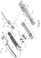
FIG. 5 depicts an exploded perspective view of the end effector ofFIG. 3 ; -
FIG. 6 depicts a cross-sectional end view of the end effector ofFIG. 3 , taken along line 6-6 ofFIG. 4 ; -
FIG. 7A depicts a cross-sectional side view of the end effector ofFIG. 3 , taken along line 7-7 ofFIG. 4 , with a firing beam in a proximal position; -
FIG. 7B depicts a cross-sectional side view of the end effector ofFIG. 3 , taken along line 7-7 ofFIG. 4 , with the firing beam in a distal position; -
FIG. 8 depicts a perspective view of the end effector ofFIG. 3 , positioned at tissue and having been actuated once in the tissue; -
FIG. 9A depicts a perspective view of an exemplary alternative end effector that may be incorporated into the instrument ofFIG. 1 , with a firing beam in a proximal position; -
FIG. 9B depicts a perspective view of the end effector ofFIG. 9A , with the firing beam in a distal position; -
FIG. 10A depicts a cross-sectional view of the end effector ofFIG. 9A , taken alongline 10A-10A ofFIG. 9A , with the firing beam in the proximal position; -
FIG. 10B depicts a cross-sectional view of the end effector ofFIG. 9A , taken alongline 10A-10A ofFIG. 9A , with the firing beam in the proximal position and tissue positioned between an anvil and staple cartridge deck of the end effector; and -
FIG. 10C depicts a cross-sectional view of the end effector ofFIG. 9A , taken alongline 10C-10C ofFIG. 9B , with the firing beam in a distal position and tissue positioned between the anvil and staple cartridge deck of the end effector. - The drawings are not intended to be limiting in any way, and it is contemplated that various embodiments of the invention may be carried out in a variety of other ways, including those not necessarily depicted in the drawings. The accompanying drawings incorporated in and forming a part of the specification illustrate several aspects of the present invention, and together with the description serve to explain the principles of the invention; it being understood, however, that this invention is not limited to the precise arrangements shown.
- The following description of certain examples of the invention should not be used to limit the scope of the present invention. Other examples, features, aspects, embodiments, and advantages of the invention will become apparent to those skilled in the art from the following description, which is by way of illustration, one of the best modes contemplated for carrying out the invention. As will be realized, the invention is capable of other different and obvious aspects, all without departing from the invention. Accordingly, the drawings and descriptions should be regarded as illustrative in nature and not restrictive.
-
FIG. 1 depicts an exemplary surgical stapling and severing instrument (10) that includes a handle assembly (20), a shaft assembly (30), and an end effector (40). End effector (40) and the distal portion of shaft assembly (30) are sized for insertion, in a nonarticulated state as depicted inFIG. 1 , through a trocar cannula to a surgical site in a patient for performing a surgical procedure. By way of example only, such a trocar may be inserted in a patient's abdomen, between two of the patient's ribs, or elsewhere. In some settings, instrument (10) is used without a trocar. For instance, end effector (40) and the distal portion of shaft assembly (30) may be inserted directly through a thoracotomy or other type of incision. It should be understood that terms such as "proximal" and "distal" are used herein with reference to a clinician gripping handle assembly (20) of instrument (10). Thus, end effector (40) is distal with respect to the more proximal handle assembly (20). It will be further appreciated that for convenience and clarity, spatial terms such as "vertical" and "horizontal" are used herein with respect to the drawings. However, surgical instruments are used in many orientations and positions, and these terms are not intended to be limiting and absolute. - As shown in
FIGS. 1-2 , handle assembly (20) of the present example comprises pistol grip (22), a closure trigger (24), and a firing trigger (26). Each trigger (24, 26) is selectively pivotable toward and away from pistol grip (22) as will be described in greater detail below. Handle assembly (20) further includes an anvil release button (25), a firing beam reverse switch (27), and a removable battery pack (28). These components will also be described in greater detail below. Of course, handle assembly (20) may have a variety of other components, features, and operabilities, in addition to or in lieu of any of those noted above. Other suitable configurations for handle assembly (20) will be apparent to those of ordinary skill in the art in view of the teachings herein. - As shown in
FIGS. 1-3 , shaft assembly (30) of the present example comprises an outer closure tube (32), an articulation section (34), and a closure ring (36), which is further coupled with end effector (40). Closure tube (32) extends along the length of shaft assembly (30). Closure ring (36) is positioned distal to articulation section (34). Closure tube (32) and closure ring (36) are configured to translate longitudinally relative to handle assembly (20). Longitudinal translation of closure tube (32) is communicated to closure ring (36) via articulation section (34). Exemplary features that may be used to provide longitudinal translation of closure tube (32) and closure ring (36) will be described in greater detail below. - Articulation section (34) is operable to laterally deflect closure ring (36) and end effector (40) laterally away from the longitudinal axis (LA) of shaft assembly (30) at a desired angle (α). End effector (40) may thereby reach behind an organ or approach tissue from a desired angle or for other reasons. In some versions, articulation section (34) enables deflection of end effector (40) along a single plane. In some other versions, articulation section (34) enables deflection of end effector along more than one plane. In the present example, articulation is controlled through an articulation control knob (35) which is located at the proximal end of shaft assembly (30). Knob (35) is rotatable about an axis that is perpendicular to the longitudinal axis (LA) of shaft assembly (30). Closure ring (36) and end effector (40) pivot about an axis that is perpendicular to the longitudinal axis (LA) of shaft assembly (30) in response to rotation of knob (35). By way of example only, rotation of knob (35) clockwise may cause corresponding clockwise pivoting of closure ring (36) and end effector (40) at articulation section (34). Articulation section (34) is configured to communicate longitudinal translation of closure tube (32) to closure ring (36), regardless of whether articulation section (34) is in a straight configuration or an articulated configuration.
- In some versions, articulation section (34) and/or articulation control knob (35) are/is constructed and operable in accordance with at least some of the teachings of
U.S. Pub. No. 2014/0243801 , entitled "Surgical Instrument End Effector Articulation Drive with Pinion and Opposing Racks," published August 28, 2014. Articulation section (34) may also be constructed and operable in accordance with at least some of the teachings ofU.S. Pat. Pub. No. 2015/0374360 , entitled "Articulation Drive Features for Surgical Stapler," filed June 25; and/or in accordance with the various teachings below. Other suitable forms that articulation section (34) and articulation knob (35) may take will be apparent to those of ordinary skill in the art in view of the teachings herein. - As shown in
FIGS. 1-2 , shaft assembly (30) of the present example further includes a rotation knob (31). Rotation knob (31) is operable to rotate the entire shaft assembly (30) and end effector (40) relative to handle assembly (20) about the longitudinal axis (LA) of shaft assembly (30). In some versions, rotation knob (31) is operable to selectively lock the angular position of shaft assembly (30) and end effector (40) relative to handle assembly (20) about the longitudinal axis (LA) of shaft assembly (30). For instance, rotation knob (31) may be translatable between a first longitudinal position, in which shaft assembly (30) and end effector (40) are rotatable relative to handle assembly (20) about the longitudinal axis (LA) of shaft assembly (30); and a second longitudinal position, in which shaft assembly (30) and end effector (40) are not rotatable relative to handle assembly (20) about the longitudinal axis (LA) of shaft assembly (30). Of course, shaft assembly (30) may have a variety of other components, features, and operabilities, in addition to or in lieu of any of those noted above. By way of example only, at least part of shaft assembly (30) is constructed in accordance with at least some of the teachings ofU.S. Pub. No. 2014/0239038 , entitled "Surgical Instrument with Multi-Diameter Shaft," published August 28, 2014 herein. Other suitable configurations for shaft assembly (30) will be apparent to those of ordinary skill in the art in view of the teachings herein. - As also shown in
FIGS. 1-3 , end effector (40) of the present example includes a lower jaw (50) and a pivotable anvil (60). Anvil (60) includes a pair of integral, outwardly extending pins (66) that are disposed in corresponding curved slots (54) of lower jaw (50). Pins (66) and slots (54) are shown inFIG. 5 . Anvil (60) is pivotable toward and away from lower jaw (50) between an open position (shown inFIGS. 2 and4 ) and a closed position (shown inFIGS. 1 ,3 , and7A-7B ). Use of the term "pivotable" (and similar terms with "pivot" as a base) should not be read as necessarily requiring pivotal movement about a fixed axis. For instance, in the present example, anvil (60) pivots about an axis that is defined by pins (66), which slide along curved slots (54) of lower jaw (50) as anvil (60) moves toward lower jaw (50). In such versions, the pivot axis translates along the path defined by slots (54) while anvil (60) simultaneously pivots about that axis. In addition or in the alternative, the pivot axis may slide along slots (54) first, with anvil (60) then pivoting about the pivot axis after the pivot axis has slid a certain distance along the slots (54). It should be understood that such sliding/translating pivotal movement is encompassed within terms such as "pivot," "pivots," "pivotal," "pivotable," "pivoting," and the like. Of course, some versions may provide pivotal movement of anvil (60) about an axis that remains fixed and does not translate within a slot or channel, etc. - As best seen in
FIG. 5 , lower jaw (50) of the present example defines a channel (52) that is configured to receive a staple cartridge (70). Staple cartridge (70) may be inserted into channel (52), end effector (40) may be actuated, and then staple cartridge (70) may be removed and replaced with another staple cartridge (70). Lower jaw (50) thus releasably retains staple cartridge (70) in alignment with anvil (60) for actuation of end effector (40). In some versions, lower jaw (50) is constructed in accordance with at least some of the teachings ofU.S. Pub. No. 2014/0239044 , entitled "Installation Features for Surgical Instrument End Effector Cartridge," published August 28, 2014. Other suitable forms that lower jaw (50) may take will be apparent to those of ordinary skill in the art in view of the teachings herein. - As best seen in
FIGS. 4-6 , staple cartridge (70) of the present example comprises a cartridge body (71) and a tray (76) secured to the underside of cartridge body (71). The upper side of cartridge body (71) presents a deck (73), against which tissue may be compressed when anvil (60) is in a closed position. Cartridge body (71) further defines a longitudinally extending channel (72) and a plurality of staple pockets (74). A staple (77) is positioned in each staple pocket (74). A staple driver (75) is also positioned in each staple pocket (74), underneath a corresponding staple (77), and above tray (76). As will be described in greater detail below, staple drivers (75) are operable to translate upwardly in staple pockets (74) to thereby drive staples (77) upwardly through staple pockets (74) and into engagement with anvil (60). Staple drivers (75) are driven upwardly by a wedge sled (78), which is captured between cartridge body (71) and tray (76), and which translates longitudinally through cartridge body (71). Wedge sled (78) includes a pair of obliquely angled cam surfaces (79), which are configured to engage staple drivers (75) and thereby drive staple drivers (75) upwardly as wedge sled (78) translates longitudinally through cartridge (70). For instance, when wedge sled (78) is in a proximal position as shown inFIG. 7A , staple drivers (75) are in downward positions and staples (77) are located in staple pockets (74). As wedge sled (78) is driven to the distal position shown inFIG. 7B by a translating knife member (80), wedge sled (78) drives staple drivers (75) upwardly, thereby driving staples (77) out of staple pockets (74) and into staple forming pockets (64). Thus, staple drivers (75) translate along a vertical dimension as wedge sled (78) translates along a horizontal dimension. - It should be understood that the configuration of staple cartridge (70) may be varied in numerous ways. For instance, staple cartridge (70) of the present example includes two longitudinally extending rows of staple pockets (74) on one side of channel (72); and another set of two longitudinally extending rows of staple pockets (74) on the other side of channel (72). However, in some other versions, staple cartridge (70) includes three, one, or some other number of staple pockets (74) on each side of channel (72). In some versions, staple cartridge (70) is constructed and operable in accordance with at least some of the teachings of
U.S. Pub. No. 2014/0239042 , entitled "Integrated Tissue Positioning and Jaw Alignment Features for Surgical Stapler," published August 28,2014. In addition or in the alternative, staple cartridge (70) may be constructed and operable in accordance with at least some of the teachings ofU.S. Pub. No. 2014/0239044 , entitled "Installation Features for Surgical Instrument End Effector Cartridge," published August 28, 2014. Other suitable forms that staple cartridge (70) may take will be apparent to those of ordinary skill in the art in view of the teachings herein. - As best seen in
FIG. 4 , anvil (60) of the present example comprises a longitudinally extending channel (62) and a plurality of staple forming pockets (64). Channel (62) is configured to align with channel (72) of staple cartridge (70) when anvil (60) is in a closed position. Each staple forming pocket (64) is positioned to lie over a corresponding staple pocket (74) of staple cartridge (70) when anvil (60) is in a closed position. Staple forming pockets (64) are configured to deform the legs of staples (77) when staples (77) are driven through tissue and into anvil (60). In particular, staple forming pockets (64) are configured to bend the legs of staples (77) to secure the formed staples (77) in the tissue. Anvil (60) may be constructed in accordance with at least some of the teachings ofU.S. Pub. No. 2014/0239042 , entitled "Integrated Tissue Positioning and Jaw Alignment Features for Surgical Stapler," published August 28, 2014; at least some of the teachings ofU.S. Pub. No. 2014/0239036 , entitled "Jaw Closure Feature for End Effector of Surgical Instrument," published August 28, 2014; and/or at least some of the teachings ofU.S. Pub. No. 2014/0239037 , entitled "Staple Forming Features for Surgical Stapling Instrument," published August 28, 2014. Other suitable forms that anvil (60) may take will be apparent to those of ordinary skill in the art in view of the teachings herein. - In the present example, a knife member (80) is configured to translate through end effector (40). As best seen in
FIGS. 5 and7A-7B , knife member (80) is secured to the distal end of a firing beam (82), which extends through a portion of shaft assembly (30). As best seen inFIGS. 4 and6 , knife member (80) is positioned in channels (62, 72) of anvil (60) and staple cartridge (70). Knife member (80) includes a distally presented cutting edge (84) that is configured to sever tissue that is compressed between anvil (60) and deck (73) of staple cartridge (70) as knife member (80) translates distally through end effector (40). As noted above and as shown inFIGS. 7A-7B , knife member (80) also drives wedge sled (78) distally as knife member (80) translates distally through end effector (40), thereby driving staples (77) through tissue and against anvil (60) into formation. Various features that may be used to drive knife member (80) distally through end effector (40) will be described in greater detail below. - In some versions, end effector (40) includes lockout features that are configured to prevent knife member (80) from advancing distally through end effector (40) when a staple cartridge (70) is not inserted in lower jaw (50). In addition or in the alternative, end effector (40) may include lockout features that are configured to prevent knife member (80) from advancing distally through end effector (40) when a staple cartridge (70) that has already been actuated once (e.g., with all staples (77) deployed therefrom) is inserted in lower jaw (50). By way of example only, such lockout features may be configured in accordance with at least some of the teachings of
U.S. Pub. No. 2014/0239041 , entitled "Lockout Feature for Movable Cutting Member of Surgical Instrument," published August 28, 2014; and/or at least some of the teachings ofU.S. Pat. Pub. No. 2015/0374373 , entitled "Method of Using Lockout Features for Surgical Staple cartridge," filed on June 25, 2014 herein. Other suitable forms that lockout features may take will be apparent to those of ordinary skill in the art in view of the teachings herein. Alternatively, end effector (40) may simply omit such lockout features. - In the present example, anvil (60) is driven toward lower jaw (50) by advancing closure ring (36) distally relative to end effector (40). Closure ring (36) cooperates with anvil (60) through a camming action to drive anvil (60) toward lower jaw (50) in response to distal translation of closure ring (36) relative to end effector (40). Similarly, closure ring (36) may cooperate with anvil (60) to open anvil (60) away from lower jaw (50) in response to proximal translation of closure ring (36) relative to end effector (40). By way of example only, closure ring (36) and anvil (60) may interact in accordance with at least some of the teachings of
U.S. Pub. No. 2014/0239036 , entitled "Jaw Closure Feature for End Effector of Surgical Instrument," published August 28, 2014; and/or in accordance with at least some of the teachings ofU.S. Patent Pub. No. 2015/0374373 , entitled "Jaw Opening Feature for Surgical Stapler," filed on June 25, 2014. Exemplary features that may be used to provide longitudinal translation of closure ring (36) relative to end effector (40) will be described in greater detail below. - As noted above, handle assembly (20) includes a pistol grip (22) and a closure trigger (24). As also noted above, anvil (60) is closed toward lower jaw (50) in response to distal advancement of closure ring (36). In the present example, closure trigger (24) is pivotable toward pistol grip (22) to drive closure tube (32) and closure ring (36) distally. Various suitable components that may be used to convert pivotal movement of closure trigger (24) toward pistol grip (22) into distal translation of closure tube (32) and closure ring (36) relative to handle assembly (20) will be apparent to those of ordinary skill in the art in view of the teachings herein. When closure trigger (24) reaches a fully pivoted state, such that anvil (60) is in a fully closed position relative to lower jaw (50), locking features in handle assembly (20) lock the position of trigger (24) and closure tube (32), thereby locking anvil (60) in a fully closed position relative to lower jaw (50). These locking features are released by actuation of anvil release button (25). Anvil release button (25) is configured and positioned to be actuated by the thumb of the operator hand that grasps pistol grip (22). In other words, the operator may grasp pistol grip (22) with one hand, actuate closure trigger (24) with one or more fingers of the same hand, and then actuate anvil release button (25) with the thumb of the same hand, without ever needing to release the grasp of pistol grip (22) with the same hand. Other suitable features that may be used to actuate anvil (60) will be apparent to those of ordinary skill in the art in view of the teachings herein.
- In the present example, instrument (10) provides motorized control of firing beam (82). In particular, instrument (10) includes motorized components that are configured to drive firing beam (82) distally in response to pivoting of firing trigger (26) toward pistol grip (22). In some versions, a motor (not shown) is contained in pistol grip (22) and receives power from battery pack (28). This motor is coupled with a transmission assembly (not shown) that converts rotary motion of a drive shaft of the motor into linear translation of firing beam (82). In some such versions, firing beam (82) may only be advanced distally when anvil (60) is in a fully closed position relative to lower jaw (50). After firing beam (82) is advanced distally to sever tissue and drive staples (77) as described above with reference to
FIGS. 7A-7B , the drive assembly for firing beam (82) may be automatically reversed to drive firing beam (82) proximally back to the retracted position (e.g., back from the position shown inFIG. 7B to the position shown inFIG. 7A ). Alternatively, the operator may actuate firing beam reverse switch (27), which may reverse the drive assembly for firing beam (82) in order to retract firing beam (82) to a proximal position. Handle assembly (20) of the present example further includes a bailout feature (21), which is operable to provide a mechanical bailout allowing the operator to manually retract firing beam (82) proximally (e.g., in the event of power loss while firing beam (82) is in a distal position, etc.). - By way of example only, the features that are operable to provide motorized actuation of firing beam (82) may be configured and operable in accordance with at least some of the teachings of
U.S. Pat. No. 8,210,411 , entitled "Motor-Driven Surgical Instrument," issued July 3,2012. As another merely illustrative example, the features that are operable to provide motorized actuation of firing beam (82) may be configured and operable in accordance with at least some of the teachings ofU.S. Pat. No. 8,453,914 , entitled "Motor-Driven Surgical Cutting Instrument with Electric Actuator Directional Control Assembly," issued June 4, 2013. As yet another merely illustrative example, the features that are operable to provide motorized actuation of firing beam (82) may be configured and operable in accordance with at least some of the teachings ofU.S. Patent Pub. No. 2015/0272575 , entitled "Surgical Instrument Comprising a Sensor System," filed March 26, 2014. - Other suitable components, features, and configurations that may be used to provide motorization of firing beam (82) will be apparent to those of ordinary skill in the art in view of the teachings herein. It should also be understood that some other versions may provide manual driving of firing beam (82), such that a motor may be omitted. By way of example only, firing beam (82) may be manually actuated in accordance with at least some of the teachings of any other reference cited herein.
-
FIG. 8 shows end effector (40) having been actuated through a single stroke through tissue (90). As shown, cutting edge (84) (obscured inFIG. 8 ) has cut through tissue (90), while staple drivers (75) have driven two alternating rows of staples (77) through the tissue (90) on each side of the cut line produced by cutting edge (84). Staples (77) are all oriented substantially parallel to the cut line in this example, though it should be understood that staples (77) may be positioned at any suitable orientations. In the present example, end effector (40) is withdrawn from the trocar after the first stroke is complete, the spent staple cartridge (70) is replaced with a new staple cartridge (70), and end effector (40) is then again inserted through the trocar to reach the stapling site for further cutting and stapling. This process may be repeated until the desired amount of cuts and staples (77) have been provided. Anvil (60) may need to be closed to facilitate insertion and withdrawal through the trocar; and anvil (60) may need to be opened to facilitate replacement of staple cartridge (70). - It should be understood that cutting edge (84) may cut tissue substantially contemporaneously with staples (77) being driven through tissue during each actuation stroke. In the present example, cutting edge (84) just slightly lags behind driving of staples (77), such that a staple (47) is driven through the tissue just before cutting edge (84) passes through the same region of tissue, though it should be understood that this order may be reversed or that cutting edge (84) may be directly synchronized with adjacent staples. While
FIG. 8 shows end effector (40) being actuated in two layers (92, 94) of tissue (90), it should be understood that end effector (40) may be actuated through a single layer of tissue (90) or more than two layers (92, 94) of tissue. It should also be understood that the formation and positioning of staples (77) adjacent to the cut line produced by cutting edge (84) may substantially seal the tissue at the cut line, thereby reducing or preventing bleeding and/or leaking of other bodily fluids at the cut line. Furthermore, whileFIG. 8 shows end effector (40) being actuated in two substantially flat, apposed planar layers (92, 94) of tissue, it should be understood that end effector (40) may also be actuated across a tubular structure such as a blood vessel, a section of the gastrointestinal tract, etc.FIG. 8 should therefore not be viewed as demonstrating any limitation on the contemplated uses for end effector (40). Various suitable settings and procedures in which instrument (10) may be used will be apparent to those of ordinary skill in the art in view of the teachings herein. - It should also be understood that any other components or features of instrument (10) may be configured and operable in accordance with any of the various references cited herein. Additional exemplary modifications that may be provided for instrument (10) will be described in greater detail below. Various suitable ways in which the below teachings may be incorporated into instrument (10) will be apparent to those of ordinary skill in the art. Similarly, various suitable ways in which the below teachings may be combined with various teachings of the references cited herein will be apparent to those of ordinary skill in the art. It should also be understood that the below teachings are not limited to instrument (10) or devices taught in the references cited herein. The below teachings may be readily applied to various other kinds of instruments, including instruments that would not be classified as surgical staplers. Various other suitable devices and settings in which the below teachings may be applied will be apparent to those of ordinary skill in the art in view of the teachings herein.
- End effector (40) may be structured to provide a predefined gap separating the surface of cartridge deck (73) and the corresponding surface of anvil (60) when anvil (60) is in a closed position. In some instances, cutting and stapling tissue may be challenging if the thickness of the target tissue differs from this predefined gap distance. For example, if the target tissue is significantly thicker than the gap, an operator may have trouble firing the instrument to effectively cut and staple the tissue. On the other hand, if the target tissue is thinner than the gap between the cartridge deck and the anvil, it may be difficult to maintain the position of the target tissue between anvil (60) and deck (73). Particularly, during firing, as knife member (80) advances against the tissue, the tissue may shift position within the jaws of the instrument, thereby making it challenging to effectively cut the target tissue. In some instances, staples (77) are driven through regions of tissue before knife member (80) reaches the same regions of tissue, such that the legs of staples (77) are disposed in the tissue before that region of tissue is severed. In such instances where the tissue is so thin that the tissue is not being held in place due to compression between anvil (60) and deck (73), knife member (80) may plow the tissue rather than cutting it cleanly, which may result in staples (77) tearing through the tissue through a cheese wire effect.
- In view of the foregoing, it may be desirable to provide one or more features in end effector (40) that compress relatively thin tissue to thereby secure the tissue as knife member (80) is actuated. Such compression of tissue may prevent undesirable movement of tissue that might otherwise occur when the tissue is positioned between a closed anvil (60) and deck (73). In some versions, the compression features are present on staple cartridge (70), anvil (60), or both, as discussed in further detail below. By holding target tissue in place during firing of knife member (80), such compression features will aid in an effective cutting and stapling of tissue, even where the target tissue is thinner than the predefined gap distance between anvil (60) and deck (73) when anvil (60) is in a closed position. Several examples of tissue compression features are described in greater detail below, while other examples will be apparent to those of ordinary skill in the art in view of the teachings herein.
-
FIGS. 9A-10C show an exemplary alternative end effector (140) that includes an anvil (60) and a lower jaw (50). Anvil (60) is omitted fromFIGS. 9A-9B for clarity. Lower jaw (50) includes an exemplary alternative staple cartridge (170). End effector (140) may be readily incorporated into instrument (10) in place of end effector (40). Except as otherwise described below, end effector (140) is configured and operable just like end effector (40) described above. For instance, knife member (80) may be driven through end effector (140) just like knife member (80) being driven through end effector (40) as described above. - Staple cartridge (170) of the present example includes a set of opposing compressible features (196a, 196b) along outer edges (172) of staple cartridge (170). As shown, compressible features (196a, 196b) extend along opposite outer edges (172) of cartridge (170). As discussed in further detail below, compressible features (196a, 196b) are configured to act as bumpers to urge tissue captured between anvil (60) and lower jaw (50) toward anvil (60). Compressible features (196a, 196b) are configured to aid in applying compressive force to the target tissue clamped between anvil (60) and lower jaw (50) to hold target tissue in place. In the example shown, at least a portion of the target tissue is thinner than the predefined gap distance between anvil (60) and deck (73) when anvil (60) is in a closed position. However, it will be understood that end effector (140) is suitable for use with a variety of tissue thicknesses, including tissue that is thicker than the predefined gap distance between anvil (60) and deck (73) when anvil (60) is in a closed position.
- As shown in the present example, each compressible feature (196a, 196b) is a single, elongate feature extending longitudinally and upwardly along a corresponding edge (172) of cartridge (170). Further, each compressible feature (196a, 196b) is shown to extend along a substantial portion of the length of cartridge (170). However, in alternative examples, one or both of compressible features (196a, 196b) may be a formed as plurality of discrete, spaced apart elements that are positioned along a corresponding edge (172) of cartridge (170). Furthermore, in some examples, one or both of compressible features (196a, 196)b may only extend along a portion or certain portions of channel (72). Suitable other configurations and positions for compressible features (196a, 196b) will be apparent to persons skilled in the art in view of the teachings herein.
- As best seen in
FIGS. 10A-10C , each compressible feature (196a, 196b) includes a generally triangular cross-sectional profile with a first side (198) facing away from end effector (140), a second side (200) facing the anvil (60) and the longitudinal axis of end effector (140), and a third side (202) facing cartridge deck (73). Thus, as shown in the present example, compressive features (196a, 196b) decrease the effective distance between the anvil (60) and cartridge (170), such that the distance between the highest point (and many other points) of compressible features (196a, 196b) and anvil (60) is less than the distance between cartridge deck (73) and anvil (60). As shown, each compressive feature (196a, 196b) includes an opening (204) that further contributes to the compressibility of compressive features (196a, 196b). In other words, openings (204) provide clearance for first and second sides (198, 200) to compress toward corresponding third sides (202). In some other examples, compressive features (196a, 196b) lack openings (204). - In the example shown, compressible features (196a, 196b) are separate elements from cartridge deck (73) and are fixed to cartridge deck (73) at the third sides (202) by various suitable methods as will be apparent to persons skilled in the art in view of the teachings herein. In some versions, compressible features (196a, 196b) may be overmolded onto the cartridge deck (73) or other parts of cartridge (170). In some versions, each compressible feature (196a, 196b) is integral with cartridge (170). In such some such versions, compressible features (196a, 196b) may be co-molded with cartridge deck (73) or other parts of cartridge (170). In the example shown, compressible features (196a, 196b) are configured to be rigid enough to maintain their positions and urge tissue toward anvil (60) when an operator grasps tissue between anvil (60) and lower jaw (50). However, compressible features (196a, 196b) are also configured to be compressible a sufficient amount such that when an operator grasps tissue (90) between lower jaw (50) and anvil (60), compressible features (196a, 196b) do not prevent anvil (60) from moving to the fully closed position relative to the lower jaw (50) (as, for example, shown in
FIGS. 10B-10C ). Other suitable configurations of compressive features (196a, 196b) will be apparent to persons skilled in the art in view of the teachings herein. - In some examples, compressible features (196a, 196b) may comprise a polymer and/or an elastomer. In addition or in the alternative, compressible features (196a, 196b) may be formed of a resilient material, such that compressible features (196a, 196b) resiliently bias tissue (90) against anvil (60) when tissue (90) is captured between anvil (60) and deck (73). Suitable other materials that may be used to form compressible features (196a, 196b) will be apparent to persons skilled in the art in view of the teachings herein. In the example shown, compressible features (196a, 196b) are in the form of a foam. Alternatively, compressible features (196a, 196b) may comprise other suitable forms, as will be apparent to persons skilled in the art in view of the teachings herein. It should be understood that, due to the compressibility and/or other properties of compressible features (196a, 196b), compressible features (196a, 196b) will not cause any trauma to tissue (90) even when compressible features (196a, 196b) compress the tissue (90) against anvil (60).
- Referring to
FIGS. 10B-10C , in use, end effector (140) may clamp tissue (90) in the same manner as described above with respect to end effector (40). As shown, the layers (92, 94) of tissue (90) are positioned between anvil (60) and lower jaw (150). In the example shown, the thickness of the layers (92, 94) of tissue (90) along at least a portion of the tissue (90) is less than the predefined gap distance between anvil (60) and cartridge deck (73) when anvil (60) is in the closed position. However, compressible features (196a, 196b) apply a substantially vertical load to the tissue (90) that is coincident with the compressible features (196a, 196b), compressing corresponding regions of tissue (90) against anvil (60). As shown, compressible features (196a, 196b) are compressible when tissue (90) is received in end effector (140), the extent to which depends on the thickness of tissue (90). When in the compressed condition as shown inFIGS. 10B-10C , a portion of each compressible member (196a, 196b) deflects outwardly away from the longitudinal axis of end effector (140) such that a portion of each compressible member (196a, 196b) is outboard of the cartridge (170). - In the example shown, compressible features (196a, 196b) contact tissue (90) at regions oftissue (90) that are substantially aligned with the edges (172) of cartridge (170). As shown in
FIG. 10C , as knife member (80) advances along channel (72), knife member (80) severs tissue (90). Moreover, knife member (80) drives wedge sled (78) distally as knife member (80) translates distally through end effector (140), thereby driving staples (77) through tissue (90) and against anvil (60) into formation, in the same manner described above with respect to end effector (40). As shown, compressible features (196a, 196b) prevent tissue (90) from substantially moving during the severing and stapling of tissue (90). In particular, by compressing tissue (90) against anvil (60), compressible features (196a, 196b) keep the tissue (90) substantially taut across the width defined between compressible features (196a, 196b), thereby preventing movement of tissue (90) along lateral paths that are transverse to the longitudinal axis of end effector (140). Moreover, compressible features (196a, 196b) prevent movement of tissue (90) along paths that are parallel to the longitudinal axis of end effector (140). - By firmly holding the position of tissue (90) between anvil (60) and cartridge deck (73), compressible features (196a, 196b) may reduce stress that might otherwise be imposed on tissue (90), at the regions where legs of staples (77) are driven through tissue (90), as knife member (80) as driven through tissue. In other words, compressible features (196a, 196b), rather than staples (77), may serve the role of holding tissue (90) in place as knife member (80) cuts through the tissue (90). In the absence of compressible features (196a, 196b), when tissue (90) is thinner than the predefined gap separating the surface of cartridge deck (73) and the corresponding surface of anvil (60) when anvil (60) is in a closed position, staples (77) may need to serve the role of holding tissue (90) in place as knife member (80) cuts through the tissue (90), which may cause the tissue (90) to tear at staples (77) through a cheese wire effect. Such tearing may compromise the fixation of staples (77) in the tissue (90), which may ultimately result in full or partial failure of a deployed line of staples (77). Compressible features (196a, 166b) may thus maintain greater structural integrity of tissue (90) after end effector (140) has been actuated on the tissue (90); and may thus provide a more reliable line of staples (77) in the tissue.
- While compressible features (196a, 196b) are shown as being part of cartridge (170) in the present example, it should be understood that similar compressible features may be readily incorporated into anvil (60). In versions where anvil (60) includes integral compressible features like compressible features (196a, 196b), cartridge (170) may still include compressible features (196a, 196b). In some such versions, the compressible features of anvil (60) may be laterally offset from compressible features (196a, 196b) of cartridge (170). In some other versions where anvil (60) includes integral compressible features like compressible features (196a, 196b), cartridge (170) may simply lack compressible features (196a, 196b). It should also be understood that, regardless of whether the compressible features are on anvil (60) and/or on cartridge (170), end effector (140) may be used as a tissue grasper by selectively opening and closing anvil (60), even with thin tissue structures, without necessarily firing knife member (80). Other suitable ways in which compressible features (196a, 196b) may be varied and used will be apparent to those of ordinary skill in the art in view of the teachings herein.
- The following examples relate to various non-exhaustive ways in which the teachings herein may be combined or applied. It should be understood that the following examples are not intended to restrict the coverage of any claims that may be presented at any time in this application or in subsequent filings of this application. No disclaimer is intended. The following examples are being provided for nothing more than merely illustrative purposes. It is contemplated that the various teachings herein may be arranged and applied in numerous other ways. It is also contemplated that some variations may omit certain features referred to in the below examples. Therefore, none of the aspects or features referred to below should be deemed critical unless otherwise explicitly indicated as such at a later date by the inventors or by a successor in interest to the inventors. If any claims are presented in this application or in subsequent filings related to this application that include additional features beyond those referred to below, those additional features shall not be presumed to have been added for any reason relating to patentability.
- An apparatus comprising: (a) a body; (b) a shaft assembly extending distally from the body, wherein the shaft assembly defines a longitudinal axis; (c) an end effector, wherein the end effector comprises: (i) an anvil, and (ii) a lower jaw, wherein the anvil is pivotable toward the lower jaw to capture tissue between the anvil and the lower jaw; and (d) a staple cartridge coupled with the lower jaw, wherein the staple cartridge comprises: (i) a deck facing the anvil, (ii) a plurality of staples positioned in a plurality of staple openings formed through the deck, and (iii) at least one compressible feature extending toward the anvil, wherein the at least one compressible feature is positioned along an outer region of the deck, wherein the at least one compressible feature is configured to compress tissue against the anvil.
- The apparatus of Example 1, wherein the deck defines opposing outer edges extending parallel to the longitudinal axis, wherein the at least one compressible feature comprises a pair of compressible features, wherein each of the compressible features extends along a corresponding one of the outer edges.
- The apparatus of Example 2, wherein a portion of each of the compressible features is configured to deflect outwardly away from the longitudinal axis of end effector such that a portion of each of the compressible features is outboard of the deck, in response to the end effector grasping tissue.
- The apparatus of any one or more of Examples 1 through 3, wherein the at least one compressible feature extends upwardly from the deck.
- The apparatus of any one or more of Examples 1 through 4, wherein the deck defines a length, wherein the at least one compressible feature extends along the length of the deck.
- The apparatus of any one or more of Examples 1 through 5, wherein the at least one compressible feature has a generally triangular cross-sectional profile along a plane that is perpendicular to the longitudinal axis.
- The apparatus of any one or more of Examples 1 through 6, further comprising a firing bar movable through the end effector to effect severing and stapling of tissue captured between the anvil and the deck.
- The apparatus of Example 7, wherein the at least one compressible feature is configured to compress tissue against the anvil as the firing bar severs the tissue.
- The apparatus of any one or more of Examples 7 through 8, wherein the at least one compressible feature is configured to remain part of the staple cartridge after the firing bar moves through the end effector to effect severing and stapling of the tissue.
- The apparatus of any one or more of Examples 1 through 9, wherein the at least one compressible feature is configured to resiliently urge tissue clamped between the anvil and lower jaw toward the anvil.
- The apparatus of any one or more of Examples 1 through 10, wherein the at least one compressible feature is integral with the deck.
- The apparatus of any one or more of Examples 1 through 11, wherein the at least one compressible feature is configured to deform in response to compression of tissue by the compressible features against the anvil
- The apparatus of any one or more of Examples 1 through 12, wherein the at least one compressible feature defines an opening.
- The apparatus of Example 13, wherein the at least one compressible feature further defines a length, wherein the opening extends along the length of the compressible feature.
- The apparatus of any one or more of Examples 1 through 14, wherein the at least one compressible member comprises an elastomeric material.
- The apparatus of any one or more of Examples 1 through 15, wherein the compressible feature comprises foam.
- A staple cartridge for use with an end effector of a surgical stapler, the staple cartridge comprising: (a) a cartridge body, wherein the cartridge body includes a cartridge deck, wherein the cartridge body further defines a plurality of staple openings passing through the cartridge deck, wherein the cartridge deck includes a first outermost edge and a second outermost edge, wherein the outermost edges extend longitudinally along a length of the cartridge deck, wherein the staple openings are positioned between the outermost edges; (b) a plurality of staples associated with the plurality of staple openings; (c) a first compressible bumper extending along the first outermost edge; and (d) a second compressible bumper extending along the second outermost edge; wherein the first and second compressible bumpers are configured to remain on the cartridge body after the staples are directed out of the staple openings.
- The staple cartridge of Example 17, wherein each of the compressible bumpers defines an opening extending along the length of the compressible bumpers, wherein the opening of each of the compressible bumpers is configured to provide clearance for compression of the compressible bumpers.
- A method of using a surgical instrument, wherein the surgical instrument comprises: (a) an end effector, wherein the end effector comprises: (i) an anvil, (ii) a lower jaw, wherein the anvil is configured to move toward and away from the lower jaw, and (iii) a staple cartridge disposed in the lower jaw, wherein the staple cartridge comprises: (A) a plurality of staples, (B) a deck facing the anvil, wherein the staples are configured to pass through the deck, and (C) a pair of compressible features extending along outer edges of the deck; and (b) a firing member configured to advance through the end effector to drive the staple drivers toward the anvil, the method comprising: (a) positioning tissue between the anvil and the lower jaw; (b) moving the anvil toward the jaw to place the anvil a closed position, wherein moving the anvil toward the jaw causes the compressible features to compress the tissue against the anvil, wherein the compressible features compress in response to compressing the tissue against the anvil; and (c) advancing the firing member through the end effector, wherein advancement of the firing member moves the staples toward the anvil and severs the tissue, wherein the compressible features maintain tautness in the tissue as the firing member is advanced through the end effector.
- The method according to Example 19, wherein the anvil and the deck define a gap when the anvil is in the closed position, wherein the gap defines a gap distance, wherein the tissue positioned between the anvil and the lower jaw has a thickness, wherein the thickness is less than the gap distance.
- It should be understood that any one or more of the teachings, expressions, embodiments, examples, etc. described herein may be combined with any one or more of the other teachings, expressions, embodiments, examples, etc. that are described herein. The above-described teachings, expressions, embodiments, examples, etc. should therefore not be viewed in isolation relative to each other. Various suitable ways in which the teachings herein may be combined will be readily apparent to those of ordinary skill in the art in view of the teachings herein. Such modifications and variations are intended to be included within the scope of the claims.
- Versions of the devices described above may have application in conventional medical treatments and procedures conducted by a medical professional, as well as application in robotic-assisted medical treatments and procedures. By way of example only, various teachings herein may be readily incorporated into a robotic surgical system such as the DAVINCI™ system by Intuitive Surgical, Inc., of Sunnyvale, California. Similarly, those of ordinary skill in the art will recognize that various teachings herein may be readily combined with various teachings of any of the following:
U.S. Pat. No. 5,792,135 , entitled "Articulated Surgical Instrument For Performing Minimally Invasive Surgery With Enhanced Dexterity and Sensitivity," issued August 11, 1998;U.S. Pat. No. 5,817,084 , entitled "Remote Center Positioning Device with Flexible Drive," issued October 6, 1998;U.S. Pat. No. 5,878,193 , entitled "Automated Endoscope System for Optimal Positioning," issued March 2, 1999;U.S. Pat. No. 6,231,565 , entitled "Robotic Arm DLUS for Performing Surgical Tasks," issued May 15,2001;U.S. Pat. No. 6,783,524 , entitled "Robotic Surgical Tool with Ultrasound Cauterizing and Cutting Instrument," issued August 31, 2004;U.S. Pat. No. 6,364,888 , entitled "Alignment of Master and Slave in a Minimally Invasive Surgical Apparatus," issued April 2, 2002;U.S. Pat. No. 7,524,320 , entitled "Mechanical Actuator Interface System for Robotic Surgical Tools," issued April 28, 2009;U.S. Pat. No. 7,691,098 , entitled "Platform Link Wrist Mechanism," issued April 6, 2010;U.S. Pat. No. 7,806,891 , entitled "Repositioning and Reorientation of Master/Slave Relationship in Minimally Invasive Telesurgery," issued October 5, 2010;U.S. Pub. No. 2013/0012957 , entitled "Automated End Effector Component Reloading System for Use with a Robotic System, published January 10, 2013;U.S. Pub. No. 2012/0199630 , entitled "Robotically-Controlled Surgical Instrument with Force-Feedback Capabilities," published August 9, 2012;U.S. Pub. No. 2012/0132450 , entitled "Shiftable Drive Interface for Robotically-Controlled Surgical Tool," published May 31, 2012;U.S. Pub. No. 2012/0199633 , entitled "Surgical Stapling Instruments with Cam-Driven Staple Deployment Arrangements," published August 9, 2012;U.S. Pub. No. 2012/0199631 , entitled "Robotically-Controlled Motorized Surgical End Effector System with Rotary Actuated Closure Systems Having Variable Actuation Speeds," published August 9, 2012;U.S. Pub. No. 2012/0199632 , entitled "Robotically-Controlled Surgical Instrument with Selectively Articulatable End Effector," published August 9, 2012;U.S. Pub. No. 2012/0203247 , entitled "Robotically-Controlled Surgical End Effector System," published August 9, 2012;U.S. Pub. No. 2012/0211546 , entitled "Drive Interface for Operably Coupling a Manipulatable Surgical Tool to a Robot," published August 23,2012;U.S. Pub. No. 2012/0138660 , entitled "Robotically-Controlled Cable-Based Surgical End Effectors," published June 7, 2012; and/orU.S. Pub. No. 2012/0205421 , entitled "Robotically-Controlled Surgical End Effector System with Rotary Actuated Closure Systems," published August 16, 2012. - Versions of the devices described above may be designed to be disposed of after a single use, or they can be designed to be used multiple times. Versions may, in either or both cases, be reconditioned for reuse after at least one use. Reconditioning may include any combination of the steps of disassembly of the device, followed by cleaning or replacement of particular pieces, and subsequent reassembly. In particular, some versions of the device may be disassembled, and any number of the particular pieces or parts of the device may be selectively replaced or removed in any combination. Upon cleaning and/or replacement of particular parts, some versions of the device may be reassembled for subsequent use either at a reconditioning facility, or by a user immediately prior to a procedure. Those skilled in the art will appreciate that reconditioning of a device may utilize a variety of techniques for disassembly, cleaning/replacement, and reassembly. Use of such techniques, and the resulting reconditioned device, are all within the scope of the present application.
- By way of example only, versions described herein may be sterilized before and/or after a procedure. In one sterilization technique, the device is placed in a closed and sealed container, such as a plastic or TYVEK bag. The container and device may then be placed in a field of radiation that can penetrate the container, such as gamma radiation, x-rays, or high-energy electrons. The radiation may kill bacteria on the device and in the container. The sterilized device may then be stored in the sterile container for later use. A device may also be sterilized using any other technique known in the art, including but not limited to beta or gamma radiation, ethylene oxide, or steam.
- Having shown and described various embodiments of the present invention, further adaptations of the methods and systems described herein may be accomplished by appropriate modifications by one of ordinary skill in the art without departing from the scope of the present invention. Several of such potential modifications have been mentioned, and others will be apparent to those skilled in the art. For instance, the examples, embodiments, geometries, materials, dimensions, ratios, steps, and the like discussed above are illustrative and are not required. Accordingly, the scope of the present invention should be considered in terms of the following claims and is understood not to be limited to the details of structure and operation shown and described in the specification and drawings.
Claims (17)
- An apparatus comprising:(a) a body;(b) a shaft assembly extending distally from the body, wherein the shaft assembly defines a longitudinal axis;(c) an end effector, wherein the end effector comprises:(i) an anvil, and(ii) a lower jaw, wherein the anvil is pivotable toward the lower jaw to capture tissue between the anvil and the lower jaw; and(d) a staple cartridge coupled with the lower jaw, wherein the staple cartridge comprises:(i) a deck facing the anvil,(ii) a plurality of staples positioned in a plurality of staple openings formed through the deck, and(iii) at least one compressible feature extending toward the anvil, wherein the at least one compressible feature is positioned along an outer region of the deck, wherein the at least one compressible feature is configured to compress tissue against the anvil.
- The apparatus of claim 1, wherein the deck defines opposing outer edges extending parallel to the longitudinal axis, wherein the at least one compressible feature comprises a pair of compressible features, wherein each of the compressible features extends along a corresponding one of the outer edges.
- The apparatus of claim 2, wherein a portion of each of the compressible features is configured to deflect outwardly away from the longitudinal axis of end effector such that a portion of each of the compressible features is outboard of the deck, in response to the end effector grasping tissue.
- The apparatus of any preceding claim, wherein the at least one compressible feature extends upwardly from the deck.
- The apparatus of any preceding claim, wherein the deck defines a length, wherein the at least one compressible feature extends along the length of the deck.
- The apparatus of any preceding claim, wherein the at least one compressible feature has a generally triangular cross-sectional profile along a plane that is perpendicular to the longitudinal axis.
- The apparatus of any preceding claim, further comprising a firing bar movable through the end effector to effect severing and stapling of tissue captured between the anvil and the deck.
- The apparatus of claim 7, wherein the at least one compressible feature is configured to compress tissue against the anvil as the firing bar severs the tissue.
- The apparatus of claim 7 or 8, wherein the at least one compressible feature is configured to remain part of the staple cartridge after the firing bar moves through the end effector to effect severing and stapling of the tissue.
- The apparatus of any preceding claim, wherein the at least one compressible feature is configured to resiliently urge tissue clamped between the anvil and lower jaw toward the anvil.
- The apparatus of any preceding claim, wherein the at least one compressible feature is integral with the deck.
- The apparatus of any preceding claim, wherein the at least one compressible feature is configured to deform in response to compression of tissue by the compressible features against the anvil.
- The apparatus of any preceding claim, wherein the at least one compressible feature defines an opening.
- The apparatus of claim 13, wherein the at least one compressible feature further defines a length, wherein the opening extends along the length of the compressible feature.
- The apparatus of any preceding claim, wherein the at least one compressible member comprises an elastomeric material or foam.
- The apparatus of claim 1, wherein the staple cartridge comprises:(a) a cartridge body, wherein the cartridge body includes the cartridge deck, wherein the cartridge body further defines the plurality of staple openings passing through the cartridge deck, wherein the cartridge deck includes a first outermost edge and a second outermost edge, wherein the outermost edges extend longitudinally along a length of the cartridge deck, wherein the staple openings are positioned between the outermost edges; wherein the at least one compressible feature comprises:(b) a first compressible bumper extending along the first outermost edge; and(c) a second compressible bumper extending along the second outermost edge;wherein the first and second compressible bumpers are configured to remain on the cartridge body after the staples are directed out of the staple openings.
- The apparatus of claim 17, wherein each of the compressible bumpers defines an opening extending along the length of the compressible bumpers, wherein the opening of each of the compressible bumpers is configured to provide clearance for compression of the compressible bumpers.
Applications Claiming Priority (1)
| Application Number | Priority Date | Filing Date | Title |
|---|---|---|---|
| US14/811,154 US10194912B2 (en) | 2015-07-28 | 2015-07-28 | Surgical staple cartridge with outer edge compression features |
Publications (2)
| Publication Number | Publication Date |
|---|---|
| EP3123950A1 true EP3123950A1 (en) | 2017-02-01 |
| EP3123950B1 EP3123950B1 (en) | 2019-05-08 |
Family
ID=56551270
Family Applications (1)
| Application Number | Title | Priority Date | Filing Date |
|---|---|---|---|
| EP16181469.4A Active EP3123950B1 (en) | 2015-07-28 | 2016-07-27 | Surgical staple cartridge with outer edge compression features |
Country Status (7)
| Country | Link |
|---|---|
| US (1) | US10194912B2 (en) |
| EP (1) | EP3123950B1 (en) |
| JP (1) | JP6776328B2 (en) |
| CN (1) | CN107847230B (en) |
| BR (1) | BR112018001718B1 (en) |
| RU (1) | RU2725604C2 (en) |
| WO (1) | WO2017019351A1 (en) |
Cited By (3)
| Publication number | Priority date | Publication date | Assignee | Title |
|---|---|---|---|---|
| EP3363378A1 (en) * | 2017-02-17 | 2018-08-22 | Ethicon LLC | Surgical stapler with bent anvil tip, angled staple cartridge tip, and tissue gripping features |
| USD865175S1 (en) * | 2017-06-28 | 2019-10-29 | Ethicon Llc | Staple cartridge for surgical instrument |
| US20210186497A1 (en) * | 2019-12-19 | 2021-06-24 | Ethicon Llc | Staple cartridge comprising a seating cam |
Families Citing this family (244)
| Publication number | Priority date | Publication date | Assignee | Title |
|---|---|---|---|---|
| US20070084897A1 (en) | 2003-05-20 | 2007-04-19 | Shelton Frederick E Iv | Articulating surgical stapling instrument incorporating a two-piece e-beam firing mechanism |
| US9060770B2 (en) | 2003-05-20 | 2015-06-23 | Ethicon Endo-Surgery, Inc. | Robotically-driven surgical instrument with E-beam driver |
| US11896225B2 (en) | 2004-07-28 | 2024-02-13 | Cilag Gmbh International | Staple cartridge comprising a pan |
| US11484312B2 (en) | 2005-08-31 | 2022-11-01 | Cilag Gmbh International | Staple cartridge comprising a staple driver arrangement |
| US7669746B2 (en) | 2005-08-31 | 2010-03-02 | Ethicon Endo-Surgery, Inc. | Staple cartridges for forming staples having differing formed staple heights |
| US11246590B2 (en) | 2005-08-31 | 2022-02-15 | Cilag Gmbh International | Staple cartridge including staple drivers having different unfired heights |
| US10159482B2 (en) | 2005-08-31 | 2018-12-25 | Ethicon Llc | Fastener cartridge assembly comprising a fixed anvil and different staple heights |
| US7934630B2 (en) | 2005-08-31 | 2011-05-03 | Ethicon Endo-Surgery, Inc. | Staple cartridges for forming staples having differing formed staple heights |
| US20070106317A1 (en) | 2005-11-09 | 2007-05-10 | Shelton Frederick E Iv | Hydraulically and electrically actuated articulation joints for surgical instruments |
| US8708213B2 (en) | 2006-01-31 | 2014-04-29 | Ethicon Endo-Surgery, Inc. | Surgical instrument having a feedback system |
| US8820603B2 (en) | 2006-01-31 | 2014-09-02 | Ethicon Endo-Surgery, Inc. | Accessing data stored in a memory of a surgical instrument |
| US20120292367A1 (en) | 2006-01-31 | 2012-11-22 | Ethicon Endo-Surgery, Inc. | Robotically-controlled end effector |
| US11793518B2 (en) | 2006-01-31 | 2023-10-24 | Cilag Gmbh International | Powered surgical instruments with firing system lockout arrangements |
| US8186555B2 (en) | 2006-01-31 | 2012-05-29 | Ethicon Endo-Surgery, Inc. | Motor-driven surgical cutting and fastening instrument with mechanical closure system |
| US20110295295A1 (en) | 2006-01-31 | 2011-12-01 | Ethicon Endo-Surgery, Inc. | Robotically-controlled surgical instrument having recording capabilities |
| US7845537B2 (en) | 2006-01-31 | 2010-12-07 | Ethicon Endo-Surgery, Inc. | Surgical instrument having recording capabilities |
| US8992422B2 (en) | 2006-03-23 | 2015-03-31 | Ethicon Endo-Surgery, Inc. | Robotically-controlled endoscopic accessory channel |
| US10568652B2 (en) | 2006-09-29 | 2020-02-25 | Ethicon Llc | Surgical staples having attached drivers of different heights and stapling instruments for deploying the same |
| US8684253B2 (en) | 2007-01-10 | 2014-04-01 | Ethicon Endo-Surgery, Inc. | Surgical instrument with wireless communication between a control unit of a robotic system and remote sensor |
| US8540128B2 (en) | 2007-01-11 | 2013-09-24 | Ethicon Endo-Surgery, Inc. | Surgical stapling device with a curved end effector |
| US11857181B2 (en) | 2007-06-04 | 2024-01-02 | Cilag Gmbh International | Robotically-controlled shaft based rotary drive systems for surgical instruments |
| US8931682B2 (en) | 2007-06-04 | 2015-01-13 | Ethicon Endo-Surgery, Inc. | Robotically-controlled shaft based rotary drive systems for surgical instruments |
| US11849941B2 (en) | 2007-06-29 | 2023-12-26 | Cilag Gmbh International | Staple cartridge having staple cavities extending at a transverse angle relative to a longitudinal cartridge axis |
| US9179912B2 (en) | 2008-02-14 | 2015-11-10 | Ethicon Endo-Surgery, Inc. | Robotically-controlled motorized surgical cutting and fastening instrument |
| US7866527B2 (en) | 2008-02-14 | 2011-01-11 | Ethicon Endo-Surgery, Inc. | Surgical stapling apparatus with interlockable firing system |
| RU2493788C2 (en) | 2008-02-14 | 2013-09-27 | Этикон Эндо-Серджери, Инк. | Surgical cutting and fixing instrument, which has radio-frequency electrodes |
| US7819298B2 (en) | 2008-02-14 | 2010-10-26 | Ethicon Endo-Surgery, Inc. | Surgical stapling apparatus with control features operable with one hand |
| US8636736B2 (en) | 2008-02-14 | 2014-01-28 | Ethicon Endo-Surgery, Inc. | Motorized surgical cutting and fastening instrument |
| US11648005B2 (en) | 2008-09-23 | 2023-05-16 | Cilag Gmbh International | Robotically-controlled motorized surgical instrument with an end effector |
| US9386983B2 (en) | 2008-09-23 | 2016-07-12 | Ethicon Endo-Surgery, Llc | Robotically-controlled motorized surgical instrument |
| US9005230B2 (en) | 2008-09-23 | 2015-04-14 | Ethicon Endo-Surgery, Inc. | Motorized surgical instrument |
| US8210411B2 (en) | 2008-09-23 | 2012-07-03 | Ethicon Endo-Surgery, Inc. | Motor-driven surgical cutting instrument |
| US8608045B2 (en) | 2008-10-10 | 2013-12-17 | Ethicon Endo-Sugery, Inc. | Powered surgical cutting and stapling apparatus with manually retractable firing system |
| US9168038B2 (en) | 2010-09-30 | 2015-10-27 | Ethicon Endo-Surgery, Inc. | Staple cartridge comprising a tissue thickness compensator |
| US11849952B2 (en) | 2010-09-30 | 2023-12-26 | Cilag Gmbh International | Staple cartridge comprising staples positioned within a compressible portion thereof |
| US11812965B2 (en) | 2010-09-30 | 2023-11-14 | Cilag Gmbh International | Layer of material for a surgical end effector |
| US9861361B2 (en) | 2010-09-30 | 2018-01-09 | Ethicon Llc | Releasable tissue thickness compensator and fastener cartridge having the same |
| US10945731B2 (en) | 2010-09-30 | 2021-03-16 | Ethicon Llc | Tissue thickness compensator comprising controlled release and expansion |
| US9629814B2 (en) | 2010-09-30 | 2017-04-25 | Ethicon Endo-Surgery, Llc | Tissue thickness compensator configured to redistribute compressive forces |
| US9320523B2 (en) | 2012-03-28 | 2016-04-26 | Ethicon Endo-Surgery, Llc | Tissue thickness compensator comprising tissue ingrowth features |
| US9241714B2 (en) | 2011-04-29 | 2016-01-26 | Ethicon Endo-Surgery, Inc. | Tissue thickness compensator and method for making the same |
| US8695866B2 (en) | 2010-10-01 | 2014-04-15 | Ethicon Endo-Surgery, Inc. | Surgical instrument having a power control circuit |
| BR112013027794B1 (en) | 2011-04-29 | 2020-12-15 | Ethicon Endo-Surgery, Inc | CLAMP CARTRIDGE SET |
| US9072535B2 (en) | 2011-05-27 | 2015-07-07 | Ethicon Endo-Surgery, Inc. | Surgical stapling instruments with rotatable staple deployment arrangements |
| RU2014143258A (en) | 2012-03-28 | 2016-05-20 | Этикон Эндо-Серджери, Инк. | FABRIC THICKNESS COMPENSATOR CONTAINING MANY LAYERS |
| RU2639857C2 (en) | 2012-03-28 | 2017-12-22 | Этикон Эндо-Серджери, Инк. | Tissue thickness compensator containing capsule for medium with low pressure |
| US9101358B2 (en) | 2012-06-15 | 2015-08-11 | Ethicon Endo-Surgery, Inc. | Articulatable surgical instrument comprising a firing drive |
| US9289256B2 (en) | 2012-06-28 | 2016-03-22 | Ethicon Endo-Surgery, Llc | Surgical end effectors having angled tissue-contacting surfaces |
| US20140001231A1 (en) | 2012-06-28 | 2014-01-02 | Ethicon Endo-Surgery, Inc. | Firing system lockout arrangements for surgical instruments |
| US20140001234A1 (en) | 2012-06-28 | 2014-01-02 | Ethicon Endo-Surgery, Inc. | Coupling arrangements for attaching surgical end effectors to drive systems therefor |
| US9649111B2 (en) | 2012-06-28 | 2017-05-16 | Ethicon Endo-Surgery, Llc | Replaceable clip cartridge for a clip applier |
| CN103156660B (en) * | 2012-12-26 | 2015-05-06 | 苏州天臣国际医疗科技有限公司 | Circular tube type anastomat |
| BR112015021098B1 (en) | 2013-03-01 | 2022-02-15 | Ethicon Endo-Surgery, Inc | COVERAGE FOR A JOINT JOINT AND SURGICAL INSTRUMENT |
| BR112015026109B1 (en) | 2013-04-16 | 2022-02-22 | Ethicon Endo-Surgery, Inc | surgical instrument |
| US9844368B2 (en) | 2013-04-16 | 2017-12-19 | Ethicon Llc | Surgical system comprising first and second drive systems |
| US9283054B2 (en) | 2013-08-23 | 2016-03-15 | Ethicon Endo-Surgery, Llc | Interactive displays |
| CA2932285C (en) | 2013-12-17 | 2019-10-08 | Standard Bariatrics, Inc. | Resection line guide for a medical procedure and method of using same |
| US10013049B2 (en) | 2014-03-26 | 2018-07-03 | Ethicon Llc | Power management through sleep options of segmented circuit and wake up control |
| AU2015241193B2 (en) | 2014-03-29 | 2020-01-02 | Standard Bariatrics, Inc. | End effectors surgical stapling devices, and methods of using same |
| CA2944329C (en) | 2014-03-29 | 2019-08-20 | Standard Bariatrics, Inc. | End effectors, surgical stapling devices, and methods of using same |
| US20150297225A1 (en) | 2014-04-16 | 2015-10-22 | Ethicon Endo-Surgery, Inc. | Fastener cartridges including extensions having different configurations |
| BR112016023698B1 (en) | 2014-04-16 | 2022-07-26 | Ethicon Endo-Surgery, Llc | FASTENER CARTRIDGE FOR USE WITH A SURGICAL INSTRUMENT |
| CN106456159B (en) | 2014-04-16 | 2019-03-08 | 伊西康内外科有限责任公司 | Fastener cartridge assembly and nail retainer lid arragement construction |
| BR112017004361B1 (en) | 2014-09-05 | 2023-04-11 | Ethicon Llc | ELECTRONIC SYSTEM FOR A SURGICAL INSTRUMENT |
| US10111679B2 (en) | 2014-09-05 | 2018-10-30 | Ethicon Llc | Circuitry and sensors for powered medical device |
| US11523821B2 (en) | 2014-09-26 | 2022-12-13 | Cilag Gmbh International | Method for creating a flexible staple line |
| US9924944B2 (en) | 2014-10-16 | 2018-03-27 | Ethicon Llc | Staple cartridge comprising an adjunct material |
| US10517594B2 (en) | 2014-10-29 | 2019-12-31 | Ethicon Llc | Cartridge assemblies for surgical staplers |
| US11141153B2 (en) | 2014-10-29 | 2021-10-12 | Cilag Gmbh International | Staple cartridges comprising driver arrangements |
| US9844375B2 (en) | 2014-12-18 | 2017-12-19 | Ethicon Llc | Drive arrangements for articulatable surgical instruments |
| US9987000B2 (en) | 2014-12-18 | 2018-06-05 | Ethicon Llc | Surgical instrument assembly comprising a flexible articulation system |
| US9844374B2 (en) | 2014-12-18 | 2017-12-19 | Ethicon Llc | Surgical instrument systems comprising an articulatable end effector and means for adjusting the firing stroke of a firing member |
| US10085748B2 (en) | 2014-12-18 | 2018-10-02 | Ethicon Llc | Locking arrangements for detachable shaft assemblies with articulatable surgical end effectors |
| MX2017008108A (en) | 2014-12-18 | 2018-03-06 | Ethicon Llc | Surgical instrument with an anvil that is selectively movable about a discrete non-movable axis relative to a staple cartridge. |
| US10004501B2 (en) | 2014-12-18 | 2018-06-26 | Ethicon Llc | Surgical instruments with improved closure arrangements |
| US11154301B2 (en) | 2015-02-27 | 2021-10-26 | Cilag Gmbh International | Modular stapling assembly |
| US10441279B2 (en) | 2015-03-06 | 2019-10-15 | Ethicon Llc | Multiple level thresholds to modify operation of powered surgical instruments |
| US9993248B2 (en) | 2015-03-06 | 2018-06-12 | Ethicon Endo-Surgery, Llc | Smart sensors with local signal processing |
| JP2020121162A (en) | 2015-03-06 | 2020-08-13 | エシコン エルエルシーEthicon LLC | Time dependent evaluation of sensor data to determine stability element, creep element and viscoelastic element of measurement |
| US10433844B2 (en) | 2015-03-31 | 2019-10-08 | Ethicon Llc | Surgical instrument with selectively disengageable threaded drive systems |
| EP3586772B1 (en) * | 2015-04-20 | 2023-11-08 | Medi Tulip Co., Ltd. | Surgical linear stapler |
| US10349940B2 (en) | 2015-08-24 | 2019-07-16 | Ethicon Llc | Surgical stapler buttress applicator with state indicator |
| US10639039B2 (en) | 2015-08-24 | 2020-05-05 | Ethicon Llc | Surgical stapler buttress applicator with multi-zone platform for pressure focused release |
| US10342542B2 (en) | 2015-08-24 | 2019-07-09 | Ethicon Llc | Surgical stapler buttress applicator with end effector actuated release mechanism |
| US10166023B2 (en) | 2015-08-24 | 2019-01-01 | Ethicon Llc | Method of applying a buttress to a surgical stapler end effector |
| US11039832B2 (en) | 2015-08-24 | 2021-06-22 | Cilag Gmbh International | Surgical stapler buttress applicator with spent staple cartridge lockout |
| US10342532B2 (en) | 2015-08-24 | 2019-07-09 | Ethicon Llc | Surgical stapler buttress applicator with multi-point actuated release mechanism |
| US10285837B1 (en) | 2015-09-16 | 2019-05-14 | Standard Bariatrics, Inc. | Systems and methods for measuring volume of potential sleeve in a sleeve gastrectomy |
| US10238386B2 (en) | 2015-09-23 | 2019-03-26 | Ethicon Llc | Surgical stapler having motor control based on an electrical parameter related to a motor current |
| US10105139B2 (en) | 2015-09-23 | 2018-10-23 | Ethicon Llc | Surgical stapler having downstream current-based motor control |
| US11890015B2 (en) | 2015-09-30 | 2024-02-06 | Cilag Gmbh International | Compressible adjunct with crossing spacer fibers |
| US20170086829A1 (en) | 2015-09-30 | 2017-03-30 | Ethicon Endo-Surgery, Llc | Compressible adjunct with intermediate supporting structures |
| US10548655B2 (en) | 2015-10-16 | 2020-02-04 | Ethicon Llc | Control and electrical connections for electrode endocutter device |
| US10292704B2 (en) | 2015-12-30 | 2019-05-21 | Ethicon Llc | Mechanisms for compensating for battery pack failure in powered surgical instruments |
| US11213293B2 (en) | 2016-02-09 | 2022-01-04 | Cilag Gmbh International | Articulatable surgical instruments with single articulation link arrangements |
| JP6911054B2 (en) | 2016-02-09 | 2021-07-28 | エシコン エルエルシーEthicon LLC | Surgical instruments with asymmetric joint composition |
| US10448948B2 (en) | 2016-02-12 | 2019-10-22 | Ethicon Llc | Mechanisms for compensating for drivetrain failure in powered surgical instruments |
| US11607239B2 (en) | 2016-04-15 | 2023-03-21 | Cilag Gmbh International | Systems and methods for controlling a surgical stapling and cutting instrument |
| US10357247B2 (en) | 2016-04-15 | 2019-07-23 | Ethicon Llc | Surgical instrument with multiple program responses during a firing motion |
| US10828028B2 (en) | 2016-04-15 | 2020-11-10 | Ethicon Llc | Surgical instrument with multiple program responses during a firing motion |
| US10426467B2 (en) | 2016-04-15 | 2019-10-01 | Ethicon Llc | Surgical instrument with detection sensors |
| US20170296173A1 (en) | 2016-04-18 | 2017-10-19 | Ethicon Endo-Surgery, Llc | Method for operating a surgical instrument |
| US10363037B2 (en) | 2016-04-18 | 2019-07-30 | Ethicon Llc | Surgical instrument system comprising a magnetic lockout |
| US10542981B2 (en) | 2016-11-14 | 2020-01-28 | Ethicon Llc | Atraumatic stapling head features for circular surgical stapler |
| US10835245B2 (en) | 2016-12-21 | 2020-11-17 | Ethicon Llc | Method for attaching a shaft assembly to a surgical instrument and, alternatively, to a surgical robot |
| US20180168615A1 (en) | 2016-12-21 | 2018-06-21 | Ethicon Endo-Surgery, Llc | Method of deforming staples from two different types of staple cartridges with the same surgical stapling instrument |
| JP7010956B2 (en) | 2016-12-21 | 2022-01-26 | エシコン エルエルシー | How to staple tissue |
| US10524789B2 (en) | 2016-12-21 | 2020-01-07 | Ethicon Llc | Laterally actuatable articulation lock arrangements for locking an end effector of a surgical instrument in an articulated configuration |
| US10588632B2 (en) | 2016-12-21 | 2020-03-17 | Ethicon Llc | Surgical end effectors and firing members thereof |
| US20180168625A1 (en) | 2016-12-21 | 2018-06-21 | Ethicon Endo-Surgery, Llc | Surgical stapling instruments with smart staple cartridges |
| US11419606B2 (en) | 2016-12-21 | 2022-08-23 | Cilag Gmbh International | Shaft assembly comprising a clutch configured to adapt the output of a rotary firing member to two different systems |
| US10675026B2 (en) | 2016-12-21 | 2020-06-09 | Ethicon Llc | Methods of stapling tissue |
| US11653914B2 (en) | 2017-06-20 | 2023-05-23 | Cilag Gmbh International | Systems and methods for controlling motor velocity of a surgical stapling and cutting instrument according to articulation angle of end effector |
| US10881399B2 (en) | 2017-06-20 | 2021-01-05 | Ethicon Llc | Techniques for adaptive control of motor velocity of a surgical stapling and cutting instrument |
| US11517325B2 (en) | 2017-06-20 | 2022-12-06 | Cilag Gmbh International | Closed loop feedback control of motor velocity of a surgical stapling and cutting instrument based on measured displacement distance traveled over a specified time interval |
| US10779820B2 (en) | 2017-06-20 | 2020-09-22 | Ethicon Llc | Systems and methods for controlling motor speed according to user input for a surgical instrument |
| US10307170B2 (en) | 2017-06-20 | 2019-06-04 | Ethicon Llc | Method for closed loop control of motor velocity of a surgical stapling and cutting instrument |
| US10993716B2 (en) | 2017-06-27 | 2021-05-04 | Ethicon Llc | Surgical anvil arrangements |
| USD906355S1 (en) | 2017-06-28 | 2020-12-29 | Ethicon Llc | Display screen or portion thereof with a graphical user interface for a surgical instrument |
| USD893717S1 (en) | 2017-06-28 | 2020-08-18 | Ethicon Llc | Staple cartridge for surgical instrument |
| USD908216S1 (en) | 2017-06-28 | 2021-01-19 | Ethicon Llc | Surgical instrument |
| US11160604B2 (en) | 2017-06-28 | 2021-11-02 | Cilag Gmbh International | Surgical end effector to adjust jaw compression |
| US11298128B2 (en) | 2017-06-28 | 2022-04-12 | Cilag Gmbh International | Surgical system couplable with staple cartridge and radio frequency cartridge, and method of using same |
| US11272976B2 (en) | 2017-06-28 | 2022-03-15 | Cilag Gmbh International | Surgical end effector for applying electrosurgical energy to different electrodes on different time periods |
| US11065048B2 (en) | 2017-06-28 | 2021-07-20 | Cilag Gmbh International | Flexible circuit arrangement for surgical fastening instruments |
| US11564686B2 (en) | 2017-06-28 | 2023-01-31 | Cilag Gmbh International | Surgical shaft assemblies with flexible interfaces |
| US10765427B2 (en) | 2017-06-28 | 2020-09-08 | Ethicon Llc | Method for articulating a surgical instrument |
| US11013552B2 (en) | 2017-06-28 | 2021-05-25 | Cilag Gmbh International | Electrosurgical cartridge for use in thin profile surgical cutting and stapling instrument |
| US11278346B2 (en) | 2017-06-28 | 2022-03-22 | Cilag Gmbh International | Systems and methods of displaying surgical instrument status |
| US11129666B2 (en) | 2017-06-28 | 2021-09-28 | Cilag Gmbh International | Shaft module circuitry arrangements |
| US10888369B2 (en) | 2017-06-28 | 2021-01-12 | Ethicon Llc | Systems and methods for controlling control circuits for independent energy delivery over segmented sections |
| US10813640B2 (en) | 2017-06-28 | 2020-10-27 | Ethicon Llc | Method of coating slip rings |
| EP4070740A1 (en) | 2017-06-28 | 2022-10-12 | Cilag GmbH International | Surgical instrument comprising selectively actuatable rotatable couplers |
| US11058477B2 (en) | 2017-06-28 | 2021-07-13 | Cilag Gmbh International | Surgical cutting and fastening instruments with dual power sources |
| US10786253B2 (en) | 2017-06-28 | 2020-09-29 | Ethicon Llc | Surgical end effectors with improved jaw aperture arrangements |
| US10888325B2 (en) | 2017-06-28 | 2021-01-12 | Ethicon Llc | Cartridge arrangements for surgical cutting and fastening instruments with lockout disablement features |
| US11000279B2 (en) | 2017-06-28 | 2021-05-11 | Ethicon Llc | Surgical instrument comprising an articulation system ratio |
| US11103301B2 (en) | 2017-06-28 | 2021-08-31 | Cilag Gmbh International | Surgical system coupleable with staple cartridge and radio frequency cartridge, and having a plurality of radio-frequency energy return paths |
| US10932772B2 (en) | 2017-06-29 | 2021-03-02 | Ethicon Llc | Methods for closed loop velocity control for robotic surgical instrument |
| US11471155B2 (en) | 2017-08-03 | 2022-10-18 | Cilag Gmbh International | Surgical system bailout |
| US11944300B2 (en) | 2017-08-03 | 2024-04-02 | Cilag Gmbh International | Method for operating a surgical system bailout |
| WO2019036490A1 (en) | 2017-08-14 | 2019-02-21 | Standard Bariatrics, Inc. | End effectors, surgical stapling devices, and methods of using same |
| US10842490B2 (en) | 2017-10-31 | 2020-11-24 | Ethicon Llc | Cartridge body design with force reduction based on firing completion |
| US10779826B2 (en) | 2017-12-15 | 2020-09-22 | Ethicon Llc | Methods of operating surgical end effectors |
| US10682134B2 (en) | 2017-12-21 | 2020-06-16 | Ethicon Llc | Continuous use self-propelled stapling instrument |
| US11207065B2 (en) | 2018-08-20 | 2021-12-28 | Cilag Gmbh International | Method for fabricating surgical stapler anvils |
| US11701109B2 (en) * | 2018-12-28 | 2023-07-18 | Cilag Gmbh International | Surgical stapler with sloped staple deck for varying tissue compression |
| US11696761B2 (en) | 2019-03-25 | 2023-07-11 | Cilag Gmbh International | Firing drive arrangements for surgical systems |
| US11648009B2 (en) | 2019-04-30 | 2023-05-16 | Cilag Gmbh International | Rotatable jaw tip for a surgical instrument |
| US11903581B2 (en) | 2019-04-30 | 2024-02-20 | Cilag Gmbh International | Methods for stapling tissue using a surgical instrument |
| US11471157B2 (en) | 2019-04-30 | 2022-10-18 | Cilag Gmbh International | Articulation control mapping for a surgical instrument |
| US11229437B2 (en) | 2019-06-28 | 2022-01-25 | Cilag Gmbh International | Method for authenticating the compatibility of a staple cartridge with a surgical instrument |
| US11478241B2 (en) * | 2019-06-28 | 2022-10-25 | Cilag Gmbh International | Staple cartridge including projections |
| US11523822B2 (en) | 2019-06-28 | 2022-12-13 | Cilag Gmbh International | Battery pack including a circuit interrupter |
| US11627959B2 (en) | 2019-06-28 | 2023-04-18 | Cilag Gmbh International | Surgical instruments including manual and powered system lockouts |
| US11464601B2 (en) | 2019-06-28 | 2022-10-11 | Cilag Gmbh International | Surgical instrument comprising an RFID system for tracking a movable component |
| US11684434B2 (en) | 2019-06-28 | 2023-06-27 | Cilag Gmbh International | Surgical RFID assemblies for instrument operational setting control |
| US11497492B2 (en) | 2019-06-28 | 2022-11-15 | Cilag Gmbh International | Surgical instrument including an articulation lock |
| US11638587B2 (en) | 2019-06-28 | 2023-05-02 | Cilag Gmbh International | RFID identification systems for surgical instruments |
| US11426167B2 (en) | 2019-06-28 | 2022-08-30 | Cilag Gmbh International | Mechanisms for proper anvil attachment surgical stapling head assembly |
| US11771419B2 (en) | 2019-06-28 | 2023-10-03 | Cilag Gmbh International | Packaging for a replaceable component of a surgical stapling system |
| US11399837B2 (en) | 2019-06-28 | 2022-08-02 | Cilag Gmbh International | Mechanisms for motor control adjustments of a motorized surgical instrument |
| US11660163B2 (en) | 2019-06-28 | 2023-05-30 | Cilag Gmbh International | Surgical system with RFID tags for updating motor assembly parameters |
| US11553971B2 (en) | 2019-06-28 | 2023-01-17 | Cilag Gmbh International | Surgical RFID assemblies for display and communication |
| CN114641265A (en) | 2019-11-04 | 2022-06-17 | 标准肥胖病研究公司 | Systems and methods for performing surgery using Laplace's Laplacian tension retraction during surgery |
| US11576672B2 (en) | 2019-12-19 | 2023-02-14 | Cilag Gmbh International | Surgical instrument comprising a closure system including a closure member and an opening member driven by a drive screw |
| US11844520B2 (en) | 2019-12-19 | 2023-12-19 | Cilag Gmbh International | Staple cartridge comprising driver retention members |
| US11607219B2 (en) | 2019-12-19 | 2023-03-21 | Cilag Gmbh International | Staple cartridge comprising a detachable tissue cutting knife |
| US11701111B2 (en) | 2019-12-19 | 2023-07-18 | Cilag Gmbh International | Method for operating a surgical stapling instrument |
| US11529139B2 (en) | 2019-12-19 | 2022-12-20 | Cilag Gmbh International | Motor driven surgical instrument |
| US11464512B2 (en) | 2019-12-19 | 2022-10-11 | Cilag Gmbh International | Staple cartridge comprising a curved deck surface |
| US11559304B2 (en) | 2019-12-19 | 2023-01-24 | Cilag Gmbh International | Surgical instrument comprising a rapid closure mechanism |
| US11529137B2 (en) | 2019-12-19 | 2022-12-20 | Cilag Gmbh International | Staple cartridge comprising driver retention members |
| US11504122B2 (en) | 2019-12-19 | 2022-11-22 | Cilag Gmbh International | Surgical instrument comprising a nested firing member |
| US11446029B2 (en) | 2019-12-19 | 2022-09-20 | Cilag Gmbh International | Staple cartridge comprising projections extending from a curved deck surface |
| USD976401S1 (en) | 2020-06-02 | 2023-01-24 | Cilag Gmbh International | Staple cartridge |
| USD974560S1 (en) | 2020-06-02 | 2023-01-03 | Cilag Gmbh International | Staple cartridge |
| USD967421S1 (en) | 2020-06-02 | 2022-10-18 | Cilag Gmbh International | Staple cartridge |
| USD975278S1 (en) | 2020-06-02 | 2023-01-10 | Cilag Gmbh International | Staple cartridge |
| USD966512S1 (en) | 2020-06-02 | 2022-10-11 | Cilag Gmbh International | Staple cartridge |
| USD975851S1 (en) | 2020-06-02 | 2023-01-17 | Cilag Gmbh International | Staple cartridge |
| USD975850S1 (en) | 2020-06-02 | 2023-01-17 | Cilag Gmbh International | Staple cartridge |
| US20220000477A1 (en) * | 2020-07-02 | 2022-01-06 | Covidien Lp | Surgical stapling device with compressible staple cartridge |
| US11864756B2 (en) | 2020-07-28 | 2024-01-09 | Cilag Gmbh International | Surgical instruments with flexible ball chain drive arrangements |
| US11517390B2 (en) | 2020-10-29 | 2022-12-06 | Cilag Gmbh International | Surgical instrument comprising a limited travel switch |
| US11717289B2 (en) | 2020-10-29 | 2023-08-08 | Cilag Gmbh International | Surgical instrument comprising an indicator which indicates that an articulation drive is actuatable |
| US11896217B2 (en) | 2020-10-29 | 2024-02-13 | Cilag Gmbh International | Surgical instrument comprising an articulation lock |
| US11931025B2 (en) | 2020-10-29 | 2024-03-19 | Cilag Gmbh International | Surgical instrument comprising a releasable closure drive lock |
| USD980425S1 (en) | 2020-10-29 | 2023-03-07 | Cilag Gmbh International | Surgical instrument assembly |
| USD1013170S1 (en) | 2020-10-29 | 2024-01-30 | Cilag Gmbh International | Surgical instrument assembly |
| US11844518B2 (en) | 2020-10-29 | 2023-12-19 | Cilag Gmbh International | Method for operating a surgical instrument |
| US11452526B2 (en) | 2020-10-29 | 2022-09-27 | Cilag Gmbh International | Surgical instrument comprising a staged voltage regulation start-up system |
| US11617577B2 (en) | 2020-10-29 | 2023-04-04 | Cilag Gmbh International | Surgical instrument comprising a sensor configured to sense whether an articulation drive of the surgical instrument is actuatable |
| US11534259B2 (en) | 2020-10-29 | 2022-12-27 | Cilag Gmbh International | Surgical instrument comprising an articulation indicator |
| US11779330B2 (en) | 2020-10-29 | 2023-10-10 | Cilag Gmbh International | Surgical instrument comprising a jaw alignment system |
| US11890010B2 (en) * | 2020-12-02 | 2024-02-06 | Cllag GmbH International | Dual-sided reinforced reload for surgical instruments |
| US11849943B2 (en) | 2020-12-02 | 2023-12-26 | Cilag Gmbh International | Surgical instrument with cartridge release mechanisms |
| US11653920B2 (en) | 2020-12-02 | 2023-05-23 | Cilag Gmbh International | Powered surgical instruments with communication interfaces through sterile barrier |
| US11944296B2 (en) | 2020-12-02 | 2024-04-02 | Cilag Gmbh International | Powered surgical instruments with external connectors |
| US11653915B2 (en) | 2020-12-02 | 2023-05-23 | Cilag Gmbh International | Surgical instruments with sled location detection and adjustment features |
| US11744581B2 (en) | 2020-12-02 | 2023-09-05 | Cilag Gmbh International | Powered surgical instruments with multi-phase tissue treatment |
| US11737751B2 (en) | 2020-12-02 | 2023-08-29 | Cilag Gmbh International | Devices and methods of managing energy dissipated within sterile barriers of surgical instrument housings |
| US11627960B2 (en) | 2020-12-02 | 2023-04-18 | Cilag Gmbh International | Powered surgical instruments with smart reload with separately attachable exteriorly mounted wiring connections |
| US11678882B2 (en) | 2020-12-02 | 2023-06-20 | Cilag Gmbh International | Surgical instruments with interactive features to remedy incidental sled movements |
| US11950779B2 (en) | 2021-02-26 | 2024-04-09 | Cilag Gmbh International | Method of powering and communicating with a staple cartridge |
| US11950777B2 (en) | 2021-02-26 | 2024-04-09 | Cilag Gmbh International | Staple cartridge comprising an information access control system |
| US11730473B2 (en) | 2021-02-26 | 2023-08-22 | Cilag Gmbh International | Monitoring of manufacturing life-cycle |
| US11749877B2 (en) | 2021-02-26 | 2023-09-05 | Cilag Gmbh International | Stapling instrument comprising a signal antenna |
| US11751869B2 (en) | 2021-02-26 | 2023-09-12 | Cilag Gmbh International | Monitoring of multiple sensors over time to detect moving characteristics of tissue |
| US11812964B2 (en) | 2021-02-26 | 2023-11-14 | Cilag Gmbh International | Staple cartridge comprising a power management circuit |
| US11793514B2 (en) | 2021-02-26 | 2023-10-24 | Cilag Gmbh International | Staple cartridge comprising sensor array which may be embedded in cartridge body |
| US11723657B2 (en) | 2021-02-26 | 2023-08-15 | Cilag Gmbh International | Adjustable communication based on available bandwidth and power capacity |
| US11744583B2 (en) | 2021-02-26 | 2023-09-05 | Cilag Gmbh International | Distal communication array to tune frequency of RF systems |
| US11701113B2 (en) | 2021-02-26 | 2023-07-18 | Cilag Gmbh International | Stapling instrument comprising a separate power antenna and a data transfer antenna |
| US11696757B2 (en) | 2021-02-26 | 2023-07-11 | Cilag Gmbh International | Monitoring of internal systems to detect and track cartridge motion status |
| US11925349B2 (en) | 2021-02-26 | 2024-03-12 | Cilag Gmbh International | Adjustment to transfer parameters to improve available power |
| US11723658B2 (en) | 2021-03-22 | 2023-08-15 | Cilag Gmbh International | Staple cartridge comprising a firing lockout |
| US11759202B2 (en) | 2021-03-22 | 2023-09-19 | Cilag Gmbh International | Staple cartridge comprising an implantable layer |
| US11826042B2 (en) | 2021-03-22 | 2023-11-28 | Cilag Gmbh International | Surgical instrument comprising a firing drive including a selectable leverage mechanism |
| US11717291B2 (en) | 2021-03-22 | 2023-08-08 | Cilag Gmbh International | Staple cartridge comprising staples configured to apply different tissue compression |
| US11826012B2 (en) | 2021-03-22 | 2023-11-28 | Cilag Gmbh International | Stapling instrument comprising a pulsed motor-driven firing rack |
| US11806011B2 (en) | 2021-03-22 | 2023-11-07 | Cilag Gmbh International | Stapling instrument comprising tissue compression systems |
| US11737749B2 (en) | 2021-03-22 | 2023-08-29 | Cilag Gmbh International | Surgical stapling instrument comprising a retraction system |
| WO2022204078A1 (en) | 2021-03-23 | 2022-09-29 | Standard Bariatrics, Inc. | Systems and methods for preventing tissue migration in surgical staplers |
| US11903582B2 (en) | 2021-03-24 | 2024-02-20 | Cilag Gmbh International | Leveraging surfaces for cartridge installation |
| US11786243B2 (en) | 2021-03-24 | 2023-10-17 | Cilag Gmbh International | Firing members having flexible portions for adapting to a load during a surgical firing stroke |
| US11849944B2 (en) | 2021-03-24 | 2023-12-26 | Cilag Gmbh International | Drivers for fastener cartridge assemblies having rotary drive screws |
| US11793516B2 (en) | 2021-03-24 | 2023-10-24 | Cilag Gmbh International | Surgical staple cartridge comprising longitudinal support beam |
| US11786239B2 (en) | 2021-03-24 | 2023-10-17 | Cilag Gmbh International | Surgical instrument articulation joint arrangements comprising multiple moving linkage features |
| US11857183B2 (en) | 2021-03-24 | 2024-01-02 | Cilag Gmbh International | Stapling assembly components having metal substrates and plastic bodies |
| US11744603B2 (en) | 2021-03-24 | 2023-09-05 | Cilag Gmbh International | Multi-axis pivot joints for surgical instruments and methods for manufacturing same |
| US11896218B2 (en) | 2021-03-24 | 2024-02-13 | Cilag Gmbh International | Method of using a powered stapling device |
| US11896219B2 (en) | 2021-03-24 | 2024-02-13 | Cilag Gmbh International | Mating features between drivers and underside of a cartridge deck |
| US11849945B2 (en) | 2021-03-24 | 2023-12-26 | Cilag Gmbh International | Rotary-driven surgical stapling assembly comprising eccentrically driven firing member |
| US11832816B2 (en) | 2021-03-24 | 2023-12-05 | Cilag Gmbh International | Surgical stapling assembly comprising nonplanar staples and planar staples |
| US11944336B2 (en) | 2021-03-24 | 2024-04-02 | Cilag Gmbh International | Joint arrangements for multi-planar alignment and support of operational drive shafts in articulatable surgical instruments |
| US11826043B2 (en) | 2021-04-30 | 2023-11-28 | Cilag Gmbh International | Staple cartridge comprising formation support features |
| US11944295B2 (en) | 2021-04-30 | 2024-04-02 | Cilag Gmbh International | Surgical instrument comprising end effector with longitudinal sealing step |
| US11931035B2 (en) | 2021-04-30 | 2024-03-19 | Cilag Gmbh International | Articulation system for surgical instrument |
| US11857184B2 (en) | 2021-04-30 | 2024-01-02 | Cilag Gmbh International | Surgical instrument comprising a rotation-driven and translation-driven tissue cutting knife |
| US11918275B2 (en) | 2021-04-30 | 2024-03-05 | Cilag Gmbh International | Electrosurgical adaptation techniques of energy modality for combination electrosurgical instruments based on shorting or tissue impedance irregularity |
| US20220378424A1 (en) | 2021-05-28 | 2022-12-01 | Cilag Gmbh International | Stapling instrument comprising a firing lockout |
| US20230050707A1 (en) * | 2021-08-16 | 2023-02-16 | Cilag Gmbh International | Firing system features for surgical stapler |
| US11937816B2 (en) | 2021-10-28 | 2024-03-26 | Cilag Gmbh International | Electrical lead arrangements for surgical instruments |
Citations (53)
| Publication number | Priority date | Publication date | Assignee | Title |
|---|---|---|---|---|
| US4805823A (en) | 1988-03-18 | 1989-02-21 | Ethicon, Inc. | Pocket configuration for internal organ staplers |
| US5415334A (en) | 1993-05-05 | 1995-05-16 | Ethicon Endo-Surgery | Surgical stapler and staple cartridge |
| US5465895A (en) | 1994-02-03 | 1995-11-14 | Ethicon Endo-Surgery, Inc. | Surgical stapler instrument |
| US5597107A (en) | 1994-02-03 | 1997-01-28 | Ethicon Endo-Surgery, Inc. | Surgical stapler instrument |
| US5632432A (en) | 1994-12-19 | 1997-05-27 | Ethicon Endo-Surgery, Inc. | Surgical instrument |
| US5704534A (en) | 1994-12-19 | 1998-01-06 | Ethicon Endo-Surgery, Inc. | Articulation assembly for surgical instruments |
| US5792135A (en) | 1996-05-20 | 1998-08-11 | Intuitive Surgical, Inc. | Articulated surgical instrument for performing minimally invasive surgery with enhanced dexterity and sensitivity |
| US5814055A (en) | 1995-09-19 | 1998-09-29 | Ethicon Endo-Surgery, Inc. | Surgical clamping mechanism |
| US5817084A (en) | 1993-05-14 | 1998-10-06 | Sri International | Remote center positioning device with flexible drive |
| US5878193A (en) | 1992-08-10 | 1999-03-02 | Computer Motion, Inc. | Automated endoscope system for optimal positioning |
| US6231565B1 (en) | 1997-06-18 | 2001-05-15 | United States Surgical Corporation | Robotic arm DLUs for performing surgical tasks |
| US6364888B1 (en) | 1996-09-09 | 2002-04-02 | Intuitive Surgical, Inc. | Alignment of master and slave in a minimally invasive surgical apparatus |
| US6783524B2 (en) | 2001-04-19 | 2004-08-31 | Intuitive Surgical, Inc. | Robotic surgical tool with ultrasound cauterizing and cutting instrument |
| US6978921B2 (en) | 2003-05-20 | 2005-12-27 | Ethicon Endo-Surgery, Inc. | Surgical stapling instrument incorporating an E-beam firing mechanism |
| US7143923B2 (en) | 2003-05-20 | 2006-12-05 | Ethicon Endo-Surgery, Inc. | Surgical stapling instrument having a firing lockout for an unclosed anvil |
| US20070034669A1 (en) * | 2005-08-09 | 2007-02-15 | Towertech Research Group | Surgical fastener apparatus and reinforcing material |
| US7303108B2 (en) | 2003-09-29 | 2007-12-04 | Ethicon Endo-Surgery, Inc. | Surgical stapling instrument incorporating a multi-stroke firing mechanism with a flexible rack |
| US7367485B2 (en) | 2004-06-30 | 2008-05-06 | Ethicon Endo-Surgery, Inc. | Surgical stapling instrument incorporating a multistroke firing mechanism having a rotary transmission |
| US7380696B2 (en) | 2003-05-20 | 2008-06-03 | Ethicon Endo-Surgery, Inc. | Articulating surgical stapling instrument incorporating a two-piece E-beam firing mechanism |
| US7380695B2 (en) | 2003-05-20 | 2008-06-03 | Ethicon Endo-Surgery, Inc. | Surgical stapling instrument having a single lockout mechanism for prevention of firing |
| US7404508B2 (en) | 2005-07-26 | 2008-07-29 | Ethicon Endo-Surgery, Inc. | Surgical stapling and cutting device |
| US7434715B2 (en) | 2003-09-29 | 2008-10-14 | Ethicon Endo-Surgery, Inc. | Surgical stapling instrument having multistroke firing with opening lockout |
| US7524320B2 (en) | 1998-12-08 | 2009-04-28 | Intuitive Surgical, Inc. | Mechanical actuator interface system for robotic surgical tools |
| US7691098B2 (en) | 2001-06-29 | 2010-04-06 | Intuitive Surgical, Inc. | Platform link wrist mechanism |
| US7721930B2 (en) | 2006-11-10 | 2010-05-25 | Thicon Endo-Surgery, Inc. | Disposable cartridge with adhesive for use with a stapling device |
| US7806891B2 (en) | 1998-11-20 | 2010-10-05 | Intuitive Surgical Operations, Inc. | Repositioning and reorientation of master/slave relationship in minimally invasive telesurgery |
| US20120132450A1 (en) | 2007-06-04 | 2012-05-31 | Ethicon Endo-Surgery, Inc | Shiftable drive interface for robotically-controlled surgical tool |
| US20120138660A1 (en) | 2005-08-31 | 2012-06-07 | Ethicon Endo-Surgery, Inc. | Robotically-controlled cable-based surgical end effectors |
| US8210411B2 (en) | 2008-09-23 | 2012-07-03 | Ethicon Endo-Surgery, Inc. | Motor-driven surgical cutting instrument |
| US20120199632A1 (en) | 2006-03-23 | 2012-08-09 | Ethicon Endo-Surgery, Inc. | Robotically-controlled surgical instrument with selectively articulatable end effector |
| US20120199631A1 (en) | 2008-09-23 | 2012-08-09 | Ethicon Endo-Surgery, Inc. | Robotically-controlled motorized surgical end effector system with rotary actuated closure systems having variable actuation speeds |
| US20120199630A1 (en) | 2006-01-31 | 2012-08-09 | Ethicon Endo-Surgery, Inc. | Robotically-controlled surgical instrument with force-feedback capabilities |
| US20120199633A1 (en) | 2008-02-14 | 2012-08-09 | Ethicon Endo-Surgery, Inc. | Surgical stapling instruments with cam-driven staple deployment arrangements |
| US20120203247A1 (en) | 2003-05-20 | 2012-08-09 | Ethicon Endo-Surgery, Inc. | Robotically-controlled surgical end effector system |
| US20120205421A1 (en) | 2008-02-14 | 2012-08-16 | Ethicon Endo-Surgery, Inc. | Robotically-controlled surgical end effector system with rotary actuated closure systems |
| US20120211546A1 (en) | 2007-01-10 | 2012-08-23 | Ethicon Endo-Surgery, Inc. | Drive interface for operably coupling a manipulatable surgical tool to a robot |
| US20120241497A1 (en) * | 2010-09-30 | 2012-09-27 | Ethicon Endo-Surgery, Inc. | Tissue thickness compensator comprising a reservoir |
| US20120241492A1 (en) * | 2010-09-30 | 2012-09-27 | Ethicon Endo-Surgery, Inc. | Tissue thickness compensator comprising at least one medicament |
| US20130012957A1 (en) | 2006-01-31 | 2013-01-10 | Ethicon Endo-Surgery, Inc. | Automated end effector component reloading system for use with a robotic system |
| US8408439B2 (en) | 2007-06-22 | 2013-04-02 | Ethicon Endo-Surgery, Inc. | Surgical stapling instrument with an articulatable end effector |
| US8453914B2 (en) | 2009-12-24 | 2013-06-04 | Ethicon Endo-Surgery, Inc. | Motor-driven surgical cutting instrument with electric actuator directional control assembly |
| US20140239044A1 (en) | 2013-02-28 | 2014-08-28 | Ethicon Endo-Surgery, Inc. | Installation features for surgical instrument end effector cartridge |
| US20140239043A1 (en) | 2013-02-28 | 2014-08-28 | Ethicon Endo-Surgery, Inc. | Distal tip features for end effector of surgical instrument |
| US20140243801A1 (en) | 2013-02-28 | 2014-08-28 | Ethicon Endo-Surgery, Inc. | Surgical instrument end effector articulation drive with pinion and opposing racks |
| US20140239038A1 (en) | 2013-02-28 | 2014-08-28 | Ethicon Endo-Surgery, Inc. | Surgical instrument with multi-diameter shaft |
| US20140239042A1 (en) | 2013-02-28 | 2014-08-28 | Ethicon Endo-Surgery, Inc. | Integrated tissue positioning and jaw alignment features for surgical stapler |
| US20140239037A1 (en) | 2013-02-28 | 2014-08-28 | Ethicon Endo-Surgery, Inc. | Staple forming features for surgical stapling instrument |
| US20140239036A1 (en) | 2013-02-28 | 2014-08-28 | Ethicon Endo-Surgery, Inc. | Jaw closure feature for end effector of surgical instrument |
| US20140239041A1 (en) | 2013-02-28 | 2014-08-28 | Ethicon Endo-Surgery, Inc. | Lockout feature for movable cutting member of surgical instrument |
| US20140239040A1 (en) | 2013-02-28 | 2014-08-28 | Ethicon Endo-Surgery, Inc. | Surgical instrument with articulation lock having a detenting binary spring |
| US20150272575A1 (en) | 2014-03-26 | 2015-10-01 | Ethicon Endo-Surgery, Inc. | Surgical instrument comprising a sensor system |
| US20150374360A1 (en) | 2014-06-25 | 2015-12-31 | Ethicon Endo-Surgery, Inc. | Articulation drive features for surgical stapler |
| US20150374373A1 (en) | 2014-06-25 | 2015-12-31 | Ethicon Endo-Surgery, Inc. | Method of using lockout features for surgical stapler cartridge |
Family Cites Families (52)
| Publication number | Priority date | Publication date | Assignee | Title |
|---|---|---|---|---|
| US4112951A (en) * | 1976-01-26 | 1978-09-12 | Research Corporation | Surgical clip |
| US5071052A (en) * | 1988-09-22 | 1991-12-10 | United States Surgical Corporation | Surgical fastening apparatus with activation lockout |
| US5665100A (en) * | 1989-12-05 | 1997-09-09 | Yoon; Inbae | Multifunctional instrument with interchangeable operating units for performing endoscopic procedures |
| US5014899A (en) * | 1990-03-30 | 1991-05-14 | United States Surgical Corporation | Surgical stapling apparatus |
| US5241968A (en) * | 1990-05-10 | 1993-09-07 | Symbiosis Corporation | Single acting endoscopic instruments |
| US5395386A (en) * | 1990-05-10 | 1995-03-07 | Symbiosis Corporation | Endoscopic pericardial scissors |
| GB2260704B (en) * | 1991-09-30 | 1995-08-23 | Philip Richardson | Suturing apparatus |
| CA2079057A1 (en) * | 1991-10-18 | 1993-04-19 | Stanley H. Remiszewski | Surgical stapling apparatus |
| US5261918A (en) * | 1992-04-27 | 1993-11-16 | Edward Weck Incorporated | Sheathed surgical instrument and applicator kit |
| US5381943A (en) * | 1992-10-09 | 1995-01-17 | Ethicon, Inc. | Endoscopic surgical stapling instrument with pivotable and rotatable staple cartridge |
| US5403326A (en) * | 1993-02-01 | 1995-04-04 | The Regents Of The University Of California | Method for performing a gastric wrap of the esophagus for use in the treatment of esophageal reflux |
| US5397324A (en) * | 1993-03-10 | 1995-03-14 | Carroll; Brendan J. | Surgical stapler instrument and method for vascular hemostasis |
| US5674230A (en) * | 1993-10-08 | 1997-10-07 | United States Surgical Corporation | Surgical suturing apparatus with locking mechanisms |
| US5551622A (en) * | 1994-07-13 | 1996-09-03 | Yoon; Inbae | Surgical stapler |
| US5613904A (en) * | 1995-09-25 | 1997-03-25 | Lasalle Product Development, Inc. | Utensil for opening the shells of crustaceans |
| US5766187A (en) * | 1995-10-11 | 1998-06-16 | Sugarbaker; David J. | Mechanism for guiding surgical instruments |
| US5833460A (en) * | 1997-04-09 | 1998-11-10 | Maeda; Ronald A. | Controlled force crown and bridge remover |
| US5919206A (en) * | 1998-02-20 | 1999-07-06 | C. M. Wright, Inc. | Surgical tool |
| US6241740B1 (en) * | 1998-04-09 | 2001-06-05 | Origin Medsystems, Inc. | System and method of use for ligating and cutting tissue |
| JP3708356B2 (en) * | 1998-11-20 | 2005-10-19 | 株式会社モリタ製作所 | Tissue extractor and excision forceps used therefor |
| US6391038B2 (en) * | 1999-07-28 | 2002-05-21 | Cardica, Inc. | Anastomosis system and method for controlling a tissue site |
| US6679895B1 (en) * | 1999-11-05 | 2004-01-20 | Onux Medical, Inc. | Apparatus and method for placing suture wires into tissue for the approximation and tensioning of tissue |
| WO2002017799A1 (en) * | 2000-08-30 | 2002-03-07 | Cerebral Vascular Applications Inc. | Medical instrument |
| US6840938B1 (en) * | 2000-12-29 | 2005-01-11 | Intuitive Surgical, Inc. | Bipolar cauterizing instrument |
| US6554829B2 (en) * | 2001-01-24 | 2003-04-29 | Ethicon, Inc. | Electrosurgical instrument with minimally invasive jaws |
| WO2002067798A1 (en) * | 2001-02-26 | 2002-09-06 | Ntero Surgical, Inc. | System and method for reducing post-surgical complications |
| ATE415869T1 (en) * | 2001-03-23 | 2008-12-15 | Arthrex Inc | INSTRUMENT FOR PULLING A THREAD DURING ARTHROSCOPIC SEWING OF TISSUE |
| US20040193186A1 (en) * | 2003-03-25 | 2004-09-30 | Kortenbach Juergen A. | Flexible housing element for a surgical tool |
| US6783534B2 (en) * | 2002-07-29 | 2004-08-31 | Hamid M. Mehdizadeh | Bone wax applicator |
| US9597078B2 (en) * | 2003-04-29 | 2017-03-21 | Covidien Lp | Surgical stapling device with dissecting tip |
| US8714429B2 (en) * | 2003-04-29 | 2014-05-06 | Covidien Lp | Dissecting tip for surgical stapler |
| US20040243151A1 (en) * | 2003-04-29 | 2004-12-02 | Demmy Todd L. | Surgical stapling device with dissecting tip |
| US7547312B2 (en) * | 2003-09-17 | 2009-06-16 | Gore Enterprise Holdings, Inc. | Circular stapler buttress |
| US7147138B2 (en) * | 2004-07-28 | 2006-12-12 | Ethicon Endo-Surgery, Inc. | Surgical stapling instrument having an electroactive polymer actuated buttress deployment mechanism |
| US7143925B2 (en) * | 2004-07-28 | 2006-12-05 | Ethicon Endo-Surgery, Inc. | Surgical instrument incorporating EAP blocking lockout mechanism |
| EP1885259B1 (en) * | 2005-05-11 | 2016-08-17 | Mayo Foundation For Medical Education And Research | Apparatus for internal surgical procedures |
| US7651017B2 (en) * | 2005-11-23 | 2010-01-26 | Ethicon Endo-Surgery, Inc. | Surgical stapler with a bendable end effector |
| US8136711B2 (en) * | 2006-09-08 | 2012-03-20 | Tyco Healthcare Group Lp | Dissection tip and introducer for surgical instrument |
| US7845533B2 (en) * | 2007-06-22 | 2010-12-07 | Tyco Healthcare Group Lp | Detachable buttress material retention systems for use with a surgical stapling device |
| US8496153B2 (en) * | 2007-03-29 | 2013-07-30 | Covidien Lp | Anvil-mounted dissecting tip for surgical stapling device |
| US7913891B2 (en) * | 2008-02-14 | 2011-03-29 | Ethicon Endo-Surgery, Inc. | Disposable loading unit with user feedback features and surgical instrument for use therewith |
| US8393516B2 (en) * | 2009-02-26 | 2013-03-12 | Covidien Lp | Surgical stapling apparatus with curved cartridge and anvil assemblies |
| US9861361B2 (en) * | 2010-09-30 | 2018-01-09 | Ethicon Llc | Releasable tissue thickness compensator and fastener cartridge having the same |
| US8397972B2 (en) * | 2011-03-18 | 2013-03-19 | Covidien Lp | Shipping wedge with lockout |
| US8789737B2 (en) * | 2011-04-27 | 2014-07-29 | Covidien Lp | Circular stapler and staple line reinforcement material |
| US20130068816A1 (en) * | 2011-09-15 | 2013-03-21 | Venkataramanan Mandakolathur Vasudevan | Surgical instrument and buttress material |
| US9050084B2 (en) * | 2011-09-23 | 2015-06-09 | Ethicon Endo-Surgery, Inc. | Staple cartridge including collapsible deck arrangement |
| BR112014024156B1 (en) * | 2012-03-28 | 2022-02-22 | Ethicon Endo-Surgery, Inc | COMPENSATION FIXABLE TO A SURGICAL GRIP INSTRUMENT AND STAPLING SET FOR USE WITH A SURGICAL STAPLER |
| US20130256373A1 (en) * | 2012-03-28 | 2013-10-03 | Ethicon Endo-Surgery, Inc. | Devices and methods for attaching tissue thickness compensating materials to surgical stapling instruments |
| BR112014024194B1 (en) * | 2012-03-28 | 2022-03-03 | Ethicon Endo-Surgery, Inc | STAPLER CARTRIDGE SET FOR A SURGICAL STAPLER |
| US20130334280A1 (en) * | 2012-06-14 | 2013-12-19 | Covidien Lp | Sliding Anvil/Retracting Cartridge Reload |
| US10117655B2 (en) * | 2015-07-22 | 2018-11-06 | Covidien Lp | Loading unit locking band for surgical stapling instrument |
-
2015
- 2015-07-28 US US14/811,154 patent/US10194912B2/en active Active
-
2016
- 2016-07-18 WO PCT/US2016/042741 patent/WO2017019351A1/en active Application Filing
- 2016-07-18 BR BR112018001718-3A patent/BR112018001718B1/en active IP Right Grant
- 2016-07-18 RU RU2018107110A patent/RU2725604C2/en active
- 2016-07-18 CN CN201680043808.5A patent/CN107847230B/en active Active
- 2016-07-18 JP JP2018504169A patent/JP6776328B2/en active Active
- 2016-07-27 EP EP16181469.4A patent/EP3123950B1/en active Active
Patent Citations (55)
| Publication number | Priority date | Publication date | Assignee | Title |
|---|---|---|---|---|
| US4805823A (en) | 1988-03-18 | 1989-02-21 | Ethicon, Inc. | Pocket configuration for internal organ staplers |
| US5878193A (en) | 1992-08-10 | 1999-03-02 | Computer Motion, Inc. | Automated endoscope system for optimal positioning |
| US5415334A (en) | 1993-05-05 | 1995-05-16 | Ethicon Endo-Surgery | Surgical stapler and staple cartridge |
| US5817084A (en) | 1993-05-14 | 1998-10-06 | Sri International | Remote center positioning device with flexible drive |
| US5465895A (en) | 1994-02-03 | 1995-11-14 | Ethicon Endo-Surgery, Inc. | Surgical stapler instrument |
| US5597107A (en) | 1994-02-03 | 1997-01-28 | Ethicon Endo-Surgery, Inc. | Surgical stapler instrument |
| US5632432A (en) | 1994-12-19 | 1997-05-27 | Ethicon Endo-Surgery, Inc. | Surgical instrument |
| US5673840A (en) | 1994-12-19 | 1997-10-07 | Ethicon Endo-Surgery, Inc. | Surgical instrument |
| US5704534A (en) | 1994-12-19 | 1998-01-06 | Ethicon Endo-Surgery, Inc. | Articulation assembly for surgical instruments |
| US5814055A (en) | 1995-09-19 | 1998-09-29 | Ethicon Endo-Surgery, Inc. | Surgical clamping mechanism |
| US5792135A (en) | 1996-05-20 | 1998-08-11 | Intuitive Surgical, Inc. | Articulated surgical instrument for performing minimally invasive surgery with enhanced dexterity and sensitivity |
| US6364888B1 (en) | 1996-09-09 | 2002-04-02 | Intuitive Surgical, Inc. | Alignment of master and slave in a minimally invasive surgical apparatus |
| US6231565B1 (en) | 1997-06-18 | 2001-05-15 | United States Surgical Corporation | Robotic arm DLUs for performing surgical tasks |
| US7806891B2 (en) | 1998-11-20 | 2010-10-05 | Intuitive Surgical Operations, Inc. | Repositioning and reorientation of master/slave relationship in minimally invasive telesurgery |
| US7524320B2 (en) | 1998-12-08 | 2009-04-28 | Intuitive Surgical, Inc. | Mechanical actuator interface system for robotic surgical tools |
| US6783524B2 (en) | 2001-04-19 | 2004-08-31 | Intuitive Surgical, Inc. | Robotic surgical tool with ultrasound cauterizing and cutting instrument |
| US7691098B2 (en) | 2001-06-29 | 2010-04-06 | Intuitive Surgical, Inc. | Platform link wrist mechanism |
| US7143923B2 (en) | 2003-05-20 | 2006-12-05 | Ethicon Endo-Surgery, Inc. | Surgical stapling instrument having a firing lockout for an unclosed anvil |
| US20120203247A1 (en) | 2003-05-20 | 2012-08-09 | Ethicon Endo-Surgery, Inc. | Robotically-controlled surgical end effector system |
| US6978921B2 (en) | 2003-05-20 | 2005-12-27 | Ethicon Endo-Surgery, Inc. | Surgical stapling instrument incorporating an E-beam firing mechanism |
| US7380696B2 (en) | 2003-05-20 | 2008-06-03 | Ethicon Endo-Surgery, Inc. | Articulating surgical stapling instrument incorporating a two-piece E-beam firing mechanism |
| US7380695B2 (en) | 2003-05-20 | 2008-06-03 | Ethicon Endo-Surgery, Inc. | Surgical stapling instrument having a single lockout mechanism for prevention of firing |
| US7000818B2 (en) | 2003-05-20 | 2006-02-21 | Ethicon, Endo-Surger, Inc. | Surgical stapling instrument having separate distinct closing and firing systems |
| US7434715B2 (en) | 2003-09-29 | 2008-10-14 | Ethicon Endo-Surgery, Inc. | Surgical stapling instrument having multistroke firing with opening lockout |
| US7303108B2 (en) | 2003-09-29 | 2007-12-04 | Ethicon Endo-Surgery, Inc. | Surgical stapling instrument incorporating a multi-stroke firing mechanism with a flexible rack |
| US7367485B2 (en) | 2004-06-30 | 2008-05-06 | Ethicon Endo-Surgery, Inc. | Surgical stapling instrument incorporating a multistroke firing mechanism having a rotary transmission |
| US7404508B2 (en) | 2005-07-26 | 2008-07-29 | Ethicon Endo-Surgery, Inc. | Surgical stapling and cutting device |
| US20070034669A1 (en) * | 2005-08-09 | 2007-02-15 | Towertech Research Group | Surgical fastener apparatus and reinforcing material |
| US20120138660A1 (en) | 2005-08-31 | 2012-06-07 | Ethicon Endo-Surgery, Inc. | Robotically-controlled cable-based surgical end effectors |
| US20120199630A1 (en) | 2006-01-31 | 2012-08-09 | Ethicon Endo-Surgery, Inc. | Robotically-controlled surgical instrument with force-feedback capabilities |
| US20130012957A1 (en) | 2006-01-31 | 2013-01-10 | Ethicon Endo-Surgery, Inc. | Automated end effector component reloading system for use with a robotic system |
| US20120199632A1 (en) | 2006-03-23 | 2012-08-09 | Ethicon Endo-Surgery, Inc. | Robotically-controlled surgical instrument with selectively articulatable end effector |
| US7721930B2 (en) | 2006-11-10 | 2010-05-25 | Thicon Endo-Surgery, Inc. | Disposable cartridge with adhesive for use with a stapling device |
| US20120211546A1 (en) | 2007-01-10 | 2012-08-23 | Ethicon Endo-Surgery, Inc. | Drive interface for operably coupling a manipulatable surgical tool to a robot |
| US20120132450A1 (en) | 2007-06-04 | 2012-05-31 | Ethicon Endo-Surgery, Inc | Shiftable drive interface for robotically-controlled surgical tool |
| US8408439B2 (en) | 2007-06-22 | 2013-04-02 | Ethicon Endo-Surgery, Inc. | Surgical stapling instrument with an articulatable end effector |
| US20120199633A1 (en) | 2008-02-14 | 2012-08-09 | Ethicon Endo-Surgery, Inc. | Surgical stapling instruments with cam-driven staple deployment arrangements |
| US20120205421A1 (en) | 2008-02-14 | 2012-08-16 | Ethicon Endo-Surgery, Inc. | Robotically-controlled surgical end effector system with rotary actuated closure systems |
| US20120199631A1 (en) | 2008-09-23 | 2012-08-09 | Ethicon Endo-Surgery, Inc. | Robotically-controlled motorized surgical end effector system with rotary actuated closure systems having variable actuation speeds |
| US8210411B2 (en) | 2008-09-23 | 2012-07-03 | Ethicon Endo-Surgery, Inc. | Motor-driven surgical cutting instrument |
| US8453914B2 (en) | 2009-12-24 | 2013-06-04 | Ethicon Endo-Surgery, Inc. | Motor-driven surgical cutting instrument with electric actuator directional control assembly |
| US20120241497A1 (en) * | 2010-09-30 | 2012-09-27 | Ethicon Endo-Surgery, Inc. | Tissue thickness compensator comprising a reservoir |
| US20120241492A1 (en) * | 2010-09-30 | 2012-09-27 | Ethicon Endo-Surgery, Inc. | Tissue thickness compensator comprising at least one medicament |
| US20140239044A1 (en) | 2013-02-28 | 2014-08-28 | Ethicon Endo-Surgery, Inc. | Installation features for surgical instrument end effector cartridge |
| US20140239043A1 (en) | 2013-02-28 | 2014-08-28 | Ethicon Endo-Surgery, Inc. | Distal tip features for end effector of surgical instrument |
| US20140243801A1 (en) | 2013-02-28 | 2014-08-28 | Ethicon Endo-Surgery, Inc. | Surgical instrument end effector articulation drive with pinion and opposing racks |
| US20140239038A1 (en) | 2013-02-28 | 2014-08-28 | Ethicon Endo-Surgery, Inc. | Surgical instrument with multi-diameter shaft |
| US20140239042A1 (en) | 2013-02-28 | 2014-08-28 | Ethicon Endo-Surgery, Inc. | Integrated tissue positioning and jaw alignment features for surgical stapler |
| US20140239037A1 (en) | 2013-02-28 | 2014-08-28 | Ethicon Endo-Surgery, Inc. | Staple forming features for surgical stapling instrument |
| US20140239036A1 (en) | 2013-02-28 | 2014-08-28 | Ethicon Endo-Surgery, Inc. | Jaw closure feature for end effector of surgical instrument |
| US20140239041A1 (en) | 2013-02-28 | 2014-08-28 | Ethicon Endo-Surgery, Inc. | Lockout feature for movable cutting member of surgical instrument |
| US20140239040A1 (en) | 2013-02-28 | 2014-08-28 | Ethicon Endo-Surgery, Inc. | Surgical instrument with articulation lock having a detenting binary spring |
| US20150272575A1 (en) | 2014-03-26 | 2015-10-01 | Ethicon Endo-Surgery, Inc. | Surgical instrument comprising a sensor system |
| US20150374360A1 (en) | 2014-06-25 | 2015-12-31 | Ethicon Endo-Surgery, Inc. | Articulation drive features for surgical stapler |
| US20150374373A1 (en) | 2014-06-25 | 2015-12-31 | Ethicon Endo-Surgery, Inc. | Method of using lockout features for surgical stapler cartridge |
Cited By (9)
| Publication number | Priority date | Publication date | Assignee | Title |
|---|---|---|---|---|
| EP3363378A1 (en) * | 2017-02-17 | 2018-08-22 | Ethicon LLC | Surgical stapler with bent anvil tip, angled staple cartridge tip, and tissue gripping features |
| WO2018152083A1 (en) * | 2017-02-17 | 2018-08-23 | Ethicon Llc | Surgical stapler with bent anvil tip, angled staple cartridge tip, and tissue gripping features |
| CN110505846A (en) * | 2017-02-17 | 2019-11-26 | 爱惜康有限责任公司 | Surgical stapling device with bending anvil block end, angled nail bin end and grasping tissue features |
| JP2020508129A (en) * | 2017-02-17 | 2020-03-19 | エシコン エルエルシーEthicon LLC | Surgical stapler having a bent anvil tip, an angled staple cartridge tip, and a tissue grasping mechanism |
| US10758231B2 (en) | 2017-02-17 | 2020-09-01 | Ethicon Llc | Surgical stapler with bent anvil tip, angled staple cartridge tip, and tissue gripping features |
| CN110505846B (en) * | 2017-02-17 | 2023-08-08 | 爱惜康有限责任公司 | Surgical stapler with curved anvil end, angled cartridge end, and tissue grasping feature |
| USD865175S1 (en) * | 2017-06-28 | 2019-10-29 | Ethicon Llc | Staple cartridge for surgical instrument |
| US20210186497A1 (en) * | 2019-12-19 | 2021-06-24 | Ethicon Llc | Staple cartridge comprising a seating cam |
| US11911032B2 (en) * | 2019-12-19 | 2024-02-27 | Cilag Gmbh International | Staple cartridge comprising a seating cam |
Also Published As
| Publication number | Publication date |
|---|---|
| BR112018001718B1 (en) | 2022-10-18 |
| RU2018107110A3 (en) | 2020-01-17 |
| RU2018107110A (en) | 2019-08-28 |
| JP6776328B2 (en) | 2020-10-28 |
| US20170027569A1 (en) | 2017-02-02 |
| BR112018001718A2 (en) | 2018-09-18 |
| WO2017019351A1 (en) | 2017-02-02 |
| JP2018521781A (en) | 2018-08-09 |
| CN107847230B (en) | 2021-08-17 |
| RU2725604C2 (en) | 2020-07-02 |
| CN107847230A (en) | 2018-03-27 |
| US10194912B2 (en) | 2019-02-05 |
| EP3123950B1 (en) | 2019-05-08 |
Similar Documents
| Publication | Publication Date | Title |
|---|---|---|
| US11166722B2 (en) | Surgical staple cartridge with compression feature at knife slot | |
| EP3123950B1 (en) | Surgical staple cartridge with outer edge compression features | |
| EP3123951B1 (en) | Surgical stapler cartridge with compression features at staple driver edges | |
| EP3155985B1 (en) | Surgical stapler with terminal staple orientation crossing center line | |
| EP3155987B1 (en) | Surgical stapler with progressively driven asymmetric alternating staple drivers | |
| US10952730B2 (en) | End effector for surgical stapler with varying curve and taper | |
| EP3155984B1 (en) | Surgical staple actuating sled with actuation stroke having minimized distance relative to distal staple | |
| EP2974675B1 (en) | Jaw opening feature for surgical stapler | |
| EP3155983A1 (en) | Surgical stapler end effector with knife position indicators | |
| EP3155981A2 (en) | Surgical stapler end effector with multi-staple driver crossing center line | |
| US10265069B2 (en) | Surgical staple cartridge with varying staple crown width along a curve |
Legal Events
| Date | Code | Title | Description |
|---|---|---|---|
| PUAI | Public reference made under article 153(3) epc to a published international application that has entered the european phase |
Free format text: ORIGINAL CODE: 0009012 |
|
| STAA | Information on the status of an ep patent application or granted ep patent |
Free format text: STATUS: THE APPLICATION HAS BEEN PUBLISHED |
|
| AK | Designated contracting states |
Kind code of ref document: A1 Designated state(s): AL AT BE BG CH CY CZ DE DK EE ES FI FR GB GR HR HU IE IS IT LI LT LU LV MC MK MT NL NO PL PT RO RS SE SI SK SM TR |
|
| AX | Request for extension of the european patent |
Extension state: BA ME |
|
| STAA | Information on the status of an ep patent application or granted ep patent |
Free format text: STATUS: REQUEST FOR EXAMINATION WAS MADE |
|
| 17P | Request for examination filed |
Effective date: 20170801 |
|
| RBV | Designated contracting states (corrected) |
Designated state(s): AL AT BE BG CH CY CZ DE DK EE ES FI FR GB GR HR HU IE IS IT LI LT LU LV MC MK MT NL NO PL PT RO RS SE SI SK SM TR |
|
| GRAP | Despatch of communication of intention to grant a patent |
Free format text: ORIGINAL CODE: EPIDOSNIGR1 |
|
| STAA | Information on the status of an ep patent application or granted ep patent |
Free format text: STATUS: GRANT OF PATENT IS INTENDED |
|
| RIC1 | Information provided on ipc code assigned before grant |
Ipc: A61B 17/00 20060101ALN20181128BHEP Ipc: A61B 17/072 20060101AFI20181128BHEP |
|
| INTG | Intention to grant announced |
Effective date: 20181219 |
|
| GRAS | Grant fee paid |
Free format text: ORIGINAL CODE: EPIDOSNIGR3 |
|
| GRAA | (expected) grant |
Free format text: ORIGINAL CODE: 0009210 |
|
| STAA | Information on the status of an ep patent application or granted ep patent |
Free format text: STATUS: THE PATENT HAS BEEN GRANTED |
|
| AK | Designated contracting states |
Kind code of ref document: B1 Designated state(s): AL AT BE BG CH CY CZ DE DK EE ES FI FR GB GR HR HU IE IS IT LI LT LU LV MC MK MT NL NO PL PT RO RS SE SI SK SM TR |
|
| RAP1 | Party data changed (applicant data changed or rights of an application transferred) |
Owner name: ETHICON LLC |
|
| REG | Reference to a national code |
Ref country code: GB Ref legal event code: FG4D |
|
| REG | Reference to a national code |
Ref country code: CH Ref legal event code: EP Ref country code: AT Ref legal event code: REF Ref document number: 1128942 Country of ref document: AT Kind code of ref document: T Effective date: 20190515 |
|
| REG | Reference to a national code |
Ref country code: DE Ref legal event code: R096 Ref document number: 602016013503 Country of ref document: DE Ref country code: IE Ref legal event code: FG4D |
|
| REG | Reference to a national code |
Ref country code: NL Ref legal event code: MP Effective date: 20190508 |
|
| REG | Reference to a national code |
Ref country code: LT Ref legal event code: MG4D |
|
| PG25 | Lapsed in a contracting state [announced via postgrant information from national office to epo] |
Ref country code: HR Free format text: LAPSE BECAUSE OF FAILURE TO SUBMIT A TRANSLATION OF THE DESCRIPTION OR TO PAY THE FEE WITHIN THE PRESCRIBED TIME-LIMIT Effective date: 20190508 Ref country code: NO Free format text: LAPSE BECAUSE OF FAILURE TO SUBMIT A TRANSLATION OF THE DESCRIPTION OR TO PAY THE FEE WITHIN THE PRESCRIBED TIME-LIMIT Effective date: 20190808 Ref country code: SE Free format text: LAPSE BECAUSE OF FAILURE TO SUBMIT A TRANSLATION OF THE DESCRIPTION OR TO PAY THE FEE WITHIN THE PRESCRIBED TIME-LIMIT Effective date: 20190508 Ref country code: FI Free format text: LAPSE BECAUSE OF FAILURE TO SUBMIT A TRANSLATION OF THE DESCRIPTION OR TO PAY THE FEE WITHIN THE PRESCRIBED TIME-LIMIT Effective date: 20190508 Ref country code: PT Free format text: LAPSE BECAUSE OF FAILURE TO SUBMIT A TRANSLATION OF THE DESCRIPTION OR TO PAY THE FEE WITHIN THE PRESCRIBED TIME-LIMIT Effective date: 20190908 Ref country code: AL Free format text: LAPSE BECAUSE OF FAILURE TO SUBMIT A TRANSLATION OF THE DESCRIPTION OR TO PAY THE FEE WITHIN THE PRESCRIBED TIME-LIMIT Effective date: 20190508 Ref country code: NL Free format text: LAPSE BECAUSE OF FAILURE TO SUBMIT A TRANSLATION OF THE DESCRIPTION OR TO PAY THE FEE WITHIN THE PRESCRIBED TIME-LIMIT Effective date: 20190508 Ref country code: LT Free format text: LAPSE BECAUSE OF FAILURE TO SUBMIT A TRANSLATION OF THE DESCRIPTION OR TO PAY THE FEE WITHIN THE PRESCRIBED TIME-LIMIT Effective date: 20190508 |
|
| PG25 | Lapsed in a contracting state [announced via postgrant information from national office to epo] |
Ref country code: BG Free format text: LAPSE BECAUSE OF FAILURE TO SUBMIT A TRANSLATION OF THE DESCRIPTION OR TO PAY THE FEE WITHIN THE PRESCRIBED TIME-LIMIT Effective date: 20190808 Ref country code: RS Free format text: LAPSE BECAUSE OF FAILURE TO SUBMIT A TRANSLATION OF THE DESCRIPTION OR TO PAY THE FEE WITHIN THE PRESCRIBED TIME-LIMIT Effective date: 20190508 Ref country code: LV Free format text: LAPSE BECAUSE OF FAILURE TO SUBMIT A TRANSLATION OF THE DESCRIPTION OR TO PAY THE FEE WITHIN THE PRESCRIBED TIME-LIMIT Effective date: 20190508 Ref country code: GR Free format text: LAPSE BECAUSE OF FAILURE TO SUBMIT A TRANSLATION OF THE DESCRIPTION OR TO PAY THE FEE WITHIN THE PRESCRIBED TIME-LIMIT Effective date: 20190809 |
|
| REG | Reference to a national code |
Ref country code: AT Ref legal event code: MK05 Ref document number: 1128942 Country of ref document: AT Kind code of ref document: T Effective date: 20190508 |
|
| PG25 | Lapsed in a contracting state [announced via postgrant information from national office to epo] |
Ref country code: SK Free format text: LAPSE BECAUSE OF FAILURE TO SUBMIT A TRANSLATION OF THE DESCRIPTION OR TO PAY THE FEE WITHIN THE PRESCRIBED TIME-LIMIT Effective date: 20190508 Ref country code: RO Free format text: LAPSE BECAUSE OF FAILURE TO SUBMIT A TRANSLATION OF THE DESCRIPTION OR TO PAY THE FEE WITHIN THE PRESCRIBED TIME-LIMIT Effective date: 20190508 Ref country code: DK Free format text: LAPSE BECAUSE OF FAILURE TO SUBMIT A TRANSLATION OF THE DESCRIPTION OR TO PAY THE FEE WITHIN THE PRESCRIBED TIME-LIMIT Effective date: 20190508 Ref country code: EE Free format text: LAPSE BECAUSE OF FAILURE TO SUBMIT A TRANSLATION OF THE DESCRIPTION OR TO PAY THE FEE WITHIN THE PRESCRIBED TIME-LIMIT Effective date: 20190508 Ref country code: AT Free format text: LAPSE BECAUSE OF FAILURE TO SUBMIT A TRANSLATION OF THE DESCRIPTION OR TO PAY THE FEE WITHIN THE PRESCRIBED TIME-LIMIT Effective date: 20190508 Ref country code: CZ Free format text: LAPSE BECAUSE OF FAILURE TO SUBMIT A TRANSLATION OF THE DESCRIPTION OR TO PAY THE FEE WITHIN THE PRESCRIBED TIME-LIMIT Effective date: 20190508 |
|
| REG | Reference to a national code |
Ref country code: DE Ref legal event code: R097 Ref document number: 602016013503 Country of ref document: DE |
|
| PG25 | Lapsed in a contracting state [announced via postgrant information from national office to epo] |
Ref country code: SM Free format text: LAPSE BECAUSE OF FAILURE TO SUBMIT A TRANSLATION OF THE DESCRIPTION OR TO PAY THE FEE WITHIN THE PRESCRIBED TIME-LIMIT Effective date: 20190508 Ref country code: MC Free format text: LAPSE BECAUSE OF FAILURE TO SUBMIT A TRANSLATION OF THE DESCRIPTION OR TO PAY THE FEE WITHIN THE PRESCRIBED TIME-LIMIT Effective date: 20190508 |
|
| REG | Reference to a national code |
Ref country code: CH Ref legal event code: PL |
|
| PLBE | No opposition filed within time limit |
Free format text: ORIGINAL CODE: 0009261 |
|
| STAA | Information on the status of an ep patent application or granted ep patent |
Free format text: STATUS: NO OPPOSITION FILED WITHIN TIME LIMIT |
|
| PG25 | Lapsed in a contracting state [announced via postgrant information from national office to epo] |
Ref country code: TR Free format text: LAPSE BECAUSE OF FAILURE TO SUBMIT A TRANSLATION OF THE DESCRIPTION OR TO PAY THE FEE WITHIN THE PRESCRIBED TIME-LIMIT Effective date: 20190508 |
|
| 26N | No opposition filed |
Effective date: 20200211 |
|
| REG | Reference to a national code |
Ref country code: BE Ref legal event code: MM Effective date: 20190731 |
|
| PG25 | Lapsed in a contracting state [announced via postgrant information from national office to epo] |
Ref country code: PL Free format text: LAPSE BECAUSE OF FAILURE TO SUBMIT A TRANSLATION OF THE DESCRIPTION OR TO PAY THE FEE WITHIN THE PRESCRIBED TIME-LIMIT Effective date: 20190508 |
|
| PG25 | Lapsed in a contracting state [announced via postgrant information from national office to epo] |
Ref country code: LU Free format text: LAPSE BECAUSE OF NON-PAYMENT OF DUE FEES Effective date: 20190727 Ref country code: BE Free format text: LAPSE BECAUSE OF NON-PAYMENT OF DUE FEES Effective date: 20190731 Ref country code: SI Free format text: LAPSE BECAUSE OF FAILURE TO SUBMIT A TRANSLATION OF THE DESCRIPTION OR TO PAY THE FEE WITHIN THE PRESCRIBED TIME-LIMIT Effective date: 20190508 Ref country code: LI Free format text: LAPSE BECAUSE OF NON-PAYMENT OF DUE FEES Effective date: 20190731 Ref country code: CH Free format text: LAPSE BECAUSE OF NON-PAYMENT OF DUE FEES Effective date: 20190731 |
|
| PG25 | Lapsed in a contracting state [announced via postgrant information from national office to epo] |
Ref country code: IE Free format text: LAPSE BECAUSE OF NON-PAYMENT OF DUE FEES Effective date: 20190727 |
|
| PG25 | Lapsed in a contracting state [announced via postgrant information from national office to epo] |
Ref country code: ES Free format text: LAPSE BECAUSE OF FAILURE TO SUBMIT A TRANSLATION OF THE DESCRIPTION OR TO PAY THE FEE WITHIN THE PRESCRIBED TIME-LIMIT Effective date: 20190508 |
|
| PG25 | Lapsed in a contracting state [announced via postgrant information from national office to epo] |
Ref country code: CY Free format text: LAPSE BECAUSE OF FAILURE TO SUBMIT A TRANSLATION OF THE DESCRIPTION OR TO PAY THE FEE WITHIN THE PRESCRIBED TIME-LIMIT Effective date: 20190508 |
|
| PG25 | Lapsed in a contracting state [announced via postgrant information from national office to epo] |
Ref country code: IS Free format text: LAPSE BECAUSE OF FAILURE TO SUBMIT A TRANSLATION OF THE DESCRIPTION OR TO PAY THE FEE WITHIN THE PRESCRIBED TIME-LIMIT Effective date: 20190908 |
|
| PG25 | Lapsed in a contracting state [announced via postgrant information from national office to epo] |
Ref country code: HU Free format text: LAPSE BECAUSE OF FAILURE TO SUBMIT A TRANSLATION OF THE DESCRIPTION OR TO PAY THE FEE WITHIN THE PRESCRIBED TIME-LIMIT; INVALID AB INITIO Effective date: 20160727 Ref country code: MT Free format text: LAPSE BECAUSE OF FAILURE TO SUBMIT A TRANSLATION OF THE DESCRIPTION OR TO PAY THE FEE WITHIN THE PRESCRIBED TIME-LIMIT Effective date: 20190508 |
|
| PG25 | Lapsed in a contracting state [announced via postgrant information from national office to epo] |
Ref country code: MK Free format text: LAPSE BECAUSE OF FAILURE TO SUBMIT A TRANSLATION OF THE DESCRIPTION OR TO PAY THE FEE WITHIN THE PRESCRIBED TIME-LIMIT Effective date: 20190508 |
|
| PGFP | Annual fee paid to national office [announced via postgrant information from national office to epo] |
Ref country code: IT Payment date: 20230612 Year of fee payment: 8 Ref country code: FR Payment date: 20230620 Year of fee payment: 8 |
|
| PGFP | Annual fee paid to national office [announced via postgrant information from national office to epo] |
Ref country code: GB Payment date: 20230608 Year of fee payment: 8 |
|
| PGFP | Annual fee paid to national office [announced via postgrant information from national office to epo] |
Ref country code: DE Payment date: 20230531 Year of fee payment: 8 |