EP3120965A1 - Methods of using friction stir weld plugs - Google Patents
Methods of using friction stir weld plugs Download PDFInfo
- Publication number
- EP3120965A1 EP3120965A1 EP16181539.4A EP16181539A EP3120965A1 EP 3120965 A1 EP3120965 A1 EP 3120965A1 EP 16181539 A EP16181539 A EP 16181539A EP 3120965 A1 EP3120965 A1 EP 3120965A1
- Authority
- EP
- European Patent Office
- Prior art keywords
- plug
- flange
- opening
- friction stir
- weld
- Prior art date
- Legal status (The legal status is an assumption and is not a legal conclusion. Google has not performed a legal analysis and makes no representation as to the accuracy of the status listed.)
- Granted
Links
- 238000000034 method Methods 0.000 title claims description 52
- 238000003756 stirring Methods 0.000 title claims description 44
- 238000009434 installation Methods 0.000 claims abstract description 20
- 238000003466 welding Methods 0.000 claims description 23
- 239000000463 material Substances 0.000 description 16
- 238000004519 manufacturing process Methods 0.000 description 13
- 238000010586 diagram Methods 0.000 description 5
- 238000007596 consolidation process Methods 0.000 description 4
- 230000008878 coupling Effects 0.000 description 4
- 238000010168 coupling process Methods 0.000 description 4
- 238000005859 coupling reaction Methods 0.000 description 4
- 230000008569 process Effects 0.000 description 4
- 238000003780 insertion Methods 0.000 description 3
- 230000037431 insertion Effects 0.000 description 3
- 238000012986 modification Methods 0.000 description 3
- 230000004048 modification Effects 0.000 description 3
- 238000013461 design Methods 0.000 description 2
- 230000007613 environmental effect Effects 0.000 description 2
- 230000010354 integration Effects 0.000 description 2
- 238000012423 maintenance Methods 0.000 description 2
- 229910000906 Bronze Inorganic materials 0.000 description 1
- RYGMFSIKBFXOCR-UHFFFAOYSA-N Copper Chemical compound [Cu] RYGMFSIKBFXOCR-UHFFFAOYSA-N 0.000 description 1
- 229910000831 Steel Inorganic materials 0.000 description 1
- RTAQQCXQSZGOHL-UHFFFAOYSA-N Titanium Chemical compound [Ti] RTAQQCXQSZGOHL-UHFFFAOYSA-N 0.000 description 1
- XAGFODPZIPBFFR-UHFFFAOYSA-N aluminium Chemical compound [Al] XAGFODPZIPBFFR-UHFFFAOYSA-N 0.000 description 1
- 229910052782 aluminium Inorganic materials 0.000 description 1
- 238000013459 approach Methods 0.000 description 1
- 230000008901 benefit Effects 0.000 description 1
- 239000010974 bronze Substances 0.000 description 1
- 239000010949 copper Substances 0.000 description 1
- 229910052802 copper Inorganic materials 0.000 description 1
- KUNSUQLRTQLHQQ-UHFFFAOYSA-N copper tin Chemical compound [Cu].[Sn] KUNSUQLRTQLHQQ-UHFFFAOYSA-N 0.000 description 1
- 230000007812 deficiency Effects 0.000 description 1
- 239000012530 fluid Substances 0.000 description 1
- 239000011133 lead Substances 0.000 description 1
- 230000003287 optical effect Effects 0.000 description 1
- 230000008520 organization Effects 0.000 description 1
- 239000004033 plastic Substances 0.000 description 1
- 238000011112 process operation Methods 0.000 description 1
- 230000001737 promoting effect Effects 0.000 description 1
- 238000009419 refurbishment Methods 0.000 description 1
- 239000010959 steel Substances 0.000 description 1
- 239000010936 titanium Substances 0.000 description 1
- 229910052719 titanium Inorganic materials 0.000 description 1
Images


Classifications
-
- B—PERFORMING OPERATIONS; TRANSPORTING
- B23—MACHINE TOOLS; METAL-WORKING NOT OTHERWISE PROVIDED FOR
- B23K—SOLDERING OR UNSOLDERING; WELDING; CLADDING OR PLATING BY SOLDERING OR WELDING; CUTTING BY APPLYING HEAT LOCALLY, e.g. FLAME CUTTING; WORKING BY LASER BEAM
- B23K35/00—Rods, electrodes, materials, or media, for use in soldering, welding, or cutting
- B23K35/02—Rods, electrodes, materials, or media, for use in soldering, welding, or cutting characterised by mechanical features, e.g. shape
-
- B—PERFORMING OPERATIONS; TRANSPORTING
- B23—MACHINE TOOLS; METAL-WORKING NOT OTHERWISE PROVIDED FOR
- B23K—SOLDERING OR UNSOLDERING; WELDING; CLADDING OR PLATING BY SOLDERING OR WELDING; CUTTING BY APPLYING HEAT LOCALLY, e.g. FLAME CUTTING; WORKING BY LASER BEAM
- B23K20/00—Non-electric welding by applying impact or other pressure, with or without the application of heat, e.g. cladding or plating
- B23K20/12—Non-electric welding by applying impact or other pressure, with or without the application of heat, e.g. cladding or plating the heat being generated by friction; Friction welding
- B23K20/122—Non-electric welding by applying impact or other pressure, with or without the application of heat, e.g. cladding or plating the heat being generated by friction; Friction welding using a non-consumable tool, e.g. friction stir welding
- B23K20/1245—Non-electric welding by applying impact or other pressure, with or without the application of heat, e.g. cladding or plating the heat being generated by friction; Friction welding using a non-consumable tool, e.g. friction stir welding characterised by the apparatus
-
- B—PERFORMING OPERATIONS; TRANSPORTING
- B23—MACHINE TOOLS; METAL-WORKING NOT OTHERWISE PROVIDED FOR
- B23K—SOLDERING OR UNSOLDERING; WELDING; CLADDING OR PLATING BY SOLDERING OR WELDING; CUTTING BY APPLYING HEAT LOCALLY, e.g. FLAME CUTTING; WORKING BY LASER BEAM
- B23K20/00—Non-electric welding by applying impact or other pressure, with or without the application of heat, e.g. cladding or plating
- B23K20/12—Non-electric welding by applying impact or other pressure, with or without the application of heat, e.g. cladding or plating the heat being generated by friction; Friction welding
- B23K20/1215—Non-electric welding by applying impact or other pressure, with or without the application of heat, e.g. cladding or plating the heat being generated by friction; Friction welding for other purposes than joining, e.g. built-up welding
-
- B—PERFORMING OPERATIONS; TRANSPORTING
- B23—MACHINE TOOLS; METAL-WORKING NOT OTHERWISE PROVIDED FOR
- B23K—SOLDERING OR UNSOLDERING; WELDING; CLADDING OR PLATING BY SOLDERING OR WELDING; CUTTING BY APPLYING HEAT LOCALLY, e.g. FLAME CUTTING; WORKING BY LASER BEAM
- B23K20/00—Non-electric welding by applying impact or other pressure, with or without the application of heat, e.g. cladding or plating
- B23K20/12—Non-electric welding by applying impact or other pressure, with or without the application of heat, e.g. cladding or plating the heat being generated by friction; Friction welding
- B23K20/122—Non-electric welding by applying impact or other pressure, with or without the application of heat, e.g. cladding or plating the heat being generated by friction; Friction welding using a non-consumable tool, e.g. friction stir welding
- B23K20/1225—Particular aspects of welding with a non-consumable tool
-
- B—PERFORMING OPERATIONS; TRANSPORTING
- B23—MACHINE TOOLS; METAL-WORKING NOT OTHERWISE PROVIDED FOR
- B23K—SOLDERING OR UNSOLDERING; WELDING; CLADDING OR PLATING BY SOLDERING OR WELDING; CUTTING BY APPLYING HEAT LOCALLY, e.g. FLAME CUTTING; WORKING BY LASER BEAM
- B23K20/00—Non-electric welding by applying impact or other pressure, with or without the application of heat, e.g. cladding or plating
- B23K20/12—Non-electric welding by applying impact or other pressure, with or without the application of heat, e.g. cladding or plating the heat being generated by friction; Friction welding
- B23K20/122—Non-electric welding by applying impact or other pressure, with or without the application of heat, e.g. cladding or plating the heat being generated by friction; Friction welding using a non-consumable tool, e.g. friction stir welding
- B23K20/127—Non-electric welding by applying impact or other pressure, with or without the application of heat, e.g. cladding or plating the heat being generated by friction; Friction welding using a non-consumable tool, e.g. friction stir welding friction stir welding involving a mechanical connection
-
- B—PERFORMING OPERATIONS; TRANSPORTING
- B23—MACHINE TOOLS; METAL-WORKING NOT OTHERWISE PROVIDED FOR
- B23K—SOLDERING OR UNSOLDERING; WELDING; CLADDING OR PLATING BY SOLDERING OR WELDING; CUTTING BY APPLYING HEAT LOCALLY, e.g. FLAME CUTTING; WORKING BY LASER BEAM
- B23K20/00—Non-electric welding by applying impact or other pressure, with or without the application of heat, e.g. cladding or plating
- B23K20/12—Non-electric welding by applying impact or other pressure, with or without the application of heat, e.g. cladding or plating the heat being generated by friction; Friction welding
- B23K20/122—Non-electric welding by applying impact or other pressure, with or without the application of heat, e.g. cladding or plating the heat being generated by friction; Friction welding using a non-consumable tool, e.g. friction stir welding
- B23K20/128—Non-electric welding by applying impact or other pressure, with or without the application of heat, e.g. cladding or plating the heat being generated by friction; Friction welding using a non-consumable tool, e.g. friction stir welding making use of additional material
-
- B—PERFORMING OPERATIONS; TRANSPORTING
- B23—MACHINE TOOLS; METAL-WORKING NOT OTHERWISE PROVIDED FOR
- B23K—SOLDERING OR UNSOLDERING; WELDING; CLADDING OR PLATING BY SOLDERING OR WELDING; CUTTING BY APPLYING HEAT LOCALLY, e.g. FLAME CUTTING; WORKING BY LASER BEAM
- B23K20/00—Non-electric welding by applying impact or other pressure, with or without the application of heat, e.g. cladding or plating
- B23K20/12—Non-electric welding by applying impact or other pressure, with or without the application of heat, e.g. cladding or plating the heat being generated by friction; Friction welding
- B23K20/129—Non-electric welding by applying impact or other pressure, with or without the application of heat, e.g. cladding or plating the heat being generated by friction; Friction welding specially adapted for particular articles or workpieces
- B23K20/1295—Welding studs
-
- B—PERFORMING OPERATIONS; TRANSPORTING
- B23—MACHINE TOOLS; METAL-WORKING NOT OTHERWISE PROVIDED FOR
- B23K—SOLDERING OR UNSOLDERING; WELDING; CLADDING OR PLATING BY SOLDERING OR WELDING; CUTTING BY APPLYING HEAT LOCALLY, e.g. FLAME CUTTING; WORKING BY LASER BEAM
- B23K20/00—Non-electric welding by applying impact or other pressure, with or without the application of heat, e.g. cladding or plating
- B23K20/24—Preliminary treatment
-
- B—PERFORMING OPERATIONS; TRANSPORTING
- B23—MACHINE TOOLS; METAL-WORKING NOT OTHERWISE PROVIDED FOR
- B23K—SOLDERING OR UNSOLDERING; WELDING; CLADDING OR PLATING BY SOLDERING OR WELDING; CUTTING BY APPLYING HEAT LOCALLY, e.g. FLAME CUTTING; WORKING BY LASER BEAM
- B23K20/00—Non-electric welding by applying impact or other pressure, with or without the application of heat, e.g. cladding or plating
- B23K20/26—Auxiliary equipment
-
- B—PERFORMING OPERATIONS; TRANSPORTING
- B23—MACHINE TOOLS; METAL-WORKING NOT OTHERWISE PROVIDED FOR
- B23K—SOLDERING OR UNSOLDERING; WELDING; CLADDING OR PLATING BY SOLDERING OR WELDING; CUTTING BY APPLYING HEAT LOCALLY, e.g. FLAME CUTTING; WORKING BY LASER BEAM
- B23K31/00—Processes relevant to this subclass, specially adapted for particular articles or purposes, but not covered by only one of the preceding main groups
- B23K31/02—Processes relevant to this subclass, specially adapted for particular articles or purposes, but not covered by only one of the preceding main groups relating to soldering or welding
-
- B—PERFORMING OPERATIONS; TRANSPORTING
- B23—MACHINE TOOLS; METAL-WORKING NOT OTHERWISE PROVIDED FOR
- B23K—SOLDERING OR UNSOLDERING; WELDING; CLADDING OR PLATING BY SOLDERING OR WELDING; CUTTING BY APPLYING HEAT LOCALLY, e.g. FLAME CUTTING; WORKING BY LASER BEAM
- B23K35/00—Rods, electrodes, materials, or media, for use in soldering, welding, or cutting
- B23K35/02—Rods, electrodes, materials, or media, for use in soldering, welding, or cutting characterised by mechanical features, e.g. shape
- B23K35/0255—Rods, electrodes, materials, or media, for use in soldering, welding, or cutting characterised by mechanical features, e.g. shape for use in welding
-
- F—MECHANICAL ENGINEERING; LIGHTING; HEATING; WEAPONS; BLASTING
- F16—ENGINEERING ELEMENTS AND UNITS; GENERAL MEASURES FOR PRODUCING AND MAINTAINING EFFECTIVE FUNCTIONING OF MACHINES OR INSTALLATIONS; THERMAL INSULATION IN GENERAL
- F16L—PIPES; JOINTS OR FITTINGS FOR PIPES; SUPPORTS FOR PIPES, CABLES OR PROTECTIVE TUBING; MEANS FOR THERMAL INSULATION IN GENERAL
- F16L55/00—Devices or appurtenances for use in, or in connection with, pipes or pipe systems
- F16L55/10—Means for stopping flow from or in pipes or hoses
- F16L55/11—Plugs
- F16L55/1108—Plugs fixed by screwing or by means of a screw-threaded ring
-
- F—MECHANICAL ENGINEERING; LIGHTING; HEATING; WEAPONS; BLASTING
- F16—ENGINEERING ELEMENTS AND UNITS; GENERAL MEASURES FOR PRODUCING AND MAINTAINING EFFECTIVE FUNCTIONING OF MACHINES OR INSTALLATIONS; THERMAL INSULATION IN GENERAL
- F16L—PIPES; JOINTS OR FITTINGS FOR PIPES; SUPPORTS FOR PIPES, CABLES OR PROTECTIVE TUBING; MEANS FOR THERMAL INSULATION IN GENERAL
- F16L55/00—Devices or appurtenances for use in, or in connection with, pipes or pipe systems
- F16L55/10—Means for stopping flow from or in pipes or hoses
- F16L55/11—Plugs
- F16L55/1125—Plugs fixed by rotating a limited amplitude
-
- F—MECHANICAL ENGINEERING; LIGHTING; HEATING; WEAPONS; BLASTING
- F16—ENGINEERING ELEMENTS AND UNITS; GENERAL MEASURES FOR PRODUCING AND MAINTAINING EFFECTIVE FUNCTIONING OF MACHINES OR INSTALLATIONS; THERMAL INSULATION IN GENERAL
- F16L—PIPES; JOINTS OR FITTINGS FOR PIPES; SUPPORTS FOR PIPES, CABLES OR PROTECTIVE TUBING; MEANS FOR THERMAL INSULATION IN GENERAL
- F16L55/00—Devices or appurtenances for use in, or in connection with, pipes or pipe systems
- F16L55/10—Means for stopping flow from or in pipes or hoses
- F16L55/11—Plugs
- F16L55/1141—Plugs the plug being made of elastic material
-
- F—MECHANICAL ENGINEERING; LIGHTING; HEATING; WEAPONS; BLASTING
- F16—ENGINEERING ELEMENTS AND UNITS; GENERAL MEASURES FOR PRODUCING AND MAINTAINING EFFECTIVE FUNCTIONING OF MACHINES OR INSTALLATIONS; THERMAL INSULATION IN GENERAL
- F16L—PIPES; JOINTS OR FITTINGS FOR PIPES; SUPPORTS FOR PIPES, CABLES OR PROTECTIVE TUBING; MEANS FOR THERMAL INSULATION IN GENERAL
- F16L55/00—Devices or appurtenances for use in, or in connection with, pipes or pipe systems
- F16L55/10—Means for stopping flow from or in pipes or hoses
- F16L55/11—Plugs
- F16L55/1116—Plugs glued or welded
-
- F—MECHANICAL ENGINEERING; LIGHTING; HEATING; WEAPONS; BLASTING
- F16—ENGINEERING ELEMENTS AND UNITS; GENERAL MEASURES FOR PRODUCING AND MAINTAINING EFFECTIVE FUNCTIONING OF MACHINES OR INSTALLATIONS; THERMAL INSULATION IN GENERAL
- F16L—PIPES; JOINTS OR FITTINGS FOR PIPES; SUPPORTS FOR PIPES, CABLES OR PROTECTIVE TUBING; MEANS FOR THERMAL INSULATION IN GENERAL
- F16L55/00—Devices or appurtenances for use in, or in connection with, pipes or pipe systems
- F16L55/16—Devices for covering leaks in pipes or hoses, e.g. hose-menders
- F16L55/1612—Devices for covering leaks in pipes or hoses, e.g. hose-menders by means of a plug
-
- Y—GENERAL TAGGING OF NEW TECHNOLOGICAL DEVELOPMENTS; GENERAL TAGGING OF CROSS-SECTIONAL TECHNOLOGIES SPANNING OVER SEVERAL SECTIONS OF THE IPC; TECHNICAL SUBJECTS COVERED BY FORMER USPC CROSS-REFERENCE ART COLLECTIONS [XRACs] AND DIGESTS
- Y10—TECHNICAL SUBJECTS COVERED BY FORMER USPC
- Y10T—TECHNICAL SUBJECTS COVERED BY FORMER US CLASSIFICATION
- Y10T29/00—Metal working
- Y10T29/49—Method of mechanical manufacture
- Y10T29/49826—Assembling or joining
- Y10T29/49908—Joining by deforming
Definitions
- weld-exit openings are generally not desirable, particularly when a subsequent weld traverses the opening. Specifically, welding over an opening may cause voids in the weld nugget, thereby reducing the joint strength and creating surface imperfections due to the volumetric material deficiency in the weld.
- Various approaches for filling weld-exit openings have been proposed. For example, wedges having polygonal cross-sections may be staked into the openings using punches and hammers.
- the present disclosure relates to an article for filling an opening in an object.
- the article includes a plug having a body, a first flange, and a second flange.
- the first flange is in contact with the body and extends away from the body.
- the second flange is in contact with the first flange and extends away from the first flange and the body.
- the second flange is configured to deform toward the body upon installation of the plug into the opening. This deformation of the second flange rotationally and translationally secures the plug in the opening and consolidates the plug in the opening.
- One example of the present disclosure relates to a method of friction stir welding an object.
- the method includes performing a first friction stir weld along a first weld path having an exit, with an opening formed in the object at the exit.
- the method also includes installing a plug into the opening.
- the plug is consolidated in the opening and is rotationally and translationally secured in the opening upon installation.
- the method also includes performing a second friction stir weld along a second weld path traversing the opening that contains the plug installed therein. The plug is at least partially consumed in the second friction stir weld.
- One example of the present disclosure relates to a method of installing a plug into an opening in an object.
- the method includes providing a plug having a body, a first flange, and a second flange.
- the first flange is in contact with the body and extends away from the body.
- the second flange is in contact with the first flange and extends away from the first flange and the body.
- the method also includes installing the plug into the opening to consolidate the plug in the opening and to rotationally and translationally secure the plug in the opening.
- solid lines connecting various elements and/or components may represent mechanical, electrical, fluid, optical, electromagnetic and other couplings and/or combinations thereof.
- "coupled” means associated directly as well as indirectly.
- a member A may be directly associated with a member B, or may be indirectly associated therewith, e.g., via another member C.
- Couplings other than those depicted in the block diagram(s) may also exist.
- Dashed lines, if any, connecting the various elements and/or components represent couplings similar in function and purpose to those represented by solid lines; however, couplings represented by the dashed lines are either selectively provided or relate to alternative or optional aspects of the disclosure.
- any elements and/or components, represented with dashed lines indicate alternative or optional aspects of the disclosure.
- Environmental elements, if any, are represented with dotted lines.
- one example of the present disclosure relates to an article 100 for filling an opening 404 ( FIG. 5A ) in an object 400.
- the article 100 includes a plug 106 having a body 112, a first flange 122, and a second flange 123.
- the first flange 122 is in contact with the body 112 and extends away from the body 112.
- the second flange 123 is in contact with the first flange 122 and extends away from the first flange 122 and the body 112.
- the second flange 123 is configured to deform toward the body 112 upon installation of the plug 106 into the opening 404. This deformation of the second flange 123 rotationally and translationally secures the plug 106 in the opening 404 and consolidates the plug 106 in the opening 404. The deformation of the second flange 123 is discussed below, e.g., with reference to FIGS. 5A-5C .
- the first flange 122 may remain generally intact during deformation of the second flange 123.
- the first flange 122 and the body 112 may delimit at least a portion of a gap 113 for receiving the second flange 123 during the deformation thereof.
- the article 100 also includes a shaft 102 frangibly coupled to the plug 106.
- the shaft 102 is decoupled from the plug 106 during installation of the plug 106 into the opening 404, as further described below with reference to FIGS. 5C and 5D .
- the shaft 102 may include a narrow neck 104 connecting the shaft 102 to the plug 106.
- the plug 106 includes a trailing end 108.
- a portion of the trailing end 108 is configured to protrude above a surface 401 ( FIG. 5D ) of the object 400 when the plug 106 is installed into the opening 404 ( FIG. 5A ).
- FIG. 5D illustrates the plug 106 installed in the opening 404 with a portion of the trailing end 108 or, more specifically, a portion of the trailing surface 110 extending above the surface 401 of the object 400.
- the article 100 may also include a third flange124 and a fourth flange 125.
- the third flange 124 is in contact with the body 112 and extends away from the body 112.
- the fourth flange 125 is in contact with the third flange 124 and extends away from the third flange 124 and the body 112.
- the fourth flange 125 is configured to deform toward the body 112 and toward the first flange 122 upon installation of the plug 106 into the opening 404 as, for example, shown in FIG. 5C .
- the gap 113 between the first flange 122 and the third flange 124 may have the same size (e.g., volume) as the size (e.g., volume) of the fourth flange 125 to accommodate the deformation of the fourth flange 125 into the gap during the installation of the plug 106 into the opening 404.
- the third flange 124 may remain generally intact, similar to the first flange 122.
- the first flange 122 and the second flange 123 of the plug 106 form an arrangement of flanges.
- additional arrangements of flanges such as the third flange 124 and the fourth flange 125, described above, one flange in each of the arrangements may be received into the corresponding gap 113 in a manner similar to the second flange 123 and the fourth flange 125.
- the plug 106 may include, e.g., one, two, three, four, five arrangements of flanges, and so on.
- FIG. 2B illustrates the plug 106 having three such arrangements disposed along the body 112.
- the first arrangement is formed by the first flange 122 and the second flange 123
- the second arrangement is formed by the third flange 124 and the fourth flange 125
- the third arrangement is formed by the fifth flange 126 and the sixth flange 127.
- Adjacent flanges in contact with the body 112, e.g., the first flange 122 and the third flange 124, may delimit at least a portion of the gap 113 for receiving, e.g., the fourth flange 125 during the deformation thereof resulting from the installation of the plug 106 into the opening 404.
- Each additional arrangement of flanges further rotationally and translationally secures the plug 106 into the opening 404.
- flanges may be distributed along the length of the plug 106, providing frictional interference with the object 400 at different locations. Furthermore, for a given length of the plug 106 (generally corresponding to the depth of the opening 404), increasing the number of arrangements of flanges allows using smaller flanges that may be easier to deform.
- the body 112 may have a frusto-conical shape. Furthermore, the collective taper of the inner flanges, e.g., the first flange 122, the third flange 124, and any other flange in contact with the body 112, may be substantially the same as the taper of the opening. In one aspect of the disclosure, which may include at least a portion of the subject matter of any of the preceding and/or following examples and aspects, the fourth flange 125 has a smaller diameter than the second flange 123.
- the second flange 123 is disposed closer to the trailing end 108 of the plug 106 than the fourth flange 125.
- This type of the plug 106 may be used for tapered holes.
- a volume of each outer flange e.g., the second flange 123, the fourth flange 125, and any other flange not directly in contact with the body 112 may correspond or, more specifically, may be substantially equal to the volume of a corresponding gap 113 configured to receive such flange. This volume correspondence allows achieve full consolidation of the plug 106 in the opening 404 once the plug is inserted into the opening.
- each outer flange may not exceed the height of the corresponding gap configured to receive such flange to ensure that the flange fits into the gap during consolidation of the plug 106 into the opening 404.
- the length of the outer flange is greater than the height of the gap, the outer flange may bridge the gap rather than fit inside the gap.
- the body 112, the first flange 122, and the second flange 123 form a monolithic structure.
- the body 112, the first flange 122, and the second flange 123 may be machined from a single piece of parent material.
- the body 112, the first flange 122, and the second flange 123 may be fabricated as separate components and then assembled together.
- the first flange 122 may be removably attached to the body 112, e.g., with a locational interference fit.
- the second flange 123 may be removably attached to the first flange 122 in a similar manner.
- the assembly of the plug 106 is performed to accommodate the installation of the plug 106 into the opening 404 of a given size, and the flanges are selected based on the size of the opening 404.
- the article 100 may be provided as a reconfigurable kit of multiple components.
- the article 100 may be supplied with multiple first flanges having different sizes and/or multiple second flanges having different sizes to accommodate openings of different size.
- the body 112, the first flange 122, and the second flange 123 are made of the same material.
- the body 112, the first flange 122, and the second flange 123 may be all made of aluminum, titanium, steel, bronze, copper, lead, plastic, or any other materials suitable for friction stir welding.
- the material used for the body 112, the first flange 122, and the second flange 123 is the same as the material of the object 400 containing the opening 404 for receiving the plug 106.
- the second flange 123 may be made of a different material than the first flange 122.
- the second flange 123 may be made from a material that is softer than the material of the first flange 122, thereby allowing the second flange 123 to deform while maintaining the structure of the first flange 122 substantially intact.
- the body 112 may be made of a different material than the first flange 122 and/or the second flange 123.
- the second flange 123 includes a slip feature 140 formed on a trailing outer corner 138 of the second flange 123.
- the slip feature promotes consolidation of the second flange 123 into the gap 113 during installation of the plug 106 into the opening 404 by reducing friction between the trailing outer corner 138 of second flange 123 and other surfaces, such as those of the plug 106. For example, during installation of the plug 106 into the opening 404, as illustrated in FIG.
- the trailing outer corner 138 may come in contact with a leading surface 139 of the trailing end 108 of the plug.
- the slip feature 140 may be implemented as a radius of the corner 138 and a chamfer on the corner 138.
- the second flange 123 includes an anchor feature 136 formed on a leading outer corner 134 of the second flange 123.
- the anchor feature 136 is configured to engage the surface of the inside wall of the opening 404 ( FIG. 5A ) during insertion of the plug 106 therein. Once engaged with the surface of the opening 404, the anchor feature 134 promotes deformation of the second flange 123 away from the direction of insertion of the plug 106 into the opening 404 and toward the body 112 of the plug into the gap 113.
- the anchor feature may be an apical edge formed by two intersecting surfaces of the second flange 123.
- the fourth flange 125 may include a slip feature 125d formed on a trailing outer corner 125c of the fourth flange 125.
- the fourth flange 125 may also include an anchor feature 125b formed on a leading outer corner 125a of the fourth flange 125.
- the sixth flange 127 may include a slip feature 127d formed on a trailing outer corner 127c of the sixth flange 127.
- the sixth flange 127 may also include an anchor feature 127b formed on a leading outer corner 127a of the sixth flange 127.
- any other outer flange such as the second flange 123, may include a slip feature formed on its trailing outer corner and/or an anchor feature formed on its leading outer corner.
- flanges such as the first flange 122 and the second flange 123, have an annular shape or a spiral shape.
- FIG. 2B illustrates the first flange 122 and the second flange 123 having annular shapes.
- the first flange 122 and the second flange 123 are symmetric about a longitudinal axis of the opening 404 ( FIG. 5A ).
- the plug 106 having annular flanges may be installed into the opening 404 by urging (linearly advancing and/or rotating) the plug 106 into the opening 404 ( FIG. 5A ).
- the plug 106 having spiral flanges may be installed into the opening 404 by linearly advancing the plug 106 into the opening 404 and/or by rotating the plug 106 around the longitudinal axis of the opening 404.
- the plug 106 may have spiral flanges that correspond to a helical thread in the exit hole of the weld.
- one example of the present disclosure relates to a method of installing the plug 106 into the opening 404 in the object 400 ( FIG. 5A ).
- the method of installing the plug 106 may be a part of the method of friction stir welding the object 400 described below or may be a standalone method that does not include one or both friction stir welding operations described below.
- the method of installing the plug 106 may include providing the plug 106 having the body 112, the first flange 122, and the second flange 123 (operation 304). As described above, the first flange 122 is in contact with the body 112 and extends away from the body 112. The second flange 123 is in contact with the first flange 122 and extends away from the first flange 122 and the body 112.
- the method includes installing the plug 106 into the opening 404 (operation 306) to consolidate the plug 106 in the opening 404 and rotationally and translationally secure the plug 106 in the opening 404.
- Installing the plug 106 into the opening 404 may include urging the plug 106 into the opening 404 thereby deforming the second flange 123 toward the body112 (operation 310).
- the second flange 123 includes the anchor feature 136 on the leading outer corner 134 of the second flange 123. As the plug 106 is urged into the opening 404, the anchor feature 136 grips a wall 405 of the opening 404, causing the second flange 123 to deform toward the body 112. Various aspects of the anchor feature 136 are described above.
- the second flange 123 includes a slip feature 140 on the trailing outer corner 138 of the second flange 123. As the plug 106 is urged into the opening 404, the slip feature 140 allows the second flange 123 to deform toward the body 112 by reducing friction between the second flange 123 and other elements of the plug 106. Various aspects of the slip feature 140 are described above.
- the consolidation of the plug 106 in the opening 404 may include deforming the second flange 123 toward the body 112. In some aspects, one or more additional outer flanges may be deformed during the operation 306.
- the plug 106 may substantially completely fill the opening 404 and, preferably, leaves substantially no voids in the opening 404 after installation of the plug 106 therein.
- a sectional view of the plug 106 installed into the opening 404 is shown in FIG. 5D .
- the opening 404 may be created, for example, during a friction stir welding operation, as is further described below with reference to FIGS. 4A-4C .
- FIG. 5A illustrates the plug 106 and the object 400 prior to installing the plug 106 into the opening 404.
- FIG. 5B it is apparent that the radial dimensions of one or more outer flanges, such as the second flange 123, exceed those of the corresponding portion(s) of the opening 404.
- FIG. 5B is a hypothetical sectional view of an overlap between the outer flanges (e.g., the second flange 123) of the plug 106 and an imaginary object profile 510.
- insertion of the plug 106 into the opening 404 during operation 310 causes one or more outer flanges, e.g., the second flange 123, to deform, allowing the plug 106 to be fully inserted into the opening 404.
- the outer flange(s) are deformed into the available gap(s).
- the second flange 123 may be consolidated into the gap between the first flange 122 and the trailing end 108.
- the fourth flange 125 may be consolidated into the gap between the first flange 122 and the third flange 124. Additional outer flanges may be deformed into gaps formed between corresponding adjacent inner flanges.
- one example of the present disclosure relates to a method of friction stir welding the object 400 ( FIG. 5E ).
- the method includes performing a first friction stir weld 402 ( FIG. 4A ) along a first weld path having an exit 403(operation 302).
- the first friction stir 402 weld causes the opening 404 to form in the object 400 at the exit 403 of the weld path.
- the method also includes installing the plug 106 ( FIG. 4B ) into the opening 404 (operation 306).
- the plug 106 is consolidated in the opening 404 and is rotationally and translationally secured in the opening 404 upon installation.
- the method also includes performing a second friction stir weld 422 ( FIG. 4C ) along a second weld path traversing the opening 404 that contains the plug 106 installed therein (operation 316).
- the installed plug 106 is at least partially consumed in the second friction stir weld 422.
- FIG. 4A is a top schematic view of the object 400 illustrating a first friction stir weld 402 and the opening 404.
- the opening 404 is formed at the terminus of the first friction stir weld 402 as the welding tool exits the object 400.
- a sectional view of the opening 404 is provided in FIG. 5A .
- the opening 404 may vary in size and profile depending on the design of the weld tool and on the thickness and type of the weld.
- the weld tool may have tapered threads causing roughness on the side walls of the opening 404.
- not all weld tools have this feature.
- FIG. 4B is a top schematic view of the object 400 illustrating the plug 106 installed in the opening 404.
- a sectional view of the plug 106 installed into the opening 404 is depicted in FIG. 5D .
- Another view of the plug 106 installed into the opening 404 is shown in FIG. 5G .
- FIG. 5G is a sectional perspective view of two objects 520 and 522, friction stir welded together and joined by a weld 524, with the plug 106 installed into the opening 404 created by the weld 524.
- the objects 520 and 522 may be made from the same or different materials.
- the weld 524 is formed by combining (intermixing) plasticized material from both objects 520 and 522.
- FIG. 4C is a top schematic view of the object 400 showing an illustrative second friction stir weld 422, with the plug 106(represented as element 424) at least partially consumed therein.
- FIG. 5F a sectional view of the friction stir weld 422 with the plug 106 (represented as element 424) at least partially consumed therein.
- the plug 106 is substantially completely integrated into the weld 424.
- installing the plug 106 into the opening 404 includes urging the plug 106 into the opening 404 during operation 310.
- urging the plug 106 into the opening 404 includes applying an impact to the plug 106 (block 312 in FIG. 3 ) and/or applying a torque to the plug 106 (block 314 in FIG. 3 ).
- the impact may be applied to the shaft 102 frangibly coupled to the plug 106. This impact may decouple the shaft 102 from the plug 106, as shown, e.g., in FIG. 5C .
- the torque applied to the plug may decouple the shaft 102 from the plug 106.
- FIG. 5D illustrates plug 106 without the shaft 102.
- the plug 106 may be consolidated in the opening 404 by deforming the flange 123of the plug 106 toward the body 112 of the plug 106.
- the flange 123 may be deformed by urging the plug 106 into the opening 404(operation 310).
- the plug 106 may include one or more outer flanges, such as the second flange 123.
- the plug 106 is consolidated in the opening 404 substantially without voids. Deformation of one or more outer flanges toward the body of the plug 106 fills the gaps 113 between the inner flanges ( FIG. 2B ). As such, once the plug 106 is installed into the opening 404 in the object 400, there are substantially no voids between the plug 106 and the object 400.
- the plug 106 comprises the trailing end 108. At least a portion of the trailing end 108 protrudes from the opening 404 above the surface 401 of the object 400 when the plug 106 is installed in the opening 404 as, shown, for example, in FIGS. 5D and 5E .
- the trailing end 108 is urged into the opening 404 by a friction stir welding tool 512 during the second friction stir weld 422, as shown, for example, in FIG. 5E , which is a sectional view of the installed plug 106 illustrating the trailing surface 110 of the trailing end 108 being engaged by the friction stir welding tool 512.
- the plug 106 is urged into the opening 404, thereby promoting plasticizing of the plug and intermixing it with the parent material of the object 400.
- the tapered shape of the trailing surface 110 facilitates initial engagement of the trailing end 108 of the plug 106 by the friction stir welding tool 512.
- a portion of the trailing surface 110 may protrude below the surface 401 of the object 400.
- FIG. 6 is a photograph of a section of an opening 606 within an object 600 created by friction stir welding.
- the top surface of the object 600 is identified as an element 602
- the side walls defining the opening 606 are identified as an element 604.
- the opening 606 is shown to have a taper.
- the opening 606 also has spirally oriented ribs on the side walls 604, which may be created due to rotation of the welding tool while it is removed from the object 600.
- FIG. 7A is a photograph of a top surface of an object 700 having two sets 702 and 712 of overlapping welds, wherein each of overlaps 708 and 718 includes a consumed plug.
- the overlap 708 was cross-sectioned in the Y direction, and the result is presented in FIG. 7B .
- the overlap 718 was cross-sectioned in the X direction, and the result is presented in FIG. 7C.
- FIGS. 7B and 7C illustrate complete filing of the overlaps 708 and 718 and lack of voids in these areas.
- aircraft manufacturing and service method 800 shown in FIG. 8 and an aircraft 900 shown in FIG. 9 will now be described to better illustrate various features of processes and systems presented herein.
- aircraft manufacturing and service method 800 may include specification and design 802 of the aircraft and material procurement 804.
- the production phase includes component and subassembly manufacturing 806 and system integration 808 of the aircraft.
- the aircraft may go through certification and delivery 810 in order to be placed in service 812.
- routine maintenance and service 814 which may also include modification, reconfiguration, refurbishment, and so on. While the examples described herein relate generally to servicing of commercial aircraft, they may be practiced at other stages of the aircraft manufacturing and service method 800.
- Each of the processes of aircraft manufacturing and service method 800 may be performed or carried out by a system integrator, a third party, and/or an operator (e.g., a customer).
- a system integrator may include, without limitation, any number of aircraft manufacturers and major-system subcontractors
- a third party may include, for example, without limitation, any number of vendors, subcontractors, and suppliers
- an operator may be an airline, leasing company, military entity, service organization, and so on.
- aircraft 900 produced by aircraft manufacturing and service method 800 may include airframe 902, interior 906, and multiple systems 904 and interior 906.
- systems 904 include one or more of propulsion system 908, electrical system 910, hydraulic system 912, and environmental system 914. Any number of other systems may be included in this example.
- propulsion system 908 electrical system 910, hydraulic system 912, and environmental system 914. Any number of other systems may be included in this example.
- the principles of the disclosure may be applied to other industries, such as the automotive industry.
- Apparatus and methods embodied herein may be employed during any one or more of the stages of aircraft manufacturing and service method 800.
- components or subassemblies corresponding to component and subassembly manufacturing 806 may be fabricated or manufactured in a manner similar to components or subassemblies produced while the aircraft is in service.
- various features described herein may be utilized during aircraft component and subassembly manufacturing 806 and/or during system integration 808, which may expedite assembly of or reducing the cost of the aircraft. In some examples, these features may be utilized while the aircraft is in service, for example, during maintenance and service 814 of the aircraft.
- Clause A2 The article (100) of clause A1, further comprising a third flange (124) and a fourth flange (125), wherein: the third flange (124) is in contact with the body (112) and extends away from the body (112), the fourth flange (125) is in contact with the third flange (124) and extends away from the third flange (124) and the body (112), and the fourth flange (125) is configured to deform toward the body (112) and toward the first flange (122) upon installation of the plug into the opening (404) to rotationally and translationally secure the plug in the opening (404) and to consolidate the plug in the opening (404).
- Clause A3 The article (100) of any of clauses A1-A2, wherein the body (112), the first flange (122), and the second flange (123) form a monolithic structure.
- Clause A5. The article (100) of any of clauses A1-A4, wherein the second flange (123) comprises a slip feature (140) formed on a trailing outer corner (138) of the second flange (123).
- Clause A6 The article (100) of any of clauses A1-A5, wherein the second flange (123) comprises an anchor feature (136) formed on a leading outer corner (134) of the second flange (123).
- Clause A8 The article (100) of any of clause A1-A7, further comprising a shaft (102) frangibly coupled to the plug (106).
- a method of friction stir welding an object (400) comprising: performing a first friction stir weld (302) along a first weld path having an exit, wherein an opening (404) is formed in the object (400) at the exit; installing a plug (106) into the opening (404), wherein the plug (106) is consolidated in the opening (404) and is rotationally and translationally secured in the opening (404) upon installation; and performing a second friction stir weld (316) along a second weld path traversing the opening (404) that contains the plug (106) installed therein, wherein the plug (106) is at least partially consumed in the second friction stir weld (422).
- Clause A12 The method of clause A11, wherein the impact is applied to a shaft (102) frangibly coupled to the plug (106), and wherein the impact decouples the shaft (102) from the plug (106).
- Clause A14 The method of any of clauses A9-A13, wherein the plug (106) is consolidated in the opening (404) by deforming a flange of the plug (106) toward a body (112) of the plug (106).
- Clause A15 The method of any of clauses A9-A14, wherein: the plug (106) comprises a trailing end (108), at least a portion of the trailing end (108) protruding from the opening (404) above a surface (401) of the object (400) when the plug (106) is installed in the opening (404), and the trailing end (108) is urged into the opening (404) by a friction stir welding tool during the second friction stir weld (422).
Abstract
Description
- When parts are joined using friction stir welding, intersecting welds may often be performed. For each weld, an opening is formed at the location where the welding tool exits the parent material. Weld-exit openings are generally not desirable, particularly when a subsequent weld traverses the opening. Specifically, welding over an opening may cause voids in the weld nugget, thereby reducing the joint strength and creating surface imperfections due to the volumetric material deficiency in the weld. Various approaches for filling weld-exit openings have been proposed. For example, wedges having polygonal cross-sections may be staked into the openings using punches and hammers. However, this process is time consuming and only marginally effective since the polygonal cross-sectional shape of the wedges produces voids upon installation of the wedges into the parent material. Furthermore, the staked wedges may be ejected from the openings during the subsequent weld. Alternatively, reaming out the openings and press-fitting cylindrical members therein unfavorably increases the manufacturing cycle time.
- Accordingly, articles for and methods of filling openings in objects, intended to address the above-identified concerns, would find utility.
- One example of the present disclosure relates to an article for filling an opening in an object. The article includes a plug having a body, a first flange, and a second flange. The first flange is in contact with the body and extends away from the body. The second flange is in contact with the first flange and extends away from the first flange and the body. The second flange is configured to deform toward the body upon installation of the plug into the opening. This deformation of the second flange rotationally and translationally secures the plug in the opening and consolidates the plug in the opening.
- One example of the present disclosure relates to a method of friction stir welding an object. The method includes performing a first friction stir weld along a first weld path having an exit, with an opening formed in the object at the exit. The method also includes installing a plug into the opening. The plug is consolidated in the opening and is rotationally and translationally secured in the opening upon installation. The method also includes performing a second friction stir weld along a second weld path traversing the opening that contains the plug installed therein. The plug is at least partially consumed in the second friction stir weld.
- One example of the present disclosure relates to a method of installing a plug into an opening in an object. The method includes providing a plug having a body, a first flange, and a second flange. The first flange is in contact with the body and extends away from the body. The second flange is in contact with the first flange and extends away from the first flange and the body. The method also includes installing the plug into the opening to consolidate the plug in the opening and to rotationally and translationally secure the plug in the opening.
- Having thus described examples of the disclosure in general terms, reference will now be made to the accompanying drawings, which are not necessarily drawn to scale, and wherein like reference characters designate the same or similar parts throughout the several views, and wherein:
-
FIG. 1 is a block diagram of the article for filling an opening in an object; -
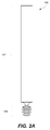
FIG. 2A is a side view of the article ofFIG. 1 ; -
FIGS. 2B and2C are sectional views of a portion of the article ofFIG. 2A ; -
FIG. 3 is a process flow chart corresponding to a method of filling an opening in an object or of filling an opening in an object and friction stir welding the object; -
FIG. 4A is a schematic top view illustrating an opening formed in an object by a first friction stir weld; -
FIG. 4B is a schematic top view of the object shown inFIG. 4A , with the plug ofFIG. 1 installed in the opening; -
FIG. 4C is a schematic top view of the object shown inFIG. 4B after performing a second friction stir weld through the plug; -
FIG. 5A is a sectional view of a portion of the article shown inFIG. 2A prior to installing a plug thereof into an opening in an object; -
FIG. 5B is a sectional view of the plug shown inFIG. 5A , superimposed over a virtual contour of the object; -
FIG. 5C is a sectional view of the article ofFIG. 1 , with the plug installed in the opening ofFIG. 5A and the second flange of the plug deformed toward the body thereof; -
FIG. 5D is a sectional view of the plug shown inFIG. 5C , installed in the opening, with the shaft decoupled from the plug; -
FIG. 5E is a sectional view of the plug shown inFIG. 5D , installed in the opening, with the trailing end of the plug engaged by a friction stir welding tool; -
FIG. 5F is a sectional view of the object shown inFIG. 5E , with the plug consumed in the second friction stir weld; -
FIG. 5G is a sectional perspective view of the plug shown inFIG. 2A , installed in an opening formed when two objects are friction-stir-welded together; -
FIG. 6 is a photograph of a section of an opening created by a friction-stir-welding c, tool; -
FIG. 7A is a photograph of a top surface of an object having two sets of intersecting friction-stir welds, wherein each intersection includes a consumed plug; -
FIGS. 7B and 7C are photographs of sections of the object ofFIG. 7A illustrating the consumed plugs; -
FIG. 8 is a flow diagram of aircraft production and service methodology; -
FIG. 9 is a block diagram of an aircraft. - In the block diagram(s) referred to above, solid lines connecting various elements and/or components may represent mechanical, electrical, fluid, optical, electromagnetic and other couplings and/or combinations thereof. As used herein, "coupled" means associated directly as well as indirectly. For example, a member A may be directly associated with a member B, or may be indirectly associated therewith, e.g., via another member C. Couplings other than those depicted in the block diagram(s) may also exist. Dashed lines, if any, connecting the various elements and/or components represent couplings similar in function and purpose to those represented by solid lines; however, couplings represented by the dashed lines are either selectively provided or relate to alternative or optional aspects of the disclosure. Likewise, any elements and/or components, represented with dashed lines, indicate alternative or optional aspects of the disclosure. Environmental elements, if any, are represented with dotted lines.
- In the following description, numerous specific details are set forth in order to provide a thorough understanding of the presented concepts. The presented concepts may be practiced without some or all of these specific details. In other instances, well known process operations have not been described in detail so as to not unnecessarily obscure the described concepts. While some concepts will be described in conjunction with the specific examples, it will be understood that these examples are not intended to be limiting.
- Referring, e.g., to
FIGs. 1 ,2A ,2B , and5A , one example of the present disclosure relates to anarticle 100 for filling an opening 404 (FIG. 5A ) in anobject 400. Thearticle 100 includes aplug 106 having abody 112, afirst flange 122, and asecond flange 123. As shown, e.g., inFIG. 2B , thefirst flange 122 is in contact with thebody 112 and extends away from thebody 112. Thesecond flange 123 is in contact with thefirst flange 122 and extends away from thefirst flange 122 and thebody 112. Thesecond flange 123 is configured to deform toward thebody 112 upon installation of theplug 106 into theopening 404. This deformation of thesecond flange 123 rotationally and translationally secures theplug 106 in theopening 404 and consolidates theplug 106 in theopening 404. The deformation of thesecond flange 123 is discussed below, e.g., with reference toFIGS. 5A-5C . In some examples, thefirst flange 122 may remain generally intact during deformation of thesecond flange 123. Thefirst flange 122 and thebody 112 may delimit at least a portion of agap 113 for receiving thesecond flange 123 during the deformation thereof. - Referring, e.g., to
FIG. 2A , in one aspect of the disclosure, which may include at least a portion of the subject matter of any of the preceding and/or following examples and aspects, thearticle 100 also includes ashaft 102 frangibly coupled to theplug 106. Theshaft 102 is decoupled from theplug 106 during installation of theplug 106 into theopening 404, as further described below with reference toFIGS. 5C and5D . For example, theshaft 102 may include anarrow neck 104 connecting theshaft 102 to theplug 106. - Referring to
FIG. 2B , in one aspect of the present disclosure, which may include at least a portion of the subject matter of any of the preceding and/or following examples and aspects, theplug 106 includes a trailingend 108. A portion of the trailingend 108 is configured to protrude above a surface 401 (FIG. 5D ) of theobject 400 when theplug 106 is installed into the opening 404 (FIG. 5A ). Specifically,FIG. 5D illustrates theplug 106 installed in theopening 404 with a portion of the trailingend 108 or, more specifically, a portion of the trailingsurface 110 extending above thesurface 401 of theobject 400. - Referring once again to
FIG. 2B , in one aspect of the disclosure, which may include at least a portion of the subject matter of any of the preceding and/or following examples and aspects, thearticle 100 may also include a third flange124 and afourth flange 125. Thethird flange 124 is in contact with thebody 112 and extends away from thebody 112. Thefourth flange 125 is in contact with thethird flange 124 and extends away from thethird flange 124 and thebody 112. Thefourth flange 125 is configured to deform toward thebody 112 and toward thefirst flange 122 upon installation of theplug 106 into theopening 404 as, for example, shown inFIG. 5C . Similar to the deformation of thesecond flange 123, the deformation of thefourth flange 125 rotationally and translationally secures theplug 106 in theopening 404 and consolidates theplug 106 in theopening 404. Thegap 113 between thefirst flange 122 and thethird flange 124 may have the same size (e.g., volume) as the size (e.g., volume) of thefourth flange 125 to accommodate the deformation of thefourth flange 125 into the gap during the installation of theplug 106 into theopening 404. After the installation, thethird flange 124 may remain generally intact, similar to thefirst flange 122. - The
first flange 122 and thesecond flange 123 of theplug 106 form an arrangement of flanges. When additional arrangements of flanges are present, such as thethird flange 124 and thefourth flange 125, described above, one flange in each of the arrangements may be received into thecorresponding gap 113 in a manner similar to thesecond flange 123 and thefourth flange 125. Theplug 106 may include, e.g., one, two, three, four, five arrangements of flanges, and so on. For example,FIG. 2B illustrates theplug 106 having three such arrangements disposed along thebody 112. The first arrangement is formed by thefirst flange 122 and thesecond flange 123, the second arrangement is formed by thethird flange 124 and thefourth flange 125, and the third arrangement is formed by thefifth flange 126 and thesixth flange 127. Adjacent flanges in contact with thebody 112, e.g., thefirst flange 122 and thethird flange 124, may delimit at least a portion of thegap 113 for receiving, e.g., thefourth flange 125 during the deformation thereof resulting from the installation of theplug 106 into theopening 404. Each additional arrangement of flanges further rotationally and translationally secures theplug 106 into theopening 404. Multiple arrangements of flanges may be distributed along the length of theplug 106, providing frictional interference with theobject 400 at different locations. Furthermore, for a given length of the plug 106 (generally corresponding to the depth of the opening 404), increasing the number of arrangements of flanges allows using smaller flanges that may be easier to deform. - In one aspect of the disclosure, which may include at least a portion of the subject matter of any of the preceding and/or following examples and aspects, the
body 112 may have a frusto-conical shape. Furthermore, the collective taper of the inner flanges, e.g., thefirst flange 122, thethird flange 124, and any other flange in contact with thebody 112, may be substantially the same as the taper of the opening. In one aspect of the disclosure, which may include at least a portion of the subject matter of any of the preceding and/or following examples and aspects, thefourth flange 125 has a smaller diameter than thesecond flange 123. It should be noted that thesecond flange 123 is disposed closer to the trailingend 108 of theplug 106 than thefourth flange 125. This type of theplug 106 may be used for tapered holes. Generally, a volume of each outer flange, e.g., thesecond flange 123, thefourth flange 125, and any other flange not directly in contact with thebody 112, may correspond or, more specifically, may be substantially equal to the volume of acorresponding gap 113 configured to receive such flange. This volume correspondence allows achieve full consolidation of theplug 106 in theopening 404 once the plug is inserted into the opening. Furthermore, the difference between the outer and inner radii of each outer flange, which may be referred to as a length of the flange, may not exceed the height of the corresponding gap configured to receive such flange to ensure that the flange fits into the gap during consolidation of theplug 106 into theopening 404. For example, if the length of the outer flange is greater than the height of the gap, the outer flange may bridge the gap rather than fit inside the gap. - In one aspect of the disclosure, which may include at least a portion of the subject matter of any of the preceding and/or following examples and aspects, the
body 112, thefirst flange 122, and thesecond flange 123 form a monolithic structure. For example, thebody 112, thefirst flange 122, and thesecond flange 123 may be machined from a single piece of parent material. - In another aspect of the disclosure, which may include at least a portion of the subject matter of any of the preceding and/or following examples and aspects, the
body 112, thefirst flange 122, and thesecond flange 123 may be fabricated as separate components and then assembled together. For example, thefirst flange 122 may be removably attached to thebody 112, e.g., with a locational interference fit. Thesecond flange 123 may be removably attached to thefirst flange 122 in a similar manner. In some aspects, the assembly of theplug 106 is performed to accommodate the installation of theplug 106 into theopening 404 of a given size, and the flanges are selected based on the size of theopening 404. In other words, thearticle 100 may be provided as a reconfigurable kit of multiple components. In one aspect, thearticle 100 may be supplied with multiple first flanges having different sizes and/or multiple second flanges having different sizes to accommodate openings of different size. - In one aspect of the disclosure, which may include at least a portion of the subject matter of any of the preceding and/or following examples and aspects, the
body 112, thefirst flange 122, and thesecond flange 123 are made of the same material. For example, thebody 112, thefirst flange 122, and thesecond flange 123 may be all made of aluminum, titanium, steel, bronze, copper, lead, plastic, or any other materials suitable for friction stir welding. In some aspects, the material used for thebody 112, thefirst flange 122, and thesecond flange 123 is the same as the material of theobject 400 containing theopening 404 for receiving theplug 106. - Alternatively, in one aspect of the disclosure, which may include at least a portion of the subject matter of any of the preceding and/or following examples and aspects, the
second flange 123 may be made of a different material than thefirst flange 122. For example, thesecond flange 123 may be made from a material that is softer than the material of thefirst flange 122, thereby allowing thesecond flange 123 to deform while maintaining the structure of thefirst flange 122 substantially intact. Similarly, thebody 112 may be made of a different material than thefirst flange 122 and/or thesecond flange 123. - Referring once again to
FIG. 2B , in one aspect of the disclosure, which may include at least a portion of the subject matter of any of the preceding and/or following examples and aspects, thesecond flange 123 includes aslip feature 140 formed on a trailingouter corner 138 of thesecond flange 123. The slip feature promotes consolidation of thesecond flange 123 into thegap 113 during installation of theplug 106 into theopening 404 by reducing friction between the trailingouter corner 138 ofsecond flange 123 and other surfaces, such as those of theplug 106. For example, during installation of theplug 106 into theopening 404, as illustrated inFIG. 5A , the trailingouter corner 138 may come in contact with a leadingsurface 139 of the trailingend 108 of the plug. In one aspect, theslip feature 140 may be implemented as a radius of thecorner 138 and a chamfer on thecorner 138. - In one aspect of the present disclosure, which may include at least a portion of the subject matter of any of the preceding and/or following examples and aspects, the
second flange 123 includes ananchor feature 136 formed on a leadingouter corner 134 of thesecond flange 123. Theanchor feature 136 is configured to engage the surface of the inside wall of the opening 404 (FIG. 5A ) during insertion of theplug 106 therein. Once engaged with the surface of theopening 404, theanchor feature 134 promotes deformation of thesecond flange 123 away from the direction of insertion of theplug 106 into theopening 404 and toward thebody 112 of the plug into thegap 113. In one aspect, the anchor feature may be an apical edge formed by two intersecting surfaces of thesecond flange 123. - As shown, e.g., in
FIGS. 1 and2C , thefourth flange 125 may include aslip feature 125d formed on a trailingouter corner 125c of thefourth flange 125. Thefourth flange 125 may also include ananchor feature 125b formed on a leadingouter corner 125a of thefourth flange 125. Similarly, thesixth flange 127 may include aslip feature 127d formed on a trailingouter corner 127c of thesixth flange 127. Thesixth flange 127 may also include ananchor feature 127b formed on a leadingouter corner 127a of thesixth flange 127. Likewise, any other outer flange, such as thesecond flange 123, may include a slip feature formed on its trailing outer corner and/or an anchor feature formed on its leading outer corner. - In one aspect of the present disclosure, which may include at least a portion of the subject matter of any of the preceding and/or following examples and aspects flanges, such as the
first flange 122 and thesecond flange 123, have an annular shape or a spiral shape.FIG. 2B illustrates thefirst flange 122 and thesecond flange 123 having annular shapes. Specifically, thefirst flange 122 and thesecond flange 123 are symmetric about a longitudinal axis of the opening 404 (FIG. 5A ). Theplug 106 having annular flanges may be installed into theopening 404 by urging (linearly advancing and/or rotating) theplug 106 into the opening 404 (FIG. 5A ). Theplug 106 having spiral flanges may be installed into theopening 404 by linearly advancing theplug 106 into theopening 404 and/or by rotating theplug 106 around the longitudinal axis of theopening 404. For example, theplug 106 may have spiral flanges that correspond to a helical thread in the exit hole of the weld. - The disclosure and drawing figure(s) describing the operations of the method(s) set forth herein should not be interpreted as necessarily determining a sequence in which the operations are to be performed. Rather, although one illustrative order is indicated, it is to be understood that the sequence of the operations may be modified when appropriate. Additionally, in some aspects of the disclosure, not all operations described herein need be performed.
- As shown in
FIG. 3 , one example of the present disclosure relates to a method of installing theplug 106 into theopening 404 in the object 400 (FIG. 5A ). The method of installing theplug 106 may be a part of the method of friction stir welding theobject 400 described below or may be a standalone method that does not include one or both friction stir welding operations described below. The method of installing theplug 106 may include providing theplug 106 having thebody 112, thefirst flange 122, and the second flange 123 (operation 304). As described above, thefirst flange 122 is in contact with thebody 112 and extends away from thebody 112. Thesecond flange 123 is in contact with thefirst flange 122 and extends away from thefirst flange 122 and thebody 112. The method includes installing theplug 106 into the opening 404 (operation 306) to consolidate theplug 106 in theopening 404 and rotationally and translationally secure theplug 106 in theopening 404. Installing theplug 106 into theopening 404 may include urging theplug 106 into theopening 404 thereby deforming thesecond flange 123 toward the body112 (operation 310). - In one aspect of the disclosure, which may include at least a portion of the subject matter of any of the preceding and/or following examples and aspects, the
second flange 123 includes theanchor feature 136 on the leadingouter corner 134 of thesecond flange 123. As theplug 106 is urged into theopening 404, theanchor feature 136 grips awall 405 of theopening 404, causing thesecond flange 123 to deform toward thebody 112. Various aspects of theanchor feature 136 are described above. - In one aspect of the disclosure, which may include at least a portion of the subject matter of any of the preceding and/or following examples and aspects, the
second flange 123 includes aslip feature 140 on the trailingouter corner 138 of thesecond flange 123. As theplug 106 is urged into theopening 404, theslip feature 140 allows thesecond flange 123 to deform toward thebody 112 by reducing friction between thesecond flange 123 and other elements of theplug 106. Various aspects of theslip feature 140 are described above. - As discussed above, the consolidation of the
plug 106 in theopening 404 may include deforming thesecond flange 123 toward thebody 112. In some aspects, one or more additional outer flanges may be deformed during theoperation 306. Theplug 106 may substantially completely fill theopening 404 and, preferably, leaves substantially no voids in theopening 404 after installation of theplug 106 therein. A sectional view of theplug 106 installed into theopening 404 is shown inFIG. 5D . Theopening 404 may be created, for example, during a friction stir welding operation, as is further described below with reference toFIGS. 4A-4C . -
FIG. 5A illustrates theplug 106 and theobject 400 prior to installing theplug 106 into theopening 404. Referring toFIG. 5B , it is apparent that the radial dimensions of one or more outer flanges, such as thesecond flange 123, exceed those of the corresponding portion(s) of theopening 404. Those skilled in the art will appreciate thatFIG. 5B is a hypothetical sectional view of an overlap between the outer flanges (e.g., the second flange 123) of theplug 106 and animaginary object profile 510. - Accordingly, insertion of the
plug 106 into theopening 404 duringoperation 310 causes one or more outer flanges, e.g., thesecond flange 123, to deform, allowing theplug 106 to be fully inserted into theopening 404. As illustrated inFIG. 5C , the outer flange(s) are deformed into the available gap(s). For example, thesecond flange 123 may be consolidated into the gap between thefirst flange 122 and the trailingend 108. Similarly, thefourth flange 125 may be consolidated into the gap between thefirst flange 122 and thethird flange 124. Additional outer flanges may be deformed into gaps formed between corresponding adjacent inner flanges. Some deformation of theobject 400, the inner flanges (e.g.,flanges plug 106 into theopening 404. - Referring generally to
FIG. 3 , one example of the present disclosure relates to a method of friction stir welding the object 400 (FIG. 5E ). The method includes performing a first friction stir weld 402 (FIG. 4A ) along a first weld path having an exit 403(operation 302). Thefirst friction stir 402 weld causes theopening 404 to form in theobject 400 at theexit 403 of the weld path. The method also includes installing the plug 106 (FIG. 4B ) into the opening 404 (operation 306). Theplug 106 is consolidated in theopening 404 and is rotationally and translationally secured in theopening 404 upon installation. The method also includes performing a second friction stir weld 422 (FIG. 4C ) along a second weld path traversing theopening 404 that contains theplug 106 installed therein (operation 316). The installedplug 106 is at least partially consumed in the secondfriction stir weld 422. - Each of these operations will now be described in more detail.
FIG. 4A is a top schematic view of theobject 400 illustrating a firstfriction stir weld 402 and theopening 404. Theopening 404 is formed at the terminus of the firstfriction stir weld 402 as the welding tool exits theobject 400. A sectional view of theopening 404 is provided inFIG. 5A . In general, theopening 404 may vary in size and profile depending on the design of the weld tool and on the thickness and type of the weld. For example, the weld tool may have tapered threads causing roughness on the side walls of theopening 404. However, not all weld tools have this feature. -
FIG. 4B is a top schematic view of theobject 400 illustrating theplug 106 installed in theopening 404. A sectional view of theplug 106 installed into theopening 404 is depicted inFIG. 5D . Another view of theplug 106 installed into theopening 404 is shown inFIG. 5G . Specifically,FIG. 5G is a sectional perspective view of twoobjects weld 524, with theplug 106 installed into theopening 404 created by theweld 524. Theobjects weld 524 is formed by combining (intermixing) plasticized material from bothobjects -
FIG. 4C is a top schematic view of theobject 400 showing an illustrative secondfriction stir weld 422, with the plug 106(represented as element 424) at least partially consumed therein.FIG. 5F a sectional view of thefriction stir weld 422 with the plug 106 (represented as element 424) at least partially consumed therein. Preferably, theplug 106 is substantially completely integrated into theweld 424. - In one aspect of the disclosure, which may include at least a portion of the subject matter of any of the preceding and/or following examples and aspects, installing the
plug 106 into theopening 404 includes urging theplug 106 into theopening 404 duringoperation 310. - In one aspect of the disclosure, which may include at least a portion of the subject matter of any of the preceding and/or following examples and aspects, urging the
plug 106 into theopening 404 includes applying an impact to the plug 106 (block 312 inFIG. 3 ) and/or applying a torque to the plug 106 (block 314 inFIG. 3 ). The impact may be applied to theshaft 102 frangibly coupled to theplug 106. This impact may decouple theshaft 102 from theplug 106, as shown, e.g., inFIG. 5C . Likewise, the torque applied to the plug may decouple theshaft 102 from theplug 106.FIG. 5D illustrates plug 106 without theshaft 102. - In one aspect of the disclosure, which may include at least a portion of the subject matter of any of the preceding and/or following examples and aspects, the
plug 106 may be consolidated in theopening 404 by deforming the flange 123of theplug 106 toward thebody 112 of theplug 106. For example, theflange 123 may be deformed by urging theplug 106 into the opening 404(operation 310). As discussed above, theplug 106 may include one or more outer flanges, such as thesecond flange 123. - In one aspect of the disclosure, which may include at least a portion of the subject matter of any of the preceding and/or following examples and aspects, the
plug 106 is consolidated in theopening 404 substantially without voids. Deformation of one or more outer flanges toward the body of theplug 106 fills thegaps 113 between the inner flanges (FIG. 2B ). As such, once theplug 106 is installed into theopening 404 in theobject 400, there are substantially no voids between theplug 106 and theobject 400. - In one aspect of the disclosure, which may include at least a portion of the subject matter of any of the preceding and/or following examples and aspects, the
plug 106 comprises the trailingend 108. At least a portion of the trailingend 108 protrudes from theopening 404 above thesurface 401 of theobject 400 when theplug 106 is installed in theopening 404 as, shown, for example, inFIGS. 5D and 5E . The trailingend 108 is urged into theopening 404 by a frictionstir welding tool 512 during the secondfriction stir weld 422, as shown, for example, inFIG. 5E , which is a sectional view of the installedplug 106 illustrating the trailingsurface 110 of the trailingend 108 being engaged by the frictionstir welding tool 512. Through this engagement, theplug 106 is urged into theopening 404, thereby promoting plasticizing of the plug and intermixing it with the parent material of theobject 400. The tapered shape of the trailingsurface 110 facilitates initial engagement of the trailingend 108 of theplug 106 by the frictionstir welding tool 512. In some aspects, to ensure smooth initial engagement of the trailingend 108 of the plug by the friction stir welding tool, a portion of the trailingsurface 110 may protrude below thesurface 401 of theobject 400. -
FIG. 6 is a photograph of a section of anopening 606 within anobject 600 created by friction stir welding. For reference, the top surface of theobject 600 is identified as anelement 602, while the side walls defining theopening 606 are identified as anelement 604. Theopening 606 is shown to have a taper. Theopening 606 also has spirally oriented ribs on theside walls 604, which may be created due to rotation of the welding tool while it is removed from theobject 600. -
FIG. 7A is a photograph of a top surface of anobject 700 having twosets overlaps overlap 708 was cross-sectioned in the Y direction, and the result is presented inFIG. 7B . Theoverlap 718 was cross-sectioned in the X direction, and the result is presented inFIG. 7C. FIGS. 7B and 7C illustrate complete filing of theoverlaps - An aircraft manufacturing and
service method 800 shown inFIG. 8 and anaircraft 900 shown inFIG. 9 will now be described to better illustrate various features of processes and systems presented herein. During pre-production, aircraft manufacturing andservice method 800 may include specification anddesign 802 of the aircraft andmaterial procurement 804. The production phase includes component andsubassembly manufacturing 806 andsystem integration 808 of the aircraft. Thereafter, the aircraft may go through certification anddelivery 810 in order to be placed inservice 812. While in service by a customer, the aircraft is scheduled for routine maintenance and service 814 (which may also include modification, reconfiguration, refurbishment, and so on). While the examples described herein relate generally to servicing of commercial aircraft, they may be practiced at other stages of the aircraft manufacturing andservice method 800. - Each of the processes of aircraft manufacturing and
service method 800 may be performed or carried out by a system integrator, a third party, and/or an operator (e.g., a customer). For the purposes of this description, a system integrator may include, without limitation, any number of aircraft manufacturers and major-system subcontractors; a third party may include, for example, without limitation, any number of vendors, subcontractors, and suppliers; and an operator may be an airline, leasing company, military entity, service organization, and so on. - As shown in
FIG. 9 ,aircraft 900 produced by aircraft manufacturing andservice method 800 may includeairframe 902, interior 906, andmultiple systems 904 and interior 906. Examples ofsystems 904 include one or more ofpropulsion system 908,electrical system 910,hydraulic system 912, andenvironmental system 914. Any number of other systems may be included in this example. Although an aircraft example is shown, the principles of the disclosure may be applied to other industries, such as the automotive industry. - Apparatus and methods embodied herein may be employed during any one or more of the stages of aircraft manufacturing and
service method 800. For example, without limitation, components or subassemblies corresponding to component andsubassembly manufacturing 806 may be fabricated or manufactured in a manner similar to components or subassemblies produced while the aircraft is in service. - Also, various features described herein may be utilized during aircraft component and
subassembly manufacturing 806 and/or duringsystem integration 808, which may expedite assembly of or reducing the cost of the aircraft. In some examples, these features may be utilized while the aircraft is in service, for example, during maintenance andservice 814 of the aircraft. - Different examples and aspects of the apparatus and methods are disclosed herein that include a variety of components, features, and functionality. It should be understood that the various examples and aspects of the apparatus and methods disclosed herein may include any of the components, features, and functionality of any of the other examples and aspects of the apparatus and methods disclosed herein in any combination, and all of such possibilities are intended to be within the spirit and scope of the present disclosure.
- Having the benefit of the teachings presented in the foregoing description and the associated drawings, many modifications of the disclosed subject matter will become apparent to one skilled in the art to which this disclosure pertains. Therefore, it is to be understood that the disclosure is not to be limited to the specific examples and aspects provided and that modifications thereof are intended to be within the scope of the appended claims. Moreover, although the foregoing disclosure and the associated drawings describe certain illustrative combinations of elements and/or functions, it should be appreciated that different combinations of elements and/or functions may be realized without departing from the scope of the appended claims.
- The present application discloses subject matter in accordance with the following numbered clauses.
- Clause A1. An article (100) for filling an opening (404) in an object (400), the article (100) comprising: a plug (106) comprising a body (112), a first flange, and a second flange (123), wherein: the first flange (122) is in contact with the body (112) and extends away from the body (112), the second flange (123) is in contact with the first flange (122) and extends away from the first flange (122) and the body (112), and the second flange (123) is configured to deform toward the body (112) upon installation of the plug (106) into the opening (404) to rotationally and translationally secure the plug (106) in the opening (404) and to consolidate the plug (106) in the opening (404).
- Clause A2. The article (100) of clause A1, further comprising a third flange (124) and a fourth flange (125), wherein: the third flange (124) is in contact with the body (112) and extends away from the body (112), the fourth flange (125) is in contact with the third flange (124) and extends away from the third flange (124) and the body (112), and the fourth flange (125) is configured to deform toward the body (112) and toward the first flange (122) upon installation of the plug into the opening (404) to rotationally and translationally secure the plug in the opening (404) and to consolidate the plug in the opening (404).
- Clause A3. The article (100) of any of clauses A1-A2, wherein the body (112), the first flange (122), and the second flange (123) form a monolithic structure.
- Clause A4. The article (100) of any of clauses A1-A2, wherein the first flange (122) is removably attached to the body (112).
- Clause A5. The article (100) of any of clauses A1-A4, wherein the second flange (123) comprises a slip feature (140) formed on a trailing outer corner (138) of the second flange (123).
- Clause A6. The article (100) of any of clauses A1-A5, wherein the second flange (123) comprises an anchor feature (136) formed on a leading outer corner (134) of the second flange (123).
- Clause A7. The article (100) of any of clauses A1-A6, wherein the plug (106) further comprises a trailing end (108), and wherein a portion of the trailing end (108) is configured to protrude above a surface (401) of the object (400) when the plug (106) is installed into the opening (404) in the object (400).
- Clause A8. The article (100) of any of clause A1-A7, further comprising a shaft (102) frangibly coupled to the plug (106).
- Clause A9. A method of friction stir welding an object (400), the method comprising: performing a first friction stir weld (302) along a first weld path having an exit, wherein an opening (404) is formed in the object (400) at the exit; installing a plug (106) into the opening (404), wherein the plug (106) is consolidated in the opening (404) and is rotationally and translationally secured in the opening (404) upon installation; and performing a second friction stir weld (316) along a second weld path traversing the opening (404) that contains the plug (106) installed therein, wherein the plug (106) is at least partially consumed in the second friction stir weld (422).
- Clause A10. The method of clause A9, wherein installing the plug (106) into the opening (404) comprises urging the plug (106) into the opening (404).
- Clause A11. The method of clause A10, wherein urging the plug (106) into the opening (404) comprises applying an impact to the plug (106).
- Clause A12. The method of clause A11, wherein the impact is applied to a shaft (102) frangibly coupled to the plug (106), and wherein the impact decouples the shaft (102) from the plug (106).
- Clause A13. The method of clause A10, wherein urging the plug (106) into the opening (404) comprises applying a torque to the plug (106).
- Clause A14. The method of any of clauses A9-A13, wherein the plug (106) is consolidated in the opening (404) by deforming a flange of the plug (106) toward a body (112) of the plug (106).
- Clause A15. The method of any of clauses A9-A14, wherein: the plug (106) comprises a trailing end (108), at least a portion of the trailing end (108) protruding from the opening (404) above a surface (401) of the object (400) when the plug (106) is installed in the opening (404), and the trailing end (108) is urged into the opening (404) by a friction stir welding tool during the second friction stir weld (422).
Claims (7)
- A method of friction stir welding an object (400), the method comprising:performing a first friction stir weld (302) along a first weld path having an exit, wherein an opening (404) is formed in the object (400) at the exit;installing a plug (106) into the opening (404), wherein the plug (106) is consolidated in the opening (404) and is rotationally and translationally secured in the opening (404) upon installation; andperforming a second friction stir weld (422) along a second weld path traversing the opening (404) that contains the plug (106) installed therein, wherein the plug (106) is at least partially consumed in the second friction stir weld (422).
- The method of claim 1, wherein installing the plug (106) into the opening (404) comprises urging the plug (106) into the opening (404).
- The method of claim 2, wherein urging the plug (106) into the opening (404) comprises applying an impact to the plug (106).
- The method of claim 3, wherein the impact is applied to a shaft (102) frangibly coupled to the plug (106), and wherein the impact decouples the shaft (102) from the plug (106).
- The method of claim 2, wherein urging the plug (106) into the opening (404) comprises applying a torque to the plug (106).
- The method of any of claims 1-5, wherein the plug (106) is consolidated in the opening (404) by deforming a flange of the plug (106) toward a body (112) of the plug (106).
- The method of any of claims 1-6, wherein:the plug (106) comprises a trailing end (108), at least a portion of the trailing end (108) protruding from the opening (404) above a surface (401) of the object (400) when the plug (106) is installed in the opening (404), andthe trailing end (108) is urged into the opening (404) by a friction stir welding tool during the second friction stir weld (422).
Applications Claiming Priority (2)
| Application Number | Priority Date | Filing Date | Title |
|---|---|---|---|
| US14/043,596 US9056370B1 (en) | 2013-10-01 | 2013-10-01 | Friction stir weld plugs and methods of using thereof |
| EP14187294.5A EP2859982B1 (en) | 2013-10-01 | 2014-10-01 | Friction stir weld plugs |
Related Parent Applications (2)
| Application Number | Title | Priority Date | Filing Date |
|---|---|---|---|
| EP14187294.5A Division-Into EP2859982B1 (en) | 2013-10-01 | 2014-10-01 | Friction stir weld plugs |
| EP14187294.5A Division EP2859982B1 (en) | 2013-10-01 | 2014-10-01 | Friction stir weld plugs |
Publications (2)
| Publication Number | Publication Date |
|---|---|
| EP3120965A1 true EP3120965A1 (en) | 2017-01-25 |
| EP3120965B1 EP3120965B1 (en) | 2020-09-09 |
Family
ID=51862083
Family Applications (3)
| Application Number | Title | Priority Date | Filing Date |
|---|---|---|---|
| EP16181539.4A Active EP3120965B1 (en) | 2013-10-01 | 2014-10-01 | Methods of using friction stir weld plugs |
| EP20167706.9A Pending EP3705225A3 (en) | 2013-10-01 | 2014-10-01 | Plugs and methods of using plugs |
| EP14187294.5A Active EP2859982B1 (en) | 2013-10-01 | 2014-10-01 | Friction stir weld plugs |
Family Applications After (2)
| Application Number | Title | Priority Date | Filing Date |
|---|---|---|---|
| EP20167706.9A Pending EP3705225A3 (en) | 2013-10-01 | 2014-10-01 | Plugs and methods of using plugs |
| EP14187294.5A Active EP2859982B1 (en) | 2013-10-01 | 2014-10-01 | Friction stir weld plugs |
Country Status (8)
| Country | Link |
|---|---|
| US (3) | US9056370B1 (en) |
| EP (3) | EP3120965B1 (en) |
| JP (2) | JP6440982B2 (en) |
| KR (2) | KR102153339B1 (en) |
| CN (1) | CN104511690B (en) |
| BR (1) | BR102014020634B1 (en) |
| CA (2) | CA2858645C (en) |
| RU (1) | RU2676373C2 (en) |
Families Citing this family (14)
| Publication number | Priority date | Publication date | Assignee | Title |
|---|---|---|---|---|
| GB2505195B (en) * | 2012-08-21 | 2018-12-12 | Bae Systems Plc | Joint configuration |
| US9056370B1 (en) | 2013-10-01 | 2015-06-16 | The Boeing Company | Friction stir weld plugs and methods of using thereof |
| DE102014114941A1 (en) * | 2014-10-15 | 2016-04-21 | Endress + Hauser Gmbh + Co. Kg | Hybrid flange |
| TWM506109U (en) * | 2014-12-18 | 2015-08-01 | guo-ji Zhang | Multi-segmented leakage stopping device |
| US20180056436A1 (en) * | 2016-08-26 | 2018-03-01 | The Boeing Company | Systems, methods, and devices for exit hole repair associated with welding operations |
| US20180056439A1 (en) * | 2016-08-26 | 2018-03-01 | The Boeing Company | Systems, methods, and devices for exit hole repair associated with welding operations |
| EP3515647A1 (en) * | 2016-09-22 | 2019-07-31 | Nemak, S.A.B. de C.V. | Method for the production of a cast engine block for a combustion engine and engine block |
| US20180085867A1 (en) * | 2016-09-26 | 2018-03-29 | United Technologies Corporation | Method involving friction plug welding a flange |
| US20180172045A1 (en) * | 2016-12-17 | 2018-06-21 | Ford Global Technologies, Llc | Friction Element Weld Element Modification To Increase Corrosion Resistance of Thermal Mechanical Joint |
| US10532425B2 (en) | 2017-10-16 | 2020-01-14 | The Boeing Company | Repairing holes created in components during bobbin friction stir welding |
| US10478916B2 (en) * | 2017-11-02 | 2019-11-19 | GM Global Technology Operations LLC | Method and apparatus for joining components with friction pins |
| FR3089442B1 (en) * | 2018-12-05 | 2020-12-18 | Airbus Operations Sas | A method of assembling at least two parts by transparency welding, a method of assembling a primary structure of an aircraft mast by transparency welding, the primary structure of an aircraft mast thus obtained and an aircraft comprising said primary structure |
| CN114029608B (en) * | 2021-12-09 | 2023-01-03 | 南昌航空大学 | Thick plate friction stir welding method for aluminum and dissimilar metal |
| CN114951957B (en) * | 2022-06-01 | 2023-04-14 | 中国航空制造技术研究院 | Dissimilar material embedded linear friction welding method |
Citations (4)
| Publication number | Priority date | Publication date | Assignee | Title |
|---|---|---|---|---|
| US4091841A (en) * | 1976-07-14 | 1978-05-30 | Bertea Corporation | Pressure plug and method |
| US5971252A (en) * | 1998-04-30 | 1999-10-26 | The Boeing Company | Friction stir welding process to repair voids in aluminum alloys |
| JP2008087041A (en) * | 2006-10-02 | 2008-04-17 | Nippon Light Metal Co Ltd | Joining method |
| US20130239397A1 (en) * | 2010-11-23 | 2013-09-19 | Centre De Recherche Industrielle Du Quebec | Apparatus and Method for Inserting a Component Through the Surface of a Workpiece |
Family Cites Families (26)
| Publication number | Priority date | Publication date | Assignee | Title |
|---|---|---|---|---|
| US4109691A (en) * | 1977-12-21 | 1978-08-29 | Wilson Floyd Leroy | Combination torque release screw and screw driver |
| DE3831523A1 (en) * | 1988-09-16 | 1990-03-22 | Koenig Verbindungstech Ag | METHOD FOR SEALING A HOLE |
| US5263058A (en) * | 1992-02-20 | 1993-11-16 | Combustion Engineering, Inc. | Projectable plug assembly for core barrel flow hole and installation method therefor |
| GB9310469D0 (en) * | 1993-05-20 | 1993-07-07 | Welding Inst | Friction joining |
| US5622208A (en) * | 1995-09-11 | 1997-04-22 | Polymer Molding, Inc. | Port protector |
| JP3045698B2 (en) * | 1997-11-28 | 2000-05-29 | 昭和アルミニウム株式会社 | Metal material joining method |
| US5975406A (en) * | 1998-02-27 | 1999-11-02 | The Boeing Company | Method to repair voids in aluminum alloys |
| US6206268B1 (en) | 2000-07-13 | 2001-03-27 | Murray W. Mahoney | Friction stir welding pin with internal flow channels |
| US6543671B2 (en) | 2001-09-05 | 2003-04-08 | Lockheed Martin Corporation | Apparatus and method for friction stir welding using filler material |
| JP2003205373A (en) * | 2002-01-10 | 2003-07-22 | Toshiba Corp | Plug for rotary friction welding and rotary friction welding equipment using plug |
| JP3740104B2 (en) * | 2002-08-09 | 2006-02-01 | 三菱重工業株式会社 | Friction welding method |
| US20050045695A1 (en) | 2003-08-29 | 2005-03-03 | Subramanian Pazhayannur Ramanathan | Apparatus and method for friction stir welding using a consumable pin tool |
| US6988651B2 (en) | 2004-02-17 | 2006-01-24 | General Motors Corporation | Friction stir rivet drive system and stir riveting methods |
| US7281647B2 (en) * | 2004-06-22 | 2007-10-16 | Alcoa Inc. | Friction stir weld repair |
| US7624910B2 (en) | 2006-04-17 | 2009-12-01 | Lockheed Martin Corporation | Perforated composites for joining of metallic and composite materials |
| JP4951430B2 (en) * | 2007-07-19 | 2012-06-13 | 光生アルミニューム工業株式会社 | Internal friction welding of pipe members |
| US7946440B2 (en) * | 2007-11-13 | 2011-05-24 | Kvt Koenig, Llc | Two-piece expandable sealing plug |
| RU2418664C1 (en) * | 2009-09-10 | 2011-05-20 | Открытое акционерное общество "Национальный институт авиационных технологий" (ОАО НИАТ) | Method of friction welding with mixing of tee joints and tool to this end |
| CN201694495U (en) | 2010-03-11 | 2011-01-05 | 栓乐多瓶塞有限公司 | Two-piece bottle plug |
| DE102010026667A1 (en) * | 2010-07-09 | 2011-03-10 | Daimler Ag | Welding process comprises providing a first component to be welded, pressing a welding pin extending along a first direction against the first component along the first direction and rotating the welding pin around the first direction |
| US8708628B2 (en) * | 2010-11-23 | 2014-04-29 | Centre De Recherche Industrielle Du Quebec | Insertion component and method for inserting thereof through the surface of a workpiece |
| WO2012107059A1 (en) * | 2011-02-12 | 2012-08-16 | Kvt-Koenig Ag | Closure element for internally pressurized bores in components |
| US8883064B2 (en) * | 2011-06-02 | 2014-11-11 | A. Raymond & Cie | Method of making printed fastener |
| DE102011086791A1 (en) * | 2011-11-22 | 2013-05-23 | Continental Automotive Gmbh | Closing method for closing bore of workpiece using bore closing device, involves placing bore in workpiece, where bore in area of workpiece near to surface has bigger diameter than in area of workpiece away from surface |
| JP5459339B2 (en) * | 2012-03-22 | 2014-04-02 | 日本軽金属株式会社 | Joining method |
| US9056370B1 (en) | 2013-10-01 | 2015-06-16 | The Boeing Company | Friction stir weld plugs and methods of using thereof |
-
2013
- 2013-10-01 US US14/043,596 patent/US9056370B1/en active Active
-
2014
- 2014-07-16 RU RU2014129288A patent/RU2676373C2/en active
- 2014-07-17 JP JP2014146584A patent/JP6440982B2/en active Active
- 2014-08-05 KR KR1020140100504A patent/KR102153339B1/en active IP Right Grant
- 2014-08-07 CA CA2858645A patent/CA2858645C/en active Active
- 2014-08-07 CA CA2974247A patent/CA2974247C/en active Active
- 2014-08-21 BR BR102014020634-5A patent/BR102014020634B1/en active IP Right Grant
- 2014-09-23 CN CN201410490594.9A patent/CN104511690B/en active Active
- 2014-10-01 EP EP16181539.4A patent/EP3120965B1/en active Active
- 2014-10-01 EP EP20167706.9A patent/EP3705225A3/en active Pending
- 2014-10-01 EP EP14187294.5A patent/EP2859982B1/en active Active
-
2015
- 2015-04-30 US US14/700,384 patent/US9272362B2/en active Active
-
2016
- 2016-01-25 US US15/005,350 patent/US9409253B2/en active Active
-
2018
- 2018-11-14 JP JP2018213653A patent/JP6716667B2/en active Active
-
2020
- 2020-08-27 KR KR1020200108446A patent/KR102192984B1/en active IP Right Grant
Patent Citations (4)
| Publication number | Priority date | Publication date | Assignee | Title |
|---|---|---|---|---|
| US4091841A (en) * | 1976-07-14 | 1978-05-30 | Bertea Corporation | Pressure plug and method |
| US5971252A (en) * | 1998-04-30 | 1999-10-26 | The Boeing Company | Friction stir welding process to repair voids in aluminum alloys |
| JP2008087041A (en) * | 2006-10-02 | 2008-04-17 | Nippon Light Metal Co Ltd | Joining method |
| US20130239397A1 (en) * | 2010-11-23 | 2013-09-19 | Centre De Recherche Industrielle Du Quebec | Apparatus and Method for Inserting a Component Through the Surface of a Workpiece |
Also Published As
| Publication number | Publication date |
|---|---|
| CA2858645C (en) | 2017-09-19 |
| KR20200105642A (en) | 2020-09-08 |
| JP2019063873A (en) | 2019-04-25 |
| EP2859982B1 (en) | 2020-04-08 |
| EP3120965B1 (en) | 2020-09-09 |
| US9272362B2 (en) | 2016-03-01 |
| CA2974247A1 (en) | 2015-04-01 |
| BR102014020634A2 (en) | 2016-02-10 |
| EP2859982A3 (en) | 2016-01-27 |
| CN104511690A (en) | 2015-04-15 |
| CA2974247C (en) | 2020-09-22 |
| CN104511690B (en) | 2018-03-27 |
| KR102153339B1 (en) | 2020-09-10 |
| EP3705225A2 (en) | 2020-09-09 |
| US9056370B1 (en) | 2015-06-16 |
| KR102192984B1 (en) | 2020-12-21 |
| RU2014129288A (en) | 2016-02-10 |
| JP2015071188A (en) | 2015-04-16 |
| US20160136754A1 (en) | 2016-05-19 |
| RU2676373C2 (en) | 2018-12-28 |
| EP2859982A2 (en) | 2015-04-15 |
| US9409253B2 (en) | 2016-08-09 |
| KR20150039080A (en) | 2015-04-09 |
| US20150231733A1 (en) | 2015-08-20 |
| JP6440982B2 (en) | 2018-12-19 |
| EP3705225A3 (en) | 2020-10-21 |
| JP6716667B2 (en) | 2020-07-01 |
| CA2858645A1 (en) | 2015-04-01 |
| BR102014020634B1 (en) | 2021-01-12 |
Similar Documents
| Publication | Publication Date | Title |
|---|---|---|
| US9409253B2 (en) | Friction stir weld plugs and methods of using thereof | |
| US8540134B2 (en) | Reinforcement of friction plug welds | |
| US10195696B2 (en) | Method and apparatus for increasing the quality of the weld seam in friction stir welding | |
| US11278986B2 (en) | Repairing holes created in components during bobbin friction stir welding | |
| US8333314B2 (en) | Structure for joining members | |
| TW202227725A (en) | Fastener installation system | |
| US8894011B1 (en) | Aircraft fuselage constructed of aircraft fuselage sections screwed together | |
| JP6920055B2 (en) | One-sided fastener assembly and its installation method and system | |
| JP2021110458A (en) | Conductively coated fastening systems for full size determinant assembly (fsda) | |
| US11255339B2 (en) | Fan structure having integrated rotor impeller, and methods of producing the same | |
| CN205254152U (en) | Flange positioning system | |
| US20060010689A1 (en) | Automated drill process for two-diameter holes in multi-layer variable thickness composite materials | |
| EP2644909A1 (en) | Rivet sleeve, blind rivet arrangement and method for releasing the same |
Legal Events
| Date | Code | Title | Description |
|---|---|---|---|
| PUAI | Public reference made under article 153(3) epc to a published international application that has entered the european phase |
Free format text: ORIGINAL CODE: 0009012 |
|
| STAA | Information on the status of an ep patent application or granted ep patent |
Free format text: STATUS: REQUEST FOR EXAMINATION WAS MADE |
|
| 17P | Request for examination filed |
Effective date: 20160727 |
|
| AC | Divisional application: reference to earlier application |
Ref document number: 2859982 Country of ref document: EP Kind code of ref document: P |
|
| AK | Designated contracting states |
Kind code of ref document: A1 Designated state(s): AL AT BE BG CH CY CZ DE DK EE ES FI FR GB GR HR HU IE IS IT LI LT LU LV MC MK MT NL NO PL PT RO RS SE SI SK SM TR |
|
| AX | Request for extension of the european patent |
Extension state: BA ME |
|
| RIC1 | Information provided on ipc code assigned before grant |
Ipc: F16L 55/11 20060101ALI20191009BHEP Ipc: B23K 20/12 20060101AFI20191009BHEP Ipc: B23K 35/02 20060101ALI20191009BHEP Ipc: F16L 55/16 20060101ALI20191009BHEP |
|
| GRAP | Despatch of communication of intention to grant a patent |
Free format text: ORIGINAL CODE: EPIDOSNIGR1 |
|
| STAA | Information on the status of an ep patent application or granted ep patent |
Free format text: STATUS: GRANT OF PATENT IS INTENDED |
|
| INTG | Intention to grant announced |
Effective date: 20191121 |
|
| GRAJ | Information related to disapproval of communication of intention to grant by the applicant or resumption of examination proceedings by the epo deleted |
Free format text: ORIGINAL CODE: EPIDOSDIGR1 |
|
| STAA | Information on the status of an ep patent application or granted ep patent |
Free format text: STATUS: REQUEST FOR EXAMINATION WAS MADE |
|
| GRAP | Despatch of communication of intention to grant a patent |
Free format text: ORIGINAL CODE: EPIDOSNIGR1 |
|
| STAA | Information on the status of an ep patent application or granted ep patent |
Free format text: STATUS: GRANT OF PATENT IS INTENDED |
|
| INTG | Intention to grant announced |
Effective date: 20200327 |
|
| GRAS | Grant fee paid |
Free format text: ORIGINAL CODE: EPIDOSNIGR3 |
|
| GRAA | (expected) grant |
Free format text: ORIGINAL CODE: 0009210 |
|
| STAA | Information on the status of an ep patent application or granted ep patent |
Free format text: STATUS: THE PATENT HAS BEEN GRANTED |
|
| AC | Divisional application: reference to earlier application |
Ref document number: 2859982 Country of ref document: EP Kind code of ref document: P |
|
| AK | Designated contracting states |
Kind code of ref document: B1 Designated state(s): AL AT BE BG CH CY CZ DE DK EE ES FI FR GB GR HR HU IE IS IT LI LT LU LV MC MK MT NL NO PL PT RO RS SE SI SK SM TR |
|
| REG | Reference to a national code |
Ref country code: GB Ref legal event code: FG4D |
|
| REG | Reference to a national code |
Ref country code: AT Ref legal event code: REF Ref document number: 1310964 Country of ref document: AT Kind code of ref document: T Effective date: 20200915 Ref country code: CH Ref legal event code: EP |
|
| REG | Reference to a national code |
Ref country code: DE Ref legal event code: R096 Ref document number: 602014070147 Country of ref document: DE |
|
| REG | Reference to a national code |
Ref country code: IE Ref legal event code: FG4D |
|
| REG | Reference to a national code |
Ref country code: LT Ref legal event code: MG4D |
|
| PG25 | Lapsed in a contracting state [announced via postgrant information from national office to epo] |
Ref country code: SE Free format text: LAPSE BECAUSE OF FAILURE TO SUBMIT A TRANSLATION OF THE DESCRIPTION OR TO PAY THE FEE WITHIN THE PRESCRIBED TIME-LIMIT Effective date: 20200909 Ref country code: HR Free format text: LAPSE BECAUSE OF FAILURE TO SUBMIT A TRANSLATION OF THE DESCRIPTION OR TO PAY THE FEE WITHIN THE PRESCRIBED TIME-LIMIT Effective date: 20200909 Ref country code: LT Free format text: LAPSE BECAUSE OF FAILURE TO SUBMIT A TRANSLATION OF THE DESCRIPTION OR TO PAY THE FEE WITHIN THE PRESCRIBED TIME-LIMIT Effective date: 20200909 Ref country code: GR Free format text: LAPSE BECAUSE OF FAILURE TO SUBMIT A TRANSLATION OF THE DESCRIPTION OR TO PAY THE FEE WITHIN THE PRESCRIBED TIME-LIMIT Effective date: 20201210 Ref country code: FI Free format text: LAPSE BECAUSE OF FAILURE TO SUBMIT A TRANSLATION OF THE DESCRIPTION OR TO PAY THE FEE WITHIN THE PRESCRIBED TIME-LIMIT Effective date: 20200909 Ref country code: BG Free format text: LAPSE BECAUSE OF FAILURE TO SUBMIT A TRANSLATION OF THE DESCRIPTION OR TO PAY THE FEE WITHIN THE PRESCRIBED TIME-LIMIT Effective date: 20201209 Ref country code: NO Free format text: LAPSE BECAUSE OF FAILURE TO SUBMIT A TRANSLATION OF THE DESCRIPTION OR TO PAY THE FEE WITHIN THE PRESCRIBED TIME-LIMIT Effective date: 20201209 |
|
| REG | Reference to a national code |
Ref country code: AT Ref legal event code: MK05 Ref document number: 1310964 Country of ref document: AT Kind code of ref document: T Effective date: 20200909 |
|
| REG | Reference to a national code |
Ref country code: NL Ref legal event code: MP Effective date: 20200909 |
|
| PG25 | Lapsed in a contracting state [announced via postgrant information from national office to epo] |
Ref country code: PL Free format text: LAPSE BECAUSE OF FAILURE TO SUBMIT A TRANSLATION OF THE DESCRIPTION OR TO PAY THE FEE WITHIN THE PRESCRIBED TIME-LIMIT Effective date: 20200909 Ref country code: RS Free format text: LAPSE BECAUSE OF FAILURE TO SUBMIT A TRANSLATION OF THE DESCRIPTION OR TO PAY THE FEE WITHIN THE PRESCRIBED TIME-LIMIT Effective date: 20200909 Ref country code: LV Free format text: LAPSE BECAUSE OF FAILURE TO SUBMIT A TRANSLATION OF THE DESCRIPTION OR TO PAY THE FEE WITHIN THE PRESCRIBED TIME-LIMIT Effective date: 20200909 |
|
| PG25 | Lapsed in a contracting state [announced via postgrant information from national office to epo] |
Ref country code: EE Free format text: LAPSE BECAUSE OF FAILURE TO SUBMIT A TRANSLATION OF THE DESCRIPTION OR TO PAY THE FEE WITHIN THE PRESCRIBED TIME-LIMIT Effective date: 20200909 Ref country code: NL Free format text: LAPSE BECAUSE OF FAILURE TO SUBMIT A TRANSLATION OF THE DESCRIPTION OR TO PAY THE FEE WITHIN THE PRESCRIBED TIME-LIMIT Effective date: 20200909 Ref country code: CZ Free format text: LAPSE BECAUSE OF FAILURE TO SUBMIT A TRANSLATION OF THE DESCRIPTION OR TO PAY THE FEE WITHIN THE PRESCRIBED TIME-LIMIT Effective date: 20200909 Ref country code: PT Free format text: LAPSE BECAUSE OF FAILURE TO SUBMIT A TRANSLATION OF THE DESCRIPTION OR TO PAY THE FEE WITHIN THE PRESCRIBED TIME-LIMIT Effective date: 20210111 Ref country code: SM Free format text: LAPSE BECAUSE OF FAILURE TO SUBMIT A TRANSLATION OF THE DESCRIPTION OR TO PAY THE FEE WITHIN THE PRESCRIBED TIME-LIMIT Effective date: 20200909 Ref country code: RO Free format text: LAPSE BECAUSE OF FAILURE TO SUBMIT A TRANSLATION OF THE DESCRIPTION OR TO PAY THE FEE WITHIN THE PRESCRIBED TIME-LIMIT Effective date: 20200909 |
|
| PG25 | Lapsed in a contracting state [announced via postgrant information from national office to epo] |
Ref country code: ES Free format text: LAPSE BECAUSE OF FAILURE TO SUBMIT A TRANSLATION OF THE DESCRIPTION OR TO PAY THE FEE WITHIN THE PRESCRIBED TIME-LIMIT Effective date: 20200909 Ref country code: AT Free format text: LAPSE BECAUSE OF FAILURE TO SUBMIT A TRANSLATION OF THE DESCRIPTION OR TO PAY THE FEE WITHIN THE PRESCRIBED TIME-LIMIT Effective date: 20200909 Ref country code: AL Free format text: LAPSE BECAUSE OF FAILURE TO SUBMIT A TRANSLATION OF THE DESCRIPTION OR TO PAY THE FEE WITHIN THE PRESCRIBED TIME-LIMIT Effective date: 20200909 Ref country code: IS Free format text: LAPSE BECAUSE OF FAILURE TO SUBMIT A TRANSLATION OF THE DESCRIPTION OR TO PAY THE FEE WITHIN THE PRESCRIBED TIME-LIMIT Effective date: 20210109 |
|
| REG | Reference to a national code |
Ref country code: CH Ref legal event code: PL |
|
| REG | Reference to a national code |
Ref country code: DE Ref legal event code: R097 Ref document number: 602014070147 Country of ref document: DE |
|
| PG25 | Lapsed in a contracting state [announced via postgrant information from national office to epo] |
Ref country code: SK Free format text: LAPSE BECAUSE OF FAILURE TO SUBMIT A TRANSLATION OF THE DESCRIPTION OR TO PAY THE FEE WITHIN THE PRESCRIBED TIME-LIMIT Effective date: 20200909 Ref country code: LU Free format text: LAPSE BECAUSE OF NON-PAYMENT OF DUE FEES Effective date: 20201001 Ref country code: MC Free format text: LAPSE BECAUSE OF FAILURE TO SUBMIT A TRANSLATION OF THE DESCRIPTION OR TO PAY THE FEE WITHIN THE PRESCRIBED TIME-LIMIT Effective date: 20200909 |
|
| REG | Reference to a national code |
Ref country code: BE Ref legal event code: MM Effective date: 20201031 |
|
| PLBE | No opposition filed within time limit |
Free format text: ORIGINAL CODE: 0009261 |
|
| STAA | Information on the status of an ep patent application or granted ep patent |
Free format text: STATUS: NO OPPOSITION FILED WITHIN TIME LIMIT |
|
| 26N | No opposition filed |
Effective date: 20210610 |
|
| PG25 | Lapsed in a contracting state [announced via postgrant information from national office to epo] |
Ref country code: LI Free format text: LAPSE BECAUSE OF NON-PAYMENT OF DUE FEES Effective date: 20201031 Ref country code: SI Free format text: LAPSE BECAUSE OF FAILURE TO SUBMIT A TRANSLATION OF THE DESCRIPTION OR TO PAY THE FEE WITHIN THE PRESCRIBED TIME-LIMIT Effective date: 20200909 Ref country code: BE Free format text: LAPSE BECAUSE OF NON-PAYMENT OF DUE FEES Effective date: 20201031 Ref country code: CH Free format text: LAPSE BECAUSE OF NON-PAYMENT OF DUE FEES Effective date: 20201031 Ref country code: DK Free format text: LAPSE BECAUSE OF FAILURE TO SUBMIT A TRANSLATION OF THE DESCRIPTION OR TO PAY THE FEE WITHIN THE PRESCRIBED TIME-LIMIT Effective date: 20200909 |
|
| PG25 | Lapsed in a contracting state [announced via postgrant information from national office to epo] |
Ref country code: IT Free format text: LAPSE BECAUSE OF FAILURE TO SUBMIT A TRANSLATION OF THE DESCRIPTION OR TO PAY THE FEE WITHIN THE PRESCRIBED TIME-LIMIT Effective date: 20200909 Ref country code: IE Free format text: LAPSE BECAUSE OF NON-PAYMENT OF DUE FEES Effective date: 20201001 |
|
| PG25 | Lapsed in a contracting state [announced via postgrant information from national office to epo] |
Ref country code: TR Free format text: LAPSE BECAUSE OF FAILURE TO SUBMIT A TRANSLATION OF THE DESCRIPTION OR TO PAY THE FEE WITHIN THE PRESCRIBED TIME-LIMIT Effective date: 20200909 Ref country code: MT Free format text: LAPSE BECAUSE OF FAILURE TO SUBMIT A TRANSLATION OF THE DESCRIPTION OR TO PAY THE FEE WITHIN THE PRESCRIBED TIME-LIMIT Effective date: 20200909 Ref country code: CY Free format text: LAPSE BECAUSE OF FAILURE TO SUBMIT A TRANSLATION OF THE DESCRIPTION OR TO PAY THE FEE WITHIN THE PRESCRIBED TIME-LIMIT Effective date: 20200909 |
|
| PG25 | Lapsed in a contracting state [announced via postgrant information from national office to epo] |
Ref country code: MK Free format text: LAPSE BECAUSE OF FAILURE TO SUBMIT A TRANSLATION OF THE DESCRIPTION OR TO PAY THE FEE WITHIN THE PRESCRIBED TIME-LIMIT Effective date: 20200909 |
|
| P01 | Opt-out of the competence of the unified patent court (upc) registered |
Effective date: 20230516 |
|
| PGFP | Annual fee paid to national office [announced via postgrant information from national office to epo] |
Ref country code: GB Payment date: 20231027 Year of fee payment: 10 |
|
| PGFP | Annual fee paid to national office [announced via postgrant information from national office to epo] |
Ref country code: FR Payment date: 20231025 Year of fee payment: 10 Ref country code: DE Payment date: 20231027 Year of fee payment: 10 |