EP3112109A1 - Improved preforms and processes for making bag in bottle containers - Google Patents
Improved preforms and processes for making bag in bottle containers Download PDFInfo
- Publication number
- EP3112109A1 EP3112109A1 EP16165318.3A EP16165318A EP3112109A1 EP 3112109 A1 EP3112109 A1 EP 3112109A1 EP 16165318 A EP16165318 A EP 16165318A EP 3112109 A1 EP3112109 A1 EP 3112109A1
- Authority
- EP
- European Patent Office
- Prior art keywords
- preform
- interlock
- outer layer
- inner layer
- layer
- Prior art date
- Legal status (The legal status is an assumption and is not a legal conclusion. Google has not performed a legal analysis and makes no representation as to the accuracy of the status listed.)
- Granted
Links
Images


Classifications
-
- B—PERFORMING OPERATIONS; TRANSPORTING
- B29—WORKING OF PLASTICS; WORKING OF SUBSTANCES IN A PLASTIC STATE IN GENERAL
- B29B—PREPARATION OR PRETREATMENT OF THE MATERIAL TO BE SHAPED; MAKING GRANULES OR PREFORMS; RECOVERY OF PLASTICS OR OTHER CONSTITUENTS OF WASTE MATERIAL CONTAINING PLASTICS
- B29B11/00—Making preforms
- B29B11/06—Making preforms by moulding the material
- B29B11/08—Injection moulding
-
- B—PERFORMING OPERATIONS; TRANSPORTING
- B29—WORKING OF PLASTICS; WORKING OF SUBSTANCES IN A PLASTIC STATE IN GENERAL
- B29B—PREPARATION OR PRETREATMENT OF THE MATERIAL TO BE SHAPED; MAKING GRANULES OR PREFORMS; RECOVERY OF PLASTICS OR OTHER CONSTITUENTS OF WASTE MATERIAL CONTAINING PLASTICS
- B29B11/00—Making preforms
- B29B11/14—Making preforms characterised by structure or composition
-
- B—PERFORMING OPERATIONS; TRANSPORTING
- B29—WORKING OF PLASTICS; WORKING OF SUBSTANCES IN A PLASTIC STATE IN GENERAL
- B29C—SHAPING OR JOINING OF PLASTICS; SHAPING OF MATERIAL IN A PLASTIC STATE, NOT OTHERWISE PROVIDED FOR; AFTER-TREATMENT OF THE SHAPED PRODUCTS, e.g. REPAIRING
- B29C45/00—Injection moulding, i.e. forcing the required volume of moulding material through a nozzle into a closed mould; Apparatus therefor
- B29C45/16—Making multilayered or multicoloured articles
- B29C45/1675—Making multilayered or multicoloured articles using exchangeable mould halves
-
- B—PERFORMING OPERATIONS; TRANSPORTING
- B29—WORKING OF PLASTICS; WORKING OF SUBSTANCES IN A PLASTIC STATE IN GENERAL
- B29C—SHAPING OR JOINING OF PLASTICS; SHAPING OF MATERIAL IN A PLASTIC STATE, NOT OTHERWISE PROVIDED FOR; AFTER-TREATMENT OF THE SHAPED PRODUCTS, e.g. REPAIRING
- B29C49/00—Blow-moulding, i.e. blowing a preform or parison to a desired shape within a mould; Apparatus therefor
- B29C49/071—Preforms or parisons characterised by their configuration, e.g. geometry, dimensions or physical properties
-
- B—PERFORMING OPERATIONS; TRANSPORTING
- B29—WORKING OF PLASTICS; WORKING OF SUBSTANCES IN A PLASTIC STATE IN GENERAL
- B29C—SHAPING OR JOINING OF PLASTICS; SHAPING OF MATERIAL IN A PLASTIC STATE, NOT OTHERWISE PROVIDED FOR; AFTER-TREATMENT OF THE SHAPED PRODUCTS, e.g. REPAIRING
- B29C49/00—Blow-moulding, i.e. blowing a preform or parison to a desired shape within a mould; Apparatus therefor
- B29C49/08—Biaxial stretching during blow-moulding
- B29C49/10—Biaxial stretching during blow-moulding using mechanical means for prestretching
- B29C49/12—Stretching rods
-
- B—PERFORMING OPERATIONS; TRANSPORTING
- B29—WORKING OF PLASTICS; WORKING OF SUBSTANCES IN A PLASTIC STATE IN GENERAL
- B29C—SHAPING OR JOINING OF PLASTICS; SHAPING OF MATERIAL IN A PLASTIC STATE, NOT OTHERWISE PROVIDED FOR; AFTER-TREATMENT OF THE SHAPED PRODUCTS, e.g. REPAIRING
- B29C49/00—Blow-moulding, i.e. blowing a preform or parison to a desired shape within a mould; Apparatus therefor
- B29C49/42—Component parts, details or accessories; Auxiliary operations
- B29C49/64—Heating or cooling preforms, parisons or blown articles
-
- B—PERFORMING OPERATIONS; TRANSPORTING
- B29—WORKING OF PLASTICS; WORKING OF SUBSTANCES IN A PLASTIC STATE IN GENERAL
- B29C—SHAPING OR JOINING OF PLASTICS; SHAPING OF MATERIAL IN A PLASTIC STATE, NOT OTHERWISE PROVIDED FOR; AFTER-TREATMENT OF THE SHAPED PRODUCTS, e.g. REPAIRING
- B29C49/00—Blow-moulding, i.e. blowing a preform or parison to a desired shape within a mould; Apparatus therefor
- B29C49/42—Component parts, details or accessories; Auxiliary operations
- B29C49/70—Removing or ejecting blown articles from the mould
-
- B—PERFORMING OPERATIONS; TRANSPORTING
- B65—CONVEYING; PACKING; STORING; HANDLING THIN OR FILAMENTARY MATERIAL
- B65D—CONTAINERS FOR STORAGE OR TRANSPORT OF ARTICLES OR MATERIALS, e.g. BAGS, BARRELS, BOTTLES, BOXES, CANS, CARTONS, CRATES, DRUMS, JARS, TANKS, HOPPERS, FORWARDING CONTAINERS; ACCESSORIES, CLOSURES, OR FITTINGS THEREFOR; PACKAGING ELEMENTS; PACKAGES
- B65D1/00—Containers having bodies formed in one piece, e.g. by casting metallic material, by moulding plastics, by blowing vitreous material, by throwing ceramic material, by moulding pulped fibrous material, by deep-drawing operations performed on sheet material
- B65D1/02—Bottles or similar containers with necks or like restricted apertures, designed for pouring contents
- B65D1/0207—Bottles or similar containers with necks or like restricted apertures, designed for pouring contents characterised by material, e.g. composition, physical features
- B65D1/0215—Bottles or similar containers with necks or like restricted apertures, designed for pouring contents characterised by material, e.g. composition, physical features multilayered
-
- B—PERFORMING OPERATIONS; TRANSPORTING
- B29—WORKING OF PLASTICS; WORKING OF SUBSTANCES IN A PLASTIC STATE IN GENERAL
- B29C—SHAPING OR JOINING OF PLASTICS; SHAPING OF MATERIAL IN A PLASTIC STATE, NOT OTHERWISE PROVIDED FOR; AFTER-TREATMENT OF THE SHAPED PRODUCTS, e.g. REPAIRING
- B29C2949/00—Indexing scheme relating to blow-moulding
- B29C2949/07—Preforms or parisons characterised by their configuration
- B29C2949/0715—Preforms or parisons characterised by their configuration the preform having one end closed
-
- B—PERFORMING OPERATIONS; TRANSPORTING
- B29—WORKING OF PLASTICS; WORKING OF SUBSTANCES IN A PLASTIC STATE IN GENERAL
- B29C—SHAPING OR JOINING OF PLASTICS; SHAPING OF MATERIAL IN A PLASTIC STATE, NOT OTHERWISE PROVIDED FOR; AFTER-TREATMENT OF THE SHAPED PRODUCTS, e.g. REPAIRING
- B29C2949/00—Indexing scheme relating to blow-moulding
- B29C2949/07—Preforms or parisons characterised by their configuration
- B29C2949/076—Preforms or parisons characterised by their configuration characterised by the shape
- B29C2949/0768—Preforms or parisons characterised by their configuration characterised by the shape characterised by the shape of specific parts of preform
- B29C2949/078—Preforms or parisons characterised by their configuration characterised by the shape characterised by the shape of specific parts of preform characterised by the bottom
-
- B—PERFORMING OPERATIONS; TRANSPORTING
- B29—WORKING OF PLASTICS; WORKING OF SUBSTANCES IN A PLASTIC STATE IN GENERAL
- B29C—SHAPING OR JOINING OF PLASTICS; SHAPING OF MATERIAL IN A PLASTIC STATE, NOT OTHERWISE PROVIDED FOR; AFTER-TREATMENT OF THE SHAPED PRODUCTS, e.g. REPAIRING
- B29C2949/00—Indexing scheme relating to blow-moulding
- B29C2949/20—Preforms or parisons whereby a specific part is made of only one component, e.g. only one layer
- B29C2949/22—Preforms or parisons whereby a specific part is made of only one component, e.g. only one layer at neck portion
-
- B—PERFORMING OPERATIONS; TRANSPORTING
- B29—WORKING OF PLASTICS; WORKING OF SUBSTANCES IN A PLASTIC STATE IN GENERAL
- B29C—SHAPING OR JOINING OF PLASTICS; SHAPING OF MATERIAL IN A PLASTIC STATE, NOT OTHERWISE PROVIDED FOR; AFTER-TREATMENT OF THE SHAPED PRODUCTS, e.g. REPAIRING
- B29C2949/00—Indexing scheme relating to blow-moulding
- B29C2949/30—Preforms or parisons made of several components
- B29C2949/3016—Preforms or parisons made of several components at body portion
-
- B—PERFORMING OPERATIONS; TRANSPORTING
- B29—WORKING OF PLASTICS; WORKING OF SUBSTANCES IN A PLASTIC STATE IN GENERAL
- B29C—SHAPING OR JOINING OF PLASTICS; SHAPING OF MATERIAL IN A PLASTIC STATE, NOT OTHERWISE PROVIDED FOR; AFTER-TREATMENT OF THE SHAPED PRODUCTS, e.g. REPAIRING
- B29C2949/00—Indexing scheme relating to blow-moulding
- B29C2949/30—Preforms or parisons made of several components
- B29C2949/302—Preforms or parisons made of several components at bottom portion
-
- B—PERFORMING OPERATIONS; TRANSPORTING
- B29—WORKING OF PLASTICS; WORKING OF SUBSTANCES IN A PLASTIC STATE IN GENERAL
- B29C—SHAPING OR JOINING OF PLASTICS; SHAPING OF MATERIAL IN A PLASTIC STATE, NOT OTHERWISE PROVIDED FOR; AFTER-TREATMENT OF THE SHAPED PRODUCTS, e.g. REPAIRING
- B29C2949/00—Indexing scheme relating to blow-moulding
- B29C2949/30—Preforms or parisons made of several components
- B29C2949/3024—Preforms or parisons made of several components characterised by the number of components or by the manufacturing technique
- B29C2949/3026—Preforms or parisons made of several components characterised by the number of components or by the manufacturing technique having two or more components
-
- B—PERFORMING OPERATIONS; TRANSPORTING
- B29—WORKING OF PLASTICS; WORKING OF SUBSTANCES IN A PLASTIC STATE IN GENERAL
- B29C—SHAPING OR JOINING OF PLASTICS; SHAPING OF MATERIAL IN A PLASTIC STATE, NOT OTHERWISE PROVIDED FOR; AFTER-TREATMENT OF THE SHAPED PRODUCTS, e.g. REPAIRING
- B29C2949/00—Indexing scheme relating to blow-moulding
- B29C2949/30—Preforms or parisons made of several components
- B29C2949/3032—Preforms or parisons made of several components having components being injected
- B29C2949/3034—Preforms or parisons made of several components having components being injected having two or more components being injected
-
- B—PERFORMING OPERATIONS; TRANSPORTING
- B29—WORKING OF PLASTICS; WORKING OF SUBSTANCES IN A PLASTIC STATE IN GENERAL
- B29C—SHAPING OR JOINING OF PLASTICS; SHAPING OF MATERIAL IN A PLASTIC STATE, NOT OTHERWISE PROVIDED FOR; AFTER-TREATMENT OF THE SHAPED PRODUCTS, e.g. REPAIRING
- B29C2949/00—Indexing scheme relating to blow-moulding
- B29C2949/30—Preforms or parisons made of several components
- B29C2949/3086—Interaction between two or more components, e.g. type of or lack of bonding
- B29C2949/3094—Interaction between two or more components, e.g. type of or lack of bonding preform having at least partially loose components, e.g. at least partially loose layers
-
- B—PERFORMING OPERATIONS; TRANSPORTING
- B29—WORKING OF PLASTICS; WORKING OF SUBSTANCES IN A PLASTIC STATE IN GENERAL
- B29C—SHAPING OR JOINING OF PLASTICS; SHAPING OF MATERIAL IN A PLASTIC STATE, NOT OTHERWISE PROVIDED FOR; AFTER-TREATMENT OF THE SHAPED PRODUCTS, e.g. REPAIRING
- B29C45/00—Injection moulding, i.e. forcing the required volume of moulding material through a nozzle into a closed mould; Apparatus therefor
- B29C45/17—Component parts, details or accessories; Auxiliary operations
- B29C45/40—Removing or ejecting moulded articles
- B29C45/44—Removing or ejecting moulded articles for undercut articles
- B29C45/4421—Removing or ejecting moulded articles for undercut articles using expansible or collapsible cores
-
- B—PERFORMING OPERATIONS; TRANSPORTING
- B29—WORKING OF PLASTICS; WORKING OF SUBSTANCES IN A PLASTIC STATE IN GENERAL
- B29C—SHAPING OR JOINING OF PLASTICS; SHAPING OF MATERIAL IN A PLASTIC STATE, NOT OTHERWISE PROVIDED FOR; AFTER-TREATMENT OF THE SHAPED PRODUCTS, e.g. REPAIRING
- B29C49/00—Blow-moulding, i.e. blowing a preform or parison to a desired shape within a mould; Apparatus therefor
- B29C49/02—Combined blow-moulding and manufacture of the preform or the parison
- B29C49/06—Injection blow-moulding
-
- B—PERFORMING OPERATIONS; TRANSPORTING
- B29—WORKING OF PLASTICS; WORKING OF SUBSTANCES IN A PLASTIC STATE IN GENERAL
- B29L—INDEXING SCHEME ASSOCIATED WITH SUBCLASS B29C, RELATING TO PARTICULAR ARTICLES
- B29L2009/00—Layered products
- B29L2009/001—Layered products the layers being loose
-
- B—PERFORMING OPERATIONS; TRANSPORTING
- B29—WORKING OF PLASTICS; WORKING OF SUBSTANCES IN A PLASTIC STATE IN GENERAL
- B29L—INDEXING SCHEME ASSOCIATED WITH SUBCLASS B29C, RELATING TO PARTICULAR ARTICLES
- B29L2031/00—Other particular articles
- B29L2031/712—Containers; Packaging elements or accessories, Packages
- B29L2031/7128—Bags, sacks, sachets
-
- B—PERFORMING OPERATIONS; TRANSPORTING
- B29—WORKING OF PLASTICS; WORKING OF SUBSTANCES IN A PLASTIC STATE IN GENERAL
- B29L—INDEXING SCHEME ASSOCIATED WITH SUBCLASS B29C, RELATING TO PARTICULAR ARTICLES
- B29L2031/00—Other particular articles
- B29L2031/712—Containers; Packaging elements or accessories, Packages
- B29L2031/7158—Bottles
-
- B—PERFORMING OPERATIONS; TRANSPORTING
- B65—CONVEYING; PACKING; STORING; HANDLING THIN OR FILAMENTARY MATERIAL
- B65D—CONTAINERS FOR STORAGE OR TRANSPORT OF ARTICLES OR MATERIALS, e.g. BAGS, BARRELS, BOTTLES, BOXES, CANS, CARTONS, CRATES, DRUMS, JARS, TANKS, HOPPERS, FORWARDING CONTAINERS; ACCESSORIES, CLOSURES, OR FITTINGS THEREFOR; PACKAGING ELEMENTS; PACKAGES
- B65D1/00—Containers having bodies formed in one piece, e.g. by casting metallic material, by moulding plastics, by blowing vitreous material, by throwing ceramic material, by moulding pulped fibrous material, by deep-drawing operations performed on sheet material
- B65D1/02—Bottles or similar containers with necks or like restricted apertures, designed for pouring contents
- B65D1/0223—Bottles or similar containers with necks or like restricted apertures, designed for pouring contents characterised by shape
- B65D1/0261—Bottom construction
-
- B—PERFORMING OPERATIONS; TRANSPORTING
- B65—CONVEYING; PACKING; STORING; HANDLING THIN OR FILAMENTARY MATERIAL
- B65D—CONTAINERS FOR STORAGE OR TRANSPORT OF ARTICLES OR MATERIALS, e.g. BAGS, BARRELS, BOTTLES, BOXES, CANS, CARTONS, CRATES, DRUMS, JARS, TANKS, HOPPERS, FORWARDING CONTAINERS; ACCESSORIES, CLOSURES, OR FITTINGS THEREFOR; PACKAGING ELEMENTS; PACKAGES
- B65D77/00—Packages formed by enclosing articles or materials in preformed containers, e.g. boxes, cartons, sacks or bags
- B65D77/04—Articles or materials enclosed in two or more containers disposed one within another
- B65D77/06—Liquids or semi-liquids or other materials or articles enclosed in flexible containers disposed within rigid containers
Definitions
- the present invention relates to blow molding and dispensing technologies, and in particular to novel preforms and processes for making bag in bottle containers and delivery systems.
- such bag-in-bottle containers comprise an outer bottle and an inner flexible bag.
- the outer bottle typically includes a resilient side wall portion.
- product from the bag is forced through a dispensing passage, as the inner product bag is collapsed under pressure.
- the inner bag preferably collapses while maintaining a passage for the product contained therein, to the opening, such that product is not trapped in the inner bag, as the inner bag collapses.
- this is achieved by connecting the inner bag to a resilient outer bottle with at least one interlock.
- An interlock is typically located at the bottom of the bottle, in order to avoid product entrapment, but also to hide the interlock and reduce its impact on the aesthetic form of the bottle.
- Such bag-in-bottle containers are typically made via stretch blow-moulding of a preform.
- the preform In order to blow-mould such preforms, the preform is typically heated such that the preform can be formed to the desired shape.
- the interlock must be kept cold, in order to avoid damage and deformation of the interlock, or even separation of the inner and outer layers at the interlock.
- heating elements are positioned in order to heat the preform sides, but not where the valve is positioned.
- heat shielding is typically placed around the interlock, or air is blown on the interlock, in order to limit the temperature increase of the interlock. Since the interlock has to be kept cool during the blowing process, such preforms cannot be blown in standard blow-moulding machines, without significant modification to the blow-moulding machine.
- WO2012/083310 disclose bag-in-bottle containers, preforms for making them, and processes for converting such preforms into containers.
- the present invention relates to a preform comprising: a preform neck, a preform body; and a preform end cap, wherein the body and end cap comprise an inner layer comprising an inner layer inner surface and an inner layer outer surface, an outer layer comprising an outer layer inner surface and an outer layer outer surface, characterised in that outer layer in the end cap comprises an interlock, wherein the interlock comprises a stem and a head, the interlock being connected to the outer layer inner surface by the stem, such that the inner layer and outer layer are connected in the end cap by the interlock and wherein at least part of the stem (41) and head (42) of the interlock (40) is embedded into the inner layer (10).
- the present invention further relates to a bottle formed by blow-moulding the preform.
- the present invention further relates to a process for making the preform, comprising the steps of: forming a first cavity between a preform mould and a first core, wherein the first core comprises the interlock mould-portion, injecting a resin into the first cavity to form the outer layer and the interlock stem and head, leaving the outer layer and interlock stem and head in the preform mould, while replacing the first core with a second core, to form a second cavity between the outer layer and the second core, injecting resin into the second cavity to form the inner layer and form the interlock.
- a preform for forming bag-in-bottle containers while ensuring that the interlock remains intact, without requiring complex processing or heat protection machine changes, can be made by connecting the interlock to the inner surface of the outer layer.
- the term "container” as used herein refers to any hollow article, usually obtained by blow-moulding.
- the containers of the present invention are suitable for use as a container for any kind of matter, but preferably for liquids or other compositions which are fluid.
- the term container does not imply a particular intended use for the article.
- the term “container” as used herein encompasses articles destined to contain cosmetic products (e.g. shampoos, creams, etc), edible products (e.g. milk, soft drink, condiments, etc), chemicals, etc.
- the preforms and containers of the present invention can be practical for laundry, household care, and personal care bottles.
- Preforms comprise a preform neck (50), a preform body (60), and preform end cap (70).
- the preform neck (50) remains substantially undeformed, while the preform body (60) and preform end cap (70) are deformed to form the container body and base.
- the preform end cap (70) refers to the typically curved portion at the base of the preform (1).
- the preform body (60) and preform end cap (70) comprise an inner layer (10) and an outer layer (20). These layers can be separately moulded, and then later brought together and attached at the interlock (40).
- the preform is injection moulded in a single process, with an initial layer being moulded, and the second layer being moulded in connection to the initial layer.
- the inner container must be sealed to the outer container so that there is no leakage of any liquid from the inner container, and so that said liquid does not contact ambient air or any surroundings.
- Such processes are exemplified in figures 4 and 5 .
- a first cavity (200) can be formed by inserting a first core (300) into a preform mould (100).
- the first core (300) can comprise an interlock mould portion (310) which forms the interlock (40) during injection moulding.
- the outer layer (20) and interlock stem (41) and interlock head (42) are then formed by injecting a resin into the first cavity (200).
- the first core (300) can then be removed, while leaving the outer layer (20) and interlock stem (41) and head (42) in the preform mould (100).
- a second cavity (200) can be formed by inserting a second core (500) into the preform mould (100).
- the inner layer (10) can then be formed by injecting a resin into the second cavity (400).
- the interlock (40) is formed as the resin solidifies around the interlock stem (41) and head (42).
- the inner layer (10) can be formed first.
- the preform mould (100) is removed and replaced with a second preform mould, in order to form the second cavity, into which the outer-layer is formed by injecting a resin.
- the preform neck (50) can be formed by providing a neck cavity (700), formed between a neck insert (600) and core (300 or 500).
- the preform neck (50) can be co-formed with the outer-layer (20) or with the inner layer (10).
- the outer layer (20) is formed by injecting a resin into the first cavity (200)
- the preform neck (50) and outer layer (20) are formed together.
- the inner layer (10) is formed by injecting a resin into the first cavity (200)
- the preform neck (50) and inner layer (10) are formed together.
- the preform neck (50) and inner layer (10) are formed together.
- the outer layer (20) is formed by injecting a resin into the second cavity (400)
- the preform neck (50) and outer layer (20) are formed together.
- the inner layer (10) and outer layer (20) of the preform (1) is preferably made using thermoplastic material.
- Any suitable thermoplastic material may be useful herein.
- Such thermoplastic materials may include normally solid polymers and resins, including aliphatic mono- 1-olefins.
- Suitable thermoplastic materials for use in resins to form the inner layer (10) and outer layer (20) include: polymers and copolymers of aliphatic mono-1-olefins, such as ethylene, propylene, butene-1, hexene-1, octene-1, and the like, and blends of these polymers and copolymers. Polymers of aliphatic mono-1-olefins having a maximum of 8 carbon atoms per molecule and no branching nearer the double bond than the fourth position are preferred.
- thermoplastic materials include the acrylonitrile-butadiene-styrene resins, cellulosics, copolymers of ethylene and a vinyl monomer with an acid group such as methacrylic acid, phenoxy polymers, polyamides, including polyamide-imide (PAI), polyamide-based resins, low-density polyethylene, high-density polyethylene, low-density polypropylene, high-density polypropylene, polyethylene terephthalate, and mixtures thereof.
- PAI polyamide-imide
- thermoplastic materials are those selected from the group consisting of polyolefins and derivatives thereof. More preferably the thermoplastic material is selected from the group consisting of polyethylene, including low-density, but particularly high-density polyethylene, polypropylene, polyesters, polyethylene furanoate (PEF), thermoplastic elastomers from polyolefin blends and mixtures thereof.
- polyethylene including low-density, but particularly high-density polyethylene, polypropylene, polyesters, polyethylene furanoate (PEF), thermoplastic elastomers from polyolefin blends and mixtures thereof.
- Suitable polyesters include: such as polyethylene terephthalate (PET), polyethylene naphthalate (PEN), polytrimethylene terephthalate (PTT), poly(trimethylene naphthalate) (PTN), and mixtures thereof, though polyethylene terephthalate is preferred.
- Suitable biodegradable polymers include: polyglycol acetate (PGAc), polylactic acid (PLA); and copolymers and blends thereof.
- thermoplastic materials can be selected from the group consisting of: polyethylene, including low-density, but particularly high-density polyethylene, polypropylene, polyethylene furanoate (PEF), thermoplastic elastomers from polyolefin blends, polyethylene terephthalate (PET), polyethylene naphthalate (PEN), polytrimethylene terephthalate (PTT), poly(trimethylene naphthalate) (PTN), polyglycol acetate (PGAc), polylactic acid (PLA), and mixtures thereof.
- the inner layer (10) and outer layer (20) can be made from the same thermoplastic material or different thermoplastic material, depending on the desired use of the resultant bottle.
- thermoplastic material used in the resin for forming the inner layer (10) is selected from the group consisting of: polyethylene, including low-density, but particularly high-density polyethylene, polypropylene, and mixtures thereof.
- thermoplastic material used in the resin for forming the outer layer (20) is selected from the group consisting of: polypropylene, polyethylene terephthalate (PET), and mixtures thereof.
- the product may be formed from a virgin resin, a regrind or recycled resin, petroleum derived resins, bio-derived resins from plant materials, and combinations of such resins.
- the containers may comprise fillers and additives in addition to the base resin material.
- Exemplary fillers and additives include colorants, cross-linking polymers, inorganic and organic fillers such as calcium carbonate, opacifiers, and processing aids as these elements are known in the art.
- the preform can be made by a bi-injection molding process (also known as a "two component” or “2C” process, and so used herein), using the same mould.
- the outer layer can first be formed, and then the inner layer can be moulded through an injection point, typically located at or in the bottom of the outer preform.
- the two preforms are then connected to each other at the bottom and at the top.
- the preform can also be made using a 2C process if proper steps are taken to prevent the bonding of the inner container to the outer container, such as the application of a nonstick coating between injections, or selection of material or material thicknesses such that the outer layer does not melt, or additives such as slip agents are included in the resin for the inner layer (10), outer layer (20), or both.
- the inner layer (10) and outer layer (20) of the preform (1) are connected at a bottom portion by an interlock (40).
- the interlock is attached to the outer layer inner surface (21).
- At least part of the stem (41) and head (42) of the interlock (40) is embedded into the inner layer (10). This can be achieved by moulding the outer layer (20) of the preform, together with the interlock (40), and then moulding the inner layer (10) around the interlock (40) in a subsequent step.
- embedded into the inner layer is meant herein that a part of the stem (41) and head (42) of the interlock (40) is fixed into the surrounding inner layer (10).
- the head (42) of the interlock is separated from the outer layer inner surface (21) by the stem (41).
- the head (42) typically has a radial dimension which is greater than the minimum radial dimension of the stem (41), in order to improve the locking of the inner layer (10) to the outer layer at the interlock (40).
- a "radial", direction is one which is measured perpendicular to the axial direction which runs through the centreline of the preform (10), from the opening to the bottom.
- the inner layer (10) is connected to the outer layer (20) via the interlock (40), without requiring any modifications to the oven used to heat the preform in the converting process to form the final bag-in-bottle container.
- the perform (1) of the present invention does not require shielding (such as cool air flow, radiation shield, and the like) of the bottom of the preform (1) in the oven.
- the stem (41) and head (42) of the interlock (40) are typically formed during injection-moulding of the preform (1).
- the head (42) typically has a radial dimension which is greater than the minimum radial dimension of the stem (41), such that the inner layer (10) is “locked” to the outer layer at the interlock (40). This difference in radial dimension is typically referred to as an "undercut”.
- the mould is designed such that the stem (41) and head (42) is released from the mould after forming.
- Undercuts are protrusions or recessions in a part which can prevent the mould, after the preform (1) is formed, from sliding away along the parting direction (demoulding). These features inhibit the direct removal of the core, and as a result, can necessitate using an additional mould piece, such as a collapsible mould core, a side-core, an internal core lifter, and the like, to form the shape of the interlock (40).
- Suitable collapsible mould cores are well known to the skilled person, and include collapsible mini-cores as well as dove-tail collapsible cores.
- Collapsible cores typically comprise internal threads, slots, undercuts, protrusions or cut-outs and incorporate moving parts which can be repositioned after injection moulding, to facilitate the removal of the core from the preform (1).
- the mould core can be pulled out of the outer layer (20) with little or no damage to the stem (41) and head (42) of the interlock.
- the size of the undercut is typically selected based on the choice of materials for the outer layer (20) and inner layer (10), in addition to the overall shape of the inter-lock (40), as is known by the skilled person.
- the preform of the present invention can be used to form a container (2).
- Such containers (2) comprise: a container neck (150), a container body (160), and a container end cap (170).
- the container body (160) and container end cap (170) comprise: an inner layer (110) and an outer layer (220).
- the inner layer (110) comprises an inner layer inner surface (111) and an inner layer outer surface (112).
- the outer layer (220) comprises an outer layer inner surface (221) and an outer layer outer surface (222).
- the inner layer (110) is positioned interior to the outer layer (220).
- the outer layer (220) in the end cap (170) comprises an interlock (40).
- the interlock (40) comprises a stem (41) and a head (42).
- the interlock (40) is connected to the outer layer inner surface (21) by the stem (41), such that the inner layer (110) and outer layer (220) are connected in the end cap (170) by the interlock (40) and wherein at least part of the stem (41) and head (42) of the interlock (40) is embedded into the inner layer (10). Therefore, the interlock is pointing towards the inside of the preform (1).
- the bag-in-bottle container can be obtained by providing the preform of the present invention, bringing said preform to the blow-moulding temperature; fixing the heated preform at the level of the neck region with fixing means in the blow-moulding tool; and blow-moulding the heated preform to form the bag-in-bottle container.
- the inner layer and outer layer of the bag-in-bottle container are connected to one another at the inner layer outer surface and the outer layer inner surface, in addition to at the interlock.
- vents (30) are preferably present, such that the interface between the inner layer outer surface and the outer layer inner surface is in fluid communication with the atmosphere through the vent (30).
- the vent (30) is positioned at or near the preform neck (50), for instance, positioned from 0 mm to 25 mm, preferably from 0 mm to 10 mm, more preferably from 0 mm to 5 mm below the neck (50), the vent (30) is not damaged or deformed when the preform (1) is blown, since the region close to the preform neck (50) undergoes limited or no stretching during blowing.
- the vent (30) may comprise a valve, in order to prevent air from escaping from between the inner layer and outer layer. This can be desirable, for instance, in order to prevent refill of the container, and to ensure that a pump-dispenser, if used, remains charged.
- the interface (24) between inner and outer layers (21) and (22) should release in a consistent and reproducible manner when gas passes through the vent (30).
- the success of said operation depends on a number of parameters, in particular, on the interfacial adhesive strength, in addition to the number, geometry, and distribution of the vents.
- the interfacial strength is of course a key issue and can be modulated by the choice of the material for the inner and outer layers, the thickness of the layers, and by the process parameters during blow-moulding, as is well known to those skilled in the art.
- the pressure-time-temperature window used is of course of prime importance and greatly depends on the material selected for the inner layer (10) and outer layer (20).
- the resin for the inner layer (10) and the resin for the outer layer (20) are typically selected to be different.
- the process parameters during blow-moulding are set such that the interfacial strength between the two layers is sufficiently low that the layers can delaminate during blowing, and/or during use.
- a non-stick agent release agent
- a release agent may be applied at the interface on either or both surfaces of the inner and outer preforms, which are to form the interface of the bag-in-container. Any release agents available on the market and best adapted to the material used for the preform and resisting the blowing temperatures, like silicon- or PTFE-based release agents (e.g., Freekote TM ) may be used.
- the release agent may be applied after injecting the resin to form the first layer, and before injecting the resin to form the second layer. More preferably, the release agent is incorporated into the resin used to form the inner layer (10), the outer layer (20), and combinations thereof.
- a release agent is particularly beneficial with respect to the design of the inner layer. Indeed, lowering the interferential adhesive strength facilitates the lamination of the inner layer from the outer layer and hence reduces stress exerted on the inner layer upon delamination. As such the inner layer can be designed very thin and flexible without risking that the inner layer is damaged upon delamination. Clearly, the flexibility of the inner bag is a key parameter for the liquid dispensing and moreover material savings can be achieved when the inner layer can be designed very thin, and also when the neck (50) is made of the same material as the inner layer (10) (see figure 1 ).
- the container (10) can be made by blow-moulding a preform (1) of the present invention.
- the various methods of blow moulding are well known.
- Injection blow-moulding (IBM) and its variant, injection stretch blow-moulding (ISBM), are commonly used to manufacture high quality hollow articles, such as bottles, on an industrial scale.
- stress-blow moulding what is meant herein is the process in which preforms are heated above their glass transition temperature, and then blown in moulds using high pressure air to form hollow bodies, such as containers or bottles.
- preform is stretched with a core rod as part of the process.
- Glass transition temperature and melt temperature may be conveniently measured with reference to ASTM D3418.
- the process of the present invention comprises the following steps:
- the preform (1) is typically heated above the glass transition temperature of the inner layer (10) and outer layer (20), before stretch-blow moulding, either before placement into the container mould cavity, or while the preform (1) is in the container mould cavity.
- Stretch blow moulding is typically done via injection stretch-blow moulding or reheat stretch-blow moulding where in the latter injection and stretch-blow moulding is done on two separate machines. More information on injection blow-moulding processes can be obtained from general textbooks, for example " The Wiley Encyclopaedia of Packaging Technology", Second Edition (1997), published by Wiley-Interscience Publication (in particular see page 87-89 ).
- the resulting blown container (10) typically has a neck (50), having the same finish with outer threads and other features which may be present on the preform neck (50), such as a lowermost neck flange, snap fit bayonet, and the like.
- the remainder of the bottle undergoes expansion, although to varying degrees, until the container is formed and ejected from the mould.
Abstract
Description
- The present invention relates to blow molding and dispensing technologies, and in particular to novel preforms and processes for making bag in bottle containers and delivery systems.
- When products are dispensed from a container, such as a bottle, air is entrained into the bottle. The result is a reduced product quality due to oxidation, bacterial contamination, loss of volatiles, and the like. Moreover, dispensing of highly viscous products is challenging for standard containers, and often results in non-dispensed residues. Hence, bag-in-bottle type containers have been developed in order to limit air entrainment into the bottle, and enable dispensing of higher viscosity liquids to virtually the last drop.
- Typically, such bag-in-bottle containers comprise an outer bottle and an inner flexible bag. The outer bottle typically includes a resilient side wall portion. When dispensing via squeezing, pumping, and the like, product from the bag is forced through a dispensing passage, as the inner product bag is collapsed under pressure. The inner bag preferably collapses while maintaining a passage for the product contained therein, to the opening, such that product is not trapped in the inner bag, as the inner bag collapses. Typically, this is achieved by connecting the inner bag to a resilient outer bottle with at least one interlock. An interlock is typically located at the bottom of the bottle, in order to avoid product entrapment, but also to hide the interlock and reduce its impact on the aesthetic form of the bottle.
- Such bag-in-bottle containers are typically made via stretch blow-moulding of a preform. In order to blow-mould such preforms, the preform is typically heated such that the preform can be formed to the desired shape. However, during the heating and blowing process, the interlock must be kept cold, in order to avoid damage and deformation of the interlock, or even separation of the inner and outer layers at the interlock. For instance, in
WO2012/083310 A2 , heating elements are positioned in order to heat the preform sides, but not where the valve is positioned. In addition, heat shielding is typically placed around the interlock, or air is blown on the interlock, in order to limit the temperature increase of the interlock. Since the interlock has to be kept cool during the blowing process, such preforms cannot be blown in standard blow-moulding machines, without significant modification to the blow-moulding machine. - Therefore, a need remains for a preform for bag-in-bottle containers, which can be formed into the container without requiring complex processes or machine changes, and to avoid damage to the interlock.
-
WO2012/083310 ,US2,608,320 ,US 4,842,165 andWO2008129016 disclose bag-in-bottle containers, preforms for making them, and processes for converting such preforms into containers. - The present invention relates to a preform comprising: a preform neck, a preform body; and a preform end cap, wherein the body and end cap comprise an inner layer comprising an inner layer inner surface and an inner layer outer surface, an outer layer comprising an outer layer inner surface and an outer layer outer surface, characterised in that outer layer in the end cap comprises an interlock, wherein the interlock comprises a stem and a head, the interlock being connected to the outer layer inner surface by the stem, such that the inner layer and outer layer are connected in the end cap by the interlock and wherein at least part of the stem (41) and head (42) of the interlock (40) is embedded into the inner layer (10).
- The present invention further relates to a bottle formed by blow-moulding the preform.
- The present invention further relates to a process for making the preform, comprising the steps of: forming a first cavity between a preform mould and a first core, wherein the first core comprises the interlock mould-portion, injecting a resin into the first cavity to form the outer layer and the interlock stem and head, leaving the outer layer and interlock stem and head in the preform mould, while replacing the first core with a second core, to form a second cavity between the outer layer and the second core, injecting resin into the second cavity to form the inner layer and form the interlock.
-
-
Figure 1 shows a preform (1), comprising a preform neck (50), preform body (60), and preform end cap (70), the preform body (60) and preform end cap (70) comprising an inner layer (10) and outer layer (20). The inner layer (10) has an inner layer inner surface (11) and an inner layer outer surface (12). The outer layer (20) has an outer layer inner surface (21) and an outer layer outer surface (22). The preform (1) further comprises an interlock (40) comprising a stem (41) and a head (42), attached to the outer layer inner surface (21) at the preform end cap (70). Since the interlock is attached to the outer layer inner surface (21), it is pointing towards the inside of the preform (1). -
Figure 2 shows a detail of the interlock (40) ofFigure 1 . -
Figure 3 shows a detail of a comparative bag-in-bottle preform, in which the interlock comprises a protrusion from the innerlayer throughout the outerlayer, anchoring on the outer surface of the outer layer. As a result, interlock is exposed to the heat applied during the blowing process. -
Figure 4a shows a first cavity (200) formed in the space between the preform mould (100) and first core (300). The first core (300) comprises an interlock mould portion (310). -
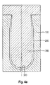
Figure 4b shows an outer-layer (20), formed by injecting a resin into the first cavity (200). The preform mould is so formed as to form a vent (30). The interlock stem (41) and interlock head (42) is formed by the injection of resin into the interlock mould portion (310). The injection point for the resin is not shown, but can be placed in any suitable position. -
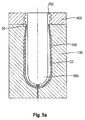
Figure 5a shows a second cavity formed in the space between a second core (500) and the outer layer (20). A neck insert (600) and the top portion of the second core (500) provides a neck cavity (700). -
Figure 5b shows an inner-layer (10) formed by injecting a resin into the first cavity (200), and a preform neck (50) formed by injecting a resin into the neck cavity (700). The interlock (40) is completed by injecting the resin of the inner layer (10) around the interlock stem (41) and head (42). -
Figure 6 shows a container (2), comprising a container neck (150), container body (160), and container end cap (170), the container body (160) and container end cap (170) comprising an inner layer (110) and outer layer (220). The inner layer (110) has an inner layer inner surface (111) and an inner layer outer surface (112). The outer layer (220) has an outer layer inner surface (221) and an outer layer outer surface (222). The container (2) further comprises an interlock (40) comprising a stem (41) and a head (42), attached to the outer layer inner surface (21) at the container end cap (170). - A preform for forming bag-in-bottle containers while ensuring that the interlock remains intact, without requiring complex processing or heat protection machine changes, can be made by connecting the interlock to the inner surface of the outer layer.
- The term "container" as used herein refers to any hollow article, usually obtained by blow-moulding. The containers of the present invention are suitable for use as a container for any kind of matter, but preferably for liquids or other compositions which are fluid. The term container does not imply a particular intended use for the article. For example, the term "container" as used herein encompasses articles destined to contain cosmetic products (e.g. shampoos, creams, etc), edible products (e.g. milk, soft drink, condiments, etc), chemicals, etc. The preforms and containers of the present invention can be practical for laundry, household care, and personal care bottles.
- Preforms comprise a preform neck (50), a preform body (60), and preform end cap (70). During injection stretch blow moulding of the preform, the preform neck (50) remains substantially undeformed, while the preform body (60) and preform end cap (70) are deformed to form the container body and base. The preform end cap (70) refers to the typically curved portion at the base of the preform (1). The preform body (60) and preform end cap (70) comprise an inner layer (10) and an outer layer (20). These layers can be separately moulded, and then later brought together and attached at the interlock (40).
- More preferably, the preform is injection moulded in a single process, with an initial layer being moulded, and the second layer being moulded in connection to the initial layer. Where the inner container must be sealed to the outer container so that there is no leakage of any liquid from the inner container, and so that said liquid does not contact ambient air or any surroundings, such single processes are preferred. Such processes are exemplified in
figures 4 and5 . A first cavity (200) can be formed by inserting a first core (300) into a preform mould (100). The first core (300) can comprise an interlock mould portion (310) which forms the interlock (40) during injection moulding. The outer layer (20) and interlock stem (41) and interlock head (42) are then formed by injecting a resin into the first cavity (200). The first core (300) can then be removed, while leaving the outer layer (20) and interlock stem (41) and head (42) in the preform mould (100). A second cavity (200) can be formed by inserting a second core (500) into the preform mould (100). The inner layer (10) can then be formed by injecting a resin into the second cavity (400). The interlock (40) is formed as the resin solidifies around the interlock stem (41) and head (42). - In an alternative process, the inner layer (10) can be formed first. In such processes, the preform mould (100) is removed and replaced with a second preform mould, in order to form the second cavity, into which the outer-layer is formed by injecting a resin.
- The preform neck (50) can be formed by providing a neck cavity (700), formed between a neck insert (600) and core (300 or 500). The preform neck (50) can be co-formed with the outer-layer (20) or with the inner layer (10). For instance, where the first cavity (200) and neck cavity (700) are present together, and the outer layer (20) is formed by injecting a resin into the first cavity (200), the preform neck (50) and outer layer (20) are formed together. Where the inner layer (10) is formed by injecting a resin into the first cavity (200), the preform neck (50) and inner layer (10) are formed together.
- Alternatively, where the second cavity (400) and neck cavity (700) are present together, and the inner layer (10) is formed by injecting a resin into the second cavity (400), the preform neck (50) and inner layer (10) are formed together. Where the outer layer (20) is formed by injecting a resin into the second cavity (400), the preform neck (50) and outer layer (20) are formed together.
- The inner layer (10) and outer layer (20) of the preform (1) is preferably made using thermoplastic material. Any suitable thermoplastic material may be useful herein. Such thermoplastic materials may include normally solid polymers and resins, including aliphatic mono- 1-olefins.
- Suitable thermoplastic materials for use in resins to form the inner layer (10) and outer layer (20) include: polymers and copolymers of aliphatic mono-1-olefins, such as ethylene, propylene, butene-1, hexene-1, octene-1, and the like, and blends of these polymers and copolymers. Polymers of aliphatic mono-1-olefins having a maximum of 8 carbon atoms per molecule and no branching nearer the double bond than the fourth position are preferred. Other suitable thermoplastic materials include the acrylonitrile-butadiene-styrene resins, cellulosics, copolymers of ethylene and a vinyl monomer with an acid group such as methacrylic acid, phenoxy polymers, polyamides, including polyamide-imide (PAI), polyamide-based resins, low-density polyethylene, high-density polyethylene, low-density polypropylene, high-density polypropylene, polyethylene terephthalate, and mixtures thereof.
- Particularly preferred thermoplastic materials are those selected from the group consisting of polyolefins and derivatives thereof. More preferably the thermoplastic material is selected from the group consisting of polyethylene, including low-density, but particularly high-density polyethylene, polypropylene, polyesters, polyethylene furanoate (PEF), thermoplastic elastomers from polyolefin blends and mixtures thereof.
- Suitable polyesters include: such as polyethylene terephthalate (PET), polyethylene naphthalate (PEN), polytrimethylene terephthalate (PTT), poly(trimethylene naphthalate) (PTN), and mixtures thereof, though polyethylene terephthalate is preferred. Suitable biodegradable polymers include: polyglycol acetate (PGAc), polylactic acid (PLA); and copolymers and blends thereof.
- Preferred thermoplastic materials can be selected from the group consisting of: polyethylene, including low-density, but particularly high-density polyethylene, polypropylene, polyethylene furanoate (PEF), thermoplastic elastomers from polyolefin blends, polyethylene terephthalate (PET), polyethylene naphthalate (PEN), polytrimethylene terephthalate (PTT), poly(trimethylene naphthalate) (PTN), polyglycol acetate (PGAc), polylactic acid (PLA), and mixtures thereof.
- The inner layer (10) and outer layer (20) can be made from the same thermoplastic material or different thermoplastic material, depending on the desired use of the resultant bottle.
- More preferably, the thermoplastic material used in the resin for forming the inner layer (10) is selected from the group consisting of: polyethylene, including low-density, but particularly high-density polyethylene, polypropylene, and mixtures thereof.
- More preferably, the thermoplastic material used in the resin for forming the outer layer (20) is selected from the group consisting of: polypropylene, polyethylene terephthalate (PET), and mixtures thereof.
- The product may be formed from a virgin resin, a regrind or recycled resin, petroleum derived resins, bio-derived resins from plant materials, and combinations of such resins. The containers may comprise fillers and additives in addition to the base resin material. Exemplary fillers and additives include colorants, cross-linking polymers, inorganic and organic fillers such as calcium carbonate, opacifiers, and processing aids as these elements are known in the art.
- Where two different materials which do not bond together are used to make a preform, such as, PET/PP, the preform can be made by a bi-injection molding process (also known as a "two component" or "2C" process, and so used herein), using the same mould. The outer layer can first be formed, and then the inner layer can be moulded through an injection point, typically located at or in the bottom of the outer preform. By virtue of the bi-injection moulding, the two preforms are then connected to each other at the bottom and at the top. If a perform with both layers comprising the same material is desired, e.g., PET/PET, then the preform can also be made using a 2C process if proper steps are taken to prevent the bonding of the inner container to the outer container, such as the application of a nonstick coating between injections, or selection of material or material thicknesses such that the outer layer does not melt, or additives such as slip agents are included in the resin for the inner layer (10), outer layer (20), or both.
- The inner layer (10) and outer layer (20) of the preform (1) are connected at a bottom portion by an interlock (40). The interlock is attached to the outer layer inner surface (21). At least part of the stem (41) and head (42) of the interlock (40) is embedded into the inner layer (10). This can be achieved by moulding the outer layer (20) of the preform, together with the interlock (40), and then moulding the inner layer (10) around the interlock (40) in a subsequent step. By "embedded into the inner layer" is meant herein that a part of the stem (41) and head (42) of the interlock (40) is fixed into the surrounding inner layer (10). The head (42) of the interlock is separated from the outer layer inner surface (21) by the stem (41). The head (42) typically has a radial dimension which is greater than the minimum radial dimension of the stem (41), in order to improve the locking of the inner layer (10) to the outer layer at the interlock (40). A "radial", direction is one which is measured perpendicular to the axial direction which runs through the centreline of the preform (10), from the opening to the bottom.
- As a result, the inner layer (10) is connected to the outer layer (20) via the interlock (40), without requiring any modifications to the oven used to heat the preform in the converting process to form the final bag-in-bottle container. As such the perform (1) of the present invention does not require shielding (such as cool air flow, radiation shield, and the like) of the bottom of the preform (1) in the oven.
- The stem (41) and head (42) of the interlock (40) are typically formed during injection-moulding of the preform (1). As mentioned earlier, the head (42) typically has a radial dimension which is greater than the minimum radial dimension of the stem (41), such that the inner layer (10) is "locked" to the outer layer at the interlock (40). This difference in radial dimension is typically referred to as an "undercut". The mould is designed such that the stem (41) and head (42) is released from the mould after forming.
- Producing moulded preforms (1) with undercuts presents distinct challenges for moulders. Undercuts are protrusions or recessions in a part which can prevent the mould, after the preform (1) is formed, from sliding away along the parting direction (demoulding). These features inhibit the direct removal of the core, and as a result, can necessitate using an additional mould piece, such as a collapsible mould core, a side-core, an internal core lifter, and the like, to form the shape of the interlock (40).
- Suitable collapsible mould cores are well known to the skilled person, and include collapsible mini-cores as well as dove-tail collapsible cores. Collapsible cores typically comprise internal threads, slots, undercuts, protrusions or cut-outs and incorporate moving parts which can be repositioned after injection moulding, to facilitate the removal of the core from the preform (1).
- Alternatively, by limiting the undercut, the difference in size of the head (42) in comparison to the stem (41), the mould core can be pulled out of the outer layer (20) with little or no damage to the stem (41) and head (42) of the interlock. In such cases, the size of the undercut is typically selected based on the choice of materials for the outer layer (20) and inner layer (10), in addition to the overall shape of the inter-lock (40), as is known by the skilled person.
- The preform of the present invention can be used to form a container (2). Such containers (2) comprise: a container neck (150), a container body (160), and a container end cap (170). The container body (160) and container end cap (170) comprise: an inner layer (110) and an outer layer (220). The inner layer (110) comprises an inner layer inner surface (111) and an inner layer outer surface (112). The outer layer (220) comprises an outer layer inner surface (221) and an outer layer outer surface (222). The inner layer (110) is positioned interior to the outer layer (220). The outer layer (220) in the end cap (170) comprises an interlock (40). The interlock (40) comprises a stem (41) and a head (42). The interlock (40) is connected to the outer layer inner surface (21) by the stem (41), such that the inner layer (110) and outer layer (220) are connected in the end cap (170) by the interlock (40) and wherein at least part of the stem (41) and head (42) of the interlock (40) is embedded into the inner layer (10). Therefore, the interlock is pointing towards the inside of the preform (1).
- The bag-in-bottle container can be obtained by providing the preform of the present invention, bringing said preform to the blow-moulding temperature; fixing the heated preform at the level of the neck region with fixing means in the blow-moulding tool; and blow-moulding the heated preform to form the bag-in-bottle container.
- The inner layer and outer layer of the bag-in-bottle container are connected to one another at the inner layer outer surface and the outer layer inner surface, in addition to at the interlock.
- One or more vents (30) are preferably present, such that the interface between the inner layer outer surface and the outer layer inner surface is in fluid communication with the atmosphere through the vent (30). Where the vent (30) is positioned at or near the preform neck (50), for instance, positioned from 0 mm to 25 mm, preferably from 0 mm to 10 mm, more preferably from 0 mm to 5 mm below the neck (50), the vent (30) is not damaged or deformed when the preform (1) is blown, since the region close to the preform neck (50) undergoes limited or no stretching during blowing.
- The vent (30) may comprise a valve, in order to prevent air from escaping from between the inner layer and outer layer. This can be desirable, for instance, in order to prevent refill of the container, and to ensure that a pump-dispenser, if used, remains charged.
- The interface (24) between inner and outer layers (21) and (22) should release in a consistent and reproducible manner when gas passes through the vent (30). The success of said operation depends on a number of parameters, in particular, on the interfacial adhesive strength, in addition to the number, geometry, and distribution of the vents. The interfacial strength is of course a key issue and can be modulated by the choice of the material for the inner and outer layers, the thickness of the layers, and by the process parameters during blow-moulding, as is well known to those skilled in the art. The pressure-time-temperature window used is of course of prime importance and greatly depends on the material selected for the inner layer (10) and outer layer (20). As such, the resin for the inner layer (10) and the resin for the outer layer (20) are typically selected to be different. When the same or similar resins are used for the inner layer (10) and outer layer (20), the process parameters during blow-moulding are set such that the interfacial strength between the two layers is sufficiently low that the layers can delaminate during blowing, and/or during use. Alternatively, or in combination, a non-stick agent (release agent) can be applied at the interface between the two layers, or can be added to the resin of the inner layer (10), outer layer (20), or both.
- A release agent may be applied at the interface on either or both surfaces of the inner and outer preforms, which are to form the interface of the bag-in-container. Any release agents available on the market and best adapted to the material used for the preform and resisting the blowing temperatures, like silicon- or PTFE-based release agents (e.g., Freekote™) may be used. The release agent may be applied after injecting the resin to form the first layer, and before injecting the resin to form the second layer. More preferably, the release agent is incorporated into the resin used to form the inner layer (10), the outer layer (20), and combinations thereof.
- The application of a release agent is particularly beneficial with respect to the design of the inner layer. Indeed, lowering the interferential adhesive strength facilitates the lamination of the inner layer from the outer layer and hence reduces stress exerted on the inner layer upon delamination. As such the inner layer can be designed very thin and flexible without risking that the inner layer is damaged upon delamination. Clearly, the flexibility of the inner bag is a key parameter for the liquid dispensing and moreover material savings can be achieved when the inner layer can be designed very thin, and also when the neck (50) is made of the same material as the inner layer (10) (see
figure 1 ). - The container (10) can be made by blow-moulding a preform (1) of the present invention. The various methods of blow moulding are well known. Injection blow-moulding (IBM) and its variant, injection stretch blow-moulding (ISBM), are commonly used to manufacture high quality hollow articles, such as bottles, on an industrial scale. By "stretch-blow moulding", what is meant herein is the process in which preforms are heated above their glass transition temperature, and then blown in moulds using high pressure air to form hollow bodies, such as containers or bottles. Usually the preform is stretched with a core rod as part of the process.
- Glass transition temperature and melt temperature may be conveniently measured with reference to ASTM D3418.
- The process of the present invention comprises the following steps:
- a) providing a preform (1) according to the present invention, or formed from the processes described herein, into a container mould cavity;
- b) stretch blow moulding the preform (1) to form a container;
- c) ejecting the finished container from the container mould cavity.
- The preform (1) is typically heated above the glass transition temperature of the inner layer (10) and outer layer (20), before stretch-blow moulding, either before placement into the container mould cavity, or while the preform (1) is in the container mould cavity.
- Stretch blow moulding is typically done via injection stretch-blow moulding or reheat stretch-blow moulding where in the latter injection and stretch-blow moulding is done on two separate machines. More information on injection blow-moulding processes can be obtained from general textbooks, for example "The Wiley Encyclopaedia of Packaging Technology", Second Edition (1997), published by Wiley-Interscience Publication (in particular see page 87-89).
- The resulting blown container (10) typically has a neck (50), having the same finish with outer threads and other features which may be present on the preform neck (50), such as a lowermost neck flange, snap fit bayonet, and the like. The remainder of the bottle undergoes expansion, although to varying degrees, until the container is formed and ejected from the mould.
- The dimensions and values disclosed herein are not to be understood as being strictly limited to the exact numerical values recited. Instead, unless otherwise specified, each such dimension is intended to mean both the recited value and a functionally equivalent range surrounding that value. For example, a dimension disclosed as "40 mm" is intended to mean "about 40 mm".
Claims (12)
- A preform (1) comprising:a) a preform neck (50);b) a preform body (60); andc) a preform end cap (70);wherein the body (60) and end cap (70) comprise:i. an inner layer (10) comprising an inner layer inner surface (11) and an inner layer outer surface (12);ii. an outer layer (20) comprising an outer layer inner surface (21) and an outer layer outer surface (22);wherein the inner layer (10) is positioned interior to the outer layer (20),
characterised in that outer layer (20) in the end cap (70) comprises an interlock (40), wherein the interlock (40) comprises a stem (41) and a head (42), the interlock (40) being connected to the outer layer inner surface (21) by the stem (41), such that the inner layer (10) and outer layer (20) are connected in the end cap (70) by the interlock (40) and wherein at least part of the stem (41) and head (42) of the interlock (40) is embedded into the inner layer (10). - The preform (1) according to claim 1, further comprising a vent (30).
- The preform (1) according to claim 2, wherein the vent (30) is not positioned in the preform end cap (70), preferably wherein the vent (30) is positioned closer to the preform neck (50) than the preform end cap (50).
- The preform (1) according to claim 2 or 3, wherein the vent is positioned from 0 mm to 25 mm, preferably from 0 mm to 10 mm, more preferably from 0 mm to 5 mm below the neck (50).
- A container (2) comprising:a) a container neck (150);b) a container body (160); andc) a container end cap (170);wherein the container body (160) and container end cap (170) comprise:i. an inner layer (110) comprising an inner layer inner surface (111) and an inner layer outer surface (112);ii. an outer layer (220) comprising an outer layer inner surface (221) and an outer layer outer surface (222);wherein the inner layer (110) is positioned interior to the outer layer (220),
characterised in that outer layer (220) in the end cap (170) comprises an interlock (40), wherein the interlock (40) comprises a stem (41) and a head (42), the interlock (40) being connected to the outer layer inner surface (21) by the stem (41), such that the inner layer (110) and outer layer (220) are connected in the end cap (170) by the interlock (40) and wherein at least part of the stem (41) and head (42) of the interlock (40) is embedded into the inner layer (10). - A process for making the preform (1) according to claim 1, comprising the steps of:a) forming a first cavity (200) between a preform mould (100) and a first core (300), wherein the first core (300) comprises the interlock mould-portion (310);b) injecting a resin into the first cavity (200) to form the outer layer (20) and the interlock stem (41) and head (42);c) leaving the outer layer (20) and interlock stem (41) and head (42) in the preform mould (100), while replacing the first core (300) with a second core (500), to form a second cavity (400) between the outer layer (20) and the second core (500);d) injecting resin into the second cavity (400) to form the inner layer (10) and form the interlock (40).wherein the preform neck (50) is formed by providing a neck cavity (700) between a preform insert (600) and either the first core (300) or second core (500).
- The process according to claim 6, wherein the interlock mould-portion (310) comprises a means for de-moulding the interlock stem (41) and head (42), preferably a collapsible core.
- The process according to claim 6 or 7, wherein the resin used to form the inner layer (10) and outer layer (20) independently comprises a thermoplastic material selected from the group consisting of: polyethylene, including low-density, but particularly high-density polyethylene, polypropylene, polyethylene furanoate (PEF), thermoplastic elastomers from polyolefin blends, polyethylene terephthalate (PET), polyethylene naphthalate (PEN), polytrimethylene terephthalate (PTT), poly(trimethylene naphthalate) (PTN), polyglycol acetate (PGAc), polylactic acid (PLA), and mixtures thereof.
- The process according to claim 8, wherein:a) the resin used to form the inner layer (10) comprises a thermoplastic material selected from the group consisting of: polyethylene, low-density polyethylene, high-density polyethylene, polypropylene, and mixtures thereof; andb) the resin used to form the outer layer (20) comprises a thermoplastic material selected from the group consisting of: polypropylene, polyethylene terephthalate (PET), and mixtures thereof.
- The process according to claims 6 to 9, wherein at least one of the resins used to form the inner layer (10) and the outer layer (20) comprise a release agent.
- A process for making a container, comprising the steps of:a) providing a preform (1) according to claim 1, or formed from the process of claims 5 to 9, into a container mould cavity;b) stretch blow moulding the preform (1) to form a container;c) ejecting the container from the container mould cavity,wherein the preform (1) is heated before stretch blow moulding.
- The process according to claim 10, wherein no heat shielding or active cooling is applied to the end cap (70).
Priority Applications (4)
| Application Number | Priority Date | Filing Date | Title |
|---|---|---|---|
| US15/160,183 US9981407B2 (en) | 2015-06-29 | 2016-05-20 | Preforms and processes for making bag in bottle containers |
| JP2017567395A JP2018525244A (en) | 2015-06-29 | 2016-06-20 | Improved preform and bag manufacturing process in bottle containers |
| CA2987948A CA2987948C (en) | 2015-06-29 | 2016-06-20 | Improved preforms and processes for making bag in bottle containers |
| PCT/US2016/038286 WO2017003730A1 (en) | 2015-06-29 | 2016-06-20 | Improved preforms and processes for making bag in bottle containers |
Applications Claiming Priority (1)
| Application Number | Priority Date | Filing Date | Title |
|---|---|---|---|
| EP15174199 | 2015-06-29 |
Publications (2)
| Publication Number | Publication Date |
|---|---|
| EP3112109A1 true EP3112109A1 (en) | 2017-01-04 |
| EP3112109B1 EP3112109B1 (en) | 2018-05-23 |
Family
ID=53510669
Family Applications (1)
| Application Number | Title | Priority Date | Filing Date |
|---|---|---|---|
| EP16165318.3A Active EP3112109B1 (en) | 2015-06-29 | 2016-04-14 | Improved preforms and processes for making bag in bottle containers |
Country Status (5)
| Country | Link |
|---|---|
| US (1) | US9981407B2 (en) |
| EP (1) | EP3112109B1 (en) |
| JP (1) | JP2018525244A (en) |
| CA (1) | CA2987948C (en) |
| WO (1) | WO2017003730A1 (en) |
Cited By (1)
| Publication number | Priority date | Publication date | Assignee | Title |
|---|---|---|---|---|
| EP3403805A1 (en) * | 2017-05-16 | 2018-11-21 | Gaplast GmbH | Container with an inner bag |
Families Citing this family (7)
| Publication number | Priority date | Publication date | Assignee | Title |
|---|---|---|---|---|
| DE102017007443A1 (en) * | 2017-08-05 | 2019-02-07 | Kocher-Plastik Maschinenbau Gmbh | Blow molding, filling and closing method and then produced container product, in particular ampoule product |
| EP3513936B1 (en) * | 2018-01-22 | 2021-05-19 | Canon Kabushiki Kaisha | Blown bottle |
| EP3898155A1 (en) | 2018-12-19 | 2021-10-27 | The Procter & Gamble Company | Article with visual effect |
| CN113165214A (en) * | 2018-12-19 | 2021-07-23 | 宝洁公司 | Monolayer blow molded articles having functional, visual, and/or tactile effects and methods of making such articles |
| WO2020132157A1 (en) | 2018-12-19 | 2020-06-25 | The Procter & Gamble Company | Multi-layer blow molded article with functional, visual, and/or tactile effects |
| JP7282465B2 (en) | 2019-05-31 | 2023-05-29 | 株式会社吉野工業所 | Synthetic resin container, synthetic resin container manufacturing method, and laminated preform |
| US11591151B2 (en) * | 2021-07-02 | 2023-02-28 | Owens-Brockway Glass Container Inc. | Pressure relief blow-out plugs and related packages |
Citations (6)
| Publication number | Priority date | Publication date | Assignee | Title |
|---|---|---|---|---|
| US2608320A (en) | 1947-03-31 | 1952-08-26 | Jr Joseph R Harrison | Pump type dispenser with cartridge having flexible and rigid portions |
| US4842165A (en) | 1987-08-28 | 1989-06-27 | The Procter & Gamble Company | Resilient squeeze bottle package for dispensing viscous products without belching |
| EP1593605A1 (en) * | 2003-02-14 | 2005-11-09 | Taisei Kako Co., Ltd. | Laminated releasable bottle and method of producing the same |
| DE60025177T2 (en) * | 1999-10-08 | 2006-07-20 | Taisei Kako Co., Ltd. | PUMP CONTAINER FROM A COMPOUND BOTTLE WITH REMOVABLE INTERIOR LAYER |
| WO2008129016A1 (en) | 2007-04-19 | 2008-10-30 | Inbev S.A. | Integrally blow-moulded bag-in-container having an inner layer and the outer layer made of the same material and preform for making it |
| WO2012083310A2 (en) | 2010-12-17 | 2012-06-21 | Dispensing Technologies B.V. | Improved pre-forms for flair applications |
Family Cites Families (6)
| Publication number | Priority date | Publication date | Assignee | Title |
|---|---|---|---|---|
| CA2509336C (en) * | 1992-05-11 | 2006-10-31 | Yoshino Kogyosho Co., Ltd. | Laminated bottle |
| EP1180424B1 (en) * | 1999-10-08 | 2004-04-21 | Taisei Kako Co., Ltd. | Method of producing laminated bottles having peelable inner layer |
| US20080257847A1 (en) | 2007-04-19 | 2008-10-23 | Inbev S.A. | Integrally blow-moulded bag-in-container having a bag anchoring point; process for the production thereof; and tool therefor |
| NL1034895C2 (en) | 2008-01-08 | 2009-07-13 | Dispensing Technologies Bv | Composite container and method for manufacturing thereof. |
| JP5499540B2 (en) | 2008-08-01 | 2014-05-21 | 株式会社リコー | Image forming apparatus and power supply control method |
| JP5999553B2 (en) | 2012-08-31 | 2016-09-28 | 株式会社吉野工業所 | Method for producing synthetic resin container by biaxial stretch blow molding and container |
-
2016
- 2016-04-14 EP EP16165318.3A patent/EP3112109B1/en active Active
- 2016-05-20 US US15/160,183 patent/US9981407B2/en active Active
- 2016-06-20 WO PCT/US2016/038286 patent/WO2017003730A1/en active Application Filing
- 2016-06-20 CA CA2987948A patent/CA2987948C/en active Active
- 2016-06-20 JP JP2017567395A patent/JP2018525244A/en not_active Withdrawn
Patent Citations (6)
| Publication number | Priority date | Publication date | Assignee | Title |
|---|---|---|---|---|
| US2608320A (en) | 1947-03-31 | 1952-08-26 | Jr Joseph R Harrison | Pump type dispenser with cartridge having flexible and rigid portions |
| US4842165A (en) | 1987-08-28 | 1989-06-27 | The Procter & Gamble Company | Resilient squeeze bottle package for dispensing viscous products without belching |
| DE60025177T2 (en) * | 1999-10-08 | 2006-07-20 | Taisei Kako Co., Ltd. | PUMP CONTAINER FROM A COMPOUND BOTTLE WITH REMOVABLE INTERIOR LAYER |
| EP1593605A1 (en) * | 2003-02-14 | 2005-11-09 | Taisei Kako Co., Ltd. | Laminated releasable bottle and method of producing the same |
| WO2008129016A1 (en) | 2007-04-19 | 2008-10-30 | Inbev S.A. | Integrally blow-moulded bag-in-container having an inner layer and the outer layer made of the same material and preform for making it |
| WO2012083310A2 (en) | 2010-12-17 | 2012-06-21 | Dispensing Technologies B.V. | Improved pre-forms for flair applications |
Non-Patent Citations (1)
| Title |
|---|
| "The Wiley Encyclopaedia of Packaging Technology", 1997, WILEY-INTERSCIENCE PUBLICATION, pages: 87 - 89 |
Cited By (4)
| Publication number | Priority date | Publication date | Assignee | Title |
|---|---|---|---|---|
| EP3403805A1 (en) * | 2017-05-16 | 2018-11-21 | Gaplast GmbH | Container with an inner bag |
| CN108861076A (en) * | 2017-05-16 | 2018-11-23 | 盖普拉斯特股份有限公司 | container with inner bag |
| DE102017004657B4 (en) | 2017-05-16 | 2021-09-23 | Gaplast Gmbh | Container with inner bag |
| CN108861076B (en) * | 2017-05-16 | 2021-11-23 | 盖普拉斯特股份有限公司 | Container with inner bag |
Also Published As
| Publication number | Publication date |
|---|---|
| US9981407B2 (en) | 2018-05-29 |
| CA2987948A1 (en) | 2017-01-05 |
| US20160375608A1 (en) | 2016-12-29 |
| JP2018525244A (en) | 2018-09-06 |
| EP3112109B1 (en) | 2018-05-23 |
| WO2017003730A1 (en) | 2017-01-05 |
| CA2987948C (en) | 2020-01-21 |
Similar Documents
| Publication | Publication Date | Title |
|---|---|---|
| EP3112109B1 (en) | Improved preforms and processes for making bag in bottle containers | |
| CA2682124C (en) | Integrally blow-moulded bag-in-container having a bag anchoring point; process for the production thereof; and tool thereof | |
| US11059214B2 (en) | Container and method of manufacture | |
| US20220396022A1 (en) | Integrally Blow-Moulded Bag-in-Container Having a Bag Anchoring Point, Process for the Production Thereof, and Tool Thereof | |
| US11014280B2 (en) | Preform for producing a plastic container, production of the preform and plastic container produced from the preform, as well as its production | |
| US20100304169A1 (en) | Preform for plastics material bottles or wide-necked vessels | |
| US9981442B2 (en) | Method for producing a multilayered preform and a preform | |
| US9539754B2 (en) | Method of manufacturing an injected and blown product | |
| WO2012097248A1 (en) | A blow molded container | |
| US10807276B2 (en) | Injection molded preform and manufacture thereof | |
| US9114905B2 (en) | Container having a labeled textured surface | |
| US9321228B2 (en) | Process for the manufacture of an article comprising a recess | |
| US9205592B2 (en) | Process for the manufacture of an article comprimising a recess | |
| JP2019072903A (en) | Preform, plastic bottle and method for producing the same | |
| US20170305591A1 (en) | Wide-necked container having an attached threaded sleeve | |
| MX2009005554A (en) | Preform for plastics material bottles or wide-necked vessels. |
Legal Events
| Date | Code | Title | Description |
|---|---|---|---|
| PUAI | Public reference made under article 153(3) epc to a published international application that has entered the european phase |
Free format text: ORIGINAL CODE: 0009012 |
|
| STAA | Information on the status of an ep patent application or granted ep patent |
Free format text: STATUS: THE APPLICATION HAS BEEN PUBLISHED |
|
| AK | Designated contracting states |
Kind code of ref document: A1 Designated state(s): AL AT BE BG CH CY CZ DE DK EE ES FI FR GB GR HR HU IE IS IT LI LT LU LV MC MK MT NL NO PL PT RO RS SE SI SK SM TR |
|
| AX | Request for extension of the european patent |
Extension state: BA ME |
|
| STAA | Information on the status of an ep patent application or granted ep patent |
Free format text: STATUS: REQUEST FOR EXAMINATION WAS MADE |
|
| 17P | Request for examination filed |
Effective date: 20170703 |
|
| RBV | Designated contracting states (corrected) |
Designated state(s): AL AT BE BG CH CY CZ DE DK EE ES FI FR GB GR HR HU IE IS IT LI LT LU LV MC MK MT NL NO PL PT RO RS SE SI SK SM TR |
|
| GRAP | Despatch of communication of intention to grant a patent |
Free format text: ORIGINAL CODE: EPIDOSNIGR1 |
|
| STAA | Information on the status of an ep patent application or granted ep patent |
Free format text: STATUS: GRANT OF PATENT IS INTENDED |
|
| INTG | Intention to grant announced |
Effective date: 20180105 |
|
| GRAS | Grant fee paid |
Free format text: ORIGINAL CODE: EPIDOSNIGR3 |
|
| GRAA | (expected) grant |
Free format text: ORIGINAL CODE: 0009210 |
|
| STAA | Information on the status of an ep patent application or granted ep patent |
Free format text: STATUS: THE PATENT HAS BEEN GRANTED |
|
| AK | Designated contracting states |
Kind code of ref document: B1 Designated state(s): AL AT BE BG CH CY CZ DE DK EE ES FI FR GB GR HR HU IE IS IT LI LT LU LV MC MK MT NL NO PL PT RO RS SE SI SK SM TR |
|
| REG | Reference to a national code |
Ref country code: GB Ref legal event code: FG4D |
|
| REG | Reference to a national code |
Ref country code: CH Ref legal event code: EP |
|
| REG | Reference to a national code |
Ref country code: IE Ref legal event code: FG4D |
|
| REG | Reference to a national code |
Ref country code: AT Ref legal event code: REF Ref document number: 1001156 Country of ref document: AT Kind code of ref document: T Effective date: 20180615 |
|
| REG | Reference to a national code |
Ref country code: DE Ref legal event code: R096 Ref document number: 602016003150 Country of ref document: DE |
|
| REG | Reference to a national code |
Ref country code: NL Ref legal event code: MP Effective date: 20180523 |
|
| REG | Reference to a national code |
Ref country code: LT Ref legal event code: MG4D |
|
| PG25 | Lapsed in a contracting state [announced via postgrant information from national office to epo] |
Ref country code: SE Free format text: LAPSE BECAUSE OF FAILURE TO SUBMIT A TRANSLATION OF THE DESCRIPTION OR TO PAY THE FEE WITHIN THE PRESCRIBED TIME-LIMIT Effective date: 20180523 Ref country code: LT Free format text: LAPSE BECAUSE OF FAILURE TO SUBMIT A TRANSLATION OF THE DESCRIPTION OR TO PAY THE FEE WITHIN THE PRESCRIBED TIME-LIMIT Effective date: 20180523 Ref country code: ES Free format text: LAPSE BECAUSE OF FAILURE TO SUBMIT A TRANSLATION OF THE DESCRIPTION OR TO PAY THE FEE WITHIN THE PRESCRIBED TIME-LIMIT Effective date: 20180523 Ref country code: FI Free format text: LAPSE BECAUSE OF FAILURE TO SUBMIT A TRANSLATION OF THE DESCRIPTION OR TO PAY THE FEE WITHIN THE PRESCRIBED TIME-LIMIT Effective date: 20180523 Ref country code: NO Free format text: LAPSE BECAUSE OF FAILURE TO SUBMIT A TRANSLATION OF THE DESCRIPTION OR TO PAY THE FEE WITHIN THE PRESCRIBED TIME-LIMIT Effective date: 20180823 Ref country code: BG Free format text: LAPSE BECAUSE OF FAILURE TO SUBMIT A TRANSLATION OF THE DESCRIPTION OR TO PAY THE FEE WITHIN THE PRESCRIBED TIME-LIMIT Effective date: 20180823 |
|
| PG25 | Lapsed in a contracting state [announced via postgrant information from national office to epo] |
Ref country code: GR Free format text: LAPSE BECAUSE OF FAILURE TO SUBMIT A TRANSLATION OF THE DESCRIPTION OR TO PAY THE FEE WITHIN THE PRESCRIBED TIME-LIMIT Effective date: 20180824 Ref country code: RS Free format text: LAPSE BECAUSE OF FAILURE TO SUBMIT A TRANSLATION OF THE DESCRIPTION OR TO PAY THE FEE WITHIN THE PRESCRIBED TIME-LIMIT Effective date: 20180523 Ref country code: NL Free format text: LAPSE BECAUSE OF FAILURE TO SUBMIT A TRANSLATION OF THE DESCRIPTION OR TO PAY THE FEE WITHIN THE PRESCRIBED TIME-LIMIT Effective date: 20180523 Ref country code: LV Free format text: LAPSE BECAUSE OF FAILURE TO SUBMIT A TRANSLATION OF THE DESCRIPTION OR TO PAY THE FEE WITHIN THE PRESCRIBED TIME-LIMIT Effective date: 20180523 Ref country code: HR Free format text: LAPSE BECAUSE OF FAILURE TO SUBMIT A TRANSLATION OF THE DESCRIPTION OR TO PAY THE FEE WITHIN THE PRESCRIBED TIME-LIMIT Effective date: 20180523 |
|
| REG | Reference to a national code |
Ref country code: AT Ref legal event code: MK05 Ref document number: 1001156 Country of ref document: AT Kind code of ref document: T Effective date: 20180523 |
|
| PG25 | Lapsed in a contracting state [announced via postgrant information from national office to epo] |
Ref country code: CZ Free format text: LAPSE BECAUSE OF FAILURE TO SUBMIT A TRANSLATION OF THE DESCRIPTION OR TO PAY THE FEE WITHIN THE PRESCRIBED TIME-LIMIT Effective date: 20180523 Ref country code: SK Free format text: LAPSE BECAUSE OF FAILURE TO SUBMIT A TRANSLATION OF THE DESCRIPTION OR TO PAY THE FEE WITHIN THE PRESCRIBED TIME-LIMIT Effective date: 20180523 Ref country code: DK Free format text: LAPSE BECAUSE OF FAILURE TO SUBMIT A TRANSLATION OF THE DESCRIPTION OR TO PAY THE FEE WITHIN THE PRESCRIBED TIME-LIMIT Effective date: 20180523 Ref country code: AT Free format text: LAPSE BECAUSE OF FAILURE TO SUBMIT A TRANSLATION OF THE DESCRIPTION OR TO PAY THE FEE WITHIN THE PRESCRIBED TIME-LIMIT Effective date: 20180523 Ref country code: EE Free format text: LAPSE BECAUSE OF FAILURE TO SUBMIT A TRANSLATION OF THE DESCRIPTION OR TO PAY THE FEE WITHIN THE PRESCRIBED TIME-LIMIT Effective date: 20180523 Ref country code: PL Free format text: LAPSE BECAUSE OF FAILURE TO SUBMIT A TRANSLATION OF THE DESCRIPTION OR TO PAY THE FEE WITHIN THE PRESCRIBED TIME-LIMIT Effective date: 20180523 Ref country code: RO Free format text: LAPSE BECAUSE OF FAILURE TO SUBMIT A TRANSLATION OF THE DESCRIPTION OR TO PAY THE FEE WITHIN THE PRESCRIBED TIME-LIMIT Effective date: 20180523 |
|
| REG | Reference to a national code |
Ref country code: DE Ref legal event code: R097 Ref document number: 602016003150 Country of ref document: DE |
|
| PG25 | Lapsed in a contracting state [announced via postgrant information from national office to epo] |
Ref country code: IT Free format text: LAPSE BECAUSE OF FAILURE TO SUBMIT A TRANSLATION OF THE DESCRIPTION OR TO PAY THE FEE WITHIN THE PRESCRIBED TIME-LIMIT Effective date: 20180523 Ref country code: SM Free format text: LAPSE BECAUSE OF FAILURE TO SUBMIT A TRANSLATION OF THE DESCRIPTION OR TO PAY THE FEE WITHIN THE PRESCRIBED TIME-LIMIT Effective date: 20180523 |
|
| PLBE | No opposition filed within time limit |
Free format text: ORIGINAL CODE: 0009261 |
|
| STAA | Information on the status of an ep patent application or granted ep patent |
Free format text: STATUS: NO OPPOSITION FILED WITHIN TIME LIMIT |
|
| 26N | No opposition filed |
Effective date: 20190226 |
|
| PG25 | Lapsed in a contracting state [announced via postgrant information from national office to epo] |
Ref country code: SI Free format text: LAPSE BECAUSE OF FAILURE TO SUBMIT A TRANSLATION OF THE DESCRIPTION OR TO PAY THE FEE WITHIN THE PRESCRIBED TIME-LIMIT Effective date: 20180523 |
|
| PG25 | Lapsed in a contracting state [announced via postgrant information from national office to epo] |
Ref country code: AL Free format text: LAPSE BECAUSE OF FAILURE TO SUBMIT A TRANSLATION OF THE DESCRIPTION OR TO PAY THE FEE WITHIN THE PRESCRIBED TIME-LIMIT Effective date: 20180523 |
|
| REG | Reference to a national code |
Ref country code: CH Ref legal event code: PL |
|
| REG | Reference to a national code |
Ref country code: BE Ref legal event code: MM Effective date: 20190430 |
|
| PG25 | Lapsed in a contracting state [announced via postgrant information from national office to epo] |
Ref country code: LU Free format text: LAPSE BECAUSE OF NON-PAYMENT OF DUE FEES Effective date: 20190414 Ref country code: MC Free format text: LAPSE BECAUSE OF FAILURE TO SUBMIT A TRANSLATION OF THE DESCRIPTION OR TO PAY THE FEE WITHIN THE PRESCRIBED TIME-LIMIT Effective date: 20180523 |
|
| PG25 | Lapsed in a contracting state [announced via postgrant information from national office to epo] |
Ref country code: LI Free format text: LAPSE BECAUSE OF NON-PAYMENT OF DUE FEES Effective date: 20190430 Ref country code: CH Free format text: LAPSE BECAUSE OF NON-PAYMENT OF DUE FEES Effective date: 20190430 |
|
| PG25 | Lapsed in a contracting state [announced via postgrant information from national office to epo] |
Ref country code: BE Free format text: LAPSE BECAUSE OF NON-PAYMENT OF DUE FEES Effective date: 20190430 |
|
| PG25 | Lapsed in a contracting state [announced via postgrant information from national office to epo] |
Ref country code: TR Free format text: LAPSE BECAUSE OF FAILURE TO SUBMIT A TRANSLATION OF THE DESCRIPTION OR TO PAY THE FEE WITHIN THE PRESCRIBED TIME-LIMIT Effective date: 20180523 |
|
| PG25 | Lapsed in a contracting state [announced via postgrant information from national office to epo] |
Ref country code: IE Free format text: LAPSE BECAUSE OF NON-PAYMENT OF DUE FEES Effective date: 20190414 |
|
| PG25 | Lapsed in a contracting state [announced via postgrant information from national office to epo] |
Ref country code: PT Free format text: LAPSE BECAUSE OF FAILURE TO SUBMIT A TRANSLATION OF THE DESCRIPTION OR TO PAY THE FEE WITHIN THE PRESCRIBED TIME-LIMIT Effective date: 20180924 |
|
| PG25 | Lapsed in a contracting state [announced via postgrant information from national office to epo] |
Ref country code: CY Free format text: LAPSE BECAUSE OF FAILURE TO SUBMIT A TRANSLATION OF THE DESCRIPTION OR TO PAY THE FEE WITHIN THE PRESCRIBED TIME-LIMIT Effective date: 20180523 |
|
| PG25 | Lapsed in a contracting state [announced via postgrant information from national office to epo] |
Ref country code: IS Free format text: LAPSE BECAUSE OF FAILURE TO SUBMIT A TRANSLATION OF THE DESCRIPTION OR TO PAY THE FEE WITHIN THE PRESCRIBED TIME-LIMIT Effective date: 20180923 |
|
| PG25 | Lapsed in a contracting state [announced via postgrant information from national office to epo] |
Ref country code: MT Free format text: LAPSE BECAUSE OF FAILURE TO SUBMIT A TRANSLATION OF THE DESCRIPTION OR TO PAY THE FEE WITHIN THE PRESCRIBED TIME-LIMIT Effective date: 20180523 Ref country code: HU Free format text: LAPSE BECAUSE OF FAILURE TO SUBMIT A TRANSLATION OF THE DESCRIPTION OR TO PAY THE FEE WITHIN THE PRESCRIBED TIME-LIMIT; INVALID AB INITIO Effective date: 20160414 |
|
| PG25 | Lapsed in a contracting state [announced via postgrant information from national office to epo] |
Ref country code: MK Free format text: LAPSE BECAUSE OF FAILURE TO SUBMIT A TRANSLATION OF THE DESCRIPTION OR TO PAY THE FEE WITHIN THE PRESCRIBED TIME-LIMIT Effective date: 20180523 |
|
| PGFP | Annual fee paid to national office [announced via postgrant information from national office to epo] |
Ref country code: FR Payment date: 20230309 Year of fee payment: 8 |
|
| PGFP | Annual fee paid to national office [announced via postgrant information from national office to epo] |
Ref country code: GB Payment date: 20230302 Year of fee payment: 8 |
|
| P01 | Opt-out of the competence of the unified patent court (upc) registered |
Effective date: 20230429 |
|
| PGFP | Annual fee paid to national office [announced via postgrant information from national office to epo] |
Ref country code: DE Payment date: 20230307 Year of fee payment: 8 |