EP3111793A1 - Fluid-filled chamber with a textile tensile member - Google Patents
Fluid-filled chamber with a textile tensile member Download PDFInfo
- Publication number
- EP3111793A1 EP3111793A1 EP16173233.4A EP16173233A EP3111793A1 EP 3111793 A1 EP3111793 A1 EP 3111793A1 EP 16173233 A EP16173233 A EP 16173233A EP 3111793 A1 EP3111793 A1 EP 3111793A1
- Authority
- EP
- European Patent Office
- Prior art keywords
- tensile member
- chamber
- layer
- knitting
- barrier
- Prior art date
- Legal status (The legal status is an assumption and is not a legal conclusion. Google has not performed a legal analysis and makes no representation as to the accuracy of the status listed.)
- Granted
Links
Images


Classifications
-
- A—HUMAN NECESSITIES
- A43—FOOTWEAR
- A43B—CHARACTERISTIC FEATURES OF FOOTWEAR; PARTS OF FOOTWEAR
- A43B13/00—Soles; Sole-and-heel integral units
- A43B13/14—Soles; Sole-and-heel integral units characterised by the constructive form
- A43B13/18—Resilient soles
- A43B13/20—Pneumatic soles filled with a compressible fluid, e.g. air, gas
-
- A—HUMAN NECESSITIES
- A43—FOOTWEAR
- A43B—CHARACTERISTIC FEATURES OF FOOTWEAR; PARTS OF FOOTWEAR
- A43B1/00—Footwear characterised by the material
- A43B1/02—Footwear characterised by the material made of fibres or fabrics made therefrom
- A43B1/04—Footwear characterised by the material made of fibres or fabrics made therefrom braided, knotted, knitted or crocheted
-
- A—HUMAN NECESSITIES
- A43—FOOTWEAR
- A43B—CHARACTERISTIC FEATURES OF FOOTWEAR; PARTS OF FOOTWEAR
- A43B17/00—Insoles for insertion, e.g. footbeds or inlays, for attachment to the shoe after the upper has been joined
- A43B17/02—Insoles for insertion, e.g. footbeds or inlays, for attachment to the shoe after the upper has been joined wedge-like or resilient
- A43B17/03—Insoles for insertion, e.g. footbeds or inlays, for attachment to the shoe after the upper has been joined wedge-like or resilient filled with a gas, e.g. air
-
- A—HUMAN NECESSITIES
- A63—SPORTS; GAMES; AMUSEMENTS
- A63B—APPARATUS FOR PHYSICAL TRAINING, GYMNASTICS, SWIMMING, CLIMBING, OR FENCING; BALL GAMES; TRAINING EQUIPMENT
- A63B41/00—Hollow inflatable balls
- A63B41/08—Ball covers; Closures therefor
-
- A—HUMAN NECESSITIES
- A63—SPORTS; GAMES; AMUSEMENTS
- A63B—APPARATUS FOR PHYSICAL TRAINING, GYMNASTICS, SWIMMING, CLIMBING, OR FENCING; BALL GAMES; TRAINING EQUIPMENT
- A63B43/00—Balls with special arrangements
-
- A—HUMAN NECESSITIES
- A63—SPORTS; GAMES; AMUSEMENTS
- A63B—APPARATUS FOR PHYSICAL TRAINING, GYMNASTICS, SWIMMING, CLIMBING, OR FENCING; BALL GAMES; TRAINING EQUIPMENT
- A63B71/00—Games or sports accessories not covered in groups A63B1/00 - A63B69/00
- A63B71/08—Body-protectors for players or sportsmen, i.e. body-protecting accessories affording protection of body parts against blows or collisions
- A63B71/081—Body-protectors for players or sportsmen, i.e. body-protecting accessories affording protection of body parts against blows or collisions fluid-filled, e.g. air-filled
-
- D—TEXTILES; PAPER
- D04—BRAIDING; LACE-MAKING; KNITTING; TRIMMINGS; NON-WOVEN FABRICS
- D04B—KNITTING
- D04B1/00—Weft knitting processes for the production of fabrics or articles not dependent on the use of particular machines; Fabrics or articles defined by such processes
- D04B1/22—Weft knitting processes for the production of fabrics or articles not dependent on the use of particular machines; Fabrics or articles defined by such processes specially adapted for knitting goods of particular configuration
-
- A—HUMAN NECESSITIES
- A41—WEARING APPAREL
- A41D—OUTERWEAR; PROTECTIVE GARMENTS; ACCESSORIES
- A41D13/00—Professional, industrial or sporting protective garments, e.g. surgeons' gowns or garments protecting against blows or punches
- A41D13/015—Professional, industrial or sporting protective garments, e.g. surgeons' gowns or garments protecting against blows or punches with shock-absorbing means
-
- A—HUMAN NECESSITIES
- A42—HEADWEAR
- A42B—HATS; HEAD COVERINGS
- A42B3/00—Helmets; Helmet covers ; Other protective head coverings
- A42B3/04—Parts, details or accessories of helmets
- A42B3/10—Linings
- A42B3/12—Cushioning devices
- A42B3/121—Cushioning devices with at least one layer or pad containing a fluid
-
- A—HUMAN NECESSITIES
- A63—SPORTS; GAMES; AMUSEMENTS
- A63B—APPARATUS FOR PHYSICAL TRAINING, GYMNASTICS, SWIMMING, CLIMBING, OR FENCING; BALL GAMES; TRAINING EQUIPMENT
- A63B71/00—Games or sports accessories not covered in groups A63B1/00 - A63B69/00
- A63B71/08—Body-protectors for players or sportsmen, i.e. body-protecting accessories affording protection of body parts against blows or collisions
- A63B71/10—Body-protectors for players or sportsmen, i.e. body-protecting accessories affording protection of body parts against blows or collisions for the head
-
- A—HUMAN NECESSITIES
- A63—SPORTS; GAMES; AMUSEMENTS
- A63B—APPARATUS FOR PHYSICAL TRAINING, GYMNASTICS, SWIMMING, CLIMBING, OR FENCING; BALL GAMES; TRAINING EQUIPMENT
- A63B71/00—Games or sports accessories not covered in groups A63B1/00 - A63B69/00
- A63B71/08—Body-protectors for players or sportsmen, i.e. body-protecting accessories affording protection of body parts against blows or collisions
- A63B71/14—Body-protectors for players or sportsmen, i.e. body-protecting accessories affording protection of body parts against blows or collisions for the hands, e.g. baseball, boxing or golfing gloves
- A63B71/141—Body-protectors for players or sportsmen, i.e. body-protecting accessories affording protection of body parts against blows or collisions for the hands, e.g. baseball, boxing or golfing gloves in the form of gloves
-
- D—TEXTILES; PAPER
- D10—INDEXING SCHEME ASSOCIATED WITH SUBLASSES OF SECTION D, RELATING TO TEXTILES
- D10B—INDEXING SCHEME ASSOCIATED WITH SUBLASSES OF SECTION D, RELATING TO TEXTILES
- D10B2403/00—Details of fabric structure established in the fabric forming process
- D10B2403/01—Surface features
- D10B2403/012—Alike front and back faces
- D10B2403/0122—Smooth surfaces, e.g. laminated or coated
-
- D—TEXTILES; PAPER
- D10—INDEXING SCHEME ASSOCIATED WITH SUBLASSES OF SECTION D, RELATING TO TEXTILES
- D10B—INDEXING SCHEME ASSOCIATED WITH SUBLASSES OF SECTION D, RELATING TO TEXTILES
- D10B2403/00—Details of fabric structure established in the fabric forming process
- D10B2403/02—Cross-sectional features
- D10B2403/022—Lofty fabric with variably spaced front and back plies, e.g. spacer fabrics
-
- D—TEXTILES; PAPER
- D10—INDEXING SCHEME ASSOCIATED WITH SUBLASSES OF SECTION D, RELATING TO TEXTILES
- D10B—INDEXING SCHEME ASSOCIATED WITH SUBLASSES OF SECTION D, RELATING TO TEXTILES
- D10B2501/00—Wearing apparel
- D10B2501/04—Outerwear; Protective garments
- D10B2501/043—Footwear
-
- D—TEXTILES; PAPER
- D10—INDEXING SCHEME ASSOCIATED WITH SUBLASSES OF SECTION D, RELATING TO TEXTILES
- D10B—INDEXING SCHEME ASSOCIATED WITH SUBLASSES OF SECTION D, RELATING TO TEXTILES
- D10B2507/00—Sport; Military
- D10B2507/08—Balls
Definitions
- Articles of footwear generally include two primary elements, an upper and a sole structure.
- the upper is formed from a variety of material elements (e.g., textiles, foam, leather, and synthetic leather) that are stitched or adhesively bonded together to form a void on the interior of the footwear for comfortably and securely receiving a foot.
- An ankle opening through the material elements provides access to the void, thereby facilitating entry and removal of the foot from the void.
- a lace is utilized to modify the dimensions of the void and secure the foot within the void.
- the sole structure is located adjacent to a lower portion of the upper and is generally positioned between the foot and the ground.
- the sole structure conventionally incorporates an insole, a midsole, and an outsole.
- the insole is a thin compressible member located within the void and adjacent to a lower surface of the void to enhance footwear comfort.
- the midsole which may be secured to a lower surface of the upper and extends downward from the upper, forms a middle layer of the sole structure. In addition to attenuating ground reaction forces (i.e., providing cushioning for the foot), the midsole may limit foot motions or impart stability, for example.
- the outsole which may be secured to a lower surface of the midsole, forms the ground-contacting portion of the footwear and is usually fashioned from a durable and wear-resistant material that includes texturing to improve traction.
- the conventional midsole is primarily formed from a foamed polymer material, such as polyurethane or ethylvinylacetate, that extends throughout a length and width of the footwear.
- the midsole may include a variety of additional footwear elements that enhance the comfort or performance of the footwear, including plates, moderators, fluid-filled chambers, lasting elements, or motion control members.
- any of these additional footwear elements may be located between the midsole and either of the upper and outsole, embedded within the midsole, or encapsulated by the foamed polymer material of the midsole, for example.
- many conventional midsoles are primarily formed from a foamed polymer material, fluid-filled chambers or other non-foam structures may form a majority of some midsole configurations.
- a fluid-filled chamber is disclosed as including an outer barrier, a tensile member, and a fluid.
- the barrier is formed of a polymer material that defines an interior void.
- the tensile member is located within the interior void and bonded to opposite sides of the interior void.
- the tensile member is formed from a textile element that includes a pair of spaced layers joined by a plurality of connecting members. In some configurations, an edge of the tensile member may have a finished configuration or the tensile member may be contoured.
- the fluid is located within the interior void and is pressurized to place an outward force upon the barrier and induce tension in at least a portion of the tensile member.
- a method of manufacturing a fluid-filled chamber includes forming a textile tensile member with at least one contoured surface or a finished edge.
- the tensile member is located within a polymer barrier and bonded to opposite sides of the barrier.
- chambers are disclosed with reference to footwear having a configuration that is suitable for running, concepts associated with the chambers may be applied to a wide range of athletic footwear styles, including basketball shoes, cross-training shoes, football shoes, golf shoes, hiking shoes and boots, ski and snowboarding boots, soccer shoes, tennis shoes, and walking shoes, for example.
- Concepts associated with the chambers may also be utilized with footwear styles that are generally considered to be non-athletic, including dress shoes, loafers, and sandals.
- the chambers may be incorporated into other types of apparel and athletic equipment, including helmets, gloves, and protective padding for sports such as football and hockey. Similar chambers may also be incorporated into cushions and other compressible structures utilized in household goods and industrial products. Accordingly, chambers incorporating the concepts disclosed herein may be utilized with a variety of products.
- footwear 10 is depicted in Figures 1 and 2 as including an upper 20 and a sole structure 30.
- footwear 10 may be divided into three general regions: a forefoot region 11, a midfoot region 12, and a heel region 13, as shown in Figures 1 and 2 .
- Footwear 10 also includes a lateral side 14 and a medial side 15.
- Forefoot region 11 generally includes portions of footwear 10 corresponding with the toes and the joints connecting the metatarsals with the phalanges.
- Midfoot region 12 generally includes portions of footwear 10 corresponding with the arch area of the foot, and heel region 13 corresponds with rear portions of the foot, including the calcaneus bone.
- Lateral side 14 and medial side 15 extend through each of regions 11-13 and correspond with opposite sides of footwear 10.
- Regions 11-13 and sides 14-15 are not intended to demarcate precise areas of footwear 10. Rather, regions 11-13 and sides 14-15 are intended to represent general areas of footwear 10 to aid in the following discussion. In addition to footwear 10, regions 11-13 and sides 14-15 may also be applied to upper 20, sole structure 30, and individual elements thereof.
- Upper 20 is depicted as having a substantially conventional configuration incorporating a plurality material elements (e.g., textile, foam, leather, and synthetic leather) that are stitched or adhesively bonded together to form an interior void for securely and comfortably receiving a foot.
- the material elements may be selected and located with respect to upper 20 in order to selectively impart properties of durability, air-permeability, wear-resistance, flexibility, and comfort, for example.
- An ankle opening 21 in heel region 13 provides access to the interior void.
- upper 20 may include a lace 22 that is utilized in a conventional manner to modify the dimensions of the interior void, thereby securing the foot within the interior void and facilitating entry and removal of the foot from the interior void.
- Lace 22 may extend through apertures in upper 20, and a tongue portion of upper 20 may extend between the interior void and lace 22.
- upper 20 may exhibit the general configuration discussed above or the general configuration of practically any other conventional or nonconventional upper. Accordingly, the overall structure of upper 20 may vary significantly.
- Sole structure 30 is secured to upper 20 and has a configuration that extends between upper 20 and the ground. In effect, therefore, sole structure 30 is located to extend between the foot and the ground. In addition to attenuating ground reaction forces (i.e., providing cushioning for the foot), sole structure 30 may provide traction, impart stability, and limit various foot motions, such as pronation.
- the primary elements of sole structure 30 are a midsole 31 and an outsole 32.
- Midsole 31 may be formed from a polymer foam material, such as polyurethane or ethylvinylacetate, that encapsulates a fluid-filled chamber 33.
- midsole 31 may incorporate one or more additional footwear elements that enhance the comfort, performance, or ground reaction force attenuation properties of footwear 10, including plates, moderators, lasting elements, or motion control members.
- Outsole 32 which may be absent in some configurations of footwear 10, is secured to a lower surface of midsole 31 and may be formed from a rubber material that provides a durable and wear-resistant surface for engaging the ground.
- outsole 32 may also be textured to enhance the traction (i.e., friction) properties between footwear 10 and the ground.
- Sole structure 30 may also incorporate an insole or sockliner that is located with in the void in upper 20 and adjacent a plantar (i.e., lower) surface of the foot to enhance the comfort of footwear 10.
- Chamber 33 is depicted individually in Figures 3-9 as having a configuration that is suitable for footwear applications.
- chamber 33 When incorporated into footwear 10, chamber 33 has a shape that fits within a perimeter of midsole 31 and substantially extends from forefoot region 11 to heel region 13 and also from lateral side 14 to medial side 15, thereby corresponding with a general outline of the foot.
- the polymer foam material of midsole 31 is depicted as forming a sidewall of midsole 31, chamber 33 may form a portion of the sidewall in some configurations of footwear 10.
- chamber 33 When the foot is located within upper 20, chamber 33 extends under substantially all of the foot in order to attenuate ground reaction forces that are generated when sole structure 30 is compressed between the foot and the ground during various ambulatory activities, such as running and walking. In other configurations, chamber 33 may extend under only a portion of the foot.
- the primary elements of chamber 33 are a barrier 40 and a tensile member 50.
- Barrier 40 forms an exterior of chamber 33 and (a) defines an interior void that receives both a pressurized fluid and tensile member 50 and (b) provides a durable sealed barrier for retaining the pressurized fluid within chamber 33.
- the polymer material of barrier 40 includes an upper barrier portion 41, an opposite lower barrier portion 42, and a sidewall barrier portion 43 that extends around a periphery of chamber 33 and between barrier portions 41 and 42.
- Tensile member 50 is located within the interior void and has a configuration of a spacer-knit textile that includes an upper tensile layer 51, an opposite lower tensile layer 52, and a plurality of connecting members 53 that extend between tensile layers 51 and 52. Whereas upper tensile layer 51 is secured to an inner surface of upper barrier portion 41, lower tensile layer 52 is secured to an inner surface of lower barrier portion 42. Either adhesive bonding or thermobonding, for example, may be utilized to secure tensile member 50 to barrier 40.
- a pair of polymer sheets may be molded and bonded during a thermoforming process to define barrier portions 41-43. More particularly, the thermoforming process (a) imparts shape to one of the polymer sheets in order to form upper barrier portion 41 and an upper area of sidewall portion 43 (b) imparts shape to the other of the polymer sheets in order to form lower barrier portion 42 and a lower area of sidewall barrier portion 43, and (c) forms a peripheral bond 44 that joins a periphery of the polymer sheets and extends around sidewall barrier portion 43.
- the thermoforming process may also locate tensile member 50 within chamber 33 and bond tensile member 50 to each of barrier portions 41 and 42. Although substantially all of the thermoforming process may be performed with a mold, as described in greater detail below, each of the various parts of the process may be performed separately in forming chamber 33.
- a fluid may be injected into the interior void and pressurized.
- the pressurized fluid exerts an outward force upon chamber 33, which tends to separate barrier portions 41 and 42.
- Tensile member 50 is secured to each of barrier portions 41 and 42 in order to retain the intended shape of chamber 33 when pressurized. More particularly, connecting members 53 extend across the interior void and are placed in tension by the outward force of the pressurized fluid upon barrier 40, thereby preventing barrier 40 from expanding outward and retaining the intended shape of chamber 33.
- peripheral bond 44 joins the polymer sheets to form a seal that prevents the fluid from escaping, tensile member 50 prevents chamber 33 from expanding outward or otherwise distending due to the pressure of the fluid. That is, tensile member 50 effectively limits the expansion of chamber 33 to retain an intended shape of surfaces of barrier portions 41 and 42.
- Chamber 33 is shaped and contoured to provide a structure that is suitable for footwear applications. As noted above, chamber 33 has a shape that fits within a perimeter of midsole 31 and extends under substantially all of the foot, thereby corresponding with a general outline of the foot. In addition, surfaces corresponding with barrier portions 41 and 42 are contoured in a manner that is suitable for footwear applications. With reference to Figures 7 and 8 , chamber 33 exhibits a tapered configuration between heel region 13 and forefoot region 11. That is, the portion of chamber 33 in heel region 13 exhibits a greater overall thickness than the portion of chamber 33 in forefoot region 11. When incorporated into footwear 10, the tapering of chamber 33 ensures that the heel of the foot is slightly raised in relation to the forefoot.
- upper barrier portion 41 is contoured to provide support for the foot. Whereas lower barrier portion 42 has a generally planar configuration between sides 14 and 15, upper barrier portion 41 forms a depression in heel region 13 for receiving the heel of the foot, as depicted in Figures 3 , 6A, and 6B . That is, the heel of the foot may rest within the depression to assist with securing the position of the foot relative to chamber 33.
- upper barrier portion 41 has a generally planar configuration in forefoot region 11 for supporting forward portions of the foot, as depicted in Figures 3 , 6A, and 6D . Accordingly, upper barrier portion 41 defines various contours to complement the general anatomical structure of the foot.
- the fluid within chamber 33 may be pressurized between zero and three-hundred-fifty kilopascals (i.e., approximately fifty-one pounds per square inch) or more.
- the fluid may include octafluorapropane or be any of the gasses disclosed in U.S. Patent Number 4,340,626 to Rudy , such as hexafluoroethane and sulfur hexafluoride.
- chamber 33 may incorporate a valve or other structure that permits the individual to adjust the pressure of the fluid.
- a wide range of polymer materials may be utilized for chamber 33.
- materials for barrier 40 engineering properties of the material (e.g., tensile strength, stretch properties, fatigue characteristics, dynamic modulus, and loss tangent) as well as the ability of the material to prevent the diffusion of the fluid contained by barrier 40 may be considered.
- barrier 40 When formed of thermoplastic urethane, for example, barrier 40 may have a thickness of approximately 1.0 millimeter, but the thickness may range from 0.25 to 2.0 millimeters or more, for example.
- examples of polymer materials that may be suitable for chamber 33 include polyurethane, polyester, polyester polyurethane, and polyether polyurethane.
- Barrier 40 may also be formed from a material that includes alternating layers of thermoplastic polyurethane and ethylene-vinyl alcohol copolymer, as disclosed in U.S. Patent Numbers 5,713,141 and 5,952,065 to Mitchell, et al. A variation upon this material may also be utilized, wherein a center layer is formed of ethylene-vinyl alcohol copolymer, layers adjacent to the center layer are formed of thermoplastic polyurethane, and outer layers are formed of a regrind material of thermoplastic polyurethane and ethylene-vinyl alcohol copolymer.
- Another suitable material for barrier 40 is a flexible microlayer membrane that includes alternating layers of a gas barrier material and an elastomeric material, as disclosed in U.S.
- Additional suitable materials are disclosed in U.S. Patent Numbers 4,183,156 and 4,219,945 to Rudy .
- Further suitable materials include thermoplastic films containing a crystalline material, as disclosed in U.S. Patent Numbers 4,936,029 and 5,042,176 to Rudy , and polyurethane including a polyester polyol, as disclosed in U.S. Patent Numbers 6,013,340 ; 6,203,868 ; and 6,321,465 to Bonk, et al.
- polymer supplemental layers may be applied to each of tensile layers 51 and 52.
- the supplemental layers soften, melt, or otherwise begin to change state so that contact with barrier portions 41 and 42 induces material from each of barrier 40 and the supplemental layers to intermingle or otherwise join with each other.
- the supplemental layer is permanently joined with barrier 40, thereby joining tensile member 50 with barrier 40.
- thermoplastic threads or strips may be present within tensile layers 51 and 52 to facilitate bonding with barrier 40, as disclosed in U.S. Patent Number 7,070,845 to Thomas, et al. , or an adhesive may be utilized to secure barrier 40 and tensile member 50.
- Tensile member 50 which is depicted individually in Figures 10-14 , includes upper tensile layer 51, the opposite lower tensile layer 52, and the plurality of connecting members 53 that extend between tensile layers 51 and 52.
- Each of tensile layers 51 and 52 have a generally continuous and planar configuration, although upper tensile layer 51 is somewhat contoured to impart the tapered configuration and to form a depression in heel region 13. That is, the configuration of tensile member 50 corresponds with the overall configuration discussed above for chamber 33.
- Connecting members 53 are secured to each of tensile layers 51 and 52 and space tensile layers 51 and 52 apart from each other.
- connecting members 53 are arranged in rows that are separated by gaps.
- gaps provides tensile member 50 with increased compressibility in comparison to tensile members formed of double-walled fabrics that utilize continuous connecting members, although continuous connecting members 53 may be utilized in some configurations of chamber 33.
- connecting members 53 vary throughout tensile member 50.
- tensile member 50 has a tapered configuration between heel region 13 and forefoot region 11. In order to impart the tapered configuration, the lengths of connecting members 53 may decrease between heel region 13 and forefoot region 11.
- tensile member 50 also forms a depression in heel region 13. In order to provide the depression, connecting members 53 located adjacent to sides 14 and 15 may be longer than in a center of heel region 13. Accordingly, by varying the lengths of connecting members 53, contours may be imparted to tensile member 50.
- Tensile member 50 is formed as a unitary (i.e., one-piece) textile element having the configuration of a spacer-knit textile.
- a variety of knitting techniques may be utilized to form tensile member 50 and impart a specific configuration (e.g., taper, contour, length, width, thickness) to tensile member 50.
- knitting involves forming courses and wales of intermeshed loops of a yarn or multiple yarns.
- knitting machines may be programmed to mechanically-manipulate yarns into the configuration of tensile member 50. That is, tensile member 50 may be formed by mechanically-manipulating yarns to form a one-piece textile element that has a particular configuration.
- the two major categories of knitting techniques are weft-knitting and warp-knitting. Whereas a weft-knit fabric utilizes a single yarn within each course, a warp-knit fabric utilizes a different yarn for every stitch in a course.
- tensile member 50 may be formed through a variety of different knitting processes, an advantage of flat-knitting, which is a specific type of weft-knitting, is that generally three-dimensional structures may be produced. In contrast with the "flat" terminology in "flat-knitting", therefore, non-planar, curved, or otherwise generally three-dimensional structures may be produced through flat-knitting.
- tensile member 50 is a one-piece, spacer-knit textile element that includes upper tensile layer 51, lower tensile layer 52, and connecting members 53, which may be formed through flat-knitting.
- flat-knitting is a method for producing a knitted fabric in which the fabric is turned periodically (i.e., the fabric is knitted from alternating sides).
- the two sides (otherwise referred to as faces) of the fabric are conventionally designated as the right side (i.e., the side that faces outwards, towards the viewer) and the wrong side (i.e., the side that faces inwards, away from the viewer).
- flat-knitting provides a suitable manner for forming restriction structure 30, other types of knitting may also be utilized, including wide tube circular knitting, narrow tube circular knit jacquard, single knit circular knit jacquard, double knit circular knit jacquard, warp knit jacquard, and double needle bar raschel knitting, for example. Accordingly, various weft-knitting and warp-knitting techniques may be utilized to manufacture tensile member 50.
- flat-knitting machines may provide an efficient manner of forming relatively large numbers of tensile member 50.
- the flat-knitting machines may also be utilized to vary the dimensions of tensile member 50 to form tensile members 50 that are suitable for individuals with differently-sized feet.
- the flat-knitting machines may be utilized to vary the configuration of tensile member 50 to form tensile members 50 that are suitable for both left and right feet. Accordingly, the use of mechanical flat-knitting machines may provide an efficient manner of forming multiple tensile members 50 having different sizes and configurations. Examples of flat-knitting machines that may be utilized to produce various sizes and configurations of tensile members 50 include.
- tensile member 50 may be formed to have a finished configuration. That is, flat-knitting or other knitting techniques may be utilized to form tensile member 50 such that ends of the yarns within tensile member 50 are substantially absent from the edges of tensile layers 51 and 52.
- An advantage of the finished configuration formed through flat-knitting is that the yarns forming the edges of tensile layers 51 and 52 are less likely to unravel, thereby degrading the structure of tensile member 50.
- loose yarns are also less likely to inhibit the aesthetic appearance of the interior of chamber 33
- the finished configuration of tensile member 50 may enhance the durability and aesthetic qualities of chamber 33.
- tensile member 50 may relate to the specific materials that are utilized in the yarns. Examples of properties that may be relevant in selecting specific yarns for tensile member 50 include tensile strength, tensile modulus, density, flexibility, tenacity, resistance to abrasion, and resistance to degradation (e.g., from water, light, and chemicals).
- suitable materials for the yarns include rayon, nylon, polyester, polyacrylic, silk, cotton, carbon, glass, aramids (e.g., para-aramid fibers and meta-aramid fibers), ultra high molecular weight polyethylene, and liquid crystal polymer.
- aramids e.g., para-aramid fibers and meta-aramid fibers
- a further advantage of flat-knitting or other manufacturing techniques for tensile member 50 relates to the placement of yarns and course density.
- the type of yarn utilized in different areas of tensile member 50 may change to vary the properties of the different areas. For example, one area of tensile member 50 may stretch more than another area.
- the type of yarn utilized on different sides of tensile member 50 may change to vary the properties of the different sides. Different properties may also be gained by changing the course density in different areas or on different sides of tensile member 50.
- tensile member 50 incorporates various advantages, including contouring and the finished configuration.
- the contouring of tensile member 50 may be utilized to impart a variety of shapes to surfaces of chamber 33.
- chamber 33 is tapered between heel region 13 and forefoot region 11, and chamber 33 has a depression in heel region 13.
- These contours are imparted to chamber 33 by the configuration of tensile member 50.
- a variety of other contours i.e., tapers, depressions, protrusions
- the finished configuration of tensile member 50 may be utilized to enhance the durability and aesthetic qualities of chamber 33.
- the knitting technique utilized to manufacture tensile member 50 may form tensile member 50 as an individual component with a finished configuration.
- tensile member 50 may be knitted with a flat-knitting machine to have the general shape of chamber 33. That is, tensile member 50 may be formed as depicted in Figures 10-14 without the need for additional cutting operations.
- flat-knitting may be utilized to form tensile member 50 to be contoured and have the finished configuration, other knitting techniques may also be utilized.
- thermoforming process is depicted as including an upper mold portion 61 and a lower mold portion 62. Mold 60 is utilized to form chamber 33 from a pair of polymer sheets that are molded and bonded to define surfaces 41-43, and the thermoforming process secures tensile member 50 within barrier 40.
- mold 60 (a) imparts shape to one of the polymer sheets in order to form upper barrier portion 41 and an upper area of sidewall portion 43 (b) imparts shape to the other of the polymer sheets in order to form lower barrier portion 42 and a lower area of sidewall barrier portion 43, and (c) forms a peripheral bond 44 that joins a periphery of the polymer sheets and extends around sidewall barrier portion 43. Mold 60 also respectively bonds tensile layers 51 and 52 to barrier portions 41 and 42.
- one or more of an upper polymer layer 71, a lower polymer layer 72, and tensile member 50 are heated to a temperature that facilitates bonding between the components.
- suitable temperatures may range from 120 to 200 degrees Celsius (248 to 392 degrees Fahrenheit) or more.
- a material having alternating layers of thermoplastic polyurethane and ethylene-vinyl alcohol copolymer may be heated to a temperature in a range of 149 to 188 degrees Celsius (300 and 370 degrees Fahrenheit) to facilitate bonding.
- Various radiant heaters or other devices may be utilized to heat the components of chamber 33.
- mold 60 may be heated such that contact between mold 60 and the components of chamber 33 raises the temperature of the components to a level that facilitates bonding.
- mold portions 61 and 62 are located between mold portions 61 and 62, as depicted in Figure 16A .
- a shuttle frame or other device may be utilized. Once positioned, mold portions 61 and 62 translate toward each other and begin to close upon the components such that (a) a ridge 63 of upper mold portion 61 contacts upper polymer layer 71, (b) a ridge 64 of lower mold portion 62 contacts lower polymer layer 72, and (c) polymer layers 71 and 72 begin bending around tensile member 50 so as to extend into a cavity within mold 60, as depicted in Figure 16B . Accordingly, the components are located relative to mold 60 and initial shaping and positioning has occurred.
- air may be partially evacuated from the area around polymer layers 71 and 72 through various vacuum ports in mold portions 61 and 62.
- the purpose of evacuating the air is to draw polymer layers 71 and 72 into contact with the various contours of mold 60. This ensures that polymer layers 71 and 72 are properly shaped in accordance with the contours of mold 60.
- polymer layers 71 and 72 may stretch in order to extend around tensile member 50 and into mold 60.
- polymer layers 71 and 72 may exhibit greater thickness. This difference between the original thicknesses of polymer layers 71 and 72 and the resulting thickness of barrier 40 may occur as a result of the stretching that occurs during this stage of the thermoforming process.
- the area between polymer layers 71 and 72 and proximal tensile member 50 may be pressurized.
- an injection needle may be located between polymer layers 71 and 72, and the injection needle may be located such that ridges 63 and 64 envelop the injection needle when mold 60 closes.
- a gas may then be ejected from the injection needle such that polymer layers 71 and 72 engage ridges 63 and 64, thereby forming an inflation conduit 73 (see Figure 17 ) between polymer layers 71 and 72.
- the gas may then pass through inflation conduit 73, thereby entering and pressurizing the area proximal to tensile member 50.
- the internal pressure ensures that polymer layers 71 and 72 contact the various surfaces of mold 60.
- ridges 63 and 64 bond upper polymer layer 71 to lower polymer layer 72, as depicted in Figure 16C , thereby forming peripheral bond 44.
- a movable insert 65 that is supported by various springs 66 may depress to place a specific degree of pressure upon the components, thereby bonding polymer layers 71 and 72 to tensile member 50.
- a supplemental layer or thermoplastic threads may be incorporated into tensile member 50 in order to facilitate bonding between tensile member 50 and barrier 40. The pressure exerted upon the components by insert 65 ensures that the supplemental layer or thermoplastic threads form a bond with polymer layers 71 and 72.
- portions of ridges 63 and 64 that extend away from tensile member 50 form a bond between other areas of polymer layers 71 and 72 to form inflation conduit 73.
- mold 60 is opened and chamber 33 and excess portions of polymer layers 71 and 72 are removed and permitted to cool, as depicted in Figure 17 .
- a fluid may be injected into chamber 33 through the inflation needle and inflation conduit 73.
- a sealing process is utilized to seal inflation conduit 73 adjacent to chamber 33 after pressurization.
- the excess portions of polymer layers 71 and 72 are then removed, thereby completing the manufacture of chamber 33.
- the order of inflation and removal of excess material may be reversed.
- chamber 33 may be tested and then incorporated into midsole 31 of footwear 10.
- mold 60 is utilized to (a) impart shape to upper polymer layer 71 in order to form upper barrier portion 41 and an upper area of sidewall portion 43 (b) impart shape to lower polymer layer 72 in order to form lower barrier portion 42 and a lower area of sidewall barrier portion 43, and (c) forms peripheral bond 44 between polymer layers 71 and 72. Mold 60 also (a) bonds upper tensile layer 51 to the portion of upper polymer layer 71 that forms upper barrier portion 41 and (b) bonds lower tensile layer 52 to the portion of lower polymer layer 72 that forms lower barrier portion 42.
- mold 60 that shape barrier portions 41 and 42 are depicted as being substantially parallel and planar.
- Chamber 33 exhibits a tapered configuration between heel region 13 and forefoot region 11, and upper barrier portion 41 forms a depression in heel region 13.
- mold 60 may incorporate features (e.g., contours, protrusions, shaping) that correspond with the tapering and depression to facilitate the formation of the tapering and the depression.
- the configuration of mold 60 may also be utilized to impart a specific shape to chamber 33.
- FIG. 3-9 A suitable configuration for a fluid-filled chamber 33 that may be utilized with footwear 10 is depicted in Figures 3-9 .
- chamber 33 is depicted as having a configuration that may be utilized in heel region 13.
- Figures 3-9 depict a configuration that extends from heel region 13 to forefoot region 11, some configurations of chamber 33 may be limited to heel region 13.
- Figure 18B depicts a configuration of chamber 33 that may be limited to forefoot region 11.
- chamber 33 may exhibit a lobed structure, as depicted in Figure 18C .
- Chamber 33 is discussed above as being tapered between heel region 13 and forefoot region 11. As depicted in Figures 7 and 8 , for example, the taper is relatively smooth such that the thickness of chamber 33 continually decreases from heel region 13 to forefoot region 11. As an alternative, chamber 33 may be formed to have planar areas in heel region 13 and forefoot region 11, with a transition in midfoot region 12, as depicted in Figure 19A . In order to enhance the flexibility of chamber 33, tensile member 50 may be formed to have relatively thin areas that form depressions in one or both of barrier portions 41 and 42. For example, chamber 33 is depicted in Figure 19B as having a pair of depressions in forefoot region 11 that enhance the flexibility of chamber 33 at a location corresponding with toes of the foot. In some further configurations, tensile member 50 may be formed to provide a protrusion in midfoot region 12 for supporting an arch of the foot, as depicted in Figure 19C .
- chamber 33 forms a depression in heel region 13
- sides 14 and 15 have substantially identical thicknesses.
- chamber 33 may taper between medial side 15 and lateral side 14, as depicted in Figure 20A . This taper may, for example, reduce the rate at which the foot pronates during running.
- the depression in heel region 13 is discussed above as being in upper barrier portion 41, the depression may also be in lower barrier portion 42, as depicted in Figure 20B .
- the depression may be absent from chamber 33, as depicted in Figure 20C .
- Peripheral bond 44 is depicted as being located between upper barrier portion 41 and lower barrier portion 42. That is, peripheral bond 44 is centered between barrier portions 41 and 42. In other configurations, however, peripheral bond 44 may be located on the same plane as either of barrier portions 41 and 42. As an example, peripheral bond 44 is depicted as being level with upper barrier portion 41 in Figure 20D . In this configuration, therefore, upper polymer layer 71 is generally limited to forming upper barrier portion 41, whereas lower polymer layer 72 forms both of lower barrier portion 42 and sidewall barrier portion 43. An advantage of this configuration is that visibility through sidewall barrier portion 43 is enhanced when sidewall barrier portion 43 is visible on either of sides 14 and 15 of footwear 10.
- Chamber 33 is discussed above as having a configuration that is suitable for footwear.
- chambers having similar configurations may be incorporated into other types of apparel and athletic equipment, including helmets, gloves, and protective padding for sports such as football and hockey. Similar chambers may also be incorporated into cushions and other compressible structures utilized in household goods and industrial products.
- a ball 80 having the configuration of a soccer ball is depicted as including a plurality of pentagonal and hexagonal panels 81.
- Each of panels 81 have the configuration of a fluid-filled chamber that is similar to chamber 33. More particularly, and with reference to Figures 22 and 23 , one of panels 81 is depicted as having a barrier 82 and a tensile member 83 located within barrier 82.
- Each of panels 81 have curved surfaces that combine to form a generally spherical shape for ball 80.
- tensile member 83 may be knitted or otherwise formed to have a curved configuration, which may have a finished configuration.
Abstract
Description
- Articles of footwear generally include two primary elements, an upper and a sole structure. The upper is formed from a variety of material elements (e.g., textiles, foam, leather, and synthetic leather) that are stitched or adhesively bonded together to form a void on the interior of the footwear for comfortably and securely receiving a foot. An ankle opening through the material elements provides access to the void, thereby facilitating entry and removal of the foot from the void. In addition, a lace is utilized to modify the dimensions of the void and secure the foot within the void.
- The sole structure is located adjacent to a lower portion of the upper and is generally positioned between the foot and the ground. In many articles of footwear, including athletic footwear, the sole structure conventionally incorporates an insole, a midsole, and an outsole. The insole is a thin compressible member located within the void and adjacent to a lower surface of the void to enhance footwear comfort. The midsole, which may be secured to a lower surface of the upper and extends downward from the upper, forms a middle layer of the sole structure. In addition to attenuating ground reaction forces (i.e., providing cushioning for the foot), the midsole may limit foot motions or impart stability, for example. The outsole, which may be secured to a lower surface of the midsole, forms the ground-contacting portion of the footwear and is usually fashioned from a durable and wear-resistant material that includes texturing to improve traction.
- The conventional midsole is primarily formed from a foamed polymer material, such as polyurethane or ethylvinylacetate, that extends throughout a length and width of the footwear. In some articles of footwear, the midsole may include a variety of additional footwear elements that enhance the comfort or performance of the footwear, including plates, moderators, fluid-filled chambers, lasting elements, or motion control members. In some configurations, any of these additional footwear elements may be located between the midsole and either of the upper and outsole, embedded within the midsole, or encapsulated by the foamed polymer material of the midsole, for example. Although many conventional midsoles are primarily formed from a foamed polymer material, fluid-filled chambers or other non-foam structures may form a majority of some midsole configurations.
- A fluid-filled chamber is disclosed as including an outer barrier, a tensile member, and a fluid. The barrier is formed of a polymer material that defines an interior void. The tensile member is located within the interior void and bonded to opposite sides of the interior void. The tensile member is formed from a textile element that includes a pair of spaced layers joined by a plurality of connecting members. In some configurations, an edge of the tensile member may have a finished configuration or the tensile member may be contoured. The fluid is located within the interior void and is pressurized to place an outward force upon the barrier and induce tension in at least a portion of the tensile member.
- A method of manufacturing a fluid-filled chamber is also disclosed. The method includes forming a textile tensile member with at least one contoured surface or a finished edge. The tensile member is located within a polymer barrier and bonded to opposite sides of the barrier.
- The advantages and features of novelty characterizing aspects of the invention are pointed out with particularity in the appended claims. To gain an improved understanding of the advantages and features of novelty, however, reference may be made to the following descriptive matter and accompanying figures that describe and illustrate various configurations and concepts related to the invention.
- The foregoing Summary and the following Detailed Description will be better understood when read in conjunction with the accompanying figures.
-
Figure 1 is a lateral side elevational view of an article of footwear incorporating a fluid-filled chamber. -
Figure 2 is a medial side elevational view of the article of footwear. -
Figure 3 is a perspective view of the chamber. -
Figure 4 is an exploded perspective view of the chamber. -
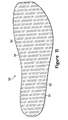
Figure 5 is a top plan view of the chamber. -
Figure 6A-6D are cross-sectional views of the chamber, as defined bysection lines 6A-6D inFigure 5 . -
Figure 7 is a lateral side elevational view of the chamber. -
Figure 8 is a medial side elevational view of the chamber. -
Figure 9 is a bottom plan view of the chamber. -
Figure 10 is a perspective view of a tensile member of the chamber. -
Figure 11 is a top plan view of the tensile member. -
Figure 12 is a lateral side elevational view of the tensile member. -
Figure 13 is a medial side elevational view of the tensile member. -
Figure 14 is a bottom plan view of the tensile member. -
Figure 15 is a perspective view of a mold for forming the chamber. -
Figures 16A-16C are schematic cross-sectional views of the mold, as defined bysection line 16 inFigure 15 , depicting steps in a manufacturing process for the chamber. -
Figure 17 is a perspective view of the chamber and residual portions of polymer sheets forming the chamber following the manufacturing process. -
Figures 18A-18C are top plan views of additional configurations of the chamber. -
Figures 19A-19C are lateral side elevational views corresponding withFigure 8 and depicting additional configurations of the chamber. -
Figures 20A-20D are cross-sectional views corresponding withFigure 6A and depicting additional configurations of the chamber. -
Figure 21 is an elevational view of a ball incorporating a plurality panels with the configurations of fluid-filled chambers. -
Figure 22 is a top plan view of one of the panels. -
Figure 23 is a cross-sectional view of the panel, as defined by section line 23-23 inFigure 22 . - The following discussion and accompanying figures disclose various configurations of fluid-filled chambers and methods for manufacturing the chambers. Although the chambers are disclosed with reference to footwear having a configuration that is suitable for running, concepts associated with the chambers may be applied to a wide range of athletic footwear styles, including basketball shoes, cross-training shoes, football shoes, golf shoes, hiking shoes and boots, ski and snowboarding boots, soccer shoes, tennis shoes, and walking shoes, for example. Concepts associated with the chambers may also be utilized with footwear styles that are generally considered to be non-athletic, including dress shoes, loafers, and sandals. In addition to footwear, the chambers may be incorporated into other types of apparel and athletic equipment, including helmets, gloves, and protective padding for sports such as football and hockey. Similar chambers may also be incorporated into cushions and other compressible structures utilized in household goods and industrial products. Accordingly, chambers incorporating the concepts disclosed herein may be utilized with a variety of products.
- An article of
footwear 10 is depicted inFigures 1 and2 as including an upper 20 and asole structure 30. For reference purposes,footwear 10 may be divided into three general regions: aforefoot region 11, amidfoot region 12, and aheel region 13, as shown inFigures 1 and2 . Footwear 10 also includes alateral side 14 and amedial side 15.Forefoot region 11 generally includes portions offootwear 10 corresponding with the toes and the joints connecting the metatarsals with the phalanges. Midfootregion 12 generally includes portions offootwear 10 corresponding with the arch area of the foot, andheel region 13 corresponds with rear portions of the foot, including the calcaneus bone.Lateral side 14 andmedial side 15 extend through each of regions 11-13 and correspond with opposite sides offootwear 10. Regions 11-13 and sides 14-15 are not intended to demarcate precise areas offootwear 10. Rather, regions 11-13 and sides 14-15 are intended to represent general areas offootwear 10 to aid in the following discussion. In addition tofootwear 10, regions 11-13 and sides 14-15 may also be applied to upper 20,sole structure 30, and individual elements thereof. -
Upper 20 is depicted as having a substantially conventional configuration incorporating a plurality material elements (e.g., textile, foam, leather, and synthetic leather) that are stitched or adhesively bonded together to form an interior void for securely and comfortably receiving a foot. The material elements may be selected and located with respect to upper 20 in order to selectively impart properties of durability, air-permeability, wear-resistance, flexibility, and comfort, for example. Anankle opening 21 inheel region 13 provides access to the interior void. In addition, upper 20 may include alace 22 that is utilized in a conventional manner to modify the dimensions of the interior void, thereby securing the foot within the interior void and facilitating entry and removal of the foot from the interior void.Lace 22 may extend through apertures in upper 20, and a tongue portion of upper 20 may extend between the interior void andlace 22. Given that various aspects of the present application primarily relate tosole structure 30, upper 20 may exhibit the general configuration discussed above or the general configuration of practically any other conventional or nonconventional upper. Accordingly, the overall structure of upper 20 may vary significantly. -
Sole structure 30 is secured to upper 20 and has a configuration that extends between upper 20 and the ground. In effect, therefore,sole structure 30 is located to extend between the foot and the ground. In addition to attenuating ground reaction forces (i.e., providing cushioning for the foot),sole structure 30 may provide traction, impart stability, and limit various foot motions, such as pronation. The primary elements ofsole structure 30 are amidsole 31 and anoutsole 32.Midsole 31 may be formed from a polymer foam material, such as polyurethane or ethylvinylacetate, that encapsulates a fluid-filledchamber 33. In addition to the polymer foam material andchamber 33,midsole 31 may incorporate one or more additional footwear elements that enhance the comfort, performance, or ground reaction force attenuation properties offootwear 10, including plates, moderators, lasting elements, or motion control members.Outsole 32, which may be absent in some configurations offootwear 10, is secured to a lower surface ofmidsole 31 and may be formed from a rubber material that provides a durable and wear-resistant surface for engaging the ground. In addition,outsole 32 may also be textured to enhance the traction (i.e., friction) properties betweenfootwear 10 and the ground.Sole structure 30 may also incorporate an insole or sockliner that is located with in the void in upper 20 and adjacent a plantar (i.e., lower) surface of the foot to enhance the comfort offootwear 10. -
Chamber 33 is depicted individually inFigures 3-9 as having a configuration that is suitable for footwear applications. When incorporated intofootwear 10,chamber 33 has a shape that fits within a perimeter ofmidsole 31 and substantially extends fromforefoot region 11 toheel region 13 and also fromlateral side 14 tomedial side 15, thereby corresponding with a general outline of the foot. Although the polymer foam material ofmidsole 31 is depicted as forming a sidewall ofmidsole 31,chamber 33 may form a portion of the sidewall in some configurations offootwear 10. When the foot is located within upper 20,chamber 33 extends under substantially all of the foot in order to attenuate ground reaction forces that are generated whensole structure 30 is compressed between the foot and the ground during various ambulatory activities, such as running and walking. In other configurations,chamber 33 may extend under only a portion of the foot. - The primary elements of
chamber 33 are abarrier 40 and atensile member 50.Barrier 40 forms an exterior ofchamber 33 and (a) defines an interior void that receives both a pressurized fluid andtensile member 50 and (b) provides a durable sealed barrier for retaining the pressurized fluid withinchamber 33. The polymer material ofbarrier 40 includes anupper barrier portion 41, an oppositelower barrier portion 42, and asidewall barrier portion 43 that extends around a periphery ofchamber 33 and betweenbarrier portions Tensile member 50 is located within the interior void and has a configuration of a spacer-knit textile that includes an uppertensile layer 51, an opposite lowertensile layer 52, and a plurality of connectingmembers 53 that extend betweentensile layers tensile layer 51 is secured to an inner surface ofupper barrier portion 41, lowertensile layer 52 is secured to an inner surface oflower barrier portion 42. Either adhesive bonding or thermobonding, for example, may be utilized to securetensile member 50 tobarrier 40. - In
manufacturing chamber 33, a pair of polymer sheets may be molded and bonded during a thermoforming process to define barrier portions 41-43. More particularly, the thermoforming process (a) imparts shape to one of the polymer sheets in order to formupper barrier portion 41 and an upper area of sidewall portion 43 (b) imparts shape to the other of the polymer sheets in order to formlower barrier portion 42 and a lower area ofsidewall barrier portion 43, and (c) forms aperipheral bond 44 that joins a periphery of the polymer sheets and extends aroundsidewall barrier portion 43. The thermoforming process may also locatetensile member 50 withinchamber 33 and bondtensile member 50 to each ofbarrier portions chamber 33. - Following the thermoforming process, a fluid may be injected into the interior void and pressurized. The pressurized fluid exerts an outward force upon
chamber 33, which tends to separatebarrier portions Tensile member 50, however, is secured to each ofbarrier portions chamber 33 when pressurized. More particularly, connectingmembers 53 extend across the interior void and are placed in tension by the outward force of the pressurized fluid uponbarrier 40, thereby preventingbarrier 40 from expanding outward and retaining the intended shape ofchamber 33. Whereasperipheral bond 44 joins the polymer sheets to form a seal that prevents the fluid from escaping,tensile member 50 preventschamber 33 from expanding outward or otherwise distending due to the pressure of the fluid. That is,tensile member 50 effectively limits the expansion ofchamber 33 to retain an intended shape of surfaces ofbarrier portions -
Chamber 33 is shaped and contoured to provide a structure that is suitable for footwear applications. As noted above,chamber 33 has a shape that fits within a perimeter ofmidsole 31 and extends under substantially all of the foot, thereby corresponding with a general outline of the foot. In addition, surfaces corresponding withbarrier portions Figures 7 and 8 ,chamber 33 exhibits a tapered configuration betweenheel region 13 andforefoot region 11. That is, the portion ofchamber 33 inheel region 13 exhibits a greater overall thickness than the portion ofchamber 33 inforefoot region 11. When incorporated intofootwear 10, the tapering ofchamber 33 ensures that the heel of the foot is slightly raised in relation to the forefoot. In addition to tapering,upper barrier portion 41 is contoured to provide support for the foot. Whereaslower barrier portion 42 has a generally planar configuration betweensides upper barrier portion 41 forms a depression inheel region 13 for receiving the heel of the foot, as depicted inFigures 3 ,6A, and 6B . That is, the heel of the foot may rest within the depression to assist with securing the position of the foot relative tochamber 33. In addition,upper barrier portion 41 has a generally planar configuration inforefoot region 11 for supporting forward portions of the foot, as depicted inFigures 3 ,6A, and 6D . Accordingly,upper barrier portion 41 defines various contours to complement the general anatomical structure of the foot. - The fluid within
chamber 33 may be pressurized between zero and three-hundred-fifty kilopascals (i.e., approximately fifty-one pounds per square inch) or more. In addition to air and nitrogen, the fluid may include octafluorapropane or be any of the gasses disclosed inU.S. Patent Number 4,340,626 to Rudy , such as hexafluoroethane and sulfur hexafluoride. In some configurations,chamber 33 may incorporate a valve or other structure that permits the individual to adjust the pressure of the fluid. - A wide range of polymer materials may be utilized for
chamber 33. In selecting materials forbarrier 40, engineering properties of the material (e.g., tensile strength, stretch properties, fatigue characteristics, dynamic modulus, and loss tangent) as well as the ability of the material to prevent the diffusion of the fluid contained bybarrier 40 may be considered. When formed of thermoplastic urethane, for example,barrier 40 may have a thickness of approximately 1.0 millimeter, but the thickness may range from 0.25 to 2.0 millimeters or more, for example. In addition to thermoplastic urethane, examples of polymer materials that may be suitable forchamber 33 include polyurethane, polyester, polyester polyurethane, and polyether polyurethane.Barrier 40 may also be formed from a material that includes alternating layers of thermoplastic polyurethane and ethylene-vinyl alcohol copolymer, as disclosed inU.S. Patent Numbers 5,713,141 and5,952,065 to Mitchell, et al. A variation upon this material may also be utilized, wherein a center layer is formed of ethylene-vinyl alcohol copolymer, layers adjacent to the center layer are formed of thermoplastic polyurethane, and outer layers are formed of a regrind material of thermoplastic polyurethane and ethylene-vinyl alcohol copolymer. Another suitable material forbarrier 40 is a flexible microlayer membrane that includes alternating layers of a gas barrier material and an elastomeric material, as disclosed inU.S. Patent Numbers 6,082,025 and6,127,026 to Bonk, et al. Additional suitable materials are disclosed inU.S. Patent Numbers 4,183,156 and4,219,945 to Rudy . Further suitable materials include thermoplastic films containing a crystalline material, as disclosed inU.S. Patent Numbers 4,936,029 and5,042,176 to Rudy , and polyurethane including a polyester polyol, as disclosed inU.S. Patent Numbers 6,013,340 ;6,203,868 ; and6,321,465 to Bonk, et al. - In order to facilitate bonding between
tensile member 50 andbarrier 40, polymer supplemental layers may be applied to each oftensile layers barrier portions barrier 40 and the supplemental layers to intermingle or otherwise join with each other. Upon cooling, therefore, the supplemental layer is permanently joined withbarrier 40, thereby joiningtensile member 50 withbarrier 40. In some configurations, thermoplastic threads or strips may be present withintensile layers barrier 40, as disclosed inU.S. Patent Number 7,070,845 to Thomas, et al. , or an adhesive may be utilized to securebarrier 40 andtensile member 50. -
Tensile member 50, which is depicted individually inFigures 10-14 , includes uppertensile layer 51, the opposite lowertensile layer 52, and the plurality of connectingmembers 53 that extend betweentensile layers tensile layers tensile layer 51 is somewhat contoured to impart the tapered configuration and to form a depression inheel region 13. That is, the configuration oftensile member 50 corresponds with the overall configuration discussed above forchamber 33. Connectingmembers 53 are secured to each oftensile layers tensile layers places connecting members 53 in tension and restrains further outward movement oftensile layers barrier portions members 53 are arranged in rows that are separated by gaps. The use of gaps providestensile member 50 with increased compressibility in comparison to tensile members formed of double-walled fabrics that utilize continuous connecting members, although continuous connectingmembers 53 may be utilized in some configurations ofchamber 33. - The lengths of connecting
members 53 vary throughouttensile member 50. As withchamber 33,tensile member 50 has a tapered configuration betweenheel region 13 andforefoot region 11. In order to impart the tapered configuration, the lengths of connectingmembers 53 may decrease betweenheel region 13 andforefoot region 11. As withchamber 33,tensile member 50 also forms a depression inheel region 13. In order to provide the depression, connectingmembers 53 located adjacent tosides heel region 13. Accordingly, by varying the lengths of connectingmembers 53, contours may be imparted totensile member 50. -
Tensile member 50 is formed as a unitary (i.e., one-piece) textile element having the configuration of a spacer-knit textile. A variety of knitting techniques may be utilized to formtensile member 50 and impart a specific configuration (e.g., taper, contour, length, width, thickness) totensile member 50. In general, knitting involves forming courses and wales of intermeshed loops of a yarn or multiple yarns. In production, knitting machines may be programmed to mechanically-manipulate yarns into the configuration oftensile member 50. That is,tensile member 50 may be formed by mechanically-manipulating yarns to form a one-piece textile element that has a particular configuration. The two major categories of knitting techniques are weft-knitting and warp-knitting. Whereas a weft-knit fabric utilizes a single yarn within each course, a warp-knit fabric utilizes a different yarn for every stitch in a course. - Although
tensile member 50 may be formed through a variety of different knitting processes, an advantage of flat-knitting, which is a specific type of weft-knitting, is that generally three-dimensional structures may be produced. In contrast with the "flat" terminology in "flat-knitting", therefore, non-planar, curved, or otherwise generally three-dimensional structures may be produced through flat-knitting. As discussed above,tensile member 50 is a one-piece, spacer-knit textile element that includes uppertensile layer 51, lowertensile layer 52, and connectingmembers 53, which may be formed through flat-knitting. In general, flat-knitting is a method for producing a knitted fabric in which the fabric is turned periodically (i.e., the fabric is knitted from alternating sides). The two sides (otherwise referred to as faces) of the fabric are conventionally designated as the right side (i.e., the side that faces outwards, towards the viewer) and the wrong side (i.e., the side that faces inwards, away from the viewer). Although flat-knitting provides a suitable manner for formingrestriction structure 30, other types of knitting may also be utilized, including wide tube circular knitting, narrow tube circular knit jacquard, single knit circular knit jacquard, double knit circular knit jacquard, warp knit jacquard, and double needle bar raschel knitting, for example. Accordingly, various weft-knitting and warp-knitting techniques may be utilized to manufacturetensile member 50. - Although one or more yarns may be mechanically-manipulated by an individual to form tensile member 50 (i.e.,
tensile member 50 may be formed by hand), flat-knitting machines may provide an efficient manner of forming relatively large numbers oftensile member 50. The flat-knitting machines may also be utilized to vary the dimensions oftensile member 50 to formtensile members 50 that are suitable for individuals with differently-sized feet. Additionally, the flat-knitting machines may be utilized to vary the configuration oftensile member 50 to formtensile members 50 that are suitable for both left and right feet. Accordingly, the use of mechanical flat-knitting machines may provide an efficient manner of forming multipletensile members 50 having different sizes and configurations. Examples of flat-knitting machines that may be utilized to produce various sizes and configurations oftensile members 50 include. - Whereas edges of many textile materials are cut to expose ends of the yarns forming the textile materials,
tensile member 50 may be formed to have a finished configuration. That is, flat-knitting or other knitting techniques may be utilized to formtensile member 50 such that ends of the yarns withintensile member 50 are substantially absent from the edges oftensile layers tensile layers tensile member 50. In addition, loose yarns are also less likely to inhibit the aesthetic appearance of the interior ofchamber 33 In other words, the finished configuration oftensile member 50 may enhance the durability and aesthetic qualities ofchamber 33. - For purposes of the present discussion, the term "yarn" or variants thereof is intended to encompass a variety of generally one-dimensional materials (e.g., filaments, fibers, threads, strings, strands, and combinations thereof) that may be utilized to form a textile. The properties of
tensile member 50 may relate to the specific materials that are utilized in the yarns. Examples of properties that may be relevant in selecting specific yarns fortensile member 50 include tensile strength, tensile modulus, density, flexibility, tenacity, resistance to abrasion, and resistance to degradation (e.g., from water, light, and chemicals). Examples of suitable materials for the yarns include rayon, nylon, polyester, polyacrylic, silk, cotton, carbon, glass, aramids (e.g., para-aramid fibers and meta-aramid fibers), ultra high molecular weight polyethylene, and liquid crystal polymer. Although each of these materials exhibit properties that are suitable fortensile member 50, each of these materials exhibit different combinations of material properties. Accordingly, the properties of yarns formed from each of these materials may be compared in selecting materials for the yarns withintensile member 50. Moreover, factors relating to the combination of yarns and the type of knit or type of textile may be considered in selecting a configuration fortensile member 50. - A further advantage of flat-knitting or other manufacturing techniques for
tensile member 50 relates to the placement of yarns and course density. The type of yarn utilized in different areas oftensile member 50 may change to vary the properties of the different areas. For example, one area oftensile member 50 may stretch more than another area. Similarly, the type of yarn utilized on different sides oftensile member 50 may change to vary the properties of the different sides. Different properties may also be gained by changing the course density in different areas or on different sides oftensile member 50. - Based upon the above discussion,
tensile member 50 incorporates various advantages, including contouring and the finished configuration. The contouring oftensile member 50 may be utilized to impart a variety of shapes to surfaces ofchamber 33. As discussed above,chamber 33 is tapered betweenheel region 13 andforefoot region 11, andchamber 33 has a depression inheel region 13. These contours are imparted tochamber 33 by the configuration oftensile member 50. A variety of other contours (i.e., tapers, depressions, protrusions) may be imparted tochamber 33 by modifying the configuration oftensile member 50. In addition, the finished configuration oftensile member 50 may be utilized to enhance the durability and aesthetic qualities ofchamber 33. Whereas the tensile members of some prior chambers were cut from a larger textile element, thereby exposing ends of the yarns, the knitting technique (e.g., with a flat-knitting machine) utilized to manufacturetensile member 50 may formtensile member 50 as an individual component with a finished configuration. In effect,tensile member 50 may be knitted with a flat-knitting machine to have the general shape ofchamber 33. That is,tensile member 50 may be formed as depicted inFigures 10-14 without the need for additional cutting operations. Although flat-knitting may be utilized to formtensile member 50 to be contoured and have the finished configuration, other knitting techniques may also be utilized. - Although a variety of manufacturing processes may be utilized to form
chamber 33, an example of a suitable thermoforming process will now be discussed. With reference toFigure 15 , amold 60 that may be utilized in the thermoforming process is depicted as including anupper mold portion 61 and alower mold portion 62.Mold 60 is utilized to formchamber 33 from a pair of polymer sheets that are molded and bonded to define surfaces 41-43, and the thermoforming process securestensile member 50 withinbarrier 40. More particularly, mold 60 (a) imparts shape to one of the polymer sheets in order to formupper barrier portion 41 and an upper area of sidewall portion 43 (b) imparts shape to the other of the polymer sheets in order to formlower barrier portion 42 and a lower area ofsidewall barrier portion 43, and (c) forms aperipheral bond 44 that joins a periphery of the polymer sheets and extends aroundsidewall barrier portion 43.Mold 60 also respectively bondstensile layers barrier portions - In
manufacturing chamber 33, one or more of anupper polymer layer 71, alower polymer layer 72, andtensile member 50 are heated to a temperature that facilitates bonding between the components. Depending upon the specific materials utilized fortensile member 50 andpolymer layers barrier 40, suitable temperatures may range from 120 to 200 degrees Celsius (248 to 392 degrees Fahrenheit) or more. As an example, a material having alternating layers of thermoplastic polyurethane and ethylene-vinyl alcohol copolymer may be heated to a temperature in a range of 149 to 188 degrees Celsius (300 and 370 degrees Fahrenheit) to facilitate bonding. Various radiant heaters or other devices may be utilized to heat the components ofchamber 33. In some manufacturing processes,mold 60 may be heated such that contact betweenmold 60 and the components ofchamber 33 raises the temperature of the components to a level that facilitates bonding. - Following heating, the components of
chamber 33 are located betweenmold portions Figure 16A . In order to properly position the components, a shuttle frame or other device may be utilized. Once positioned,mold portions ridge 63 ofupper mold portion 61 contactsupper polymer layer 71, (b) aridge 64 oflower mold portion 62 contactslower polymer layer 72, and (c) polymer layers 71 and 72 begin bending aroundtensile member 50 so as to extend into a cavity withinmold 60, as depicted inFigure 16B . Accordingly, the components are located relative tomold 60 and initial shaping and positioning has occurred. - At the stage depicted in
Figure 16B , air may be partially evacuated from the area aroundpolymer layers mold portions mold 60. This ensures that polymer layers 71 and 72 are properly shaped in accordance with the contours ofmold 60. Note that polymer layers 71 and 72 may stretch in order to extend aroundtensile member 50 and intomold 60. In comparison with the thickness ofbarrier 40 inchamber 33, polymer layers 71 and 72 may exhibit greater thickness. This difference between the original thicknesses of polymer layers 71 and 72 and the resulting thickness ofbarrier 40 may occur as a result of the stretching that occurs during this stage of the thermoforming process. - In order to provide a second means for drawing
polymer layers mold 60, the area between polymer layers 71 and 72 and proximaltensile member 50 may be pressurized. During a preparatory stage of this method, an injection needle may be located between polymer layers 71 and 72, and the injection needle may be located such thatridges mold 60 closes. A gas may then be ejected from the injection needle such that polymer layers 71 and 72 engageridges Figure 17 ) between polymer layers 71 and 72. The gas may then pass throughinflation conduit 73, thereby entering and pressurizing the area proximal totensile member 50. In combination with the vacuum, the internal pressure ensures that polymer layers 71 and 72 contact the various surfaces ofmold 60. - As
mold 60 closes further,ridges upper polymer layer 71 tolower polymer layer 72, as depicted inFigure 16C , thereby formingperipheral bond 44. In addition, amovable insert 65 that is supported byvarious springs 66 may depress to place a specific degree of pressure upon the components, thereby bonding polymer layers 71 and 72 totensile member 50. As discussed above, a supplemental layer or thermoplastic threads may be incorporated intotensile member 50 in order to facilitate bonding betweentensile member 50 andbarrier 40. The pressure exerted upon the components byinsert 65 ensures that the supplemental layer or thermoplastic threads form a bond withpolymer layers ridges tensile member 50 form a bond between other areas of polymer layers 71 and 72 to forminflation conduit 73. - When bonding is complete,
mold 60 is opened andchamber 33 and excess portions of polymer layers 71 and 72 are removed and permitted to cool, as depicted inFigure 17 . A fluid may be injected intochamber 33 through the inflation needle andinflation conduit 73. In addition, a sealing process is utilized to sealinflation conduit 73 adjacent tochamber 33 after pressurization. The excess portions of polymer layers 71 and 72 are then removed, thereby completing the manufacture ofchamber 33. As an alternative, the order of inflation and removal of excess material may be reversed. As a final step in the process,chamber 33 may be tested and then incorporated intomidsole 31 offootwear 10. - Based upon the above discussion,
mold 60 is utilized to (a) impart shape toupper polymer layer 71 in order to formupper barrier portion 41 and an upper area of sidewall portion 43 (b) impart shape tolower polymer layer 72 in order to formlower barrier portion 42 and a lower area ofsidewall barrier portion 43, and (c) formsperipheral bond 44 between polymer layers 71 and 72.Mold 60 also (a) bonds uppertensile layer 51 to the portion ofupper polymer layer 71 that formsupper barrier portion 41 and (b) bonds lowertensile layer 52 to the portion oflower polymer layer 72 that formslower barrier portion 42. - The surfaces of
mold 60 that shapebarrier portions Chamber 33, however, exhibits a tapered configuration betweenheel region 13 andforefoot region 11, andupper barrier portion 41 forms a depression inheel region 13. Whenchamber 33 is pressurized, these contours may arise due to the configuration oftensile member 50. In further manufacturing processes, however,mold 60 may incorporate features (e.g., contours, protrusions, shaping) that correspond with the tapering and depression to facilitate the formation of the tapering and the depression. In addition to the configuration oftensile member 50, the configuration ofmold 60 may also be utilized to impart a specific shape tochamber 33. - A suitable configuration for a fluid-filled
chamber 33 that may be utilized withfootwear 10 is depicted inFigures 3-9 . A variety of other configurations may also be utilized. Referring toFigure 18A ,chamber 33 is depicted as having a configuration that may be utilized inheel region 13. WhereasFigures 3-9 depict a configuration that extends fromheel region 13 to forefootregion 11, some configurations ofchamber 33 may be limited toheel region 13. Similarly,Figure 18B depicts a configuration ofchamber 33 that may be limited toforefoot region 11. In other configurations,chamber 33 may exhibit a lobed structure, as depicted inFigure 18C . -
Chamber 33 is discussed above as being tapered betweenheel region 13 andforefoot region 11. As depicted inFigures 7 and 8 , for example, the taper is relatively smooth such that the thickness ofchamber 33 continually decreases fromheel region 13 to forefootregion 11. As an alternative,chamber 33 may be formed to have planar areas inheel region 13 andforefoot region 11, with a transition inmidfoot region 12, as depicted inFigure 19A . In order to enhance the flexibility ofchamber 33,tensile member 50 may be formed to have relatively thin areas that form depressions in one or both ofbarrier portions chamber 33 is depicted inFigure 19B as having a pair of depressions inforefoot region 11 that enhance the flexibility ofchamber 33 at a location corresponding with toes of the foot. In some further configurations,tensile member 50 may be formed to provide a protrusion inmidfoot region 12 for supporting an arch of the foot, as depicted inFigure 19C . - Although
chamber 33 forms a depression inheel region 13, sides 14 and 15 have substantially identical thicknesses. In some configurations,chamber 33 may taper betweenmedial side 15 andlateral side 14, as depicted inFigure 20A . This taper may, for example, reduce the rate at which the foot pronates during running. Although the depression inheel region 13 is discussed above as being inupper barrier portion 41, the depression may also be inlower barrier portion 42, as depicted inFigure 20B . In further configurations, the depression may be absent fromchamber 33, as depicted inFigure 20C . -
Peripheral bond 44 is depicted as being located betweenupper barrier portion 41 andlower barrier portion 42. That is,peripheral bond 44 is centered betweenbarrier portions peripheral bond 44 may be located on the same plane as either ofbarrier portions peripheral bond 44 is depicted as being level withupper barrier portion 41 inFigure 20D . In this configuration, therefore,upper polymer layer 71 is generally limited to formingupper barrier portion 41, whereaslower polymer layer 72 forms both oflower barrier portion 42 andsidewall barrier portion 43. An advantage of this configuration is that visibility throughsidewall barrier portion 43 is enhanced whensidewall barrier portion 43 is visible on either ofsides footwear 10. -
Chamber 33 is discussed above as having a configuration that is suitable for footwear. In addition to footwear, chambers having similar configurations may be incorporated into other types of apparel and athletic equipment, including helmets, gloves, and protective padding for sports such as football and hockey. Similar chambers may also be incorporated into cushions and other compressible structures utilized in household goods and industrial products. Referring toFigure 21 , aball 80 having the configuration of a soccer ball is depicted as including a plurality of pentagonal andhexagonal panels 81. Each ofpanels 81 have the configuration of a fluid-filled chamber that is similar tochamber 33. More particularly, and with reference toFigures 22 and 23 , one ofpanels 81 is depicted as having abarrier 82 and atensile member 83 located withinbarrier 82. Each ofpanels 81 have curved surfaces that combine to form a generally spherical shape forball 80. In forming each ofpanels 81 and imparting curved contouring topanels 81,tensile member 83 may be knitted or otherwise formed to have a curved configuration, which may have a finished configuration. - The invention is disclosed above and in the accompanying figures with reference to a variety of configurations. The purpose served by the disclosure, however, is to provide an example of the various features and concepts related to the invention, not to limit the scope of the invention. One skilled in the relevant art will recognize that numerous variations and modifications may be made to the configurations described above without departing from the scope of the present invention, as defined by the appended claims.
-
- 1. A fluid-filled chamber comprising:
- an outer barrier formed of a polymer material that defines an interior void;
- a tensile member located within the interior void and bonded to opposite sides of the barrier, the tensile member being formed from a textile element that includes a pair of spaced layers joined by a plurality of connecting members, each of the layers having an edge, at least a portion of one of the edges having a finished configuration; and
- a fluid located within the interior void, the fluid being pressurized to place an outward force upon the barrier and induce tension in at least a portion of the connecting members.
- 2. The chamber recited in clause 1, wherein at least a portion of the layers are non-parallel.
- 3. The chamber recited in clause 1, wherein at least one of the layers is contoured.
- 4. The chamber recited in clause 1, wherein the edges of both of the layers have the finished configuration.
- 5. The chamber recited in clause 1, wherein ends of yarn forming the layers are substantially absent from the edges.
- 6. The chamber recited in clause 1, wherein the chamber is incorporated into an article of footwear.
- 7. An article of footwear having an upper and a sole structure secured to the upper, at least one of the upper and the sole structure incorporating a fluid-filled chamber comprising:
- an outer barrier formed of a polymer material that defines an interior void, the barrier having:
- a first portion that forms a first surface of the bladder,
- a second portion that forms an opposite second surface of the bladder, and
- a sidewall portion that that extends between the first portion and the second portion to form a sidewall of the bladder;
- a tensile member located within the interior void and formed from a plurality of yarns, the tensile member including:
- a first layer joined to the first portion of the barrier, ends of the yarns being substantially absent from an edge of the first layer,
- a second layer spaced from the first layer and joined to the second portion of the barrier, ends of the yarns being substantially absent from an edge of the second layer, and at least a portion of the second layer being non-parallel to the first layer, and
- a plurality of connecting members extending between the first layer and the second layer; and
- a fluid located within the interior volume, the fluid being pressurized to place an outward force upon the barrier and induce tension in at least a portion of the connecting members.
- an outer barrier formed of a polymer material that defines an interior void, the barrier having:
- 8. The article of footwear recited in clause 7, wherein at least one of the first layer and the second layer is contoured.
- 9. The article of footwear recited in clause 7, wherein the chamber is located within the sole structure.
- 10. The article of footwear recited in clause 9, wherein a heel portion of the chamber has a greater thickness than a forefoot portion of the chamber.
- 11. The article of footwear recited in clause 9, wherein a peripheral portion of the chamber has a greater thickness than a central portion of the chamber.
- 12. A method of manufacturing a fluid-filled chamber, the method comprising:
- knitting a tensile member to have a shape of the chamber; and
- locating the tensile member within a polymer barrier and bonding the tensile member to opposite sides of the barrier.
- 13. The method recited in
clause 12, wherein the step of knitting includes dimensioning the tensile member to have a lesser width and a lesser length than the chamber. - 14. The method recited in
clause 12, wherein the step of knitting includes utilizing a flat-knitting machine. - 15. The method recited in
clause 12, wherein the step of knitting includes utilizing yarn, and the step of knitting further includes finishing at least one edge of the tensile member such that ends of the yarn are substantially absent from the edge. - 16. The method recited in
clause 12, wherein the step of knitting includes forming a first area and a second area of the tensile member to have different thicknesses. - 17. The method recited in
clause 12, wherein the step of knitting includes forming a surface of the tensile member to have a contoured configuration. - 18. The method recited in
clause 12, further including a step of incorporating the chamber into an article of footwear. - 19. A method of manufacturing a fluid-filled chamber, the method comprising:
- utilizing a flat-knitting apparatus to form a textile tensile member with at least one contoured surface;
- finishing at least one edge of the tensile member such that ends of yarn within the tensile member are substantially absent from the edge; and
- locating the tensile member within a polymer barrier and bonding the tensile member to opposite sides of the barrier.
- 20. The method recited in clause 19, wherein the step of utilizing the flat-knitting apparatus includes forming the tensile member to have a shape of the chamber and dimensioning the tensile member to have a lesser width and a lesser length than the chamber.
- 21. The method recited in clause 19, further including a step of incorporating the chamber into an article of footwear.
- 22. A method of manufacturing a fluid-filled chamber, the method comprising:
- knitting a tensile member with a first layer, a second layer spaced from the first layer, and a plurality of connecting members with varying lengths extending between the first layer and the second layer;
- finishing edges of the first layer and the second layer such that ends of yarn within the tensile member are substantially absent from the edges;
- locating the tensile member within a polymer barrier and bonding the first layer and the second layer to opposite sides of the barrier; and
- pressurizing the barrier to place the connecting members in tension.
- 23. The method recited in
clause 22, wherein the step of knitting includes forming the tensile member to have a shape of the chamber and dimensioning the tensile member to have a lesser width and a lesser length than the chamber. - 24. The method recited in
clause 22, wherein the step of knitting includes forming a first area and a second area of the tensile member to have different thicknesses. - 25. The method recited in
clause 22, further including a step of incorporating the chamber into an article of footwear.
Claims (15)
- A method of manufacturing a fluid-filled chamber (33) formed from a first polymer barrier portion and a second polymer barrier portion and defining an interior void, the method comprising:knitting a tensile member (50), utilizing yarn, to have a shape of the chamber; andlocating the tensile member within the interior void and bonding the tensile member to the first polymer barrier portion and the second polymer barrier portion, characterized in that:the step of knitting further includes finishing at least one edge of the tensile member such that ends of the yarn are substantially absent from the edge.
- The method of Claim 1, wherein:(1) the step of knitting includes dimensioning the tensile member to have a lesser width and a lesser length than the chamber;(2) the step of knitting includes utilizing a flat-knitting machine;(3) the step of knitting includes forming a first area and a second area of the tensile member to have different thicknesses; and/or(4) the step of knitting includes forming a surface of the tensile member to have a contoured configuration.
- The method of Claim 1, further comprising utilizing a flat-knitting apparatus to form the textile tensile member with at least one contoured surface.
- The method of Claim 3, wherein the step of utilizing the flat-knitting apparatus includes forming the tensile member to have a shape of the chamber and dimensioning the tensile member to have a lesser width and a lesser length than the chamber.
- The method of Claim 1, further including:(1) knitting the tensile member with a first layer (51), a second layer (52) spaced from the first layer, and a plurality of connecting members (53) extending between the first layer and the second layer; and(2) finishing edges of the first layer and the second layer such that ends of yarn within the tensile member are substantially absent from the edges.
- The method of Claim 5, wherein knitting the tensile member with a plurality of connecting members (53) includes knitting the tensile member with a plurality of connecting members with varying lengths.
- The method of Claim 5, wherein knitting the tensile member with a plurality of connecting members (53) includes providing a heel region of the tensile member with connecting members having a greater length than connecting members disposed within a forefoot region of the tensile member.
- The method of any of Claims 5-7, further comprising pressurizing the interior void to place the connecting members in tension.
- The method of any of Claims 5-8, wherein the step of knitting includes forming the tensile member to have a shape of the chamber and dimensioning the tensile member to have a lesser width and a lesser length than the chamber.
- The method of any of Claims 5-9, further comprising attaching one of the first layer (51) and the second layer (52) to one of the first polymer barrier portion and the second polymer barrier portion and attaching the other of the first layer (51) and the second layer (52) to the other of the first polymer barrier portion and the second polymer barrier portion.
- The method of any of Claims 5-10, wherein knitting the tensile member with a first layer (51) and a second layer (52) includes(1) providing the tensile member with at least a portion where the first layer and the second layer are nonparallel and/or(2) providing at least one of the first layer and the second layer with a contoured surface.
- The method of any of the preceding claims, wherein the step of knitting includes forming a first area and a second area of the tensile member to have different thicknesses.
- The method of any of the preceding claims, further comprising pressurizing the interior void.
- The method of any of the preceding claims, further comprising incorporating the chamber into a midsole (31).
- The method of any of the preceding claims, further comprising incorporating the chamber into an article of footwear (10).
Applications Claiming Priority (3)
| Application Number | Priority Date | Filing Date | Title |
|---|---|---|---|
| US12/123,612 US8151486B2 (en) | 2008-05-20 | 2008-05-20 | Fluid-filled chamber with a textile tensile member |
| EP09751229.7A EP2303053B1 (en) | 2008-05-20 | 2009-05-15 | Fluid-filled chamber with a textile tensile member |
| PCT/US2009/044081 WO2009143000A1 (en) | 2008-05-20 | 2009-05-15 | Fluid-filled chamber with a textile tensile member |
Related Parent Applications (2)
| Application Number | Title | Priority Date | Filing Date |
|---|---|---|---|
| EP09751229.7A Division-Into EP2303053B1 (en) | 2008-05-20 | 2009-05-15 | Fluid-filled chamber with a textile tensile member |
| EP09751229.7A Division EP2303053B1 (en) | 2008-05-20 | 2009-05-15 | Fluid-filled chamber with a textile tensile member |
Publications (2)
| Publication Number | Publication Date |
|---|---|
| EP3111793A1 true EP3111793A1 (en) | 2017-01-04 |
| EP3111793B1 EP3111793B1 (en) | 2020-08-05 |
Family
ID=41010253
Family Applications (2)
| Application Number | Title | Priority Date | Filing Date |
|---|---|---|---|
| EP09751229.7A Active EP2303053B1 (en) | 2008-05-20 | 2009-05-15 | Fluid-filled chamber with a textile tensile member |
| EP16173233.4A Active EP3111793B1 (en) | 2008-05-20 | 2009-05-15 | Fluid-filled chamber with a textile tensile member |
Family Applications Before (1)
| Application Number | Title | Priority Date | Filing Date |
|---|---|---|---|
| EP09751229.7A Active EP2303053B1 (en) | 2008-05-20 | 2009-05-15 | Fluid-filled chamber with a textile tensile member |
Country Status (4)
| Country | Link |
|---|---|
| US (1) | US8151486B2 (en) |
| EP (2) | EP2303053B1 (en) |
| CN (1) | CN102123623B (en) |
| WO (1) | WO2009143000A1 (en) |
Families Citing this family (77)
| Publication number | Priority date | Publication date | Assignee | Title |
|---|---|---|---|---|
| GB2455358A (en) * | 2007-12-07 | 2009-06-10 | Siena Black Ltd | Foldable footwear |
| US8210973B2 (en) * | 2008-06-27 | 2012-07-03 | Nike, Inc. | Sport ball bladder |
| US8910319B2 (en) | 2008-12-09 | 2014-12-16 | Dainese S.P.A. | Garment adapted to be associated to a device for the personal protection of a user |
| JP5671472B2 (en) | 2008-12-09 | 2015-02-18 | ダイネーゼ ソシエタ ペル アチオーニ | Body protection devices and clothes incorporating such devices |
| US20100269370A1 (en) * | 2009-04-27 | 2010-10-28 | Valeriy Ivanovich Yefremov | Hollow pneumatic sole sneaker |
| US8095996B2 (en) * | 2009-06-23 | 2012-01-17 | Nike, Inc. | Apparel incorporating a protective element |
| US9675122B2 (en) | 2009-06-23 | 2017-06-13 | Nike, Inc. | Apparel incorporating a protective element |
| US8438669B2 (en) * | 2009-06-23 | 2013-05-14 | Nike, Inc. | Apparel incorporating a protective element |
| US9149084B2 (en) | 2009-06-23 | 2015-10-06 | Nike, Inc. | Apparel incorporating a protective element and method for making |
| US8613149B2 (en) * | 2009-11-10 | 2013-12-24 | Nike, Inc. | Footwear incorporating a composite shell sole structure |
| US9894959B2 (en) | 2009-12-03 | 2018-02-20 | Nike, Inc. | Tethered fluid-filled chamber with multiple tether configurations |
| US9521877B2 (en) | 2013-02-21 | 2016-12-20 | Nike, Inc. | Article of footwear with outsole bonded to cushioning component and method of manufacturing an article of footwear |
| US8479412B2 (en) | 2009-12-03 | 2013-07-09 | Nike, Inc. | Tethered fluid-filled chambers |
| US9801428B2 (en) | 2009-12-03 | 2017-10-31 | Nike, Inc. | Tethered fluid-filled chamber with multiple tether configurations |
| US9750307B2 (en) | 2013-02-21 | 2017-09-05 | Nike, Inc. | Article of footwear having a sole structure including a fluid-filled chamber and an outsole, the sole structure, and methods for manufacturing |
| ITVR20090212A1 (en) * | 2009-12-04 | 2011-06-05 | Dainese Spa | SIZE ADAPTATION DEVICE AND WEARABLE ITEM INCLUDING THIS DEVICE |
| US8381418B2 (en) | 2010-05-10 | 2013-02-26 | Nike, Inc. | Fluid-filled chambers with tether elements |
| US8470113B2 (en) * | 2010-05-12 | 2013-06-25 | Nike, Inc. | Method of manufacturing a contoured fluid-filled chamber with a tensile member |
| US8464439B2 (en) | 2010-05-12 | 2013-06-18 | Nike, Inc. | Contoured fluid-filled chamber with a tensile member |
| US9161592B2 (en) | 2010-11-02 | 2015-10-20 | Nike, Inc. | Fluid-filled chamber with a stacked tensile member |
| US8789294B2 (en) * | 2011-03-16 | 2014-07-29 | Nike, Inc. | Contoured fluid-filled chamber with tensile structures |
| US10010136B2 (en) | 2011-03-16 | 2018-07-03 | Nike, Inc. | Footwear sole structure incorporating a plurality of chambers |
| US9021720B2 (en) * | 2011-03-16 | 2015-05-05 | Nike, Inc. | Fluid-filled chamber with a tensile member |
| US8869430B2 (en) | 2011-03-16 | 2014-10-28 | Nike, Inc. | Method of manufacturing a contoured fluid-filled chamber with tensile structures |
| US8844165B2 (en) | 2011-04-06 | 2014-09-30 | Nike, Inc. | Adjustable bladder system with external valve for an article of footwear |
| US8857076B2 (en) | 2011-04-06 | 2014-10-14 | Nike, Inc. | Article of footwear with an adaptive fluid system |
| US9060564B2 (en) | 2011-04-06 | 2015-06-23 | Nike, Inc. | Adjustable multi-bladder system for an article of footwear |
| US8813389B2 (en) | 2011-04-06 | 2014-08-26 | Nike, Inc. | Adjustable bladder system for an article of footwear |
| US8839530B2 (en) * | 2011-04-12 | 2014-09-23 | Nike, Inc. | Method of lasting an article of footwear with a fluid-filled chamber |
| US8677653B2 (en) | 2011-06-01 | 2014-03-25 | Nike, Inc. | Interchangeable insert system for footwear |
| US9392836B2 (en) | 2011-08-04 | 2016-07-19 | Nike, Inc. | Footwear with interchangeable bootie system |
| US9408436B2 (en) | 2012-01-11 | 2016-08-09 | Nike, Inc. | Heatable and coolable inserts for footwear |
| US20130298317A1 (en) * | 2012-02-09 | 2013-11-14 | Mx Orthopedics, Corp. | Protective padding utilizing superelastic three-dimensional spacer fabric comprising shape memory materials (smm) |
| US20130291399A1 (en) * | 2012-02-09 | 2013-11-07 | Mx Orthopedics, Corp. | Insole and foot orthotics made of shape memory material (smm) three-dimensional spacer fabrics |
| ES2684357T3 (en) | 2012-03-02 | 2018-10-02 | Intex Marketing Ltd. | Inflatable product with internal tension structure |
| US8747593B2 (en) * | 2012-04-10 | 2014-06-10 | Nike, Inc. | Methods for manufacturing fluid-filled chambers incorporating spacer textile materials |
| US9375049B2 (en) | 2012-04-10 | 2016-06-28 | Nike, Inc. | Spacer textile materials and methods for manufacturing the spacer textile materials |
| US9131748B2 (en) | 2012-04-24 | 2015-09-15 | Nike, Inc. | Sole assembly with gas and viscous fluid-filled bladder assembly |
| US10631593B2 (en) | 2012-08-21 | 2020-04-28 | Levi J. Patton | Fluid-filled chamber with a stabilization structure |
| US10058409B2 (en) | 2012-09-18 | 2018-08-28 | Arthrex, Inc. | Spacer fabric mesh for use in tissue engineering applications |
| US9872535B2 (en) * | 2012-12-20 | 2018-01-23 | Nike, Inc. | Article of footwear with a harness and fluid-filled chamber arrangement |
| DE102013207156A1 (en) * | 2013-04-19 | 2014-10-23 | Adidas Ag | Shoe, in particular a sports shoe |
| DE102013207163B4 (en) | 2013-04-19 | 2022-09-22 | Adidas Ag | shoe upper |
| DE102013207155B4 (en) | 2013-04-19 | 2020-04-23 | Adidas Ag | Shoe upper |
| US11666113B2 (en) * | 2013-04-19 | 2023-06-06 | Adidas Ag | Shoe with knitted outer sole |
| US9730487B2 (en) * | 2013-07-12 | 2017-08-15 | Nike, Inc. | Contoured fluid-filled chamber |
| EP3225764B1 (en) | 2013-07-18 | 2020-09-09 | Intex Marketing Ltd. | Inflatable spa |
| CA2822759A1 (en) * | 2013-08-05 | 2015-02-05 | Richard Patrick Desmarais | Footwear having cushioning between sole and upper |
| US9427043B2 (en) * | 2013-10-31 | 2016-08-30 | Nike, Inc. | Fluid-filled chamber with stitched tensile member |
| CN103600502A (en) | 2013-11-25 | 2014-02-26 | 明达实业(厦门)有限公司 | Melting technology of inflatable products |
| DE102014202432B4 (en) | 2014-02-11 | 2017-07-27 | Adidas Ag | Improved football boot |
| US10005231B2 (en) * | 2014-05-23 | 2018-06-26 | Nike, Inc. | Method of manufacturing contoured objects by radio frequency welding and tooling assembly for same |
| DE102014220087B4 (en) | 2014-10-02 | 2016-05-12 | Adidas Ag | Flat knitted shoe top for sports shoes |
| CN107404971B (en) | 2015-03-09 | 2020-12-04 | 耐克创新有限合伙公司 | Article of footwear with outsole bonded to cushioning component and method of making the article of footwear |
| ITVR20150074A1 (en) * | 2015-05-06 | 2016-11-06 | Dainese Spa | PROTECTIVE DEVICE AND METHOD FOR REALIZING THIS PROTECTIVE DEVICE |
| CN108024592B (en) * | 2015-08-27 | 2019-07-16 | 瑞沙德步行鞋有限责任公司 | For the midsole of walking and running, sole assembly and footwear |
| US9907357B2 (en) * | 2015-09-24 | 2018-03-06 | Nike, Inc. | Fluid-filled chamber for an article of footwear |
| WO2017058420A1 (en) | 2015-10-02 | 2017-04-06 | Nike Innovate C.V. | Plate for footwear |
| KR102208854B1 (en) | 2015-10-02 | 2021-01-28 | 나이키 이노베이트 씨.브이. | Plate with foam for footwear |
| US10441027B2 (en) | 2015-10-02 | 2019-10-15 | Nike, Inc. | Footwear plate |
| USD793688S1 (en) * | 2015-12-14 | 2017-08-08 | Nike, Inc. | Shoe outsole |
| USD792066S1 (en) * | 2015-12-18 | 2017-07-18 | Nike, Inc. | Shoe midsole |
| USD793680S1 (en) * | 2015-12-18 | 2017-08-08 | Nike, Inc. | Shoe midsole |
| USD798553S1 (en) * | 2015-12-18 | 2017-10-03 | Nike, Inc. | Shoe midsole |
| ITUA20162315A1 (en) * | 2016-04-05 | 2017-10-05 | Enrico Buziol | POST-OPERATIVE FOOTWEAR |
| US10548368B2 (en) | 2016-07-20 | 2020-02-04 | Nike, Inc. | Footwear plate |
| US11026475B2 (en) | 2016-09-08 | 2021-06-08 | Nike, Inc. | Flexible fluid-filled chamber with tensile member |
| US10524538B2 (en) | 2016-09-08 | 2020-01-07 | Nike, Inc. | Flexible fluid-filled chamber with tensile member |
| USD846851S1 (en) * | 2017-03-03 | 2019-04-30 | Tod's S.P.A. | Sole for footwear |
| IT201700070699A1 (en) * | 2017-06-23 | 2018-12-23 | Dainese Spa | PROTECTION DEVICE |
| US11109637B2 (en) * | 2017-08-31 | 2021-09-07 | Nike, Inc. | Cushioning arrangement for temperature control of a sole structure |
| US11186055B2 (en) * | 2018-03-01 | 2021-11-30 | Nike, Inc. | Method of manufacturing fluid-filled chambers |
| CN110868882B (en) | 2018-04-16 | 2021-09-21 | 耐克创新有限合伙公司 | Shoe outer sole plate |
| US11344078B2 (en) | 2018-04-16 | 2022-05-31 | Nike, Inc. | Outsole plate |
| USD856646S1 (en) * | 2018-05-17 | 2019-08-20 | Nike, Inc. | Shoe |
| EP3975786A1 (en) * | 2019-05-30 | 2022-04-06 | NIKE Innovate C.V. | Sole structure for an article of footwear |
| WO2022147065A1 (en) * | 2020-12-30 | 2022-07-07 | Nike Innovate C.V. | Bladder for a footwear sole structure |
Citations (15)
| Publication number | Priority date | Publication date | Assignee | Title |
|---|---|---|---|---|
| US4183156A (en) | 1977-01-14 | 1980-01-15 | Robert C. Bogert | Insole construction for articles of footwear |
| US4219945A (en) | 1978-06-26 | 1980-09-02 | Robert C. Bogert | Footwear |
| US4340626A (en) | 1978-05-05 | 1982-07-20 | Rudy Marion F | Diffusion pumping apparatus self-inflating device |
| GB2214939A (en) * | 1988-02-19 | 1989-09-13 | Shima Seiki Mfg | Method of preventing the edge of knitted fabric from unravelling |
| US4906502A (en) * | 1988-02-05 | 1990-03-06 | Robert C. Bogert | Pressurizable envelope and method |
| US4936029A (en) | 1989-01-19 | 1990-06-26 | R. C. Bogert | Load carrying cushioning device with improved barrier material for control of diffusion pumping |
| US5042176A (en) | 1989-01-19 | 1991-08-27 | Robert C. Bogert | Load carrying cushioning device with improved barrier material for control of diffusion pumping |
| US5083361A (en) * | 1988-02-05 | 1992-01-28 | Robert C. Bogert | Pressurizable envelope and method |
| US5259207A (en) * | 1989-09-28 | 1993-11-09 | Shima Seiki Mfg., Ltd. | Knitted product |
| US5713141A (en) | 1994-08-31 | 1998-02-03 | Nike, Inc. | Cushioning device with improved flexible barrier membrane |
| US6013340A (en) | 1995-06-07 | 2000-01-11 | Nike, Inc. | Membranes of polyurethane based materials including polyester polyols |
| US6082025A (en) | 1998-09-11 | 2000-07-04 | Nike, Inc. | Flexible membranes |
| US6127026A (en) | 1998-09-11 | 2000-10-03 | Nike, Inc. | Flexible membranes |
| US6321465B1 (en) | 1995-06-07 | 2001-11-27 | Nike, Inc. | Membranes of polyurethane based materials including polyester polyols |
| US20050039346A1 (en) * | 2003-08-18 | 2005-02-24 | Nike, Inc. | Fluid-filled bladder for an article of footwear |
Family Cites Families (32)
| Publication number | Priority date | Publication date | Assignee | Title |
|---|---|---|---|---|
| US3253355A (en) * | 1964-11-20 | 1966-05-31 | Lester L Menken | Cushioned shoe |
| US4025974A (en) * | 1972-01-10 | 1977-05-31 | Lea James M | Air mattress and method of making the same |
| US3984926A (en) * | 1975-11-25 | 1976-10-12 | Samuel Calderon | Heel cushion |
| US4287250A (en) * | 1977-10-20 | 1981-09-01 | Robert C. Bogert | Elastomeric cushioning devices for products and objects |
| US4513449A (en) * | 1983-03-25 | 1985-04-30 | Donzis Byron A | Shock absorbing athletic equipment |
| US4619055A (en) * | 1984-10-29 | 1986-10-28 | Davidson Murray R | Cushioning pad |
| JPS6325004U (en) * | 1986-07-31 | 1988-02-18 | ||
| US4874640A (en) * | 1987-09-21 | 1989-10-17 | Donzis Byron A | Impact absorbing composites and their production |
| MY106949A (en) * | 1988-02-05 | 1995-08-30 | Rudy Marion F | Pressurizable envelope and method |
| US4976352A (en) * | 1988-06-01 | 1990-12-11 | Samsonite Corporation | Camera bag |
| IT1226514B (en) * | 1989-05-24 | 1991-01-24 | Fila Sport | SPORTS FOOTWEAR INCORPORATING, IN THE HEEL, AN ELASTIC INSERT. |
| US5134790A (en) * | 1990-06-22 | 1992-08-04 | Tretorn Ab | Shoe, especially a sport shoe |
| US5572804A (en) * | 1991-09-26 | 1996-11-12 | Retama Technology Corp. | Shoe sole component and shoe sole component construction method |
| EP0605485B2 (en) * | 1991-09-26 | 2005-03-30 | Skydex Technologies, Inc. | Shoe sole component |
| US5802739A (en) * | 1995-06-07 | 1998-09-08 | Nike, Inc. | Complex-contoured tensile bladder and method of making same |
| US5741568A (en) * | 1995-08-18 | 1998-04-21 | Robert C. Bogert | Shock absorbing cushion |
| US5918383A (en) * | 1995-10-16 | 1999-07-06 | Fila U.S.A., Inc. | Sports shoe having an elastic insert |
| US5630237A (en) * | 1996-04-03 | 1997-05-20 | Ku; Tun-Jen | Foam filled inflatable mat with a peripheral air duct |
| DE19616004A1 (en) | 1996-04-18 | 1997-10-23 | Beckmann Wolfgang Dr | Method for connecting several knitted parts on a flat knitting machine |
| IT1292147B1 (en) * | 1997-06-12 | 1999-01-25 | Global Sports Tech Inc | SPORTS FOOTWEAR INCORPORATING A PLURALITY OF INSERTS HAVING DIFFERENT ELASTIC RESPONSES TO FOOT STRESS |
| US6029962A (en) * | 1997-10-24 | 2000-02-29 | Retama Technology Corporation | Shock absorbing component and construction method |
| US5993585A (en) * | 1998-01-09 | 1999-11-30 | Nike, Inc. | Resilient bladder for use in footwear and method of making the bladder |
| US20020121031A1 (en) * | 1998-01-30 | 2002-09-05 | Steven Smith | 2a improvements |
| US6385864B1 (en) * | 2000-03-16 | 2002-05-14 | Nike, Inc. | Footwear bladder with controlled flex tensile member |
| US6665958B2 (en) * | 2001-09-17 | 2003-12-23 | Nike, Inc. | Protective cage for footwear bladder |
| US7131218B2 (en) * | 2004-02-23 | 2006-11-07 | Nike, Inc. | Fluid-filled bladder incorporating a foam tensile member |
| US6837951B2 (en) * | 2001-11-26 | 2005-01-04 | Nike, Inc. | Method of thermoforming a bladder structure |
| US20030097767A1 (en) * | 2001-11-28 | 2003-05-29 | Perkinson Jermaine Derelle | 4-E.V.A system |
| US7076891B2 (en) * | 2003-11-12 | 2006-07-18 | Nike, Inc. | Flexible fluid-filled bladder for an article of footwear |
| US7513066B2 (en) * | 2005-04-14 | 2009-04-07 | Nike, Inc. | Fluid-filled bladder for footwear and other applications |
| US7752772B2 (en) * | 2006-01-24 | 2010-07-13 | Nike, Inc. | Article of footwear having a fluid-filled chamber with flexion zones |
| US7555851B2 (en) * | 2006-01-24 | 2009-07-07 | Nike, Inc. | Article of footwear having a fluid-filled chamber with flexion zones |
-
2008
- 2008-05-20 US US12/123,612 patent/US8151486B2/en active Active
-
2009
- 2009-05-15 CN CN2009801168219A patent/CN102123623B/en active Active
- 2009-05-15 EP EP09751229.7A patent/EP2303053B1/en active Active
- 2009-05-15 WO PCT/US2009/044081 patent/WO2009143000A1/en active Application Filing
- 2009-05-15 EP EP16173233.4A patent/EP3111793B1/en active Active
Patent Citations (19)
| Publication number | Priority date | Publication date | Assignee | Title |
|---|---|---|---|---|
| US4183156A (en) | 1977-01-14 | 1980-01-15 | Robert C. Bogert | Insole construction for articles of footwear |
| US4340626A (en) | 1978-05-05 | 1982-07-20 | Rudy Marion F | Diffusion pumping apparatus self-inflating device |
| US4219945A (en) | 1978-06-26 | 1980-09-02 | Robert C. Bogert | Footwear |
| US4219945B1 (en) | 1978-06-26 | 1993-10-19 | Robert C. Bogert | Footwear |
| US4906502A (en) * | 1988-02-05 | 1990-03-06 | Robert C. Bogert | Pressurizable envelope and method |
| US5083361A (en) * | 1988-02-05 | 1992-01-28 | Robert C. Bogert | Pressurizable envelope and method |
| GB2214939A (en) * | 1988-02-19 | 1989-09-13 | Shima Seiki Mfg | Method of preventing the edge of knitted fabric from unravelling |
| US4936029A (en) | 1989-01-19 | 1990-06-26 | R. C. Bogert | Load carrying cushioning device with improved barrier material for control of diffusion pumping |
| US5042176A (en) | 1989-01-19 | 1991-08-27 | Robert C. Bogert | Load carrying cushioning device with improved barrier material for control of diffusion pumping |
| US5259207A (en) * | 1989-09-28 | 1993-11-09 | Shima Seiki Mfg., Ltd. | Knitted product |
| US5952065A (en) | 1994-08-31 | 1999-09-14 | Nike, Inc. | Cushioning device with improved flexible barrier membrane |
| US5713141A (en) | 1994-08-31 | 1998-02-03 | Nike, Inc. | Cushioning device with improved flexible barrier membrane |
| US6013340A (en) | 1995-06-07 | 2000-01-11 | Nike, Inc. | Membranes of polyurethane based materials including polyester polyols |
| US6203868B1 (en) | 1995-06-07 | 2001-03-20 | Nike, Inc. | Barrier members including a barrier layer employing polyester polyols |
| US6321465B1 (en) | 1995-06-07 | 2001-11-27 | Nike, Inc. | Membranes of polyurethane based materials including polyester polyols |
| US6082025A (en) | 1998-09-11 | 2000-07-04 | Nike, Inc. | Flexible membranes |
| US6127026A (en) | 1998-09-11 | 2000-10-03 | Nike, Inc. | Flexible membranes |
| US20050039346A1 (en) * | 2003-08-18 | 2005-02-24 | Nike, Inc. | Fluid-filled bladder for an article of footwear |
| US7070845B2 (en) | 2003-08-18 | 2006-07-04 | Nike, Inc. | Fluid-filled bladder for an article of footwear |
Also Published As
| Publication number | Publication date |
|---|---|
| US20090288312A1 (en) | 2009-11-26 |
| EP2303053B1 (en) | 2016-07-13 |
| WO2009143000A1 (en) | 2009-11-26 |
| EP2303053A1 (en) | 2011-04-06 |
| EP3111793B1 (en) | 2020-08-05 |
| WO2009143000A8 (en) | 2011-03-03 |
| CN102123623A (en) | 2011-07-13 |
| CN102123623B (en) | 2012-11-07 |
| US8151486B2 (en) | 2012-04-10 |
Similar Documents
| Publication | Publication Date | Title |
|---|---|---|
| EP2303053B1 (en) | Fluid-filled chamber with a textile tensile member | |
| US11259594B2 (en) | Contoured fluid-filled chamber with tensile structures | |
| US11554564B2 (en) | Method of manufacturing a fluid-filled chamber with a tensile element | |
| EP2303054B1 (en) | Contoured fluid-filled chamber with a tensile member | |
| US10959489B2 (en) | Fluid-filled chamber with a tensile member | |
| US8869430B2 (en) | Method of manufacturing a contoured fluid-filled chamber with tensile structures | |
| EP3351127B1 (en) | Article of footwear with fluid-filled chamber with a stacked tensile member |
Legal Events
| Date | Code | Title | Description |
|---|---|---|---|
| PUAI | Public reference made under article 153(3) epc to a published international application that has entered the european phase |
Free format text: ORIGINAL CODE: 0009012 |
|
| STAA | Information on the status of an ep patent application or granted ep patent |
Free format text: STATUS: THE APPLICATION HAS BEEN PUBLISHED |
|
| AC | Divisional application: reference to earlier application |
Ref document number: 2303053 Country of ref document: EP Kind code of ref document: P |
|
| AK | Designated contracting states |
Kind code of ref document: A1 Designated state(s): AT BE BG CH CY CZ DE DK EE ES FI FR GB GR HR HU IE IS IT LI LT LU LV MC MK MT NL NO PL PT RO SE SI SK TR |
|
| STAA | Information on the status of an ep patent application or granted ep patent |
Free format text: STATUS: REQUEST FOR EXAMINATION WAS MADE |
|
| 17P | Request for examination filed |
Effective date: 20170703 |
|
| RBV | Designated contracting states (corrected) |
Designated state(s): AT BE BG CH CY CZ DE DK EE ES FI FR GB GR HR HU IE IS IT LI LT LU LV MC MK MT NL NO PL PT RO SE SI SK TR |
|
| STAA | Information on the status of an ep patent application or granted ep patent |
Free format text: STATUS: EXAMINATION IS IN PROGRESS |
|
| 17Q | First examination report despatched |
Effective date: 20190130 |
|
| GRAP | Despatch of communication of intention to grant a patent |
Free format text: ORIGINAL CODE: EPIDOSNIGR1 |
|
| STAA | Information on the status of an ep patent application or granted ep patent |
Free format text: STATUS: GRANT OF PATENT IS INTENDED |
|
| INTG | Intention to grant announced |
Effective date: 20200226 |
|
| GRAS | Grant fee paid |
Free format text: ORIGINAL CODE: EPIDOSNIGR3 |
|
| GRAA | (expected) grant |
Free format text: ORIGINAL CODE: 0009210 |
|
| STAA | Information on the status of an ep patent application or granted ep patent |
Free format text: STATUS: THE PATENT HAS BEEN GRANTED |
|
| AC | Divisional application: reference to earlier application |
Ref document number: 2303053 Country of ref document: EP Kind code of ref document: P |
|
| AK | Designated contracting states |
Kind code of ref document: B1 Designated state(s): AT BE BG CH CY CZ DE DK EE ES FI FR GB GR HR HU IE IS IT LI LT LU LV MC MK MT NL NO PL PT RO SE SI SK TR |
|
| REG | Reference to a national code |
Ref country code: GB Ref legal event code: FG4D |
|
| REG | Reference to a national code |
Ref country code: CH Ref legal event code: EP |
|
| REG | Reference to a national code |
Ref country code: AT Ref legal event code: REF Ref document number: 1297480 Country of ref document: AT Kind code of ref document: T Effective date: 20200815 |
|
| REG | Reference to a national code |
Ref country code: DE Ref legal event code: R096 Ref document number: 602009062578 Country of ref document: DE |
|
| REG | Reference to a national code |
Ref country code: IE Ref legal event code: FG4D |
|
| REG | Reference to a national code |
Ref country code: LT Ref legal event code: MG4D |
|
| REG | Reference to a national code |
Ref country code: NL Ref legal event code: MP Effective date: 20200805 |
|
| REG | Reference to a national code |
Ref country code: AT Ref legal event code: MK05 Ref document number: 1297480 Country of ref document: AT Kind code of ref document: T Effective date: 20200805 |
|
| PG25 | Lapsed in a contracting state [announced via postgrant information from national office to epo] |
Ref country code: HR Free format text: LAPSE BECAUSE OF FAILURE TO SUBMIT A TRANSLATION OF THE DESCRIPTION OR TO PAY THE FEE WITHIN THE PRESCRIBED TIME-LIMIT Effective date: 20200805 Ref country code: AT Free format text: LAPSE BECAUSE OF FAILURE TO SUBMIT A TRANSLATION OF THE DESCRIPTION OR TO PAY THE FEE WITHIN THE PRESCRIBED TIME-LIMIT Effective date: 20200805 Ref country code: SE Free format text: LAPSE BECAUSE OF FAILURE TO SUBMIT A TRANSLATION OF THE DESCRIPTION OR TO PAY THE FEE WITHIN THE PRESCRIBED TIME-LIMIT Effective date: 20200805 Ref country code: NO Free format text: LAPSE BECAUSE OF FAILURE TO SUBMIT A TRANSLATION OF THE DESCRIPTION OR TO PAY THE FEE WITHIN THE PRESCRIBED TIME-LIMIT Effective date: 20201105 Ref country code: GR Free format text: LAPSE BECAUSE OF FAILURE TO SUBMIT A TRANSLATION OF THE DESCRIPTION OR TO PAY THE FEE WITHIN THE PRESCRIBED TIME-LIMIT Effective date: 20201106 Ref country code: FI Free format text: LAPSE BECAUSE OF FAILURE TO SUBMIT A TRANSLATION OF THE DESCRIPTION OR TO PAY THE FEE WITHIN THE PRESCRIBED TIME-LIMIT Effective date: 20200805 Ref country code: PT Free format text: LAPSE BECAUSE OF FAILURE TO SUBMIT A TRANSLATION OF THE DESCRIPTION OR TO PAY THE FEE WITHIN THE PRESCRIBED TIME-LIMIT Effective date: 20201207 Ref country code: BG Free format text: LAPSE BECAUSE OF FAILURE TO SUBMIT A TRANSLATION OF THE DESCRIPTION OR TO PAY THE FEE WITHIN THE PRESCRIBED TIME-LIMIT Effective date: 20201105 Ref country code: ES Free format text: LAPSE BECAUSE OF FAILURE TO SUBMIT A TRANSLATION OF THE DESCRIPTION OR TO PAY THE FEE WITHIN THE PRESCRIBED TIME-LIMIT Effective date: 20200805 Ref country code: LT Free format text: LAPSE BECAUSE OF FAILURE TO SUBMIT A TRANSLATION OF THE DESCRIPTION OR TO PAY THE FEE WITHIN THE PRESCRIBED TIME-LIMIT Effective date: 20200805 |
|
| PG25 | Lapsed in a contracting state [announced via postgrant information from national office to epo] |
Ref country code: PL Free format text: LAPSE BECAUSE OF FAILURE TO SUBMIT A TRANSLATION OF THE DESCRIPTION OR TO PAY THE FEE WITHIN THE PRESCRIBED TIME-LIMIT Effective date: 20200805 Ref country code: NL Free format text: LAPSE BECAUSE OF FAILURE TO SUBMIT A TRANSLATION OF THE DESCRIPTION OR TO PAY THE FEE WITHIN THE PRESCRIBED TIME-LIMIT Effective date: 20200805 Ref country code: LV Free format text: LAPSE BECAUSE OF FAILURE TO SUBMIT A TRANSLATION OF THE DESCRIPTION OR TO PAY THE FEE WITHIN THE PRESCRIBED TIME-LIMIT Effective date: 20200805 Ref country code: IS Free format text: LAPSE BECAUSE OF FAILURE TO SUBMIT A TRANSLATION OF THE DESCRIPTION OR TO PAY THE FEE WITHIN THE PRESCRIBED TIME-LIMIT Effective date: 20201205 |
|
| PG25 | Lapsed in a contracting state [announced via postgrant information from national office to epo] |
Ref country code: EE Free format text: LAPSE BECAUSE OF FAILURE TO SUBMIT A TRANSLATION OF THE DESCRIPTION OR TO PAY THE FEE WITHIN THE PRESCRIBED TIME-LIMIT Effective date: 20200805 Ref country code: RO Free format text: LAPSE BECAUSE OF FAILURE TO SUBMIT A TRANSLATION OF THE DESCRIPTION OR TO PAY THE FEE WITHIN THE PRESCRIBED TIME-LIMIT Effective date: 20200805 Ref country code: DK Free format text: LAPSE BECAUSE OF FAILURE TO SUBMIT A TRANSLATION OF THE DESCRIPTION OR TO PAY THE FEE WITHIN THE PRESCRIBED TIME-LIMIT Effective date: 20200805 Ref country code: CZ Free format text: LAPSE BECAUSE OF FAILURE TO SUBMIT A TRANSLATION OF THE DESCRIPTION OR TO PAY THE FEE WITHIN THE PRESCRIBED TIME-LIMIT Effective date: 20200805 |
|
| REG | Reference to a national code |
Ref country code: DE Ref legal event code: R097 Ref document number: 602009062578 Country of ref document: DE |
|
| PLBE | No opposition filed within time limit |
Free format text: ORIGINAL CODE: 0009261 |
|
| STAA | Information on the status of an ep patent application or granted ep patent |
Free format text: STATUS: NO OPPOSITION FILED WITHIN TIME LIMIT |
|
| PG25 | Lapsed in a contracting state [announced via postgrant information from national office to epo] |
Ref country code: SK Free format text: LAPSE BECAUSE OF FAILURE TO SUBMIT A TRANSLATION OF THE DESCRIPTION OR TO PAY THE FEE WITHIN THE PRESCRIBED TIME-LIMIT Effective date: 20200805 |
|
| 26N | No opposition filed |
Effective date: 20210507 |
|
| PG25 | Lapsed in a contracting state [announced via postgrant information from national office to epo] |
Ref country code: IT Free format text: LAPSE BECAUSE OF FAILURE TO SUBMIT A TRANSLATION OF THE DESCRIPTION OR TO PAY THE FEE WITHIN THE PRESCRIBED TIME-LIMIT Effective date: 20200805 |
|
| PG25 | Lapsed in a contracting state [announced via postgrant information from national office to epo] |
Ref country code: SI Free format text: LAPSE BECAUSE OF FAILURE TO SUBMIT A TRANSLATION OF THE DESCRIPTION OR TO PAY THE FEE WITHIN THE PRESCRIBED TIME-LIMIT Effective date: 20200805 |
|
| REG | Reference to a national code |
Ref country code: CH Ref legal event code: PL |
|
| PG25 | Lapsed in a contracting state [announced via postgrant information from national office to epo] |
Ref country code: CH Free format text: LAPSE BECAUSE OF NON-PAYMENT OF DUE FEES Effective date: 20210531 Ref country code: LU Free format text: LAPSE BECAUSE OF NON-PAYMENT OF DUE FEES Effective date: 20210515 Ref country code: MC Free format text: LAPSE BECAUSE OF FAILURE TO SUBMIT A TRANSLATION OF THE DESCRIPTION OR TO PAY THE FEE WITHIN THE PRESCRIBED TIME-LIMIT Effective date: 20200805 Ref country code: LI Free format text: LAPSE BECAUSE OF NON-PAYMENT OF DUE FEES Effective date: 20210531 |
|
| REG | Reference to a national code |
Ref country code: BE Ref legal event code: MM Effective date: 20210531 |
|
| PG25 | Lapsed in a contracting state [announced via postgrant information from national office to epo] |
Ref country code: IE Free format text: LAPSE BECAUSE OF NON-PAYMENT OF DUE FEES Effective date: 20210515 |
|
| PG25 | Lapsed in a contracting state [announced via postgrant information from national office to epo] |
Ref country code: BE Free format text: LAPSE BECAUSE OF NON-PAYMENT OF DUE FEES Effective date: 20210531 |
|
| PGFP | Annual fee paid to national office [announced via postgrant information from national office to epo] |
Ref country code: FR Payment date: 20230328 Year of fee payment: 15 |
|
| PG25 | Lapsed in a contracting state [announced via postgrant information from national office to epo] |
Ref country code: HU Free format text: LAPSE BECAUSE OF FAILURE TO SUBMIT A TRANSLATION OF THE DESCRIPTION OR TO PAY THE FEE WITHIN THE PRESCRIBED TIME-LIMIT; INVALID AB INITIO Effective date: 20090515 Ref country code: CY Free format text: LAPSE BECAUSE OF FAILURE TO SUBMIT A TRANSLATION OF THE DESCRIPTION OR TO PAY THE FEE WITHIN THE PRESCRIBED TIME-LIMIT Effective date: 20200805 |
|
| PGFP | Annual fee paid to national office [announced via postgrant information from national office to epo] |
Ref country code: GB Payment date: 20230323 Year of fee payment: 15 |
|
| P01 | Opt-out of the competence of the unified patent court (upc) registered |
Effective date: 20230515 |
|
| PGFP | Annual fee paid to national office [announced via postgrant information from national office to epo] |
Ref country code: DE Payment date: 20230321 Year of fee payment: 15 |