EP3095393A1 - Surgical staple and instrument for holding and implanting the surgical staple - Google Patents
Surgical staple and instrument for holding and implanting the surgical staple Download PDFInfo
- Publication number
- EP3095393A1 EP3095393A1 EP15168542.7A EP15168542A EP3095393A1 EP 3095393 A1 EP3095393 A1 EP 3095393A1 EP 15168542 A EP15168542 A EP 15168542A EP 3095393 A1 EP3095393 A1 EP 3095393A1
- Authority
- EP
- European Patent Office
- Prior art keywords
- bridge
- surgical staple
- staple
- leg
- engagement
- Prior art date
- Legal status (The legal status is an assumption and is not a legal conclusion. Google has not performed a legal analysis and makes no representation as to the accuracy of the status listed.)
- Granted
Links
Images


Classifications
-
- A—HUMAN NECESSITIES
- A61—MEDICAL OR VETERINARY SCIENCE; HYGIENE
- A61B—DIAGNOSIS; SURGERY; IDENTIFICATION
- A61B17/00—Surgical instruments, devices or methods, e.g. tourniquets
- A61B17/56—Surgical instruments or methods for treatment of bones or joints; Devices specially adapted therefor
- A61B17/58—Surgical instruments or methods for treatment of bones or joints; Devices specially adapted therefor for osteosynthesis, e.g. bone plates, screws, setting implements or the like
- A61B17/68—Internal fixation devices, including fasteners and spinal fixators, even if a part thereof projects from the skin
-
- A—HUMAN NECESSITIES
- A61—MEDICAL OR VETERINARY SCIENCE; HYGIENE
- A61B—DIAGNOSIS; SURGERY; IDENTIFICATION
- A61B17/00—Surgical instruments, devices or methods, e.g. tourniquets
- A61B17/064—Surgical staples, i.e. penetrating the tissue
- A61B17/0642—Surgical staples, i.e. penetrating the tissue for bones, e.g. for osteosynthesis or connecting tendon to bone
-
- A—HUMAN NECESSITIES
- A61—MEDICAL OR VETERINARY SCIENCE; HYGIENE
- A61B—DIAGNOSIS; SURGERY; IDENTIFICATION
- A61B17/00—Surgical instruments, devices or methods, e.g. tourniquets
- A61B17/064—Surgical staples, i.e. penetrating the tissue
-
- A—HUMAN NECESSITIES
- A61—MEDICAL OR VETERINARY SCIENCE; HYGIENE
- A61B—DIAGNOSIS; SURGERY; IDENTIFICATION
- A61B17/00—Surgical instruments, devices or methods, e.g. tourniquets
- A61B17/068—Surgical staplers, e.g. containing multiple staples or clamps
- A61B17/0682—Surgical staplers, e.g. containing multiple staples or clamps for applying U-shaped staples or clamps, e.g. without a forming anvil
-
- A—HUMAN NECESSITIES
- A61—MEDICAL OR VETERINARY SCIENCE; HYGIENE
- A61B—DIAGNOSIS; SURGERY; IDENTIFICATION
- A61B17/00—Surgical instruments, devices or methods, e.g. tourniquets
- A61B17/08—Wound clamps or clips, i.e. not or only partly penetrating the tissue ; Devices for bringing together the edges of a wound
- A61B17/083—Clips, e.g. resilient
-
- A—HUMAN NECESSITIES
- A61—MEDICAL OR VETERINARY SCIENCE; HYGIENE
- A61B—DIAGNOSIS; SURGERY; IDENTIFICATION
- A61B17/00—Surgical instruments, devices or methods, e.g. tourniquets
- A61B17/56—Surgical instruments or methods for treatment of bones or joints; Devices specially adapted therefor
- A61B17/58—Surgical instruments or methods for treatment of bones or joints; Devices specially adapted therefor for osteosynthesis, e.g. bone plates, screws, setting implements or the like
- A61B17/68—Internal fixation devices, including fasteners and spinal fixators, even if a part thereof projects from the skin
- A61B17/80—Cortical plates, i.e. bone plates; Instruments for holding or positioning cortical plates, or for compressing bones attached to cortical plates
- A61B17/809—Cortical plates, i.e. bone plates; Instruments for holding or positioning cortical plates, or for compressing bones attached to cortical plates with bone-penetrating elements, e.g. blades or prongs
-
- A—HUMAN NECESSITIES
- A61—MEDICAL OR VETERINARY SCIENCE; HYGIENE
- A61B—DIAGNOSIS; SURGERY; IDENTIFICATION
- A61B17/00—Surgical instruments, devices or methods, e.g. tourniquets
- A61B17/56—Surgical instruments or methods for treatment of bones or joints; Devices specially adapted therefor
- A61B17/58—Surgical instruments or methods for treatment of bones or joints; Devices specially adapted therefor for osteosynthesis, e.g. bone plates, screws, setting implements or the like
- A61B17/68—Internal fixation devices, including fasteners and spinal fixators, even if a part thereof projects from the skin
- A61B17/84—Fasteners therefor or fasteners being internal fixation devices
- A61B17/86—Pins or screws or threaded wires; nuts therefor
- A61B17/8605—Heads, i.e. proximal ends projecting from bone
- A61B17/861—Heads, i.e. proximal ends projecting from bone specially shaped for gripping driver
-
- A—HUMAN NECESSITIES
- A61—MEDICAL OR VETERINARY SCIENCE; HYGIENE
- A61B—DIAGNOSIS; SURGERY; IDENTIFICATION
- A61B17/00—Surgical instruments, devices or methods, e.g. tourniquets
- A61B17/56—Surgical instruments or methods for treatment of bones or joints; Devices specially adapted therefor
- A61B17/58—Surgical instruments or methods for treatment of bones or joints; Devices specially adapted therefor for osteosynthesis, e.g. bone plates, screws, setting implements or the like
- A61B17/68—Internal fixation devices, including fasteners and spinal fixators, even if a part thereof projects from the skin
- A61B17/84—Fasteners therefor or fasteners being internal fixation devices
- A61B17/86—Pins or screws or threaded wires; nuts therefor
- A61B17/8625—Shanks, i.e. parts contacting bone tissue
-
- A—HUMAN NECESSITIES
- A61—MEDICAL OR VETERINARY SCIENCE; HYGIENE
- A61B—DIAGNOSIS; SURGERY; IDENTIFICATION
- A61B17/00—Surgical instruments, devices or methods, e.g. tourniquets
- A61B17/56—Surgical instruments or methods for treatment of bones or joints; Devices specially adapted therefor
- A61B17/58—Surgical instruments or methods for treatment of bones or joints; Devices specially adapted therefor for osteosynthesis, e.g. bone plates, screws, setting implements or the like
- A61B17/68—Internal fixation devices, including fasteners and spinal fixators, even if a part thereof projects from the skin
- A61B17/84—Fasteners therefor or fasteners being internal fixation devices
- A61B17/86—Pins or screws or threaded wires; nuts therefor
- A61B17/866—Material or manufacture
-
- A—HUMAN NECESSITIES
- A61—MEDICAL OR VETERINARY SCIENCE; HYGIENE
- A61B—DIAGNOSIS; SURGERY; IDENTIFICATION
- A61B17/00—Surgical instruments, devices or methods, e.g. tourniquets
- A61B17/56—Surgical instruments or methods for treatment of bones or joints; Devices specially adapted therefor
- A61B17/58—Surgical instruments or methods for treatment of bones or joints; Devices specially adapted therefor for osteosynthesis, e.g. bone plates, screws, setting implements or the like
- A61B17/88—Osteosynthesis instruments; Methods or means for implanting or extracting internal or external fixation devices
- A61B17/92—Impactors or extractors, e.g. for removing intramedullary devices
-
- A—HUMAN NECESSITIES
- A61—MEDICAL OR VETERINARY SCIENCE; HYGIENE
- A61B—DIAGNOSIS; SURGERY; IDENTIFICATION
- A61B17/00—Surgical instruments, devices or methods, e.g. tourniquets
- A61B2017/00526—Methods of manufacturing
- A61B2017/0053—Loading magazines or sutures into applying tools
-
- A—HUMAN NECESSITIES
- A61—MEDICAL OR VETERINARY SCIENCE; HYGIENE
- A61B—DIAGNOSIS; SURGERY; IDENTIFICATION
- A61B17/00—Surgical instruments, devices or methods, e.g. tourniquets
- A61B2017/00831—Material properties
- A61B2017/00858—Material properties high friction, non-slip
-
- A—HUMAN NECESSITIES
- A61—MEDICAL OR VETERINARY SCIENCE; HYGIENE
- A61B—DIAGNOSIS; SURGERY; IDENTIFICATION
- A61B17/00—Surgical instruments, devices or methods, e.g. tourniquets
- A61B2017/00831—Material properties
- A61B2017/00867—Material properties shape memory effect
-
- A—HUMAN NECESSITIES
- A61—MEDICAL OR VETERINARY SCIENCE; HYGIENE
- A61B—DIAGNOSIS; SURGERY; IDENTIFICATION
- A61B17/00—Surgical instruments, devices or methods, e.g. tourniquets
- A61B17/064—Surgical staples, i.e. penetrating the tissue
- A61B2017/0645—Surgical staples, i.e. penetrating the tissue being elastically deformed for insertion
-
- A—HUMAN NECESSITIES
- A61—MEDICAL OR VETERINARY SCIENCE; HYGIENE
- A61B—DIAGNOSIS; SURGERY; IDENTIFICATION
- A61B17/00—Surgical instruments, devices or methods, e.g. tourniquets
- A61B17/56—Surgical instruments or methods for treatment of bones or joints; Devices specially adapted therefor
- A61B2017/564—Methods for bone or joint treatment
-
- A—HUMAN NECESSITIES
- A61—MEDICAL OR VETERINARY SCIENCE; HYGIENE
- A61B—DIAGNOSIS; SURGERY; IDENTIFICATION
- A61B17/00—Surgical instruments, devices or methods, e.g. tourniquets
- A61B17/56—Surgical instruments or methods for treatment of bones or joints; Devices specially adapted therefor
- A61B17/58—Surgical instruments or methods for treatment of bones or joints; Devices specially adapted therefor for osteosynthesis, e.g. bone plates, screws, setting implements or the like
- A61B17/68—Internal fixation devices, including fasteners and spinal fixators, even if a part thereof projects from the skin
- A61B17/84—Fasteners therefor or fasteners being internal fixation devices
- A61B17/86—Pins or screws or threaded wires; nuts therefor
- A61B2017/8655—Pins or screws or threaded wires; nuts therefor with special features for locking in the bone
Definitions
- the present invention relates to a surgical staple as used for compressing bones or bone fragments.
- the invention particularly relates to a surgical staple including a first leg for anchoring in a first bone or bone fragment, at least a second leg for anchoring in a second bone or bone fragment, and a bridge connecting the first leg and the second leg.
- the invention also relates to an instrument for holding and implanting the surgical staple.
- Surgical staples are used to treat angular deformations, fractures particularly with respect to the extremities, subluxation, dislocation, arthritis etc. that may occur with regard to bones of the human body.
- the staples thereby tied to respective bones or bone fragments to fuse these together while exerting a compressive force on these parts. Staples are advantageous over other fusion techniques such as plates in view of the compactness and flexibility.
- Document US 6,908,467 B2 discloses a distraction device made from a nitinol wire which includes an S-curve and bent end regions provided with hooks for anchoring in the bony material.
- a rise of the temperature above the transfer temperature causes the shape memory material to change from a martensite state to an austenite state.
- the device is distracted when the S-curve assumes an elongated shape in the austenite state.
- the hooks self-lock in the opposing bone surfaces and the bone sections distract. Due to the superelastic characteristics of Nitinol, the distraction force remains more constant.
- a bone staple which may be made of Nitinol.
- the staple has a bridge and each one leg extending from corner joints adjacent respective end portions of the bridge.
- the bridge may be slightly arc-shaped whereas the legs extend parallel to each other.
- the bridge also slightly extends beyond the corner joints thereby forming stop means or shoulders.
- the shoulders serve for reinforcing the connection between the legs and the bridge, and, since the level of the shoulder is lower than the bridge, for preventing the bridges from entering into contact with the bone.
- the staple is used to address convexity or concaveness of the vertebral column, wherein the shape memory effect of Nitinol is employed to splay the legs of the staple inserted into respective vertebrae away from each other.
- the staple may be made of a shape memory material such as NiTi and has a connector including a ring of curved portions allowed to be distracted and further including three or four legs arranged parallel to each other.
- a bone staple which has a bridge connecting two legs and which is made from Nitinol.
- the bridge has an S-shape in a plane perpendicular to that of the legs and the legs are inclined toward each other in a closed configuration. In an opened configuration, the legs become parallel.
- Document US 2013/0231667 A1 discloses a surgical staple having a middle section or bridge and side sections or legs which cantilever from ends of the middle section at an angle close to 90°.
- the middle section In a relaxed configuration, the middle section is curved within the plane of the side sections and has an angle of curvature between 15° and 35°.
- the side sections extend towards each other in this configuration.
- Use of Nitinol superelastic material is also disclosed therein.
- a bone staple including a bridge and legs extending from ends of the bridge.
- the bridge has a straight shape in a relaxed as well as in a splayed configuration of the legs.
- the staple is put on a storage block and two tips of respective pivoting inserter handles force the side legs into the splayed configuration at 90° relative to the bridge.
- the staple is made from a super elastic and shape memory material such as Nitinol ASTM 2063.
- the staple may be made of Nitinol and has a bridge and legs extending from ends of the bridge. To achieve a tensioned configuration in which the legs are parallel to each other, the staple is loaded to jaws of the insertion device which may be rotated outwards by means of a spacer configured to separate the jaws, which adversely engage the legs of the staple.
- a surgical staple for compressing bones or bone fragments includes a first leg and a second leg for anchoring in respective bones or bone fragments.
- a bridge connects the first leg and the second leg.
- the bridge has a first end section and a second end section opposite the first end section. The legs extend from the respective end sections.
- the bridge is provided to be arc-shaped, or curved in at least a portion thereof, in a relaxed state of the staple (a state without external forces acting on the staple). This allows to achieve a straight shape with having, e.g., a flat bottom surface when being transferred into an expanded, or opened, state of the staple by means of an instrument.
- the legs In the expanded state of the staple, the legs are generally brought into a configuration being parallel to each other which is suitable for insertion into pre-drilled holes in the bones or bone fragments.
- the bridge may acquire mechanical energy when the staple is expanded and the bridge is bent such as to splay the legs towards, e.g., a parallel configuration.
- the bridge does not only connect the legs but also provides for achieving the expanded state of the legs.
- the bridge may attain a straight shape with its, e.g., flat bottom side section thereby closely following the surface of the bones or bone fragment involved.
- the staple may consume less space within the soft tissue adjacent the bones or below the skin.
- the surgical staple according to one aspect further comprises at least one engagement portion for engagement by an external instrument.
- the engagement portion allows engaging the bridge and maintaining the bridge itself in a bent (expanded) state, the bridge thereby having for example the straight shape.
- the engagement portion may be for example a recess or a projection having a surface facing or at least inclined towards one or both of the first and second legs.
- there are at least two engagement portions provided at the bridge which allows engaging the bridge from two sides.
- the one or more engagement portions are preferably provided to extend at or adjacent the end section(s) of the bridge. This allows to exert a pulling force onto the end sections by means of an instrument with high torque via the engagement portions while exerting a pressing for example the top surface in a centre section of the bridge in an opposite direction with the consequence, that the bridge bends and the legs move away from each other into a parallel configuration.
- the at least one engagement portion may also be located above a plane defined by a bottom surface of the expanded and thus straightly shaped bridge and a direction perpendicular to the legs.
- Such plane may correspond to a bone surface, when the surgical staple is inserted therein.
- the staple may be fully arranged in position in the bones or bone fragments using the external instrument, only. Hence, the number of steps of insertion is also reduced.
- the surgical staple may at least partially be made from a shape memory material, in particular Nitinol.
- the surgical staple is in its first, relaxed state upon fabrication in the austenitic phase.
- the surgical staple is deformed into a desired second shape having parallel legs and a straight bridge for example as explained above. Deformation may be accomplished by a transfer instrument or pliers, for example.
- the deformed surgical staple may be transferred from the transfer instrument or pliers to a staple holder.
- Another option is to use the same plier for deformation from the relaxed shape into the shape for insertion as well as for performing the insertion into the bone(s) itself.
- a so called super- or pseudoelasticity of the shape-memory alloy is utilized. This allows the staple to exert a compression onto the bones involved after insertion and release from the staple holder or plier.
- the (super-)elastic deformation of the staple from its relaxed shape to its shape for insertion involves a phase transformation from austenite to martensite in the highly loaded areas of the staple. These areas remain under a certain stress after insertion of the staple and enable the staple to exert a force onto the bones and to compress them.
- the staple holder includes a face formed with a cavity shaped to receive the bridge of the surgical staple in an expanded state thereof, wherein the cavity is provided with at least one engagement structure complementary to and cooperating with the respective at least one engagement portion provided at the bridge of the staple.
- the cavity thereby provides at least some of the reverse surface features of the bridge including the engagement portions. As the cavity is adjacent to the face and opens thereto, the bridge may safely be received in the cavity with the legs and the bottom side section of the bridge being exposed to the outside and ready for insertion to the bones.
- an expansion device includes a transfer portion provided on a boss which allows displacing the surgical staple from a first portion of the boss where it is received in its relaxed state to a second portion where it is expanded.
- the expansion may relate to an elastic deformation or a plastic deformation.
- An accommodation space which accommodates the staple holder is then structured such as to allow the bridge when reaching the second portion to be received in the cavity of the staple holder.
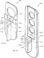
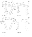
- FIG. 1a A first embodiment of a surgical staple 1, which can be used for example with embodiments of an expansion device 1002 and a staple holder 1090 shown in Figs. 2a through 4 , respectively, is explained with reference to Figs. 1a - 1d.
- Figs. 1a and 1c reveals details of the surgical staple 1 in a relaxed state in perspective and front views, respectively.
- a relaxed state is defined herein as a state in which no external forces act on the staple.
- this state further refers an austenite phase state, wherein the shape attained in this state is related to the shape memorized upon fabrication.
- the surgical staple comprises a bridge 2, a first leg 3 and a second leg 4 both connected to the bridge 2 at respective end sections 29, 29'.
- the bridge 2 includes an elongate body extending between and including end sections 29, 29'.
- the bridge 2 in this embodiment has a rectangular cross section thereby forming a top surface 21, front and back side surfaces 22, 23 and bottom surface 24.
- the bridge 2 In the relaxed state shown in Figs. 1a and 1c , the bridge 2 is arc-shaped or curved.
- the curvature, or radius of curvature is constant in the embodiments shown but may also vary along the length of the bridge, or may be present only in portions thereof (an example thereof will be explained with reference to Figs. 18a-18d below).
- the legs 3 and 4 extend from the end sections 29, 29' including an angle ⁇ of about 90° with respect to the bridge at the location of the connection, respectively, as can be seen in Fig. 1c .
- the bottom surface 24 of the arc-shaped bridge 2 forms a curved plane 81' in the relaxed state and the angle ⁇ may for example be measured at an intersection of a line or plane 80 extending along lateral surfaces 30, 40 of legs 3, 4, respectively, and curved plane 81' as illustrated in Fig. 1c .
- angles ⁇ do not (substantially) vary when the staple changes from the relaxed to the expanded state.
- the end sections 29, 29' of the bridge 2 include extension portions 5, 5' which extend beyond the location of connection between the bridge 2 and the legs 3, 4, respectively.
- the extension portions 5, 5' are both tapered towards respective rounded tips, thereby forming slightly inclined surfaces which may be engaged by corresponding engagement structures of an external tool in order to expand, or maintain an expansion of, the surgical staple 1 as will be described below.
- the extensions 5, 5' each form engagement portions 51, 52 according to the invention, which may be received for example in a form-fit manner by an external instrument or tool.
- the legs 3 and 4 of the surgical staple 1 have outer lateral side surfaces 30 and 40, inner side surfaces 70 and front/back side surfaces 31 and 41, respectively, and also include a rectangular cross section.
- a number of barbs 7 is formed which comprise a slightly inclined wall 71 and a perpendicularly protruding wall 72 which forms a sharp edge.
- the barbs 7 are directed upwardly and serve to improve anchoring in the bone.
- An upper portion of the legs 3, 4 adjacent the bottom surface 24 of the bridge 2 may be left free of barbs 7.
- three barbs 7 are formed at the inner surfaces 70 of the legs 3 and 4, but more or less or even no barbs may be formed in other embodiments.
- each of the legs 3, 4 has a tip 6, 6', respectively.
- tips 6, 6' are flat surfaces which have the overall square-like cross section of the legs.
- the tips 6, 6' are tapered and/or sharp and/or rounded and/or conical shaped as known in the art in order to improve the insertion process of the legs into the bones. This pertains also to the other embodiments described below.
- the legs 3 and 4 extend substantially perpendicularly from the bridge 2 as noted above. As the bridge 2 is arc-shaped in the relaxed state, the legs 3 and 4 consequently extend towards each other. In this specific embodiment, lines or planes 80, 80' extending along the outer lateral side walls 30, 40 of the legs, 3, 4, respectively, intersect each other at about 30° in the relaxed state. However, other intersection angles ⁇ between 25° and 35° or between 20° and 40° or even beyond these values are encompassed as well.
- Figs. 1b and 1d show an expanded state of the surgical staple 1 of the first embodiment.
- the legs 3 and 4 are laterally moved away from each other such as to be arranged in parallel with respect to each other.
- the expansion from the relaxed state is accomplished by applying mechanical energy to the bridge 2 via engaging portions 51, 52, wherein the bridge 2 may be bent like a spring, when conventional materials such as stainless steel is considered for the staple.
- a shape memory material such as Nitinol is considered for the surgical staple.
- the range of deformation can be extended due to the superelasticity of this material.
- the expansion may also relate to an elastic deformation of the staple in the martensitic phase by cooling the staple before expansion.
- the staple then exerts its full compression onto the bones after insertion when the staple is again at a higher temperature (body temperature).
- the angles ⁇ are maintained during the expansion of the surgical staple 1 at 90° with respect to both legs 3 and 4.
- the bridge 2 attains a straight shape, and its bottom surface 24 becomes substantially flat, i.e., almost not curved.
- the bottom surface 24 thus defines a straight plane 81 perpendicular to a plane defined by the bridge 2 and the legs 3 and 4.
- the inclined surfaces of the engagement portions 51 and 52 remain being arranged above the plane 81 defined by the bottom surface 24 of the bridge 2 and directions perpendicular to legs 3, 4, or axis 80, respectively, which may be associated with the bone surface, when the staple is implanted to the bone(s).
- the surgical staple 1 is attached to bones with the legs 3 and 4 being for example inserted into holes drilled in advance into respective bones or bone fragments, the insertion process may be made until the bottom surface 24 of the bridge abuts on the plain bone surface, since the engagement portions 51 and 52 may advantageously be engaged or disengaged above that surface.
- FIG. 2a An embodiment of a device 1002 for expanding the surgical staple 1 is displayed in Fig. 2a .
- the expansion device 1002 is non-limiting and other devices may be used to effect expansion of the surgical staple 1.
- the expansion device 1002 shown has a substantially plate-shaped body 1001 from which protrudes a boss 1020, which is removably connected to the body 1001 and is arranged to receive the surgical staple 1 in a relaxed state 1101 (see Fig. 4 ) at a first portion 1023 adjacent the free end of the boss 1020.
- An upper surface 1021 of the boss 1020 is designed to contact the bridge 2, and more specifically: the bottom surface 24 thereof.
- the upper surface 1021 has a curvature corresponding to the arc-shape of the bottom surface 24 or the curved plane 81' as shown in Fig. 1b .
- the legs 3 and 4 extending towards each other in the relaxed state are received in recesses 1022 formed in the boss 1020 on lateral faces thereof below the upper surface 1021.
- the boss 1020 also has a second portion 1024 adjacent the plate-shaped body 1001 from which the boss 1020 extends.
- the upper surface is almost flat corresponding the flatness of plane 81 of the bottom surface 24 in an expanded state 1102 of the surgical staple 1 as shown in the enlarged view of Fig. 4 .
- the depth of recesses 1022 for receiving the legs 3, 4 is decreased.
- transfer portion 1025 In which the profile of the upper surface 1021 smoothly changes from curved to flat, and the depth of the recesses 1022 smoothly varies from deep to shallow.
- transfer portion 1025 allows continuous expansion of the staple 1 by (a) attaching the staple to the boss 1020 at the first portion 1023, (b) displacing the staple 1 along the transfer portion 1025, and (c) disposing the staple 1 at the second portion 1024 adjacent the plate-shaped body 1001.
- the plate-shaped body 1001 is provided with guide walls 1004 and an abutment wall 1005 which form an accommodation space 1003 for accommodating a staple holder 1090, which is shown in Figs. 3a and 3b .
- the staple holder 1090 has a flat, substantially rectangular plate-shaped body 1099 with opposite flat faces 1091 and narrow side faces 1095, 1096 and narrow front faces 1094. Narrow side faces 1095, 1096 involve a recess 1092 configured to allow safe manual handling of staple holder.
- the narrow front faces 1094 respectively include apertures 1086 allowing access to cavities 1096 formed adjacent to the front faces 1094.
- the cavities 1094 are configured (i.e., shaped, sized and dimensioned) to receive the bridge 2 of a respective staple 1 as that shown with respect to the first embodiment.
- the cavities 1096 are formed with engagement structures 1081, respectively, which are provided at corresponding ends of a cavity 1091 associated with the locations of the engagement portions 51, 52 of the bridge 2 when received therein.
- the engagement structures 1081 are in this embodiment small projections (narrowing aperture 1086 with respect to cavity 1096) inserted below the engagement portions 51, 52 of the bridge 2, when the staple is displaced into the second portion of the boss 920, and hence allow to engage the engagement portions 51 and 52 and thus to maintain the expanded state 1102 of the surgical staple 1 when received in one of the cavities 1096, as it is depicted in Fig. 4 .
- a counterforce is necessarily exerted onto the top surface 21 of the bridge 2 particularly in a centre portion thereof, and may for example be provided by an inner back wall opposite the aperture 1086 of the cavity, which back wall herein serves as a pressing portion 1084.
- the accommodation space 1003 provided by guide and abutment walls 1004 and 1005 allows accommodating the staple holder 1090 such that a second aperture 1083 formed in one of the flat faces 1091 adjacent the front faces 1094 allows inserting the bridge 2 when travelling into the second portion 1024 of the boss 1020.
- the bridge coincidently abuts on a side wall 1085 opposite the aperture 1083 of the cavity 1096.
- the boss 1020 can be removed from the body 1001, and the staple holder 1090 may be removed from the expansion device 1001 with the surgical staple 1 held in the expanded state by virtue of engagement structures 1081 and engagement portion 51, 52, respectively, and further by virtue of a pressing force exerted by pressing portion 1084 urging into a direction opposite to the pulling force of the engagement structures.
- the surgical staple 1 may be attached to a bone or bone assembly with holes pre-drilled therein (not shown in this embodiment). Since the legs 3, 4 are held by the staple holder 1090 in parallel, manual insertion is facilitated until the bridge 2 abuts on the bone surface.
- the staple holder 1090 may release the bridge by a lateral movement, wherein the bridge 2 already adhering to the bone surface leaves the cavity 1096 through the lateral second aperture 1083. As a consequence, the bridge 2 is released, which thus tries to return into its original curved shape in view of the mechanical energy stored therein, whereby a compression force is exerted on the legs 3, 4, which adversely compress the bones or bone fragments involved via the pre-drilled holes in which the legs are inserted.
- a further advantage of this and also the other embodiments described herein arises in that since the mechanical energy is stored in the initially arc-shaped or curved bridge 2 which is then made to have a straight shape, a distribution of the compression force (of the legs 3, 4 towards each other) along the legs 3, 4 is distributed in a broadened manner and thus improved, and may have a maximum in a region including the first and second barbs 7 when counted from the side of the bridge 2. Moreover, the compression forces are distributed farther away from the bridge 2, i.e., act upon the inner walls 1352 of the holes 1351, which are formed in the bone 1350 when the staple 1 is inserted therein, at a deeper position. Hence, the reliability of the anchoring is also considerably improved.
- FIG. 26 An impression of the distribution of compression forces exerted by the leg 3 of the surgical staple 1 is provided in Fig. 26 as an example.
- the surgical staple is placed in a pre-drilled hole 1351 formed in a bone 1350.
- the arrows indicate the amount of force exerted by a respective portion of the leg 3 at a given height level, the force being oriented in a direction parallel to the bridge 2 and perpendicular to the legs 3, 4, when the surgical staple 1 is in the expanded state, or is still expanded and just released to exert the forces onto the inner wall 1352 of the hole 1350.
- a maximum compression force is exerted at about a height level of the first barb 7a, or between the first barb 7a and the second barb 7b, while a smooth distribution of forces up the tip 6, 6' of the leg 3 is achieved.
- a smooth maximum is achieved in a middle third or even in a bottom third along the length of a leg.
- a more sharp peak is generally measured at a height level of a leg closer to an upper surface of the bone, or closer to the bridge, i.e. in an upper third.
- stress and strain may particularly be reduced at one of the most critical point of the staple, the inner corner at the junction, or location of connection, between the legs 3, 4 and the bridge 2. This may further improve the reliability of the staple.
- One particular advantage of the first (and second) embodiment of the surgical staple is that due to the engagement portions formed as projections at the end section 29, 29' beyond the junction, namely by means of extensions 5, 5', the moment of torque for bending the bridge is considerably increased as compared to a case where for example the bottom surface 24 of the bridge is engaged adjacent the connection with the legs 3, 4. This in turn relaxes the requirements for the external instrument to maintain the expanded state of the staple 1, 101.
- the staple holder 1090 along with the expansion device 1002 forms a first embodiment of an instrument.
- a second embodiment of an instrument which can be used in conjunction with staples 1, 101 and 901 of the first, second and tenth embodiment (described below) of a surgical staple.
- the expansion device is represented by a plier 1202, while the staple holder 1090 of the first embodiment (instrument) can be used herein as well to receive and hold the staple 1, 101.
- walls 1092 and 1085 are omitted for simplicity.
- the plier 1202 includes two handles 1204, 1206 rotatably coupled via shaft 1209. Each handle 1204, 1206 has a tip portion 1205, 1207, respectively. As shown in more detail in Fig.
- the tip portions 1205, 1207 are correspondingly closed such that legs 3, 4 of the staple may be received on an outer side thereof.
- the tip portions 1205, 12ß7 move away from each other such as to splay the legs 3, 4 of the surgical staple 1 as shown in Fig. 7b .
- the plier may be arranged with respect to the staple holder 1090 such that the bridge 2 is inserted into the cavity 1096 through the lateral aperture 1083 with the legs protruding from the cavity 1096 through a frontal aperture 1086 of the staple holder 1090.
- the plier 1202 manually held until this step under tension, may then be released.
- the engaging portions 51, 52 of the surgical staple are forcibly engaged by the engaging structures 1081 of the staple holder 1090 and a pressing force is exerted by the pressing portion 1084 of the back wall of the cavity 1096.
- the plier may then be removed, and the surgical staple placed in a bone as explained above using the staple holder 1090.
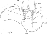
- FIG. 8a - 8h A third embodiment of an instrument and a method of using the same according to the invention is described with reference to Figs. 8a - 8h .
- the tasks of expanding and holding the staple are performed by one single device different from the instrument according to the first and second embodiments.
- Fig. 8a shows a step of providing the surgical staple 1.
- Staples 101 or 901 provided with extensions 5, 5' as engagement portions 51, 52, 151, 152, 951, 952 are compatible with this instrument as well.
- Fig. 8b shows a second step of engaging the surgical staple 1 by means of plier instrument 1302, i.e., the bridge 2 including the engaging portions 51, 52 of staple 1 is received between the engagement structures 1381 provided at the tips of handles or arms 1304, 1306.
- Plier instrument 1302 has two such handles or arms 1304, 1306, which have interfaces 1305, 1307, respectively, for connecting further plier mechanics (not shown) allowing to suitably actuate the arms 1304, 1306 by for example manual input.
- Such mechanics are well-known in the field of pliers and serve to provide a cooperating movement of the arms.
- Fig. 8c shows a third step of the method, wherein the surgical staple 1 is expanded by closing the arms 1304, 1306 of the plier instrument 1302 thereby pulling the engaging portions 51, 52 upwards and pressing a centre portion of the top surface 21 downwards by means of the pressing portion 1382 also provided at the tip portion of the arms 1304, 1306, respectively.
- a cavity is dynamically formed by means of engagement structures 1381 and pressing portions 1382 which holds the bridge 2 in a bent and staple 1 in an expanded state.
- Fig. 8d illustrates a fourth step of applying the expanded surgical staple 1 to the situation of a hallux valgus.
- an AKIN procedure involving a surgical correction of a misalignment of the os metatarsalis is performed via osteotomy.
- the surgical staple 1 is applied to holes 1353, 1354 previously drilled into the fragments of the bone 1350 (in this example: os metatarsalis).
- the legs 3, 4 of the staple are aligned with such holes 1353, 1354, respectively, using the plier instrument 1302.
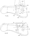
- Fig. 8e shows a fifth step of the method wherein the legs 3, 4 are fully inserted into the holes 1353, 1354 using the plier instrument 1302.
- the bottom surface 24 of the bridge 2 has engaged the bone surface, while the engagement structures 1381 are still in forcible engagement with the bridge 2.
- Fig. 8f shows a perspective view of the situation depicted in Fig. 8e , wherein the legs 3, 4 are residing in the holes 1353, 1354 parallel to each other in the expanded state held by the plier instrument 1302.
- Fig. 8g shows a side view of the situation depicted in Fig. 8f .
- the legs 3, 4 have not yet engaged the side walls of the holes 1353, 1354 and the staple is thus not yet anchored in the bone 1350.
- Fig. 8h shows a sixth step of the method of using the plier instrument 1302.
- the bridge 2 has now been released by the plier instrument 1302, which is now removed. No direct forces act on the bridge 2 any more. Hence, the bridge 2 starts to release the mechanical energy stored thereby tending to return back into the arc-shape.
- the legs 3, 4 moving towards each other abut on mutually opposite side wall surfaces of the holes 1353, 1354 thereby compressing the two bone fragments of bone 1350. As the barbs 7 bite or dig into the bony side wall surfaces of holes 1353, 1354, anchoring is also accomplished thereby.
- the second embodiment of a staple differs from the first embodiment in that the legs 103, 104 extend from the bridge 2 at angles ⁇ and ⁇ , respectively, which are different from 90°. More specifically, both legs 103, 104 do not extend from end sections 29, 29' of the bridge 2 perpendicularly, but at an oblique angle. Both angles differ from 90° by about 15°. The inclination is made to be oriented towards the same direction (in Figs. 9a - 9d , towards the left side direction). As a consequence, as can be seen in Figs. 9b and 9d , in the expanded state, both legs are inclined with respect to the bridge 2 thereby extending in parallel to each other.
- the embodiment becomes particularly advantageous in clinical situations where an inclined insertion is necessary.
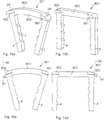
- a third embodiment of a surgical staple 301 is depicted in Figs. 10a - 10d .
- a bridge 302 is provided which has a top surface 321, a front side wall surface 322, a back side wall surface 323 and a bottom surface 324 (the terms "front” and “back” simply make reference to the drawings herein, of course the staple may be reversed).
- the bridge 302 of surgical staple 301 is arc-shaped or curved in the relaxed state as shown in Figs. 10a and 10c , and is straight or plane-shaped in the expanded state as shown in the Figs. 10b and 10d .
- the legs 3, 4 are similar to the first embodiment, wherein upper ends adjacent the bridge 302 are slightly reinforced by inclined outer surfaces 331.
- protrusions flush with the top surface 321, which extends along the back and front wall surface from the first end section 29 up to the second end section 29'.
- the protrusions represent engagement portions 351, 352 which each form an overhang at the back and front wall side surfaces 322, 323 with a surface at its bottom, which is oriented towards the legs 3, 4 and which serves to receive a pulling force from engagement structures of an external instrument (not shown).
- the bridge 302 thus has, when seen in cross section, a T-shape along almost its entire length.
- the engagement portions 351, 352 may be engaged by an engagement structure of an external instrument (not shown) to hold the surgical staple 301 in an expanded state.
- the protrusions of the engagement portion 351, 352 extend up to the end sections 29, 29' such that the necessary moments of torque to maintain the expanded state of the surgical staple 301 can be afforded by the external instrument.
- the staple holder 1090 of Figs. 3a, 3b may be modified to include a cavity having engagement structures complementary in shape to the instant protrusions.
- the engagement portion 351, 352 are located above a plane 81 in the expanded state which allows removal of the external instrument even in the fully installed state in the bone.
- engagement portions 351, 351 extend from one end section 29 to the other end section 29' along the side wall surfaces 322, 323, engagement by engagement structures of an external instrument may occur only in parts thereof, preferably at or adjacent the end section 29, 29', as indicated above.
- engagement portions 651, 652 may also be provided to extend along the side wall surfaces 622, 623 only within end sections 29, 29'.
- the T-shape of the bridge 602 is also provided only in the end sections 29, 29' of the bridge 602.
- FIG. 12a shows the step of providing the surgical staple 601
- Fig. 12b indicates the instrument 1406 attached to the staple 601.
- the instrument 1402 may be, for example a plier instrument or spreading pliers or another device. It may have a similar structure of arms or handles 1404, 1406 as that shown with respect to the plier instrument 1302 of Figs. 8a - 8h (third embodiment of an instrument).
- the arms or handles 1404, 1406 have engagement structures 1481 extending from tip portions of the arms and engage around the projections of the engagement portions 651, 652 of the bridge 602 from a centre direction of the bridge 602 in a direction outwards away from each other.
- the handles or arms 1404, 1406 are then closed at an end opposite the tip portions in a third step such that the tip portions itself perform a rotational movement, as it is shown in Fig. 12c , thereby lifting or pulling the engagement portions 651, 652 by virtue of the engagement structures 1481.
- flat pressing portions 1482 also provided at the tip portions of the arms or handles 1404, 1406 press onto the top surface 621 of the bridge, which results in an expansion of the staple.
- the further steps may be the same as explained with regard to Fig. 8d - 8h .
- a fifth embodiment of a surgical staple 701 is shown in Figs. 13a - 13d .
- the surgical staple 701 differs from the staples 301 and 601 in that one (front) side wall surface 722 of the bridge 702 has two projections corresponding to engagement portions 751, 752 provided only at the end sections 29, 29', while the other (back) side wall surface 723 has one projection corresponding to engagement portion 753 fully extending from one end section 29 to the other end section 29'.
- FIG. 14a -14d A sixth embodiment of a surgical staple is depicted in Figs. 14a -14d .
- a bridge 202 is provided which has a top surface 221, a front wall surface 222, a back side wall surface 223 and a bottom surface 224 (the terms “front” and “back” simply make reference to the drawings herein, of course the staple may be reversed).
- the bridge 202 of surgical staple 201 is arc-shaped or curved in the relaxed state as shown in Figs. 14a and 14c , and is straight or plane-shaped in the expanded state as shown in the Figs. 14b and 14d .
- the legs 3, 4 are similar to the first embodiment, wherein upper ends adjacent the bridge 202 are slightly reinforced by inclined outer surfaces 331.
- the protrusion 253 forms an engagement portion 251 which may be engaged by an engagement structure of an external instrument (not shown) to hold the surgical staple 201 in an expanded state.
- the cross section of the bridge 202 according to this embodiment is L-shaped.
- the advantages and effects achieved by the sixth embodiment are also similar to that of the third to fifth embodiments.
- the surfaces of engagement portions 251 are oriented to, or face, the legs 3,4, and are located above a plane 81 defined by the bottom surface 224 of the bridge 202.
- Legs 3, 4 also include a reinforcement with regard to inclined outer surface 231.
- a seventh embodiment of a surgical staple 801 is shown with regard to Figs. 15a - 15d .
- the surgical staple 801 is a simple modification of that shown in the sixth embodiment, wherein, however, the projection extends only in the end sections 29, 29' to yield single-sided engagement portions 851, 852 extending along the side wall surface 822 only in a limited region.
- FIG. 16a - 16b shows a surgical staple 401 only in an expanded state.
- a relaxed state (not shown) is analogous to the previous embodiments.
- This embodiment is similar to the third embodiment in that two continuous protrusions are formed at both of the side wall surfaces 422, 423 of the bridge 402, and are flush with the top surface 421.
- the protrusions include slightly oblique surfaces, which are only slightly inclined towards the legs 3, 4. These oblique surfaces extend along the bridge 402 from a first end section 29 up the second end section 29' and are located above the plane 81 defined by the bottom surface 424 of the bridge 402.
- the protrusions and oblique surfaces represent engagement portions 451, 452 according to the invention and may be engaged by corresponding engagement structures of an external instrument (not shown) such as to maintain the expanded state prior and during implantation.
- FIG. 17a - 17b shows a surgical staple 501 also only in an expanded state.
- a relaxed state (not shown) is analogous to the previous embodiments.
- the side wall surfaces 522 and 523 of the bridge 502 include recesses extending from the first end section 29 up to the second end section 29' at a central height level thereof, i.e., above a plane 81 defined by bottom surface 524 opposite the flat top surface 521.
- the recesses include a concave cross section and serve as engagement portions 551, 552 to be engaged by engagement structures of an external instrument (not shown) for maintaining the surgical staple 501 in the expanded state shown in Figs. 17a and 17b . Since the recesses reduce the thickness of the bridge 502, the overall layout of the bridge 502 is provided with a correspondingly larger thickness to comply with the stability requirements of the surgical staple 502.
- This embodiment provides an advantageous alternative since corresponding engagement structures of an external instrument may have a complementary shape, i.e., elongate convex protrusions. No further contact with the top surface 521 of the bridge 502 is necessary to maintain the expanded state of the surgical staple. This embodiment thus is particularly useful, when pliers or the like are used as the external instrument to hold and implant the expanded staple.
- the cross section of the bridge and the legs was described to be rectangular.
- the cross section may by circular, oval or polygonal, and may include rounded or chamfered edges.
- FIG. 18a -18d A tenth embodiment of a surgical staple 901 is illustrated in Figs 18a -18d .
- the bridge 902 includes two bending portions 909 which connect straight portions of the bridge 902.
- the bending portions 909 are provided adjacent a centre portion of the bridge 902, but not at the end sections 29, 29'.
- the surgical staple has extensions 5, 5' as projections forming engagement portions 951, 952 such that the same advantages and effects as with regard to the first embodiment of a surgical staple 1 may be achieved hereby.
- Nitinol was described as the material from which the surgical is made, or is at least partially made.
- any suitable shape memory material may be employed.
- non-shape memory materials are encompassed by the invention.
- biocompatible materials including stainless steel, titanium, beta-titanium alloys including molybdenum, vanadium, niobium, tantalum, zirconium, manganese, iron, chromium, cobalt, nickel, and copper as elements in addition to titanium. Titanium alloys provide excellent formability and reliability. Also magnesium based materials are conceivable.
- the staple is described to include a bridge and two legs spanning up within one plane.
- more complex three-dimensional structures are encompassed as well.
- more than two legs may be present.
- the bridge of the staple is described to attain a straight flat shape when the staple is expanded.
- other shapes may also be attained in the expanded state, which is defined by the legs being arranged in parallel and ready for insertion.
- a surgical staple 301 including engagement portions 351, 352 formed as projections extending along the outer side wall surfaces 322, 323 is described, wherein the projections are formed such as to extend above a plane defined by the bottom surface 324 of the bridge 302.
- the engagement portions 351, 352 are entirely distant from the bottom surface 324 in the third as well as in the other embodiments.
- a surgical staple 2301 has a bridge 2302 including a bottom surface 2324 and an engagement portion 2351, which approach each other in a centre portion of the bridge 2302.
- a bottom surface of the engagement portion 2351, 2352 thereby reveals a straight shape, when the staple 2301 is in the relaxed state as seen in Figs. 20a and 20c , whereas the same surface has a convex shape when the staple 2301 is in the expanded state as shown in Figs. 20b and 20d .
- the relevant parts of the projections which extend along the outer side wall surfaces of respective bridges and which are configured for engagement by an external tool for expansion of the staple, are ideally provided at or adjacent the end portions 29, 29' of the surgical staple for the reasons of allowing sufficient torque for the expansion.
- the bottom surface of the projection 2354 is inclined with respect to the legs as well as with respect to plane 81 defined by the bottom wall surface 2324 of the bridge 2302, similar to the first embodiment.
- plier instruments are described to form a cavity for receiving and holding the bridge of a staple by means of the shape of respective tip portions provided at arms or handles thereof.
- further parts contribute to the shape of the cavity as explained with regard to a fifth embodiment of an instrument 1502 explained with respect to method steps indicated in Figs. 19a -19c.
- Fig. 19a shows a step of providing the surgical staple 1 of the first embodiment having engagement portions 51, 52, formed as extensions 5, 5' of the bridge 2, see also Figs. 1a - 1d .
- the plier instrument 1502 has handles or arms 1504, 1506, with tip portions similar to those described with respect to the fourth and fifth embodiments of plier instruments 1302, 1402. I.e., engagement structures 1581 are provided to engage the engagement portions 51, 52 of the bridge 2 as shown with regard to the second step illustrated in Fig. 19b .
- a pressing member 1510 is further provided between arms or handles 1504, 1506, which has a tapered profile, such that when advanced towards the top surface 24 of the bridge 2, the arms or handles are slightly displaced away from each other.
- a pressing portion 1582 provided at a front end of the pressing member 1510 abuts on the top surface 24, the bridge 2 is bent and a length between the end sections 29, 29' or extensions 5, 5' along a horizontal direction the figures increases.
- the taper of pressing member 1510 allows the arms to further separate wherein a cavity is formed having the complementary shape providing the form-fit connection to the bridge 2.
- FIG. 21 - 22c A sixth embodiment of an instrument is shown with respect to Figs. 21 - 22c .
- the instrument is a plier instrument 1602 having arms or handles 1604, 1606, which are rotationally coupled to each other to yield a plier.
- the handles 1604, 1606 include tip portions in which a cavity 1696 is formed in the manner described above with respect to the first to fifth embodiments of an instrument.
- the cavity 1696 includes engagement structures 1681 projection at respective ends of the cavity 1696, wherein the engagement structures 1681 are formed to engage engagement portions 51, 52 of the surgical staple according to the first embodiment.
- a pressing portion 1682 is provided in the cavity as a surface of a separate part, which herein is a surface at a tip portion of a screw member 1610.
- a threaded bore is provided in one or both of the handles 1604, 1606 to receive the screw member 1610 therein.
- Figs. 22a-22c reveal the process of the receiving and expanding the staple 1. Firstly ( Fig. 22a ), the handles are expanded to receive the bridge 2 of the staple including the extensions 5, 5' or engagement portions 51, 52, respectively, in the cavity 1696, which is provided by recesses formed in the tip portions of the handles 1604, 1606, by the engagement structures 1681, and by the pressing portion 1682 of screw member 1610.
- the screw member 1610 is in this relaxed state of the bridge 2 of staple 1 as shown in Fig. 22b in an appropriately retracted position.
- the screw member 1610 is actuated or screwed-in to advance the pressing portion 1682 towards the top surface 21 of the bridge 2, which is indicated by the arrows in Fig,. 22c .
- the bridge 2 is bent into a straight shape whereby the legs move away from each other thereby attaining a parallel orientation and the staple 1 is finally expanded.
- the staple may be applied to a bone.
- a seventh embodiment of an instrument is shown with respect to Figs. 23a - 24c .
- the instrument is a plier instrument 1702 having arms or handles 1704, 1706, which are rotationally coupled to each other to yield a plier.
- the handles 1704, 1706 include tip portions in which a cavity 1796 is formed in the manner described above with respect to the first to sixth embodiments of an instrument.
- the seventh embodiment provides for a combined movement of engagement structures 1781 and pressing portion 1782, which contribute in forming the cavity 1796 when expanding the surgical staple 1.
- the cavity 1796 extends parallel to a rotation axis of the handles (see rotational shaft hole 1708 in Fig. 23a ) and not perpendicular thereto as in the previous embodiments.
- the cavity 1796 also opens and the staple 1 may be inserted into the cavity 1796 (see Figs. 24a-24d ).
- both tip portions include almost identical complementary shapes of the cavity.
- the handles are closed, the cavity 1796 is also closed (see Figs. 25a-25d ), the bridge 2 of the surgical staple 1 is safely received in the cavity 1796 in a form-fit manner.
- Expansion of the surgical staple 1 is effected by means of a toggle lever 1720 which is best seen in the partially transparent views of the instrument in Figs. 24b and 25b .
- the toggle lever has two lever arms 1721, 1722, which are rotationally coupled at one end (via joints 1723, 1724) thereof to each of the handles 1704, 1706, more specifically to the respective tip portions of the handles.
- the other ends of both lever arms are rotationally coupled to each other (joint 1725).
- Opening and closing the handles 1704, 1706 of the plier instrument 1702 thus yields an advancement and retraction of the mutually coupled ends to and from the cavity.
- the mutually coupled ends of lever arms 1721, 1722 thereby form a pressing portion 1782 shaped and positioned to abut on a centre portion of the bridge 2 when advanced into the cavity 1796 in conjunction with a closing movement of the handles 1704, 1706.
- the instrument may be a plier (1302, 1402, 1502, 1602, 1702) arranged to hold and further to expand the staple (1, 101, 601, 901) from a relaxed state to an expanded state.
- the plier of the first aspect has first and second handles (1304, 1306; 1404, 1406; 1504, 1506; 1604, 1606; 1704, 1706) movable with respect to each other between a first position, in which the surgical staple held by the plier is in a relaxed state, and a second position, in which the surgical staple is in an expanded state, wherein each handle is provided with a tip portion configured to cooperate with the staple.
- the plier of the first or second aspect has the tip portions which are each provided with at least one of the engagement structures (1381, 1481, 1581, 1681, 1781) and are shaped to form the cavity.
- the plier of the third aspect has the tip portions which are each further provided with a pressing portion (1382, 1482, 1682, 1782) arranged between the engagement structures when the cavity is formed in the second position.
- the plier according to the fourth aspect further comprises a pressing member (1510, 1610, 1720) which is movably arranged as a part separate from the first and second handles, and which comprises a third tip portion including the pressing portion (1582, 1682, 1782), wherein the first and second tip portions of the handles (1504, 1506) are each provided with at least one of the engagement structures (1581), wherein the three tip portions are shaped to form the cavity, when moved into the second position.
- a pressing member (1510, 1610, 1720) which is movably arranged as a part separate from the first and second handles, and which comprises a third tip portion including the pressing portion (1582, 1682, 1782), wherein the first and second tip portions of the handles (1504, 1506) are each provided with at least one of the engagement structures (1581), wherein the three tip portions are shaped to form the cavity, when moved into the second position.
- the plier of the fifth aspect has the pressing member, which is a toggle lever (1720), which is coupled to each of the handles (1704, 1706), wherein the tip portion of the toggle lever is connected or coupled to a toggle joint (1725) of the toggle lever (1720).
- the instrument comprises a staple holder (1090) comprising a front face (1094) in which the cavity (1096) is formed.
- the instrument of the seventh aspect has the staple holder (1090), which further comprises a side wall (1091), in which an aperture (1083) is formed, which is shaped to allow introduction of the bridge (2, 902) of the staple into the cavity (1096) in an expanded state.
- the instrument of the seventh or eighth aspect has the cavity which includes a wall (1085) opposite the aperture for an abutment of the bridge (2, 902) when introduced.
- the instrument of the seventh to ninth aspect further comprises an expansion device (1002) for expanding the surgical staple and loading the staple holder, the expansion device (1092) including:
- the instrument of the seventh to tenth aspect has the boss (1020), which can be removed from the expansion device (1002).
- the instrument of the seventh to eleventh aspect further comprises a plier (1202) having two handles (1204, 1206) movable with respect to each other and provided with tip portions (1205, 1207), respectively, wherein the tip portions are shaped to contact each one of the legs (3, 4, 103, 104) from inside and splay the legs outward in order to accomplish an expanded state and transfer the expanded staple (1, 101, 901) to the staple holder (1090).
- a plier 1202 having two handles (1204, 1206) movable with respect to each other and provided with tip portions (1205, 1207), respectively, wherein the tip portions are shaped to contact each one of the legs (3, 4, 103, 104) from inside and splay the legs outward in order to accomplish an expanded state and transfer the expanded staple (1, 101, 901) to the staple holder (1090).
Abstract
wherein the bridge is arc-shaped in at least a portion thereof, and comprises at least one engagement portion (51, 52) for engagement by an external tool provided to bend the bridge in order to transfer the surgical staple from a relaxed state to an expanded state.
Description
- The present invention relates to a surgical staple as used for compressing bones or bone fragments. The invention particularly relates to a surgical staple including a first leg for anchoring in a first bone or bone fragment, at least a second leg for anchoring in a second bone or bone fragment, and a bridge connecting the first leg and the second leg. The invention also relates to an instrument for holding and implanting the surgical staple.
- Surgical staples are used to treat angular deformations, fractures particularly with respect to the extremities, subluxation, dislocation, arthritis etc. that may occur with regard to bones of the human body. The staples thereby tied to respective bones or bone fragments to fuse these together while exerting a compressive force on these parts. Staples are advantageous over other fusion techniques such as plates in view of the compactness and flexibility.
- Document
US 6,908,467 B2 discloses a distraction device made from a nitinol wire which includes an S-curve and bent end regions provided with hooks for anchoring in the bony material. When the distraction device is implanted, a rise of the temperature above the transfer temperature causes the shape memory material to change from a martensite state to an austenite state. The device is distracted when the S-curve assumes an elongated shape in the austenite state. The hooks self-lock in the opposing bone surfaces and the bone sections distract. Due to the superelastic characteristics of Nitinol, the distraction force remains more constant. - Document
US 7,618,441 B2 discloses a bone staple which may be made of Nitinol. The staple has a bridge and each one leg extending from corner joints adjacent respective end portions of the bridge. The bridge may be slightly arc-shaped whereas the legs extend parallel to each other. The bridge also slightly extends beyond the corner joints thereby forming stop means or shoulders. The shoulders serve for reinforcing the connection between the legs and the bridge, and, since the level of the shoulder is lower than the bridge, for preventing the bridges from entering into contact with the bone. The staple is used to address convexity or concaveness of the vertebral column, wherein the shape memory effect of Nitinol is employed to splay the legs of the staple inserted into respective vertebrae away from each other. - Document
GB 2471648 B - Document
US 2013/0026206 A1 discloses a bone staple which has a bridge connecting two legs and which is made from Nitinol. The bridge has an S-shape in a plane perpendicular to that of the legs and the legs are inclined toward each other in a closed configuration. In an opened configuration, the legs become parallel. - Document
US 2013/0231667 A1 discloses a surgical staple having a middle section or bridge and side sections or legs which cantilever from ends of the middle section at an angle close to 90°. In a relaxed configuration, the middle section is curved within the plane of the side sections and has an angle of curvature between 15° and 35°. The side sections extend towards each other in this configuration. Use of Nitinol superelastic material is also disclosed therein. - Document
US 2014/0277516 A1 discloses a bone staple including a bridge and legs extending from ends of the bridge. The bridge has a straight shape in a relaxed as well as in a splayed configuration of the legs. To splay the legs, the staple is put on a storage block and two tips of respective pivoting inserter handles force the side legs into the splayed configuration at 90° relative to the bridge. The staple is made from a super elastic and shape memory material such as Nitinol ASTM 2063. - Document
US 2014/0358187 A1 discloses a surgical staple and a staple insertion device. The staple may be made of Nitinol and has a bridge and legs extending from ends of the bridge. To achieve a tensioned configuration in which the legs are parallel to each other, the staple is loaded to jaws of the insertion device which may be rotated outwards by means of a spacer configured to separate the jaws, which adversely engage the legs of the staple. - It is an object of the invention to provide a surgical staple and an insertion holder which improves the process of insertion of the staple into the bones.
- These and other objects are solved by a surgical staple according to
claim 1, and an instrument according to claim 15. Further advantageous aspects become apparent from the appended claims. - According to one aspect, a surgical staple for compressing bones or bone fragments includes a first leg and a second leg for anchoring in respective bones or bone fragments. A bridge connects the first leg and the second leg. The bridge has a first end section and a second end section opposite the first end section. The legs extend from the respective end sections.
- The bridge is provided to be arc-shaped, or curved in at least a portion thereof, in a relaxed state of the staple (a state without external forces acting on the staple). This allows to achieve a straight shape with having, e.g., a flat bottom surface when being transferred into an expanded, or opened, state of the staple by means of an instrument. In the expanded state of the staple, the legs are generally brought into a configuration being parallel to each other which is suitable for insertion into pre-drilled holes in the bones or bone fragments.
- The bridge may acquire mechanical energy when the staple is expanded and the bridge is bent such as to splay the legs towards, e.g., a parallel configuration. In other words, the bridge does not only connect the legs but also provides for achieving the expanded state of the legs. Advantageously, when the expanded state is realized using the staple of this aspect, the bridge may attain a straight shape with its, e.g., flat bottom side section thereby closely following the surface of the bones or bone fragment involved. As a consequence, the staple may consume less space within the soft tissue adjacent the bones or below the skin.
- In order to allow the staple and its bridge thus expanded or bent respectively to be attached to bones or bone fragments, the surgical staple according to one aspect further comprises at least one engagement portion for engagement by an external instrument. The engagement portion allows engaging the bridge and maintaining the bridge itself in a bent (expanded) state, the bridge thereby having for example the straight shape. According to specific aspects of the invention, the engagement portion may be for example a recess or a projection having a surface facing or at least inclined towards one or both of the first and second legs. In many aspects of the invention, there are at least two engagement portions provided at the bridge, which allows engaging the bridge from two sides.
- The one or more engagement portions are preferably provided to extend at or adjacent the end section(s) of the bridge. This allows to exert a pulling force onto the end sections by means of an instrument with high torque via the engagement portions while exerting a pressing for example the top surface in a centre section of the bridge in an opposite direction with the consequence, that the bridge bends and the legs move away from each other into a parallel configuration.
- In one aspect the at least one engagement portion may also be located above a plane defined by a bottom surface of the expanded and thus straightly shaped bridge and a direction perpendicular to the legs. Such plane may correspond to a bone surface, when the surgical staple is inserted therein. An advantage thereby arises in that any engagement structures of the external instrument may engage the at least one engagement portion at a height level above that plane such that the legs of the staple can be inserted into pre-drilled holes in the bones or bone fragments until the, e.g., flat bottom side section of the bridge abuts on the bone surface.
- As a result, no parts of the external tool are sandwiched between the bridge and the bone upon attachment of the staple to the bones or bone fragments such that it is not necessary to remove the tool first and then to hammer the staple into the holes. Rather, the staple may be fully arranged in position in the bones or bone fragments using the external instrument, only. Hence, the number of steps of insertion is also reduced.
- According to one further aspect, the surgical staple may at least partially be made from a shape memory material, in particular Nitinol. The surgical staple is in its first, relaxed state upon fabrication in the austenitic phase. For easy insertion, the surgical staple is deformed into a desired second shape having parallel legs and a straight bridge for example as explained above. Deformation may be accomplished by a transfer instrument or pliers, for example. The deformed surgical staple may be transferred from the transfer instrument or pliers to a staple holder. Another option is to use the same plier for deformation from the relaxed shape into the shape for insertion as well as for performing the insertion into the bone(s) itself.
- When inserting the staple into bones of the human body etc., a so called super- or pseudoelasticity of the shape-memory alloy is utilized. This allows the staple to exert a compression onto the bones involved after insertion and release from the staple holder or plier. The (super-)elastic deformation of the staple from its relaxed shape to its shape for insertion involves a phase transformation from austenite to martensite in the highly loaded areas of the staple. These areas remain under a certain stress after insertion of the staple and enable the staple to exert a force onto the bones and to compress them.
- In line with the surgical staple described above, there is provided a staple holder according to one further aspect. The staple holder includes a face formed with a cavity shaped to receive the bridge of the surgical staple in an expanded state thereof, wherein the cavity is provided with at least one engagement structure complementary to and cooperating with the respective at least one engagement portion provided at the bridge of the staple. The cavity thereby provides at least some of the reverse surface features of the bridge including the engagement portions. As the cavity is adjacent to the face and opens thereto, the bridge may safely be received in the cavity with the legs and the bottom side section of the bridge being exposed to the outside and ready for insertion to the bones.
- According to one further aspect, there is provided an expansion device. The device includes a transfer portion provided on a boss which allows displacing the surgical staple from a first portion of the boss where it is received in its relaxed state to a second portion where it is expanded. The expansion may relate to an elastic deformation or a plastic deformation. An accommodation space which accommodates the staple holder is then structured such as to allow the bridge when reaching the second portion to be received in the cavity of the staple holder.
- Further aspects and advantages of the invention will be better understood in view of the following description taken in conjunction with the accompanying drawings, wherein:
- Fig. 1a
- shows a perspective view of a surgical staple in a relaxed state according to a first embodiment of a staple with extensions;
- Fig. 1b
- shows a perspective view of the surgical staple of
Fig. 1a in an expanded state according to the first embodiment; - Fig. 1c
- shows a front view of the surgical staple of
Fig. 1a in a relaxed state according to the first embodiment; - Fig.1d
- shows a front view of the surgical staple of
Fig. 1a in an expanded state according to the first embodiment; - Fig. 2a
- shows a perspective view of an expansion device according to a first embodiment of an instrument;
- Fig. 2b
- shows a perspective view of an expansion device according to an alternative embodiment;
- Fig. 3a
- shows a perspective view of a staple holder according to the first embodiment;
- Fig. 3b
- shows an enlarged view with regard to a cavity of the staple holder of
Fig. 3a ; - Fig. 4
- shows an enlarged perspective view of a surgical staple according to the first embodiment received in a relaxed state on the expansion device of
Fig. 2a and received in the staple holder ofFig. 3a , which is connected to the expansion device, in an expanded state; - Fig. 5a
- shows a plier according to a second embodiment of an instrument in a state receiving a staple of the first embodiment;
- Fig. 5b
- shows a plier according to the second embodiment of an instrument in a state expanding the staple of the first embodiment;
- Fig. 5c
- shows a plier according to the second embodiment of an instrument in a state attaching the staple of the first embodiment to the staple holder similar to that of the first embodiment;
- Fig. 6a
- shows a plan view of the plier as shown in
Fig. 5a , the staple being in a relaxed state; - Fig. 6b
- shows a plan view of the plier as shown in
Fig. 5a but the staple being expanded; - Fig. 6c
- shows a plan view of the plier and the staple holder shown in
Fig. 5b ; - Fig. 6d
- shows a plan view of the plier and the staple holder shown in
Fig. 5c ; - Fig. 7a
- shows an enlarged perspective view of
Fig. 5a ; - Fig. 7b
- shows an enlarged perspective view of
Fig. 5c ; - Fig. 8a
- shows a first step of providing the staple according to the first embodiment in a method of anchoring the staple in a bone (Hallux Valgus);
- Fig. 8b
- shows a second step of the method with engaging the engagement portions of the staple via a third embodiment of an instrument according to the invention;
- Fig. 8c
- shows a third step of the method with expanding the staple using the instrument of the third embodiment;
- Fig. 8d
- shows a fourth step of the method with aligning legs of the staple held expanded by the instrument of the embodiment with holes previously drilled in the bone;
- Fig. 8e
- shows a fifth step of the method with inserting the legs into the pre-drilled holes of the bone;
- Fig. 8f
- shows an enlarged partially transparent perspective view of the situation depicted in
Fig. 8e ; - Fig. 8g
- shows an enlarged partially transparent side view of the situation depicted in
Fig. 8e ; - Fig. 8h
- shows an enlarged partially transparent side view of a situation after a step of releasing the bridge and removing the instrument from the staple;
- Fig. 9a
- shows a perspective view of a surgical staple in a relaxed state according to a second embodiment of a staple having asymmetrically extending legs;
- Fig. 9b
- shows a perspective view of the surgical staple of
Fig. 9a in an expanded state according to the second embodiment; - Fig. 9c
- shows a front view of the surgical staple of
Fig. 9a in a relaxed state according to the second embodiment; - Fig.9d
- shows a front view of the surgical staple of
Fig. 9a in an expanded state according to the second embodiment; - Fig. 10a
- shows a perspective view of a surgical staple in a relaxed state according to a third embodiment of a staple having a bridge with a T-shaped profile and engagement portions connected on both sides of the bridge;
- Fig. 10b
- shows a perspective view of the surgical staple of
Fig. 9a in an expanded state according to the third embodiment; - Fig. 10c
- shows a front view and a side view of the surgical staple of
Fig. 9a in a relaxed state according to the third embodiment; - Fig.10d
- shows a front and a side view of the surgical staple of
Fig. 9a in an expanded state according to the third embodiment; - Fig. 11a
- shows a perspective view of a surgical staple in a relaxed state according to a fourth embodiment of a staple having a bridge with a T-shaped profile and engagement portions separated on both sides of the bridge;
- Fig. 11b
- shows a perspective view of the surgical staple of
Fig. 11a in an expanded state according to the fourth embodiment; - Fig. 11c
- shows a front view of the surgical staple of
Fig. 11 a in a relaxed state according to the fourth embodiment; - Fig. 11d
- shows a front view of the surgical staple of
Fig. 11a in an expanded state according to the fourth embodiment; - Fig. 12a
- shows the surgical staple of
Fig. 11a in a step of providing the staple according to the fourth embodiment in a method of anchoring the staple - Fig. 12b
- shows a second step of the method with engaging the staple using a fourth embodiment of an instrument;
- Fig. 12c
- shows a third step of the method with expanding the staple using the instrument according to the fourth embodiment;
- Fig. 13a
- shows a perspective view of a surgical staple in a relaxed state according to a fifth embodiment of a staple having a bridge with a T-shaped profile and engagement portions separated on one side of the bridge while connected on the other side;
- Fig. 13b
- shows a perspective view of the surgical staple of
Fig. 13a in an expanded state according to the fifth embodiment; - Fig. 13c
- shows a front view of the surgical staple of
Fig. 13a in a relaxed state according to the fifth embodiment; - Fig.13d
- shows a front view of the surgical staple of
Fig. 13a in an expanded state according to the fifth embodiment; - Fig. 14a
- shows a perspective view of a surgical staple in a relaxed state according to a sixth embodiment of a staple having a bridge with an L-shaped profile;
- Fig. 14b
- shows a perspective view of the surgical staple of
Fig. 14a in an expanded state according to the sixth embodiment; - Fig. 14c
- shows a front and side view of the surgical staple of
Fig. 14a in a relaxed state according to the sixth embodiment; - Fig.14d
- shows a front and side view of the surgical staple of
Fig. 14a in an expanded state according to the sixth embodiment; - Fig. 15a
- shows a perspective view of a surgical staple in a relaxed state according to a seventh embodiment of a staple having a bridge with an L-shaped profile and engagement portions separated from each other on one side of the bridge;
- Fig. 15b
- shows a perspective view of the surgical staple of
Fig. 15a in an expanded state according to the seventh embodiment; - Fig. 15c
- shows a front and side view of the surgical staple of
Fig. 15a in a relaxed state according to the seventh embodiment; - Fig. 15d
- shows a front and side view of the surgical staple of
Fig. 15a in an expanded state according to the seventh embodiment; - Fig. 16a
- shows a perspective view of a surgical staple in an expanded state according to an eighth embodiment with inclined engagement portion provided on opposite side walls of the bridge;
- Fig. 16b
- shows a side view of the surgical staple of
Fig. 16a in an expanded state according to the eighth embodiment; - Fig. 17a
- shows a perspective view of a surgical staple in an expanded state according to a ninth embodiment with engagement portions formed as recesses at the side walls;
- Fig. 17b
- shows a side view of the surgical staple of
Fig. 17a in an expanded state according to the ninth embodiment; - Fig. 18a
- shows a perspective view of a surgical staple in a relaxed state according to a tenth embodiment of a staple having a bridge with extensions and a discontinuous arc-shape;
- Fig. 18b
- shows a perspective view of the surgical staple of
Fig. 18a in an expanded state according to the tenth embodiment; - Fig. 18c
- shows a front and side view of the surgical staple of
Fig. 18a in a relaxed state according to the tenth embodiment; - Fig. 18d
- shows a front and side view of the surgical staple of
Fig. 18a in an expanded state according to the tenth embodiment; - Fig. 19a
- shows a staple according to the first embodiment in a first step of providing the staple in a method for anchoring a surgical staple;
- Fig. 19b
- shows a second step of the method with using a fifth embodiment of an instrument according to the invention to receive the staple in a relaxed state;
- Fig. 19c
- shows a third step of the method wherein the staple is expanded using a pressing member.
- Fig. 20a
- shows a perspective view of a surgical staple in a relaxed state according to an eleventh embodiment, the staple having a bridge with a T-shaped profile and a convex-shaped engagement portion;
- Fig. 20b
- shows a perspective view of the surgical staple of
Fig. 20a in an expanded state according to the eleventh embodiment; - Fig. 20c
- shows a front and side view of the surgical staple of
Fig. 20a in a relaxed state according to the eleventh embodiment; - Fig. 20d
- shows a front and side view of the surgical staple of
Fig. 20a in an expanded state according to the eleventh embodiment; - Fig. 21
- shows a perspective view of a plier according to a sixth embodiment of an instrument in a state of holding an expanded staple of the first embodiment, the plier having an inner screw member to maintain the expanded state;
- Fig. 22a
- shows an enlarged view of tip portions of the plier of
Fig. 21 in a first step of a method for receiving, expanding, holding and placing a surgical staple according to the first embodiment in a bone; - Fig. 22b
- shows the plier of
Fig. 22a in a second step; - Fig. 22c
- shows the plier of
Fig. 22a in a third step; - Fig. 23a
- shows a perspective view of a plier according to a seventh embodiment of an instrument in an opened state, the plier having a toggle lever;
- Fig. 23b
- shows an enlarged view of the tip portion of the plier of
Fig. 23a ; - Fig. 24a
- shows in a perspective view the tip portion of the plier of
Fig. 23b in a first step of a method for receiving, expanding, holding and placing a surgical staple according to the first embodiment in a bone, in a state of receiving the staple in a cavity; - Fig. 24b
- shows in a partial transparent view of the tip portion of the plier of
Fig. 24a details of the toggle lever; - Fig. 24c
- shows a side view of the tip portion of the plier of
Fig. 24a ; - Fig. 24d
- shows a plan view of the tip portion including a bottom handle, a toggle joint and the cavity of the plier of
Fig. 24a ; - Fig. 25a
- shows in a perspective view the tip portion of the plier of
Fig. 23b in a second step of a method for receiving, expanding, holding and placing a surgical staple according to the first embodiment in a bone, in a state of expanding and holding the staple in the cavity; - Fig. 25b
- shows in a partial transparent view of the tip portion of the plier of
Fig. 25a details of the toggle lever; - Fig. 25c
- shows a side view of the tip portion of the plier of
Fig. 25a ; - Fig. 25d
- shows a plan view of the tip portion including a bottom handle, a toggle joint and the cavity of the plier of
Fig. 25a ; - Fig. 26
- shows a schematical drawing indicating the distribution of compression forces at height levels along the leg in the expanded state of the surgical staple in
Figs. 8g or when just released as shown inFig. 8h . - A first embodiment of a
surgical staple 1, which can be used for example with embodiments of anexpansion device 1002 and astaple holder 1090 shown inFigs. 2a through 4 , respectively, is explained with reference toFigs. 1a - 1d. Figs. 1a and 1c reveals details of thesurgical staple 1 in a relaxed state in perspective and front views, respectively. A relaxed state is defined herein as a state in which no external forces act on the staple. In case that the staple is at least partially made from shape memory materials, this state further refers an austenite phase state, wherein the shape attained in this state is related to the shape memorized upon fabrication. - The surgical staple comprises a
bridge 2, afirst leg 3 and asecond leg 4 both connected to thebridge 2 atrespective end sections 29, 29'. Thebridge 2 includes an elongate body extending between and includingend sections 29, 29'. Thebridge 2 in this embodiment has a rectangular cross section thereby forming atop surface 21, front and back side surfaces 22, 23 andbottom surface 24. In the relaxed state shown inFigs. 1a and 1c , thebridge 2 is arc-shaped or curved. The curvature, or radius of curvature is constant in the embodiments shown but may also vary along the length of the bridge, or may be present only in portions thereof (an example thereof will be explained with reference toFigs. 18a-18d below). - The
legs end sections 29, 29' including an angle α of about 90° with respect to the bridge at the location of the connection, respectively, as can be seen inFig. 1c . Thebottom surface 24 of the arc-shapedbridge 2 forms a curved plane 81' in the relaxed state and the angle α may for example be measured at an intersection of a line orplane 80 extending alonglateral surfaces legs Fig. 1c . As will be described in more detail below, angles α do not (substantially) vary when the staple changes from the relaxed to the expanded state. - In this first embodiment, as depicted in
Figs. 1a - 1d , theend sections 29, 29' of thebridge 2 includeextension portions 5, 5' which extend beyond the location of connection between thebridge 2 and thelegs extension portions 5, 5' are both tapered towards respective rounded tips, thereby forming slightly inclined surfaces which may be engaged by corresponding engagement structures of an external tool in order to expand, or maintain an expansion of, thesurgical staple 1 as will be described below. More specifically, theextensions 5, 5' eachform engagement portions - The
legs surgical staple 1 have outer lateral side surfaces 30 and 40, inner side surfaces 70 and front/back side surfaces 31 and 41, respectively, and also include a rectangular cross section. At the inner side surfaces a number ofbarbs 7 is formed which comprise a slightlyinclined wall 71 and aperpendicularly protruding wall 72 which forms a sharp edge. Thebarbs 7 are directed upwardly and serve to improve anchoring in the bone. An upper portion of thelegs bottom surface 24 of thebridge 2 may be left free ofbarbs 7. In this specific embodiment, threebarbs 7 are formed at theinner surfaces 70 of thelegs legs tip 6, 6', respectively. In this embodiment,tips 6, 6' are flat surfaces which have the overall square-like cross section of the legs. However, it is also possible that thetips 6, 6' are tapered and/or sharp and/or rounded and/or conical shaped as known in the art in order to improve the insertion process of the legs into the bones. This pertains also to the other embodiments described below. - The
legs bridge 2 as noted above. As thebridge 2 is arc-shaped in the relaxed state, thelegs lateral side walls -
Figs. 1b and 1d show an expanded state of thesurgical staple 1 of the first embodiment. In this state thelegs bridge 2 via engagingportions bridge 2 may be bent like a spring, when conventional materials such as stainless steel is considered for the staple. This applies also when a shape memory material such as Nitinol is considered for the surgical staple. However, the range of deformation can be extended due to the superelasticity of this material. - Alternatively, when a shape memory material such as for example Nitinol is considered for the surgical staple, the expansion may also relate to an elastic deformation of the staple in the martensitic phase by cooling the staple before expansion. The staple then exerts its full compression onto the bones after insertion when the staple is again at a higher temperature (body temperature).
- As can be seen particularly in
Fig. 1d , the angles α are maintained during the expansion of thesurgical staple 1 at 90° with respect to bothlegs legs bridge 2 attains a straight shape, and itsbottom surface 24 becomes substantially flat, i.e., almost not curved. Thebottom surface 24 thus defines astraight plane 81 perpendicular to a plane defined by thebridge 2 and thelegs - In the expanded state shown in
Figs. 1b and 1d , the inclined surfaces of theengagement portions plane 81 defined by thebottom surface 24 of thebridge 2 and directions perpendicular tolegs axis 80, respectively, which may be associated with the bone surface, when the staple is implanted to the bone(s). When thesurgical staple 1 is attached to bones with thelegs bottom surface 24 of the bridge abuts on the plain bone surface, since theengagement portions - An embodiment of a
device 1002 for expanding thesurgical staple 1 is displayed inFig. 2a . Theexpansion device 1002 is non-limiting and other devices may be used to effect expansion of thesurgical staple 1. Theexpansion device 1002 shown has a substantially plate-shapedbody 1001 from which protrudes aboss 1020, which is removably connected to thebody 1001 and is arranged to receive thesurgical staple 1 in a relaxed state 1101 (seeFig. 4 ) at afirst portion 1023 adjacent the free end of theboss 1020. Anupper surface 1021 of theboss 1020 is designed to contact thebridge 2, and more specifically: thebottom surface 24 thereof. Consequently, in thefirst portion 1020, theupper surface 1021 has a curvature corresponding to the arc-shape of thebottom surface 24 or the curved plane 81' as shown inFig. 1b . Thelegs recesses 1022 formed in theboss 1020 on lateral faces thereof below theupper surface 1021. - The
boss 1020 also has asecond portion 1024 adjacent the plate-shapedbody 1001 from which theboss 1020 extends. In thesecond portion 1024, the upper surface is almost flat corresponding the flatness ofplane 81 of thebottom surface 24 in an expandedstate 1102 of thesurgical staple 1 as shown in the enlarged view ofFig. 4 . Also, in thesecond portion 1024 of theboss 1020, which portion is thus configured to receive thesurgical staple 1 in the expanded state, the depth ofrecesses 1022 for receiving thelegs - Between the
first portion 1023 of theboss 1020 for receiving thesurgical staple 1 in therelaxed state 1101 and thesecond portion 1024 of theboss 1020 for receiving thesurgical staple 1 in the expandedstate 1102, there is provided atransfer portion 1025, in which the profile of theupper surface 1021 smoothly changes from curved to flat, and the depth of therecesses 1022 smoothly varies from deep to shallow. Hence,transfer portion 1025 allows continuous expansion of thestaple 1 by (a) attaching the staple to theboss 1020 at thefirst portion 1023, (b) displacing thestaple 1 along thetransfer portion 1025, and (c) disposing thestaple 1 at thesecond portion 1024 adjacent the plate-shapedbody 1001. - The plate-shaped
body 1001 is provided withguide walls 1004 and anabutment wall 1005 which form anaccommodation space 1003 for accommodating astaple holder 1090, which is shown inFigs. 3a and 3b . - The
staple holder 1090 has a flat, substantially rectangular plate-shapedbody 1099 with oppositeflat faces 1091 and narrow side faces 1095, 1096 and narrow front faces 1094. Narrow side faces 1095, 1096 involve arecess 1092 configured to allow safe manual handling of staple holder. The narrow front faces 1094 respectively includeapertures 1086 allowing access tocavities 1096 formed adjacent to the front faces 1094. Thecavities 1094 are configured (i.e., shaped, sized and dimensioned) to receive thebridge 2 of arespective staple 1 as that shown with respect to the first embodiment. - Moreover, the
cavities 1096 are formed withengagement structures 1081, respectively, which are provided at corresponding ends of acavity 1091 associated with the locations of theengagement portions bridge 2 when received therein. Theengagement structures 1081 are in this embodiment small projections (narrowingaperture 1086 with respect to cavity 1096) inserted below theengagement portions bridge 2, when the staple is displaced into the second portion of the boss 920, and hence allow to engage theengagement portions state 1102 of thesurgical staple 1 when received in one of thecavities 1096, as it is depicted inFig. 4 . A counterforce is necessarily exerted onto thetop surface 21 of thebridge 2 particularly in a centre portion thereof, and may for example be provided by an inner back wall opposite theaperture 1086 of the cavity, which back wall herein serves as apressing portion 1084. - As shown in
Fig. 4 , theaccommodation space 1003 provided by guide andabutment walls staple holder 1090 such that asecond aperture 1083 formed in one of theflat faces 1091 adjacent the front faces 1094 allows inserting thebridge 2 when travelling into thesecond portion 1024 of theboss 1020. When the bridge is in thesecond portion 1024 with thelegs body 1001 of theexpansion device 1002, thebridge 2 coincidently abuts on aside wall 1085 opposite theaperture 1083 of thecavity 1096. - Having once received the
bridge 2 in one of thecavities 1096, theboss 1020 can be removed from thebody 1001, and thestaple holder 1090 may be removed from theexpansion device 1001 with thesurgical staple 1 held in the expanded state by virtue ofengagement structures 1081 andengagement portion portion 1084 urging into a direction opposite to the pulling force of the engagement structures. - Next, the
surgical staple 1 may be attached to a bone or bone assembly with holes pre-drilled therein (not shown in this embodiment). Since thelegs staple holder 1090 in parallel, manual insertion is facilitated until thebridge 2 abuts on the bone surface. In a next step thestaple holder 1090 may release the bridge by a lateral movement, wherein thebridge 2 already adhering to the bone surface leaves thecavity 1096 through the lateralsecond aperture 1083. As a consequence, thebridge 2 is released, which thus tries to return into its original curved shape in view of the mechanical energy stored therein, whereby a compression force is exerted on thelegs - Advantageously, no further hammering-in of the staple is necessary according to this embodiment and the embodiments described below. As a consequence, damage of the bone structure inside the pre-drilled holes in the region of the teeth may be avoided.
- A further advantage of this and also the other embodiments described herein arises in that since the mechanical energy is stored in the initially arc-shaped or
curved bridge 2 which is then made to have a straight shape, a distribution of the compression force (of thelegs legs second barbs 7 when counted from the side of thebridge 2. Moreover, the compression forces are distributed farther away from thebridge 2, i.e., act upon theinner walls 1352 of theholes 1351, which are formed in thebone 1350 when thestaple 1 is inserted therein, at a deeper position. Hence, the reliability of the anchoring is also considerably improved. - An impression of the distribution of compression forces exerted by the
leg 3 of thesurgical staple 1 is provided inFig. 26 as an example. The surgical staple is placed in apre-drilled hole 1351 formed in abone 1350. The arrows indicate the amount of force exerted by a respective portion of theleg 3 at a given height level, the force being oriented in a direction parallel to thebridge 2 and perpendicular to thelegs surgical staple 1 is in the expanded state, or is still expanded and just released to exert the forces onto theinner wall 1352 of thehole 1350. - The situation is depicted for example in
Figs. 8g or 8h as explained below. As can be seen fromFig. 26 , a maximum compression force is exerted at about a height level of thefirst barb 7a, or between thefirst barb 7a and thesecond barb 7b, while a smooth distribution of forces up thetip 6, 6' of theleg 3 is achieved. According to the embodiments disclosed herein, a smooth maximum is achieved in a middle third or even in a bottom third along the length of a leg. In the known art, a more sharp peak is generally measured at a height level of a leg closer to an upper surface of the bone, or closer to the bridge, i.e. in an upper third. - Still further, by storing the mechanical energy within and along the bridge, stress and strain may particularly be reduced at one of the most critical point of the staple, the inner corner at the junction, or location of connection, between the
legs bridge 2. This may further improve the reliability of the staple. - The above described advantages also apply to the embodiments described in the following. One particular advantage of the first (and second) embodiment of the surgical staple is that due to the engagement portions formed as projections at the
end section 29, 29' beyond the junction, namely by means ofextensions 5, 5', the moment of torque for bending the bridge is considerably increased as compared to a case where for example thebottom surface 24 of the bridge is engaged adjacent the connection with thelegs staple - In the above description the
staple holder 1090 along with theexpansion device 1002 forms a first embodiment of an instrument. - As shown in
Figs. 5a - 7b , a second embodiment of an instrument is shown which can be used in conjunction withstaples plier 1202, while thestaple holder 1090 of the first embodiment (instrument) can be used herein as well to receive and hold thestaple Figs. 5a - 7b ,walls plier 1202 includes twohandles shaft 1209. Eachhandle tip portion Fig. 7a , in a first position of theplier 1202 where thehandles tip portions legs plier 1202, thetip portions 1205, 12ß7 move away from each other such as to splay thelegs surgical staple 1 as shown inFig. 7b . - In this expanded state, the plier may be arranged with respect to the
staple holder 1090 such that thebridge 2 is inserted into thecavity 1096 through thelateral aperture 1083 with the legs protruding from thecavity 1096 through afrontal aperture 1086 of thestaple holder 1090. Theplier 1202 manually held until this step under tension, may then be released. As a consequence, the engagingportions structures 1081 of thestaple holder 1090 and a pressing force is exerted by thepressing portion 1084 of the back wall of thecavity 1096. The plier may then be removed, and the surgical staple placed in a bone as explained above using thestaple holder 1090. - A third embodiment of an instrument and a method of using the same according to the invention is described with reference to
Figs. 8a - 8h . The tasks of expanding and holding the staple are performed by one single device different from the instrument according to the first and second embodiments. -
Fig. 8a shows a step of providing thesurgical staple 1.Staples extensions 5, 5' asengagement portions -
Fig. 8b shows a second step of engaging thesurgical staple 1 by means ofplier instrument 1302, i.e., thebridge 2 including the engagingportions staple 1 is received between theengagement structures 1381 provided at the tips of handles orarms Plier instrument 1302 has two such handles orarms interfaces arms -
Fig. 8c shows a third step of the method, wherein thesurgical staple 1 is expanded by closing thearms plier instrument 1302 thereby pulling the engagingportions top surface 21 downwards by means of thepressing portion 1382 also provided at the tip portion of thearms arms engagement structures 1381 andpressing portions 1382 which holds thebridge 2 in a bent andstaple 1 in an expanded state. -
Fig. 8d illustrates a fourth step of applying the expandedsurgical staple 1 to the situation of a hallux valgus. In this specific, non-limiting example, an AKIN procedure involving a surgical correction of a misalignment of the os metatarsalis is performed via osteotomy. Thesurgical staple 1 is applied toholes legs such holes plier instrument 1302. -
Fig. 8e shows a fifth step of the method wherein thelegs holes plier instrument 1302. Thebottom surface 24 of thebridge 2 has engaged the bone surface, while theengagement structures 1381 are still in forcible engagement with thebridge 2. -
Fig. 8f shows a perspective view of the situation depicted inFig. 8e , wherein thelegs holes plier instrument 1302. -
Fig. 8g shows a side view of the situation depicted inFig. 8f . Thelegs holes bone 1350. -
Fig. 8h shows a sixth step of the method of using theplier instrument 1302. Thebridge 2 has now been released by theplier instrument 1302, which is now removed. No direct forces act on thebridge 2 any more. Hence, thebridge 2 starts to release the mechanical energy stored thereby tending to return back into the arc-shape. Occasionally, thelegs holes bone 1350. As thebarbs 7 bite or dig into the bony side wall surfaces ofholes - In the following, a modification of the first embodiment of a surgical staple will be described with regard to a
surgical staple 101 according to second embodiment with reference toFigs. 9a-9d . Same or similar features are denoted with the same numerals and repeated description thereof will be omitted. - The second embodiment of a staple differs from the first embodiment in that the
legs bridge 2 at angles β and γ, respectively, which are different from 90°. More specifically, bothlegs end sections 29, 29' of thebridge 2 perpendicularly, but at an oblique angle. Both angles differ from 90° by about 15°. The inclination is made to be oriented towards the same direction (inFigs. 9a - 9d , towards the left side direction). As a consequence, as can be seen inFigs. 9b and 9d , in the expanded state, both legs are inclined with respect to thebridge 2 thereby extending in parallel to each other. - The embodiment becomes particularly advantageous in clinical situations where an inclined insertion is necessary.
- Further embodiments described in the following differ from the first and second embodiments in that the engagement portions - while still being provided in or adjacent the
end sections 29, 29' - are arranged on the side wall surfaces of respective bridges. In what follows, same or similar features as in the first embodiment are denoted with the same numerals and description thereof will be omitted. - For example, a third embodiment of a
surgical staple 301 is depicted inFigs. 10a - 10d . In this embodiment, abridge 302 is provided which has atop surface 321, a frontside wall surface 322, a backside wall surface 323 and a bottom surface 324 (the terms "front" and "back" simply make reference to the drawings herein, of course the staple may be reversed). As in the first and second embodiments, thebridge 302 ofsurgical staple 301 is arc-shaped or curved in the relaxed state as shown inFigs. 10a and 10c , and is straight or plane-shaped in the expanded state as shown in theFigs. 10b and 10d . Thelegs bridge 302 are slightly reinforced by inclined outer surfaces 331. - At both side wall surfaces 322, 323 there are provided protrusions flush with the
top surface 321, which extends along the back and front wall surface from thefirst end section 29 up to the second end section 29'. The protrusions representengagement portions legs bridge 302 thus has, when seen in cross section, a T-shape along almost its entire length. Theengagement portions surgical staple 301 in an expanded state. - The protrusions of the
engagement portion end sections 29, 29' such that the necessary moments of torque to maintain the expanded state of thesurgical staple 301 can be afforded by the external instrument. For example, thestaple holder 1090 ofFigs. 3a, 3b may be modified to include a cavity having engagement structures complementary in shape to the instant protrusions. As in the first and second embodiments, theengagement portion plane 81 in the expanded state which allows removal of the external instrument even in the fully installed state in the bone. - It should be noted that while the
engagement portions end section 29 to the other end section 29' along the side wall surfaces 322, 323, engagement by engagement structures of an external instrument may occur only in parts thereof, preferably at or adjacent theend section 29, 29', as indicated above. - Accordingly, in a fourth embodiment of a
surgical staple 601 shown with respect toFigs. 11 a - 11d,engagement portions end sections 29, 29'. Hence, the T-shape of thebridge 602 is also provided only in theend sections 29, 29' of thebridge 602. - A fourth embodiment of an
instrument 1402 according to the invention illustrated with respect toFigs. 12a -12c may be applied in conjunction with the fourth embodiment of thesurgical staple 601.Fig. 12a shows the step of providing thesurgical staple 601, whileFig. 12b indicates theinstrument 1406 attached to thestaple 601. Theinstrument 1402 may be, for example a plier instrument or spreading pliers or another device. It may have a similar structure of arms or handles 1404, 1406 as that shown with respect to theplier instrument 1302 ofFigs. 8a - 8h (third embodiment of an instrument). - The arms or handles 1404, 1406 have
engagement structures 1481 extending from tip portions of the arms and engage around the projections of theengagement portions bridge 602 from a centre direction of thebridge 602 in a direction outwards away from each other. The handles orarms Fig. 12c , thereby lifting or pulling theengagement portions engagement structures 1481. At the same time, flatpressing portions 1482 also provided at the tip portions of the arms or handles 1404, 1406 press onto thetop surface 621 of the bridge, which results in an expansion of the staple. The further steps may be the same as explained with regard toFig. 8d - 8h . - A fifth embodiment of a
surgical staple 701 is shown inFigs. 13a - 13d . Thesurgical staple 701 differs from thestaples side wall surface 722 of thebridge 702 has two projections corresponding toengagement portions end sections 29, 29', while the other (back)side wall surface 723 has one projection corresponding toengagement portion 753 fully extending from oneend section 29 to the other end section 29'. - A sixth embodiment of a surgical staple is depicted in
Figs. 14a -14d . In this embodiment, abridge 202 is provided which has atop surface 221, afront wall surface 222, a backside wall surface 223 and a bottom surface 224 (the terms "front" and "back" simply make reference to the drawings herein, of course the staple may be reversed). As in the previous embodiments, thebridge 202 ofsurgical staple 201 is arc-shaped or curved in the relaxed state as shown inFigs. 14a and 14c , and is straight or plane-shaped in the expanded state as shown in theFigs. 14b and 14d . Thelegs bridge 202 are slightly reinforced by inclined outer surfaces 331. - Only at the "back"
side wall surface 223, there is provided a protrusion flush with thetop surface 221, which extends along the back wall surface from thefirst end section 29 up to the second end section 29'. As in the third to fifth embodiments of a staple, theprotrusion 253 forms anengagement portion 251 which may be engaged by an engagement structure of an external instrument (not shown) to hold thesurgical staple 201 in an expanded state. The cross section of thebridge 202 according to this embodiment is L-shaped. - The advantages and effects achieved by the sixth embodiment are also similar to that of the third to fifth embodiments. The surfaces of
engagement portions 251 are oriented to, or face, thelegs plane 81 defined by thebottom surface 224 of thebridge 202.Legs outer surface 231. - A seventh embodiment of a
surgical staple 801 is shown with regard toFigs. 15a - 15d . Thesurgical staple 801 is a simple modification of that shown in the sixth embodiment, wherein, however, the projection extends only in theend sections 29, 29' to yield single-sided engagement portions side wall surface 822 only in a limited region. - An eighth embodiment will be described with reference to
Figs. 16a - 16b , which shows asurgical staple 401 only in an expanded state. A relaxed state (not shown) is analogous to the previous embodiments. This embodiment is similar to the third embodiment in that two continuous protrusions are formed at both of the side wall surfaces 422, 423 of thebridge 402, and are flush with thetop surface 421. However, different from the previous embodiment, the protrusions include slightly oblique surfaces, which are only slightly inclined towards thelegs bridge 402 from afirst end section 29 up the second end section 29' and are located above theplane 81 defined by thebottom surface 424 of thebridge 402. The protrusions and oblique surfaces representengagement portions - A ninth embodiment will be described with reference to
Figs. 17a - 17b , which shows asurgical staple 501 also only in an expanded state. A relaxed state (not shown) is analogous to the previous embodiments. In this embodiment, the side wall surfaces 522 and 523 of thebridge 502 include recesses extending from thefirst end section 29 up to the second end section 29' at a central height level thereof, i.e., above aplane 81 defined bybottom surface 524 opposite the flattop surface 521. The recesses include a concave cross section and serve asengagement portions surgical staple 501 in the expanded state shown inFigs. 17a and 17b . Since the recesses reduce the thickness of thebridge 502, the overall layout of thebridge 502 is provided with a correspondingly larger thickness to comply with the stability requirements of thesurgical staple 502. - This embodiment provides an advantageous alternative since corresponding engagement structures of an external instrument may have a complementary shape, i.e., elongate convex protrusions. No further contact with the
top surface 521 of thebridge 502 is necessary to maintain the expanded state of the surgical staple. This embodiment thus is particularly useful, when pliers or the like are used as the external instrument to hold and implant the expanded staple. - Several modifications may be made with regard to the above embodiments.
- For example, in the above embodiments, the cross section of the bridge and the legs was described to be rectangular. Alternatively, the cross section may by circular, oval or polygonal, and may include rounded or chamfered edges.
- In the above embodiments, the arc-shape of the bridge was described to be continuous and smooth. However, it is also possible that only portions of the bridge are curved or bended. A tenth embodiment of a
surgical staple 901 is illustrated inFigs 18a -18d . Thebridge 902 includes two bendingportions 909 which connect straight portions of thebridge 902. The bendingportions 909 are provided adjacent a centre portion of thebridge 902, but not at theend sections 29, 29'. The surgical staple hasextensions 5, 5' as projections formingengagement portions surgical staple 1 may be achieved hereby. - Moreover, in the above embodiments, Nitinol was described as the material from which the surgical is made, or is at least partially made. Alternatively, any suitable shape memory material may be employed. Also, non-shape memory materials are encompassed by the invention. Further examples are biocompatible materials including stainless steel, titanium, beta-titanium alloys including molybdenum, vanadium, niobium, tantalum, zirconium, manganese, iron, chromium, cobalt, nickel, and copper as elements in addition to titanium. Titanium alloys provide excellent formability and reliability. Also magnesium based materials are conceivable.
- In the above embodiments, the staple is described to include a bridge and two legs spanning up within one plane. However, more complex three-dimensional structures are encompassed as well. Moreover, more than two legs may be present.
- In the above embodiments, the bridge of the staple is described to attain a straight flat shape when the staple is expanded. However, other shapes may also be attained in the expanded state, which is defined by the legs being arranged in parallel and ready for insertion.
- In the above third embodiment for example, a
surgical staple 301 includingengagement portions bottom surface 324 of thebridge 302. In other words, theengagement portions bottom surface 324 in the third as well as in the other embodiments. - However, in another (eleventh) embodiment of the surgical staple according to the invention shown in
Figs. 20a - 20d , asurgical staple 2301 has a bridge 2302 including abottom surface 2324 and anengagement portion 2351, which approach each other in a centre portion of the bridge 2302. A bottom surface of theengagement portion staple 2301 is in the relaxed state as seen inFigs. 20a and 20c , whereas the same surface has a convex shape when thestaple 2301 is in the expanded state as shown inFigs. 20b and 20d . - Nevertheless, as explained with respect to the embodiment of
Fig. 12b for example, the relevant parts of the projections, which extend along the outer side wall surfaces of respective bridges and which are configured for engagement by an external tool for expansion of the staple, are ideally provided at or adjacent theend portions 29, 29' of the surgical staple for the reasons of allowing sufficient torque for the expansion. In this regard, even in this embodiment, a requirement that theengagement portions bottom surface 2324 of the bridge 2302, is fulfilled, such as to achieve safe placement of the staple 2301 in the bone. As a consequence of the convex arc-shape of the bottom surface of theprojection 2354, the bottom surface is inclined with respect to the legs as well as with respect to plane 81 defined by thebottom wall surface 2324 of the bridge 2302, similar to the first embodiment. - In the above embodiments of an instrument, plier instruments are described to form a cavity for receiving and holding the bridge of a staple by means of the shape of respective tip portions provided at arms or handles thereof. However, it also possible that further parts contribute to the shape of the cavity as explained with regard to a fifth embodiment of an
instrument 1502 explained with respect to method steps indicated inFigs. 19a -19c. Fig. 19a shows a step of providing thesurgical staple 1 of the first embodiment havingengagement portions extensions 5, 5' of thebridge 2, see alsoFigs. 1a - 1d . - The
plier instrument 1502 has handles orarms plier instruments engagement structures 1581 are provided to engage theengagement portions bridge 2 as shown with regard to the second step illustrated inFig. 19b . - However, a pressing
member 1510 is further provided between arms or handles 1504, 1506, which has a tapered profile, such that when advanced towards thetop surface 24 of thebridge 2, the arms or handles are slightly displaced away from each other. When apressing portion 1582 provided at a front end of thepressing member 1510 abuts on thetop surface 24, thebridge 2 is bent and a length between theend sections 29, 29' orextensions 5, 5' along a horizontal direction the figures increases. - However, as shown in the third step of expanding the
staple 1 inFig. 19c , the taper of pressingmember 1510 allows the arms to further separate wherein a cavity is formed having the complementary shape providing the form-fit connection to thebridge 2. - A sixth embodiment of an instrument is shown with respect to
Figs. 21 - 22c . The instrument is aplier instrument 1602 having arms or handles 1604, 1606, which are rotationally coupled to each other to yield a plier. Thehandles cavity 1696 is formed in the manner described above with respect to the first to fifth embodiments of an instrument. Thecavity 1696 includesengagement structures 1681 projection at respective ends of thecavity 1696, wherein theengagement structures 1681 are formed to engageengagement portions - As in the fifth embodiment, a
pressing portion 1682 is provided in the cavity as a surface of a separate part, which herein is a surface at a tip portion of ascrew member 1610. As shown inFig. 21 , a threaded bore is provided in one or both of thehandles screw member 1610 therein.Figs. 22a-22c reveal the process of the receiving and expanding thestaple 1. Firstly (Fig. 22a ), the handles are expanded to receive thebridge 2 of the staple including theextensions 5, 5' orengagement portions cavity 1696, which is provided by recesses formed in the tip portions of thehandles engagement structures 1681, and by thepressing portion 1682 ofscrew member 1610. Thescrew member 1610 is in this relaxed state of thebridge 2 ofstaple 1 as shown inFig. 22b in an appropriately retracted position. Next, thescrew member 1610 is actuated or screwed-in to advance thepressing portion 1682 towards thetop surface 21 of thebridge 2, which is indicated by the arrows inFig,. 22c . As a consequence, thebridge 2 is bent into a straight shape whereby the legs move away from each other thereby attaining a parallel orientation and thestaple 1 is finally expanded. In a next step (not shown), the staple may be applied to a bone. - A seventh embodiment of an instrument is shown with respect to
Figs. 23a - 24c . The instrument is aplier instrument 1702 having arms or handles 1704, 1706, which are rotationally coupled to each other to yield a plier. Thehandles cavity 1796 is formed in the manner described above with respect to the first to sixth embodiments of an instrument. - However, unlike the previous embodiments of plier instruments, the seventh embodiment provides for a combined movement of
engagement structures 1781 and pressingportion 1782, which contribute in forming thecavity 1796 when expanding thesurgical staple 1. Thecavity 1796 extends parallel to a rotation axis of the handles (seerotational shaft hole 1708 inFig. 23a ) and not perpendicular thereto as in the previous embodiments. Hence, when opening thehandles cavity 1796 also opens and thestaple 1 may be inserted into the cavity 1796 (seeFigs. 24a-24d ). In this specific embodiment, both tip portions include almost identical complementary shapes of the cavity. When the handles are closed, thecavity 1796 is also closed (seeFigs. 25a-25d ), thebridge 2 of thesurgical staple 1 is safely received in thecavity 1796 in a form-fit manner. - Expansion of the
surgical staple 1 is effected by means of atoggle lever 1720 which is best seen in the partially transparent views of the instrument inFigs. 24b and25b . The toggle lever has twolever arms joints 1723, 1724) thereof to each of thehandles handles plier instrument 1702 thus yields an advancement and retraction of the mutually coupled ends to and from the cavity. The mutually coupled ends oflever arms pressing portion 1782 shaped and positioned to abut on a centre portion of thebridge 2 when advanced into thecavity 1796 in conjunction with a closing movement of thehandles - Many further modifications of the surgical staple or the instrument are possible and the person skilled in the art will readily conceive that these modifications are encompassed by the invention as along as these come within the scope of the appended claims.
- According to a first aspect of the instrument as provided in the appended claims, the instrument may be a plier (1302, 1402, 1502, 1602, 1702) arranged to hold and further to expand the staple (1, 101, 601, 901) from a relaxed state to an expanded state.
- According to a second aspect, the plier of the first aspect has first and second handles (1304, 1306; 1404, 1406; 1504, 1506; 1604, 1606; 1704, 1706) movable with respect to each other between a first position, in which the surgical staple held by the plier is in a relaxed state, and a second position, in which the surgical staple is in an expanded state, wherein each handle is provided with a tip portion configured to cooperate with the staple.
- According to a third aspect, the plier of the first or second aspect has the tip portions which are each provided with at least one of the engagement structures (1381, 1481, 1581, 1681, 1781) and are shaped to form the cavity.
- According to a fourth aspect, the plier of the third aspect has the tip portions which are each further provided with a pressing portion (1382, 1482, 1682, 1782) arranged between the engagement structures when the cavity is formed in the second position.
- According to a fifth aspect, the plier according to the fourth aspect further comprises a pressing member (1510, 1610, 1720) which is movably arranged as a part separate from the first and second handles, and which comprises a third tip portion including the pressing portion (1582, 1682, 1782), wherein the first and second tip portions of the handles (1504, 1506) are each provided with at least one of the engagement structures (1581), wherein the three tip portions are shaped to form the cavity, when moved into the second position.
- According to a sixth aspect, the plier of the fifth aspect has the pressing member, which is a toggle lever (1720), which is coupled to each of the handles (1704, 1706), wherein the tip portion of the toggle lever is connected or coupled to a toggle joint (1725) of the toggle lever (1720).
- According to a seventh aspect of the instrument as provided in the appended claims, the instrument comprises a staple holder (1090) comprising a front face (1094) in which the cavity (1096) is formed.
- According to an eighth aspect, the instrument of the seventh aspect has the staple holder (1090), which further comprises a side wall (1091), in which an aperture (1083) is formed, which is shaped to allow introduction of the bridge (2, 902) of the staple into the cavity (1096) in an expanded state.
- According to a ninth aspect, the instrument of the seventh or eighth aspect has the cavity which includes a wall (1085) opposite the aperture for an abutment of the bridge (2, 902) when introduced.
- According to a tenth aspect, the instrument of the seventh to ninth aspect further comprises an expansion device (1002) for expanding the surgical staple and loading the staple holder, the expansion device (1092) including:
- a boss (1020) for receiving the surgical staple thereon and having a first portion (1023) and a second portion (1024), wherein a first cross sectional profile at the first portion corresponds the surgical staple in the relaxed state, and a second cross sectional profile at the second portion corresponds to the surgical staple in the expanded state,
- wherein a transfer portion (1025) extends between the first portion of the boss and the second portion of the boss, which is formed as a smooth transition between the first portion and the second portion, the transfer portion allowing to expand the surgical staple by receiving the staple on the first portion of the boss, and displacing the staple along the transfer portion and towards the second portion of the boss, and
- an accommodation space (1003) for accommodating the holder according to claim 14, the accommodation space provided with guiding walls (1004) so as to guide the face (1095) formed with the cavity (1096) of the staple holder (1090) towards the second portion of the boss of the expansion device;
- wherein, when the staple holder (1090) is guided and installed into the accommodation space (1003), and the surgical staple (1, 101, 901) is displaced along the transfer portion, the bridge of the staple enters the cavity when reaching the second portion of the boss, and the engagement structure (1081) of the staple holder engages the engagement portion (51, 52, 951, 952) of the staple.
- According to an eleventh aspect, the instrument of the seventh to tenth aspect has the boss (1020), which can be removed from the expansion device (1002).
- According to the twelfth aspect, the instrument of the seventh to eleventh aspect further comprises a plier (1202) having two handles (1204, 1206) movable with respect to each other and provided with tip portions (1205, 1207), respectively, wherein the tip portions are shaped to contact each one of the legs (3, 4, 103, 104) from inside and splay the legs outward in order to accomplish an expanded state and transfer the expanded staple (1, 101, 901) to the staple holder (1090).
Claims (16)
- A surgical staple (1, 101, 201, 301, 401, 501, 601, 701, 801, 901, 2301) for compressing bones or bone fragments, including
a first leg (3) for anchoring in a first bone or bone fragment;
a second leg (4) for anchoring in a second bone or bone fragment;
a bridge (2, 202, 302, 402, 502, 602, 702, 802, 902, 2302) connecting the first leg (3) and the second leg (4), the bridge having a first end section (29) and a second end section (29') opposite the first end section (5), wherein the first leg (3) is connected to the first end section (29) and the second leg (4) is connected to the second end section (29');
wherein the bridge is arc-shaped in at least a portion thereof, and comprises at least one engagement portion (51, 52, 251, 351, 352, 353, 451, 452, 551, 552, 651, 652, 751, 752, 851, 852, 951, 952, 2351, 2352) for engagement by an external tool provided to bend the bridge in order to transfer the surgical staple from a relaxed state to an expanded state. - The surgical staple (1, 101, 201, 301, 401, 501, 601, 701, 801, 901, 2301) of claim 1, wherein
the at least one engagement portion (51, 52, 251, 351, 352, 353, 451, 452, 551, 552, 651, 652, 751, 752, 851, 852, 951, 952, 2351, 2352) is at least one of:(i) a recess formed in an outer side wall surface of the bridge (502); or(ii) a projection formed at the outer side wall surface or as an extension (5,5') of the bridge (2, 202, 302, 402, 502, 602, 702, 802, 902, 2302). - The surgical staple (1, 101, 901) of claim 1 or 2, wherein
two engagement portions (51, 52, 951, 952) are provided; and
Each of one the engagement portions is formed at the first and second end sections (29, 29'), respectively, as an extension (5, 5') integrally formed with the bridge (2) and extending beyond a position where the first or second leg (3, 4, 103, 104) is connected to the respective first or second end section (29, 29') of the bridge (2). - The surgical staple (201, 301, 401, 501, 2301) of claims 1 or 2; wherein
the at least one engagement portion (251; 351, 352; 451, 452; 551, 552, 753, 2351, 2352) is provided as a portion of a projection or recess which extends along the outer side wall surface (223; 322, 323; 422, 423; 522, 523, 723) of the bridge (202, 302, 402, 502, 702) from the first end section (29) to the second end section (29'). - The surgical staple (301, 401, 501, 2301) of claim 4, wherein
at least two engagement portions (351, 352; 451, 452; 551, 552, 651, 652; 2351, 2352) are provided, each one engagement portion being provided on one of the opposing two outer side wall surfaces (322, 323; 422, 423; 522, 523; 622, 623) of the bridge. - The surgical staple (601, 701, 801) of claims 1 or 2, wherein
at least two engagement portions are provided as a projection or recess which extends along each a portion of the outer side wall surface (622, 722, 822) of the bridge only at or adjacent the first end section (29) and the second end sections (29'), respectively, on at least one of the outer side wall surfaces. - The surgical staple (1, 101, 201, 301, 401, 501, 601, 701, 801, 901, 2301) of one of claims 1 to 6, wherein
the bridge is arc-shaped in at least a portion thereof in a relaxed state (1101) of the surgical staple, and has a straight shape in an expanded state (1102) of the surgical staple, when engaged by the engagement tool and bent. - The surgical staple (1, 101, 201, 301, 401, 501, 601, 701, 801, 901) of claim 7, wherein
in the expanded state (1102) of the surgical staple, a bottom side surface (24, 224, 324, 424, 2324) of the bridge substantially defines a plane (81), and
the at least one engagement portion is at least partially or entirely located above said plane (81) and away from the legs (3, 4). - The surgical staple (1, 101, 201, 301, 401, 501, 601, 701, 801, 901, 2301) of claim 7 or 8, wherein
in the relaxed state (1101) of the surgical staple, the first leg (3; 103) and the second leg (4; 104) extend from the bridge towards each other such that respective leg axes (80) intersect each other at an angle (ϑ), wherein
the angle (ϑ) preferably amounts between 20 and 40 degrees, more preferably between 25 and 35 degrees and most preferable at about 30 degrees. - The surgical staple (1, 101, 201, 301, 401, 501, 601, 701, 801, 901, 2301) of one of claims 7 to 9, wherein
in the expanded state (1102) of the surgical staple, the legs (3, 4; 103, 104) extend substantially parallel to each other. - The surgical staple (1, 101, 201, 301, 401, 501, 601, 701, 801, 901, 2301) of one of claims 1 to 10, wherein
the legs extend from the bridge at a same angle, preferably at 90 degrees, in the relaxed state and in the expanded state. - The surgical staple (1, 101, 201, 301, 401, 501, 601, 701, 801, 901, 2301) of one of claims 1 to 11, wherein
the bridge, the first leg and the second leg are integrally formed, and/or
the bridge, the first leg and the second leg are defined in a common single plane in the relaxed state. - The surgical staple (1, 101, 201, 301, 401, 501, 601, 701, 801, 901, 2301) of one of claims 1 to 12, wherein
the surgical staple includes a shape memory material exhibiting superelastic properties, preferably nitinol. - The surgical staple (1, 101, 201, 301, 401, 501, 601, 701, 801, 901, 2301) of claims 1 to 13, wherein
in the expanded state, a distribution of compression forces is exerted along the length of one of the legs (3, 4) in a direction parallel to the bridge and perpendicular to the leg (3) towards the other leg (4), wherein a maximum of forces is exerted in a middle third section or in a bottom third section away from the bridge as measured along the length of the leg (3). - An instrument (1002, 1090, 1202, 1302, 1402, 1502, 1602, 1702) for holding the surgical staple according to one of claims 1 to 14, including:a cavity (1096, 1696, 1796) shaped to hold and receive the bridge of the surgical staple in a form-fit manner in an expanded state (1102) thereof, wherein the cavity is provided withat least one engagement structure (1081, 1381, 1481, 1581, 1681, 1781) complementary in shape to and cooperating with the respective at least one engagement portion provided at the bridge, and witha pressing portion (1084, 1382, 1482, 1582, 1682, 1782) arranged to contact and exert a pressing force on a centre portion of the bridge when the bridge is received and held in the cavity such as to maintain a bent state of the bridge.
- The instrument of claim 15, wherein the engagement structures (1081, 1381, 1481, 1581, 1681, 1781) are provided at end sections of the cavity (1096, 1696, 1796) opposite with respect to each other.
Priority Applications (10)
| Application Number | Priority Date | Filing Date | Title |
|---|---|---|---|
| EP15168542.7A EP3095393B1 (en) | 2015-05-20 | 2015-05-20 | Surgical staple and instrument for holding and implanting the surgical staple |
| EP18211584.0A EP3479779B1 (en) | 2015-05-20 | 2015-05-20 | Surgical staple and instrument for holding and implanting the surgical staple |
| JP2016100407A JP6571044B2 (en) | 2015-05-20 | 2016-05-19 | Surgical staples for compressing bone or bone fragments, and assemblies comprising surgical staples and instruments for holding them |
| CN201610333705.4A CN106166083B (en) | 2015-05-20 | 2016-05-19 | Surgical staple and instrument for holding and implanting surgical staple |
| US15/161,124 US10105134B2 (en) | 2015-05-20 | 2016-05-20 | Surgical staple and instrument for holding and implanting the surgical staple |
| US16/134,111 US10874389B2 (en) | 2015-05-20 | 2018-09-18 | Surgical staple and instrument for holding and implanting the surgical staple |
| US16/726,666 US11090043B2 (en) | 2015-05-20 | 2019-12-24 | Surgical staple and instrument for holding and implanting the surgical staple |
| US16/944,821 US11278278B2 (en) | 2015-05-20 | 2020-07-31 | Surgical staple and instrument for holding and implanting the surgical staple |
| US17/369,847 US11684359B2 (en) | 2015-05-20 | 2021-07-07 | Surgical staple and instrument for holding and implanting the surgical staple |
| US18/144,716 US20230277171A1 (en) | 2015-05-20 | 2023-05-08 | Surgical staple and instrument for holding and implanting the surgical staple |
Applications Claiming Priority (1)
| Application Number | Priority Date | Filing Date | Title |
|---|---|---|---|
| EP15168542.7A EP3095393B1 (en) | 2015-05-20 | 2015-05-20 | Surgical staple and instrument for holding and implanting the surgical staple |
Related Child Applications (1)
| Application Number | Title | Priority Date | Filing Date |
|---|---|---|---|
| EP18211584.0A Division EP3479779B1 (en) | 2015-05-20 | 2015-05-20 | Surgical staple and instrument for holding and implanting the surgical staple |
Publications (2)
| Publication Number | Publication Date |
|---|---|
| EP3095393A1 true EP3095393A1 (en) | 2016-11-23 |
| EP3095393B1 EP3095393B1 (en) | 2018-12-12 |
Family
ID=53181194
Family Applications (2)
| Application Number | Title | Priority Date | Filing Date |
|---|---|---|---|
| EP18211584.0A Active EP3479779B1 (en) | 2015-05-20 | 2015-05-20 | Surgical staple and instrument for holding and implanting the surgical staple |
| EP15168542.7A Active EP3095393B1 (en) | 2015-05-20 | 2015-05-20 | Surgical staple and instrument for holding and implanting the surgical staple |
Family Applications Before (1)
| Application Number | Title | Priority Date | Filing Date |
|---|---|---|---|
| EP18211584.0A Active EP3479779B1 (en) | 2015-05-20 | 2015-05-20 | Surgical staple and instrument for holding and implanting the surgical staple |
Country Status (4)
| Country | Link |
|---|---|
| US (6) | US10105134B2 (en) |
| EP (2) | EP3479779B1 (en) |
| JP (1) | JP6571044B2 (en) |
| CN (1) | CN106166083B (en) |
Cited By (5)
| Publication number | Priority date | Publication date | Assignee | Title |
|---|---|---|---|---|
| EP3420927A1 (en) * | 2017-06-28 | 2019-01-02 | Biedermann Technologies GmbH & Co. KG | Surgical staple and instrument for holding and implanting the surgical staple |
| EP3413806A4 (en) * | 2016-02-08 | 2020-01-22 | Crossroads Extremity Systems, LLC | Implant inserter |
| US11090043B2 (en) | 2015-05-20 | 2021-08-17 | Biedermann Technologies Gmbh & Co. Kg | Surgical staple and instrument for holding and implanting the surgical staple |
| EP3413807B1 (en) * | 2016-02-08 | 2023-08-16 | Acumed LLC | Fixation staples for use in surgical procedures |
| US11969167B2 (en) | 2022-03-25 | 2024-04-30 | Acumed Llc | Implant inserter |
Families Citing this family (38)
| Publication number | Priority date | Publication date | Assignee | Title |
|---|---|---|---|---|
| EP3082632A4 (en) | 2013-12-20 | 2018-01-10 | Crossroads Extremity Systems, LLC | Polyaxial locking hole |
| US11202626B2 (en) * | 2014-07-10 | 2021-12-21 | Crossroads Extremity Systems, Llc | Bone implant with means for multi directional force and means of insertion |
| AU2015287901A1 (en) * | 2014-07-10 | 2017-02-23 | Crossroads Extremity Systems, Llc | Bone implant and means of insertion |
| US20160015426A1 (en) * | 2014-07-15 | 2016-01-21 | Treace Medical Concepts, Inc. | Bone positioning and cutting system and method |
| US10863982B2 (en) | 2016-02-11 | 2020-12-15 | In2Bones Usa, Llc | Surgical bending instrument |
| US10052103B2 (en) | 2015-02-14 | 2018-08-21 | In2Bones Usa, Llc | Surgical bending instrument |
| CN107847254B (en) * | 2015-07-13 | 2021-06-18 | 汇聚义肢系统有限责任公司 | Bone plate with dynamic element |
| US10188388B2 (en) * | 2016-02-16 | 2019-01-29 | Andronica Shontay Mandell Handie | Surgical staple insertion device |
| WO2017155921A2 (en) * | 2016-03-07 | 2017-09-14 | Arthrex, Inc. | Devices for generating and applying compression within a body |
| US10779816B2 (en) * | 2016-07-07 | 2020-09-22 | Medline Industries, Inc. | Orthopedic implant, method, and kit |
| US10568627B2 (en) * | 2016-12-07 | 2020-02-25 | Ethicon, Inc. | Surgical fasteners for mesh and tissue fixation |
| US11864753B2 (en) * | 2017-02-06 | 2024-01-09 | Crossroads Extremity Systems, Llc | Implant inserter |
| EP3579762A4 (en) * | 2017-02-07 | 2021-04-07 | Crossroads Extremity Systems, LLC | Counter-torque implant |
| USD865178S1 (en) * | 2017-06-02 | 2019-10-29 | Vincent James Sammarco | Orthopedic clip |
| US9993246B1 (en) | 2017-07-07 | 2018-06-12 | Endure Enterprises, Pllc | Medical device bending devices and methods of use |
| IT201800003915A1 (en) * | 2018-03-26 | 2019-09-26 | Orthofix Srl | Improved Orthopedic Stapler |
| EP3801298A4 (en) | 2018-05-29 | 2022-03-09 | In2Bones USA, LLC | Surgical bending instrument |
| US10307156B1 (en) * | 2018-08-08 | 2019-06-04 | Medshape, Inc. | Low profile staple and methods for using same |
| USD1024332S1 (en) | 2018-08-08 | 2024-04-23 | Medshape, Inc. | Low profile staple |
| USD895113S1 (en) * | 2018-08-08 | 2020-09-01 | Medshape, Inc. | Low profile staple |
| US11116499B1 (en) * | 2018-08-08 | 2021-09-14 | Medshape, Inc. | Low profile staple and methods for using the same |
| USD957636S1 (en) | 2018-08-08 | 2022-07-12 | Medshape, Inc. | Low profile staple |
| US11278277B2 (en) | 2019-01-17 | 2022-03-22 | Acumed Llc | Bone clip with resilient arm for proximal compression |
| JP7068234B2 (en) * | 2019-06-26 | 2022-05-16 | クロスローズ エクストリミティ システムズ リミテッド ライアビリティ カンパニー | Bone implants and means of insertion |
| US20210128145A1 (en) * | 2019-10-31 | 2021-05-06 | In2Bones Usa, Llc | Surgical staple implant system |
| CN110801255A (en) * | 2019-11-18 | 2020-02-18 | 北京市春立正达医疗器械股份有限公司 | Door type nail |
| CA3170127A1 (en) | 2020-02-11 | 2021-08-19 | Embody, Inc. | Surgical anchoring device, deployment device, and method of use |
| US20230255623A1 (en) * | 2020-07-06 | 2023-08-17 | Joseph Paul Ritz | Orthopedic compression implants and devices for installing and retaining same |
| US20220061837A1 (en) * | 2020-09-03 | 2022-03-03 | Joseph Paul Ritz | Orthopedic torsion generated compression implants and methods for using same |
| KR102437210B1 (en) * | 2020-09-03 | 2022-08-29 | 서울대학교병원 | Staple insertion apparatus |
| US11690616B2 (en) | 2020-10-16 | 2023-07-04 | Arthrex, Inc. | Orthopedic staple insertion |
| USD961081S1 (en) | 2020-11-18 | 2022-08-16 | Crossroads Extremity Systems, Llc | Orthopedic implant |
| WO2022272089A1 (en) * | 2021-06-24 | 2022-12-29 | Tack Surgical, LLC | Flexible surgical stapler and staple insertion device |
| US11944310B2 (en) | 2021-08-13 | 2024-04-02 | Cilag Gmbh International | Non-circular end effector features for surgical stapler |
| US11911039B2 (en) * | 2021-08-13 | 2024-02-27 | Cilag Gmbh International | Circular surgical stapler having staples with expandable crowns |
| USD1004088S1 (en) | 2021-08-19 | 2023-11-07 | Medline Industries, Lp | Surgical staple |
| USD1003436S1 (en) | 2021-08-19 | 2023-10-31 | Medline Industries, Lp | Surgical staple |
| WO2024028384A1 (en) * | 2022-08-03 | 2024-02-08 | Novastep | Staples and insertion devices |
Citations (14)
| Publication number | Priority date | Publication date | Assignee | Title |
|---|---|---|---|---|
| US4263903A (en) * | 1979-01-08 | 1981-04-28 | Richards Manufacturing Co., Inc. | Medical staple means |
| DE4110123A1 (en) * | 1991-03-27 | 1992-10-01 | Augustin Dr Betz | ELASTIC CLAMP |
| US5454814A (en) * | 1992-09-02 | 1995-10-03 | Orthomed Sarl | Surgical clamp and clamp driving device |
| FR2725126A1 (en) * | 1994-10-04 | 1996-04-05 | Mai Christian | Shape memory ligament implant |
| DE19821680C1 (en) * | 1998-05-14 | 1999-08-19 | Aesculap Ag & Co Kg | Bone plate mounting to hold fractured bones together for healing |
| US6908467B2 (en) | 2002-05-14 | 2005-06-21 | The University Of Hong Kong | Supreme distracter |
| US7618441B2 (en) | 2002-01-22 | 2009-11-17 | Jorge Abel Groiso | Bone staple and methods for correcting spine disorders |
| WO2010004602A1 (en) * | 2008-06-16 | 2010-01-14 | Ntplast S.R.L. | Elastic fixing device for closing the sternum after a sternotomy, process and instruments for applying such device |
| GB2471648B (en) | 2009-06-18 | 2012-01-18 | Osteotec Ltd | A staple for bones |
| US20130026206A1 (en) | 2011-07-27 | 2013-01-31 | William Casey Fox | Bone staple, instrument and method of use and manufacturing |
| US20130231667A1 (en) | 2012-03-01 | 2013-09-05 | Solana Surgical, Llc | Surgical staple |
| FR2999069A1 (en) * | 2012-12-06 | 2014-06-13 | In2Bones | COMPRESSION STAPLE WITH CONVERGENT LEGS |
| US20140277516A1 (en) | 2013-03-15 | 2014-09-18 | Orthohelix Surgical Designs, Inc. | Bone staple storage, inserter, and method for use therewith |
| US20140358187A1 (en) | 2013-06-03 | 2014-12-04 | Biomedical Enterprises, Inc. | Method and apparatus for loading and implanting a shape memory implant |
Family Cites Families (20)
| Publication number | Priority date | Publication date | Assignee | Title |
|---|---|---|---|---|
| US503271A (en) | 1893-08-15 | Julius tiieodor otto ortloff | ||
| US3095393A (en) | 1958-12-29 | 1963-06-25 | Reichhold Chemicals Inc | Water-soluble coating compositions comprising a water-soluble melamine formaldehyde resin and a salt of an acid |
| US4438769A (en) | 1982-04-15 | 1984-03-27 | Pratt Clyde R | Medical staple device |
| US4570623A (en) * | 1983-06-02 | 1986-02-18 | Pfizer Hospital Products Group Inc. | Arched bridge staple |
| CA2060040A1 (en) | 1991-02-08 | 1992-08-10 | Miguel A. Velez | Surgical staple and endoscopic stapler |
| US5634926A (en) * | 1995-04-25 | 1997-06-03 | Jobe; Richard P. | Surgical bone fixation apparatus |
| US6325805B1 (en) * | 1999-04-23 | 2001-12-04 | Sdgi Holdings, Inc. | Shape memory alloy staple |
| US6059787A (en) | 1999-04-26 | 2000-05-09 | Allen; Drew | Compression bone staple apparatus and method |
| US20020111641A1 (en) * | 2001-01-08 | 2002-08-15 | Incisive Surgical, Inc. | Bioabsorbable surgical clip with engageable expansion structure |
| FR2926453B1 (en) * | 2008-01-17 | 2011-03-18 | Warsaw Orthopedic Inc | SPINAL OSTEOSYNTHESIS DEVICE |
| JP2012520733A (en) * | 2009-03-19 | 2012-09-10 | コア エッセンス オーソパエディクス,インコーポレイテッド | Method and instrument for delivering shape memory to a surgical site |
| DE102012100086A1 (en) | 2011-01-07 | 2012-08-02 | Z-Medical Gmbh & Co. Kg | Surgical instrument |
| BR112013027759A2 (en) * | 2011-06-22 | 2017-08-01 | Firmenich & Cie | cyclododecadienone derivatives as fragrance ingredients |
| USD676962S1 (en) | 2011-12-16 | 2013-02-26 | Biomedical Enterprises, Inc. | Orthopedic staple tamp |
| US9095338B2 (en) * | 2012-10-09 | 2015-08-04 | Wright Medical Technology, Inc. | Surgical staple insertion device |
| US9402624B1 (en) * | 2013-03-14 | 2016-08-02 | Ascension Orthopedics, Inc. | Bone fixation staple |
| US10016198B2 (en) * | 2014-11-13 | 2018-07-10 | Arthrex, Inc. | Staples for generating and applying compression within a body |
| FR3016510B1 (en) | 2014-01-20 | 2018-04-20 | Arthroplastie Diffusion | SURGICAL INSTRUMENT FOR POSTING A OSTEOSYNTHESIS CLIP |
| AU2015287901A1 (en) | 2014-07-10 | 2017-02-23 | Crossroads Extremity Systems, Llc | Bone implant and means of insertion |
| EP3479779B1 (en) | 2015-05-20 | 2023-02-22 | Biedermann Technologies GmbH & Co. KG | Surgical staple and instrument for holding and implanting the surgical staple |
-
2015
- 2015-05-20 EP EP18211584.0A patent/EP3479779B1/en active Active
- 2015-05-20 EP EP15168542.7A patent/EP3095393B1/en active Active
-
2016
- 2016-05-19 JP JP2016100407A patent/JP6571044B2/en active Active
- 2016-05-19 CN CN201610333705.4A patent/CN106166083B/en active Active
- 2016-05-20 US US15/161,124 patent/US10105134B2/en active Active
-
2018
- 2018-09-18 US US16/134,111 patent/US10874389B2/en active Active
-
2019
- 2019-12-24 US US16/726,666 patent/US11090043B2/en active Active
-
2020
- 2020-07-31 US US16/944,821 patent/US11278278B2/en active Active
-
2021
- 2021-07-07 US US17/369,847 patent/US11684359B2/en active Active
-
2023
- 2023-05-08 US US18/144,716 patent/US20230277171A1/en active Pending
Patent Citations (14)
| Publication number | Priority date | Publication date | Assignee | Title |
|---|---|---|---|---|
| US4263903A (en) * | 1979-01-08 | 1981-04-28 | Richards Manufacturing Co., Inc. | Medical staple means |
| DE4110123A1 (en) * | 1991-03-27 | 1992-10-01 | Augustin Dr Betz | ELASTIC CLAMP |
| US5454814A (en) * | 1992-09-02 | 1995-10-03 | Orthomed Sarl | Surgical clamp and clamp driving device |
| FR2725126A1 (en) * | 1994-10-04 | 1996-04-05 | Mai Christian | Shape memory ligament implant |
| DE19821680C1 (en) * | 1998-05-14 | 1999-08-19 | Aesculap Ag & Co Kg | Bone plate mounting to hold fractured bones together for healing |
| US7618441B2 (en) | 2002-01-22 | 2009-11-17 | Jorge Abel Groiso | Bone staple and methods for correcting spine disorders |
| US6908467B2 (en) | 2002-05-14 | 2005-06-21 | The University Of Hong Kong | Supreme distracter |
| WO2010004602A1 (en) * | 2008-06-16 | 2010-01-14 | Ntplast S.R.L. | Elastic fixing device for closing the sternum after a sternotomy, process and instruments for applying such device |
| GB2471648B (en) | 2009-06-18 | 2012-01-18 | Osteotec Ltd | A staple for bones |
| US20130026206A1 (en) | 2011-07-27 | 2013-01-31 | William Casey Fox | Bone staple, instrument and method of use and manufacturing |
| US20130231667A1 (en) | 2012-03-01 | 2013-09-05 | Solana Surgical, Llc | Surgical staple |
| FR2999069A1 (en) * | 2012-12-06 | 2014-06-13 | In2Bones | COMPRESSION STAPLE WITH CONVERGENT LEGS |
| US20140277516A1 (en) | 2013-03-15 | 2014-09-18 | Orthohelix Surgical Designs, Inc. | Bone staple storage, inserter, and method for use therewith |
| US20140358187A1 (en) | 2013-06-03 | 2014-12-04 | Biomedical Enterprises, Inc. | Method and apparatus for loading and implanting a shape memory implant |
Cited By (9)
| Publication number | Priority date | Publication date | Assignee | Title |
|---|---|---|---|---|
| US11090043B2 (en) | 2015-05-20 | 2021-08-17 | Biedermann Technologies Gmbh & Co. Kg | Surgical staple and instrument for holding and implanting the surgical staple |
| US11278278B2 (en) | 2015-05-20 | 2022-03-22 | Biedermann Technologies Gmbh & Co. Kg | Surgical staple and instrument for holding and implanting the surgical staple |
| US11684359B2 (en) | 2015-05-20 | 2023-06-27 | Biedermann Technologies Gmbh & Co. Kg | Surgical staple and instrument for holding and implanting the surgical staple |
| EP3413806A4 (en) * | 2016-02-08 | 2020-01-22 | Crossroads Extremity Systems, LLC | Implant inserter |
| US11284886B2 (en) | 2016-02-08 | 2022-03-29 | Acumed Llc | Implant inserter |
| EP3413807B1 (en) * | 2016-02-08 | 2023-08-16 | Acumed LLC | Fixation staples for use in surgical procedures |
| EP3420927A1 (en) * | 2017-06-28 | 2019-01-02 | Biedermann Technologies GmbH & Co. KG | Surgical staple and instrument for holding and implanting the surgical staple |
| US11006948B2 (en) | 2017-06-28 | 2021-05-18 | Biedermann Technologies Gmbh & Co. Kg | Surgical staple and instrument for holding and implanting the surgical staple |
| US11969167B2 (en) | 2022-03-25 | 2024-04-30 | Acumed Llc | Implant inserter |
Also Published As
| Publication number | Publication date |
|---|---|
| EP3095393B1 (en) | 2018-12-12 |
| US20230277171A1 (en) | 2023-09-07 |
| EP3479779A1 (en) | 2019-05-08 |
| US20160338697A1 (en) | 2016-11-24 |
| EP3479779B1 (en) | 2023-02-22 |
| US10105134B2 (en) | 2018-10-23 |
| US20210330324A1 (en) | 2021-10-28 |
| US20200214700A1 (en) | 2020-07-09 |
| JP2016214869A (en) | 2016-12-22 |
| CN106166083A (en) | 2016-11-30 |
| US11684359B2 (en) | 2023-06-27 |
| US20200352564A1 (en) | 2020-11-12 |
| US20190069892A1 (en) | 2019-03-07 |
| US10874389B2 (en) | 2020-12-29 |
| US11090043B2 (en) | 2021-08-17 |
| US11278278B2 (en) | 2022-03-22 |
| CN106166083B (en) | 2020-10-09 |
| JP6571044B2 (en) | 2019-09-04 |
Similar Documents
| Publication | Publication Date | Title |
|---|---|---|
| EP3479779B1 (en) | Surgical staple and instrument for holding and implanting the surgical staple | |
| US10610218B2 (en) | Staples for generating and applying compression within a body | |
| CA1149106A (en) | Bone clip | |
| US6235028B1 (en) | Surgical guide rod | |
| EP3166522B1 (en) | Bone implant and means of insertion | |
| CA2680512C (en) | Osteosynthesis device | |
| US8425563B2 (en) | Spinal rod support kit | |
| US20170252036A1 (en) | Devices for generating and applying compression within a body | |
| US20170000482A1 (en) | Surgical instrument for fitting an osteosynthesis clip | |
| US11006948B2 (en) | Surgical staple and instrument for holding and implanting the surgical staple | |
| US20100023062A1 (en) | Bone fixation apparatus and method of manufacture | |
| AU3300597A (en) | Stretchable clamp | |
| EP3145422B1 (en) | Staples | |
| JP2022517424A (en) | Bone clip with elastic arm for proximal compression | |
| AU2003240340A1 (en) | Bone clamp | |
| TWI536952B (en) | In-situ deformable mini-bone plate and deforming method thereof | |
| US20230255623A1 (en) | Orthopedic compression implants and devices for installing and retaining same |
Legal Events
| Date | Code | Title | Description |
|---|---|---|---|
| PUAI | Public reference made under article 153(3) epc to a published international application that has entered the european phase |
Free format text: ORIGINAL CODE: 0009012 |
|
| 17P | Request for examination filed |
Effective date: 20160808 |
|
| AK | Designated contracting states |
Kind code of ref document: A1 Designated state(s): AL AT BE BG CH CY CZ DE DK EE ES FI FR GB GR HR HU IE IS IT LI LT LU LV MC MK MT NL NO PL PT RO RS SE SI SK SM TR |
|
| AX | Request for extension of the european patent |
Extension state: BA ME |
|
| RBV | Designated contracting states (corrected) |
Designated state(s): AL AT BE BG CH CY CZ DE DK EE ES FI FR GB GR HR HU IE IS IT LI LT LU LV MC MK MT NL NO PL PT RO RS SE SI SK SM TR |
|
| STAA | Information on the status of an ep patent application or granted ep patent |
Free format text: STATUS: EXAMINATION IS IN PROGRESS |
|
| TPAC | Observations filed by third parties |
Free format text: ORIGINAL CODE: EPIDOSNTIPA |
|
| 17Q | First examination report despatched |
Effective date: 20171106 |
|
| GRAP | Despatch of communication of intention to grant a patent |
Free format text: ORIGINAL CODE: EPIDOSNIGR1 |
|
| STAA | Information on the status of an ep patent application or granted ep patent |
Free format text: STATUS: GRANT OF PATENT IS INTENDED |
|
| INTG | Intention to grant announced |
Effective date: 20180613 |
|
| GRAJ | Information related to disapproval of communication of intention to grant by the applicant or resumption of examination proceedings by the epo deleted |
Free format text: ORIGINAL CODE: EPIDOSDIGR1 |
|
| STAA | Information on the status of an ep patent application or granted ep patent |
Free format text: STATUS: EXAMINATION IS IN PROGRESS |
|
| GRAR | Information related to intention to grant a patent recorded |
Free format text: ORIGINAL CODE: EPIDOSNIGR71 |
|
| GRAS | Grant fee paid |
Free format text: ORIGINAL CODE: EPIDOSNIGR3 |
|
| STAA | Information on the status of an ep patent application or granted ep patent |
Free format text: STATUS: GRANT OF PATENT IS INTENDED |
|
| GRAA | (expected) grant |
Free format text: ORIGINAL CODE: 0009210 |
|
| STAA | Information on the status of an ep patent application or granted ep patent |
Free format text: STATUS: THE PATENT HAS BEEN GRANTED |
|
| INTC | Intention to grant announced (deleted) | ||
| AK | Designated contracting states |
Kind code of ref document: B1 Designated state(s): AL AT BE BG CH CY CZ DE DK EE ES FI FR GB GR HR HU IE IS IT LI LT LU LV MC MK MT NL NO PL PT RO RS SE SI SK SM TR |
|
| INTG | Intention to grant announced |
Effective date: 20181106 |
|
| REG | Reference to a national code |
Ref country code: GB Ref legal event code: FG4D |
|
| RIN1 | Information on inventor provided before grant (corrected) |
Inventor name: ZIPSE, ACHIM Inventor name: BIEDERMANN, LUTZ Inventor name: BIEDERMANN, TIMO Inventor name: DREHER, GAEL |
|
| REG | Reference to a national code |
Ref country code: CH Ref legal event code: EP Ref country code: CH Ref legal event code: NV Representative=s name: NOVAGRAAF INTERNATIONAL SA, CH |
|
| REG | Reference to a national code |
Ref country code: AT Ref legal event code: REF Ref document number: 1074957 Country of ref document: AT Kind code of ref document: T Effective date: 20181215 |
|
| REG | Reference to a national code |
Ref country code: DE Ref legal event code: R096 Ref document number: 602015021138 Country of ref document: DE |
|
| REG | Reference to a national code |
Ref country code: IE Ref legal event code: FG4D |
|
| REG | Reference to a national code |
Ref country code: NL Ref legal event code: MP Effective date: 20181212 |
|
| REG | Reference to a national code |
Ref country code: LT Ref legal event code: MG4D |
|
| PG25 | Lapsed in a contracting state [announced via postgrant information from national office to epo] |
Ref country code: ES Free format text: LAPSE BECAUSE OF FAILURE TO SUBMIT A TRANSLATION OF THE DESCRIPTION OR TO PAY THE FEE WITHIN THE PRESCRIBED TIME-LIMIT Effective date: 20181212 Ref country code: BG Free format text: LAPSE BECAUSE OF FAILURE TO SUBMIT A TRANSLATION OF THE DESCRIPTION OR TO PAY THE FEE WITHIN THE PRESCRIBED TIME-LIMIT Effective date: 20190312 Ref country code: NO Free format text: LAPSE BECAUSE OF FAILURE TO SUBMIT A TRANSLATION OF THE DESCRIPTION OR TO PAY THE FEE WITHIN THE PRESCRIBED TIME-LIMIT Effective date: 20190312 Ref country code: LT Free format text: LAPSE BECAUSE OF FAILURE TO SUBMIT A TRANSLATION OF THE DESCRIPTION OR TO PAY THE FEE WITHIN THE PRESCRIBED TIME-LIMIT Effective date: 20181212 Ref country code: HR Free format text: LAPSE BECAUSE OF FAILURE TO SUBMIT A TRANSLATION OF THE DESCRIPTION OR TO PAY THE FEE WITHIN THE PRESCRIBED TIME-LIMIT Effective date: 20181212 Ref country code: LV Free format text: LAPSE BECAUSE OF FAILURE TO SUBMIT A TRANSLATION OF THE DESCRIPTION OR TO PAY THE FEE WITHIN THE PRESCRIBED TIME-LIMIT Effective date: 20181212 Ref country code: FI Free format text: LAPSE BECAUSE OF FAILURE TO SUBMIT A TRANSLATION OF THE DESCRIPTION OR TO PAY THE FEE WITHIN THE PRESCRIBED TIME-LIMIT Effective date: 20181212 |
|
| REG | Reference to a national code |
Ref country code: AT Ref legal event code: MK05 Ref document number: 1074957 Country of ref document: AT Kind code of ref document: T Effective date: 20181212 |
|
| PG25 | Lapsed in a contracting state [announced via postgrant information from national office to epo] |
Ref country code: SE Free format text: LAPSE BECAUSE OF FAILURE TO SUBMIT A TRANSLATION OF THE DESCRIPTION OR TO PAY THE FEE WITHIN THE PRESCRIBED TIME-LIMIT Effective date: 20181212 Ref country code: RS Free format text: LAPSE BECAUSE OF FAILURE TO SUBMIT A TRANSLATION OF THE DESCRIPTION OR TO PAY THE FEE WITHIN THE PRESCRIBED TIME-LIMIT Effective date: 20181212 Ref country code: AL Free format text: LAPSE BECAUSE OF FAILURE TO SUBMIT A TRANSLATION OF THE DESCRIPTION OR TO PAY THE FEE WITHIN THE PRESCRIBED TIME-LIMIT Effective date: 20181212 Ref country code: GR Free format text: LAPSE BECAUSE OF FAILURE TO SUBMIT A TRANSLATION OF THE DESCRIPTION OR TO PAY THE FEE WITHIN THE PRESCRIBED TIME-LIMIT Effective date: 20190313 |
|
| PG25 | Lapsed in a contracting state [announced via postgrant information from national office to epo] |
Ref country code: NL Free format text: LAPSE BECAUSE OF FAILURE TO SUBMIT A TRANSLATION OF THE DESCRIPTION OR TO PAY THE FEE WITHIN THE PRESCRIBED TIME-LIMIT Effective date: 20181212 |
|
| PG25 | Lapsed in a contracting state [announced via postgrant information from national office to epo] |
Ref country code: IT Free format text: LAPSE BECAUSE OF FAILURE TO SUBMIT A TRANSLATION OF THE DESCRIPTION OR TO PAY THE FEE WITHIN THE PRESCRIBED TIME-LIMIT Effective date: 20181212 Ref country code: PL Free format text: LAPSE BECAUSE OF FAILURE TO SUBMIT A TRANSLATION OF THE DESCRIPTION OR TO PAY THE FEE WITHIN THE PRESCRIBED TIME-LIMIT Effective date: 20181212 Ref country code: CZ Free format text: LAPSE BECAUSE OF FAILURE TO SUBMIT A TRANSLATION OF THE DESCRIPTION OR TO PAY THE FEE WITHIN THE PRESCRIBED TIME-LIMIT Effective date: 20181212 Ref country code: PT Free format text: LAPSE BECAUSE OF FAILURE TO SUBMIT A TRANSLATION OF THE DESCRIPTION OR TO PAY THE FEE WITHIN THE PRESCRIBED TIME-LIMIT Effective date: 20190412 |
|
| PG25 | Lapsed in a contracting state [announced via postgrant information from national office to epo] |
Ref country code: IS Free format text: LAPSE BECAUSE OF FAILURE TO SUBMIT A TRANSLATION OF THE DESCRIPTION OR TO PAY THE FEE WITHIN THE PRESCRIBED TIME-LIMIT Effective date: 20190412 Ref country code: SK Free format text: LAPSE BECAUSE OF FAILURE TO SUBMIT A TRANSLATION OF THE DESCRIPTION OR TO PAY THE FEE WITHIN THE PRESCRIBED TIME-LIMIT Effective date: 20181212 Ref country code: SM Free format text: LAPSE BECAUSE OF FAILURE TO SUBMIT A TRANSLATION OF THE DESCRIPTION OR TO PAY THE FEE WITHIN THE PRESCRIBED TIME-LIMIT Effective date: 20181212 Ref country code: EE Free format text: LAPSE BECAUSE OF FAILURE TO SUBMIT A TRANSLATION OF THE DESCRIPTION OR TO PAY THE FEE WITHIN THE PRESCRIBED TIME-LIMIT Effective date: 20181212 Ref country code: RO Free format text: LAPSE BECAUSE OF FAILURE TO SUBMIT A TRANSLATION OF THE DESCRIPTION OR TO PAY THE FEE WITHIN THE PRESCRIBED TIME-LIMIT Effective date: 20181212 |
|
| REG | Reference to a national code |
Ref country code: DE Ref legal event code: R097 Ref document number: 602015021138 Country of ref document: DE |
|
| PLBE | No opposition filed within time limit |
Free format text: ORIGINAL CODE: 0009261 |
|
| STAA | Information on the status of an ep patent application or granted ep patent |
Free format text: STATUS: NO OPPOSITION FILED WITHIN TIME LIMIT |
|
| PG25 | Lapsed in a contracting state [announced via postgrant information from national office to epo] |
Ref country code: SI Free format text: LAPSE BECAUSE OF FAILURE TO SUBMIT A TRANSLATION OF THE DESCRIPTION OR TO PAY THE FEE WITHIN THE PRESCRIBED TIME-LIMIT Effective date: 20181212 Ref country code: AT Free format text: LAPSE BECAUSE OF FAILURE TO SUBMIT A TRANSLATION OF THE DESCRIPTION OR TO PAY THE FEE WITHIN THE PRESCRIBED TIME-LIMIT Effective date: 20181212 Ref country code: DK Free format text: LAPSE BECAUSE OF FAILURE TO SUBMIT A TRANSLATION OF THE DESCRIPTION OR TO PAY THE FEE WITHIN THE PRESCRIBED TIME-LIMIT Effective date: 20181212 |
|
| 26N | No opposition filed |
Effective date: 20190913 |
|
| PG25 | Lapsed in a contracting state [announced via postgrant information from national office to epo] |
Ref country code: MC Free format text: LAPSE BECAUSE OF FAILURE TO SUBMIT A TRANSLATION OF THE DESCRIPTION OR TO PAY THE FEE WITHIN THE PRESCRIBED TIME-LIMIT Effective date: 20181212 |
|
| REG | Reference to a national code |
Ref country code: BE Ref legal event code: MM Effective date: 20190531 |
|
| PG25 | Lapsed in a contracting state [announced via postgrant information from national office to epo] |
Ref country code: LU Free format text: LAPSE BECAUSE OF NON-PAYMENT OF DUE FEES Effective date: 20190520 |
|
| PG25 | Lapsed in a contracting state [announced via postgrant information from national office to epo] |
Ref country code: TR Free format text: LAPSE BECAUSE OF FAILURE TO SUBMIT A TRANSLATION OF THE DESCRIPTION OR TO PAY THE FEE WITHIN THE PRESCRIBED TIME-LIMIT Effective date: 20181212 |
|
| PG25 | Lapsed in a contracting state [announced via postgrant information from national office to epo] |
Ref country code: IE Free format text: LAPSE BECAUSE OF NON-PAYMENT OF DUE FEES Effective date: 20190520 |
|
| PG25 | Lapsed in a contracting state [announced via postgrant information from national office to epo] |
Ref country code: BE Free format text: LAPSE BECAUSE OF NON-PAYMENT OF DUE FEES Effective date: 20190531 |
|
| PG25 | Lapsed in a contracting state [announced via postgrant information from national office to epo] |
Ref country code: FR Free format text: LAPSE BECAUSE OF NON-PAYMENT OF DUE FEES Effective date: 20190531 |
|
| PG25 | Lapsed in a contracting state [announced via postgrant information from national office to epo] |
Ref country code: CY Free format text: LAPSE BECAUSE OF FAILURE TO SUBMIT A TRANSLATION OF THE DESCRIPTION OR TO PAY THE FEE WITHIN THE PRESCRIBED TIME-LIMIT Effective date: 20181212 |
|
| PG25 | Lapsed in a contracting state [announced via postgrant information from national office to epo] |
Ref country code: MT Free format text: LAPSE BECAUSE OF FAILURE TO SUBMIT A TRANSLATION OF THE DESCRIPTION OR TO PAY THE FEE WITHIN THE PRESCRIBED TIME-LIMIT Effective date: 20181212 Ref country code: HU Free format text: LAPSE BECAUSE OF FAILURE TO SUBMIT A TRANSLATION OF THE DESCRIPTION OR TO PAY THE FEE WITHIN THE PRESCRIBED TIME-LIMIT; INVALID AB INITIO Effective date: 20150520 |
|
| PG25 | Lapsed in a contracting state [announced via postgrant information from national office to epo] |
Ref country code: MK Free format text: LAPSE BECAUSE OF FAILURE TO SUBMIT A TRANSLATION OF THE DESCRIPTION OR TO PAY THE FEE WITHIN THE PRESCRIBED TIME-LIMIT Effective date: 20181212 |
|
| P01 | Opt-out of the competence of the unified patent court (upc) registered |
Effective date: 20230525 |
|
| PGFP | Annual fee paid to national office [announced via postgrant information from national office to epo] |
Ref country code: DE Payment date: 20230531 Year of fee payment: 9 Ref country code: CH Payment date: 20230602 Year of fee payment: 9 |
|
| PGFP | Annual fee paid to national office [announced via postgrant information from national office to epo] |
Ref country code: GB Payment date: 20230522 Year of fee payment: 9 |