EP3092965A1 - Instrument for use with a bone anchoring device in spinal surgery and system including the instrument and a bone anchoring device - Google Patents
Instrument for use with a bone anchoring device in spinal surgery and system including the instrument and a bone anchoring device Download PDFInfo
- Publication number
- EP3092965A1 EP3092965A1 EP16159882.6A EP16159882A EP3092965A1 EP 3092965 A1 EP3092965 A1 EP 3092965A1 EP 16159882 A EP16159882 A EP 16159882A EP 3092965 A1 EP3092965 A1 EP 3092965A1
- Authority
- EP
- European Patent Office
- Prior art keywords
- instrument
- rod
- arm
- receiving part
- bone anchoring
- Prior art date
- Legal status (The legal status is an assumption and is not a legal conclusion. Google has not performed a legal analysis and makes no representation as to the accuracy of the status listed.)
- Granted
Links
Images


Classifications
-
- A—HUMAN NECESSITIES
- A61—MEDICAL OR VETERINARY SCIENCE; HYGIENE
- A61B—DIAGNOSIS; SURGERY; IDENTIFICATION
- A61B17/00—Surgical instruments, devices or methods, e.g. tourniquets
- A61B17/56—Surgical instruments or methods for treatment of bones or joints; Devices specially adapted therefor
- A61B17/58—Surgical instruments or methods for treatment of bones or joints; Devices specially adapted therefor for osteosynthesis, e.g. bone plates, screws, setting implements or the like
- A61B17/68—Internal fixation devices, including fasteners and spinal fixators, even if a part thereof projects from the skin
- A61B17/70—Spinal positioners or stabilisers ; Bone stabilisers comprising fluid filler in an implant
- A61B17/7074—Tools specially adapted for spinal fixation operations other than for bone removal or filler handling
- A61B17/7083—Tools for guidance or insertion of tethers, rod-to-anchor connectors, rod-to-rod connectors, or longitudinal elements
- A61B17/7086—Rod reducers, i.e. devices providing a mechanical advantage to allow a user to force a rod into or onto an anchor head other than by means of a rod-to-bone anchor locking element; rod removers
-
- A—HUMAN NECESSITIES
- A61—MEDICAL OR VETERINARY SCIENCE; HYGIENE
- A61B—DIAGNOSIS; SURGERY; IDENTIFICATION
- A61B17/00—Surgical instruments, devices or methods, e.g. tourniquets
- A61B17/56—Surgical instruments or methods for treatment of bones or joints; Devices specially adapted therefor
- A61B17/58—Surgical instruments or methods for treatment of bones or joints; Devices specially adapted therefor for osteosynthesis, e.g. bone plates, screws, setting implements or the like
- A61B17/68—Internal fixation devices, including fasteners and spinal fixators, even if a part thereof projects from the skin
- A61B17/70—Spinal positioners or stabilisers ; Bone stabilisers comprising fluid filler in an implant
- A61B17/7001—Screws or hooks combined with longitudinal elements which do not contact vertebrae
- A61B17/7002—Longitudinal elements, e.g. rods
-
- A—HUMAN NECESSITIES
- A61—MEDICAL OR VETERINARY SCIENCE; HYGIENE
- A61B—DIAGNOSIS; SURGERY; IDENTIFICATION
- A61B17/00—Surgical instruments, devices or methods, e.g. tourniquets
- A61B17/00234—Surgical instruments, devices or methods, e.g. tourniquets for minimally invasive surgery
-
- A—HUMAN NECESSITIES
- A61—MEDICAL OR VETERINARY SCIENCE; HYGIENE
- A61B—DIAGNOSIS; SURGERY; IDENTIFICATION
- A61B17/00—Surgical instruments, devices or methods, e.g. tourniquets
- A61B17/56—Surgical instruments or methods for treatment of bones or joints; Devices specially adapted therefor
- A61B17/58—Surgical instruments or methods for treatment of bones or joints; Devices specially adapted therefor for osteosynthesis, e.g. bone plates, screws, setting implements or the like
- A61B17/68—Internal fixation devices, including fasteners and spinal fixators, even if a part thereof projects from the skin
- A61B17/683—Internal fixation devices, including fasteners and spinal fixators, even if a part thereof projects from the skin comprising bone transfixation elements, e.g. bolt with a distal cooperating element such as a nut
-
- A—HUMAN NECESSITIES
- A61—MEDICAL OR VETERINARY SCIENCE; HYGIENE
- A61B—DIAGNOSIS; SURGERY; IDENTIFICATION
- A61B17/00—Surgical instruments, devices or methods, e.g. tourniquets
- A61B17/56—Surgical instruments or methods for treatment of bones or joints; Devices specially adapted therefor
- A61B17/58—Surgical instruments or methods for treatment of bones or joints; Devices specially adapted therefor for osteosynthesis, e.g. bone plates, screws, setting implements or the like
- A61B17/68—Internal fixation devices, including fasteners and spinal fixators, even if a part thereof projects from the skin
- A61B17/70—Spinal positioners or stabilisers ; Bone stabilisers comprising fluid filler in an implant
- A61B17/7001—Screws or hooks combined with longitudinal elements which do not contact vertebrae
- A61B17/7032—Screws or hooks with U-shaped head or back through which longitudinal rods pass
-
- A—HUMAN NECESSITIES
- A61—MEDICAL OR VETERINARY SCIENCE; HYGIENE
- A61B—DIAGNOSIS; SURGERY; IDENTIFICATION
- A61B17/00—Surgical instruments, devices or methods, e.g. tourniquets
- A61B17/56—Surgical instruments or methods for treatment of bones or joints; Devices specially adapted therefor
- A61B17/58—Surgical instruments or methods for treatment of bones or joints; Devices specially adapted therefor for osteosynthesis, e.g. bone plates, screws, setting implements or the like
- A61B17/68—Internal fixation devices, including fasteners and spinal fixators, even if a part thereof projects from the skin
- A61B17/70—Spinal positioners or stabilisers ; Bone stabilisers comprising fluid filler in an implant
- A61B17/7001—Screws or hooks combined with longitudinal elements which do not contact vertebrae
- A61B17/7035—Screws or hooks, wherein a rod-clamping part and a bone-anchoring part can pivot relative to each other
-
- A—HUMAN NECESSITIES
- A61—MEDICAL OR VETERINARY SCIENCE; HYGIENE
- A61B—DIAGNOSIS; SURGERY; IDENTIFICATION
- A61B17/00—Surgical instruments, devices or methods, e.g. tourniquets
- A61B17/56—Surgical instruments or methods for treatment of bones or joints; Devices specially adapted therefor
- A61B17/58—Surgical instruments or methods for treatment of bones or joints; Devices specially adapted therefor for osteosynthesis, e.g. bone plates, screws, setting implements or the like
- A61B17/68—Internal fixation devices, including fasteners and spinal fixators, even if a part thereof projects from the skin
- A61B17/70—Spinal positioners or stabilisers ; Bone stabilisers comprising fluid filler in an implant
- A61B17/7074—Tools specially adapted for spinal fixation operations other than for bone removal or filler handling
- A61B17/7076—Tools specially adapted for spinal fixation operations other than for bone removal or filler handling for driving, positioning or assembling spinal clamps or bone anchors specially adapted for spinal fixation
- A61B17/7077—Tools specially adapted for spinal fixation operations other than for bone removal or filler handling for driving, positioning or assembling spinal clamps or bone anchors specially adapted for spinal fixation for moving bone anchors attached to vertebrae, thereby displacing the vertebrae
- A61B17/708—Tools specially adapted for spinal fixation operations other than for bone removal or filler handling for driving, positioning or assembling spinal clamps or bone anchors specially adapted for spinal fixation for moving bone anchors attached to vertebrae, thereby displacing the vertebrae with tubular extensions coaxially mounted on the bone anchors
-
- A—HUMAN NECESSITIES
- A61—MEDICAL OR VETERINARY SCIENCE; HYGIENE
- A61B—DIAGNOSIS; SURGERY; IDENTIFICATION
- A61B17/00—Surgical instruments, devices or methods, e.g. tourniquets
- A61B17/56—Surgical instruments or methods for treatment of bones or joints; Devices specially adapted therefor
- A61B17/58—Surgical instruments or methods for treatment of bones or joints; Devices specially adapted therefor for osteosynthesis, e.g. bone plates, screws, setting implements or the like
- A61B17/68—Internal fixation devices, including fasteners and spinal fixators, even if a part thereof projects from the skin
- A61B17/70—Spinal positioners or stabilisers ; Bone stabilisers comprising fluid filler in an implant
- A61B17/7074—Tools specially adapted for spinal fixation operations other than for bone removal or filler handling
- A61B17/7076—Tools specially adapted for spinal fixation operations other than for bone removal or filler handling for driving, positioning or assembling spinal clamps or bone anchors specially adapted for spinal fixation
- A61B17/7082—Tools specially adapted for spinal fixation operations other than for bone removal or filler handling for driving, positioning or assembling spinal clamps or bone anchors specially adapted for spinal fixation for driving, i.e. rotating, screws or screw parts specially adapted for spinal fixation, e.g. for driving polyaxial or tulip-headed screws
-
- A—HUMAN NECESSITIES
- A61—MEDICAL OR VETERINARY SCIENCE; HYGIENE
- A61B—DIAGNOSIS; SURGERY; IDENTIFICATION
- A61B17/00—Surgical instruments, devices or methods, e.g. tourniquets
- A61B17/56—Surgical instruments or methods for treatment of bones or joints; Devices specially adapted therefor
- A61B17/58—Surgical instruments or methods for treatment of bones or joints; Devices specially adapted therefor for osteosynthesis, e.g. bone plates, screws, setting implements or the like
- A61B17/68—Internal fixation devices, including fasteners and spinal fixators, even if a part thereof projects from the skin
- A61B17/70—Spinal positioners or stabilisers ; Bone stabilisers comprising fluid filler in an implant
- A61B17/7074—Tools specially adapted for spinal fixation operations other than for bone removal or filler handling
- A61B17/7083—Tools for guidance or insertion of tethers, rod-to-anchor connectors, rod-to-rod connectors, or longitudinal elements
- A61B17/7085—Tools for guidance or insertion of tethers, rod-to-anchor connectors, rod-to-rod connectors, or longitudinal elements for insertion of a longitudinal element down one or more hollow screw or hook extensions, i.e. at least a part of the element within an extension has a component of movement parallel to the extension's axis
-
- A—HUMAN NECESSITIES
- A61—MEDICAL OR VETERINARY SCIENCE; HYGIENE
- A61B—DIAGNOSIS; SURGERY; IDENTIFICATION
- A61B17/00—Surgical instruments, devices or methods, e.g. tourniquets
- A61B17/56—Surgical instruments or methods for treatment of bones or joints; Devices specially adapted therefor
- A61B17/58—Surgical instruments or methods for treatment of bones or joints; Devices specially adapted therefor for osteosynthesis, e.g. bone plates, screws, setting implements or the like
- A61B17/68—Internal fixation devices, including fasteners and spinal fixators, even if a part thereof projects from the skin
- A61B17/70—Spinal positioners or stabilisers ; Bone stabilisers comprising fluid filler in an implant
- A61B17/7074—Tools specially adapted for spinal fixation operations other than for bone removal or filler handling
- A61B17/7091—Tools specially adapted for spinal fixation operations other than for bone removal or filler handling for applying, tightening or removing longitudinal element-to-bone anchor locking elements, e.g. caps, set screws, nuts or wedges
-
- A—HUMAN NECESSITIES
- A61—MEDICAL OR VETERINARY SCIENCE; HYGIENE
- A61B—DIAGNOSIS; SURGERY; IDENTIFICATION
- A61B17/00—Surgical instruments, devices or methods, e.g. tourniquets
- A61B17/00234—Surgical instruments, devices or methods, e.g. tourniquets for minimally invasive surgery
- A61B2017/00238—Type of minimally invasive operation
-
- A—HUMAN NECESSITIES
- A61—MEDICAL OR VETERINARY SCIENCE; HYGIENE
- A61B—DIAGNOSIS; SURGERY; IDENTIFICATION
- A61B17/00—Surgical instruments, devices or methods, e.g. tourniquets
- A61B17/56—Surgical instruments or methods for treatment of bones or joints; Devices specially adapted therefor
- A61B2017/564—Methods for bone or joint treatment
Definitions
- the invention relates to an instrument for use with a bone anchoring device in spinal surgery and to a system including the instrument and a bone anchoring device.
- the bone anchoring device typically includes a bone anchoring section and a receiving part with a channel for receiving a rod.
- the instrument includes a holding member configured to hold the receiving part and a rod contacting member that is configured to contact the rod and to move the rod towards a bottom of the channel.
- a particular field of application is the use of the instrument as a rod approximator in a procedure for correcting spinal deformities.
- a spinal rod approximator for seating a stabilizing rod in a rod-receiving portion of a spinal implant is known, for example, from US 8,636,776 B2 .
- the rod approximator includes an elongate member having a grasping member formed on a distal end thereof, and a rod pusher member slidably mated to or mounted on the elongate member.
- the grasping member is effective to grasp a portion of a spinal implant
- the pusher member is effective to grasp and engage a stabilizing rod and push the rod into a rod-receiving portion of the spinal implant being grasped by the grasping member.
- US 2008/0077134 A1 describes a percutaneous access device comprising a hollow elongate member having an inner lumen extending therethrough and opposed arms coupled by at least one fulcrum such that the opposed arms are adapted to pivot relative to one another to releasably engage a bone anchor between a distal end of the opposed arms and a locking mechanism disposed between the opposed arms and movable between an unlocked position in which the opposed arms are free to pivot relative to one another and a locked position in which the locking mechanism prevents the opposed arms from pivoting toward and away from one another to lock a bone anchor into engagement with the opposed arms.
- US 2004/0143265 describes a detachable member used as a guide to install bone fasteners of a bone fastener assembly in vertebral bone.
- the detachable member may comprise a sleeve coupled to a collar of a bone fastener assembly.
- the sleeve may comprise a pair of hinged arms and a flange of the sleeve may contact a bottom portion of the collar of the bone fastener.
- the receiving part of a bone anchoring device that has been implanted into a vertebra, in particular into the pedicle, can be easily located and the holding member of the instrument can be easily connected to the receiving part. Because the holding member engages the receiving part at a bottom end of the receiving part, particular engagement portions, such as notches, formed in an outer wall of the receiving part for engagement with the instrument are not necessary. Therefore, the instrument can be used together with a great variety of existing receiving parts of bone anchors.
- the instrument comprises few parts and can be quickly assembled for use and disassembled for cleaning and sterilization purposes.
- the holding member is monolithic and the arms of the holding member are connected through a spring portion.
- the spring function can be obtained by a specific shape of the connection portion, such as an arc-shape. This design contributes to the reduction of parts of the instrument and provides a good holding or retention force for holding the receiving part in the holding member.
- the arms more in particular, the engagement portion comprises a recess or protrusion or another engagement structure for a form fit-engagement with a protrusion or recess or other complementary engagement structure, respectively at the bottom of the receiving part. This enhances the safety of the retention of the receiving part in the holding member.
- An actuating member for actuating the rod contacting member also maintains the instrument in the closed position of the arms, when the receiving part is held between the arms of the holding member. Hence, an inadvertent spreading of the arms in the closed position cannot not occur.
- the rod contacting member is held in the actuating member and can be advanced to press onto the rod. After seating of the rod, a locking element for locking the rod in the receiving part can be passed through the rod contacting member and tightened to fix the rod. This procedure can be performed quickly due to the simple design.
- the instrument may be used in particular as a spinal rod approximator for pulling a middle vertebra out of three adjacent vertebra towards the rod in a procedure where at least three bone anchoring devices are used to correct a spinal deformity.
- a particular suitable field of application is minimally invasive surgery and minimal access surgery, where only small incisions are made and where it is important to locate the implanted bone anchors easily and quickly with the instrument.
- the instrument includes a holding member 10 that is adapted to be attached to a receiving part 5 of a bone anchoring device and to hold the receiving part 5. Further, the instrument includes a rod contacting member 20 that is adapted to contact a rod 100 that is inserted into the receiving part 5 and connects the receiving parts 5 of a plurality of bone anchoring devices. Each receiving part has a bottom end 5a facing the bone surface and an opposite top end 5b.
- the rod contacting member 20 is connectable to the holding member 10 via an actuating member 30.
- the actuating member 30 is also configured to move the rod contacting member 20 such that the rod 100 can be advanced into a channel 52 of the receiving part 5.
- the holding member 10 is an elongate member having a first end 10a and an opposite second end 10b. It is a substantially tubular member with a substantially cylindrical outer surface, a central longitudinal axis C and a slot 11 extending from the first end 10a to the second end 10b. By means of the slot 11 two arms 12a, 12b are formed. The distance between the arms, i.e. the width of the slot 11, has a size such that the rod contacting member 20 can be guided therethrough as shown in Fig. 3 . At a distance of the first end 10a a connecting portion 13 is provided at both sides of the slot 11 (only one side is shown) that connects the arms 12a, 12b together.
- the distance of the connecting portion 13 from the first end 10a may be smaller than the distance of the connecting portion 13 from the second end 10b.
- the connecting portion 13 has the shape of an arcuate bridge with a curvature that is concave when seen from the first end 10a.
- the thickness of the connecting portion 13 and the curvature is selected such that the connecting portion 13 acts as a spring between the arms 12a, 12b. More specifically, the connecting portion 13 forms a fulcrum that permits the arms 12a, 12b of the holding member 10 to perform a pivoting movement like pliers. Moving the arms 12a, 12b towards each other at the second end 10b results spreading the arms 12a, 12b at the first end 10a.
- an open position of the holding member 10 is defined in which a receiving part can be inserted between the arms 12a, 12b.
- the return force of the spring portion moves the arms 12a, 12b together at the first end 10a whereby a closed position is defined in which the arms 12a, 12b are substantially parallel to each other.
- the holding member 10 further comprises an engagement portion 14 at an inner wall of the arms 12a, 12b with an annular projection 14a at the first end 10a and at a distance therefrom an annular projection 14b wherein the distance between the annular projections 14a, 14b corresponds substantially to an axial height, i.e. a distance between the bottom end 5a and the top end 5b of a receiving part 5 to be engaged.
- An inner contour of the engagement portion 14 corresponds substantially to an outer contour of the receiving part 5 to be engaged therewith.
- the size of the engagement portion 14 is such that in the closed position the receiving part 5 can be held between the projection 14a at the first end 10a and the upper projection 14b in a positive fit manner so that an axial displacement of the receiving part is prevented.
- an advancement structure in the form of an external thread 15 is provided on the arms 12a, 12b.
- the external thread 15 is configured to engage a corresponding thread in the actuating member 30.
- the actuating member 30 can be screwed onto the holding member 10 without jamming.
- each arm 12a, 12b Adjacent to the second end 10b, each arm 12a, 12b comprises an inclined inner surface portion 17a, 17b that provides an increased inner diameter towards the second end 10b for facilitating the insertion of the rod contacting member 20.
- the rod contacting member 20 is a substantially tubular member having a first end 20a and an opposite second end 20b.
- a tubular connecting portion 21 adjacent to the second end 20b is provided that has a plurality of slits 22 open to the second end 20b for rendering the tubular connecting portion 21 flexible in a radial direction.
- the tubular connecting portion 21 has a greater external diameter than the external diameter of the holding member 10 and serves for a snap-in connection with the actuating member 30 as described below.
- a small collar or thickened end portion 21a is provided that is configured to snap behind a protrusion in the actuating member 30.
- a bottom end 21b of the tubular connecting portion 21 provides a stop for the second end 10b of the holding member 10 (see Fig. 3 ).
- the arms 23a, 23b extend up to the first end 20a.
- the arms 23a, 23b have substantially cylindrical inner and outer surfaces.
- a basic outer diameter of the arms 23a, 23b is such that the rod contacting member 20 fits in-between the arms 12a, 12b of the holding member 10 and is guided therebetween.
- An inner diameter of the rod contacting member 20 between the arms 23a, 23b is such that a locking element for locking the rod in the receiving part can be passed therethrough.
- An inner diameter of the tubular connecting portion 21 may be greater than an inner diameter between the arms 23a, 23b in order to provide sufficient space for compressing the flexible wall portions during insertion into the actuating member 30.
- each of the arms 23a, 23b Adjacent to the first end 20a, each of the arms 23a, 23b comprises a portion 24a, 24b, respectively, with a reduced width in circumferential direction and with a rod contacting surface 25 that is adapted to contact the rod 100.
- the rod contacting surface 25 may be cylindrical and adapted to the cylindrical shape of the rod 100. However, it can also be substantially V-shaped to permit contacting rods with different diameters.
- guiding portions 26a, 26b, respectively, with a greater outer diameter than the basic outer diameter of the arms 23a, 23b are provided.
- a width of the guiding portions 26a, 26b in a circumferential direction is slightly smaller than a width of the slot 11 of the holding member 10.
- the rod contacting member 10 can be inserted into the holding member 10 only in a position in which the guiding portions 26a, 26b are aligned with the slot 11.
- the rod contacting surface 25 is aligned with the channel 52 in the receiving part and can contact a rod 100 placed therein.
- Additional guiding portions 27a, 27b with a slightly increased outer diameter compared to the basic diameter of the arms 23a, 23b may be provided adjacent to the tubular portion 21 for additional guidance in the upper portion of the slot 11 of the holding member 10.
- the actuating member 30 is a substantially tubular member with a first end 30a and an opposite second end 30b and an internally threaded portion 31 between the first end 30a and the second end 30b, wherein the threaded portion 31 cooperates with the external thread 15 of the holding member.
- a section 32 with a slightly greater inner diameter compared to the threaded section 31 may be provided that facilitates mounting onto the tubular connecting portion 21 of the rod contacting member 20.
- An inner diameter of the threaded portion 31 is greater than an outer diameter of the tubular portion 21 of the rod contacting member 20 such that the tubular portion can pass through the internally threaded portion 31.
- an accommodation section 33 is formed that is configured to receive the tubular connecting portion 21 of the rod contacting portion 20.
- an annular protrusion 33a is provided in the accommodation section 33 that forms together with the collar 21a of the tubular connecting portion 21 a holding structure for holding the rod contacting member 20 and the actuating member 30 together.
- the tubular portion 21 of the rod contacting member 20 is slightly compressed when inserted into the accommodation section 33 and when the collar 21a snaps behind the annular protrusion 33a so that the rod contacting member 20 is held in the actuating member 30. In the mounted state, the rod contacting member 20 is able to rotate with respect to the actuating member 30 in the mounted state.
- a passage 34 between the second end 30b and the accommodation section 33 has a size so as to permit the insertion of a locking element therethrough.
- the actuating member 30 comprises at or near the second end a grip portion 35 at its outer surface with a structure to permit gripping and rotating the actuating member by hand.
- the parts of the instrument can be made of a bio-compatible material, such as a bio-compatible metal or a bio-compatible metal alloy, for example stainless steel, titanium, NiTi-alloys, such as Nitinol, magnesium or magnesium alloys or from a bio-compatible plastic material, such as, for example, polyetheretherlcetone (PEEK) or poly-1-lactide acid (PLLA).
- a bio-compatible material such as a bio-compatible metal or a bio-compatible metal alloy, for example stainless steel, titanium, NiTi-alloys, such as Nitinol, magnesium or magnesium alloys or from a bio-compatible plastic material, such as, for example, polyetheretherlcetone (PEEK) or poly-1-lactide acid (PLLA).
- PEEK polyetheretherlcetone
- PLLA poly-1-lactide acid
- a small incision is made in the skin of the patient and then a plurality of bone anchoring devices, for example three bone anchoring devices, are implanted in the pedicles on each side of adjacent vertebrae (only one side is shown in Figs.1 , 17a and 17b ).
- the bone anchoring devices may be polyaxial bone anchoring devices with an anchoring element 1 with a shank 2 to be connected to the bone and a head 3 that is pivotably held in the receiving part 5 and can be locked at an angle relative to the receiving part via a pressure element 6 ( Figs. 16a to 16e ).
- the receiving parts 5 are pivoted until they are aligned and the rod 100 is inserted into the channel.
- the rod 100 is seated in the bottom of the channel of the two outer receiving parts 5. Between the bottom of the channel of the middle receiving part and the rod there may be a gap and the middle receiving part is pulled towards the rod 100 using the instrument as described in the following.
- the holding member 10 is moved towards the receiving part 5.
- the holding member is not assembled with the rod contacting member 20. Therefore, the arms 12a, 12b can be manually compressed towards each other at the second end 10b. This causes the arms 12a, 12b to spread apart at the first end 10a as depicted in Fig. 16a to assume the open position.
- the holding member 10 can be placed onto the receiving part as illustrated in Fig. 16b . Correct alignment of the instrument is guaranteed by the inserted rod 100 that has to enter in-between the arms and by the guidance of the rod contacting member 20 in the holding member 10.
- the first end 10a of the arms 12a, 12b slides along the outer surface of the receiving part 5 until it slides under the bottom end 5a of the receiving part. Due to the biasing force of the connecting portion 13, the arms 12a, 12b return to their closed position as shown in Fig. 16c when the arms 12a, 12b are released at the second end 10b.
- the engagement portion 14 engages the receiving part from the bottom end to the top end 5b, wherein the inner projections 14a, 14b hold the receiving part 5 in a positive-fit member in an axial direction so that the holding member 10 can not slip off.
- the actuating member 30 that is preassembled with the rod contacting member 20 is inserted in-between the arms 12a, 12b of the holding member 10 in such an orientation that the guiding portions 26a, 26b enter into the slot 11 and guide the rod contacting member 20 therein.
- the actuating member 30 is screwed onto the holding member 10 until the rod contacting surface 25 of the rod contacting member 20 contacts the inserted rod 100 as shown in Fig. 16d .
- further downward screwing of the actuating member 30 pulls the receiving part 5 that is held by the holding member 10 upward towards the rod 100.
- the rod contacting member 20 is rotatably held in the actuating member 30, it can function as a counter-holding portion for the upward movement of the receiving part 5.
- the vertebra moves together with the receiving part 5 slightly upward, until the rod 100 is seated in the bottom of the channel 52.
- a locking element 7 is placed with a tool 40 through the instrument into the receiving part 5 and tightened to lock the rod 100 and the receiving part 5 with respect to each other and also to lock the angular position of the bone anchoring element 1 with respect to the receiving part 5.
- a further embodiment of the instrument comprises a holding member 10' that differs from the holding member of the previous embodiment. Parts and portions of the instrument that are identical or highly similar to that of the previous embodiment are indicated with the same reference numerals and the description thereof will not be repeated.
- the holding member 10' comprises an annular groove 140a at an inner wall of the annular projection 14a at the first end 10a. More in detail, the annular groove 140a is arranged such that it faces in a direction towards the second end 10b of the holding member.
- the annular groove 140a extends in a circumferential direction along the whole annular projection 14a. A cross-section of the annular groove 140a may be circular segment-shaped.
- any cross-section that allows an engagement with a corresponding portion of the receiving part may be also selected for the groove 140a.
- the groove 140a has a rounded contour.
- the groove 140a may be shallow so as to allow an easy engagement with the receiving part.
- a receiving part 5' that is configured to be engaged with the instrument differs from the receiving part 5 of the previous embodiment, that it comprises a circular protrusion 50a at the bottom end 5a that is at such a distance from the central axis C that it can engage the annular groove 140a of the holding member 10'. Also the shape and size of the protrusion 50a is such that the protrusion 50a fits into the annular groove 140a of the holding member 10'. As shown in Fig. 19 , the protrusion extends completely around the central axis at the bottom end 5a, however, it may also be sufficient, that the protrusion is only at the sides of the channel 52 for receiving the rod.
- the holding member is brought into the open position, where the arms 12a, 12b are spread apart at the first end 10a and placed onto the receiving part 5' until the arms 12a, 12b slide under the bottom end 5a of the receiving part 5'.
- the arms 12a, 12b return to their closed position as shown in Fig. 20
- the annular protrusion 50a at the bottom end 50a of the receiving part 5' snaps into the annular groove 140a of the holding member 10'.
- the engagement of the annular protrusion 50a and the annular groove 140a increases the holding force exerted by the holding member 10'.
- the rod contacting member 20 holds the locking member 7 and can tighten it to fix the rod.
- a holding member 10" comprises an annular protrusion 140c of the annular projection 14a.
- the receiving part 5" comprises a complementary annular groove 50c at the bottom end 5a that is configured to cooperate with the annular protrusion 140c.
- the use and effect of the cooperating grooves and protrusions is the same as for the previous embodiment.
- Fig. 23 shows the engagement of the annular protrusion 140c at the holding member 10" in the annular groove 50c of the receiving part.
- a system including the instrument as described before and a receiving part comprises a holding member 10, 10' that has an engagement portion 14, 14' for engaging the receiving part, wherein the engagement portion is configured to engage the receiving part 5, 5' at the bottom end 5a. It may be further configured to encompass the receiving part 5, 5' from the bottom end 5a to the top end 5b.
- bone anchoring device all kinds of bone anchoring devices can be used, such as monoaxial screws, where the anchoring section and the receiving part are fixedly connected to each other, polyaxial bone anchoring devices of the top-loading type, where the bone anchoring element is mountable from the top end into the receiving part, or of the bottom-loading type, where the bone anchoring element is mountable from the bottom end of the receiving part or any other bone anchoring devices that are connectable to a rod.
- connection between the rod contacting member 20 and the holding member 10 can be realized in other ways.
- the tubular connecting portion 21 may be solid, without exhibiting flexibility, and one or more flexible members inside the actuating member 30 may snap into the tubular connecting portion.
- the shape of the connecting portion 13 of the two arms 12a, 12b of the holding member may be different.
- the annular projections 14a, 14b at the holding member that engage the receiving part 5 need not to be fully annular, any portions that can engage and hold the receiving part may be sufficient.
Abstract
Description
- The invention relates to an instrument for use with a bone anchoring device in spinal surgery and to a system including the instrument and a bone anchoring device. The bone anchoring device typically includes a bone anchoring section and a receiving part with a channel for receiving a rod. The instrument includes a holding member configured to hold the receiving part and a rod contacting member that is configured to contact the rod and to move the rod towards a bottom of the channel. A particular field of application is the use of the instrument as a rod approximator in a procedure for correcting spinal deformities.
- A spinal rod approximator for seating a stabilizing rod in a rod-receiving portion of a spinal implant is known, for example, from
US 8,636,776 B2 . The rod approximator includes an elongate member having a grasping member formed on a distal end thereof, and a rod pusher member slidably mated to or mounted on the elongate member. The grasping member is effective to grasp a portion of a spinal implant, and the pusher member is effective to grasp and engage a stabilizing rod and push the rod into a rod-receiving portion of the spinal implant being grasped by the grasping member. -
US 2008/0077134 A1 describes a percutaneous access device comprising a hollow elongate member having an inner lumen extending therethrough and opposed arms coupled by at least one fulcrum such that the opposed arms are adapted to pivot relative to one another to releasably engage a bone anchor between a distal end of the opposed arms and a locking mechanism disposed between the opposed arms and movable between an unlocked position in which the opposed arms are free to pivot relative to one another and a locked position in which the locking mechanism prevents the opposed arms from pivoting toward and away from one another to lock a bone anchor into engagement with the opposed arms. -
US 2004/0143265 describes a detachable member used as a guide to install bone fasteners of a bone fastener assembly in vertebral bone. The detachable member may comprise a sleeve coupled to a collar of a bone fastener assembly. In some embodiments, the sleeve may comprise a pair of hinged arms and a flange of the sleeve may contact a bottom portion of the collar of the bone fastener. - It is the object of the invention to provide an improved instrument for use with a bone anchoring device in spinal surgery and a system including the instrument and a bone anchoring device that is simple to handle and can be easily assembled and disassembled.
- The object is solved by an instrument according to claim 1 and by a system of an instrument and a bone anchoring device according to
claim 15. Further developments are given in the dependent claims. - With the instrument, the receiving part of a bone anchoring device that has been implanted into a vertebra, in particular into the pedicle, can be easily located and the holding member of the instrument can be easily connected to the receiving part. Because the holding member engages the receiving part at a bottom end of the receiving part, particular engagement portions, such as notches, formed in an outer wall of the receiving part for engagement with the instrument are not necessary. Therefore, the instrument can be used together with a great variety of existing receiving parts of bone anchors.
- The instrument comprises few parts and can be quickly assembled for use and disassembled for cleaning and sterilization purposes. In an embodiment, the holding member is monolithic and the arms of the holding member are connected through a spring portion. The spring function can be obtained by a specific shape of the connection portion, such as an arc-shape. This design contributes to the reduction of parts of the instrument and provides a good holding or retention force for holding the receiving part in the holding member.
- In another embodiment, the arms, more in particular, the engagement portion comprises a recess or protrusion or another engagement structure for a form fit-engagement with a protrusion or recess or other complementary engagement structure, respectively at the bottom of the receiving part. This enhances the safety of the retention of the receiving part in the holding member.
- An actuating member for actuating the rod contacting member also maintains the instrument in the closed position of the arms, when the receiving part is held between the arms of the holding member. Hence, an inadvertent spreading of the arms in the closed position cannot not occur.
The rod contacting member is held in the actuating member and can be advanced to press onto the rod. After seating of the rod, a locking element for locking the rod in the receiving part can be passed through the rod contacting member and tightened to fix the rod. This procedure can be performed quickly due to the simple design. - The instrument may be used in particular as a spinal rod approximator for pulling a middle vertebra out of three adjacent vertebra towards the rod in a procedure where at least three bone anchoring devices are used to correct a spinal deformity. A particular suitable field of application is minimally invasive surgery and minimal access surgery, where only small incisions are made and where it is important to locate the implanted bone anchors easily and quickly with the instrument.
- Further features and advantages of the invention will become apparent from the description of embodiments by means of the accompanying drawings. In the drawings:
- Fig. 1
- shows a perspective view of an embodiment of the instrument together with a spinal stabilization system comprising bone anchoring elements inserted into adjacent vertebrae;
- Fig. 2
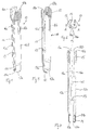
- shows a perspective exploded view of the instrument shown in
Fig. 1 ; - Fig. 3
- shows a cross-sectional view of the assembled instrument of
Fig. 2 with the cross-section taken in a plane perpendicular to a plane of symmetry and including a longitudinal central axis of the instrument. - Fig. 4
- shows a perspective view from above of a holding member of the instrument of
Figs. 1 to 3 . - Fig. 5
- shows a perspective view from the bottom of the holding member of
Fig. 4 . - Fig. 6
- shows a top view of the holding member of
Figs. 4 and 5 . - Fig. 7
- shows a cross-sectional view of the holding member of
Figs. 4 and 5 along line A-A inFig. 6 . - Fig. 8
- shows a perspective view from above of a rod contacting member of the instrument of
Figs. 1 to 3 . - Fig. 9
- shows a perspective view from the bottom of the rod contacting member of
Fig. 8 . - Fig. 10
- shows a top view of the rod contacting member of
Figs. 8 and 9 . - Fig. 11
- shows a cross-sectional view of the rod contacting member of
Figs. 8 and 9 along line B-B inFig. 10 . - Fig. 12
- shows a perspective view from above of an actuating member of the instrument of
Figs. 1 to 3 . - Fig. 13
- shows a perspective view from the bottom of the actuating member shown in
Fig. 12 . - Fig. 14
- shows a top view of the actuating member of
Figs. 12 and 13 . - Fig. 15
- shows a cross-sectional view of the actuating member of
Figs. 12 and 13 along line D-D inFig. 14 . - Figs. 16a to 16e
- show cross-sectional views of steps of use of the instrument during correction of a spinal deformity.
- Fig. 17a
- shows a perspective view of a step of locking a bone anchoring device after the step shown in
Fig. 16e . - Fig. 17b
- shows an enlarged view of a detail of
Fig. 17a . - Fig. 18
- shows a perspective view of a lower end portion of the holding member of the instrument according to a further embodiment.
- Fig. 19
- shows a perspective view from the bottom of a receiving part that is configured to cooperate with the holding member according to
Fig. 18 . - Fig. 20
- shows a cross-sectional view of a portion of the instrument according to the further embodiment together with a receiving part according to
Fig. 19 . - Fig. 21
- shows a perspective view of a lower end portion of a holding member according to a still further embodiment.
- Fig. 22
- shows a perspective view from the bottom of a receiving part that is configured to cooperate with the holding member of
Fig. 21 . - Fig. 23
- shows a cross-sectional view of a portion of the holding member of
Fig. 21 together with a receiving part ofFig. 22 . - Referring to
Figs. 1 to 3 , the instrument includes a holdingmember 10 that is adapted to be attached to a receivingpart 5 of a bone anchoring device and to hold the receivingpart 5. Further, the instrument includes arod contacting member 20 that is adapted to contact arod 100 that is inserted into the receivingpart 5 and connects the receivingparts 5 of a plurality of bone anchoring devices. Each receiving part has abottom end 5a facing the bone surface and an opposite top end 5b. Therod contacting member 20 is connectable to the holdingmember 10 via an actuatingmember 30. The actuatingmember 30 is also configured to move therod contacting member 20 such that therod 100 can be advanced into achannel 52 of the receivingpart 5. - Referring more in detail to
Figs. 4 to 7 , the holdingmember 10 is an elongate member having afirst end 10a and an opposite second end 10b. It is a substantially tubular member with a substantially cylindrical outer surface, a central longitudinal axis C and aslot 11 extending from thefirst end 10a to the second end 10b. By means of theslot 11 twoarms slot 11, has a size such that therod contacting member 20 can be guided therethrough as shown inFig. 3 . At a distance of thefirst end 10a a connectingportion 13 is provided at both sides of the slot 11 (only one side is shown) that connects thearms portion 13 from thefirst end 10a may be smaller than the distance of the connectingportion 13 from the second end 10b. The connectingportion 13 has the shape of an arcuate bridge with a curvature that is concave when seen from thefirst end 10a. The thickness of the connectingportion 13 and the curvature is selected such that the connectingportion 13 acts as a spring between thearms portion 13 forms a fulcrum that permits thearms member 10 to perform a pivoting movement like pliers. Moving thearms arms first end 10a. Thereby an open position of the holdingmember 10 is defined in which a receiving part can be inserted between thearms arms arms first end 10a whereby a closed position is defined in which thearms - The holding
member 10 further comprises anengagement portion 14 at an inner wall of thearms annular projection 14a at thefirst end 10a and at a distance therefrom an annular projection 14b wherein the distance between theannular projections 14a, 14b corresponds substantially to an axial height, i.e. a distance between thebottom end 5a and the top end 5b of a receivingpart 5 to be engaged. An inner contour of theengagement portion 14 corresponds substantially to an outer contour of the receivingpart 5 to be engaged therewith. The size of theengagement portion 14 is such that in the closed position the receivingpart 5 can be held between theprojection 14a at thefirst end 10a and the upper projection 14b in a positive fit manner so that an axial displacement of the receiving part is prevented. - Adjacent to the second end 10b an advancement structure in the form of an
external thread 15 is provided on thearms external thread 15 is configured to engage a corresponding thread in the actuatingmember 30. As depicted inFig. 7 , in the neutral position of thearms arms member 30 can be screwed onto the holdingmember 10 without jamming. - In the vicinity of the
external thread 15 twoelongate windows 16a, 16b, may be provided in the wall of thearms windows 16a, 16b may serve for facilitating cleaning of the instrument. It shall be noted that an outer diameter of the holdingmember 10 may be reduced in the region of theengagement portion 14. This may be of advantage if the receiving parts are placed very close together. Adjacent to the second end 10b, eacharm inner surface portion 17a, 17b that provides an increased inner diameter towards the second end 10b for facilitating the insertion of therod contacting member 20. - Referring now more in detail to
Figs. 8 to 11 , therod contacting member 20 is a substantially tubular member having afirst end 20a and an opposite second end 20b. Atubular connecting portion 21 adjacent to the second end 20b is provided that has a plurality ofslits 22 open to the second end 20b for rendering thetubular connecting portion 21 flexible in a radial direction. Thetubular connecting portion 21 has a greater external diameter than the external diameter of the holdingmember 10 and serves for a snap-in connection with the actuatingmember 30 as described below. For that purpose at the free end of the tubular connecting portion a small collar or thickenedend portion 21a is provided that is configured to snap behind a protrusion in the actuatingmember 30. Abottom end 21b of thetubular connecting portion 21 provides a stop for the second end 10b of the holding member 10 (seeFig. 3 ). - From the
tubular connecting portion 21 twoarms first end 20a. Thearms arms rod contacting member 20 fits in-between thearms member 10 and is guided therebetween. An inner diameter of therod contacting member 20 between thearms tubular connecting portion 21 may be greater than an inner diameter between thearms member 30. - Adjacent to the
first end 20a, each of thearms portion rod contacting surface 25 that is adapted to contact therod 100. Therod contacting surface 25 may be cylindrical and adapted to the cylindrical shape of therod 100. However, it can also be substantially V-shaped to permit contacting rods with different diameters. At an outer surface of thearms 23b guiding portions arms portions slot 11 of the holdingmember 10. By the provision of the guidingportions rod contacting member 10 can be inserted into the holdingmember 10 only in a position in which the guidingportions slot 11. In this orientation, therod contacting surface 25 is aligned with thechannel 52 in the receiving part and can contact arod 100 placed therein.Additional guiding portions 27a, 27b with a slightly increased outer diameter compared to the basic diameter of thearms tubular portion 21 for additional guidance in the upper portion of theslot 11 of the holdingmember 10. - Turning now to
Figs. 12 to 15 , the actuatingmember 30 is a substantially tubular member with afirst end 30a and an oppositesecond end 30b and an internally threadedportion 31 between thefirst end 30a and thesecond end 30b, wherein the threadedportion 31 cooperates with theexternal thread 15 of the holding member. Adjacent to thefirst end 30a, asection 32 with a slightly greater inner diameter compared to the threadedsection 31 may be provided that facilitates mounting onto thetubular connecting portion 21 of therod contacting member 20. An inner diameter of the threadedportion 31 is greater than an outer diameter of thetubular portion 21 of therod contacting member 20 such that the tubular portion can pass through the internally threadedportion 31. - Between the internally threaded
portion 31 and thesecond end 30b, anaccommodation section 33 is formed that is configured to receive thetubular connecting portion 21 of therod contacting portion 20. At a distance from thesecond end 30b an annular protrusion 33a is provided in theaccommodation section 33 that forms together with thecollar 21a of thetubular connecting portion 21 a holding structure for holding therod contacting member 20 and the actuatingmember 30 together. Thetubular portion 21 of therod contacting member 20 is slightly compressed when inserted into theaccommodation section 33 and when thecollar 21a snaps behind the annular protrusion 33a so that therod contacting member 20 is held in the actuatingmember 30. In the mounted state, therod contacting member 20 is able to rotate with respect to the actuatingmember 30 in the mounted state. Apassage 34 between thesecond end 30b and theaccommodation section 33 has a size so as to permit the insertion of a locking element therethrough. Additionally, the actuatingmember 30 comprises at or near the second end agrip portion 35 at its outer surface with a structure to permit gripping and rotating the actuating member by hand. - The parts of the instrument can be made of a bio-compatible material, such as a bio-compatible metal or a bio-compatible metal alloy, for example stainless steel, titanium, NiTi-alloys, such as Nitinol, magnesium or magnesium alloys or from a bio-compatible plastic material, such as, for example, polyetheretherlcetone (PEEK) or poly-1-lactide acid (PLLA). The parts can be made of the same or of different materials. It should be noted that a NiTi-alloy having super-elastic properties may be used to achieve a spring effect for the connecting
portion 13 of the holdingmember 10. - Referring now to
Figs. 16a to 17b , the use of the instrument will be explained by means of an exemplary correction of a spinal deformity. First, when using minimally invasive surgery, a small incision is made in the skin of the patient and then a plurality of bone anchoring devices, for example three bone anchoring devices, are implanted in the pedicles on each side of adjacent vertebrae (only one side is shown inFigs.1 ,17a and 17b ). The bone anchoring devices may be polyaxial bone anchoring devices with an anchoring element 1 with ashank 2 to be connected to the bone and ahead 3 that is pivotably held in the receivingpart 5 and can be locked at an angle relative to the receiving part via a pressure element 6 (Figs. 16a to 16e ). The receivingparts 5 are pivoted until they are aligned and therod 100 is inserted into the channel. - In one of the outer receiving
parts 5 alocking element 7, for example a set screw, is inserted to fix therod 100 and the head of the bone anchoring element 1 in the receivingpart 5. Usually, therod 100 is seated in the bottom of the channel of the twoouter receiving parts 5. Between the bottom of the channel of the middle receiving part and the rod there may be a gap and the middle receiving part is pulled towards therod 100 using the instrument as described in the following. - As illustrated in
Fig. 16a , first, the holdingmember 10 is moved towards the receivingpart 5. At this stage, the holding member is not assembled with therod contacting member 20. Therefore, thearms arms first end 10a as depicted inFig. 16a to assume the open position. In the open position, the holdingmember 10 can be placed onto the receiving part as illustrated inFig. 16b . Correct alignment of the instrument is guaranteed by the insertedrod 100 that has to enter in-between the arms and by the guidance of therod contacting member 20 in the holdingmember 10. When the holdingmember 10 is moved further downwards, thefirst end 10a of thearms part 5 until it slides under thebottom end 5a of the receiving part. Due to the biasing force of the connectingportion 13, thearms Fig. 16c when thearms engagement portion 14 engages the receiving part from the bottom end to the top end 5b, wherein theinner projections 14a, 14b hold the receivingpart 5 in a positive-fit member in an axial direction so that the holdingmember 10 can not slip off. - Thereafter, as depicted in
Fig. 16d , the actuatingmember 30 that is preassembled with therod contacting member 20 is inserted in-between thearms member 10 in such an orientation that the guidingportions slot 11 and guide therod contacting member 20 therein. The actuatingmember 30 is screwed onto the holdingmember 10 until therod contacting surface 25 of therod contacting member 20 contacts the insertedrod 100 as shown inFig. 16d . Next, as depicted inFig. 16e , further downward screwing of the actuatingmember 30 pulls the receivingpart 5 that is held by the holdingmember 10 upward towards therod 100. Because therod contacting member 20 is rotatably held in the actuatingmember 30, it can function as a counter-holding portion for the upward movement of the receivingpart 5. The vertebra moves together with the receivingpart 5 slightly upward, until therod 100 is seated in the bottom of thechannel 52. Finally, as depicted inFigs. 17a and 17b , alocking element 7 is placed with atool 40 through the instrument into the receivingpart 5 and tightened to lock therod 100 and the receivingpart 5 with respect to each other and also to lock the angular position of the bone anchoring element 1 with respect to the receivingpart 5. - Referring to
Fig. 18 , a further embodiment of the instrument comprises a holding member 10' that differs from the holding member of the previous embodiment. Parts and portions of the instrument that are identical or highly similar to that of the previous embodiment are indicated with the same reference numerals and the description thereof will not be repeated. The holding member 10' comprises anannular groove 140a at an inner wall of theannular projection 14a at thefirst end 10a. More in detail, theannular groove 140a is arranged such that it faces in a direction towards the second end 10b of the holding member. Theannular groove 140a extends in a circumferential direction along the wholeannular projection 14a. A cross-section of theannular groove 140a may be circular segment-shaped. However, any cross-section that allows an engagement with a corresponding portion of the receiving part may be also selected for thegroove 140a. Preferably, however, thegroove 140a has a rounded contour. Thegroove 140a may be shallow so as to allow an easy engagement with the receiving part. - As shown in
Fig. 19 , a receiving part 5' that is configured to be engaged with the instrument differs from the receivingpart 5 of the previous embodiment, that it comprises acircular protrusion 50a at thebottom end 5a that is at such a distance from the central axis C that it can engage theannular groove 140a of the holding member 10'. Also the shape and size of theprotrusion 50a is such that theprotrusion 50a fits into theannular groove 140a of the holding member 10'. As shown inFig. 19 , the protrusion extends completely around the central axis at thebottom end 5a, however, it may also be sufficient, that the protrusion is only at the sides of thechannel 52 for receiving the rod. - In use, the holding member is brought into the open position, where the
arms first end 10a and placed onto the receiving part 5' until thearms bottom end 5a of the receiving part 5'. When thearms Fig. 20 , theannular protrusion 50a at thebottom end 50a of the receiving part 5' snaps into theannular groove 140a of the holding member 10'. The engagement of theannular protrusion 50a and theannular groove 140a increases the holding force exerted by the holding member 10'. In the configuration shown inFig. 20 , therod contacting member 20 holds the lockingmember 7 and can tighten it to fix the rod. - In a still further embodiment as depicted in
Figs. 21 to 23 , a holdingmember 10" comprises anannular protrusion 140c of theannular projection 14a. The receivingpart 5" comprises a complementaryannular groove 50c at thebottom end 5a that is configured to cooperate with theannular protrusion 140c. The use and effect of the cooperating grooves and protrusions is the same as for the previous embodiment.Fig. 23 shows the engagement of theannular protrusion 140c at the holdingmember 10" in theannular groove 50c of the receiving part. - A system including the instrument as described before and a receiving part comprises a holding
member 10, 10' that has anengagement portion 14, 14' for engaging the receiving part, wherein the engagement portion is configured to engage the receivingpart 5, 5' at thebottom end 5a. It may be further configured to encompass the receivingpart 5, 5' from thebottom end 5a to the top end 5b. - Modifications of the above-described embodiments are conceivable. For the bone anchoring device all kinds of bone anchoring devices can be used, such as monoaxial screws, where the anchoring section and the receiving part are fixedly connected to each other, polyaxial bone anchoring devices of the top-loading type, where the bone anchoring element is mountable from the top end into the receiving part, or of the bottom-loading type, where the bone anchoring element is mountable from the bottom end of the receiving part or any other bone anchoring devices that are connectable to a rod.
- The connection between the
rod contacting member 20 and the holdingmember 10 can be realized in other ways. For example, thetubular connecting portion 21 may be solid, without exhibiting flexibility, and one or more flexible members inside the actuatingmember 30 may snap into the tubular connecting portion. - The shape of the connecting
portion 13 of the twoarms annular projections 14a, 14b at the holding member that engage the receivingpart 5 need not to be fully annular, any portions that can engage and hold the receiving part may be sufficient.
Claims (15)
- Instrument for use with a bone anchoring device in spinal surgery,
wherein the bone anchoring device (1) includes a bone anchoring section (2) and a receiving part (5) having a bottom end (5a) adjacent to the bone anchoring section, a top end (5b) opposite to the bottom end (5a) and channel (52) for receiving a rod (100), the channel (52) having a bottom for supporting the rod, the instrument including
a holding member (10, 10', 10") that is configured to hold the receiving part (5),wherein the holding member (10, 10', 10") comprises a first arm (12a) and a second arm (12b) that are movable relative to each other between an open position in which the receiving part (5) is insertable between the first arm (12a) and the second arm (12b) into a closed position in which the receiving part (5) is held between the first arm (12a) and the second arm (12b), and a rod contacting member (20) that is configured to contact the rod (100),wherein the rod contacting member (20) is movable between the first arm (12a) and the second arm (12b) such that in the closed position of the first arm (12a) and second arm (12b) the rod contacting member can be advanced to move the rod towards the bottom of the channel; and wherein the holding member (10) comprises an engagement portion (14) at the arms (12a, 12b) that is adapted to engage the receiving part (5) at the bottom end (5a). - The instrument of claim 1 wherein the engagement portion (14) comprises a lower projection (14a) and an upper projection (14b) that have a distance from each other that mates a distance between the bottom end (5a) and the top end (5b) of the receiving part (5, 5', 5") so that the engagement portion (14) engages the receiving part (5, 5', 5") at the bottom end (5b) and at the top end (5a).
- The instrument of claim 1 or 2, wherein the first arm (12a) and the second arm (12b) each have a first end (10a) and a second end (10b) and wherein the arms (12a, 12b) are connected to each other at a position between the first end (10a) and the second end (10b) in a pliers-like manner such that moving the second ends (10b) towards each other moves the first ends (10a) away from each other.
- The instrument of claim 3, wherein the first arm (12a) and the second arm (12b) are connected via a spring portion (13).
- The instrument of one of claims 1 to 4, wherein in the closed position the arms (12a, 12b) are substantially parallel.
- The instruments of one of claims 1 to 5, wherein the holding member (10, 10', 10") is a monolithic piece.
- The instrument of one of claims 1 to 6, further comprising an actuating member (30) for actuating the rod contacting member (20), wherein the actuating member (30) is connectable to the holding member (10, 10', 10") and connectable to the rod contacting member (20).
- The instrument of claim 7, wherein when the actuating member (30) is connected to the holding member it holds the arms (12a, 12b) in the closed position.
- The instrument of claim 7 or 8, wherein the first arm (12a) and the second arm (12b) comprise an external advancement structure (15) on an outer surface portion and wherein the actuating member (30) comprises an internal advancement structure (31) cooperating with the external advancement structure (15) such that by rotating the actuating member (30) the actuating member (30) is displaced along the arms (12a, 12b), and wherein the advancement structure is preferably a thread.
- The instrument of one of claims 7 to 9, wherein the rod contacting member (20) is rotatably connectable to the actuating member (30) such that when the actuating member (30) is rotated the rod contacting member (20) is displaced relative to the arms (12a, 12b).
- The instrument of claim 10, wherein the connection between the rod contacting member (20) and the actuating member (30) is a snap connection.
- The instrument of one of claims 1 to 11, wherein the rod contacting member (20) is a slotted sleeve a first end (20a) of which comprises a rod contacting surface (25).
- The instrument of one of claims 1 to 14, wherein the instrument comprises a longitudinal passage for passing through a locking element (7) for locking the rod in the receiving part.
- A system of a bone anchoring device, wherein the bone anchoring device includes a bone anchoring section (2) and a receiving part (5, 5', 5") having a bottom end (5a) adjacent to the bone anchoring section, a top end (5b) opposite to the bottom end (5a) and channel (52) for receiving a rod (100), the channel (52) having a bottom for supporting the rod ;
and an instrument according to one of claims 1 to 14. - The system of claim 14, wherein the receiving part (5"), comprises at the bottom end (5a) an engagement structure, such as a groove (50c), or a protrusion (50a) that is configured to cooperate with a complementary engagement structure (140c, 50c), at the holding member (10', 10").
Priority Applications (5)
| Application Number | Priority Date | Filing Date | Title |
|---|---|---|---|
| EP16159882.6A EP3092965B1 (en) | 2015-05-15 | 2016-03-11 | Instrument for use with a bone anchoring device in spinal surgery and system including the instrument and a bone anchoring device |
| JP2016095236A JP6580517B2 (en) | 2015-05-15 | 2016-05-11 | Instruments used with bone fixation devices in spinal surgery, and systems for bone fixation devices |
| CN201610308088.2A CN106137365A (en) | 2015-05-15 | 2016-05-11 | For the apparatus being used together with bone anchoring device and the system including apparatus and bone anchoring device in spinal operation |
| KR1020160058226A KR20160134546A (en) | 2015-05-15 | 2016-05-12 | Instrument for use with a bone anchoring device in spinal surgery and system including the instrument and a bone anchoring device |
| US15/153,909 US9962197B2 (en) | 2015-05-15 | 2016-05-13 | Instrument for use with a bone anchoring device in spinal surgery and system including the instrument and a bone anchoring device |
Applications Claiming Priority (2)
| Application Number | Priority Date | Filing Date | Title |
|---|---|---|---|
| EP15167800 | 2015-05-15 | ||
| EP16159882.6A EP3092965B1 (en) | 2015-05-15 | 2016-03-11 | Instrument for use with a bone anchoring device in spinal surgery and system including the instrument and a bone anchoring device |
Publications (2)
| Publication Number | Publication Date |
|---|---|
| EP3092965A1 true EP3092965A1 (en) | 2016-11-16 |
| EP3092965B1 EP3092965B1 (en) | 2020-11-18 |
Family
ID=53180573
Family Applications (1)
| Application Number | Title | Priority Date | Filing Date |
|---|---|---|---|
| EP16159882.6A Active EP3092965B1 (en) | 2015-05-15 | 2016-03-11 | Instrument for use with a bone anchoring device in spinal surgery and system including the instrument and a bone anchoring device |
Country Status (5)
| Country | Link |
|---|---|
| US (1) | US9962197B2 (en) |
| EP (1) | EP3092965B1 (en) |
| JP (1) | JP6580517B2 (en) |
| KR (1) | KR20160134546A (en) |
| CN (1) | CN106137365A (en) |
Cited By (1)
| Publication number | Priority date | Publication date | Assignee | Title |
|---|---|---|---|---|
| WO2020201376A1 (en) * | 2019-04-01 | 2020-10-08 | Aesculap Ag | Spinal deformity derotation instrument |
Families Citing this family (12)
| Publication number | Priority date | Publication date | Assignee | Title |
|---|---|---|---|---|
| EP2996591B1 (en) * | 2013-05-13 | 2020-11-04 | Neo Medical SA | Orthopedic implant kit |
| EP3106110B1 (en) * | 2015-06-16 | 2017-10-11 | Biedermann Technologies GmbH & Co. KG | Extension device for a bone anchor |
| DE102016106608A1 (en) | 2016-04-11 | 2017-10-12 | Aesculap Ag | Instrument for guiding a rod into an implant receptacle |
| US10485590B2 (en) * | 2017-01-18 | 2019-11-26 | K2M, Inc. | Rod reducing device |
| US10610269B2 (en) | 2017-09-05 | 2020-04-07 | Medos International Sarl | Modular surgical instruments and related methods |
| US11364061B2 (en) * | 2017-09-27 | 2022-06-21 | Jace Medical, Llc | Implant positioning devices and methods |
| US10959859B2 (en) * | 2018-07-25 | 2021-03-30 | Warsaw Orthopedic, Inc. | Spinal implant system and method |
| US11291481B2 (en) * | 2019-03-21 | 2022-04-05 | Medos International Sarl | Rod reducers and related methods |
| US11553947B2 (en) | 2019-07-16 | 2023-01-17 | Aesculap Implant Systems, Llc | Spinal deformity sequential persuader |
| US11439450B2 (en) | 2019-12-13 | 2022-09-13 | Jace Medical, Llc | Screw guides for bone plates |
| DE102022120383A1 (en) * | 2021-08-13 | 2023-02-16 | Zimmer Biomet Spine, Inc. | REDUCING PIECE FOR A STABILIZATION ELEMENT IN SPINE SURGERY |
| DE102022120382A1 (en) * | 2021-08-13 | 2023-02-16 | Zimmer Biomet Spine, Inc. | BONE FIXING TOWER ASSEMBLY FOR SPINE SURGERY |
Citations (12)
| Publication number | Priority date | Publication date | Assignee | Title |
|---|---|---|---|---|
| FR2677242A1 (en) * | 1991-06-05 | 1992-12-11 | Jeanson Jean Francois | Push-bar device for spinal support |
| DE29606468U1 (en) * | 1996-04-09 | 1997-08-07 | Link Waldemar Gmbh Co | Spinal fixator |
| US20040143265A1 (en) | 2002-10-30 | 2004-07-22 | Landry Michael E. | Spinal stabilization systems and methods using minimally invasive surgical procedures |
| US20080045950A1 (en) * | 2006-08-17 | 2008-02-21 | Warsaw Orthopedic, Inc. | Reducing device |
| US20080077134A1 (en) | 2006-09-26 | 2008-03-27 | Depuy Spine, Inc. | Minimally invasive bone anchor extensions |
| WO2010030916A2 (en) * | 2008-09-12 | 2010-03-18 | Synthes Usa, Llc | Reduction tool |
| US20120271365A1 (en) * | 2008-12-17 | 2012-10-25 | Synthese USA, LLC | Rod reducer apparatus for spinal corrective surgery |
| US20130030445A1 (en) * | 2011-07-29 | 2013-01-31 | Aesculap Inplant Systems, LLC | Surgical instrumentation for spinal surgery |
| FR2985166A1 (en) * | 2012-01-02 | 2013-07-05 | Iceram | Rod push instrument e.g. pedicular screw, for use in operating block during intervention of spinal column, has cylindrical interior part including jaws deviating toward outside, and protruding pins that allow apprehending of implant |
| US8636776B2 (en) | 2003-01-28 | 2014-01-28 | Depuy Spine, Inc. | Spinal rod approximator |
| US20140163625A1 (en) * | 2012-08-03 | 2014-06-12 | Alphatec Spine, Inc. | Instrument and method for reducing and securing spinal rods |
| US20140277137A1 (en) * | 2013-03-14 | 2014-09-18 | DePuy Synthes Products, LLC | Devices and methods for monoaxial screw conversion |
Family Cites Families (7)
| Publication number | Priority date | Publication date | Assignee | Title |
|---|---|---|---|---|
| MXPA06007105A (en) * | 2003-12-17 | 2007-01-19 | Johnson & Johnson | Instruments and methods for bone anchor engagement and spinal rod reduction. |
| US7491207B2 (en) | 2004-04-12 | 2009-02-17 | Synthes Usa, Llc | Rod persuader |
| US9198692B1 (en) * | 2011-02-10 | 2015-12-01 | Nuvasive, Inc. | Spinal fixation anchor |
| ES2616212T3 (en) * | 2012-10-09 | 2017-06-09 | Biedermann Technologies Gmbh & Co. Kg | Mounting instrument for a polyaxial bone anchoring device |
| ES2611158T3 (en) * | 2013-07-24 | 2017-05-05 | Biedermann Technologies Gmbh & Co. Kg | Coupling assembly for coupling a rod to a bone anchoring element, kit for such coupling assembly and different rod receiving elements, and bone anchoring device |
| US9271768B2 (en) * | 2013-12-20 | 2016-03-01 | Globus Medical, Inc. | Orthopedic fixation devices and instruments for installation thereof |
| US9622794B2 (en) | 2014-02-24 | 2017-04-18 | Hans Robert Tuten | Polyaxial pedicle screw locking and derotation instrument |
-
2016
- 2016-03-11 EP EP16159882.6A patent/EP3092965B1/en active Active
- 2016-05-11 JP JP2016095236A patent/JP6580517B2/en active Active
- 2016-05-11 CN CN201610308088.2A patent/CN106137365A/en active Pending
- 2016-05-12 KR KR1020160058226A patent/KR20160134546A/en unknown
- 2016-05-13 US US15/153,909 patent/US9962197B2/en active Active
Patent Citations (12)
| Publication number | Priority date | Publication date | Assignee | Title |
|---|---|---|---|---|
| FR2677242A1 (en) * | 1991-06-05 | 1992-12-11 | Jeanson Jean Francois | Push-bar device for spinal support |
| DE29606468U1 (en) * | 1996-04-09 | 1997-08-07 | Link Waldemar Gmbh Co | Spinal fixator |
| US20040143265A1 (en) | 2002-10-30 | 2004-07-22 | Landry Michael E. | Spinal stabilization systems and methods using minimally invasive surgical procedures |
| US8636776B2 (en) | 2003-01-28 | 2014-01-28 | Depuy Spine, Inc. | Spinal rod approximator |
| US20080045950A1 (en) * | 2006-08-17 | 2008-02-21 | Warsaw Orthopedic, Inc. | Reducing device |
| US20080077134A1 (en) | 2006-09-26 | 2008-03-27 | Depuy Spine, Inc. | Minimally invasive bone anchor extensions |
| WO2010030916A2 (en) * | 2008-09-12 | 2010-03-18 | Synthes Usa, Llc | Reduction tool |
| US20120271365A1 (en) * | 2008-12-17 | 2012-10-25 | Synthese USA, LLC | Rod reducer apparatus for spinal corrective surgery |
| US20130030445A1 (en) * | 2011-07-29 | 2013-01-31 | Aesculap Inplant Systems, LLC | Surgical instrumentation for spinal surgery |
| FR2985166A1 (en) * | 2012-01-02 | 2013-07-05 | Iceram | Rod push instrument e.g. pedicular screw, for use in operating block during intervention of spinal column, has cylindrical interior part including jaws deviating toward outside, and protruding pins that allow apprehending of implant |
| US20140163625A1 (en) * | 2012-08-03 | 2014-06-12 | Alphatec Spine, Inc. | Instrument and method for reducing and securing spinal rods |
| US20140277137A1 (en) * | 2013-03-14 | 2014-09-18 | DePuy Synthes Products, LLC | Devices and methods for monoaxial screw conversion |
Cited By (2)
| Publication number | Priority date | Publication date | Assignee | Title |
|---|---|---|---|---|
| WO2020201376A1 (en) * | 2019-04-01 | 2020-10-08 | Aesculap Ag | Spinal deformity derotation instrument |
| CN113631109A (en) * | 2019-04-01 | 2021-11-09 | 蛇牌股份公司 | Spinal deformity rotation-removing instrument |
Also Published As
| Publication number | Publication date |
|---|---|
| JP6580517B2 (en) | 2019-09-25 |
| CN106137365A (en) | 2016-11-23 |
| US9962197B2 (en) | 2018-05-08 |
| KR20160134546A (en) | 2016-11-23 |
| US20160331420A1 (en) | 2016-11-17 |
| JP2016214847A (en) | 2016-12-22 |
| EP3092965B1 (en) | 2020-11-18 |
Similar Documents
| Publication | Publication Date | Title |
|---|---|---|
| EP3092965B1 (en) | Instrument for use with a bone anchoring device in spinal surgery and system including the instrument and a bone anchoring device | |
| US11446066B2 (en) | Instruments and methods for manipulating vertebra | |
| US20210338287A1 (en) | Coupling assembly for coupling a rod to a bone anchoring element, polyaxial bone anchoring device and modular stabilization device | |
| US8685029B2 (en) | Rod reduction instrument and methods of rod reduction | |
| EP3199115B1 (en) | System for spinal implant placement | |
| US8888819B2 (en) | Connector for securing an offset spinal fixation element | |
| US7491207B2 (en) | Rod persuader | |
| US8617165B2 (en) | Rod reducing instrument and methods of use thereof | |
| US9173687B2 (en) | Fulcrum cap for spinal constructs | |
| EP3092962B1 (en) | Instrument for use with a polyaxial bone anchoring device and system including the instrument and a polyaxial bone anchoring device | |
| US11737791B2 (en) | System and instrument for correcting a position of bones, bone parts, or vertebrae | |
| JP7312575B2 (en) | Polyaxial bone anchoring device and system of instrument and polyaxial bone anchoring device | |
| CN106236230B (en) | Receiving part of a bone anchoring device and bone anchoring device with such a receiving part | |
| US11478289B2 (en) | Compression fixation system |
Legal Events
| Date | Code | Title | Description |
|---|---|---|---|
| PUAI | Public reference made under article 153(3) epc to a published international application that has entered the european phase |
Free format text: ORIGINAL CODE: 0009012 |
|
| AK | Designated contracting states |
Kind code of ref document: A1 Designated state(s): AL AT BE BG CH CY CZ DE DK EE ES FI FR GB GR HR HU IE IS IT LI LT LU LV MC MK MT NL NO PL PT RO RS SE SI SK SM TR |
|
| AX | Request for extension of the european patent |
Extension state: BA ME |
|
| STAA | Information on the status of an ep patent application or granted ep patent |
Free format text: STATUS: REQUEST FOR EXAMINATION WAS MADE |
|
| 17P | Request for examination filed |
Effective date: 20170516 |
|
| RBV | Designated contracting states (corrected) |
Designated state(s): AL AT BE BG CH CY CZ DE DK EE ES FI FR GB GR HR HU IE IS IT LI LT LU LV MC MK MT NL NO PL PT RO RS SE SI SK SM TR |
|
| GRAP | Despatch of communication of intention to grant a patent |
Free format text: ORIGINAL CODE: EPIDOSNIGR1 |
|
| STAA | Information on the status of an ep patent application or granted ep patent |
Free format text: STATUS: GRANT OF PATENT IS INTENDED |
|
| INTG | Intention to grant announced |
Effective date: 20200518 |
|
| GRAJ | Information related to disapproval of communication of intention to grant by the applicant or resumption of examination proceedings by the epo deleted |
Free format text: ORIGINAL CODE: EPIDOSDIGR1 |
|
| STAA | Information on the status of an ep patent application or granted ep patent |
Free format text: STATUS: REQUEST FOR EXAMINATION WAS MADE |
|
| GRAR | Information related to intention to grant a patent recorded |
Free format text: ORIGINAL CODE: EPIDOSNIGR71 |
|
| GRAS | Grant fee paid |
Free format text: ORIGINAL CODE: EPIDOSNIGR3 |
|
| STAA | Information on the status of an ep patent application or granted ep patent |
Free format text: STATUS: GRANT OF PATENT IS INTENDED |
|
| GRAA | (expected) grant |
Free format text: ORIGINAL CODE: 0009210 |
|
| STAA | Information on the status of an ep patent application or granted ep patent |
Free format text: STATUS: THE PATENT HAS BEEN GRANTED |
|
| INTC | Intention to grant announced (deleted) | ||
| AK | Designated contracting states |
Kind code of ref document: B1 Designated state(s): AL AT BE BG CH CY CZ DE DK EE ES FI FR GB GR HR HU IE IS IT LI LT LU LV MC MK MT NL NO PL PT RO RS SE SI SK SM TR |
|
| INTG | Intention to grant announced |
Effective date: 20201012 |
|
| REG | Reference to a national code |
Ref country code: GB Ref legal event code: FG4D |
|
| REG | Reference to a national code |
Ref country code: CH Ref legal event code: NV Representative=s name: NOVAGRAAF INTERNATIONAL SA, CH Ref country code: CH Ref legal event code: EP |
|
| REG | Reference to a national code |
Ref country code: IE Ref legal event code: FG4D |
|
| REG | Reference to a national code |
Ref country code: DE Ref legal event code: R096 Ref document number: 602016047944 Country of ref document: DE |
|
| REG | Reference to a national code |
Ref country code: AT Ref legal event code: REF Ref document number: 1334884 Country of ref document: AT Kind code of ref document: T Effective date: 20201215 |
|
| REG | Reference to a national code |
Ref country code: AT Ref legal event code: MK05 Ref document number: 1334884 Country of ref document: AT Kind code of ref document: T Effective date: 20201118 |
|
| REG | Reference to a national code |
Ref country code: NL Ref legal event code: MP Effective date: 20201118 |
|
| PG25 | Lapsed in a contracting state [announced via postgrant information from national office to epo] |
Ref country code: PT Free format text: LAPSE BECAUSE OF FAILURE TO SUBMIT A TRANSLATION OF THE DESCRIPTION OR TO PAY THE FEE WITHIN THE PRESCRIBED TIME-LIMIT Effective date: 20210318 Ref country code: RS Free format text: LAPSE BECAUSE OF FAILURE TO SUBMIT A TRANSLATION OF THE DESCRIPTION OR TO PAY THE FEE WITHIN THE PRESCRIBED TIME-LIMIT Effective date: 20201118 Ref country code: FI Free format text: LAPSE BECAUSE OF FAILURE TO SUBMIT A TRANSLATION OF THE DESCRIPTION OR TO PAY THE FEE WITHIN THE PRESCRIBED TIME-LIMIT Effective date: 20201118 Ref country code: NO Free format text: LAPSE BECAUSE OF FAILURE TO SUBMIT A TRANSLATION OF THE DESCRIPTION OR TO PAY THE FEE WITHIN THE PRESCRIBED TIME-LIMIT Effective date: 20210218 Ref country code: GR Free format text: LAPSE BECAUSE OF FAILURE TO SUBMIT A TRANSLATION OF THE DESCRIPTION OR TO PAY THE FEE WITHIN THE PRESCRIBED TIME-LIMIT Effective date: 20210219 |
|
| PG25 | Lapsed in a contracting state [announced via postgrant information from national office to epo] |
Ref country code: AT Free format text: LAPSE BECAUSE OF FAILURE TO SUBMIT A TRANSLATION OF THE DESCRIPTION OR TO PAY THE FEE WITHIN THE PRESCRIBED TIME-LIMIT Effective date: 20201118 Ref country code: BG Free format text: LAPSE BECAUSE OF FAILURE TO SUBMIT A TRANSLATION OF THE DESCRIPTION OR TO PAY THE FEE WITHIN THE PRESCRIBED TIME-LIMIT Effective date: 20210218 Ref country code: SE Free format text: LAPSE BECAUSE OF FAILURE TO SUBMIT A TRANSLATION OF THE DESCRIPTION OR TO PAY THE FEE WITHIN THE PRESCRIBED TIME-LIMIT Effective date: 20201118 Ref country code: IS Free format text: LAPSE BECAUSE OF FAILURE TO SUBMIT A TRANSLATION OF THE DESCRIPTION OR TO PAY THE FEE WITHIN THE PRESCRIBED TIME-LIMIT Effective date: 20210318 Ref country code: PL Free format text: LAPSE BECAUSE OF FAILURE TO SUBMIT A TRANSLATION OF THE DESCRIPTION OR TO PAY THE FEE WITHIN THE PRESCRIBED TIME-LIMIT Effective date: 20201118 Ref country code: LV Free format text: LAPSE BECAUSE OF FAILURE TO SUBMIT A TRANSLATION OF THE DESCRIPTION OR TO PAY THE FEE WITHIN THE PRESCRIBED TIME-LIMIT Effective date: 20201118 |
|
| REG | Reference to a national code |
Ref country code: LT Ref legal event code: MG9D |
|
| PG25 | Lapsed in a contracting state [announced via postgrant information from national office to epo] |
Ref country code: HR Free format text: LAPSE BECAUSE OF FAILURE TO SUBMIT A TRANSLATION OF THE DESCRIPTION OR TO PAY THE FEE WITHIN THE PRESCRIBED TIME-LIMIT Effective date: 20201118 |
|
| PG25 | Lapsed in a contracting state [announced via postgrant information from national office to epo] |
Ref country code: RO Free format text: LAPSE BECAUSE OF FAILURE TO SUBMIT A TRANSLATION OF THE DESCRIPTION OR TO PAY THE FEE WITHIN THE PRESCRIBED TIME-LIMIT Effective date: 20201118 Ref country code: SK Free format text: LAPSE BECAUSE OF FAILURE TO SUBMIT A TRANSLATION OF THE DESCRIPTION OR TO PAY THE FEE WITHIN THE PRESCRIBED TIME-LIMIT Effective date: 20201118 Ref country code: CZ Free format text: LAPSE BECAUSE OF FAILURE TO SUBMIT A TRANSLATION OF THE DESCRIPTION OR TO PAY THE FEE WITHIN THE PRESCRIBED TIME-LIMIT Effective date: 20201118 Ref country code: EE Free format text: LAPSE BECAUSE OF FAILURE TO SUBMIT A TRANSLATION OF THE DESCRIPTION OR TO PAY THE FEE WITHIN THE PRESCRIBED TIME-LIMIT Effective date: 20201118 Ref country code: SM Free format text: LAPSE BECAUSE OF FAILURE TO SUBMIT A TRANSLATION OF THE DESCRIPTION OR TO PAY THE FEE WITHIN THE PRESCRIBED TIME-LIMIT Effective date: 20201118 Ref country code: LT Free format text: LAPSE BECAUSE OF FAILURE TO SUBMIT A TRANSLATION OF THE DESCRIPTION OR TO PAY THE FEE WITHIN THE PRESCRIBED TIME-LIMIT Effective date: 20201118 |
|
| REG | Reference to a national code |
Ref country code: DE Ref legal event code: R097 Ref document number: 602016047944 Country of ref document: DE |
|
| PG25 | Lapsed in a contracting state [announced via postgrant information from national office to epo] |
Ref country code: DK Free format text: LAPSE BECAUSE OF FAILURE TO SUBMIT A TRANSLATION OF THE DESCRIPTION OR TO PAY THE FEE WITHIN THE PRESCRIBED TIME-LIMIT Effective date: 20201118 |
|
| PLBE | No opposition filed within time limit |
Free format text: ORIGINAL CODE: 0009261 |
|
| STAA | Information on the status of an ep patent application or granted ep patent |
Free format text: STATUS: NO OPPOSITION FILED WITHIN TIME LIMIT |
|
| 26N | No opposition filed |
Effective date: 20210819 |
|
| PG25 | Lapsed in a contracting state [announced via postgrant information from national office to epo] |
Ref country code: IT Free format text: LAPSE BECAUSE OF FAILURE TO SUBMIT A TRANSLATION OF THE DESCRIPTION OR TO PAY THE FEE WITHIN THE PRESCRIBED TIME-LIMIT Effective date: 20201118 Ref country code: AL Free format text: LAPSE BECAUSE OF FAILURE TO SUBMIT A TRANSLATION OF THE DESCRIPTION OR TO PAY THE FEE WITHIN THE PRESCRIBED TIME-LIMIT Effective date: 20201118 Ref country code: MC Free format text: LAPSE BECAUSE OF FAILURE TO SUBMIT A TRANSLATION OF THE DESCRIPTION OR TO PAY THE FEE WITHIN THE PRESCRIBED TIME-LIMIT Effective date: 20201118 Ref country code: NL Free format text: LAPSE BECAUSE OF FAILURE TO SUBMIT A TRANSLATION OF THE DESCRIPTION OR TO PAY THE FEE WITHIN THE PRESCRIBED TIME-LIMIT Effective date: 20201118 |
|
| PG25 | Lapsed in a contracting state [announced via postgrant information from national office to epo] |
Ref country code: ES Free format text: LAPSE BECAUSE OF FAILURE TO SUBMIT A TRANSLATION OF THE DESCRIPTION OR TO PAY THE FEE WITHIN THE PRESCRIBED TIME-LIMIT Effective date: 20201118 Ref country code: SI Free format text: LAPSE BECAUSE OF FAILURE TO SUBMIT A TRANSLATION OF THE DESCRIPTION OR TO PAY THE FEE WITHIN THE PRESCRIBED TIME-LIMIT Effective date: 20201118 |
|
| REG | Reference to a national code |
Ref country code: BE Ref legal event code: MM Effective date: 20210331 |
|
| PG25 | Lapsed in a contracting state [announced via postgrant information from national office to epo] |
Ref country code: LU Free format text: LAPSE BECAUSE OF NON-PAYMENT OF DUE FEES Effective date: 20210311 Ref country code: FR Free format text: LAPSE BECAUSE OF NON-PAYMENT OF DUE FEES Effective date: 20210331 Ref country code: IE Free format text: LAPSE BECAUSE OF NON-PAYMENT OF DUE FEES Effective date: 20210311 |
|
| PG25 | Lapsed in a contracting state [announced via postgrant information from national office to epo] |
Ref country code: IS Free format text: LAPSE BECAUSE OF FAILURE TO SUBMIT A TRANSLATION OF THE DESCRIPTION OR TO PAY THE FEE WITHIN THE PRESCRIBED TIME-LIMIT Effective date: 20210318 |
|
| PG25 | Lapsed in a contracting state [announced via postgrant information from national office to epo] |
Ref country code: BE Free format text: LAPSE BECAUSE OF NON-PAYMENT OF DUE FEES Effective date: 20210331 |
|
| PG25 | Lapsed in a contracting state [announced via postgrant information from national office to epo] |
Ref country code: HU Free format text: LAPSE BECAUSE OF FAILURE TO SUBMIT A TRANSLATION OF THE DESCRIPTION OR TO PAY THE FEE WITHIN THE PRESCRIBED TIME-LIMIT; INVALID AB INITIO Effective date: 20160311 |
|
| PGFP | Annual fee paid to national office [announced via postgrant information from national office to epo] |
Ref country code: GB Payment date: 20230323 Year of fee payment: 8 Ref country code: DE Payment date: 20230327 Year of fee payment: 8 |
|
| PG25 | Lapsed in a contracting state [announced via postgrant information from national office to epo] |
Ref country code: CY Free format text: LAPSE BECAUSE OF FAILURE TO SUBMIT A TRANSLATION OF THE DESCRIPTION OR TO PAY THE FEE WITHIN THE PRESCRIBED TIME-LIMIT Effective date: 20201118 |
|
| P01 | Opt-out of the competence of the unified patent court (upc) registered |
Effective date: 20230525 |
|
| PGFP | Annual fee paid to national office [announced via postgrant information from national office to epo] |
Ref country code: CH Payment date: 20230402 Year of fee payment: 8 |