EP3085451A1 - Bearing for umbilicus of a fluid processing system - Google Patents
Bearing for umbilicus of a fluid processing system Download PDFInfo
- Publication number
- EP3085451A1 EP3085451A1 EP16166004.8A EP16166004A EP3085451A1 EP 3085451 A1 EP3085451 A1 EP 3085451A1 EP 16166004 A EP16166004 A EP 16166004A EP 3085451 A1 EP3085451 A1 EP 3085451A1
- Authority
- EP
- European Patent Office
- Prior art keywords
- umbilicus
- bearing
- traction
- fluid circuit
- axis
- Prior art date
- Legal status (The legal status is an assumption and is not a legal conclusion. Google has not performed a legal analysis and makes no representation as to the accuracy of the status listed.)
- Granted
Links
Images


Classifications
-
- B—PERFORMING OPERATIONS; TRANSPORTING
- B04—CENTRIFUGAL APPARATUS OR MACHINES FOR CARRYING-OUT PHYSICAL OR CHEMICAL PROCESSES
- B04B—CENTRIFUGES
- B04B9/00—Drives specially designed for centrifuges; Arrangement or disposition of transmission gearing; Suspending or balancing rotary bowls
- B04B9/12—Suspending rotary bowls ; Bearings; Packings for bearings
-
- A—HUMAN NECESSITIES
- A61—MEDICAL OR VETERINARY SCIENCE; HYGIENE
- A61M—DEVICES FOR INTRODUCING MEDIA INTO, OR ONTO, THE BODY; DEVICES FOR TRANSDUCING BODY MEDIA OR FOR TAKING MEDIA FROM THE BODY; DEVICES FOR PRODUCING OR ENDING SLEEP OR STUPOR
- A61M1/00—Suction or pumping devices for medical purposes; Devices for carrying-off, for treatment of, or for carrying-over, body-liquids; Drainage systems
- A61M1/36—Other treatment of blood in a by-pass of the natural circulatory system, e.g. temperature adaptation, irradiation ; Extra-corporeal blood circuits
- A61M1/3621—Extra-corporeal blood circuits
- A61M1/3622—Extra-corporeal blood circuits with a cassette forming partially or totally the blood circuit
- A61M1/36222—Details related to the interface between cassette and machine
- A61M1/362227—Details related to the interface between cassette and machine the interface providing means for actuating on functional elements of the cassette, e.g. plungers
-
- A—HUMAN NECESSITIES
- A61—MEDICAL OR VETERINARY SCIENCE; HYGIENE
- A61M—DEVICES FOR INTRODUCING MEDIA INTO, OR ONTO, THE BODY; DEVICES FOR TRANSDUCING BODY MEDIA OR FOR TAKING MEDIA FROM THE BODY; DEVICES FOR PRODUCING OR ENDING SLEEP OR STUPOR
- A61M1/00—Suction or pumping devices for medical purposes; Devices for carrying-off, for treatment of, or for carrying-over, body-liquids; Drainage systems
- A61M1/36—Other treatment of blood in a by-pass of the natural circulatory system, e.g. temperature adaptation, irradiation ; Extra-corporeal blood circuits
- A61M1/3621—Extra-corporeal blood circuits
- A61M1/3622—Extra-corporeal blood circuits with a cassette forming partially or totally the blood circuit
- A61M1/36225—Extra-corporeal blood circuits with a cassette forming partially or totally the blood circuit with blood pumping means or components thereof
-
- A—HUMAN NECESSITIES
- A61—MEDICAL OR VETERINARY SCIENCE; HYGIENE
- A61M—DEVICES FOR INTRODUCING MEDIA INTO, OR ONTO, THE BODY; DEVICES FOR TRANSDUCING BODY MEDIA OR FOR TAKING MEDIA FROM THE BODY; DEVICES FOR PRODUCING OR ENDING SLEEP OR STUPOR
- A61M1/00—Suction or pumping devices for medical purposes; Devices for carrying-off, for treatment of, or for carrying-over, body-liquids; Drainage systems
- A61M1/36—Other treatment of blood in a by-pass of the natural circulatory system, e.g. temperature adaptation, irradiation ; Extra-corporeal blood circuits
- A61M1/3693—Other treatment of blood in a by-pass of the natural circulatory system, e.g. temperature adaptation, irradiation ; Extra-corporeal blood circuits using separation based on different densities of components, e.g. centrifuging
- A61M1/3696—Other treatment of blood in a by-pass of the natural circulatory system, e.g. temperature adaptation, irradiation ; Extra-corporeal blood circuits using separation based on different densities of components, e.g. centrifuging with means for adding or withdrawing liquid substances during the centrifugation, e.g. continuous centrifugation
-
- B—PERFORMING OPERATIONS; TRANSPORTING
- B04—CENTRIFUGAL APPARATUS OR MACHINES FOR CARRYING-OUT PHYSICAL OR CHEMICAL PROCESSES
- B04B—CENTRIFUGES
- B04B5/00—Other centrifuges
- B04B5/04—Radial chamber apparatus for separating predominantly liquid mixtures, e.g. butyrometers
- B04B5/0442—Radial chamber apparatus for separating predominantly liquid mixtures, e.g. butyrometers with means for adding or withdrawing liquid substances during the centrifugation, e.g. continuous centrifugation
-
- F—MECHANICAL ENGINEERING; LIGHTING; HEATING; WEAPONS; BLASTING
- F16—ENGINEERING ELEMENTS AND UNITS; GENERAL MEASURES FOR PRODUCING AND MAINTAINING EFFECTIVE FUNCTIONING OF MACHINES OR INSTALLATIONS; THERMAL INSULATION IN GENERAL
- F16C—SHAFTS; FLEXIBLE SHAFTS; ELEMENTS OR CRANKSHAFT MECHANISMS; ROTARY BODIES OTHER THAN GEARING ELEMENTS; BEARINGS
- F16C17/00—Sliding-contact bearings for exclusively rotary movement
- F16C17/12—Sliding-contact bearings for exclusively rotary movement characterised by features not related to the direction of the load
-
- B—PERFORMING OPERATIONS; TRANSPORTING
- B04—CENTRIFUGAL APPARATUS OR MACHINES FOR CARRYING-OUT PHYSICAL OR CHEMICAL PROCESSES
- B04B—CENTRIFUGES
- B04B5/00—Other centrifuges
- B04B5/04—Radial chamber apparatus for separating predominantly liquid mixtures, e.g. butyrometers
- B04B5/0442—Radial chamber apparatus for separating predominantly liquid mixtures, e.g. butyrometers with means for adding or withdrawing liquid substances during the centrifugation, e.g. continuous centrifugation
- B04B2005/0492—Radial chamber apparatus for separating predominantly liquid mixtures, e.g. butyrometers with means for adding or withdrawing liquid substances during the centrifugation, e.g. continuous centrifugation with fluid conveying umbilicus between stationary and rotary centrifuge parts
-
- F—MECHANICAL ENGINEERING; LIGHTING; HEATING; WEAPONS; BLASTING
- F16—ENGINEERING ELEMENTS AND UNITS; GENERAL MEASURES FOR PRODUCING AND MAINTAINING EFFECTIVE FUNCTIONING OF MACHINES OR INSTALLATIONS; THERMAL INSULATION IN GENERAL
- F16C—SHAFTS; FLEXIBLE SHAFTS; ELEMENTS OR CRANKSHAFT MECHANISMS; ROTARY BODIES OTHER THAN GEARING ELEMENTS; BEARINGS
- F16C11/00—Pivots; Pivotal connections
- F16C11/04—Pivotal connections
- F16C11/06—Ball-joints; Other joints having more than one degree of angular freedom, i.e. universal joints
-
- F—MECHANICAL ENGINEERING; LIGHTING; HEATING; WEAPONS; BLASTING
- F16—ENGINEERING ELEMENTS AND UNITS; GENERAL MEASURES FOR PRODUCING AND MAINTAINING EFFECTIVE FUNCTIONING OF MACHINES OR INSTALLATIONS; THERMAL INSULATION IN GENERAL
- F16C—SHAFTS; FLEXIBLE SHAFTS; ELEMENTS OR CRANKSHAFT MECHANISMS; ROTARY BODIES OTHER THAN GEARING ELEMENTS; BEARINGS
- F16C2316/00—Apparatus in health or amusement
- F16C2316/10—Apparatus in health or amusement in medical appliances, e.g. in diagnosis, dentistry, instruments, prostheses, medical imaging appliances
Definitions
- the present disclosure is directed to a bearing and bearing assembly for supporting an umbilicus used, for example, in a fluid processing system.
- Whole blood is routinely separated into its various components, such as red blood cells, platelets, and plasma.
- whole blood may be drawn from a donor, the particular blood component or constituent removed and collected, and the remaining blood constituents returned to the donor.
- the donor's body By thus removing only particular constituents, less time may be needed for the donor's body to return to normal, and donations can be made at more frequent intervals than when whole blood is collected. This may increase the overall supply of blood constituents, such as plasma and platelets, made available for health care.
- Whole blood may be passed through a centrifuge after it is withdrawn from, and before it is returned to, the donor. To avoid contamination, the blood may be contained within a sealed, sterile system during the entire centrifugation process.
- Blood processing systems thus may include a permanent, reusable centrifuge assembly or "hardware” that spins and pumps the blood, and a disposable, sealed and sterile fluid processing or fluid circuit assembly that actually makes contact with the donor's blood.
- the centrifuge assembly may engage and spin a portion of the fluid processing assembly (often called the centrifuge or separation chamber) during a collection procedure.
- the blood may make actual contact only with the fluid processing assembly, which may be used only once and then discarded.
- the present disclosure is directed to a fluid circuit for use with a fluid processing assembly, the fluid circuit comprising an umbilicus having a first end, a second end, an axis of rotation, and a cross-sectional circumference.
- the fluid circuit also comprises a one-piece bearing secured to the umbilicus at a location between the first and second ends, the bearing having an axis of rotation and including an inner lumen which directly engages the umbilicus and includes a plurality of traction features, which bear against the umbilicus to prevent relative rotation of the bearing and the umbilicus.
- the plurality of traction features comprises a first traction feature configured to engage the umbilicus at a first length between the first and second ends and a second traction feature configured to engage the umbilicus at a second length between the first and second ends.
- the traction features are oriented transversely to the axis of rotation of the bearing and umbilicus.
- the cross section of the umbilicus at the first and second lengths have generally ovular shapes when engaged by the traction features.
- the traction features are disposed on tabs circumferentially disposed about the axis of rotation of the bearing.
- the first traction feature and a third traction feature are disposed on a first tab.
- the third traction feature is configured to engage the umbilicus at a third length between the first and second ends.
- a third traction feature is disposed diametrically opposed to the first traction feature about the cross-section of the umbilicus at the first length of the umbilicus.
- the umbilicus comprises material that includes a thermoplastic elastomer.
- the present disclosure is directed to a fluid circuit for use with a fluid processing assembly, the fluid circuit comprising an umbilicus having a first end, a second end, an axis of rotation, and a cross-sectional circumference.
- the fluid circuit also comprises a one-piece bearing secured to the umbilicus at a location between the first and second ends, the bearing having an axis of rotation and including an inner lumen which directly engages the umbilicus and includes a plurality of tabs disposed about the axis of rotation of the umbilicus.
- the plurality of tabs comprise a first tab having a first configuration of one or more traction features, a second tab having a second configuration of one more traction features, a third tab having the first configuration of one or more traction features, and a fourth tab having the second configuration of one or more traction features.
- the one or more traction features bear against the umbilicus at one or more compression locations to prevent relative rotation of the bearing and the umbilicus.
- the traction features are oriented transversely to the axis of rotation of the bearing and umbilicus.
- the first configuration of one or more traction features comprises at least one traction feature positioned at a first location between the first and second ends of the umbilicus and the second configuration of one or more traction features comprises at least one traction feature positioned at a second location between the first and second ends of the umbilicus.
- the first configuration on the first tab comprises a first traction feature configured to engage the umbilicus at a first length between the first and second ends and a second traction feature configured to engage the umbilicus at a second length between the first and second ends.
- the one or more compression locations of the umbilicus have generally ovular cross-sectional shapes when engaged by the traction features.
- the tabs are disposed circumferentially about the axis of rotation of the bearing.
- the first and third tabs are disposed diametrically opposed to each other about the cross-section of the umbilicus, and the second and fourth tabs are disposed diametrically opposed to each other about the cross-section of the umbilicus.
- the umbilicus comprises material including a thermoplastic elastomer.
- the present disclosure is directed to a fluid circuit for use with a fluid processing assembly, the fluid circuit comprising an umbilicus having a first end, a second end, an axis of rotation, and a generally circular cross-section having a circumference.
- the fluid circuit also comprises a one-piece bearing secured to the umbilicus at a location between the first and second ends, the bearing having an axis of rotation and including an inner lumen which directly engages the umbilicus and includes a plurality of traction features, which bear against the umbilicus at compression locations to prevent relative rotation of the bearing and the umbilicus.
- the plurality of traction features comprise a first traction feature configured to engage the umbilicus at a first compression location at a designated length between the first and second ends at a first point along the circumference, and a second traction feature configured to engage the umbilicus at a second compression location at the designated length at a second point along the circumference.
- the cross-sectional shape of the umbilicus at the designated length is non-circular.
- the traction features are disposed on tabs circumferentially disposed about the axis of rotation of the bearing.
- the first and second compression locations are disposed diametrically opposed to each other about the cross-section of the umbilicus.
- the plurality of traction features further comprise a third traction feature configured to engage the umbilicus at a third compression location at a second designated length at a third point along the circumference, and a fourth traction feature configured to engage the umbilicus at a fourth compression location at the second designated length at a fourth point along the circumference; and wherein the umbilicus comprises material including a thermoplastic elastomer.
- the first and second compression locations have an angular relationship of 120 degrees about the cross-sectional circumference.
- blood processing systems may often utilize centrifuges that operate on the "one-omega, two-omega" operating principle. This principle is disclosed in detail in U.S. Pat. No. 4,120,449 to Brown et al. , which is hereby incorporated by reference in its entirety, and enables centrifuges to spin a sealed, closed system without the need for rotating seals and without twisting the components of the system.
- Blood processing systems may typically include a fluid processing assembly that includes a plastic bag or molded chamber that is spun in the centrifuge and that is connected to the blood donor and to a stationary portion of the centrifuge assembly through an elongated member that may be made up of one or more plastic tubes.
- the elongated member is commonly referred to as an "umbilicus” and may typically be arranged in a question mark (or upside-down question mark) configuration with both of its end portions coaxially aligned with the axis of rotation of the centrifuge.
- the centrifuge chamber may be rotated at "two-omega" RPM and the umbilicus may be orbited around the centrifuge chamber at "one-omega” RPM.
- one end of the umbilicus may be stationary, the other end may rotate at a two-omega speed with the centrifuge chamber to which it is attached, and the intermediate portion or midsection of the umbilicus may orbit about the chamber at a one-omega speed.
- the effect is that the end of the umbilicus, which may be opposite the bag or chamber and may be connected to the donor via plastic tubing, may not twist up as the bag is spun. The sealed, sterile integrity of the fluid processing assembly may thus be maintained without the need for rotating seals.
- a disposable fluid processing assembly having an umbilicus and a processing chamber may be mountable within a centrifuge assembly.
- One end of the umbilicus may be held rotationally stationary substantially coaxial with the axis of centrifugal rotation.
- the other end of the umbilicus may join the processing chamber and rotate with the processing chamber around the axis of centrifugation at the two-omega speed, up to about 3,000 RPM.
- the mid-portion of the umbilicus may be supported by a wing plate that rotates around the axis of centrifugation at the one-omega speed, up to about 1,500 RPM.
- a thrust bearing mounted on the umbilicus may permit the umbilicus to rotate relative to the wing plate as the wing plate and the processing chamber turn at different speeds.
- the thrust bearing may slide into a one piece gimbal mounted in a recess provided on the wing plate. The gimbal may help keep the fluid processing assembly properly positioned during the centrifugation procedure. When the procedure is completed, the thrust bearing may be slid out of the gimbal in the wing plate to permit removal of the fluid processing assembly.
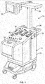
- Fig. 1 shows a centrifugal fluid processing system 10 that may be used in combination with an umbilicus bearing assembly according to the present disclosure.
- the system is currently marketed as the AMICUS® separator by Fenwal, Inc. of Lake Zurich, III.
- the system 10 may be used for processing various fluids, but is particularly well-suited for processing whole blood, blood components, or other suspensions of biological cellular materials.
- the system 10 includes a centrifuge assembly 12 for separating a fluid into its constituent parts. A more detailed description of the centrifuge assembly 12 and the other elements of the system 10 can be found in US. Pat. No. 5,996,634 , which is incorporated by reference herein in its entirety.
- the durable fluid processing system 10 may be used in combination with a disposable processing set or fluid circuit 14, an example of which is shown in Fig. 2 .
- Fig. 3 shows the disposable set 14 mounted on the durable system 10.
- the disposable set 14 may be a single use, disposable item loaded on the system 10 at the time of use. After a fluid processing procedure has been completed, the operator may remove the disposable set 14 from the system 10 and discard it.
- the disposable set 14 includes a processing chamber 16 ( Fig. 2 ).
- the centrifuge assembly 12 may rotate the processing chamber 16 to centrifugally separate blood components.
- Whole blood may be conveyed to the processing chamber 16, and separated blood components may be conveyed from the processing chamber 16, through a plurality of flexible tubes that form part of a fluid circuit 18.
- the fluid circuit 18 may further include a plurality of containers 20 that may be supported by elevated hangers located over the centrifuge assembly 12 (see Fig. 3 ) and that dispense and receive liquids during processing.
- Fluid flow through the fluid circuit 14 may be controlled in a variety of ways. Fluid flow may be controlled via cassettes 22 with preformed fluid passageways, which may be selectively opened and closed pneumatically, hydraulically, or by movable actuators.
- the number of cassettes may vary, but in the illustrated embodiment, there are three cassettes 22, which may operate in association with valve and pump stations on the centrifuge assembly 12 to direct liquid flow among multiple liquid sources and destinations during a blood processing procedure.
- Tubes connected to the processing chamber 16 may lead to a flexible umbilicus 24, with additional tubes at the other end of the umbilicus 24 fluidly connecting the processing chamber 16 (via the umbilicus 24) to the remainder of the disposable set 14, including the containers 20 and the cassettes 22.
- the disposable set 14 may be a pre-assembled closed system, assuring an operator that it is a sterile unit.
- the centrifuge assembly 12 may include a wheeled cabinet 26 that can be easily rolled from place to place.
- a user-actuable processing controller 30 may be provided which enables the operator to control various aspects of the blood processing procedure.
- a centrifuge rotor assembly 32 may be provided behind a fold open door 34 that can be pulled open at the front of the cabinet 26 ( Fig. 3 ).
- a plurality of valve and pump stations 36 ( Fig. 1 ) may be provided on the top face of the cabinet for receiving and controlling the various cassettes 22.
- a plurality of hooks or hangers 38 may be provided on the cabinet 26 for suspending the various containers 20.
- the fold open door 34 may be opened and the processing chamber 16 of the disposable set 14 may be mounted in the centrifuge rotor assembly 32 ( Fig. 4 ).
- the umbilicus 24 may be threaded through the centrifuge rotor assembly 32 and out through an opening 40 in the upper panel of the cabinet 26 ( Fig. 3 ).
- the cassettes 22 may be snapped into respective ones of the valve and pump stations 36 and the containers 20 may be hung from the appropriate hangers 38 ( Fig. 3 ).
- the operator may enter appropriate commands on the processing controller 30 to begin the processing procedure.
- the centrifuge rotor assembly 32 may include a chamber assembly 42 that may be supported for rotation around an axis of centrifugation 44.
- the centrifuge may further include a centrifuge yoke assembly 46 that includes a yoke base 48, a pair of upstanding yoke arms 50, and a yoke cross member 52 mounted between the arms 50.
- the yoke base 48 may be rotatably supported on a stationary platform 54 that carries the rotating mass of the centrifuge rotor assembly 32.
- the yoke base 48 may also be supported for rotation around the axis of centrifugation independently of the chamber assembly 42.
- An electric drive 56 may rotate the yoke assembly 46 relative to the stationary platform 54 around the axis of centrifugation 44.
- the chamber assembly 42 may be free to rotate around the axis of centrifugation 44 at a rotational speed that may be different from the rotational speed of the yoke assembly 46.
- the chamber assembly 42 may define an annular chamber 58, centered around the axis of centrifugation 44, for receiving the processing chamber 16 of the disposable set 14.
- the umbilicus 24 may extend through the lower center of the chamber assembly 42 in alignment with the axis of centrifugation 44.
- a first anchor portion 60 integrally molded or otherwise mounted onto the umbilicus 24, may be received in a lowermost umbilicus mount 62 located at the lower center of the chamber assembly 42.
- the first anchor portion 60 and umbilicus mount 62 may function to transfer torque between the umbilicus 24 and chamber assembly 42 so that the chamber assembly 42 may rotate around the axis of centrifugation in response to twisting of the umbilicus 24 around its axis.
- the other end of the umbilicus 24 may be supported by means of a second anchor portion 64 that may be removably received in an upper umbilicus mount 66 positioned over the centrifuge chamber assembly 42 substantially in alignment with the axis of centrifugation 44.
- An over-center clamp 68 at the end of the upper umbilicus mount 66 may clamp onto the second anchor portion 64 to hold the adjacent segment of the umbilicus 24 rotationally stationary and in collinear alignment with the axis of centrifugation 44.
- the second anchor portion 64 may be integrally molded or otherwise securely joined with the umbilicus 24.
- the portion of the umbilicus 24 between the second anchor portion 64 and the first anchor portion 60 may be supported by a middle umbilicus mount or bearing support 70 (illustrated in greater detail in Fig. 5 ) that may be carried at the lower end of a wing plate 72 extending outwardly and downwardly from the yoke cross member 52.
- a middle umbilicus mount or bearing support 70 illustrated in greater detail in Fig. 5
- the electric drive 56 rotates the centrifuge yoke assembly 46 ( Fig. 3 ) around the axis of centrifugation 44
- the wing plate 72 and the bearing support 70 may pull the midsection of the umbilicus 24 around the axis of centrifugation 44 as well.
- the umbilicus 24 may spin the centrifuge chamber assembly 42 around the axis of centrifugation 44 at an average rotational speed of two omega.
- an additional wing plate 74 may extend from the yoke cross member 52 diametrically opposite the wing plate 72.
- a counterweight 76 sufficient to balance the mass of the bearing support 70 and umbilicus 24 may be carried on the lower end of the additional wing plate 74.
- the midsection of the umbilicus 24 may be supported on the wing plate 72 by means of an umbilicus bearing assembly 78, which is shown in greater detail in Figs. 6 and 7 .
- the illustrated umbilicus bearing assembly 78 may include, as illustrated, several distinct parts, one or more of which may be provided as integral combinations with other parts.
- the assembly may include a gimbal or liner receptacle 80, a liner or bearing receptacle 82 at least partially received within the gimbal 80, a one-piece bearing 84 at least partially received within the liner 82, and a retaining member 86 which may secure the bearing 84 within the liner 82.
- fasteners 88 may be provided to secure the gimbal 80 to the liner 82 and a clip 90 in the form of a compression band or other suitable structure may be provided to secure the bearing 84 to the umbilicus 24.
- the gimbal 80 of the umbilicus bearing assembly 78 may be received within the bearing support 70, which is shown in greater detail in Fig. 5 .
- the bearing support 70 may comprise a circular opening 92 formed in the lowermost end of the wing plate 72.
- the side wall 94 of the circular opening 92 may be concavely shaped, thereby giving the opening 92 a generally spherical shape.
- a gap 96 may be formed in the end of the wing plate 72 and may open into the circular opening 92 to enable the umbilicus 24 and the umbilicus bearing assembly 78 to be inserted into the opening 92 from the side.
- a pair of orthogonally oriented pivot pins 98 may extend from the side wall 94 of the circular opening 92 towards its center.
- the gimbal 80 may comprise a "C-shaped" member having a generally annular or ring-like form.
- the outer surface 100 of the illustrated gimbal 80 may be outwardly rounded or convex, thereby giving the gimbal 80 a generally spherical shape that matches the shape of the opening 92 of the bearing support 70.
- a pair of elongated slots 102 (only one of which is visible) may be formed through the outer surface 100 and may be positioned and dimensioned to receive the pivot pins 98 when the gimbal 80 is received in the circular opening 92.
- the rounded outer surface 100 of the gimbal 80, together with the slots 102 and pivot pins 98 received therein, may enable the gimbal 80 to pivot within the circular opening 92 around two orthogonal axes. Such freedom of movement is referred to herein as a "gimbaling" action or motion.
- a gap 104 may be formed through the side of the gimbal 80 to permit entry of the umbilicus 24.
- the gimbal 80 may be formed of a durable, rigid, low-friction plastic such as a Delrin® and/or polytetrafluoroethylene (“PTFE" or Teflon®).
- While such material may be sufficiently rigid to prevent excessive wear during repeated use (the gimbal 80 being considered a part of the durable fluid processing system 10 and not the disposable set 14), it may be slightly flexed by pinching or squeezing (on account of the thickness of the gimbal wall and the presence of the gap 104) so as to be pressed into the circular opening 92 of the bearing support 70.
- the liner or bearing receptacle 82 may comprise a generally "C-shaped" structure with a gap 106 opening through its side to permit passage of the umbilicus 24 during installation.
- the liner 82 may be a reusable component of the umbilicus bearing assembly 78 which may be intended for repeated use as part of the durable fluid processing system 10.
- the liner 82 may be integral and of one-piece construction with the gimbal 80.
- the combination of the gimbal 80 and liner 82 (whether provided separately or integrally) is referred to herein as a gimbal assembly.
- the liner 82 may be configured to be at least partially received within the gimbal 80 ( Fig. 11 ).
- a top surface 108 of the liner 82 may abut an upper ledge or transverse wall 110 of the gimbal 80 when the liner 82 is properly positioned within the gimbal 80, thereby providing tactile feedback and a positive stop during assembly.
- the liner 82 may also include an upper rim 112 which may simultaneously abut a lower ledge or transverse wall 114 of the gimbal 80 when the liner 82 is properly positioned within the gimbal 80.
- Both the gimbal 80 and the liner 82 may include one or more apertures 116, with each aperture 116 of the gimbal 80 being aligned with a corresponding aperture 116 of the liner 82 when the gap 104 of the gimbal 80 is aligned with the gap 106 of the liner 82.
- the apertures 116 so aligned may each accommodate a fastener 88 (such as the threaded screws shown in Figs. 6 and 7 ) to secure the liner 82 within the gimbal 80.
- the liner 82 may be secured to the gimbal 80 either before or after the gimbal 80 is installed within the circular opening 92 of the bearing support 70, though it may be advantageous to first install the gimbal 80 so that it is not necessary to squeeze both the gimbal 80 and the liner 82 upon installation of the gimbal 80 into the circular opening 92. It may be advantageous for there to be some amount of lateral clearance between the outer surface 120 of the liner 82 and the inner surface 122 of the gimbal 80. Such a space may expose the outer surface 120 of the liner 82 to the air within the centrifuge 32, thereby potentially reducing the temperature of the liner 82, which may tend to heat up during fluid processing as a result of friction.
- the illustrated liner 82 may further include an upper section 124 with a relatively small, substantially constant inner diameter (the surface of which is referred to herein as an axially extending wall 126) and a lower section 128 with a relatively large, substantially constant inner diameter ( Fig. 10 ).
- the transition between the upper section 124 and the lower section 18 may be defined by a shoulder or radially-extending liner wall 130, which may extend substantially radially or at a selected angle or incline relative to the center axis.
- the opening defined by the upper section 124 of the liner 82 may be adapted to receive a minor diameter portion 132 of the bearing 84, while the opening defined by the lower section 128 of the liner 82 may be adapted to receive a major diameter portion 134 of the bearing 84, as shown in Fig. 11 .
- the shoulder 130 of the liner 82 may abut a mating bearing surface 136 of the bearing 84 to limit the degree to which the bearing 84 may be inserted into the liner 82 and to provide an arrangement that allows relative rotation between the bearing 84 and the liner 82, while limiting axial movement as a thrust bearing.
- Such a configuration of the inner surface of the liner 82 may be adapted for use with the bearing 84 illustrated in Figs. 7 and 11 and it should be understood that a different configuration for the liner inner surface may be more appropriate when the bearing configuration is different.
- the liner 82 of Figs. 9-11 may also include a generally "U-shaped" perimeter slot or channel or groove 138, which may be defined between the upper rim 112 and a lower rim 140 adjacent to a bottom end of the liner 82.
- the channel 138 may receive the retaining member 86, as shown in Figs. 11 and 12 .
- the illustrated retaining member 86 may include an arcuate crossbeam or cross member 142 (having a curvature substantially the same as the curvature of the channel 138) and a pair of substantially parallel legs 144 extending from the ends of the cross member 142. As shown in Fig.
- the cross member 142 may be positioned diametrically opposite the gap 106 of the liner 82, with the legs 144 extending from the cross member 142 in the direction of the gap 106.
- Two opposing lateral passages 146 may extend through the wall of the liner 82, allowing a portion of each leg 144 of the retaining member 86 to communicate with the open interior of the liner 82 ( Figs. 11 and 12 ).
- the major diameter portion 134 of the bearing 84 may be wider than the separation between the legs 144 ( Fig.
- the legs 144 may be resilient (being made of a material such as stainless steel or spring steel or the like), thereby allowing the major diameter portion 134 of the bearing 84 to press the legs 144 away from each other as the bearing 84 is pressed into the liner 82.
- the legs 144 may resiliently return to their original straight configuration ( Figs. 11 and 12 ), thereby temporarily securing the bearing 84 within the liner 82.
- Such a configuration may provide a tactile and audible indication that the bearing 84 has been successfully loaded into the liner 82.
- the liner 82 may be formed of a durable, high stiffness material such as stainless steel.
- a metallic material may be advantageous for drawing away from the bearing 84 any heat arising from friction generated between the liner 82 and the bearing 84 during fluid processing.
- Stainless steel may be advantageous due to its low corrosion nature and ability to accept a wide range of coatings for further reducing friction between the interior of the liner 82 and the exterior of the bearing 84.
- low friction coatings are polyether ether ketone ("PEEK”), diamond-chrome, and nickel-boron nitride.
- PEEK coating may be advantageous because of its low coefficient of friction, durability, and ability to withstand high temperatures.
- other materials, including solid polymers may also be used without departing from the scope of the present disclosure.
- the one-piece bearing 84 ( Figs. 13 and 14 ) may generally be tubular, with an inner lumen or surface 148 defining an open interior sufficiently sized to accommodate the umbilicus 24.
- the bearing 84 may be slid axially or longitudinally onto and along the umbilicus 24 to a position between the anchor portions 60, 64 ( Fig. 4 ).
- the bearing 84 may be slid into place before one or both of the anchor portions 60, 64 is associated with the umbilicus 24, or otherwise the presence of the anchor portions 60, 64 would prevent proper positioning of the bearing 84.
- the bearing 84 may be oriented with its minor diameter portion 132 facing the upper anchor portion 64 and an attachment portion or flange portion 150 facing the lower anchor portion 60.
- the location of the bearing 84 on the umbilicus 24 is referred to herein as a midsection of the umbilicus 24, although the bearing 84 may not necessarily be located at the midpoint between the upper and lower anchor portions 64 and 60.
- the inner diameter of the bearing 84 may be substantially the same as the outer diameter of the umbilicus 24 to ensure that the umbilicus 24 fits snugly around the bearing 84, thereby preventing radial or lateral movement of the umbilicus 24 within the bearing 84. It may also be advantageous for one end of the inner lumen 148 of the bearing 84 (illustrated in Fig. 11 as the top end) to be outwardly tapered to help guide the umbilicus 24 into the bearing 84 during assembly.
- such a taper may provide a smooth surface to interface with a bending umbilicus 24, thereby reducing stress and easing the shear forces experienced by the bending umbilicus 24 at that location.
- the inner lumen 148 of the bearing 84 may be held in place against the umbilicus 24 by any of a number of acceptable means, including an adhesive or other bonding agent and/or a physical restraint.
- the bearing 84 may be secured to the umbilicus 24 by means of a compression band or clip 90 ( Figs. 6 and 7 ).
- the flange portion 150 of the bearing 84 (illustrated as a bottom end of the bearing 84 in Figs. 13 and 14 ) may include a plurality of spaced-apart flanges or tabs 152 which may be forced radially inwardly toward a central axis of the bearing 84.
- Each flange 152 may have an indentation 154 on its outer surface, which indentations 154 may align to form an annular seat for the clip 90.
- the clip 90 may have a smaller inner diameter than the lower end of the bearing 84, so when it is pushed into contact with the lower end of the bearing 84 (upwardly in the orientation of Fig. 7 ), it may force the flanges 152 radially inwardly, eventually seating within the indentations 154.
- the flanges 152 may grip the umbilicus 24, thereby preventing the bearing 84 from moving with respect to the umbilicus 24.
- the inner surfaces of the flanges 152 may include additional features to promote a secure grip by increasing the force required to cause the bearing 84 to slip axially along the umbilicus 24.
- Fig. 15 shows one embodiment wherein the inner surface of each flange 152 may include a traction feature comprised of a plurality of parallel projections or barbs 156 which are oriented transverse to the central axis of the bearing 84.
- each flange 152 may include a traction feature comprised of a plurality of projections or barbs (156a and 156b) which are oriented transverse to the central axis of the bearing 84 and also oriented in a staggered configuration with respect to projections or barbs 156a, 156b in adjacent flanges 152.
- staggered configuration refers to traction features, such as 156a and 156b, that are staggered such that they are not positioned at identical locations along the longitudinal axis of the bearing 84. A staggered configuration as shown in Fig.
- 15A results in a secure grip which minimizes slippage not only longitudinally along the length of the umbilicus 24, but also rotationally about the central axis of the umbilicus 24 and bearing 84. Rotational slippage may occur as the reactant force of the umbilicus 24 to the bearing 84 decays over time.
- Minimizing rotational slippage which is sometimes due to the necking down (diameter reduction) of the umbilicus 24 to the bearing 84 over time due to the axial load induced by the umbilicus 24 rotating in the g-field for an extended period of time, is desirable to maximize the longevity of the umbilicus 24 during the fluid processing procedure, as extended rotation of the bearing 84 relative to the umbilicus 24 may cause the barbs 156 to cut into the material of the umbilicus 24. Minimizing rotational slippage can therefore also prevent leakage of the fluid through the umbilicus 24.
- Fig. 15B illustrates an embodiment of the shape of the umbilicus 24 fitted within the embodiment of the bearing shown in Fig. 15A .
- the umbilicus 24 may be made of hytrel or any thermoplastic elastomer, which may take a compressive set after the bearing 84 is clamped onto the umbilicus 24, due to the viscoelastic nature of the material.
- the staggered configuration of the projections or barbs 156a, 156b with respect to adjacent flanges 152 results in the umbilicus 24 having a cross-sectional shape that is oval at the location of compression 157a, 157b between the umbilicus 24 and flanges 152.
- the bearing 84 may comprise four flanges or tabs 152 each having a set of barbs 156a, 156b that are staggered relative to adjacent tabs 152 but aligned relative to non-adjacent tabs 152.
- a first barb 156a may be aligned with a second barb 156a that is located on a tab 152 diametrically opposed to the tab of the first barb 156a.
- the first and second barbs 156a may contact the umbilicus 24 in Fig. 15B at two compression locations 157a (only one compression location illustrated), which may be locations diametrically opposed about the cross-section of the umbilicus 24.
- a third barb 156b may be aligned with a fourth barb 156b that is located on a tab 152 diametrically opposed to the tab of the third barb 156b (but adjacent to barbs 156a and staggered relative to barbs 156a).
- the third and fourth barbs 156b may contact the umbilicus 24 at an adjacent cross-sectional point (as shown in Fig. 15B ) at two compression locations 157b (only one compression location illustrated), which may be locations diametrically opposed about the umbilicus cross-section.
- compression locations 157a and 157b may have a 90 degree relationship to each other about the circumference of the umbilicus cross-section such that the oval cross-sections of the umbilicus that result are 90 degree rotations of each other, although any suitable degree of relationship may be used.
- any number of tabs 152 having barbs 156 may be provided, with barb alignment between/among tabs occurring at any angle(s) about the circumference of the cross-section of umbilicus 24.
- the cross-sectional shape that results may thereby comprise any non-circular shape, including an oval shape.
- any number of adjacent non-circular cross-sectional points may be provided.
- a single non-circular cross-sectional point may be provided. In such an embodiment, for example in Fig. 15A , only one set of diametrically opposed tabs 152 may include barbs 156a, while the remaining two tabs may have no barbs 157b.
- the resulting umbilicus 24, for example in Fig. 15B may have a single oval cross-sectional point to resist rotational slippage by virtue of having only one pair of diametrically opposed compression locations 157a, rather than two pairs.
- At least one set of diametrically opposed tabs 152 may have more than one set of barbs 156 such that a single set of diametrically opposed tabs 152 may provide two pairs of diametrically opposed compression locations 157a and 157c ( Fig. 15C ) to create two oval cross-sections.
- the two location pairs 157a and 157c are interposed by compression location pair 157b, which may be created by another set of diametrically opposed tabs 152, each having at least one set of barbs 156b not aligned with any of the two locations pairs 157a and 157c.
- each compression location 157a, 157b, or 157c within a pair of compression locations may have an angular relationship of 120 degrees rather than the diametric relationship of 180 degrees.
- the illustrated embodiment may be comprised of three sections - the minor diameter portion 132, the above-described flange or attachment portion 150, and the major diameter portion 134, which may be positioned between the minor diameter portion 132 and the flange portion 150.
- the transition from the minor diameter portion 132 to the major diameter portion 134 may be defined by the radially-extending bearing surface 136, which may act as a thrust bearing in an axial direction.
- the transition from the major diameter portion 134 to the flange portion 150 may be defined by a lead-out surface 160.
- the minor diameter portion 132 may be substantially tubular, with an outer surface 162 configured to be received within the opening defined by the axially-extending wall 126 of the liner 82 ( Fig. 11 ).
- the outer surface 162 of the minor diameter portion 132 is referred to herein as an axially-extending bearing surface and may be acted on by radial forces.
- the diameter of the axially-extending bearing surface 162 while being smaller than the diameter of the axially extending liner wall 126, may be comparable to the diameter of the axially-extending liner wall 126.
- Such a configuration may have a number of benefits. For example, it may prevent the axially extending bearing surface 162 from binding within the axially-extending liner wall 126.
- the diameters of the axially-extending liner wall 126 and axially-extending bearing surface 162 may be sufficiently close that the axially extending bearing surface 162 may only be allowed a small amount of lateral travel before coming into contact with the axially extending liner wall 126. This may ensure that the bearing 84 remains generally coaxial with the liner 82 during fluid processing for optimal performance.
- the illustrated major diameter portion 134 may be comprised of the radially-extending bearing surface 136, a lead-in surface 164, and the lead-out surface 160.
- the illustrated radially-extending bearing surface 136 may extend from the axially-extending bearing surface 162 in a direction generally away from the central axis of the bearing 84.
- the radially-extending bearing surface 136 may abut the shoulder 130 of the liner 82 ( Fig. 11 ), with the two being oriented at approximately the same angle to maximize the surface contact therebetween.
- Such a configuration may have a number of benefits. For one, it may give the bearing 84 a self-centering feature with respect to the liner 82.
- the liner 82 may press against the bearing 84 with an axial force, but an inclined interface therebetween may give the force a radial component, which may effectively reduce the magnitude of the force in the axial direction.
- the shoulder 130 and radially-extending bearing surface 136 may be inclined and oriented approximately 10° from horizontal, sloping away from the associated axially-extending liner wall 126 and axially-extending bearing surface 162, respectively. While the illustrated angle for the radially-extending bearing surface 136 and the shoulder 130 has been found to be advantageous, other configurations and angles may also be employed without departing from the scope of the present disclosure.
- the illustrated lead-in surface 164 may extend from an outer end of the radially-extending bearing surface 136 and extend radially outwardly therefrom. As shown in Fig. 11 , the lead in surface 164 may be oriented at a sharper incline than the radially extending bearing surface 136. As best illustrated in Fig. 11 , the maximum diameter of the radially-extending bearing surface 136 may be approximately equal to or slightly smaller than the separation between the legs 144 of the retaining member 86. Thus, upon pressing the bearing 84 into the liner 82, the radially-extending bearing surface 136 may pass into the liner 82 without contacting the legs 144 of the retaining member 86.
- the lead-in surface 164 may be wider than the separation between the legs 144, so it may contact the legs 144 as the bearing 84 is pressed into the liner 82. Rather than getting caught upon the legs 144, the incline of the lead-in surface 164 may gradually press the legs 144 away from each other and allow the lead-in surface 164 to pass beyond the legs 144 and into the liner 82.
- the inclination of the lead-in surface 164 may be varied to determine the force required to press the bearing 84 into the liner 82, with greater inclination (i.e., closer to parallel with the central axis of the bearing 84) tending to allow the bearing 84 to be loaded into the liner 82 at a lower insertion force.
- the inclination of the lead-in surface 164 may be approximately 15° from parallel with the central axis of the bearing 84. Such an inclination may be sufficiently great that the bearing 84 can be automatically loaded into the liner 82 upon rotation of the umbilicus 24 as part of a fluid processing procedure.
- lead-in surface 164 having an inclination its configuration is not limited to a strict frusto-conical shape with a uniform inclination.
- the illustrated embodiment may have a lead-in surface 164 which is slightly parabolic or defined by a compound angle.
- Other configurations of the lead-in surface 164 may also be employed without departing from the scope of the present disclosure.
- the outer edge of the lead-in surface 164 may mark the transition between the lead-in surface 164 and the lead-out surface 160.
- the lead-out surface 160 may be inwardly inclined or tapered (i.e., having an outer diameter which decreases as the bearing 84 is inserted into the liner 82).
- the legs 144 may begin to resiliently return to their original straight configuration, pressing toward each other and against the lead-out surface 160.
- the bearing 84 may be temporarily secured within the liner 82, as the lead-out surface 160 cannot exit the liner 82 without being pulled (to press the legs 144 of the retaining member 86 far enough apart from each other so as to allow passage of the lead-out surface 160).
- the lead-out surface 160 may define a greater angle to the central axis of the bearing 84 than the lead-in surface 164, meaning that it may be easier to insert the bearing 84 into the liner 82 than to remove the bearing 84 from the liner 82.
- the lead-in surface 164 may be inclined at approximately 15° (from parallel with the central axis of the bearing 84), while the lead-out surface 160 may be inclined at approximately 45°.
- Such a configuration for the lead-out surface 160 may be advantageous, as it may cause the legs 144 of the retaining member 86 to quickly "snap" back toward their original straight configuration, providing a tactile and audible indication that the bearing 84 has been successfully loaded into the liner 82.
- the lead-out surface 160 may be tapered to a small enough outer diameter that the legs 144 of the retaining member 86 may be returned to their original straight configuration when the bearing 84 has been loaded within the liner 82 ( Fig. 11 ). This may be advantageous for a number of reasons (including improving the durability of the retaining member 86), but in other embodiments the lead-out surface 160 may only allow for a partial return of the legs 144 of the retaining member 86 to their original straight configuration upon full insertion of the bearing 84 into the liner 82.
- an umbilicus bearing assembly is to associate the umbilicus to the bearing support while allowing the umbilicus to rotate about its own central axis in the region of the bearing support.
- the one-piece bearing 84 of the present disclosure (particularly the radially-extending bearing surface 136 and the axially-extending bearing surface 162) may effectively slide against the liner 82 for relative rotation. Accordingly, it may be advantageous for the bearing 84 to be comprised of a material having a low coefficient of friction, thereby minimizing the amount of heat generated during use while also ensuring that the umbilicus 24 is free to rotate about its own central axis (as any binding of the bearing 84 within the liner 82 can cause undesirable torsion of the umbilicus 24 during fluid processing).
- bearing 84 Additional material characteristics of the bearing 84 may also be advantageous. For example, it may be advantageous for the material used to be resistant to abrasion and sufficiently rigid or hard so as to withstand (without deformation) the forces exerted upon the bearing 84 during fluid processing. Another advantageous characteristic may be a high melt temperature, which may prevent wear and softening of the bearing 84 upon reaching the maximum temperature and load during fluid processing.
- the disposable set 14 including the bearing 84
- a material having a relatively high density may be suitable for use in forming the one-piece bearing 84.
- selected polyesters especially reinforced polyesters
- thermoplastic crystalline polymers may perform particularly well due to their high formability with minimal shrinkage, greater dimensional accuracy and endurance, high rigidity and mechanical strength, high heat stability, and very low electrical conductivity (to minimize the potential for static energy build up during rotation of the umbilicus 24).
- the bearing 84 may be injection molded as a single piece using the thermoplastic crystalline polymer polybutylene terephthalate (PBT).
- the polymer base material may include an additive to raise the flexural modulus and heat resistance and to provide increased lubricity.
- suitable fillers may include (but are not limited to) one or more of: aramid fiber, PTFE/Teflon®, silicone oil or gum, and PEEK. These fillers may work well in varying concentrations to produce the desired results, including ease in injection moldability and high stiffness.
- the bearing material may be comprised of approximately 80% PBT, 18% PTFE, and 2% silicone oil or gum.
- the material composition of the liner 82 and the bearing 84 may be reversed.
- the liner 82 may be a molded component comprised of a polymeric material, such as a PBT base material with a filler material (e.g., PTFE and/or silicone oil or gum), while the bearing 84 may be comprised of a metallic material, such as stainless steel with a PEEK coating.
- FIG. 16 An alternative embodiment of a bearing 166 and associated liner 168 according to the present disclosure is shown in Fig. 16 , with Fig. 17 showing the bearing 166 and liner 168 being mounted within a gimbal 80 according to the foregoing description.
- the bearing 166 of Fig. 16 may be substantially the same as the bearing 84 of Figs. 13 and 14 , except for a different major diameter portion 170.
- the major diameter portion 170 of the bearing 166 of Fig. 16 may have a generally hemispherical outer surface.
- the inner surface 172 of the liner 168 may define a generally conical or paraboloid open interior ( Fig. 17 ).
- the outer surface of the bearing 166 (particularly the major diameter portion 170) may directly engage the inner surface 172 of the liner 168 and effectively slide against the liner 168 for relative rotation.
- the embodiment of Figs. 16 and 17 may also differ from the previous embodiment in that it may omit a retaining member or other means for temporarily securing the bearing 166 within the liner 168.
- bearings according to the present disclosure may have a self-loading function and the bearing, once loaded (whether manually or automatically), may remain in the liner during fluid processing due to the motion of the umbilicus 24, the forces exerted upon the umbilicus 24, and the simple configuration of the bearing and liner. Accordingly, while a retaining member may provide additional security and assurance that the bearing is properly loaded in the liner, it may not be required.
- the embodiment of Figs. 6 and 7 may be practiced without the retaining member 86 and that the embodiment of Figs. 16 and 17 may be practiced with a retaining means.
- the gimbal 80 and liner 82, 168 may already be in place within the bearing support 70 and the bearing 84, 166 may already be secured to the midsection of the umbilicus 24 at the appropriate location.
- the operator may associate the various components of the disposable set 14 with the corresponding components of the fluid processing system 10 (e.g., hanging the containers 20 on the designated hangers 38 and inserting each cassette 22 into the appropriate valve and pump station 36).
- the user may fold open the door 34 to gain access to the centrifuge rotor assembly 32 ( Figs. 3 and 4 ).
- the user may place the processing chamber 16 in the annular chamber 58 and may clamp the anchor portions 60 and 64 of the umbilicus 24 into their designated mounts 62 and 66.
- the umbilicus 24 may be inserted sideways through the aligned gaps 96, 104, and 106 of the bearing support 70, gimbal 80, and liner 82, 168, with the bearing 84, 166 being positioned on the liner side of the bearing support 70 (as opposed to the gimbal side of the bearing support 70).
- the bearing 84, 166 can then be either pressed into the liner 82, 168 or left in place to allow for an automatic loading during fluid processing.
- the operator may proceed in carrying out a fluid processing procedure (inputting instructions into the controller 30, phlebotomizing a subject, etc.) according to known methods.
Abstract
Description
- The present disclosure is directed to a bearing and bearing assembly for supporting an umbilicus used, for example, in a fluid processing system.
- Whole blood is routinely separated into its various components, such as red blood cells, platelets, and plasma. In many blood processing systems, whole blood may be drawn from a donor, the particular blood component or constituent removed and collected, and the remaining blood constituents returned to the donor. By thus removing only particular constituents, less time may be needed for the donor's body to return to normal, and donations can be made at more frequent intervals than when whole blood is collected. This may increase the overall supply of blood constituents, such as plasma and platelets, made available for health care.
- One method by which whole blood may be separated into its constituents is centrifugation. Whole blood may be passed through a centrifuge after it is withdrawn from, and before it is returned to, the donor. To avoid contamination, the blood may be contained within a sealed, sterile system during the entire centrifugation process. Blood processing systems thus may include a permanent, reusable centrifuge assembly or "hardware" that spins and pumps the blood, and a disposable, sealed and sterile fluid processing or fluid circuit assembly that actually makes contact with the donor's blood. The centrifuge assembly may engage and spin a portion of the fluid processing assembly (often called the centrifuge or separation chamber) during a collection procedure. The blood, however, may make actual contact only with the fluid processing assembly, which may be used only once and then discarded.
- It is desirable for blood processing systems to have features that preserve the longevity of hardware and parts as well as optimize the mechanics of the processing procedure.
- According to a first exemplary embodiment, the present disclosure is directed to a fluid circuit for use with a fluid processing assembly, the fluid circuit comprising an umbilicus having a first end, a second end, an axis of rotation, and a cross-sectional circumference. The fluid circuit also comprises a one-piece bearing secured to the umbilicus at a location between the first and second ends, the bearing having an axis of rotation and including an inner lumen which directly engages the umbilicus and includes a plurality of traction features, which bear against the umbilicus to prevent relative rotation of the bearing and the umbilicus. The plurality of traction features comprises a first traction feature configured to engage the umbilicus at a first length between the first and second ends and a second traction feature configured to engage the umbilicus at a second length between the first and second ends. According to a second exemplary embodiment including the fluid circuit in accordance with the first embodiment, the traction features are oriented transversely to the axis of rotation of the bearing and umbilicus. According to a third exemplary embodiment including the fluid circuit in accordance with the first embodiment, the cross section of the umbilicus at the first and second lengths have generally ovular shapes when engaged by the traction features. According to a fourth exemplary embodiment including the fluid circuit in accordance with the first embodiment, the traction features are disposed on tabs circumferentially disposed about the axis of rotation of the bearing. According to a fifth exemplary embodiment including the fluid circuit in accordance with the fourth embodiment, the first traction feature and a third traction feature are disposed on a first tab. In this embodiment the third traction feature is configured to engage the umbilicus at a third length between the first and second ends. According to a sixth exemplary embodiment including the fluid circuit in accordance with the first embodiment, a third traction feature is disposed diametrically opposed to the first traction feature about the cross-section of the umbilicus at the first length of the umbilicus. According to a seventh exemplary embodiment including the fluid circuit in accordance with the first embodiment, the umbilicus comprises material that includes a thermoplastic elastomer.
- According to an eighth exemplary embodiment, the present disclosure is directed to a fluid circuit for use with a fluid processing assembly, the fluid circuit comprising an umbilicus having a first end, a second end, an axis of rotation, and a cross-sectional circumference. The fluid circuit also comprises a one-piece bearing secured to the umbilicus at a location between the first and second ends, the bearing having an axis of rotation and including an inner lumen which directly engages the umbilicus and includes a plurality of tabs disposed about the axis of rotation of the umbilicus. The plurality of tabs comprise a first tab having a first configuration of one or more traction features, a second tab having a second configuration of one more traction features, a third tab having the first configuration of one or more traction features, and a fourth tab having the second configuration of one or more traction features. The one or more traction features bear against the umbilicus at one or more compression locations to prevent relative rotation of the bearing and the umbilicus. According to a ninth exemplary embodiment including the fluid circuit in accordance with the eighth embodiment, the traction features are oriented transversely to the axis of rotation of the bearing and umbilicus. According to a tenth exemplary embodiment including the fluid circuit in accordance with the eighth embodiment, the first configuration of one or more traction features comprises at least one traction feature positioned at a first location between the first and second ends of the umbilicus and the second configuration of one or more traction features comprises at least one traction feature positioned at a second location between the first and second ends of the umbilicus. According to an eleventh exemplary embodiment including the fluid circuit in accordance with the eighth embodiment, the first configuration on the first tab comprises a first traction feature configured to engage the umbilicus at a first length between the first and second ends and a second traction feature configured to engage the umbilicus at a second length between the first and second ends. According to a twelfth exemplary embodiment including the fluid circuit in accordance with the eighth embodiment, the one or more compression locations of the umbilicus have generally ovular cross-sectional shapes when engaged by the traction features. According to a thirteenth exemplary embodiment including the fluid circuit in accordance with the eighth embodiment, the tabs are disposed circumferentially about the axis of rotation of the bearing. According to a fourteenth exemplary embodiment including the fluid circuit in accordance with the eighth embodiment, the first and third tabs are disposed diametrically opposed to each other about the cross-section of the umbilicus, and the second and fourth tabs are disposed diametrically opposed to each other about the cross-section of the umbilicus. According to a fifteenth exemplary embodiment including the fluid circuit in accordance with the eighth embodiment, the umbilicus comprises material including a thermoplastic elastomer.
- According to a sixteenth exemplary embodiment, the present disclosure is directed to a fluid circuit for use with a fluid processing assembly, the fluid circuit comprising an umbilicus having a first end, a second end, an axis of rotation, and a generally circular cross-section having a circumference. The fluid circuit also comprises a one-piece bearing secured to the umbilicus at a location between the first and second ends, the bearing having an axis of rotation and including an inner lumen which directly engages the umbilicus and includes a plurality of traction features, which bear against the umbilicus at compression locations to prevent relative rotation of the bearing and the umbilicus. The plurality of traction features comprise a first traction feature configured to engage the umbilicus at a first compression location at a designated length between the first and second ends at a first point along the circumference, and a second traction feature configured to engage the umbilicus at a second compression location at the designated length at a second point along the circumference. The cross-sectional shape of the umbilicus at the designated length is non-circular. According to a seventeenth exemplary embodiment including the fluid circuit in accordance with the sixteenth embodiment, the traction features are disposed on tabs circumferentially disposed about the axis of rotation of the bearing. According to an eighteenth exemplary embodiment including the fluid circuit in accordance with the sixteenth embodiment, the first and second compression locations are disposed diametrically opposed to each other about the cross-section of the umbilicus. According to a nineteenth exemplary embodiment including the fluid circuit in accordance with the sixteenth embodiment, the plurality of traction features further comprise a third traction feature configured to engage the umbilicus at a third compression location at a second designated length at a third point along the circumference, and a fourth traction feature configured to engage the umbilicus at a fourth compression location at the second designated length at a fourth point along the circumference; and wherein the umbilicus comprises material including a thermoplastic elastomer. According to a twentieth exemplary embodiment including the fluid circuit in accordance with the sixteenth embodiment, the first and second compression locations have an angular relationship of 120 degrees about the cross-sectional circumference.
- Features, aspects, and advantages of the present embodiments will become apparent from the following description, appended claims, and the accompanying exemplary embodiments shown in the drawings, which are briefly described below.
-
Fig. 1 is a perspective view of a fluid processing system in which bearing assemblies may be employed, according to an exemplary embodiment; -
Fig. 2 is a perspective view of a disposable fluid processing or fluid circuit assembly usable in association with the fluid processing system ofFig. 1 , according to an exemplary embodiment; -
Fig. 3 is a side elevational view of the disposable fluid processing assembly ofFig. 2 mounted on the fluid processing system ofFig. 1 , which is partially broken away, according to an exemplary embodiment; -
Fig. 4 is a side detail view of a centrifuge included in the fluid processing system ofFig. 1 , showing the centrifuge in combination with an umbilicus of the disposable fluid processing assembly, according to an exemplary embodiment; -
Fig. 5 is a perspective detail view of a bearing support of the centrifuge ofFig. 4 , according to an exemplary embodiment; -
Fig. 6 is a perspective view of an umbilicus bearing assembly, according to an exemplary embodiment; -
Fig. 7 is an exploded view of the umbilicus bearing assembly ofFig. 6 , according to an exemplary embodiment; -
Fig. 8 is a perspective view of a gimbal of the umbilicus bearing assembly ofFig. 6 , according to an exemplary embodiment; -
Fig. 9 is a perspective view of a liner that may be received within and form a portion of the gimbal or gimbal assembly of the umbilicus bearing assembly ofFig. 6 , according to an exemplary embodiment; -
Fig. 10 is a cross-sectional perspective view of the liner ofFig. 9 , according to an exemplary embodiment; -
Fig. 11 is a cross-sectional view of the umbilicus bearing assembly ofFig. 6 , according to an exemplary embodiment; -
Fig. 12 is a perspective view of a portion of the gimbal, liner, and retaining member of the umbilicus bearing assembly ofFig. 6 , according to an exemplary embodiment; -
Fig. 13 is a perspective view of the one-piece bearing of the umbilicus bearing assembly ofFig. 6 , according to an exemplary embodiment; -
Fig. 14 is a front elevational view of the bearing ofFig. 13 , according to an exemplary embodiment; -
Fig. 15 is a cross-sectional perspective detail view of a retainer portion of the bearing ofFig. 13 for engaging or gripping an umbilicus (not shown) that extends through the bearing, according to an exemplary embodiment; -
Fig. 15A is a cross-sectional perspective detail view of a retainer portion of the bearing ofFig. 13 for engaging or gripping an umbilicus (not shown) that extends through the bearing, according to another exemplary embodiment; -
Fig. 15B is a perspective view of the shape of the umbilicus fitted within the bearing shown inFig. 15A , according to an exemplary embodiment; -
Fig. 15C is a perspective view of the shape of the umbilicus fitted within another embodiment of a bearing, according to an exemplary embodiment; -
Fig. 16 is an exploded view of an alternative embodiment of a one-piece bearing and gimbal liner, according to an exemplary embodiment; and -
Fig. 17 is a cross-sectional view of the bearing and liner ofFig. 16 mounted within a gimbal, according to an exemplary embodiment. - There are several aspects of the present subject matter which may be embodied separately or together in the devices and systems described and claimed below. These aspects may be employed alone or in combination with other aspects of the subject matter described herein, and the description of these aspects together is not intended to preclude the use of these aspects separately or the claiming of such aspects separately or in different combinations as set forth in the claims appended hereto.
- To avoid the need for rotating seals, and to preserve the sterile and sealed integrity of the fluid processing assembly, blood processing systems may often utilize centrifuges that operate on the "one-omega, two-omega" operating principle. This principle is disclosed in detail in
U.S. Pat. No. 4,120,449 to Brown et al. , which is hereby incorporated by reference in its entirety, and enables centrifuges to spin a sealed, closed system without the need for rotating seals and without twisting the components of the system. Blood processing systems that make use of the principle may typically include a fluid processing assembly that includes a plastic bag or molded chamber that is spun in the centrifuge and that is connected to the blood donor and to a stationary portion of the centrifuge assembly through an elongated member that may be made up of one or more plastic tubes. The elongated member is commonly referred to as an "umbilicus" and may typically be arranged in a question mark (or upside-down question mark) configuration with both of its end portions coaxially aligned with the axis of rotation of the centrifuge. The centrifuge chamber may be rotated at "two-omega" RPM and the umbilicus may be orbited around the centrifuge chamber at "one-omega" RPM. That is, one end of the umbilicus may be stationary, the other end may rotate at a two-omega speed with the centrifuge chamber to which it is attached, and the intermediate portion or midsection of the umbilicus may orbit about the chamber at a one-omega speed. The effect is that the end of the umbilicus, which may be opposite the bag or chamber and may be connected to the donor via plastic tubing, may not twist up as the bag is spun. The sealed, sterile integrity of the fluid processing assembly may thus be maintained without the need for rotating seals. -
US. Pat. Nos. 5,989,177 to West et al. and6,344,020 to Reitz et al. , both of which are hereby incorporated herein by reference in their entireties, disclose one such blood processing apparatus based on the "one-omega, two-omega" operating principle. In this apparatus, a disposable fluid processing assembly having an umbilicus and a processing chamber may be mountable within a centrifuge assembly. One end of the umbilicus may be held rotationally stationary substantially coaxial with the axis of centrifugal rotation. The other end of the umbilicus may join the processing chamber and rotate with the processing chamber around the axis of centrifugation at the two-omega speed, up to about 3,000 RPM. The mid-portion of the umbilicus may be supported by a wing plate that rotates around the axis of centrifugation at the one-omega speed, up to about 1,500 RPM. A thrust bearing mounted on the umbilicus may permit the umbilicus to rotate relative to the wing plate as the wing plate and the processing chamber turn at different speeds. The thrust bearing may slide into a one piece gimbal mounted in a recess provided on the wing plate. The gimbal may help keep the fluid processing assembly properly positioned during the centrifugation procedure. When the procedure is completed, the thrust bearing may be slid out of the gimbal in the wing plate to permit removal of the fluid processing assembly. -
Fig. 1 shows a centrifugalfluid processing system 10 that may be used in combination with an umbilicus bearing assembly according to the present disclosure. The system is currently marketed as the AMICUS® separator by Fenwal, Inc. of Lake Zurich, III. Thesystem 10 may be used for processing various fluids, but is particularly well-suited for processing whole blood, blood components, or other suspensions of biological cellular materials. Thesystem 10 includes acentrifuge assembly 12 for separating a fluid into its constituent parts. A more detailed description of thecentrifuge assembly 12 and the other elements of thesystem 10 can be found inUS. Pat. No. 5,996,634 , which is incorporated by reference herein in its entirety. - The durable
fluid processing system 10 may be used in combination with a disposable processing set orfluid circuit 14, an example of which is shown inFig. 2 .Fig. 3 shows thedisposable set 14 mounted on thedurable system 10. The disposable set 14 may be a single use, disposable item loaded on thesystem 10 at the time of use. After a fluid processing procedure has been completed, the operator may remove the disposable set 14 from thesystem 10 and discard it. - The disposable set 14 includes a processing chamber 16 (
Fig. 2 ). In use, thecentrifuge assembly 12 may rotate theprocessing chamber 16 to centrifugally separate blood components. Whole blood may be conveyed to theprocessing chamber 16, and separated blood components may be conveyed from theprocessing chamber 16, through a plurality of flexible tubes that form part of afluid circuit 18. Thefluid circuit 18 may further include a plurality ofcontainers 20 that may be supported by elevated hangers located over the centrifuge assembly 12 (seeFig. 3 ) and that dispense and receive liquids during processing. Fluid flow through thefluid circuit 14 may be controlled in a variety of ways. Fluid flow may be controlled viacassettes 22 with preformed fluid passageways, which may be selectively opened and closed pneumatically, hydraulically, or by movable actuators. The number of cassettes may vary, but in the illustrated embodiment, there are threecassettes 22, which may operate in association with valve and pump stations on thecentrifuge assembly 12 to direct liquid flow among multiple liquid sources and destinations during a blood processing procedure. Tubes connected to theprocessing chamber 16 may lead to aflexible umbilicus 24, with additional tubes at the other end of the umbilicus 24 fluidly connecting the processing chamber 16 (via the umbilicus 24) to the remainder of thedisposable set 14, including thecontainers 20 and thecassettes 22. The disposable set 14 may be a pre-assembled closed system, assuring an operator that it is a sterile unit. - As illustrated, the
centrifuge assembly 12 may include awheeled cabinet 26 that can be easily rolled from place to place. A user-actuable processing controller 30 may be provided which enables the operator to control various aspects of the blood processing procedure. Acentrifuge rotor assembly 32 may be provided behind a foldopen door 34 that can be pulled open at the front of the cabinet 26 (Fig. 3 ). A plurality of valve and pump stations 36 (Fig. 1 ) may be provided on the top face of the cabinet for receiving and controlling thevarious cassettes 22. A plurality of hooks orhangers 38 may be provided on thecabinet 26 for suspending thevarious containers 20. - In use, the fold
open door 34 may be opened and theprocessing chamber 16 of thedisposable set 14 may be mounted in the centrifuge rotor assembly 32 (Fig. 4 ). The umbilicus 24 may be threaded through thecentrifuge rotor assembly 32 and out through anopening 40 in the upper panel of the cabinet 26 (Fig. 3 ). Thecassettes 22 may be snapped into respective ones of the valve andpump stations 36 and thecontainers 20 may be hung from the appropriate hangers 38 (Fig. 3 ). After appropriate connections are made to the donor using known intravenous techniques, the operator may enter appropriate commands on theprocessing controller 30 to begin the processing procedure. - Referring to the centrifuge rotor assembly 32 (
Fig. 4 ), it may include achamber assembly 42 that may be supported for rotation around an axis ofcentrifugation 44. The centrifuge may further include acentrifuge yoke assembly 46 that includes ayoke base 48, a pair ofupstanding yoke arms 50, and ayoke cross member 52 mounted between thearms 50. Theyoke base 48 may be rotatably supported on astationary platform 54 that carries the rotating mass of thecentrifuge rotor assembly 32. Theyoke base 48 may also be supported for rotation around the axis of centrifugation independently of thechamber assembly 42. Anelectric drive 56 may rotate theyoke assembly 46 relative to thestationary platform 54 around the axis ofcentrifugation 44. Thechamber assembly 42 may be free to rotate around the axis ofcentrifugation 44 at a rotational speed that may be different from the rotational speed of theyoke assembly 46. - Referring further to
Fig. 4 , thechamber assembly 42 may define anannular chamber 58, centered around the axis ofcentrifugation 44, for receiving theprocessing chamber 16 of thedisposable set 14. The umbilicus 24 may extend through the lower center of thechamber assembly 42 in alignment with the axis ofcentrifugation 44. Afirst anchor portion 60 integrally molded or otherwise mounted onto theumbilicus 24, may be received in alowermost umbilicus mount 62 located at the lower center of thechamber assembly 42. Thefirst anchor portion 60 and umbilicus mount 62 may function to transfer torque between the umbilicus 24 andchamber assembly 42 so that thechamber assembly 42 may rotate around the axis of centrifugation in response to twisting of theumbilicus 24 around its axis. - The other end of the umbilicus 24 may be supported by means of a
second anchor portion 64 that may be removably received in an upper umbilicus mount 66 positioned over thecentrifuge chamber assembly 42 substantially in alignment with the axis ofcentrifugation 44. Anover-center clamp 68 at the end of theupper umbilicus mount 66 may clamp onto thesecond anchor portion 64 to hold the adjacent segment of the umbilicus 24 rotationally stationary and in collinear alignment with the axis ofcentrifugation 44. Thesecond anchor portion 64 may be integrally molded or otherwise securely joined with theumbilicus 24. - As further illustrated in
Fig. 4 , the portion of the umbilicus 24 between thesecond anchor portion 64 and thefirst anchor portion 60 may be supported by a middle umbilicus mount or bearing support 70 (illustrated in greater detail inFig. 5 ) that may be carried at the lower end of awing plate 72 extending outwardly and downwardly from theyoke cross member 52. As theelectric drive 56 rotates the centrifuge yoke assembly 46 (Fig. 3 ) around the axis ofcentrifugation 44, thewing plate 72 and the bearingsupport 70 may pull the midsection of theumbilicus 24 around the axis ofcentrifugation 44 as well. As the umbilicus 24 orbits around theaxis 44, at rotational speed one-omega, a twisting action may be imparted to theumbilicus 24 around its own axis. The midsection of the umbilicus 24 may be free to rotate around its own axis relative to thewing plate 72 as theyoke assembly 46 is turned, so it may tend to "untwist" against the twisting motion imparted by therotating yoke assembly 46. As it untwists in this manner, theumbilicus 24 may spin thecentrifuge chamber assembly 42 around the axis ofcentrifugation 44 at an average rotational speed of two omega. - To maintain balance as the
yoke assembly 46 turns, anadditional wing plate 74 may extend from theyoke cross member 52 diametrically opposite thewing plate 72. Acounterweight 76 sufficient to balance the mass of the bearingsupport 70 andumbilicus 24 may be carried on the lower end of theadditional wing plate 74. - In accordance with one aspect of the present disclosure, the midsection of the umbilicus 24 may be supported on the
wing plate 72 by means of anumbilicus bearing assembly 78, which is shown in greater detail inFigs. 6 and 7 . The illustratedumbilicus bearing assembly 78 may include, as illustrated, several distinct parts, one or more of which may be provided as integral combinations with other parts. Specifically, the assembly may include a gimbal orliner receptacle 80, a liner or bearingreceptacle 82 at least partially received within thegimbal 80, a one-piece bearing 84 at least partially received within theliner 82, and a retainingmember 86 which may secure thebearing 84 within theliner 82. Additionally,fasteners 88 may be provided to secure thegimbal 80 to theliner 82 and aclip 90 in the form of a compression band or other suitable structure may be provided to secure thebearing 84 to theumbilicus 24. - The
gimbal 80 of theumbilicus bearing assembly 78 may be received within the bearingsupport 70, which is shown in greater detail inFig. 5 . The bearingsupport 70 may comprise acircular opening 92 formed in the lowermost end of thewing plate 72. Theside wall 94 of thecircular opening 92 may be concavely shaped, thereby giving the opening 92 a generally spherical shape. Agap 96 may be formed in the end of thewing plate 72 and may open into thecircular opening 92 to enable theumbilicus 24 and theumbilicus bearing assembly 78 to be inserted into the opening 92 from the side. A pair of orthogonally oriented pivot pins 98 may extend from theside wall 94 of thecircular opening 92 towards its center. - The gimbal 80 (
Fig. 8 ) may comprise a "C-shaped" member having a generally annular or ring-like form. Theouter surface 100 of the illustratedgimbal 80 may be outwardly rounded or convex, thereby giving the gimbal 80 a generally spherical shape that matches the shape of theopening 92 of the bearingsupport 70. A pair of elongated slots 102 (only one of which is visible) may be formed through theouter surface 100 and may be positioned and dimensioned to receive the pivot pins 98 when thegimbal 80 is received in thecircular opening 92. The roundedouter surface 100 of thegimbal 80, together with theslots 102 and pivot pins 98 received therein, may enable thegimbal 80 to pivot within thecircular opening 92 around two orthogonal axes. Such freedom of movement is referred to herein as a "gimbaling" action or motion. Agap 104 may be formed through the side of thegimbal 80 to permit entry of theumbilicus 24. In one embodiment, thegimbal 80 may be formed of a durable, rigid, low-friction plastic such as a Delrin® and/or polytetrafluoroethylene ("PTFE" or Teflon®). While such material may be sufficiently rigid to prevent excessive wear during repeated use (thegimbal 80 being considered a part of the durablefluid processing system 10 and not the disposable set 14), it may be slightly flexed by pinching or squeezing (on account of the thickness of the gimbal wall and the presence of the gap 104) so as to be pressed into thecircular opening 92 of the bearingsupport 70. - Similar to the
gimbal 80, the liner or bearing receptacle 82 (Figs. 9 and 10 ) may comprise a generally "C-shaped" structure with agap 106 opening through its side to permit passage of the umbilicus 24 during installation. As with thegimbal 80, theliner 82 may be a reusable component of theumbilicus bearing assembly 78 which may be intended for repeated use as part of the durablefluid processing system 10. Although shown as a separate part, theliner 82 may be integral and of one-piece construction with thegimbal 80. The combination of thegimbal 80 and liner 82 (whether provided separately or integrally) is referred to herein as a gimbal assembly. - The
liner 82 may be configured to be at least partially received within the gimbal 80 (Fig. 11 ). In the illustrated embodiment, atop surface 108 of theliner 82 may abut an upper ledge ortransverse wall 110 of thegimbal 80 when theliner 82 is properly positioned within thegimbal 80, thereby providing tactile feedback and a positive stop during assembly. Theliner 82 may also include anupper rim 112 which may simultaneously abut a lower ledge ortransverse wall 114 of thegimbal 80 when theliner 82 is properly positioned within thegimbal 80. Both thegimbal 80 and theliner 82 may include one ormore apertures 116, with eachaperture 116 of thegimbal 80 being aligned with acorresponding aperture 116 of theliner 82 when thegap 104 of thegimbal 80 is aligned with thegap 106 of theliner 82. Theapertures 116 so aligned may each accommodate a fastener 88 (such as the threaded screws shown inFigs. 6 and 7 ) to secure theliner 82 within thegimbal 80. Theliner 82 may be secured to thegimbal 80 either before or after thegimbal 80 is installed within thecircular opening 92 of the bearingsupport 70, though it may be advantageous to first install thegimbal 80 so that it is not necessary to squeeze both thegimbal 80 and theliner 82 upon installation of thegimbal 80 into thecircular opening 92. It may be advantageous for there to be some amount of lateral clearance between theouter surface 120 of theliner 82 and theinner surface 122 of thegimbal 80. Such a space may expose theouter surface 120 of theliner 82 to the air within thecentrifuge 32, thereby potentially reducing the temperature of theliner 82, which may tend to heat up during fluid processing as a result of friction. - The illustrated
liner 82 may further include anupper section 124 with a relatively small, substantially constant inner diameter (the surface of which is referred to herein as an axially extending wall 126) and alower section 128 with a relatively large, substantially constant inner diameter (Fig. 10 ). The transition between theupper section 124 and thelower section 18 may be defined by a shoulder or radially-extendingliner wall 130, which may extend substantially radially or at a selected angle or incline relative to the center axis. The opening defined by theupper section 124 of theliner 82 may be adapted to receive aminor diameter portion 132 of thebearing 84, while the opening defined by thelower section 128 of theliner 82 may be adapted to receive amajor diameter portion 134 of thebearing 84, as shown inFig. 11 . Theshoulder 130 of theliner 82 may abut amating bearing surface 136 of thebearing 84 to limit the degree to which thebearing 84 may be inserted into theliner 82 and to provide an arrangement that allows relative rotation between the bearing 84 and theliner 82, while limiting axial movement as a thrust bearing. Such a configuration of the inner surface of theliner 82 may be adapted for use with the bearing 84 illustrated inFigs. 7 and11 and it should be understood that a different configuration for the liner inner surface may be more appropriate when the bearing configuration is different. - The
liner 82 ofFigs. 9-11 may also include a generally "U-shaped" perimeter slot or channel orgroove 138, which may be defined between theupper rim 112 and alower rim 140 adjacent to a bottom end of theliner 82. Thechannel 138 may receive the retainingmember 86, as shown inFigs. 11 and 12 . The illustrated retainingmember 86 may include an arcuate crossbeam or cross member 142 (having a curvature substantially the same as the curvature of the channel 138) and a pair of substantiallyparallel legs 144 extending from the ends of thecross member 142. As shown inFig. 12 , thecross member 142 may be positioned diametrically opposite thegap 106 of theliner 82, with thelegs 144 extending from thecross member 142 in the direction of thegap 106. Two opposing lateral passages 146 (best shown inFigs. 9 and 10 ) may extend through the wall of theliner 82, allowing a portion of eachleg 144 of the retainingmember 86 to communicate with the open interior of the liner 82 (Figs. 11 and 12 ). Themajor diameter portion 134 of thebearing 84 may be wider than the separation between the legs 144 (Fig. 11 ), but thelegs 144 may be resilient (being made of a material such as stainless steel or spring steel or the like), thereby allowing themajor diameter portion 134 of thebearing 84 to press thelegs 144 away from each other as thebearing 84 is pressed into theliner 82. When themajor diameter portion 134 has passed beyond thelegs 144 and into theliner 82, thelegs 144 may resiliently return to their original straight configuration (Figs. 11 and 12 ), thereby temporarily securing thebearing 84 within theliner 82. Such a configuration may provide a tactile and audible indication that thebearing 84 has been successfully loaded into theliner 82. - In one embodiment, the
liner 82 may be formed of a durable, high stiffness material such as stainless steel. A metallic material may be advantageous for drawing away from the bearing 84 any heat arising from friction generated between theliner 82 and thebearing 84 during fluid processing. Stainless steel may be advantageous due to its low corrosion nature and ability to accept a wide range of coatings for further reducing friction between the interior of theliner 82 and the exterior of thebearing 84. Among such low friction coatings are polyether ether ketone ("PEEK"), diamond-chrome, and nickel-boron nitride. A PEEK coating may be advantageous because of its low coefficient of friction, durability, and ability to withstand high temperatures. Hence, it may be most advantageous to provide theliner 82 as a stainless steel component having an inner surface which is at least partially coated with PEEK. However, other materials, including solid polymers, may also be used without departing from the scope of the present disclosure. - The one-piece bearing 84 (
Figs. 13 and14 ) may generally be tubular, with an inner lumen orsurface 148 defining an open interior sufficiently sized to accommodate theumbilicus 24. During assembly of thedisposable set 14, the bearing 84 may be slid axially or longitudinally onto and along the umbilicus 24 to a position between theanchor portions 60, 64 (Fig. 4 ). Thebearing 84 may be slid into place before one or both of theanchor portions umbilicus 24, or otherwise the presence of theanchor portions bearing 84. Thebearing 84 may be oriented with itsminor diameter portion 132 facing theupper anchor portion 64 and an attachment portion orflange portion 150 facing thelower anchor portion 60. The location of the bearing 84 on theumbilicus 24 is referred to herein as a midsection of theumbilicus 24, although thebearing 84 may not necessarily be located at the midpoint between the upper andlower anchor portions - It may be advantageous for the inner diameter of the
bearing 84 to be substantially the same as the outer diameter of the umbilicus 24 to ensure that the umbilicus 24 fits snugly around thebearing 84, thereby preventing radial or lateral movement of theumbilicus 24 within thebearing 84. It may also be advantageous for one end of theinner lumen 148 of the bearing 84 (illustrated inFig. 11 as the top end) to be outwardly tapered to help guide the umbilicus 24 into the bearing 84 during assembly. Additionally, as theumbilicus 24 may tend to bend in the region of the bearingsupport 70 during fluid processing, such a taper may provide a smooth surface to interface with a bendingumbilicus 24, thereby reducing stress and easing the shear forces experienced by the bendingumbilicus 24 at that location. - The
inner lumen 148 of thebearing 84 may be held in place against theumbilicus 24 by any of a number of acceptable means, including an adhesive or other bonding agent and/or a physical restraint. In the embodiment illustrated inFigs. 6 and 7 , the bearing 84 may be secured to theumbilicus 24 by means of a compression band or clip 90 (Figs. 6 and 7 ). More particularly, theflange portion 150 of the bearing 84 (illustrated as a bottom end of the bearing 84 inFigs. 13 and14 ) may include a plurality of spaced-apart flanges ortabs 152 which may be forced radially inwardly toward a central axis of thebearing 84. Eachflange 152 may have anindentation 154 on its outer surface, which indentations 154 may align to form an annular seat for theclip 90. Theclip 90 may have a smaller inner diameter than the lower end of thebearing 84, so when it is pushed into contact with the lower end of the bearing 84 (upwardly in the orientation ofFig. 7 ), it may force theflanges 152 radially inwardly, eventually seating within theindentations 154. Theflanges 152 may grip theumbilicus 24, thereby preventing the bearing 84 from moving with respect to theumbilicus 24. - The inner surfaces of the
flanges 152 may include additional features to promote a secure grip by increasing the force required to cause thebearing 84 to slip axially along theumbilicus 24. For example,Fig. 15 shows one embodiment wherein the inner surface of eachflange 152 may include a traction feature comprised of a plurality of parallel projections orbarbs 156 which are oriented transverse to the central axis of thebearing 84.Fig. 15A shows another embodiment wherein the inner surface of eachflange 152 may include a traction feature comprised of a plurality of projections or barbs (156a and 156b) which are oriented transverse to the central axis of thebearing 84 and also oriented in a staggered configuration with respect to projections orbarbs adjacent flanges 152. As used herein, the term "staggered configuration" refers to traction features, such as 156a and 156b, that are staggered such that they are not positioned at identical locations along the longitudinal axis of thebearing 84. A staggered configuration as shown inFig. 15A results in a secure grip which minimizes slippage not only longitudinally along the length of theumbilicus 24, but also rotationally about the central axis of theumbilicus 24 andbearing 84. Rotational slippage may occur as the reactant force of the umbilicus 24 to thebearing 84 decays over time. Minimizing rotational slippage, which is sometimes due to the necking down (diameter reduction) of the umbilicus 24 to thebearing 84 over time due to the axial load induced by the umbilicus 24 rotating in the g-field for an extended period of time, is desirable to maximize the longevity of the umbilicus 24 during the fluid processing procedure, as extended rotation of thebearing 84 relative to the umbilicus 24 may cause thebarbs 156 to cut into the material of theumbilicus 24. Minimizing rotational slippage can therefore also prevent leakage of the fluid through theumbilicus 24. -
Fig. 15B illustrates an embodiment of the shape of the umbilicus 24 fitted within the embodiment of the bearing shown inFig. 15A . The umbilicus 24 may be made of hytrel or any thermoplastic elastomer, which may take a compressive set after thebearing 84 is clamped onto theumbilicus 24, due to the viscoelastic nature of the material. AsFig. 15B shows, the staggered configuration of the projections orbarbs adjacent flanges 152 results in the umbilicus 24 having a cross-sectional shape that is oval at the location ofcompression flanges 152. In one embodiment, the bearing 84 may comprise four flanges ortabs 152 each having a set ofbarbs adjacent tabs 152 but aligned relative tonon-adjacent tabs 152. In such an example, afirst barb 156a may be aligned with asecond barb 156a that is located on atab 152 diametrically opposed to the tab of thefirst barb 156a. The first andsecond barbs 156a may contact the umbilicus 24 inFig. 15B at twocompression locations 157a (only one compression location illustrated), which may be locations diametrically opposed about the cross-section of theumbilicus 24. Simultaneously, athird barb 156b may be aligned with afourth barb 156b that is located on atab 152 diametrically opposed to the tab of thethird barb 156b (but adjacent tobarbs 156a and staggered relative tobarbs 156a). The third andfourth barbs 156b may contact the umbilicus 24 at an adjacent cross-sectional point (as shown inFig. 15B ) at twocompression locations 157b (only one compression location illustrated), which may be locations diametrically opposed about the umbilicus cross-section. In one embodiment,compression locations - Although an example has been provided for four tabs with barbs in alignment with barbs diametrically opposed, any number of
tabs 152 havingbarbs 156 may be provided, with barb alignment between/among tabs occurring at any angle(s) about the circumference of the cross-section ofumbilicus 24. The cross-sectional shape that results may thereby comprise any non-circular shape, including an oval shape. It is also contemplated that any number of adjacent non-circular cross-sectional points may be provided. For example, a single non-circular cross-sectional point may be provided. In such an embodiment, for example inFig. 15A , only one set of diametricallyopposed tabs 152 may includebarbs 156a, while the remaining two tabs may have nobarbs 157b. The resultingumbilicus 24, for example inFig. 15B , may have a single oval cross-sectional point to resist rotational slippage by virtue of having only one pair of diametricallyopposed compression locations 157a, rather than two pairs. - In another example, three non-circular cross-sectional points may be provided. In this embodiment, at least one set of diametrically
opposed tabs 152 may have more than one set ofbarbs 156 such that a single set of diametricallyopposed tabs 152 may provide two pairs of diametricallyopposed compression locations Fig. 15C ) to create two oval cross-sections. In the embodiment ofFig. 15C , the twolocation pairs compression location pair 157b, which may be created by another set of diametricallyopposed tabs 152, each having at least one set ofbarbs 156b not aligned with any of the twolocations pairs - In another example, a different number of
tabs 152 may be provided such that the cross-sectional shape of the umbilicus 24 that results may not be created by diametricallyopposed tabs 152. For example, the bearing 84 may have threetabs 152, in which case no tab may be diametrically opposed to any other tab. In such an embodiment, depending on the configuration and alignment of thebarbs 156, eachcompression location - Turning now to the outer surface of the one-
piece bearing 84 inFig. 14 , the illustrated embodiment may be comprised of three sections - theminor diameter portion 132, the above-described flange orattachment portion 150, and themajor diameter portion 134, which may be positioned between theminor diameter portion 132 and theflange portion 150. The transition from theminor diameter portion 132 to themajor diameter portion 134 may be defined by the radially-extendingbearing surface 136, which may act as a thrust bearing in an axial direction. The transition from themajor diameter portion 134 to theflange portion 150 may be defined by a lead-outsurface 160. - The
minor diameter portion 132 may be substantially tubular, with anouter surface 162 configured to be received within the opening defined by the axially-extendingwall 126 of the liner 82 (Fig. 11 ). Theouter surface 162 of theminor diameter portion 132 is referred to herein as an axially-extending bearing surface and may be acted on by radial forces. In the illustrated embodiment, the diameter of the axially-extendingbearing surface 162, while being smaller than the diameter of the axially extendingliner wall 126, may be comparable to the diameter of the axially-extendingliner wall 126. Such a configuration may have a number of benefits. For example, it may prevent the axially extendingbearing surface 162 from binding within the axially-extendingliner wall 126. At the same time, the diameters of the axially-extendingliner wall 126 and axially-extendingbearing surface 162 may be sufficiently close that the axially extendingbearing surface 162 may only be allowed a small amount of lateral travel before coming into contact with the axially extendingliner wall 126. This may ensure that the bearing 84 remains generally coaxial with theliner 82 during fluid processing for optimal performance. - As for the illustrated
major diameter portion 134, it may be comprised of the radially-extendingbearing surface 136, a lead-insurface 164, and the lead-outsurface 160. The illustrated radially-extendingbearing surface 136 may extend from the axially-extendingbearing surface 162 in a direction generally away from the central axis of thebearing 84. In use, the radially-extendingbearing surface 136 may abut theshoulder 130 of the liner 82 (Fig. 11 ), with the two being oriented at approximately the same angle to maximize the surface contact therebetween. Such a configuration may have a number of benefits. For one, it may give the bearing 84 a self-centering feature with respect to theliner 82. Further, during use theliner 82 may press against the bearing 84 with an axial force, but an inclined interface therebetween may give the force a radial component, which may effectively reduce the magnitude of the force in the axial direction. In the illustrated embodiment, theshoulder 130 and radially-extendingbearing surface 136 may be inclined and oriented approximately 10° from horizontal, sloping away from the associated axially-extendingliner wall 126 and axially-extendingbearing surface 162, respectively. While the illustrated angle for the radially-extendingbearing surface 136 and theshoulder 130 has been found to be advantageous, other configurations and angles may also be employed without departing from the scope of the present disclosure. - The illustrated lead-in
surface 164 may extend from an outer end of the radially-extendingbearing surface 136 and extend radially outwardly therefrom. As shown inFig. 11 , the lead insurface 164 may be oriented at a sharper incline than the radially extendingbearing surface 136. As best illustrated inFig. 11 , the maximum diameter of the radially-extendingbearing surface 136 may be approximately equal to or slightly smaller than the separation between thelegs 144 of the retainingmember 86. Thus, upon pressing thebearing 84 into theliner 82, the radially-extendingbearing surface 136 may pass into theliner 82 without contacting thelegs 144 of the retainingmember 86. The lead-insurface 164, however, may be wider than the separation between thelegs 144, so it may contact thelegs 144 as thebearing 84 is pressed into theliner 82. Rather than getting caught upon thelegs 144, the incline of the lead-insurface 164 may gradually press thelegs 144 away from each other and allow the lead-insurface 164 to pass beyond thelegs 144 and into theliner 82. - The inclination of the lead-in
surface 164 may be varied to determine the force required to press the bearing 84 into theliner 82, with greater inclination (i.e., closer to parallel with the central axis of the bearing 84) tending to allow thebearing 84 to be loaded into theliner 82 at a lower insertion force. For example, in one embodiment the inclination of the lead-insurface 164 may be approximately 15° from parallel with the central axis of thebearing 84. Such an inclination may be sufficiently great that the bearing 84 can be automatically loaded into theliner 82 upon rotation of the umbilicus 24 as part of a fluid processing procedure. It should be noted that, while reference is made to the lead-insurface 164 having an inclination, its configuration is not limited to a strict frusto-conical shape with a uniform inclination. In particular, the illustrated embodiment may have a lead-insurface 164 which is slightly parabolic or defined by a compound angle. Other configurations of the lead-insurface 164 may also be employed without departing from the scope of the present disclosure. - The outer edge of the lead-in
surface 164 may mark the transition between the lead-insurface 164 and the lead-outsurface 160. In contrast to the lead-insurface 164, the lead-outsurface 160 may be inwardly inclined or tapered (i.e., having an outer diameter which decreases as thebearing 84 is inserted into the liner 82). When the lead-insurface 164 has fully passed beyond thelegs 144 of the retainingmember 86 and the outer diameter of thebearing 84 begins to decrease (i.e., in the region of the lead-out surface 160), thelegs 144 may begin to resiliently return to their original straight configuration, pressing toward each other and against the lead-outsurface 160. At this point, the bearing 84 may be temporarily secured within theliner 82, as the lead-outsurface 160 cannot exit theliner 82 without being pulled (to press thelegs 144 of the retainingmember 86 far enough apart from each other so as to allow passage of the lead-out surface 160). - In the illustrated embodiment, the lead-out
surface 160 may define a greater angle to the central axis of thebearing 84 than the lead-insurface 164, meaning that it may be easier to insert the bearing 84 into theliner 82 than to remove the bearing 84 from theliner 82. For example, in one embodiment, the lead-insurface 164 may be inclined at approximately 15° (from parallel with the central axis of the bearing 84), while the lead-outsurface 160 may be inclined at approximately 45°. Such a configuration for the lead-outsurface 160 may be advantageous, as it may cause thelegs 144 of the retainingmember 86 to quickly "snap" back toward their original straight configuration, providing a tactile and audible indication that thebearing 84 has been successfully loaded into theliner 82. Also in the illustrated embodiment, the lead-outsurface 160 may be tapered to a small enough outer diameter that thelegs 144 of the retainingmember 86 may be returned to their original straight configuration when thebearing 84 has been loaded within the liner 82 (Fig. 11 ). This may be advantageous for a number of reasons (including improving the durability of the retaining member 86), but in other embodiments the lead-outsurface 160 may only allow for a partial return of thelegs 144 of the retainingmember 86 to their original straight configuration upon full insertion of thebearing 84 into theliner 82. - The function of an umbilicus bearing assembly is to associate the umbilicus to the bearing support while allowing the umbilicus to rotate about its own central axis in the region of the bearing support. The one-
piece bearing 84 of the present disclosure (particularly the radially-extendingbearing surface 136 and the axially-extending bearing surface 162) may effectively slide against theliner 82 for relative rotation. Accordingly, it may be advantageous for thebearing 84 to be comprised of a material having a low coefficient of friction, thereby minimizing the amount of heat generated during use while also ensuring that theumbilicus 24 is free to rotate about its own central axis (as any binding of thebearing 84 within theliner 82 can cause undesirable torsion of the umbilicus 24 during fluid processing). Additional material characteristics of thebearing 84 may also be advantageous. For example, it may be advantageous for the material used to be resistant to abrasion and sufficiently rigid or hard so as to withstand (without deformation) the forces exerted upon thebearing 84 during fluid processing. Another advantageous characteristic may be a high melt temperature, which may prevent wear and softening of the bearing 84 upon reaching the maximum temperature and load during fluid processing. Typically, the disposable set 14 (including the bearing 84) may be sterilized prior to use by way of an electron-beam or gamma sterilization process, in which case it may be advantageous for the bearing material to be able to withstand such a sterilization process without excessive degradation. - Generally speaking, a material having a relatively high density may be suitable for use in forming the one-
piece bearing 84. More particularly, selected polyesters (especially reinforced polyesters) may have the desired mechanical characteristics and may perform suitably. Within the family of reinforced polyesters, thermoplastic crystalline polymers may perform particularly well due to their high formability with minimal shrinkage, greater dimensional accuracy and endurance, high rigidity and mechanical strength, high heat stability, and very low electrical conductivity (to minimize the potential for static energy build up during rotation of the umbilicus 24). In one embodiment, the bearing 84 may be injection molded as a single piece using the thermoplastic crystalline polymer polybutylene terephthalate (PBT). It may be advantageous for the polymer base material to include an additive to raise the flexural modulus and heat resistance and to provide increased lubricity. When using a PBT base material, suitable fillers may include (but are not limited to) one or more of: aramid fiber, PTFE/Teflon®, silicone oil or gum, and PEEK. These fillers may work well in varying concentrations to produce the desired results, including ease in injection moldability and high stiffness. In one exemplary formulation, the bearing material may be comprised of approximately 80% PBT, 18% PTFE, and 2% silicone oil or gum. - Alternatively, the material composition of the
liner 82 and thebearing 84 may be reversed. For example, theliner 82 may be a molded component comprised of a polymeric material, such as a PBT base material with a filler material (e.g., PTFE and/or silicone oil or gum), while thebearing 84 may be comprised of a metallic material, such as stainless steel with a PEEK coating. - An alternative embodiment of a
bearing 166 and associatedliner 168 according to the present disclosure is shown inFig. 16 , withFig. 17 showing thebearing 166 andliner 168 being mounted within agimbal 80 according to the foregoing description. The bearing 166 ofFig. 16 may be substantially the same as the bearing 84 ofFigs. 13 and14 , except for a differentmajor diameter portion 170. Rather than having a radially-extendingbearing surface 136, lead-insurface 164, and lead-outsurface 160, themajor diameter portion 170 of the bearing 166 ofFig. 16 may have a generally hemispherical outer surface. To accommodate such abearing 166, theinner surface 172 of theliner 168 may define a generally conical or paraboloid open interior (Fig. 17 ). As in the previous embodiment, the outer surface of the bearing 166 (particularly the major diameter portion 170) may directly engage theinner surface 172 of theliner 168 and effectively slide against theliner 168 for relative rotation. - The embodiment of
Figs. 16 and 17 may also differ from the previous embodiment in that it may omit a retaining member or other means for temporarily securing thebearing 166 within theliner 168. As described previously, bearings according to the present disclosure may have a self-loading function and the bearing, once loaded (whether manually or automatically), may remain in the liner during fluid processing due to the motion of theumbilicus 24, the forces exerted upon theumbilicus 24, and the simple configuration of the bearing and liner. Accordingly, while a retaining member may provide additional security and assurance that the bearing is properly loaded in the liner, it may not be required. Hence, it should be understood that the embodiment ofFigs. 6 and 7 may be practiced without the retainingmember 86 and that the embodiment ofFigs. 16 and 17 may be practiced with a retaining means. - Prior to an operator beginning a fluid processing procedure, the
gimbal 80 andliner 82, 168 (being part of the durable fluid processing system 10) may already be in place within the bearingsupport 70 and thebearing disposable set 14 with the corresponding components of the fluid processing system 10 (e.g., hanging thecontainers 20 on the designatedhangers 38 and inserting eachcassette 22 into the appropriate valve and pump station 36). The user may fold open thedoor 34 to gain access to the centrifuge rotor assembly 32 (Figs. 3 and4 ). The user may place theprocessing chamber 16 in theannular chamber 58 and may clamp theanchor portions mounts gaps support 70,gimbal 80, andliner bearing bearing liner - Once the
disposable set 14 is in place, the operator may proceed in carrying out a fluid processing procedure (inputting instructions into thecontroller 30, phlebotomizing a subject, etc.) according to known methods. - The embodiments disclosed herein are for the purpose of providing a description of the present subject matter, and it is understood that the subject matter may be embodied in various other forms and combinations not shown in detail. Therefore, specific embodiments and features disclosed herein are not to be interpreted as limiting the subject matter as defined in the accompanying claims.
Claims (15)
- A fluid circuit (18) for use with a fluid processing assembly, the fluid circuit (18) comprising:an umbilicus (24) having a first end, a second end, an axis of rotation, and a cross-sectional circumference;a one-piece bearing (84) secured to the umbilicus (24) at a location between the first and second ends, the bearing (84) having an axis of rotation and including an inner lumen (148) which directly engages the umbilicus (24) and includes a plurality of traction features (156a, 156b), which bear against the umbilicus (24) to prevent relative rotation of the bearing (84) and the umbilicus (24); andthe plurality of traction features (156a, 156b) comprising a first traction feature (156a) configured to engage the umbilicus (24) at a first length between the first and second ends and a second traction feature (156b) configured to engage the umbilicus (24) at a second length between the first and second ends.
- The fluid circuit (18) of claim 1, wherein the cross section of the umbilicus (24) at the first and second lengths have generally ovular shapes when engaged by the traction features (156a, 156b).
- The fluid circuit (18) of claim 1, wherein the traction features (156a, 156b) are disposed on tabs (152) circumferentially disposed about the axis of rotation of the bearing (84) and wherein the first traction feature (156a) and a third traction feature are disposed on a first tab (152), wherein the third traction feature is configured to engage the umbilicus (24) at a third length between the first and second ends.
- The fluid circuit (18) of claim 1, wherein a third traction feature is disposed diametrically opposed to the first traction feature (156a) about the cross-section of the umbilicus (24) at the first length of the umbilicus (24).
- A fluid circuit (18) for use with a fluid processing assembly, the fluid circuit (18) comprising:an umbilicus (24) having a first end, a second end, an axis of rotation, and a cross-sectional circumference;a one-piece bearing (84) secured to the umbilicus (24) at a location between the first and second ends, the bearing (84) having an axis of rotation and including an inner lumen (148) which directly engages the umbilicus (24) and includes a plurality of tabs (152) disposed about the axis of rotation of the umbilicus (24);wherein the plurality of tabs (152) comprise a first tab (152) having a first configuration of one or more traction features (156a), a second tab (152) having a second configuration of one more traction features (156b), a third tab (152) having the first configuration of one or more traction features (156a), and a fourth tab (152) having the second configuration of one or more traction features (156b); andwherein the one or more traction features (156a, 156b) bear against the umbilicus (24) at one or more compression locations (157a, 157b) to prevent relative rotation of the bearing (84) and the umbilicus (24).
- The fluid circuit (18) of claim 1 or claim 5, wherein the traction features (156a, 156b) are oriented transversely to the axis of rotation of the bearing (84) and umbilicus (24).
- The fluid circuit (18) of claim 5, wherein the first configuration of one or more traction features (156a) comprises at least one traction feature (156a) positioned at a first location between the first and second ends of the umbilicus (24) and the second configuration of one or more traction features (156b) comprises at least one traction feature (156b) positioned at a second location between the first and second ends of the umbilicus.
- The fluid circuit (18) of claim 5, wherein the first configuration on the first tab (152) comprises a first traction feature (156a) configured to engage the umbilicus (24) at a first length between the first and second ends and a second traction feature (156b) configured to engage the umbilicus (24) at a second length between the first and second ends.
- The fluid circuit (18) of claim 5, wherein the one or more compression locations (157a, 157b) of the umbilicus (24) have generally ovular cross-sectional shapes when engaged by the traction features (156a, 156b).
- The fluid circuit (18) of claim 5, wherein the first and third tabs (152) are disposed diametrically opposed to each other about the cross-section of the umbilicus (24), and the second and fourth tabs (152) are disposed diametrically opposed to each other about the cross-section of the umbilicus (24).
- A fluid circuit (18) for use with a fluid processing assembly, the fluid circuit (18) comprising:an umbilicus (24) having a first end, a second end, an axis of rotation, and a generally circular cross-section having a circumference;a one-piece bearing (84) secured to the umbilicus (24) at a location between the first and second ends, the bearing (84) having an axis of rotation and including an inner lumen (148) which directly engages the umbilicus (24) and includes a plurality of traction features (156a, 156b), which bear against the umbilicus (24) at compression locations (157a, 157b) to prevent relative rotation of the bearing (84) and the umbilicus (24);wherein the plurality of traction features (156a, 156b) comprise a first traction feature (156a) configured to engage the umbilicus (24) at a first compression location (157a) at a designated length between the first and second ends at a first point along the circumference, and a second traction feature (156a) configured to engage the umbilicus at a second compression location (157a) at the designated length at a second point along the circumference;wherein the cross-sectional shape of the umbilicus (24) at the designated length is non-circular.
- The fluid circuit (18) of claim 1 or claim 11, wherein the traction features (156a, 156b) are disposed on tabs (152) circumferentially disposed about the axis of rotation of the bearing (84).
- The fluid circuit (18) of claim 11, wherein the first and second compression locations (157a, 157b) are disposed diametrically opposed to each other about the cross-section of the umbilicus (24).
- The fluid circuit (18) of claim 11, wherein the plurality of traction features (156a, 156b) further comprise a third traction feature (156b) configured to engage the umbilicus (24) at a third compression location (157b) at a second designated length at a third point along the circumference, and a fourth traction feature (156b) configured to engage the umbilicus (24) at a fourth compression location (157b) at the second designated length at a fourth point along the circumference; and wherein the umbilicus (24) comprises material including a thermoplastic elastomer.
- The fluid circuit (18) of claim 11, wherein the first and second compression locations (157a) have an angular relationship of 120 degrees about the cross-sectional circumference.
Applications Claiming Priority (1)
| Application Number | Priority Date | Filing Date | Title |
|---|---|---|---|
| US14/693,518 US9545637B2 (en) | 2015-04-22 | 2015-04-22 | Bearing for umbilicus of a fluid processing system |
Publications (2)
| Publication Number | Publication Date |
|---|---|
| EP3085451A1 true EP3085451A1 (en) | 2016-10-26 |
| EP3085451B1 EP3085451B1 (en) | 2021-02-17 |
Family
ID=55808966
Family Applications (1)
| Application Number | Title | Priority Date | Filing Date |
|---|---|---|---|
| EP16166004.8A Active EP3085451B1 (en) | 2015-04-22 | 2016-04-19 | Bearing for umbilicus of a fluid processing system |
Country Status (2)
| Country | Link |
|---|---|
| US (2) | US9545637B2 (en) |
| EP (1) | EP3085451B1 (en) |
Families Citing this family (1)
| Publication number | Priority date | Publication date | Assignee | Title |
|---|---|---|---|---|
| US9545637B2 (en) * | 2015-04-22 | 2017-01-17 | Fenwal, Inc. | Bearing for umbilicus of a fluid processing system |
Citations (5)
| Publication number | Priority date | Publication date | Assignee | Title |
|---|---|---|---|---|
| US4120449A (en) | 1977-06-13 | 1978-10-17 | Baxter Travenol Laboratories, Inc. | Centrifugal processing apparatus using tube drive |
| US5989177A (en) | 1997-04-11 | 1999-11-23 | Baxter International Inc. | Umbilicus gimbal with bearing retainer |
| US5996634A (en) | 1993-12-22 | 1999-12-07 | Baxter International Inc | Stress-bearing umbilicus for a compact centrifuge |
| US6344020B1 (en) | 1997-04-11 | 2002-02-05 | Baxter International Inc. | Bearing and umbilicus gimbal with bearing retainer in blood processing system |
| EP2397228A2 (en) * | 2010-06-15 | 2011-12-21 | Fenwal, Inc. | Bearing and bearing assembly for umbilicus of a fluid processing system |
Family Cites Families (51)
| Publication number | Priority date | Publication date | Assignee | Title |
|---|---|---|---|---|
| US2832374A (en) * | 1955-03-10 | 1958-04-29 | Breeze Corp | Flexible tube assemblies |
| US2936791A (en) * | 1955-09-21 | 1960-05-17 | Flexonics Corp | Flexible hydraulic hose |
| CH537552A (en) * | 1970-03-13 | 1973-05-31 | Ipp Ind Polymer Proc S A | Terminal device for fluid line |
| US4056224A (en) * | 1975-03-27 | 1977-11-01 | Baxter Travenol Laboratories, Inc. | Flow system for centrifugal liquid processing apparatus |
| US4018304A (en) * | 1975-10-08 | 1977-04-19 | Baxter Travenol Laboratories, Inc. | Lubrication system for a centrifugal liquid processing system |
| US4425112A (en) * | 1976-02-25 | 1984-01-10 | The United States Of America As Represented By The Department Of Health And Human Services | Flow-through centrifuge |
| US4636193A (en) * | 1976-05-14 | 1987-01-13 | Baxter Travenol Laboratories, Inc. | Disposable centrifugal blood processing system |
| US4109854A (en) * | 1977-06-13 | 1978-08-29 | Baxter Travenol Laboratories, Inc. | Centrifugal apparatus with outer enclosure |
| US4194684A (en) * | 1977-06-13 | 1980-03-25 | Baxter Travenol Laboratories, Inc. | Centifugal apparatus using polyester elastomer tubing |
| US4114802A (en) * | 1977-08-29 | 1978-09-19 | Baxter Travenol Laboratories, Inc. | Centrifugal apparatus with biaxial connector |
| US4108353A (en) * | 1977-08-31 | 1978-08-22 | Baxter Travenol Laboratories, Inc. | Centrifugal apparatus with oppositely positioned rotational support means |
| US4164318A (en) * | 1977-10-12 | 1979-08-14 | Baxter Travenol Laboratories, Inc. | Centrifugal processing apparatus with reduced-load tubing |
| US4109852A (en) * | 1977-10-21 | 1978-08-29 | Baxter Travenol Laboratories, Inc. | Centrifugal strain relief sheath for processing apparatus |
| US4109855A (en) * | 1977-10-25 | 1978-08-29 | Baxter Travenol Laboratories, Inc. | Drive system for centrifugal processing apparatus |
| US4221322A (en) * | 1977-10-31 | 1980-09-09 | Union Carbide Corporation | Tube guide insert and constraint fittings for compensating rotor |
| US4163519A (en) * | 1977-11-01 | 1979-08-07 | Union Carbide Corporation | Compensating rotor |
| US4245383A (en) * | 1978-11-08 | 1981-01-20 | Baxter Travenol Laboratories, Inc. | Centrifugal processing apparatus with reduced-load tubing |
| DE2848953A1 (en) * | 1978-11-11 | 1980-05-22 | Heraeus Christ Gmbh | SEPARATING CENTRIFUGE |
| US4389206A (en) * | 1980-10-09 | 1983-06-21 | Baxter Travenol Laboratories, Inc. | Centrifugal processing apparatus and rotatable processing bowl apparatus |
| US4372484A (en) * | 1981-02-04 | 1983-02-08 | Gambro Ab | Device for the separation of a liquid, especially whole blood |
| US4389207A (en) * | 1981-03-16 | 1983-06-21 | Baxter Travenol Laboratories, Inc. | Rotatable bowl assembly for centrifugal processing apparatus having a bonded and prewound umbilical system |
| US4459169A (en) * | 1981-03-16 | 1984-07-10 | Baxter Travenol Laboratories, Inc. | Rotatable bowl assembly for centrifugal processing apparatus having a bonded and prewound umbilical system |
| US4385021A (en) * | 1981-07-14 | 1983-05-24 | Mobil Oil Corporation | Method for making air hose bundles for gun arrays |
| US4439178A (en) * | 1982-12-30 | 1984-03-27 | International Business Machines Corporation | Sealless centrifuge processing channel and tube system |
| JPS61245855A (en) * | 1985-04-22 | 1986-11-01 | Green Cross Corp:The | Continuous blood separation apparatus |
| SE454414B (en) * | 1986-09-12 | 1988-05-02 | Alfa Laval Separation Ab | CIRCUITABLE SUPPLY AND DRAINAGE CENTRIFUGAL SEPARATOR |
| SE454413B (en) * | 1986-09-12 | 1988-05-02 | Alfa Laval Separation Ab | CENTRIFUGAL SEPARATOR WITH A ROTOR, WHICH A BUILDING BODY STRETCHS A PIECE OF LONG ROTOR RANGE |
| DE3632241A1 (en) * | 1986-09-23 | 1988-06-09 | Fresenius Ag | MULTIPLE HOSE ARRANGEMENT AND METHOD FOR THE PRODUCTION THEREOF |
| SE458342B (en) * | 1987-07-06 | 1989-03-20 | Alfa Laval Ab | CENTRIFUGAL SEPARATOR INCLUDING A ROTOR WITH A SEPARATION CHAMBER CONSISTING OF TWO DEPARTMENTS |
| JPH01164888A (en) * | 1987-12-18 | 1989-06-28 | Junkosha Co Ltd | Fluoroplastic tube bundle |
| IT1251147B (en) * | 1991-08-05 | 1995-05-04 | Ivo Panzani | MULTILUME TUBE FOR CENTRIFUGAL SEPARATOR PARTICULARLY FOR BLOOD |
| EP0572656B1 (en) * | 1991-12-23 | 1997-11-05 | Baxter International Inc. | Centrifuge with separable bowl and spool elements providing access to the separation chamber |
| EP0572623A1 (en) * | 1991-12-23 | 1993-12-08 | Baxter International Inc. | Centrifugal processing system with direct access drawer |
| DE4310975C2 (en) * | 1993-04-03 | 1997-04-03 | Fresenius Ag | Hose arrangement for a centrifuge free of mechanical seals |
| US5551942A (en) * | 1993-12-22 | 1996-09-03 | Baxter International Inc. | Centrifuge with pivot-out, easy-load processing chamber |
| US5704887A (en) * | 1995-06-07 | 1998-01-06 | Baxter International Inc. | Easy load umbilicus holder for a centrifuge |
| US5772159A (en) * | 1996-08-30 | 1998-06-30 | Fki Industries, Inc. | Conduit end fitting |
| NO305809B1 (en) * | 1997-02-17 | 1999-07-26 | Norske Stats Oljeselskap | Ladders ° rsbunt |
| US7001321B1 (en) * | 1998-03-30 | 2006-02-21 | Baxter International Inc. | Carrier for holding a flexible fluid processing container |
| US6322488B1 (en) * | 1999-09-03 | 2001-11-27 | Baxter International Inc. | Blood separation chamber with preformed blood flow passages and centralized connection to external tubing |
| US7008366B1 (en) * | 2000-10-27 | 2006-03-07 | Zymequest, Inc. | Circumferentially driven continuous flow centrifuge |
| US6419073B1 (en) * | 2000-08-29 | 2002-07-16 | R.A. Jones & Co. Inc. | Platen for diverting conveyor |
| DE10129769A1 (en) * | 2001-06-20 | 2003-01-09 | Fresenius Hemocare Gmbh | Hose assembly and method of making it |
| NO20025537D0 (en) * | 2002-11-18 | 2002-11-18 | Norsk Hydro As | A flexible pipe system, as well as a method for making and using such a system |
| US6979776B1 (en) * | 2004-10-14 | 2005-12-27 | Entergy Louisiana, Inc. | Pipe bundle for underground installation |
| US8257239B2 (en) * | 2010-06-15 | 2012-09-04 | Fenwal, Inc. | Umbilicus for use in an umbilicus-driven fluid processing |
| US9101944B2 (en) * | 2012-01-04 | 2015-08-11 | Fenwal, Inc. | Drive system for centrifuge |
| US9636493B2 (en) * | 2012-05-08 | 2017-05-02 | Fenwal, Inc. | Multi-lumen tubing to single lumen tubing connector |
| US9383044B2 (en) * | 2013-02-15 | 2016-07-05 | Fenwal, Inc. | Low cost umbilicus without overmolding |
| US20140274648A1 (en) * | 2013-03-15 | 2014-09-18 | Fenwal, Inc. | Multilumen connector to multiple individual tubing |
| US9545637B2 (en) * | 2015-04-22 | 2017-01-17 | Fenwal, Inc. | Bearing for umbilicus of a fluid processing system |
-
2015
- 2015-04-22 US US14/693,518 patent/US9545637B2/en active Active
-
2016
- 2016-04-19 EP EP16166004.8A patent/EP3085451B1/en active Active
- 2016-12-12 US US15/376,612 patent/US9707570B2/en active Active
Patent Citations (5)
| Publication number | Priority date | Publication date | Assignee | Title |
|---|---|---|---|---|
| US4120449A (en) | 1977-06-13 | 1978-10-17 | Baxter Travenol Laboratories, Inc. | Centrifugal processing apparatus using tube drive |
| US5996634A (en) | 1993-12-22 | 1999-12-07 | Baxter International Inc | Stress-bearing umbilicus for a compact centrifuge |
| US5989177A (en) | 1997-04-11 | 1999-11-23 | Baxter International Inc. | Umbilicus gimbal with bearing retainer |
| US6344020B1 (en) | 1997-04-11 | 2002-02-05 | Baxter International Inc. | Bearing and umbilicus gimbal with bearing retainer in blood processing system |
| EP2397228A2 (en) * | 2010-06-15 | 2011-12-21 | Fenwal, Inc. | Bearing and bearing assembly for umbilicus of a fluid processing system |
Also Published As
| Publication number | Publication date |
|---|---|
| US9707570B2 (en) | 2017-07-18 |
| US20160310968A1 (en) | 2016-10-27 |
| US9545637B2 (en) | 2017-01-17 |
| US20170100726A1 (en) | 2017-04-13 |
| EP3085451B1 (en) | 2021-02-17 |
Similar Documents
| Publication | Publication Date | Title |
|---|---|---|
| EP2397228B1 (en) | Bearing and bearing assembly for umbilicus of a fluid processing system | |
| US5989177A (en) | Umbilicus gimbal with bearing retainer | |
| US6793828B2 (en) | Method of separating and collecting components from a fluid | |
| EP2397229B1 (en) | Umbilicus for use in an umbilicus-driven fluid processing system | |
| US6709377B1 (en) | System and method for quick disconnect centrifuge unit | |
| US20060142136A1 (en) | Blood processing assembly and methods | |
| EP3085451B1 (en) | Bearing for umbilicus of a fluid processing system | |
| US6344020B1 (en) | Bearing and umbilicus gimbal with bearing retainer in blood processing system | |
| US20080132397A1 (en) | Centrifugal Separator For a Physiological Fluid, Particularly Blood | |
| EP2767343B1 (en) | Low cost umbilicus without overmolding | |
| EP3170562B1 (en) | Systems and methods for automatically balancing a centrifuge | |
| US20140274648A1 (en) | Multilumen connector to multiple individual tubing |
Legal Events
| Date | Code | Title | Description |
|---|---|---|---|
| PUAI | Public reference made under article 153(3) epc to a published international application that has entered the european phase |
Free format text: ORIGINAL CODE: 0009012 |
|
| AK | Designated contracting states |
Kind code of ref document: A1 Designated state(s): AL AT BE BG CH CY CZ DE DK EE ES FI FR GB GR HR HU IE IS IT LI LT LU LV MC MK MT NL NO PL PT RO RS SE SI SK SM TR |
|
| AX | Request for extension of the european patent |
Extension state: BA ME |
|
| STAA | Information on the status of an ep patent application or granted ep patent |
Free format text: STATUS: REQUEST FOR EXAMINATION WAS MADE |
|
| 17P | Request for examination filed |
Effective date: 20170425 |
|
| RBV | Designated contracting states (corrected) |
Designated state(s): AL AT BE BG CH CY CZ DE DK EE ES FI FR GB GR HR HU IE IS IT LI LT LU LV MC MK MT NL NO PL PT RO RS SE SI SK SM TR |
|
| STAA | Information on the status of an ep patent application or granted ep patent |
Free format text: STATUS: EXAMINATION IS IN PROGRESS |
|
| 17Q | First examination report despatched |
Effective date: 20191212 |
|
| RIC1 | Information provided on ipc code assigned before grant |
Ipc: A61M 1/36 20060101ALI20200730BHEP Ipc: B04B 5/04 20060101AFI20200730BHEP Ipc: F16C 11/06 20060101ALI20200730BHEP |
|
| GRAP | Despatch of communication of intention to grant a patent |
Free format text: ORIGINAL CODE: EPIDOSNIGR1 |
|
| STAA | Information on the status of an ep patent application or granted ep patent |
Free format text: STATUS: GRANT OF PATENT IS INTENDED |
|
| INTG | Intention to grant announced |
Effective date: 20200922 |
|
| GRAS | Grant fee paid |
Free format text: ORIGINAL CODE: EPIDOSNIGR3 |
|
| GRAA | (expected) grant |
Free format text: ORIGINAL CODE: 0009210 |
|
| STAA | Information on the status of an ep patent application or granted ep patent |
Free format text: STATUS: THE PATENT HAS BEEN GRANTED |
|
| AK | Designated contracting states |
Kind code of ref document: B1 Designated state(s): AL AT BE BG CH CY CZ DE DK EE ES FI FR GB GR HR HU IE IS IT LI LT LU LV MC MK MT NL NO PL PT RO RS SE SI SK SM TR |
|
| REG | Reference to a national code |
Ref country code: GB Ref legal event code: FG4D |
|
| REG | Reference to a national code |
Ref country code: CH Ref legal event code: EP |
|
| REG | Reference to a national code |
Ref country code: DE Ref legal event code: R096 Ref document number: 602016052453 Country of ref document: DE |
|
| REG | Reference to a national code |
Ref country code: AT Ref legal event code: REF Ref document number: 1360783 Country of ref document: AT Kind code of ref document: T Effective date: 20210315 |
|
| REG | Reference to a national code |
Ref country code: IE Ref legal event code: FG4D |
|
| REG | Reference to a national code |
Ref country code: LT Ref legal event code: MG9D |
|
| REG | Reference to a national code |
Ref country code: NL Ref legal event code: MP Effective date: 20210217 |
|
| PG25 | Lapsed in a contracting state [announced via postgrant information from national office to epo] |
Ref country code: BG Free format text: LAPSE BECAUSE OF FAILURE TO SUBMIT A TRANSLATION OF THE DESCRIPTION OR TO PAY THE FEE WITHIN THE PRESCRIBED TIME-LIMIT Effective date: 20210517 Ref country code: HR Free format text: LAPSE BECAUSE OF FAILURE TO SUBMIT A TRANSLATION OF THE DESCRIPTION OR TO PAY THE FEE WITHIN THE PRESCRIBED TIME-LIMIT Effective date: 20210217 Ref country code: GR Free format text: LAPSE BECAUSE OF FAILURE TO SUBMIT A TRANSLATION OF THE DESCRIPTION OR TO PAY THE FEE WITHIN THE PRESCRIBED TIME-LIMIT Effective date: 20210518 Ref country code: FI Free format text: LAPSE BECAUSE OF FAILURE TO SUBMIT A TRANSLATION OF THE DESCRIPTION OR TO PAY THE FEE WITHIN THE PRESCRIBED TIME-LIMIT Effective date: 20210217 Ref country code: LT Free format text: LAPSE BECAUSE OF FAILURE TO SUBMIT A TRANSLATION OF THE DESCRIPTION OR TO PAY THE FEE WITHIN THE PRESCRIBED TIME-LIMIT Effective date: 20210217 Ref country code: PT Free format text: LAPSE BECAUSE OF FAILURE TO SUBMIT A TRANSLATION OF THE DESCRIPTION OR TO PAY THE FEE WITHIN THE PRESCRIBED TIME-LIMIT Effective date: 20210617 Ref country code: NO Free format text: LAPSE BECAUSE OF FAILURE TO SUBMIT A TRANSLATION OF THE DESCRIPTION OR TO PAY THE FEE WITHIN THE PRESCRIBED TIME-LIMIT Effective date: 20210517 |
|
| REG | Reference to a national code |
Ref country code: AT Ref legal event code: MK05 Ref document number: 1360783 Country of ref document: AT Kind code of ref document: T Effective date: 20210217 |
|
| PG25 | Lapsed in a contracting state [announced via postgrant information from national office to epo] |
Ref country code: SE Free format text: LAPSE BECAUSE OF FAILURE TO SUBMIT A TRANSLATION OF THE DESCRIPTION OR TO PAY THE FEE WITHIN THE PRESCRIBED TIME-LIMIT Effective date: 20210217 Ref country code: NL Free format text: LAPSE BECAUSE OF FAILURE TO SUBMIT A TRANSLATION OF THE DESCRIPTION OR TO PAY THE FEE WITHIN THE PRESCRIBED TIME-LIMIT Effective date: 20210217 Ref country code: PL Free format text: LAPSE BECAUSE OF FAILURE TO SUBMIT A TRANSLATION OF THE DESCRIPTION OR TO PAY THE FEE WITHIN THE PRESCRIBED TIME-LIMIT Effective date: 20210217 Ref country code: RS Free format text: LAPSE BECAUSE OF FAILURE TO SUBMIT A TRANSLATION OF THE DESCRIPTION OR TO PAY THE FEE WITHIN THE PRESCRIBED TIME-LIMIT Effective date: 20210217 Ref country code: LV Free format text: LAPSE BECAUSE OF FAILURE TO SUBMIT A TRANSLATION OF THE DESCRIPTION OR TO PAY THE FEE WITHIN THE PRESCRIBED TIME-LIMIT Effective date: 20210217 |
|
| PG25 | Lapsed in a contracting state [announced via postgrant information from national office to epo] |
Ref country code: IS Free format text: LAPSE BECAUSE OF FAILURE TO SUBMIT A TRANSLATION OF THE DESCRIPTION OR TO PAY THE FEE WITHIN THE PRESCRIBED TIME-LIMIT Effective date: 20210617 |
|
| PG25 | Lapsed in a contracting state [announced via postgrant information from national office to epo] |
Ref country code: CZ Free format text: LAPSE BECAUSE OF FAILURE TO SUBMIT A TRANSLATION OF THE DESCRIPTION OR TO PAY THE FEE WITHIN THE PRESCRIBED TIME-LIMIT Effective date: 20210217 Ref country code: EE Free format text: LAPSE BECAUSE OF FAILURE TO SUBMIT A TRANSLATION OF THE DESCRIPTION OR TO PAY THE FEE WITHIN THE PRESCRIBED TIME-LIMIT Effective date: 20210217 Ref country code: AT Free format text: LAPSE BECAUSE OF FAILURE TO SUBMIT A TRANSLATION OF THE DESCRIPTION OR TO PAY THE FEE WITHIN THE PRESCRIBED TIME-LIMIT Effective date: 20210217 Ref country code: SM Free format text: LAPSE BECAUSE OF FAILURE TO SUBMIT A TRANSLATION OF THE DESCRIPTION OR TO PAY THE FEE WITHIN THE PRESCRIBED TIME-LIMIT Effective date: 20210217 |
|
| REG | Reference to a national code |
Ref country code: DE Ref legal event code: R097 Ref document number: 602016052453 Country of ref document: DE |
|
| PG25 | Lapsed in a contracting state [announced via postgrant information from national office to epo] |
Ref country code: DK Free format text: LAPSE BECAUSE OF FAILURE TO SUBMIT A TRANSLATION OF THE DESCRIPTION OR TO PAY THE FEE WITHIN THE PRESCRIBED TIME-LIMIT Effective date: 20210217 Ref country code: ES Free format text: LAPSE BECAUSE OF FAILURE TO SUBMIT A TRANSLATION OF THE DESCRIPTION OR TO PAY THE FEE WITHIN THE PRESCRIBED TIME-LIMIT Effective date: 20210217 Ref country code: MC Free format text: LAPSE BECAUSE OF FAILURE TO SUBMIT A TRANSLATION OF THE DESCRIPTION OR TO PAY THE FEE WITHIN THE PRESCRIBED TIME-LIMIT Effective date: 20210217 Ref country code: RO Free format text: LAPSE BECAUSE OF FAILURE TO SUBMIT A TRANSLATION OF THE DESCRIPTION OR TO PAY THE FEE WITHIN THE PRESCRIBED TIME-LIMIT Effective date: 20210217 Ref country code: SK Free format text: LAPSE BECAUSE OF FAILURE TO SUBMIT A TRANSLATION OF THE DESCRIPTION OR TO PAY THE FEE WITHIN THE PRESCRIBED TIME-LIMIT Effective date: 20210217 |
|
| PLBE | No opposition filed within time limit |
Free format text: ORIGINAL CODE: 0009261 |
|
| STAA | Information on the status of an ep patent application or granted ep patent |
Free format text: STATUS: NO OPPOSITION FILED WITHIN TIME LIMIT |
|
| PG25 | Lapsed in a contracting state [announced via postgrant information from national office to epo] |
Ref country code: LU Free format text: LAPSE BECAUSE OF NON-PAYMENT OF DUE FEES Effective date: 20210419 |
|
| REG | Reference to a national code |
Ref country code: BE Ref legal event code: MM Effective date: 20210430 |
|
| 26N | No opposition filed |
Effective date: 20211118 |
|
| PG25 | Lapsed in a contracting state [announced via postgrant information from national office to epo] |
Ref country code: LI Free format text: LAPSE BECAUSE OF NON-PAYMENT OF DUE FEES Effective date: 20210430 Ref country code: CH Free format text: LAPSE BECAUSE OF NON-PAYMENT OF DUE FEES Effective date: 20210430 Ref country code: AL Free format text: LAPSE BECAUSE OF FAILURE TO SUBMIT A TRANSLATION OF THE DESCRIPTION OR TO PAY THE FEE WITHIN THE PRESCRIBED TIME-LIMIT Effective date: 20210217 |
|
| PG25 | Lapsed in a contracting state [announced via postgrant information from national office to epo] |
Ref country code: SI Free format text: LAPSE BECAUSE OF FAILURE TO SUBMIT A TRANSLATION OF THE DESCRIPTION OR TO PAY THE FEE WITHIN THE PRESCRIBED TIME-LIMIT Effective date: 20210217 |
|
| PG25 | Lapsed in a contracting state [announced via postgrant information from national office to epo] |
Ref country code: IT Free format text: LAPSE BECAUSE OF FAILURE TO SUBMIT A TRANSLATION OF THE DESCRIPTION OR TO PAY THE FEE WITHIN THE PRESCRIBED TIME-LIMIT Effective date: 20210217 Ref country code: IE Free format text: LAPSE BECAUSE OF NON-PAYMENT OF DUE FEES Effective date: 20210419 |
|
| PG25 | Lapsed in a contracting state [announced via postgrant information from national office to epo] |
Ref country code: IS Free format text: LAPSE BECAUSE OF FAILURE TO SUBMIT A TRANSLATION OF THE DESCRIPTION OR TO PAY THE FEE WITHIN THE PRESCRIBED TIME-LIMIT Effective date: 20210617 |
|
| PG25 | Lapsed in a contracting state [announced via postgrant information from national office to epo] |
Ref country code: BE Free format text: LAPSE BECAUSE OF NON-PAYMENT OF DUE FEES Effective date: 20210430 |
|
| PG25 | Lapsed in a contracting state [announced via postgrant information from national office to epo] |
Ref country code: HU Free format text: LAPSE BECAUSE OF FAILURE TO SUBMIT A TRANSLATION OF THE DESCRIPTION OR TO PAY THE FEE WITHIN THE PRESCRIBED TIME-LIMIT; INVALID AB INITIO Effective date: 20160419 |
|
| P01 | Opt-out of the competence of the unified patent court (upc) registered |
Effective date: 20230515 |
|
| PG25 | Lapsed in a contracting state [announced via postgrant information from national office to epo] |
Ref country code: CY Free format text: LAPSE BECAUSE OF FAILURE TO SUBMIT A TRANSLATION OF THE DESCRIPTION OR TO PAY THE FEE WITHIN THE PRESCRIBED TIME-LIMIT Effective date: 20210217 |
|
| PGFP | Annual fee paid to national office [announced via postgrant information from national office to epo] |
Ref country code: FR Payment date: 20230425 Year of fee payment: 8 Ref country code: DE Payment date: 20230427 Year of fee payment: 8 |
|
| PGFP | Annual fee paid to national office [announced via postgrant information from national office to epo] |
Ref country code: GB Payment date: 20230427 Year of fee payment: 8 |