EP3081257A1 - Active implantable medical device for cardiac stimulation comprising means for detecting a remodelling or reverse remodelling phenomenon of the patient - Google Patents
Active implantable medical device for cardiac stimulation comprising means for detecting a remodelling or reverse remodelling phenomenon of the patient Download PDFInfo
- Publication number
- EP3081257A1 EP3081257A1 EP16164525.4A EP16164525A EP3081257A1 EP 3081257 A1 EP3081257 A1 EP 3081257A1 EP 16164525 A EP16164525 A EP 16164525A EP 3081257 A1 EP3081257 A1 EP 3081257A1
- Authority
- EP
- European Patent Office
- Prior art keywords
- characteristic
- electrode
- vgm
- probe
- patient
- Prior art date
- Legal status (The legal status is an assumption and is not a legal conclusion. Google has not performed a legal analysis and makes no representation as to the accuracy of the status listed.)
- Granted
Links
Images


Classifications
-
- A—HUMAN NECESSITIES
- A61—MEDICAL OR VETERINARY SCIENCE; HYGIENE
- A61N—ELECTROTHERAPY; MAGNETOTHERAPY; RADIATION THERAPY; ULTRASOUND THERAPY
- A61N1/00—Electrotherapy; Circuits therefor
- A61N1/18—Applying electric currents by contact electrodes
- A61N1/32—Applying electric currents by contact electrodes alternating or intermittent currents
- A61N1/36—Applying electric currents by contact electrodes alternating or intermittent currents for stimulation
- A61N1/362—Heart stimulators
- A61N1/3627—Heart stimulators for treating a mechanical deficiency of the heart, e.g. congestive heart failure or cardiomyopathy
-
- A—HUMAN NECESSITIES
- A61—MEDICAL OR VETERINARY SCIENCE; HYGIENE
- A61B—DIAGNOSIS; SURGERY; IDENTIFICATION
- A61B5/00—Measuring for diagnostic purposes; Identification of persons
- A61B5/24—Detecting, measuring or recording bioelectric or biomagnetic signals of the body or parts thereof
- A61B5/316—Modalities, i.e. specific diagnostic methods
- A61B5/318—Heart-related electrical modalities, e.g. electrocardiography [ECG]
- A61B5/339—Displays specially adapted therefor
- A61B5/341—Vectorcardiography [VCG]
-
- A—HUMAN NECESSITIES
- A61—MEDICAL OR VETERINARY SCIENCE; HYGIENE
- A61B—DIAGNOSIS; SURGERY; IDENTIFICATION
- A61B5/00—Measuring for diagnostic purposes; Identification of persons
- A61B5/68—Arrangements of detecting, measuring or recording means, e.g. sensors, in relation to patient
- A61B5/6846—Arrangements of detecting, measuring or recording means, e.g. sensors, in relation to patient specially adapted to be brought in contact with an internal body part, i.e. invasive
- A61B5/6847—Arrangements of detecting, measuring or recording means, e.g. sensors, in relation to patient specially adapted to be brought in contact with an internal body part, i.e. invasive mounted on an invasive device
- A61B5/686—Permanently implanted devices, e.g. pacemakers, other stimulators, biochips
-
- A—HUMAN NECESSITIES
- A61—MEDICAL OR VETERINARY SCIENCE; HYGIENE
- A61N—ELECTROTHERAPY; MAGNETOTHERAPY; RADIATION THERAPY; ULTRASOUND THERAPY
- A61N1/00—Electrotherapy; Circuits therefor
- A61N1/02—Details
- A61N1/04—Electrodes
- A61N1/05—Electrodes for implantation or insertion into the body, e.g. heart electrode
- A61N1/056—Transvascular endocardial electrode systems
- A61N1/0563—Transvascular endocardial electrode systems specially adapted for defibrillation or cardioversion
-
- A—HUMAN NECESSITIES
- A61—MEDICAL OR VETERINARY SCIENCE; HYGIENE
- A61N—ELECTROTHERAPY; MAGNETOTHERAPY; RADIATION THERAPY; ULTRASOUND THERAPY
- A61N1/00—Electrotherapy; Circuits therefor
- A61N1/18—Applying electric currents by contact electrodes
- A61N1/32—Applying electric currents by contact electrodes alternating or intermittent currents
- A61N1/36—Applying electric currents by contact electrodes alternating or intermittent currents for stimulation
- A61N1/362—Heart stimulators
- A61N1/365—Heart stimulators controlled by a physiological parameter, e.g. heart potential
- A61N1/368—Heart stimulators controlled by a physiological parameter, e.g. heart potential comprising more than one electrode co-operating with different heart regions
- A61N1/3684—Heart stimulators controlled by a physiological parameter, e.g. heart potential comprising more than one electrode co-operating with different heart regions for stimulating the heart at multiple sites of the ventricle or the atrium
- A61N1/36842—Multi-site stimulation in the same chamber
-
- A—HUMAN NECESSITIES
- A61—MEDICAL OR VETERINARY SCIENCE; HYGIENE
- A61N—ELECTROTHERAPY; MAGNETOTHERAPY; RADIATION THERAPY; ULTRASOUND THERAPY
- A61N1/00—Electrotherapy; Circuits therefor
- A61N1/18—Applying electric currents by contact electrodes
- A61N1/32—Applying electric currents by contact electrodes alternating or intermittent currents
- A61N1/36—Applying electric currents by contact electrodes alternating or intermittent currents for stimulation
- A61N1/362—Heart stimulators
- A61N1/365—Heart stimulators controlled by a physiological parameter, e.g. heart potential
- A61N1/368—Heart stimulators controlled by a physiological parameter, e.g. heart potential comprising more than one electrode co-operating with different heart regions
- A61N1/3684—Heart stimulators controlled by a physiological parameter, e.g. heart potential comprising more than one electrode co-operating with different heart regions for stimulating the heart at multiple sites of the ventricle or the atrium
- A61N1/36843—Bi-ventricular stimulation
-
- A—HUMAN NECESSITIES
- A61—MEDICAL OR VETERINARY SCIENCE; HYGIENE
- A61N—ELECTROTHERAPY; MAGNETOTHERAPY; RADIATION THERAPY; ULTRASOUND THERAPY
- A61N1/00—Electrotherapy; Circuits therefor
- A61N1/18—Applying electric currents by contact electrodes
- A61N1/32—Applying electric currents by contact electrodes alternating or intermittent currents
- A61N1/36—Applying electric currents by contact electrodes alternating or intermittent currents for stimulation
- A61N1/362—Heart stimulators
- A61N1/37—Monitoring; Protecting
- A61N1/3702—Physiological parameters
-
- A—HUMAN NECESSITIES
- A61—MEDICAL OR VETERINARY SCIENCE; HYGIENE
- A61N—ELECTROTHERAPY; MAGNETOTHERAPY; RADIATION THERAPY; ULTRASOUND THERAPY
- A61N1/00—Electrotherapy; Circuits therefor
- A61N1/18—Applying electric currents by contact electrodes
- A61N1/32—Applying electric currents by contact electrodes alternating or intermittent currents
- A61N1/38—Applying electric currents by contact electrodes alternating or intermittent currents for producing shock effects
- A61N1/39—Heart defibrillators
- A61N1/3925—Monitoring; Protecting
-
- A—HUMAN NECESSITIES
- A61—MEDICAL OR VETERINARY SCIENCE; HYGIENE
- A61N—ELECTROTHERAPY; MAGNETOTHERAPY; RADIATION THERAPY; ULTRASOUND THERAPY
- A61N1/00—Electrotherapy; Circuits therefor
- A61N1/18—Applying electric currents by contact electrodes
- A61N1/32—Applying electric currents by contact electrodes alternating or intermittent currents
- A61N1/38—Applying electric currents by contact electrodes alternating or intermittent currents for producing shock effects
- A61N1/39—Heart defibrillators
- A61N1/3956—Implantable devices for applying electric shocks to the heart, e.g. for cardioversion
- A61N1/3962—Implantable devices for applying electric shocks to the heart, e.g. for cardioversion in combination with another heart therapy
- A61N1/39622—Pacing therapy
-
- A—HUMAN NECESSITIES
- A61—MEDICAL OR VETERINARY SCIENCE; HYGIENE
- A61B—DIAGNOSIS; SURGERY; IDENTIFICATION
- A61B5/00—Measuring for diagnostic purposes; Identification of persons
- A61B5/24—Detecting, measuring or recording bioelectric or biomagnetic signals of the body or parts thereof
- A61B5/25—Bioelectric electrodes therefor
- A61B5/279—Bioelectric electrodes therefor specially adapted for particular uses
- A61B5/28—Bioelectric electrodes therefor specially adapted for particular uses for electrocardiography [ECG]
- A61B5/283—Invasive
-
- A—HUMAN NECESSITIES
- A61—MEDICAL OR VETERINARY SCIENCE; HYGIENE
- A61B—DIAGNOSIS; SURGERY; IDENTIFICATION
- A61B5/00—Measuring for diagnostic purposes; Identification of persons
- A61B5/24—Detecting, measuring or recording bioelectric or biomagnetic signals of the body or parts thereof
- A61B5/316—Modalities, i.e. specific diagnostic methods
- A61B5/318—Heart-related electrical modalities, e.g. electrocardiography [ECG]
- A61B5/346—Analysis of electrocardiograms
- A61B5/349—Detecting specific parameters of the electrocardiograph cycle
- A61B5/361—Detecting fibrillation
-
- A—HUMAN NECESSITIES
- A61—MEDICAL OR VETERINARY SCIENCE; HYGIENE
- A61B—DIAGNOSIS; SURGERY; IDENTIFICATION
- A61B5/00—Measuring for diagnostic purposes; Identification of persons
- A61B5/72—Signal processing specially adapted for physiological signals or for diagnostic purposes
- A61B5/7235—Details of waveform analysis
- A61B5/7246—Details of waveform analysis using correlation, e.g. template matching or determination of similarity
-
- A—HUMAN NECESSITIES
- A61—MEDICAL OR VETERINARY SCIENCE; HYGIENE
- A61B—DIAGNOSIS; SURGERY; IDENTIFICATION
- A61B5/00—Measuring for diagnostic purposes; Identification of persons
- A61B5/72—Signal processing specially adapted for physiological signals or for diagnostic purposes
- A61B5/7271—Specific aspects of physiological measurement analysis
- A61B5/7275—Determining trends in physiological measurement data; Predicting development of a medical condition based on physiological measurements, e.g. determining a risk factor
-
- A—HUMAN NECESSITIES
- A61—MEDICAL OR VETERINARY SCIENCE; HYGIENE
- A61B—DIAGNOSIS; SURGERY; IDENTIFICATION
- A61B5/00—Measuring for diagnostic purposes; Identification of persons
- A61B5/74—Details of notification to user or communication with user or patient ; user input means
- A61B5/746—Alarms related to a physiological condition, e.g. details of setting alarm thresholds or avoiding false alarms
-
- A—HUMAN NECESSITIES
- A61—MEDICAL OR VETERINARY SCIENCE; HYGIENE
- A61N—ELECTROTHERAPY; MAGNETOTHERAPY; RADIATION THERAPY; ULTRASOUND THERAPY
- A61N1/00—Electrotherapy; Circuits therefor
- A61N1/18—Applying electric currents by contact electrodes
- A61N1/32—Applying electric currents by contact electrodes alternating or intermittent currents
- A61N1/36—Applying electric currents by contact electrodes alternating or intermittent currents for stimulation
- A61N1/362—Heart stimulators
- A61N1/365—Heart stimulators controlled by a physiological parameter, e.g. heart potential
- A61N1/368—Heart stimulators controlled by a physiological parameter, e.g. heart potential comprising more than one electrode co-operating with different heart regions
- A61N1/3682—Heart stimulators controlled by a physiological parameter, e.g. heart potential comprising more than one electrode co-operating with different heart regions with a variable atrioventricular delay
-
- A—HUMAN NECESSITIES
- A61—MEDICAL OR VETERINARY SCIENCE; HYGIENE
- A61N—ELECTROTHERAPY; MAGNETOTHERAPY; RADIATION THERAPY; ULTRASOUND THERAPY
- A61N1/00—Electrotherapy; Circuits therefor
- A61N1/18—Applying electric currents by contact electrodes
- A61N1/32—Applying electric currents by contact electrodes alternating or intermittent currents
- A61N1/36—Applying electric currents by contact electrodes alternating or intermittent currents for stimulation
- A61N1/362—Heart stimulators
- A61N1/365—Heart stimulators controlled by a physiological parameter, e.g. heart potential
- A61N1/368—Heart stimulators controlled by a physiological parameter, e.g. heart potential comprising more than one electrode co-operating with different heart regions
- A61N1/3684—Heart stimulators controlled by a physiological parameter, e.g. heart potential comprising more than one electrode co-operating with different heart regions for stimulating the heart at multiple sites of the ventricle or the atrium
Definitions
- the invention relates to "active implantable medical devices" as defined by the Council of European Communities Directive 90/385 / EEC of 20 June 1990, more specifically implants for continuously monitoring the heart rate and delivering if necessary to the heart. electrical pacing, resynchronization and / or defibrillation pulses in case of rhythm disturbance detected by the device.
- the bradycardia pacing involves monitoring the electrical potentials of depolarization of the myocardium, and the controlled delivery of impulses to the atrium and / or ventricle. In the case of cardiac resynchronization, the stimulation should be applied together with both ventricles.
- CRT Cardiac Resynchronization Therapy
- BVP Bi-Ventricular Pacing
- a CRT stimulator is disclosed for example in the EP 1 108 446 A1 (ELA Medical), which describes a device for applying between the respective instants of stimulation of the left and right ventricles a so-called variable delay delay (DVV or VVD), adjusted so as to resynchronize the contraction of the ventricles with fine optimization the patient's hemodynamic status.
- DVV may be null, positive (the left ventricle is stimulated after the right ventricle), or negative (the right ventricle is stimulated after the left ventricle).
- This CRT device further includes a conventional "dual chamber” stimulator mode of operation, wherein the device monitors ventricular activity after a spontaneous (P-wave) or paced (A-pulse) atrial event and triggers a right ventricular (impulse) stimulation. V) if no spontaneous ventricular activity (R-wave) was detected after a delay called “atrioventricular delay” or “atrioventricular delay” (AVD or AVD).
- the invention relates more particularly to the long-term monitoring of the patient's cardiac state and how this state evolves, in particular to diagnose in it the appearance of the phenomenon called "cardiac remodeling", which can be defined as the set of changes in the heart generated in response to a pathology, and which is generally associated with a worse prognosis.
- cardiac remodeling can be defined as the set of changes in the heart generated in response to a pathology, and which is generally associated with a worse prognosis.
- the clinical changes can be asymptomatic, it is common that the patient unconsciously adapts its activity to its clinical state: the first attacks of heart failure appearing in the effort, this leads the patient to reduce its activity to avoid the occurrence such crises. Then, the symptoms do not appear anymore because the patient has modified his behavior to avoid them, but the pathology continues to progress.
- the remodeling is manifested in the long term by an increase in the volume of the left ventricle, with degradation of the ejection fraction and the regime of the intraventricular pressures due to the decrease of contractility and / or too high pressures downstream, and in fine by a decrease in cardiac output with serious consequences for the body when heart failure progresses. And it is only when this heart failure disturbs the patient even at rest that he will consult or, in extreme cases, will be hospitalized urgently.
- CRT therapy optimizes the contraction / relaxation cycle with a direct benefit facilitating the work of the heart, which can help stabilize the remodeling phenomenon and even counteract it ("reverse remodeling”). "), with for the patient a better prognosis.
- the main aim of the invention is to propose a diagnostic means incorporated into a stimulator (CRT or other) which makes it possible to regularly monitor the state of the patient, for example daily, in particular to monitor the evolution of cardiac remodeling (deleterious) or inverse remodeling (beneficial).
- This monitoring should be early enough to be able to take the appropriate measures as soon as possible - for example, to change the setting of the therapy, or to substitute this therapy for another therapy if it is not effective - thus avoiding triggering.
- unforeseen crisis in the short or medium term and in case of sudden aggravation detected, it will be possible to alert the doctor without delay, for example by teletransmission of a message to a remote remote monitoring site.
- the standard technique for evaluating the long-term evolution of the patient's cardiac condition, and therefore for determining the effectiveness of a therapy and possibly adjusting the stimulation parameters, is echo-cardiography with volume measurement.
- this procedure must be performed in hospitals and by qualified personnel, is time-consuming and costly and can not be applied as often as would be useful or necessary without interfering with the patient's daily life.
- the US 2007/0239037 A1 describes another technique, based on the measurement (by ultrasound) of the interventricular conduction time before implantation of the device, and which is intended to predict the response of a patient to a CRT therapy: the greater the conduction time initial interventricular, the greater the probability of significant remodeling.
- this is not a diagnostic tool to evaluate in the long term the evolution of a patient's condition, after implantation of the device.
- the US 2007/0043394 A1 describes a technique for diagnosing cardiac decompensation by detecting a change in intracardiac impedance at a constant heart rate.
- the evolution of this parameter over the long term makes it possible to deduce whether the heart is reshaping or not.
- Measuring intracardiac impedance is not a long-term stable parameter (several weeks or even months), which makes it difficult to use for diagnostic purposes with a sufficient degree of certainty.
- the US 2009/0270747 A1 ( US 7,996,070 B2 ) operates by analysis of the electrocardiogram (ECG) collected by a subcutaneous implant. Changes in the morphology of the signals are detected and evaluated, distinguishing those related to the cardiac state of the patient from those related to changes in position of the latter. But these teachings are not transferable to a cardiac implant collecting endocavitary signals of electrogram (EGM), which are presented with a morphology quite different.
- ECG electrocardiogram
- Another object of the invention is, in addition to or as an alternative to a diagnosis of remodeling or inverse remodeling manifesting itself by slow variations, of being able to detect phenomena at onset. abrupt, such as ischemia or sensor displacement, which could seriously endanger the patient, so as to generate a corresponding alert without delay.
- the invention can be implemented by appropriate programming of the control software of a known pacemaker comprising means for acquiring a signal provided by endocavity probes and / or by one or several implanted sensors.
- the invention can notably be applied to implantable devices such as those of the Reply, Paradym, Intensia, Paradym RF and Platinum families , produced and marketed by Sorin CRM, Clamart, France.
- programmable microprocessor devices having circuits for receiving, shaping and processing electrical signals collected by implanted electrodes, and deliver stimulation pulses to these electrodes. It is possible to transmit there by telemetry software which will be stored in memory and executed to implement the functions of the invention which will be described below. The adaptation of these devices to the implementation of the functions of the invention is within the abilities of those skilled in the art, and it will not be described in detail.
- the method of the invention is implemented by mainly software means, thanks to appropriate algorithms automatically and recurrently executed by a microcontroller or a digital signal processor.
- a microcontroller or a digital signal processor for the sake of clarity, the various treatments applied are decomposed and schematized by a number of distinct functional blocks, but this representation is however only of an illustrative nature, these circuits comprising common elements and corresponding in practice to a plurality of functions globally executed by the same software.
- the Figure 1 illustrates a typical CRT stimulation configuration in which a pulse generator 10 is associated with a first probe 12 implanted in the right ventricle 14.
- the head of this probe comprises two electrodes, namely a tip electrode 16 and an electrode proximal ( ring ) 18.
- a second probe 20 is provided with distal 22 and proximal 24 proximal ear electrodes located at the right atrium 26 for the detection of signals in this cavity and the possible application of atrial stimulation. .
- the device is provided with a third probe 28, for example a probe disposed in the coronary network, comprising one or more electrodes 30, 32 disposed in the vicinity of the left ventricle 34.
- the left probe may also comprise one or more intermediate electrodes located in a median position between the electrodes 30 and 32. It is thus possible to provide stimulation.
- the right ventricular lead 12 may also be provided with a ventricular coil ( coil ) 36 forming a defibrillation electrode and also making it possible to collect an endocavity signal (this coil may also replace the proximal ring electrode 18).
- a ventricular coil ( coil ) 36 forming a defibrillation electrode and also making it possible to collect an endocavity signal (this coil may also replace the proximal ring electrode 18).
- the stimulation of the left ventricle it is possible to use a bipolar configuration (between the two electrodes 30 and 32 of the probe 28) or unipolar (between one of the electrodes 30 or 32 and the can housing ) of the generator 10.
- the two corresponding "stimulation vectors" are referenced 38 and 40 on the Figure 1 .
- These same vectors can also be used for the collection of a left ventricular depolarization signal. It will be noted that in the case of a multipole probe there exists a large number of possible bipolar and unipolar vectors, defined from each of the electrodes (it is also possible to use several left vectors simultaneously, in the hypothesis mentioned above of a multisite stimulation on the left).
- the invention proposes to combine two endocavity electrogram (EGM) signals collected in rhythm. spontaneous patient, particularly signals from the same ventricular cavity, for example the right ventricle.
- EMM endocavity electrogram
- the signal analysis is performed during a time interval when no stimulation is delivered (in the case of demand stimulation), or for a brief period of time. Forced inhibition of stimulation by the device.
- the Figure 2 illustrates an example of Vbip and Vuni EGMs plots observed respectively on the ventricular bipolar pathway and the unipolar ventricular pathway of the Figure 1 .
- This configuration (signals from the right cavities) is however not limiting.
- the effect of a remodeling will not be apparent on the signals collected at the level of straight cavities.
- the bipolar component would then be collected, for example, between the electrodes 30 and 32 of the left ventricular probe 28 (as referenced at 38), and the unipolar component between the tip electrode 30 (or the ring electrode 32) and the can housing of the generator 10, as referenced in 40.
- the unipolar component can also be collected between the tip electrode 30 (or the ring electrode 32) of the left ventricular lead 28 and the coil coil 36 of the right ventricular lead 12, as referenced at 42.
- Vuni unipolar signal does not really provide information on this evolution over time, while the Vbip bipolar signal contains much more significant information.
- the evolution is very late on the bipolar signal Vbip and it is the unipolar channel Vuni (between the coil coil 36 and the box can 10 of the generator) which can give the information sought, of much earlier and discriminating way.
- the invention proposes to combine these two bipolar and unipolar components into a single characteristic containing, more generally, all the available information in order to be able to carry out a complete and robust evaluation of the patient's condition. over time.
- VGM cardiac loop
- Vuni ⁇ vectogram
- VGM vectogram
- ECG electrocardiogram
- This curve is a curve parameterized by time, drawn from the variations of one of the temporal components ( Vuni ) as a function of the other ( Vbip ). It constitutes a representative vectogram (VGM) of the cardiac cycle to be analyzed, and will also be designated "parametric 2D characteristic". It graphically presents the shape of a loop, the time appearing only in the way the loop is traversed over the duration of the cycle.
- the "two-dimensional” or “two-dimensional” (2D) analysis referred to here is not to be understood in a way that is in itself limiting: the invention can indeed be applied to an analysis in a Higher order multidimensional space (3D or greater), by extrapolation of the teachings of the present description to a situation where EGM signals from the same cavity are collected simultaneously on three or more channels.
- the sampling produces an open polygon VGM where each vertex corresponds to a sampling point of the Vuni and Vbip signal measurement of the EGM.
- Sampling is performed at a frequency of 128 Hz, giving about 11 measurement points for a time interval of 80 ms, which are all values that can be stored for analysis.
- the velocity vector V i is a vector datum (the velocity being defined by its orientation and its norm), and the velocity vector can be calculated at each point of the VGM from a discrete filter which approximates the first derivatives Vbip ( t ) / dt and Vuni ( t ) / dt which, for a sampled characteristic, can be calculated from the point previous and next point on the curve.
- the collected VGM characteristic is stored as a series of descriptor parameters based on velocity vectors at each point of the curve and comprising i) the velocity vector standard and ii) the velocity vector orientation, i.e. say the angle that it does with respect to the abscissa axis of the VGM.
- the invention proposes to make a morphological comparison between the current VGM (stored in the form of the norm values and the angles of the velocity vectors at the different sampling points) with a reference VGM (stored in the form of homologous descriptors).
- Remodeling or inverse remodeling should not abruptly alter the morphology of the spontaneously occurring EGMs. If we find different curves, we can think that an anomaly has occurred.
- the invention proposes to detect possible changes in this morphology of EGMs, whether these changes are abrupt or that they are progressive.
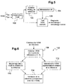
- the Figure 5 illustrates very generally how the device of the invention is implemented.
- the current VGM is constructed periodically, for example once a day or once a week, under stable conditions (slow sinus rhythm, preferably at night), then stored and compared to a reference VGM created at initialization. therapy, and possibly updated in case of alert or decompensation, or manually by the practitioner during a follow-up visit for example.
- a VGM is constructed (block 100).
- one (or more) reference VGM (s) is (are) constituted (block 102, detailed in Figure 8) and stored in memory (block 104).
- a current VGM is constructed and compared to the stored reference (block 106) to deduce an indicator of the long-term evolution of the patient's condition (remodeling, inverse remodeling). or non-progressive state) and / or the sudden onset of a serious phenomenon such as probe rupture or ischemia.
- the Figure 6 illustrates the creation of a reference VGM (block 102 of Figure 5).
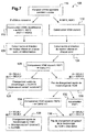
- the Figure 7 illustrates the sequence of the various operations of the current VGM test (block 106 of the Figure 5 ) performed at regular intervals, for example every day.
- the first step (block 116) is the inhibition of any stimulation by the device, so as to let a spontaneous rhythm be expressed during a predetermined number x of cycles.
- the device builds the current VGM (block 122) and determines the norm and the direction of the velocity vector at each point of this VGM (block 124), in the same way as at blocks 118 and 120 corresponding to the reference VGMs.
- the next step (block 126) consists in calculating the descriptors C (correlation coefficients between the norms of the velocity vectors) and ⁇ (average angle between the velocity vectors) representative of the comparison between the current VGM and the reference VGM REF1.
- the descriptors C and ⁇ are calculated (block 134) in the same way as in block 126, but this time by comparing the current VGM with the reference VGM REF2.
- the width of the QRS complex of the current EGM (this width being calculated as the time elapsed between the beginning and end of the detected depolarization ), or one or more parameters derived from an endocardial acceleration signal (EA), or also the interventricular conduction time.
- EA endocardial acceleration signal
Abstract
Le dispositif opère par analyse morphologique comparative de signaux de dépolarisation recueillis en rythme spontané sur des voies respectives distinctes, avec deux composantes temporelles combinées (122) en une unique caractéristique 2D paramétrique de vectogramme VGM. Des moyens d'analyse historique évaluent la variation au cours du temps d'un paramètre descripteur du VGM courant par rapport à un VGM de référence antérieur mémorisé. Cette variation est comparée (126, 134) à des seuils prédéterminés (SEUIL1, SEUIL2) pour diagnostiquer l'apparition d'un remodelage ou remodelage inverse chez le patient, et/ou détecter une rupture de sonde ou la survenue d'une ischémie. Le paramètre descripteur est fonction du vecteur vitesse du VGM, la comparaison portant sur un coefficient de corrélation (C) entre les normes des vecteurs vitesse respectifs du VGM courant et du VGM de référence, et sur l'angle moyen (¸) entre ces vecteurs vitesse respectifs.The device operates by comparative morphological analysis of depolarization signals collected in spontaneous rhythm on distinct respective pathways, with two combined temporal components (122) into a single parametric 2D Vectogram VGM characteristic. Historical analysis means evaluate the variation over time of a current VGM descriptor parameter with respect to a stored prior reference VGM. This variation is compared (126, 134) with predetermined thresholds (THRESHOLD1, THRESHOLD2) to diagnose the occurrence of remodeling or inverse remodeling in the patient, and / or to detect a rupture of the probe or the occurrence of ischemia. The descriptor parameter is a function of the velocity vector of the VGM, the comparison relating to a correlation coefficient (C) between the norms of the respective velocity vectors of the current VGM and the reference VGM, and on the mean angle (¸) between these vectors. respective speed.
Description
L'invention concerne les "dispositifs médicaux implantables actifs" tels que définis par la Directive 90/385/CEE du 20 juin 1990 du Conseil des communautés européennes, plus précisément les implants permettant de surveiller en continu le rythme cardiaque et délivrer si nécessaire au coeur des impulsions électriques de stimulation, de resynchronisation et/ou de défibrillation en cas de trouble du rythme détecté par le dispositif.The invention relates to "active implantable medical devices" as defined by the Council of European Communities Directive 90/385 / EEC of 20 June 1990, more specifically implants for continuously monitoring the heart rate and delivering if necessary to the heart. electrical pacing, resynchronization and / or defibrillation pulses in case of rhythm disturbance detected by the device.
La stimulation antibradycardique implique la surveillance des potentiels électriques de dépolarisation du myocarde, et la délivrance contrôlée d'impulsions à l'oreillette et/ou au ventricule. Dans le cas d'une resynchronisation cardiaque, la stimulation doit être appliquée conjointement aux deux ventricules.The bradycardia pacing involves monitoring the electrical potentials of depolarization of the myocardium, and the controlled delivery of impulses to the atrium and / or ventricle. In the case of cardiac resynchronization, the stimulation should be applied together with both ventricles.
L'invention sera décrite plus précisément dans le cadre d'un implant permettant de délivrer une thérapie de resynchronisation, dite "CRT" (Cardiac Resynchronization Therapy) ou "BVP" (Bi-Ventricular Pacing), consistant à surveiller en continu le rythme cardiaque et délivrer si nécessaire au coeur des impulsions électriques permettant de stimuler de façon conjointe et permanente les ventricules gauche et droit afin de resynchroniser ces derniers.The invention will be described more specifically in the context of an implant for delivering a resynchronization therapy, called "CRT" ( Cardiac Resynchronization Therapy ) or "BVP" ( Bi-Ventricular Pacing ), consisting of continuous monitoring of the heart rate and if necessary deliver to the heart of electrical impulses to stimulate joint and permanent left ventricles and right to resynchronize them.
Ce cas particulier n'est toutefois pas limitatif de l'invention qui, par un certain nombre de ses aspects, est applicable également à des dispositifs de type "simple chambre" où la détection/stimulation ne concernent que le ventricule droit, ou "double chambre" où la détection/stimulation ne concernent que le ventricule droit et l'oreillette droite.This particular case is however not limiting of the invention which, by a certain number of its aspects, is also applicable to devices of the "single chamber" type where the detection / stimulation only concern the right ventricle, or "double" chamber "where the detection / stimulation concerns only the right ventricle and the right atrium.
Un stimulateur CRT est divulgué par exemple dans le
Ce dispositif CRT inclut en outre un mode de fonctionnement en stimulateur "double chambre" classique, où le dispositif surveille l'activité ventriculaire après un événement auriculaire spontané (onde P) ou stimulé (impulsion A) et déclenche une stimulation du ventricule droit (impulsion V) si aucune activité spontanée ventriculaire (onde R) n'a été détectée à l'issue d'un délai dit "délai atrioventriculaire" ou "délai auriculo-ventriculaire" (DAV ou AVD).This CRT device further includes a conventional "dual chamber" stimulator mode of operation, wherein the device monitors ventricular activity after a spontaneous (P-wave) or paced (A-pulse) atrial event and triggers a right ventricular (impulse) stimulation. V) if no spontaneous ventricular activity (R-wave) was detected after a delay called "atrioventricular delay" or "atrioventricular delay" (AVD or AVD).
L'invention concerne plus particulièrement le suivi sur le long terme de l'état cardiaque du patient et de la manière dont évolue cet état, notamment pour diagnostiquer chez celui-ci l'apparition du phénomène dénommé "remodelage cardiaque", qui peut être défini comme l'ensemble des modifications du coeur engendrées en réponse à une pathologie, et qui est généralement associé à un plus mauvais pronostic.The invention relates more particularly to the long-term monitoring of the patient's cardiac state and how this state evolves, in particular to diagnose in it the appearance of the phenomenon called "cardiac remodeling", which can be defined as the set of changes in the heart generated in response to a pathology, and which is generally associated with a worse prognosis.
En effet, les modifications cliniques pouvant être asymptomatiques, il est courant que le patient adapte inconsciemment son activité à son état clinique : les premières crises d'insuffisance cardiaque apparaissant à l'effort, ceci conduit le patient à réduire son activité pour éviter la survenue de telles crises. Ensuite, les symptômes n'apparaissent plus car le patient a modifié son comportement pour les éviter, mais la pathologie continue à progresser.Indeed, the clinical changes can be asymptomatic, it is common that the patient unconsciously adapts its activity to its clinical state: the first attacks of heart failure appearing in the effort, this leads the patient to reduce its activity to avoid the occurrence such crises. Then, the symptoms do not appear anymore because the patient has modified his behavior to avoid them, but the pathology continues to progress.
Le remodelage se manifeste à la longue par une augmentation du volume du ventricule gauche, avec dégradation de la fraction d'éjection et du régime des pressions intraventriculaires du fait de la baisse de contractilité et/ou de pressions trop élevées en aval, et in fine par une diminution du débit cardiaque entrainant de graves conséquences sur l'organisme lorsque progresse l'insuffisance cardiaque. Et ce n'est que lorsque cette insuffisance cardiaque gênera le patient même au repos qu'il ira consulter ou, dans les cas extrêmes, devra être hospitalisé en urgence.The remodeling is manifested in the long term by an increase in the volume of the left ventricle, with degradation of the ejection fraction and the regime of the intraventricular pressures due to the decrease of contractility and / or too high pressures downstream, and in fine by a decrease in cardiac output with serious consequences for the body when heart failure progresses. And it is only when this heart failure disturbs the patient even at rest that he will consult or, in extreme cases, will be hospitalized urgently.
En résumé, du fait de l'auto-adaptation l'absence de symptômes ressentis introduit un retard important entre le début des modifications cliniques et le diagnostic de ces modifications, souvent trop tardif.In summary, because of the self-adaptation the absence of symptoms felt introduces a significant delay between the beginning of clinical changes and the diagnosis of these changes, often too late.
En stimulant de façon contrôlée les deux ventricules, la thérapie CRT permet d'optimiser le cycle contraction/relaxation avec un bénéfice direct facilitant le travail du coeur, ce qui peut permettre de stabiliser le phénomène de remodelage et même de le contrer ("remodelage inverse"), avec pour le patient un meilleur pronostic.By stimulating the two ventricles in a controlled way, CRT therapy optimizes the contraction / relaxation cycle with a direct benefit facilitating the work of the heart, which can help stabilize the remodeling phenomenon and even counteract it ("reverse remodeling"). "), with for the patient a better prognosis.
Le but principal de l'invention est de proposer un moyen de diagnostic incorporé à un stimulateur (CRT ou autre) qui permette d'assurer un suivi régulier de l'état du patient, par exemple quotidiennement, en particulier pour surveiller l'évolution d'un remodelage cardiaque (délétère) ou d'un remodelage inverse (bénéfique). Cette surveillance devra être suffisamment précoce pour pouvoir prendre au plus vite les mesures appropriées - par exemple une modification du paramétrage de la thérapie, ou la substitution à cette thérapie d'une autre thérapie si elle n'est pas efficace -, évitant ainsi le déclenchement imprévu d'une crise à brève ou moyenne échéance. Et en cas d'aggravation soudaine détectée, il sera possible d'alerter le médecin sans délai, par exemple par télétransmission d'un message à un site distant de télésurveillance.The main aim of the invention is to propose a diagnostic means incorporated into a stimulator (CRT or other) which makes it possible to regularly monitor the state of the patient, for example daily, in particular to monitor the evolution of cardiac remodeling (deleterious) or inverse remodeling (beneficial). This monitoring should be early enough to be able to take the appropriate measures as soon as possible - for example, to change the setting of the therapy, or to substitute this therapy for another therapy if it is not effective - thus avoiding triggering. unforeseen crisis in the short or medium term. And in case of sudden aggravation detected, it will be possible to alert the doctor without delay, for example by teletransmission of a message to a remote remote monitoring site.
La technique de référence pour évaluer sur le long terme l'évolution de l'état cardiaque du patient, et donc pour déterminer l'efficacité d'une thérapie et ajuster éventuellement les paramètres de stimulation, est l'écho-cardiographie avec mesure du volume ventriculaire et estimation des délais caractéristiques de la systole, en particulier du temps d'ouverture de la valve aortique. Cette procédure doit toutefois être mise en oeuvre en milieu hospitalier et par un personnel qualifié, elle est longue et coûteuse et ne peut pas être appliquée aussi souvent que cela serait utile ou nécessaire sans interférer avec la vie quotidienne du patient.The standard technique for evaluating the long-term evolution of the patient's cardiac condition, and therefore for determining the effectiveness of a therapy and possibly adjusting the stimulation parameters, is echo-cardiography with volume measurement. ventricular and estimation of the characteristic systolic delays, in particular the opening time of the aortic valve. However, this procedure must be performed in hospitals and by qualified personnel, is time-consuming and costly and can not be applied as often as would be useful or necessary without interfering with the patient's daily life.
Des techniques d'analyse automatique à partir du dispositif implanté ont également été proposées, par exemple par le
Le
Le
Le
Le but de l'invention est de proposer un dispositif de type stimulateur cardiaque implantable pourvu de moyens de diagnostic du remodelage cardiaque qui puissent pallier les inconvénients précités, en permettant en particulier :
- d'éviter des examens longs et coûteux par échographie cardiaque, qui ne fournissent qu'un diagnostic tardif, souvent plusieurs mois après l'implantation ;
- d'évaluer de façon précoce et robuste le remodelage du patient afin de réajuster en conséquence les paramètres de stimulation ;
- de mettre en place des alertes précoces en cas de risques de décompensation aggravée ou d'ischémie, pour prévenir les hospitalisations et modifier en temps utiles les thérapies et traitements ; et
- de façon générale, de s'assurer de la bonne délivrance et de l'efficacité de la thérapie appliquée.
- to avoid long and expensive exams by echocardiography, which provide only a late diagnosis, often several months after implantation;
- Evaluate the remodeling of the patient early and robustly in order to readjust the stimulation parameters accordingly;
- to set up early warnings in case of risks of aggravated decompensation or ischemia, to prevent hospitalizations and to modify therapies and treatments in good time; and
- in general, to ensure the proper delivery and effectiveness of the applied therapy.
Un autre but de l'invention est, en complément ou en variante d'un diagnostic d'un remodelage ou remodelage inverse se manifestant par des variations lentes, de pouvoir détecter des phénomènes à apparition brusque tels qu'ischémie ou déplacement de sonde, susceptibles de mettre gravement en danger le patient, ceci de manière à générer sans délai une alerte correspondante.Another object of the invention is, in addition to or as an alternative to a diagnosis of remodeling or inverse remodeling manifesting itself by slow variations, of being able to detect phenomena at onset. abrupt, such as ischemia or sensor displacement, which could seriously endanger the patient, so as to generate a corresponding alert without delay.
Plus précisément, l'invention propose un dispositif comprenant, de manière en elle-même connue :
- des moyens de stimulation contrôlée du coeur ;
- des moyens de détection de signaux de dépolarisation ventriculaire et/ou auriculaire ; et
- des moyens d'analyse morphologique, aptes à comparer entre eux des signaux de dépolarisation recueillis sur une même voie à des instants distincts.
- controlled stimulation means of the heart;
- means for detecting ventricular and / or atrial depolarization signals; and
- means of morphological analysis, able to compare depolarization signals collected on the same path at different times.
De façon caractéristique de l'invention, les moyens d'analyse morphologique comprennent :
- des moyens aptes à inhiber les moyens de stimulation contrôlée ;
- des moyens aptes à recueillir concurremment sur des voies respectives distinctes, au cours d'un cycle cardiaque en rythme spontané, au moins deux signaux EGM d'électrogramme endocavitaire et en dériver au moins deux composantes temporelles distinctes respectives ; et
- des moyens aptes à combiner les au moins deux composantes temporelles en au moins une caractéristique 2D paramétrique représentative dudit cycle cardiaque, à partir des variations de l'une des composantes temporelles en fonction de l'autre ; et
- des moyens d'analyse de la caractéristique 2D, aptes à dériver de la caractéristique 2D, ou d'une moyenne de caractéristiques 2D recueillies sur des cycles cardiaques successifs, au moins un paramètre descripteur intrinsèque représentatif de la caractéristique 2D ;
- des moyens d'analyse historique, aptes à évaluer périodiquement la variation au cours du temps dudit au moins un paramètre descripteur intrinsèque d'une caractéristique 2D courante par rapport à une caractéristique 2D de référence antérieure mémorisée par le dispositif ; et
- des moyens de comparaison, aptes à comparer à au moins un seuil prédéterminé la variation évaluée par les moyens d'analyse historique, et à déclencher sélectivement une alerte en fonction du résultat de la comparaison.
- means capable of inhibiting the controlled stimulation means;
- means capable of concurrently collecting on respective separate pathways, during a spontaneous rhythm cardiac cycle, at least two endocavitary electrogram EGM signals and deriving at least two respective distinct temporal components therefrom; and
- means capable of combining the at least two temporal components into at least one parametric 2D characteristic representative of said cardiac cycle, based on the variations of one of the temporal components as a function of the other; and
- means for analyzing the 2D characteristic, able to derive from the 2D characteristic, or an average of 2D characteristics collected on successive cardiac cycles, at least one intrinsic descriptor parameter representative of the 2D characteristic;
- historical analysis means, capable of periodically evaluating the variation over time of said at least one intrinsic descriptor parameter of a current 2D characteristic with respect to an earlier reference 2D characteristic stored by the device; and
- comparison means, able to compare the variation evaluated by the historical analysis means with at least one predetermined threshold, and to selectively trigger an alert based on the result of the comparison.
Selon diverses caractéristiques subsidiaires avantageuses :
- les moyens d'analyse historique sont des moyens aptes à évaluer quotidiennement ladite variation au cours du temps du au moins un paramètre descripteur intrinsèque ;
- ledit au moins un paramètre descripteur intrinsèque est un paramètre fonction du vecteur vitesse de la caractéristique 2D, considéré en une pluralité de points respectifs (Pi) de cette caractéristique ;
- ce paramètre peut notamment comprendre la norme du vecteur vitesse, avec des moyens d'analyse historique aptes à calculer un coefficient de corrélation entre les normes des vecteurs vitesse respectifs de la caractéristique 2D courante et de la caractéristique 2D de référence ;
- ce paramètre peut également comprendre l'orientation du vecteur vitesse, avec des moyens d'analyse historique aptes à calculer l'angle moyen entre les vecteurs vitesse respectifs de la caractéristique 2D courante et de la caractéristique 2D de référence ;
- les moyens de comparaison peuvent comprendre en particulier : des moyens aptes à comparer i) l'angle moyen entre vecteurs vitesse à un premier seuil et ii) le coefficient de corrélation entre normes des vecteurs vitesse à un second seuil ; et des moyens aptes à déclencher ladite alerte lorsqu'à la fois i) l'angle moyen entre vecteurs vitesse est supérieur au premier seuil ou ii) le coefficient de corrélation entre normes des vecteurs vitesse est inférieur au second seuil ;
- les moyens d'analyse morphologique sont en outre aptes, en l'absence de déclenchement de ladite alerte par les moyens de comparaison, à actualiser ledit au moins un paramètre descripteur intrinsèque de la caractéristique 2D de référence ;
- le dispositif comprend en outre des moyens de diagnostic de remodelage ou de remodelage inverse mettant en oeuvre lesdits moyens d'analyse morphologique, ladite alerte déclenchée par les moyens de comparaison étant une alerte de survenue d'un remodelage ou remodelage inverse chez le patient ;
- le dispositif comprend en outre des moyens de détection de rupture de sonde ou de diagnostic d'ischémie mettant en oeuvre lesdits moyens d'analyse morphologique, ladite alerte déclenchée par les moyens de comparaison étant une alerte de rupture de sonde ou de survenue d'ischémie chez le patient.
- the means of historical analysis are means able to evaluate daily said variation over time of the at least one intrinsic descriptor parameter;
- said at least one intrinsic descriptor parameter is a function parameter of the velocity vector of the 2D characteristic, considered at a plurality of respective points (Pi) of this characteristic;
- this parameter can notably comprise the norm of the velocity vector, with historical analysis means capable of calculating a coefficient of correlation between the norms of the respective velocity vectors of the current 2D characteristic and the reference 2D characteristic;
- this parameter can also include the orientation of the velocity vector, with historical analysis means able to calculate the average angle between the respective velocity vectors of the current 2D characteristic and the reference 2D characteristic;
- the comparison means may comprise in particular: means capable of comparing i) the average angle between velocity vectors at a first threshold and ii) the coefficient of correlation between norms of velocity vectors at a second threshold; and means adapted to trigger said alert when both i) the average angle between speed vectors is greater than the first threshold or ii) the correlation coefficient between speed vector norms is less than the second threshold;
- the morphological analysis means are further able, in the absence of triggering said alert by the comparison means, to update said at least one intrinsic descriptor parameter of the reference 2D characteristic;
- the device further comprises means for diagnosis of remodeling or inverse remodeling using said morphological analysis means, said alert triggered by the means of comparison being an alert for the occurrence of remodeling or remodeling in the patient;
- the device further comprises probe rupture detection or ischemia diagnostic means using said morphological analysis means, said alert triggered by the means of comparison being an alert of rupture of probe or occurrence of ischemia in the patient.
Dans une forme de réalisation particulière, les signaux EGM recueillis concurremment sur des voies respectives distinctes comprennent :
- un signal EGM far-field unipolaire recueilli entre i) une électrode proximale ou distale ou le cas échéant une électrode intermédiaire ou un bobinage de défibrillation d'une sonde ventriculaire et ii) un boitier métallique de générateur du dispositif,
ou bien entre i) une première électrode proximale, ou électrode distale ou bobinage de défibrillation et ii) et une seconde électrode proximale, ou une électrode distale ou le cas échéant une électrode intermédiaire ou un bobinage de défibrillation, respectivement de deux sondes ventriculaires distinctes situées toutes deux dans un même ventricule,
ou bien entre i) une première électrode proximale, ou électrode distale ou bobinage de défibrillation et ii) et une seconde électrode proximale, ou une électrode distale ou une électrode intermédiaire, respectivement d'une sonde ventriculaire droite et d'une sonde ventriculaire gauche ; et - un signal EGM near-field bipolaire recueilli entre i) une électrode distale et ii) une électrode proximale d'une sonde ventriculaire,
ou bien entre i) un bobinage de défibrillation et ii) une électrode distale ou proximale de ladite sonde ventriculaire,
ou bien entre i) une électrode distale et ii) une électrode intermédiaire d'une sonde ventriculaire gauche
ou bien entre i) une électrode proximale et ii) une électrode intermédiaire de ladite sonde ventriculaire gauche
ou bien entre deux électrodes intermédiaires de ladite sonde ventriculaire gauche.
- a unipolar far-field EGM signal collected between i) a proximal or distal electrode or optionally an intermediate electrode or a defibrillation coil of a ventricular probe and ii) a metal generator housing of the device,
or between i) a first proximal electrode, or distal electrode or defibrillation coil and ii) and a second proximal electrode, or a distal electrode or optionally an intermediate electrode or a defibrillation coil, respectively of two distinct ventricular probes located both in the same ventricle,
or between i) a first proximal electrode, or distal electrode or defibrillation coil and ii) and a second proximal electrode, or a distal electrode or an intermediate electrode, respectively of a right ventricular lead and a left ventricular lead; and - a bipolar near-field EGM signal collected between i) a distal electrode and ii) a proximal electrode of a ventricular probe,
or between i) a defibrillation coil and ii) an electrode distal or proximal to said ventricular probe,
or between i) a distal electrode and ii) an intermediate electrode of a left ventricular probe
or between i) a proximal electrode and ii) an intermediate electrode of said left ventricular probe
or between two intermediate electrodes of said left ventricular probe.
On va maintenant décrire un exemple de mise en oeuvre de la présente invention, en référence aux dessins annexés où les mêmes références désignent d'une figure à l'autre des éléments identiques ou fonctionnellement semblables.
- La
Figure 1 est une vue générale montrant un dispositif CRT avec son générateur et des sondes cardiaques droite et gauche implantées dans le coeur. - La
Figure 2 est un exemple de signaux EGM obtenus sur des voies respectivement ventriculaire bipolaire et ventriculaire unipolaire de l'une des sondes de laFigure 1 . - La
Figure 3 illustre la manière de combiner entre eux les signaux bipolaire et unipolaire recueillis dans une même cavité ventriculaire pour construire une caractéristique bidimensionnelle de type vectogramme, indépendante du temps. - La
Figure 4 est un exemple de vectogramme échantillonné obtenu pour un cycle cardiaque échantillonné à 128 Hz, avec représentation des vecteurs vitesse en divers points successifs. - La
Figure 5 est un schéma de principe illustrant la mise en oeuvre de l'invention. - La
Figure 6 est un diagramme présentant la séquence d'étapes exécutées lors de l'élaboration préalable des références. - La
Figure 7 est un diagramme présentant la séquence d'étapes exécutées lors du suivi du patient, pour déterminer l'évolution de son état, notamment l'apparition d'un remodelage ou remodelage inverse.
- The
Figure 1 is a general view showing a CRT device with its generator and right and left heart probes implanted in the heart. - The
Figure 2 is an example of EGM signals obtained on bipolar and ventricular unipolar ventricular respectively of one of the probes of theFigure 1 . - The
Figure 3 illustrates how to combine the bipolar and unipolar signals collected in the same ventricular cavity together to construct a two-dimensional characteristic of the vectogram type, independent of time. - The
Figure 4 is an example of a sampled vectogram obtained for a cardiac cycle sampled at 128 Hz, with representation of velocity vectors at various successive points. - The
Figure 5 is a block diagram illustrating the implementation of the invention. - The
Figure 6 is a diagram showing the sequence of steps performed during the preliminary development of the references. - The
Figure 7 is a diagram showing the sequence of steps performed during the follow-up of the patient, to determine the evolution of his state, in particular the appearance of a remodeling or inverse remodeling.
On va maintenant décrire un exemple de réalisation du dispositif de l'invention.An embodiment of the device of the invention will now be described.
En ce qui concerne ses aspects logiciels, l'invention peut être mise en oeuvre par une programmation appropriée du logiciel de commande d'un stimulateur connu comprenant des moyens d'acquisition d'un signal fourni par des sondes endocavitaires et/ou par un ou plusieurs capteurs implantés.With regard to its software aspects, the invention can be implemented by appropriate programming of the control software of a known pacemaker comprising means for acquiring a signal provided by endocavity probes and / or by one or several implanted sensors.
L'invention peut notamment être appliquée aux dispositifs implantables tels que ceux des familles Reply, Paradym, Intensia, Paradym RF et Platinium, produits et commercialisés par Sorin CRM, Clamart, France.The invention can notably be applied to implantable devices such as those of the Reply, Paradym, Intensia, Paradym RF and Platinum families , produced and marketed by Sorin CRM, Clamart, France.
Il s'agit de dispositifs à microprocesseur programmable comportant des circuits pour recevoir, mettre en forme et traiter des signaux électriques recueillis par des électrodes implantées, et délivrer des impulsions de stimulation à ces électrodes. Il est possible d'y transmettre par télémétrie des logiciels qui seront conservés en mémoire et exécutés pour mettre en oeuvre les fonctions de l'invention qui seront décrites ci-dessous. L'adaptation de ces appareils à la mise en oeuvre des fonctions de l'invention est à la portée de l'homme du métier, et elle ne sera pas décrite en détail.These are programmable microprocessor devices having circuits for receiving, shaping and processing electrical signals collected by implanted electrodes, and deliver stimulation pulses to these electrodes. It is possible to transmit there by telemetry software which will be stored in memory and executed to implement the functions of the invention which will be described below. The adaptation of these devices to the implementation of the functions of the invention is within the abilities of those skilled in the art, and it will not be described in detail.
Le procédé de l'invention est mis en oeuvre par des moyens principalement logiciels, grâce à des algorithmes appropriés exécutés automatiquement et de façon récurrente par un microcontrôleur ou un processeur numérique de signal. Pour la clarté de l'exposé, les divers traitements appliqués sont décomposés et schématisés par un certain nombre de blocs fonctionnels distincts, mais cette représentation n'a toutefois qu'un caractère illustratif, ces circuits comprenant des éléments communs et correspondant en pratique à une pluralité de fonctions globalement exécutées par un même logiciel.The method of the invention is implemented by mainly software means, thanks to appropriate algorithms automatically and recurrently executed by a microcontroller or a digital signal processor. For the sake of clarity, the various treatments applied are decomposed and schematized by a number of distinct functional blocks, but this representation is however only of an illustrative nature, these circuits comprising common elements and corresponding in practice to a plurality of functions globally executed by the same software.
La
Pour permettre la stimulation biventriculaire, notamment afin de rétablir la synchronisation entre les deux ventricules, le dispositif est pourvu d'une troisième sonde 28, par exemple une sonde disposée dans le réseau coronaire, comportant une ou plusieurs électrodes 30, 32 disposées au voisinage du ventricule gauche 34. Outre les électrodes distale et proximale 30, 32 illustrées, la sonde gauche peut également comporter une ou plusieurs électrodes intermédiaires située(s) dans une position médiane entre les électrodes 30 et 32. Il est ainsi possible d'assurer la stimulation concomitante, ou avec un léger décalage temporel contrôlé (délai interventriculaire DW), des deux ventricules droit et gauche pour rétablir la synchronisation entre ces deux cavités et améliorer l'hémodynamique générale du patient (on ajoutera que dans le cas d'une sonde gauche multi-électrodes on peut également appliquer une stimulation multisite à gauche, pour traiter un trouble du synchronisme intra-ventriculaire).To allow biventricular pacing, in particular to restore synchronization between the two ventricles, the device is provided with a
La sonde ventriculaire droite 12 peut également être pourvue d'un bobinage (coil) ventriculaire 36 formant électrode de défibrillation et permettant aussi de recueillir un signal endocavitaire (ce bobinage pouvant également remplacer l'électrode proximale ring 18).The
En ce qui concerne spécifiquement la stimulation du ventricule gauche, il est possible d'utiliser une configuration bipolaire (entre les deux électrodes 30 et 32 de la sonde 28) ou unipolaire (entre l'une des électrodes 30 ou 32 et le boitier can) du générateur 10. Les deux "vecteurs de stimulation" correspondants sont référencés 38 et 40 sur la
On va maintenant exposer, dans ce contexte, les aspects spécifiques de l'invention.In this context, the specific aspects of the invention will now be explained.
Le but de l'invention est, comme indiqué en introduction, de surveiller l'évolution sur le long terme de la morphologie des signaux cardiaques recueillis en rythme spontané du patient (c'est-à-dire en l'absence de toute stimulation appliquée par le dispositif), par exemple par une évaluation quotidienne, pour détecter :
- des variations lentes de cette morphologie, qui révèleraient notamment l'apparition d'un remodelage (avec dilatation des ventricules, délétère pour le patient) ou d'un remodelage inverse (avec diminution du volume ventriculaire, bénéfique pour le patient), et/ou
- des variations brusques, causés par des phénomènes à apparition soudaine, tels qu'ischémie ou déplacement de sonde, susceptibles de mettre gravement en danger le patient, afin de générer sans délai une alerte.
- slow variations of this morphology, which would reveal in particular the appearance of a remodeling (with dilation of the ventricles, deleterious for the patient) or of an inverse remodeling (with decrease of the ventricular volume, beneficial for the patient), and / or
- abrupt changes, caused by sudden onset phenomena, such as ischemia or sensor displacement, which could seriously endanger the patient, in order to generate an alert without delay.
Plus précisément, pour pallier les inconvénients des techniques connues qui ont été rappelées en introduction, l'invention propose de combiner deux signaux d'électrogramme endocavitaire (EGM) recueillis en rythme spontané du patient, en particulier des signaux issus de la même cavité ventriculaire, par exemple du ventricule droit.More specifically, in order to overcome the disadvantages of the known techniques which have been recalled in the introduction, the invention proposes to combine two endocavity electrogram (EGM) signals collected in rhythm. spontaneous patient, particularly signals from the same ventricular cavity, for example the right ventricle.
Pour que la condition de rythme spontané soit respectée, l'analyse des signaux est effectuée pendant un intervalle de temps où aucune stimulation n'est délivrée (dans le cas d'une stimulation à la demande), ou bien pendant une brève période d'inhibition forcée de la stimulation par le dispositif.In order for the spontaneous rhythm condition to be respected, the signal analysis is performed during a time interval when no stimulation is delivered (in the case of demand stimulation), or for a brief period of time. Forced inhibition of stimulation by the device.
Les EGMs recueillis à cet effet dans le ventricule droit peuvent comprendre par exemple (voir
- une composante ventriculaire droite Vbip, dérivée d'un signal EGM near-field bipolaire recueilli entre l'électrode distale 16 et l'électrode proximale 18 de la sonde ventriculaire droite 12, et
- une autre composante ventriculaire droite Vuni, dérivée d'un signal EGM far-field unipolaire recueilli entre le bobinage de défibrillation 36 de la sonde ventriculaire droite 12 et le boitier métallique du générateur 10.
- a right ventricular component Vbip, derived from a bipolar near-field EGM signal collected between the
distal electrode 16 and theproximal electrode 18 of theright ventricular probe 12, and - another Vuni right ventricular component , derived from a unipolar far-field EGM signal collected between the
defibrillation coil 36 of theright ventricular probe 12 and the metal housing of thegenerator 10.
La
D'autres configurations peuvent être utilisées, à partir de signaux de type far-field (par exemple entre l'une des électrodes 16 ou 18 et le boitier 10) et de type near-field (entre deux électrodes de la même sonde ventriculaire).Other configurations may be used, from far-field signals (for example between one of the
Cette configuration (signaux issus des cavités droites) n'est toutefois pas limitative. Dans certains cas, par exemple pour un patient souffrant d'un bloc de branche gauche (LBBB, Left Bundle Branch Block) sans problème de conduction à droite, l'effet d'un remodelage ne sera pas apparent sur les signaux recueillis au niveau des cavités droites. Dans un tel cas, il conviendra d'analyser des composantes dérivées par exemple d'un signal bipolaire ventriculaire gauche et d'un signal interventriculaire, ou encore d'un signal bipolaire gauche et d'un signal unipolaire gauche. La composante bipolaire serait alors recueillie par exemple entre les électrodes 30 et 32 de la sonde ventriculaire gauche 28 (comme référencé en 38), et la composante unipolaire entre l'électrode tip 30 (ou l'électrode ring 32) et le boitier can du générateur 10, comme référencé en 40. En variante, la composante unipolaire peut être également recueillie entre l'électrode tip 30 (ou l'électrode ring 32) de la sonde ventriculaire gauche 28 et le bobinage coil 36 de la sonde ventriculaire droite 12, comme référencé en 42.This configuration (signals from the right cavities) is however not limiting. In some cases, for example for a patient suffering from a left bundle branch block (LBBB ) without right conduction problem, the effect of a remodeling will not be apparent on the signals collected at the level of straight cavities. In such a case, it will be necessary to analyze components derived for example from a left ventricular bipolar signal and an interventricular signal, or from a left bipolar signal and a left unipolar signal. The bipolar component would then be collected, for example, between the
On constate que sur le long terme, si l'on effectue par exemple des comparaisons au moment de l'implantation, trois mois après l'implantation et un an après l'implantation), la forme des signaux évolue au cours du temps, mais que dans certains cas, ou chez certains patients, le signal unipolaire Vuni n'apporte pas vraiment d'information sur cette évolution dans le temps, tandis que le signal bipolaire Vbip contient des informations beaucoup plus significatives. Inversement, dans d'autres cas, l'évolution est très tardive sur le signal bipolaire Vbip et c'est la voie unipolaire Vuni (entre le bobinage coil 36 et le boitier can 10 du générateur) qui peut donner l'information recherchée, de façon beaucoup plus précoce et discriminante.It can be seen that in the long term, if for example comparisons are made at the time of implantation, three months after implantation and one year after implantation, the shape of the signals changes over time, but that in some cases, or in some patients, the Vuni unipolar signal does not really provide information on this evolution over time, while the Vbip bipolar signal contains much more significant information. Conversely, in other cases, the evolution is very late on the bipolar signal Vbip and it is the unipolar channel Vuni (between the
Pour pallier cet inconvénient, l'invention propose de combiner ces deux composantes bipolaire et unipolaire en une caractéristique unique contenant, de façon plus globale, toute l'information disponible afin de pouvoir procéder à une évaluation complète et robuste de l'état du patient au fil du temps.To overcome this drawback, the invention proposes to combine these two bipolar and unipolar components into a single characteristic containing, more generally, all the available information in order to be able to carry out a complete and robust evaluation of the patient's condition. over time.
Cette combinaison des deux signaux bipolaire et unipolaire est réalisée sous forme d'une "boucle cardiaque" ou "vectogramme" (VGM), qui est la représentation dans un espace à deux dimensions de l'un des deux signaux EGM (en ordonnée) par rapport à l'autre (en abscisse). Chaque cycle cardiaque est alors représenté par un vectogramme dans le plan {Vbip,Vuni} ainsi défini, vectogramme dont la géométrie (forme de la courbe) fait donc abstraction de la dimension temporelle - qui n'intervient que comme un paramètre décrivant la manière dont la courbe est parcourue.This combination of the two bipolar and unipolar signals is performed as a "cardiac loop" or "vectogram" (VGM), which is the representation in a two-dimensional space of one of the two EGM signals (ordinate) by relationship to the other (as abscissa). Each cardiac cycle is then represented by a vectogram in the plane { Vbip, Vuni } thus defined, a vectogram whose geometry (shape of the curve) thus abstracts from the temporal dimension - which intervenes only as a parameter describing the way in which the curve is traveled.
On soulignera que ce "vectogramme" (VGM), qui est obtenu à partir de signaux d'électrogramme (EGM) issu de sondes intracardiaques, ne doit pas être confondu avec le "vectocardiogramme" (VCG) qui est, lui, obtenu à partir de signaux d'électrocardiogramme (ECG) issu d'électrodes externes placées sur le thorax du patient.It should be emphasized that this "vectogram" (VGM), which is obtained from electrogram signals (EGM) from intracardiac probes, should not be confused with the "vectocardiogram" (VCG), which is obtained from of electrocardiogram (ECG) signals from external electrodes placed on the patient's thorax.
La construction d'un VGM et son analyse pour quantifier des données cardiaques sont décrites par exemple dans
L'analyse d'un VGM à des fins différentes de celles de l'invention a été déjà proposée notamment par le
Mais dans tous ces cas, il s'agit d'analyser un cycle cardiaque isolé, pour révéler une caractéristique propre à ce cycle (type d'arythmie, présence ou non d'une capture, artefact, etc.). Il ne s'agit jamais, comme dans la présente invention, d'effectuer une analyse historique visant à déterminer l'apparition de variations plus ou moins rapides, sur le long terme, de telle ou telle caractéristique du VGM, notamment à des fins de diagnostic d'un état évolutif du patient.But in all these cases, it is a question of analyzing an isolated cardiac cycle, to reveal a characteristic peculiar to this cycle (type of arrhythmia, presence or not of a capture, artifact, etc.). It is never a question, as in the present invention, of carrying out a historical analysis aimed at determining the appearance of more or less rapid variations, in the long term, of this or that characteristic of the VGM, in particular for the purposes of diagnosis of a progressive state of the patient.
Concrètement, comme illustré
Cette courbe est une courbe paramétrée par le temps, tracée à partir des variations de l'une des composantes temporelles (Vuni) en fonction de l'autre (Vbip). Elle constitue un vectogramme (VGM) représentatif du cycle cardiaque à analyser, et sera également désignée "caractéristique 2D paramétrique". Elle présente graphiquement la forme d'une boucle, le temps n'apparaissant plus que dans la manière dont la boucle est parcourue sur la durée du cycle.This curve is a curve parameterized by time, drawn from the variations of one of the temporal components ( Vuni ) as a function of the other ( Vbip ). It constitutes a representative vectogram (VGM) of the cardiac cycle to be analyzed, and will also be designated "parametric 2D characteristic". It graphically presents the shape of a loop, the time appearing only in the way the loop is traversed over the duration of the cycle.
On notera incidemment que l'analyse 'bidimensionnelle" ou "en deux dimensions" (2D) évoquée ici ne doit pas être entendue de manière en elle-même limitative. L'invention peut en effet s'appliquer aussi bien à une analyse dans un espace multidimensionnel d'ordre supérieur (3D ou plus), par extrapolation des enseignements de la présente description à une situation où des signaux EGM provenant d'une même cavité sont recueillis simultanément sur trois voies ou plus.Incidentally, the "two-dimensional" or "two-dimensional" (2D) analysis referred to here is not to be understood in a way that is in itself limiting: the invention can indeed be applied to an analysis in a Higher order multidimensional space (3D or greater), by extrapolation of the teachings of the present description to a situation where EGM signals from the same cavity are collected simultaneously on three or more channels.
En pratique, comme illustré
On a également représenté sur la
La caractéristique VGM recueillie est mémorisée sous forme d'une série de paramètres descripteurs basés sur les vecteurs vitesse en chaque point de la courbe et comprenant i) la norme du vecteur vitesse et ii) l'orientation du vecteur vitesse, c'est-à-dire l'angle qu'il fait par rapport à l'axe des abscisses du VGM.The collected VGM characteristic is stored as a series of descriptor parameters based on velocity vectors at each point of the curve and comprising i) the velocity vector standard and ii) the velocity vector orientation, i.e. say the angle that it does with respect to the abscissa axis of the VGM.
L'invention propose d'opérer une comparaison morphologique entre le VGM courant (mémorisé sous forme des valeurs des normes et des angles des vecteurs vitesse aux différents points d'échantillonnage) avec un VGM de référence (mémorisé sous forme de descripteurs homologues).The invention proposes to make a morphological comparison between the current VGM (stored in the form of the norm values and the angles of the velocity vectors at the different sampling points) with a reference VGM (stored in the form of homologous descriptors).
La comparaison entre ces deux VGMs consiste à quantifier leurs ressemblances à partir :
- du coefficient de corrélation C entre les normes des vecteurs vitesse respectifs du VGM courant et du VGM de référence, et
- de la valeur moyenne θ de l'angle que font entre eux les vecteurs vitesse respectifs du VGM courant et du VGM de référence.
- correlation coefficient C between the standards of the respective velocity vectors of the current VGM and the reference VGM, and
- the mean value θ of the angle between the respective velocity vectors of the current VGM and the reference VGM.
On peut considérer que les courbes se ressemblent, si C (qui reflète la corrélation entre les normes des vecteurs vitesse) est suffisamment grand et θ (qui reflète les écarts angulaires d'orientation) est suffisamment petit. Un simple seuil peut alors être défini pour chaque descripteur (SEUIL1 pour l'angle et SEUIL2 pour le coefficient de corrélation), afin de conclure sur la ressemblance des courbes :
- si θ est inférieur à SEUIL1 et C supérieur à SEUIL2, on considèrera que les courbes sont similaires,
- si θ est supérieur à SEUIL1 ou C est inférieur à SEUIL2, on considèrera que les courbes sont différentes.
- if θ is less than THRESHOLD1 and C greater than THRESHOLD2, we will consider that the curves are similar,
- if θ is greater than THRESHOLD1 or C is less than THRESHOLD2, we consider that the curves are different.
Un remodelage ou un remodelage inverse ne devraient pas modifier brusquement la morphologie des EGMs recueillis en rythme spontané. Si l'on trouve des courbes différentes, on peut donc penser qu'une anomalie est survenue.Remodeling or inverse remodeling should not abruptly alter the morphology of the spontaneously occurring EGMs. If we find different curves, we can think that an anomaly has occurred.
L'invention propose de détecter d'éventuels changements de cette morphologie des EGMs, que ces changements soient brusques ou qu'ils soient progressifs.The invention proposes to detect possible changes in this morphology of EGMs, whether these changes are abrupt or that they are progressive.
Dans le cas d'un changement à la fois brusque et important de morphologie, on peut considérer que le patient est en danger, ce changement révélant un phénomène grave tel qu'un déplacement de sonde, une ischémie, etc. Il est alors souhaitable de déclencher une alerte.In the case of a sudden and significant change in morphology, the patient may be considered to be in danger, this change revealing a serious phenomenon such as probe displacement, ischemia, etc. It is then desirable to trigger an alert.
Des changements progressifs, mais peu importants, de morphologie peuvent se présenter notamment après les premiers mois suivant l'implantation, et sont dus par exemple à la maturation des sondes. Aucune action particulière n'est à entreprendre dans ce cas.Gradual changes, but small, morphology may occur especially after the first months after implantation, and are due for example to the maturation of the probes. No special action is to be taken in this case.
En revanche, des changements dus à un remodelage ou à un remodelage inverse seront également progressifs, mais plus importants. Si l'on veut mettre en évidence ces phénomènes particuliers, il suffira de choisir des seuils appropriés, par exemple déterminés au préalable à partir d'une base d'apprentissage.On the other hand, changes due to remodeling or reverse remodeling will also be gradual, but more important. If we want to highlight these particular phenomena, it will suffice to choose appropriate thresholds, for example determined beforehand from a learning base.
La
Le VGM courant est construit périodiquement, par exemple une fois par jour ou une fois par semaine, dans des conditions stables (rythme sinusal lent, de préférence la nuit), pour être ensuite mémorisé et comparé à un VGM de référence créé à l'initialisation de la thérapie, et éventuellement mis à jour en cas d'alerte ou de décompensation, ou de façon manuelle par le praticien lors d'une visite de suivi par exemple.The current VGM is constructed periodically, for example once a day or once a week, under stable conditions (slow sinus rhythm, preferably at night), then stored and compared to a reference VGM created at initialization. therapy, and possibly updated in case of alert or decompensation, or manually by the practitioner during a follow-up visit for example.
À partir des EGMs bipolaire et unipolaire recueillis, un VGM est construit (bloc 100). Dans un premier temps, un (ou plusieurs) VGM(s) de référence est (sont) constitué(s) (bloc 102, détaillé Figure 8) et conservé(s) en mémoire (bloc 104). De la même façon, périodiquement, par exemple quotidiennement, un VGM courant est construit et comparé à la référence mémorisée (bloc 106) pour en déduire un indicateur de l'évolution sur le long terme de l'état du patient (remodelage, remodelage inverse ou état non évolutif) et/ou l'apparition soudaine d'un phénomène grave tel que rupture de sonde ou ischémie.From the bipolar and unipolar EGMs collected, a VGM is constructed (block 100). In a first step, one (or more) reference VGM (s) is (are) constituted (block 102, detailed in Figure 8) and stored in memory (block 104). In the same way, periodically, for example daily, a current VGM is constructed and compared to the stored reference (block 106) to deduce an indicator of the long-term evolution of the patient's condition (remodeling, inverse remodeling). or non-progressive state) and / or the sudden onset of a serious phenomenon such as probe rupture or ischemia.
La
Cette référence est créée à partir de plusieurs cycles cardiaques représentatifs (absence d'artefact, d'extrasystole, de fusion, etc.), par exemple x = 2 à 5 cycles cardiaques, pour chacun desquels le VGM est construit et le vecteur de paramètres descripteurs est calculé (bloc 108). Ces données sont ensuite moyennées (bloc 110) ou, en variante, l'un des cycles cardiaques le plus représentatif est sélectionné pour constituer la référence (bloc 112). À partir du VGM moyenné ou sélectionné, la référence est validée (bloc 114), en la comparant à chacun des cycles recueillis à l'étape 108, de manière à vérifier que l'écart entre cette référence et chacun des autres cycles reste dans des limites acceptables, ou en s'assurant qu'il reste dans ces limites pour un nombre suffisant, prédéterminé, de ces autres cycles.This reference is created from several representative cardiac cycles (absence of artefact, extrasystole, fusion, etc.), for example x = 2 to 5 cardiac cycles, for each of which the VGM is constructed and the parameter vector descriptors is calculated (block 108). These data are then averaged (block 110) or, alternatively, one of the most representative cardiac cycles is selected to constitute the reference (block 112). From the averaged or selected VGM, the reference is validated (block 114), comparing it with each of the cycles collected in
La
La première étape (bloc 116) est l'inhibition de toute stimulation par le dispositif, de manière à laisser s'exprimer un rythme spontané pendant un nombre prédéterminé x de cycles.The first step (block 116) is the inhibition of any stimulation by the device, so as to let a spontaneous rhythm be expressed during a predetermined number x of cycles.
Si aucun VGM de référence n'est disponible à ce stade, il convient de créer un ou plusieurs VGMs de référence correspondant à l'état du patient. Dans l'exemple illustré, on créera deux VGMs de référence REF1, REF2 :
- le VGM de référence REF1 sera destiné à mettre en évidence les changements brutaux de morphologie, résultant par exemple d'un déplacement de sonde ou de l'apparition d'une ischémie, tandis que
- le VGM de référence REF2 sera destiné à la mise en évidence des changements progressifs de morphologie liés à l'apparition éventuelle d'un remodelage ou remodelage inverse ; ce VGM sera déterminé une fois pour toutes et ne sera pas modifié automatiquement ensuite.
- the reference VGM REF1 will be intended to highlight the sudden changes in morphology, resulting for example from a displacement of the probe or the appearance of ischemia, while
- the reference VGM REF2 will be used to highlight progressive changes in morphology related to the eventual appearance of remodeling or reverse remodeling; this VGM will be determined once and for all and will not be changed automatically thereafter.
Les VGMs de référence REF1 et REF2 sont construits de la manière expliquée plus haut en référence à la
Si, à l'issue de l'étape 116 les références REF1 et REF2 sont disponibles en mémoire, alors le dispositif construit le VGM courant (bloc 122) et détermine la norme et la direction du vecteur vitesse en chaque point de ce VGM (bloc 124), de la même manière qu'aux blocs 118 et 120 correspondant aux VGMs de référence.If, at the end of
L'étape suivante (bloc 126) consiste à calculer les descripteurs C (coefficients de corrélation entre les normes des vecteurs vitesse) et θ (angle moyen entre les vecteurs vitesse) représentatifs de la comparaison entre le VGM courant et le VGM de référence REF1.The next step (block 126) consists in calculating the descriptors C (correlation coefficients between the norms of the velocity vectors) and θ (average angle between the velocity vectors) representative of the comparison between the current VGM and the reference VGM REF1.
Si la condition θ > SEUIL1 ou C < SEUIL2 est vérifiée (bloc 128) ceci signifie qu'il y a un changement brusque de morphologie est intervenu, et justifie le déclenchement d'une alerte, par exemple la télétransmission d'un message à un site distant afin d'alerter un médecin sur un phénomène tel que déplacement de sonde ou apparition d'une ischémie.If the condition θ> SEUIL1 or C <SEUIL2 is verified (block 128) this means that there is a sudden change in morphology has occurred, and justifies the triggering of an alert, for example the teletransmission of a message to a remote site to alert a doctor about a phenomenon such as probe displacement or the appearance of ischemia.
Si la condition précitée n'est pas vérifiée, c'est-à-dire si θ < SEUIL1 et C > SEUIL2 (bloc 130) on considère qu'il n'y a pas eu de changement rapide de la morphologie. Le VGM de référence REF1 est alors actualisé en le remplaçant par la valeur du VGM courant (bloc 132), et le dispositif cherche alors à mettre en évidence un changement progressif de morphologie qui pourrait révéler un remodelage ou remodelage inverse.If the above condition is not satisfied, that is, if θ <THRESH1 and C> SEUIL2 (block 130) it is considered that there has been no rapid change in morphology. The reference VGM REF1 is then updated by replacing it with the value of the current VGM (block 132), and the device then seeks to highlight a progressive change in morphology that could reveal a remodeling or inverse remodeling.
À cet effet, les descripteurs C et θ sont calculés (bloc 134) de la même manière qu'au bloc 126, mais cette fois-ci en comparant le VGM courant au VGM de référence REF2.For this purpose, the descriptors C and θ are calculated (block 134) in the same way as in
Si la condition θ > SEUIL1 ou C < SEUIL2 est vérifiée (bloc 136) on considère qu'il y a eu une modification significative de la morphologie, pouvant laisser supposer un remodelage. Une alerte est éventuellement délivrée, correspondant à ce résultat.If the condition θ> SEUIL1 or C <SEUIL2 is verified (block 136), it is considered that there has been a significant change in the morphology, suggesting a remodeling. An alert is optionally issued, corresponding to this result.
Afin de décider si une alerte est nécessaire, d'autres paramètres peuvent être pris en compte, comme la largeur du complexe QRS de l'EGM courant (cette largeur étant calculée comme étant le temps écoulé entre le début et la fin de la dépolarisation détectée), ou encore un ou plusieurs paramètres dérivés d'un signal d'accélération endocardiaque (EA), ou également le temps de conduction interventriculaire. En effet, un raccourcissement important de la largeur du complexe QRS est probablement dû à un remodelage inverse - qui ne justifie pas d'alerte -, de même que l'augmentation de l'amplitude du pic d'accélération endocardiaque ou une diminution du temps de conduction interventriculaire.In order to decide whether an alert is necessary, other parameters may be taken into account, such as the width of the QRS complex of the current EGM (this width being calculated as the time elapsed between the beginning and end of the detected depolarization ), or one or more parameters derived from an endocardial acceleration signal (EA), or also the interventricular conduction time. Indeed, a significant shortening of the QRS complex width is probably due to an inverse remodeling - which does not warrant warning - as well as an increase in the amplitude of the peak of endocardial acceleration or a decrease in time. of interventricular conduction.
Dans tous les cas contraires, c'est-à-dire si θ < SEUIL1 et C > SEUIL2 (bloc 138), on considère qu'il n'y a eu aucun changement, ni brusque ni progressif de la morphologie du VGM, et donc que l'état du patient est stable, sans aggravation ni amélioration.In all the contrary cases, that is to say if θ <THRESH1 and C> THRESHOLD2 (block 138), it is considered that there has been no change, neither abrupt nor progressive, in the morphology of the VGM, and therefore the patient's condition is stable, without aggravation or improvement.
Claims (12)
ou bien entre i) une première électrode proximale, ou électrode distale ou bobinage de défibrillation et ii) et une seconde électrode proximale, ou une électrode distale ou le cas échéant une électrode intermédiaire ou un bobinage de défibrillation, respectivement de deux sondes ventriculaires distinctes situées toutes deux dans un même ventricule,
ou bien entre i) une première électrode proximale, ou électrode distale ou bobinage de défibrillation et ii) et une seconde électrode proximale, ou une électrode distale ou une électrode intermédiaire, respectivement d'une sonde ventriculaire droite et d'une sonde ventriculaire gauche, et
ou bien entre i) un bobinage de défibrillation (36) et ii) une électrode distale (16) ou proximale (18) de ladite sonde ventriculaire (12),
ou bien entre i) une électrode distale et ii) une électrode intermédiaire d'une sonde ventriculaire gauche (28)
ou bien entre i) une électrode proximale et ii) une électrode intermédiaire de ladite sonde ventriculaire gauche (28)
ou bien entre deux électrodes intermédiaires de ladite sonde ventriculaire gauche (28).
or between i) a first proximal electrode, or distal electrode or defibrillation coil and ii) and a second proximal electrode, or a distal electrode or optionally an intermediate electrode or a defibrillation coil, respectively of two distinct ventricular probes located both in the same ventricle,
or between i) a first proximal electrode, or distal electrode or defibrillation coil and ii) and a second proximal electrode, or a distal electrode or an intermediate electrode, respectively of a right ventricular lead and a left ventricular lead, and
or between i) a defibrillation coil (36) and ii) a distal (16) or proximal electrode (18) of said ventricular probe (12),
or between i) a distal electrode and ii) an intermediate electrode of a left ventricular probe (28)
or between i) a proximal electrode and ii) an intermediate electrode of said left ventricular probe (28)
or between two intermediate electrodes of said left ventricular probe (28).
Applications Claiming Priority (1)
| Application Number | Priority Date | Filing Date | Title |
|---|---|---|---|
| FR1553421 | 2015-04-17 |
Publications (2)
| Publication Number | Publication Date |
|---|---|
| EP3081257A1 true EP3081257A1 (en) | 2016-10-19 |
| EP3081257B1 EP3081257B1 (en) | 2017-10-25 |
Family
ID=53674107
Family Applications (1)
| Application Number | Title | Priority Date | Filing Date |
|---|---|---|---|
| EP16164525.4A Active EP3081257B1 (en) | 2015-04-17 | 2016-04-08 | Active implantable medical device for cardiac stimulation comprising means for detecting a remodelling or reverse remodelling phenomenon of the patient |
Country Status (2)
| Country | Link |
|---|---|
| US (3) | US9757566B2 (en) |
| EP (1) | EP3081257B1 (en) |
Cited By (2)
| Publication number | Priority date | Publication date | Assignee | Title |
|---|---|---|---|---|
| CN106778078A (en) * | 2016-12-20 | 2017-05-31 | 福建师范大学 | DNA sequence dna similitude comparison method based on kendall coefficient correlations |
| WO2022069680A1 (en) * | 2020-10-01 | 2022-04-07 | Sorin Crm Sas | Device for monitoring operation of a probe of an implantable active cardiac device |
Families Citing this family (1)
| Publication number | Priority date | Publication date | Assignee | Title |
|---|---|---|---|---|
| EP3165160B1 (en) * | 2015-11-05 | 2019-03-13 | Sorin CRM SAS | Active implantable medical device comprising means for detecting and quantifying fusion situations |
Citations (12)
| Publication number | Priority date | Publication date | Assignee | Title |
|---|---|---|---|---|
| EP1108446A1 (en) | 1999-12-17 | 2001-06-20 | ELA MEDICAL (Société anonyme) | Implantable active device of type multisite having means for resynchronization of ventricles |
| US20070043394A1 (en) | 2005-08-22 | 2007-02-22 | Cardiac Pacemakers, Inc | Intracardiac impedance and its applications |
| US20070191901A1 (en) * | 2004-06-04 | 2007-08-16 | Pacesetter, Inc. | Quantifying systolic and diastolic cardiac performance from dynamic impedance waveforms |
| US20070239037A1 (en) | 2005-10-05 | 2007-10-11 | Stefano Ghio | Interventricular delay as a prognostic marker for reverse remodeling outcome from cardiac resynchronization therapy |
| EP2105843A1 (en) | 2008-03-28 | 2009-09-30 | Ela Medical | Active medical device comprising perfected means for distinguishing between tachycardia with ventricular causes and tachycardia with supraventricular causes |
| US20090270747A1 (en) | 2008-04-24 | 2009-10-29 | Peter Van Dam | Template Matching Method for Monitoring of ECG Morphology Changes |
| US20110118804A1 (en) * | 2009-11-18 | 2011-05-19 | Sorin Crm S.A.S | System and method for performing a capture test based on the analysis of a cardiac vectogram |
| US20110118803A1 (en) * | 2009-11-18 | 2011-05-19 | Pacesetter, Inc. | Cardiac Resynchronization Therapy Optimization Using Vector Measurements Obtained From Realtime Electrode Position Tracking |
| US20110152660A1 (en) | 2006-04-18 | 2011-06-23 | Medtronic, Inc. | Methods and apparatus for automatically tracking heart failure status |
| US20110230776A1 (en) * | 2010-03-22 | 2011-09-22 | Sorin Crm S.A.S. | Apparatus and method for detecting and filtering artifacts by analysis of a cardiac vectogram |
| EP2742971A1 (en) | 2012-12-14 | 2014-06-18 | Sorin CRM SAS | Active implantable medical device such as a pacemaker with capture testing by simplified analysis of a vector cardiogram |
| EP2742973A1 (en) | 2012-12-14 | 2014-06-18 | Sorin CRM SAS | Active implantable medical device such as a pacemaker with anodal stimulation detection by vector cardiogram analysis |
Family Cites Families (3)
| Publication number | Priority date | Publication date | Assignee | Title |
|---|---|---|---|---|
| US5193535A (en) * | 1991-08-27 | 1993-03-16 | Medtronic, Inc. | Method and apparatus for discrimination of ventricular tachycardia from ventricular fibrillation and for treatment thereof |
| DE102005049009A1 (en) * | 2005-10-11 | 2007-04-12 | Biotronik Crm Patent Ag | Implantable heart stimulation unit has electrode input channels processed in periodic trigger time window for comparison with previous periods |
| US20100042176A1 (en) * | 2008-08-12 | 2010-02-18 | Pacesetter, Inc. | Temporal-based cardiac capture threshold detection |
-
2016
- 2016-04-08 EP EP16164525.4A patent/EP3081257B1/en active Active
- 2016-04-15 US US15/130,540 patent/US9757566B2/en active Active
-
2017
- 2017-09-11 US US15/701,249 patent/US10420945B2/en active Active
-
2019
- 2019-09-19 US US16/576,521 patent/US11198009B2/en active Active
Patent Citations (17)
| Publication number | Priority date | Publication date | Assignee | Title |
|---|---|---|---|---|
| EP1108446A1 (en) | 1999-12-17 | 2001-06-20 | ELA MEDICAL (Société anonyme) | Implantable active device of type multisite having means for resynchronization of ventricles |
| US20070191901A1 (en) * | 2004-06-04 | 2007-08-16 | Pacesetter, Inc. | Quantifying systolic and diastolic cardiac performance from dynamic impedance waveforms |
| US20070043394A1 (en) | 2005-08-22 | 2007-02-22 | Cardiac Pacemakers, Inc | Intracardiac impedance and its applications |
| US20070239037A1 (en) | 2005-10-05 | 2007-10-11 | Stefano Ghio | Interventricular delay as a prognostic marker for reverse remodeling outcome from cardiac resynchronization therapy |
| US20110152660A1 (en) | 2006-04-18 | 2011-06-23 | Medtronic, Inc. | Methods and apparatus for automatically tracking heart failure status |
| EP2105843A1 (en) | 2008-03-28 | 2009-09-30 | Ela Medical | Active medical device comprising perfected means for distinguishing between tachycardia with ventricular causes and tachycardia with supraventricular causes |
| US20100249626A1 (en) * | 2008-03-28 | 2010-09-30 | Ela Medical S.A.S. | Discriminating between tachycardias of ventricular origin and supra entricular origin, methods and apparatus |
| US20090270747A1 (en) | 2008-04-24 | 2009-10-29 | Peter Van Dam | Template Matching Method for Monitoring of ECG Morphology Changes |
| US7996070B2 (en) | 2008-04-24 | 2011-08-09 | Medtronic, Inc. | Template matching method for monitoring of ECG morphology changes |
| US20110118803A1 (en) * | 2009-11-18 | 2011-05-19 | Pacesetter, Inc. | Cardiac Resynchronization Therapy Optimization Using Vector Measurements Obtained From Realtime Electrode Position Tracking |
| EP2324885A1 (en) | 2009-11-18 | 2011-05-25 | Sorin CRM SAS | Active medical device including means for capture testing through cardiac vectogram analysis |
| US20110118804A1 (en) * | 2009-11-18 | 2011-05-19 | Sorin Crm S.A.S | System and method for performing a capture test based on the analysis of a cardiac vectogram |
| US20110230776A1 (en) * | 2010-03-22 | 2011-09-22 | Sorin Crm S.A.S. | Apparatus and method for detecting and filtering artifacts by analysis of a cardiac vectogram |
| EP2368493A1 (en) | 2010-03-22 | 2011-09-28 | Sorin CRM SAS | Active medical device including means for detecting and filtering artefacts by cardiac vector diagram analysis |
| EP2742971A1 (en) | 2012-12-14 | 2014-06-18 | Sorin CRM SAS | Active implantable medical device such as a pacemaker with capture testing by simplified analysis of a vector cardiogram |
| EP2742973A1 (en) | 2012-12-14 | 2014-06-18 | Sorin CRM SAS | Active implantable medical device such as a pacemaker with anodal stimulation detection by vector cardiogram analysis |
| US20140172037A1 (en) * | 2012-12-14 | 2014-06-19 | Sorin Crm S.A.S. | Active implantable medical device type such as a pacemaker with detection of anodal stimulation by analysis of a vectogram |
Non-Patent Citations (1)
| Title |
|---|
| MILPIED ET AL.: "Arrhythmia Dis crimination in Implantable Cardioverter Defibrillators using Support Vector Machines applied to a new Représentation of Electrograms", IEEE TRANSACTIONS ON BIOMEDICAL ENGINEERING, vol. 58, no. 6, June 2011 (2011-06-01), pages 1797 - 1803 |
Cited By (3)
| Publication number | Priority date | Publication date | Assignee | Title |
|---|---|---|---|---|
| CN106778078A (en) * | 2016-12-20 | 2017-05-31 | 福建师范大学 | DNA sequence dna similitude comparison method based on kendall coefficient correlations |
| CN106778078B (en) * | 2016-12-20 | 2019-04-09 | 福建师范大学 | DNA sequence dna similitude comparison method based on kendall related coefficient |
| WO2022069680A1 (en) * | 2020-10-01 | 2022-04-07 | Sorin Crm Sas | Device for monitoring operation of a probe of an implantable active cardiac device |
Also Published As
| Publication number | Publication date |
|---|---|
| US11198009B2 (en) | 2021-12-14 |
| US10420945B2 (en) | 2019-09-24 |
| EP3081257B1 (en) | 2017-10-25 |
| US20170368349A1 (en) | 2017-12-28 |
| US20160303372A1 (en) | 2016-10-20 |
| US9757566B2 (en) | 2017-09-12 |
| US20200009382A1 (en) | 2020-01-09 |
Similar Documents
| Publication | Publication Date | Title |
|---|---|---|
| EP3015132B1 (en) | Active implantable stimulator, in particular an autonomous intracardiac capsule, with detection of atrium activity without collecting atrial electrical activity | |
| EP2070562B1 (en) | Medical device for characterising the cardiac condition of a patient fitted with an active implant for biventricular stimulation | |
| EP2324885B1 (en) | Active medical device including means for capture testing through cardiac vectogram analysis | |
| EP1857142A1 (en) | Active implantable medical device for cardiac stimulation, resynchronisation, cardioversion and/or defibrillation, comprising means for detecting ventricular noise artefacts | |
| EP2737925B1 (en) | Active implantable cardiac prosthesis with detection of atrial mechanical activity | |
| EP2238896B1 (en) | Active medical device including means for reconstructing a surface electrocardiogram using far-field signals taken from an intracardiac electrogram | |
| EP2357020B1 (en) | Active medical device of the pacemaker, defibrillator or resynchronizer type, with automatic atrioventricular delay optimisation | |
| EP2189182A1 (en) | Implantable active medical device comprising means for atrial capture testing | |
| EP2311524B1 (en) | Medical implantable cardiac pacemaker with automatic interventricular and atrioventricular intervals optimization | |
| EP2471575B1 (en) | Active implantable medical device with auricular stimulation for the treatment of diastolic cardiac insufficiency | |
| EP2368493A1 (en) | Active medical device including means for detecting and filtering artefacts by cardiac vector diagram analysis | |
| EP3081257B1 (en) | Active implantable medical device for cardiac stimulation comprising means for detecting a remodelling or reverse remodelling phenomenon of the patient | |
| EP2742971B1 (en) | Active implantable medical device such as a pacemaker with capture testing by simplified analysis of a vector cardiogram | |
| EP2508227B1 (en) | Implantable cardiac prosthesis for resynchronisation by bi-ventricular stimulation, including a reverse remodelling means | |
| EP2742973B1 (en) | Active implantable medical device such as a pacemaker with anodal stimulation detection by vector cardiogram analysis | |
| EP2803385B1 (en) | Implantable heart re-timer with biventricular stimulation and detection of losses of capture and anode stimulations | |
| EP2684515B1 (en) | Active medical device comprising means for monitoring the condition of a patient suffering from a risk of heart failure | |
| EP3075413B1 (en) | Implantable medical device for biventricular stimulation, including means for measuring intraventricular conduction time for diagnosis of heart decompensation | |
| EP3517029B1 (en) | Active implantable medical device comprising means for detecting and quantifying fusion situations | |
| EP2873436B1 (en) | Active implantable medical device with bi-auricular stimulation for treating cardiac insufficiency with HFpEF preserved ejection fraction | |
| EP2881140B1 (en) | Active implantable medical device with dual chamber stimulation for treating cardiac insufficiency with HFpEF preserved ejection fraction | |
| EP1543864B1 (en) | Multisite implantable active medical device comprising a resynchronisation mode of the ventricles | |
| EP3389770B1 (en) | Active implantable medical device such as a cardiac resynchroniser with dynamic adaptation of atrioventricular delay depending on a detected and quantified degree of fusion | |
| EP3025758B1 (en) | Active implantable medical device, in particular a leadless capsule, with cycle-to-cycle capture detection by analysing an endocardial acceleration signal |
Legal Events
| Date | Code | Title | Description |
|---|---|---|---|
| PUAI | Public reference made under article 153(3) epc to a published international application that has entered the european phase |
Free format text: ORIGINAL CODE: 0009012 |
|
| AK | Designated contracting states |
Kind code of ref document: A1 Designated state(s): AL AT BE BG CH CY CZ DE DK EE ES FI FR GB GR HR HU IE IS IT LI LT LU LV MC MK MT NL NO PL PT RO RS SE SI SK SM TR |
|
| AX | Request for extension of the european patent |
Extension state: BA ME |
|
| 17P | Request for examination filed |
Effective date: 20170419 |
|
| RBV | Designated contracting states (corrected) |
Designated state(s): AL AT BE BG CH CY CZ DE DK EE ES FI FR GB GR HR HU IE IS IT LI LT LU LV MC MK MT NL NO PL PT RO RS SE SI SK SM TR |
|
| GRAP | Despatch of communication of intention to grant a patent |
Free format text: ORIGINAL CODE: EPIDOSNIGR1 |
|
| INTG | Intention to grant announced |
Effective date: 20170602 |
|
| GRAS | Grant fee paid |
Free format text: ORIGINAL CODE: EPIDOSNIGR3 |
|
| GRAA | (expected) grant |
Free format text: ORIGINAL CODE: 0009210 |
|
| AK | Designated contracting states |
Kind code of ref document: B1 Designated state(s): AL AT BE BG CH CY CZ DE DK EE ES FI FR GB GR HR HU IE IS IT LI LT LU LV MC MK MT NL NO PL PT RO RS SE SI SK SM TR |
|
| REG | Reference to a national code |
Ref country code: GB Ref legal event code: FG4D Free format text: NOT ENGLISH |
|
| REG | Reference to a national code |
Ref country code: CH Ref legal event code: EP |
|
| REG | Reference to a national code |
Ref country code: AT Ref legal event code: REF Ref document number: 939372 Country of ref document: AT Kind code of ref document: T Effective date: 20171115 |
|
| REG | Reference to a national code |
Ref country code: IE Ref legal event code: FG4D Free format text: LANGUAGE OF EP DOCUMENT: FRENCH |
|
| REG | Reference to a national code |
Ref country code: DE Ref legal event code: R096 Ref document number: 602016000627 Country of ref document: DE |
|
| REG | Reference to a national code |
Ref country code: NL Ref legal event code: MP Effective date: 20171025 |
|
| REG | Reference to a national code |
Ref country code: LT Ref legal event code: MG4D |
|
| REG | Reference to a national code |
Ref country code: AT Ref legal event code: MK05 Ref document number: 939372 Country of ref document: AT Kind code of ref document: T Effective date: 20171025 |
|
| PG25 | Lapsed in a contracting state [announced via postgrant information from national office to epo] |
Ref country code: NL Free format text: LAPSE BECAUSE OF FAILURE TO SUBMIT A TRANSLATION OF THE DESCRIPTION OR TO PAY THE FEE WITHIN THE PRESCRIBED TIME-LIMIT Effective date: 20171025 |
|
| REG | Reference to a national code |
Ref country code: FR Ref legal event code: PLFP Year of fee payment: 3 |
|
| PG25 | Lapsed in a contracting state [announced via postgrant information from national office to epo] |
Ref country code: SE Free format text: LAPSE BECAUSE OF FAILURE TO SUBMIT A TRANSLATION OF THE DESCRIPTION OR TO PAY THE FEE WITHIN THE PRESCRIBED TIME-LIMIT Effective date: 20171025 Ref country code: ES Free format text: LAPSE BECAUSE OF FAILURE TO SUBMIT A TRANSLATION OF THE DESCRIPTION OR TO PAY THE FEE WITHIN THE PRESCRIBED TIME-LIMIT Effective date: 20171025 Ref country code: NO Free format text: LAPSE BECAUSE OF FAILURE TO SUBMIT A TRANSLATION OF THE DESCRIPTION OR TO PAY THE FEE WITHIN THE PRESCRIBED TIME-LIMIT Effective date: 20180125 Ref country code: LT Free format text: LAPSE BECAUSE OF FAILURE TO SUBMIT A TRANSLATION OF THE DESCRIPTION OR TO PAY THE FEE WITHIN THE PRESCRIBED TIME-LIMIT Effective date: 20171025 Ref country code: FI Free format text: LAPSE BECAUSE OF FAILURE TO SUBMIT A TRANSLATION OF THE DESCRIPTION OR TO PAY THE FEE WITHIN THE PRESCRIBED TIME-LIMIT Effective date: 20171025 |
|
| PG25 | Lapsed in a contracting state [announced via postgrant information from national office to epo] |
Ref country code: AT Free format text: LAPSE BECAUSE OF FAILURE TO SUBMIT A TRANSLATION OF THE DESCRIPTION OR TO PAY THE FEE WITHIN THE PRESCRIBED TIME-LIMIT Effective date: 20171025 Ref country code: GR Free format text: LAPSE BECAUSE OF FAILURE TO SUBMIT A TRANSLATION OF THE DESCRIPTION OR TO PAY THE FEE WITHIN THE PRESCRIBED TIME-LIMIT Effective date: 20180126 Ref country code: LV Free format text: LAPSE BECAUSE OF FAILURE TO SUBMIT A TRANSLATION OF THE DESCRIPTION OR TO PAY THE FEE WITHIN THE PRESCRIBED TIME-LIMIT Effective date: 20171025 Ref country code: IS Free format text: LAPSE BECAUSE OF FAILURE TO SUBMIT A TRANSLATION OF THE DESCRIPTION OR TO PAY THE FEE WITHIN THE PRESCRIBED TIME-LIMIT Effective date: 20180225 Ref country code: HR Free format text: LAPSE BECAUSE OF FAILURE TO SUBMIT A TRANSLATION OF THE DESCRIPTION OR TO PAY THE FEE WITHIN THE PRESCRIBED TIME-LIMIT Effective date: 20171025 Ref country code: BG Free format text: LAPSE BECAUSE OF FAILURE TO SUBMIT A TRANSLATION OF THE DESCRIPTION OR TO PAY THE FEE WITHIN THE PRESCRIBED TIME-LIMIT Effective date: 20180125 Ref country code: RS Free format text: LAPSE BECAUSE OF FAILURE TO SUBMIT A TRANSLATION OF THE DESCRIPTION OR TO PAY THE FEE WITHIN THE PRESCRIBED TIME-LIMIT Effective date: 20171025 |
|
| REG | Reference to a national code |
Ref country code: DE Ref legal event code: R097 Ref document number: 602016000627 Country of ref document: DE |
|
| PG25 | Lapsed in a contracting state [announced via postgrant information from national office to epo] |
Ref country code: DK Free format text: LAPSE BECAUSE OF FAILURE TO SUBMIT A TRANSLATION OF THE DESCRIPTION OR TO PAY THE FEE WITHIN THE PRESCRIBED TIME-LIMIT Effective date: 20171025 Ref country code: CY Free format text: LAPSE BECAUSE OF FAILURE TO SUBMIT A TRANSLATION OF THE DESCRIPTION OR TO PAY THE FEE WITHIN THE PRESCRIBED TIME-LIMIT Effective date: 20171025 Ref country code: EE Free format text: LAPSE BECAUSE OF FAILURE TO SUBMIT A TRANSLATION OF THE DESCRIPTION OR TO PAY THE FEE WITHIN THE PRESCRIBED TIME-LIMIT Effective date: 20171025 Ref country code: SK Free format text: LAPSE BECAUSE OF FAILURE TO SUBMIT A TRANSLATION OF THE DESCRIPTION OR TO PAY THE FEE WITHIN THE PRESCRIBED TIME-LIMIT Effective date: 20171025 Ref country code: CZ Free format text: LAPSE BECAUSE OF FAILURE TO SUBMIT A TRANSLATION OF THE DESCRIPTION OR TO PAY THE FEE WITHIN THE PRESCRIBED TIME-LIMIT Effective date: 20171025 |
|
| PG25 | Lapsed in a contracting state [announced via postgrant information from national office to epo] |
Ref country code: SM Free format text: LAPSE BECAUSE OF FAILURE TO SUBMIT A TRANSLATION OF THE DESCRIPTION OR TO PAY THE FEE WITHIN THE PRESCRIBED TIME-LIMIT Effective date: 20171025 Ref country code: PL Free format text: LAPSE BECAUSE OF FAILURE TO SUBMIT A TRANSLATION OF THE DESCRIPTION OR TO PAY THE FEE WITHIN THE PRESCRIBED TIME-LIMIT Effective date: 20171025 |
|
| PLBE | No opposition filed within time limit |
Free format text: ORIGINAL CODE: 0009261 |
|
| STAA | Information on the status of an ep patent application or granted ep patent |
Free format text: STATUS: NO OPPOSITION FILED WITHIN TIME LIMIT |
|
| PG25 | Lapsed in a contracting state [announced via postgrant information from national office to epo] |
Ref country code: MT Free format text: LAPSE BECAUSE OF FAILURE TO SUBMIT A TRANSLATION OF THE DESCRIPTION OR TO PAY THE FEE WITHIN THE PRESCRIBED TIME-LIMIT Effective date: 20171025 |
|
| 26N | No opposition filed |
Effective date: 20180726 |
|
| PG25 | Lapsed in a contracting state [announced via postgrant information from national office to epo] |
Ref country code: MC Free format text: LAPSE BECAUSE OF FAILURE TO SUBMIT A TRANSLATION OF THE DESCRIPTION OR TO PAY THE FEE WITHIN THE PRESCRIBED TIME-LIMIT Effective date: 20171025 Ref country code: SI Free format text: LAPSE BECAUSE OF FAILURE TO SUBMIT A TRANSLATION OF THE DESCRIPTION OR TO PAY THE FEE WITHIN THE PRESCRIBED TIME-LIMIT Effective date: 20171025 |
|
| REG | Reference to a national code |
Ref country code: BE Ref legal event code: MM Effective date: 20180430 |
|
| REG | Reference to a national code |
Ref country code: IE Ref legal event code: MM4A |
|
| PG25 | Lapsed in a contracting state [announced via postgrant information from national office to epo] |
Ref country code: LU Free format text: LAPSE BECAUSE OF NON-PAYMENT OF DUE FEES Effective date: 20180408 |
|
| PG25 | Lapsed in a contracting state [announced via postgrant information from national office to epo] |
Ref country code: BE Free format text: LAPSE BECAUSE OF NON-PAYMENT OF DUE FEES Effective date: 20180430 |
|
| PG25 | Lapsed in a contracting state [announced via postgrant information from national office to epo] |
Ref country code: IE Free format text: LAPSE BECAUSE OF NON-PAYMENT OF DUE FEES Effective date: 20180408 |
|
| REG | Reference to a national code |
Ref country code: CH Ref legal event code: PL |
|
| PG25 | Lapsed in a contracting state [announced via postgrant information from national office to epo] |
Ref country code: CH Free format text: LAPSE BECAUSE OF NON-PAYMENT OF DUE FEES Effective date: 20190430 Ref country code: LI Free format text: LAPSE BECAUSE OF NON-PAYMENT OF DUE FEES Effective date: 20190430 |
|
| PG25 | Lapsed in a contracting state [announced via postgrant information from national office to epo] |
Ref country code: TR Free format text: LAPSE BECAUSE OF FAILURE TO SUBMIT A TRANSLATION OF THE DESCRIPTION OR TO PAY THE FEE WITHIN THE PRESCRIBED TIME-LIMIT Effective date: 20171025 |
|
| PG25 | Lapsed in a contracting state [announced via postgrant information from national office to epo] |
Ref country code: PT Free format text: LAPSE BECAUSE OF FAILURE TO SUBMIT A TRANSLATION OF THE DESCRIPTION OR TO PAY THE FEE WITHIN THE PRESCRIBED TIME-LIMIT Effective date: 20171025 |
|
| PG25 | Lapsed in a contracting state [announced via postgrant information from national office to epo] |
Ref country code: MK Free format text: LAPSE BECAUSE OF NON-PAYMENT OF DUE FEES Effective date: 20171025 Ref country code: RO Free format text: LAPSE BECAUSE OF FAILURE TO SUBMIT A TRANSLATION OF THE DESCRIPTION OR TO PAY THE FEE WITHIN THE PRESCRIBED TIME-LIMIT Effective date: 20171025 Ref country code: HU Free format text: LAPSE BECAUSE OF FAILURE TO SUBMIT A TRANSLATION OF THE DESCRIPTION OR TO PAY THE FEE WITHIN THE PRESCRIBED TIME-LIMIT; INVALID AB INITIO Effective date: 20160408 |
|
| PG25 | Lapsed in a contracting state [announced via postgrant information from national office to epo] |
Ref country code: AL Free format text: LAPSE BECAUSE OF FAILURE TO SUBMIT A TRANSLATION OF THE DESCRIPTION OR TO PAY THE FEE WITHIN THE PRESCRIBED TIME-LIMIT Effective date: 20171025 |
|
| REG | Reference to a national code |
Ref country code: DE Ref legal event code: R082 Ref document number: 602016000627 Country of ref document: DE Representative=s name: PAGE, WHITE & FARRER GERMANY LLP, DE |
|
| PGFP | Annual fee paid to national office [announced via postgrant information from national office to epo] |
Ref country code: IT Payment date: 20230417 Year of fee payment: 8 Ref country code: FR Payment date: 20230425 Year of fee payment: 8 Ref country code: DE Payment date: 20230412 Year of fee payment: 8 |
|
| P01 | Opt-out of the competence of the unified patent court (upc) registered |
Effective date: 20230714 |
|
| PGFP | Annual fee paid to national office [announced via postgrant information from national office to epo] |
Ref country code: GB Payment date: 20230424 Year of fee payment: 8 |