EP3058878A1 - Method of increasing film tear strength - Google Patents
Method of increasing film tear strength Download PDFInfo
- Publication number
- EP3058878A1 EP3058878A1 EP16153194.2A EP16153194A EP3058878A1 EP 3058878 A1 EP3058878 A1 EP 3058878A1 EP 16153194 A EP16153194 A EP 16153194A EP 3058878 A1 EP3058878 A1 EP 3058878A1
- Authority
- EP
- European Patent Office
- Prior art keywords
- polymer film
- load
- load distribution
- tether
- distribution element
- Prior art date
- Legal status (The legal status is an assumption and is not a legal conclusion. Google has not performed a legal analysis and makes no representation as to the accuracy of the status listed.)
- Granted
Links
- 238000000034 method Methods 0.000 title claims abstract description 50
- 229920006254 polymer film Polymers 0.000 claims abstract description 134
- 238000009826 distribution Methods 0.000 claims abstract description 65
- 239000000853 adhesive Substances 0.000 claims description 6
- 230000001070 adhesive effect Effects 0.000 claims description 6
- 238000003466 welding Methods 0.000 claims description 3
- 238000009958 sewing Methods 0.000 claims description 2
- 230000014759 maintenance of location Effects 0.000 abstract description 15
- 239000000463 material Substances 0.000 description 50
- 229920001343 polytetrafluoroethylene Polymers 0.000 description 15
- 239000010408 film Substances 0.000 description 14
- 239000004810 polytetrafluoroethylene Substances 0.000 description 14
- 238000012360 testing method Methods 0.000 description 14
- 239000011159 matrix material Substances 0.000 description 12
- 239000000523 sample Substances 0.000 description 11
- 239000010409 thin film Substances 0.000 description 7
- 230000000694 effects Effects 0.000 description 6
- 229920000642 polymer Polymers 0.000 description 6
- 239000000843 powder Substances 0.000 description 6
- 239000013068 control sample Substances 0.000 description 5
- 238000006073 displacement reaction Methods 0.000 description 5
- 210000004379 membrane Anatomy 0.000 description 5
- 239000012528 membrane Substances 0.000 description 5
- 238000000926 separation method Methods 0.000 description 5
- 210000001519 tissue Anatomy 0.000 description 5
- 239000004812 Fluorinated ethylene propylene Substances 0.000 description 4
- 238000003490 calendering Methods 0.000 description 4
- 239000008188 pellet Substances 0.000 description 4
- 229920009441 perflouroethylene propylene Polymers 0.000 description 4
- 239000011347 resin Substances 0.000 description 4
- 229920005989 resin Polymers 0.000 description 4
- OKTJSMMVPCPJKN-UHFFFAOYSA-N Carbon Chemical compound [C] OKTJSMMVPCPJKN-UHFFFAOYSA-N 0.000 description 3
- 229910052799 carbon Inorganic materials 0.000 description 3
- 238000005259 measurement Methods 0.000 description 3
- 239000011148 porous material Substances 0.000 description 3
- 238000009864 tensile test Methods 0.000 description 3
- IAYPIBMASNFSPL-UHFFFAOYSA-N Ethylene oxide Chemical compound C1CO1 IAYPIBMASNFSPL-UHFFFAOYSA-N 0.000 description 2
- 229920000544 Gore-Tex Polymers 0.000 description 2
- 206010019909 Hernia Diseases 0.000 description 2
- 230000004888 barrier function Effects 0.000 description 2
- 239000011248 coating agent Substances 0.000 description 2
- 238000000576 coating method Methods 0.000 description 2
- 239000002131 composite material Substances 0.000 description 2
- 230000006835 compression Effects 0.000 description 2
- 238000007906 compression Methods 0.000 description 2
- 239000000109 continuous material Substances 0.000 description 2
- 238000005520 cutting process Methods 0.000 description 2
- 239000000835 fiber Substances 0.000 description 2
- 229920002313 fluoropolymer Polymers 0.000 description 2
- 238000007726 management method Methods 0.000 description 2
- 239000012229 microporous material Substances 0.000 description 2
- 239000000203 mixture Substances 0.000 description 2
- 230000003014 reinforcing effect Effects 0.000 description 2
- 238000001356 surgical procedure Methods 0.000 description 2
- 238000010998 test method Methods 0.000 description 2
- GVEUEBXMTMZVSD-UHFFFAOYSA-N 3,3,4,4,5,5,6,6,6-nonafluorohex-1-ene Chemical group FC(F)(F)C(F)(F)C(F)(F)C(F)(F)C=C GVEUEBXMTMZVSD-UHFFFAOYSA-N 0.000 description 1
- 206010060954 Abdominal Hernia Diseases 0.000 description 1
- 229920004934 Dacron® Polymers 0.000 description 1
- 239000004677 Nylon Substances 0.000 description 1
- 208000023610 Pelvic Floor disease Diseases 0.000 description 1
- 229910000831 Steel Inorganic materials 0.000 description 1
- 206010066218 Stress Urinary Incontinence Diseases 0.000 description 1
- 229920006362 Teflon® Polymers 0.000 description 1
- 206010046814 Uterine prolapse Diseases 0.000 description 1
- 206010046940 Vaginal prolapse Diseases 0.000 description 1
- 208000035091 Ventral Hernia Diseases 0.000 description 1
- 230000003187 abdominal effect Effects 0.000 description 1
- 230000002421 anti-septic effect Effects 0.000 description 1
- 230000003416 augmentation Effects 0.000 description 1
- 229920005601 base polymer Polymers 0.000 description 1
- 230000003115 biocidal effect Effects 0.000 description 1
- 239000000560 biocompatible material Substances 0.000 description 1
- 229920000249 biocompatible polymer Polymers 0.000 description 1
- 238000005266 casting Methods 0.000 description 1
- 235000019504 cigarettes Nutrition 0.000 description 1
- 230000000295 complement effect Effects 0.000 description 1
- 229920001577 copolymer Polymers 0.000 description 1
- 230000003247 decreasing effect Effects 0.000 description 1
- 238000013461 design Methods 0.000 description 1
- HQQADJVZYDDRJT-UHFFFAOYSA-N ethene;prop-1-ene Chemical group C=C.CC=C HQQADJVZYDDRJT-UHFFFAOYSA-N 0.000 description 1
- 229920000295 expanded polytetrafluoroethylene Polymers 0.000 description 1
- 238000001125 extrusion Methods 0.000 description 1
- 210000003195 fascia Anatomy 0.000 description 1
- 239000004811 fluoropolymer Substances 0.000 description 1
- 239000000017 hydrogel Substances 0.000 description 1
- 208000015181 infectious disease Diseases 0.000 description 1
- 238000003780 insertion Methods 0.000 description 1
- 230000037431 insertion Effects 0.000 description 1
- 239000003607 modifier Substances 0.000 description 1
- 229920001778 nylon Polymers 0.000 description 1
- 210000003516 pericardium Anatomy 0.000 description 1
- 150000002978 peroxides Chemical class 0.000 description 1
- 239000004033 plastic Substances 0.000 description 1
- 229920003023 plastic Polymers 0.000 description 1
- 239000005020 polyethylene terephthalate Substances 0.000 description 1
- 229920000098 polyolefin Polymers 0.000 description 1
- 229920001296 polysiloxane Polymers 0.000 description 1
- -1 polytetrafluoroethylene Polymers 0.000 description 1
- 229920002635 polyurethane Polymers 0.000 description 1
- 239000004814 polyurethane Substances 0.000 description 1
- 230000002028 premature Effects 0.000 description 1
- 238000003825 pressing Methods 0.000 description 1
- 230000002787 reinforcement Effects 0.000 description 1
- 238000000518 rheometry Methods 0.000 description 1
- 210000004872 soft tissue Anatomy 0.000 description 1
- 238000005476 soldering Methods 0.000 description 1
- 239000010959 steel Substances 0.000 description 1
- 230000001954 sterilising effect Effects 0.000 description 1
- 238000004659 sterilization and disinfection Methods 0.000 description 1
- 210000002435 tendon Anatomy 0.000 description 1
- 229920001169 thermoplastic Polymers 0.000 description 1
- 230000002792 vascular Effects 0.000 description 1
Images


Classifications
-
- A—HUMAN NECESSITIES
- A61—MEDICAL OR VETERINARY SCIENCE; HYGIENE
- A61F—FILTERS IMPLANTABLE INTO BLOOD VESSELS; PROSTHESES; DEVICES PROVIDING PATENCY TO, OR PREVENTING COLLAPSING OF, TUBULAR STRUCTURES OF THE BODY, e.g. STENTS; ORTHOPAEDIC, NURSING OR CONTRACEPTIVE DEVICES; FOMENTATION; TREATMENT OR PROTECTION OF EYES OR EARS; BANDAGES, DRESSINGS OR ABSORBENT PADS; FIRST-AID KITS
- A61F2/00—Filters implantable into blood vessels; Prostheses, i.e. artificial substitutes or replacements for parts of the body; Appliances for connecting them with the body; Devices providing patency to, or preventing collapsing of, tubular structures of the body, e.g. stents
- A61F2/0063—Implantable repair or support meshes, e.g. hernia meshes
-
- A—HUMAN NECESSITIES
- A61—MEDICAL OR VETERINARY SCIENCE; HYGIENE
- A61B—DIAGNOSIS; SURGERY; IDENTIFICATION
- A61B17/00—Surgical instruments, devices or methods, e.g. tourniquets
- A61B17/04—Surgical instruments, devices or methods, e.g. tourniquets for suturing wounds; Holders or packages for needles or suture materials
- A61B17/0401—Suture anchors, buttons or pledgets, i.e. means for attaching sutures to bone, cartilage or soft tissue; Instruments for applying or removing suture anchors
-
- A—HUMAN NECESSITIES
- A61—MEDICAL OR VETERINARY SCIENCE; HYGIENE
- A61B—DIAGNOSIS; SURGERY; IDENTIFICATION
- A61B17/00—Surgical instruments, devices or methods, e.g. tourniquets
- A61B17/064—Surgical staples, i.e. penetrating the tissue
-
- A—HUMAN NECESSITIES
- A61—MEDICAL OR VETERINARY SCIENCE; HYGIENE
- A61B—DIAGNOSIS; SURGERY; IDENTIFICATION
- A61B46/00—Surgical drapes
- A61B46/20—Surgical drapes specially adapted for patients
-
- A—HUMAN NECESSITIES
- A61—MEDICAL OR VETERINARY SCIENCE; HYGIENE
- A61L—METHODS OR APPARATUS FOR STERILISING MATERIALS OR OBJECTS IN GENERAL; DISINFECTION, STERILISATION OR DEODORISATION OF AIR; CHEMICAL ASPECTS OF BANDAGES, DRESSINGS, ABSORBENT PADS OR SURGICAL ARTICLES; MATERIALS FOR BANDAGES, DRESSINGS, ABSORBENT PADS OR SURGICAL ARTICLES
- A61L17/00—Materials for surgical sutures or for ligaturing blood vessels ; Materials for prostheses or catheters
- A61L17/06—At least partially resorbable materials
- A61L17/10—At least partially resorbable materials containing macromolecular materials
-
- B—PERFORMING OPERATIONS; TRANSPORTING
- B29—WORKING OF PLASTICS; WORKING OF SUBSTANCES IN A PLASTIC STATE IN GENERAL
- B29C—SHAPING OR JOINING OF PLASTICS; SHAPING OF MATERIAL IN A PLASTIC STATE, NOT OTHERWISE PROVIDED FOR; AFTER-TREATMENT OF THE SHAPED PRODUCTS, e.g. REPAIRING
- B29C55/00—Shaping by stretching, e.g. drawing through a die; Apparatus therefor
- B29C55/02—Shaping by stretching, e.g. drawing through a die; Apparatus therefor of plates or sheets
- B29C55/04—Shaping by stretching, e.g. drawing through a die; Apparatus therefor of plates or sheets uniaxial, e.g. oblique
-
- B—PERFORMING OPERATIONS; TRANSPORTING
- B29—WORKING OF PLASTICS; WORKING OF SUBSTANCES IN A PLASTIC STATE IN GENERAL
- B29C—SHAPING OR JOINING OF PLASTICS; SHAPING OF MATERIAL IN A PLASTIC STATE, NOT OTHERWISE PROVIDED FOR; AFTER-TREATMENT OF THE SHAPED PRODUCTS, e.g. REPAIRING
- B29C65/00—Joining or sealing of preformed parts, e.g. welding of plastics materials; Apparatus therefor
- B29C65/48—Joining or sealing of preformed parts, e.g. welding of plastics materials; Apparatus therefor using adhesives, i.e. using supplementary joining material; solvent bonding
-
- B—PERFORMING OPERATIONS; TRANSPORTING
- B29—WORKING OF PLASTICS; WORKING OF SUBSTANCES IN A PLASTIC STATE IN GENERAL
- B29C—SHAPING OR JOINING OF PLASTICS; SHAPING OF MATERIAL IN A PLASTIC STATE, NOT OTHERWISE PROVIDED FOR; AFTER-TREATMENT OF THE SHAPED PRODUCTS, e.g. REPAIRING
- B29C65/00—Joining or sealing of preformed parts, e.g. welding of plastics materials; Apparatus therefor
- B29C65/56—Joining or sealing of preformed parts, e.g. welding of plastics materials; Apparatus therefor using mechanical means or mechanical connections, e.g. form-fits
- B29C65/62—Stitching
-
- B—PERFORMING OPERATIONS; TRANSPORTING
- B29—WORKING OF PLASTICS; WORKING OF SUBSTANCES IN A PLASTIC STATE IN GENERAL
- B29C—SHAPING OR JOINING OF PLASTICS; SHAPING OF MATERIAL IN A PLASTIC STATE, NOT OTHERWISE PROVIDED FOR; AFTER-TREATMENT OF THE SHAPED PRODUCTS, e.g. REPAIRING
- B29C65/00—Joining or sealing of preformed parts, e.g. welding of plastics materials; Apparatus therefor
- B29C65/82—Testing the joint
- B29C65/8207—Testing the joint by mechanical methods
- B29C65/8215—Tensile tests
-
- B—PERFORMING OPERATIONS; TRANSPORTING
- B29—WORKING OF PLASTICS; WORKING OF SUBSTANCES IN A PLASTIC STATE IN GENERAL
- B29C—SHAPING OR JOINING OF PLASTICS; SHAPING OF MATERIAL IN A PLASTIC STATE, NOT OTHERWISE PROVIDED FOR; AFTER-TREATMENT OF THE SHAPED PRODUCTS, e.g. REPAIRING
- B29C66/00—General aspects of processes or apparatus for joining preformed parts
- B29C66/01—General aspects dealing with the joint area or with the area to be joined
- B29C66/02—Preparation of the material, in the area to be joined, prior to joining or welding
- B29C66/022—Mechanical pre-treatments, e.g. reshaping
- B29C66/0224—Mechanical pre-treatments, e.g. reshaping with removal of material
- B29C66/02241—Cutting, e.g. by using waterjets, or sawing
- B29C66/02242—Perforating or boring
-
- B—PERFORMING OPERATIONS; TRANSPORTING
- B29—WORKING OF PLASTICS; WORKING OF SUBSTANCES IN A PLASTIC STATE IN GENERAL
- B29C—SHAPING OR JOINING OF PLASTICS; SHAPING OF MATERIAL IN A PLASTIC STATE, NOT OTHERWISE PROVIDED FOR; AFTER-TREATMENT OF THE SHAPED PRODUCTS, e.g. REPAIRING
- B29C66/00—General aspects of processes or apparatus for joining preformed parts
- B29C66/40—General aspects of joining substantially flat articles, e.g. plates, sheets or web-like materials; Making flat seams in tubular or hollow articles; Joining single elements to substantially flat surfaces
- B29C66/47—Joining single elements to sheets, plates or other substantially flat surfaces
- B29C66/474—Joining single elements to sheets, plates or other substantially flat surfaces said single elements being substantially non-flat
-
- B—PERFORMING OPERATIONS; TRANSPORTING
- B29—WORKING OF PLASTICS; WORKING OF SUBSTANCES IN A PLASTIC STATE IN GENERAL
- B29D—PRODUCING PARTICULAR ARTICLES FROM PLASTICS OR FROM SUBSTANCES IN A PLASTIC STATE
- B29D7/00—Producing flat articles, e.g. films or sheets
- B29D7/01—Films or sheets
-
- B—PERFORMING OPERATIONS; TRANSPORTING
- B32—LAYERED PRODUCTS
- B32B—LAYERED PRODUCTS, i.e. PRODUCTS BUILT-UP OF STRATA OF FLAT OR NON-FLAT, e.g. CELLULAR OR HONEYCOMB, FORM
- B32B38/00—Ancillary operations in connection with laminating processes
- B32B38/04—Punching, slitting or perforating
-
- B—PERFORMING OPERATIONS; TRANSPORTING
- B29—WORKING OF PLASTICS; WORKING OF SUBSTANCES IN A PLASTIC STATE IN GENERAL
- B29C—SHAPING OR JOINING OF PLASTICS; SHAPING OF MATERIAL IN A PLASTIC STATE, NOT OTHERWISE PROVIDED FOR; AFTER-TREATMENT OF THE SHAPED PRODUCTS, e.g. REPAIRING
- B29C55/00—Shaping by stretching, e.g. drawing through a die; Apparatus therefor
- B29C55/02—Shaping by stretching, e.g. drawing through a die; Apparatus therefor of plates or sheets
- B29C55/10—Shaping by stretching, e.g. drawing through a die; Apparatus therefor of plates or sheets multiaxial
- B29C55/12—Shaping by stretching, e.g. drawing through a die; Apparatus therefor of plates or sheets multiaxial biaxial
-
- B—PERFORMING OPERATIONS; TRANSPORTING
- B29—WORKING OF PLASTICS; WORKING OF SUBSTANCES IN A PLASTIC STATE IN GENERAL
- B29C—SHAPING OR JOINING OF PLASTICS; SHAPING OF MATERIAL IN A PLASTIC STATE, NOT OTHERWISE PROVIDED FOR; AFTER-TREATMENT OF THE SHAPED PRODUCTS, e.g. REPAIRING
- B29C66/00—General aspects of processes or apparatus for joining preformed parts
- B29C66/40—General aspects of joining substantially flat articles, e.g. plates, sheets or web-like materials; Making flat seams in tubular or hollow articles; Joining single elements to substantially flat surfaces
- B29C66/41—Joining substantially flat articles ; Making flat seams in tubular or hollow articles
- B29C66/43—Joining a relatively small portion of the surface of said articles
-
- B—PERFORMING OPERATIONS; TRANSPORTING
- B29—WORKING OF PLASTICS; WORKING OF SUBSTANCES IN A PLASTIC STATE IN GENERAL
- B29K—INDEXING SCHEME ASSOCIATED WITH SUBCLASSES B29B, B29C OR B29D, RELATING TO MOULDING MATERIALS OR TO MATERIALS FOR MOULDS, REINFORCEMENTS, FILLERS OR PREFORMED PARTS, e.g. INSERTS
- B29K2627/00—Use of polyvinylhalogenides or derivatives thereof for preformed parts, e.g. for inserts
- B29K2627/12—Use of polyvinylhalogenides or derivatives thereof for preformed parts, e.g. for inserts containing fluorine
- B29K2627/18—PTFE, i.e. polytetrafluorethene, e.g. ePTFE, i.e. expanded polytetrafluorethene
-
- B—PERFORMING OPERATIONS; TRANSPORTING
- B29—WORKING OF PLASTICS; WORKING OF SUBSTANCES IN A PLASTIC STATE IN GENERAL
- B29L—INDEXING SCHEME ASSOCIATED WITH SUBCLASS B29C, RELATING TO PARTICULAR ARTICLES
- B29L2031/00—Other particular articles
- B29L2031/753—Medical equipment; Accessories therefor
- B29L2031/7532—Artificial members, protheses
-
- B—PERFORMING OPERATIONS; TRANSPORTING
- B29—WORKING OF PLASTICS; WORKING OF SUBSTANCES IN A PLASTIC STATE IN GENERAL
- B29L—INDEXING SCHEME ASSOCIATED WITH SUBCLASS B29C, RELATING TO PARTICULAR ARTICLES
- B29L2031/00—Other particular articles
- B29L2031/753—Medical equipment; Accessories therefor
- B29L2031/7546—Surgical equipment
-
- Y—GENERAL TAGGING OF NEW TECHNOLOGICAL DEVELOPMENTS; GENERAL TAGGING OF CROSS-SECTIONAL TECHNOLOGIES SPANNING OVER SEVERAL SECTIONS OF THE IPC; TECHNICAL SUBJECTS COVERED BY FORMER USPC CROSS-REFERENCE ART COLLECTIONS [XRACs] AND DIGESTS
- Y10—TECHNICAL SUBJECTS COVERED BY FORMER USPC
- Y10T—TECHNICAL SUBJECTS COVERED BY FORMER US CLASSIFICATION
- Y10T156/00—Adhesive bonding and miscellaneous chemical manufacture
- Y10T156/10—Methods of surface bonding and/or assembly therefor
-
- Y—GENERAL TAGGING OF NEW TECHNOLOGICAL DEVELOPMENTS; GENERAL TAGGING OF CROSS-SECTIONAL TECHNOLOGIES SPANNING OVER SEVERAL SECTIONS OF THE IPC; TECHNICAL SUBJECTS COVERED BY FORMER USPC CROSS-REFERENCE ART COLLECTIONS [XRACs] AND DIGESTS
- Y10—TECHNICAL SUBJECTS COVERED BY FORMER USPC
- Y10T—TECHNICAL SUBJECTS COVERED BY FORMER US CLASSIFICATION
- Y10T29/00—Metal working
- Y10T29/49—Method of mechanical manufacture
- Y10T29/49826—Assembling or joining
- Y10T29/49833—Punching, piercing or reaming part by surface of second part
-
- Y—GENERAL TAGGING OF NEW TECHNOLOGICAL DEVELOPMENTS; GENERAL TAGGING OF CROSS-SECTIONAL TECHNOLOGIES SPANNING OVER SEVERAL SECTIONS OF THE IPC; TECHNICAL SUBJECTS COVERED BY FORMER USPC CROSS-REFERENCE ART COLLECTIONS [XRACs] AND DIGESTS
- Y10—TECHNICAL SUBJECTS COVERED BY FORMER USPC
- Y10T—TECHNICAL SUBJECTS COVERED BY FORMER US CLASSIFICATION
- Y10T29/00—Metal working
- Y10T29/49—Method of mechanical manufacture
- Y10T29/49826—Assembling or joining
- Y10T29/49863—Assembling or joining with prestressing of part
Definitions
- Thin films are routinely used to cover or repair valuable articles. In many applications, these thin films need to be secured in place via an attachment means. Unfortunately, the increased stresses that occur at the interface between the thin film itself and the attachment means often results in premature failure under load. There are many instances where a failure occurs at the interface between the attachment means and the thin film, such as when the surgical polymer film mesh affixed to body tissue during a hernia repair, or a when panels of a filter bag are sewn together, or when a synthetic graft is used in a medical procedure.
- U.S. Patent 5,527,341 describes a method of using additional flat membrane layers to reinforce the hole region during tendon augmentation or repair.
- U.S. Patent 5,797.932 discusses a membrane hernia repair using a "platform-elevated part" approximately equivalent to the thickness of the base membrane. This double membrane thickness is intended to reduce tearing by the suture when after the membrane is stitched in place during the surgery.
- U.S. Patent 6,544,167 discusses securing a sheet material such as Dacron (Hemoshield), or polytetrafluroethylene (Gortex) to body tissue by providing a reinforcing "ring which will typically have a toroidal configuration with a circumferential cross section that is circular, and is typically formed of a plastic material or curled autogenous tissue such as fascia or pericardium, or any other biocompatible material.”
- US 2002/0026092 A1 discusses a reinforcing "ring can be attached to the material by adhesive or by stitches passing over the ring and through the material.
- the ring can be sandwiched between two pieces of the sheet material.
- a second piece of the sheet material can be positioned on the side of the ring opposite to the sheet material. Appropriate sutures extending around the ring and through the materials and will sandwich the ring and maintain it in the preferred position.
- EP0352972A discusses the need for a thin wall expanded polytetrafluoroethylene (PTFE) "vascular graft which resists tearing by the sutures attaching it to perigraft material.
- PTFE polytetrafluoroethylene
- That inventive composition comprises an expanded biocompatible fluoroplastic resin and biocompatible, high temperature-resistant fibers which are chemically compatible with the PTFE resin, wherein the fibers are distributed throughout the resin in a random orientation.”
- the present invention provides a method of increasing tear strength of polymer films as described herein.
- An aspect of the present invention relates to a method of increasing the tear strength of polymer films.
- This method also can be used to increase the force necessary to pull or otherwise remove an attachment means from a polymer film to which it is affixed.
- This method of increasing tear strength in a polymer film is demonstrated by the inclusion of at least one load distribution element in the polymer film at a location near the foci of the applied load or attachment means.
- Load distribution elements such as but not limited to slits, perforations, and other apertures are included herein.
- Said load distribution element serving as a stress redistribution means, increases the load required for tear propagation through or within the film.
- the present invention can be used to increase suture retention and similar load bearing characteristics. Thus, this method of increasing the load carrying capability of polymer films is provided herein.
- the present invention provides a method of increasing tear strength in polymer films.
- this method is suitable for polymer films to which a load is applied via an attachment point or an attachment means.
- the method involves the inclusion of at least one load distribution element in the polymer film at or near the foci of the applied load.
- This method is useful in a variety of applications including but not limited to surgical articles such as surgical polymer film meshes wherein there often is a need to increase suture retention.
- Thin, strong, polymer film-based, surgical polymer film meshes used to demonstrate the present invention may be useful for minimally invasive laparoscopic technique to correct vaginal prolapse, stress urinary incontinence, or similar pelvic floor disorder.
- Polymer films suitable for the present invention include, but not limited to, those produced by either casting or extrusion and in-plane (e.g. X-Y direction) expansion.
- Figure 1 depicts a flat sheet of polymer film (10) to which a tether (30) is attached via attachment means (20). When a load (40) is applied to the tether (30), the force is transferred by the tether (30) to the polymer film (10) via attachment means (20).
- attachment means (20) may be employed with the present invention including but not limited to adhesives, mechanical interlocking, welding, bonding, sewing, or taping.
- One aspect of the present invention is the inclusion of at least one load distribution element (50) which effectively increases the load required for system failure.
- the load distribution means (50) in this embodiment is a longitudinally oriented slit having a length greater than the width of the attachment means (20).
- the point of system failure is defined as the load required to cause the polymer film (10) to be substantially separated from the applied load (40).
- this separation may come about by detachment of the attachment means (20), failure the polymer film (10), failure of the tether (30) or any combination of thereof.
- Polymer films to which the present invention applies are generally planar and have undergone in-plane expansion. These polymer films are substantially flat, thin, and flexible. They may be produced from any thermoplastic polymer or paste-extrudable polymer or castable polymer. Some typical thin films to which the present discovery applies include, but are not limited to, those made from polyolefin, polyurethane, silicone, Teflon®, or polytetrafluoroethylene (PTFE), and blends, copolymers, or composites thereof.
- PTFE polytetrafluoroethylene
- Polymer films suitable for the present invention are typically thin, having a thickness less than about 0.10 inch. In some embodiments, the polymer film thickness is less than about 0.050 inch. In other embodiments, the polymer film thickness is less than about 0.010 inch. And in yet other embodiments, the polymer film thickness is less than 0.002 inch thick. These polymer films are flexible and can be rolled or crumpled or folded.
- Such thin polymer films are often produced from thicker films wherein the thickness is reduced by wet or dry calendaring, expansion, or both.
- Longitudinal, in-plane expansion i.e. X-direction
- X-direction is a common way to build strength while decreasing thickness.
- Subsequent inclusion of load distribution elements can further increase the longitudinal load bearing capacity of the film.
- the load bearing capacity of the film as described herein is defined as the tensile load required to cause specimen failure.
- Transverse expansion i.e. Y-direction
- the inclusion of load distribution elements can further increase the transverse load bearing capacity of the film.
- Some polymer films of the present discovery may comprise expanded PTFE (ePTFE) which may be produced via processes known to one skilled in the art and based on U.S. Patent 3953566 .
- ePTFE expanded PTFE
- the specific properties of the ePTFE films used herein may be tailored by the choice of PTFE resin and process conditions.
- the pore size of the resulting ePTFE film can be tailored to restrict tissue ingrowth.
- the ePTFE pore size should be less than the size of the cells to which it will be exposed. Typically, this requires the resulting ePTFE film to have an average pore size of 13 ⁇ m or less.
- FIG. 2 depicts a bi-axially expanded polymer film (10) to which a tether (30) is attached via attachment means (20).
- a longitudinally oriented load (40) is applied to the tether (30)
- the transversely oriented load distribution element (50) effectively increases the load bearing capacity of the system prior to failure.
- the load distribution element (50) in Figure 2 is a slit having a width greater than the width of the attachment means (20).
- the point of system failure is defined as the load required to cause the polymer film (10) to be substantially separated from the applied load (40). As before, one skilled in the area will appreciate that this separation may come about by detachment of the attachment means (20), failure the polymer film (10), failure of the tether (30) or any combination of thereof.
- Figure 3 depicts a bi-axially expanded polymer film (10) to which a tether (30) is attached directly at location (22).
- a transversely oriented load (40) is applied to the tether (30)
- the non-orthogonal load distribution element (50) effectively increases the longitudinal load bearing capacity of the system prior to failure.
- the load distribution element (50) in Figure 3 is a non-orthogonal slit having a longitudinal dimension greater than the width of the attachment at location (22) of the tether (30) to the polymer film (10).
- System failure is defined as the load required to cause the polymer film (10) to be substantially separated from the applied load (40). As before, one skilled in the art will appreciate that this separation may come about by failure the polymer film (10), failure of the tether (30), or a combination of thereof.
- Figure 4 depicts a bi-axially expanded polymer film (10) to which a tether (30) is attached directly at location (22).
- a transversely oriented load (40) is applied to the tether (30)
- the force is transferred from the tether (30) to the polymer film (10) at location (22).
- An aperture load distribution element (50) effectively increases the longitudinal load bearing capacity of the system prior to failure.
- the load distribution element (50) in Figure 4 is an aperture having a longitudinal dimension greater than the width of the attachment at location (22) of the tether (30) to the polymer film (10).
- System failure is defined as the load required to cause the polymer film (10) to be substantially separated from the applied load (40). As before, one skilled in the art will appreciate that this separation may come about by failure the polymer film (10), failure of the tether (30), or a combination of thereof.
- Figure 5 depicts a perforated radially expanded polymer film (10) to which a tethers (30) are attached directly at location (22).
- a transversely oriented load (40) is applied to the tether (30)
- the tether may be a string or line or rope or suture or cable or any other similar tensile element.
- the attachment means at location (22) may be passing the tether (30) through the polymer film (10) or affixing it to the polymer film surface.
- the array of circumferentially oriented load distribution elements (50) effectively increase the load bearing capacity of the system prior to failure. Load distribution elements (50) in Figure 5 are slits.
- System failure is defined as the load required to cause the polymer film (10) to be substantially separated from the applied load (40). As before, one skilled in the art will appreciate that this separation may come about by failure the polymer film (10), failure of the tether (30), or a combination of thereof.
- Figure 6 depicts a perforated radially expanded polymer film (10) in which different types of load distribution elements (50) are present. Some of the load distribution elements (50) in Figure 6 are an array of circumferentially oriented slits. In addition, Figure 6 depicts an additional set of load distribution elements (50) such as a uniform pattern of smaller perforations (55). Any combination of shapes and/or patterns of load distribution elements may be used in the present invention provided that the load distribution elements can deform under an applied tensile load and yield an increase in load to failure compared to the polymer film having no load distribution elements.
- a second material may be imbibed into microstructure to impart additional functionality.
- the article would comprise both macroscopic load distribution elements and microporous elements. Materials such as but not limited to a hydrogel may be imbibed into the microporous elements to enhance cell ingrowth.
- a second material may be coated onto the external surface of the microporous material or applied to the internal surfaces of the microstructure of the microporous material. Coating materials such as, but not limited to, antibiotic or antiseptic materials may be useful to resist infection.
- the coating material, rheology, and process parameters can be adjusted to control the amount of material that is deposited on the available internal and/or external polymer film mesh surfaces.
- a broad range of complementary materials may be carried by or included in the present invention to meet the needs of numerous end applications.
- the present invention can provide a 15cm by 19cm elliptical polymer film mesh having a Mesh Tension greater than 32 N/cm and yet be thin enough to be rolled up for delivery through a 5mm trocar port. In the case of this 32 N/cm polymer film mesh, the thickness was about 0.01 cm.
- a thinner polymer film mesh may be employed having a Mesh Tension greater than 16 N/cm. In which case, an even larger polymer film mesh will fit within the same 5mm delivery trocar port.
- a similar size polymer film mesh (elliptical shape measuring 15cm x 19cm) could be packaged into a trocar having a diameter less than 5mm.
- a 4mm OD trocar may be used.
- a 3mm OD trocar may be used.
- the packaged polymer film mesh comprising at least one load distribution element may be sterilized while in a containment housing, or prior to insertion into the containment housing, or after relocation to the surgical device.
- Any suitable sterilization means may be used, including but not limited to ⁇ -radiation, steam, ethylene oxide (EtO), and peroxide.
- a different size or diameter delivery device may be warranted.
- the design parameters, including the number, size, shape, and location of load distribution element(s), may be changed accordingly. If the sole purpose is as an adhesion barrier, then a strength less than 16 N/cm may be useful in which case fewer load distribution elements may be necessary for a given polymer film thickness or a thinner film thickness could be used with equal or more load distribution elements.
- the number, shape, and pattern of load distribution elements can be varied along with base polymer film properties.
- a nip impression kit (10002002 Nip Impression Kit from Metso Paper, P.O. Box 155, Ivy Industrial Park, Clarks Summit, PA 18411)) is used to measure the length of ball contact with the polymer film mesh.
- This kit contains a roll of carbon paper and a roll of plain white paper, which can be dispensed so that any given length of both will be obtained with the carbon side flush against the white paper.
- the two papers are inserted between the ball and the polymer film mesh. As the load or pressure is applied between the ball and the polymer film mesh the carbon paper will leave an ink mark impression in the shape of the knit on the white paper.
- the impression length on the white paper is measured with a steel ruler with 0.5 mm increments.
- Suture retention is a mechanical property reflecting the articles mechanical resistance under tension at a suture site placed in the article.
- a small pin fixture was used in which a pin (typically 0.020", or multiple pins) was pressed through a 1 inch wide strip of the test article.
- the coupon/attached-pin-fixture combination is attached in a tensile test apparatus such as an Instron Tensile Tester.
- the crosshead speed was set to 200 mm/min. For purposes of this measure, the maximum force exhibited was as the 'suture retention' strength.
- other parameters shown in the stress-strain graphs in Figures 6 and 7 may also be used to define the reinforcement phenomenon described herein.
- Fine powder of PTFE polymer as described and taught in US Patent Number 6,541,589 comprising perfluorobutylethylene modifier, was blended with Isopar K (Exxon Mobil Corp., Fairfax, VA) in the proportion of 0.200 g/g of fine powder.
- the lubricated powder was compressed in a cylinder to form a pellet and placed into an oven set at 70°C for approximately 8 hours.
- the compressed and heated pellet was ram extruded to produce an extrudate tape approximately 15.2 cm wide by 0.75 mm thick.
- the tape was then calendered between compression rolls, distended, and dried to yield a tape having matrix tensile strengths of 6 kpsi (machine direction) x 6 kpsi (transverse direction).
- the side of the resultant asymmetric polymer film mesh surface corresponding to Tape 1 is herein considered the tight-structure side.
- Fine powder of PTFE polymer (DuPont, Wilmington, DE) was blended with Isopar K (Exxon Mobil Corp., Fairfax, VA) in the proportion of 0.243 g/g of fine powder.
- the lubricated powder was compressed in a cylinder to form a pellet.
- the compressed pellet was ram extruded at room temperature to produce an extrudate tape approximately 15.2 cm wide by 0.75 mm thick.
- the tape was then calendered between compression rolls, set to a temperature of 38°C, to a thickness of 0.28 mm.
- the tape was then longitudinally distended 8% and dried.
- the process produced a calendered tape having matrix tensile strengths of 3.2 kpsi (machine direction) x 1.4kpsi (transverse direction).
- the side of the resultant asymmetric polymer film mesh surface corresponding to Tape 2 is herein considered the open-structure side.
- the circular sample was gripped around the periphery and radially expanded at 300°C and an axial expansion rate of 3.0 inch/second to an area expansion of about 11.25:1.
- the radially expanded sample was then relaxed to achieve a 1.5:1 area reduction.
- the sample was removed and cut into a 9"x9" coupon. This process was repeated four times to create four radially expanded PTFE disks.
- a polymer film mesh was created by combining four radially expanded PTFE disks from above with one layer of Tape 2 into a single stacked coupon.
- the stacked coupon was compressed and laminated together under high vacuum ( ⁇ 29"Hg) at 309°C and ⁇ 100 k-lbs force for 4 minutes to approximately full density on OEM press Model VAC-Q-LAM-1/75/14X13/2/4.0"/E370C/N/N/N-C-480V (OEM Press Systems Inc., 311 S. Highland Ave., Fullerton, CA 92832).
- the compressed densified stack was allowed to cool and cut to an 8.5 inch circle.
- the circular sample was gripped around the periphery and expanded at 300°C and a rate of 0.2 inch/second axial displacement to an expansion ratio of about 11.25:1.
- the expanded polymer film mesh was then allowed to relax to an area reduction of about 1.5:1.
- the polymer film mesh was then restrained in a convection oven (ESPEC Model SSPH-201, 4141 Central Parkway, Hudsonville, MI 49426) at 350°C for 10 minutes, and then allowed to cool.
- FIG. 5 A cross-sectional SEM of this microporous expanded asymmetric PTFE polymer film mesh article is shown in Figure 5 .
- a sample of the polymer film mesh from Example 1 was cut into 15 cm x 19 cm oval device using CO2 Plotter/Laser (Universal Laser Systems Model PLS6.60-50 16000 M 81 st Street, Scottsdale, AZ 85260). Then GORE-TEX CV-2 sutures (W. L. Gore and Associates, Inc., 301 Airport Road, Elkton, MD 21921) were looped through at four cardinal locations: 12, 3, 6, and 9 o'clock positions. Each suture was passed about 0.5cm inward from the edge. Each suture was looped through the device such that the free ends were on the abdominal side of the device. The entry and exit point of each suture loop was about 0.5 cm apart.
- FEP fluorinated ethylene propylene
- ePTFE expanded PTFE
- the expanded PTFE film was prepared in conformance with U.S. Patent 5476589A .
- the FEP layer was approximately 1 mil thick.
- This cut rectangle was placed on the open side of the sutured polymer film mesh so that each exposed suture was covered.
- These FEP/ePTFE rectangles where then welded to the polymer film mesh thereby securing the sutures in place.
- the welding was accomplished using a soldering gun with a blunt tip and set to 800°F and hand pressure (Weller WSD161, APEX Tool Group LLC., 14600 York Road Suite A, Sparks, MD 21152).
- Suture Management designed to avoid suture entanglement was accomplished by bundling attached pairs of oriented sutures using coils produced from a "string" of bioabsorable polymer produced in conformance with U.S. Patent Number 6,165,217 .
- the bioabsorbable film mass was 7 mg/cm2. This film was "cigarette rolled” to produce the "string”. This "string” was then looped around sutures securing the parallel adjacent sutures.
- Heat 260°F, 10 seconds
- the sutured polymer film mesh article from Example 2 was folded in half across the ellipse minor axis.
- the folded polymer film mesh was placed between two small mandrels (or a split mandrel) (New England Precision Grinding, 0.013"x70" PTFE coated 304SS mandrels, 35 Jeffrey Avenue, Holliston, MA 01746-2027) that were chucked on a horizontal rotary drill press and the drill press rotated to roll up sutured polymer film mesh device into a tight package around the mandrels.
- the rolled assembly was removed from the chucks, and the mandrels removed from within the rolled, sutured polymer film mesh.
- the rolled, sutured polymer film mesh was inserted into a ⁇ 5.2mm ID tube (nylon tubing of 0.005" wall from Grilamid).
- the tube and rolled suture device was inserted into a 5mm trocar port of ID ⁇ 5.5mm (Covidien 15 Hampshire Street, Mansfield, MA 0208). Deployment of the sutured polymer film mesh was demonstrated when the rolled sutured polymer film mesh was easily pushed out of the trocar and unrolled onto the table top where is laid relatively flat.
- the suture retention effect of creating elliptical apertures was determined using an ePTFE polymer film mesh article created in conformance with U.S. Patent 7306729 .
- the base ePTFE material had matrix tensile strengths of 48kpsi and 46kpsi in the machine and transverse directions, respectively.
- the material was mounted in a CO2 plotter/laser (Universal Laser Systems Model PLS6.60-50 16000 M 81 st Street, Scottsdale, AZ 85260). The beam was focused on the plane of the material. In the orientation of the test directions (machine direction, transverse direction, and 45 degree nominally), an ellipse having r major 0.05"and r minor 0.010" (i.e.
- the suture retention effect of creating elliptical apertures was determined using an ePTFE polymer film mesh article created in conformance with U.S. Patent 7306729 .
- the base ePTFE material had matrix tensile strengths of 48kpsi and 46kpsi in the machine and transverse directions, respectively.
- the material was mounted in a CO2 plotter/laser (Universal Laser Systems Model PLS6.60-50 16000 M 81 st Street, Scottsdale, AZ 85260). The beam was focused on the plane of the material. In the orientation of the test directions (machine direction, transverse direction, and 45 degree nominally), an ellipse having r major 0.05"and r minor 0.025" (i.e.
- the suture retention effect of creating elliptical apertures was determined using an ePTFE polymer film mesh article created in conformance with U.S. Patent 7306729 .
- the base ePTFE material had matrix tensile strengths of 48kpsi and 46kpsi in the machine and transverse directions, respectively.
- the material was mounted in a CO2 plotter/laser (Universal Laser Systems Model PLS6.60-50 16000 M 81 st Street, Scottsdale, AZ 85260). The beam was focused on the plane of the material. In the orientation of the test directions (machine direction, transverse direction, and 45 degree nominally), an ellipse having r major 0.05"and r minor 0.050" (i.e.
- the suture retention effect of creating elliptical apertures was determined using an ePTFE polymer film mesh article created in conformance with U.S. Patent 7306729 .
- the base ePTFE material had matrix tensile strengths of 48kpsi and 46kpsi in the machine and transverse directions, respectively. This control sample was tested by pressing the test pin through the polymer film mesh article in locations corresponding to each of the machine, transverse, and 45 degree directions. The results are shown in Figure 7 .
- the effect on suture retention of creating a small slit near the suture location determined using an ePTFE polymer film mesh article created in conformance with U.S. Patent 7306729 .
- the base ePTFE material had matrix tensile strengths of 48kpsi and 46kpsi in the machine and transverse directions, respectively.
- a small slit cut was cut with a razor blade approximately 0.5 cm in from and parallel to the edge of the polymer film mesh article.
- the test pin was then pressed through the polymer film mesh article at a location between the slit and the edge of the article.
- the tensile properties were measured.
- Figure 8 shows the suture pull-out tensile results as a function of slit length compared to a control sample having no slit.
- the ellipses were oriented with the minor-axis parallel to the machine direction of the material.
- the ellipses were longitudinally spaced apart 0.07" (nominal center-on-center), and 0.08" transversely (nominal edge-to-edge).
- the resulting material had a hole pattern as depicted by the uniform pattern of smaller perforations (55) in Figure 6 .
- a 1 inch by 2 inch sample test coupon was cut and removed from both the as received material as well as material with the lased matrix of load distribution elements described in above in this Example.
- the tear propagation characteristics of each sample were tested substantially in accordance with ASTM D1938 Trouser Tear Method.
- the sample test coupon long axis was oriented parallel to the machine direction of the material.
- a sharp tear was initiated by manually slitting the coupon along the long axis using a sharp razor blade.
- Each tab was mounted in the lower and upper grips in a tensile tester, and tested at 200 mm/min crosshead speed and the resultant force trace was recorded.
- the Force versus Displacement data for both the control and lased samples are depicted in Figure 11 .
- the maximum force held by the lased samples is significantly higher than that for the control sample. This proves that with respect to maximum force or load bearing capacity, cutting a multitude of holes in this thin film specimen increased machine direction tensile properties by approximately two times.
- the ellipses were oriented with the minor-axis parallel to the transverse direction of the material.
- the ellipses were longitudinally spaced apart 0.07" (nominal center-on-center), and 0.08" transversely (nominal edge-to-edge).
- the resulting material had a hole pattern as depicted by the uniform pattern of smaller perforations (55) in Figure 6 .
- a 1 inch by 2 inch sample test coupon was cut and removed from both the as received material as well as material with the lased matrix of load distribution elements described above in this Example.
- the tear propagation characteristics of each sample were tested substantially in accordance with ASTM D1938 Trouser Tear Method.
- the sample test coupon long axis was oriented parallel to the transverse direction of the material.
- a sharp tear was initiated by manually slitting the coupon along the long axis using a sharp razor blade.
- Each tab was mounted in the lower and upper grips in a tensile tester, and tested at 200 mm/min crosshead speed and the resultant force trace was recorded.
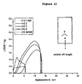
- the Force versus Displacement data for both the control and lased samples are depicted in Figure 12 .
- the maximum force held by the lased samples is significantly higher than that for the control sample. This proves that with respect to maximum force or load bearing capacity, cutting a multitude of holes in this thin film specimen increased transverse direction tensile properties by approximately two times.
Abstract
Description
- This application claims priority to provisional application USSN
61/381,286, filed September 9, 2010 - Thin films are routinely used to cover or repair valuable articles. In many applications, these thin films need to be secured in place via an attachment means. Unfortunately, the increased stresses that occur at the interface between the thin film itself and the attachment means often results in premature failure under load. There are many instances where a failure occurs at the interface between the attachment means and the thin film, such as when the surgical polymer film mesh affixed to body tissue during a hernia repair, or a when panels of a filter bag are sewn together, or when a synthetic graft is used in a medical procedure.
-
U.S. Patent 5,527,341 describes a method of using additional flat membrane layers to reinforce the hole region during tendon augmentation or repair.U.S. Patent 5,797.932 discusses a membrane hernia repair using a "platform-elevated part" approximately equivalent to the thickness of the base membrane. This double membrane thickness is intended to reduce tearing by the suture when after the membrane is stitched in place during the surgery. -
U.S. Patent 6,544,167 discusses securing a sheet material such as Dacron (Hemoshield), or polytetrafluroethylene (Gortex) to body tissue by providing a reinforcing "ring which will typically have a toroidal configuration with a circumferential cross section that is circular, and is typically formed of a plastic material or curled autogenous tissue such as fascia or pericardium, or any other biocompatible material." -
US 2002/0026092 A1 discusses a reinforcing "ring can be attached to the material by adhesive or by stitches passing over the ring and through the material. Alternatively, the ring can be sandwiched between two pieces of the sheet material. In this case, a second piece of the sheet material can be positioned on the side of the ring opposite to the sheet material. Appropriate sutures extending around the ring and through the materials and will sandwich the ring and maintain it in the preferred position. - European Patent Application
EP0352972A discusses the need for a thin wall expanded polytetrafluoroethylene (PTFE) "vascular graft which resists tearing by the sutures attaching it to perigraft material. [That inventive] composition comprises an expanded biocompatible fluoroplastic resin and biocompatible, high temperature-resistant fibers which are chemically compatible with the PTFE resin, wherein the fibers are distributed throughout the resin in a random orientation." - The present invention provides a method of increasing tear strength of polymer films as described herein.
- An aspect of the present invention relates to a method of increasing the tear strength of polymer films. This method also can be used to increase the force necessary to pull or otherwise remove an attachment means from a polymer film to which it is affixed. This method of increasing tear strength in a polymer film is demonstrated by the inclusion of at least one load distribution element in the polymer film at a location near the foci of the applied load or attachment means. Load distribution elements such as but not limited to slits, perforations, and other apertures are included herein. Said load distribution element, serving as a stress redistribution means, increases the load required for tear propagation through or within the film. In medical articles, such as but not limited to soft tissue patches, the present invention can be used to increase suture retention and similar load bearing characteristics. Thus, this method of increasing the load carrying capability of polymer films is provided herein.
- In the figures in which like reference designations indicate like elements.
-
Figure 1 is a schematic of a polymer film having a longitudinally oriented load distribution element, an attachment means, and a load source. -
Figure 2 is a schematic of a polymer film having a transversely oriented load distribution element, an attachment means, and a load source. -
Figure 3 is a schematic of a polymer film having a "hat" shaped load distribution element and a point load source. -
Figure 4 is a schematic of a polymer film having an aperture load distribution element and a point load source. -
Figure 5 is a top view of a circular polymer film having multiple load distribution elements and a load source -
Figure 6 is a top view of a circular polymer film having multiple load distribution elements of multiple sizes. -
Figure 7 is a schematic depicting how the radius of contact was determined in the Mesh Tension test method. -
Figure 8 is a graph of polymer film mesh orientation angle and suture pull-out force as a function of elliptical aperture aspect ratio. -
Figure 9 is a graph of tensile test displacement versus suture pull-out as a function of slit width. -
Figure 10 is a graph of tensile test displacement versus suture pull-out as a function of "hat" shaped slit width. -
Figure 11 is a graph of tear propagation results in the machine, longitudinal direction for a mesh having multiple load distribution means. -
Figure 12 is a graph of tear propagation results in the transverse direction for a mesh having multiple load distribution means. - The present invention provides a method of increasing tear strength in polymer films. In some embodiments, this method is suitable for polymer films to which a load is applied via an attachment point or an attachment means. The method involves the inclusion of at least one load distribution element in the polymer film at or near the foci of the applied load. This method is useful in a variety of applications including but not limited to surgical articles such as surgical polymer film meshes wherein there often is a need to increase suture retention. Thin, strong, polymer film-based, surgical polymer film meshes used to demonstrate the present invention may be useful for minimally invasive laparoscopic technique to correct vaginal prolapse, stress urinary incontinence, or similar pelvic floor disorder.
- Polymer films suitable for the present invention include, but not limited to, those produced by either casting or extrusion and in-plane (e.g. X-Y direction) expansion.
Figure 1 depicts a flat sheet of polymer film (10) to which a tether (30) is attached via attachment means (20). When a load (40) is applied to the tether (30), the force is transferred by the tether (30) to the polymer film (10) via attachment means (20). A skilled artisan will appreciate that a range of attachment means (20) may be employed with the present invention including but not limited to adhesives, mechanical interlocking, welding, bonding, sewing, or taping. One aspect of the present invention is the inclusion of at least one load distribution element (50) which effectively increases the load required for system failure. The load distribution means (50) in this embodiment is a longitudinally oriented slit having a length greater than the width of the attachment means (20). The point of system failure is defined as the load required to cause the polymer film (10) to be substantially separated from the applied load (40). One skilled in the art will appreciate that this separation may come about by detachment of the attachment means (20), failure the polymer film (10), failure of the tether (30) or any combination of thereof. - Polymer films to which the present invention applies are generally planar and have undergone in-plane expansion. These polymer films are substantially flat, thin, and flexible. They may be produced from any thermoplastic polymer or paste-extrudable polymer or castable polymer. Some typical thin films to which the present discovery applies include, but are not limited to, those made from polyolefin, polyurethane, silicone, Teflon®, or polytetrafluoroethylene (PTFE), and blends, copolymers, or composites thereof.
- Polymer films suitable for the present invention are typically thin, having a thickness less than about 0.10 inch. In some embodiments, the polymer film thickness is less than about 0.050 inch. In other embodiments, the polymer film thickness is less than about 0.010 inch. And in yet other embodiments, the polymer film thickness is less than 0.002 inch thick. These polymer films are flexible and can be rolled or crumpled or folded.
- A skilled artisan will appreciate that such thin polymer films are often produced from thicker films wherein the thickness is reduced by wet or dry calendaring, expansion, or both. Longitudinal, in-plane expansion (i.e. X-direction) is a common way to build strength while decreasing thickness. Subsequent inclusion of load distribution elements can further increase the longitudinal load bearing capacity of the film. The load bearing capacity of the film as described herein is defined as the tensile load required to cause specimen failure. Transverse expansion (i.e. Y-direction) may be used to build transverse strength. The inclusion of load distribution elements can further increase the transverse load bearing capacity of the film.
- Some polymer films of the present discovery may comprise expanded PTFE (ePTFE) which may be produced via processes known to one skilled in the art and based on
U.S. Patent 3953566 . The specific properties of the ePTFE films used herein may be tailored by the choice of PTFE resin and process conditions. In medical applications, the pore size of the resulting ePTFE film can be tailored to restrict tissue ingrowth. For many human medical applications, the ePTFE pore size should be less than the size of the cells to which it will be exposed. Typically, this requires the resulting ePTFE film to have an average pore size of 13 µm or less. -
Figure 2 depicts a bi-axially expanded polymer film (10) to which a tether (30) is attached via attachment means (20). When a longitudinally oriented load (40) is applied to the tether (30), the force is transferred from the tether (30) to the polymer film (10) via attachment means (20). The transversely oriented load distribution element (50) effectively increases the load bearing capacity of the system prior to failure. The load distribution element (50) inFigure 2 is a slit having a width greater than the width of the attachment means (20). The point of system failure is defined as the load required to cause the polymer film (10) to be substantially separated from the applied load (40). As before, one skilled in the area will appreciate that this separation may come about by detachment of the attachment means (20), failure the polymer film (10), failure of the tether (30) or any combination of thereof. -
Figure 3 depicts a bi-axially expanded polymer film (10) to which a tether (30) is attached directly at location (22). When a transversely oriented load (40) is applied to the tether (30), the force is transferred from the tether (30) to the polymer film (10) at location (22). The non-orthogonal load distribution element (50) effectively increases the longitudinal load bearing capacity of the system prior to failure. The load distribution element (50) inFigure 3 is a non-orthogonal slit having a longitudinal dimension greater than the width of the attachment at location (22) of the tether (30) to the polymer film (10). System failure is defined as the load required to cause the polymer film (10) to be substantially separated from the applied load (40). As before, one skilled in the art will appreciate that this separation may come about by failure the polymer film (10), failure of the tether (30), or a combination of thereof. -
Figure 4 depicts a bi-axially expanded polymer film (10) to which a tether (30) is attached directly at location (22). When a transversely oriented load (40) is applied to the tether (30), the force is transferred from the tether (30) to the polymer film (10) at location (22). An aperture load distribution element (50) effectively increases the longitudinal load bearing capacity of the system prior to failure. The load distribution element (50) inFigure 4 is an aperture having a longitudinal dimension greater than the width of the attachment at location (22) of the tether (30) to the polymer film (10). System failure is defined as the load required to cause the polymer film (10) to be substantially separated from the applied load (40). As before, one skilled in the art will appreciate that this separation may come about by failure the polymer film (10), failure of the tether (30), or a combination of thereof. -
Figure 5 depicts a perforated radially expanded polymer film (10) to which a tethers (30) are attached directly at location (22). When a transversely oriented load (40) is applied to the tether (30), the force is transferred from the tether (30) to the polymer film (10) at location (22). The tether may be a string or line or rope or suture or cable or any other similar tensile element. The attachment means at location (22) may be passing the tether (30) through the polymer film (10) or affixing it to the polymer film surface. The array of circumferentially oriented load distribution elements (50) effectively increase the load bearing capacity of the system prior to failure. Load distribution elements (50) inFigure 5 are slits. Other load distribution element types may also be used in this embodiment such as, but not limited to, cross-hatched slits, circles, ellipses, curved slits, and the like. System failure is defined as the load required to cause the polymer film (10) to be substantially separated from the applied load (40). As before, one skilled in the art will appreciate that this separation may come about by failure the polymer film (10), failure of the tether (30), or a combination of thereof. -
Figure 6 depicts a perforated radially expanded polymer film (10) in which different types of load distribution elements (50) are present. Some of the load distribution elements (50) inFigure 6 are an array of circumferentially oriented slits. In addition,Figure 6 depicts an additional set of load distribution elements (50) such as a uniform pattern of smaller perforations (55). Any combination of shapes and/or patterns of load distribution elements may be used in the present invention provided that the load distribution elements can deform under an applied tensile load and yield an increase in load to failure compared to the polymer film having no load distribution elements. - When the present invention is applied to a surgical patch or surgical polymer film mesh made from a microporous fluoropolymer or microporous biocompatible polymer, a second material may be imbibed into microstructure to impart additional functionality. In this instance, the article would comprise both macroscopic load distribution elements and microporous elements. Materials such as but not limited to a hydrogel may be imbibed into the microporous elements to enhance cell ingrowth. Optionally, a second material may be coated onto the external surface of the microporous material or applied to the internal surfaces of the microstructure of the microporous material. Coating materials such as, but not limited to, antibiotic or antiseptic materials may be useful to resist infection. The coating material, rheology, and process parameters can be adjusted to control the amount of material that is deposited on the available internal and/or external polymer film mesh surfaces. A broad range of complementary materials may be carried by or included in the present invention to meet the needs of numerous end applications.
- Repairing damaged or weakened body tissues requires a relatively strong polymer film mesh having multiple load distribution elements. For example with a ventral hernia repair, the present invention can provide a 15cm by 19cm elliptical polymer film mesh having a Mesh Tension greater than 32 N/cm and yet be thin enough to be rolled up for delivery through a 5mm trocar port. In the case of this 32 N/cm polymer film mesh, the thickness was about 0.01 cm. When an adhesion barrier is desired, a thinner polymer film mesh may be employed having a Mesh Tension greater than 16 N/cm. In which case, an even larger polymer film mesh will fit within the same 5mm delivery trocar port. Alternatively a similar size polymer film mesh (elliptical shape measuring 15cm x 19cm) could be packaged into a trocar having a diameter less than 5mm. A 4mm OD trocar may be used. Or a 3mm OD trocar may be used.
- The packaged polymer film mesh comprising at least one load distribution element may be sterilized while in a containment housing, or prior to insertion into the containment housing, or after relocation to the surgical device. Any suitable sterilization means may be used, including but not limited to γ-radiation, steam, ethylene oxide (EtO), and peroxide.
- In some surgical procedures, a different size or diameter delivery device may be warranted. The design parameters, including the number, size, shape, and location of load distribution element(s), may be changed accordingly. If the sole purpose is as an adhesion barrier, then a strength less than 16 N/cm may be useful in which case fewer load distribution elements may be necessary for a given polymer film thickness or a thinner film thickness could be used with equal or more load distribution elements. Alternatively, to meet small package size and high load requirements, the number, shape, and pattern of load distribution elements can be varied along with base polymer film properties.
- Mesh Tensions for the examples described below were measured in accordance with ASTM D3787 based on the measured force and the radius of contact (rcontact) with the ball.

- A nip impression kit (10002002 Nip Impression Kit from Metso Paper, P.O. Box 155, Ivy Industrial Park, Clarks Summit, PA 18411)) is used to measure the length of ball contact with the polymer film mesh. This kit contains a roll of carbon paper and a roll of plain white paper, which can be dispensed so that any given length of both will be obtained with the carbon side flush against the white paper. The two papers are inserted between the ball and the polymer film mesh. As the load or pressure is applied between the ball and the polymer film mesh the carbon paper will leave an ink mark impression in the shape of the knit on the white paper. The impression length on the white paper is measured with a steel ruler with 0.5 mm increments.
- The length of ball contact and the radius of the ball are used to determine the angle of contact as shown in
Figure 6 .


- where, 2 □ = angle of contact
- rball = radius of the ball
- rcontact = radius of contact
- Suture retention is a mechanical property reflecting the articles mechanical resistance under tension at a suture site placed in the article. To represent the load applied by a suture at a suture site, a small pin fixture was used in which a pin (typically 0.020", or multiple pins) was pressed through a 1 inch wide strip of the test article. The coupon/attached-pin-fixture combination is attached in a tensile test apparatus such as an Instron Tensile Tester. The crosshead speed was set to 200 mm/min. For purposes of this measure, the maximum force exhibited was as the 'suture retention' strength. However, other parameters shown in the stress-strain graphs in
Figures 6 and7 may also be used to define the reinforcement phenomenon described herein. - The following nonlimiting examples are provided to further illustrate the present invention.
- Fine powder of PTFE polymer as described and taught in
US Patent Number 6,541,589 , comprising perfluorobutylethylene modifier, was blended with Isopar K (Exxon Mobil Corp., Fairfax, VA) in the proportion of 0.200 g/g of fine powder. The lubricated powder was compressed in a cylinder to form a pellet and placed into an oven set at 70°C for approximately 8 hours. The compressed and heated pellet was ram extruded to produce an extrudate tape approximately 15.2 cm wide by 0.75 mm thick. The tape was then calendered between compression rolls, distended, and dried to yield a tape having matrix tensile strengths of 6 kpsi (machine direction) x 6 kpsi (transverse direction). The side of the resultant asymmetric polymer film mesh surface corresponding toTape 1 is herein considered the tight-structure side. - Fine powder of PTFE polymer (DuPont, Wilmington, DE) was blended with Isopar K (Exxon Mobil Corp., Fairfax, VA) in the proportion of 0.243 g/g of fine powder. The lubricated powder was compressed in a cylinder to form a pellet. The compressed pellet was ram extruded at room temperature to produce an extrudate tape approximately 15.2 cm wide by 0.75 mm thick. The tape was then calendered between compression rolls, set to a temperature of 38°C, to a thickness of 0.28 mm. The tape was then longitudinally distended 8% and dried. The process produced a calendered tape having matrix tensile strengths of 3.2 kpsi (machine direction) x 1.4kpsi (transverse direction). The side of the resultant asymmetric polymer film mesh surface corresponding to Tape 2 is herein considered the open-structure side.
- Six layers of
Tape 1 were stacked on top of one another, each layer being 90 degrees offset from the previous. The stack was compressed and laminated together under high vacuum (< 29"Hg) at 309°C and 100 k-lbs force for 4 minutes to full density on OEM press Model VAC-Q-LAM-1/75/14X13/2/4.0"/ E370C/N/N/N-C-480V (OEM Press Systems Inc., 311 S. Highland Ave., Fullerton, CA 92832). The compressed stack was allowed to cool and then cut into an 8.5 inch diameter circle. - The circular sample was gripped around the periphery and radially expanded at 300°C and an axial expansion rate of 3.0 inch/second to an area expansion of about 11.25:1. The radially expanded sample was then relaxed to achieve a 1.5:1 area reduction. The sample was removed and cut into a 9"x9" coupon. This process was repeated four times to create four radially expanded PTFE disks.
- A polymer film mesh was created by combining four radially expanded PTFE disks from above with one layer of Tape 2 into a single stacked coupon. The stacked coupon was compressed and laminated together under high vacuum (< 29"Hg) at 309°C and ∼100 k-lbs force for 4 minutes to approximately full density on OEM press Model VAC-Q-LAM-1/75/14X13/2/4.0"/E370C/N/N/N-C-480V (OEM Press Systems Inc., 311 S. Highland Ave., Fullerton, CA 92832). The compressed densified stack was allowed to cool and cut to an 8.5 inch circle. The circular sample was gripped around the periphery and expanded at 300°C and a rate of 0.2 inch/second axial displacement to an expansion ratio of about 11.25:1. The expanded polymer film mesh was then allowed to relax to an area reduction of about 1.5:1. The polymer film mesh was then restrained in a convection oven (ESPEC Model SSPH-201, 4141 Central Parkway, Hudsonville, MI 49426) at 350°C for 10 minutes, and then allowed to cool.
- A cross-sectional SEM of this microporous expanded asymmetric PTFE polymer film mesh article is shown in
Figure 5 . - A sample of the polymer film mesh from Example 1 was cut into 15 cm x 19 cm oval device using CO2 Plotter/Laser (Universal Laser Systems Model PLS6.60-50 16000 M 81st Street, Scottsdale, AZ 85260). Then GORE-TEX CV-2 sutures (W. L. Gore and Associates, Inc., 301 Airport Road, Elkton, MD 21921) were looped through at four cardinal locations: 12, 3, 6, and 9 o'clock positions. Each suture was passed about 0.5cm inward from the edge. Each suture was looped through the device such that the free ends were on the abdominal side of the device. The entry and exit point of each suture loop was about 0.5 cm apart. Next a thin, strong piece of a fluorinated ethylene propylene (FEP)/expanded PTFE (ePTFE) composite film was cut into an approximately 1cm x 0.5cm rectangle. The expanded PTFE film was prepared in conformance with
U.S. Patent 5476589A . The FEP layer was approximately 1 mil thick. This cut rectangle was placed on the open side of the sutured polymer film mesh so that each exposed suture was covered. These FEP/ePTFE rectangles where then welded to the polymer film mesh thereby securing the sutures in place. The welding was accomplished using a soldering gun with a blunt tip and set to 800°F and hand pressure (Weller WSD161, APEX Tool Group LLC., 14600 York Road Suite A, Sparks, MD 21152). - Suture Management designed to avoid suture entanglement was accomplished by bundling attached pairs of oriented sutures using coils produced from a "string" of bioabsorable polymer produced in conformance with
U.S. Patent Number 6,165,217 . The bioabsorbable film mass was 7 mg/cm2. This film was "cigarette rolled" to produce the "string". This "string" was then looped around sutures securing the parallel adjacent sutures. Heat (260°F, 10 seconds) was applied via heat gun (Steinel Model HL2010E, 9051 Lyndale Avenue, Bloomington, MN 55420) to retract and thermally set the bioabsorbable polymer. - The sutured polymer film mesh article from Example 2 was folded in half across the ellipse minor axis. The folded polymer film mesh was placed between two small mandrels (or a split mandrel) (New England Precision Grinding, 0.013"x70" PTFE coated 304SS mandrels, 35 Jeffrey Avenue, Holliston, MA 01746-2027) that were chucked on a horizontal rotary drill press and the drill press rotated to roll up sutured polymer film mesh device into a tight package around the mandrels. The rolled assembly was removed from the chucks, and the mandrels removed from within the rolled, sutured polymer film mesh. The rolled, sutured polymer film mesh was inserted into a ∼5.2mm ID tube (nylon tubing of 0.005" wall from Grilamid). The tube and rolled suture device was inserted into a 5mm trocar port of ID ∼5.5mm (
Covidien 15 Hampshire Street, Mansfield, MA 02048). Deployment of the sutured polymer film mesh was demonstrated when the rolled sutured polymer film mesh was easily pushed out of the trocar and unrolled onto the table top where is laid relatively flat. - The suture retention effect of creating elliptical apertures was determined using an ePTFE polymer film mesh article created in conformance with
U.S. Patent 7306729 . The base ePTFE material had matrix tensile strengths of 48kpsi and 46kpsi in the machine and transverse directions, respectively. The material was mounted in a CO2 plotter/laser (Universal Laser Systems Model PLS6.60-50 16000 M 81st Street, Scottsdale, AZ 85260). The beam was focused on the plane of the material. In the orientation of the test directions (machine direction, transverse direction, and 45 degree nominally), an ellipse having rmajor 0.05"and rminor 0.010" (i.e. 5:1 ratio) was laser cut from the material oriented so the ellipse was substantially parallel to the perimeter of the polymer film mesh article. The suture retention measurements were performed by sequentially locating the test pin in a lased aperture in each of the machine, transverse, and 45 degree directions. The results are shown inFigure 7 . - The suture retention effect of creating elliptical apertures was determined using an ePTFE polymer film mesh article created in conformance with
U.S. Patent 7306729 . The base ePTFE material had matrix tensile strengths of 48kpsi and 46kpsi in the machine and transverse directions, respectively. The material was mounted in a CO2 plotter/laser (Universal Laser Systems Model PLS6.60-50 16000 M 81st Street, Scottsdale, AZ 85260). The beam was focused on the plane of the material. In the orientation of the test directions (machine direction, transverse direction, and 45 degree nominally), an ellipse having rmajor 0.05"and rminor 0.025" (i.e. 5:1 ratio) was laser cut from the material oriented so the ellipse was substantially parallel to the perimeter of the polymer film mesh article. The suture retention measurements were performed by sequentially locating the test pin in a lased aperture in each of the machine, transverse, and 45 degree directions. The results are shown inFigure 7 . - The suture retention effect of creating elliptical apertures was determined using an ePTFE polymer film mesh article created in conformance with
U.S. Patent 7306729 . The base ePTFE material had matrix tensile strengths of 48kpsi and 46kpsi in the machine and transverse directions, respectively. The material was mounted in a CO2 plotter/laser (Universal Laser Systems Model PLS6.60-50 16000 M 81st Street, Scottsdale, AZ 85260). The beam was focused on the plane of the material. In the orientation of the test directions (machine direction, transverse direction, and 45 degree nominally), an ellipse having rmajor 0.05"and rminor 0.050" (i.e. 5:1 ratio) was laser cut from the material oriented so the ellipse was substantially parallel to the perimeter of the polymer film mesh article. The suture retention measurements were performed by sequentially locating the test pin in a lased aperture in each of the machine, transverse, and 45 degree directions. The results are shown inFigure 7 . - The suture retention effect of creating elliptical apertures was determined using an ePTFE polymer film mesh article created in conformance with
U.S. Patent 7306729 . The base ePTFE material had matrix tensile strengths of 48kpsi and 46kpsi in the machine and transverse directions, respectively. This control sample was tested by pressing the test pin through the polymer film mesh article in locations corresponding to each of the machine, transverse, and 45 degree directions. The results are shown inFigure 7 . - The effect on suture retention of creating a small slit near the suture location determined using an ePTFE polymer film mesh article created in conformance with
U.S. Patent 7306729 . The base ePTFE material had matrix tensile strengths of 48kpsi and 46kpsi in the machine and transverse directions, respectively. A small slit cut was cut with a razor blade approximately 0.5 cm in from and parallel to the edge of the polymer film mesh article. The test pin was then pressed through the polymer film mesh article at a location between the slit and the edge of the article. The tensile properties were measured.Figure 8 shows the suture pull-out tensile results as a function of slit length compared to a control sample having no slit. - The effect on suture retention of creating a small "hat" shaped slit near the suture location determined using an ePTFE polymer film mesh article created in conformance with
U.S. Patent 7306729 . The base ePTFE material had matrix tensile strengths of 48kpsi and 46kpsi in the machine and transverse directions, respectively. A small "hat" shaped slit cut was cut with a razor blade approximately 0.5 cm in from and parallel to the edge of the polymer film mesh article. The test pin was then pressed through the polymer film mesh article at a location between the "hat" shaped slit and the edge of the article. The tensile properties were measured.Figure 8 shows the suture pull-out tensile results as a function of the "hat" shaped slit length compared to a control sample having no slit. - Tear Resistance in the machine direction of a material comprising multiple load distribution elements was evaluated as follows: An ePTFE article was created based on
U.S. Patent 7306729 resulting in material of average mass of 193 g/m2, an average density of 2.1 g/cc, and an MTS (MD) 36 kpsi & (TD) 55 kpsi. The material was mounted in a CO2 plotter/laser (Universal Laser Systems Model PLS6.60-50 16000 M 81st Street, Scottsdale, AZ 85260). The beam was focused on the plane of the material. A matrix of ellipses of rmajor 0.02"and rminor 0.004" were lased into the continuous material. The ellipses were oriented with the minor-axis parallel to the machine direction of the material. The ellipses were longitudinally spaced apart 0.07" (nominal center-on-center), and 0.08" transversely (nominal edge-to-edge). The resulting material had a hole pattern as depicted by the uniform pattern of smaller perforations (55) inFigure 6 . - A 1 inch by 2 inch sample test coupon was cut and removed from both the as received material as well as material with the lased matrix of load distribution elements described in above in this Example. The tear propagation characteristics of each sample were tested substantially in accordance with ASTM D1938 Trouser Tear Method. The sample test coupon long axis was oriented parallel to the machine direction of the material. A sharp tear was initiated by manually slitting the coupon along the long axis using a sharp razor blade. Each tab was mounted in the lower and upper grips in a tensile tester, and tested at 200 mm/min crosshead speed and the resultant force trace was recorded. The Force versus Displacement data for both the control and lased samples are depicted in
Figure 11 . The maximum force held by the lased samples is significantly higher than that for the control sample. This proves that with respect to maximum force or load bearing capacity, cutting a multitude of holes in this thin film specimen increased machine direction tensile properties by approximately two times. - Tear Resistance in the transverse direction of a material comprising multiple load distribution elements was evaluated as follows: An ePTFE article was created based on
U.S. Patent 7306729 resulting in material of average mass of 193 g/m2, an average density of 2.1 g/cc, and an MTS (MD) 36 kpsi & (TD) 55 kpsi. The material was mounted in a CO2 plotter/laser (Universal Laser Systems Model PLS6.60-50 16000 M 81st Street, Scottsdale, AZ 85260). The beam was focused on the plane of the material. A matrix of ellipses of rmajor 0.02"and rminor 0.004" were lased into the continuous material. The ellipses were oriented with the minor-axis parallel to the transverse direction of the material. The ellipses were longitudinally spaced apart 0.07" (nominal center-on-center), and 0.08" transversely (nominal edge-to-edge). The resulting material had a hole pattern as depicted by the uniform pattern of smaller perforations (55) inFigure 6 . - A 1 inch by 2 inch sample test coupon was cut and removed from both the as received material as well as material with the lased matrix of load distribution elements described above in this Example. The tear propagation characteristics of each sample were tested substantially in accordance with ASTM D1938 Trouser Tear Method. The sample test coupon long axis was oriented parallel to the transverse direction of the material. A sharp tear was initiated by manually slitting the coupon along the long axis using a sharp razor blade. Each tab was mounted in the lower and upper grips in a tensile tester, and tested at 200 mm/min crosshead speed and the resultant force trace was recorded. The Force versus Displacement data for both the control and lased samples are depicted in
Figure 12 . The maximum force held by the lased samples is significantly higher than that for the control sample. This proves that with respect to maximum force or load bearing capacity, cutting a multitude of holes in this thin film specimen increased transverse direction tensile properties by approximately two times. - Further embodiments of the invention are disclosed in the following clauses:
- 1. A method for increasing the tensile strength of a polymer film comprising the steps of:
- a. providing a polymer film,
- b. creating a load distribution element in said polymer film,
- c. applying a tensile load to the polymer film on or near to the load distribution element, wherein the maximum tensile load is increased relative to a substantially equivalent system without the load distribution element.
- 2. The method of
Clause 1 wherein the load distribution element comprises a slit. - 3. The method of
Clause 1 wherein the load distribution element comprises an aperture - 4. The method of
Clause 1 wherein the polymer film has a thickness less than 0.10 inch. - 5. The method of
Clause 1 wherein the polymer film has a thickness less than 0.050 inch. - 6. The method of
Clause 1 wherein the polymer film has a thickness less than 0.010 inch. - 7. The method of
Clause 1 wherein the polymer film has a thickness less than 0.002 inch. - 8. The method of
Clause 1 wherein the tensile load is applied to the polymer film via a tether. - 9. The method of Clause 8 wherein the tether is attached to the polymer film via an attachment means.
- 10. The method of Clause 9 wherein the attachment means comprises an adhesive or a mechanical interlock or sewn connection.
- 11. A method for increasing the tensile strength of a surgical polymer film comprising the steps of:
- a. providing a surgical polymer film,
- b. creating a load distribution element in said surgical polymer film,
- c. attaching a tether to the surgical polymer film on or adjacent to the load distribution elements using a attachment means, wherein the attachment means comprises an adhesive, a mechanical interlock, or sewn connection,
- d. applying a tensile load to the polymer film via the tether, wherein the maximum tensile load is increased relative to a substantially equivalent system without the load distribution element.
- 12. The method of
Clause 11 wherein the attachment means comprises a suture. - 13. The method of
Clause 11 wherein the attachment means comprises a staple. - 14. The method of
Clause 11 wherein the attachment means comprises an adhesive.
Claims (15)
- A method for increasing the tensile strength of a polymer film comprising:creating an array of circumferentially oriented load distributions elements in a radially expanded polymer film;attaching tethers directly to said polymer film at a location; andapplying a transversely oriented load to said tethers, the force being transferred from the tethers to said polymer film on or near to the load distribution element, wherein the maximum tensile load is increased relative to a substantially equivalent system without the load distribution element.
- The method of claim 1, wherein the load distribution element comprises a slit.
- The method of claim 1, wherein the load distribution element comprises cross-hatched slits, circles, ellipses, or curved slits.
- The method of claim 1, wherein the load distribution element comprises an aperture.
- The method of claim 1, wherein the polymer film has a thickness less than 0.25 cm (0.10 inch).
- The method of claim 1, wherein the polymer film has a thickness less than 0.127 cm (0.050 inch).
- The method of claim 1, wherein the polymer film has a thickness less than 0.025 cm (0.010 inch).
- The method of claim 1, wherein the polymer film has a thickness less than 0.051 mm (0.002 inch).
- The method of claim 1, wherein the tether is attached to the polymer film via an attachment means.
- The method of claim 9, wherein the attachment means comprises an adhesive or a mechanical interlock, welding, bonding, sewing or taping.
- The method of claim 9, wherein the attachment means is passing the tether through the polymer film or affixing the tether to the polymer film surface.
- The method of any one of claims 9 to 11, wherein the load distribution element has a width greater than a width of the attachment means.
- The method of claim 1, wherein the failure comprises the tensile load required to cause the polymer film to be substantially separated from the applied tensile load.
- The method of claim 1, wherein the polymer film is a surgical polymer film mesh.
- The method of claim 1, wherein said tether is a string, a line, a rope, a suture or a cable.
Applications Claiming Priority (3)
| Application Number | Priority Date | Filing Date | Title |
|---|---|---|---|
| US38128610P | 2010-09-09 | 2010-09-09 | |
| PCT/US2011/050931 WO2012033977A1 (en) | 2010-09-09 | 2011-09-09 | Method of increasing film tear strength |
| EP11760919.8A EP2613711B1 (en) | 2010-09-09 | 2011-09-09 | Method of increasing film tear strength |
Related Parent Applications (2)
| Application Number | Title | Priority Date | Filing Date |
|---|---|---|---|
| EP11760919.8A Division EP2613711B1 (en) | 2010-09-09 | 2011-09-09 | Method of increasing film tear strength |
| EP11760919.8A Division-Into EP2613711B1 (en) | 2010-09-09 | 2011-09-09 | Method of increasing film tear strength |
Publications (2)
| Publication Number | Publication Date |
|---|---|
| EP3058878A1 true EP3058878A1 (en) | 2016-08-24 |
| EP3058878B1 EP3058878B1 (en) | 2019-07-17 |
Family
ID=44675832
Family Applications (2)
| Application Number | Title | Priority Date | Filing Date |
|---|---|---|---|
| EP11760919.8A Active EP2613711B1 (en) | 2010-09-09 | 2011-09-09 | Method of increasing film tear strength |
| EP16153194.2A Active EP3058878B1 (en) | 2010-09-09 | 2011-09-09 | Method of increasing film tear strength |
Family Applications Before (1)
| Application Number | Title | Priority Date | Filing Date |
|---|---|---|---|
| EP11760919.8A Active EP2613711B1 (en) | 2010-09-09 | 2011-09-09 | Method of increasing film tear strength |
Country Status (12)
| Country | Link |
|---|---|
| US (2) | US9403329B2 (en) |
| EP (2) | EP2613711B1 (en) |
| JP (2) | JP2013545627A (en) |
| KR (2) | KR20150089091A (en) |
| CN (1) | CN103200881B (en) |
| AU (1) | AU2011299100B2 (en) |
| BR (1) | BR112013005614A2 (en) |
| CA (2) | CA2810672C (en) |
| ES (2) | ES2746885T3 (en) |
| HK (1) | HK1181285A1 (en) |
| RU (1) | RU2534237C1 (en) |
| WO (1) | WO2012033977A1 (en) |
Cited By (1)
| Publication number | Priority date | Publication date | Assignee | Title |
|---|---|---|---|---|
| WO2019197353A1 (en) | 2018-04-13 | 2019-10-17 | Dsm Ip Assets B.V. | Modified porous polyolefin film and method for its production |
Families Citing this family (7)
| Publication number | Priority date | Publication date | Assignee | Title |
|---|---|---|---|---|
| BR112013005614A2 (en) | 2010-09-09 | 2020-08-25 | W. L. Gore & Associates, Inc. | method to increase the shear strength of a film |
| USD737050S1 (en) | 2013-11-04 | 2015-08-25 | Christopher Rice Ferguson | Expandable multipurpose tote bag |
| US10945831B2 (en) | 2016-06-03 | 2021-03-16 | Musculoskeletal Transplant Foundation | Asymmetric tissue graft |
| US10813743B2 (en) * | 2018-09-07 | 2020-10-27 | Musculoskeletal Transplant Foundation | Soft tissue repair grafts and processes for preparing and using same |
| USD895812S1 (en) | 2018-09-07 | 2020-09-08 | Musculoskeletal Transplant Foundation | Soft tissue repair graft |
| KR102269983B1 (en) | 2019-02-14 | 2021-06-28 | 재단법인대구경북과학기술원 | Biodegradable polyester resin composition with improved compatibility |
| WO2023094232A1 (en) * | 2021-11-24 | 2023-06-01 | Universiteit Gent | A source wafer and methods related thereto for micro-transfer printing |
Citations (12)
| Publication number | Priority date | Publication date | Assignee | Title |
|---|---|---|---|---|
| US3953566A (en) | 1970-05-21 | 1976-04-27 | W. L. Gore & Associates, Inc. | Process for producing porous products |
| EP0352972A2 (en) | 1988-07-29 | 1990-01-31 | BAXTER INTERNATIONAL INC. (a Delaware corporation) | Fiber-reinforced expanded fluoroplastic vascular grafts |
| US5321109A (en) * | 1992-11-17 | 1994-06-14 | Impra, Inc. | Uniformly expanded PTFE film |
| US5476589A (en) | 1995-03-10 | 1995-12-19 | W. L. Gore & Associates, Inc. | Porpous PTFE film and a manufacturing method therefor |
| US5527341A (en) | 1991-05-24 | 1996-06-18 | Synthes (U.S.A) | Resorbable tendon and bone augmentation device |
| US5797932A (en) | 1995-11-24 | 1998-08-25 | Jong-Deok Park | Muscle clamping device |
| US5866056A (en) * | 1995-12-05 | 1999-02-02 | Werner; Michael | Method of forming a gasket with centering collar |
| US6165217A (en) | 1997-10-02 | 2000-12-26 | Gore Enterprise Holdings, Inc. | Self-cohering, continuous filament non-woven webs |
| US20020026092A1 (en) | 1998-05-01 | 2002-02-28 | Buckberg Gerald D. | Ventricular restoration patch |
| WO2003002027A1 (en) * | 2001-06-27 | 2003-01-09 | Promedon Do Brasil Produtos Medico-Hospitalares Ltda | Adjustable autofixing sling for treatment of urinary incontinence |
| US6541589B1 (en) | 2001-10-15 | 2003-04-01 | Gore Enterprise Holdings, Inc. | Tetrafluoroethylene copolymer |
| US7306729B2 (en) | 2005-07-18 | 2007-12-11 | Gore Enterprise Holdings, Inc. | Porous PTFE materials and articles produced therefrom |
Family Cites Families (29)
| Publication number | Priority date | Publication date | Assignee | Title |
|---|---|---|---|---|
| FR943298A (en) | 1947-03-14 | 1949-03-03 | Tinxirol | Pore filler for the preparation of wood, in particular for varnishing, and its application as a plaster or mastic |
| US2671444A (en) | 1951-12-08 | 1954-03-09 | Jr Benjamin F Pease | Nonmetallic mesh surgical insert for hernia repair |
| US3054406A (en) | 1958-10-17 | 1962-09-18 | Phillips Petroleum Co | Surgical mesh |
| JPS5038755B1 (en) * | 1970-12-28 | 1975-12-11 | ||
| US3973063A (en) * | 1974-11-21 | 1976-08-03 | Mobil Oil Corporation | Spot blocked thermoplastic film laminate |
| US4452245A (en) | 1980-06-06 | 1984-06-05 | Usher Francis C | Surgical mesh and method |
| JPS62148538A (en) * | 1985-12-23 | 1987-07-02 | Oji Yuka Gouseishi Kk | Perforated resin drawn film |
| GB8809077D0 (en) * | 1988-04-18 | 1988-05-18 | Rasmussen O B | Polymeric bags & methods & apparatus for their production |
| US5358492A (en) | 1991-05-02 | 1994-10-25 | Feibus Miriam H | Woven surgical drain and method of making |
| US5263969A (en) | 1992-04-17 | 1993-11-23 | Phillips Edward H | Tool for the laparoscopic introduction of a mesh prosthesis |
| EP0726841B1 (en) * | 1993-02-18 | 2000-03-01 | W.L. Gore & Associates, Inc. | Macroscopically perforated porous polytetrafluoroethylene materials |
| WO1996009330A1 (en) * | 1994-09-21 | 1996-03-28 | Bmg Incorporated | Ultrahigh-molecular-weight polyethylene molding for artificial joint and process for producing the molding |
| US6099791A (en) * | 1996-03-08 | 2000-08-08 | Baxter International Inc. | Methods of manufacture of multiaxially oriented fluoropolymer films |
| US6042592A (en) | 1997-08-04 | 2000-03-28 | Meadox Medicals, Inc. | Thin soft tissue support mesh |
| FR2776179A1 (en) | 1998-03-20 | 1999-09-24 | Cousin Biotech | SURGICAL PLATE |
| US6042536A (en) * | 1998-08-13 | 2000-03-28 | Contimed, Inc. | Bladder sling |
| US6831205B2 (en) * | 1999-11-29 | 2004-12-14 | Clozex Medical, Llc | Bandage for wound or incision closure |
| US6329564B1 (en) * | 1999-11-29 | 2001-12-11 | Michael Lebner | Bandage for wound or incision closure |
| US6746458B1 (en) | 2000-09-07 | 2004-06-08 | William G. Cloud | Mesh material to repair hernias |
| EP1545285B1 (en) * | 2002-08-02 | 2010-11-10 | C.R. Bard, Inc. | Self anchoring sling and introducer system |
| EP1545390A4 (en) | 2002-08-23 | 2007-05-09 | Proxy Biomedical Ltd | Three dimensional implant |
| US20050004515A1 (en) * | 2002-11-15 | 2005-01-06 | Hart Charles C. | Steerable kink resistant sheath |
| GB0411360D0 (en) * | 2004-05-21 | 2004-06-23 | Mpathy Medical Devices Ltd | Implant |
| US8617188B2 (en) | 2005-02-03 | 2013-12-31 | Moshe Dudai | Surgical mesh, mesh introducing and placing devices and methods |
| US20060252980A1 (en) | 2005-05-04 | 2006-11-09 | Arnal Kevin R | Methods and Apparatus for Securing and Tensioning a Urethral Sling to Pubic Bone |
| EP1937183B1 (en) | 2005-09-12 | 2018-11-28 | Proxy Biomedical Limited | Soft tissue implants |
| US20070112361A1 (en) | 2005-11-07 | 2007-05-17 | Schonholz Steven M | Surgical repair systems and methods of using the same |
| JP5595419B2 (en) * | 2008-12-30 | 2014-09-24 | クック メディカル テクノロジーズ エルエルシー | Magnetic traction device |
| BR112013005614A2 (en) | 2010-09-09 | 2020-08-25 | W. L. Gore & Associates, Inc. | method to increase the shear strength of a film |
-
2011
- 2011-09-09 BR BR112013005614-2A patent/BR112013005614A2/en not_active Application Discontinuation
- 2011-09-09 AU AU2011299100A patent/AU2011299100B2/en active Active
- 2011-09-09 CA CA2810672A patent/CA2810672C/en active Active
- 2011-09-09 EP EP11760919.8A patent/EP2613711B1/en active Active
- 2011-09-09 WO PCT/US2011/050931 patent/WO2012033977A1/en active Application Filing
- 2011-09-09 ES ES16153194T patent/ES2746885T3/en active Active
- 2011-09-09 JP JP2013528313A patent/JP2013545627A/en not_active Withdrawn
- 2011-09-09 CA CA2971836A patent/CA2971836C/en active Active
- 2011-09-09 EP EP16153194.2A patent/EP3058878B1/en active Active
- 2011-09-09 CN CN201180053913.4A patent/CN103200881B/en active Active
- 2011-09-09 ES ES11760919.8T patent/ES2575584T3/en active Active
- 2011-09-09 RU RU2013115772/05A patent/RU2534237C1/en active
- 2011-09-09 KR KR1020157018868A patent/KR20150089091A/en active Search and Examination
- 2011-09-09 KR KR1020137008728A patent/KR20130069793A/en active Application Filing
- 2011-09-09 US US13/228,600 patent/US9403329B2/en active Active
-
2013
- 2013-07-23 HK HK13108621.5A patent/HK1181285A1/en unknown
-
2016
- 2016-06-02 JP JP2016110982A patent/JP6243477B2/en active Active
- 2016-08-01 US US15/225,598 patent/US10918471B2/en active Active
Patent Citations (13)
| Publication number | Priority date | Publication date | Assignee | Title |
|---|---|---|---|---|
| US3953566A (en) | 1970-05-21 | 1976-04-27 | W. L. Gore & Associates, Inc. | Process for producing porous products |
| EP0352972A2 (en) | 1988-07-29 | 1990-01-31 | BAXTER INTERNATIONAL INC. (a Delaware corporation) | Fiber-reinforced expanded fluoroplastic vascular grafts |
| US5527341A (en) | 1991-05-24 | 1996-06-18 | Synthes (U.S.A) | Resorbable tendon and bone augmentation device |
| US5321109A (en) * | 1992-11-17 | 1994-06-14 | Impra, Inc. | Uniformly expanded PTFE film |
| US5476589A (en) | 1995-03-10 | 1995-12-19 | W. L. Gore & Associates, Inc. | Porpous PTFE film and a manufacturing method therefor |
| US5797932A (en) | 1995-11-24 | 1998-08-25 | Jong-Deok Park | Muscle clamping device |
| US5866056A (en) * | 1995-12-05 | 1999-02-02 | Werner; Michael | Method of forming a gasket with centering collar |
| US6165217A (en) | 1997-10-02 | 2000-12-26 | Gore Enterprise Holdings, Inc. | Self-cohering, continuous filament non-woven webs |
| US20020026092A1 (en) | 1998-05-01 | 2002-02-28 | Buckberg Gerald D. | Ventricular restoration patch |
| US6544167B2 (en) | 1998-05-01 | 2003-04-08 | Correstore, Inc. | Ventricular restoration patch |
| WO2003002027A1 (en) * | 2001-06-27 | 2003-01-09 | Promedon Do Brasil Produtos Medico-Hospitalares Ltda | Adjustable autofixing sling for treatment of urinary incontinence |
| US6541589B1 (en) | 2001-10-15 | 2003-04-01 | Gore Enterprise Holdings, Inc. | Tetrafluoroethylene copolymer |
| US7306729B2 (en) | 2005-07-18 | 2007-12-11 | Gore Enterprise Holdings, Inc. | Porous PTFE materials and articles produced therefrom |
Cited By (1)
| Publication number | Priority date | Publication date | Assignee | Title |
|---|---|---|---|---|
| WO2019197353A1 (en) | 2018-04-13 | 2019-10-17 | Dsm Ip Assets B.V. | Modified porous polyolefin film and method for its production |
Also Published As
| Publication number | Publication date |
|---|---|
| BR112013005614A2 (en) | 2020-08-25 |
| AU2011299100A1 (en) | 2013-03-21 |
| US20120061004A1 (en) | 2012-03-15 |
| CA2810672C (en) | 2017-07-18 |
| JP2013545627A (en) | 2013-12-26 |
| CA2810672A1 (en) | 2012-03-15 |
| ES2575584T3 (en) | 2016-06-29 |
| HK1181285A1 (en) | 2013-11-08 |
| CN103200881A (en) | 2013-07-10 |
| CA2971836A1 (en) | 2012-03-15 |
| CA2971836C (en) | 2019-10-01 |
| RU2013115772A (en) | 2014-11-10 |
| WO2012033977A1 (en) | 2012-03-15 |
| EP3058878B1 (en) | 2019-07-17 |
| US10918471B2 (en) | 2021-02-16 |
| KR20130069793A (en) | 2013-06-26 |
| CN103200881B (en) | 2015-03-11 |
| RU2534237C1 (en) | 2014-11-27 |
| AU2011299100B2 (en) | 2015-01-22 |
| JP2016180111A (en) | 2016-10-13 |
| EP2613711B1 (en) | 2016-03-23 |
| ES2746885T3 (en) | 2020-03-09 |
| EP2613711A1 (en) | 2013-07-17 |
| US9403329B2 (en) | 2016-08-02 |
| KR20150089091A (en) | 2015-08-04 |
| US20160338818A1 (en) | 2016-11-24 |
| JP6243477B2 (en) | 2017-12-06 |
Similar Documents
| Publication | Publication Date | Title |
|---|---|---|
| US10918471B2 (en) | Increased film tear strength | |
| US20120065649A1 (en) | Surgical Mesh | |
| CA2192457C (en) | High strength porous ptfe sheet material | |
| CA2155326C (en) | A laminated patch tissue repair sheet material | |
| US9750594B2 (en) | Soft tissue implants and methods for making same | |
| CA2481166C (en) | Improved membrane for use in sutured or sutureless surgical procedures | |
| EP2378983A1 (en) | Implantable prosthesis | |
| WO2004006808A2 (en) | Soft tissue implants and methods for making same |
Legal Events
| Date | Code | Title | Description |
|---|---|---|---|
| PUAI | Public reference made under article 153(3) epc to a published international application that has entered the european phase |
Free format text: ORIGINAL CODE: 0009012 |
|
| 17P | Request for examination filed |
Effective date: 20160128 |
|
| AC | Divisional application: reference to earlier application |
Ref document number: 2613711 Country of ref document: EP Kind code of ref document: P |
|
| AK | Designated contracting states |
Kind code of ref document: A1 Designated state(s): AL AT BE BG CH CY CZ DE DK EE ES FI FR GB GR HR HU IE IS IT LI LT LU LV MC MK MT NL NO PL PT RO RS SE SI SK SM TR |
|
| REG | Reference to a national code |
Ref country code: HK Ref legal event code: DE Ref document number: 1226930 Country of ref document: HK |
|
| STAA | Information on the status of an ep patent application or granted ep patent |
Free format text: STATUS: EXAMINATION IS IN PROGRESS |
|
| 17Q | First examination report despatched |
Effective date: 20180621 |
|
| REG | Reference to a national code |
Ref country code: DE Ref legal event code: R079 Ref document number: 602011060591 Country of ref document: DE Free format text: PREVIOUS MAIN CLASS: A61B0017040000 Ipc: A61B0046200000 |
|
| GRAP | Despatch of communication of intention to grant a patent |
Free format text: ORIGINAL CODE: EPIDOSNIGR1 |
|
| STAA | Information on the status of an ep patent application or granted ep patent |
Free format text: STATUS: GRANT OF PATENT IS INTENDED |
|
| RIC1 | Information provided on ipc code assigned before grant |
Ipc: B29C 55/04 20060101ALI20190115BHEP Ipc: B29C 65/62 20060101ALI20190115BHEP Ipc: A61F 2/00 20060101ALI20190115BHEP Ipc: B29D 7/01 20060101ALI20190115BHEP Ipc: B32B 38/04 20060101ALI20190115BHEP Ipc: B29C 55/12 20060101ALI20190115BHEP Ipc: A61B 17/064 20060101ALI20190115BHEP Ipc: B29L 31/00 20060101ALN20190115BHEP Ipc: B29C 65/82 20060101ALI20190115BHEP Ipc: B29C 65/00 20060101ALI20190115BHEP Ipc: B29C 65/56 20060101ALI20190115BHEP Ipc: A61B 46/20 20160101AFI20190115BHEP Ipc: A61B 17/04 20060101ALI20190115BHEP Ipc: B29K 627/18 20060101ALN20190115BHEP Ipc: B29C 65/48 20060101ALI20190115BHEP |
|
| INTG | Intention to grant announced |
Effective date: 20190218 |
|
| GRAS | Grant fee paid |
Free format text: ORIGINAL CODE: EPIDOSNIGR3 |
|
| GRAA | (expected) grant |
Free format text: ORIGINAL CODE: 0009210 |
|
| STAA | Information on the status of an ep patent application or granted ep patent |
Free format text: STATUS: THE PATENT HAS BEEN GRANTED |
|
| AC | Divisional application: reference to earlier application |
Ref document number: 2613711 Country of ref document: EP Kind code of ref document: P |
|
| AK | Designated contracting states |
Kind code of ref document: B1 Designated state(s): AL AT BE BG CH CY CZ DE DK EE ES FI FR GB GR HR HU IE IS IT LI LT LU LV MC MK MT NL NO PL PT RO RS SE SI SK SM TR |
|
| REG | Reference to a national code |
Ref country code: GB Ref legal event code: FG4D |
|
| REG | Reference to a national code |
Ref country code: CH Ref legal event code: EP |
|
| REG | Reference to a national code |
Ref country code: IE Ref legal event code: FG4D |
|
| REG | Reference to a national code |
Ref country code: DE Ref legal event code: R096 Ref document number: 602011060591 Country of ref document: DE |
|
| REG | Reference to a national code |
Ref country code: AT Ref legal event code: REF Ref document number: 1155123 Country of ref document: AT Kind code of ref document: T Effective date: 20190815 |
|
| REG | Reference to a national code |
Ref country code: NL Ref legal event code: MP Effective date: 20190717 |
|
| REG | Reference to a national code |
Ref country code: LT Ref legal event code: MG4D |
|
| REG | Reference to a national code |
Ref country code: AT Ref legal event code: MK05 Ref document number: 1155123 Country of ref document: AT Kind code of ref document: T Effective date: 20190717 |
|
| PG25 | Lapsed in a contracting state [announced via postgrant information from national office to epo] |
Ref country code: HR Free format text: LAPSE BECAUSE OF FAILURE TO SUBMIT A TRANSLATION OF THE DESCRIPTION OR TO PAY THE FEE WITHIN THE PRESCRIBED TIME-LIMIT Effective date: 20190717 Ref country code: AT Free format text: LAPSE BECAUSE OF FAILURE TO SUBMIT A TRANSLATION OF THE DESCRIPTION OR TO PAY THE FEE WITHIN THE PRESCRIBED TIME-LIMIT Effective date: 20190717 Ref country code: SE Free format text: LAPSE BECAUSE OF FAILURE TO SUBMIT A TRANSLATION OF THE DESCRIPTION OR TO PAY THE FEE WITHIN THE PRESCRIBED TIME-LIMIT Effective date: 20190717 Ref country code: NO Free format text: LAPSE BECAUSE OF FAILURE TO SUBMIT A TRANSLATION OF THE DESCRIPTION OR TO PAY THE FEE WITHIN THE PRESCRIBED TIME-LIMIT Effective date: 20191017 Ref country code: FI Free format text: LAPSE BECAUSE OF FAILURE TO SUBMIT A TRANSLATION OF THE DESCRIPTION OR TO PAY THE FEE WITHIN THE PRESCRIBED TIME-LIMIT Effective date: 20190717 Ref country code: BG Free format text: LAPSE BECAUSE OF FAILURE TO SUBMIT A TRANSLATION OF THE DESCRIPTION OR TO PAY THE FEE WITHIN THE PRESCRIBED TIME-LIMIT Effective date: 20191017 Ref country code: NL Free format text: LAPSE BECAUSE OF FAILURE TO SUBMIT A TRANSLATION OF THE DESCRIPTION OR TO PAY THE FEE WITHIN THE PRESCRIBED TIME-LIMIT Effective date: 20190717 Ref country code: PT Free format text: LAPSE BECAUSE OF FAILURE TO SUBMIT A TRANSLATION OF THE DESCRIPTION OR TO PAY THE FEE WITHIN THE PRESCRIBED TIME-LIMIT Effective date: 20191118 Ref country code: LT Free format text: LAPSE BECAUSE OF FAILURE TO SUBMIT A TRANSLATION OF THE DESCRIPTION OR TO PAY THE FEE WITHIN THE PRESCRIBED TIME-LIMIT Effective date: 20190717 |
|
| PG25 | Lapsed in a contracting state [announced via postgrant information from national office to epo] |
Ref country code: IS Free format text: LAPSE BECAUSE OF FAILURE TO SUBMIT A TRANSLATION OF THE DESCRIPTION OR TO PAY THE FEE WITHIN THE PRESCRIBED TIME-LIMIT Effective date: 20191117 Ref country code: RS Free format text: LAPSE BECAUSE OF FAILURE TO SUBMIT A TRANSLATION OF THE DESCRIPTION OR TO PAY THE FEE WITHIN THE PRESCRIBED TIME-LIMIT Effective date: 20190717 Ref country code: AL Free format text: LAPSE BECAUSE OF FAILURE TO SUBMIT A TRANSLATION OF THE DESCRIPTION OR TO PAY THE FEE WITHIN THE PRESCRIBED TIME-LIMIT Effective date: 20190717 Ref country code: LV Free format text: LAPSE BECAUSE OF FAILURE TO SUBMIT A TRANSLATION OF THE DESCRIPTION OR TO PAY THE FEE WITHIN THE PRESCRIBED TIME-LIMIT Effective date: 20190717 Ref country code: GR Free format text: LAPSE BECAUSE OF FAILURE TO SUBMIT A TRANSLATION OF THE DESCRIPTION OR TO PAY THE FEE WITHIN THE PRESCRIBED TIME-LIMIT Effective date: 20191018 |
|
| REG | Reference to a national code |
Ref country code: ES Ref legal event code: FG2A Ref document number: 2746885 Country of ref document: ES Kind code of ref document: T3 Effective date: 20200309 |
|
| PG25 | Lapsed in a contracting state [announced via postgrant information from national office to epo] |
Ref country code: TR Free format text: LAPSE BECAUSE OF FAILURE TO SUBMIT A TRANSLATION OF THE DESCRIPTION OR TO PAY THE FEE WITHIN THE PRESCRIBED TIME-LIMIT Effective date: 20190717 |
|
| PG25 | Lapsed in a contracting state [announced via postgrant information from national office to epo] |
Ref country code: DK Free format text: LAPSE BECAUSE OF FAILURE TO SUBMIT A TRANSLATION OF THE DESCRIPTION OR TO PAY THE FEE WITHIN THE PRESCRIBED TIME-LIMIT Effective date: 20190717 Ref country code: PL Free format text: LAPSE BECAUSE OF FAILURE TO SUBMIT A TRANSLATION OF THE DESCRIPTION OR TO PAY THE FEE WITHIN THE PRESCRIBED TIME-LIMIT Effective date: 20190717 Ref country code: RO Free format text: LAPSE BECAUSE OF FAILURE TO SUBMIT A TRANSLATION OF THE DESCRIPTION OR TO PAY THE FEE WITHIN THE PRESCRIBED TIME-LIMIT Effective date: 20190717 Ref country code: EE Free format text: LAPSE BECAUSE OF FAILURE TO SUBMIT A TRANSLATION OF THE DESCRIPTION OR TO PAY THE FEE WITHIN THE PRESCRIBED TIME-LIMIT Effective date: 20190717 |
|
| PG25 | Lapsed in a contracting state [announced via postgrant information from national office to epo] |
Ref country code: SM Free format text: LAPSE BECAUSE OF FAILURE TO SUBMIT A TRANSLATION OF THE DESCRIPTION OR TO PAY THE FEE WITHIN THE PRESCRIBED TIME-LIMIT Effective date: 20190717 Ref country code: IS Free format text: LAPSE BECAUSE OF FAILURE TO SUBMIT A TRANSLATION OF THE DESCRIPTION OR TO PAY THE FEE WITHIN THE PRESCRIBED TIME-LIMIT Effective date: 20200224 Ref country code: CZ Free format text: LAPSE BECAUSE OF FAILURE TO SUBMIT A TRANSLATION OF THE DESCRIPTION OR TO PAY THE FEE WITHIN THE PRESCRIBED TIME-LIMIT Effective date: 20190717 Ref country code: SK Free format text: LAPSE BECAUSE OF FAILURE TO SUBMIT A TRANSLATION OF THE DESCRIPTION OR TO PAY THE FEE WITHIN THE PRESCRIBED TIME-LIMIT Effective date: 20190717 Ref country code: MC Free format text: LAPSE BECAUSE OF FAILURE TO SUBMIT A TRANSLATION OF THE DESCRIPTION OR TO PAY THE FEE WITHIN THE PRESCRIBED TIME-LIMIT Effective date: 20190717 |
|
| REG | Reference to a national code |
Ref country code: CH Ref legal event code: PL |
|
| REG | Reference to a national code |
Ref country code: DE Ref legal event code: R097 Ref document number: 602011060591 Country of ref document: DE |
|
| PLBE | No opposition filed within time limit |
Free format text: ORIGINAL CODE: 0009261 |
|
| STAA | Information on the status of an ep patent application or granted ep patent |
Free format text: STATUS: NO OPPOSITION FILED WITHIN TIME LIMIT |
|
| PG2D | Information on lapse in contracting state deleted |
Ref country code: IS |
|
| PG25 | Lapsed in a contracting state [announced via postgrant information from national office to epo] |
Ref country code: CH Free format text: LAPSE BECAUSE OF NON-PAYMENT OF DUE FEES Effective date: 20190930 Ref country code: LU Free format text: LAPSE BECAUSE OF NON-PAYMENT OF DUE FEES Effective date: 20190909 Ref country code: LI Free format text: LAPSE BECAUSE OF NON-PAYMENT OF DUE FEES Effective date: 20190930 |
|
| 26N | No opposition filed |
Effective date: 20200603 |
|
| REG | Reference to a national code |
Ref country code: BE Ref legal event code: MM Effective date: 20190930 |
|
| PG25 | Lapsed in a contracting state [announced via postgrant information from national office to epo] |
Ref country code: BE Free format text: LAPSE BECAUSE OF NON-PAYMENT OF DUE FEES Effective date: 20190930 Ref country code: SI Free format text: LAPSE BECAUSE OF FAILURE TO SUBMIT A TRANSLATION OF THE DESCRIPTION OR TO PAY THE FEE WITHIN THE PRESCRIBED TIME-LIMIT Effective date: 20190717 |
|
| PG25 | Lapsed in a contracting state [announced via postgrant information from national office to epo] |
Ref country code: CY Free format text: LAPSE BECAUSE OF FAILURE TO SUBMIT A TRANSLATION OF THE DESCRIPTION OR TO PAY THE FEE WITHIN THE PRESCRIBED TIME-LIMIT Effective date: 20190717 |
|
| PG25 | Lapsed in a contracting state [announced via postgrant information from national office to epo] |
Ref country code: HU Free format text: LAPSE BECAUSE OF FAILURE TO SUBMIT A TRANSLATION OF THE DESCRIPTION OR TO PAY THE FEE WITHIN THE PRESCRIBED TIME-LIMIT; INVALID AB INITIO Effective date: 20110909 Ref country code: MT Free format text: LAPSE BECAUSE OF FAILURE TO SUBMIT A TRANSLATION OF THE DESCRIPTION OR TO PAY THE FEE WITHIN THE PRESCRIBED TIME-LIMIT Effective date: 20190717 |
|
| PG25 | Lapsed in a contracting state [announced via postgrant information from national office to epo] |
Ref country code: MK Free format text: LAPSE BECAUSE OF FAILURE TO SUBMIT A TRANSLATION OF THE DESCRIPTION OR TO PAY THE FEE WITHIN THE PRESCRIBED TIME-LIMIT Effective date: 20190717 |
|
| PGFP | Annual fee paid to national office [announced via postgrant information from national office to epo] |
Ref country code: IT Payment date: 20230822 Year of fee payment: 13 Ref country code: IE Payment date: 20230823 Year of fee payment: 13 Ref country code: GB Payment date: 20230823 Year of fee payment: 13 |
|
| PGFP | Annual fee paid to national office [announced via postgrant information from national office to epo] |
Ref country code: FR Payment date: 20230822 Year of fee payment: 13 Ref country code: DE Payment date: 20230822 Year of fee payment: 13 |
|
| PGFP | Annual fee paid to national office [announced via postgrant information from national office to epo] |
Ref country code: ES Payment date: 20231002 Year of fee payment: 13 |