EP3029244A1 - Cover member for a function-critical component with a plastic support element - Google Patents
Cover member for a function-critical component with a plastic support element Download PDFInfo
- Publication number
- EP3029244A1 EP3029244A1 EP14196288.6A EP14196288A EP3029244A1 EP 3029244 A1 EP3029244 A1 EP 3029244A1 EP 14196288 A EP14196288 A EP 14196288A EP 3029244 A1 EP3029244 A1 EP 3029244A1
- Authority
- EP
- European Patent Office
- Prior art keywords
- carrier element
- fastening means
- shutter body
- diaphragm
- essential component
- Prior art date
- Legal status (The legal status is an assumption and is not a legal conclusion. Google has not performed a legal analysis and makes no representation as to the accuracy of the status listed.)
- Granted
Links
- 239000004033 plastic Substances 0.000 title claims abstract description 17
- 239000000463 material Substances 0.000 claims abstract description 10
- 239000011521 glass Substances 0.000 claims description 10
- 239000002184 metal Substances 0.000 claims description 8
- 239000010985 leather Substances 0.000 claims description 2
- 239000002023 wood Substances 0.000 claims description 2
- 230000001681 protective effect Effects 0.000 description 11
- 230000008901 benefit Effects 0.000 description 9
- 230000006870 function Effects 0.000 description 8
- 238000004519 manufacturing process Methods 0.000 description 6
- 238000000034 method Methods 0.000 description 5
- 239000000853 adhesive Substances 0.000 description 4
- 230000001070 adhesive effect Effects 0.000 description 4
- 239000000155 melt Substances 0.000 description 4
- 230000008569 process Effects 0.000 description 4
- 239000012876 carrier material Substances 0.000 description 3
- 230000000694 effects Effects 0.000 description 3
- 238000001746 injection moulding Methods 0.000 description 3
- 238000003466 welding Methods 0.000 description 3
- 208000027418 Wounds and injury Diseases 0.000 description 2
- 230000009471 action Effects 0.000 description 2
- 230000006378 damage Effects 0.000 description 2
- 208000014674 injury Diseases 0.000 description 2
- 230000009993 protective function Effects 0.000 description 2
- 238000010146 3D printing Methods 0.000 description 1
- 229920000049 Carbon (fiber) Polymers 0.000 description 1
- 240000006829 Ficus sundaica Species 0.000 description 1
- 230000002730 additional effect Effects 0.000 description 1
- 238000005452 bending Methods 0.000 description 1
- 230000015572 biosynthetic process Effects 0.000 description 1
- 239000004917 carbon fiber Substances 0.000 description 1
- 239000011248 coating agent Substances 0.000 description 1
- 238000000576 coating method Methods 0.000 description 1
- 239000003086 colorant Substances 0.000 description 1
- 230000001419 dependent effect Effects 0.000 description 1
- 238000010586 diagram Methods 0.000 description 1
- 238000007667 floating Methods 0.000 description 1
- 239000000203 mixture Substances 0.000 description 1
- 239000003973 paint Substances 0.000 description 1
- 239000012779 reinforcing material Substances 0.000 description 1
- 230000003716 rejuvenation Effects 0.000 description 1
- 238000007493 shaping process Methods 0.000 description 1
- 239000002344 surface layer Substances 0.000 description 1
- 230000000007 visual effect Effects 0.000 description 1
- 239000013585 weight reducing agent Substances 0.000 description 1
Images


Classifications
-
- E—FIXED CONSTRUCTIONS
- E05—LOCKS; KEYS; WINDOW OR DOOR FITTINGS; SAFES
- E05D—HINGES OR SUSPENSION DEVICES FOR DOORS, WINDOWS OR WINGS
- E05D11/00—Additional features or accessories of hinges
- E05D11/0054—Covers, e.g. for protection
-
- E—FIXED CONSTRUCTIONS
- E06—DOORS, WINDOWS, SHUTTERS, OR ROLLER BLINDS IN GENERAL; LADDERS
- E06B—FIXED OR MOVABLE CLOSURES FOR OPENINGS IN BUILDINGS, VEHICLES, FENCES OR LIKE ENCLOSURES IN GENERAL, e.g. DOORS, WINDOWS, BLINDS, GATES
- E06B3/00—Window sashes, door leaves, or like elements for closing wall or like openings; Layout of fixed or moving closures, e.g. windows in wall or like openings; Features of rigidly-mounted outer frames relating to the mounting of wing frames
- E06B3/30—Coverings, e.g. protecting against weather, for decorative purposes
- E06B3/308—Wing frames covered on the outside by a rigidly-mounted outer frame
-
- E—FIXED CONSTRUCTIONS
- E05—LOCKS; KEYS; WINDOW OR DOOR FITTINGS; SAFES
- E05Y—INDEXING SCHEME RELATING TO HINGES OR OTHER SUSPENSION DEVICES FOR DOORS, WINDOWS OR WINGS AND DEVICES FOR MOVING WINGS INTO OPEN OR CLOSED POSITION, CHECKS FOR WINGS AND WING FITTINGS NOT OTHERWISE PROVIDED FOR, CONCERNED WITH THE FUNCTIONING OF THE WING
- E05Y2201/00—Constructional elements; Accessories therefore
- E05Y2201/10—Covers; Housings
- E05Y2201/11—Covers
Definitions
- the invention relates to a visor body for a functionally essential component, in particular for a fitting.
- Apertures are known from the prior art, which are arranged in particular on door fittings and / or corner fittings of doors or walls, in particular of glass. These diaphragms are formed of metal, sheet metal and often shaped in three dimensions, wherein the shaping is to be adjusted individually with respect to the component.
- the production method of such panels is difficult, expensive and inflexible with respect to the overall production process.
- Object of the present invention is at least partially overcome the disadvantages described above.
- a visor body for a functionally essential component, in particular for a fitting, with an aperture acting at least as a decorative element and a carrier element which has at least one fastening means in order to achieve an attachment to the functionally essential component, wherein the carrier element is formed from a plastic material is.
- a support element is proposed, which is easily adaptable to different geometries of the functionally essential component, wherein the support element is made of a plastic, whereby the total weight can be substantially reduced.
- the carrier element may be a plastic injection-molded part or a 3D-printing part.
- the carrier element may have one or more attachment means which are suitable for achieving a reliable fixation of the visor body on the functionally essential component.
- the bezel is particularly suitable for fitting for glass doors or glass walls.
- the formation of the carrier material made of plastic includes only a partial training of plastic. So z. B. on the plastic, a surface layer, for. As a paint or a laminate may be arranged. Additionally or alternatively, the carrier material reinforcing material, for. B. carbon fibers have. In a particularly preferred embodiment, the carrier material is completely formed from plastic.
- a diaphragm which is designed the same for different components essential to the function, is used come, depending on the geometry of the functionally essential component, a corresponding made of plastic carrier element is used, which is connected to the diaphragm.
- the visor body is composed of at least the decorative panel and the carrier element.
- the panel as well as the carrier element can be designed, for example, from a common body, which means that the panel and carrier element form a monolithic, common component. Consequently, this component, which is made of plastic, contribute significantly to the weight reduction.
- Corresponding fastening means ensure that the visor body can be fastened quickly to the functionally essential component without substantial assembly effort.
- fastening means in particular on the panel and / or on the carrier element are arranged, which justify their attachment function in dependence on different functionally essential components.
- a visor body can be standardized in order to be arranged on different geometries of functionally essential components.
- the fastening means may be arranged at different positions on the visor body, wherein their function as a fastening means depending on the geometry of the functionally essential component is needed or not.
- the diaphragm and the carrier element are made of different components, wherein the carrier element is fastened to the diaphragm via connecting elements.
- a diaphragm which is designed the same for different components essential to the function, are used come, which is fixed to the support element, wherein, for example, the support member has at least one fastening means to fix the visor body on the functionally essential component.
- the fastening means with the carrier element forms a common, monolithic component and / or the fastening means is integrally connected to the carrier element.
- the number of components can be reduced to a visor body, wherein it has been shown advantageously that thereby a simple assembly of the visor body can be achieved to the functionally essential component.
- the manufacturing costs can be reduced if the fastening means is integrated on the carrier element.
- the fastening means has a latching element and / or a clip element.
- such fastening means can be produced easily, in particular as a plastic injection-molded component.
- Another advantage is that such fastening means favor a simple assembly.
- the diaphragm is formed from a material which is made of metal and / or glass and / or wood and / or leather and / or plastic.
- a visor body can be provided according to the invention, which can satisfy a variety of design needs.
- a metallic diaphragm is characterized by its high stability, wherein the metal also represents an increased protective function for the functionally essential component. If the visor body is used on glass walls / glass doors, an aperture made of glass can make sense, so that a uniform overall picture can be achieved.
- the made of plastic panel can be different Have design designs, in particular be formed of one or several colors.
- an aperture made of plastic can be inventively provided that the surface of the panel is coated, the color and / or the material of the coating according to the application and / or the customer can be adjusted accordingly.
- the invention may include that the panel has and / or is a flat plate element which has a front side and a rear side, wherein the rear side faces the carrier element, in particular the rear side is fastened to the carrier element.
- the panel has and / or is a flat plate element which has a front side and a rear side, wherein the rear side faces the carrier element, in particular the rear side is fastened to the carrier element.
- the carrier element is formed with a cavity into which at least partially the functionally essential component is receivable, wherein in particular the cavity is bounded by a wall, in particular circumferential wall. Furthermore, the cavity may be delimited by a bottom of the carrier element.
- An advantage of the cavity is that a compact overall arrangement of the visor body can be created with the functionally essential component.
- the functionally essential component is in the assembled state at least partially in the cavity, in particular it is received there in the cavity.
- the wall covers at least partially the functionally essential component, which thus serves as a visual screen with respect to the functionally essential component.
- the carrier element as a kind of housing for the functionally essential component is used, which may have, inter alia, a certain protective function.
- the carrier element in a measure improving the invention, provision can be made for the carrier element to be arranged on the panel in such a way that the carrier element is visible from the outside.
- the carrier element it is conceivable for the carrier element to be visible on at least one side of the visor body, preferably on at least two sides of the visor body, particularly preferably on at least three sides of the visor body.
- the support member may be visible on four sides of the visor body.
- the carrier element is preferably invisible on a front side of the visor body.
- a front side of the diaphragm can form the front side of the diaphragm body.
- the sides of the blenan may be visible on the sides of the visor body.
- the diaphragm can be arranged on the carrier element such that the bottom is covered by the diaphragm and / or the wall is at least partially visible from the outside in the assembled state on the functionally essential component.
- One advantage here is that material can be saved with regard to the diaphragm since the carrier element is positioned between the diaphragm and the functionally essential component and thus the diaphragm does not have to extend to the functionally essential component.
- An additional effect is that the viewer is provided with a hovering impression of the aperture. The floating impression is enhanced by the fact that the aperture and the support element differ in color and / or material.
- the bottom serves as a contact element for the aperture.
- the wall can at least partially shield and cover the functionally essential component from the outside.
- the invention can mitumces that the panel and the support member are designed such that the visor body has at least one rounded corner region and / or at least has an angular corner region.
- the rounded corner area has the advantage of eliminating a possible risk of injury.
- the angular corner region which is preferably arranged on the inside of the panel and thus also does not pose a risk of injury, has the advantage that as little as possible material loss occurs during manufacture.
- the rounded corner areas are located on the outside of the panel.
- internal is meant in particular a corner region, which is designed to be disposed facing an edge of the wall or the door.
- another diaphragm body can connect to the corner region.
- outside is meant in particular a corner region, which is designed to be arranged facing away from an edge of the wall or the door. In particular, no further diaphragm body adjoins the corner region.
- the fastening means is formed on the carrier element such that the fastening means is invisible from the outside, in particular that the fastening means is located in the cavity.
- a significant advantage is that this tamper protection is effectively installed on the visor body.
- an elegant design for the visor body can be created by the non-visible fastener.
- an inventive diaphragm body provides that the wall has the at least one fastening means. It has proven to be useful, the at least one fastener on the Wall, in particular to provide on the circumferential wall, as this favored mounting options are created to functionally essential component.
- the invention comprises that the carrier element has a plurality of fastening means, wherein the fastening means are formed such that at least two fastening means in the assembled state on the functionally essential component differ in their holding force on the functionally essential component.
- the fastening means are formed such that at least two fastening means in the assembled state on the functionally essential component differ in their holding force on the functionally essential component.
- the fastener always remains contacting the functionally essential component with the higher holding force.
- a second fastener with a lower holding force is elastically deformed during the transfer of the visor body in its final assembly position. Is the final assembly position of the visor body reached, the fastener springs with the lower holding force back towards its normal position, both fasteners that provide the larger and the smaller holding power for a secure fit of the visor body on the functionally essential component.
- the at least one fastening means projects into the cavity.
- a compact design of the visor body is achieved, whereby a design advantage can be achieved, since the fasteners are invisible from the outside.
- the support element is formed like a frame.
- Such a geometric design of the carrier element favors that a reliable fastening effect is achieved on various sides of the functionally essential component.
- the geometry of the carrier element of the geometry of the functionally essential component is adjusted.
- the invention can also encompass that the course of the carrier element is adapted to the outer contour of the diaphragm, in particular that the diaphragm has a geometric shape that is rectangular or square or angular or L-shaped.
- the course of the carrier element is interrupted at least on one side. It is advantageous that it can give functional elements within the functionally essential component, which can protrude from the visor body at least partially. To make this possible, it may be advantageous for the carrier element to be open at least on one side, in particular interrupted on one side.
- a further advantage of the invention can provide that the wall has at least four wall sides, wherein in particular at least two opposite wall sides have the fastening means, in particular only two wall sides have the fastening means. Surprisingly, it has been shown that a reliable fastening effect can already be achieved if fastening means are provided only on two sides of the wall.
- the fastening means can be arranged along the longitudinal extension of the visor body.
- each fastening means is associated with an opening on the carrier element, wherein in particular the bottom has the opening.
- the openings are formed by a simple injection molding process, whereby the manufacturing process for the support element is simplified. Thus, no slides in the mold of the injection molding process are required.
- the invention can mitumen that the panel on the support member positively and / or positively and / or materially connected, in particular at least one invisible from the outside connecting element ensures that a reliable attachment between the panel and the support member is present.
- an adhesive medium is conceivable as a connecting element. It has proved to be advantageous to achieve a good fastening effect when the panel is made of a glass, and to use an adhesive medium as a connecting element between the panel and the support element. If the panel is made of a metal, it may be advantageous to use a non-positive and / or positive connection between the panel and the carrier element.
- FIGS. 1 to 13 each provided with the same reference numerals.
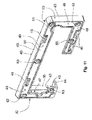
- FIG. 1 shows a possible aperture arrangement with various diaphragm bodies 10a, 10a ', which cover a functionally essential component 1a, 1b.
- the diaphragm bodies 10a, 10a ' are arranged against one another, wherein the diaphragm bodies 10a, 10a' are respectively adapted to the adjacent contour.
- a first diaphragm body 10a is arranged on a first functionally essential component, which is not explicitly shown. This first component is at least partially covered by the first diaphragm body, which will be discussed below.
- the second diaphragm body 10a ' is arranged on a further second functionally essential component 1b, which explicitly also not out FIG. 1 is apparent.
- the second component 1 b is partially covered by the second diaphragm body 10 a '.
- the first 10a and the second diaphragm body 10a ' have a plurality of corner regions 11, 12, wherein the corner regions 12 of the first diaphragm body 10a, which face the second component 1b, are formed as angular corner regions 12.
- the corner regions 11 of the first diaphragm body 10 a, which are remote from the second component 1 b, are formed as rounded corner regions 11, which also in FIG. 4 .
- FIG. 5 and FIG. 9 is shown.
- the first diaphragm body 10a ' is arranged on a movable door element 5.
- the second visor body 10 a is fixed to fixed wall elements 4.
- the functionally essential components 1a, 1b which are each covered by the diaphragm body 10a, 10a ', may have different technical functions.
- an axis of rotation is arranged in one of the functionally essential components 1a, 1b or a bolt which can provide a lock, etc.
- FIG. 1 is the diaphragm body 10a 'angled, in particular L-shaped equipped.
- the visor body 10 is designed for a functionally essential component 1, in particular for a fitting 1 or a corner fitting, wherein the visor body 10 has at least one aperture 20 and a support member 40, which relates to all embodiments.
- the diaphragm 20 has a plate element 23 with a front side 21 and a rear side 22.
- the plate element 23 can be fastened to a carrier element 40.
- the support member 40 has a cavity 42, are arranged in the fastening means 41, which serve to secure the support member 40 to functionally essential component 1, which, for example, in FIG. 3 .
- FIG. 8 or FIG. 13 is shown.
- the support member 40 has a wall 43 which is configured circumferentially and is like a frame.
- the support member 40 is designed with a bottom 44 which serves as a contact surface for the diaphragm 20, in particular the plate member 23 and for the functionally essential component. 1
- the carrier element has various wall sides 45, wherein in the exemplary embodiments only two opposite wall sides 45 have the fastening means 41.
- the bottom 44 has an inner side 47, which faces the functionally essential component 1. Furthermore, the bottom 44 has an outer side 48 which is associated or facing the diaphragm 20, in particular the plate element 23.
- the plate member 23, in particular the diaphragm 20 is and / or is positively and / or non-positively attached to the support member 40, which applies to all embodiments, with one exception in FIG.
- FIG. 11 is shown, in which the outer side 48 of the support member 40 has a recess 49 into which a connecting element 60, in particular an adhesive medium 50 can be introduced, so that upon contacting the panel 20, in particular of the plate member 23 with the outer side 48 of the support member 40 a Reliable cohesive connection can be produced. It is also conceivable that according to FIG. 11 In addition, a non-positive and / or positive connection between the carrier element 40 and the diaphragm 20, in particular the plate element 23 takes place.
- FIG. 2 FIG. 3 .
- FIG. 5 connecting elements 60 are shown, which are arranged on the panel 20, in particular on the plate element 23, to enter into a non-positive and / or positive connection with the carrier element 40.
- the connecting elements 60 can, for example via a Welding process to the panel 20, in particular to the plate member 23 are mounted, which in FIG. 12 and FIG. 14 is shown schematically, which will be discussed below.
- the visor body 10 has on the carrier element 40 counter-latching elements 63 which are formed as elastic wing elements.
- FIG. 10 shows by way of example for all embodiments, that the counter-latching element 63 also includes an opening 68, in which the latching element 61 engages.
- the latching element 61 has a thread, which is made of a plurality of recesses, whereby at least a positive connection with the wing elements 67 of the counter-latching element 63 takes place.
- the carrier element 40 has one or more recesses 51, which serve to create a free space for functional elements of the functionally essential component 1.
- the embodiment according to FIG. 2 . FIG. 7 . FIG. 8 . FIG. 6 corresponds essentially to the visor body 10 according to the figures described above, wherein the visor body 10 has a rectangular shape instead of an L-shape.
- the carrier element 40 is designed like a frame, wherein at least one point or a region is interrupted.
- FIG. 13 or FIG. 9 is shown.
- an element 1 of the functionally essential component 1 is shown, which protrudes through the opening of the carrier element 40.
- a stop element 6 is shown, which protrudes from the Aperture arrangement extends.
- This stop 6 may be a door stop, in particular for the door 5 according to FIG. 1 ,
- FIG. 8 shows a device with a visor body, in which only the support member 40 is shown, wherein the support member 40 is attachable to a functionally essential component 1.
- the functionally essential component 1 has a recess 8 into which the carrier element 40 extends with its bottom 44. This means that the geometry of the recess 8 is adapted to the geometry of the floor, so that a compact overall unit is created in the mounted state.
- the diaphragm body 10 is designed with a protective element 30 which laterally covers and protects the functionally essential component 1.
- the first diaphragm body 10a has a first diaphragm 20a on which a first frame element 40a is arranged.
- a second diaphragm body 10b comprises a second diaphragm 20b, on which a second frame element 40b is arranged.
- the first frame element 40a has the protective element 30, which extends in the manner of a projection in the direction of the second diaphragm body 10b, in particular of the second frame element 40b.
- the protective element 30 is below the second frame element 40b. It thus forms an asymmetric assembly with respect to both diaphragm body 10a, 10b.
- the carrier elements 40a, 40b are arranged at a distance from one another on the component 1 which is essential to the function.
- the protective element 30 also connects the first carrier element 40a with the second carrier element 40b.
- the circumferential wall 43 has an oblique course to the bottom 44. The oblique course is there on Support member 40 to see where the reference numeral 43 of the support member 40b shows.
- the carrier element 40a, 40 has a plurality of sides, which are formed by the wall 43, wherein a side 52 is formed as a protective side 52 having the protective element 30. This side 52 is also formed obliquely to the bottom 44.
- FIG. 12 and FIG. 14 it is shown how a panel 20 is made, in particular to arrange connecting elements 60 on the plate member 23 on the panel 20.
- the plate member 23 is prepared, wherein the plate member 23 is made without bending of a metal according to the illustrated embodiment.
- the connecting element 60 is arranged on the panel 20 by a welding process.
- the connecting element and the plate element 23 are melted in a step c), wherein a melt 64 is formed.
- the connecting element 60 is guided into the melt 64 of the plate element 23, which takes place in a step d).
- step c) which in FIG. 12b shown, there is a distance between the connecting element 60 and the plate member 23.
- a lifting device 65 is provided according to the invention, in order to bring about bringing the connecting element 60 to the plate member 23.
- the connecting element 60 has a tapered free end 62, and a thread 61, which is made of a plurality of recesses, whereby the thread 61 is thus formed of a plurality of locking elements 61, which in an attachment to the frame member 40 with the counter-locking elements 63 cooperate and thus form a reliable latching connection.
- the connecting element 60 has a collar element 66, which serves as a positioning aid in step d) (FIG. FIG. 12 ) acts.
- step a) by a welding process, the connecting element 60 on the flat plate member 20 arranged.
- step b attachment of the carrier element 40 to the panel 20 takes place.
- FIG. 14b shows that during step a), the step c) takes place, in which both the connecting element 60 and the plate member 23 are melted and in each case a melt 64 on the plate member 23 and connecting element 60 is formed.
- the connecting element 60 is guided into the melt 64 of the plate element 23 in a step d).
- step d) can already be carried out during step c).
- FIG. 11 shows that the support member 40 may have openings 46 associated with each fastener 41. These openings 46 are the result of a low cost injection molding process to efficiently provide the fasteners 41.
- FIG. 1 to FIG. 3 such as FIG. 13 show that by the device with two visor bodies 10 effectively a wall element 4 or a door element 5 can be accommodated. It has proved to be particularly advantageous that the ratio V of the material thickness M of the diaphragm 20 and the depth M + T of the diaphragm body 10 is approximately 5% ⁇ V ⁇ 35%, s.
- FIG. 3 The depth T denotes the depth of the carrier element 40. In this case, in FIG. 3 the aperture 20 and the support member 40 shown slightly spaced to represent the connecting elements 60 can.
- the panel 20 In an assembled state, the panel 20 abuts flush with the carrier element 40, so that the depth of the entire panel body 10 results from the depth M + T.
- the diaphragm 20 is made of a metal, according to the invention the following ratio V is proposed: 10% ⁇ V ⁇ 25%, which is particularly advantageous. If the diaphragm 20 is made of a glass, the ratio V 15% ⁇ V ⁇ 35% has proved to be particularly advantageous.
- the length of the protective element 30 is dimensioned so that different geometries can be covered on functionally essential components 1 by the visor body 10.
- the wall 43 of the second carrier element 40b has a length LR which extends in the direction of the first carrier element 40a.
- the length LS of the protective element 30 is advantageously 30% LR ⁇ LS ⁇ 200% LR.
- the protective member 30 has a widthwise extension B oriented perpendicular to the longitudinal extent L, where the widthwise extension B is 40% BS ⁇ B ⁇ 80% BS, where BS is the longitudinal extent of the protective side 52.
Abstract
Die Erfindung betrifft einen Blendenkörper (10) für ein funktionswesentliches Bauteil (1), insbesondere für einen Beschlag (1), mit einer zumindest als dekoratives Element wirkenden Blende (20) und einem Trägerelement (40), das mindestens ein Befestigungsmittel (41) aufweist, um eine Befestigung an das funktionswesentliche Bauteil (1) zu erzielen, wobei das Trägerelement (40) aus einem Kunststoffmaterial ausgebildet ist.The invention relates to a diaphragm body (10) for a functionally essential component (1), in particular for a fitting (1), with an aperture (20) acting at least as a decorative element and a carrier element (40) having at least one fastening means (41) in order to achieve an attachment to the functionally essential component (1), wherein the carrier element (40) is formed from a plastic material.
Description
Die Erfindung betrifft einen Blendenkörper für ein funktionswesentliches Bauteil, insbesondere für einen Beschlag.The invention relates to a visor body for a functionally essential component, in particular for a fitting.
Aus dem Stand der Technik sind Blenden bekannt, die insbesondere an Türbeschlägen und/oder Eckbeschlägen von Türen oder Wänden, insbesondere aus Glas, angeordnet sind. Diese Blenden sind aus Metall, Blech ausgebildet sowie häufig dreidimensional geformt, wobei die Formung bezüglich des Bauteils individuell anzupassen ist. Zudem hat sich nachteilig gezeigt, dass das Herstellungsverfahren derartiger Blenden schwierig, aufwendig und bezüglich des Gesamtherstellungsprozesses unflexibel ist. Neben dem relativ hohen Gewicht der Blende ist es nachteilig, dass häufig komplizierte Befestigungsverbindungen notwendig sind, um die Blende zuverlässig am funktionswesentlichen Bauteil, insbesondere am Beschlag anzuordnen.Apertures are known from the prior art, which are arranged in particular on door fittings and / or corner fittings of doors or walls, in particular of glass. These diaphragms are formed of metal, sheet metal and often shaped in three dimensions, wherein the shaping is to be adjusted individually with respect to the component. In addition, it has been disadvantageously shown that the production method of such panels is difficult, expensive and inflexible with respect to the overall production process. In addition to the relatively high weight of the panel, it is disadvantageous that often complicated fastening connections are necessary to reliably arrange the panel on the functionally essential component, in particular on the fitting.
Aufgabe der vorliegenden Erfindung ist es die voranstehend beschriebenen Nachteile zumindest teilweise zu beheben. Insbesondere ist es Aufgabe der vorliegenden Erfindung, eine kostengünstige und einfache Blende für ein funktionswesentliches Bauteil bereitzustellen, wobei zusätzlich eine einfache Montage erzielt werden kann.Object of the present invention is at least partially overcome the disadvantages described above. In particular, it is an object of the present invention to provide a cost-effective and simple diaphragm for a functionally essential component, wherein in addition a simple assembly can be achieved.
Die voranstehende Aufgabe wird gelöst durch einen erfindungsgemäßen Blendekörper, mit sämtlichen Merkmalen des Anspruches 1. WeitereThe above object is achieved by a blend body according to the invention, with all the features of
Merkmale und Details der Erfindung ergeben sich aus den Unteransprüchen, der Beschreibung und den Zeichnungen.Features and details of the invention will become apparent from the dependent claims, the description and the drawings.
Erfindungsgemäß ist ein Blendenkörper für ein funktionswesentliches Bauteil vorgesehen, insbesondere für einen Beschlag, mit einer zumindest als dekoratives Element wirkenden Blende und einem Trägerelement, das mindestens ein Befestigungsmittel aufweist, um eine Befestigung an das funktionswesentliche Bauteil zu erzielen, wobei das Trägerelement aus einem Kunststoffmaterial ausgebildet ist. Gemäß der Erfindung wird ein Trägerelement vorgeschlagen, welches einfach auf unterschiedliche Geometrien des funktionswesentlichen Bauteils anpassbar ist, wobei das Trägerelement aus einem Kunststoff ausgeführt ist, wodurch das Gesamtgewicht wesentlich reduziert werden kann. Beispielsweise kann es sich bei dem Trägerelement um ein Kunststoffspritzgussteil oder ein 3D-druckteil handeln. Das Trägerelement kann ein oder mehrere Befestigungsmittel aufweisen, die dafür geeignet sind eine zuverlässige Fixierung des Blendenkörpers am funktionswesentlichen Bauteil zu erzielen. Die Blende ist insbesondere für einen Beschlag für Glastüren oder Glaswände einsetzbar.According to the invention, a visor body is provided for a functionally essential component, in particular for a fitting, with an aperture acting at least as a decorative element and a carrier element which has at least one fastening means in order to achieve an attachment to the functionally essential component, wherein the carrier element is formed from a plastic material is. According to the invention, a support element is proposed, which is easily adaptable to different geometries of the functionally essential component, wherein the support element is made of a plastic, whereby the total weight can be substantially reduced. For example, the carrier element may be a plastic injection-molded part or a 3D-printing part. The carrier element may have one or more attachment means which are suitable for achieving a reliable fixation of the visor body on the functionally essential component. The bezel is particularly suitable for fitting for glass doors or glass walls.
Die Ausbildung des Trägermaterials aus Kunststoff schließt eine nur teilweise Ausbildung aus Kunststoff mit ein. So kann z. B. auf dem Kunststoff eine Oberflächenschicht, z. B. ein Lack oder ein Laminat angeordnet sein. Zusätzlich oder alternativ kann das Trägermaterial Verstärkungsmaterial, z. B. Carbonfasern, aufweisen. In einer besonders bevorzugten Ausführungsform ist das Trägermaterial vollständig aus Kunststoff ausgebildet.The formation of the carrier material made of plastic includes only a partial training of plastic. So z. B. on the plastic, a surface layer, for. As a paint or a laminate may be arranged. Additionally or alternatively, the carrier material reinforcing material, for. B. carbon fibers have. In a particularly preferred embodiment, the carrier material is completely formed from plastic.
Vorteilhafterweise kann eine Blende, die für verschiedene funktionswesentliche Bauteile gleich ausgestaltet ist, zum Einsatz kommen, wobei in Abhängigkeit von der Geometrie des funktionswesentlichen Bauteils ein entsprechendes aus Kunststoff ausgeführtes Trägerelement eingesetzt wird, welches mit der Blende verbunden ist. Vorteilhafterweise setzt sich der Blendenkörper aus zumindest der dekorativen Blende und dem Trägerelement zusammen. Die Blende sowie das Trägerelement können beispielsweise aus einem gemeinsamen Körper ausgeführt sein, das bedeutet, dass Blende und Trägerelement ein monolithisches, gemeinsames Bauteil bilden. Folglich kann dieses Bauteil, welches aus Kunststoff ausgeführt ist, wesentlich bezüglich der Gewichtsreduktion beitragen. Entsprechende Befestigungsmittel sorgen dafür, dass der Blendenkörper zügig ohne wesentlichen Montageaufwand an das funktionswesentliche Bauteil befestigt werden kann.Advantageously, a diaphragm, which is designed the same for different components essential to the function, is used come, depending on the geometry of the functionally essential component, a corresponding made of plastic carrier element is used, which is connected to the diaphragm. Advantageously, the visor body is composed of at least the decorative panel and the carrier element. The panel as well as the carrier element can be designed, for example, from a common body, which means that the panel and carrier element form a monolithic, common component. Consequently, this component, which is made of plastic, contribute significantly to the weight reduction. Corresponding fastening means ensure that the visor body can be fastened quickly to the functionally essential component without substantial assembly effort.
Ebenfalls ist es denkbar, dass unterschiedliche Befestigungsmittel, insbesondere an der Blende und/oder am Trägerelement angeordnet sind, die in Abhängigkeit von unterschiedlichen funktionswesentlichen Bauteilen ihre Befestigungsfunktion begründen. Das bedeutet, dass ein Blendenkörper standardisiert werden kann, um an unterschiedliche Geometrien von funktionswesentlichen Bauteilen angeordnet zu werden. Vorteilhafterweise können die Befestigungsmittel an unterschiedlichen Positionen am Blendenkörper angeordnet sein, wobei ihre Funktion als Befestigungsmittel in Abhängigkeit von der Geometrie des funktionswesentlichen Bauteils benötigt wird oder nicht.It is also conceivable that different fastening means, in particular on the panel and / or on the carrier element are arranged, which justify their attachment function in dependence on different functionally essential components. This means that a visor body can be standardized in order to be arranged on different geometries of functionally essential components. Advantageously, the fastening means may be arranged at different positions on the visor body, wherein their function as a fastening means depending on the geometry of the functionally essential component is needed or not.
Es kann vorteilhaft sein, dass die Blende sowie das Trägerelement aus unterschiedlichen Bauteilen ausgeführt sind, wobei das Trägerelement über Verbindungselemente an der Blende befestigt ist. Auch in diesem Ausführungsbeispiel kann eine Blende, die für verschiedene funktionswesentliche Bauteile gleich ausgestaltet ist, zum Einsatz kommen, die am Trägerelement befestigt ist, wobei zum Beispiel das Trägerelement mindestens ein Befestigungsmittel aufweist, um den Blendenkörper am funktionswesentlichen Bauteil zu fixieren.It may be advantageous that the diaphragm and the carrier element are made of different components, wherein the carrier element is fastened to the diaphragm via connecting elements. Also in this embodiment, a diaphragm, which is designed the same for different components essential to the function, are used come, which is fixed to the support element, wherein, for example, the support member has at least one fastening means to fix the visor body on the functionally essential component.
Vorteilhaft ist es weiter, wenn das Befestigungsmittel mit dem Trägerelement ein gemeinsames, monolithisches Bauteil bildet und/oder das Befestigungsmittel mit dem Trägerelement einstückig miteinander verbunden ist. Somit kann die Anzahl an Bauteilen an einem Blendenkörper reduziert werden, wobei es sich vorteilhafterweise gezeigt hat, dass hierdurch eine einfache Montage des Blendenkörpers an das funktionswesentliche Bauteil erzielt werden kann. Zudem lassen sich die Herstellungskosten reduzieren, wenn das Befestigungsmittel am Trägerelement integriert ist.It is also advantageous if the fastening means with the carrier element forms a common, monolithic component and / or the fastening means is integrally connected to the carrier element. Thus, the number of components can be reduced to a visor body, wherein it has been shown advantageously that thereby a simple assembly of the visor body can be achieved to the functionally essential component. In addition, the manufacturing costs can be reduced if the fastening means is integrated on the carrier element.
Vorteilhaft ist es ebenfalls, wenn das Befestigungsmittel ein Rastelement und/oder ein Clipselement aufweist. Zum einen lassen sich derartige Befestigungsmittel einfach herstellen, insbesondere als Kunststoffspritzgussbauteil. Ein weiterer Vorteil ist, dass derartige Befestigungsmittel besonders eine einfache Montage begünstigen.It is also advantageous if the fastening means has a latching element and / or a clip element. On the one hand, such fastening means can be produced easily, in particular as a plastic injection-molded component. Another advantage is that such fastening means favor a simple assembly.
Zudem ist es denkbar, dass die Blende aus einem Material ausgebildet ist, das aus Metall und/oder Glas und/oder Holz und/oder Leder und/oder Kunststoff ausgeführt ist. Somit kann ein Blendenkörper gemäß der Erfindung bereitgestellt werden, der unterschiedlichsten Designwünschen genügen kann. Eine metallische Blende zeichnet sich durch ihre hohe Stabilität aus, wobei das Metall zudem eine erhöhte Schutzfunktion für das funktionswesentliche Bauteil darstellt. Wird der Blendenkörper an Glaswänden/Glastüren eingesetzt, kann eine aus Glas ausgeführte Blende Sinn machen, wodurch ein einheitliches Gesamtbild erzielbar ist. Die aus Kunststoff ausgeführte Blende kann unterschiedliche Designausführungen aufweisen, insbesondere aus einer oder diversen Farben ausgebildet sein. In einer möglichen Ausgestaltung einer aus Kunststoff ausgeführten Blende kann erfindungsgemäß vorgesehen sein, dass die Oberfläche der Blende beschichtet ist, wobei die Farbe und/oder das Material der Beschichtung gemäß dem Einsatzgebiet und/oder den Kundenwünschen entsprechend angepasst sein kann.In addition, it is conceivable that the diaphragm is formed from a material which is made of metal and / or glass and / or wood and / or leather and / or plastic. Thus, a visor body can be provided according to the invention, which can satisfy a variety of design needs. A metallic diaphragm is characterized by its high stability, wherein the metal also represents an increased protective function for the functionally essential component. If the visor body is used on glass walls / glass doors, an aperture made of glass can make sense, so that a uniform overall picture can be achieved. The made of plastic panel can be different Have design designs, in particular be formed of one or several colors. In a possible embodiment of an aperture made of plastic can be inventively provided that the surface of the panel is coated, the color and / or the material of the coating according to the application and / or the customer can be adjusted accordingly.
Zudem kann die Erfindung mitumfassen, dass die Blende ein ebenes Plattenelement aufweist und/oder ist, das eine Frontseite und eine Rückseite aufweist, wobei die Rückseite dem Trägerelement zugewandt ist, insbesondere die Rückseite mit dem Trägerelement befestigt ist. Beispielsweise kann über Verbindungselemente, die an der Blende und/oder am Plattenelement und/oder am Trägerelement vorgesehen sind, eine Befestigung der Blende/Plattenelement mit dem Trägerelement wirksam erzielt werden.In addition, the invention may include that the panel has and / or is a flat plate element which has a front side and a rear side, wherein the rear side faces the carrier element, in particular the rear side is fastened to the carrier element. For example, can be effectively achieved by means of connecting elements which are provided on the panel and / or on the plate element and / or on the carrier element, a fastening of the panel / plate element with the support element.
Vorteilhaft ist es ebenfalls, dass das Trägerelement mit einer Kavität ausgebildet ist, in die zumindest teilweise das funktionswesentliche Bauteil aufnehmbar ist, wobei insbesondere die Kavität durch eine Wandung, insbesondere umlaufende Wandung, begrenzt ist. Ferner kann die Kavität durch einen Boden des Trägerelementes begrenzt sein. Ein Vorteil der Kavität ist es, dass eine kompakte Gesamtanordnung des Blendenkörpers mit dem funktionswesentlichen Bauteil geschaffen werden kann. Vorteilhafterweise befindet sich das funktionswesentliche Bauteil in zusammengebautem Zustand zumindest teilweise in der Kavität, insbesondere wird es dort in der Kavität aufgenommen. Die Wandung verdeckt zumindest teilweise das funktionswesentliche Bauteil, die somit als Sichtschutz bezüglich des funktionswesentlichen Bauteils dient. Somit ist es denkbar, dass das Trägerelement als eine Art Gehäuse für das funktionswesentliche Bauteil dient, das unter anderem eine gewisse Schutzfunktion aufweisen kann.It is also advantageous that the carrier element is formed with a cavity into which at least partially the functionally essential component is receivable, wherein in particular the cavity is bounded by a wall, in particular circumferential wall. Furthermore, the cavity may be delimited by a bottom of the carrier element. An advantage of the cavity is that a compact overall arrangement of the visor body can be created with the functionally essential component. Advantageously, the functionally essential component is in the assembled state at least partially in the cavity, in particular it is received there in the cavity. The wall covers at least partially the functionally essential component, which thus serves as a visual screen with respect to the functionally essential component. Thus, it is conceivable that the carrier element as a kind of housing for the functionally essential component is used, which may have, inter alia, a certain protective function.
In einer die Erfindung verbessernden Maßnahme kann es vorgesehen sein, dass das Trägerelement derart an der Blende angeordnet ist, dass das Trägerelement von außen sichtbar ist. Hierbei ist es denkbar, dass das Trägerelement an mindestens einer Seite des Blendenkörpers, bevorzugt an mindestens zwei Seite des Blendenkörpers, besonders bevorzugt an mindestens drei Seiten des Blendenkörpers sichtbar ist. Auch kann das Trägerelement an vier Seiten des Blendenkörpers sichtbar sein. Bevorzugt ist das Trägerelement an einer Vorderseite des Blendenkörpers unsichtbar. Insbesondere kann eine Frontseite der Blende die Vorderseite des Blendenkörpers bilden. Besonders bevorzugt können die Seiten der Blenan den Seiten des Blendenkörpers sichtbar sein.In a measure improving the invention, provision can be made for the carrier element to be arranged on the panel in such a way that the carrier element is visible from the outside. In this case, it is conceivable for the carrier element to be visible on at least one side of the visor body, preferably on at least two sides of the visor body, particularly preferably on at least three sides of the visor body. Also, the support member may be visible on four sides of the visor body. The carrier element is preferably invisible on a front side of the visor body. In particular, a front side of the diaphragm can form the front side of the diaphragm body. Most preferably, the sides of the blenan may be visible on the sides of the visor body.
Insbesondere kann die Blende derart am Trägerelement angeordnet ist, dass der Boden durch die Blende verdeckt ist und/oder die Wandung im Montagezustand am funktionswesentlichen Bauteil von außen zumindest teilweise sichtbar ist. Ein Vorteil hierbei ist, dass hinsichtlich der Blende Material einspart werden kann, da zwischen der Blende und dem funktionswesentlichen Bauteil das Trägerelement positioniert ist und somit die Blende nicht bis zum funktionswesentlichen Bauteil sich erstrecken muss. Ein zusätzlicher Effekt ist, dass für den Betrachter ein schwebender Eindruck der Blende geschaffen wird. Der schwebende Eindruck wird dadurch verstärkt, dass die Blende und das Trägerelement sich in der Farbe und/oder dem Material unterscheiden.In particular, the diaphragm can be arranged on the carrier element such that the bottom is covered by the diaphragm and / or the wall is at least partially visible from the outside in the assembled state on the functionally essential component. One advantage here is that material can be saved with regard to the diaphragm since the carrier element is positioned between the diaphragm and the functionally essential component and thus the diaphragm does not have to extend to the functionally essential component. An additional effect is that the viewer is provided with a hovering impression of the aperture. The floating impression is enhanced by the fact that the aperture and the support element differ in color and / or material.
Vorteilhaft ist es ebenfalls, dass der Boden als Anlageelement für die Blende dient. Die Wandung kann zumindest teilweise das funktionswesentliche Bauteil von außen abschirmen und bedecken.It is also advantageous that the bottom serves as a contact element for the aperture. The wall can at least partially shield and cover the functionally essential component from the outside.
Des Weiteren kann die Erfindung mitumfassen, dass die Blende und das Trägerelement derart ausgeführt sind, dass der Blendenkörper zumindest einen abgerundeten Eckbereich aufweist und/oder zumindest einen eckigen Eckbereich aufweist. Der abgerundete Eckbereich hat den Vorteil eine mögliche Verletzungsgefahr auszuschließen. Der eckige Eckbereich, der vorzugsweise innenliegend an der Blende angeordnet ist und somit ebenfalls keine Verletzungsgefahr darstellt, hat den Vorteil, dass bei der Herstellung möglichst wenig Materialverlust entsteht. Im Gegensatz zu dem eckigen Eckbereich befinden sich der oder die abgerundeten Eckbereiche außenliegend an der Blende. Unter "innenliegend" wird insbesondere ein Eckbereich verstanden, der dazu ausgebildet ist, einer Kante der Wand oder der Tür zugewandt angeordnet zu werden. Hierbei kann sich insbesondere ein weiterer Blendenkörper an den Eckbereich anschließen. Unter "außenliegend" wird insbesondere ein Eckbereich verstanden, der dazu ausgebildet ist, von einer Kante der Wand oder der Tür abgewandt angeordnet zu werden. Hierbei schließt sich insbesondere kein weiterer Blendenkörper an den Eckbereich an.Furthermore, the invention can mitumfassen that the panel and the support member are designed such that the visor body has at least one rounded corner region and / or at least has an angular corner region. The rounded corner area has the advantage of eliminating a possible risk of injury. The angular corner region, which is preferably arranged on the inside of the panel and thus also does not pose a risk of injury, has the advantage that as little as possible material loss occurs during manufacture. In contrast to the angular corner area, the rounded corner areas are located on the outside of the panel. By "internal" is meant in particular a corner region, which is designed to be disposed facing an edge of the wall or the door. In this case, in particular, another diaphragm body can connect to the corner region. By "outside" is meant in particular a corner region, which is designed to be arranged facing away from an edge of the wall or the door. In particular, no further diaphragm body adjoins the corner region.
Vorteilhaft ist darüber hinaus, dass das Befestigungsmittel derart am Trägerelement ausgebildet ist, dass das Befestigungsmittel von außen unsichtbar ist, insbesondere dass das Befestigungsmittel in der Kavität sich befindet. Ein wesentlicher Vorteil ist, dass hierdurch ein Manipulationsschutz wirksam am Blendenkörper installiert ist. Zusätzlich hat sich gezeigt, dass durch das nicht sichtbare Befestigungsmittel ein elegantes Design für den Blendenkörper geschaffen werden kann.It is also advantageous that the fastening means is formed on the carrier element such that the fastening means is invisible from the outside, in particular that the fastening means is located in the cavity. A significant advantage is that this tamper protection is effectively installed on the visor body. In addition, it has been shown that an elegant design for the visor body can be created by the non-visible fastener.
Des Weiteren sieht ein erfindungsgemäßer Blendenkörper vor, dass die Wandung das mindestens eine Befestigungsmittel aufweist. Als nützlich hat es sich erwiesen, das mindestens eine Befestigungsmittel an der Wandung, insbesondere an der umlaufenden Wandung vorzusehen, da hierdurch begünstigte Befestigungsmöglichkeiten zum funktionswesentlichen Bauteil geschaffen werden.Furthermore, an inventive diaphragm body provides that the wall has the at least one fastening means. It has proven to be useful, the at least one fastener on the Wall, in particular to provide on the circumferential wall, as this favored mounting options are created to functionally essential component.
Zudem umfasst die Erfindung, dass das Trägerelement mehrere Befestigungsmittel aufweist, wobei die Befestigungsmittel derart ausgebildet sind, dass zumindest zwei Befestigungsmittel im Montagezustand am funktionswesentlichen Bauteil sich in ihrer Haltekraft am funktionswesentlichen Bauteil unterscheiden. Hierdurch wird eine einfache Befestigung des Blendenkörpers zum funktionswesentlichen Bauteil geschaffen. Zudem kann mit den erwähnten Merkmalen ein sicherer Halt des Blendenkörpers am funktionswesentlichen Bauteil erzielt werden. Beispielsweise kann es vorgesehen sein, dass ein Befestigungsmittel mit einer größeren Haltekraft eingesetzt wird, wobei der Monteur dieses Befestigungsmittel zunächst zum Einsetzen des Blendenkörpers an das funktionswesentliche Bauteil nutzt. Ist die gewünschte Position des Blendenkörpers am funktionswesentlichen Bauteil bezüglich des genannten Befestigungsmittels geschaffen, kann der restliche Teil des Blendenkörpers zum funktionswesentlichen Bauteil bewegt und/oder geschwenkt werden, wobei das Befestigungsmittel mit der höheren Haltekraft stets kontaktierend am funktionswesentlichen Bauteil verbleibt. Ein zweites Befestigungsmittel mit einer geringeren Haltekraft wird bei der Überführung des Blendenkörpers in seine Endmontageposition elastisch verformt. Ist die Endmontagestellung des Blendenkörpers erreicht, federt das Befestigungsmittel mit der geringeren Haltekraft zurück in Richtung seiner Grundstellung, wobei beide Befestigungsmittel, das mit der größeren und das mit der kleineren Haltekraft für einen sicheren Halt des Blendenkörpers am funktionswesentlichen Bauteil sorgen.In addition, the invention comprises that the carrier element has a plurality of fastening means, wherein the fastening means are formed such that at least two fastening means in the assembled state on the functionally essential component differ in their holding force on the functionally essential component. As a result, a simple attachment of the visor body is created to functionally essential component. In addition, with the mentioned features a secure hold of the visor body can be achieved on the functionally essential component. For example, it can be provided that a fastening means with a larger holding force is used, wherein the fitter first uses this fastening means for inserting the visor body to the functionally essential component. If the desired position of the visor body created on the functionally essential component with respect to said fastener, the remaining part of the visor body can be moved to the functionally essential component and / or pivoted, the fastener always remains contacting the functionally essential component with the higher holding force. A second fastener with a lower holding force is elastically deformed during the transfer of the visor body in its final assembly position. Is the final assembly position of the visor body reached, the fastener springs with the lower holding force back towards its normal position, both fasteners that provide the larger and the smaller holding power for a secure fit of the visor body on the functionally essential component.
Zudem kann es vorteilhaft sein, dass das mindestens eine Befestigungsmittel in die Kavität ragt. Somit wird eine kompakte Bauweise des Blendenkörpers erzielt, wobei auch ein Designvorteil zu erzielen ist, da die Befestigungsmittel von außen unsichtbar sind.In addition, it may be advantageous that the at least one fastening means projects into the cavity. Thus, a compact design of the visor body is achieved, whereby a design advantage can be achieved, since the fasteners are invisible from the outside.
Vorteilhaft ist es ebenfalls, dass das Trägerelement rahmenartig ausgebildet ist. Eine derartige geometrische Ausgestaltung des Trägerelementes begünstigt, dass an diversen Seiten des funktionswesentlichen Bauteils eine zuverlässige Befestigungswirkung erzielt wird. Vorteilhafterweise ist die Geometrie des Trägerelementes der Geometrie des funktionswesentlichen Bauteils angepasst.It is also advantageous that the support element is formed like a frame. Such a geometric design of the carrier element favors that a reliable fastening effect is achieved on various sides of the functionally essential component. Advantageously, the geometry of the carrier element of the geometry of the functionally essential component is adjusted.
Ebenfalls kann die Erfindung mitumfassen, dass der Verlauf des Trägerelements der äußeren Kontur der Blende angepasst ist, insbesondere dass die Blende eine geometrische Form aufweist, die rechteckförmig oder quadratisch oder winklig oder L-förmig ist. Zudem ist es denkbar, dass der Verlauf des Trägerelementes zumindest an einer Seite unterbrochen ist. Vorteilhaft ist, dass es innerhalb des funktionswesentlichen Bauteils Funktionselemente geben kann, die aus dem Blendenkörper zumindest teilweise herausragen können. Um dieses zu ermöglichen, kann es vorteilhaft sein, dass das Trägerelement zumindest zu einer Seite offen ausgeführt ist, insbesondere an einer Seite unterbrochen ist.The invention can also encompass that the course of the carrier element is adapted to the outer contour of the diaphragm, in particular that the diaphragm has a geometric shape that is rectangular or square or angular or L-shaped. In addition, it is conceivable that the course of the carrier element is interrupted at least on one side. It is advantageous that it can give functional elements within the functionally essential component, which can protrude from the visor body at least partially. To make this possible, it may be advantageous for the carrier element to be open at least on one side, in particular interrupted on one side.
Ein weiterer Vorteil der Erfindung kann vorsehen, dass die Wandung mindestens vier Wandungsseiten aufweist, wobei insbesondere mindestens zwei gegenüberliegende Wandungsseiten die Befestigungsmittel aufweisen, insbesondere nur zwei Wandungsseiten die Befestigungsmittel aufweisen. Überraschenderweise hat sich gezeigt, dass bereits eine zuverlässige Befestigungswirkung erzielt werden kann, wenn nur an zwei Wandungsseiten Befestigungsmittel vorgesehen sind.A further advantage of the invention can provide that the wall has at least four wall sides, wherein in particular at least two opposite wall sides have the fastening means, in particular only two wall sides have the fastening means. Surprisingly, it has been shown that a reliable fastening effect can already be achieved if fastening means are provided only on two sides of the wall.
Vorteilhafterweise können entlang der Längserstreckung des Blendenkörpers die Befestigungsmittel angeordnet sein. Zudem ist es denkbar, dass jedem Befestigungsmittel eine Öffnung am Trägerelement zugeordnet ist, wobei insbesondere der Boden die Öffnung aufweist. Die Öffnungen entstehen durch ein einfaches Spritzgussverfahren, wodurch das Herstellungsverfahren für das Trägerelement vereinfacht wird. Somit sind keine Schieber im Werkzeug des Spritzgussverfahrens erforderlich.Advantageously, the fastening means can be arranged along the longitudinal extension of the visor body. In addition, it is conceivable that each fastening means is associated with an opening on the carrier element, wherein in particular the bottom has the opening. The openings are formed by a simple injection molding process, whereby the manufacturing process for the support element is simplified. Thus, no slides in the mold of the injection molding process are required.
Ebenfalls kann die Erfindung mitumfassen, dass die Blende am Trägerelement form- und/oder kraft- und/oder stoffschlüssig verbunden ist, insbesondere mindestens ein von außen unsichtbares Verbindungelement dafür sorgt, dass eine zuverlässige Befestigung zwischen der Blende und dem Trägerelement vorliegt. Neben einer Rastverbindung und/oder Clipsverbindung zwischen dem Trägerelement und der Blende ist alternativ oder zusätzlich ein Klebemedium als Verbindungselement denkbar. Es hat sich als vorteilhaft erwiesen, eine gute Befestigungswirkung dann zu erzielen, wenn die Blende aus einem Glas ausgeführt ist, und ein Klebemedium als Verbindungselement zwischen Blende und Trägerelement zu verwenden. Ist die Blende aus einem Metall, kann es vorteilhaft sein, eine kraft- und/oder formschlüssige Verbindung zwischen Blende und dem Trägerelement einzusetzen.Likewise, the invention can mitumfassen that the panel on the support member positively and / or positively and / or materially connected, in particular at least one invisible from the outside connecting element ensures that a reliable attachment between the panel and the support member is present. In addition to a latching connection and / or clip connection between the carrier element and the diaphragm, alternatively or additionally an adhesive medium is conceivable as a connecting element. It has proved to be advantageous to achieve a good fastening effect when the panel is made of a glass, and to use an adhesive medium as a connecting element between the panel and the support element. If the panel is made of a metal, it may be advantageous to use a non-positive and / or positive connection between the panel and the carrier element.
Weitere Vorteile, Merkmale und Einzelheiten der Erfindung ergeben sich aus der nachfolgenden Beschreibung, in der unter Bezugnahme auf die Zeichnungen mehrere Ausführungsbeispiele der Erfindung im Einzelnen beschrieben sind. Dabei können die in den Ansprüchen und in der Beschreibung erwähnten Merkmale jeweils einzeln für sich oder in beliebiger Kombination erfindungswesentlich sein. Es zeigen:
Figur 1- eine schematisch dargestellte Blendenanordnung mit mehreren aneinander angeordneten Blendenkörpern,
- Figur 2
- eine Blendenanordnung mit einem funktionswesentlichen Bauteil und daran angeordneten Blendenkörpern,
Figur 3- eine schematische Ansicht eines Blendekörpers, in dem ein funktionswesentliches Bauteil angeordnet ist,
Figur 4- ein Blendenkörper mit einer Blende und einem Trägerelement
Figur 5- der Blendenkörper gemäß
Figur 4 in einer weiteren Ansicht, Figur 6- ein weiteres Ausführungsbeispiel eines Trägerelementes, das in einen Blendenkörper der
Figuren 1 - 5 einsetzbar ist, - Figur 7
- das
Trägerelement gemäß Figur 6 in einer weitere Darstellung, Figur 8- ein weiteres Ausführungsbeispiel mit einem funktionswesentlichen Bauteil, an dem ein Trägerelement befestigbar ist,
- Figur 9
- ein weiteres Ausführungsbeispiel einer Blendenanordnung mit zwei Blendenkörpern und einem funktionswesentlichen Bauteil, das durch die Blendenkörper umfasst ist,
Figur 10- ein weiteres Ausführungsbeispiel eines Trägerelementes mit einem Schutzelement,
Figur 11- ein weiteres Ausführungsbeispiel eines Trägerelementes,
Figur 12- Verfahrensschritte zur stoffschlüssigen Befestigung eines Verbindungselementes an einer Blende, insbesondere an einem Plattenelement,
- Figur 13
- eine weitere Darstellung einer Blendenanordnung mit zwei Blendenkörpern, die ein funktionswesentliches Bauteil umschließen und
- Figur 14
- eine schematische Verfahrensdarstellung zur Herstellung eines Blendenkörpers.
- FIG. 1
- a schematically illustrated diaphragm arrangement with a plurality of diaphragm bodies arranged on one another,
- FIG. 2
- a diaphragm arrangement with a functionally essential component and diaphragm bodies arranged thereon,
- FIG. 3
- a schematic view of a visor body, in which a functionally essential component is arranged,
- FIG. 4
- a visor body with a diaphragm and a support element
- FIG. 5
- the visor body according to
FIG. 4 in another view, - FIG. 6
- a further embodiment of a carrier element, which in an aperture body of
Figures 1 - 5 can be used, - FIG. 7
- the carrier element according to
FIG. 6 in another illustration, - FIG. 8
- a further embodiment with a functionally essential component, on which a carrier element can be fastened,
- FIG. 9
- FIG. 2 shows a further exemplary embodiment of a diaphragm arrangement with two diaphragm bodies and a functionally essential component which is encompassed by the diaphragm bodies, FIG.
- FIG. 10
- a further embodiment of a carrier element with a protective element,
- FIG. 11
- a further embodiment of a carrier element,
- FIG. 12
- Method steps for materially fastening a connecting element to a panel, in particular to a panel element,
- FIG. 13
- a further illustration of a diaphragm arrangement with two diaphragm bodies which enclose a functionally essential component and
- FIG. 14
- a schematic process diagram for the production of a visor body.
Elemente und Merkmale mit gleicher Funktion und Wirkungsweise sind in den
Gemäß sämtlicher Ausführungsbeispiele ist der Blendenkörper 10 für ein funktionswesentliches Bauteil 1, insbesondere für einen Beschlag 1 oder einen Eckbeschlag ausgelegt, wobei der Blendenkörper 10 zumindest eine Blende 20 sowie ein Trägerelement 40 aufweist, welches sich auf sämtliche Ausführungsbeispiele bezieht. Gemäß
Das Trägerelement 40 weist eine Wandung 43 auf, die umlaufend ausgestaltet ist und rahmenartig ist. Zudem ist das Trägerelement 40 mit einem Boden 44 ausgeführt, der als Anlagefläche für die Blende 20, insbesondere das Plattenelement 23 dient und für das funktionswesentliche Bauteil 1.The
Das Trägerelement weist diverse Wandungsseiten 45 auf, wobei in den Ausführungsbeispielen nur zwei gegenüberliegende Wandungsseiten 45 die Befestigungsmittel 41 aufweisen. Der Boden 44 weist eine Innenseite 47 auf, die dem funktionswesentlichen Bauteil 1 zugewandt ist. Des Weiteren weist der Boden 44 eine Außenseite 48 auf, die der Blende 20, insbesondere dem Plattenelement 23 zugeordnet bzw. zugewandt ist. Das Plattenelement 23, insbesondere die Blende 20 wird und/oder ist form- und/oder kraftschlüssig mit dem Trägerelement 40 befestigt, welches für sämtliche Ausführungsbeispiele gilt, wobei eine Ausnahme in
In
Der Blendenkörper 10 weist am Trägerelement 40 Gegenrastelemente 63 auf, die als elastische Flügelelemente ausgebildet sind.
Wie aus sämtlichen Darstellungen der Figuren ersichtlich ist, weist das Trägerelement 40 eine oder mehrere Aussparungen 51 auf, die dazu dienen einen Freiraum für Funktionselemente des funktionswesentlichen Bauteils 1 zu schaffen. Das Ausführungsbeispiel gemäß
In der
In
Die Länge des Schutzelementes 30 ist so dimensioniert, dass unterschiedliche Geometrien an funktionswesentlichen Bauteilen 1 durch den Blendenkörper 10 abgedeckt werden können. Gemäß
- 11
- funktionswesentliches Bauteil, Beschlagfunctionally essential component, fitting
- 1a1a
- Beschlagfitting
- 1b1b
- Beschlagfitting
- 22
- Beschlagelementfitting element
- 2a2a
- Beschlagelementfitting element
- 2b2 B
- Beschlagelementfitting element
- 33
- Befestigungselementfastener
- 44
- Wandelementwall element
- 55
- Türelementdoor element
- 66
- Anschlagattack
- 88th
- Vertiefungdeepening
- 1010
- Blendenkörpervisor body
- 10a10a
- Blendenkörpervisor body
- 10a'10a '
- Blendenkörpervisor body
- 10b10b
- Blendenkörpervisor body
- 1111
- Eckbereich, abgerundetCorner area, rounded off
- 1212
- Eckbereich, eckigCorner area, angular
- 2020
- Blende, PlattenelementAperture, plate element
- 20a20a
- Blendecover
- 20b20b
- Blendecover
- 2121
- Frontseitefront
- 21a21a
- Frontseitefront
- 21b21b
- Frontseitefront
- 2222
- Rückseiteback
- 22a22a
- Rückseiteback
- 22b22b
- Rückseiteback
- 2323
- Plattenelementpanel member
- 3030
- Schutzelementprotection element
- 4040
- Trägerelementsupport element
- 40a40a
- erstes Trägerelementfirst carrier element
- 40b40b
- zweites Trägerelementsecond carrier element
- 4141
- Befestigungsmittelfastener
- 4242
- Kavitätcavity
- 4343
- umlaufende Wandungcircumferential wall
- 4444
- Bodenground
- 4545
- Wandungsseitewall side
- 4646
- Öffnungopening
- 4747
- Innenseiteinside
- 4848
- Außenseiteoutside
- 4949
- Vertiefungdeepening
- 5050
- Klebemediumadhesive medium
- 5151
- Aussparungrecess
- 5252
- Schutzseiteprotection page
- 5353
- Seitepage
- 6060
- Verbindungselementconnecting element
- 6161
- Rastelement, Gewinde, VertiefungLocking element, thread, recess
- 6262
- freies Ende, verjüngtfree end, rejuvenated
- 6363
- GegenrastelementCounter-locking element
- 6464
- Schmelzemelt
- 6565
- Hubvorrichtunglifting device
- 6666
- Kragenelementcollar element
- 6767
- Flügelelementwing element
- 6868
- Öffnungopening
Claims (19)
einer zumindest als dekoratives Element wirkenden Blende (20) und einem Trägerelement (40), das mindestens ein Befestigungsmittel (41) aufweist, um eine Befestigung an das funktionswesentliche Bauteil (1) zu erzielen, wobei das Trägerelement (40) aus einem Kunststoffmaterial ausgebildet ist.Shutter body (10) for a functionally essential component (1), in particular for a fitting (1), with
an aperture (20) acting at least as a decorative element and a carrier element (40) having at least one attachment means (41) for attachment to the functionally essential component (1), wherein the carrier element (40) is formed from a plastic material ,
dadurch gekennzeichnet,
dass das Befestigungsmittel (41) mit dem Trägerelement (40) ein gemeinsames, monolithisches Bauteil bildet und/oder das Befestigungsmittel (41) mit dem Trägerelement (40) einstückig miteinander verbunden ist.An aperture body (10) according to claim 1,
characterized,
that the fastening means (41) to the carrier element (40) forms a common, monolithic component and / or the fastening means (41) to the carrier element (40) is integrally connected.
dadurch gekennzeichnet,
dass das Befestigungsmittel (41) ein Rastelement (41) und/oder ein Clipselement (41) aufweist.Shutter body (10) according to claim 1 or 2,
characterized,
that the fastening means (41) comprises a detent element (41) and / or a clip element (41).
dadurch gekennzeichnet,
dass die Blende (20) aus einem Material ausgebildet ist, das aus Metall und/oder Glas und/oder Holz und/oder Leder und/oder Kunststoff ausgeführt ist.Shutter body (10) according to one of the preceding claims,
characterized,
that the panel (20) is formed from a material which is made of metal and / or glass and / or wood and / or leather and / or plastic.
dadurch gekennzeichnet,
dass die Blende (20) ein ebenes Plattenelement (23) aufweist und/oder ist, das eine Frontseite (21) und eine Rückseite (22) aufweist, wobei die Rückseite (22) dem Trägerelement (40) zugewandt ist, insbesondere die Rückseite (22) mit dem Trägerelement (40) befestigt ist.Shutter body (10) according to one of the preceding claims,
characterized,
that the diaphragm (20) comprises a flat plate member (23) and / or which has a front side (21) and a back (22), wherein the rear side (22) facing the carrier element (40), in particular the rear side ( 22) is attached to the carrier element (40).
dadurch gekennzeichnet,
dass das Trägerelement (40) mit einer Kavität (42) ausgebildet ist, in die zumindest teilweise das funktionswesentliche Bauteil (1) aufnehmbar ist, wobei insbesondere die Kavität (42) durch eine Wandung (43), insbesondere umlaufende Wandung (43) und durch einen Boden (44) des Trägerelementes (40) begrenzt ist.Shutter body (10) according to one of the preceding claims,
characterized,
in that the carrier element (40) is formed with a cavity (42), into which at least partially the functionally essential component (1) can be received, in particular the cavity (42) through a wall (43), in particular circumferential wall (43) and through a bottom (44) of the carrier element (40) is limited.
dadurch gekennzeichnet,
dass das Trägerelement (40) derart an der Blende (20) angeordnet ist, dass das Trägerelement (40) von außen sichtbar ist, insbesondere die Blende (20) derart am Trägerelement (40) angeordnet ist, dass der Boden (44) durch die Blende (20) verdeckt ist und/oder die Wandung (43) im Montagezustand am funktionswesentlichen Bauteil (1) von außen zumindest teilweise sichtbar ist.Shutter body (10) according to one of the preceding claims,
characterized,
in that the carrier element (40) is arranged on the diaphragm (20) in such a way that the carrier element (40) is visible from the outside, in particular the diaphragm (20) is arranged on the carrier element (40), that the bottom (44) through the Aperture (20) is concealed and / or the wall (43) in the assembled state on the functionally essential component (1) from the outside is at least partially visible.
dadurch gekennzeichnet,
dass die Blende (20) und das Trägerelement (40) derart ausgeführt sind, dass der Blendenkörper (10) zumindest einen abgerundeten Eckbereich (11) aufweist und/oder zumindest einen eckigen Eckbereich (12) aufweist.Shutter body (10) according to one of the preceding claims,
characterized,
in that the panel (20) and the carrier element (40) are designed such that the panel body (10) has at least one rounded corner area (11) and / or has at least one angular corner area (12).
dadurch gekennzeichnet,
dass das Befestigungsmittel (41) derart am Trägerelement (40) ausgebildet ist, dass das Befestigungsmittel (41) von außen unsichtbar ist, insbesondere dass das Befestigungsmittel (41) in der Kavität (42) sich befindet.Shutter body (10) according to one of the preceding claims,
characterized,
in that the fastening means (41) are formed on the carrier element (40) such that the attachment means (41) is invisible from the outside, in particular that the attachment means (41) is located in the cavity (42).
dadurch gekennzeichnet,
dass die Wandung (43) das mindestens eine Befestigungsmittel (41) aufweist.An orifice body (10) according to claim 9,
characterized,
that the wall (43) comprises at least one fastening means (41).
dadurch gekennzeichnet,
dass das Trägerelement (40) mehrere Befestigungsmittel (41) aufweist, wobei die Befestigungsmittel (41) derart ausgebildet sind, dass zumindest zwei Befestigungsmittel (41) im Montagezustand am funktionswesentlichen Bauteil (1) sich in Ihrer Haltekraft am funktionswesentlichen Bauteil (1) unterscheiden.Shutter body (10) according to one of the preceding claims,
characterized,
in that the carrier element (40) has a plurality of fastening means (41), wherein the fastening means (41) are designed such that at least two fastening means (41) differ in their holding force on the functionally essential component (1) in the assembled state on the functionally essential component (1).
dadurch gekennzeichnet,
dass das mindestens eine Befestigungsmittel (41) in die Kavität (42) ragt.Shutter body (10) according to one of the preceding claims,
characterized,
in that the at least one fastening means (41) projects into the cavity (42).
dadurch gekennzeichnet,
dass das Trägerelement (40) rahmenartig ausgebildet ist.Shutter body (10) according to one of the preceding claims,
characterized,
that the carrier element (40) is formed like a frame.
dadurch gekennzeichnet,
dass der Verlauf des Trägerelements (40) der äußeren Kontur der Blende (20) angepasst ist, insbesondere dass die Blende (20) eine geometrische Form aufweist, die rechteckförmig oder quadratisch oder winklig oder L-förmig ist.Shutter body (10) according to one of the preceding claims,
characterized,
in that the course of the carrier element (40) is adapted to the outer contour of the diaphragm (20), in particular that the diaphragm (20) has a geometric shape which is rectangular or square or angular or L-shaped.
dadurch gekennzeichnet,
dass der Verlauf des Trägerelementes (40) zumindest an einer Seite unterbrochen ist.Shutter body (10) according to one of the preceding claims,
characterized,
that the course of the carrier element (40) is interrupted at least on one side.
dadurch gekennzeichnet,
dass die Wandung (43) mindestens 4 Wandungsseiten (45) aufweist, wobei insbesondere mindestens zwei gegenüberliegende Wandungsseiten (45) die Befestigungsmittel (41) aufweisen, insbesondere nur zwei Wandungsseiten (45) die Befestigungsmittel aufweisen.Shutter body (10) according to one of the preceding claims,
characterized,
that the wall (43) at least 4 wall sides (45), wherein in particular at least two opposed wall sides (45) having fastening means (41), in particular only two wall sides (45) have the fastening means.
dadurch gekennzeichnet,
dass entlang der Längserstreckung des Blendenkörpers (10) die Befestigungsmittel (41) angeordnet sind.Shutter body (10) according to one of the preceding claims,
characterized,
in that the fastening means (41) are arranged along the longitudinal extension of the visor body (10).
dadurch gekennzeichnet,
dass jedem Befestigungsmittel (41) eine Öffnung (46) am Trägerelement (40) zugeordnet ist, wobei insbesondere der Boden (44) die Öffnung (46) aufweist.Shutter body (10) according to one of the preceding claims,
characterized,
in that each fastening means (41) is associated with an opening (46) on the carrier element (40), wherein in particular the base (44) has the opening (46).
dadurch gekennzeichnet,
dass die Blende (20) am Trägerelement (40) form- und/oder kraft- und/oder stoffschlüssig verbunden ist, insbesondere mindestens ein von außen unsichtbares Verbindungelement (60) dafür sorgt, dass eine zuverlässige Befestigung zwischen der Blende (20) und dem Trägerelement (40) vorliegt.Shutter body (10) according to one of the preceding claims,
characterized,
in that the panel (20) is positively and / or positively and / or materially connected to the carrier element (40), in particular at least one connecting element (60) which is invisible from the outside ensures that a reliable attachment between the panel (20) and the Carrier element (40) is present.
Priority Applications (5)
| Application Number | Priority Date | Filing Date | Title |
|---|---|---|---|
| ES14196288T ES2902852T3 (en) | 2014-12-04 | 2014-12-04 | Trim arrangement for a hardware |
| EP14196288.6A EP3029244B1 (en) | 2014-12-04 | 2014-12-04 | Cover arrangement for a fitting |
| CN201510325125.6A CN106193910B (en) | 2014-12-04 | 2015-06-12 | Baffle body for a functional component having a carrier element made of plastic |
| AU2015264826A AU2015264826B2 (en) | 2014-12-04 | 2015-12-02 | Faceplate body for a functionally essential structural component with a support element made from plastic material |
| US14/958,738 US20160160549A1 (en) | 2014-12-04 | 2015-12-03 | Faceplate body for a functionally essential structural component with a support element made from plastic material |
Applications Claiming Priority (1)
| Application Number | Priority Date | Filing Date | Title |
|---|---|---|---|
| EP14196288.6A EP3029244B1 (en) | 2014-12-04 | 2014-12-04 | Cover arrangement for a fitting |
Publications (2)
| Publication Number | Publication Date |
|---|---|
| EP3029244A1 true EP3029244A1 (en) | 2016-06-08 |
| EP3029244B1 EP3029244B1 (en) | 2021-10-27 |
Family
ID=52103207
Family Applications (1)
| Application Number | Title | Priority Date | Filing Date |
|---|---|---|---|
| EP14196288.6A Active EP3029244B1 (en) | 2014-12-04 | 2014-12-04 | Cover arrangement for a fitting |
Country Status (5)
| Country | Link |
|---|---|
| US (1) | US20160160549A1 (en) |
| EP (1) | EP3029244B1 (en) |
| CN (1) | CN106193910B (en) |
| AU (1) | AU2015264826B2 (en) |
| ES (1) | ES2902852T3 (en) |
Families Citing this family (1)
| Publication number | Priority date | Publication date | Assignee | Title |
|---|---|---|---|---|
| TWI723703B (en) * | 2019-12-26 | 2021-04-01 | 富世達股份有限公司 | Shading structure of shaft chain group |
Citations (4)
| Publication number | Priority date | Publication date | Assignee | Title |
|---|---|---|---|---|
| EP0730077A1 (en) * | 1995-03-03 | 1996-09-04 | Gretsch-Unitas GmbH Baubeschläge | Cover holder on covers for door closer cases |
| US6070294A (en) * | 1996-09-23 | 2000-06-06 | George Fethers & Co. Trading Pty Ltd | Hinge for a shower screen door |
| WO2007056702A2 (en) * | 2005-11-03 | 2007-05-18 | Schlage Lock Company | Non-handed door closer cover attachment method |
| US20080093520A1 (en) * | 2006-10-19 | 2008-04-24 | Door & Window Hardware Co. | Frameless glass door clamp |
Family Cites Families (21)
| Publication number | Priority date | Publication date | Assignee | Title |
|---|---|---|---|---|
| US4472918A (en) * | 1981-05-11 | 1984-09-25 | Allen Industries, Inc. | Concealed fastener receiver |
| DE8618058U1 (en) * | 1986-07-05 | 1986-08-21 | Wilh. Schlechtendahl & Söhne GmbH & Co KG, 5628 Heiligenhaus | Hardware for an all-glass sash of a door or window |
| US4802259A (en) * | 1987-03-20 | 1989-02-07 | Geslewitz Daniel G | Spatter shield |
| DE8707024U1 (en) * | 1987-05-15 | 1987-07-02 | Karl Lautenschlaeger Gmbh & Co Kg Moebelbeschlagfabrik, 6107 Reinheim, De | |
| US5224240A (en) * | 1991-07-15 | 1993-07-06 | Smith David C | Hinge masking device and method |
| US6557210B2 (en) * | 2000-12-21 | 2003-05-06 | John Milo Kincaid | Hinge cover |
| US6721992B2 (en) * | 2002-06-19 | 2004-04-20 | Oren Cotton | Boat hinge cover |
| US6883205B2 (en) * | 2003-02-06 | 2005-04-26 | Corporate Buying And Marketing Services, Inc. | Hinge cover |
| DE20304646U1 (en) * | 2003-03-21 | 2003-05-15 | Reichel Guenter | fitting |
| US7178197B2 (en) * | 2004-01-21 | 2007-02-20 | Quest Technical Design, Llc | Guard assembly for a sectional garage door |
| US20100088850A1 (en) * | 2008-10-09 | 2010-04-15 | Dringenberg Steven A | Hinge cover for external vehicle hinges |
| GB2472883B (en) * | 2009-08-18 | 2012-01-11 | Chung Chow | Damped door hinge |
| JP5535035B2 (en) * | 2010-10-29 | 2014-07-02 | パナソニックヘルスケア株式会社 | Hinge device and ultra-low temperature freezer using the same |
| KR101090187B1 (en) * | 2011-04-12 | 2011-12-20 | (주) 대영개발 | Safety cover for hinge |
| CN103089099B (en) * | 2013-01-24 | 2015-10-21 | 合肥美的电冰箱有限公司 | Hinge cover of refrigerator |
| CN203066709U (en) * | 2013-02-05 | 2013-07-17 | 广东名门锁业有限公司 | Hidden structure of hinge |
| US9644411B2 (en) * | 2013-02-06 | 2017-05-09 | Component Hardware Group, Inc. | Adjustable hinge |
| ITCO20130005A1 (en) * | 2013-02-25 | 2014-08-26 | Giulio Manzoni | SHELL AT LEAST TWO ELEMENTS THAT ENTIRELY ENJOY A HINGE FOR FURNITURE. |
| WO2014169332A1 (en) * | 2013-04-15 | 2014-10-23 | Stuart Michael Christopher | A hinge |
| DE102013219201B3 (en) * | 2013-09-24 | 2014-10-23 | KL-BeschIäge Karl Loggen GmbH | Hinge for a separating element, in particular for a swing door |
| TW201600701A (en) * | 2014-06-20 | 2016-01-01 | Dinmex Mfg Inc | Hinge |
-
2014
- 2014-12-04 EP EP14196288.6A patent/EP3029244B1/en active Active
- 2014-12-04 ES ES14196288T patent/ES2902852T3/en active Active
-
2015
- 2015-06-12 CN CN201510325125.6A patent/CN106193910B/en active Active
- 2015-12-02 AU AU2015264826A patent/AU2015264826B2/en not_active Ceased
- 2015-12-03 US US14/958,738 patent/US20160160549A1/en not_active Abandoned
Patent Citations (4)
| Publication number | Priority date | Publication date | Assignee | Title |
|---|---|---|---|---|
| EP0730077A1 (en) * | 1995-03-03 | 1996-09-04 | Gretsch-Unitas GmbH Baubeschläge | Cover holder on covers for door closer cases |
| US6070294A (en) * | 1996-09-23 | 2000-06-06 | George Fethers & Co. Trading Pty Ltd | Hinge for a shower screen door |
| WO2007056702A2 (en) * | 2005-11-03 | 2007-05-18 | Schlage Lock Company | Non-handed door closer cover attachment method |
| US20080093520A1 (en) * | 2006-10-19 | 2008-04-24 | Door & Window Hardware Co. | Frameless glass door clamp |
Also Published As
| Publication number | Publication date |
|---|---|
| CN106193910B (en) | 2020-12-11 |
| AU2015264826A1 (en) | 2016-06-23 |
| AU2015264826B2 (en) | 2020-11-05 |
| ES2902852T3 (en) | 2022-03-30 |
| EP3029244B1 (en) | 2021-10-27 |
| US20160160549A1 (en) | 2016-06-09 |
| CN106193910A (en) | 2016-12-07 |
Similar Documents
| Publication | Publication Date | Title |
|---|---|---|
| DE102017117002A1 (en) | Device for fastening a component to a carrier component | |
| EP1669614A1 (en) | Threaded connection with tolerance compensation | |
| DE112007000230T5 (en) | Vehicle outside mirror | |
| DE102013010125A1 (en) | Door frame of a motor vehicle door | |
| DE202010013082U1 (en) | Disc unit and its manufacture | |
| EP0208976B1 (en) | Frame for picture material in sheet form | |
| DE102019104398A1 (en) | Isolated mounting system for actuators | |
| DE19961873C2 (en) | Corner formation on the window frame of a vehicle door | |
| EP2305518B1 (en) | Device for fixing a bumper fascia | |
| DE2920836A1 (en) | Loudspeaker fastening for car - has clamping ring with bayonet sprung tags to grip underside of speaker grille | |
| EP3029244A1 (en) | Cover member for a function-critical component with a plastic support element | |
| DE102013112846A1 (en) | Arrangement for fastening a first body part to a second body part of a motor vehicle | |
| DE102018102488A1 (en) | Arrangement for positioning a flat part on a control cabinet frame and a corresponding method | |
| DE102008033787A1 (en) | Device for limiting pivoting angle of door of motor vehicle, has bushings inserted into passage holes and partially covered by plastic material of plastic sleeve at outer side of punch holes of bushings | |
| DE19853950A1 (en) | Cover rosette | |
| EP3045617B1 (en) | Rosette and assembly of a door or window handle and a rosette on a receiving opening of a door leaf, a window leaf or the like | |
| EP3029245B1 (en) | Cover member for a function-critical component | |
| DE102005048220C5 (en) | Method for producing a trim part variant for a motor vehicle and trim part | |
| DE19925859B4 (en) | Mounting aid for a motor vehicle door construction | |
| DE19514867C2 (en) | Hinge for windows, doors or the like, in particular for turn-tilt fittings with an opening device | |
| EP3727088B1 (en) | Drawer side wall | |
| DE19730279B4 (en) | Device for mounting a seat of a vehicle | |
| EP3711990B1 (en) | Connecting element with two independent holding devices | |
| DE60203772T2 (en) | power windows | |
| DE102010056384A1 (en) | Vehicle door has door body shell and window guide connected with door body shell, where portion of vehicle door is provided for covering of vehicle pillar and has cover plate for sheathing vehicle pillar |
Legal Events
| Date | Code | Title | Description |
|---|---|---|---|
| PUAI | Public reference made under article 153(3) epc to a published international application that has entered the european phase |
Free format text: ORIGINAL CODE: 0009012 |
|
| AK | Designated contracting states |
Kind code of ref document: A1 Designated state(s): AL AT BE BG CH CY CZ DE DK EE ES FI FR GB GR HR HU IE IS IT LI LT LU LV MC MK MT NL NO PL PT RO RS SE SI SK SM TR |
|
| AX | Request for extension of the european patent |
Extension state: BA ME |
|
| STAA | Information on the status of an ep patent application or granted ep patent |
Free format text: STATUS: REQUEST FOR EXAMINATION WAS MADE |
|
| 17P | Request for examination filed |
Effective date: 20161207 |
|
| RAP1 | Party data changed (applicant data changed or rights of an application transferred) |
Owner name: DORMAKABA DEUTSCHLAND GMBH |
|
| RBV | Designated contracting states (corrected) |
Designated state(s): AL AT BE BG CH CY CZ DE DK EE ES FI FR GB GR HR HU IE IS IT LI LT LU LV MC MK MT NL NO PL PT RO RS SE SI SK SM TR |
|
| STAA | Information on the status of an ep patent application or granted ep patent |
Free format text: STATUS: EXAMINATION IS IN PROGRESS |
|
| 17Q | First examination report despatched |
Effective date: 20190619 |
|
| STAA | Information on the status of an ep patent application or granted ep patent |
Free format text: STATUS: EXAMINATION IS IN PROGRESS |
|
| GRAP | Despatch of communication of intention to grant a patent |
Free format text: ORIGINAL CODE: EPIDOSNIGR1 |
|
| STAA | Information on the status of an ep patent application or granted ep patent |
Free format text: STATUS: GRANT OF PATENT IS INTENDED |
|
| INTG | Intention to grant announced |
Effective date: 20210519 |
|
| GRAS | Grant fee paid |
Free format text: ORIGINAL CODE: EPIDOSNIGR3 |
|
| GRAA | (expected) grant |
Free format text: ORIGINAL CODE: 0009210 |
|
| STAA | Information on the status of an ep patent application or granted ep patent |
Free format text: STATUS: THE PATENT HAS BEEN GRANTED |
|
| AK | Designated contracting states |
Kind code of ref document: B1 Designated state(s): AL AT BE BG CH CY CZ DE DK EE ES FI FR GB GR HR HU IE IS IT LI LT LU LV MC MK MT NL NO PL PT RO RS SE SI SK SM TR |
|
| REG | Reference to a national code |
Ref country code: GB Ref legal event code: FG4D Free format text: NOT ENGLISH |
|
| REG | Reference to a national code |
Ref country code: CH Ref legal event code: EP |
|
| REG | Reference to a national code |
Ref country code: DE Ref legal event code: R096 Ref document number: 502014015951 Country of ref document: DE |
|
| REG | Reference to a national code |
Ref country code: AT Ref legal event code: REF Ref document number: 1441935 Country of ref document: AT Kind code of ref document: T Effective date: 20211115 |
|
| REG | Reference to a national code |
Ref country code: IE Ref legal event code: FG4D Free format text: LANGUAGE OF EP DOCUMENT: GERMAN |
|
| REG | Reference to a national code |
Ref country code: DE Ref legal event code: R081 Ref document number: 502014015951 Country of ref document: DE Owner name: DORMA-GLAS GMBH, DE Free format text: FORMER OWNER: DORMAKABA DEUTSCHLAND GMBH, 58256 ENNEPETAL, DE |
|
| REG | Reference to a national code |
Ref country code: LT Ref legal event code: MG9D |
|
| REG | Reference to a national code |
Ref country code: NL Ref legal event code: MP Effective date: 20211027 |
|
| RAP2 | Party data changed (patent owner data changed or rights of a patent transferred) |
Owner name: DORMA-GLAS GMBH |
|
| REG | Reference to a national code |
Ref country code: GB Ref legal event code: 732E Free format text: REGISTERED BETWEEN 20220210 AND 20220216 |
|
| REG | Reference to a national code |
Ref country code: ES Ref legal event code: FG2A Ref document number: 2902852 Country of ref document: ES Kind code of ref document: T3 Effective date: 20220330 |
|
| PG25 | Lapsed in a contracting state [announced via postgrant information from national office to epo] |
Ref country code: RS Free format text: LAPSE BECAUSE OF FAILURE TO SUBMIT A TRANSLATION OF THE DESCRIPTION OR TO PAY THE FEE WITHIN THE PRESCRIBED TIME-LIMIT Effective date: 20211027 Ref country code: LT Free format text: LAPSE BECAUSE OF FAILURE TO SUBMIT A TRANSLATION OF THE DESCRIPTION OR TO PAY THE FEE WITHIN THE PRESCRIBED TIME-LIMIT Effective date: 20211027 Ref country code: FI Free format text: LAPSE BECAUSE OF FAILURE TO SUBMIT A TRANSLATION OF THE DESCRIPTION OR TO PAY THE FEE WITHIN THE PRESCRIBED TIME-LIMIT Effective date: 20211027 Ref country code: BG Free format text: LAPSE BECAUSE OF FAILURE TO SUBMIT A TRANSLATION OF THE DESCRIPTION OR TO PAY THE FEE WITHIN THE PRESCRIBED TIME-LIMIT Effective date: 20220127 |
|
| REG | Reference to a national code |
Ref country code: AT Ref legal event code: PC Ref document number: 1441935 Country of ref document: AT Kind code of ref document: T Owner name: DORMA GLAS GMBH, DE Effective date: 20220405 |
|
| PG25 | Lapsed in a contracting state [announced via postgrant information from national office to epo] |
Ref country code: IS Free format text: LAPSE BECAUSE OF FAILURE TO SUBMIT A TRANSLATION OF THE DESCRIPTION OR TO PAY THE FEE WITHIN THE PRESCRIBED TIME-LIMIT Effective date: 20220227 Ref country code: SE Free format text: LAPSE BECAUSE OF FAILURE TO SUBMIT A TRANSLATION OF THE DESCRIPTION OR TO PAY THE FEE WITHIN THE PRESCRIBED TIME-LIMIT Effective date: 20211027 Ref country code: PT Free format text: LAPSE BECAUSE OF FAILURE TO SUBMIT A TRANSLATION OF THE DESCRIPTION OR TO PAY THE FEE WITHIN THE PRESCRIBED TIME-LIMIT Effective date: 20220228 Ref country code: PL Free format text: LAPSE BECAUSE OF FAILURE TO SUBMIT A TRANSLATION OF THE DESCRIPTION OR TO PAY THE FEE WITHIN THE PRESCRIBED TIME-LIMIT Effective date: 20211027 Ref country code: NO Free format text: LAPSE BECAUSE OF FAILURE TO SUBMIT A TRANSLATION OF THE DESCRIPTION OR TO PAY THE FEE WITHIN THE PRESCRIBED TIME-LIMIT Effective date: 20220127 Ref country code: NL Free format text: LAPSE BECAUSE OF FAILURE TO SUBMIT A TRANSLATION OF THE DESCRIPTION OR TO PAY THE FEE WITHIN THE PRESCRIBED TIME-LIMIT Effective date: 20211027 Ref country code: LV Free format text: LAPSE BECAUSE OF FAILURE TO SUBMIT A TRANSLATION OF THE DESCRIPTION OR TO PAY THE FEE WITHIN THE PRESCRIBED TIME-LIMIT Effective date: 20211027 Ref country code: HR Free format text: LAPSE BECAUSE OF FAILURE TO SUBMIT A TRANSLATION OF THE DESCRIPTION OR TO PAY THE FEE WITHIN THE PRESCRIBED TIME-LIMIT Effective date: 20211027 Ref country code: GR Free format text: LAPSE BECAUSE OF FAILURE TO SUBMIT A TRANSLATION OF THE DESCRIPTION OR TO PAY THE FEE WITHIN THE PRESCRIBED TIME-LIMIT Effective date: 20220128 |
|
| REG | Reference to a national code |
Ref country code: DE Ref legal event code: R097 Ref document number: 502014015951 Country of ref document: DE |
|
| PG25 | Lapsed in a contracting state [announced via postgrant information from national office to epo] |
Ref country code: SM Free format text: LAPSE BECAUSE OF FAILURE TO SUBMIT A TRANSLATION OF THE DESCRIPTION OR TO PAY THE FEE WITHIN THE PRESCRIBED TIME-LIMIT Effective date: 20211027 Ref country code: SK Free format text: LAPSE BECAUSE OF FAILURE TO SUBMIT A TRANSLATION OF THE DESCRIPTION OR TO PAY THE FEE WITHIN THE PRESCRIBED TIME-LIMIT Effective date: 20211027 Ref country code: RO Free format text: LAPSE BECAUSE OF FAILURE TO SUBMIT A TRANSLATION OF THE DESCRIPTION OR TO PAY THE FEE WITHIN THE PRESCRIBED TIME-LIMIT Effective date: 20211027 Ref country code: MC Free format text: LAPSE BECAUSE OF FAILURE TO SUBMIT A TRANSLATION OF THE DESCRIPTION OR TO PAY THE FEE WITHIN THE PRESCRIBED TIME-LIMIT Effective date: 20211027 Ref country code: EE Free format text: LAPSE BECAUSE OF FAILURE TO SUBMIT A TRANSLATION OF THE DESCRIPTION OR TO PAY THE FEE WITHIN THE PRESCRIBED TIME-LIMIT Effective date: 20211027 Ref country code: DK Free format text: LAPSE BECAUSE OF FAILURE TO SUBMIT A TRANSLATION OF THE DESCRIPTION OR TO PAY THE FEE WITHIN THE PRESCRIBED TIME-LIMIT Effective date: 20211027 Ref country code: CZ Free format text: LAPSE BECAUSE OF FAILURE TO SUBMIT A TRANSLATION OF THE DESCRIPTION OR TO PAY THE FEE WITHIN THE PRESCRIBED TIME-LIMIT Effective date: 20211027 |
|
| REG | Reference to a national code |
Ref country code: CH Ref legal event code: PL |
|
| PLBE | No opposition filed within time limit |
Free format text: ORIGINAL CODE: 0009261 |
|
| STAA | Information on the status of an ep patent application or granted ep patent |
Free format text: STATUS: NO OPPOSITION FILED WITHIN TIME LIMIT |
|
| REG | Reference to a national code |
Ref country code: BE Ref legal event code: MM Effective date: 20211231 |
|
| 26N | No opposition filed |
Effective date: 20220728 |
|
| PG25 | Lapsed in a contracting state [announced via postgrant information from national office to epo] |
Ref country code: LU Free format text: LAPSE BECAUSE OF NON-PAYMENT OF DUE FEES Effective date: 20211204 Ref country code: IE Free format text: LAPSE BECAUSE OF NON-PAYMENT OF DUE FEES Effective date: 20211204 Ref country code: AL Free format text: LAPSE BECAUSE OF FAILURE TO SUBMIT A TRANSLATION OF THE DESCRIPTION OR TO PAY THE FEE WITHIN THE PRESCRIBED TIME-LIMIT Effective date: 20211027 |
|
| PG25 | Lapsed in a contracting state [announced via postgrant information from national office to epo] |
Ref country code: SI Free format text: LAPSE BECAUSE OF FAILURE TO SUBMIT A TRANSLATION OF THE DESCRIPTION OR TO PAY THE FEE WITHIN THE PRESCRIBED TIME-LIMIT Effective date: 20211027 Ref country code: FR Free format text: LAPSE BECAUSE OF NON-PAYMENT OF DUE FEES Effective date: 20211227 Ref country code: BE Free format text: LAPSE BECAUSE OF NON-PAYMENT OF DUE FEES Effective date: 20211231 |
|
| PG25 | Lapsed in a contracting state [announced via postgrant information from national office to epo] |
Ref country code: LI Free format text: LAPSE BECAUSE OF NON-PAYMENT OF DUE FEES Effective date: 20211231 Ref country code: CH Free format text: LAPSE BECAUSE OF NON-PAYMENT OF DUE FEES Effective date: 20211231 |
|
| PGFP | Annual fee paid to national office [announced via postgrant information from national office to epo] |
Ref country code: GB Payment date: 20221223 Year of fee payment: 9 Ref country code: DE Payment date: 20221213 Year of fee payment: 9 Ref country code: AT Payment date: 20221222 Year of fee payment: 9 |
|
| PGFP | Annual fee paid to national office [announced via postgrant information from national office to epo] |
Ref country code: ES Payment date: 20230227 Year of fee payment: 9 |
|
| PG25 | Lapsed in a contracting state [announced via postgrant information from national office to epo] |
Ref country code: HU Free format text: LAPSE BECAUSE OF FAILURE TO SUBMIT A TRANSLATION OF THE DESCRIPTION OR TO PAY THE FEE WITHIN THE PRESCRIBED TIME-LIMIT; INVALID AB INITIO Effective date: 20141204 |
|
| PGFP | Annual fee paid to national office [announced via postgrant information from national office to epo] |
Ref country code: IT Payment date: 20221228 Year of fee payment: 9 |
|
| PG25 | Lapsed in a contracting state [announced via postgrant information from national office to epo] |
Ref country code: CY Free format text: LAPSE BECAUSE OF FAILURE TO SUBMIT A TRANSLATION OF THE DESCRIPTION OR TO PAY THE FEE WITHIN THE PRESCRIBED TIME-LIMIT Effective date: 20211027 |