EP3017760A1 - Breathing tube for use in ultrasound flow meter systems - Google Patents
Breathing tube for use in ultrasound flow meter systems Download PDFInfo
- Publication number
- EP3017760A1 EP3017760A1 EP14198887.3A EP14198887A EP3017760A1 EP 3017760 A1 EP3017760 A1 EP 3017760A1 EP 14198887 A EP14198887 A EP 14198887A EP 3017760 A1 EP3017760 A1 EP 3017760A1
- Authority
- EP
- European Patent Office
- Prior art keywords
- breathing tube
- tube according
- breathing
- indicator
- section
- Prior art date
- Legal status (The legal status is an assumption and is not a legal conclusion. Google has not performed a legal analysis and makes no representation as to the accuracy of the status listed.)
- Granted
Links
- 230000029058 respiratory gaseous exchange Effects 0.000 title claims abstract description 116
- 238000002604 ultrasonography Methods 0.000 title description 8
- 230000000241 respiratory effect Effects 0.000 claims abstract description 9
- 230000003287 optical effect Effects 0.000 claims abstract description 7
- 241001465754 Metazoa Species 0.000 claims abstract description 4
- 238000000034 method Methods 0.000 claims description 7
- 238000007789 sealing Methods 0.000 claims description 6
- 239000000463 material Substances 0.000 claims description 5
- 238000002347 injection Methods 0.000 claims description 2
- 239000007924 injection Substances 0.000 claims description 2
- 230000008569 process Effects 0.000 claims description 2
- 238000005259 measurement Methods 0.000 description 12
- 230000004888 barrier function Effects 0.000 description 3
- 238000012864 cross contamination Methods 0.000 description 3
- 239000007789 gas Substances 0.000 description 3
- 230000005540 biological transmission Effects 0.000 description 2
- 238000001514 detection method Methods 0.000 description 2
- 238000003780 insertion Methods 0.000 description 2
- 230000037431 insertion Effects 0.000 description 2
- 206010002091 Anaesthesia Diseases 0.000 description 1
- 230000006978 adaptation Effects 0.000 description 1
- 230000037005 anaesthesia Effects 0.000 description 1
- 238000010276 construction Methods 0.000 description 1
- 238000001816 cooling Methods 0.000 description 1
- 238000013461 design Methods 0.000 description 1
- 230000000694 effects Effects 0.000 description 1
- 238000011156 evaluation Methods 0.000 description 1
- 230000004907 flux Effects 0.000 description 1
- 238000001746 injection moulding Methods 0.000 description 1
- 238000004519 manufacturing process Methods 0.000 description 1
- 238000000691 measurement method Methods 0.000 description 1
- 238000010339 medical test Methods 0.000 description 1
- 239000000203 mixture Substances 0.000 description 1
- 230000035515 penetration Effects 0.000 description 1
- 230000009325 pulmonary function Effects 0.000 description 1
- 230000005855 radiation Effects 0.000 description 1
- 230000009467 reduction Effects 0.000 description 1
- 230000004044 response Effects 0.000 description 1
- 238000005070 sampling Methods 0.000 description 1
Images


Classifications
-
- A—HUMAN NECESSITIES
- A61—MEDICAL OR VETERINARY SCIENCE; HYGIENE
- A61B—DIAGNOSIS; SURGERY; IDENTIFICATION
- A61B5/00—Measuring for diagnostic purposes; Identification of persons
- A61B5/08—Detecting, measuring or recording devices for evaluating the respiratory organs
- A61B5/087—Measuring breath flow
-
- A—HUMAN NECESSITIES
- A61—MEDICAL OR VETERINARY SCIENCE; HYGIENE
- A61B—DIAGNOSIS; SURGERY; IDENTIFICATION
- A61B5/00—Measuring for diagnostic purposes; Identification of persons
- A61B5/08—Detecting, measuring or recording devices for evaluating the respiratory organs
- A61B5/082—Evaluation by breath analysis, e.g. determination of the chemical composition of exhaled breath
-
- G—PHYSICS
- G01—MEASURING; TESTING
- G01F—MEASURING VOLUME, VOLUME FLOW, MASS FLOW OR LIQUID LEVEL; METERING BY VOLUME
- G01F1/00—Measuring the volume flow or mass flow of fluid or fluent solid material wherein the fluid passes through a meter in a continuous flow
- G01F1/66—Measuring the volume flow or mass flow of fluid or fluent solid material wherein the fluid passes through a meter in a continuous flow by measuring frequency, phase shift or propagation time of electromagnetic or other waves, e.g. using ultrasonic flowmeters
- G01F1/662—Constructional details
-
- A—HUMAN NECESSITIES
- A61—MEDICAL OR VETERINARY SCIENCE; HYGIENE
- A61B—DIAGNOSIS; SURGERY; IDENTIFICATION
- A61B2503/00—Evaluating a particular growth phase or type of persons or animals
- A61B2503/40—Animals
Definitions
- the invention relates to a breathing tube for use in ultrasonic flow measuring systems for determining the volume flow and / or the molecular weight of the respiration of humans and animals.
- the breathing tubes are usually manufactured by injection molding.
- the openings of the sound openings are usually provided with nets which are injected into the material during the production process. These nets have a very small open area, allow a transmission of sound pulses and prevent on the other hand a stall and thus strong turbulence in the breathing tube. Since only one breathing tube is used per patient, these meshes prevent cross-contamination between patients.
- the object of the invention is to further develop a generic breathing tube so that the aforementioned disadvantages are eliminated.
- the breathing tube for use in ultrasonic flow measurement systems for determining the volume flow and / or the molecular mass of the respiration of humans and animals, the breathing tube is therefore at least partially executed with a polygonal cross-section.
- the breathing tube has at least one indicator which can be read out via an external optical means.
- the at least partially provided polygonal cross section of the breathing tube prevents the breathing tube can be twisted inserted into the measuring system.
- the polygonal cross-section for this purpose is designed asymmetrically, in order to prevent incorrect insertion of the breathing tube (for example, by accidental rotation by a certain angle).
- the at least one indicator can automatically detect the presence of the breathing tube in the measuring system. In addition, the correct positioning in the longitudinal axis of the breathing tube can be ensured within the measuring system. By selecting the indicator, information about the type of breathing tube can also be read out.
- the at least one indicator may be formed by areas on the outer surface of the breathing tube, which differ by the color and / or the degree of reflection from the remaining surface of the breathing tube.
- an optical means such as a light barrier or a reflection light barrier can be read.
- the at least one indicator may be formed by the shape of the outer surface of the breathing tube.
- the breathing tube to form the at least one indicator in the region of at least one edge may be formed like a comb.
- the intermediate spaces formed in the comb-like shaped edge surface for example, light beams can pass onto the optical sensors.
- the breathing tube has a nearly rectangular cross section, wherein the outer sides of the breathing tube are slightly bevelled. This can be used to prevent the breathing tube from being accidentally inserted into the measuring system by 180 °.
- the breathing tube has on its surface at least one circumferential sealing lip.
- the at least one sealing lip in cooperation with the measuring device, in which the breathing tube can be inserted, due to the resulting uniform outward force, a secure seal with the inner surface of the measuring device, i. of the ultrasonic flow measuring system cause.
- the openings in the breathing tube which serve to transmit the Utlraschallimpulse, are advantageously closed by a fabric-like network.
- the fabric-like mesh can be sprayed in each case during the injection process to produce the existing of a sprayable plastic breathing tube made of the same material.
- the fabric-like mesh can also consist of a material that is different from the respiratory tube and can be connected to the respiratory tube in a separate working step to cover the opening.
- the breathing tube may have a separately attachable mouthpiece.
- the breathing tube can additionally have a filter, which can preferably also be designed pluggable.
- the breathing tube can also have on the outer surface at least one projection over which the breathing tube can be pushed out of the Utlraschall flow measuring system.
- different types of the breathing tube may also have different internal cross sections in order to be optimized for specific applications with regard to the volume of the breathing tube and the measurement resolution.
- a reliable detection of the type of breathing tube via the at least one indicator additionally advantageously allows an adaptation of the measurement evaluation of the ultrasonic flow measuring system.
- the linearization of the measured flux signal i. the mathematical relationship between the measured transit times and the output velocity of the volume flow to be matched to the respective breathing tube.
- FIG. 2 An embodiment of the breathing tube according to the invention is in FIG. 2 shown in perspective view.
- This breathing tube is used for insertion into an ultrasonic flow meter, not shown here in detail, as it is for example from the EP 0597060 A1 is known.
- This breathing tube is designed for single use in a patient and has mechanical indicators that can be detected by an optical system.
- the breathing tube has an integrated mouthpiece 1.
- a corresponding stop ring 2 with ejection bottle defines the end position when inserted into the measuring system not shown here, and on the other hand allows with the help of the ejector a slight pushing out of the breathing tube after use thereof.
- the breathing tube has two circumferential sealing lips 3 in its front and rear areas, which serve to seal against the ultrasonic measuring system, not shown here.
- the actual body 4 of the breathing tube has an approximately rectangular cross-section, but the side walls are slightly bevelled. This results in a trapezoidal shape with rounded corners.
- the two openings provided on the opposite sides of the breathing tube, which serve to transmit the ultrasound, are each closed with nets. Finally, a barb 6 is sprayed on the breathing tube, which prevents the breathing tube can be unintentionally pushed out of the measuring system.
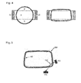
- FIG. 3 shows the realization variant described above additionally in a side, top and front view.
- the front view illustrates the substantially rectangular cross section of the breathing tube. It can also be seen that the side walls are designed by their bevel so that the breathing tube can not be rotated by 180 ° inserted into the measuring system.
- the breathing tube of the present invention in the exemplary embodiment illustrated here has an almost rectangular cross-section. This shape has a better "penetration" of the cross section through the ultrasonic beam compared to a round or slightly oval cross-sectional shape.
- FIG. 4 Two variants of a breathing tube are shown together with the laterally arranged ultrasonic cells.
- the ultrasonic cells are designated 10 and 20, respectively. Both are both transmitters and receivers of UI-traschallsignalen.
- the area between the two interrupted lines A between the ultrasound cells represents the area of the volume flow covered by the ultrasound beam. This means that in this area the volume flow in the respiratory tube can be measured by the ultrasound beam.
- the total volume flow in the outer region B is not detected by the ultrasound. If the volume flow over the cross section of the breathing tube is distributed unevenly, this effect leads to errors in the measurement result.
- the ratio of the areas A to B is better, ie a larger percentage of the volume flow is actually detected by the ultrasonic measurement signal. This is so in the right embodiment in FIG. 4 , Which substantially corresponds to the shape of the present inventive embodiment, lead to a reduction of the error in uneven distribution of the volume flow in the breathing tube.
- the position of the breathing tube can be detected, since the indicators are arranged along the longitudinal axis. For recognizing the type of respiratory tube, this is coded into the structure of the comb-like indicator. Elevations and depressions in the mechanical structure of the indicator produce characteristic light / shadow sequences on the line sensor. From this image of the indicator on the line sensor, an identification number can be calculated in the control of the ultrasonic flow measuring system.
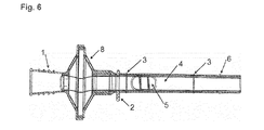
- FIG. 6 shows a longitudinal section through an alternative embodiment of the breathing tube according to the invention.
- this breathing tube corresponds to that according to FIG. 2 , However, here is different from the one in FIG. 2 illustrated embodiment, the mouthpiece 1 and an additional filter insert 8 attachable connected to the rest of the body 4 of the breathing tube.
- the connector provided here allows easy replacement of mouthpiece 1 and / or filter cartridge. 8
Abstract
Die Erfindung betrifft ein Atemrohr zum Einsatz in Ultraschall-Durchflussmesssystemen zur Bestimmung des Volumenstromes und/oder der Molmasse der Atmung von Menschen und Tieren. Erfindungsgemäß weist das Atemrohr zumindest bereichsweise einen mehreckigen Querschnitt auf. Des Weiteren ist am Atemrohr mindestens ein Indikator ausgebildet, der über ein externes optisches Mittel auslesbar ist.The invention relates to a breathing tube for use in ultrasonic flow measuring systems for determining the volume flow and / or the molecular weight of the respiration of humans and animals. According to the invention, the respiratory tube at least partially has a polygonal cross-section. Furthermore, at least one indicator is formed on the breathing tube, which can be read out via an external optical means.
Description
Die Erfindung betrifft ein Atemrohr zum Einsatz in Ultraschall-Durchflussmesssystemen zur Bestimmung des Volumenstromes und/oder der Molmasse der Atmung von Menschen und Tieren.The invention relates to a breathing tube for use in ultrasonic flow measuring systems for determining the volume flow and / or the molecular weight of the respiration of humans and animals.
Zur Messung der Atemströmung wird in der Regel eines der folgenden Messverfahren eingesetzt:
- 1. Verfahren, welche auf der Messung des durch die Strömung bedingten Druckabfalls über einen Widerstand im Atemrohr beruhen;
- 2. Verfahren, welche die Geschwindigkeit der Gase mittels Abkühlung eines geheizten Drahtes in der Strömung bestimmen;
- 3. Verfahren, welche auf der Messung der Rotationsgeschwindigkeit von Turbinen basieren und
- 4. Verfahren, welche die Laufzeiten von Ultraschallimpulsen messen, die mit und entgegen der Strömung laufen.
- A method based on measuring the pressure drop due to flow through a resistance in the breathing tube;
- 2. methods which determine the velocity of the gases by means of cooling a heated wire in the flow;
- 3. Methods based on the measurement of rotational speed of turbines and
- 4. Methods which measure the transit times of ultrasonic pulses traveling with and against the flow.
Das auf Ultraschall-Laufzeitmessung basierende Verfahren, das in der
- Es besteht ein sehr großer Messbereich mit hoher Ansprechgeschwindigkeit, d.h. sowohl sehr hohe Spitzenflüsse als auch sehr tiefe Flüsse müssen genau mit hoher Abtastrate gemessen werden.
- Es existieren stark wechselnde Gaszusammensetzungen. Bei gewissen medizinischen Testverfahren werden unterschiedliche Gase eingesetzt. Im Idealfall haben diese keinen Einfluss auf die Messung der Atemstromgeschwindigkeit.
- Es müssen gute Hygieneeigenschaften bestehen. Das bedeutet, dass das Gerät beim Wechsel der Patienten reinigbar sein muss, um eine Kreuzkontamination unter allen Umständen zu vermeiden.
- There is a very large measuring range with a high response speed, ie both very high peak flows and very deep flows have to be measured exactly with a high sampling rate.
- There are widely varying gas compositions. Certain medical tests use different gases. Ideally, these do not affect the measurement of the respiratory flow rate.
- There must be good hygiene properties. This means that the device must be cleanable when changing patients in order to avoid cross-contamination under all circumstances.
Bei Durchflussmessgeräten, welche auf Ultraschall-Laufzeitmessung basieren, werden zur Vermeidung von Kreuzkontamination häufig auswechselbare Atemrohre eingesetzt. In der
Diese bislang verwendeten Atemrohre weisen im Wesentlichen einen runden oder leicht ovalen Querschnitt auf. Oft wird ein Innendurchmesser von 20 mm bevorzugt, weil dieser einem verbreiteten Rohrdurchmesser in der Anästhesie entspricht. In der
- Ein
integriertes Mundstück 1, welches der Patient mit den Lippen umschließt, - einen
Ring 2, mit dreieckiger Positionsmarke, welche die Position des Atemrohres im Messsystem eindeutig festlegt, Dichtlippen 3, welche das Atemrohr gegenüber dem Messsystem abdichten,- einen
Körper 4 des Atemrohrs mit einem kreisrunden Innendurchmesser von ca. 20 mm, ovale Schallöffnungen 5, welche eine Ultraschallübertragung zwischen den beiden, schräg angeordneten, Sende- und Empfangselementen des hier nicht mehr dargestellten Ultraschall-Durchflussmesssystems erlaubt und- einen
Widerhaken 6, welcher verhindert, dass das Atemrohr unabsichtlich wieder aus dem Messsystem herausgeschoben werden kann.
- An integrated
mouthpiece 1, which the patient wraps around with his lips, - a
ring 2, with a triangular position mark, which clearly defines the position of the breathing tube in the measuring system, - Sealing
lips 3, which seal the breathing tube with respect to the measuring system, - a
body 4 of the breathing tube with a circular inner diameter of about 20 mm, -
oval sound openings 5, which allows an ultrasound transmission between the two, obliquely arranged, transmitting and receiving elements of the ultrasonic flow measuring system (not shown here) and - a
barb 6, which prevents the breathing tube can be unintentionally pushed out of the measuring system again.
Die Atemrohre werden üblicherweise in Spritzgusstechnik hergestellt. Die Öffnungen der Schallöffnungen sind üblicherweise mit Netzen versehen, welche beim Produktionsprozess in das Material eingespritzt werden. Diese Netze weisen eine sehr kleine offene Fläche auf, erlauben eine Übertragung von Schallimpulsen und verhindern andererseits einen Strömungsabriss und somit starke Turbulenzen im Atemrohr. Da pro Patient nur ein Atemrohr verwendet wird, verhindern diese Netze, dass es zu Kreuzkontamination zwischen Patienten kommen kann.The breathing tubes are usually manufactured by injection molding. The openings of the sound openings are usually provided with nets which are injected into the material during the production process. These nets have a very small open area, allow a transmission of sound pulses and prevent on the other hand a stall and thus strong turbulence in the breathing tube. Since only one breathing tube is used per patient, these meshes prevent cross-contamination between patients.
Die vorbeschriebenen austauschbaren Atemrohre weisen aber aufgrund ihrer Konstruktionsweise einige Nachteile auf, die im Folgenden wiedergegeben sind:
- Der Ring mit der dreieckigen Positionsmarke garantiert nicht, dass das Atemrohr vom Benutzer immer in der exakt gleichen Position in das Messsystem eingeschoben wird.
- Das Atemrohr kann beispielsweise nicht vollständig eingeschoben oder auch nicht exakt ausgerichtet sein (unerwünschte Rotation des Atemrohrs). Ein nicht korrekt im Messsystem positioniertes Atemrohr führt aber zu Messfehlern in der Geschwindigkeitsmessung.
- Die Ultraschall-Durchstrahlung der Messstrecke in einem runden Querschnitt ist nicht optimal und erfasst die oberen bzw. unteren Anteile des Luftstromes nicht. Bei ungleicher Verteilung des Luftstromes über den Querschnitt kann dies ebenfalls zu Messfehlern führen.
- The ring with the triangular position mark does not guarantee that the user will always insert the breathing tube in exactly the same position into the measuring system.
- The breathing tube, for example, can not be completely inserted or not aligned exactly (unwanted rotation of the breathing tube). However, a breathing tube not correctly positioned in the measuring system leads to measurement errors in the speed measurement.
- The ultrasonic radiation of the measuring section in a round cross-section is not optimal and does not detect the upper or lower portions of the air flow. If the air flow is distributed unevenly across the cross section, this can also lead to measurement errors.
Aufgabe der Erfindung ist es, ein gattungsgemäßes Atemrohr derart weiter zu bilden, dass die vorgenannten Nachteile behoben werden. Insbesondere soll im System erkannt werden, ob ein Atemrohr in seiner korrekten Position eingesetzt ist.The object of the invention is to further develop a generic breathing tube so that the aforementioned disadvantages are eliminated. In particular, it should be recognized in the system whether a breathing tube is inserted in its correct position.
Erfindungsgemäß wird diese Aufgabe durch die Kombination der Merkmale des Anspruchs 1 gelöst. Beim gattungsgemäßen Atemrohr zum Einsatz in Ultraschall-Durchflussmesssystemen zur Bestimmung des Volumenstroms und /oder der Molmasse der Atmung von Menschen und Tieren wird demzufolge das Atemrohr zumindest bereichsweise mit einem mehreckigen Querschnitt ausgeführt. Dabei weist das Atemrohr mindestens einen Indikator auf, der über ein externes optisches Mittel auslesbar ist.According to the invention this object is achieved by the combination of the features of
Der zumindest bereichsweise vorgesehene mehreckige Querschnitt des Atemrohrs verhindert, dass das Atemrohr verdreht in das Messsystem eingesetzt werden kann. Vorzugsweise ist der mehreckige Querschnitt hierzu asymmetrisch ausgeführt, um ein falsches Einsetzen des Atemrohres (beispielsweise durch versehentliches Verdrehen um einen bestimmten Winkelbetrag) zu verhindern.The at least partially provided polygonal cross section of the breathing tube prevents the breathing tube can be twisted inserted into the measuring system. Preferably, the polygonal cross-section for this purpose is designed asymmetrically, in order to prevent incorrect insertion of the breathing tube (for example, by accidental rotation by a certain angle).
Über den mindestens einen Indikator kann automatisch das Vorhandensein des Atemrohrs im Messsystem festgestellt werden. Darüber hinaus kann auch die korrekte Positionierung in Längsachse des Atemrohrs innerhalb des Messsystems sichergestellt werden. Über die Auswahl des Indikators kann zusätzlich eine Information zum Typ des Atemrohrs ausgelesen werden.The at least one indicator can automatically detect the presence of the breathing tube in the measuring system. In addition, the correct positioning in the longitudinal axis of the breathing tube can be ensured within the measuring system. By selecting the indicator, information about the type of breathing tube can also be read out.
Vorteilhafte Ausgestaltungen der Erfindung ergeben sich aus den sich an den Hauptanspruch anschließenden Unteransprüchen.Advantageous embodiments of the invention will become apparent from the subsequent claims to the main claim.
Demnach kann der mindestens eine Indikator durch Flächen auf der äußeren Oberfläche des Atemrohres gebildet sein, die sich durch die Farbe und/oder den Reflexionsgrad von der übrigen Oberfläche des Atemrohres unterscheiden. Durch diese Ausbildung des mindestens einen Indikators, kann dieser über ein optisches Mittel, wie beispielsweise eine Lichtschranke oder eine Reflexionslichtschranke ausgelesen werden. Diese Lichtschranken sind in dem entsprechenden Ultraschall-Durchflussmesssystem integriert, in welchem das Atemrohr eingesetzt wird.Accordingly, the at least one indicator may be formed by areas on the outer surface of the breathing tube, which differ by the color and / or the degree of reflection from the remaining surface of the breathing tube. As a result of this design of the at least one indicator, it can be detected by an optical means, such as a light barrier or a reflection light barrier can be read. These light barriers are integrated in the corresponding ultrasonic flow measuring system, in which the breathing tube is used.
Gemäß einer besonders vorteilhaften Ausgestaltung der Erfindung kann der mindestens eine Indikator durch die Formgebung der äußeren Oberfläche des Atemrohrs gebildet sein. Dabei kann beispielsweise das Atemrohr zur Bildung des mindestens einen Indikators im Bereich mindestens einer Kante kammartig geformt sein. Durch die hierdurch gebildeten Zwischenräume in der kammartig geformten Kantenoberfläche können beispielsweise Lichtstrahlen auf die optischen Sensoren hindurchtreten.According to a particularly advantageous embodiment of the invention, the at least one indicator may be formed by the shape of the outer surface of the breathing tube. In this case, for example, the breathing tube to form the at least one indicator in the region of at least one edge may be formed like a comb. As a result of the intermediate spaces formed in the comb-like shaped edge surface, for example, light beams can pass onto the optical sensors.
Gemäß einer weiteren vorteilhaften Ausgestaltung der Erfindung weist das Atemrohr einen nahezu rechteckigen Querschnitt auf, wobei die Außenseiten des Atemrohrs leicht angeschrägt verlaufen. Hiermit kann verhindert werden, dass das Atemrohr versehentlich um 180 ° versetzt in das Messsystem eingesetzt wird.According to a further advantageous embodiment of the invention, the breathing tube has a nearly rectangular cross section, wherein the outer sides of the breathing tube are slightly bevelled. This can be used to prevent the breathing tube from being accidentally inserted into the measuring system by 180 °.
Vorteilhaft weist das Atemrohr auf seiner Oberfläche mindestens eine umlaufende Dichtlippe auf. Dabei kann die mindestens eine Dichtlippe im Zusammenwirken mit der Messvorrichtung, in welche das Atemrohr einsetzbar ist, aufgrund resultierender gleichmäßiger nach außen wirkender Kraft eine sichere Abdichtung mit der Innenfläche der Messvorrichtung, d.h. des Ultraschall-Durchflussmesssystems, bewirken.Advantageously, the breathing tube has on its surface at least one circumferential sealing lip. In this case, the at least one sealing lip in cooperation with the measuring device, in which the breathing tube can be inserted, due to the resulting uniform outward force, a secure seal with the inner surface of the measuring device, i. of the ultrasonic flow measuring system cause.
Die Öffnungen im Atemrohr, die zur Durchleitung der Utlraschallimpulse dienen, sind vorteilhaft über ein gewebeartiges Netz verschlossen. Das gewebeartige Netz kann dabei jeweils beim Spritzvorgang zur Erzeugung des aus einem spritzbaren Kunststoff bestehenden Atemrohrs aus dem gleichen Material mitspritzbar sein. Alternativ kann das gewebeartige Netz aber auch aus einem zu dem Atemrohr unterschiedlichen Material bestehen und in einem gesonderten Arbeitsschritt zur Abdeckung der Öffnung mit dem Atemrohr verbindbar sein.The openings in the breathing tube, which serve to transmit the Utlraschallimpulse, are advantageously closed by a fabric-like network. The fabric-like mesh can be sprayed in each case during the injection process to produce the existing of a sprayable plastic breathing tube made of the same material. Alternatively, however, the fabric-like mesh can also consist of a material that is different from the respiratory tube and can be connected to the respiratory tube in a separate working step to cover the opening.
Gemäß einer weiteren vorteilhaften Ausgestaltung der Erfindung kann das Atemrohr ein separat aufsteckbares Mundstück aufweisen.
Des Weiteren kann das Atemrohr zusätzlich einen Filter aufweisen, der vorzugsweise auch aufsteckbar gestaltet werden kann.According to a further advantageous embodiment of the invention, the breathing tube may have a separately attachable mouthpiece.
Furthermore, the breathing tube can additionally have a filter, which can preferably also be designed pluggable.
Schließlich kann das Atemrohr auch auf der äußeren Oberfläche mindestens einen Vorsprung aufweisen, über den das Atemrohr aus dem Utlraschall-Durchflussmesssystem ausschiebbar ist.Finally, the breathing tube can also have on the outer surface at least one projection over which the breathing tube can be pushed out of the Utlraschall flow measuring system.
Vorteilhaft können auch unterschiedliche Typen des Atemrohres unterschiedliche innere Querschnitte aufweisen, um damit auf spezielle Anwendung bezüglich des Volumens des Atemrohres und der Messauflösung optimiert zu werden.Advantageously, different types of the breathing tube may also have different internal cross sections in order to be optimized for specific applications with regard to the volume of the breathing tube and the measurement resolution.
Eine zuverlässige Erkennung des Typs des Atemrohrs über den wenigstens einen Indikator ermöglicht zusätzlich vorteilhaft eine Anpassung der Messauswertung des Ultraschall-Durchflussmesssystems. Hier kann die Linearisierung des gemessenen Flusssignals, d.h. der mathematische Zusammenhang zwischen dem gemessenen Transitzeiten und der ausgegebenen Geschwindigkeit des Volumenstroms, auf das jeweils eingesetzte Atemrohr abgestimmt werden.A reliable detection of the type of breathing tube via the at least one indicator additionally advantageously allows an adaptation of the measurement evaluation of the ultrasonic flow measuring system. Here, the linearization of the measured flux signal, i. the mathematical relationship between the measured transit times and the output velocity of the volume flow to be matched to the respective breathing tube.
Weitere Merkmale, Einzelheiten und Vorteile der Erfindung werden anhand von in der Zeichnung dargestellten Ausführungsbeispielen näher erläutert.Further features, details and advantages of the invention will be explained in more detail with reference to embodiments shown in the drawing.
Es zeigen:
- Figur 1:
- Eine schematische Darstellung eines Atemrohrs nach dem Stand der Technik;
- Figur 2:
- Eine perspektivische Ansicht einer ersten Ausführungsform des erfindungsgemäßen Atemrohrs;
- Figur 3:
- Das
Atemrohr gemäß Figur 2 in Seiten-, Drauf- und Frontsicht; - Figur 4:
- Eine schematische Darstellung zur Verdeutlichung der Durchstrahlung der Messstrecke bei einem runden und rechteckigen Atemrohr;
- Figur 5:
- Einen Querschnitt durch das
Atemrohr gemäß Figur 2 und - Figur 6:
- Einen Längsschnitt durch ein Atemrohr gemäß einer zweiten Ausführungsform der Erfindung.
- FIG. 1:
- A schematic representation of a breathing tube according to the prior art;
- FIG. 2:
- A perspective view of a first embodiment of the breathing tube according to the invention;
- FIG. 3:
- The breathing tube according to
FIG. 2 in side, top and front view; - FIG. 4:
- A schematic representation to illustrate the irradiation of the measuring section with a round and rectangular breathing tube;
- FIG. 5:
- A cross section through the breathing tube according to
FIG. 2 and - FIG. 6:
- A longitudinal section through a breathing tube according to a second embodiment of the invention.
Eine Ausführungsform des erfindungsgemäßen Atemrohrs ist in
Das Atemrohr weist zwei umlaufende Dichtlippen 3 in seinem vorderen und hinteren Bereich auf, welche zur Abdichtung gegenüber dem hier nicht dargestellten Ultraschall-Messsystem dienen. Der eigentliche Körper 4 des Atemrohres hat einen annähernd rechteckigen Querschnitt, wobei die Seitenwandungen allerdings leicht angeschrägt sind. Somit ergibt sich genau genommen eine Trapezform mit abgerundeten Ecken. Die beiden vorgesehenen Öffnungen auf den gegenüberliegenden Seiten des Atemrohres, die zur Übertragung des Ultraschalls dienen, sind jeweils mit Netzen verschlossen. Schließlich ist ein Widerhaken 6 am Atemrohr angespritzt, welcher verhindert, dass das Atemrohr unabsichtlich wieder aus dem Mess-system herausgeschoben werden kann.The breathing tube has two
Im oberen und unteren Randbereich des Atemrohrs sind auf der äußeren Oberfläche jeweils in der Kante zwei mechanische Indikatoren in Form einer angespritzten kammartigen Struktur vorgesehen. Die
Gegenüber den bisher üblichen Atemrohren zur Verwendung in Ultraschall-Durchflussmesssystemen weist das Atemrohr der vorliegenden Erfindung in dem hier dargestellten Ausführungsbeispiel einen nahezu rechteckigen Querschnitt auf. Diese Form weist gegenüber einer runden oder leicht ovalen Querschnittsform eine bessere "Durchdringung" des Querschnitts durch den Ultraschallstrahl auf.Compared with the hitherto customary breathing tubes for use in ultrasonic flow measuring systems, the breathing tube of the present invention in the exemplary embodiment illustrated here has an almost rectangular cross-section. This shape has a better "penetration" of the cross section through the ultrasonic beam compared to a round or slightly oval cross-sectional shape.
In der
Die
- a) das Vorhandensein eines Atemrohrs,
- b) die Postitionen des Atemrohrs innerhalb des Messsystems sowie
- c) der Typ des Atemrohrs.
- a) the presence of a breathing tube,
- b) the positions of the breathing tube within the measuring system as well as
- c) the type of breathing tube.
Die Position des Atemrohrs kann erfasst werden, da die Indikatoren entlang der Längsachse angeordnet sind. Zur Erkennung des Atemrohrtyps, wird dieser in die Struktur des kammartigen Indikators kodiert. Erhöhungen und Vertiefungen in der mechanischen Struktur des Indikators erzeugen charakteristische Licht-/Schattenabfolgen auf dem Zeilensensors. Aus diesem Abbild des Indikators auf dem Zeilensensors kann in der Steuerung des Ultraschall-Durchflussmesssystems eine Indentifikationsnummer berechnet werden.The position of the breathing tube can be detected, since the indicators are arranged along the longitudinal axis. For recognizing the type of respiratory tube, this is coded into the structure of the comb-like indicator. Elevations and depressions in the mechanical structure of the indicator produce characteristic light / shadow sequences on the line sensor. From this image of the indicator on the line sensor, an identification number can be calculated in the control of the ultrasonic flow measuring system.
Die
Claims (13)
dadurch gekennzeichnet,
dass das Atemrohr zumindest bereichsweise einen mehreckigen Querschnitt aufweist und dass am Atemrohr mindestens ein Indikator ausgebildet ist, der über ein externes optisches Mittel auslesbar ist.Breathing tube for use in ultrasonic flow measuring systems for the determination of the volume flow and / or the molecular mass of the respiration of humans and animals,
characterized,
that the breathing tube at least in regions has a polygonal cross-section and that the breathing tube at least one indicator is formed which is read out via an external optical means.
Priority Applications (1)
| Application Number | Priority Date | Filing Date | Title |
|---|---|---|---|
| PL14198887T PL3017760T3 (en) | 2014-11-10 | 2014-12-18 | Breathing tube for use in ultrasound flow meter systems |
Applications Claiming Priority (1)
| Application Number | Priority Date | Filing Date | Title |
|---|---|---|---|
| DE102014016608.2A DE102014016608B3 (en) | 2014-11-10 | 2014-11-10 | Breathing tube for use in ultrasonic flow measuring systems |
Publications (2)
| Publication Number | Publication Date |
|---|---|
| EP3017760A1 true EP3017760A1 (en) | 2016-05-11 |
| EP3017760B1 EP3017760B1 (en) | 2019-06-19 |
Family
ID=52338869
Family Applications (1)
| Application Number | Title | Priority Date | Filing Date |
|---|---|---|---|
| EP14198887.3A Active EP3017760B1 (en) | 2014-11-10 | 2014-12-18 | Breathing tube for use in ultrasound flow meter systems |
Country Status (8)
| Country | Link |
|---|---|
| US (1) | US10786178B2 (en) |
| EP (1) | EP3017760B1 (en) |
| JP (1) | JP6029699B2 (en) |
| CN (1) | CN105581796B (en) |
| DE (1) | DE102014016608B3 (en) |
| ES (1) | ES2745463T3 (en) |
| HU (1) | HUE045767T2 (en) |
| PL (1) | PL3017760T3 (en) |
Cited By (3)
| Publication number | Priority date | Publication date | Assignee | Title |
|---|---|---|---|---|
| EP3403578A1 (en) | 2017-05-16 | 2018-11-21 | ndd Medizintechnik AG | Holding device for a breathing tube and method for reading out a coding on a surface of a breathing tube |
| EP3566647A1 (en) | 2018-05-07 | 2019-11-13 | ndd Medizintechnik AG | Method for verifying a calibration of a spirometer |
| EP4124292A1 (en) | 2021-07-29 | 2023-02-01 | ndd Medizintechnik AG | Breathing tube arrangement for a lung function diagnostics device comprising a distal filter element |
Families Citing this family (8)
| Publication number | Priority date | Publication date | Assignee | Title |
|---|---|---|---|---|
| HUE050158T2 (en) | 2017-05-16 | 2020-11-30 | Ndd Medizintechnik Ag | Method for conditioning a breathing tube |
| US20180333076A1 (en) | 2017-05-17 | 2018-11-22 | Ndd Medizintechnik Ag | Breathing tube for use in lung function diagnostics |
| USD918378S1 (en) * | 2018-06-19 | 2021-05-04 | SDI Diagnostics Inc. | Breathing tube with in-line filter for lung diagnostics |
| USD903095S1 (en) * | 2018-06-19 | 2020-11-24 | SDI Diagnostics Inc. | Breathing tube with in-line filter for lung diagnostics |
| USD965788S1 (en) * | 2020-07-29 | 2022-10-04 | Ndd Medizintechnik Ag | Tube for a breath analysis device |
| US20230022892A1 (en) * | 2021-07-14 | 2023-01-26 | Sdi Diagnostics, Inc. | Breathing tube for use with spirometers that employ ultrasonic measurement systems |
| CN113558659B (en) * | 2021-07-30 | 2023-07-04 | 重庆安酷科技有限公司 | High-precision ultrasonic lung function detector and detection method thereof |
| US20230191306A1 (en) * | 2021-12-22 | 2023-06-22 | Sdi Diagnostics, Inc. | Breathing tube filter and filter assembly |
Citations (7)
| Publication number | Priority date | Publication date | Assignee | Title |
|---|---|---|---|---|
| DE3941546A1 (en) * | 1989-12-15 | 1991-06-20 | Siemens Ag | ULTRASONIC GAS / LIQUID FLOW METER |
| EP0597060A1 (en) | 1992-06-03 | 1994-05-18 | Reutter Georg | Spirometer, in particular ultrasound spirometer. |
| US5647370A (en) | 1994-07-01 | 1997-07-15 | Ndd Medizintechnik Gmbh | Ultrasonic spirometer |
| DE19605652A1 (en) * | 1996-02-15 | 1997-08-21 | Siemens Ag | Ultrasound flowmeter calibration method |
| US6612306B1 (en) * | 1999-10-13 | 2003-09-02 | Healthetech, Inc. | Respiratory nitric oxide meter |
| JP2008107234A (en) * | 2006-10-26 | 2008-05-08 | Matsushita Electric Ind Co Ltd | Ultrasonic fluid measuring apparatus |
| DE102009036288A1 (en) * | 2009-08-06 | 2011-02-10 | Aceos Gmbh | Device for taking a gas sample from human respiration |
Family Cites Families (20)
| Publication number | Priority date | Publication date | Assignee | Title |
|---|---|---|---|---|
| US5234117A (en) * | 1991-12-10 | 1993-08-10 | Garvin Dawn R | Straw adaptor for baby bottle |
| WO1997048338A1 (en) * | 1996-06-21 | 1997-12-24 | Desert Moon Development Limited Partnership | Resistive element and calibrated air tube for spirometer |
| US5715831A (en) | 1996-06-21 | 1998-02-10 | Desert Moon Development Limited Partnership | Calibrated air tube for spirometer |
| US5789660A (en) * | 1996-07-15 | 1998-08-04 | Novametrix Medical Systems, Inc. | Multiple function airway adapter |
| US6126610A (en) * | 1997-11-03 | 2000-10-03 | Novametrix Medical Systems, Inc. | Pneumatic connector with encoding |
| JP2002501806A (en) * | 1998-02-05 | 2002-01-22 | ジェームズ アール モールト | Metabolic calorimeter using respiratory gas analysis |
| DE19910620C2 (en) | 1999-03-10 | 2001-02-01 | Siemens Ag | Device for performing arithmetic operations |
| WO2000055581A1 (en) * | 1999-03-17 | 2000-09-21 | Matsushita Electric Industrial Co., Ltd. | Ultrasonic flowmeter |
| US6427694B1 (en) * | 2000-11-22 | 2002-08-06 | Mpv-Truma Gesellschaft Fur Medizintechnische Produkte Gmbh | Nasal breathing mask |
| US7018363B2 (en) * | 2001-01-18 | 2006-03-28 | Medrad, Inc. | Encoding and sensing of syringe information |
| KR100462455B1 (en) * | 2002-05-07 | 2004-12-17 | 이규상 | A drinking straw with valve function |
| EP1632178A1 (en) * | 2004-09-03 | 2006-03-08 | ndd Medizintechnik AG | Method for non-cooperative lung function diagnosis using ultrasound |
| EP1821076A1 (en) * | 2004-12-09 | 2007-08-22 | Konica Minolta Medical & Graphic, Inc. | Flow rate measurement device |
| US7785514B2 (en) * | 2006-05-18 | 2010-08-31 | Mccarthy Peter T | Snorkels, flexible tubes, mouthpieces and methods |
| WO2007146133A2 (en) * | 2006-06-07 | 2007-12-21 | Ventus Medical, Inc. | Layered nasal devices |
| US8109268B2 (en) | 2007-01-08 | 2012-02-07 | Dräger Medical GmbH | Device for detecting a gas volume flow |
| CN101059338B (en) | 2007-05-16 | 2010-08-25 | 赵跃 | Laser image measurement based coal coke oven carbonization chamber position detection method |
| US10918308B2 (en) * | 2007-05-18 | 2021-02-16 | Koninklijke Philips N.V. | Respiratory component measurement system including a sensor for detecting orientation or motion |
| JP2013250254A (en) * | 2012-06-01 | 2013-12-12 | Chest M I Inc | Multiple reflection prevention rectifier tube for ultrasonic spirometer |
| KR101425662B1 (en) * | 2013-03-05 | 2014-08-05 | 주식회사 세라젬메디시스 | Biosensor having identification information |
-
2014
- 2014-11-10 DE DE102014016608.2A patent/DE102014016608B3/en active Active
- 2014-12-18 ES ES14198887T patent/ES2745463T3/en active Active
- 2014-12-18 HU HUE14198887A patent/HUE045767T2/en unknown
- 2014-12-18 EP EP14198887.3A patent/EP3017760B1/en active Active
- 2014-12-18 PL PL14198887T patent/PL3017760T3/en unknown
-
2015
- 2015-03-02 JP JP2015040069A patent/JP6029699B2/en active Active
- 2015-07-24 US US14/809,029 patent/US10786178B2/en active Active
- 2015-07-27 CN CN201510447957.5A patent/CN105581796B/en active Active
Patent Citations (9)
| Publication number | Priority date | Publication date | Assignee | Title |
|---|---|---|---|---|
| DE3941546A1 (en) * | 1989-12-15 | 1991-06-20 | Siemens Ag | ULTRASONIC GAS / LIQUID FLOW METER |
| EP0597060A1 (en) | 1992-06-03 | 1994-05-18 | Reutter Georg | Spirometer, in particular ultrasound spirometer. |
| US5419326A (en) | 1992-06-03 | 1995-05-30 | Ndd Medizintechnik Gmbh | Spirometer, more particularly an ultrasonic spirometer |
| EP0597060B1 (en) | 1992-06-03 | 1997-04-16 | NDD Medizintechnik GmbH | Spirometer, in particular ultrasound spirometer |
| US5647370A (en) | 1994-07-01 | 1997-07-15 | Ndd Medizintechnik Gmbh | Ultrasonic spirometer |
| DE19605652A1 (en) * | 1996-02-15 | 1997-08-21 | Siemens Ag | Ultrasound flowmeter calibration method |
| US6612306B1 (en) * | 1999-10-13 | 2003-09-02 | Healthetech, Inc. | Respiratory nitric oxide meter |
| JP2008107234A (en) * | 2006-10-26 | 2008-05-08 | Matsushita Electric Ind Co Ltd | Ultrasonic fluid measuring apparatus |
| DE102009036288A1 (en) * | 2009-08-06 | 2011-02-10 | Aceos Gmbh | Device for taking a gas sample from human respiration |
Cited By (5)
| Publication number | Priority date | Publication date | Assignee | Title |
|---|---|---|---|---|
| EP3403578A1 (en) | 2017-05-16 | 2018-11-21 | ndd Medizintechnik AG | Holding device for a breathing tube and method for reading out a coding on a surface of a breathing tube |
| US11154219B2 (en) | 2017-05-16 | 2021-10-26 | Ndd Medizintechnik Ag | Holding device for a breathing tube and method for reading out a coding on a surface of a breathing tube |
| EP3566647A1 (en) | 2018-05-07 | 2019-11-13 | ndd Medizintechnik AG | Method for verifying a calibration of a spirometer |
| US11162833B2 (en) | 2018-05-07 | 2021-11-02 | Ndd Medizintechnik Ag | Method for verifying a calibration of a spirometer |
| EP4124292A1 (en) | 2021-07-29 | 2023-02-01 | ndd Medizintechnik AG | Breathing tube arrangement for a lung function diagnostics device comprising a distal filter element |
Also Published As
| Publication number | Publication date |
|---|---|
| US10786178B2 (en) | 2020-09-29 |
| CN105581796A (en) | 2016-05-18 |
| ES2745463T3 (en) | 2020-03-02 |
| CN105581796B (en) | 2021-08-17 |
| US20160128608A1 (en) | 2016-05-12 |
| EP3017760B1 (en) | 2019-06-19 |
| DE102014016608B3 (en) | 2016-04-07 |
| JP2016087412A (en) | 2016-05-23 |
| JP6029699B2 (en) | 2016-11-24 |
| HUE045767T2 (en) | 2020-01-28 |
| PL3017760T3 (en) | 2019-12-31 |
Similar Documents
| Publication | Publication Date | Title |
|---|---|---|
| EP3017760B1 (en) | Breathing tube for use in ultrasound flow meter systems | |
| DE10035054C1 (en) | Medical respiration flow sensor has air resistance body in front of measuring sensor for respiration gas volumetric flow in common flow channel | |
| DE4222286C1 (en) | Ultrasound spirometer | |
| EP2568263B1 (en) | Portable ultrasound flow measurement system | |
| EP3639023A1 (en) | Breath alcohol measurement with contactless sample provision | |
| EP3404372A1 (en) | Ultrasound flow meter | |
| EP3388794B2 (en) | Measuring device for measuring a flow speed of a fluid | |
| DE10258997A1 (en) | Clamp-on ultrasonic flow meter for measuring mass flow rates in pipes or conduits, uses evaluation and control unit to optimize transducer positions based on comparison of a measurement value with a reference value | |
| DE102010053261B4 (en) | Measuring capsule for flow measurement | |
| DE102004017403B4 (en) | Measuring device for measuring the volume flow of a gas whose flow direction can reverse | |
| DE102008060922A1 (en) | Lung diagnostic device with two ultrasonic measuring sections | |
| DE102007024479A1 (en) | Method for determination of characteristics for dimensioning or interpretation of toothed bridge, involves affecting specific patient, where expected bridge force is determined, and is made available as dimensioning size | |
| DE102017202896A1 (en) | Flow measuring device and transmitter for process instrumentation with such a flow measuring device | |
| DE102016125745B4 (en) | Ultrasonic flow meter and method for measuring flow | |
| DE102008063503A1 (en) | Lung diagnostic device with four ultrasonic elements | |
| DE102019001995B3 (en) | Container for storing, mixing and / or cultivating a medium | |
| DE102007060046A1 (en) | Sensor arrangement for determining parameter of liquid medium flowing with main flow direction, particularly intake air mass of internal combustion engine, has sensor for determining parameter of liquid medium | |
| DE60012926T2 (en) | ARRANGEMENT FOR MEASURING THE PROPERTY OF A LIQUID IN A TUBE | |
| DE20321641U1 (en) | Respiratory flow sensor | |
| EP3301410A1 (en) | Location of an event in a sensor signal | |
| DE102008054257B4 (en) | Method for determining the flow rate of a breathing gas | |
| EP1731883B1 (en) | Method for detecting a geometry change of an ultrasonic flow measuring channel | |
| EP3748309A1 (en) | Ultrasound flow measuring device, blocking device and use in a blocking device | |
| DE102009036288A1 (en) | Device for taking a gas sample from human respiration | |
| DE102004008184B4 (en) | Air flow sensor |
Legal Events
| Date | Code | Title | Description |
|---|---|---|---|
| PUAI | Public reference made under article 153(3) epc to a published international application that has entered the european phase |
Free format text: ORIGINAL CODE: 0009012 |
|
| AK | Designated contracting states |
Kind code of ref document: A1 Designated state(s): AL AT BE BG CH CY CZ DE DK EE ES FI FR GB GR HR HU IE IS IT LI LT LU LV MC MK MT NL NO PL PT RO RS SE SI SK SM TR |
|
| AX | Request for extension of the european patent |
Extension state: BA ME |
|
| STAA | Information on the status of an ep patent application or granted ep patent |
Free format text: STATUS: REQUEST FOR EXAMINATION WAS MADE |
|
| 17P | Request for examination filed |
Effective date: 20161103 |
|
| STAA | Information on the status of an ep patent application or granted ep patent |
Free format text: STATUS: EXAMINATION IS IN PROGRESS |
|
| 17Q | First examination report despatched |
Effective date: 20180919 |
|
| GRAP | Despatch of communication of intention to grant a patent |
Free format text: ORIGINAL CODE: EPIDOSNIGR1 |
|
| STAA | Information on the status of an ep patent application or granted ep patent |
Free format text: STATUS: GRANT OF PATENT IS INTENDED |
|
| INTG | Intention to grant announced |
Effective date: 20190226 |
|
| GRAS | Grant fee paid |
Free format text: ORIGINAL CODE: EPIDOSNIGR3 |
|
| GRAA | (expected) grant |
Free format text: ORIGINAL CODE: 0009210 |
|
| STAA | Information on the status of an ep patent application or granted ep patent |
Free format text: STATUS: THE PATENT HAS BEEN GRANTED |
|
| AK | Designated contracting states |
Kind code of ref document: B1 Designated state(s): AL AT BE BG CH CY CZ DE DK EE ES FI FR GB GR HR HU IE IS IT LI LT LU LV MC MK MT NL NO PL PT RO RS SE SI SK SM TR |
|
| REG | Reference to a national code |
Ref country code: GB Ref legal event code: FG4D Free format text: NOT ENGLISH |
|
| REG | Reference to a national code |
Ref country code: CH Ref legal event code: EP |
|
| REG | Reference to a national code |
Ref country code: IE Ref legal event code: FG4D Free format text: LANGUAGE OF EP DOCUMENT: GERMAN |
|
| REG | Reference to a national code |
Ref country code: DE Ref legal event code: R096 Ref document number: 502014011988 Country of ref document: DE |
|
| REG | Reference to a national code |
Ref country code: AT Ref legal event code: REF Ref document number: 1144456 Country of ref document: AT Kind code of ref document: T Effective date: 20190715 |
|
| REG | Reference to a national code |
Ref country code: NL Ref legal event code: FP |
|
| REG | Reference to a national code |
Ref country code: SE Ref legal event code: TRGR |
|
| PG25 | Lapsed in a contracting state [announced via postgrant information from national office to epo] |
Ref country code: AL Free format text: LAPSE BECAUSE OF FAILURE TO SUBMIT A TRANSLATION OF THE DESCRIPTION OR TO PAY THE FEE WITHIN THE PRESCRIBED TIME-LIMIT Effective date: 20190619 Ref country code: HR Free format text: LAPSE BECAUSE OF FAILURE TO SUBMIT A TRANSLATION OF THE DESCRIPTION OR TO PAY THE FEE WITHIN THE PRESCRIBED TIME-LIMIT Effective date: 20190619 Ref country code: NO Free format text: LAPSE BECAUSE OF FAILURE TO SUBMIT A TRANSLATION OF THE DESCRIPTION OR TO PAY THE FEE WITHIN THE PRESCRIBED TIME-LIMIT Effective date: 20190919 Ref country code: FI Free format text: LAPSE BECAUSE OF FAILURE TO SUBMIT A TRANSLATION OF THE DESCRIPTION OR TO PAY THE FEE WITHIN THE PRESCRIBED TIME-LIMIT Effective date: 20190619 Ref country code: LT Free format text: LAPSE BECAUSE OF FAILURE TO SUBMIT A TRANSLATION OF THE DESCRIPTION OR TO PAY THE FEE WITHIN THE PRESCRIBED TIME-LIMIT Effective date: 20190619 |
|
| REG | Reference to a national code |
Ref country code: CH Ref legal event code: NV Representative=s name: SCHMAUDER AND PARTNER AG PATENT- UND MARKENANW, CH |
|
| REG | Reference to a national code |
Ref country code: LT Ref legal event code: MG4D |
|
| PG25 | Lapsed in a contracting state [announced via postgrant information from national office to epo] |
Ref country code: RS Free format text: LAPSE BECAUSE OF FAILURE TO SUBMIT A TRANSLATION OF THE DESCRIPTION OR TO PAY THE FEE WITHIN THE PRESCRIBED TIME-LIMIT Effective date: 20190619 Ref country code: LV Free format text: LAPSE BECAUSE OF FAILURE TO SUBMIT A TRANSLATION OF THE DESCRIPTION OR TO PAY THE FEE WITHIN THE PRESCRIBED TIME-LIMIT Effective date: 20190619 Ref country code: GR Free format text: LAPSE BECAUSE OF FAILURE TO SUBMIT A TRANSLATION OF THE DESCRIPTION OR TO PAY THE FEE WITHIN THE PRESCRIBED TIME-LIMIT Effective date: 20190920 Ref country code: BG Free format text: LAPSE BECAUSE OF FAILURE TO SUBMIT A TRANSLATION OF THE DESCRIPTION OR TO PAY THE FEE WITHIN THE PRESCRIBED TIME-LIMIT Effective date: 20190919 |
|
| REG | Reference to a national code |
Ref country code: HU Ref legal event code: AG4A Ref document number: E045767 Country of ref document: HU |
|
| PG25 | Lapsed in a contracting state [announced via postgrant information from national office to epo] |
Ref country code: EE Free format text: LAPSE BECAUSE OF FAILURE TO SUBMIT A TRANSLATION OF THE DESCRIPTION OR TO PAY THE FEE WITHIN THE PRESCRIBED TIME-LIMIT Effective date: 20190619 Ref country code: PT Free format text: LAPSE BECAUSE OF FAILURE TO SUBMIT A TRANSLATION OF THE DESCRIPTION OR TO PAY THE FEE WITHIN THE PRESCRIBED TIME-LIMIT Effective date: 20191021 Ref country code: SK Free format text: LAPSE BECAUSE OF FAILURE TO SUBMIT A TRANSLATION OF THE DESCRIPTION OR TO PAY THE FEE WITHIN THE PRESCRIBED TIME-LIMIT Effective date: 20190619 Ref country code: RO Free format text: LAPSE BECAUSE OF FAILURE TO SUBMIT A TRANSLATION OF THE DESCRIPTION OR TO PAY THE FEE WITHIN THE PRESCRIBED TIME-LIMIT Effective date: 20190619 Ref country code: CZ Free format text: LAPSE BECAUSE OF FAILURE TO SUBMIT A TRANSLATION OF THE DESCRIPTION OR TO PAY THE FEE WITHIN THE PRESCRIBED TIME-LIMIT Effective date: 20190619 |
|
| PG25 | Lapsed in a contracting state [announced via postgrant information from national office to epo] |
Ref country code: SM Free format text: LAPSE BECAUSE OF FAILURE TO SUBMIT A TRANSLATION OF THE DESCRIPTION OR TO PAY THE FEE WITHIN THE PRESCRIBED TIME-LIMIT Effective date: 20190619 Ref country code: IS Free format text: LAPSE BECAUSE OF FAILURE TO SUBMIT A TRANSLATION OF THE DESCRIPTION OR TO PAY THE FEE WITHIN THE PRESCRIBED TIME-LIMIT Effective date: 20191019 |
|
| REG | Reference to a national code |
Ref country code: ES Ref legal event code: FG2A Ref document number: 2745463 Country of ref document: ES Kind code of ref document: T3 Effective date: 20200302 |
|
| PG25 | Lapsed in a contracting state [announced via postgrant information from national office to epo] |
Ref country code: DK Free format text: LAPSE BECAUSE OF FAILURE TO SUBMIT A TRANSLATION OF THE DESCRIPTION OR TO PAY THE FEE WITHIN THE PRESCRIBED TIME-LIMIT Effective date: 20190619 |
|
| PG25 | Lapsed in a contracting state [announced via postgrant information from national office to epo] |
Ref country code: IS Free format text: LAPSE BECAUSE OF FAILURE TO SUBMIT A TRANSLATION OF THE DESCRIPTION OR TO PAY THE FEE WITHIN THE PRESCRIBED TIME-LIMIT Effective date: 20200224 |
|
| REG | Reference to a national code |
Ref country code: DE Ref legal event code: R097 Ref document number: 502014011988 Country of ref document: DE |
|
| PLBE | No opposition filed within time limit |
Free format text: ORIGINAL CODE: 0009261 |
|
| STAA | Information on the status of an ep patent application or granted ep patent |
Free format text: STATUS: NO OPPOSITION FILED WITHIN TIME LIMIT |
|
| PG2D | Information on lapse in contracting state deleted |
Ref country code: IS |
|
| 26N | No opposition filed |
Effective date: 20200603 |
|
| PG25 | Lapsed in a contracting state [announced via postgrant information from national office to epo] |
Ref country code: SI Free format text: LAPSE BECAUSE OF FAILURE TO SUBMIT A TRANSLATION OF THE DESCRIPTION OR TO PAY THE FEE WITHIN THE PRESCRIBED TIME-LIMIT Effective date: 20190619 Ref country code: MC Free format text: LAPSE BECAUSE OF FAILURE TO SUBMIT A TRANSLATION OF THE DESCRIPTION OR TO PAY THE FEE WITHIN THE PRESCRIBED TIME-LIMIT Effective date: 20190619 |
|
| PG25 | Lapsed in a contracting state [announced via postgrant information from national office to epo] |
Ref country code: LU Free format text: LAPSE BECAUSE OF NON-PAYMENT OF DUE FEES Effective date: 20191218 Ref country code: IE Free format text: LAPSE BECAUSE OF NON-PAYMENT OF DUE FEES Effective date: 20191218 |
|
| REG | Reference to a national code |
Ref country code: AT Ref legal event code: MM01 Ref document number: 1144456 Country of ref document: AT Kind code of ref document: T Effective date: 20191218 |
|
| PG25 | Lapsed in a contracting state [announced via postgrant information from national office to epo] |
Ref country code: CY Free format text: LAPSE BECAUSE OF FAILURE TO SUBMIT A TRANSLATION OF THE DESCRIPTION OR TO PAY THE FEE WITHIN THE PRESCRIBED TIME-LIMIT Effective date: 20190619 Ref country code: AT Free format text: LAPSE BECAUSE OF NON-PAYMENT OF DUE FEES Effective date: 20191218 |
|
| PG25 | Lapsed in a contracting state [announced via postgrant information from national office to epo] |
Ref country code: MT Free format text: LAPSE BECAUSE OF FAILURE TO SUBMIT A TRANSLATION OF THE DESCRIPTION OR TO PAY THE FEE WITHIN THE PRESCRIBED TIME-LIMIT Effective date: 20190619 |
|
| PG25 | Lapsed in a contracting state [announced via postgrant information from national office to epo] |
Ref country code: MK Free format text: LAPSE BECAUSE OF FAILURE TO SUBMIT A TRANSLATION OF THE DESCRIPTION OR TO PAY THE FEE WITHIN THE PRESCRIBED TIME-LIMIT Effective date: 20190619 |
|
| PGFP | Annual fee paid to national office [announced via postgrant information from national office to epo] |
Ref country code: PL Payment date: 20221116 Year of fee payment: 9 Ref country code: BE Payment date: 20221220 Year of fee payment: 9 |
|
| PGFP | Annual fee paid to national office [announced via postgrant information from national office to epo] |
Ref country code: ES Payment date: 20230119 Year of fee payment: 9 Ref country code: CH Payment date: 20230103 Year of fee payment: 9 |
|
| PGFP | Annual fee paid to national office [announced via postgrant information from national office to epo] |
Ref country code: IT Payment date: 20221230 Year of fee payment: 9 |
|
| PGFP | Annual fee paid to national office [announced via postgrant information from national office to epo] |
Ref country code: GB Payment date: 20231220 Year of fee payment: 10 |
|
| PGFP | Annual fee paid to national office [announced via postgrant information from national office to epo] |
Ref country code: TR Payment date: 20231211 Year of fee payment: 10 Ref country code: SE Payment date: 20231219 Year of fee payment: 10 Ref country code: NL Payment date: 20231219 Year of fee payment: 10 Ref country code: HU Payment date: 20231211 Year of fee payment: 10 Ref country code: FR Payment date: 20231219 Year of fee payment: 10 Ref country code: DE Payment date: 20231127 Year of fee payment: 10 |
|
| PGFP | Annual fee paid to national office [announced via postgrant information from national office to epo] |
Ref country code: PL Payment date: 20231102 Year of fee payment: 10 Ref country code: BE Payment date: 20231218 Year of fee payment: 10 |
|
| PGFP | Annual fee paid to national office [announced via postgrant information from national office to epo] |
Ref country code: ES Payment date: 20240118 Year of fee payment: 10 |