EP3009089A1 - System for direct vertebral rotation - Google Patents
System for direct vertebral rotation Download PDFInfo
- Publication number
- EP3009089A1 EP3009089A1 EP15187397.3A EP15187397A EP3009089A1 EP 3009089 A1 EP3009089 A1 EP 3009089A1 EP 15187397 A EP15187397 A EP 15187397A EP 3009089 A1 EP3009089 A1 EP 3009089A1
- Authority
- EP
- European Patent Office
- Prior art keywords
- jaws
- jaw
- instrument
- levers
- closed position
- Prior art date
- Legal status (The legal status is an assumption and is not a legal conclusion. Google has not performed a legal analysis and makes no representation as to the accuracy of the status listed.)
- Granted
Links
Images


Classifications
-
- A—HUMAN NECESSITIES
- A61—MEDICAL OR VETERINARY SCIENCE; HYGIENE
- A61B—DIAGNOSIS; SURGERY; IDENTIFICATION
- A61B17/00—Surgical instruments, devices or methods, e.g. tourniquets
- A61B17/56—Surgical instruments or methods for treatment of bones or joints; Devices specially adapted therefor
- A61B17/58—Surgical instruments or methods for treatment of bones or joints; Devices specially adapted therefor for osteosynthesis, e.g. bone plates, screws, setting implements or the like
- A61B17/68—Internal fixation devices, including fasteners and spinal fixators, even if a part thereof projects from the skin
- A61B17/70—Spinal positioners or stabilisers ; Bone stabilisers comprising fluid filler in an implant
- A61B17/7074—Tools specially adapted for spinal fixation operations other than for bone removal or filler handling
- A61B17/7076—Tools specially adapted for spinal fixation operations other than for bone removal or filler handling for driving, positioning or assembling spinal clamps or bone anchors specially adapted for spinal fixation
- A61B17/7077—Tools specially adapted for spinal fixation operations other than for bone removal or filler handling for driving, positioning or assembling spinal clamps or bone anchors specially adapted for spinal fixation for moving bone anchors attached to vertebrae, thereby displacing the vertebrae
- A61B17/7079—Tools requiring anchors to be already mounted on an implanted longitudinal or transverse element, e.g. where said element guides the anchor motion
-
- A—HUMAN NECESSITIES
- A61—MEDICAL OR VETERINARY SCIENCE; HYGIENE
- A61B—DIAGNOSIS; SURGERY; IDENTIFICATION
- A61B17/00—Surgical instruments, devices or methods, e.g. tourniquets
- A61B17/56—Surgical instruments or methods for treatment of bones or joints; Devices specially adapted therefor
- A61B17/58—Surgical instruments or methods for treatment of bones or joints; Devices specially adapted therefor for osteosynthesis, e.g. bone plates, screws, setting implements or the like
- A61B17/68—Internal fixation devices, including fasteners and spinal fixators, even if a part thereof projects from the skin
- A61B17/70—Spinal positioners or stabilisers ; Bone stabilisers comprising fluid filler in an implant
- A61B17/7047—Clamps comprising opposed elements which grasp one vertebra between them
-
- A—HUMAN NECESSITIES
- A61—MEDICAL OR VETERINARY SCIENCE; HYGIENE
- A61B—DIAGNOSIS; SURGERY; IDENTIFICATION
- A61B17/00—Surgical instruments, devices or methods, e.g. tourniquets
- A61B17/56—Surgical instruments or methods for treatment of bones or joints; Devices specially adapted therefor
- A61B17/58—Surgical instruments or methods for treatment of bones or joints; Devices specially adapted therefor for osteosynthesis, e.g. bone plates, screws, setting implements or the like
- A61B17/68—Internal fixation devices, including fasteners and spinal fixators, even if a part thereof projects from the skin
- A61B17/70—Spinal positioners or stabilisers ; Bone stabilisers comprising fluid filler in an implant
- A61B17/7074—Tools specially adapted for spinal fixation operations other than for bone removal or filler handling
- A61B17/7076—Tools specially adapted for spinal fixation operations other than for bone removal or filler handling for driving, positioning or assembling spinal clamps or bone anchors specially adapted for spinal fixation
- A61B17/7077—Tools specially adapted for spinal fixation operations other than for bone removal or filler handling for driving, positioning or assembling spinal clamps or bone anchors specially adapted for spinal fixation for moving bone anchors attached to vertebrae, thereby displacing the vertebrae
- A61B17/708—Tools specially adapted for spinal fixation operations other than for bone removal or filler handling for driving, positioning or assembling spinal clamps or bone anchors specially adapted for spinal fixation for moving bone anchors attached to vertebrae, thereby displacing the vertebrae with tubular extensions coaxially mounted on the bone anchors
-
- A—HUMAN NECESSITIES
- A61—MEDICAL OR VETERINARY SCIENCE; HYGIENE
- A61B—DIAGNOSIS; SURGERY; IDENTIFICATION
- A61B17/00—Surgical instruments, devices or methods, e.g. tourniquets
- A61B17/56—Surgical instruments or methods for treatment of bones or joints; Devices specially adapted therefor
- A61B17/58—Surgical instruments or methods for treatment of bones or joints; Devices specially adapted therefor for osteosynthesis, e.g. bone plates, screws, setting implements or the like
- A61B17/68—Internal fixation devices, including fasteners and spinal fixators, even if a part thereof projects from the skin
- A61B17/70—Spinal positioners or stabilisers ; Bone stabilisers comprising fluid filler in an implant
- A61B17/7074—Tools specially adapted for spinal fixation operations other than for bone removal or filler handling
- A61B17/7091—Tools specially adapted for spinal fixation operations other than for bone removal or filler handling for applying, tightening or removing longitudinal element-to-bone anchor locking elements, e.g. caps, set screws, nuts or wedges
-
- A—HUMAN NECESSITIES
- A61—MEDICAL OR VETERINARY SCIENCE; HYGIENE
- A61B—DIAGNOSIS; SURGERY; IDENTIFICATION
- A61B17/00—Surgical instruments, devices or methods, e.g. tourniquets
- A61B17/56—Surgical instruments or methods for treatment of bones or joints; Devices specially adapted therefor
- A61B17/58—Surgical instruments or methods for treatment of bones or joints; Devices specially adapted therefor for osteosynthesis, e.g. bone plates, screws, setting implements or the like
- A61B17/68—Internal fixation devices, including fasteners and spinal fixators, even if a part thereof projects from the skin
- A61B17/84—Fasteners therefor or fasteners being internal fixation devices
- A61B17/86—Pins or screws or threaded wires; nuts therefor
Definitions
- the present invention relates generally to an alignment linkage such as a direct vertebral rotation instrument for creating, restraining and/or maintaining horizontal rotation of the vertebrae during posterior spinal fusion operations.
- the present invention also relates to a method for creating, restraining and/or maintaining horizontal rotation of the vertebrae during posterior spinal fusion operations.
- the surgeon seeks to achieve a three-dimensional correction of the spinal column shape by realigning and instrumenting the vertebrae in order to achieve an eventual fusion of the vertebral bodies in the desired alignment.
- the misalignment of the patient's vertebral bodies is readily apparent in the sagittal and coronal planes, either visually or by radiography. More difficult to see and correct is rotational misalignment of the vertebrae about the axis in the defined along the length of the spine.
- This rotation is often characterized in the scoliosis patient by projection of the ribs of the back creating a so-called rib hump on one side of the back caused by the rotation of the thoracic vertebrae and the attached ribs. While the axis of rotation actually changes along the length of the spine due to the spines natural curvature, for convenience of discussion the axis will be discussed as if it is a vertical line.
- Direct vertebral rotation is one method of horizontally rotating and re-aligning vertebral bodies.
- DVR Direct vertebral rotation
- screws are implanted in the pedicles of the vertebrae and then a horizontal torque is applied by a lever arm or extension tube mounted to the screw head.
- a horizontal torque is applied by a lever arm or extension tube mounted to the screw head.
- Tubular lever arms are then placed on the screws in line with the axis of the screw.
- a force is then applied to the lever arms to rotate the spinal vertebrae. This brings the vertebrae into the desired positions and in line with one another.
- the surgeon and the surgeon's assistants face the difficult task of manually rotating and aligning the various lever arms to eventually fasten the pedicle screw assemblies to rods and form a construct holding the vertebrae in the desired alignment.
- Polyaxial pedicle screw assemblies have, by way of example, a cage shaped to receive a bone screw, a rod and a blocker or set screw engaging screw threads.
- cages have two arms that extend away from the screw and define a slot through which the rod can pass transverse to the axis of the cage.
- tulip-shaped Such cages are referred to as tulip-shaped.
- the cage can move polyaxially about the head of the bone screw until the assembly is fixed in a position. Once the rod is in place, the blocker is threaded within or on the outside of the cage.
- the blocker engages, directly or indirectly, the rod which in turn engages the head of the bone screw seated in the cage or engages the cage itself. The blocker thus locks or immobilizes the assembly.
- a monoaxial pedicle screw assembly generally includes a bone screw with an integral cage or head to receive the rod and blocker or nut.
- the lever arms apply torque to the bone screw and the bone screw, in turn, applies the torque to the vertebrae.
- Either a polyaxial or monoaxial screw assembly may be used.
- the lever must fit tightly and grasp the screw head in order to apply the torque. If a polyaxial screw assembly is used, the head should be immobilized in the direction of axial rotation to allow the transmission of torque.
- a polyaxial screw also has a limited extent of free travel and can create torque on the vertebra once the range of movement of the head is exceeded.
- the present invention fills the need described above by providing a system and method for rotation of vertebral segments for posterior spinal fusion.
- the invention is directed to an instrument and associated method that aligns and holds the DVR lever arms relative to each other to achieve an initial axial alignment of a segment of vertebrae and allow the DVR rotation by rotating the instrument and lever arms together.
- Joining the lever arms or extension tubes with such a clamping instrument allows the surgeon to more uniformly and easily rotate the tubes together and to stepwise achieve a relative orientation of a segment of vertebrae.
- the segment of vertebra to be aligned can be aligned collectively relative to adjacent spinal segments.
- the invention teaches a method of direct vertebral rotation, wherein the steps include attaching pedicle screws to at least two vertebrae to be aligned and attaching a lever to each of the pedicle screws.
- the levers are positioning between jaws of a direct vertebral rotation instrument and the jaws held in closed position.
- the jaws are brought together to rotate the vertebrae to be aligned relative to each other, and the vertebrae to be aligned are collectively rotated relative to adjacent spinal segments by rotating the direct vertebral rotation instrument.
- the invention teaches a direct vertebral rotation instrument comprising a first jaw; a second jaw; a hinge connecting the first jaw and the second jaw; and a lock for locking the first jaw to the second jaw.
- the invention teaches a system for direct vertebral rotation having at least two pedicle screws.
- the system also includes at least two levers attachable to the pedicle screws and a clamping instrument configured to clamp the levers.
- the instrument has substantially parallel jaws to engage or clamp the lever arms in relative alignment for manipulation.
- the jaws of the instrument have a compliant material for interface with the lever arms in order to assist in gripping the lever arms and thus facilitate the effective adjustment of the longitudinal position of the lever arms.
- a further aspect of the invention includes the method of rotating vertebrae located within a patient's body about the spinal axis by: implanting a first pedicle screw on a first vertebra; implanting a second pedicle screw on a second vertebra; attaching a first moment arm and a second moment arm to the first screw and the second screw, respectively; locking the first moment arm and a second moment arm in a preliminary angular orientation with respect to the spinal axis by applying pressure using the opposing jaws of an instrument to align and restrain said moment arms; and rotating the instrument, arms and vertebra relative to the spinal axis.
- the present invention may be reduced to practice by a clamping instrument which includes elongate jaws having opposed interior faces and being hingeably or rotatably connected at one end or interior from one end, the jaws having an open position and a closed position, the open position facilitating the instrument to be arranged about a plurality of pedicle screw extension tubes or other lever arms associated with vertebra.
- the instrument in its closed position holds and initially aligns the lever arms on the interior faces of the jaws.
- the above-described instrument includes handles to facilitate at least the closing of the jaws.
- the handles may be in the central area of the jaws and extend transverse to the elongate axis of the jaws, or may be displaced towards or at one end of the jaws, or even as an extension generally in alignment with the elongate axis of the jaws, or a portion of the jaws themselves may serve as portions of handles.
- the jaws are hingeably connected at one end or are located interiorly from one end and include a spring mechanism to hold the jaws in a normally open position.
- This normally open position facilitates arrangement of the jaws about the extension tubes or lever arms to be clamped within the jaws.
- the hinge may be integral with one or both jaws, or may be a separate element connected to the jaws.
- a closing mechanism is provided to hold the jaws in a closed position such that a surgeon or surgeon's assistant does not need to hold the handles together in order to maintain the instrument in a closed position.
- a closing mechanism may be a latching mechanism provided anywhere along the jaws, or even on the handles themselves.
- a latching mechanism is provided at the end of the jaws opposite the hinge mechanism, and comprises a pawl and ratchet arrangement which automatically latches the jaws as the jaws are closed.
- the latching mechanism may have an extension with a finger grip, which may simply be a surface designed to facilitate gripping of one's finger (knurling, raised gripping ribs, etc.). The finger gripping portion may extend laterally outside of one of the jaws such that a depression on that portion will release the pawl and ratchet mechanism.
- the interior faces of the jaws have a surface to facilitate gripping the extension tubes or lever arms.
- this may be a compliant material such as rubber.
- the coefficient of friction of such a material should facilitate the gripping of the lever arms, and the material may also include compliancy such that the lever arms are, upon undergoing a clamping force, forced into the material for gripping purposes.
- the compliance also allows the lever arms to be gripped at various angles and positions along the length of the jaws.
- a method in another aspect of the present invention, includes the use of the above broadly-described instrument by surrounding a plurality of lever arms with a normally open instrument, positioning the instrument about the lever arms, closing the instrument such that the jaws clamp the lever arms, and manually applying a torque and otherwise manipulating the instrument in order to manipulate the lever arms and thus the vertebra to which the lever arms are connected, directly or indirectly.
- the clamping of the jaws may achieve an initial desired alignment of the lever arms and vertebrae and then the entire assembly of the lever arms and vertebrae may be further rotated to the final position.
- the method may also include the steps of fixing spinal rods or other fixation devices arranged with respect to the vertebra to maintain the vertebra in the aligned position, and subsequently releasing the clamping instrument and removing the same from the lever arms.
- first vertebra 1a which may be the T10 (Tenth Thoracic) vertebra of a patient
- second vertebra 1b which may be the T9 (Ninth Thoracic) vertebra of a patient
- third vertebra 1c which may be the T8 (Eighth Thoracic) vertebra of a patient
- fourth vertebra 1d which may be the T7 (Seventh Thoracic) vertebra of a patient.
- the systems and methods described hereafter may be applicable to any vertebra or vertebrae of the spine and/or the sacrum (not shown).
- the term "vertebra" may be broadly interpreted to include the sacrum although rotation is only attempted relative to the sacrum and the sacrum itself is not rotated.
- Pedicle screw assemblies 11a-11d are implanted in the associated pedicles of the vertebrae 1a-1d.
- pedicle screw assemblies 11a-11d each have a cage 13 shaped to receive a rod and a set screw that passes through an aperture of the cage.
- Each screw 11 also has a threaded shaft 15 which is threaded into the vertebra 1 to implant the pedicle screw assembly.
- moment arms 21a-21d Connected to the head 13 of each screw 11 are moment arms 21a-21d (collectively moment arms 21).
- the moment arms 21 are cannulated tubes having an open distal end 23 allowing placement of objects such as the aforementioned locking screws and suitable locking screw drivers through the cannulae of the tubes.
- These moment arms 21 serve as lever arms in connection with the vertebral rotation system herein.
- the proximal end 25 of each moment arm 21 removeably engages the head 13 of the respective pedicle screw assembly 11 so as to be able to apply torque to the vertebrae 1.
- Figure 2 shows a top view, related to Figure 1 , of the distal end of the moment arms 21a-21d. Also shown is a coordinate system defining superior and inferior directions along the spinal axis and left and right directions in the plane defined by the spine axis A-A. Thus, the torque to be applied by the moment arms 21 is in the left or right direction. It can be seen that the distal ends 23 of the moment arms 21 are offset in various left-right and inferior-superior directions depending on the initial geometry of the patient's spine and the pedicle screw placements as determined by the surgeon.
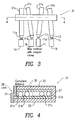
- FIG. 3 schematically illustrates an embodiment of a clamping instrument 31 according to the present invention.
- the instrument 31 engages, aligns and restrains the positions of the moment arms 21 by clamping the arms 21 in the distal region outside the patient's body.
- Figure 4 shows a top schematic view, related to Figure 3 , of the distal end of the moment arms 21a-21d and of the clamping instrument 31.
- the instrument 31 has longitudinal jaws 33 that are capable of being moved toward and away from each other in the lateral left and right directions to clamp onto the moment arms 21 and consequently align and restrain them.
- Each jaw 33 has a compliant material 35, such as a polymer or rubber, to conform to each moment arm 21 and accept the arms at various inferior-superior angles along the length of the jaws 35. The compliant material assists in gripping the moment arms 21.
- End portions 37 of the clamping instrument 31 connect the jaws 33 to complete an approximately rectangular structure having a central opening for the moment arms 21.
- a first end portion 37 incorporates a hinge or other mechanism for allowing the jaws to come together and a second end portion 37 incorporates, in the preferred embodiment, a latching mechanism or other closing mechanism that restrains the jaws 33 in the closed position.
- the clamping instrument 31, once closed on the moment arms 21, are capable of being moved toward and away from each other in the lateral left and right directions to align and restrain the moment arms 21.
- the clamping instrument 31 has two different functions for aligning the vertebrae.
- the first alignment is achieved by the closing and latching of the jaws 33 as shown by the relative rotations of the moment arms 21 shown between Figures 2 and 4 .
- moment arm 21b is rotated leftward relative to arm 21a
- moment arm 21c rightward relative to arm 21b and so on. Consequently, each vertebra is rotated relative to adjacent vertebrae to achieve an initial rotation within the instrumented segment of vertebrae.
- the degree of initial rotation for each vertebra 1 depends primarily on the positioning and orientation of each pedicle screw assembly 11.
- a special moment arm 21 with an offset distal portion may be used to increase or decrease the preliminary rotation of a given vertebra 1.
- the second alignment is achieved by manually rotating the clamping instrument 31 and the clamped moment arms 21 together to align the instrumented spinal segment.
- the clamping instrument 31 can achieve rotation both on a vertebra-to-vertebra basis and of an entire segment of the spine relative to the rest of the spine.
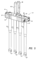
- Figure 5 shows a perspective view of a preferred embodiment of the invention with the clamping instrument 31 restraining four moment arms 21, each of which has a passage 27 at its proximal end to accommodate a spinal rod.
- the handles 45 serve the dual purposes of assisting in the closing of the jaws for the initial rotation and then allowing manipulation of the entire instrument for the final rotation.
- the handles 45 may be placed in any suitable position on the clamping instrument 31. In the illustrated embodiment, the handles 45 are shown in a central location, but in other embodiments these may be closer to or at the latch end opposite the hinge end.
- hinge 41 is at one end of the clamping instrument 31, and a latch 43 is at the opposite end.
- no latch is required as the handles can hold the instrument in the closed position when being held by a surgeon or surgeon's assistant.
- a latching device can be provided on or associated with the handles as opposed to directly on the jaws of the clamping instruments.
- the instrument 31 may accommodate the moment arms 21 at various angles in the inferior/superior plane.
- the resilient material 35 assists in this regard as it conforms to and grips the arms 21 at various angles.
- the instrument 31 may be also be used in a left-right orientation, and the moment arms 21a and 21d may be attached to pedicle screws on either side of the spinous process of the same vertebra. This arrangement creates a triangulated structure that can apply a greater torque to a vertebra while decreasing the bending moment on the pedicle screws.
- This approach can be used in conjunction with a second instrument 31 oriented in the superior-inferior direction to first create an initial alignment using the first instrument 31 and then restrain the vertebra with respect to other vertebrae using the second instrument 31.
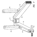
- Figure 7 shows the clamping instrument 21 in an open position and more clearly shows portions of its structure, particularly the hinge and latching structures.
- a spring-loaded hinge biased toward the open position is employed.
- a spring-loaded ratchet and pawl type latch 43 is employed.
- the clamping instrument 31 can be arranged about the moment arms 21, i.e., extension tubes, closed and latched, all with one hand. Disengagement of the latch 43 is facilitated by the latch extension and finger grip which lies outside of one jaw. A simple depression of this extended finger grip portion will disengage the ratchet and pawl arrangement.
Abstract
Description
- The present application claims the benefit of Application Serial No.
60/930,770, filed May 18, 2007 - The present invention relates generally to an alignment linkage such as a direct vertebral rotation instrument for creating, restraining and/or maintaining horizontal rotation of the vertebrae during posterior spinal fusion operations. The present invention also relates to a method for creating, restraining and/or maintaining horizontal rotation of the vertebrae during posterior spinal fusion operations.
- During spine surgery for conditions such as scoliosis, the surgeon seeks to achieve a three-dimensional correction of the spinal column shape by realigning and instrumenting the vertebrae in order to achieve an eventual fusion of the vertebral bodies in the desired alignment. Typically, the misalignment of the patient's vertebral bodies is readily apparent in the sagittal and coronal planes, either visually or by radiography. More difficult to see and correct is rotational misalignment of the vertebrae about the axis in the defined along the length of the spine. This rotation is often characterized in the scoliosis patient by projection of the ribs of the back creating a so-called rib hump on one side of the back caused by the rotation of the thoracic vertebrae and the attached ribs. While the axis of rotation actually changes along the length of the spine due to the spines natural curvature, for convenience of discussion the axis will be discussed as if it is a vertical line.
- In order to correct such a rotational misalignment, the surgeon must axially rotate the vertebrae in the opposite direction so that they are correctly oriented about the longitudinal axis of the spine. A corrective rotation of this type is often referred to as a "derotation."
- Direct vertebral rotation, hereinafter "DVR," is one method of horizontally rotating and re-aligning vertebral bodies. To use DVR, screws are implanted in the pedicles of the vertebrae and then a horizontal torque is applied by a lever arm or extension tube mounted to the screw head. As mentioned above, the indication is frequently scoliosis, but other deformity issues may be addressed through DVR. Tubular lever arms are then placed on the screws in line with the axis of the screw. A force is then applied to the lever arms to rotate the spinal vertebrae. This brings the vertebrae into the desired positions and in line with one another. The surgeon and the surgeon's assistants face the difficult task of manually rotating and aligning the various lever arms to eventually fasten the pedicle screw assemblies to rods and form a construct holding the vertebrae in the desired alignment.
- Polyaxial pedicle screw assemblies have, by way of example, a cage shaped to receive a bone screw, a rod and a blocker or set screw engaging screw threads. Generally, cages have two arms that extend away from the screw and define a slot through which the rod can pass transverse to the axis of the cage. Often, such cages are referred to as tulip-shaped. The cage can move polyaxially about the head of the bone screw until the assembly is fixed in a position. Once the rod is in place, the blocker is threaded within or on the outside of the cage. The blocker engages, directly or indirectly, the rod which in turn engages the head of the bone screw seated in the cage or engages the cage itself. The blocker thus locks or immobilizes the assembly.
- A monoaxial pedicle screw assembly generally includes a bone screw with an integral cage or head to receive the rod and blocker or nut.
- For DVR, the lever arms apply torque to the bone screw and the bone screw, in turn, applies the torque to the vertebrae. Either a polyaxial or monoaxial screw assembly may be used. The lever must fit tightly and grasp the screw head in order to apply the torque. If a polyaxial screw assembly is used, the head should be immobilized in the direction of axial rotation to allow the transmission of torque. A polyaxial screw also has a limited extent of free travel and can create torque on the vertebra once the range of movement of the head is exceeded.
- The present invention fills the need described above by providing a system and method for rotation of vertebral segments for posterior spinal fusion.
- The invention is directed to an instrument and associated method that aligns and holds the DVR lever arms relative to each other to achieve an initial axial alignment of a segment of vertebrae and allow the DVR rotation by rotating the instrument and lever arms together.
- Joining the lever arms or extension tubes with such a clamping instrument allows the surgeon to more uniformly and easily rotate the tubes together and to stepwise achieve a relative orientation of a segment of vertebrae. The segment of vertebra to be aligned can be aligned collectively relative to adjacent spinal segments.
- In one aspect the invention teaches a method of direct vertebral rotation, wherein the steps include attaching pedicle screws to at least two vertebrae to be aligned and attaching a lever to each of the pedicle screws. The levers are positioning between jaws of a direct vertebral rotation instrument and the jaws held in closed position. The jaws are brought together to rotate the vertebrae to be aligned relative to each other, and the vertebrae to be aligned are collectively rotated relative to adjacent spinal segments by rotating the direct vertebral rotation instrument.
- In another aspect the invention teaches a direct vertebral rotation instrument comprising a first jaw; a second jaw; a hinge connecting the first jaw and the second jaw; and a lock for locking the first jaw to the second jaw.
- In yet another aspect the invention teaches a system for direct vertebral rotation having at least two pedicle screws. The system also includes at least two levers attachable to the pedicle screws and a clamping instrument configured to clamp the levers.
- In one aspect of the present invention, the instrument has substantially parallel jaws to engage or clamp the lever arms in relative alignment for manipulation.
- In another aspect of the invention, the jaws of the instrument have a compliant material for interface with the lever arms in order to assist in gripping the lever arms and thus facilitate the effective adjustment of the longitudinal position of the lever arms.
- A further aspect of the invention includes the method of rotating vertebrae located within a patient's body about the spinal axis by: implanting a first pedicle screw on a first vertebra; implanting a second pedicle screw on a second vertebra; attaching a first moment arm and a second moment arm to the first screw and the second screw, respectively; locking the first moment arm and a second moment arm in a preliminary angular orientation with respect to the spinal axis by applying pressure using the opposing jaws of an instrument to align and restrain said moment arms; and rotating the instrument, arms and vertebra relative to the spinal axis.
- The present invention may be reduced to practice by a clamping instrument which includes elongate jaws having opposed interior faces and being hingeably or rotatably connected at one end or interior from one end, the jaws having an open position and a closed position, the open position facilitating the instrument to be arranged about a plurality of pedicle screw extension tubes or other lever arms associated with vertebra. The instrument in its closed position holds and initially aligns the lever arms on the interior faces of the jaws.
- In another aspect of the present invention, the above-described instrument includes handles to facilitate at least the closing of the jaws. The handles may be in the central area of the jaws and extend transverse to the elongate axis of the jaws, or may be displaced towards or at one end of the jaws, or even as an extension generally in alignment with the elongate axis of the jaws, or a portion of the jaws themselves may serve as portions of handles.
- In another aspect of the present invention, the jaws are hingeably connected at one end or are located interiorly from one end and include a spring mechanism to hold the jaws in a normally open position. This normally open position facilitates arrangement of the jaws about the extension tubes or lever arms to be clamped within the jaws. The hinge may be integral with one or both jaws, or may be a separate element connected to the jaws.
- In another aspect of the present invention, the closing mechanism is provided to hold the jaws in a closed position such that a surgeon or surgeon's assistant does not need to hold the handles together in order to maintain the instrument in a closed position. In one embodiment, a closing mechanism may be a latching mechanism provided anywhere along the jaws, or even on the handles themselves. In a preferred embodiment, a latching mechanism is provided at the end of the jaws opposite the hinge mechanism, and comprises a pawl and ratchet arrangement which automatically latches the jaws as the jaws are closed. The latching mechanism may have an extension with a finger grip, which may simply be a surface designed to facilitate gripping of one's finger (knurling, raised gripping ribs, etc.). The finger gripping portion may extend laterally outside of one of the jaws such that a depression on that portion will release the pawl and ratchet mechanism.
- In another aspect of the present invention, the interior faces of the jaws have a surface to facilitate gripping the extension tubes or lever arms. In a preferred embodiment, this may be a compliant material such as rubber. The coefficient of friction of such a material should facilitate the gripping of the lever arms, and the material may also include compliancy such that the lever arms are, upon undergoing a clamping force, forced into the material for gripping purposes. The compliance also allows the lever arms to be gripped at various angles and positions along the length of the jaws.
- In another aspect of the present invention, a method includes the use of the above broadly-described instrument by surrounding a plurality of lever arms with a normally open instrument, positioning the instrument about the lever arms, closing the instrument such that the jaws clamp the lever arms, and manually applying a torque and otherwise manipulating the instrument in order to manipulate the lever arms and thus the vertebra to which the lever arms are connected, directly or indirectly. The clamping of the jaws may achieve an initial desired alignment of the lever arms and vertebrae and then the entire assembly of the lever arms and vertebrae may be further rotated to the final position. The method may also include the steps of fixing spinal rods or other fixation devices arranged with respect to the vertebra to maintain the vertebra in the aligned position, and subsequently releasing the clamping instrument and removing the same from the lever arms.
-
-
Figure 1 is a schematic right side view of four adjacent vertebrae of a spine, with pedicle screws and lever arms as used in DVR. -
Figure 2 is a plan view as inFigure 1 showing the lever arms and establishing a coordinate system relative to the human body. -
Figure 3 is a schematic right side view of four adjacent vertebrae of a spine, with pedicle screws, lever arms and an instrument according to the present invention. -
Figure 4 is a plan view as inFigure 3 showing the lever arms and instrument of the present invention. -
Figure 5 is a perspective left side view of four lever arms and an instrument according to the present invention. -
Figure 6 is a perspective left side view of two lever arms and an instrument according to the present invention. -
Figure 7 is a perspective view of an instrument according to the present invention in the open position. - Referring to
Figure 1 , the portion of the spine illustrated includes afirst vertebra 1a, which may be the T10 (Tenth Thoracic) vertebra of a patient, asecond vertebra 1b, which may be the T9 (Ninth Thoracic) vertebra of a patient, athird vertebra 1c, which may be the T8 (Eighth Thoracic) vertebra of a patient, and afourth vertebra 1d, which may be the T7 (Seventh Thoracic) vertebra of a patient. The systems and methods described hereafter may be applicable to any vertebra or vertebrae of the spine and/or the sacrum (not shown). In this application, the term "vertebra" may be broadly interpreted to include the sacrum although rotation is only attempted relative to the sacrum and the sacrum itself is not rotated. -
Pedicle screw assemblies 11a-11d (collectively screws 11) are implanted in the associated pedicles of thevertebrae 1a-1d. In one of many pedicle screw arrangements,pedicle screw assemblies 11a-11d each have acage 13 shaped to receive a rod and a set screw that passes through an aperture of the cage. Each screw 11 also has a threadedshaft 15 which is threaded into the vertebra 1 to implant the pedicle screw assembly. - Connected to the
head 13 of each screw 11 aremoment arms 21a-21d (collectively moment arms 21). In this embodiment the moment arms 21 are cannulated tubes having an opendistal end 23 allowing placement of objects such as the aforementioned locking screws and suitable locking screw drivers through the cannulae of the tubes. These moment arms 21 serve as lever arms in connection with the vertebral rotation system herein. Theproximal end 25 of each moment arm 21 removeably engages thehead 13 of the respective pedicle screw assembly 11 so as to be able to apply torque to the vertebrae 1. -
Figure 2 shows a top view, related toFigure 1 , of the distal end of themoment arms 21a-21d. Also shown is a coordinate system defining superior and inferior directions along the spinal axis and left and right directions in the plane defined by the spine axis A-A. Thus, the torque to be applied by the moment arms 21 is in the left or right direction. It can be seen that the distal ends 23 of the moment arms 21 are offset in various left-right and inferior-superior directions depending on the initial geometry of the patient's spine and the pedicle screw placements as determined by the surgeon. -
Figure 3 schematically illustrates an embodiment of a clampinginstrument 31 according to the present invention. Theinstrument 31 engages, aligns and restrains the positions of the moment arms 21 by clamping the arms 21 in the distal region outside the patient's body. -
Figure 4 shows a top schematic view, related toFigure 3 , of the distal end of themoment arms 21a-21d and of the clampinginstrument 31. Theinstrument 31 haslongitudinal jaws 33 that are capable of being moved toward and away from each other in the lateral left and right directions to clamp onto the moment arms 21 and consequently align and restrain them. Eachjaw 33 has acompliant material 35, such as a polymer or rubber, to conform to each moment arm 21 and accept the arms at various inferior-superior angles along the length of thejaws 35. The compliant material assists in gripping the moment arms 21. -
End portions 37 of the clampinginstrument 31 connect thejaws 33 to complete an approximately rectangular structure having a central opening for the moment arms 21. Afirst end portion 37 incorporates a hinge or other mechanism for allowing the jaws to come together and asecond end portion 37 incorporates, in the preferred embodiment, a latching mechanism or other closing mechanism that restrains thejaws 33 in the closed position. The clampinginstrument 31, once closed on the moment arms 21, are capable of being moved toward and away from each other in the lateral left and right directions to align and restrain the moment arms 21. - The clamping
instrument 31 has two different functions for aligning the vertebrae. The first alignment is achieved by the closing and latching of thejaws 33 as shown by the relative rotations of the moment arms 21 shown betweenFigures 2 and4 . Thus,moment arm 21b is rotated leftward relative toarm 21a,moment arm 21c rightward relative toarm 21b and so on. Consequently, each vertebra is rotated relative to adjacent vertebrae to achieve an initial rotation within the instrumented segment of vertebrae. If straight moment arms 21 are used, the degree of initial rotation for each vertebra 1 depends primarily on the positioning and orientation of each pedicle screw assembly 11. If desired, a special moment arm 21 with an offset distal portion may be used to increase or decrease the preliminary rotation of a given vertebra 1. - The second alignment is achieved by manually rotating the clamping
instrument 31 and the clamped moment arms 21 together to align the instrumented spinal segment. Thus, the clampinginstrument 31 can achieve rotation both on a vertebra-to-vertebra basis and of an entire segment of the spine relative to the rest of the spine. -
Figure 5 shows a perspective view of a preferred embodiment of the invention with the clampinginstrument 31 restraining four moment arms 21, each of which has apassage 27 at its proximal end to accommodate a spinal rod. Mounted to thelongitudinal jaws 33 are handles 45. Thehandles 45 serve the dual purposes of assisting in the closing of the jaws for the initial rotation and then allowing manipulation of the entire instrument for the final rotation. Thehandles 45 may be placed in any suitable position on the clampinginstrument 31. In the illustrated embodiment, thehandles 45 are shown in a central location, but in other embodiments these may be closer to or at the latch end opposite the hinge end. - As also seen in
Figure 6 , hinge 41 is at one end of the clampinginstrument 31, and alatch 43 is at the opposite end. In one embodiment, no latch is required as the handles can hold the instrument in the closed position when being held by a surgeon or surgeon's assistant. In another embodiment, a latching device can be provided on or associated with the handles as opposed to directly on the jaws of the clamping instruments. - As shown best in
Figure 6 , theinstrument 31 may accommodate the moment arms 21 at various angles in the inferior/superior plane. Theresilient material 35 assists in this regard as it conforms to and grips the arms 21 at various angles. As shown, theinstrument 31 may be also be used in a left-right orientation, and themoment arms second instrument 31 oriented in the superior-inferior direction to first create an initial alignment using thefirst instrument 31 and then restrain the vertebra with respect to other vertebrae using thesecond instrument 31. -
Figure 7 shows the clamping instrument 21 in an open position and more clearly shows portions of its structure, particularly the hinge and latching structures. In the preferred embodiment, a spring-loaded hinge biased toward the open position is employed. Also in a preferred embodiment, a spring-loaded ratchet andpawl type latch 43 is employed. Thus, one-handed operation is facilitated. The clampinginstrument 31 can be arranged about the moment arms 21, i.e., extension tubes, closed and latched, all with one hand. Disengagement of thelatch 43 is facilitated by the latch extension and finger grip which lies outside of one jaw. A simple depression of this extended finger grip portion will disengage the ratchet and pawl arrangement. - Although the invention herein has been described with reference to particular embodiments, it is to be understood that these embodiments are merely illustrative of the principles and applications of the present invention. It is therefore to be understood that numerous modifications may be made to the illustrative embodiments and that other arrangements may be devised without departing from the spirit and scope of the present invention.
- The following numbered examples describe features in accordance with various embodiments of the method as further described above:
- Example 1: A method of direct vertebral rotation comprising:
- attaching pedicle screws to at least two vertebrae to be aligned;
- attaching a lever to each of the pedicle screws;
- positioning the levers between jaws of a direct vertebral rotation instrument;
- holding the jaws in closed position;
- rotating the vertebrae to be aligned relative to each other by bringing the jaws together; and
- collectively rotating the vertebrae to be aligned relative to adjacent spinal segments by rotating the direct vertebral rotation instrument.
- Example 2. The method of example 1, further comprising latching the jaws together.
- Example 3. The method of example 1, further comprising:
- maintaining the position of the vertebrae relative to each other.
- Example 4.The method of example 1, further comprising:
- attaching a lever with an offset distal portion to at least one pedicle screw.
- Example 5.The method of example 2, wherein the jaws have a first layer and a second layer.
- Example 6.The method of example 2, wherein at least a portion of the jaws is compliant.
- Example 7. The method of example 2, wherein at least a portion of the jaws is made from rubber or polymer.
- Example 8. The method of example 2, wherein the direct vertebral rotation instrument has handles configured to be held in a hand.
- Example 9. The method of example 2, wherein the direct vertebral rotation instrument has a hinge configured to connect the jaws.
- Example 10. The method of example 2, wherein the direct vertebral rotation instrument has a lock configured to latch the jaws together.
- Example 11. A direct vertebral rotation instrument comprising:
- a first jaw;
- a second jaw;
- a hinge connecting the first jaw and the second jaw; and
- a lock for locking the first jaw to the second jaw.
- Example 12. The instrument of example 11, further comprising:
- handles attached to each of the first jaw and the second jaw, wherein the handles are configured to rotate the first jaw and the second jaw towards or away from each other.
- Example 13. The instrument of example 12, wherein the first jaw and the second jaw have a first layer and a second layer.
- Example 14. The instrument of example 13, wherein the first layer is compliant.
- Example 15. The instrument of example 13, wherein the first layer is made from a material selected from a group consisting of polymer and rubber.
- Example 16. A system for direct vertebral rotation comprising:
- at least two pedicle screws;
- at least two levers attachable to the pedicle screws; and
- a clamping instrument configured to clamp the levers.
- Example 17. The system of example 16, further comprising:
- a third lever, the third lever having an offset distal portion.
- Example 18. The system of example 17, wherein the clamping instrument comprises:
- a first jaw;
- a second jaw;
- a hinge connecting the first jaw and the second jaw;
- a lock for locking the first jaw to the second jaw; and handles attached to each of the first jaw and the second jaw, wherein the handles are configured to rotate the first jaw and the second jaw towards or away from each other.
- Example 19. The system of example 18, wherein the first jaw and the second jaw have a first layer and a second layer, and the first layer is compliant.
- Example 20. The system of example 18, wherein the first layer is made from polymer or rubber.
Claims (15)
- A system for direct vertebral rotation comprising:at least two levers (21), each of the levers being attachable to a pedicle screw (11) implanted in a vertebra of a spine such that each lever extends proximally from the respective pedicle screw; anda clamping instrument (31) configured to clamp the levers, the clamping instrument including a first jaw (33) and a second jaw (33), each of the first and second jaws including an inner portion facing towards the other of the first and second jaws, wherein the first and second jaws are movable relative to one another to a closed position in which a plurality of the levers are receivable between the first and second jawscharacterized in that:the inner portion of each of the first and second jaws includes a compliant material (35), and the compliant material of the first and second jaws is configured to conform to the levers received between the first and second jaws when the first and second jaws are in the closed position.
- The system of claim 1, wherein the clamping instrument (31) further comprises handles (45) attached to each of the first jaw (33) and the second jaw (33), wherein the handles are configured to move the first jaw and the second jaw towards or away from each other.
- The system of claim 2, wherein the handles (45) extend transverse to an elongate axis of the respective first and second jaws (33).
- The system of claim 2, wherein the handles (45) are located in a central area of the respective first and second jaws (33).
- The system of claim 1, wherein the compliant material (35) is selected from a group consisting of polymer and rubber.
- The system of claim 1, wherein the clamping instrument (31) further comprises a lock (43) for locking the first jaw (33) to the second jaw (33) in the closed position.
- The system of claim 6, wherein the lock (43) comprises a pawl and ratchet arrangement which automatically latches the first and second jaws (33) as the first and second jaws are moved to the closed position.
- The system of claim 7, wherein the lock (43) includes a finger gripping portion extending laterally outside of one of the first and second jaws (33) such that depression of the finger gripping portion releases the pawl and ratchet arrangement.
- The system of claim 1, wherein the clamping instrument (31) further comprises a hinge (41) connecting the first jaw and the second jaw, and wherein the first and second jaws (33) are movable between an open position and the closed position by rotating about the hinge.
- The system of claim 9, wherein the hinge (41) is spring-loaded so as to bias the first and second jaws (33) into the open position.
- The system of claim 9, wherein the clamping instrument (31) further comprises a lock (43) for locking the first jaw (33) to the second jaw (33) in the closed position, wherein the lock (42) is located at an opposite end of the first and second jaws (33) from the hinge (41).
- The system of claim 1, further comprising the at least two pedicle screws (11).
- The system of claim 12, further comprising a rod adapted to be received by a cage (13) of each of the at least two pedicle screws (11).
- The system of claim 1, further comprising:a third lever (21), the third lever having an offset distal portion.
- The system of claim 1, wherein the first and second jaws (33) are capable of being moved toward and away from each other to clamp onto the levers (21) in order to align and restrain the levers.
Priority Applications (1)
| Application Number | Priority Date | Filing Date | Title |
|---|---|---|---|
| EP17176613.2A EP3272299B1 (en) | 2007-05-18 | 2008-05-16 | Apparatus for direct vertebral rotation |
Applications Claiming Priority (2)
| Application Number | Priority Date | Filing Date | Title |
|---|---|---|---|
| US93077007P | 2007-05-18 | 2007-05-18 | |
| EP08767770.4A EP2152178B1 (en) | 2007-05-18 | 2008-05-16 | Apparatus for direct vertebral rotation |
Related Parent Applications (1)
| Application Number | Title | Priority Date | Filing Date |
|---|---|---|---|
| EP08767770.4A Division EP2152178B1 (en) | 2007-05-18 | 2008-05-16 | Apparatus for direct vertebral rotation |
Related Child Applications (1)
| Application Number | Title | Priority Date | Filing Date |
|---|---|---|---|
| EP17176613.2A Division EP3272299B1 (en) | 2007-05-18 | 2008-05-16 | Apparatus for direct vertebral rotation |
Publications (2)
| Publication Number | Publication Date |
|---|---|
| EP3009089A1 true EP3009089A1 (en) | 2016-04-20 |
| EP3009089B1 EP3009089B1 (en) | 2017-06-21 |
Family
ID=40073129
Family Applications (3)
| Application Number | Title | Priority Date | Filing Date |
|---|---|---|---|
| EP08767770.4A Active EP2152178B1 (en) | 2007-05-18 | 2008-05-16 | Apparatus for direct vertebral rotation |
| EP17176613.2A Active EP3272299B1 (en) | 2007-05-18 | 2008-05-16 | Apparatus for direct vertebral rotation |
| EP15187397.3A Active EP3009089B1 (en) | 2007-05-18 | 2008-05-16 | System for direct vertebral rotation |
Family Applications Before (2)
| Application Number | Title | Priority Date | Filing Date |
|---|---|---|---|
| EP08767770.4A Active EP2152178B1 (en) | 2007-05-18 | 2008-05-16 | Apparatus for direct vertebral rotation |
| EP17176613.2A Active EP3272299B1 (en) | 2007-05-18 | 2008-05-16 | Apparatus for direct vertebral rotation |
Country Status (4)
| Country | Link |
|---|---|
| US (5) | US8465529B2 (en) |
| EP (3) | EP2152178B1 (en) |
| JP (1) | JP5190111B2 (en) |
| WO (1) | WO2008144000A1 (en) |
Families Citing this family (29)
| Publication number | Priority date | Publication date | Assignee | Title |
|---|---|---|---|---|
| US7776072B2 (en) | 2004-12-30 | 2010-08-17 | Barry Mark A | System and method for aligning vertebrae in the amelioration of aberrant spinal column deviation conditions |
| US9339301B2 (en) | 2004-12-30 | 2016-05-17 | Mark A. Barry | System and method for aligning vertebrae in the amelioration of aberrant spinal column deviation conditions |
| US9675385B2 (en) | 2005-04-12 | 2017-06-13 | Nathan C. Moskowitz | Spinous process staple with interdigitating-interlocking hemi-spacers for adjacent spinous process separation and distraction |
| EP2152178B1 (en) * | 2007-05-18 | 2015-09-30 | Stryker Spine | Apparatus for direct vertebral rotation |
| CN201344760Y (en) * | 2008-12-24 | 2009-11-11 | 佛山市南海祥旺光学电子制品有限公司 | Angle adjustment structure |
| US9439691B2 (en) * | 2009-05-22 | 2016-09-13 | Clifford Tribus | Fixation-based surgery |
| WO2011023212A1 (en) * | 2009-08-28 | 2011-03-03 | Stryker Trauma Ag | Surgical clamping device |
| US8986349B1 (en) | 2009-11-11 | 2015-03-24 | Nuvasive, Inc. | Systems and methods for correcting spinal deformities |
| WO2011127065A1 (en) * | 2010-04-06 | 2011-10-13 | Seaspine, Inc. | System and methods for correcting spinal deformities |
| WO2012034005A2 (en) | 2010-09-09 | 2012-03-15 | Synthes Usa, Llc | Vertebral adjustment systems for spine alignment |
| US8936605B2 (en) | 2011-12-30 | 2015-01-20 | Blackstone Medical, Inc. | Direct vertebral rotation tool and method of using same |
| US9125703B2 (en) * | 2012-01-16 | 2015-09-08 | K2M, Inc. | Rod reducer, compressor, distractor system |
| US8951257B2 (en) * | 2012-02-15 | 2015-02-10 | Warsaw Orthopedic, Inc. | Spinal correction system and method |
| US9622876B1 (en) | 2012-04-25 | 2017-04-18 | Theken Spine, Llc | Expandable support device and method of use |
| US10098665B2 (en) | 2012-08-01 | 2018-10-16 | DePuy Synthes Products, Inc. | Spine derotation system |
| US9763702B2 (en) | 2012-11-16 | 2017-09-19 | DePuy Synthes Products, Inc. | Bone fixation assembly |
| US9241742B2 (en) * | 2013-03-14 | 2016-01-26 | DePuy Synthes Products, Inc. | Methods and devices for polyaxial screw alignment |
| US9408716B1 (en) | 2013-12-06 | 2016-08-09 | Stryker European Holdings I, Llc | Percutaneous posterior spinal fusion implant construction and method |
| US10159579B1 (en) | 2013-12-06 | 2018-12-25 | Stryker European Holdings I, Llc | Tubular instruments for percutaneous posterior spinal fusion systems and methods |
| US9744050B1 (en) * | 2013-12-06 | 2017-08-29 | Stryker European Holdings I, Llc | Compression and distraction system for percutaneous posterior spinal fusion |
| FR3018678B1 (en) * | 2014-03-20 | 2016-03-11 | Spineway | SURGICAL ASSEMBLY, BONE ANCHORING SCREW AND DEVICE FOR EXTENSION OF SUCH SCREWS FORMING PART OF SAID SURGICAL ASSEMBLY |
| WO2015195843A2 (en) * | 2014-06-17 | 2015-12-23 | Nuvasive, Inc. | Systems and methods for planning, performing, and assessing spinal correction during surgery |
| US9681899B2 (en) * | 2015-03-23 | 2017-06-20 | Globus Medical, Inc. | Orthopedic derotation devices and methods of installation thereof |
| US11602379B2 (en) * | 2015-03-23 | 2023-03-14 | Globus Medical, Inc. | Orthopedic derotation devices and methods of installation thereof |
| DE102015212056B3 (en) * | 2015-06-29 | 2016-09-01 | Silony Medical International AG | Apparatus for performing distraction or compression of vertebral bodies in a spinal surgery |
| KR101703003B1 (en) * | 2015-08-31 | 2017-02-06 | 주식회사 메드릭스 | Screw holder with joint for minimal invasive surgery and apparatus of minimal invasive surgery using this |
| US10779866B2 (en) | 2016-12-29 | 2020-09-22 | K2M, Inc. | Rod reducer assembly |
| EP3517062B1 (en) * | 2018-01-26 | 2021-03-17 | Aesculap AG | Spinal repositioning instrument and spinal repositioning system |
| US11849981B2 (en) | 2019-01-30 | 2023-12-26 | Medos International Sarl | Systems and methods for en bloc derotation of a spinal column |
Citations (5)
| Publication number | Priority date | Publication date | Assignee | Title |
|---|---|---|---|---|
| JPH1014934A (en) * | 1996-07-01 | 1998-01-20 | Mizuho Ika Kogyo Kk | Apparatus for fixing and correcting spine corrector on spine outside human body |
| FR2757761A1 (en) * | 1996-12-27 | 1998-07-03 | Stryker France Sa | SPINE OTEOSYNTHESIS SYSTEM WITH POSITION ADJUSTMENT |
| US20050245928A1 (en) * | 2004-05-03 | 2005-11-03 | Innovative Spinal Technologies | System and method for displacement of bony structures |
| WO2006096516A2 (en) * | 2005-03-04 | 2006-09-14 | Depuy Spine, Inc | Instruments and methods for manipulating a vertebra |
| WO2006104813A2 (en) * | 2005-03-30 | 2006-10-05 | Warsaw Orthopedic, Inc. | Instrumentation and methods for reducing spinal deformities |
Family Cites Families (32)
| Publication number | Priority date | Publication date | Assignee | Title |
|---|---|---|---|---|
| US2468823A (en) * | 1948-01-13 | 1949-05-03 | Edgar M Housepian | Clamp |
| US3503397A (en) * | 1967-09-21 | 1970-03-31 | American Hospital Supply Corp | Atraumatic surgical clamp |
| US5219349A (en) | 1991-02-15 | 1993-06-15 | Howmedica, Inc. | Spinal fixator reduction frame |
| DE4202748A1 (en) | 1992-01-31 | 1993-08-05 | Kluger Patrick | SPINAL IMPLANT AND REPOSITION INSTRUMENTS |
| US5281223A (en) | 1992-09-21 | 1994-01-25 | Ray R Charles | Tool and method for derotating scoliotic spine |
| US5814038A (en) * | 1995-06-07 | 1998-09-29 | Sri International | Surgical manipulator for a telerobotic system |
| US6200263B1 (en) * | 1998-01-23 | 2001-03-13 | United States Surgical Corporation | Surgical instrument holder |
| DE60032225T2 (en) * | 1999-03-30 | 2007-09-13 | Howmedica Osteonics Corp. | APPARATUS FOR STABILIZING THE SPINE |
| US6287250B1 (en) * | 1999-09-21 | 2001-09-11 | Origin Medsystems, Inc. | Method and apparatus for cardiac lifting during beating heart surgery using pericardial clips |
| US6530929B1 (en) * | 1999-10-20 | 2003-03-11 | Sdgi Holdings, Inc. | Instruments for stabilization of bony structures |
| WO2001056488A1 (en) | 2000-02-03 | 2001-08-09 | Rossiisky Nauchny Tsentr Vosstanovitelnaya Travmatologiya I Ortopediya Im. Akad. G.A.Ilizarova | Device for external trans perpendicular vertebral column fixation, method for use thereof and a medical clamp for implanting a fixing element |
| US6554831B1 (en) * | 2000-09-01 | 2003-04-29 | Hopital Sainte-Justine | Mobile dynamic system for treating spinal disorder |
| US6565568B1 (en) | 2000-09-28 | 2003-05-20 | Chaim Rogozinski | Apparatus and method for the manipulation of the spine and sacrum in the treatment of spondylolisthesis |
| AU2002248223A1 (en) | 2000-12-29 | 2002-07-24 | James Thomas | Vertebral alignment system |
| ITVI20010118A1 (en) * | 2001-05-23 | 2002-11-23 | Samec Divisione Costruzione Ma | METHOD AND MACHINE FOR THE STRETCHING OF ELECTRIC CABLES |
| US6511484B2 (en) * | 2001-06-29 | 2003-01-28 | Depuy Acromed, Inc. | Tool and system for aligning and applying fastener to implanted anchor |
| FR2831049B1 (en) * | 2001-10-18 | 2004-08-13 | Ldr Medical | PLATE FOR OSTEOSYNTHESIS DEVICE AND PRE-ASSEMBLY METHOD |
| US7182775B2 (en) * | 2003-02-27 | 2007-02-27 | Microline Pentax, Inc. | Super atraumatic grasper apparatus |
| WO2004082723A2 (en) * | 2003-03-23 | 2004-09-30 | Shifrin Edward G | Supplementary vascular clamp for the tool kit of an open approach stapler |
| JP2005169064A (en) * | 2003-05-22 | 2005-06-30 | Sohei Ebara | Surgical device for correction of spinal deformity, and method for using the same |
| US7918828B2 (en) * | 2003-11-28 | 2011-04-05 | Health Equipment Denmark Aps | Medical securing device |
| US7658753B2 (en) | 2004-08-03 | 2010-02-09 | K Spine, Inc. | Device and method for correcting a spinal deformity |
| US7776072B2 (en) | 2004-12-30 | 2010-08-17 | Barry Mark A | System and method for aligning vertebrae in the amelioration of aberrant spinal column deviation conditions |
| US7670358B2 (en) | 2004-12-30 | 2010-03-02 | Barry Mark A | System and method for aligning vertebrae in the amelioration of aberrant spinal column deviation conditions |
| US7758617B2 (en) * | 2005-04-27 | 2010-07-20 | Globus Medical, Inc. | Percutaneous vertebral stabilization system |
| GB0510111D0 (en) * | 2005-05-18 | 2005-06-22 | Photonics The | Patellar resection tool |
| US8894655B2 (en) * | 2006-02-06 | 2014-11-25 | Stryker Spine | Rod contouring apparatus and method for percutaneous pedicle screw extension |
| US7794464B2 (en) | 2006-02-09 | 2010-09-14 | Warsaw Orthopedic, Inc. | Spinal derotation instruments and methods |
| US7655008B2 (en) * | 2006-02-09 | 2010-02-02 | Warsaw Orthopedic, Inc. | Methods and instruments for spinal derotation |
| EP2066242B1 (en) * | 2006-09-25 | 2011-05-04 | Stryker Spine | Percutaneous compression and distraction system |
| EP2152178B1 (en) * | 2007-05-18 | 2015-09-30 | Stryker Spine | Apparatus for direct vertebral rotation |
| US8608746B2 (en) | 2008-03-10 | 2013-12-17 | DePuy Synthes Products, LLC | Derotation instrument with reduction functionality |
-
2008
- 2008-05-16 EP EP08767770.4A patent/EP2152178B1/en active Active
- 2008-05-16 EP EP17176613.2A patent/EP3272299B1/en active Active
- 2008-05-16 EP EP15187397.3A patent/EP3009089B1/en active Active
- 2008-05-16 US US12/152,834 patent/US8465529B2/en active Active
- 2008-05-16 JP JP2010508446A patent/JP5190111B2/en not_active Expired - Fee Related
- 2008-05-16 WO PCT/US2008/006330 patent/WO2008144000A1/en active Application Filing
-
2013
- 2013-05-08 US US13/889,847 patent/US9554832B2/en active Active
-
2016
- 2016-12-19 US US15/383,006 patent/US9974578B2/en active Active
-
2018
- 2018-04-27 US US15/964,270 patent/US11172965B2/en active Active
-
2021
- 2021-11-10 US US17/523,477 patent/US20220133365A1/en active Pending
Patent Citations (5)
| Publication number | Priority date | Publication date | Assignee | Title |
|---|---|---|---|---|
| JPH1014934A (en) * | 1996-07-01 | 1998-01-20 | Mizuho Ika Kogyo Kk | Apparatus for fixing and correcting spine corrector on spine outside human body |
| FR2757761A1 (en) * | 1996-12-27 | 1998-07-03 | Stryker France Sa | SPINE OTEOSYNTHESIS SYSTEM WITH POSITION ADJUSTMENT |
| US20050245928A1 (en) * | 2004-05-03 | 2005-11-03 | Innovative Spinal Technologies | System and method for displacement of bony structures |
| WO2006096516A2 (en) * | 2005-03-04 | 2006-09-14 | Depuy Spine, Inc | Instruments and methods for manipulating a vertebra |
| WO2006104813A2 (en) * | 2005-03-30 | 2006-10-05 | Warsaw Orthopedic, Inc. | Instrumentation and methods for reducing spinal deformities |
Also Published As
| Publication number | Publication date |
|---|---|
| US11172965B2 (en) | 2021-11-16 |
| US8465529B2 (en) | 2013-06-18 |
| EP2152178A1 (en) | 2010-02-17 |
| EP2152178B1 (en) | 2015-09-30 |
| WO2008144000A1 (en) | 2008-11-27 |
| US9974578B2 (en) | 2018-05-22 |
| EP2152178A4 (en) | 2013-04-03 |
| JP2010527650A (en) | 2010-08-19 |
| US20180310967A1 (en) | 2018-11-01 |
| US20080294206A1 (en) | 2008-11-27 |
| JP5190111B2 (en) | 2013-04-24 |
| US20220133365A1 (en) | 2022-05-05 |
| US20170224392A1 (en) | 2017-08-10 |
| US20130245694A1 (en) | 2013-09-19 |
| EP3272299A1 (en) | 2018-01-24 |
| EP3272299B1 (en) | 2020-05-13 |
| US9554832B2 (en) | 2017-01-31 |
| EP3009089B1 (en) | 2017-06-21 |
Similar Documents
| Publication | Publication Date | Title |
|---|---|---|
| US20220133365A1 (en) | Apparatus And Method For Direct Vertebral Rotation | |
| US20200197053A1 (en) | Reduction sleeve | |
| US11344340B2 (en) | Bi-planar persuader | |
| EP2768411B1 (en) | Derotation apparatus for treating spinal irregularities | |
| US8617165B2 (en) | Rod reducing instrument and methods of use thereof | |
| US8221474B2 (en) | Spinal derotation instruments and methods | |
| EP2460483B1 (en) | Surgical instrument | |
| US9173687B2 (en) | Fulcrum cap for spinal constructs | |
| US20130090692A1 (en) | Intraoperative spinal stabilization | |
| US20120221059A1 (en) | Cervical spine clamp | |
| US9351770B2 (en) | System and method for spinal deformity correction |
Legal Events
| Date | Code | Title | Description |
|---|---|---|---|
| PUAI | Public reference made under article 153(3) epc to a published international application that has entered the european phase |
Free format text: ORIGINAL CODE: 0009012 |
|
| 17P | Request for examination filed |
Effective date: 20150929 |
|
| AC | Divisional application: reference to earlier application |
Ref document number: 2152178 Country of ref document: EP Kind code of ref document: P |
|
| AK | Designated contracting states |
Kind code of ref document: A1 Designated state(s): AT BE BG CH CY CZ DE DK EE ES FI FR GB GR HR HU IE IS IT LI LT LU LV MC MT NL NO PL PT RO SE SI SK TR |
|
| GRAP | Despatch of communication of intention to grant a patent |
Free format text: ORIGINAL CODE: EPIDOSNIGR1 |
|
| RIC1 | Information provided on ipc code assigned before grant |
Ipc: A61B 17/70 20060101AFI20161026BHEP |
|
| INTG | Intention to grant announced |
Effective date: 20161117 |
|
| GRAS | Grant fee paid |
Free format text: ORIGINAL CODE: EPIDOSNIGR3 |
|
| GRAJ | Information related to disapproval of communication of intention to grant by the applicant or resumption of examination proceedings by the epo deleted |
Free format text: ORIGINAL CODE: EPIDOSDIGR1 |
|
| GRAL | Information related to payment of fee for publishing/printing deleted |
Free format text: ORIGINAL CODE: EPIDOSDIGR3 |
|
| INTC | Intention to grant announced (deleted) | ||
| GRAR | Information related to intention to grant a patent recorded |
Free format text: ORIGINAL CODE: EPIDOSNIGR71 |
|
| GRAA | (expected) grant |
Free format text: ORIGINAL CODE: 0009210 |
|
| INTG | Intention to grant announced |
Effective date: 20170510 |
|
| AC | Divisional application: reference to earlier application |
Ref document number: 2152178 Country of ref document: EP Kind code of ref document: P |
|
| AK | Designated contracting states |
Kind code of ref document: B1 Designated state(s): AT BE BG CH CY CZ DE DK EE ES FI FR GB GR HR HU IE IS IT LI LT LU LV MC MT NL NO PL PT RO SE SI SK TR |
|
| REG | Reference to a national code |
Ref country code: GB Ref legal event code: FG4D |
|
| REG | Reference to a national code |
Ref country code: CH Ref legal event code: EP |
|
| REG | Reference to a national code |
Ref country code: IE Ref legal event code: FG4D |
|
| REG | Reference to a national code |
Ref country code: AT Ref legal event code: REF Ref document number: 902234 Country of ref document: AT Kind code of ref document: T Effective date: 20170715 |
|
| REG | Reference to a national code |
Ref country code: DE Ref legal event code: R096 Ref document number: 602008050837 Country of ref document: DE |
|
| REG | Reference to a national code |
Ref country code: NL Ref legal event code: MP Effective date: 20170621 |
|
| PG25 | Lapsed in a contracting state [announced via postgrant information from national office to epo] |
Ref country code: HR Free format text: LAPSE BECAUSE OF FAILURE TO SUBMIT A TRANSLATION OF THE DESCRIPTION OR TO PAY THE FEE WITHIN THE PRESCRIBED TIME-LIMIT Effective date: 20170621 Ref country code: GR Free format text: LAPSE BECAUSE OF FAILURE TO SUBMIT A TRANSLATION OF THE DESCRIPTION OR TO PAY THE FEE WITHIN THE PRESCRIBED TIME-LIMIT Effective date: 20170922 Ref country code: FI Free format text: LAPSE BECAUSE OF FAILURE TO SUBMIT A TRANSLATION OF THE DESCRIPTION OR TO PAY THE FEE WITHIN THE PRESCRIBED TIME-LIMIT Effective date: 20170621 Ref country code: NO Free format text: LAPSE BECAUSE OF FAILURE TO SUBMIT A TRANSLATION OF THE DESCRIPTION OR TO PAY THE FEE WITHIN THE PRESCRIBED TIME-LIMIT Effective date: 20170921 Ref country code: LT Free format text: LAPSE BECAUSE OF FAILURE TO SUBMIT A TRANSLATION OF THE DESCRIPTION OR TO PAY THE FEE WITHIN THE PRESCRIBED TIME-LIMIT Effective date: 20170621 |
|
| REG | Reference to a national code |
Ref country code: LT Ref legal event code: MG4D |
|
| REG | Reference to a national code |
Ref country code: AT Ref legal event code: MK05 Ref document number: 902234 Country of ref document: AT Kind code of ref document: T Effective date: 20170621 |
|
| PG25 | Lapsed in a contracting state [announced via postgrant information from national office to epo] |
Ref country code: SE Free format text: LAPSE BECAUSE OF FAILURE TO SUBMIT A TRANSLATION OF THE DESCRIPTION OR TO PAY THE FEE WITHIN THE PRESCRIBED TIME-LIMIT Effective date: 20170621 Ref country code: LV Free format text: LAPSE BECAUSE OF FAILURE TO SUBMIT A TRANSLATION OF THE DESCRIPTION OR TO PAY THE FEE WITHIN THE PRESCRIBED TIME-LIMIT Effective date: 20170621 Ref country code: NL Free format text: LAPSE BECAUSE OF FAILURE TO SUBMIT A TRANSLATION OF THE DESCRIPTION OR TO PAY THE FEE WITHIN THE PRESCRIBED TIME-LIMIT Effective date: 20170621 Ref country code: BG Free format text: LAPSE BECAUSE OF FAILURE TO SUBMIT A TRANSLATION OF THE DESCRIPTION OR TO PAY THE FEE WITHIN THE PRESCRIBED TIME-LIMIT Effective date: 20170921 |
|
| PG25 | Lapsed in a contracting state [announced via postgrant information from national office to epo] |
Ref country code: CZ Free format text: LAPSE BECAUSE OF FAILURE TO SUBMIT A TRANSLATION OF THE DESCRIPTION OR TO PAY THE FEE WITHIN THE PRESCRIBED TIME-LIMIT Effective date: 20170621 Ref country code: SK Free format text: LAPSE BECAUSE OF FAILURE TO SUBMIT A TRANSLATION OF THE DESCRIPTION OR TO PAY THE FEE WITHIN THE PRESCRIBED TIME-LIMIT Effective date: 20170621 Ref country code: RO Free format text: LAPSE BECAUSE OF FAILURE TO SUBMIT A TRANSLATION OF THE DESCRIPTION OR TO PAY THE FEE WITHIN THE PRESCRIBED TIME-LIMIT Effective date: 20170621 Ref country code: EE Free format text: LAPSE BECAUSE OF FAILURE TO SUBMIT A TRANSLATION OF THE DESCRIPTION OR TO PAY THE FEE WITHIN THE PRESCRIBED TIME-LIMIT Effective date: 20170621 Ref country code: AT Free format text: LAPSE BECAUSE OF FAILURE TO SUBMIT A TRANSLATION OF THE DESCRIPTION OR TO PAY THE FEE WITHIN THE PRESCRIBED TIME-LIMIT Effective date: 20170621 |
|
| PG25 | Lapsed in a contracting state [announced via postgrant information from national office to epo] |
Ref country code: ES Free format text: LAPSE BECAUSE OF FAILURE TO SUBMIT A TRANSLATION OF THE DESCRIPTION OR TO PAY THE FEE WITHIN THE PRESCRIBED TIME-LIMIT Effective date: 20170621 Ref country code: IS Free format text: LAPSE BECAUSE OF FAILURE TO SUBMIT A TRANSLATION OF THE DESCRIPTION OR TO PAY THE FEE WITHIN THE PRESCRIBED TIME-LIMIT Effective date: 20171021 Ref country code: IT Free format text: LAPSE BECAUSE OF FAILURE TO SUBMIT A TRANSLATION OF THE DESCRIPTION OR TO PAY THE FEE WITHIN THE PRESCRIBED TIME-LIMIT Effective date: 20170621 Ref country code: PL Free format text: LAPSE BECAUSE OF FAILURE TO SUBMIT A TRANSLATION OF THE DESCRIPTION OR TO PAY THE FEE WITHIN THE PRESCRIBED TIME-LIMIT Effective date: 20170621 |
|
| REG | Reference to a national code |
Ref country code: DE Ref legal event code: R097 Ref document number: 602008050837 Country of ref document: DE |
|
| REG | Reference to a national code |
Ref country code: FR Ref legal event code: PLFP Year of fee payment: 11 |
|
| PLBE | No opposition filed within time limit |
Free format text: ORIGINAL CODE: 0009261 |
|
| STAA | Information on the status of an ep patent application or granted ep patent |
Free format text: STATUS: NO OPPOSITION FILED WITHIN TIME LIMIT |
|
| PG25 | Lapsed in a contracting state [announced via postgrant information from national office to epo] |
Ref country code: DK Free format text: LAPSE BECAUSE OF FAILURE TO SUBMIT A TRANSLATION OF THE DESCRIPTION OR TO PAY THE FEE WITHIN THE PRESCRIBED TIME-LIMIT Effective date: 20170621 |
|
| 26N | No opposition filed |
Effective date: 20180322 |
|
| PG25 | Lapsed in a contracting state [announced via postgrant information from national office to epo] |
Ref country code: SI Free format text: LAPSE BECAUSE OF FAILURE TO SUBMIT A TRANSLATION OF THE DESCRIPTION OR TO PAY THE FEE WITHIN THE PRESCRIBED TIME-LIMIT Effective date: 20170621 |
|
| REG | Reference to a national code |
Ref country code: CH Ref legal event code: PL |
|
| REG | Reference to a national code |
Ref country code: BE Ref legal event code: MM Effective date: 20180531 |
|
| PG25 | Lapsed in a contracting state [announced via postgrant information from national office to epo] |
Ref country code: MC Free format text: LAPSE BECAUSE OF FAILURE TO SUBMIT A TRANSLATION OF THE DESCRIPTION OR TO PAY THE FEE WITHIN THE PRESCRIBED TIME-LIMIT Effective date: 20170621 |
|
| REG | Reference to a national code |
Ref country code: IE Ref legal event code: MM4A |
|
| PG25 | Lapsed in a contracting state [announced via postgrant information from national office to epo] |
Ref country code: LI Free format text: LAPSE BECAUSE OF NON-PAYMENT OF DUE FEES Effective date: 20180531 Ref country code: CH Free format text: LAPSE BECAUSE OF NON-PAYMENT OF DUE FEES Effective date: 20180531 |
|
| PG25 | Lapsed in a contracting state [announced via postgrant information from national office to epo] |
Ref country code: LU Free format text: LAPSE BECAUSE OF NON-PAYMENT OF DUE FEES Effective date: 20180516 |
|
| PG25 | Lapsed in a contracting state [announced via postgrant information from national office to epo] |
Ref country code: IE Free format text: LAPSE BECAUSE OF NON-PAYMENT OF DUE FEES Effective date: 20180516 |
|
| PG25 | Lapsed in a contracting state [announced via postgrant information from national office to epo] |
Ref country code: BE Free format text: LAPSE BECAUSE OF NON-PAYMENT OF DUE FEES Effective date: 20180531 |
|
| PG25 | Lapsed in a contracting state [announced via postgrant information from national office to epo] |
Ref country code: MT Free format text: LAPSE BECAUSE OF NON-PAYMENT OF DUE FEES Effective date: 20180516 |
|
| PG25 | Lapsed in a contracting state [announced via postgrant information from national office to epo] |
Ref country code: TR Free format text: LAPSE BECAUSE OF FAILURE TO SUBMIT A TRANSLATION OF THE DESCRIPTION OR TO PAY THE FEE WITHIN THE PRESCRIBED TIME-LIMIT Effective date: 20170621 |
|
| PG25 | Lapsed in a contracting state [announced via postgrant information from national office to epo] |
Ref country code: PT Free format text: LAPSE BECAUSE OF FAILURE TO SUBMIT A TRANSLATION OF THE DESCRIPTION OR TO PAY THE FEE WITHIN THE PRESCRIBED TIME-LIMIT Effective date: 20170621 |
|
| PG25 | Lapsed in a contracting state [announced via postgrant information from national office to epo] |
Ref country code: HU Free format text: LAPSE BECAUSE OF FAILURE TO SUBMIT A TRANSLATION OF THE DESCRIPTION OR TO PAY THE FEE WITHIN THE PRESCRIBED TIME-LIMIT; INVALID AB INITIO Effective date: 20080516 Ref country code: CY Free format text: LAPSE BECAUSE OF FAILURE TO SUBMIT A TRANSLATION OF THE DESCRIPTION OR TO PAY THE FEE WITHIN THE PRESCRIBED TIME-LIMIT Effective date: 20170621 |
|
| REG | Reference to a national code |
Ref country code: DE Ref legal event code: R082 Ref document number: 602008050837 Country of ref document: DE Representative=s name: KILIAN KILIAN & PARTNER MBB PATENTANWAELTE, DE Ref country code: DE Ref legal event code: R081 Ref document number: 602008050837 Country of ref document: DE Owner name: STRYKER EUROPEAN OPERATIONS HOLDINGS LLC, KALA, US Free format text: FORMER OWNER: STRYKER EUROPEAN HOLDINGS I, LLC, KALAMAZOO, MICH., US |
|
| REG | Reference to a national code |
Ref country code: GB Ref legal event code: 732E Free format text: REGISTERED BETWEEN 20210408 AND 20210414 |
|
| PGFP | Annual fee paid to national office [announced via postgrant information from national office to epo] |
Ref country code: FR Payment date: 20230309 Year of fee payment: 16 |
|
| PGFP | Annual fee paid to national office [announced via postgrant information from national office to epo] |
Ref country code: GB Payment date: 20230323 Year of fee payment: 16 |
|
| P01 | Opt-out of the competence of the unified patent court (upc) registered |
Effective date: 20230522 |
|
| PGFP | Annual fee paid to national office [announced via postgrant information from national office to epo] |
Ref country code: DE Payment date: 20230321 Year of fee payment: 16 |