EP3005979A1 - Intravascular cuff - Google Patents
Intravascular cuff Download PDFInfo
- Publication number
- EP3005979A1 EP3005979A1 EP15196906.0A EP15196906A EP3005979A1 EP 3005979 A1 EP3005979 A1 EP 3005979A1 EP 15196906 A EP15196906 A EP 15196906A EP 3005979 A1 EP3005979 A1 EP 3005979A1
- Authority
- EP
- European Patent Office
- Prior art keywords
- tubular structure
- cuff
- prosthetic valve
- receiving
- intravascular cuff
- Prior art date
- Legal status (The legal status is an assumption and is not a legal conclusion. Google has not performed a legal analysis and makes no representation as to the accuracy of the status listed.)
- Granted
Links
Images


Classifications
-
- A—HUMAN NECESSITIES
- A61—MEDICAL OR VETERINARY SCIENCE; HYGIENE
- A61F—FILTERS IMPLANTABLE INTO BLOOD VESSELS; PROSTHESES; DEVICES PROVIDING PATENCY TO, OR PREVENTING COLLAPSING OF, TUBULAR STRUCTURES OF THE BODY, e.g. STENTS; ORTHOPAEDIC, NURSING OR CONTRACEPTIVE DEVICES; FOMENTATION; TREATMENT OR PROTECTION OF EYES OR EARS; BANDAGES, DRESSINGS OR ABSORBENT PADS; FIRST-AID KITS
- A61F2/00—Filters implantable into blood vessels; Prostheses, i.e. artificial substitutes or replacements for parts of the body; Appliances for connecting them with the body; Devices providing patency to, or preventing collapsing of, tubular structures of the body, e.g. stents
- A61F2/02—Prostheses implantable into the body
- A61F2/24—Heart valves ; Vascular valves, e.g. venous valves; Heart implants, e.g. passive devices for improving the function of the native valve or the heart muscle; Transmyocardial revascularisation [TMR] devices; Valves implantable in the body
- A61F2/2412—Heart valves ; Vascular valves, e.g. venous valves; Heart implants, e.g. passive devices for improving the function of the native valve or the heart muscle; Transmyocardial revascularisation [TMR] devices; Valves implantable in the body with soft flexible valve members, e.g. tissue valves shaped like natural valves
- A61F2/2418—Scaffolds therefor, e.g. support stents
-
- A—HUMAN NECESSITIES
- A61—MEDICAL OR VETERINARY SCIENCE; HYGIENE
- A61F—FILTERS IMPLANTABLE INTO BLOOD VESSELS; PROSTHESES; DEVICES PROVIDING PATENCY TO, OR PREVENTING COLLAPSING OF, TUBULAR STRUCTURES OF THE BODY, e.g. STENTS; ORTHOPAEDIC, NURSING OR CONTRACEPTIVE DEVICES; FOMENTATION; TREATMENT OR PROTECTION OF EYES OR EARS; BANDAGES, DRESSINGS OR ABSORBENT PADS; FIRST-AID KITS
- A61F2/00—Filters implantable into blood vessels; Prostheses, i.e. artificial substitutes or replacements for parts of the body; Appliances for connecting them with the body; Devices providing patency to, or preventing collapsing of, tubular structures of the body, e.g. stents
- A61F2/02—Prostheses implantable into the body
- A61F2/24—Heart valves ; Vascular valves, e.g. venous valves; Heart implants, e.g. passive devices for improving the function of the native valve or the heart muscle; Transmyocardial revascularisation [TMR] devices; Valves implantable in the body
- A61F2/2475—Venous valves
-
- A—HUMAN NECESSITIES
- A61—MEDICAL OR VETERINARY SCIENCE; HYGIENE
- A61F—FILTERS IMPLANTABLE INTO BLOOD VESSELS; PROSTHESES; DEVICES PROVIDING PATENCY TO, OR PREVENTING COLLAPSING OF, TUBULAR STRUCTURES OF THE BODY, e.g. STENTS; ORTHOPAEDIC, NURSING OR CONTRACEPTIVE DEVICES; FOMENTATION; TREATMENT OR PROTECTION OF EYES OR EARS; BANDAGES, DRESSINGS OR ABSORBENT PADS; FIRST-AID KITS
- A61F2/00—Filters implantable into blood vessels; Prostheses, i.e. artificial substitutes or replacements for parts of the body; Appliances for connecting them with the body; Devices providing patency to, or preventing collapsing of, tubular structures of the body, e.g. stents
- A61F2/82—Devices providing patency to, or preventing collapsing of, tubular structures of the body, e.g. stents
- A61F2/844—Devices providing patency to, or preventing collapsing of, tubular structures of the body, e.g. stents folded prior to deployment
-
- A—HUMAN NECESSITIES
- A61—MEDICAL OR VETERINARY SCIENCE; HYGIENE
- A61F—FILTERS IMPLANTABLE INTO BLOOD VESSELS; PROSTHESES; DEVICES PROVIDING PATENCY TO, OR PREVENTING COLLAPSING OF, TUBULAR STRUCTURES OF THE BODY, e.g. STENTS; ORTHOPAEDIC, NURSING OR CONTRACEPTIVE DEVICES; FOMENTATION; TREATMENT OR PROTECTION OF EYES OR EARS; BANDAGES, DRESSINGS OR ABSORBENT PADS; FIRST-AID KITS
- A61F2/00—Filters implantable into blood vessels; Prostheses, i.e. artificial substitutes or replacements for parts of the body; Appliances for connecting them with the body; Devices providing patency to, or preventing collapsing of, tubular structures of the body, e.g. stents
- A61F2/02—Prostheses implantable into the body
- A61F2/04—Hollow or tubular parts of organs, e.g. bladders, tracheae, bronchi or bile ducts
- A61F2/06—Blood vessels
- A61F2/07—Stent-grafts
-
- A—HUMAN NECESSITIES
- A61—MEDICAL OR VETERINARY SCIENCE; HYGIENE
- A61F—FILTERS IMPLANTABLE INTO BLOOD VESSELS; PROSTHESES; DEVICES PROVIDING PATENCY TO, OR PREVENTING COLLAPSING OF, TUBULAR STRUCTURES OF THE BODY, e.g. STENTS; ORTHOPAEDIC, NURSING OR CONTRACEPTIVE DEVICES; FOMENTATION; TREATMENT OR PROTECTION OF EYES OR EARS; BANDAGES, DRESSINGS OR ABSORBENT PADS; FIRST-AID KITS
- A61F2/00—Filters implantable into blood vessels; Prostheses, i.e. artificial substitutes or replacements for parts of the body; Appliances for connecting them with the body; Devices providing patency to, or preventing collapsing of, tubular structures of the body, e.g. stents
- A61F2/02—Prostheses implantable into the body
- A61F2/30—Joints
- A61F2002/30001—Additional features of subject-matter classified in A61F2/28, A61F2/30 and subgroups thereof
- A61F2002/30108—Shapes
- A61F2002/30199—Three-dimensional shapes
- A61F2002/302—Three-dimensional shapes toroidal, e.g. rings
-
- A—HUMAN NECESSITIES
- A61—MEDICAL OR VETERINARY SCIENCE; HYGIENE
- A61F—FILTERS IMPLANTABLE INTO BLOOD VESSELS; PROSTHESES; DEVICES PROVIDING PATENCY TO, OR PREVENTING COLLAPSING OF, TUBULAR STRUCTURES OF THE BODY, e.g. STENTS; ORTHOPAEDIC, NURSING OR CONTRACEPTIVE DEVICES; FOMENTATION; TREATMENT OR PROTECTION OF EYES OR EARS; BANDAGES, DRESSINGS OR ABSORBENT PADS; FIRST-AID KITS
- A61F2/00—Filters implantable into blood vessels; Prostheses, i.e. artificial substitutes or replacements for parts of the body; Appliances for connecting them with the body; Devices providing patency to, or preventing collapsing of, tubular structures of the body, e.g. stents
- A61F2/02—Prostheses implantable into the body
- A61F2/30—Joints
- A61F2002/30001—Additional features of subject-matter classified in A61F2/28, A61F2/30 and subgroups thereof
- A61F2002/30316—The prosthesis having different structural features at different locations within the same prosthesis; Connections between prosthetic parts; Special structural features of bone or joint prostheses not otherwise provided for
- A61F2002/30535—Special structural features of bone or joint prostheses not otherwise provided for
- A61F2002/30604—Special structural features of bone or joint prostheses not otherwise provided for modular
-
- A—HUMAN NECESSITIES
- A61—MEDICAL OR VETERINARY SCIENCE; HYGIENE
- A61F—FILTERS IMPLANTABLE INTO BLOOD VESSELS; PROSTHESES; DEVICES PROVIDING PATENCY TO, OR PREVENTING COLLAPSING OF, TUBULAR STRUCTURES OF THE BODY, e.g. STENTS; ORTHOPAEDIC, NURSING OR CONTRACEPTIVE DEVICES; FOMENTATION; TREATMENT OR PROTECTION OF EYES OR EARS; BANDAGES, DRESSINGS OR ABSORBENT PADS; FIRST-AID KITS
- A61F2230/00—Geometry of prostheses classified in groups A61F2/00 - A61F2/26 or A61F2/82 or A61F9/00 or A61F11/00 or subgroups thereof
- A61F2230/0063—Three-dimensional shapes
- A61F2230/0065—Three-dimensional shapes toroidal, e.g. ring-shaped, doughnut-shaped
-
- A—HUMAN NECESSITIES
- A61—MEDICAL OR VETERINARY SCIENCE; HYGIENE
- A61F—FILTERS IMPLANTABLE INTO BLOOD VESSELS; PROSTHESES; DEVICES PROVIDING PATENCY TO, OR PREVENTING COLLAPSING OF, TUBULAR STRUCTURES OF THE BODY, e.g. STENTS; ORTHOPAEDIC, NURSING OR CONTRACEPTIVE DEVICES; FOMENTATION; TREATMENT OR PROTECTION OF EYES OR EARS; BANDAGES, DRESSINGS OR ABSORBENT PADS; FIRST-AID KITS
- A61F2230/00—Geometry of prostheses classified in groups A61F2/00 - A61F2/26 or A61F2/82 or A61F9/00 or A61F11/00 or subgroups thereof
- A61F2230/0063—Three-dimensional shapes
- A61F2230/0073—Quadric-shaped
- A61F2230/0078—Quadric-shaped hyperboloidal
-
- A—HUMAN NECESSITIES
- A61—MEDICAL OR VETERINARY SCIENCE; HYGIENE
- A61F—FILTERS IMPLANTABLE INTO BLOOD VESSELS; PROSTHESES; DEVICES PROVIDING PATENCY TO, OR PREVENTING COLLAPSING OF, TUBULAR STRUCTURES OF THE BODY, e.g. STENTS; ORTHOPAEDIC, NURSING OR CONTRACEPTIVE DEVICES; FOMENTATION; TREATMENT OR PROTECTION OF EYES OR EARS; BANDAGES, DRESSINGS OR ABSORBENT PADS; FIRST-AID KITS
- A61F2250/00—Special features of prostheses classified in groups A61F2/00 - A61F2/26 or A61F2/82 or A61F9/00 or A61F11/00 or subgroups thereof
- A61F2250/0003—Special features of prostheses classified in groups A61F2/00 - A61F2/26 or A61F2/82 or A61F9/00 or A61F11/00 or subgroups thereof having an inflatable pocket filled with fluid, e.g. liquid or gas
-
- A—HUMAN NECESSITIES
- A61—MEDICAL OR VETERINARY SCIENCE; HYGIENE
- A61F—FILTERS IMPLANTABLE INTO BLOOD VESSELS; PROSTHESES; DEVICES PROVIDING PATENCY TO, OR PREVENTING COLLAPSING OF, TUBULAR STRUCTURES OF THE BODY, e.g. STENTS; ORTHOPAEDIC, NURSING OR CONTRACEPTIVE DEVICES; FOMENTATION; TREATMENT OR PROTECTION OF EYES OR EARS; BANDAGES, DRESSINGS OR ABSORBENT PADS; FIRST-AID KITS
- A61F2250/00—Special features of prostheses classified in groups A61F2/00 - A61F2/26 or A61F2/82 or A61F9/00 or A61F11/00 or subgroups thereof
- A61F2250/0014—Special features of prostheses classified in groups A61F2/00 - A61F2/26 or A61F2/82 or A61F9/00 or A61F11/00 or subgroups thereof having different values of a given property or geometrical feature, e.g. mechanical property or material property, at different locations within the same prosthesis
- A61F2250/0039—Special features of prostheses classified in groups A61F2/00 - A61F2/26 or A61F2/82 or A61F9/00 or A61F11/00 or subgroups thereof having different values of a given property or geometrical feature, e.g. mechanical property or material property, at different locations within the same prosthesis differing in diameter
-
- A—HUMAN NECESSITIES
- A61—MEDICAL OR VETERINARY SCIENCE; HYGIENE
- A61F—FILTERS IMPLANTABLE INTO BLOOD VESSELS; PROSTHESES; DEVICES PROVIDING PATENCY TO, OR PREVENTING COLLAPSING OF, TUBULAR STRUCTURES OF THE BODY, e.g. STENTS; ORTHOPAEDIC, NURSING OR CONTRACEPTIVE DEVICES; FOMENTATION; TREATMENT OR PROTECTION OF EYES OR EARS; BANDAGES, DRESSINGS OR ABSORBENT PADS; FIRST-AID KITS
- A61F2250/00—Special features of prostheses classified in groups A61F2/00 - A61F2/26 or A61F2/82 or A61F9/00 or A61F11/00 or subgroups thereof
- A61F2250/0058—Additional features; Implant or prostheses properties not otherwise provided for
- A61F2250/006—Additional features; Implant or prostheses properties not otherwise provided for modular
Definitions
- Valve replacement surgery provides one example of an area where percutaneous solutions are being developed.
- a number of diseases result in a thickening, and subsequent immobility or reduced mobility, of valves leaflets.
- Valve immobility leads to a narrowing, or stenosis, of the passageway through the valve.
- the increased resistance to blood flow that a stenosed valve presents eventually leads to heart failure and death.
- Treating severe valve stenosis or regurgitation has heretofore involved complete removal of the existing native valve followed by the implantation of a prosthetic valve. Naturally, this is a heavily invasive procedure and inflicts great trauma on the body leading usually to great discomfort and considerable recovery time. It is also a sophisticated procedure that requires great expertise and talent to perform.
- the expansion force pushes the leaflets of the existing native valve against the lumen wall thus essentially "excising" the native valve for all intents and purposes.
- the expanded structure which includes a stent configured to have a valve shape with valve leaflet supports, is then released from the catheter and begins to take on the function of the native valve. As a result, a full valve replacement has been achieved but at a significantly reduced physical impact to the patient.
- stents can create emboli when they expand.
- stents are typically not effective at trapping the emboli they dislodge, either during or after deployment.
- stents do not typically conform to the features of the native lumen in which they are placed, making a prosthetic valve housed within a stent subject to paravalvular leakage.
- stents can be hard to center within a lumen.
- stents usually fall into one of two categories: self-expanding stents and expandable stents.
- Self-expanding stents are compressed when loaded into a catheter and expand to their original, non-compressed size when released from the catheter.
- Balloon expandable stents are loaded into a catheter in a compressed but relaxed state. A balloon is placed within the stent. Upon deployment, the catheter is retracted and the balloon inflated, thereby expanding the stent to a desired size. Both of these stent types exhibit significant force upon expansion. The force is usually strong enough to crack or pop thrombosis, thereby causing pieces of atherosclerotic plaque to dislodge and become emboli.
- the stent is being implanted to treat a stenosed vessel, a certain degree of such expansion is desirable. However, if the stent is merely being implanted to displace native valves, less force may be desirable to reduce the chance of creating emboli.
- expanded stents usually have members that are too spaced apart to be effective to trap any dislodged material. Often, secondary precautions must be taken including the use of nets and irrigation ports.
- the third drawback is due to the relative inflexibility of stents.
- Stents rely on the elastic nature of the native vessel to conform around the stent. Stents used to open a restricted vessel do not require a seal between the vessel and the stent.
- a seal between the stent and the vessel is necessary to prevent paravalvular leakage. Due to the non-conforming nature of stents, this seal is hard to achieve, especially when displacing stenosed valve leaflets.
- the fourth drawback is that stents can be hard to center within a lumen.
- Stenosed valves can have very irregular shapes.
- the delivery catheter When placing a stent within an irregularly shaped, calcified valve, the delivery catheter can become misaligned causing the stent to be delivered to an off-center location, such as between two calcified valve leaflets. Expanding the stent in such a location can result in poor seating against the lumen walls and significant paravalvular leakage or a non-functioning prosthetic valve.
- the present invention addresses the aforementioned drawbacks by providing a tubular or toroidal cuff that surrounds a native valve and creates an ideal implantation site for a stent.
- the cuff is constructed of at least one fine braided strand of a material having super-elastic or shape memory characteristics, such as Nitinol.
- the cuff is tubular when in an extended configuration within a delivery catheter. When released from the delivery catheter, the ends of the cuff curl back on themselves, trapping the native valve leaflets between the curled ends. The center of the cuff does not expand as much as the ends, thereby leaving a reduced diameter lumen that is ideal for receiving an intravascular device.
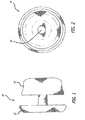
- the cuff 10 is shown in its relaxed, expanded configuration and comprises a generally tubular structure having two flared ends 12 and 13 and a narrow tubular body 14.
- the elongated tube that is used to construct the cuff 10 is formed from at least one braided strand capable of exhibiting super-elasticity or shape memory.
- the elongated tube is folded in half upon itself such that the first end 12 becomes a folded end and the second end 13 includes a plurality of unbraided strands.
- the tubular body is thus two-ply.
- the strand or strands may be fibrous, non-fibrous, multifilament, or monofilament.
- Nitinol is an example of a preferable material for the strand(s).
- the strand(s) are braided to allow the device to be expanded longitudinally into a very long, thin tube capable of being placed in a very small delivery catheter.
- the cuff 10 can be inserted into a delivery catheter that is sized 16 Fr or smaller.
- the braids are tight enough to catch emboli that may be dislodged from a lumen wall, while still allowing the thin, elongated configuration.
- the cuff 10 includes a central lumen 16, which extends through the entire cuff 10.
- the central lumen 16 is sized to receive a delivery catheter for a prosthetic device such as a stent.
- the lumen 16 has ends that flare or mushroom gently, thereby creating a funnel for guiding a delivery catheter into the center of the lumen 16.
- Figures 1 and 2 show that, even when the cuff 10 is in a radially expanded, relaxed configuration, the lumen 16 is small and very well defined.
- the mushroom-like ends 12 and 13 expand and conform to the shape of the target vessel lumen while the cuff lumen 16 remains well defined and relatively centered within the cuff 10.
- the cuff 10 presents an ideal target and guide for a physician placing a prosthetic valve or stent within the cuff.
- the cuff 10 is radiopaque, making the target it presents even more accessible.
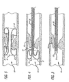
- a cuff 10 is percutaneously delivered to a targeted stenosed valve 18 via a delivery catheter 20.
- the catheter 20 is advanced until a distal end 22 of the catheter is past the targeted valve 18.
- the delivery catheter 20 is then retracted relative to the cuff 10. Doing so releases the distal end 12, which immediately flares outwardly. With the end 12 in contact with the vessel walls, the physician may pull gently on the catheter 20 and the cuff 10 to abut the end 12 of the cuff 10 against the stenosed valve 18, thereby ensuring proper placement of the cuff 10.
- the catheter 20 is retracted fully, allowing the proximal end 13 of the cuff 10 to expand against the vessel walls on a proximal side of the stenosed valve 18.
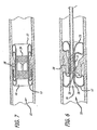
- the stenosed valve 18 is now completely encased in the braided mesh of the cuff 10, and the cuff is ready to receive a prosthetic device such as a stented prosthetic valve 24 ( Figures 6 and 7 ).
- a prosthetic device such as a stented prosthetic valve 24 ( Figures 6 and 7 ).
- the central lumen 16 of the cuff presents a path through the targeted site and provides an ideal receiving seat for the prosthetic valve 24.
- the stented prosthetic valve 26 is percutaneously delivered to the cuff 10 via a catheter 28.
- the catheter 28 is inserted directly into the cuff lumen 16, using the funneled end 13 as a guide.
- the prosthetic valve 26 is expanded and the catheter 28 removed. Expanding the stented prosthetic 26 necessarily expands the central lumen 16. Doing so causes the cuff 10 to shorten and the flared ends 12 and 13 to fold back further, placing a more secure grip on the stenosed valve 18. Furthermore, any plaque or other material dislodged during the expansion of the prosthetic 26 is trapped by the ends 12 and 13.
- the cuff 10 provides an optimal seat for the prosthetic 26 and prevents any blood from leaking around the prosthetic valve 26. Over time, the braided strand(s) promote ingrowth, further improving the seal provided by the cuff 10.
- FIG. 8 shows a cuff 10 having a two-ply body with a material 32 trapped between the two layers.
- the non-woven fabric expands easily such that the expansion characteristics of the cuff 10 are not affected.
- the material 32 may be impregnated with a therapeutic compound.
- the material 32 can consist of a non-woven material, a woven fabric, a polymer or other material.
- FIG. 9 the cuff 10 originally depicted in Figures 1 and 2 is shown with a plug 30 expanding the central lumen 16 of the cuff 10. This demonstrates how the cuff 10 shortens and the ends 12 and 13 fold back when the lumen 16 is expanded. Expanding the central lumen 16 thus causes the ends 12 and 13 to create a strong grip on native tissues, such as valve leaflets, lodged between the ends 12 and 13.
- the ends of the elongate tube roll outwardly toward the middle of the device.
- the end can roll inwardly toward the middle of the device. This action would be facilitated by use of a super-elastic or shape memory material such as Nitinol.
- Preferred examples include:
Abstract
Description
- This application is related to and claims priority benefit of U.S. Provisional Patent Application Serial No.
60/685,433, filed May 27, 2005 60/685,349, filed May 27, 2005 U.S. Provisional Patent Application Serial No. 60/709,595 filed August 18, 2005 - There has been a significant movement toward developing and performing cardiac and other surgeries using a percutaneous approach. Through the use of one or more catheters that are introduced through, for example, the femoral artery, tools and devices can be delivered to a desired area in the cardiovascular system to perform any number or complicated procedures that normally otherwise require an invasive surgical procedure. Such approaches greatly reduce the trauma endured by the patient and can significantly reduce recovery periods. The percutaneous approach is particularly attractive as an alternative to performing open-heart surgery.
- Valve replacement surgery provides one example of an area where percutaneous solutions are being developed. A number of diseases result in a thickening, and subsequent immobility or reduced mobility, of valves leaflets. Valve immobility leads to a narrowing, or stenosis, of the passageway through the valve. The increased resistance to blood flow that a stenosed valve presents eventually leads to heart failure and death.
- Treating severe valve stenosis or regurgitation has heretofore involved complete removal of the existing native valve followed by the implantation of a prosthetic valve. Naturally, this is a heavily invasive procedure and inflicts great trauma on the body leading usually to great discomfort and considerable recovery time. It is also a sophisticated procedure that requires great expertise and talent to perform.
- Historically, such valve replacement surgery has been performed using traditional open-heart surgery where the chest is opened, the heart stopped, the patient placed on cardiopulmonary bypass, the native valve excised and the replacement valve attached. A proposed percutaneous valve replacement alternative method is disclosed in
U.S. Pat. No. 6,168,614 (the entire contents of which are hereby incorporated by reference) issued to Andersen et al. In this patent, the prosthetic valve is collapsed to a size that fits within a catheter. The catheter is then inserted into the patient's vasculature and moved so as to position the collapsed valve at the location of the native valve. A deployment mechanism is activated that expands the replacement valve against the walls of the body lumen. The expansion force pushes the leaflets of the existing native valve against the lumen wall thus essentially "excising" the native valve for all intents and purposes. The expanded structure, which includes a stent configured to have a valve shape with valve leaflet supports, is then released from the catheter and begins to take on the function of the native valve. As a result, a full valve replacement has been achieved but at a significantly reduced physical impact to the patient. - However, this approach has decided shortcomings. One particular drawback with the percutaneous approach disclosed in the Andersen '614 patent is the difficulty in preventing leakage around the perimeter of the new valve after implantation. As the tissue of the native valve remains within the lumen, there is a strong likelihood that the commissural junctions and fusion points of the valve tissue (as pushed against the lumen wall) will make sealing of the prosthetic valve around the interface between the lumen and the prosthetic valve difficult.
- Other drawbacks of the Andersen '614 approach pertain to its reliance on stents as support scaffolding for the prosthetic valve. First, stents can create emboli when they expand. Second, stents are typically not effective at trapping the emboli they dislodge, either during or after deployment. Third, stents do not typically conform to the features of the native lumen in which they are placed, making a prosthetic valve housed within a stent subject to paravalvular leakage. Fourth, stents can be hard to center within a lumen.
- As to the first drawback, stents usually fall into one of two categories: self-expanding stents and expandable stents. Self-expanding stents are compressed when loaded into a catheter and expand to their original, non-compressed size when released from the catheter. Balloon expandable stents are loaded into a catheter in a compressed but relaxed state. A balloon is placed within the stent. Upon deployment, the catheter is retracted and the balloon inflated, thereby expanding the stent to a desired size. Both of these stent types exhibit significant force upon expansion. The force is usually strong enough to crack or pop thrombosis, thereby causing pieces of atherosclerotic plaque to dislodge and become emboli. If the stent is being implanted to treat a stenosed vessel, a certain degree of such expansion is desirable. However, if the stent is merely being implanted to displace native valves, less force may be desirable to reduce the chance of creating emboli.
- As to the second drawback, if emboli are created, expanded stents usually have members that are too spaced apart to be effective to trap any dislodged material. Often, secondary precautions must be taken including the use of nets and irrigation ports.
- The third drawback is due to the relative inflexibility of stents. Stents rely on the elastic nature of the native vessel to conform around the stent. Stents used to open a restricted vessel do not require a seal between the vessel and the stent. However, when using a stent to displace native valves and house a prosthetic valve, a seal between the stent and the vessel is necessary to prevent paravalvular leakage. Due to the non-conforming nature of stents, this seal is hard to achieve, especially when displacing stenosed valve leaflets.
- The fourth drawback is that stents can be hard to center within a lumen. Stenosed valves can have very irregular shapes. When placing a stent within an irregularly shaped, calcified valve, the delivery catheter can become misaligned causing the stent to be delivered to an off-center location, such as between two calcified valve leaflets. Expanding the stent in such a location can result in poor seating against the lumen walls and significant paravalvular leakage or a non-functioning prosthetic valve.
- The present invention addresses the aforementioned drawbacks by providing a tubular or toroidal cuff that surrounds a native valve and creates an ideal implantation site for a stent. The cuff is constructed of at least one fine braided strand of a material having super-elastic or shape memory characteristics, such as Nitinol. The cuff is tubular when in an extended configuration within a delivery catheter. When released from the delivery catheter, the ends of the cuff curl back on themselves, trapping the native valve leaflets between the curled ends. The center of the cuff does not expand as much as the ends, thereby leaving a reduced diameter lumen that is ideal for receiving an intravascular device.
-
-
Figure 1 is a side view of a preferred device of the present invention; -
Figure 2 is an end view of the device ofFigure 1 ; -
Figures 3-7 are cutaway views of a device of the present invention being deployed in a native vessel; -
Figure 8 is a side view of a preferred device of the present invention; -
Figure 9 is an end view of the device ofFigure 1 in an expanded state; and, -
Figure 10 is a side view of the device ofFigure 1 in an expanded state. - Referring now to the Figures and first to
Figures 1 and 2 , there is shown anintravascular cuff 10 of the present invention. Thecuff 10 is shown in its relaxed, expanded configuration and comprises a generally tubular structure having two flared ends 12 and 13 and a narrowtubular body 14. The elongated tube that is used to construct thecuff 10 is formed from at least one braided strand capable of exhibiting super-elasticity or shape memory. In one embodiment, the elongated tube is folded in half upon itself such that thefirst end 12 becomes a folded end and thesecond end 13 includes a plurality of unbraided strands. The tubular body is thus two-ply. The strand or strands may be fibrous, non-fibrous, multifilament, or monofilament. Nitinol is an example of a preferable material for the strand(s). The strand(s) are braided to allow the device to be expanded longitudinally into a very long, thin tube capable of being placed in a very small delivery catheter. Preferably, thecuff 10 can be inserted into a delivery catheter that is sized 16 Fr or smaller. The braids are tight enough to catch emboli that may be dislodged from a lumen wall, while still allowing the thin, elongated configuration. - The
cuff 10 includes acentral lumen 16, which extends through theentire cuff 10. Thecentral lumen 16 is sized to receive a delivery catheter for a prosthetic device such as a stent. Preferably, thelumen 16 has ends that flare or mushroom gently, thereby creating a funnel for guiding a delivery catheter into the center of thelumen 16. -
Figures 1 and 2 show that, even when thecuff 10 is in a radially expanded, relaxed configuration, thelumen 16 is small and very well defined. Thus, when deployed, the mushroom-like ends 12 and 13 expand and conform to the shape of the target vessel lumen while thecuff lumen 16 remains well defined and relatively centered within thecuff 10. Thus, thecuff 10 presents an ideal target and guide for a physician placing a prosthetic valve or stent within the cuff. Preferably, thecuff 10 is radiopaque, making the target it presents even more accessible. - The deployment of the
cuff 10 is illustrated inFigures 3-7 . Beginning withFigure 3 , acuff 10 is percutaneously delivered to a targetedstenosed valve 18 via adelivery catheter 20. Thecatheter 20 is advanced until adistal end 22 of the catheter is past the targetedvalve 18. - As seen in
Figure 4 , thedelivery catheter 20 is then retracted relative to thecuff 10. Doing so releases thedistal end 12, which immediately flares outwardly. With theend 12 in contact with the vessel walls, the physician may pull gently on thecatheter 20 and thecuff 10 to abut theend 12 of thecuff 10 against thestenosed valve 18, thereby ensuring proper placement of thecuff 10. - Next, as shown in
Figure 5 , thecatheter 20 is retracted fully, allowing theproximal end 13 of thecuff 10 to expand against the vessel walls on a proximal side of thestenosed valve 18. Thestenosed valve 18 is now completely encased in the braided mesh of thecuff 10, and the cuff is ready to receive a prosthetic device such as a stented prosthetic valve 24 (Figures 6 and 7 ). Notably, despite the irregular shape of thestenosed valve 18, thecentral lumen 16 of the cuff presents a path through the targeted site and provides an ideal receiving seat for the prosthetic valve 24. - In
Figure 6 , the stentedprosthetic valve 26 is percutaneously delivered to thecuff 10 via acatheter 28. Thecatheter 28 is inserted directly into thecuff lumen 16, using the funneledend 13 as a guide. - In
Figure 7 , theprosthetic valve 26 is expanded and thecatheter 28 removed. Expanding the stented prosthetic 26 necessarily expands thecentral lumen 16. Doing so causes thecuff 10 to shorten and the flared ends 12 and 13 to fold back further, placing a more secure grip on thestenosed valve 18. Furthermore, any plaque or other material dislodged during the expansion of the prosthetic 26 is trapped by theends cuff 10 provides an optimal seat for the prosthetic 26 and prevents any blood from leaking around theprosthetic valve 26. Over time, the braided strand(s) promote ingrowth, further improving the seal provided by thecuff 10. - One embodiment of the present invention uses a non-woven fabric to further enhance the seal created between the
cuff 10 and the vessel walls.Figure 8 shows acuff 10 having a two-ply body with a material 32 trapped between the two layers. The non-woven fabric expands easily such that the expansion characteristics of thecuff 10 are not affected. Additionally, thematerial 32 may be impregnated with a therapeutic compound. The material 32 can consist of a non-woven material, a woven fabric, a polymer or other material. - Referring now to
Figures 9 and 10 , thecuff 10 originally depicted inFigures 1 and 2 is shown with aplug 30 expanding thecentral lumen 16 of thecuff 10. This demonstrates how thecuff 10 shortens and theends lumen 16 is expanded. Expanding thecentral lumen 16 thus causes theends ends - In another embodiment, on deployment from a catheter, the ends of the elongate tube roll outwardly toward the middle of the device. Alternatively, the end can roll inwardly toward the middle of the device. This action would be facilitated by use of a super-elastic or shape memory material such as Nitinol.
- Although the invention has been described in terms of particular embodiments and applications, one of ordinary skill in the art, in light of this teaching, can generate additional embodiments and modifications without departing from the spirit of or exceeding the scope of the claimed invention. Accordingly, it is to be understood that the drawings and descriptions herein are proffered by way of example to facilitate comprehension of the invention and should not be construed to limit the scope thereof.
- Preferred examples include:
- 1. An intravascular cuff for receiving a prosthetic, comprising:
- at least one strand braided to form a tubular structure having an extended configuration and a deployed configuration;
- whereby in the extended configuration, the tubular structure includes:
- a first end and a second end;
- a tubular body between the first end and the second end;
- a lumen extending through the body;
- whereby in the deployed configuration, the first and second ends assume an expanded shape relative to the tubular body.
- 2. The intravascular cuff for receiving a prosthetic of example 1 wherein said at least one strand comprises a shape memory material.
- 3. The intravascular cuff for receiving a prosthetic of example 1 wherein said at least one strand comprises a super-elastic material.
- 4. The intravascular cuff for receiving a prosthetic of example 2 wherein said at least one strand comprises Nitinol.
- 5. The intravascular cuff for receiving a prosthetic of example 1 wherein said tubular body between the first end and the second end comprises a two-ply body.
- 6. The intravascular cuff for receiving a prosthetic of example 1 wherein said tubular body between the first end and the second end comprises a two-ply body, formed by inverting said tubular body within itself to create a folded end and an unbraided end.
- 7. The intravascular cuff for receiving a prosthetic of example 5 further comprising a material sandwiched between said first and second ply.
- 8. The material of example 7 wherein said material is selected from the group consisting of non-woven material, woven material, braided fabric and polymer.
- 9. The intravascular cuff for receiving a prosthetic of example 1 wherein the expanded shape of the ends comprises a mushroom shape.
- 10. The intravascular cuff for receiving a prosthetic of example 1 wherein the lumen includes funneled ends in the deployed configuration.
- 11. The intravascular cuff for receiving a prosthetic of example 1 wherein the tubular body between the first end and the second end retains a relatively unexpanded state in the deployed configuration.
- 12. The intravascular cuff for receiving a prosthetic of example 1 wherein the tubular body shortens when expanded from the deployed state.
- 13. A method of preventing leakage between a prosthetic valve and a vessel wall comprising:
- deploying a self-expanding cuff in the vessel prior to implanting the prosthetic valve;
- implanting the prosthetic valve within a lumen of the cuff.
- 14. The method of example 13 further comprising expanding the prosthetic valve within the lumen of the cuff.
- 15. The method of example 14 wherein expanding the prosthetic valve within the lumen of the cuff causes the body portion of the cuff to expand.
- 16. The method of example 15 wherein causing the body portion to expand further comprises causing the body portion to shorten longitudinally.
- 17. An intravascular cuff comprising:
- at least one strand braided to form a tubular device having a lumen extending therethrough, the device having elongated, relaxed, and expanded configurations;
- whereby in the elongated configuration, the tubular device is capable of insertion into a catheter;
- whereby in the relaxed configuration, the tubular device has a first end and a second end having diameters greater than that of a body portion between the first and second ends;
- whereby in the expanded configuration, the tubular device has a length shorter than a length of the device in the relaxed configuration.
- 18. The intravascular cuff of example 17 wherein said at least one strand comprises Nitinol.
- 19. The intravascular cuff of example 17 wherein said tubular device comprises a two-ply body.
- 20. The intravascular cuff for receiving a prosthetic of example 17 wherein said tubular body between the first end and the second end comprises a two-ply body, formed by inverting said tubular body within itself to create a folded end and an unbraided end.
- 21. The intravascular cuff of example 19 further comprising a material disposed between the two plies.
- 22. The intravascular cuff of example 21 wherein said material comprises a fabric.
- 23. The intravascular cuff of example 17 wherein at least one of the ends folds back on itself in the relaxed configuration in order to achieve said greater diameter.
- 24. The intravascular cuff of example 17 wherein said lumen is flared outwardly proximate the first and second ends in the relaxed configuration.
Claims (20)
- An intravascular cuff (10) for receiving a prosthetic valve in situ, comprising:a two-ply braided tubular structure (14) defining a lumen and having an extended configuration and a deployed configuration;a material (32) sandwiched between the plies of the two-ply braided tubular structure;whereby when said two-ply braided tubular structure is released from a delivery catheter, ends of said two-ply braided tubular structure fold back on themselves to conform to the shape of a target vessel and create gaps between the two plies while said lumen remains well-defined and centered within said intravascular cuff;whereby in said deployed configuration, said material prevents blood from flowing through said plies of said two-ply braided tubular structure.
- The intravascular cuff for receiving a prosthetic valve of claim 1 wherein said two-ply braided tubular structure is comprised of at least one strand of shape memory metal.
- The intravascular cuff for receiving a prosthetic valve of claim 1 wherein said two-ply braided tubular structure is comprised of at least one strand of super-elastic material.
- The intravascular cuff for receiving a prosthetic valve of claim 2 wherein said at least one strand comprises Nitinol.
- The intravascular cuff for receiving a prosthetic valve of claim 1 wherein said two-ply braided tubular structure is formed by inverting said tubular structure within itself to create at least one folded end.
- The intravascular cuff of claim 1 wherein said material is selected from the group consisting of non-woven material, woven material, braided fabric and polymer.
- The intravascular cuff for receiving a prosthetic valve of claim 1 wherein the lumen includes funneled ends in the deployed configuration.
- The intravascular cuff for receiving a prosthetic valve of claim 1 wherein the tubular structure between the first end and the second end retains a relatively unexpanded state in the deployed configuration.
- The intravascular cuff for receiving a prosthetic valve of claim 1 wherein the tubular structure shortens when expanded from the deployed state.
- The intravascular cuff of claim 1 wherein said lumen is flared outwardly proximate the first and second ends in the deployed configuration.
- An intravascular cuff (10) for receiving a prosthetic valve in situ, comprising:a two-ply braided tubular structure (14) defining a lumen and having an extended configuration and a deployed configuration;whereby when said two-ply braided tubular structure is released from a delivery catheter, ends of said two-ply braided tubular structure expand to create gaps between the two plies while said lumen remains well-defined and centered within said intravascular cuff;whereby said gaps in said ends create funneled ends in said lumen for guiding a delivery device for a prosthetic valve into said lumen.
- The intravascular cuff for receiving a prosthetic valve of claim 11 wherein said two-ply braided tubular structure is comprised of at least one strand of shape memory metal.
- The intravascular cuff for receiving a prosthetic valve of claim 11 wherein said two-ply braided tubular structure is comprised of at least one strand of super-elastic material.
- The intravascular cuff for receiving a prosthetic valve of claim 12 wherein said at least one strand comprises Nitinol.
- The intravascular cuff for receiving a prosthetic valve of claim 11 wherein said two-ply braided tubular structure is formed by inverting said tubular structure within itself to create at least one folded end.
- The intravascular cuff for receiving a prosthetic valve of claim 11 further comprising material trapped between plies of said two-ply braided tubular structure.
- The intravascular cuff of claim 17 wherein said material is selected from the group consisting of non-woven material, woven material, braided fabric and polymer.
- The intravascular cuff for receiving a prosthetic valve of claim 11 wherein the tubular structure between the first end and the second end retains a relatively unexpanded state in the deployed configuration.
- The intravascular cuff for receiving a prosthetic valve of claim 11 wherein the tubular structure shortens when expanded from the deployed state.
- The intravascular cuff of claim 11 wherein said lumen is flared outwardly proximate the first and second ends in the deployed configuration.
Priority Applications (1)
| Application Number | Priority Date | Filing Date | Title |
|---|---|---|---|
| EP16198110.5A EP3146938A1 (en) | 2005-05-27 | 2006-05-30 | Intravascular cuff |
Applications Claiming Priority (2)
| Application Number | Priority Date | Filing Date | Title |
|---|---|---|---|
| US68543305P | 2005-05-27 | 2005-05-27 | |
| EP06760564.2A EP1954212B1 (en) | 2005-05-27 | 2006-05-30 | Intravascular cuff |
Related Parent Applications (1)
| Application Number | Title | Priority Date | Filing Date |
|---|---|---|---|
| EP06760564.2A Division EP1954212B1 (en) | 2005-05-27 | 2006-05-30 | Intravascular cuff |
Related Child Applications (2)
| Application Number | Title | Priority Date | Filing Date |
|---|---|---|---|
| EP16198110.5A Division EP3146938A1 (en) | 2005-05-27 | 2006-05-30 | Intravascular cuff |
| EP16198110.5A Division-Into EP3146938A1 (en) | 2005-05-27 | 2006-05-30 | Intravascular cuff |
Publications (2)
| Publication Number | Publication Date |
|---|---|
| EP3005979A1 true EP3005979A1 (en) | 2016-04-13 |
| EP3005979B1 EP3005979B1 (en) | 2018-03-28 |
Family
ID=37453005
Family Applications (3)
| Application Number | Title | Priority Date | Filing Date |
|---|---|---|---|
| EP06760564.2A Not-in-force EP1954212B1 (en) | 2005-05-27 | 2006-05-30 | Intravascular cuff |
| EP15196906.0A Not-in-force EP3005979B1 (en) | 2005-05-27 | 2006-05-30 | Intravascular cuff |
| EP16198110.5A Withdrawn EP3146938A1 (en) | 2005-05-27 | 2006-05-30 | Intravascular cuff |
Family Applications Before (1)
| Application Number | Title | Priority Date | Filing Date |
|---|---|---|---|
| EP06760564.2A Not-in-force EP1954212B1 (en) | 2005-05-27 | 2006-05-30 | Intravascular cuff |
Family Applications After (1)
| Application Number | Title | Priority Date | Filing Date |
|---|---|---|---|
| EP16198110.5A Withdrawn EP3146938A1 (en) | 2005-05-27 | 2006-05-30 | Intravascular cuff |
Country Status (7)
| Country | Link |
|---|---|
| US (5) | US8663312B2 (en) |
| EP (3) | EP1954212B1 (en) |
| JP (1) | JP5111365B2 (en) |
| CN (2) | CN103584929B (en) |
| AU (3) | AU2006251990B2 (en) |
| CA (1) | CA2614492C (en) |
| WO (1) | WO2006128185A2 (en) |
Families Citing this family (231)
| Publication number | Priority date | Publication date | Assignee | Title |
|---|---|---|---|---|
| US6006134A (en) | 1998-04-30 | 1999-12-21 | Medtronic, Inc. | Method and device for electronically controlling the beating of a heart using venous electrical stimulation of nerve fibers |
| US7018406B2 (en) | 1999-11-17 | 2006-03-28 | Corevalve Sa | Prosthetic valve for transluminal delivery |
| US8016877B2 (en) | 1999-11-17 | 2011-09-13 | Medtronic Corevalve Llc | Prosthetic valve for transluminal delivery |
| US8579966B2 (en) | 1999-11-17 | 2013-11-12 | Medtronic Corevalve Llc | Prosthetic valve for transluminal delivery |
| US8241274B2 (en) | 2000-01-19 | 2012-08-14 | Medtronic, Inc. | Method for guiding a medical device |
| US7749245B2 (en) | 2000-01-27 | 2010-07-06 | Medtronic, Inc. | Cardiac valve procedure methods and devices |
| US6692513B2 (en) | 2000-06-30 | 2004-02-17 | Viacor, Inc. | Intravascular filter with debris entrapment mechanism |
| US7544206B2 (en) | 2001-06-29 | 2009-06-09 | Medtronic, Inc. | Method and apparatus for resecting and replacing an aortic valve |
| US8771302B2 (en) | 2001-06-29 | 2014-07-08 | Medtronic, Inc. | Method and apparatus for resecting and replacing an aortic valve |
| US8623077B2 (en) | 2001-06-29 | 2014-01-07 | Medtronic, Inc. | Apparatus for replacing a cardiac valve |
| FR2826863B1 (en) | 2001-07-04 | 2003-09-26 | Jacques Seguin | ASSEMBLY FOR PLACING A PROSTHETIC VALVE IN A BODY CONDUIT |
| FR2828091B1 (en) | 2001-07-31 | 2003-11-21 | Seguin Jacques | ASSEMBLY ALLOWING THE PLACEMENT OF A PROTHETIC VALVE IN A BODY DUCT |
| US7097659B2 (en) | 2001-09-07 | 2006-08-29 | Medtronic, Inc. | Fixation band for affixing a prosthetic heart valve to tissue |
| US9579194B2 (en) | 2003-10-06 | 2017-02-28 | Medtronic ATS Medical, Inc. | Anchoring structure with concave landing zone |
| ITTO20040135A1 (en) | 2004-03-03 | 2004-06-03 | Sorin Biomedica Cardio Spa | CARDIAC VALVE PROSTHESIS |
| US7686825B2 (en) | 2004-03-25 | 2010-03-30 | Hauser David L | Vascular filter device |
| US20060025857A1 (en) | 2004-04-23 | 2006-02-02 | Bjarne Bergheim | Implantable prosthetic valve |
| US7445630B2 (en) | 2004-05-05 | 2008-11-04 | Direct Flow Medical, Inc. | Method of in situ formation of translumenally deployable heart valve support |
| DE102005003632A1 (en) | 2005-01-20 | 2006-08-17 | Fraunhofer-Gesellschaft zur Förderung der angewandten Forschung e.V. | Catheter for the transvascular implantation of heart valve prostheses |
| ITTO20050074A1 (en) | 2005-02-10 | 2006-08-11 | Sorin Biomedica Cardio Srl | CARDIAC VALVE PROSTHESIS |
| US20100312333A1 (en) * | 2009-04-29 | 2010-12-09 | The Cleveland Clinic Foundation | Apparatus and method for replacing a diseased cardiac valve |
| US7914569B2 (en) | 2005-05-13 | 2011-03-29 | Medtronics Corevalve Llc | Heart valve prosthesis and methods of manufacture and use |
| US8663312B2 (en) * | 2005-05-27 | 2014-03-04 | Hlt, Inc. | Intravascular cuff |
| AU2006251938B2 (en) | 2005-05-27 | 2011-09-29 | Hlt, Inc. | Stentless support structure |
| EP1887983A4 (en) | 2005-06-07 | 2008-12-17 | Direct Flow Medical Inc | Stentless aortic valve replacement with high radial strength |
| WO2007038540A1 (en) | 2005-09-26 | 2007-04-05 | Medtronic, Inc. | Prosthetic cardiac and venous valves |
| US8075615B2 (en) | 2006-03-28 | 2011-12-13 | Medtronic, Inc. | Prosthetic cardiac valve formed from pericardium material and methods of making same |
| US8834564B2 (en) | 2006-09-19 | 2014-09-16 | Medtronic, Inc. | Sinus-engaging valve fixation member |
| US8348995B2 (en) | 2006-09-19 | 2013-01-08 | Medtronic Ventor Technologies, Ltd. | Axial-force fixation member for valve |
| US11304800B2 (en) | 2006-09-19 | 2022-04-19 | Medtronic Ventor Technologies Ltd. | Sinus-engaging valve fixation member |
| EP2083901B1 (en) | 2006-10-16 | 2017-12-27 | Medtronic Ventor Technologies Ltd. | Transapical delivery system with ventriculo-arterial overflow bypass |
| US8133213B2 (en) | 2006-10-19 | 2012-03-13 | Direct Flow Medical, Inc. | Catheter guidance through a calcified aortic valve |
| US7935144B2 (en) | 2006-10-19 | 2011-05-03 | Direct Flow Medical, Inc. | Profile reduction of valve implant |
| CN101641061B (en) | 2006-12-06 | 2013-12-18 | 美顿力科尔瓦有限责任公司 | System and method for transapical delivery of annulus anchored self-expanding valve |
| WO2008100599A1 (en) * | 2007-02-15 | 2008-08-21 | Medtronic, Inc. | Multi-layered stents and methods of implanting |
| EP2129333B1 (en) | 2007-02-16 | 2019-04-03 | Medtronic, Inc | Replacement prosthetic heart valves |
| US9138315B2 (en) * | 2007-04-13 | 2015-09-22 | Jenavalve Technology Gmbh | Medical device for treating a heart valve insufficiency or stenosis |
| US7896915B2 (en) | 2007-04-13 | 2011-03-01 | Jenavalve Technology, Inc. | Medical device for treating a heart valve insufficiency |
| FR2915087B1 (en) | 2007-04-20 | 2021-11-26 | Corevalve Inc | IMPLANT FOR TREATMENT OF A HEART VALVE, IN PARTICULAR OF A MITRAL VALVE, EQUIPMENT INCLUDING THIS IMPLANT AND MATERIAL FOR PLACING THIS IMPLANT. |
| EP3150171A1 (en) | 2007-05-15 | 2017-04-05 | JenaValve Technology, Inc. | Handle for manipulating a catheter tip, catheter system and medical insertion system for inserting a self-expandalbe heart valve stent |
| FR2916627B1 (en) * | 2007-05-30 | 2010-09-17 | Perouse Lab | NECESSARY FOR TREATING A BLOOD CIRCULATION CONDUIT |
| DE102007031146A1 (en) * | 2007-06-27 | 2009-01-08 | Aesculap Ag | Sinus patches to replace defective sinus at the aortic root |
| US8747458B2 (en) | 2007-08-20 | 2014-06-10 | Medtronic Ventor Technologies Ltd. | Stent loading tool and method for use thereof |
| CA2697364C (en) | 2007-08-23 | 2017-10-17 | Direct Flow Medical, Inc. | Translumenally implantable heart valve with formed in place support |
| DE102007043830A1 (en) | 2007-09-13 | 2009-04-02 | Lozonschi, Lucian, Madison | Heart valve stent |
| AU2008305600B2 (en) | 2007-09-26 | 2013-07-04 | St. Jude Medical, Inc. | Collapsible prosthetic heart valves |
| US9532868B2 (en) | 2007-09-28 | 2017-01-03 | St. Jude Medical, Inc. | Collapsible-expandable prosthetic heart valves with structures for clamping native tissue |
| US10856970B2 (en) | 2007-10-10 | 2020-12-08 | Medtronic Ventor Technologies Ltd. | Prosthetic heart valve for transfemoral delivery |
| US9848981B2 (en) | 2007-10-12 | 2017-12-26 | Mayo Foundation For Medical Education And Research | Expandable valve prosthesis with sealing mechanism |
| US8157852B2 (en) | 2008-01-24 | 2012-04-17 | Medtronic, Inc. | Delivery systems and methods of implantation for prosthetic heart valves |
| WO2009094197A1 (en) | 2008-01-24 | 2009-07-30 | Medtronic, Inc. | Stents for prosthetic heart valves |
| US9149358B2 (en) | 2008-01-24 | 2015-10-06 | Medtronic, Inc. | Delivery systems for prosthetic heart valves |
| EP2254512B1 (en) | 2008-01-24 | 2016-01-06 | Medtronic, Inc. | Markers for prosthetic heart valves |
| US9393115B2 (en) | 2008-01-24 | 2016-07-19 | Medtronic, Inc. | Delivery systems and methods of implantation for prosthetic heart valves |
| EP3744291B1 (en) | 2008-01-24 | 2022-11-23 | Medtronic, Inc. | Stents for prosthetic heart valves |
| US9044318B2 (en) | 2008-02-26 | 2015-06-02 | Jenavalve Technology Gmbh | Stent for the positioning and anchoring of a valvular prosthesis |
| BR112012021347A2 (en) | 2008-02-26 | 2019-09-24 | Jenavalve Tecnology Inc | stent for positioning and anchoring a valve prosthesis at an implantation site in a patient's heart |
| WO2009108355A1 (en) | 2008-02-28 | 2009-09-03 | Medtronic, Inc. | Prosthetic heart valve systems |
| US8313525B2 (en) | 2008-03-18 | 2012-11-20 | Medtronic Ventor Technologies, Ltd. | Valve suturing and implantation procedures |
| US8430927B2 (en) | 2008-04-08 | 2013-04-30 | Medtronic, Inc. | Multiple orifice implantable heart valve and methods of implantation |
| US8312825B2 (en) | 2008-04-23 | 2012-11-20 | Medtronic, Inc. | Methods and apparatuses for assembly of a pericardial prosthetic heart valve |
| US8696743B2 (en) | 2008-04-23 | 2014-04-15 | Medtronic, Inc. | Tissue attachment devices and methods for prosthetic heart valves |
| EP2119417B2 (en) | 2008-05-16 | 2020-04-29 | Sorin Group Italia S.r.l. | Atraumatic prosthetic heart valve prosthesis |
| ES2584315T3 (en) | 2008-07-15 | 2016-09-27 | St. Jude Medical, Inc. | Collapsible and re-expandable prosthetic heart valve sleeve designs and complementary technological applications |
| US9351715B2 (en) * | 2008-07-24 | 2016-05-31 | St. Jude Medical, Cardiology Division, Inc. | Multi-layered medical device for treating a target site and associated method |
| US9232992B2 (en) * | 2008-07-24 | 2016-01-12 | Aga Medical Corporation | Multi-layered medical device for treating a target site and associated method |
| EP4018967A1 (en) | 2008-09-15 | 2022-06-29 | Medtronic Ventor Technologies Ltd | Prosthetic heart valve having identifiers for aiding in radiographic positioning |
| US8721714B2 (en) | 2008-09-17 | 2014-05-13 | Medtronic Corevalve Llc | Delivery system for deployment of medical devices |
| US8690936B2 (en) | 2008-10-10 | 2014-04-08 | Edwards Lifesciences Corporation | Expandable sheath for introducing an endovascular delivery device into a body |
| US8137398B2 (en) | 2008-10-13 | 2012-03-20 | Medtronic Ventor Technologies Ltd | Prosthetic valve having tapered tip when compressed for delivery |
| US8986361B2 (en) * | 2008-10-17 | 2015-03-24 | Medtronic Corevalve, Inc. | Delivery system for deployment of medical devices |
| US8834563B2 (en) | 2008-12-23 | 2014-09-16 | Sorin Group Italia S.R.L. | Expandable prosthetic valve having anchoring appendages |
| JP5659168B2 (en) | 2009-02-27 | 2015-01-28 | セント・ジュード・メディカル,インコーポレイテッド | Foldable prosthetic heart valve stent features |
| EP2246011B1 (en) | 2009-04-27 | 2014-09-03 | Sorin Group Italia S.r.l. | Prosthetic vascular conduit |
| US8808369B2 (en) | 2009-10-05 | 2014-08-19 | Mayo Foundation For Medical Education And Research | Minimally invasive aortic valve replacement |
| US8449599B2 (en) | 2009-12-04 | 2013-05-28 | Edwards Lifesciences Corporation | Prosthetic valve for replacing mitral valve |
| EP3838223A1 (en) | 2009-12-08 | 2021-06-23 | Avalon Medical Ltd. | Device and system for transcatheter mitral valve replacement |
| US9226826B2 (en) | 2010-02-24 | 2016-01-05 | Medtronic, Inc. | Transcatheter valve structure and methods for valve delivery |
| ES2761298T3 (en) | 2010-03-05 | 2020-05-19 | Edwards Lifesciences Corp | Retention mechanisms for prosthetic valves |
| EP3527173A3 (en) * | 2010-03-26 | 2019-12-11 | Thubrikar Aortic Valve Inc. | Valve component, frame component and prosthetic valve device including the same for implantation in a body lumen |
| US8652204B2 (en) | 2010-04-01 | 2014-02-18 | Medtronic, Inc. | Transcatheter valve with torsion spring fixation and related systems and methods |
| US8579964B2 (en) | 2010-05-05 | 2013-11-12 | Neovasc Inc. | Transcatheter mitral valve prosthesis |
| CN103124537B (en) | 2010-05-10 | 2015-08-26 | 心叶科技公司 | Without rack supporting structure |
| US10856978B2 (en) | 2010-05-20 | 2020-12-08 | Jenavalve Technology, Inc. | Catheter system |
| IT1400327B1 (en) | 2010-05-21 | 2013-05-24 | Sorin Biomedica Cardio Srl | SUPPORT DEVICE FOR VALVULAR PROSTHESIS AND CORRESPONDING CORRESPONDENT. |
| BR112012029896A2 (en) | 2010-05-25 | 2017-06-20 | Jenavalve Tech Inc | prosthetic heart valve for stent graft and stent graft |
| US20110307056A1 (en) * | 2010-06-09 | 2011-12-15 | Biotronik Ag | Medical valve implant for implantation in an animal body and/or human body |
| EP2590595B1 (en) | 2010-07-09 | 2015-08-26 | Highlife SAS | Transcatheter atrio-ventricular valve prosthesis |
| WO2012030598A2 (en) | 2010-09-01 | 2012-03-08 | Medtronic Vascular Galway Limited | Prosthetic valve support structure |
| EP2486894B1 (en) | 2011-02-14 | 2021-06-09 | Sorin Group Italia S.r.l. | Sutureless anchoring device for cardiac valve prostheses |
| ES2641902T3 (en) | 2011-02-14 | 2017-11-14 | Sorin Group Italia S.R.L. | Sutureless anchoring device for cardiac valve prostheses |
| US9554897B2 (en) | 2011-04-28 | 2017-01-31 | Neovasc Tiara Inc. | Methods and apparatus for engaging a valve prosthesis with tissue |
| US9308087B2 (en) | 2011-04-28 | 2016-04-12 | Neovasc Tiara Inc. | Sequentially deployed transcatheter mitral valve prosthesis |
| US10285798B2 (en) | 2011-06-03 | 2019-05-14 | Merit Medical Systems, Inc. | Esophageal stent |
| CA3040390C (en) | 2011-08-11 | 2022-03-15 | Tendyne Holdings, Inc. | Improvements for prosthetic valves and related inventions |
| US8986368B2 (en) | 2011-10-31 | 2015-03-24 | Merit Medical Systems, Inc. | Esophageal stent with valve |
| US9827092B2 (en) | 2011-12-16 | 2017-11-28 | Tendyne Holdings, Inc. | Tethers for prosthetic mitral valve |
| EP2609893B1 (en) | 2011-12-29 | 2014-09-03 | Sorin Group Italia S.r.l. | A kit for implanting prosthetic vascular conduits |
| FR2985659B1 (en) | 2012-01-13 | 2015-03-06 | Assist Publ Hopitaux De Paris | DEVICE FOR ANCHORING A PROTHETIC CARDIAC VALVE. |
| US9345573B2 (en) | 2012-05-30 | 2016-05-24 | Neovasc Tiara Inc. | Methods and apparatus for loading a prosthesis onto a delivery system |
| WO2013184630A1 (en) | 2012-06-05 | 2013-12-12 | Merit Medical Systems, Inc. | Esophageal stent |
| WO2014022124A1 (en) | 2012-07-28 | 2014-02-06 | Tendyne Holdings, Inc. | Improved multi-component designs for heart valve retrieval device, sealing structures and stent assembly |
| US9675454B2 (en) | 2012-07-30 | 2017-06-13 | Tendyne Holdings, Inc. | Delivery systems and methods for transcatheter prosthetic valves |
| DE102012107465A1 (en) * | 2012-08-15 | 2014-05-22 | Pfm Medical Ag | Implantable device for use in the human and / or animal body for replacement of an organ flap |
| US9510946B2 (en) | 2012-09-06 | 2016-12-06 | Edwards Lifesciences Corporation | Heart valve sealing devices |
| US8784434B2 (en) | 2012-11-20 | 2014-07-22 | Inceptus Medical, Inc. | Methods and apparatus for treating embolism |
| US9439763B2 (en) | 2013-02-04 | 2016-09-13 | Edwards Lifesciences Corporation | Prosthetic valve for replacing mitral valve |
| CA2891225C (en) * | 2013-03-05 | 2021-03-02 | Merit Medical Systems, Inc. | Reinforced valve |
| WO2014143126A1 (en) | 2013-03-12 | 2014-09-18 | St. Jude Medical, Cardiology Division, Inc. | Self-actuating sealing portions for paravalvular leak protection |
| US9339274B2 (en) | 2013-03-12 | 2016-05-17 | St. Jude Medical, Cardiology Division, Inc. | Paravalvular leak occlusion device for self-expanding heart valves |
| US10271949B2 (en) | 2013-03-12 | 2019-04-30 | St. Jude Medical, Cardiology Division, Inc. | Paravalvular leak occlusion device for self-expanding heart valves |
| US9398951B2 (en) | 2013-03-12 | 2016-07-26 | St. Jude Medical, Cardiology Division, Inc. | Self-actuating sealing portions for paravalvular leak protection |
| US9326856B2 (en) | 2013-03-14 | 2016-05-03 | St. Jude Medical, Cardiology Division, Inc. | Cuff configurations for prosthetic heart valve |
| AU2014227955A1 (en) | 2013-03-15 | 2015-11-12 | Hlt, Inc. | Low-profile prosthetic valve structure |
| JP2016515008A (en) | 2013-03-15 | 2016-05-26 | メリット・メディカル・システムズ・インコーポレーテッド | Esophageal stent |
| US9486306B2 (en) | 2013-04-02 | 2016-11-08 | Tendyne Holdings, Inc. | Inflatable annular sealing device for prosthetic mitral valve |
| US11224510B2 (en) | 2013-04-02 | 2022-01-18 | Tendyne Holdings, Inc. | Prosthetic heart valve and systems and methods for delivering the same |
| US10463489B2 (en) | 2013-04-02 | 2019-11-05 | Tendyne Holdings, Inc. | Prosthetic heart valve and systems and methods for delivering the same |
| US9572665B2 (en) | 2013-04-04 | 2017-02-21 | Neovasc Tiara Inc. | Methods and apparatus for delivering a prosthetic valve to a beating heart |
| US10478293B2 (en) | 2013-04-04 | 2019-11-19 | Tendyne Holdings, Inc. | Retrieval and repositioning system for prosthetic heart valve |
| WO2014179763A1 (en) | 2013-05-03 | 2014-11-06 | Medtronic Inc. | Valve delivery tool |
| US9610159B2 (en) | 2013-05-30 | 2017-04-04 | Tendyne Holdings, Inc. | Structural members for prosthetic mitral valves |
| US10321991B2 (en) | 2013-06-19 | 2019-06-18 | St. Jude Medical, Cardiology Division, Inc. | Collapsible valve having paravalvular leak protection |
| WO2014210124A1 (en) | 2013-06-25 | 2014-12-31 | Mark Christianson | Thrombus management and structural compliance features for prosthetic heart valves |
| JP6465883B2 (en) | 2013-08-01 | 2019-02-06 | テンダイン ホールディングス,インコーポレイテッド | Epicardial anchor device and method |
| JP6563394B2 (en) | 2013-08-30 | 2019-08-21 | イェーナヴァルヴ テクノロジー インコーポレイテッド | Radially foldable frame for an artificial valve and method for manufacturing the frame |
| US10195028B2 (en) | 2013-09-10 | 2019-02-05 | Edwards Lifesciences Corporation | Magnetic retaining mechanisms for prosthetic valves |
| US10117742B2 (en) | 2013-09-12 | 2018-11-06 | St. Jude Medical, Cardiology Division, Inc. | Stent designs for prosthetic heart valves |
| WO2015058039A1 (en) | 2013-10-17 | 2015-04-23 | Robert Vidlund | Apparatus and methods for alignment and deployment of intracardiac devices |
| US10238406B2 (en) | 2013-10-21 | 2019-03-26 | Inari Medical, Inc. | Methods and apparatus for treating embolism |
| ES2773255T3 (en) | 2013-10-28 | 2020-07-10 | Tendyne Holdings Inc | Prosthetic heart valve and systems to supply it |
| US9526611B2 (en) | 2013-10-29 | 2016-12-27 | Tendyne Holdings, Inc. | Apparatus and methods for delivery of transcatheter prosthetic valves |
| EP2870946B1 (en) | 2013-11-06 | 2018-10-31 | St. Jude Medical, Cardiology Division, Inc. | Paravalvular leak sealing mechanism |
| US9700409B2 (en) | 2013-11-06 | 2017-07-11 | St. Jude Medical, Cardiology Division, Inc. | Reduced profile prosthetic heart valve |
| US9913715B2 (en) | 2013-11-06 | 2018-03-13 | St. Jude Medical, Cardiology Division, Inc. | Paravalvular leak sealing mechanism |
| EP3071149B1 (en) | 2013-11-19 | 2022-06-01 | St. Jude Medical, Cardiology Division, Inc. | Sealing structures for paravalvular leak protection |
| EP2896387A1 (en) | 2014-01-20 | 2015-07-22 | Mitricares | Heart valve anchoring device |
| US20150209141A1 (en) | 2014-01-24 | 2015-07-30 | St. Jude Medical, Cardiology Division, Inc. | Stationary intra-annular halo designs for paravalvular leak (pvl) reduction-passive channel filling cuff designs |
| US9820852B2 (en) | 2014-01-24 | 2017-11-21 | St. Jude Medical, Cardiology Division, Inc. | Stationary intra-annular halo designs for paravalvular leak (PVL) reduction—active channel filling cuff designs |
| WO2015120122A2 (en) | 2014-02-05 | 2015-08-13 | Robert Vidlund | Apparatus and methods for transfemoral delivery of prosthetic mitral valve |
| WO2016112085A2 (en) | 2015-01-07 | 2016-07-14 | Mark Christianson | Prosthetic mitral valves and apparatus and methods for delivery of same |
| US9986993B2 (en) | 2014-02-11 | 2018-06-05 | Tendyne Holdings, Inc. | Adjustable tether and epicardial pad system for prosthetic heart valve |
| EP3107496B1 (en) | 2014-02-18 | 2018-07-04 | St. Jude Medical, Cardiology Division, Inc. | Bowed runners for paravalvular leak protection |
| CN106068109B (en) | 2014-03-10 | 2019-07-23 | 坦迪尼控股股份有限公司 | Device and method for positioning and monitoring the tether load of prosthetic mitral valve |
| CR20160424A (en) | 2014-03-26 | 2016-12-08 | St Jude Medical Cardiology Div Inc | Transcather mitral valve stent frames |
| WO2015152980A1 (en) | 2014-03-31 | 2015-10-08 | St. Jude Medical, Cardiology Division, Inc. | Paravalvular sealing via extended cuff mechanisms |
| US10195025B2 (en) | 2014-05-12 | 2019-02-05 | Edwards Lifesciences Corporation | Prosthetic heart valve |
| ES2795358T3 (en) | 2014-05-16 | 2020-11-23 | St Jude Medical Cardiology Div Inc | Subannular sealing for paravalvular leak protection |
| EP3142605A1 (en) | 2014-05-16 | 2017-03-22 | St. Jude Medical, Cardiology Division, Inc. | Stent assembly for use in prosthetic heart valves |
| US9668858B2 (en) | 2014-05-16 | 2017-06-06 | St. Jude Medical, Cardiology Division, Inc. | Transcatheter valve with paravalvular leak sealing ring |
| US9532870B2 (en) * | 2014-06-06 | 2017-01-03 | Edwards Lifesciences Corporation | Prosthetic valve for replacing a mitral valve |
| US10195026B2 (en) | 2014-07-22 | 2019-02-05 | Edwards Lifesciences Corporation | Mitral valve anchoring |
| US10058424B2 (en) | 2014-08-21 | 2018-08-28 | Edwards Lifesciences Corporation | Dual-flange prosthetic valve frame |
| CN107896484B (en) | 2015-02-05 | 2020-09-08 | 坦迪尼控股股份有限公司 | Expandable epicardial pad and delivery devices and methods therefor |
| WO2016128983A1 (en) | 2015-02-12 | 2016-08-18 | Hemodynamx-Technologies Ltd. | Aortic implant |
| WO2016138221A1 (en) | 2015-02-26 | 2016-09-01 | Merit Medical Systems, Inc. | Layered medical appliances and methods |
| WO2016154166A1 (en) | 2015-03-24 | 2016-09-29 | St. Jude Medical, Cardiology Division, Inc. | Prosthetic mitral valve |
| US10064718B2 (en) | 2015-04-16 | 2018-09-04 | Edwards Lifesciences Corporation | Low-profile prosthetic heart valve for replacing a mitral valve |
| EP3283010B1 (en) | 2015-04-16 | 2020-06-17 | Tendyne Holdings, Inc. | Apparatus for delivery and repositioning of transcatheter prosthetic valves |
| US10010417B2 (en) | 2015-04-16 | 2018-07-03 | Edwards Lifesciences Corporation | Low-profile prosthetic heart valve for replacing a mitral valve |
| CN107530168B (en) | 2015-05-01 | 2020-06-09 | 耶拿阀门科技股份有限公司 | Device and method with reduced pacemaker ratio in heart valve replacement |
| US10327894B2 (en) | 2015-09-18 | 2019-06-25 | Tendyne Holdings, Inc. | Methods for delivery of prosthetic mitral valves |
| EP3406208B1 (en) | 2015-09-28 | 2020-01-22 | Stryker Corporation | Mechanical thrombectomy apparatuses |
| CN108472052B (en) | 2015-10-23 | 2021-10-01 | 伊纳里医疗公司 | Intravascular treatment of vascular occlusions and related devices, systems, and methods |
| US10470876B2 (en) | 2015-11-10 | 2019-11-12 | Edwards Lifesciences Corporation | Transcatheter heart valve for replacing natural mitral valve |
| US10376364B2 (en) | 2015-11-10 | 2019-08-13 | Edwards Lifesciences Corporation | Implant delivery capsule |
| CN108495599B (en) * | 2015-11-12 | 2020-07-31 | 博奥司时代有限责任公司 | Systems and methods for creating gastrointestinal tract tissue at an anastomosis site or other physiological site |
| EP4309628A3 (en) | 2015-12-03 | 2024-04-10 | Tendyne Holdings, Inc. | Frame features for prosthetic mitral valves |
| JP6795591B2 (en) | 2015-12-28 | 2020-12-02 | テンダイン ホールディングス,インコーポレイテッド | Atrial pocket closure for artificial heart valve |
| CA3007670A1 (en) | 2016-01-29 | 2017-08-03 | Neovasc Tiara Inc. | Prosthetic valve for avoiding obstruction of outflow |
| EP3448277B1 (en) | 2016-04-25 | 2022-07-06 | Stryker Corporation | Pre-loaded inverting tractor thrombectomy apparatuses |
| US11896247B2 (en) | 2016-04-25 | 2024-02-13 | Stryker Corporation | Inverting mechanical thrombectomy apparatuses |
| WO2017189535A2 (en) | 2016-04-25 | 2017-11-02 | Stryker Corporation | Anti-jamming and macerating thrombectomy apparatuses and methods |
| US11497512B2 (en) | 2016-04-25 | 2022-11-15 | Stryker Corporation | Inverting thrombectomy apparatuses and methods |
| US10010335B2 (en) | 2016-04-25 | 2018-07-03 | Stryker Corporation | Inverting mechanical thrombectomy apparatuses |
| US10470877B2 (en) | 2016-05-03 | 2019-11-12 | Tendyne Holdings, Inc. | Apparatus and methods for anterior valve leaflet management |
| EP3454795B1 (en) | 2016-05-13 | 2023-01-11 | JenaValve Technology, Inc. | Heart valve prosthesis delivery system for delivery of heart valve prosthesis with introducer sheath and loading system |
| EP3463114B1 (en) | 2016-06-03 | 2022-06-22 | Stryker Corporation | Inverting thrombectomy apparatuses |
| US11039921B2 (en) | 2016-06-13 | 2021-06-22 | Tendyne Holdings, Inc. | Sequential delivery of two-part prosthetic mitral valve |
| JP6968113B2 (en) | 2016-06-30 | 2021-11-17 | テンダイン ホールディングス,インコーポレイテッド | Transapical delivery device for artificial heart valves |
| US11065116B2 (en) | 2016-07-12 | 2021-07-20 | Tendyne Holdings, Inc. | Apparatus and methods for trans-septal retrieval of prosthetic heart valves |
| EP3496660A1 (en) | 2016-08-12 | 2019-06-19 | Hemodynamx-Technologies Ltd | Aortic implant |
| US10548722B2 (en) | 2016-08-26 | 2020-02-04 | St. Jude Medical, Cardiology Division, Inc. | Prosthetic heart valve with paravalvular leak mitigation features |
| EP3509507A1 (en) | 2016-09-12 | 2019-07-17 | Stryker Corporation | Self-rolling thrombectomy apparatuses and methods |
| US10456249B2 (en) | 2016-09-15 | 2019-10-29 | St. Jude Medical, Cardiology Division, Inc. | Prosthetic heart valve with paravalvular leak mitigation features |
| EP3531977A1 (en) | 2016-10-28 | 2019-09-04 | St. Jude Medical, Cardiology Division, Inc. | Prosthetic mitral valve |
| CN113893064A (en) | 2016-11-21 | 2022-01-07 | 内奥瓦斯克迪亚拉公司 | Methods and systems for rapid retrieval of transcatheter heart valve delivery systems |
| US10098651B2 (en) | 2017-01-10 | 2018-10-16 | Inari Medical, Inc. | Devices and methods for treating vascular occlusion |
| US10653523B2 (en) | 2017-01-19 | 2020-05-19 | 4C Medical Technologies, Inc. | Systems, methods and devices for delivery systems, methods and devices for implanting prosthetic heart valves |
| US10561495B2 (en) | 2017-01-24 | 2020-02-18 | 4C Medical Technologies, Inc. | Systems, methods and devices for two-step delivery and implantation of prosthetic heart valve |
| CN110392557A (en) | 2017-01-27 | 2019-10-29 | 耶拿阀门科技股份有限公司 | Heart valve simulation |
| USD875935S1 (en) | 2017-05-15 | 2020-02-18 | St. Jude Medical, Cardiology Division, Inc. | Stent having tapered struts |
| USD889653S1 (en) | 2017-05-15 | 2020-07-07 | St. Jude Medical, Cardiology Division, Inc. | Stent having tapered struts |
| USD875250S1 (en) | 2017-05-15 | 2020-02-11 | St. Jude Medical, Cardiology Division, Inc. | Stent having tapered aortic struts |
| CR20190571A (en) * | 2017-06-30 | 2020-04-19 | Edwards Lifesciences Corp | Docking stations transcatheter valves |
| BR112019027404A2 (en) | 2017-06-30 | 2020-07-07 | Edwards Lifesciences Corporation | locking and releasing mechanisms for implantable transcatheter devices |
| CA3068527C (en) | 2017-07-13 | 2022-07-05 | Tendyne Holdings, Inc. | Prosthetic heart valves and apparatus and methods for delivery of same |
| WO2019028264A1 (en) * | 2017-08-03 | 2019-02-07 | The Regents Of The University Of California | Atrial cage for placement, securing and anchoring of atrioventricular valves |
| CN107411849B (en) * | 2017-08-24 | 2018-11-30 | 北京航空航天大学 | Anti- perivalvular leakage is through conduit valve system and method for implantation |
| WO2019036810A1 (en) | 2017-08-25 | 2019-02-28 | Neovasc Tiara Inc. | Sequentially deployed transcatheter mitral valve prosthesis |
| EP3675774B1 (en) | 2017-08-28 | 2023-06-21 | Tendyne Holdings, Inc. | Prosthetic heart valves with tether coupling features |
| WO2019050765A1 (en) | 2017-09-06 | 2019-03-14 | Inari Medical, Inc. | Hemostasis valves and methods of use |
| US11382751B2 (en) | 2017-10-24 | 2022-07-12 | St. Jude Medical, Cardiology Division, Inc. | Self-expandable filler for mitigating paravalvular leak |
| US10863999B2 (en) | 2017-11-09 | 2020-12-15 | Stryker Corporation | Inverting thrombectomy apparatuses having enhanced tracking |
| WO2019097424A2 (en) | 2017-11-15 | 2019-05-23 | Hemodynamx-Technologies Ltd | Aortic pressure loss reduction apparatus and methods |
| KR102112820B1 (en) * | 2017-12-01 | 2020-05-19 | 주식회사 비씨엠 | A Stent |
| US11154314B2 (en) | 2018-01-26 | 2021-10-26 | Inari Medical, Inc. | Single insertion delivery system for treating embolism and associated systems and methods |
| US11813413B2 (en) | 2018-03-27 | 2023-11-14 | St. Jude Medical, Cardiology Division, Inc. | Radiopaque outer cuff for transcatheter valve |
| JP2021522952A (en) | 2018-05-14 | 2021-09-02 | ストライカー コーポレイションStryker Corporation | Inverted thrombectomy device and how to use |
| US11504231B2 (en) | 2018-05-23 | 2022-11-22 | Corcym S.R.L. | Cardiac valve prosthesis |
| US20190365538A1 (en) * | 2018-06-04 | 2019-12-05 | 4C Medical Technologies, Inc. | Devices, systems and methods for preventing prolapse of native cardiac valve leaflets |
| AU2019321256B2 (en) | 2018-08-13 | 2023-06-22 | Inari Medical, Inc. | System for treating embolism and associated devices and methods |
| US11857441B2 (en) | 2018-09-04 | 2024-01-02 | 4C Medical Technologies, Inc. | Stent loading device |
| EP3984477B1 (en) | 2018-09-10 | 2023-07-19 | Stryker Corporation | Inverting thrombectomy apparatuses |
| CN112702961A (en) | 2018-09-10 | 2021-04-23 | 斯瑞克公司 | Laser grooving and grabbing device |
| EP3852679A1 (en) | 2018-09-20 | 2021-07-28 | St. Jude Medical, Cardiology Division, Inc. | Attachment of leaflets to prosthetic heart valve |
| US11364117B2 (en) | 2018-10-15 | 2022-06-21 | St. Jude Medical, Cardiology Division, Inc. | Braid connections for prosthetic heart valves |
| AU2019374743B2 (en) | 2018-11-08 | 2022-03-03 | Neovasc Tiara Inc. | Ventricular deployment of a transcatheter mitral valve prosthesis |
| WO2020123267A1 (en) | 2018-12-10 | 2020-06-18 | St. Jude Medical, Cardiology Division, Inc. | Prosthetic tricuspid valve replacement design |
| US11273030B2 (en) | 2018-12-26 | 2022-03-15 | St. Jude Medical, Cardiology Division, Inc. | Elevated outer cuff for reducing paravalvular leakage and increasing stent fatigue life |
| IL264648A (en) * | 2019-02-04 | 2019-03-31 | Daniel Naor | An intraluminal device |
| EP3946163A4 (en) | 2019-04-01 | 2022-12-21 | Neovasc Tiara Inc. | Controllably deployable prosthetic valve |
| EP3952792A4 (en) | 2019-04-10 | 2023-01-04 | Neovasc Tiara Inc. | Prosthetic valve with natural blood flow |
| CA3140925A1 (en) | 2019-05-20 | 2020-11-26 | Neovasc Tiara Inc. | Introducer with hemostasis mechanism |
| AU2020295566B2 (en) | 2019-06-20 | 2023-07-20 | Neovasc Tiara Inc. | Low profile prosthetic mitral valve |
| AU2020368528A1 (en) | 2019-10-16 | 2022-04-21 | Inari Medical, Inc. | Systems, devices, and methods for treating vascular occlusions |
| US11648110B2 (en) | 2019-12-05 | 2023-05-16 | Tendyne Holdings, Inc. | Braided anchor for mitral valve |
| US11648114B2 (en) | 2019-12-20 | 2023-05-16 | Tendyne Holdings, Inc. | Distally loaded sheath and loading funnel |
| US11931253B2 (en) | 2020-01-31 | 2024-03-19 | 4C Medical Technologies, Inc. | Prosthetic heart valve delivery system: ball-slide attachment |
| US11951002B2 (en) | 2020-03-30 | 2024-04-09 | Tendyne Holdings, Inc. | Apparatus and methods for valve and tether fixation |
| US11678980B2 (en) | 2020-08-19 | 2023-06-20 | Tendyne Holdings, Inc. | Fully-transseptal apical pad with pulley for tensioning |
Citations (8)
| Publication number | Priority date | Publication date | Assignee | Title |
|---|---|---|---|---|
| US5332402A (en) * | 1992-05-12 | 1994-07-26 | Teitelbaum George P | Percutaneously-inserted cardiac valve |
| US5645559A (en) * | 1992-05-08 | 1997-07-08 | Schneider (Usa) Inc | Multiple layer stent |
| US6168614B1 (en) | 1990-05-18 | 2001-01-02 | Heartport, Inc. | Valve prosthesis for implantation in the body |
| US6652578B2 (en) * | 1999-12-31 | 2003-11-25 | Abps Venture One, Ltd. | Endoluminal cardiac and venous valve prostheses and methods of manufacture and delivery thereof |
| US20040210304A1 (en) * | 1999-11-17 | 2004-10-21 | Corevalve, S.A. | Prosthetic valve for transluminal delivery |
| US20040254636A1 (en) * | 2003-05-28 | 2004-12-16 | Flagle Jacob A. | Prosthetic valve with vessel engaging member |
| US20040260389A1 (en) * | 2003-04-24 | 2004-12-23 | Cook Incorporated | Artificial valve prosthesis with improved flow dynamics |
| US20050085900A1 (en) * | 2003-07-31 | 2005-04-21 | Case Brian C. | Prosthetic valve for implantation in a body vessel |
Family Cites Families (24)
| Publication number | Priority date | Publication date | Assignee | Title |
|---|---|---|---|---|
| US4056854A (en) | 1976-09-28 | 1977-11-08 | The United States Of America As Represented By The Department Of Health, Education And Welfare | Aortic heart valve catheter |
| US5411552A (en) * | 1990-05-18 | 1995-05-02 | Andersen; Henning R. | Valve prothesis for implantation in the body and a catheter for implanting such valve prothesis |
| US5163951A (en) * | 1990-12-27 | 1992-11-17 | Corvita Corporation | Mesh composite graft |
| US5522881A (en) * | 1994-06-28 | 1996-06-04 | Meadox Medicals, Inc. | Implantable tubular prosthesis having integral cuffs |
| US5709713A (en) | 1995-03-31 | 1998-01-20 | Cardiovascular Concepts, Inc. | Radially expansible vascular prosthesis having reversible and other locking structures |
| US6007544A (en) | 1996-06-14 | 1999-12-28 | Beth Israel Deaconess Medical Center | Catheter apparatus having an improved shape-memory alloy cuff and inflatable on-demand balloon for creating a bypass graft in-vivo |
| US6015431A (en) | 1996-12-23 | 2000-01-18 | Prograft Medical, Inc. | Endolumenal stent-graft with leak-resistant seal |
| US20040260333A1 (en) | 1997-11-12 | 2004-12-23 | Dubrul William R. | Medical device and method |
| EP1625833A3 (en) | 1997-11-25 | 2010-09-22 | TriVascular2, Inc. | Layered endovascular graft |
| JP2002511309A (en) * | 1998-04-16 | 2002-04-16 | ベス・イスラエル・デイーコネス・メデイカル・センター | Catheter device with improved shape-memory alloy cuff and balloon that can be inflated on demand to create a bypass graft in vivo |
| US6197054B1 (en) * | 1998-09-01 | 2001-03-06 | Sulzer Carbomedics Inc. | Sutureless cuff for heart valves |
| US6425916B1 (en) * | 1999-02-10 | 2002-07-30 | Michi E. Garrison | Methods and devices for implanting cardiac valves |
| IL137326A0 (en) * | 2000-07-17 | 2001-07-24 | Mind Guard Ltd | Implantable braided stroke preventing device and method of manufacturing |
| US6540773B2 (en) | 2001-07-03 | 2003-04-01 | Scimed Life Systems, Inc. | Low profile, high stretch knit prosthetic device |
| US20050137691A1 (en) * | 2003-12-23 | 2005-06-23 | Sadra Medical | Two piece heart valve and anchor |
| US20050137696A1 (en) * | 2003-12-23 | 2005-06-23 | Sadra Medical | Apparatus and methods for protecting against embolization during endovascular heart valve replacement |
| US7445631B2 (en) * | 2003-12-23 | 2008-11-04 | Sadra Medical, Inc. | Methods and apparatus for endovascularly replacing a patient's heart valve |
| US7682381B2 (en) * | 2004-04-23 | 2010-03-23 | Boston Scientific Scimed, Inc. | Composite medical textile material and implantable devices made therefrom |
| US7445630B2 (en) * | 2004-05-05 | 2008-11-04 | Direct Flow Medical, Inc. | Method of in situ formation of translumenally deployable heart valve support |
| US7794490B2 (en) * | 2004-06-22 | 2010-09-14 | Boston Scientific Scimed, Inc. | Implantable medical devices with antimicrobial and biodegradable matrices |
| US7727271B2 (en) * | 2004-06-24 | 2010-06-01 | Boston Scientific Scimed, Inc. | Implantable prosthesis having reinforced attachment sites |
| US20060058867A1 (en) * | 2004-09-15 | 2006-03-16 | Thistle Robert C | Elastomeric radiopaque adhesive composite and prosthesis |
| CA2588140C (en) | 2004-11-19 | 2013-10-01 | Medtronic Inc. | Method and apparatus for treatment of cardiac valves |
| US8663312B2 (en) * | 2005-05-27 | 2014-03-04 | Hlt, Inc. | Intravascular cuff |
-
2006
- 2006-05-26 US US11/442,371 patent/US8663312B2/en active Active
- 2006-05-30 WO PCT/US2006/020975 patent/WO2006128185A2/en active Application Filing
- 2006-05-30 CN CN201310511457.4A patent/CN103584929B/en not_active Expired - Fee Related
- 2006-05-30 EP EP06760564.2A patent/EP1954212B1/en not_active Not-in-force
- 2006-05-30 CA CA2614492A patent/CA2614492C/en not_active Expired - Fee Related
- 2006-05-30 EP EP15196906.0A patent/EP3005979B1/en not_active Not-in-force
- 2006-05-30 JP JP2008513835A patent/JP5111365B2/en active Active
- 2006-05-30 EP EP16198110.5A patent/EP3146938A1/en not_active Withdrawn
- 2006-05-30 AU AU2006251990A patent/AU2006251990B2/en not_active Ceased
- 2006-05-30 CN CN2006800276655A patent/CN101247774B/en not_active Expired - Fee Related
-
2011
- 2011-12-05 AU AU2011253834A patent/AU2011253834B2/en not_active Ceased
-
2013
- 2013-10-11 AU AU2013242857A patent/AU2013242857B2/en not_active Ceased
-
2014
- 2014-02-06 US US14/174,809 patent/US9180003B2/en active Active
-
2015
- 2015-10-30 US US14/929,140 patent/US9877829B2/en active Active
-
2017
- 2017-06-05 US US15/613,683 patent/US10368985B2/en active Active
-
2019
- 2019-06-19 US US16/446,431 patent/US20190365533A1/en not_active Abandoned
Patent Citations (8)
| Publication number | Priority date | Publication date | Assignee | Title |
|---|---|---|---|---|
| US6168614B1 (en) | 1990-05-18 | 2001-01-02 | Heartport, Inc. | Valve prosthesis for implantation in the body |
| US5645559A (en) * | 1992-05-08 | 1997-07-08 | Schneider (Usa) Inc | Multiple layer stent |
| US5332402A (en) * | 1992-05-12 | 1994-07-26 | Teitelbaum George P | Percutaneously-inserted cardiac valve |
| US20040210304A1 (en) * | 1999-11-17 | 2004-10-21 | Corevalve, S.A. | Prosthetic valve for transluminal delivery |
| US6652578B2 (en) * | 1999-12-31 | 2003-11-25 | Abps Venture One, Ltd. | Endoluminal cardiac and venous valve prostheses and methods of manufacture and delivery thereof |
| US20040260389A1 (en) * | 2003-04-24 | 2004-12-23 | Cook Incorporated | Artificial valve prosthesis with improved flow dynamics |
| US20040254636A1 (en) * | 2003-05-28 | 2004-12-16 | Flagle Jacob A. | Prosthetic valve with vessel engaging member |
| US20050085900A1 (en) * | 2003-07-31 | 2005-04-21 | Case Brian C. | Prosthetic valve for implantation in a body vessel |
Also Published As
| Publication number | Publication date |
|---|---|
| EP3146938A1 (en) | 2017-03-29 |
| US9877829B2 (en) | 2018-01-30 |
| US9180003B2 (en) | 2015-11-10 |
| AU2006251990A1 (en) | 2006-11-30 |
| CN103584929B (en) | 2017-07-21 |
| CA2614492A1 (en) | 2006-11-30 |
| CN101247774B (en) | 2013-11-20 |
| US10368985B2 (en) | 2019-08-06 |
| EP1954212A4 (en) | 2013-01-23 |
| AU2013242857A1 (en) | 2013-10-31 |
| JP5111365B2 (en) | 2013-01-09 |
| CN103584929A (en) | 2014-02-19 |
| CA2614492C (en) | 2014-08-05 |
| EP1954212B1 (en) | 2015-12-02 |
| US20170265999A1 (en) | 2017-09-21 |
| JP2008541886A (en) | 2008-11-27 |
| WO2006128185A3 (en) | 2007-04-05 |
| US20060276874A1 (en) | 2006-12-07 |
| CN101247774A (en) | 2008-08-20 |
| AU2011253834B2 (en) | 2013-07-11 |
| US20140155996A1 (en) | 2014-06-05 |
| WO2006128185A2 (en) | 2006-11-30 |
| EP1954212A2 (en) | 2008-08-13 |
| US20160051363A1 (en) | 2016-02-25 |
| AU2011253834A1 (en) | 2012-01-12 |
| US8663312B2 (en) | 2014-03-04 |
| AU2006251990B2 (en) | 2012-02-23 |
| EP3005979B1 (en) | 2018-03-28 |
| AU2013242857B2 (en) | 2016-07-14 |
| US20190365533A1 (en) | 2019-12-05 |
Similar Documents
| Publication | Publication Date | Title |
|---|---|---|
| US10368985B2 (en) | Intravascular cuff | |
| US10646337B2 (en) | Stentless support structure | |
| US10080655B2 (en) | Stentless support structure | |
| AU2013213684A1 (en) | Stentless support structure |
Legal Events
| Date | Code | Title | Description |
|---|---|---|---|
| PUAI | Public reference made under article 153(3) epc to a published international application that has entered the european phase |
Free format text: ORIGINAL CODE: 0009012 |
|
| 17P | Request for examination filed |
Effective date: 20151127 |
|
| AC | Divisional application: reference to earlier application |
Ref document number: 1954212 Country of ref document: EP Kind code of ref document: P |
|
| AK | Designated contracting states |
Kind code of ref document: A1 Designated state(s): AT BE BG CH CY CZ DE DK EE ES FI FR GB GR HU IE IS IT LI LT LU LV MC NL PL PT RO SE SI SK TR |
|
| RAP1 | Party data changed (applicant data changed or rights of an application transferred) |
Owner name: HLT, INC. |
|
| 17Q | First examination report despatched |
Effective date: 20161123 |
|
| RIC1 | Information provided on ipc code assigned before grant |
Ipc: A61F 2/24 20060101AFI20170822BHEP Ipc: A61F 2/07 20130101ALN20170822BHEP |
|
| GRAP | Despatch of communication of intention to grant a patent |
Free format text: ORIGINAL CODE: EPIDOSNIGR1 |
|
| INTG | Intention to grant announced |
Effective date: 20171005 |
|
| RIN1 | Information on inventor provided before grant (corrected) |
Inventor name: GAINOR, JOHN Inventor name: WILSON, ROBERT, FOSTER |
|
| GRAJ | Information related to disapproval of communication of intention to grant by the applicant or resumption of examination proceedings by the epo deleted |
Free format text: ORIGINAL CODE: EPIDOSDIGR1 |
|
| REG | Reference to a national code |
Ref country code: DE Ref legal event code: R079 Ref document number: 602006055035 Country of ref document: DE Free format text: PREVIOUS MAIN CLASS: A61F0002060000 Ipc: A61F0002240000 |
|
| GRAR | Information related to intention to grant a patent recorded |
Free format text: ORIGINAL CODE: EPIDOSNIGR71 |
|
| GRAS | Grant fee paid |
Free format text: ORIGINAL CODE: EPIDOSNIGR3 |
|
| GRAA | (expected) grant |
Free format text: ORIGINAL CODE: 0009210 |
|
| INTC | Intention to grant announced (deleted) | ||
| RIC1 | Information provided on ipc code assigned before grant |
Ipc: A61F 2/07 20130101ALN20180201BHEP Ipc: A61F 2/24 20060101AFI20180201BHEP |
|
| INTG | Intention to grant announced |
Effective date: 20180213 |
|
| AC | Divisional application: reference to earlier application |
Ref document number: 1954212 Country of ref document: EP Kind code of ref document: P |
|
| AK | Designated contracting states |
Kind code of ref document: B1 Designated state(s): AT BE BG CH CY CZ DE DK EE ES FI FR GB GR HU IE IS IT LI LT LU LV MC NL PL PT RO SE SI SK TR |
|
| REG | Reference to a national code |
Ref country code: GB Ref legal event code: FG4D |
|
| REG | Reference to a national code |
Ref country code: CH Ref legal event code: EP |
|
| REG | Reference to a national code |
Ref country code: AT Ref legal event code: REF Ref document number: 982702 Country of ref document: AT Kind code of ref document: T Effective date: 20180415 |
|
| REG | Reference to a national code |
Ref country code: IE Ref legal event code: FG4D |
|
| REG | Reference to a national code |
Ref country code: DE Ref legal event code: R096 Ref document number: 602006055035 Country of ref document: DE |
|
| REG | Reference to a national code |
Ref country code: FR Ref legal event code: PLFP Year of fee payment: 13 |
|
| REG | Reference to a national code |
Ref country code: NL Ref legal event code: FP |
|
| PG25 | Lapsed in a contracting state [announced via postgrant information from national office to epo] |
Ref country code: LT Free format text: LAPSE BECAUSE OF FAILURE TO SUBMIT A TRANSLATION OF THE DESCRIPTION OR TO PAY THE FEE WITHIN THE PRESCRIBED TIME-LIMIT Effective date: 20180328 Ref country code: FI Free format text: LAPSE BECAUSE OF FAILURE TO SUBMIT A TRANSLATION OF THE DESCRIPTION OR TO PAY THE FEE WITHIN THE PRESCRIBED TIME-LIMIT Effective date: 20180328 |
|
| REG | Reference to a national code |
Ref country code: LT Ref legal event code: MG4D |
|
| PG25 | Lapsed in a contracting state [announced via postgrant information from national office to epo] |
Ref country code: GR Free format text: LAPSE BECAUSE OF FAILURE TO SUBMIT A TRANSLATION OF THE DESCRIPTION OR TO PAY THE FEE WITHIN THE PRESCRIBED TIME-LIMIT Effective date: 20180629 Ref country code: LV Free format text: LAPSE BECAUSE OF FAILURE TO SUBMIT A TRANSLATION OF THE DESCRIPTION OR TO PAY THE FEE WITHIN THE PRESCRIBED TIME-LIMIT Effective date: 20180328 Ref country code: SE Free format text: LAPSE BECAUSE OF FAILURE TO SUBMIT A TRANSLATION OF THE DESCRIPTION OR TO PAY THE FEE WITHIN THE PRESCRIBED TIME-LIMIT Effective date: 20180328 Ref country code: BG Free format text: LAPSE BECAUSE OF FAILURE TO SUBMIT A TRANSLATION OF THE DESCRIPTION OR TO PAY THE FEE WITHIN THE PRESCRIBED TIME-LIMIT Effective date: 20180628 |
|
| PG25 | Lapsed in a contracting state [announced via postgrant information from national office to epo] |
Ref country code: EE Free format text: LAPSE BECAUSE OF FAILURE TO SUBMIT A TRANSLATION OF THE DESCRIPTION OR TO PAY THE FEE WITHIN THE PRESCRIBED TIME-LIMIT Effective date: 20180328 Ref country code: PL Free format text: LAPSE BECAUSE OF FAILURE TO SUBMIT A TRANSLATION OF THE DESCRIPTION OR TO PAY THE FEE WITHIN THE PRESCRIBED TIME-LIMIT Effective date: 20180328 Ref country code: ES Free format text: LAPSE BECAUSE OF FAILURE TO SUBMIT A TRANSLATION OF THE DESCRIPTION OR TO PAY THE FEE WITHIN THE PRESCRIBED TIME-LIMIT Effective date: 20180328 Ref country code: RO Free format text: LAPSE BECAUSE OF FAILURE TO SUBMIT A TRANSLATION OF THE DESCRIPTION OR TO PAY THE FEE WITHIN THE PRESCRIBED TIME-LIMIT Effective date: 20180328 |
|
| PG25 | Lapsed in a contracting state [announced via postgrant information from national office to epo] |
Ref country code: CZ Free format text: LAPSE BECAUSE OF FAILURE TO SUBMIT A TRANSLATION OF THE DESCRIPTION OR TO PAY THE FEE WITHIN THE PRESCRIBED TIME-LIMIT Effective date: 20180328 Ref country code: SK Free format text: LAPSE BECAUSE OF FAILURE TO SUBMIT A TRANSLATION OF THE DESCRIPTION OR TO PAY THE FEE WITHIN THE PRESCRIBED TIME-LIMIT Effective date: 20180328 |
|
| REG | Reference to a national code |
Ref country code: CH Ref legal event code: PL |
|
| REG | Reference to a national code |
Ref country code: AT Ref legal event code: MK05 Ref document number: 982702 Country of ref document: AT Kind code of ref document: T Effective date: 20180328 |
|
| PG25 | Lapsed in a contracting state [announced via postgrant information from national office to epo] |
Ref country code: PT Free format text: LAPSE BECAUSE OF FAILURE TO SUBMIT A TRANSLATION OF THE DESCRIPTION OR TO PAY THE FEE WITHIN THE PRESCRIBED TIME-LIMIT Effective date: 20180730 |
|
| REG | Reference to a national code |
Ref country code: DE Ref legal event code: R097 Ref document number: 602006055035 Country of ref document: DE |
|
| REG | Reference to a national code |
Ref country code: BE Ref legal event code: MM Effective date: 20180531 |
|
| PG25 | Lapsed in a contracting state [announced via postgrant information from national office to epo] |
Ref country code: DK Free format text: LAPSE BECAUSE OF FAILURE TO SUBMIT A TRANSLATION OF THE DESCRIPTION OR TO PAY THE FEE WITHIN THE PRESCRIBED TIME-LIMIT Effective date: 20180328 Ref country code: AT Free format text: LAPSE BECAUSE OF FAILURE TO SUBMIT A TRANSLATION OF THE DESCRIPTION OR TO PAY THE FEE WITHIN THE PRESCRIBED TIME-LIMIT Effective date: 20180328 Ref country code: MC Free format text: LAPSE BECAUSE OF FAILURE TO SUBMIT A TRANSLATION OF THE DESCRIPTION OR TO PAY THE FEE WITHIN THE PRESCRIBED TIME-LIMIT Effective date: 20180328 |
|
| PLBE | No opposition filed within time limit |
Free format text: ORIGINAL CODE: 0009261 |
|
| STAA | Information on the status of an ep patent application or granted ep patent |
Free format text: STATUS: NO OPPOSITION FILED WITHIN TIME LIMIT |
|
| REG | Reference to a national code |
Ref country code: IE Ref legal event code: MM4A |
|
| PG25 | Lapsed in a contracting state [announced via postgrant information from national office to epo] |
Ref country code: CH Free format text: LAPSE BECAUSE OF NON-PAYMENT OF DUE FEES Effective date: 20180531 Ref country code: LI Free format text: LAPSE BECAUSE OF NON-PAYMENT OF DUE FEES Effective date: 20180531 |
|
| 26N | No opposition filed |
Effective date: 20190103 |
|
| PG25 | Lapsed in a contracting state [announced via postgrant information from national office to epo] |
Ref country code: LU Free format text: LAPSE BECAUSE OF NON-PAYMENT OF DUE FEES Effective date: 20180530 |
|
| PG25 | Lapsed in a contracting state [announced via postgrant information from national office to epo] |
Ref country code: IE Free format text: LAPSE BECAUSE OF NON-PAYMENT OF DUE FEES Effective date: 20180530 |
|
| PG25 | Lapsed in a contracting state [announced via postgrant information from national office to epo] |
Ref country code: BE Free format text: LAPSE BECAUSE OF NON-PAYMENT OF DUE FEES Effective date: 20180531 Ref country code: SI Free format text: LAPSE BECAUSE OF FAILURE TO SUBMIT A TRANSLATION OF THE DESCRIPTION OR TO PAY THE FEE WITHIN THE PRESCRIBED TIME-LIMIT Effective date: 20180328 |
|
| PG25 | Lapsed in a contracting state [announced via postgrant information from national office to epo] |
Ref country code: TR Free format text: LAPSE BECAUSE OF FAILURE TO SUBMIT A TRANSLATION OF THE DESCRIPTION OR TO PAY THE FEE WITHIN THE PRESCRIBED TIME-LIMIT Effective date: 20180328 |
|
| PG25 | Lapsed in a contracting state [announced via postgrant information from national office to epo] |
Ref country code: CY Free format text: LAPSE BECAUSE OF FAILURE TO SUBMIT A TRANSLATION OF THE DESCRIPTION OR TO PAY THE FEE WITHIN THE PRESCRIBED TIME-LIMIT Effective date: 20180328 Ref country code: HU Free format text: LAPSE BECAUSE OF FAILURE TO SUBMIT A TRANSLATION OF THE DESCRIPTION OR TO PAY THE FEE WITHIN THE PRESCRIBED TIME-LIMIT; INVALID AB INITIO Effective date: 20060530 |
|
| PG25 | Lapsed in a contracting state [announced via postgrant information from national office to epo] |
Ref country code: IS Free format text: LAPSE BECAUSE OF FAILURE TO SUBMIT A TRANSLATION OF THE DESCRIPTION OR TO PAY THE FEE WITHIN THE PRESCRIBED TIME-LIMIT Effective date: 20180728 |
|
| PGFP | Annual fee paid to national office [announced via postgrant information from national office to epo] |
Ref country code: DE Payment date: 20200602 Year of fee payment: 15 Ref country code: FR Payment date: 20200529 Year of fee payment: 15 |
|
| PGFP | Annual fee paid to national office [announced via postgrant information from national office to epo] |
Ref country code: GB Payment date: 20200603 Year of fee payment: 15 Ref country code: NL Payment date: 20200528 Year of fee payment: 15 Ref country code: IT Payment date: 20200529 Year of fee payment: 15 |
|
| REG | Reference to a national code |
Ref country code: DE Ref legal event code: R119 Ref document number: 602006055035 Country of ref document: DE |
|
| REG | Reference to a national code |
Ref country code: NL Ref legal event code: MM Effective date: 20210601 |
|
| GBPC | Gb: european patent ceased through non-payment of renewal fee |
Effective date: 20210530 |
|
| PG25 | Lapsed in a contracting state [announced via postgrant information from national office to epo] |
Ref country code: GB Free format text: LAPSE BECAUSE OF NON-PAYMENT OF DUE FEES Effective date: 20210530 Ref country code: DE Free format text: LAPSE BECAUSE OF NON-PAYMENT OF DUE FEES Effective date: 20211201 |
|
| PG25 | Lapsed in a contracting state [announced via postgrant information from national office to epo] |
Ref country code: NL Free format text: LAPSE BECAUSE OF NON-PAYMENT OF DUE FEES Effective date: 20210601 Ref country code: FR Free format text: LAPSE BECAUSE OF NON-PAYMENT OF DUE FEES Effective date: 20210531 |
|
| PG25 | Lapsed in a contracting state [announced via postgrant information from national office to epo] |
Ref country code: IT Free format text: LAPSE BECAUSE OF NON-PAYMENT OF DUE FEES Effective date: 20200530 |