EP2980404A1 - Determining a yaw direction of a wind turbine - Google Patents
Determining a yaw direction of a wind turbine Download PDFInfo
- Publication number
- EP2980404A1 EP2980404A1 EP14179302.6A EP14179302A EP2980404A1 EP 2980404 A1 EP2980404 A1 EP 2980404A1 EP 14179302 A EP14179302 A EP 14179302A EP 2980404 A1 EP2980404 A1 EP 2980404A1
- Authority
- EP
- European Patent Office
- Prior art keywords
- wind turbine
- yaw
- source
- signal
- determined
- Prior art date
- Legal status (The legal status is an assumption and is not a legal conclusion. Google has not performed a legal analysis and makes no representation as to the accuracy of the status listed.)
- Withdrawn
Links
- 238000000034 method Methods 0.000 claims abstract description 33
- 238000004590 computer program Methods 0.000 claims abstract description 4
- 238000012545 processing Methods 0.000 claims description 8
- 238000010586 diagram Methods 0.000 description 13
- 238000009434 installation Methods 0.000 description 8
- 101100182248 Caenorhabditis elegans lat-2 gene Proteins 0.000 description 5
- 230000006870 function Effects 0.000 description 5
- 230000001419 dependent effect Effects 0.000 description 4
- 238000004364 calculation method Methods 0.000 description 3
- 230000007423 decrease Effects 0.000 description 3
- 230000003247 decreasing effect Effects 0.000 description 3
- 238000013461 design Methods 0.000 description 3
- 241000220317 Rosa Species 0.000 description 1
- 238000013459 approach Methods 0.000 description 1
- 230000033228 biological regulation Effects 0.000 description 1
- 230000005540 biological transmission Effects 0.000 description 1
- 238000004891 communication Methods 0.000 description 1
- 230000002596 correlated effect Effects 0.000 description 1
- 230000000875 corresponding effect Effects 0.000 description 1
- 238000013480 data collection Methods 0.000 description 1
- 238000001514 detection method Methods 0.000 description 1
- 238000005516 engineering process Methods 0.000 description 1
- 238000001914 filtration Methods 0.000 description 1
- 238000013507 mapping Methods 0.000 description 1
- 238000005259 measurement Methods 0.000 description 1
- 238000012544 monitoring process Methods 0.000 description 1
- 230000002265 prevention Effects 0.000 description 1
- 238000005070 sampling Methods 0.000 description 1
- 230000001360 synchronised effect Effects 0.000 description 1
- 238000012360 testing method Methods 0.000 description 1
- 238000010200 validation analysis Methods 0.000 description 1
- 239000002699 waste material Substances 0.000 description 1
Images


Classifications
-
- G—PHYSICS
- G01—MEASURING; TESTING
- G01S—RADIO DIRECTION-FINDING; RADIO NAVIGATION; DETERMINING DISTANCE OR VELOCITY BY USE OF RADIO WAVES; LOCATING OR PRESENCE-DETECTING BY USE OF THE REFLECTION OR RERADIATION OF RADIO WAVES; ANALOGOUS ARRANGEMENTS USING OTHER WAVES
- G01S3/00—Direction-finders for determining the direction from which infrasonic, sonic, ultrasonic, or electromagnetic waves, or particle emission, not having a directional significance, are being received
- G01S3/02—Direction-finders for determining the direction from which infrasonic, sonic, ultrasonic, or electromagnetic waves, or particle emission, not having a directional significance, are being received using radio waves
- G01S3/14—Systems for determining direction or deviation from predetermined direction
- G01S3/52—Systems for determining direction or deviation from predetermined direction using a receiving antenna moving, or appearing to move, in a cyclic path to produce a Doppler variation of frequency of the received signal
- G01S3/54—Systems for determining direction or deviation from predetermined direction using a receiving antenna moving, or appearing to move, in a cyclic path to produce a Doppler variation of frequency of the received signal the apparent movement of the antenna being produced by coupling the receiver cyclically and sequentially to each of several fixed spaced antennas
-
- F—MECHANICAL ENGINEERING; LIGHTING; HEATING; WEAPONS; BLASTING
- F03—MACHINES OR ENGINES FOR LIQUIDS; WIND, SPRING, OR WEIGHT MOTORS; PRODUCING MECHANICAL POWER OR A REACTIVE PROPULSIVE THRUST, NOT OTHERWISE PROVIDED FOR
- F03D—WIND MOTORS
- F03D17/00—Monitoring or testing of wind motors, e.g. diagnostics
-
- F—MECHANICAL ENGINEERING; LIGHTING; HEATING; WEAPONS; BLASTING
- F03—MACHINES OR ENGINES FOR LIQUIDS; WIND, SPRING, OR WEIGHT MOTORS; PRODUCING MECHANICAL POWER OR A REACTIVE PROPULSIVE THRUST, NOT OTHERWISE PROVIDED FOR
- F03D—WIND MOTORS
- F03D7/00—Controlling wind motors
- F03D7/02—Controlling wind motors the wind motors having rotation axis substantially parallel to the air flow entering the rotor
- F03D7/0204—Controlling wind motors the wind motors having rotation axis substantially parallel to the air flow entering the rotor for orientation in relation to wind direction
-
- G—PHYSICS
- G01—MEASURING; TESTING
- G01S—RADIO DIRECTION-FINDING; RADIO NAVIGATION; DETERMINING DISTANCE OR VELOCITY BY USE OF RADIO WAVES; LOCATING OR PRESENCE-DETECTING BY USE OF THE REFLECTION OR RERADIATION OF RADIO WAVES; ANALOGOUS ARRANGEMENTS USING OTHER WAVES
- G01S3/00—Direction-finders for determining the direction from which infrasonic, sonic, ultrasonic, or electromagnetic waves, or particle emission, not having a directional significance, are being received
- G01S3/02—Direction-finders for determining the direction from which infrasonic, sonic, ultrasonic, or electromagnetic waves, or particle emission, not having a directional significance, are being received using radio waves
- G01S3/14—Systems for determining direction or deviation from predetermined direction
- G01S3/52—Systems for determining direction or deviation from predetermined direction using a receiving antenna moving, or appearing to move, in a cyclic path to produce a Doppler variation of frequency of the received signal
-
- F—MECHANICAL ENGINEERING; LIGHTING; HEATING; WEAPONS; BLASTING
- F05—INDEXING SCHEMES RELATING TO ENGINES OR PUMPS IN VARIOUS SUBCLASSES OF CLASSES F01-F04
- F05B—INDEXING SCHEME RELATING TO WIND, SPRING, WEIGHT, INERTIA OR LIKE MOTORS, TO MACHINES OR ENGINES FOR LIQUIDS COVERED BY SUBCLASSES F03B, F03D AND F03G
- F05B2270/00—Control
- F05B2270/30—Control parameters, e.g. input parameters
- F05B2270/321—Wind directions
-
- F—MECHANICAL ENGINEERING; LIGHTING; HEATING; WEAPONS; BLASTING
- F05—INDEXING SCHEMES RELATING TO ENGINES OR PUMPS IN VARIOUS SUBCLASSES OF CLASSES F01-F04
- F05B—INDEXING SCHEME RELATING TO WIND, SPRING, WEIGHT, INERTIA OR LIKE MOTORS, TO MACHINES OR ENGINES FOR LIQUIDS COVERED BY SUBCLASSES F03B, F03D AND F03G
- F05B2270/00—Control
- F05B2270/80—Devices generating input signals, e.g. transducers, sensors, cameras or strain gauges
- F05B2270/802—Calibration thereof
-
- Y—GENERAL TAGGING OF NEW TECHNOLOGICAL DEVELOPMENTS; GENERAL TAGGING OF CROSS-SECTIONAL TECHNOLOGIES SPANNING OVER SEVERAL SECTIONS OF THE IPC; TECHNICAL SUBJECTS COVERED BY FORMER USPC CROSS-REFERENCE ART COLLECTIONS [XRACs] AND DIGESTS
- Y02—TECHNOLOGIES OR APPLICATIONS FOR MITIGATION OR ADAPTATION AGAINST CLIMATE CHANGE
- Y02E—REDUCTION OF GREENHOUSE GAS [GHG] EMISSIONS, RELATED TO ENERGY GENERATION, TRANSMISSION OR DISTRIBUTION
- Y02E10/00—Energy generation through renewable energy sources
- Y02E10/70—Wind energy
- Y02E10/72—Wind turbines with rotation axis in wind direction
Definitions
- the invention relates to a method, a wind turbine and to a device for determining a yaw direction of a wind turbine.
- an according computer program product and a computer readable medium are suggested.
- a wind turbine in operation will not always experience wind perpendicular to a rotor plane.
- the rotor plane which is also referred to as heading
- actual wind turbines comprise a yaw system designed to automatically adjust their heading, like, e.g., rotating the rotor plane perpendicular to the incoming wind or to maintain an angle relative to the wind to maximize the surface area of the turbine rotor.
- the yaw system is part of a nacelle, which may be involved in a yawing movement, i.e. being rotatable mounted on top of a tower via at least one yaw bearing.
- a rotor is attached to an upwind side of the nacelle.
- the rotor is coupled via a drive train to a generator housed inside the nacelle.
- the rotor includes a central rotor hub and a plurality of blades mounted to and extending radially from the rotor hub defining the rotor plane.
- the actual direction of the nacelle is also referred to as a yaw direction or a yaw position or, in relation to a predefined direction (e.g. a cardinal direction), as a yaw angle.
- a predefined direction e.g. a cardinal direction
- the yaw angle may be defined as the direction of the nacelle in relation of the direction of the incoming wind.
- Fig.1 shows in a schematically top view an exemplary scenario of a wind turbine 100 in relation to the well known cardinal points or compass points which are indicated as a compass rose in the background of Fig.1 .
- a rotor hub 120 including a plurality of blades 130 defining a rotor plane 140 is mounted at the upwind side of a nacelle 110.
- an actual yaw direction 150 (which is also referred to as "compass heading") of the wind turbine 100, i.e. the actual direction of the nacelle 110 points towards the cardinal direction "North East" or "NE".
- an absolute yaw angle " ⁇ YawAngle” is referencing the actual yaw direction 150 of the wind turbine in relation towards the cardinal direction "North” or "N".
- Information concerning the yaw direction is a common used basis for analyzing data concerning a wind turbine or performing sector management control like, e.g.,
- a wind turbine may be equipped with a yaw encoder, measuring the relative yaw direction in relation to a stationary object like, e.g., a tower being secured to a foundation at ground level.
- the yaw encoder is typically calibrated by determining a reference yaw direction or reference yaw angle after finalization of the wind turbine installation.
- the initial calibration of the yaw angle is incorrect or less accurate due to applying a rough estimate or rule of thumb to determine a cardinal direction as a basis or reference for the yaw angle calibration.
- a further possible reason for an inaccurate yaw angle calibration is a wind turbine installation based on a design including powerful permanent magnets, eliminating the possibility of applying magnetic compasses to determine the yaw direction or yaw angle.
- a magnetic compass as a further general disadvantage, comprises inaccurateness per se, in particular at installations located at high geographic latitudes.
- compasses based on GPS (Global Positioning System) or other satellite-based positioning systems have been applied to determine the reference yaw direction of the wind turbine.
- EP 2 559 993 A1 refers to a method to determine the yaw angle of a component of a wind turbine wherein at least one receiver of an automated and autonomous positioning system is used to generate position-data of the receiver.
- the receiver is arranged at a wind turbine location being subjected to a yawing movement.
- the object is thus to overcome such disadvantages and in particular to provide an improved approach for determining an accurate yaw direction and/or yaw angle of a wind turbine.
- a method for determining a yaw direction of a wind turbine comprising the following steps,
- Determining the yaw direction based on a received signal broadcasted from a source can be implemented into a wind turbine in a cost effective way.
- no active yawing movement of the wind turbine is necessary to enable the determination of the yaw direction with sufficient accuracy, i.e., the determination of the yaw direction is possible even when the wind turbine is stationary.
- the yaw direction is determined based on a Radio Direction Finding (RDF) method.
- RDF Radio Direction Finding
- the Radio Direction Finding method is based on a Pseudo-Doppler method.
- Implementing RDF based on a Pseudo-Doppler method can be implemented at a very low cost wherein the results of the RDF are based on a high quality.
- the relative compass heading or the relative cardinal direction between the receiver and transmitter of a broadcasted signal may be determined by comparing, i.e., processing respective coordinates of the geographic positions according to, e.g., triangular calculations. Such processing based on standardized geographic coordinate systems is well known and will be shortly summarized at the end of the description.
- the yaw angle is determined in relation towards a defined cardinal direction.
- the resulting yaw direction and/or yaw angle (which is also referred to as "absolute yaw direction and/or angle”) can be determined with sufficient accuracy for each wind turbine of a wind park installation individually.
- the individual yaw angle/direction may be determined for each wind turbine in relation to the cardinal direction "North”.
- the broadcasted signal is received at a nacelle or rotor of the wind turbine.
- the broadcasted signal may be received via an antenna or receiver located at any part of the wind turbine being involved in yawing or rotating movement causing a change in the direction between the antenna/receiver and the source of the signal.
- the yaw direction is determined
- the power consumption of the transmitter can be optimized, i.e. the waste of energy minimized.
- the transmitter could be timed to broadcast the signal at regular intervals (i.e. every 24 hours) in conjunction with receivers mounted on the wind turbine.
- the geographic position is defined according to
- a device comprising and/or being associated with a processor unit and/or hard-wired circuit and/or a logic device that is arranged such that the method as described herein is executable thereon.
- the device is a yaw encoder.
- the solution provided herein further comprises a computer program product directly loadable into a memory of a digital computer, comprising software code portions for performing the steps of the method as described herein.
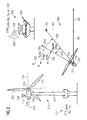
- Fig.2 shows an exemplary scenario of an off-shore wind park installation 200 thereby illustrating a determination of a yaw direction of a wind turbine according to the proposed solution.
- an off-shore wind turbine 210 is located at a specific geographic position 211.
- the geographic position 211 may be exemplarily defined according the UTM (Universal Transverse Mercator) coordinate system comprising a first datum or coordinate X 1 (also called “eastings") and a second datum or coordinate Y 1 (also called “northings").
- UTM Universal Transverse Mercator
- the wind turbine 210 comprises a nacelle 216 being rotatable mounted on top of a tower 217 via a yawing system 219.
- a rotor is attached to an upwind side of the nacelle 216.
- the rotor includes a central rotor hub 213 and a plurality of blades 212 mounted to and extending radially from the rotor hub 213 defining a rotor plane 220.
- the nacelle 216 may be involved in a yawing movement, e.g., rotating the rotor plane 220 perpendicular to an incoming wind.
- an electrical substation 230 is located at a specific geographic position 231 which is different from the geographic position 211 of the wind turbine 210.
- the geographic position 231 may be also defined according the UTM (Universal Transverse Mercator) coordinate system comprising a first datum or coordinate X 2 and a second datum or coordinate Y 2 .
- UTM Universal Transverse Mercator
- the substation 230 includes a transmitter 232 representing a source of a radio signal 233 being broadcasted to be processed with the help of a Radio Direction Finding (RDF) method.
- RDF Radio Direction Finding
- Radio Direction Finding refers to the determination of a direction from which a received signal is transmitted thereby using a specialized antenna or antenna system in combination with triangulation to identify the precise location or direction of a transmitter, i.e. the source of the broadcasted signal. This may exemplarily refer to radio or to other forms of wireless communication.
- the signal 233 broadcasted from the transmitter 232 is received by a receiver 215 attached on top of the nacelle 216.
- the receiver 215 comprises an antenna 218, both configured as a Radio Direction Finder or RDF receiver for finding or determining a direction towards the source 232 of the signal 233.
- the antenna 218 is configured according to a single-channel RDF system which is based on the use of a multi-antenna array in combination with the receiver 215 as a single channel radio receiver.
- the antenna array 218 may be installed or calibrated such on the top of the nacelle 216, that a 0°-position or 0°-direction of the RDF receiver is equal to a forward facing direction of the wind turbine 210, i.e., is in line with an actual yaw direction 214 of the nacelle 216.
- the applied RDF method is based on a Pseudo-Doppler method ("Doppler-RDF").
- Doppler-DRF is a phase-based direction finding method producing a direction estimate based on the received signal 233 by measuring a Doppler-shift induced on the signal at the antenna 218 of the RDF receiver by sampling around the elements of a circular antenna array.
- Fig.3 exemplarily illustrates in a schematic view the principle of the original Doppler-RDF using a single antenna 310 that physically moves along a circle or rotating platform 320.
- the antenna 310 detects a signal with a shorter wavelength, i.e. a signal with a higher frequency.
- the antenna 310 detects a signal with a longer wavelength, i.e. a signal with a lower frequency.
- an antenna mounted on a rotating platform as shown in Fig.3 would detect a wavelength of the received signal which increases and decreases sinusoidal in relation to the frequency of the signal as originally emitted from the transmitter.
- Fig.4 illustrates in a graph 400 a more detailed view of a sinusoidal curve 410 representing the wavelength/frequency of a signal received via an antenna 310 as shown in Fig.3 .
- an abscissa 420 of the graph 400 is representing the angular position of the antenna 310
- an ordinate 430 is representing a Doppler-shift frequency of the received signal indicating a level of increase or decrease of the frequency of the received signal in relation to the frequency of the signal as originally emitted from the transmitter 350.
- the wavelength of the received signal is at a local minimum, i.e. the Doppler-shift frequency is at a maximum (i.e. position "D" in Fig.4 ).
- the wavelength of the received signal is unchanged, i.e. the Doppler-shift frequency is zero (i.e. at position "A” in Fig.4 ).
- the wavelength of the received signal is at a local maximum, i.e. the Doppler-shift frequency is at a minimum (i.e. at position "B" in Fig.4 ).
- the wavelength of the received signal is unchanged, i.e. the Doppler-shift frequency is zero (i.e. at position "C” in Fig.4 ).
- those sections in the graph 400 without any Doppler-shift, and in particular such areas in curve 410 marking an angular position with a decreasing "zero crossing" towards the abscissa 420 are representing those positions of the antenna 310 closest to the source of the signal (i.e. at position "A” in Fig.3 ).
- applying a decreasing zero crossing detection in graph 400 results in an accurate indication of the direction towards the source of the received signal.
- Fig.5 shows in a block diagram a possible embodiment of a Pseudo-Doppler RDF receiver 500.
- Pseudo-Doppler RDF is based on an antenna array 510 including multiple antennas 511...514. Each antenna 511...514 is connected to an antenna controller 520.
- the antenna controller 520 is connected to a FM (Frequency Modulation) receiver 530 which is communicating with a demodulator 521.
- the demodulator 521 is coupled to a band pass filter 532 which is connected to a zero-crossing detector 533.
- the antenna controller 520 is further connected to an antenna position selector/multiplexer 540 driven by a clocking signal unit 541.
- the antenna position selector/multiplexer 540 is further coupled to a direction comparator 542 which is also communicating with the zero-crossing detector 533.
- the direction comparator 542 is further communicating with an orientation output 543 indicating the resulting direction of the source of the signal received at the antenna array 510.
- signal reception at the antenna array 510 is rapidly shifted (indicated by a sequence "1-2-3-4" in Fig.5 ) from antenna to antenna 511...514 driven by the antenna position selector/multiplexer 540 in combination with the controller 520 thereby simulating a single antenna rotating rapidly on a disc.
- the rotation speed may be about 500 Hz.
- the received signal After receiving the frequency modulated signal via the antenna array 510 and further processing via the FM receiver 530, the received signal will be demodulated by the demodulator 531. After demodulation, the frequency of the processed signal is equal to the frequency of the pseudo antenna rotation. After a band pass filtering via the filter 532 the positions with decreasing zero-crossings of the Doppler-shift frequency can be identified by the zero-crossing-detector 533 in combination with the direction comparator 542. Based on the identified zero-crossings, the resulting direction from the antenna 510 towards or in relation to the source of the received signal will be indicated via the orientation output 543.
- a relative offset between the 0°-position/direction e.g. the actual yaw direction of the nacelle and the identified direction towards the source of the received signal may be also presented as a further result at the orientation output 543.
- the Pseudo-Doppler RDF receiver 500 as presented in Fig.5 may be part of a yaw encoder of the wind turbine.
- RDF Radio Direction Finding
- a transmitter representing the source of the signal may broadcast a steady signal at a constant reference frequency.
- the UHF frequency band 300 MHz to 1 GHz
- the preferred frequency range for the broadcast due to the following reasons:
- a further diagram 250 is embedded in Fig.2 visualizing in top-view a geographical situation of the off-shore scenario 200.
- the nacelle 216 is indicated in top-view together with the antenna 218 located at the origin of the diagram 250 representing the geographic position 211.
- the geographic location of the substation 230, in particular the geographic position 231 of the transmitter 232 is indicated at the upper right side of the diagram 250.
- the geographic positions 211, 231 maybe defined according to any geographic coordinate system enabling every location on earth to be specified by a set of numbers or letters which are also referred to as coordinates. Such coordinates are often chosen such that one of the numbers represents a vertical position and two or three of the numbers represent a horizontal position. Examples for geographic coordinate systems are "Geographic latitude and longitude” or “UTM” (Universal Transverse Mercator) and “UPS” (Universal Polar Stereographic).
- the diagram 250 is configured according to UTM wherein an abscissa 251 is exemplarily representing a cardinal direction "East" and an ordinate 252 is representing a cardinal direction "North”.
- the abscissa 251 may represent a "Longitude” information and the ordinate 252 may represent a "Latitude” information according to the Geographic Latitude and Longitude system.
- a relative cardinal direction or a relative compass heading between the antenna or antenna array 218 of the wind turbine 210 and the transmitter 232 will be determined by comparing, i.e., processing the respective coordinates (X 1 , Y 1 , X 2 , Y 2 ) of the geographic positions 211, 231 according to, e.g., triangular calculations.
- Such calculation of the relative compass heading based on a standardized geographic coordinate systems is well known and will be shortly summarized at the end of the description.
- the resulting relative compass heading is indicated by an arrow 253 in the geographic diagram 250.
- the relative compass heading 253 comprises a first coordinate (indicated by an arrow 260) representing the UTM-specific "eastings" and a second coordinate (indicated by an arrow 261) representing the UTM-specific "northings”.
- the relative compass heading 253 is permanent and will never change over time as long as the wind turbine 210, i.e. the antenna 218 and the substation 230, i.e. the transmitter 232 will remain at the same geographic position. Therefore, the relative compass heading 253 can be calculated individually for each wind turbine one-time and be stored into a configuration file as a reference information.
- the direction from the antenna 218 toward the transmitter 232 is the same or almost the same as the direction from the nacelle 216 toward the transmitter 232 and the same or almost the same as the direction from the wind turbine 210 towards the transmitter 232.
- the determined direction which is presented at the orientation output 543 of the Pseudo-Doppler RDF receiver 500 is equal or almost equal to the calculated relative compass heading 253.
- the determined direction and the relative compass heading are labeled with the same index 253 in the description hereinafter.
- the receiver 215 and the antenna 218 are calibrated such, that the 0°-direction is equal to the actual yaw direction 214 of the nacelle 216.
- a nacelle offset angle ⁇ NacelleOffset (indicated by an arrow 254 in the diagram 250) between the 0°-direction of the antenna 218 and the determined direction (which is equal to the calculated relative compass heading 253), can be derived.
- the actual yaw direction (indicated by an arrow 214 in the diagram 250) can be determined.
- a reference angle ⁇ UTM may be derived based on the relative compass heading 253 in relation to the cardinal direction "North" (indicated by the ordinate 252).
- the reference angle ⁇ UTM is indicated by an arrow 255 in the diagram 250.
- an absolute turbine yaw angle ⁇ YawAngle may be derived which is specific for each wind turbine 210 being part of the wind park installation 200.
- the absolute turbine yaw angle ⁇ YawAngle is indicated by an arrow 256 in the diagram 250.
- the absolute turbine yaw angle 256 or the actual yaw direction 214 may be either updated continuously or sporadically to determine the actual yaw direction 214 or any further information concerning the actual position or direction of the rotor plane 220 or heading of the wind turbine or to calibrate the existing yaw encoder.
- the proposed solution may be applicable to any wind turbines according to any of the following configurations:
- the proposed solution is independent from the design of the rotor or the nacelle, e.g., independent from the number of blades or from the shape of the nacelle.
- the proposed solution may be applicable to any Radio Direction Finding (RDF) method or technology capable for measuring or detecting the relative direction of a signal source.
- RDF Radio Direction Finding
- the proposed solution may be further applicable to any embodiment of a radio transmitter as a source for broadcasting a signal at any transmission frequency.
- the possible range of possible frequencies to be used for the proposed solution maybe within or outside the UHF frequency band.
- the proposed solution may be used for a constant or permanent monitoring of the yaw direction or yaw angle of a wind turbine or for a one-time only calibration of an existing yaw encoder.
- the transmitter 232 may be configured such, that the signal 233 is broadcasted only within defined time intervals like, e.g., every 24 hours. Accordingly, the receiver 215 mounted at the wind turbine has be activated, i.e. synchronized, within the same time intervals. Beneficially, power consumption can be reduced at transmitter side as well as on receiver side.
- the UTM (Universal Transverse Mercator) system of coordinates is a common system used in industry. This system breaks the globe into 60 zones each of which is then measured using meters north and east. These measurements are called “eastings” and “northings” and are designated as mE (meters east) and mN (meters north), respectively.
- the common function atan2( y , x ) can be used to identify which quadrant the angle is in.
- mod( a , b ) is the modulo function that returns the remainder of a divided by b.
- ⁇ mod ATAN ⁇ 2 ⁇ Easting ⁇ 2 - Easting ⁇ 1 , Northing ⁇ 2 - Northing ⁇ 1 * 180 / ⁇ + 360 , 360
- tan -1 ( x ) only gives correct answers for coordinates located in the Eastern Hemisphere of the globe when using the Decimal Degree format to represent latitude and longitude.
Abstract
- receiving at a component (216) of the wind turbine (210) a signal (233) broadcasted from a source (232),
- determining a direction (253) from the component (216) towards the source (232) based on the received signal (233),
- determining the yaw direction (214) of the wind turbine (210) in relation to the determined direction (253) towards the source (232).
Description
- The invention relates to a method, a wind turbine and to a device for determining a yaw direction of a wind turbine. In addition, an according computer program product and a computer readable medium are suggested.
- A wind turbine in operation will not always experience wind perpendicular to a rotor plane. When the rotor plane (which is also referred to as heading) of a wind turbine is not perpendicular to the wind, the efficiency will decrease. Therefore, actual wind turbines comprise a yaw system designed to automatically adjust their heading, like, e.g., rotating the rotor plane perpendicular to the incoming wind or to maintain an angle relative to the wind to maximize the surface area of the turbine rotor.
- Usually, the yaw system is part of a nacelle, which may be involved in a yawing movement, i.e. being rotatable mounted on top of a tower via at least one yaw bearing. A rotor is attached to an upwind side of the nacelle. The rotor is coupled via a drive train to a generator housed inside the nacelle. The rotor includes a central rotor hub and a plurality of blades mounted to and extending radially from the rotor hub defining the rotor plane.
- It is important for wind power plant operators to know an actual position or direction of the rotor plane or heading of the respective wind turbine, the plane or heading being correlated with an actual position or direction of the nacelle. The actual direction of the nacelle is also referred to as a yaw direction or a yaw position or, in relation to a predefined direction (e.g. a cardinal direction), as a yaw angle. Alternatively the yaw angle may be defined as the direction of the nacelle in relation of the direction of the incoming wind.
-
Fig.1 shows in a schematically top view an exemplary scenario of awind turbine 100 in relation to the well known cardinal points or compass points which are indicated as a compass rose in the background ofFig.1 . Arotor hub 120 including a plurality ofblades 130 defining arotor plane 140 is mounted at the upwind side of anacelle 110. According to the scenario ofFig.1 , an actual yaw direction 150 (which is also referred to as "compass heading") of thewind turbine 100, i.e. the actual direction of thenacelle 110 points towards the cardinal direction "North East" or "NE". As exemplarily shown inFig.1 , an absolute yaw angle "θYawAngle" is referencing theactual yaw direction 150 of the wind turbine in relation towards the cardinal direction "North" or "N". The absolute yaw angle θYawAngle is indicated by anarrow 160, wherein θYawAngle = 45°. - Information concerning the yaw direction is a common used basis for analyzing data concerning a wind turbine or performing sector management control like, e.g.,
- site wind mapping and historical data collection on wind patterns,
- limiting wind turbine noise by avoiding operation in wind directions where noise generation is excessive,
- automatic curtailment and regulation of a wind turbine at yaw angles where significant wind turbulence might be present,
- prevention of shadow flicker/light pollution for neighboring residents or businesses at certain times of day and yaw angles,
- remote manual control of a wind turbine yaw position,
- efficiency testing and wind turbine power curve validation, or
- safe positioning of the rotor during ice conditions when service teams are approaching.
- In order to determine, e.g., an absolute yaw angle, a wind turbine may be equipped with a yaw encoder, measuring the relative yaw direction in relation to a stationary object like, e.g., a tower being secured to a foundation at ground level. The yaw encoder is typically calibrated by determining a reference yaw direction or reference yaw angle after finalization of the wind turbine installation.
- In some scenarios the initial calibration of the yaw angle is incorrect or less accurate due to applying a rough estimate or rule of thumb to determine a cardinal direction as a basis or reference for the yaw angle calibration.
- A further possible reason for an inaccurate yaw angle calibration is a wind turbine installation based on a design including powerful permanent magnets, eliminating the possibility of applying magnetic compasses to determine the yaw direction or yaw angle. A magnetic compass, as a further general disadvantage, comprises inaccurateness per se, in particular at installations located at high geographic latitudes.
- Alternatively, compasses based on GPS (Global Positioning System) or other satellite-based positioning systems have been applied to determine the reference yaw direction of the wind turbine.
- [
EP 2 559 993 A1 ] refers to a method to determine the yaw angle of a component of a wind turbine wherein at least one receiver of an automated and autonomous positioning system is used to generate position-data of the receiver. The receiver is arranged at a wind turbine location being subjected to a yawing movement. - However, applying such kind of automated and autonomous positioning systems for calibration issues is restricted due to high costs and limited accuracy.
- The object is thus to overcome such disadvantages and in particular to provide an improved approach for determining an accurate yaw direction and/or yaw angle of a wind turbine.
- This problem is solved according to the features of the independent claims. Further embodiments result from the depending claims.
- In order to overcome this problem, a method is provided for determining a yaw direction of a wind turbine comprising the following steps,
- receiving at a component of the wind turbine a signal broadcasted from a source,
- determining a direction from the component towards the source based on the received signal,
- determining the yaw direction of the wind turbine in relation to the determined direction towards the source.
- Determining the yaw direction based on a received signal broadcasted from a source can be implemented into a wind turbine in a cost effective way. As a further advantage, no active yawing movement of the wind turbine is necessary to enable the determination of the yaw direction with sufficient accuracy, i.e., the determination of the yaw direction is possible even when the wind turbine is stationary.
- In an embodiment, the yaw direction is determined based on a Radio Direction Finding (RDF) method.
- In another embodiment, the Radio Direction Finding method is based on a Pseudo-Doppler method. Implementing RDF based on a Pseudo-Doppler method can be implemented at a very low cost wherein the results of the RDF are based on a high quality.
- In a further embodiment,
- the signal is received via an antenna and/or receiver being attached to the component, the antenna and/or receiver having a calibrated 0°-direction in relation to a direction of the component,
- an offset angle is determined based on the calibrated 0°-direction in relation to the determined direction,
- the yaw direction is determined based on the offset angle and the determined direction.
- In a next embodiment,
- the signal is broadcasted from the source located at a source-specific geographic position,
- the broadcasted signal is received at a component-specific geographic position,
- a relative compass heading is derived by processing the component-specific geographic position and the source-specific geographic position,
- a yaw angle of the wind turbine is derived based
- on the offset angle, and
- on the relative compass heading.
- The relative compass heading or the relative cardinal direction between the receiver and transmitter of a broadcasted signal may be determined by comparing, i.e., processing respective coordinates of the geographic positions according to, e.g., triangular calculations. Such processing based on standardized geographic coordinate systems is well known and will be shortly summarized at the end of the description.
- It is also an embodiment that the yaw angle is determined in relation towards a defined cardinal direction. By determining the yaw angle in relation towards a defined cardinal direction the resulting yaw direction and/or yaw angle (which is also referred to as "absolute yaw direction and/or angle") can be determined with sufficient accuracy for each wind turbine of a wind park installation individually. As an example, the individual yaw angle/direction may be determined for each wind turbine in relation to the cardinal direction "North".
- Pursuant to another embodiment, the broadcasted signal is received at a nacelle or rotor of the wind turbine. Basically, the broadcasted signal may be received via an antenna or receiver located at any part of the wind turbine being involved in yawing or rotating movement causing a change in the direction between the antenna/receiver and the source of the signal.
- According to an embodiment, the yaw direction is determined
- continuously, or
- periodically, or
- within at least one defined time interval, or
- one-time.
- As an advantage, the power consumption of the transmitter can be optimized, i.e. the waste of energy minimized. As an example, for power consumption purposes, the transmitter could be timed to broadcast the signal at regular intervals (i.e. every 24 hours) in conjunction with receivers mounted on the wind turbine.
- According to another embodiment, the geographic position is defined according to
- a Geographic Latitude and Longitude coordinate system, or
- an Universal Transverse Mercator (UTM) coordinate system, or
- an Universal Polar Stereographic (UPS) coordinate system.
- The problem stated above is also solved by a wind turbine comprising
- a receiver for receiving a signal broadcasted from a source,
- a processing unit that is arranged for
- determining a direction from the receiver towards the source based on the received signal,
- determining the yaw direction of the wind turbine in relation to the determined direction towards the source.
- The problem stated above is also solved by a device comprising and/or being associated with a processor unit and/or hard-wired circuit and/or a logic device that is arranged such that the method as described herein is executable thereon.
- In a further embodiment, the device is a yaw encoder.
- The solution provided herein further comprises a computer program product directly loadable into a memory of a digital computer, comprising software code portions for performing the steps of the method as described herein.
- In addition, the problem stated above, is solved by a computer readable medium, having computer-executable instructions adapted to cause a computer system to perform the steps of the method as described herein.
- Embodiments of the invention are shown and illustrated in the following figures:
- Fig.2
- shows an exemplary scenario of an off-shore wind park installation;
- Fig.3
- exemplarily illustrates in a schematic view a basic principle of the original Doppler-RDF;
- Fig.4
- illustrates in a graph a more detailed view of a sinusoidal curve representing the wavelength/frequency of a received signal according to Doppler-RDF;
- Fig.5
- shows in a block diagram a possible embodiment of a Pseudo-Doppler RDF receiver.
-
Fig.2 shows an exemplary scenario of an off-shorewind park installation 200 thereby illustrating a determination of a yaw direction of a wind turbine according to the proposed solution. - According to the example of
Fig.2 an off-shore wind turbine 210 is located at a specificgeographic position 211. Thegeographic position 211 may be exemplarily defined according the UTM (Universal Transverse Mercator) coordinate system comprising a first datum or coordinate X1 (also called "eastings") and a second datum or coordinate Y1 (also called "northings"). - The
wind turbine 210 comprises anacelle 216 being rotatable mounted on top of atower 217 via ayawing system 219. A rotor is attached to an upwind side of thenacelle 216. The rotor includes acentral rotor hub 213 and a plurality ofblades 212 mounted to and extending radially from therotor hub 213 defining arotor plane 220. - The
nacelle 216 may be involved in a yawing movement, e.g., rotating therotor plane 220 perpendicular to an incoming wind. - As a further exemplary member of the off-shore
wind park installation 200 anelectrical substation 230 is located at a specificgeographic position 231 which is different from thegeographic position 211 of thewind turbine 210. Thegeographic position 231 may be also defined according the UTM (Universal Transverse Mercator) coordinate system comprising a first datum or coordinate X2 and a second datum or coordinate Y2. - The
substation 230 includes atransmitter 232 representing a source of aradio signal 233 being broadcasted to be processed with the help of a Radio Direction Finding (RDF) method. - Radio Direction Finding (RDF) refers to the determination of a direction from which a received signal is transmitted thereby using a specialized antenna or antenna system in combination with triangulation to identify the precise location or direction of a transmitter, i.e. the source of the broadcasted signal. This may exemplarily refer to radio or to other forms of wireless communication.
- As shown in
Fig.2 , thesignal 233 broadcasted from thetransmitter 232 is received by areceiver 215 attached on top of thenacelle 216. According to the proposed solution, thereceiver 215 comprises anantenna 218, both configured as a Radio Direction Finder or RDF receiver for finding or determining a direction towards thesource 232 of thesignal 233. In thescenario 200, theantenna 218 is configured according to a single-channel RDF system which is based on the use of a multi-antenna array in combination with thereceiver 215 as a single channel radio receiver. - Thereby, the
antenna array 218 may be installed or calibrated such on the top of thenacelle 216, that a 0°-position or 0°-direction of the RDF receiver is equal to a forward facing direction of thewind turbine 210, i.e., is in line with anactual yaw direction 214 of thenacelle 216. - Two main categories are applicable for single-channel direction finding:
- direction finding based on amplitude comparison
- direction finding based on phase comparison
- According to an exemplary embodiment of the
scenario 200 illustrated inFig.2 , the applied RDF method is based on a Pseudo-Doppler method ("Doppler-RDF"). Doppler-DRF is a phase-based direction finding method producing a direction estimate based on the receivedsignal 233 by measuring a Doppler-shift induced on the signal at theantenna 218 of the RDF receiver by sampling around the elements of a circular antenna array. -
Fig.3 exemplarily illustrates in a schematic view the principle of the original Doppler-RDF using asingle antenna 310 that physically moves along a circle orrotating platform 320. In short, when theantenna 310 moves in adirection 330 towards atransmitter 350 representing a source of a signal, theantenna 310 detects a signal with a shorter wavelength, i.e. a signal with a higher frequency. On the contrary, when theantenna 310 is moving in adirection 340 away from thetransmitter 350, theantenna 310 detects a signal with a longer wavelength, i.e. a signal with a lower frequency. - Using this principle, an antenna mounted on a rotating platform as shown in
Fig.3 would detect a wavelength of the received signal which increases and decreases sinusoidal in relation to the frequency of the signal as originally emitted from the transmitter. -
Fig.4 illustrates in a graph 400 a more detailed view of asinusoidal curve 410 representing the wavelength/frequency of a signal received via anantenna 310 as shown inFig.3 . Thereby, anabscissa 420 of thegraph 400 is representing the angular position of theantenna 310 and anordinate 430 is representing a Doppler-shift frequency of the received signal indicating a level of increase or decrease of the frequency of the received signal in relation to the frequency of the signal as originally emitted from thetransmitter 350. - When the
antenna 310 is moving towards (i.e. towards direction 330) the source 350 (i.e. position "D" inFig.3 ), the wavelength of the received signal is at a local minimum, i.e. the Doppler-shift frequency is at a maximum (i.e. position "D" inFig.4 ). - When the
antenna 310 is at a position nearest to the source of the signal (i.e. at position "A" inFig.3 ) the wavelength of the received signal is unchanged, i.e. the Doppler-shift frequency is zero (i.e. at position "A" inFig.4 ). - When the
antenna 310 is moving away (i.e. towards direction 340) from the source 350 (i.e. at position "B" inFig.3 ) the wavelength of the received signal is at a local maximum, i.e. the Doppler-shift frequency is at a minimum (i.e. at position "B" inFig.4 ). - When the
antenna 310 is at a position with a maximum distance to thesource 350 of the signal (i.e. at position "C" inFig.3 ) the wavelength of the received signal is unchanged, i.e. the Doppler-shift frequency is zero (i.e. at position "C" inFig.4 ). - Consequently, those sections in the
graph 400 without any Doppler-shift, and in particular such areas incurve 410 marking an angular position with a decreasing "zero crossing" towards the abscissa 420 (i.e. position "A" in the curve 410) are representing those positions of theantenna 310 closest to the source of the signal (i.e. at position "A" inFig.3 ). Thus, applying a decreasing zero crossing detection ingraph 400 results in an accurate indication of the direction towards the source of the received signal. - In practical applications of Doppler-RDF a physically rotating disc would have to be moving at a very high rotating velocity to make the Doppler-shift "visible". Because of this limitation, Pseudo-Doppler RDF was developed simulating the rotation of the antenna disc electronically.
-
Fig.5 shows in a block diagram a possible embodiment of aPseudo-Doppler RDF receiver 500. Pseudo-Doppler RDF is based on anantenna array 510 includingmultiple antennas 511...514. Eachantenna 511...514 is connected to anantenna controller 520. Theantenna controller 520 is connected to a FM (Frequency Modulation)receiver 530 which is communicating with a demodulator 521. The demodulator 521 is coupled to aband pass filter 532 which is connected to a zero-crossingdetector 533. - The
antenna controller 520 is further connected to an antenna position selector/multiplexer 540 driven by aclocking signal unit 541. The antenna position selector/multiplexer 540 is further coupled to adirection comparator 542 which is also communicating with the zero-crossingdetector 533. Thedirection comparator 542 is further communicating with anorientation output 543 indicating the resulting direction of the source of the signal received at theantenna array 510. - According to
Fig.5 , signal reception at theantenna array 510 is rapidly shifted (indicated by a sequence "1-2-3-4" inFig.5 ) from antenna toantenna 511...514 driven by the antenna position selector/multiplexer 540 in combination with thecontroller 520 thereby simulating a single antenna rotating rapidly on a disc. As an example, for UHF (Ultra High Frequency) signals the rotation speed may be about 500 Hz. - After receiving the frequency modulated signal via the
antenna array 510 and further processing via theFM receiver 530, the received signal will be demodulated by thedemodulator 531. After demodulation, the frequency of the processed signal is equal to the frequency of the pseudo antenna rotation. After a band pass filtering via thefilter 532 the positions with decreasing zero-crossings of the Doppler-shift frequency can be identified by the zero-crossing-detector 533 in combination with thedirection comparator 542. Based on the identified zero-crossings, the resulting direction from theantenna 510 towards or in relation to the source of the received signal will be indicated via theorientation output 543. - Further, dependent from the calibration of the 0°-position or 0°-direction of the
Pseudo-Doppler RDF receiver 500, a relative offset between the 0°-position/direction, e.g. the actual yaw direction of the nacelle and the identified direction towards the source of the received signal may be also presented as a further result at theorientation output 543. - The
Pseudo-Doppler RDF receiver 500 as presented inFig.5 may be part of a yaw encoder of the wind turbine. - It should be noted, that each kind of Radio Direction Finding (RDF) method may be used for implementing the proposed solution.
- Applying Pseudo-Doppler RDF may be the preferred solution for the following reasons:
- antenna array and processor can be sourced at very low cost,
- antenna array can be small for UHF frequency band (15 cm X 15 cm or smaller),
- small individual antenna length (whip style length around 19 cm for 400 MHz),
- high degree of accuracy (<1 degree to 5 degrees depending on design),
- possibility to identify beacon direction at all angles, and
- no direction aliasing
- Regarding the signal being broadcasted, a transmitter representing the source of the signal may broadcast a steady signal at a constant reference frequency. As an example, the UHF frequency band (300 MHz to 1 GHz) may be the preferred frequency range for the broadcast due to the following reasons:
- multiple UHF frequencies are available for public use,
- UHF allows the use of compact antenna systems (<1m), and
- UHF is best for medium range line of site applications such as a large wind farms
- In the following, the determination of the actual yaw direction of wind turbine according to the proposed solution will be explained in more detail.
- For that, a further diagram 250 is embedded in
Fig.2 visualizing in top-view a geographical situation of the off-shore scenario 200. At the bottom left side of the diagram 250 thenacelle 216 is indicated in top-view together with theantenna 218 located at the origin of the diagram 250 representing thegeographic position 211. Accordingly, the geographic location of thesubstation 230, in particular thegeographic position 231 of thetransmitter 232 is indicated at the upper right side of the diagram 250. - It should be noted, that the
geographic positions - In the example shown in
Fig.2 , the diagram 250 is configured according to UTM wherein anabscissa 251 is exemplarily representing a cardinal direction "East" and anordinate 252 is representing a cardinal direction "North". - Alternatively, the
abscissa 251 may represent a "Longitude" information and theordinate 252 may represent a "Latitude" information according to the Geographic Latitude and Longitude system. - According to a first step of the proposed solution, a relative cardinal direction or a relative compass heading between the antenna or
antenna array 218 of thewind turbine 210 and thetransmitter 232 will be determined by comparing, i.e., processing the respective coordinates (X1, Y1, X2, Y2) of thegeographic positions - The resulting relative compass heading is indicated by an
arrow 253 in the geographic diagram 250. According toFig.2 , the relative compass heading 253 comprises a first coordinate (indicated by an arrow 260) representing the UTM-specific "eastings" and a second coordinate (indicated by an arrow 261) representing the UTM-specific "northings". - The relative compass heading 253 is permanent and will never change over time as long as the
wind turbine 210, i.e. theantenna 218 and thesubstation 230, i.e. thetransmitter 232 will remain at the same geographic position. Therefore, the relative compass heading 253 can be calculated individually for each wind turbine one-time and be stored into a configuration file as a reference information. - In a next step, by applying the Pseudo-Doppler RDF based on the
signal 233 received at thereceiver 215 via theantenna 218, the direction from theantenna 218 towards thetransmitter 232 is determined. - It should be noted, that the direction from the
antenna 218 toward thetransmitter 232 is the same or almost the same as the direction from thenacelle 216 toward thetransmitter 232 and the same or almost the same as the direction from thewind turbine 210 towards thetransmitter 232. - Further, the determined direction which is presented at the
orientation output 543 of thePseudo-Doppler RDF receiver 500 is equal or almost equal to the calculated relative compass heading 253. Thus, the determined direction and the relative compass heading are labeled with thesame index 253 in the description hereinafter. - As already mentioned above, the
receiver 215 and theantenna 218 are calibrated such, that the 0°-direction is equal to theactual yaw direction 214 of thenacelle 216. - Consequently, as a further output of the Pseudo-Doppler RDF, a nacelle offset angle θNacelleOffset (indicated by an
arrow 254 in the diagram 250) between the 0°-direction of theantenna 218 and the determined direction (which is equal to the calculated relative compass heading 253), can be derived. Based on the determined direction and the offsetangle 254 the actual yaw direction (indicated by anarrow 214 in the diagram 250) can be determined. - Based on the offset
angle 254 and/or theactual yaw direction 214 and based on the calculated relative compass heading 253 further geographic information may be derived dependent on the orientation or calibration of the geographic diagram 250. - As an example, a reference angle θUTM may be derived based on the relative compass heading 253 in relation to the cardinal direction "North" (indicated by the ordinate 252). The reference angle θUTM is indicated by an
arrow 255 in the diagram 250. - Further, by subtracting the offset
angle 254 from thereference angle 255 an absolute turbine yaw angle θYawAngle may be derived which is specific for eachwind turbine 210 being part of thewind park installation 200. The absolute turbine yaw angle θYawAngle is indicated by anarrow 256 in the diagram 250. - The absolute
turbine yaw angle 256 or theactual yaw direction 214 may be either updated continuously or sporadically to determine theactual yaw direction 214 or any further information concerning the actual position or direction of therotor plane 220 or heading of the wind turbine or to calibrate the existing yaw encoder. - The proposed solution may be applicable to any wind turbines according to any of the following configurations:
- front mounted rotor (Forward facing) with active yaw,
- rear mounted rotor (Rear facing) with active yaw,
- any non-traditional direction dependent rotor configurations,
- any passive yaw wind turbine with a direction dependent rotor configuration
- The proposed solution is independent from the design of the rotor or the nacelle, e.g., independent from the number of blades or from the shape of the nacelle.
- Further, the proposed solution may be applicable to any Radio Direction Finding (RDF) method or technology capable for measuring or detecting the relative direction of a signal source.
- The proposed solution may be further applicable to any embodiment of a radio transmitter as a source for broadcasting a signal at any transmission frequency. The possible range of possible frequencies to be used for the proposed solution maybe within or outside the UHF frequency band.
- The proposed solution may be used for a constant or permanent monitoring of the yaw direction or yaw angle of a wind turbine or for a one-time only calibration of an existing yaw encoder.
- According to a further embodiment of the proposed solution, the
transmitter 232 may be configured such, that thesignal 233 is broadcasted only within defined time intervals like, e.g., every 24 hours. Accordingly, thereceiver 215 mounted at the wind turbine has be activated, i.e. synchronized, within the same time intervals. Beneficially, power consumption can be reduced at transmitter side as well as on receiver side. - The UTM (Universal Transverse Mercator) system of coordinates is a common system used in industry. This system breaks the globe into 60 zones each of which is then measured using meters north and east. These measurements are called "eastings" and "northings" and are designated as mE (meters east) and mN (meters north), respectively.
- In nearly all cases a wind farm will exist entirely within one of the 60 zones. In the event that it falls on the border between two zones, it will be important that both the turbine and the reference point are in the same zone.
- Calculating an angle from one point to another using UTM coordinates is straightforward. To determine a bearing θ, (which is corresponding with the
reference angle 255 ofFig.2 ) from the turbine coordinates (Easting1 (i.e. X1 inFig.2 ), Northing1 (i . e. Y1 inFig.2 )) to a reference coordinate (Easting2 (i . e. X2 inFig.2 ), Northing2 (i . e. Y2 inFig.2 )) the following equation can be used:
- The expression tan-1(x) will only calculate the correct bearing when the reference coordinate is to the northeast of the turbine coordinate.
- This is because


- To correct this, the common function atan2(y,x) can be used to identify which quadrant the angle is in.
- The results of atan2(y,x) will show angles greater than 180° as negative numbers. To convert this result to a range from 0° to 360° the following expression can be used:

- Here mod(a,b) is the modulo function that returns the remainder of a divided by b.
- The only thing remaining is to make sure that the result of atan2(x,y) is converted back to degrees by using the relation below.

- By combining this all it is possible to calculate the bearing θ from one UTM coordinate to the other. As an example, a line of computer code could be written as the following:

- In place of using UTM coordinates, it is also possible to use the more traditional latitude and longitude coordinates. Calculating a bearing using this coordinate system is a bit more complicated; although it is still possible using simple trigonometric functions.
- Approximating the earth as a sphere, the initial bearing θ from the turbine coordinate (long1 (i . e. X1 in
Fig.2 ), lat1 (i . e. Y1 inFig.2 )) to the reference coordinate (long2 (i.e. X2 inFig.2 ), lat2 (i . e. Y2 inFig.2 )) can be calculated using the following equation:
- However, for short distances, such as those on a wind farm, the lines of longitude around the earth can be considered to be parallel. Using this simplification the complex equation above can be simplified to the following:

- The expression tan-1(x) only gives correct answers for coordinates located in the Eastern Hemisphere of the globe when using the Decimal Degree format to represent latitude and longitude.
- Therefore, this function will also use atan2(y,x). Similarly, mod(a,b) is also used as before.
- It is also necessary to make sure that the angle within the cos(x) function is expressed as radians and that the result of atan2(x,y) is converted back to degrees by using the relationship between degrees and radians above.
- By combining this all it is possible to calculate the bearing θ from the turbine coordinate to the reference coordinate. As an example a line of computer code could be written as the following:

- Although the invention is described in detail by the embodiments above, it is noted that the invention is not at all limited to such embodiments. In particular, alternatives can be derived by a person skilled in the art from the exemplary embodiments and the illustrations without exceeding the scope of this invention.
Claims (14)
- A method for determining a yaw direction (214) of a wind turbine (210) comprising the following steps,- receiving at a component (216) of the wind turbine (210) a signal (233) broadcasted from a source (232),- determining a direction (253) from the component (216) towards the source (232) based on the received signal (233),- determining the yaw direction (214) of the wind turbine (210) in relation to the determined direction (253) towards the source (232).
- The method according to claim 1, wherein
the yaw direction (214) is determined based on a Radio Direction Finding (RDF) method. - The method according to claim 2, wherein
the Radio Direction Finding method is based on a Pseudo-Doppler method. - The method according to any of the preceding claims,
wherein- the signal (233) is received via an antenna (218) and/or receiver (215) being attached to the component (216), the antenna (218) and/or receiver (215) having a calibrated 0°-direction in relation to a direction of the component (216),- an offset angle (254) is determined based on the calibrated 0°-direction in relation to the determined direction (253),- the yaw direction (214) is determined based on the offset angle (254) and the determined direction (253). - The method according to claim 4, wherein- the signal (233) is broadcasted from the source (232) located at a source-specific geographic position (231),- the broadcasted signal (233) is received at a component-specific geographic position (211),- a relative compass heading is derived by processing the component-specific geographic position (211) and the source-specific geographic position (231),- a yaw angle (256) of the wind turbine (210) is derived based- on the offset angle (254), and- on the relative compass heading.
- The method according to claim 5, wherein
the yaw angle (256) is determined in relation towards a defined cardinal direction (252). - The method according to any of the preceding claims,
wherein
the broadcasted signal (233) is received at a nacelle or rotor of the wind turbine. - The method according any of the preceding claims, wherein
the yaw direction (214) is determined- continuously, or- periodically, or- within at least one defined time interval, or- one-time. - The method according any of the preceding claims, wherein
the geographic position (211, 231) is defined according to- a Geographic Latitude and Longitude coordinate system, or- an Universal Transverse Mercator (UTM) coordinate system, or- an Universal Polar Stereographic (UPS) coordinate system. - A wind turbine, comprising- a receiver (215, 218) for receiving a signal (233) broadcasted from a source (232),- a processing unit (215) that is arranged for- determining a direction (253) from the receiver (215) towards the source (232) based on the received signal (233),- determining a yaw direction (214) of the wind turbine (210) in relation to the determined direction (253) towards the source (232).
- A device comprising and/or being associated with a processor unit and/or hard-wired circuit and/or a logic device that is arranged such that the method according to any of the preceding claims 1 to 9 is executable thereon.
- The device according to claim 11, wherein the device is a yaw encoder.
- A computer program product directly loadable into a memory of a digital computer, comprising software code portions for performing the steps of the method according to any of the claims 1 to 9.
- A computer readable medium, having computer-executable instructions adapted to cause a computer system to perform the steps of the method according to any of the claims 1 to 9.
Priority Applications (3)
| Application Number | Priority Date | Filing Date | Title |
|---|---|---|---|
| EP14179302.6A EP2980404A1 (en) | 2014-07-31 | 2014-07-31 | Determining a yaw direction of a wind turbine |
| US14/705,096 US9958528B2 (en) | 2014-07-31 | 2015-05-06 | Determining a yaw direction of a wind turbine |
| CN201510466042.9A CN105317626B (en) | 2014-07-31 | 2015-07-31 | Determining a yaw direction of a wind turbine |
Applications Claiming Priority (1)
| Application Number | Priority Date | Filing Date | Title |
|---|---|---|---|
| EP14179302.6A EP2980404A1 (en) | 2014-07-31 | 2014-07-31 | Determining a yaw direction of a wind turbine |
Publications (1)
| Publication Number | Publication Date |
|---|---|
| EP2980404A1 true EP2980404A1 (en) | 2016-02-03 |
Family
ID=51265544
Family Applications (1)
| Application Number | Title | Priority Date | Filing Date |
|---|---|---|---|
| EP14179302.6A Withdrawn EP2980404A1 (en) | 2014-07-31 | 2014-07-31 | Determining a yaw direction of a wind turbine |
Country Status (3)
| Country | Link |
|---|---|
| US (1) | US9958528B2 (en) |
| EP (1) | EP2980404A1 (en) |
| CN (1) | CN105317626B (en) |
Cited By (5)
| Publication number | Priority date | Publication date | Assignee | Title |
|---|---|---|---|---|
| CN107620669A (en) * | 2017-10-18 | 2018-01-23 | 曲阜师范大学 | A kind of superconducting excited motor wind-force magnetic suspension device for regulating direction |
| WO2018177615A1 (en) * | 2017-03-31 | 2018-10-04 | Siemens Wind Power A/S | Determining an orientation of a rotor plane of a wind turbine |
| CN111726739A (en) * | 2020-07-08 | 2020-09-29 | 程鹏 | Self-generating communication broadcasting station convenient to install |
| CN112855438A (en) * | 2019-11-28 | 2021-05-28 | 北京国电思达科技有限公司 | Wind dynamic compensation method for wind power generation set yaw |
| CN113187671A (en) * | 2021-04-27 | 2021-07-30 | 南京韦博智控科技有限公司 | Method for determining yaw angle of wind wheel by using unmanned aerial vehicle |
Families Citing this family (8)
| Publication number | Priority date | Publication date | Assignee | Title |
|---|---|---|---|---|
| US20200248666A1 (en) * | 2016-12-08 | 2020-08-06 | Cytroniq Co., Ltd | Energy converting apparatus, energy converting system including same, and operating method thereof |
| CN107178469B (en) * | 2017-06-29 | 2019-02-15 | 北京金风科创风电设备有限公司 | The bearing calibration of the yaw angle angle value of wind power generating set and device |
| CN110094297B (en) * | 2018-01-31 | 2020-04-14 | 北京金风科创风电设备有限公司 | Control method and control system of wind generating set based on sectors |
| US10815966B1 (en) | 2018-02-01 | 2020-10-27 | Uptake Technologies, Inc. | Computer system and method for determining an orientation of a wind turbine nacelle |
| US10612521B2 (en) * | 2018-03-05 | 2020-04-07 | General Electric Company | Wind turbine shadow flicker management system |
| US11952983B2 (en) * | 2019-12-20 | 2024-04-09 | Vestas Wind Systems A/S | Method of determining orientation of a nacelle |
| CN114076064B (en) * | 2020-08-10 | 2023-11-28 | 北京金风科创风电设备有限公司 | Method and device for determining yaw 0-degree azimuth angle and yaw direction |
| CN112083736B (en) * | 2020-08-11 | 2023-07-25 | 广东电网有限责任公司电力科学研究院 | Unmanned aerial vehicle tracking method |
Citations (6)
| Publication number | Priority date | Publication date | Assignee | Title |
|---|---|---|---|---|
| US5321410A (en) * | 1988-06-09 | 1994-06-14 | Southwest Research Institute | Adaptive doppler DF system |
| US5426438A (en) * | 1992-12-30 | 1995-06-20 | Delfin Systems | Method and apparatus for adaptively determining the bearing angle of a radio frequency signal |
| US5977913A (en) * | 1997-02-07 | 1999-11-02 | Dominion Wireless | Method and apparatus for tracking and locating personnel |
| US20100143128A1 (en) * | 2008-12-23 | 2010-06-10 | General Electric Company | Wind turbine yaw bearing determination |
| US20110268569A1 (en) * | 2010-12-20 | 2011-11-03 | Friedrich Loh | Method for controlling a wind turbine, and wind turbine arrangement |
| EP2559993A2 (en) | 2011-08-18 | 2013-02-20 | Hitachi Ltd. | X-ray diffraction instrument for measuring an object larger than the x-ray detector |
Family Cites Families (8)
| Publication number | Priority date | Publication date | Assignee | Title |
|---|---|---|---|---|
| US6788199B2 (en) * | 2001-03-12 | 2004-09-07 | Eureka Technology Partners, Llc | Article locator system |
| EP2017468A1 (en) * | 2007-07-20 | 2009-01-21 | Siemens Aktiengesellschaft | Method for wind turbine yaw control |
| US20100092289A1 (en) * | 2008-10-10 | 2010-04-15 | General Electric Wind Energy Gmbh | Systems and methods involving wind turbine bearing detection and operation |
| EP2239462A1 (en) * | 2009-04-07 | 2010-10-13 | Siemens Aktiengesellschaft | Method and arrangement to measure the deflection of a wind-turbine blade |
| US8317471B2 (en) * | 2011-11-29 | 2012-11-27 | General Electric Company | Method for preventing rotor overspeed of a wind turbine |
| DK2599993T3 (en) * | 2011-12-01 | 2016-06-06 | Siemens Ag | A method for determining krøjningsvinklen of a component of a wind turbine |
| US20130317748A1 (en) * | 2012-05-22 | 2013-11-28 | John M. Obrecht | Method and system for wind velocity field measurements on a wind farm |
| US9347789B2 (en) * | 2013-09-18 | 2016-05-24 | Raymond Halsey Briant | Application and device to memorialize and share events geographically |
-
2014
- 2014-07-31 EP EP14179302.6A patent/EP2980404A1/en not_active Withdrawn
-
2015
- 2015-05-06 US US14/705,096 patent/US9958528B2/en not_active Expired - Fee Related
- 2015-07-31 CN CN201510466042.9A patent/CN105317626B/en not_active Expired - Fee Related
Patent Citations (6)
| Publication number | Priority date | Publication date | Assignee | Title |
|---|---|---|---|---|
| US5321410A (en) * | 1988-06-09 | 1994-06-14 | Southwest Research Institute | Adaptive doppler DF system |
| US5426438A (en) * | 1992-12-30 | 1995-06-20 | Delfin Systems | Method and apparatus for adaptively determining the bearing angle of a radio frequency signal |
| US5977913A (en) * | 1997-02-07 | 1999-11-02 | Dominion Wireless | Method and apparatus for tracking and locating personnel |
| US20100143128A1 (en) * | 2008-12-23 | 2010-06-10 | General Electric Company | Wind turbine yaw bearing determination |
| US20110268569A1 (en) * | 2010-12-20 | 2011-11-03 | Friedrich Loh | Method for controlling a wind turbine, and wind turbine arrangement |
| EP2559993A2 (en) | 2011-08-18 | 2013-02-20 | Hitachi Ltd. | X-ray diffraction instrument for measuring an object larger than the x-ray detector |
Cited By (10)
| Publication number | Priority date | Publication date | Assignee | Title |
|---|---|---|---|---|
| WO2018177615A1 (en) * | 2017-03-31 | 2018-10-04 | Siemens Wind Power A/S | Determining an orientation of a rotor plane of a wind turbine |
| CN110475966A (en) * | 2017-03-31 | 2019-11-19 | 西门子歌美飒可再生能源公司 | Determine the orientation of the rotor plane of wind turbine |
| US11384737B2 (en) | 2017-03-31 | 2022-07-12 | Siemens Gamesa Renewable Energy A/S | Determining an orientation of a rotor plane of a wind turbine |
| CN107620669A (en) * | 2017-10-18 | 2018-01-23 | 曲阜师范大学 | A kind of superconducting excited motor wind-force magnetic suspension device for regulating direction |
| CN107620669B (en) * | 2017-10-18 | 2023-06-16 | 曲阜师范大学 | Wind power magnetic suspension direction regulating device of superconducting excitation motor |
| CN112855438A (en) * | 2019-11-28 | 2021-05-28 | 北京国电思达科技有限公司 | Wind dynamic compensation method for wind power generation set yaw |
| CN111726739A (en) * | 2020-07-08 | 2020-09-29 | 程鹏 | Self-generating communication broadcasting station convenient to install |
| CN111726739B (en) * | 2020-07-08 | 2022-01-07 | 扬州科丰高新产业投资开发集团有限公司 | Self-generating communication broadcasting station convenient to install |
| CN113187671A (en) * | 2021-04-27 | 2021-07-30 | 南京韦博智控科技有限公司 | Method for determining yaw angle of wind wheel by using unmanned aerial vehicle |
| CN113187671B (en) * | 2021-04-27 | 2022-05-06 | 南京韦博智控科技有限公司 | Method for determining yaw angle of wind wheel by using unmanned aerial vehicle |
Also Published As
| Publication number | Publication date |
|---|---|
| US20160032897A1 (en) | 2016-02-04 |
| CN105317626B (en) | 2020-10-23 |
| CN105317626A (en) | 2016-02-10 |
| US9958528B2 (en) | 2018-05-01 |
Similar Documents
| Publication | Publication Date | Title |
|---|---|---|
| US9958528B2 (en) | Determining a yaw direction of a wind turbine | |
| EP3580451B1 (en) | Determining an orientation of a rotor plane of a wind turbine | |
| EP2599993B1 (en) | Method to determine the yaw angle of a component of a wind turbine | |
| CN104391281A (en) | Method for improving sky-wave radar sea surface ship target tracking and positioning precision | |
| CN202178871U (en) | Positioning system for indoor airships | |
| EP3181896A1 (en) | Calibrating a yaw system of a wind turbine | |
| Specht et al. | A history of maritime radio-navigation positioning systems used in Poland | |
| CN101825056A (en) | Wind turbine yaw bearing determination | |
| CN107607919B (en) | Method for measuring directional diagram of buoy-based/ship-based high-frequency ground wave radar receiving antenna | |
| CN105203993A (en) | Underground-pipeline three-point position indicator and working method thereof | |
| CN204925382U (en) | Positioning system , positioner and locator | |
| JP2017026444A (en) | Reflection type radar receiver and secondary surveillance radar system | |
| JP5733803B2 (en) | Radar link device | |
| CN113631952A (en) | Wind turbine with sea level wave characteristic determination | |
| US10809369B2 (en) | Radar signal processing apparatus and radar signal processing method | |
| JP6370121B2 (en) | Own ship positioning device, radar device, own mobile object positioning device, and own ship positioning method | |
| US20220235738A1 (en) | Method and device for determining a rotor orientation of a rotor of a wind turbine | |
| CN112556636B (en) | Method for calibrating receiving antenna by using GPS data provided by satellite | |
| Krol et al. | Fusion of Data Received from AIS and FMCW and Pulse Radar-Results of Performance Tests Conducted Using Hydrographical Vessels “Tukana” and “Zodiak” | |
| US9804254B2 (en) | Method for determining the timing of the receipt of a radio message | |
| Specht et al. | Polish DGPS system: 1995-2018–studies of reference station operating zones | |
| JP5127748B2 (en) | Question signal transmission method | |
| CN111164460A (en) | Electronic device, method and computer program for determining and using distances from matching constellation information | |
| WO2023037666A1 (en) | Monitoring device, management device, monitoring method, and management method | |
| Sa’Adah et al. | Tracking Position on GPS Smart Buoy System Using LoRa Communication |
Legal Events
| Date | Code | Title | Description |
|---|---|---|---|
| PUAI | Public reference made under article 153(3) epc to a published international application that has entered the european phase |
Free format text: ORIGINAL CODE: 0009012 |
|
| AK | Designated contracting states |
Kind code of ref document: A1 Designated state(s): AL AT BE BG CH CY CZ DE DK EE ES FI FR GB GR HR HU IE IS IT LI LT LU LV MC MK MT NL NO PL PT RO RS SE SI SK SM TR |
|
| AX | Request for extension of the european patent |
Extension state: BA ME |
|
| 17P | Request for examination filed |
Effective date: 20160720 |
|
| RBV | Designated contracting states (corrected) |
Designated state(s): AL AT BE BG CH CY CZ DE DK EE ES FI FR GB GR HR HU IE IS IT LI LT LU LV MC MK MT NL NO PL PT RO RS SE SI SK SM TR |
|
| RAP1 | Party data changed (applicant data changed or rights of an application transferred) |
Owner name: SIEMENS AKTIENGESELLSCHAFT |
|
| STAA | Information on the status of an ep patent application or granted ep patent |
Free format text: STATUS: EXAMINATION IS IN PROGRESS |
|
| 17Q | First examination report despatched |
Effective date: 20180704 |
|
| RAP1 | Party data changed (applicant data changed or rights of an application transferred) |
Owner name: SIEMENS GAMESA RENEWABLE ENERGY A/S |
|
| STAA | Information on the status of an ep patent application or granted ep patent |
Free format text: STATUS: EXAMINATION IS IN PROGRESS |
|
| RIC1 | Information provided on ipc code assigned before grant |
Ipc: G01S 3/54 20060101ALI20220217BHEP Ipc: G01S 3/02 20060101ALI20220217BHEP Ipc: F03D 7/02 20060101AFI20220217BHEP |
|
| GRAP | Despatch of communication of intention to grant a patent |
Free format text: ORIGINAL CODE: EPIDOSNIGR1 |
|
| STAA | Information on the status of an ep patent application or granted ep patent |
Free format text: STATUS: GRANT OF PATENT IS INTENDED |
|
| INTG | Intention to grant announced |
Effective date: 20220325 |
|
| STAA | Information on the status of an ep patent application or granted ep patent |
Free format text: STATUS: THE APPLICATION IS DEEMED TO BE WITHDRAWN |
|
| 18D | Application deemed to be withdrawn |
Effective date: 20220805 |