EP2974681A1 - Vacuum mixing system and method for mixing of polymethylmethacrylate bone cement - Google Patents
Vacuum mixing system and method for mixing of polymethylmethacrylate bone cement Download PDFInfo
- Publication number
- EP2974681A1 EP2974681A1 EP15170067.1A EP15170067A EP2974681A1 EP 2974681 A1 EP2974681 A1 EP 2974681A1 EP 15170067 A EP15170067 A EP 15170067A EP 2974681 A1 EP2974681 A1 EP 2974681A1
- Authority
- EP
- European Patent Office
- Prior art keywords
- cartridge
- discharge piston
- interior
- mixing system
- vacuum
- Prior art date
- Legal status (The legal status is an assumption and is not a legal conclusion. Google has not performed a legal analysis and makes no representation as to the accuracy of the status listed.)
- Granted
Links
- 239000002639 bone cement Substances 0.000 title claims abstract description 49
- 229920003229 poly(methyl methacrylate) Polymers 0.000 title claims abstract description 21
- 239000004926 polymethyl methacrylate Substances 0.000 title claims abstract description 21
- 238000000034 method Methods 0.000 title claims abstract description 10
- 238000006073 displacement reaction Methods 0.000 claims abstract description 11
- 239000002245 particle Substances 0.000 claims abstract description 11
- 239000004568 cement Substances 0.000 claims description 101
- 239000007788 liquid Substances 0.000 claims description 48
- 239000000843 powder Substances 0.000 claims description 48
- 239000000178 monomer Substances 0.000 claims description 43
- 239000011148 porous material Substances 0.000 claims description 19
- 230000001954 sterilising effect Effects 0.000 claims description 10
- 238000007789 sealing Methods 0.000 claims description 7
- 230000009471 action Effects 0.000 claims description 4
- 230000008878 coupling Effects 0.000 claims description 4
- 238000010168 coupling process Methods 0.000 claims description 4
- 238000005859 coupling reaction Methods 0.000 claims description 4
- 239000011521 glass Substances 0.000 claims description 3
- 238000003780 insertion Methods 0.000 claims description 2
- 230000037431 insertion Effects 0.000 claims description 2
- 239000007789 gas Substances 0.000 description 12
- IAYPIBMASNFSPL-UHFFFAOYSA-N Ethylene oxide Chemical compound C1CO1 IAYPIBMASNFSPL-UHFFFAOYSA-N 0.000 description 10
- 239000006072 paste Substances 0.000 description 7
- 238000004659 sterilization and disinfection Methods 0.000 description 7
- VVQNEPGJFQJSBK-UHFFFAOYSA-N Methyl methacrylate Chemical compound COC(=O)C(C)=C VVQNEPGJFQJSBK-UHFFFAOYSA-N 0.000 description 6
- NJPPVKZQTLUDBO-UHFFFAOYSA-N novaluron Chemical compound C1=C(Cl)C(OC(F)(F)C(OC(F)(F)F)F)=CC=C1NC(=O)NC(=O)C1=C(F)C=CC=C1F NJPPVKZQTLUDBO-UHFFFAOYSA-N 0.000 description 4
- 229920003023 plastic Polymers 0.000 description 4
- 239000004033 plastic Substances 0.000 description 4
- 229920000642 polymer Polymers 0.000 description 4
- 238000010526 radical polymerization reaction Methods 0.000 description 4
- 239000012966 redox initiator Substances 0.000 description 4
- 238000001746 injection moulding Methods 0.000 description 3
- OMPJBNCRMGITSC-UHFFFAOYSA-N Benzoylperoxide Chemical compound C=1C=CC=CC=1C(=O)OOC(=O)C1=CC=CC=C1 OMPJBNCRMGITSC-UHFFFAOYSA-N 0.000 description 2
- BAPJBEWLBFYGME-UHFFFAOYSA-N Methyl acrylate Chemical compound COC(=O)C=C BAPJBEWLBFYGME-UHFFFAOYSA-N 0.000 description 2
- PPBRXRYQALVLMV-UHFFFAOYSA-N Styrene Chemical compound C=CC1=CC=CC=C1 PPBRXRYQALVLMV-UHFFFAOYSA-N 0.000 description 2
- 239000012190 activator Substances 0.000 description 2
- 230000004323 axial length Effects 0.000 description 2
- 230000008901 benefit Effects 0.000 description 2
- 235000019400 benzoyl peroxide Nutrition 0.000 description 2
- 230000015572 biosynthetic process Effects 0.000 description 2
- 238000010276 construction Methods 0.000 description 2
- 238000011161 development Methods 0.000 description 2
- 230000018109 developmental process Effects 0.000 description 2
- 238000007599 discharging Methods 0.000 description 2
- GYVGXEWAOAAJEU-UHFFFAOYSA-N n,n,4-trimethylaniline Chemical compound CN(C)C1=CC=C(C)C=C1 GYVGXEWAOAAJEU-UHFFFAOYSA-N 0.000 description 2
- 230000035515 penetration Effects 0.000 description 2
- 238000006116 polymerization reaction Methods 0.000 description 2
- 238000007493 shaping process Methods 0.000 description 2
- 230000006641 stabilisation Effects 0.000 description 2
- 238000011105 stabilization Methods 0.000 description 2
- 230000003068 static effect Effects 0.000 description 2
- 238000013459 approach Methods 0.000 description 1
- 239000003638 chemical reducing agent Substances 0.000 description 1
- 238000013461 design Methods 0.000 description 1
- 230000001687 destabilization Effects 0.000 description 1
- 238000009792 diffusion process Methods 0.000 description 1
- 238000005516 engineering process Methods 0.000 description 1
- 239000012530 fluid Substances 0.000 description 1
- 239000003999 initiator Substances 0.000 description 1
- 238000002347 injection Methods 0.000 description 1
- 239000007924 injection Substances 0.000 description 1
- 238000009434 installation Methods 0.000 description 1
- 238000004519 manufacturing process Methods 0.000 description 1
- 239000000203 mixture Substances 0.000 description 1
- 230000002093 peripheral effect Effects 0.000 description 1
- 230000035699 permeability Effects 0.000 description 1
- 150000002978 peroxides Chemical class 0.000 description 1
- 230000002028 premature Effects 0.000 description 1
- 230000008569 process Effects 0.000 description 1
- 239000000243 solution Substances 0.000 description 1
- 239000000126 substance Substances 0.000 description 1
- 238000010557 suspension polymerization reaction Methods 0.000 description 1
- 230000008961 swelling Effects 0.000 description 1
- 229920001169 thermoplastic Polymers 0.000 description 1
- 239000004416 thermosoftening plastic Substances 0.000 description 1
- 238000012546 transfer Methods 0.000 description 1
Images


Classifications
-
- A—HUMAN NECESSITIES
- A61—MEDICAL OR VETERINARY SCIENCE; HYGIENE
- A61L—METHODS OR APPARATUS FOR STERILISING MATERIALS OR OBJECTS IN GENERAL; DISINFECTION, STERILISATION OR DEODORISATION OF AIR; CHEMICAL ASPECTS OF BANDAGES, DRESSINGS, ABSORBENT PADS OR SURGICAL ARTICLES; MATERIALS FOR BANDAGES, DRESSINGS, ABSORBENT PADS OR SURGICAL ARTICLES
- A61L24/00—Surgical adhesives or cements; Adhesives for colostomy devices
- A61L24/04—Surgical adhesives or cements; Adhesives for colostomy devices containing macromolecular materials
- A61L24/06—Surgical adhesives or cements; Adhesives for colostomy devices containing macromolecular materials obtained by reactions only involving carbon-to-carbon unsaturated bonds
-
- A—HUMAN NECESSITIES
- A61—MEDICAL OR VETERINARY SCIENCE; HYGIENE
- A61B—DIAGNOSIS; SURGERY; IDENTIFICATION
- A61B17/00—Surgical instruments, devices or methods, e.g. tourniquets
- A61B17/56—Surgical instruments or methods for treatment of bones or joints; Devices specially adapted therefor
- A61B17/58—Surgical instruments or methods for treatment of bones or joints; Devices specially adapted therefor for osteosynthesis, e.g. bone plates, screws, setting implements or the like
- A61B17/88—Osteosynthesis instruments; Methods or means for implanting or extracting internal or external fixation devices
- A61B17/8802—Equipment for handling bone cement or other fluid fillers
- A61B17/8805—Equipment for handling bone cement or other fluid fillers for introducing fluid filler into bone or extracting it
- A61B17/8825—Equipment for handling bone cement or other fluid fillers for introducing fluid filler into bone or extracting it characterised by syringe details
-
- A—HUMAN NECESSITIES
- A61—MEDICAL OR VETERINARY SCIENCE; HYGIENE
- A61B—DIAGNOSIS; SURGERY; IDENTIFICATION
- A61B17/00—Surgical instruments, devices or methods, e.g. tourniquets
- A61B17/56—Surgical instruments or methods for treatment of bones or joints; Devices specially adapted therefor
- A61B17/58—Surgical instruments or methods for treatment of bones or joints; Devices specially adapted therefor for osteosynthesis, e.g. bone plates, screws, setting implements or the like
- A61B17/88—Osteosynthesis instruments; Methods or means for implanting or extracting internal or external fixation devices
- A61B17/8802—Equipment for handling bone cement or other fluid fillers
- A61B17/8805—Equipment for handling bone cement or other fluid fillers for introducing fluid filler into bone or extracting it
- A61B17/8827—Equipment for handling bone cement or other fluid fillers for introducing fluid filler into bone or extracting it with filtering, degassing, venting or pressure relief means
-
- B—PERFORMING OPERATIONS; TRANSPORTING
- B01—PHYSICAL OR CHEMICAL PROCESSES OR APPARATUS IN GENERAL
- B01F—MIXING, e.g. DISSOLVING, EMULSIFYING OR DISPERSING
- B01F31/00—Mixers with shaking, oscillating, or vibrating mechanisms
- B01F31/40—Mixers with shaking, oscillating, or vibrating mechanisms with an axially oscillating rotary stirrer
-
- B—PERFORMING OPERATIONS; TRANSPORTING
- B01—PHYSICAL OR CHEMICAL PROCESSES OR APPARATUS IN GENERAL
- B01F—MIXING, e.g. DISSOLVING, EMULSIFYING OR DISPERSING
- B01F31/00—Mixers with shaking, oscillating, or vibrating mechanisms
- B01F31/44—Mixers with shaking, oscillating, or vibrating mechanisms with stirrers performing an oscillatory, vibratory or shaking movement
- B01F31/441—Mixers with shaking, oscillating, or vibrating mechanisms with stirrers performing an oscillatory, vibratory or shaking movement performing a rectilinear reciprocating movement
-
- B—PERFORMING OPERATIONS; TRANSPORTING
- B01—PHYSICAL OR CHEMICAL PROCESSES OR APPARATUS IN GENERAL
- B01F—MIXING, e.g. DISSOLVING, EMULSIFYING OR DISPERSING
- B01F33/00—Other mixers; Mixing plants; Combinations of mixers
- B01F33/50—Movable or transportable mixing devices or plants
- B01F33/501—Movable mixing devices, i.e. readily shifted or displaced from one place to another, e.g. portable during use
- B01F33/5011—Movable mixing devices, i.e. readily shifted or displaced from one place to another, e.g. portable during use portable during use, e.g. hand-held
- B01F33/50112—Movable mixing devices, i.e. readily shifted or displaced from one place to another, e.g. portable during use portable during use, e.g. hand-held of the syringe or cartridge type
-
- B—PERFORMING OPERATIONS; TRANSPORTING
- B01—PHYSICAL OR CHEMICAL PROCESSES OR APPARATUS IN GENERAL
- B01F—MIXING, e.g. DISSOLVING, EMULSIFYING OR DISPERSING
- B01F33/00—Other mixers; Mixing plants; Combinations of mixers
- B01F33/70—Mixers specially adapted for working at sub- or super-atmospheric pressure, e.g. combined with de-foaming
-
- B—PERFORMING OPERATIONS; TRANSPORTING
- B01—PHYSICAL OR CHEMICAL PROCESSES OR APPARATUS IN GENERAL
- B01F—MIXING, e.g. DISSOLVING, EMULSIFYING OR DISPERSING
- B01F35/00—Accessories for mixers; Auxiliary operations or auxiliary devices; Parts or details of general application
- B01F35/10—Maintenance of mixers
- B01F35/145—Washing or cleaning mixers not provided for in other groups in this subclass; Inhibiting build-up of material on machine parts using other means
- B01F35/146—Working under sterile conditions; Sterilizing the mixer or parts thereof
-
- B—PERFORMING OPERATIONS; TRANSPORTING
- B01—PHYSICAL OR CHEMICAL PROCESSES OR APPARATUS IN GENERAL
- B01F—MIXING, e.g. DISSOLVING, EMULSIFYING OR DISPERSING
- B01F35/00—Accessories for mixers; Auxiliary operations or auxiliary devices; Parts or details of general application
- B01F35/75—Discharge mechanisms
- B01F35/754—Discharge mechanisms characterised by the means for discharging the components from the mixer
- B01F35/75425—Discharge mechanisms characterised by the means for discharging the components from the mixer using pistons or plungers
- B01F35/754251—Discharge mechanisms characterised by the means for discharging the components from the mixer using pistons or plungers reciprocating in the mixing receptacle
-
- B—PERFORMING OPERATIONS; TRANSPORTING
- B29—WORKING OF PLASTICS; WORKING OF SUBSTANCES IN A PLASTIC STATE IN GENERAL
- B29B—PREPARATION OR PRETREATMENT OF THE MATERIAL TO BE SHAPED; MAKING GRANULES OR PREFORMS; RECOVERY OF PLASTICS OR OTHER CONSTITUENTS OF WASTE MATERIAL CONTAINING PLASTICS
- B29B7/00—Mixing; Kneading
- B29B7/02—Mixing; Kneading non-continuous, with mechanical mixing or kneading devices, i.e. batch type
- B29B7/22—Component parts, details or accessories; Auxiliary operations
- B29B7/24—Component parts, details or accessories; Auxiliary operations for feeding
-
- A—HUMAN NECESSITIES
- A61—MEDICAL OR VETERINARY SCIENCE; HYGIENE
- A61B—DIAGNOSIS; SURGERY; IDENTIFICATION
- A61B17/00—Surgical instruments, devices or methods, e.g. tourniquets
- A61B17/56—Surgical instruments or methods for treatment of bones or joints; Devices specially adapted therefor
- A61B17/58—Surgical instruments or methods for treatment of bones or joints; Devices specially adapted therefor for osteosynthesis, e.g. bone plates, screws, setting implements or the like
- A61B17/88—Osteosynthesis instruments; Methods or means for implanting or extracting internal or external fixation devices
- A61B17/8802—Equipment for handling bone cement or other fluid fillers
- A61B17/8833—Osteosynthesis tools specially adapted for handling bone cement or fluid fillers; Means for supplying bone cement or fluid fillers to introducing tools, e.g. cartridge handling means
- A61B2017/8838—Osteosynthesis tools specially adapted for handling bone cement or fluid fillers; Means for supplying bone cement or fluid fillers to introducing tools, e.g. cartridge handling means for mixing bone cement or fluid fillers
-
- B—PERFORMING OPERATIONS; TRANSPORTING
- B01—PHYSICAL OR CHEMICAL PROCESSES OR APPARATUS IN GENERAL
- B01F—MIXING, e.g. DISSOLVING, EMULSIFYING OR DISPERSING
- B01F2101/00—Mixing characterised by the nature of the mixed materials or by the application field
- B01F2101/20—Mixing of ingredients for bone cement
-
- B—PERFORMING OPERATIONS; TRANSPORTING
- B29—WORKING OF PLASTICS; WORKING OF SUBSTANCES IN A PLASTIC STATE IN GENERAL
- B29K—INDEXING SCHEME ASSOCIATED WITH SUBCLASSES B29B, B29C OR B29D, RELATING TO MOULDING MATERIALS OR TO MATERIALS FOR MOULDS, REINFORCEMENTS, FILLERS OR PREFORMED PARTS, e.g. INSERTS
- B29K2033/00—Use of polymers of unsaturated acids or derivatives thereof as moulding material
- B29K2033/04—Polymers of esters
- B29K2033/12—Polymers of methacrylic acid esters, e.g. PMMA, i.e. polymethylmethacrylate
Definitions
- the invention relates to a vacuum mixing system for mixing polymethyl methacrylate cement (PMMA cement) from two starting components, in particular for mixing a medical bone cement, and for storing the starting components.
- PMMA cement polymethyl methacrylate cement
- the invention further relates to a method for mixing polymethyl methacrylate bone cement.
- the invention thus provides a vacuum mixing system for the storage, mixing and optionally also the discharge of polymethyl methacrylate bone cement.
- PMMA bone cements go back to the fundamental work of Sir Charnley.
- PMMA bone cements consist of a liquid monomer component and a powder component.
- the monomer component generally contains the monomer methyl methacrylate and an activator (N, N-dimethyl-p-toluidine) dissolved therein.
- the powder component also referred to as bone cement powder, has one or more polymers, an X-ray opaque and the initiator dibenzoyl peroxide.
- the polymers of the powder component are prepared based on methyl methacrylate and comonomers such as styrene, methyl acrylate or similar monomers by polymerization, preferably suspension polymerization.
- the activator reacts N, N-dimethyl-p-toluidine with dibenzoyl peroxide to form radicals.
- the radicals formed initiate the radical polymerization of the methyl methacrylate.
- the viscosity of the cement dough increases until it solidifies.
- the monomer most commonly used in polymethyl methacrylate bone cements is methyl methacrylate.
- Redox initiator systems usually consist of Peroxides, accelerators and, where appropriate, suitable reducing agents.
- a radical formation takes place only when all components of the redox initiator systems interact. Therefore, the components of the redox initiator system are placed in the separate starting components so that they can not initiate radical polymerization.
- the starting components are storage stable with a suitable composition. It is only when the two starting components are mixed to form a cement dough that the components of the redox initiator system previously stored separately in the two pastes, liquids or powders react, forming radicals which trigger the radical polymerization of the at least one monomer. The radical polymerization then leads to the formation of polymers with consumption of the monomer, wherein the cement paste hardens.
- PMMA bone cements can be mixed in suitable mixing beakers by means of spatulas by mixing the cement powder with the monomer liquid.
- a disadvantage of this approach that air pockets may be present in the formed cement dough, which may later cause a destabilization of the bone cement.
- the mixing of bone cement powder with the monomer liquid in vacuum mixing systems is preferred because air entrainment from the cement dough is largely removed by mixing in a vacuum and thus optimum cement quality is achieved.
- Vacuum mixed bone cements have significantly reduced porosity and therefore exhibit improved mechanical properties.
- a variety of vacuum cementing systems have been disclosed, of which the following are by way of example: US 6,033,105 A . US 5,624,184 A . US 4,671,263 A . US 4,973,168 A .
- a further development in cementing technology is cementing systems in which both the cement powder and the monomer liquid are already packed in separate compartments of the mixing systems and which are mixed together in the cementing system just prior to the cement application.
- Such full-prepacked mixing systems have been combined with the EP 0 692 229 A1 , of the DE 10 2009 031 178 B3 , of the US 5,997,544 A , of the US Pat. No. 6,709,149 B1 , of the DE 698 12 726 T2 and the US 5,588,745 A proposed.
- the patent DE 10 2009 031 178 B3 discloses a closed vacuum mixing system with a two-part discharge piston for closing a cement cartridge.
- a combination of a gas-permeable sterilization piston and a gas-impermeable sealing piston is used.
- This principle of a closed vacuum mixing system is realized in the closed cementing system PALACOS ® PRO, which is manufactured and sold by the company Heraeus Medical GmbH.
- the object of the invention is therefore to overcome the disadvantages of the prior art.
- a simple and inexpensive to manufacture, closed vacuum mixing system for polymethylmethacrylate bone cement and a method for mixing a two-component bone cement under vacuum to be provided.
- An alternative solution should also be provided.
- the vacuum mixing system should make do with as few moving parts as possible.
- a simple construction of the discharge piston is to be made possible.
- the operation of the vacuum mixing system should be simple and intuitive.
- This vacuum mixing system is intended to contain a cement cartridge in which the cement powder is stored, as well as a separate reservoir in which the monomer liquid is located.
- the monomer liquid is thereby stored separately from the cement powder.
- the cement powder with the monomer liquid contact between the medical user and these components should be excluded.
- the opening of the reservoir and the transfer of the monomer must therefore be done in a closed system.
- the cement powder must also not come into contact with the medical user.
- ethylene oxide sterilization of the vacuum mixing system it is imperative that the ethylene oxide penetrate into the cement powder contained in the cement cartridge and then exit from it again. This gas exchange requires an opening in the cartridge to the surrounding atmosphere with a large gas exchange area. However, the cement powder must not escape from the cement cartridge.
- the vacuum mixing system must be designed so that gas exchange is possible without the cement powder escaping. Furthermore, the cement cartridge must be able to be closed vacuum-tight during the mixing process. It is another object of the present invention to provide a vacuum mixing apparatus which resolves the contradiction between the maximum gas permeability of the cement cartridge for gas exchange during the ethylene oxide sterilization while preventing the escape of the cement powder and the vacuum seal of the cement cartridge during the mixing operation ,
- the vacuum mixing system to be developed should as far as possible be made from conventional thermoplastics by injection molding and thus be suitable for single use.
- a cost-effective and reliably functioning device for mixing a medical cement and optionally for storing the starting components and a method for mixing the bone cement is to be found, in which the simplest possible operation for mixing the starting components can be used, if possible without air pockets can arise in the cement dough.
- the main component of the polymethylmethacrylate bone cement is to be a powder and the second component should be in the form of a liquid.
- the two starting components of the bone cement are preferably to be stored separately in the vacuum mixing system and can be safely combined by using the device.
- a vacuum mixing system for mixing polymethyl methacrylate bone cement comprising at least one cartridge with an evacuable interior for mixing the bone cement, wherein the interior comprises a cylindrical displacement, a mixing element which is movably arranged in the interior of the cartridge and that of outside the vacuum mixing system for mixing the contents in the interior of the cartridge is operable and a discharge piston having a cylindrical outer periphery whose first base defines a bottom surface of the interior of the cartridge, which is releasably locked to the cartridge or locked and in the dissolved state movable in the cylindrical Is the region of the interior of the cartridge, wherein in the Austragskolben a gas-permeable and impermeable to particles passage is arranged or formed between the discharge piston and the inner wall of the interior of a passage, wherein the through leads from one Opening in the lateral surface of the Austragskolbens extends to an opening in the first base of the Austragskolbens.
- a cylinder according to the present invention as well as the general definition, one of two parallel, flat, congruent surfaces (top and top surface) and a lateral surface or cylindrical surface limited body, wherein the lateral surface is formed by parallel straight lines. That is, the cylinder is created by shifting a flat surface along a straight line that is not in that plane. The height of the cylinder is given by the distance between the two planes, in which the base and top surface are.
- straight cylindrical geometry of the interior is preferred according to the invention, but particularly preferably relates only to one or more subregions of the entire interior of the cartridge.
- a straight circular cylinder represents in the context of the present invention, therefore, only a special case of a cylindrical geometry, but because of the particularly simple ways to produce it is a particularly preferred symmetry.
- a cylindrical outer circumference of the discharge piston is to be understood as meaning that the discharge piston has, at least in one section, a cylindrical circumference which forms the maximum radial extent with respect to the discharge piston relative to the cylindrical geometry of the cylindrical section.
- the discharge piston may partially have a different shape than the cylindrical shape, in particular at least one sealing ring, at least one locking means or counter-locking means and a wiper lip may be present in addition to the opening in the lateral surface.
- the discharge piston seals the cylindrical displacement with the cylindrical outer circumference except for the passage and a vacuum connection when the cylindrical outer circumference is arranged within the displacement.
- the passage between the discharge piston and the inner wall of the inner space is formed a passage, for example, in the cylinder jacket of the Austragskolbens and / or the inner wall of the interior, a groove may be provided which limit the implementation.
- the implementation refers to the voltage applied to the inner walls of the interior discharge piston.
- the passage and the openings can therefore also be defined by the areas where the Discharge piston does not abut against the inner walls of the interior, which, for example, just by a depression, a groove or groove in the otherwise cylindrical inner wall of the cartridge are defined.
- the passage is arranged in the discharge piston.
- negative pressure in the present case always refers to a relative to the surrounding atmosphere related pressure, which is smaller than the surrounding atmospheric pressure.
- the bone cement is particularly preferably a PMMA bone cement.
- the polymethylmethacrylate bone cement (PMMA bone cement) is preferably mixed from at least two components or can be produced from at least two components. Particularly preferably, one component is liquid and another component is powdery.
- the vacuum mixing system is preferably formed gas-tight to the outside or gas-tight sealable.
- the discharge piston has at least one circumferential seal which seals the interior of the cartridge to the outside, wherein preferably at least one peripheral seal between a second base of the discharge piston, which is opposite to the first base of the discharge piston, and the opening is arranged in the lateral surface of the discharge piston.
- one of the lateral surfaces of the cartridge wall of the cartridge has an opening which is in coincidence with the opening in the lateral surface of the Austragskolbens in an open position of the Austragskolbens and by the Interior gas-permeable connected or connectable to the environment of the vacuum mixing system.
- a closure element is arranged, with which the opening in the wall of the cartridge is closable, preferably a displaceable in the axial direction of the cartridge closure element is arranged on the outer wall of the cartridge.
- the opening in the cartridge wall does not have to be closed by the discharge piston or at least not by the discharge piston alone.
- a closing element arranged on the exterior of the cartridge wall under the influence of a vacuum inside the interior, contracts by itself and seals the opening in the cartridge wall.
- the discharge piston can also be rotated and / or displaced against the opening of the cartridge wall in such a way that the passage is no longer in register with the opening in the cartridge wall and thus the passage in or on the discharge piston is closed or can be closed.
- the closure element is a circumferential sleeve, which fits in fitting on the outer wall of the cartridge and is displaceable in the axial direction of the cartridge to the opening in the wall of the cartridge cover and thereby close, wherein preferably at least one handle is attached to the sleeve, which is provided for manually displacing the sleeve on the outer wall of the cartridge.
- the sleeve does not have to be completely circumferential, but can be interrupted, that is to say have an axial opening.
- the sleeve can be designed as a ring segment or tube segment, which encloses the outer wall of the cartridge by at least 50%, preferably by at least 60% encloses, more preferably by at least 75% encloses.
- the inner diameter of the sleeve is preferably equal to or less than the outer diameter of the cartridge. This design is particularly easy to use and inexpensive to implement.
- the discharge piston protrudes in a first lockable position from the cartridge, so that the opening in the lateral surface of the discharge piston is open and that the discharge piston in a second lockable position deeper in the interior of the cartridge is arranged, so that the opening in the lateral surface of the Austragskolbens is closed by the inner wall of the cartridge.
- This embodiment has the advantage that the cartridge wall can be constructed without an opening.
- a circumferential sealing element is arranged between the opening in the lateral surface of the Austragskolbens and the second base of the Austragskolbens, which is opposite to the first base of the Austragskolbens.
- Preferred embodiments of the invention can be characterized in that a gas-permeable particle filter, in particular a pore filter, is arranged in the passage and / or at the opening for passage in the lateral surface of the discharge piston and / or at the opening for passage in the first base surface of the discharge piston , wherein preferably the gas-permeable particle filter for particles with a diameter of about 1 micron is impermeable, particularly preferably for particles with a diameter of about 5 microns is impermeable.
- a gas-permeable particle filter in particular a pore filter
- the discharge piston is gas-tight at its side facing away from the interior of the cartridge, except for a vacuum feed-through.
- the discharge piston has a gas-permeable pore disk on the first base surface, which is supported by a ribbing.
- the pore plate can be mechanically stabilized.
- the discharge piston can be pushed axially into the cartridge to discharge a bone cement dough mixed from a bone cement powder and a monomer liquid through a discharge opening at an end of the cartridge opposite the discharge piston, the discharge piston preferably after release of a lock axially pressed into the cartridge.
- the invention also proposes that a discharge opening of the cartridge has a connection means, in particular a connection thread.
- connection means is a connection thread in the form of an internal thread or external thread.
- the connection thread can firstly be used for closing an application tube and secondly be used for fastening the cartridge to a base or to a base element.
- the mixing element is arranged on a rod which is guided through a gas-tight passage into the interior of the cartridge, and can move the mixing element by pushing in and out of the cartridge and by rotating in the cartridge, preferably the Rod has a predetermined breaking point at which the rod when it is pulled out of the cartridge is to break off near the passage.
- the mixing element can be very easily operated from the outside.
- the rod is guided through a gas-tight passage in the discharge piston into the interior of the cartridge.
- the vacuum mixing system has a reservoir for a monomer liquid, in particular a glass container for a monomer liquid, in the Cartridge containing a cement powder, wherein an opening element for opening the reservoir is provided and the cartridge is connected via a line with the open reservoir or connectable.
- opening element means devices that can cause an opening of the reservoir of the monomer liquid when actuated.
- opening devices according to FIG DE 10 2010 026 497 B4 and DE 10 2010 026 496 B4 called.
- Glass ampoules have as reservoir the decisive advantage that they are completely diffusion-resistant and thus impermeable to the monomer liquid. As a result, the monomer liquid can be stored for several years at room temperature without losses.
- the vacuum mixing system has a base member, wherein the base member supports the cartridge, the reservoir and the opening element.
- the base element or the base integrates the cartridge and other components that can be connected to the cartridge.
- the base element can be used for stable installation of the vacuum mixing system.
- the base member has a coupling means for a non-positive and / or positive connection with the cartridge, in particular with the connection means at the discharge opening of the cartridge.
- valve element in the line a valve element is arranged, which controls the outflow of the monomer liquid from the reservoir into the cartridge and / or triggers.
- Vacuum mixing systems may also be characterized in that a latching means is provided on the cartridge and at least one counter-latching means is provided on the discharge plunger, the discharge plunger being provided with the latching means in the Cartridge is releasably locked in a position or releasably lockable, or is releasably lockable in at least two positions, wherein the implementation is open in a first locked position and sealed gas-tight in a second locked position.
- the discharge piston can be selectively moved with the vacuum. If the discharge piston is locked in the second position or the passage is closed with the closure element, the vacuum (through the vacuum port in the discharge piston) can be used to suck the monomer liquid or the second liquid cement component into the cartridge so that they are there with the cement powder can be mixed by means of the mixing element inside the cartridge.
- a method for mixing polymethyl methacrylate bone cement in a cartridge of a vacuum mixing system in particular a vacuum mixing system according to the invention, in which a closed by a discharge piston interior of a cartridge through a gas-permeable passage in the discharge flask is open, said gas from the Interior is evacuated and the interior is filled with a sterilizing gas, after which the implementation is closed by moving the discharge or closed by operating a closure element on the outer circumference of the cartridge, then the interior is evacuated via a vacuum feedthrough and then output components of the bone cement with a Mixing element in the interior of the cartridge are mixed under vacuum.
- the Austragskolben is locked after insertion of the Austragskolbens in the cartridge with the cartridge and / or the discharge piston is locked after moving the discharge piston, so that it is not pulled by the action of negative pressure in the cartridge, and the Lock is released after mixing the bone cement and the mixed bone cement dough is expelled from the cartridge by advancing the discharge piston in the interior of the cartridge through an opposite discharge opening.
- a cement powder is contained in the interior of the cartridge, a monomer liquid is introduced into the interior of the cartridge, preferably with the negative pressure in the interior of the cartridge is sucked, and the monomer liquid with the cement powder in the evacuated interior of the Cartridge is mixed.
- the invention is based on the surprising finding that it is possible by a passage in or on the discharge piston, which is connected to an opening in the lateral surface of the working piston and an opening directed to the interior in the first base of the cylindrical Austragskolbens, the interior of a cartridge for mixing bone cement for external evacuation and sterilization with a gas (such as ethylene oxide), and at the same time, by being able to close the passage, to evacuate the interior through an additional vacuum feed at ambient normal pressure, so that the contents can be mixed under vacuum.
- the opening to the interior can be easily sealed by a displacement or rotation of the discharge piston or with a closure element on the outer wall of the cartridge.
- the cement cartridge is a cartridge suitable for storing a cement component and mixing a cement dough.
- the opening in the cartridge wall may be circular, elliptical or rectangular. In addition, all regularly and irregularly shaped openings are suitable.
- the displaceable closure element is designed as a hollow cylinder or as a hollow cylinder with an axial opening, wherein the hollow cylinder has an inner diameter equal to or smaller than the outer diameter of the cement cartridge.
- the closure element can be arranged in the unclosed state below the at least one opening in the lateral surface of the cement cartridge. In this state, ethylene oxide can flow into the interior of the cement cartridge through the opening and exit again after sterilization is complete. If the closure element is pushed axially over the at least one opening, so that this at least one opening is completely covered, then the interior of the cement cartridge is sealed gas-tight.
- the discharge plunger of the vacuum mixing system is preferably detachably arranged in the cement cartridge such that the at least one opening of the cylindrical jacket surface of the discharge piston at least partially covers the at least one opening of the cement cartridge wall.
- Essential for the function of a vacuum mixing system with a displaceable closure element is that the closure element completely covers the at least one opening in the cement cartridge wall after displacement on the first cement cartridge end.
- the interior of the cement cartridge is sealed gas-tight.
- the closure element is sucked into the cement cartridge.
- the closure element is pressed against the outer wall of the cement cartridge and the gas-tight seal is reinforced.
- the closure element can be rotatably arranged on the outside of the cartridge, wherein the closure element leaves the opening open in a first position and closes the opening in a second, rotated position.
- the rod or the actuating rod for the mixing element has a predetermined breaking point.
- the actuating rod is preferably rotatably guided by a gas-tight passage in the discharge piston and movable axially in the longitudinal direction.
- This predetermined breaking point is arranged so that after pulling the actuating rod in the direction of the discharge piston out of the cartridge addition, the mixing element rests against the underside of the discharge piston and the actuating rod can be canceled directly at the upper edge of the discharge piston.
- An exemplary vacuum mixing system is composed of a reservoir for the monomer liquid, a cement cartridge filled with cement powder, an opening element for opening the reservoir and a Base element constructed, wherein the base member supports the cement cartridge, the reservoir and the opening element. This means that the base element connects the cement cartridge, the reservoir and the opening element.
- the base element of the vacuum mixing system advantageously has a coupling means for a non-positive and / or positive connection with the cement cartridge, in particular with the discharge opening of the cement cartridge.
- the coupling means of the base member may be formed, for example, as a cylinder with external thread.
- the discharge opening of the cement cartridge may include an internal thread, so that the cement cartridge can be screwed onto the external thread of the cylinder of the base member.
- the cement cartridge can be connected to the base element in a fluid-tight manner.
- the base element itself may contain an injection nozzle for introducing the monomer liquid into the cement powder stored in the cement cartridge.
- a conduit or a conduit is preferably arranged.
- the conduit means connects the reservoir to the cement cartridge such that upon opening of the reservoir by actuation of the orifice member, the monomer fluid may flow through the conduit into the reservoir.
- the monomer liquid is sucked by vacuum action from the reservoir through the conduit means in the cement cartridge.
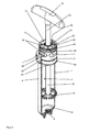
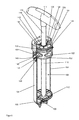
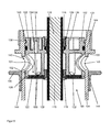
- FIGS. 1 to 3 show a first embodiment of the present invention and a first inventive vacuum mixing system, in which a bushing 1 is open by a substantially cylindrical discharge piston 2, and the FIG. 4 the same embodiment of the present invention or the first vacuum mixing system according to the invention in which the passage 1 is closed by the discharge piston 2.
- FIG. 1 an external perspective
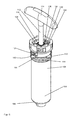
- FIG. 2 a partial perspective sectional view
- FIG. 3 a cross-sectional view
- FIG. 4 a cross-sectional view of a section of the vacuum mixing system according to the invention.
- the vacuum mixing system has a largely tubular cartridge 4 with an inner space 5.
- a cement powder (not shown) for producing a cement dough of two components is contained.
- the cartridge 4 is at the front (in the FIGS. 1 to 3 down and in FIG. 4 not visible) closed with a plate 6, in which an opening with an internal thread 8 is provided.
- a base plate (not shown) or a pedestal (not shown) or a dispensing tube (not shown) for applying the ready mixed cement dough may be mounted to the internal thread 8.
- a liquid container (not shown) with a liquid monomer as the second liquid component of the bone cement with the cartridge 4 via a line (not shown) is connected.
- the line opens into a nozzle on the base plate or the pedestal, wherein an external thread is provided on the nozzle, so that the cartridge 4 can be screwed with the internal thread 8 on the nozzle or screwed so that the line pressure-tight from the liquid container is connectable or connected via the line with the cartridge 4.
- a vacuum mixing system with such a base or such a base plate, such a conduit, such a nozzle and such a liquid container is for example from DE 10 2009 031 178 B3 or the US 8,757,866 B2 known, so that reference can be made to these patents for details.
- the cartridge 4 at the front side is initially closed to the outside by the cartridge 4 is screwed with the internal thread 8 on such a base or such a base plate of the vacuum mixing system.
- the cartridge 4 On the back (in the FIGS. 1 to 4 towards the top), the cartridge 4 is closed by the discharge piston 2.
- a passage in the discharge piston 2 extends a rod 10 which ends at the front in the interior 5 of the cartridge 4 in a mixing element 12 which has four radially extending in the direction of the wall of the cartridge 4 mixing blades.
- the rod 10 ends at the back (in the FIGS. 1 to 3 up and in FIG. 4 not seen) in a handle 14 with which the rod 10 can be moved manually.
- the rod 10 is rotatable about its axis and mounted in the axial direction (displaceable in the longitudinal direction) in the discharge piston 2.
- two bearing rings 16, 18 are provided in the discharge piston 2, which rest in fitting on the rod 10 and store the rod 10.
- the lower bearing ring 18 also serves to seal the interior 5 in order to prevent the escape of powder or cement paste from the interior 5.
- a seal 20 in the form of an O-ring made of rubber is also provided.
- the contents of the interior 5 can be mixed with the mixing element 12 manually.
- the passage 1 through the discharge piston 2 is covered at the front of the discharge piston 2 with a pore disk 22.
- the pore disk 22 prevents penetration of cement powder into the bushing 1 or an escape of cement powder from the vacuum mixing system.
- a circumferential seal 24 is provided in the form of an O-ring made of rubber, with which the space between the discharge piston 2 and the inner wall of the cartridge 4 is sealed and thus the inner space 5 can be closed off gas-tight and pressure-tight, when the discharge piston 2 is pushed deep enough or pushed into the cartridge 4, as for example in FIG. 4 is shown.
- the discharge piston 2 has a circumferential wiper lip 26, with which the cement dough is completely driven forward when discharging a ready mixed bone cement from the interior 5 through the opening in the plate 6 by means of the discharge piston 2, without the cement dough can push past the wiper lip 26 from the interior 5 over.
- the wiper lip 26 is deformed.
- the wiper lip 26 does not protrude, as in FIG. 4 shown in the wall of the cartridge 4, but is of its initial shape, as shown in FIG. 4 is shown, deformed accordingly. Due to the elastic force that occurs, the interior 5 is sealed with the wiper lip 26.
- the same principle of sealing, in the case against the rod 10, is also applied to the lower bearing ring 18.
- the rod 10 is guided by a sleeve 28 of the discharge piston 2. From the sleeve 28 radially four struts 30 extend as part of the discharge piston 2 in the direction of the outer circumference of the discharge piston 2. The struts 30 are used for mechanical stabilization and shaping of the discharge piston 2 and the storage of the pore disk 22.
- the plate 32 is part of the Austragskolbens 2 and executed in one piece with this.
- a vacuum feedthrough 34 is provided in the plate 32, which opens into a vacuum connection 36 in the form of a nozzle 36.
- a hose (not shown) can be plugged, which is connected to a vacuum source (not shown).
- a circumferential spring 38 is provided in the form of a ring 38, which is provided as a locking means 38 for locking the discharge piston 2 in the cartridge 4.
- a circumferential spring 38 is provided in the form of a ring 38, which is provided as a locking means 38 for locking the discharge piston 2 in the cartridge 4.
- two circumferential grooves 40, 42 or circumferential recesses 40, 42 are provided in the discharge piston 2, so that the discharge piston 2 can be locked in two different positions with respect to its longitudinal mobility in the cartridge 4.
- other, for example, manually deformable and therefore easily releasable locking means could be provided, without thereby limiting the invention.
- the bone cement powder is first filled.
- the discharge piston 2 is initially not yet inserted into the cartridge 4. Subsequently, the discharge piston 2 is inserted into the cartridge 4 until the spring 38 is locked with the lower groove 40.
- This first locked position of the discharge piston 2 is in the FIGS. 1 to 3 shown.
- the entire cartridge 4 or the entire vacuum mixing system can be disinfected or sterilized in a chamber by evacuating the air from the environment of the cartridge 4 or the vacuum mixing system and by filling the environment of the cartridge 4 or the vacuum mixing system with ethylene oxide.
- the discharge piston 2 is pushed deeper into the cartridge 4 until the spring 38 engages in the upper groove 42 and the discharge piston 2 is locked in a second position.
- the second locked position of the discharge piston 2 in the cartridge 4 is in FIG. 4 shown.
- the openings in the cylinder jacket of the Austragskolbens 2 are closed to the passages 1 in the second position.
- the seal 24 the interior 5 except for the Vacuum feedthrough 36 pressure-tight and gas-tight, by the seal 24 abuts against the inner walls of the cartridge 4.
- a hose is connected, which is connected to a vacuum source.
- the air is sucked out of the inner space 5.
- the interior 5 is pressure-tight except for the line connected to the plate 6 or the internal thread 8 and the liquid container, the interior 5 is evacuated.
- the line and the liquid container of the vacuum mixing system are closed to the outside gas-tight and pressure-tight. Through the line, the monomer is sucked from the liquid container into the inner space 5. There it mixes with the cement powder.
- the cement powder can be rotated with the monomer liquid with the mixing element 12 in the inner space 5 under vacuum and into it and pulled out of the rod 10 are mixed manually.
- the cartridge 4 is unscrewed from the base or the base plate and on the internal thread 8, a discharge pipe (not shown) is screwed.
- the discharge pipe may contain a static mixer.
- the rod 10 can be pulled out to the stop from the inner space 5, so that the mixing element 12 rests against the front side of the discharge piston 2.
- the rod 10 can be broken off with the handle 14 at a predetermined breaking point (not shown).
- the cartridge 4 can be inserted into a squeezing device (not shown) for driving the discharge piston 2 in the cartridge 4, or the discharge piston 2 is driven by means of a plunger (not shown).
- the discharge piston 2 can be unlocked from its second position, and the discharge piston 2 in the cartridge 4 is driven forward by the vacuum which is applied further, since outside of the cartridge 4 there is no vacuum but ambient pressure.
- the cement paste is expelled from the interior 5 of the cartridge 4 and applied via the discharge pipe.
- All parts of the vacuum mixing system are made of plastic by injection molding, wherein the seals 20, 24 are preferably made of rubber or other elastic plastic.
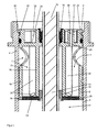
- FIGS. 5 to 8 show a second alternative embodiment of the present invention and a second inventive vacuum mixing system, in which a passage 101 is open by a substantially cylindrical discharge piston 102, and Figures 9 and 10 the same alternative embodiment of the present invention or the second vacuum mixing system according to the invention in which the passage 101 is closed by the discharge piston 102.
- FIG. 5 an external perspective
- FIG. 6 a partial perspective sectional view
- FIG. 7 a cross-sectional view
- FIG. 8 a cross-sectional view of a section
- FIG. 9 a partial side sectional view
- FIG. 10 a partial perspective sectional view of the vacuum mixing system.
- the structure of this alternative embodiment is substantially similar to the structure of the first embodiment.
- the vacuum mixing system has a largely tubular cartridge 104 with an interior 105.
- a cement powder (not shown) for producing a cement paste of two components is contained.
- the cartridge 104 is at the front (in the FIGS. 5 to 7 and 9 and 10 down and in FIG. 8 not visible) closed with a plate 106 in which an opening with an internal thread 108 is provided.
- a base plate (not shown) or a pedestal (not shown) or a dispensing tube (not shown) for applying the ready mixed cement dough.
- a liquid container (not shown) with a liquid monomer as the second liquid component of the bone cement is connected to the cartridge 104 via a conduit (not shown).
- the line opens into a nozzle on the base plate or the pedestal, wherein an external thread is provided on the nozzle, so that the cartridge 104 can be screwed with the internal thread 108 on the nozzle or screwed so that the line pressure-tight from the liquid container is connectable or connected via the line with the cartridge 104.
- a vacuum mixing system with such a base or such a base plate, such a conduit, such a nozzle and such a liquid container is for example from DE 10 2009 031 178 B3 or the US 8,757,866 B2 known, so that reference can be made to these patents for details.
- the cartridge 104 is closed at the front first to the outside by the cartridge 104 is screwed with the internal thread 108 on such a base or such a base plate of the vacuum mixing system.
- the cartridge 104 is closed by the discharge piston 102.
- a rod 110 extends, which ends at the front in the interior 105 of the cartridge 104 in a mixing element 112, which has four in the direction of the wall of the cartridge 104 radially réelleckenden mixing blades.
- the rod 110 terminates at the rear (in the FIGS. 5 to 7 and 9 and 10 up and in FIG. 8 not seen) in a handle 114, with which the rod 110 can be moved manually.
- the rod 110 is rotatable about its axis and mounted in the axial direction (displaceable in the longitudinal direction) in the discharge piston 102.
- two bearing rings 116, 118 are provided in the discharge piston 102, which bear in register on the rod 110 and store the rod 110.
- the lower bearing ring 118 also serves to seal the inner space 105 to prevent powder or cement paste from leaking out of the inner space 105.
- a seal 120 in the form of an O-ring made of rubber is also provided.
- the contents of the inner space 105 can be mixed with the mixing element 112 manually.
- the passage 101 through the discharge piston 102 is covered at the front of the Austragskolbens 102 with a pore disk 122.
- the pore disk 122 prevents penetration of cement powder into the passage 101 or leakage of cement powder from the vacuum mixing system.
- a circumferential seal 124 is provided in the form of a rubber O-ring, with the space between the Austragskolben 102 and the inner wall of the cartridge 104 is sealed and thus the inner space 105 is sealed gas-tight and pressure-tight, if the discharge piston 102 is pushed or inserted into the cartridge 104, as shown in FIGS FIGS. 5 to 10 is shown.
- the discharge piston 102 has a circumferential wiper lip 126, with the discharge of a ready mixed bone cement from the Interior 105 is driven by the opening in the plate 106 by means of the discharge piston 102 of the cement dough completely forward without the cement dough can push past the wiper lip 126 from the interior 105.
- the wiper lip 126 is deformed.
- the wiper lip 126 is deformed by its initial shape accordingly. Due to the elastic force occurring, the inner space 105 is sealed with the wiper lip 126.
- the same principle of sealing, in the case against the rod 110, is also applied to the lower bearing ring 118.
- the rod 110 is guided through a sleeve 128 of the discharge piston 102.
- struts 130 of the discharge piston 102 extend in the direction of the outer circumference of the discharge piston 102.
- the struts 130 are used for mechanical stabilization and shaping of the discharge piston 102 and the storage of the pore disk 122.
- On the back is the discharge piston 102 between the openings in the The outer surface of the discharge piston 102 for the passage 101 and the rear end of the discharge piston 102 (in the FIGS. 5 to 10 above) closed by a plate 132.
- the plate 132 is part of the Austragskolbens 102 and executed with this one-piece.
- a vacuum duct 134 is provided in the plate 132, which opens into a vacuum connection 136 in the form of a nozzle 136.
- a hose (not shown) can be plugged, which is connected to a vacuum source (not shown).
- a circumferential spring 138 is provided in the form of a ring 138, which is provided as a latching means 138 for locking the discharge piston 102 in the cartridge 104.
- a circumferential grooves 140 and a circumferential recess 140 is provided in the discharge piston 102, so that the discharge piston 102 can be locked in the cartridge 104 with regard to its mobility in the longitudinal direction.
- other, for example, manually deformable and thus easily releasable locking means could be provided, without thereby limiting the invention.
- an opening 143 is provided, which in the in the FIGS. 5 to 10 shown position of the Austragskolbens 102 is in register with the opening in the lateral surface of the Austragskolbens 102, the for performing 101 by the discharge piston 102 leads.
- an annular collar 144 is provided as the closure member 144.
- This collar 144 has an inner circumference that is just as large or slightly smaller than the outer circumference of the cartridge 104 so that the collar 144 fits snugly on the cartridge 104.
- projections 146 or handles 146 the sleeve 144 can be moved along the cylinder axis of the cartridge 104 and thereby close the openings 143 in the wall of the cartridge 104.
- the bone cement powder is filled.
- the discharge piston 102 is initially not inserted into the cartridge 104.
- the discharge piston 102 is inserted into the cartridge 104 until the spring 138 is locked with the groove 140.
- the sleeve 144 does not cover the opening 143 or openings 143.
- This open position is in the FIGS. 5 to 8 shown.
- the entire cartridge 104 or the entire vacuum mixing system in a chamber disinfected by evacuating the air from the environment of the cartridge 104 and the vacuum mixing system and by filling the environment of the cartridge 104 and the vacuum mixing system with ethylene oxide or be sterilized.
- the sleeve 144 is pushed over the opening 143.
- the openings 143 or the opening 143 in the wall of the cartridge 104 is closed to the passages 101.
- the seal 124 the inner space 105 is pressure-tight and gas-tightly closed except for the vacuum feedthrough 136, in that the seal 124 bears against the inner walls of the cartridge 104.
- a hose is connected, which is connected to a vacuum source.
- the air is sucked out of the inner space 105.
- the inner space 105 is evacuated. Due to the vacuum in the interior 105, the sleeve 144 is pressed or sucked onto the opening 143 and the opening 143 thereby effectively closed.
- the line and the liquid container of the vacuum mixing system are closed to the outside gas-tight and pressure-tight. Through the line, the monomer is sucked from the liquid container into the inner space 105. There it mixes with the cement powder.
- the cement powder may be mixed with the monomer liquid with the mixing element 112 in the interior space 105 by rotating it through and pushing it in and pulling it out of the bar 110 manually.
- the cartridge 104 is unscrewed from the base or the base plate and on the internal thread 108, a discharge tube (not shown) is screwed.
- the discharge pipe may contain a static mixer.
- the rod 110 can be pulled out to the stop from the inner space 105, so that the mixing element 112 rests against the front side of the discharge piston 102.
- the rod 110 can be broken off with the handle 114 at a predetermined breaking point (not shown).
- the cartridge 104 may be inserted into a squeezing device (not shown) for propelling the discharge piston 102 in the cartridge 104, or the discharge piston 102 is driven by means of a plunger (not shown).
- the discharge piston 102 can be unlocked from its locked position, and the discharge piston 102 in the cartridge 104 is driven forward by the further applied vacuum, since no vacuum but ambient pressure is present outside the cartridge 104.
- the cement dough is expelled from the inner space 105 of the cartridge 104 and applied via the discharge pipe.
- All parts of the vacuum mixing system are made of plastic by injection molding, wherein the seals 120, 124 are preferably made of rubber or other elastic plastic.
Abstract
Ein Vakuummischsystem zum Mischen von Polymethylmethacrylat-Knochenzement aufweisend zumindest eine Kartusche (4) mit einem evakuierbaren Innenraum (5) zum Mischen des Knochenzements, wobei der Innenraum (5) einen zylindrischen Hubraum umfasst, ein Mischelement (12), das im Innenraum (5) der Kartusche (4) beweglich angeordnet ist und das von außerhalb des Vakuummischsystems zum Mischen des Inhalts im Innenraum (5) der Kartusche (4) bedienbar ist und einen Austragskolben (2) mit einem zylindrischen Außenumfang, dessen erste Grundfläche eine Grundfläche des Innenraums (5) der Kartusche (4) begrenzt, der lösbar mit der Kartusche (4) zu arretieren oder arretiert ist und der im gelösten Zustand beweglich im zylindrischen Bereich des Innenraums (5) der Kartusche (4) ist, wobei in dem Austragskolben (2) eine gasdurchlässige und für Partikel undurchlässige Durchführung (1) angeordnet ist oder zwischen dem Austragskolben (2) und der Innenwand des Innenraums (5) eine Durchführung (1) gebildet ist, wobei die Durchführung (1) sich von einer Öffnung in der Mantelfläche des Austragskolbens (2) bis zu einer Öffnung in der ersten Grundfläche des Austragskolbens (2) erstreckt. Die Erfindung betrifft auch ein Verfahren zur Vermischung von Polymethylmethacrylat-Knochenzement in einer Kartusche (4) eines Vakuummischsystems.A vacuum mixing system for mixing polymethyl methacrylate bone cement comprising at least one cartridge (4) with an evacuable interior space (5) for mixing the bone cement, wherein the interior space (5) comprises a cylindrical displacement, a mixing element (12) which is located in the interior space (5). the cartridge (4) is movably arranged and that is operable from outside the vacuum mixing system for mixing the contents in the interior (5) of the cartridge (4) and a discharge piston (2) with a cylindrical outer periphery whose first base surface has a base surface of the interior (5 ) of the cartridge (4) which is releasably locked to the cartridge (4) or locked and which is in the dissolved state movable in the cylindrical portion of the interior (5) of the cartridge (4), wherein in the discharge piston (2) has a gas-permeable and impermeable to particles passage (1) is arranged or between the discharge piston (2) and the inner wall of the inner space (5) has a passage (1) is formed, wherein the passage (1) extending from an opening in the lateral surface of the Austragskolbens (2) to an opening in the first base of the Austragskolbens (2). The invention also relates to a method for mixing polymethyl methacrylate bone cement in a cartridge (4) of a vacuum mixing system.
Description
Die Erfindung betrifft ein Vakuummischsystem zum Mischen von Polymethylmethacrylat-Zement (PMMA-Zement) aus zwei Ausgangskomponenten, insbesondere zum Mischen eines medizinischen Knochenzements, und zur Lagerung der Ausgangskomponenten.The invention relates to a vacuum mixing system for mixing polymethyl methacrylate cement (PMMA cement) from two starting components, in particular for mixing a medical bone cement, and for storing the starting components.
Die Erfindung betrifft ferner ein Verfahren zum Mischen von Polymethylmethacrylat-Knochenzement.The invention further relates to a method for mixing polymethyl methacrylate bone cement.
Gegenstand der Erfindung ist somit ein Vakuummischsystem für die Lagerung, Vermischung und gegebenenfalls auch das Austragen von Polymethylmethacrylat-Knochenzement.The invention thus provides a vacuum mixing system for the storage, mixing and optionally also the discharge of polymethyl methacrylate bone cement.
Polymethylmethacrylat-(PMMA)-Knochenzemente gehen auf die grundlegenden Arbeiten von Sir Charnley zurück. PMMA-Knochenzemente bestehen aus einer flüssigen Monomerkomponente und einer Pulverkomponente. Die Monomerkomponente enthält im Allgemeinen das Monomer Methylmethacrylat und einen darin gelösten Aktivator (N,N-Dimethyl-p-toluidin). Die Pulverkomponente, auch als Knochenzementpulver bezeichnet, weist ein oder mehrere Polymere, einen Röntgenopaker und den Initiator Dibenzoylperoxid auf. Die Polymere der Pulverkomponente werden auf Basis von Methylmethacrylat und Comonomeren, wie Styren, Methylacrylat oder ähnlichen Monomeren durch Polymerisation, vorzugsweise Suspensionspolymerisation, hergestellt. Beim Vermischen der Pulverkomponente mit der Monomerkomponente entsteht durch Quellung der Polymere der Pulverkomponente im Methylmethacrylat ein plastisch verformbarer Teig, der eigentliche Knochenzement. Beim Vermischen der Pulverkomponente mit der Monomerkomponente reagiert der Aktivator N,N-Dimethyl-p-toluidin mit Dibenzoylperoxid unter Bildung von Radikalen. Die gebildeten Radikale initiieren die radikalische Polymerisation des Methylmethacrylats. Mit fortschreitender Polymerisation des Methylmethacrylats erhöht sich die Viskosität des Zementteigs, bis dieser erstarrt.Polymethylmethacrylate (PMMA) bone cements go back to the fundamental work of Sir Charnley. PMMA bone cements consist of a liquid monomer component and a powder component. The monomer component generally contains the monomer methyl methacrylate and an activator (N, N-dimethyl-p-toluidine) dissolved therein. The powder component, also referred to as bone cement powder, has one or more polymers, an X-ray opaque and the initiator dibenzoyl peroxide. The polymers of the powder component are prepared based on methyl methacrylate and comonomers such as styrene, methyl acrylate or similar monomers by polymerization, preferably suspension polymerization. When the powder component is mixed with the monomer component, swelling of the polymers of the powder component in methyl methacrylate produces a plastically deformable dough, the actual bone cement. Upon mixing the powder component with the monomer component, the activator reacts N, N-dimethyl-p-toluidine with dibenzoyl peroxide to form radicals. The radicals formed initiate the radical polymerization of the methyl methacrylate. As the polymerization of methyl methacrylate progresses, the viscosity of the cement dough increases until it solidifies.
Das am häufigsten in Polymethylmethacrylat-Knochenzementen verwendete Monomer ist Methylmethacrylat. Redoxinitiatorsysteme bestehen üblicherweise aus Peroxiden, Beschleunigern sowie gegebenenfalls geeigneten Reduktionsmitteln. Eine Radikalbildung erfolgt nur dann, wenn alle Bestandteile der Redoxinitiatorsysteme zusammenwirken. Deshalb werden die Bestandteile des Redoxinitiatorsystems in den separaten Ausgangskomponenten so angeordnet, dass diese keine radikalische Polymerisation auslösen können. Die Ausgangskomponenten sind bei geeigneter Zusammensetzung lagerstabil. Erst bei Vermischung der beiden Ausgangskomponenten zu einem Zementteig reagieren die zuvor getrennt in den beiden Pasten, Flüssigkeiten oder Pulvern gelagerten Bestandteile des Redoxinitiatorsystems, wobei Radikale gebildet werden, welche die radikalische Polymerisation des wenigstens einen Monomers auslösen. Die radikalische Polymerisation führt dann unter Verbrauch des Monomers zu Bildung von Polymeren, wobei der Zementteig aushärtet.The monomer most commonly used in polymethyl methacrylate bone cements is methyl methacrylate. Redox initiator systems usually consist of Peroxides, accelerators and, where appropriate, suitable reducing agents. A radical formation takes place only when all components of the redox initiator systems interact. Therefore, the components of the redox initiator system are placed in the separate starting components so that they can not initiate radical polymerization. The starting components are storage stable with a suitable composition. It is only when the two starting components are mixed to form a cement dough that the components of the redox initiator system previously stored separately in the two pastes, liquids or powders react, forming radicals which trigger the radical polymerization of the at least one monomer. The radical polymerization then leads to the formation of polymers with consumption of the monomer, wherein the cement paste hardens.
PMMA-Knochenzemente können in geeigneten Mischbechern mit Hilfe von Spateln durch Vermischen des Zementpulvers mit der Monomerflüssigkeit vermischt werden. Nachteilig ist an dieser Vorgehensweise, dass Lufteinschlüsse im gebildeten Zementteig vorhanden sein können, die später eine Destabilisierung des Knochenzements verursachen können. Aus diesem Grund wird das Vermischen von Knochenzementpulver mit der Monomerflüssigkeit in Vakuummischsystemen bevorzugt, weil durch Mischen im Vakuum Lufteinschlüsse aus dem Zementteig weitgehend entfernt werden und damit eine optimale Zementqualität erreicht wird. Im Vakuum gemischte Knochenzemente haben eine deutlich verringerte Porosität und zeigen daher verbesserte mechanische Eigenschaften. Es wurden eine Vielzahl von Vakuum-Zementiersystemen offen gelegt, von denen exemplarisch folgende genannt sind:
Eine Weiterentwicklung in der Zementiertechnik stellen Zementiersysteme dar, in denen sowohl das Zementpulver als auch die Monomerflüssigkeit bereits in separaten Kompartimenten der Mischsysteme verpackt sind und die erst unmittelbar vor der Zementapplikation im Zementiersystem miteinander vermischt werden. Solche Full-Prepacked-Mischsysteme wurden mit der
Die Aufgabe der Erfindung besteht also darin, die Nachteile des Stands der Technik zu überwinden. Insbesondere soll ein einfach aufgebautes und kostengünstig zu fertigendes, geschlossenes Vakuummischsystem für Polymethylmethacrylat-Knochenzement und ein Verfahren zum Mischen eines Zwei-Komponenten-Knochenzements unter Vakuum bereitgestellt werden. Dabei soll auch eine alternative Lösung bereitgestellt werden. Bevorzugt soll das Vakuummischsystem mit möglichst wenigen beweglichen Teilen auskommen. Insbesondere soll auch ein einfacher Aufbau des Austragskolbens ermöglicht werden. Die Bedienung des Vakuummischsystems soll einfach und intuitiv sein.The object of the invention is therefore to overcome the disadvantages of the prior art. In particular, a simple and inexpensive to manufacture, closed vacuum mixing system for polymethylmethacrylate bone cement and a method for mixing a two-component bone cement under vacuum to be provided. An alternative solution should also be provided. Preferably, the vacuum mixing system should make do with as few moving parts as possible. In particular, a simple construction of the discharge piston is to be made possible. The operation of the vacuum mixing system should be simple and intuitive.
Dieses Vakuummischsystem soll eine Zement-Kartusche enthalten, in der das Zementpulver gelagert ist, sowie einen davon separaten Vorratsbehälter, in dem sich die Monomerflüssigkeit befindet. Die Monomerflüssigkeit wird dadurch getrennt von dem Zementpulver gelagert. Vor und während der Vermischung der beiden Zementkomponenten, dem Zementpulver mit der Monomerflüssigkeit, soll ein Kontakt der medizinischen Anwender mit diesen Komponenten ausgeschlossen sein. Die Öffnung des Vorratsbehälters und der Transfer des Monomers müssen daher in einem geschlossenen System erfolgen. Das Zementpulver darf ebenfalls nicht in Kontakt zum medizinischen Anwender kommen. Bei einer Ethylenoxid-Sterilisation des Vakuummischsystems ist es unumgänglich, dass das Ethylenoxid in das in der Zement-Kartusche befindliche Zementpulver eindringt und anschließend wieder aus diesem austritt. Für diesen Gasaustausch ist eine Öffnung in der Kartusche zur umgebenden Atmosphäre mit einer großen Gasaustauschfläche erforderlich. Dabei darf jedoch das Zementpulver nicht aus der Zement-Kartusche austreten. Das bedeutet, das Vakuummischsystem muss so beschaffen sein, dass ein Gasaustauch möglich ist, ohne dass das Zementpulver austreten kann. Weiterhin muss die Zement-Kartusche während des Mischvorgangs vakuumdicht verschlossen werden können. Die Erfindung hat daher ferner die Aufgabe, eine Vakuummischvorrichtung bereitzustellen, welche den Widerspruch zwischen der maximalen Gasdurchlässigkeit der Zement-Kartusche zum Gasaustausch während der Ethylenoxid-Sterilisation bei gleichzeitiger Verhinderung des Austritts des Zementpulvers und der Vakuum-Dichtigkeit der Zement-Kartusche während des Vermischungsvorganges löst. Das zu entwickelnde Vakuummischsystem soll möglichst aus üblichen thermoplastischen Kunststoffen durch Spritzgießen hergestellt werden können und damit für Einmalanwendungen geeignet sein.This vacuum mixing system is intended to contain a cement cartridge in which the cement powder is stored, as well as a separate reservoir in which the monomer liquid is located. The monomer liquid is thereby stored separately from the cement powder. Before and during the mixing of the two cement components, the cement powder with the monomer liquid, contact between the medical user and these components should be excluded. The opening of the reservoir and the transfer of the monomer must therefore be done in a closed system. The cement powder must also not come into contact with the medical user. In the case of ethylene oxide sterilization of the vacuum mixing system, it is imperative that the ethylene oxide penetrate into the cement powder contained in the cement cartridge and then exit from it again. This gas exchange requires an opening in the cartridge to the surrounding atmosphere with a large gas exchange area. However, the cement powder must not escape from the cement cartridge. This means that the vacuum mixing system must be designed so that gas exchange is possible without the cement powder escaping. Furthermore, the cement cartridge must be able to be closed vacuum-tight during the mixing process. It is another object of the present invention to provide a vacuum mixing apparatus which resolves the contradiction between the maximum gas permeability of the cement cartridge for gas exchange during the ethylene oxide sterilization while preventing the escape of the cement powder and the vacuum seal of the cement cartridge during the mixing operation , The vacuum mixing system to be developed should as far as possible be made from conventional thermoplastics by injection molding and thus be suitable for single use.
Des Weiteren soll eine kostengünstig zu fertigende und zuverlässig funktionierende Vorrichtung zum Mischen eines medizinischen Zements und gegebenenfalls zur Lagerung der Ausgangskomponenten sowie ein Verfahren zum Mischen des Knochenzements gefunden werden, bei dem eine möglichst einfache Bedienung zum Mischen der Ausgangskomponenten angewendet werden kann, möglichst ohne dass Lufteinschlüsse in dem Zementteig entstehen können.Furthermore, a cost-effective and reliably functioning device for mixing a medical cement and optionally for storing the starting components and a method for mixing the bone cement is to be found, in which the simplest possible operation for mixing the starting components can be used, if possible without air pockets can arise in the cement dough.
Die Hauptkomponente des Polymethylmethacrylat-Knochenzements soll ein Pulver sein und die zweite Komponente soll in Form einer Flüssigkeit vorliegen. Die beiden Ausgangskomponenten des Knochenzements sollen bevorzugt in dem Vakuummischsystem getrennt gelagert werden können und durch Anwendung der Vorrichtung sicher zusammengeführt werden können.The main component of the polymethylmethacrylate bone cement is to be a powder and the second component should be in the form of a liquid. The two starting components of the bone cement are preferably to be stored separately in the vacuum mixing system and can be safely combined by using the device.
Die Aufgaben der Erfindung werden gelöst durch ein Vakuummischsystem zum Mischen von Polymethylmethacrylat-Knochenzement aufweisend zumindest eine Kartusche mit einem evakuierbaren Innenraum zum Mischen des Knochenzements, wobei der Innenraum einen zylindrischen Hubraum umfasst, ein Mischelement, das im Innenraum der Kartusche beweglich angeordnet ist und das von außerhalb des Vakuummischsystems zum Mischen des Inhalts im Innenraum der Kartusche bedienbar ist und einen Austragskolben mit einem zylindrischen Außenumfang, dessen erste Grundfläche eine Grundfläche des Innenraums der Kartusche begrenzt, der lösbar mit der Kartusche zu arretieren oder arretiert ist und der im gelösten Zustand beweglich im zylindrischen Bereich des Innenraums der Kartusche ist, wobei in dem Austragskolben eine gasdurchlässige und für Partikel undurchlässige Durchführung angeordnet ist oder zwischen dem Austragskolben und der Innenwand des Innenraums eine Durchführung gebildet ist, wobei die Durchführung sich von einer Öffnung in der Mantelfläche des Austragskolbens bis zu einer Öffnung in der ersten Grundfläche des Austragskolbens erstreckt.The objects of the invention are achieved by a vacuum mixing system for mixing polymethyl methacrylate bone cement comprising at least one cartridge with an evacuable interior for mixing the bone cement, wherein the interior comprises a cylindrical displacement, a mixing element which is movably arranged in the interior of the cartridge and that of outside the vacuum mixing system for mixing the contents in the interior of the cartridge is operable and a discharge piston having a cylindrical outer periphery whose first base defines a bottom surface of the interior of the cartridge, which is releasably locked to the cartridge or locked and in the dissolved state movable in the cylindrical Is the region of the interior of the cartridge, wherein in the Austragskolben a gas-permeable and impermeable to particles passage is arranged or formed between the discharge piston and the inner wall of the interior of a passage, wherein the through leads from one Opening in the lateral surface of the Austragskolbens extends to an opening in the first base of the Austragskolbens.
Ein Zylinder im Sinne der vorliegenden Erfindung ist, wie auch nach der allgemeinen Definition, ein von zwei parallelen, ebenen, kongruenten Flächen (Grund- und Deckfläche) und einer Mantelfläche beziehungsweise Zylinderfläche begrenzter Körper, wobei die Mantelfläche von parallelen Geraden gebildet wird. Das heißt, der Zylinder entsteht durch Verschiebung einer ebenen Fläche entlang einer Geraden, die nicht in dieser Ebene liegt. Die Höhe des Zylinders ist gegeben durch den Abstand der beiden Ebenen, in denen Grund- und Deckfläche liegen.A cylinder according to the present invention, as well as the general definition, one of two parallel, flat, congruent surfaces (top and top surface) and a lateral surface or cylindrical surface limited body, wherein the lateral surface is formed by parallel straight lines. That is, the cylinder is created by shifting a flat surface along a straight line that is not in that plane. The height of the cylinder is given by the distance between the two planes, in which the base and top surface are.
Sind die Geraden senkrecht zu Grund- und Deckfläche, spricht man von einem geraden Zylinder. Die gerade zylindrische Geometrie des Innenraums ist erfindungsgemäß bevorzugt, bezieht sich aber besonders bevorzugt nur auf einen oder mehrere Teilbereich des gesamten Innenraums der Kartusche. Ein gerader Kreiszylinder stellt im Sinne der vorliegenden Erfindung also nur einen Spezialfall einer zylindrischen Geometrie dar, der aber wegen der besonders einfachen Möglichkeiten zu dessen Herstellung eine besonders bevorzugte Symmetrie ist.If the straight lines are perpendicular to the base and top surfaces, this is called a straight cylinder. The straight cylindrical geometry of the interior is preferred according to the invention, but particularly preferably relates only to one or more subregions of the entire interior of the cartridge. A straight circular cylinder represents in the context of the present invention, therefore, only a special case of a cylindrical geometry, but because of the particularly simple ways to produce it is a particularly preferred symmetry.
Unter einem zylindrischen Außenumfang des Austragskolbens ist vorliegend zu verstehen, dass der Austragskolben zumindest in einem Abschnitt einen zylindrischen Umfang aufweist, der die maximale radiale Ausdehnung bezüglich des Austragskolbens bezogen auf die zylindrische Geometrie des zylindrischen Abschnitts bildet. Der Austragskolben kann bereichsweise auch eine andere Form als die zylindrische Form aufweisen, insbesondere können zumindest ein Dichtungsring, zumindest ein Rastmittel oder Gegenrastmittel und eine Abstreiflippe zusätzlich zu der Öffnung in der Mantelfläche vorhanden sein. Bevorzugt dichtet der Austragskolben den zylindrischen Hubraum mit dem zylindrischen Außenumfang bis auf die Durchführung und einen Vakuumanschluss ab, wenn der zylindrische Außenumfang innerhalb des Hubraums angeordnet ist.In the present case, a cylindrical outer circumference of the discharge piston is to be understood as meaning that the discharge piston has, at least in one section, a cylindrical circumference which forms the maximum radial extent with respect to the discharge piston relative to the cylindrical geometry of the cylindrical section. The discharge piston may partially have a different shape than the cylindrical shape, in particular at least one sealing ring, at least one locking means or counter-locking means and a wiper lip may be present in addition to the opening in the lateral surface. Preferably, the discharge piston seals the cylindrical displacement with the cylindrical outer circumference except for the passage and a vacuum connection when the cylindrical outer circumference is arranged within the displacement.
Wenn die Durchführung zwischen dem Austragskolben und der Innenwand des Innenraums eine Durchführung gebildet ist, kann beispielsweise in dem Zylindermantel des Austragskolbens und/oder der Innenwand des Innenraums eine Rinne vorgesehen sein, die die Durchführung begrenzen. Die Durchführung bezieht sich dabei auf den an den Innenwänden des Innenraums anliegenden Austragskolben. Die Durchführung und die Öffnungen können daher auch durch die Bereiche definiert sein, an denen der Austragskolben nicht an den Innenwänden des Innenraums anliegt, was beispielsweise eben auch durch eine Vertiefung, einer Rille oder Rinne in der ansonsten zylindrischen Innenwand der Kartusche definiert werden. Bevorzugt ist die Durchführung jedoch in dem Austragskolben angeordnet.If the passage between the discharge piston and the inner wall of the inner space is formed a passage, for example, in the cylinder jacket of the Austragskolbens and / or the inner wall of the interior, a groove may be provided which limit the implementation. The implementation refers to the voltage applied to the inner walls of the interior discharge piston. The passage and the openings can therefore also be defined by the areas where the Discharge piston does not abut against the inner walls of the interior, which, for example, just by a depression, a groove or groove in the otherwise cylindrical inner wall of the cartridge are defined. Preferably, however, the passage is arranged in the discharge piston.
Der Begriff Unterdruck bezieht sich vorliegend immer auf einen relativ zur umgebenden Atmosphäre bezogenen Druck, der kleiner ist als der umgebende Atmosphärendruck.The term negative pressure in the present case always refers to a relative to the surrounding atmosphere related pressure, which is smaller than the surrounding atmospheric pressure.
Besonders bevorzugt ist der Knochenzement ein PMMA-Knochenzement. Der Polymethylmethacrylat-Knochenzement (PMMA-Knochenzement) wird bevorzugt aus zumindest zwei Komponenten gemischt beziehungsweise ist aus zumindest zwei Komponenten herstellbar. Besonders bevorzugt ist eine Komponente flüssig und eine andere Komponente pulverförmig.The bone cement is particularly preferably a PMMA bone cement. The polymethylmethacrylate bone cement (PMMA bone cement) is preferably mixed from at least two components or can be produced from at least two components. Particularly preferably, one component is liquid and another component is powdery.
Auch im zylindrischen Bereich des Hubraums des Austragskolbens können Vertiefungen, wie eine Nut, oder Vorsprünge, wie eine Feder oder ein umlaufender Ring, angeordnet sein, so dass die zylindrische Symmetrie bereichsweise durchbrochen sein kann. Hierdurch kann in dem zylindrischen Bereich eine Rastung für ein Rastmittel am Austragskolben realisiert werden. Das Gleiche gilt dementsprechend für den zylindrischen Außenumfang des Austragskolbens.Also in the cylindrical region of the displacement of the Austragskolbens depressions, such as a groove, or projections, such as a spring or a circumferential ring may be arranged so that the cylindrical symmetry may be partially broken. As a result, a detent for a locking means on the discharge piston can be realized in the cylindrical region. The same applies accordingly to the cylindrical outer circumference of the discharge piston.
Das Vakuummischsystem ist bevorzugt nach außen Gasdicht ausgebildet beziehungsweise gasdicht abdichtbar.The vacuum mixing system is preferably formed gas-tight to the outside or gas-tight sealable.
Mit einer Weiterbildung der Erfindung wird vorgeschlagen, dass der Austragskolben wenigstens eine umlaufende Dichtung aufweist, die den Innenraum der Kartusche nach außen abdichtet, wobei bevorzugt wenigstens eine umlaufende Dichtung zwischen einer zweiten Grundfläche des Austragskolbens, die der ersten Grundfläche des Austragskolbens gegenüberliegt, und der Öffnung in der Mantelfläche des Austragskolbens angeordnet ist.In a further development of the invention, it is proposed that the discharge piston has at least one circumferential seal which seals the interior of the cartridge to the outside, wherein preferably at least one peripheral seal between a second base of the discharge piston, which is opposite to the first base of the discharge piston, and the opening is arranged in the lateral surface of the discharge piston.
Hierdurch wird eine bessere Vakuumstabilität des Innenraums erreicht. Dadurch kann der Unterdruck oder das Vakuum im Innenraum länger aufrechterhalten werden.As a result, a better vacuum stability of the interior is achieved. As a result, the negative pressure or the vacuum in the interior can be maintained longer.
Es kann bei einer Ausführungsvariante der vorliegenden Erfindung vorgesehen sein, dass eine der Mantelflächen der Kartuschenwandung der Kartusche eine Öffnung aufweist, die mit der Öffnung in der Mantelfläche des Austragskolbens in einer geöffneten Position des Austragskolbens in Überdeckung liegt und durch die der Innenraum gasdurchlässig mit der Umgebung des Vakuummischsystems verbunden oder verbindbar ist.It may be provided in one embodiment of the present invention that one of the lateral surfaces of the cartridge wall of the cartridge has an opening which is in coincidence with the opening in the lateral surface of the Austragskolbens in an open position of the Austragskolbens and by the Interior gas-permeable connected or connectable to the environment of the vacuum mixing system.
Hierdurch kann der Austragskolben tief und stabil in der Kartusche eingesetzt bleiben. Dadurch kann eine bessere Stabilität des Vakuummischsystems erreicht werden und der Austragskolben kann weniger leicht verkanten und kann etwas kürzer ausgeführt werden.This allows the discharge piston to remain deep and stable in the cartridge. As a result, a better stability of the vacuum mixing system can be achieved and the discharge piston can tilt less easily and can be made somewhat shorter.
Dabei kann vorgesehen sein, dass an der Außenwand der Kartusche ein Verschlusselement angeordnet ist, mit dem die Öffnung in der Wandung der Kartusche verschließbar ist, bevorzugt ein in axialer Richtung der Kartusche verschiebbares Verschlusselement an der Außenwand der Kartusche angeordnet ist.It can be provided that on the outer wall of the cartridge, a closure element is arranged, with which the opening in the wall of the cartridge is closable, preferably a displaceable in the axial direction of the cartridge closure element is arranged on the outer wall of the cartridge.
Hierdurch muss die Öffnung in der Kartuschenwandung nicht vom Austragskolben oder zumindest nicht vom Austragskolben alleine verschlossen werden. Zudem zieht sich ein auf der Kartuschenwandung außen angeordnetes Verschlusselement unter der Einwirkung eines Vakuums im Inneren des Innenraums von alleine zu und dichtet die Öffnung in der Kartuschenwandung ab. Alternativ kann der Austragskolben auch so gegen die Öffnung der Kartuschenwandung verdreht und/oder verschoben werden, dass die Durchführung nicht mehr in Überdeckung mit der Öffnung in der Kartuschenwandung liegt und dadurch die Durchführung im oder am Austragskolben verschlossen ist beziehungsweise verschließbar ist.As a result, the opening in the cartridge wall does not have to be closed by the discharge piston or at least not by the discharge piston alone. In addition, a closing element arranged on the exterior of the cartridge wall, under the influence of a vacuum inside the interior, contracts by itself and seals the opening in the cartridge wall. Alternatively, the discharge piston can also be rotated and / or displaced against the opening of the cartridge wall in such a way that the passage is no longer in register with the opening in the cartridge wall and thus the passage in or on the discharge piston is closed or can be closed.
Bei der Ausführung mit einem Verschlusselement auf der Außenwandung der Kartusche kann wiederum vorgesehen sein, dass das Verschlusselement eine umlaufende Manschette ist, die in Passung auf der Außenwand der Kartusche anliegt und in axialer Richtung der Kartusche verschiebbar ist, um die Öffnung in der Wandung der Kartusche abzudecken und dadurch zu verschließen, wobei bevorzugt an der Manschette wenigstens ein Griffstück befestigt ist, das zum manuellen Verschieben der Manschette auf der Außenwand der Kartusche vorgesehen ist.In the embodiment with a closure element on the outer wall of the cartridge may in turn be provided that the closure element is a circumferential sleeve, which fits in fitting on the outer wall of the cartridge and is displaceable in the axial direction of the cartridge to the opening in the wall of the cartridge cover and thereby close, wherein preferably at least one handle is attached to the sleeve, which is provided for manually displacing the sleeve on the outer wall of the cartridge.
Die Manschette muss nicht vollständig umlaufend sein, sondern kann unterbrochen sein, das heißt eine axiale Durchbrechung aufweisen. Die Manschette kann dazu als Ringsegment oder Rohrsegment ausgebildet sein, das die Außenwand der Kartusche um zumindest 50% umschließt, bevorzugt um zumindest 60% umschließt, besonders bevorzugt um zumindest 75% umschließt. Der Innendurchmesser der Manschette ist bevorzugt gleich oder kleiner dem Außendurchmesser der Kartusche. Diese Ausführung ist besonders einfach zu bedienen und kostengünstig zu realisieren.The sleeve does not have to be completely circumferential, but can be interrupted, that is to say have an axial opening. The sleeve can be designed as a ring segment or tube segment, which encloses the outer wall of the cartridge by at least 50%, preferably by at least 60% encloses, more preferably by at least 75% encloses. The inner diameter of the sleeve is preferably equal to or less than the outer diameter of the cartridge. This design is particularly easy to use and inexpensive to implement.
Bei einer alternativen Ausführung der vorliegenden Erfindung kann vorgesehen sein, dass der Austragskolben in einer ersten arretierbaren Stellung aus der Kartusche herausragt, so dass die Öffnung in der Mantelfläche des Austragskolbens offen liegt und dass der Austragskolben in einer zweiten arretierbaren Stellung tiefer in dem Innenraum der Kartusche angeordnet ist, so dass die Öffnung in der Mantelfläche des Austragskolbens durch die Innenwand der Kartusche verschlossen ist.In an alternative embodiment of the present invention can be provided that the discharge piston protrudes in a first lockable position from the cartridge, so that the opening in the lateral surface of the discharge piston is open and that the discharge piston in a second lockable position deeper in the interior of the cartridge is arranged, so that the opening in the lateral surface of the Austragskolbens is closed by the inner wall of the cartridge.
Diese Ausführung hat den Vorteil, dass die Kartuschenwand ohne Öffnung aufgebaut werden kann.This embodiment has the advantage that the cartridge wall can be constructed without an opening.
Dabei kann vorgesehen sein, dass zwischen der Öffnung in der Mantelfläche des Austragskolbens und der zweiten Grundfläche des Austragskolbens, die der ersten Grundfläche des Austragskolbens gegenüberliegt, ein umlaufendes Dichtungselement angeordnet ist.It can be provided that between the opening in the lateral surface of the Austragskolbens and the second base of the Austragskolbens, which is opposite to the first base of the Austragskolbens, a circumferential sealing element is arranged.
Hierdurch wird die Abdichtung des Innenraums der Kartusche in den verschiedenen Stellungen des Austragskolbens sichergestellt.As a result, the sealing of the interior of the cartridge is ensured in the different positions of the discharge piston.
Bevorzugte Ausführungsformen der Erfindung können sich dadurch auszeichnen, dass in der Durchführung und/oder an der Öffnung zur Durchführung in der Mantelfläche des Austragskolbens und/oder an der Öffnung zur Durchführung in der ersten Grundfläche des Austragskolbens ein gasdurchlässiger Partikelfilter, insbesondere ein Porenfilter, angeordnet ist, wobei bevorzugt der gasdurchlässige Partikelfilter für Partikel mit einem Durchmesser von über 1 µm undurchlässig ist, besonders bevorzugt für Partikel mit einem Durchmesser von über 5 µm undurchlässig ist.Preferred embodiments of the invention can be characterized in that a gas-permeable particle filter, in particular a pore filter, is arranged in the passage and / or at the opening for passage in the lateral surface of the discharge piston and / or at the opening for passage in the first base surface of the discharge piston , wherein preferably the gas-permeable particle filter for particles with a diameter of about 1 micron is impermeable, particularly preferably for particles with a diameter of about 5 microns is impermeable.
Hierdurch wird sichergestellt, dass das Zementpulver aus dem Innenraum der Kartusche in dem Innenraum verbleibt, während Gase aus dem Innenraum evakuiert werden können und andere Gase, wie beispielsweise Ethylenoxid, eingefüllt werden können.This ensures that the cement powder from the interior of the cartridge in the interior remains, while gases can be evacuated from the interior and other gases, such as ethylene oxide, can be filled.
Gemäß einer Weiterbildung der vorliegenden Erfindung wird vorgeschlagen, dass der Austragskolben an seiner aus dem Inneren der Kartusche weisenden Seite bis auf eine Vakuumdurchführung gasdicht ist.According to one embodiment of the present invention, it is proposed that the discharge piston is gas-tight at its side facing away from the interior of the cartridge, except for a vacuum feed-through.
Mit der Vakuumdurchführung, kann dann ein Vakuum im Inneren der Kartusche gezogen werden, nachdem die Durchführung verschlossen wurde.With the vacuum feedthrough, a vacuum can then be drawn inside the cartridge after the bushing has been closed.
Ferner kann vorgesehen sein, dass der Austragskolben an der ersten Grundfläche eine gasdurchlässige Porenscheibe aufweist, die durch eine Verrippung gestützt wird. Hierdurch kann die Porenscheibe mechanisch stabilisiert werden.Furthermore, it can be provided that the discharge piston has a gas-permeable pore disk on the first base surface, which is supported by a ribbing. As a result, the pore plate can be mechanically stabilized.
Gemäß einer weiteren Ausführung kann vorgesehen sein, dass der Austragskolben axial in die Kartusche eindrückbar ist, um einen aus einem Knochenzementpulver und einer Monomerflüssigkeit gemischten Knochenzementteig durch eine Austragsöffnung an einem dem Austragskolben gegenüberliegenden Ende der Kartusche auszutragen, wobei bevorzugt der Austragskolben nach dem Lösen einer Arretierung axial in die Kartusche eindrückbar ist.According to a further embodiment it can be provided that the discharge piston can be pushed axially into the cartridge to discharge a bone cement dough mixed from a bone cement powder and a monomer liquid through a discharge opening at an end of the cartridge opposite the discharge piston, the discharge piston preferably after release of a lock axially pressed into the cartridge.
Dadurch wird sichergestellt, dass der Austragskolben nach dem Sterilisieren des Inhalts des Innenraums und nach dem Mischen der Knochenzementkomponenten unter Vakuum zu seinem eigentlichen Zweck, nämlich dem Austragen des Zementteigs aus der Kartusche verwendet werden kann.This ensures that the discharge flask, after sterilizing the contents of the interior and after mixing the bone cement components under vacuum, can be used for its actual purpose of discharging the cement paste from the cartridge.
Mit der Erfindung wird auch vorgeschlagen, dass eine Austragsöffnung der Kartusche ein Anschlussmittel, insbesondere ein Anschlussgewinde, aufweist.The invention also proposes that a discharge opening of the cartridge has a connection means, in particular a connection thread.
Besonders geeignet ist als Anschlussmittel ein Anschlussgewinde in Form eines Innengewindes oder Außengewindes. Das Anschlussgewinde kann zum einen zum Schließen eines Applikationsrohrs verwendet werden und zum anderen zum Befestigen der Kartusche an einem Standfuß oder an einem Basiselement verwendet werden.Particularly suitable as connection means is a connection thread in the form of an internal thread or external thread. The connection thread can firstly be used for closing an application tube and secondly be used for fastening the cartridge to a base or to a base element.
Bevorzugt kann auch vorgesehen sein, dass das Mischelement an einer Stange angeordnet ist, die durch einen gasdichten Durchgang ins Innere der Kartusche geführt ist, und sich das Mischelement durch hineinschieben und herausziehen aus der Kartusche und durch Drehen in der Kartusche bewegen lässt, wobei bevorzugt die Stange eine Sollbruchstelle aufweist, an der die Stange, wenn sie aus der Kartusche herausgezogen ist, nahe dem Durchgang abzubrechen ist.Preferably, it can also be provided that the mixing element is arranged on a rod which is guided through a gas-tight passage into the interior of the cartridge, and can move the mixing element by pushing in and out of the cartridge and by rotating in the cartridge, preferably the Rod has a predetermined breaking point at which the rod when it is pulled out of the cartridge is to break off near the passage.
Mit der durchgeführten Stange kann das Mischelement besonders einfach von außen bedient werden. Bevorzugt ist die Stange durch einen gasdichten Durchgang in dem Austragskolben in das Innere der Kartusche geführt.With the rod made, the mixing element can be very easily operated from the outside. Preferably, the rod is guided through a gas-tight passage in the discharge piston into the interior of the cartridge.
Bevorzugte Ausführungsformen können sich dadurch auszeichnen, dass das Vakuummischsystem einen Vorratsbehälter für eine Monomerflüssigkeit aufweist, insbesondere einen Glasbehälter für eine Monomerflüssigkeit aufweist, in der Kartusche ein Zementpulver enthalten ist, wobei ein Öffnungselement zur Öffnung des Vorratsbehälters vorgesehen ist und die Kartusche über eine Leitung mit dem geöffneten Vorratsbehälter verbunden oder verbindbar ist.Preferred embodiments can be characterized in that the vacuum mixing system has a reservoir for a monomer liquid, in particular a glass container for a monomer liquid, in the Cartridge containing a cement powder, wherein an opening element for opening the reservoir is provided and the cartridge is connected via a line with the open reservoir or connectable.
Unter dem Begriff "Öffnungselement" werden Vorrichtungen verstanden, die bei Betätigung eine Öffnung des Vorratsbehälters der Monomerflüssigkeit bewirken können. Beispielhaft seien dafür Öffnungsvorrichtungen gemäß
Glasampullen haben als Vorratsbehälter den entscheidenden Vorteil, dass diese völlig diffusionsbeständig und damit undurchlässig für die Monomerflüssigkeit sind. Dadurch kann die Monomerflüssigkeit über mehrere Jahre bei Raumtemperatur ohne Verluste gelagert werden.Glass ampoules have as reservoir the decisive advantage that they are completely diffusion-resistant and thus impermeable to the monomer liquid. As a result, the monomer liquid can be stored for several years at room temperature without losses.
Dabei kann vorgesehen sein, dass das Vakuummischsystem ein Basiselement aufweist, wobei das Basiselement die Kartusche, den Vorratsbehälter und das Öffnungselement lagert.It can be provided that the vacuum mixing system has a base member, wherein the base member supports the cartridge, the reservoir and the opening element.
Das Basiselement beziehungsweise der Standfuß integriert die Kartusche und weitere Bauteile, die an die Kartusche angeschlossen werden können. Zudem kann das Basiselement zur stabilen Aufstellung des Vakuummischsystems verwendet werden.The base element or the base integrates the cartridge and other components that can be connected to the cartridge. In addition, the base element can be used for stable installation of the vacuum mixing system.
Dabei kann wiederrum vorgesehen sein, dass das Basiselement ein Koppelmittel aufweist für eine kraft- und/oder formschlüssige Verbindung mit der Kartusche, insbesondere mit dem Anschlussmittel an der Austragsöffnung der Kartusche.It can in turn be provided that the base member has a coupling means for a non-positive and / or positive connection with the cartridge, in particular with the connection means at the discharge opening of the cartridge.
Damit kann eine stabile und dichte Verbindung der Kartusche zu dem Basiselement erreicht werden.Thus, a stable and tight connection of the cartridge to the base member can be achieved.
Auch kann vorgesehen sein, dass in der Leitung ein Ventilelement angeordnet ist, das den Ausfluss der Monomerflüssigkeit aus dem Vorratsbehälter in die Kartusche steuert und/oder auslöst.It can also be provided that in the line a valve element is arranged, which controls the outflow of the monomer liquid from the reservoir into the cartridge and / or triggers.
Hierdurch kann verhindert werden, dass es zu einer ungewollten und verfrühten Einmischung des Monomers beziehungsweise der zweiten Zementkomponente kommt, die zu einer chemischen Härtung des Zements in der Kartusche führen könnte und damit das Vakuummischsystem blockiert.This can be prevented that it comes to an unwanted and premature interference of the monomer or the second cement component, which could lead to a chemical hardening of the cement in the cartridge and thus blocks the vacuum mixing system.
Erfindungsgemäße Vakuummischsysteme können sich auch dadurch auszeichnen, dass an der Kartusche ein Rastmittel und an dem Austragskolben mindestens ein Gegenrastmittel vorgesehen ist, wobei der Austragskolben mit dem Rastmittel in der Kartusche in einer Position lösbar arretiert oder lösbar arretierbar ist, oder in zumindest zwei Positionen lösbar arretierbar ist, wobei die Durchführung in einer ersten arretierten Position geöffnet ist und in einer zweiten arretierten Position gasdicht verschlossen ist.Vacuum mixing systems according to the invention may also be characterized in that a latching means is provided on the cartridge and at least one counter-latching means is provided on the discharge plunger, the discharge plunger being provided with the latching means in the Cartridge is releasably locked in a position or releasably lockable, or is releasably lockable in at least two positions, wherein the implementation is open in a first locked position and sealed gas-tight in a second locked position.
Hierdurch kann sichergestellt werden, dass der eingerastete Austragskolben nicht ungewollt durch Einwirkung des Vakuums bewegt wird. Bei gelöstem Austragskolben kann der Austragskolben mit dem Vakuum gezielt bewegt werden. Wenn der Austragskolben in der zweiten Position arretiert ist oder der die Durchführung mit dem Verschlusselement geschlossen ist, kann das Vakuum (durch den Vakuumanschluss im Austragskolben) dazu verwendet werden, die Monomerflüssigkeit beziehungsweise die zweite flüssige Zementkomponente in die Kartusche zu saugen, damit diese dort mit dem Zementpulver mit Hilfe des Mischelements im Inneren der Kartusche gemischt werden kann.In this way it can be ensured that the latched discharge piston is not moved unintentionally by the action of the vacuum. When the discharge piston is released, the discharge piston can be selectively moved with the vacuum. If the discharge piston is locked in the second position or the passage is closed with the closure element, the vacuum (through the vacuum port in the discharge piston) can be used to suck the monomer liquid or the second liquid cement component into the cartridge so that they are there with the cement powder can be mixed by means of the mixing element inside the cartridge.
Die der Erfindung zugrundeliegenden Aufgaben werden auch gelöst durch ein Verfahren zur Vermischung von Polymethylmethacrylat-Knochenzement in einer Kartusche eines Vakuummischsystems, insbesondere eines erfindungsgemäßen Vakuummischsystems, bei dem ein durch einen Austragskolben verschlossener Innenraum einer Kartusche durch eine gasdurchlässige Durchführung im Austragskolben offenliegt, wobei Gas aus dem Innenraum evakuiert wird und der Innenraum mit einem sterilisierenden Gas gefüllt wird, wobei danach die Durchführung durch Verschieben des Austragskolbens verschlossen wird oder durch Bedienen eines Verschlusselements am Außenumfang der Kartusche verschlossen wird, danach der Innenraum über eine Vakuumdurchführung evakuiert wird und danach Ausgangskomponenten des Knochenzements mit einem Mischelement im Innenraum der Kartusche unter Vakuum gemischt werden.The objects underlying the invention are also achieved by a method for mixing polymethyl methacrylate bone cement in a cartridge of a vacuum mixing system, in particular a vacuum mixing system according to the invention, in which a closed by a discharge piston interior of a cartridge through a gas-permeable passage in the discharge flask is open, said gas from the Interior is evacuated and the interior is filled with a sterilizing gas, after which the implementation is closed by moving the discharge or closed by operating a closure element on the outer circumference of the cartridge, then the interior is evacuated via a vacuum feedthrough and then output components of the bone cement with a Mixing element in the interior of the cartridge are mixed under vacuum.
Dabei kann vorgesehen sein, dass der Austragskolben nach dem Einsetzen des Austragskolbens in die Kartusche mit der Kartusche arretiert wird und/oder der Austragskolben nach dem Verschieben des Austragskolbens arretiert wird, so dass er nicht durch Einwirkung des Unterdrucks in die Kartusche gezogen wird, und die Arretierung nach dem Mischen des Knochenzements gelöst wird und der gemischte Knochenzementteig aus der Kartusche durch Vortreiben des Austragskolbens im Innenraum der Kartusche durch eine gegenüberliegende Austragsöffnung ausgetrieben wird.It can be provided that the Austragskolben is locked after insertion of the Austragskolbens in the cartridge with the cartridge and / or the discharge piston is locked after moving the discharge piston, so that it is not pulled by the action of negative pressure in the cartridge, and the Lock is released after mixing the bone cement and the mixed bone cement dough is expelled from the cartridge by advancing the discharge piston in the interior of the cartridge through an opposite discharge opening.
Des Weiteren kann vorgesehen sein, dass ein Zementpulver in dem Innenraum der Kartusche enthalten ist, eine Monomerflüssigkeit in den Innenraum der Kartusche eingeleitet wird, bevorzugt mit dem Unterdruck in dem Innenraum der Kartusche eingesaugt wird, und die Monomerflüssigkeit mit dem Zementpulver in dem evakuierten Innenraum der Kartusche gemischt wird.Furthermore, it can be provided that a cement powder is contained in the interior of the cartridge, a monomer liquid is introduced into the interior of the cartridge, preferably with the negative pressure in the interior of the cartridge is sucked, and the monomer liquid with the cement powder in the evacuated interior of the Cartridge is mixed.
Der Erfindung liegt die überraschende Erkenntnis zugrunde, dass es durch eine Durchführung im oder am Austragskolben, der mit einer Öffnung in der Mantelfläche des Arbeitskolbens und mit einer zum Innenraum gerichteten Öffnung in der ersten Grundfläche des zylindrischen Austragskolbens verbunden ist, gelingt, den Innenraum einer Kartusche zum Mischen von Knochenzement für eine Evakuierung von außen und eine Sterilisierung mit einem Gas (wie Ethylenoxid) zugänglich zu machen und gleichzeitig durch die Möglichkeit, die Durchführung zu verschließen, den Innenraum durch eine zusätzliche Vakuumdurchführung bei umgebenden Normaldruck evakuierbar zu machen, so dass der Inhalt unter Vakuumeinwirkung gemischt werden kann. Die Öffnung zum Innenraum kann einfach durch ein Verschieben oder ein Verdrehen des Austragskolbens oder mit einem Verschlusselement an der Außenwand der Kartusche abgedichtet werden. Dadurch kann das erfindungsgemäße Vakuummischsystem besonders leicht angewendet und bedient werden, wobei der Aufbau leicht umzusetzen und kostengünstig zu realisieren ist.The invention is based on the surprising finding that it is possible by a passage in or on the discharge piston, which is connected to an opening in the lateral surface of the working piston and an opening directed to the interior in the first base of the cylindrical Austragskolbens, the interior of a cartridge for mixing bone cement for external evacuation and sterilization with a gas (such as ethylene oxide), and at the same time, by being able to close the passage, to evacuate the interior through an additional vacuum feed at ambient normal pressure, so that the contents can be mixed under vacuum. The opening to the interior can be easily sealed by a displacement or rotation of the discharge piston or with a closure element on the outer wall of the cartridge. Thereby, the vacuum mixing system according to the invention can be particularly easily applied and operated, the structure is easy to implement and inexpensive to implement.
Ein erfindungsgemäßes, geschlossenes Vakuummischsystem ist beispielsweise zusammengesetzt aus einer Zement-Kartusche, in dem ein Mischelement angeordnet ist, wobei das Mischelement mittels einer an einem ersten Zement-Kartuschenende heraus geführten Betätigungsstange axial bewegbar ist und das erste Zement-Kartuschenende mit einem zylinderförmigen Austragskolben verschlossen ist. Das Vakuummischsystem ist dadurch charakterisiert, dass
- a) am ersten Zement-Kartuschenende mindestens eine Öffnung in der Kartuschenwand angeordnet ist,
- b) an der Außenwand der Zement-Kartusche ein verschiebbares Verschlusselement angeordnet ist, das in axialer Richtung mindestens eine Länge von der axialen Länge der mindestens einen Öffnung der Kartuschenwand hat, und
- c) der Austragskolben mindestens eine Öffnung in der zylinderförmigen Mantelfläche besitzt.
- a) at least one opening in the cartridge wall is arranged at the first cement cartridge end,
- b) on the outer wall of the cement cartridge, a displaceable closure element is arranged, which has at least a length in the axial direction of the axial length of the at least one opening of the cartridge wall, and
- c) the discharge piston has at least one opening in the cylindrical lateral surface.
Die Zement-Kartusche ist eine Kartusche, die zum Lagern einer Zementkomponente und zum Mischen eines Zementteigs geeignet ist.The cement cartridge is a cartridge suitable for storing a cement component and mixing a cement dough.
Die Öffnung in der Kartuschenwand kann kreisförmig, elliptisch oder rechteckig ausgebildet sein. Daneben sind alle regelmäßig und auch unregelmäßig geformten Öffnungen geeignet.The opening in the cartridge wall may be circular, elliptical or rectangular. In addition, all regularly and irregularly shaped openings are suitable.
Das verschiebbare Verschlusselement ist als Hohlzylinder oder als Hohlzylinder mit einer axialen Durchbrechung ausgebildet, wobei der Hohlzylinder einen Innendurchmesser gleich oder kleiner dem Außendurchmesser der Zement-Kartusche besitzt. Das Verschlusselement kann im unverschlossenen Zustand unterhalb der mindestens einen Öffnung in der Mantelfläche der Zement-Kartusche angeordnet sein. In diesem Zustand kann Ethylenoxid durch die Öffnung in das Innere der Zement-Kartusche einströmen und nach Beendigung der Sterilisation wieder austreten. Wenn das Verschlusselement axial über die mindestens eine Öffnung geschoben wird, so dass diese mindestens eine Öffnung vollständig abgedeckt ist, dann ist der Innenraum der Zement-Kartusche gasdicht verschlossen.The displaceable closure element is designed as a hollow cylinder or as a hollow cylinder with an axial opening, wherein the hollow cylinder has an inner diameter equal to or smaller than the outer diameter of the cement cartridge. The closure element can be arranged in the unclosed state below the at least one opening in the lateral surface of the cement cartridge. In this state, ethylene oxide can flow into the interior of the cement cartridge through the opening and exit again after sterilization is complete. If the closure element is pushed axially over the at least one opening, so that this at least one opening is completely covered, then the interior of the cement cartridge is sealed gas-tight.
Das erfindungsgemäße Vakuummischsystem kann beispielsweise dadurch charakterisiert sein, dass der zylinderförmige Austragskolben
- a) an seiner Oberseite gasdicht ausgebildet ist,
- b) an der Oberseite einen Vakuumanschluss besitzt,
- c) an der Unterseite eine gasdurchlässige Porenscheibe besitzt, die durch eine Verrippung abgestützt wird,
- d) einen Innenraum der durch die gasdichte Oberseite, der Verrippung der Porenscheibe und der inneren zylindrischen Mantelfläche gebildet wird,
- e) der Vakuumanschluss mit dem Innenraum gasdurchlässig verbunden ist und dass
- f) an der Mantelfläche mindestens eine Öffnung angeordnet ist, die eine axiale Länge kleiner gleich dem Abstand der gasdichten Oberseite und der Verrippung besitzt, wobei die mindestens eine Öffnung gasdurchlässig über den Innenraum mit der Porenscheibe verbunden ist.
- a) is gas-tight on its upper side,
- b) has a vacuum connection at the top,
- c) has on the underside a gas-permeable pore disk, which is supported by a ribbing,
- d) an inner space formed by the gas-tight upper side, the ribbing of the pore disk and the inner cylindrical outer surface,
- e) the vacuum connection is connected to the interior gas-permeable and that
- f) at least one opening is arranged on the lateral surface, which has an axial length less than or equal to the distance between the gas-tight upper side and the ribbing, wherein the at least one opening is connected in a gas-permeable manner via the inner space with the pore disk.
Bevorzugt ist der Austragskolben des Vakuummischsystems derart in der Zement-Kartusche lösbar angeordnet, dass die mindestens eine Öffnung der zylindrischen Mantelfläche des Austragskolbens mindestens teilweise die mindestens eine Öffnung der Zement-Kartuschenwand überdeckt. Dadurch ist es möglich, dass während der Sterilisation mit Ethylenoxid das Gas in das Innere der Zement-Kartusche durch die übereinander liegenden Öffnungen eindringen kann. Nach Beendigung der Sterilisation kann durch diese übereinander liegenden Öffnungen das verbliebene Ethylenoxid aus der Zement-Kartusche austreten. Dabei erleichtert, die große Fläche der Porenscheibe den Gasaustritt.The discharge plunger of the vacuum mixing system is preferably detachably arranged in the cement cartridge such that the at least one opening of the cylindrical jacket surface of the discharge piston at least partially covers the at least one opening of the cement cartridge wall. This makes it possible that during the Sterilization with ethylene oxide, the gas can penetrate into the interior of the cement cartridge through the superimposed openings. After completion of the sterilization can escape through these superimposed openings, the remaining ethylene oxide from the cement cartridge. This facilitates the large area of the pore disk gas outlet.
Wesentlich für die Funktion eines Vakuummischsystems mit einem verschiebbaren Verschlusselement ist, dass das Verschlusselement nach Verschiebung auf das erste Zement-Kartuschenende die mindestens eine Öffnung in der Zement-Kartuschenwand vollständig abdeckt. Dadurch wird der Innenraum der Zement-Kartusche gasdicht abgeschlossen. Bei Anlegen des Vakuums an den Vakuumanschluß an der Oberseite des Austragskolbens kann dadurch der Innenraum der Zement-Kartusche unter Vakuum gesetzt werden, ohne dass Luft von außen in die Zement-Kartusche einströmen kann. Durch das Vakuum im Inneren der Zement-Kartusche wird das Verschlusselement an die Zement-Kartusche angesaugt. Dadurch wird das Verschlusselement an die Außenwandung der Zement-Kartusche angepresst und die gasdichte Abdichtung verstärkt. Alternativ kann also auch das Verschlusselement drehbar an der Außenseite der Kartusche angeordnet sein, wobei das Verschlusselement in einer ersten Stellung die Öffnung offen lässt und in einer zweiten, gedrehten Stellung die Öffnung verschließt.Essential for the function of a vacuum mixing system with a displaceable closure element is that the closure element completely covers the at least one opening in the cement cartridge wall after displacement on the first cement cartridge end. As a result, the interior of the cement cartridge is sealed gas-tight. When the vacuum is applied to the vacuum connection on the top side of the discharge piston, the interior of the cement cartridge can thereby be placed under vacuum without it being possible for air to flow from the outside into the cement cartridge. Due to the vacuum inside the cement cartridge, the closure element is sucked into the cement cartridge. As a result, the closure element is pressed against the outer wall of the cement cartridge and the gas-tight seal is reinforced. Alternatively, therefore, also the closure element can be rotatably arranged on the outside of the cartridge, wherein the closure element leaves the opening open in a first position and closes the opening in a second, rotated position.
Vorteilhaft ist es, wenn die Stange beziehungsweise die Betätigungsstange für das Mischelement eine Sollbruchstelle aufweist. Die Betätigungsstange ist bevorzugt durch eine gasdichten Durchführung im Austragskolben drehbar und axial in Längsrichtung beweglich geführt. Diese Sollbruchstelle ist so angeordnet, dass nach Hochziehen der Betätigungsstange in Richtung des Austragskolbens aus der Kartusche hinaus, das Mischelement an der Unterseite des Austragskolbens anliegt und die Betätigungsstange direkt an der oberen Kante des Austragskolbens abgebrochen werden kann. Dadurch ist es leicht möglich, mit den Stempeln von üblichen handbetriebenen Austragsvorrichtungen den Austragskolben axial in Richtung des Kartuschenkopfs zu bewegen, wobei der Zementteig aus der gegenüberliegenden Austragöffnung ausgepresst wird.It is advantageous if the rod or the actuating rod for the mixing element has a predetermined breaking point. The actuating rod is preferably rotatably guided by a gas-tight passage in the discharge piston and movable axially in the longitudinal direction. This predetermined breaking point is arranged so that after pulling the actuating rod in the direction of the discharge piston out of the cartridge addition, the mixing element rests against the underside of the discharge piston and the actuating rod can be canceled directly at the upper edge of the discharge piston. As a result, it is easily possible to use the punches of conventional hand-operated discharge devices to move the discharge piston axially in the direction of the cartridge head, whereby the cement dough is pressed out of the opposite discharge opening.
Ein beispielhaftes erfindungsgemäßes Vakuummischsystem ist aus einem Vorratsbehälter für die Monomerflüssigkeit, einer mit Zementpulver gefüllten Zement-Kartusche, einem Öffnungselement zur Öffnung des Vorratsbehälters und einem Basiselement aufgebaut, wobei das Basiselement die Zement-Kartusche, den Vorratsbehälter und das Öffnungselement lagert. Das bedeutet, dass das Basiselement die Zement-Kartusche, den Vorratsbehälter und das Öffnungselement miteinander verbindet.An exemplary vacuum mixing system according to the invention is composed of a reservoir for the monomer liquid, a cement cartridge filled with cement powder, an opening element for opening the reservoir and a Base element constructed, wherein the base member supports the cement cartridge, the reservoir and the opening element. This means that the base element connects the cement cartridge, the reservoir and the opening element.
Das Basiselement des erfindungsgemäßen Vakuummischsystems weist vorteilhaft ein Koppelmittel für eine kraft- und/oder formschlüssige Verbindung mit der Zement-Kartusche auf, insbesondere mit der Austragsöffnung der Zement-Kartusche. Das Kopplungsmittel des Basiselements kann zum Beispiel als Zylinder mit Außengewinde ausgebildet sein. Die Austragsöffnung der Zement-Kartusche kann ein Innengewinde enthalten, so dass die Zement-Kartusche auf das Außengewinde des Zylinders des Basiselements aufgeschraubt werden kann. Dadurch kann die Zement-Kartusche flüssigkeitsdicht mit dem Basiselement verbunden sein beziehungsweise werden. Das Basiselement selbst kann eine Einspritzdüse für den Eintrag der Monomerflüssigkeit in das in der Zement-Kartusche gelagerte Zementpulver enthalten.The base element of the vacuum mixing system according to the invention advantageously has a coupling means for a non-positive and / or positive connection with the cement cartridge, in particular with the discharge opening of the cement cartridge. The coupling means of the base member may be formed, for example, as a cylinder with external thread. The discharge opening of the cement cartridge may include an internal thread, so that the cement cartridge can be screwed onto the external thread of the cylinder of the base member. As a result, the cement cartridge can be connected to the base element in a fluid-tight manner. The base element itself may contain an injection nozzle for introducing the monomer liquid into the cement powder stored in the cement cartridge.
Im Basiselement des erfindungsgemäßen Vakuummischsystems ist bevorzugt ein Leitungsmittel beziehungsweise eine Leitung angeordnet. Das Leitungsmittel verbindet den Vorratsbehälter mit der Zement-Kartusche so, dass nach der Öffnung des Vorratsbehälters durch Betätigung des Öffnungselements die Monomerflüssigkeit durch das Leitungsmittel in den Vorratsbehälter fließen kann. Bevorzugt wird die Monomerflüssigkeit durch Vakuumeinwirkung aus dem Vorratsbehälter durch das Leitungsmittel in die Zement-Kartusche gesaugt.In the base element of the vacuum mixing system according to the invention, a conduit or a conduit is preferably arranged. The conduit means connects the reservoir to the cement cartridge such that upon opening of the reservoir by actuation of the orifice member, the monomer fluid may flow through the conduit into the reservoir. Preferably, the monomer liquid is sucked by vacuum action from the reservoir through the conduit means in the cement cartridge.
Ähnliche Aufbauten, wie das Abschrägen eines Bereichs an der dem Innenraum zugewandten Grundfläche des Austragskolbens oder das Anbringen eines Porenfilters in der Öffnung der Kartuschenwand sind zwar aufwendiger beziehungsweise ungünstiger in der Ausführung, realisieren aber dennoch die vorliegende Erfindung.Similar constructions, such as the chamfering of an area on the base surface of the discharge piston facing the interior or the attachment of a pore filter in the opening of the cartridge wall, are more complicated or unfavorable in execution, but still realize the present invention.
Im Folgenden werden weitere Ausführungsbeispiele der Erfindung anhand von zehn Abbildungen beziehungsweise Figuren erläutert, ohne jedoch dabei die Erfindung zu beschränken. Dabei zeigt:
- Figur 1:
- eine perspektivische Außenansicht eines erfindungsgemäßen Vakuummischsystems mit offener Durchführung;
- Figur 2:
- eine perspektivische Teilschnittansicht des Vakuummischsystems nach
Figur 1 mit offener Durchführung; - Figur 3:
- eine Querschnittansicht des Vakuummischsystems nach
Figur 1 und2 mit offener Durchführung; - Figur 4:
- eine Querschnittansicht eines Ausschnitts des Vakuummischsystems nach
Figur 1 ,2 und3 mit geschlossener Durchführung; - Figur 5:
- eine perspektivische Außenansicht eines alternativen erfindungsgemäßen Vakuummischsystems mit offener Durchführung;
- Figur 6:
- eine perspektivische Teilschnittansicht des Vakuummischsystems nach
Figur 5 mit offener Durchführung; - Figur 7:
- eine Querschnittansicht des Vakuummischsystems nach
Figur 5 und6 mit offener Durchführung; - Figur 8:
- eine Querschnittansicht eines Ausschnitts des Vakuummischsystems nach
den Figuren 5 bis 7 mit offener Durchführung; - Figur 9:
- eine seitliche Teilschnittansicht des Vakuummischsystems nach
den Figuren 5 mit geschlossener Durchführung; undbis 8 - Figur 10:
- eine perspektivische Teilschnittansicht des Vakuummischsystems nach
den Figuren 5 bis 9 mit geschlossener Durchführung.
- FIG. 1:
- an external perspective view of a vacuum feed system according to the invention with open passage;
- FIG. 2:
- a perspective partial sectional view of the vacuum mixing system according to
FIG. 1 with open implementation; - FIG. 3:
- a cross-sectional view of the vacuum mixing system according to
FIG. 1 and2 with open implementation; - FIG. 4:
- a cross-sectional view of a section of the vacuum mixing system according to
FIG. 1 .2 and3 with closed execution; - FIG. 5:
- an external perspective view of an alternative embodiment of the open-mouth vacuum mixing system according to the invention;
- FIG. 6:
- a perspective partial sectional view of the vacuum mixing system according to
FIG. 5 with open implementation; - FIG. 7:
- a cross-sectional view of the vacuum mixing system according to
FIG. 5 and6 with open implementation; - FIG. 8:
- a cross-sectional view of a section of the vacuum mixing system according to the
FIGS. 5 to 7 with open implementation; - FIG. 9:
- a partial side sectional view of the vacuum mixing system according to the
FIGS. 5 to 8 with closed execution; and - FIG. 10:
- a partial perspective sectional view of the vacuum mixing system according to the
FIGS. 5 to 9 with closed passage.
Öffnungen, Durchführungen, Innenräume und Freiräume, also nicht körperliche Teile, die nur durch eine umgebende Form definiert sind, werden in den
Die
Das Vakuummischsystem weist eine großenteils rohrförmige Kartusche 4 mit einem Innenraum 5 auf. In dem Innenraum 5 ist ein Zementpulver (nicht gezeigt) zur Herstellung eines Zementteigs aus zwei Komponenten enthalten. Die Kartusche 4 ist an der Vorderseite (in den
Auf der Rückseite (in den
Der untere Lagerring 18 dient auch der Abdichtung des Innenraums 5, um ein Austreten von Pulver oder Zementteig aus dem Innenraum 5 zu verhindern. Um den Innenraum 5 gasdicht und druckdicht abzudichten, ist zudem eine Dichtung 20 in Form eines O-Rings aus Gummi vorgesehen.The
Durch die manuelle Drehbarkeit und axiale Verschiebbarkeit der Stange 10 kann der Inhalt des Innenraums 5 mit dem Mischelement 12 manuell durchmischt werden.Due to the manual rotation and axial displaceability of the
Die Durchführung 1 durch den Austragskolben 2 ist an der Vorderseite des Austragskolbens 2 mit einer Porenscheibe 22 abgedeckt. Die Porenscheibe 22 verhindert ein Eindringen von Zementpulver in die Durchführung 1 beziehungsweise ein Austreten von Zementpulver aus dem Vakuummischsystem.The
Am Außenumfang des Austragskolbens 2 ist eine umlaufende Dichtung 24 in Form eines O-Rings aus Gummi vorgesehen, mit der der Zwischenraum zwischen dem Austragskolben 2 und der Innenwand der Kartusche 4 abgedichtet ist und damit der Innenraum 5 nach außen gasdicht und druckdicht abgeschlossen werden kann, wenn der Austragskolben 2 tief genug in die Kartusche 4 eingedrückt beziehungsweise eingeschoben ist, wie dies beispielsweise in
An der Vorderseite weist der Austragskolben 2 eine umlaufende Abstreiflippe 26 auf, mit der beim Austragen eines fertig gemischten Knochenzements aus dem Innenraum 5 durch die Öffnung in der Platte 6 mit Hilfe des Austragskolbens 2 der Zementteig vollständig nach vorne getrieben wird, ohne dass sich der Zementteig an der Abstreiflippe 26 vorbei aus dem Innenraum 5 herausdrücken kann. Dazu ist die Abstreiflippe 26 verformt. Die Abstreiflippe 26 ragt dabei nicht, wie in
Im Austragskolben 2 ist die Stange 10 durch eine Hülse 28 des Austragskolbens 2 geführt. Von der Hülse 28 erstrecken sich radial vier Streben 30 als Teil des Austragskolbens 2 in Richtung des Außenumfangs des Austragskolbens 2. Die Streben 30 dienen der mechanischen Stabilisierung und Formgebung des Austragskolbens 2 und der Lagerung der Porenscheibe 22. Rückseitig ist der Austragskolben 2 zwischen den Öffnungen in der Mantelfläche des Austragskolbens 2 für die Durchführung 1 und dem rückseitigen Ende des Austragskolbens 2 (in den
Eine Vakuumdurchführung 34 ist in der Platte 32 vorgesehen, die in einen Vakuumanschluss 36 in Form eines Stutzens 36 mündet. Auf den Vakuumanschluss 36 kann ein Schlauch (nicht gezeigt) aufgesteckt werden, der an eine Vakuumquelle (nicht gezeigt) anschließbar ist.A
Im Innenumfang der Kartusche 4 ist eine umlaufende Feder 38 in Form eines Rings 38 vorgesehen, die als Rastmittel 38 zur Arretierung des Austragskolbens 2 in der Kartusche 4 vorgesehen ist. Als Gegenrastmittel 40, 42 sind in dem Austragskolben 2 zwei umlaufende Nuten 40, 42 beziehungsweise umlaufende Vertiefungen 40, 42 vorgesehen, so dass der Austragskolben 2 in zwei verschiedenen Positionen bezüglich seiner Bewegbarkeit in Längsrichtung in der Kartusche 4 arretierbar ist. Anstatt des Systems aus Nut 40, 42 und Feder 38 könnten auch andere, beispielsweise manuell verformbare und damit einfacher lösbare Arretierungsmittel vorgesehen sein, ohne dass hierdurch die Erfindung eingeschränkt würde.In the inner circumference of the
In die an der vorderen Platte 6 geschlossene Kartusche 4 wird zunächst das Knochenzementpulver eingefüllt. Dazu ist der Austragskolben 2 zunächst noch nicht in die Kartusche 4 eingesetzt. Anschließend wird der Austragskolben 2 in die Kartusche 4 eingesteckt, bis die Feder 38 mit der unteren Nut 40 arretiert. Diese erste arretierte Position des Austragskolbens 2 ist in den
Anschließend wird der Austragskolben 2 tiefer in die Kartusche 4 eingeschoben, bis die Feder 38 in die obere Nut 42 greift und der Austragskolben 2 in einer zweiten Position arretiert wird. Die zweite arretierte Position des Austragskolbens 2 in der Kartusche 4 ist in
An den Vakuumanschluss 34 wird ein Schlauch angeschlossen, der mit einer Vakuumquelle verbunden ist. Durch die Vakuumdurchführung 36 wird die Luft aus dem Innenraum 5 herausgesaugt. Mit der Porenscheibe 22 wird verhindert, dass Pulver aus dem Innenraum 5 in das Vakuumsystem gelangen kann. Da der Innenraum 5 bis auf die an der Platte 6 beziehungsweise dem Innengewinde 8 angeschlossene Leitung und den Flüssigkeitsbehälter druckdicht ist, wird der Innenraum 5 evakuiert. Die Leitung und der Flüssigkeitsbehälter des Vakuummischsystems sind nach außen gasdicht und druckdicht geschlossen. Durch die Leitung wird das Monomer aus dem Flüssigkeitsbehälter in den Innenraum 5 gesaugt. Dort mischt es sich mit dem Zementpulver.To the
Das Zementpulver kann mit der Monomer-Flüssigkeit mit dem Mischelement 12 im Innenraum 5 unter Vakuum durch drehen und hineinstoßen und herausziehen der Stange 10 manuell gemischt werden. Nach erfolgter Mischung wird die Kartusche 4 von dem Standfuß beziehungsweise der Basisplatte abgeschraubt und auf das Innengewinde 8 wird ein Austragsrohr (nicht gezeigt) aufgeschraubt. Das Austragsrohr kann einen statischen Mischer enthalten. Die Stange 10 kann bis zum Anschlag aus dem Innenraum 5 herausgezogen werden, so dass das Mischelement 12 an der Vorderseite des Austragskolbens 2 anliegt. Die Stange 10 kann mit dem Handgriff 14 an einer Sollbruchstelle (nicht gezeigt) abgebrochen werden. Anschließend kann die Kartusche 4 in eine Auspressvorrichtung (nicht gezeigt) zum Vortreiben des Austragskolbens 2 in der Kartusche 4 eingesetzt werden, oder der Austragskolben 2 wird mit Hilfe eines Stößels (nicht gezeigt) vorgetrieben. Beispielsweise kann der Austragskolben 2 aus seiner zweiten Position entrastet werden und über das weiter anliegende Vakuum wird der Austragskolben 2 in der Kartusche 4 vorangetrieben, da außerhalb der Kartusche 4 nun kein Vakuum sondern Umgebungsdruck anliegt.The cement powder can be rotated with the monomer liquid with the mixing
Durch das Vortreiben des Austragskolbens 2 wird der Zementteig aus dem Innenraum 5 der Kartusche 4 herausgetrieben und über das Austragsrohr appliziert.By driving the
Alle Teile des Vakuummischsystems sind aus Kunststoff durch Spritzguss gefertigt, wobei die Dichtungen 20, 24 bevorzugt aus Gummi oder einem anderen elastischen Kunststoff bestehen.All parts of the vacuum mixing system are made of plastic by injection molding, wherein the
Die
Der Aufbau dieser alternativen Ausführungsform ähnelt im Wesentlichen dem Aufbau des ersten Ausführungsbeispiels.The structure of this alternative embodiment is substantially similar to the structure of the first embodiment.
Das Vakuummischsystem weist eine großenteils rohrförmige Kartusche 104 mit einem Innenraum 105 auf. In dem Innenraum 105 ist ein Zementpulver (nicht gezeigt) zur Herstellung eines Zementteigs aus zwei Komponenten enthalten. Die Kartusche 104 ist an der Vorderseite (in den
Auf der Rückseite (in den
Der untere Lagerring 118 dient auch der Abdichtung des Innenraums 105, um ein Austreten von Pulver oder Zementteig aus dem Innenraum 105 zu verhindern. Um den Innenraum 105 gasdicht und druckdicht abzudichten, ist zudem eine Dichtung 120 in Form eines O-Rings aus Gummi vorgesehen.The
Durch die manuelle Drehbarkeit und axiale Verschiebbarkeit der Stange 110 kann der Inhalt des Innenraums 105 mit dem Mischelement 112 manuell durchmischt werden.Due to the manual rotation and axial displaceability of the
Die Durchführung 101 durch den Austragskolben 102 ist an der Vorderseite des Austragskolbens 102 mit einer Porenscheibe 122 abgedeckt. Die Porenscheibe 122 verhindert ein Eindringen von Zementpulver in die Durchführung 101 beziehungsweise ein Austreten von Zementpulver aus dem Vakuummischsystem.The
Am Außenumfang des Austragskolbens 102 ist eine umlaufende Dichtung 124 in Form eines O-Rings aus Gummi vorgesehen, mit der der Zwischenraum zwischen dem Austragskolben 102 und der Innenwand der Kartusche 104 abgedichtet ist und damit der Innenraum 105 nach außen gasdicht und druckdicht abgeschlossen ist, wenn der Austragskolben 102 in die Kartusche 104 eingedrückt beziehungsweise eingesetzt ist, wie dies in den
An der Vorderseite weist der Austragskolben 102 eine umlaufende Abstreiflippe 126 auf, mit der beim Austragen eines fertig gemischten Knochenzements aus dem Innenraum 105 durch die Öffnung in der Platte 106 mit Hilfe des Austragskolbens 102 der Zementteig vollständig nach vorne getrieben wird, ohne dass sich der Zementteig an der Abstreiflippe 126 vorbei aus dem Innenraum 105 herausdrücken kann. Dazu ist die Abstreiflippe 126 verformt. Die Abstreiflippe 126 wird von ihrer Ausgangsform entsprechend verformt. Durch die dabei auftretende elastische Kraft wird der Innenraum 105 mit der Abstreiflippe 126 abgedichtet. Das gleiche Prinzip der Abdichtung, in dem Fall gegen die Stange 110, wird auch für den unteren Lagerring 118 angewendet.At the front of the
Im Austragskolben 102 ist die Stange 110 durch eine Hülse 128 des Austragskolbens 102 geführt. Von der Hülse 128 erstrecken sich radial vier Streben 130 des Austragskolbens 102 in Richtung des Außenumfangs des Austragskolbens 102. Die Streben 130 dienen der mechanischen Stabilisierung und Formgebung des Austragskolbens 102 und der Lagerung der Porenscheibe 122. Rückseitig ist der Austragskolben 102 zwischen den Öffnungen in der Mantelfläche des Austragskolbens 102 für die Durchführung 101 und dem rückseitigen Ende des Austragskolbens 102 (in den
Eine Vakuumdurchführung 134 ist in der Platte 132 vorgesehen, die in einen Vakuumanschluss 136 in Form eines Stutzens 136 mündet. Auf den Vakuumanschluss 136 kann ein Schlauch (nicht gezeigt) aufgesteckt werden, der an eine Vakuumquelle (nicht gezeigt) anschließbar ist.A
Im Innenumfang der Kartusche 104 ist eine umlaufende Feder 138 in Form eines Rings 138 vorgesehen, die als Rastmittel 138 zur Arretierung des Austragskolbens 102 in der Kartusche 104 vorgesehen ist. Als Gegenrastmittel 140 ist in dem Austragskolben 102 eine umlaufende Nuten 140 beziehungsweise eine umlaufende Vertiefung 140 vorgesehen, so dass der Austragskolben 102 bezüglich seiner Beweglichkeit in Längsrichtung in der Kartusche 104 arretierbar ist. Anstatt des Systems aus Nut 140 und Feder 138 könnten auch andere, beispielsweise manuell verformbare und damit einfacher lösbare Arretierungsmittel vorgesehen sein, ohne dass hierdurch die Erfindung eingeschränkt würde.In the inner circumference of the
In der Wandung der Kartusche 104 ist wenigstens eine Öffnung 143 vorgesehen, die in der in den
In die an der vorderen Platte 106 geschlossene Kartusche 104 wird zunächst das Knochenzementpulver eingefüllt. Dazu ist der Austragskolben 102 zunächst noch nicht in die Kartusche 104 eingesetzt. Anschließend wird der Austragskolben 102 in die Kartusche 104 eingesteckt, bis die Feder 138 mit der Nut 140 arretiert. Die Manschette 144 bedeckt dabei nicht die Öffnung 143 beziehungsweise Öffnungen 143. Diese geöffnete Position ist in den
Anschließend wird die Manschette 144 über die Öffnung 143 geschoben. Durch die Manschette 144 werden die Öffnungen 143 oder wird die Öffnung 143 in der Wandung der Kartusche 104 zu den Durchgängen 101 verschlossen. Durch die Dichtung 124 wird der Innenraum 105 bis auf die Vakuumdurchführung 136 druckdicht und gasdicht verschlossen, indem die Dichtung 124 an den Innenwänden der Kartusche 104 anliegt.Subsequently, the
An den Vakuumanschluss 134 wird ein Schlauch angeschlossen, der mit einer Vakuumquelle verbunden ist. Durch die Vakuumdurchführung 136 wird die Luft aus dem Innenraum 105 herausgesaugt. Mit der Porenscheibe 122 wird verhindert, dass Pulver aus dem Innenraum 105 in das Vakuumsystem gelangen kann. Da der Innenraum 105 bis auf die an der Platte 106 beziehungsweise dem Innengewinde 108 angeschlossene Leitung und den Flüssigkeitsbehälter druckdicht ist, wird der Innenraum 105 evakuiert. Durch das Vakuum im Innenraum 105 wird die Manschette 144 auf die Öffnung 143 aufgedrückt beziehungsweise angesaugt und die Öffnung 143 dadurch effektiv verschlossen. Die Leitung und der Flüssigkeitsbehälter des Vakuummischsystems sind nach außen gasdicht und druckdicht geschlossen. Durch die Leitung wird das Monomer aus dem Flüssigkeitsbehälter in den Innenraum 105 gesaugt. Dort mischt es sich mit dem Zementpulver.To the
Das Zementpulver kann mit der Monomer-Flüssigkeit mit dem Mischelement 112 im Innenraum 105 unter Vakuum durch drehen und hineinstoßen und herausziehen der Stange 110 manuell gemischt werden. Nach erfolgter Mischung wird die Kartusche 104 von dem Standfuß beziehungsweise der Basisplatte abgeschraubt und auf das Innengewinde 108 wird ein Austragsrohr (nicht gezeigt) aufgeschraubt. Das Austragsrohr kann einen statischen Mischer enthalten. Die Stange 110 kann bis zum Anschlag aus dem Innenraum 105 herausgezogen werden, so dass das Mischelement 112 an der Vorderseite des Austragskolbens 102 anliegt. Die Stange 110 kann mit dem Handgriff 114 an einer Sollbruchstelle (nicht gezeigt) abgebrochen werden. Anschließend kann die Kartusche 104 in eine Auspressvorrichtung (nicht gezeigt) zum Vortreiben des Austragskolbens 102 in der Kartusche 104 eingesetzt werden, oder der Austragskolben 102 wird mit Hilfe eines Stößels (nicht gezeigt) vorgetrieben. Beispielsweise kann der Austragskolben 102 aus seiner arretierten Position entrastet werden und über das weiter anliegende Vakuum wird der Austragskolben 102 in der Kartusche 104 vorangetrieben, da außerhalb der Kartusche 104 nun kein Vakuum sondern Umgebungsdruck anliegt.The cement powder may be mixed with the monomer liquid with the mixing
Durch das Vortreiben des Austragskolbens 102 wird der Zementteig aus dem Innenraum 105 der Kartusche 104 herausgetrieben und über das Austragsrohr appliziert.By forcing the
Alle Teile des Vakuummischsystems sind aus Kunststoff durch Spritzguss gefertigt, wobei die Dichtungen 120, 124 bevorzugt aus Gummi oder einem anderen elastischen Kunststoff bestehen.All parts of the vacuum mixing system are made of plastic by injection molding, wherein the
Die in der voranstehenden Beschreibung, sowie den Ansprüchen, Figuren und Ausführungsbeispielen offenbarten Merkmale der Erfindung können sowohl einzeln, als auch in jeder beliebigen Kombination für die Verwirklichung der Erfindung in ihren verschiedenen Ausführungsformen wesentlich sein.The features of the invention disclosed in the foregoing description, as well as the claims, figures and embodiments may be essential both individually and in any combination for the realization of the invention in its various embodiments.
- 1, 1011, 101
- Durchführungexecution
- 2, 1022, 102
- Austragskolbendelivery plunger
- 4, 1044, 104
- Kartuschecartridge
- 5, 1055, 105
- Innenraum der KartuscheInterior of the cartouche
- 6, 1066, 106
- Platteplate
- 8, 1088, 108
- Innengewindeinner thread
- 10, 11010, 110
- Stangepole
- 12, 11212, 112
- Mischelementmixing element
- 14, 11414, 114
- Handgriffhandle
- 16, 11616, 116
- Lagerung / LagerringStorage / bearing ring
- 18, 11818, 118
- Lagerung / LagerringStorage / bearing ring
- 20, 12020, 120
- Dichtung / O-RingSeal / O-ring
- 22, 12222, 122
- Porenscheibepores disc
- 24, 12424, 124
- Dichtung / O-RingSeal / O-ring
- 26, 12626, 126
- Abstreiflippewiping lip
- 28, 12828, 128
- Hülseshell
- 30, 13030, 130
- Strebestrut
- 32, 13232, 132
- Platteplate
- 34, 13434, 134
- Vakuumanschluss / StutzenVacuum connection / nozzle
- 36, 13636, 136
- VakuumdurchführungVacuum feedthrough
- 38, 13838, 138
- Feder / RingSpring / ring
- 40, 14040, 140
- Nut / VertiefungGroove / recess
- 4242
- Nut / VertiefungGroove / recess
- 143143
- Öffnung in der KartuschenwandungOpening in the cartridge wall
- 144144
- Verschlusselement / ManschetteClosure element / sleeve
- 146146
- Vorsprung / GriffProjection / handle
Claims (21)
zumindest eine Kartusche (4, 104) mit einem evakuierbaren Innenraum (5, 105) zum Mischen des Knochenzements, wobei der Innenraum (5, 105) einen zylindrischen Hubraum umfasst,
ein Mischelement (12, 112), das im Innenraum (5, 105) der Kartusche (4, 104) beweglich angeordnet ist und das von außerhalb des Vakuummischsystems zum Mischen des Inhalts im Innenraum (5, 105) der Kartusche (4, 104) bedienbar ist und
einen Austragskolben (2, 102) mit einem zylindrischen Außenumfang, dessen erste Grundfläche eine Grundfläche des Innenraums (5, 105) der Kartusche (4, 104) begrenzt, der lösbar mit der Kartusche (4, 104) zu arretieren oder arretiert ist und der im gelösten Zustand beweglich im zylindrischen Bereich des Innenraums (5, 105) der Kartusche (4, 104) ist,
wobei in dem Austragskolben (2, 102) eine gasdurchlässige und für Partikel undurchlässige Durchführung (1, 101) angeordnet ist oder zwischen dem Austragskolben (2, 102) und der Innenwand des Innenraums (5, 105) eine Durchführung (1, 101) gebildet ist, wobei die Durchführung (1, 101) sich von einer Öffnung in der Mantelfläche des Austragskolbens (2, 102) bis zu einer Öffnung in der ersten Grundfläche des Austragskolbens (2, 102) erstreckt.Vacuum mixing system for mixing polymethyl methacrylate bone cement
at least one cartridge (4, 104) having an evacuatable interior space (5, 105) for mixing the bone cement, the interior space (5, 105) comprising a cylindrical displacement,
a mixing element (12, 112) movably disposed in the interior (5, 105) of the cartridge (4, 104) and movable from outside the vacuum mixing system for mixing the contents in the interior (5, 105) of the cartridge (4, 104) is operable and
a discharge piston (2, 102) having a cylindrical outer periphery whose first base defines a base of the inner space (5, 105) of the cartridge (4, 104) which is releasably locked or locked to the cartridge (4, 104); in the dissolved state is movable in the cylindrical region of the interior (5, 105) of the cartridge (4, 104),
wherein in the discharge piston (2, 102) a gas-permeable and impermeable to particles passage (1, 101) is arranged or between the discharge piston (2, 102) and the inner wall of the inner space (5, 105) a passage (1, 101) is formed is, wherein the passage (1, 101) extends from an opening in the lateral surface of the discharge piston (2, 102) to an opening in the first base of the discharge piston (2, 102).
der Austragskolben (2, 102) in einer ersten arretierbaren Stellung aus der Kartusche (4, 104) herausragt, so dass die Öffnung in der Mantelfläche des Austragskolbens (2, 102) offen liegt und dass der Austragskolben (2, 102) in einer zweiten arretierbaren Stellung tiefer in dem Innenraum (5, 105) der Kartusche (4, 104) angeordnet ist, so dass die Öffnung in der Mantelfläche des Austragskolbens (2, 102) durch die Innenwand der Kartusche (4, 104) verschlossen ist.Vacuum mixing system according to one of claims 1 or 2, characterized in that
the discharge piston (2, 102) protrudes from the cartridge (4, 104) in a first lockable position so that the opening in the jacket surface of the discharge piston (2, 102) is open and in that the discharge piston (2, 102) is in a second position lockable position deeper in the interior (5, 105) of the cartridge (4, 104) is arranged, so that the opening in the lateral surface of the Austragskolbens (2, 102) through the inner wall of the cartridge (4, 104) is closed.
in der Durchführung (1, 101) und/oder an der Öffnung zur Durchführung (1, 101) in der Mantelfläche des Austragskolbens (2, 102) und/oder an der Öffnung zur Durchführung (1, 101) in der ersten Grundfläche des Austragskolbens (2, 102) ein gasdurchlässiger Partikelfilter (22, 122), insbesondere ein Porenfilter (22, 122), angeordnet ist, wobei bevorzugt der gasdurchlässige Partikelfilter (22, 122) für Partikel mit einem Durchmesser von über 1 µm undurchlässig ist, besonders bevorzugt für Partikel mit einem Durchmesser von über 5 µm undurchlässig ist.Vacuum mixing system according to one of the preceding claims, characterized in that
in the passage (1, 101) and / or at the opening for passage (1, 101) in the lateral surface of the discharge piston (2, 102) and / or at the opening for passage (1, 101) in the first base of the discharge piston (2, 102), a gas-permeable particle filter (22, 122), in particular a pore filter (22, 122) is arranged, wherein preferably the gas-permeable particle filter (22, 122) for particles with a diameter of about 1 micron impermeable, particularly preferred is impermeable to particles larger than 5 μm in diameter.
der Austragskolben (2, 102) an seiner aus dem Inneren der Kartusche (4, 104) weisenden Seite bis auf eine Vakuumdurchführung (36, 136) gasdicht ist.Vacuum mixing system according to one of the preceding claims, characterized in that
the discharge piston (2, 102) is gastight on its side pointing out of the interior of the cartridge (4, 104), except for a vacuum feedthrough (36, 136).
der Austragskolben (2, 102) an der ersten Grundfläche eine gasdurchlässige Porenscheibe (22, 122) aufweist, die durch eine Verrippung gestützt wird.Vacuum mixing system according to one of the preceding claims, characterized in that
the discharge piston (2, 102) has at the first base a gas-permeable pore disk (22, 122) which is supported by a ribbing.
der Austragskolben (2, 102) axial in die Kartusche (4, 104) eindrückbar ist, um einen aus einem Knochenzementpulver und einer Monomerflüssigkeit gemischten Knochenzementteig durch eine Austragsöffnung an einem dem Austragskolben (2, 102) gegenüberliegenden Ende der Kartusche (4, 104) auszutragen, wobei bevorzugt der Austragskolben (2, 102) nach dem Lösen einer Arretierung axial in die Kartusche (4, 104) eindrückbar ist.Vacuum mixing system according to one of the preceding claims, characterized in that
the discharge piston (2, 102) can be pushed axially into the cartridge (4, 104) to form a bone cement dough mixed with a bone cement powder and a monomer liquid through a discharge opening at an end of the cartridge (4, 104) opposite the discharge piston (2, 102) discharge, wherein preferably the discharge piston (2, 102) after releasing a locking axially in the cartridge (4, 104) can be pressed.
eine Austragsöffnung der Kartusche (4, 104) ein Anschlussmitteln (8, 108), insbesondere ein Anschlussgewinde (8, 108), aufweist.Vacuum mixing system according to one of the preceding claims, characterized in that
a discharge opening of the cartridge (4, 104) has a connection means (8, 108), in particular a connection thread (8, 108).
das Mischelement (12, 112) an einer Stange (10, 110) angeordnet ist, die durch einen gasdichten Durchgang ins Innere der Kartusche (4, 104) geführt ist, und sich das Mischelement (12, 112) durch hineinschieben und herausziehen aus der Kartusche (4, 104) und durch Drehen in der Kartusche (4, 104) bewegen lässt, wobei bevorzugt die Stange (10, 110) eine Sollbruchstelle aufweist, an der die Stange (10, 110), wenn sie aus der Kartusche (4, 104) herausgezogen ist, nahe dem Durchgang abzubrechen ist.Vacuum mixing system according to one of the preceding claims, characterized in that
the mixing element (12, 112) is arranged on a rod (10, 110) which is guided through a gas-tight passage into the interior of the cartridge (4, 104) and the mixing element (12, 112) is pushed in and out of the cartridge Cartridge (4, 104) and by rotation in the cartridge (4, 104) can be moved, wherein preferably the rod (10, 110) has a predetermined breaking point, at which the rod (10, 110), if it from the cartridge (4 , 104) is pulled out, break off near the passage.
das Vakuummischsystem einen Vorratsbehälter für eine Monomerflüssigkeit aufweist, insbesondere einen Glasbehälter für eine Monomerflüssigkeit aufweist, in der Kartusche (4, 104) ein Zementpulver enthalten ist, wobei ein Öffnungselement zur Öffnung des Vorratsbehälters vorgesehen ist und die Kartusche (4, 104) über eine Leitung mit dem geöffneten Vorratsbehälter verbunden oder verbindbar ist.Vacuum mixing system according to one of the preceding claims, characterized in that
the vacuum mixing system has a reservoir for a monomer liquid, in particular a glass container for a monomer liquid, in the cartridge (4, 104) a cement powder is contained, wherein an opening element for opening the reservoir is provided and the cartridge (4, 104) via a line connected to the open reservoir or connectable.
in der Leitung ein Ventilelement angeordnet ist, das den Ausfluss der Monomerflüssigkeit aus dem Vorratsbehälter in die Kartusche (4, 104) steuert und/oder auslöst.Vacuum mixing system according to one of claims 14 to 16, characterized in that
in the line a valve element is arranged, which controls the outflow of the monomer liquid from the reservoir into the cartridge (4, 104) and / or triggers.
an der Kartusche (4, 104) ein Rastmittel (38, 138) und an dem Austragskolben (2, 102) mindestens ein Gegenrastmittel (40, 42, 140) vorgesehen ist, wobei der Austragskolben (2, 102) mit dem Rastmittel (38, 138) in der Kartusche (4, 104) in einer Position lösbar arretiert oder lösbar arretierbar ist, oder in zumindest zwei Positionen lösbar arretierbar ist, wobei die Durchführung (1, 101) in einer ersten arretierten Position geöffnet ist und in einer zweiten arretierten Position gasdicht verschlossen ist.Vacuum mixing system according to one of claims 14 to 16, characterized in that
on the cartridge (4, 104) a latching means (38, 138) and on the discharge piston (2, 102) at least one counter-latching means (40, 42, 140) is provided, wherein the discharge piston (2, 102) with the latching means (38 , 138) in the cartridge (4, 104) releasably locked in a position or releasably lockable, or is releasably lockable in at least two positions, wherein the passage (1, 101) is opened in a first locked position and locked in a second Position is sealed gas-tight.
ein durch einen Austragskolben (2, 102) verschlossener Innenraum (5, 105) einer Kartusche (4, 104) durch eine gasdurchlässigen Durchführung (1, 101) im oder am Austragskolben (2, 102) offenliegt, wobei Gas aus dem Innenraum (5, 105) evakuiert wird und der Innenraum (5, 105) mit einem sterilisierenden Gas gefüllt wird, wobei danach die Durchführung (1, 101) durch Verschieben des Austragskolbens (2, 102) verschlossen wird oder durch Bedienen eines Verschlusselements (144) am Außenumfang der Kartusche (4, 104) verschlossen wird, danach der Innenraum (5, 105) über einen Vakuumdurchführung (36, 136) evakuiert wird und danach Ausgangskomponenten des Knochenzements mit einem Mischelement (12, 112) im Innenraum (5, 105) der Kartusche (4, 104) unter Vakuum gemischt werden.A method for mixing polymethyl methacrylate bone cement in a cartridge (4, 104) of a vacuum mixing system, in particular a vacuum mixing system according to one of the preceding claims, characterized in that
an interior (5, 105) of a cartridge (4, 104) closed by a discharge piston (2, 102) is open in or on the discharge piston (2, 102) through a gas-permeable passage (1, 101), gas being expelled from the interior space (5 , 105) is evacuated and the interior (5, 105) is filled with a sterilizing gas, after which the passage (1, 101) by displacement of the discharge piston (2, 102) is closed or by operating a closure element (144) on the outer circumference the cartridge (4, 104) is closed, then the interior (5, 105) via a vacuum duct (36, 136) is evacuated and then output components of the bone cement with a mixing element (12, 112) in the interior (5, 105) of the cartridge (4, 104) are mixed under vacuum.
Applications Claiming Priority (1)
| Application Number | Priority Date | Filing Date | Title |
|---|---|---|---|
| DE102014109905.2A DE102014109905B4 (en) | 2014-07-15 | 2014-07-15 | Vacuum mixing system and method for mixing polymethyl methacrylate bone cement |
Publications (2)
| Publication Number | Publication Date |
|---|---|
| EP2974681A1 true EP2974681A1 (en) | 2016-01-20 |
| EP2974681B1 EP2974681B1 (en) | 2019-12-11 |
Family
ID=53298182
Family Applications (1)
| Application Number | Title | Priority Date | Filing Date |
|---|---|---|---|
| EP15170067.1A Active EP2974681B1 (en) | 2014-07-15 | 2015-06-01 | Vacuum mixing system and method for mixing of polymethylmethacrylate bone cement |
Country Status (7)
| Country | Link |
|---|---|
| US (1) | US10307508B2 (en) |
| EP (1) | EP2974681B1 (en) |
| JP (1) | JP6246161B2 (en) |
| CN (1) | CN105268359B (en) |
| AU (1) | AU2015202970B2 (en) |
| CA (1) | CA2893190C (en) |
| DE (1) | DE102014109905B4 (en) |
Cited By (3)
| Publication number | Priority date | Publication date | Assignee | Title |
|---|---|---|---|---|
| CN110053161A (en) * | 2018-01-18 | 2019-07-26 | 贺利氏医疗有限公司 | Bone cement applicator with closed gas supply opening |
| EP3695797A1 (en) * | 2019-02-18 | 2020-08-19 | Heraeus Medical GmbH | Bone cement applicator with clampable discharge plunger |
| EP4015073A1 (en) * | 2020-12-04 | 2022-06-22 | Xelite Biomed Ltd. | Bone cement mixing assembly |
Families Citing this family (9)
| Publication number | Priority date | Publication date | Assignee | Title |
|---|---|---|---|---|
| US7964809B2 (en) | 2008-07-29 | 2011-06-21 | General Electric Company | Cam operated spring discharge interlock mechanism |
| DE102016107911B4 (en) * | 2016-04-28 | 2020-02-27 | Heraeus Medical Gmbh | Storage and mixing system for pasty starting components with squeezable inner cartridge |
| DE102016110561A1 (en) * | 2016-06-08 | 2017-12-14 | Heraeus Medical Gmbh | Storage and mixing device for producing a bone cement |
| DE102016113468A1 (en) * | 2016-07-21 | 2018-01-25 | Heraeus Medical Gmbh | Bone cement applicator with three-way valve for pressure relief |
| US10905485B2 (en) * | 2016-07-27 | 2021-02-02 | Zimmer Biomet France Sas | Apparatus for mixing bone cement |
| KR20180047956A (en) * | 2016-11-02 | 2018-05-10 | 주식회사 갈렙 | Apparatus for automatically mixing bone cement |
| US11229467B2 (en) | 2018-04-11 | 2022-01-25 | Zimmer Gmbh | Valve for prefilled bone cement mixing system |
| CN110801276B (en) * | 2019-10-31 | 2021-01-19 | 西安交通大学 | Stirring type bone cement injector and bone cement stirring injection method |
| CN113017814B (en) * | 2021-03-04 | 2022-10-25 | 张伟伟 | Bone cement stirring and foam discharging device |
Citations (19)
| Publication number | Priority date | Publication date | Assignee | Title |
|---|---|---|---|---|
| US4671263A (en) | 1984-07-11 | 1987-06-09 | Klaus Draenert | Device and process for mixing and applying bone cement |
| DE3640279A1 (en) | 1985-12-23 | 1987-06-25 | Mit Ab | DEVICE FOR MIXING BONE CEMENT IN A VACUUM |
| US4973168A (en) | 1989-01-13 | 1990-11-27 | Chan Kwan Ho | Vacuum mixing/bone cement cartridge and kit |
| US5344232A (en) | 1991-09-30 | 1994-09-06 | Stryker Corporation | Bone cement mixing and loading apparatus |
| WO1994026403A1 (en) | 1993-05-10 | 1994-11-24 | Cemvac System Ab | Method and device for feeding components for bone cement into a mixing vessel for these |
| EP0692229A1 (en) | 1994-07-16 | 1996-01-17 | MERCK PATENT GmbH | Mixing and dispensing device for bone cement |
| US5586821A (en) | 1995-10-10 | 1996-12-24 | Zimmer, Inc. | Bone cement preparation kit |
| US5588745A (en) | 1994-09-02 | 1996-12-31 | Howmedica | Methods and apparatus for mixing bone cement components using an evacuated mixing chamber |
| US5997544A (en) | 1997-05-02 | 1999-12-07 | Merck Patent Gesellschaft Mit Beschrankter Haftung | Process and device for producing sterile-packed bone cement |
| WO1999067015A1 (en) | 1997-05-21 | 1999-12-29 | Nikomed Aps | An apparatus for preparing bone cement |
| US6033105A (en) | 1996-11-15 | 2000-03-07 | Barker; Donald | Integrated bone cement mixing and dispensing system |
| EP1005901A2 (en) | 1995-11-13 | 2000-06-07 | Cemvac System Aktiebolag | Method and device for mixing components for bone cement in a mixing vessel |
| EP1020167A2 (en) | 1999-01-14 | 2000-07-19 | Bristol-Myers Squibb Company | Apparatus and method for mixing and dispensing bone cement |
| DE20008103U1 (en) * | 2000-05-05 | 2001-09-13 | Coripharm Medizinprodukte Gmbh | Preparation and application device for materials, in particular bone cement, to be prepared from at least one powdery or granular and a liquid component immediately before use to form a pasty, flowable mass |
| DE69812726T2 (en) | 1998-12-14 | 2004-02-05 | Ao Research Institute | METHOD AND DEVICE FOR PRODUCING BONE CEMENT |
| DE102009031178B3 (en) | 2009-06-29 | 2010-09-16 | Heraeus Medical Gmbh | Device for mixing and delivering bone cement |
| DE102010026497B4 (en) | 2010-07-07 | 2014-04-03 | Heraeus Medical Gmbh | Vakuumzementiersystem |
| EP2730332A2 (en) * | 2012-11-07 | 2014-05-14 | Heraeus Medical GmbH | Device for mixing and applying a paste-like mass |
| DE102010026496B4 (en) | 2010-07-07 | 2014-05-22 | Heraeus Medical Gmbh | ampoules breaker |
Family Cites Families (4)
| Publication number | Priority date | Publication date | Assignee | Title |
|---|---|---|---|---|
| JPH07204139A (en) * | 1994-01-20 | 1995-08-08 | Azuma Kogyo Kk | Relay member for connecting suction tool of vacuum cleaner |
| JP2004528948A (en) * | 2001-06-14 | 2004-09-24 | セムヴァック システム アーベー | Method for preparing bone cement and apparatus for preparing bone cement |
| DE102010046055B4 (en) * | 2010-09-22 | 2012-10-25 | Heraeus Medical Gmbh | Mixing device for Prepack vacuum cementing system |
| JP5278925B1 (en) * | 2012-04-05 | 2013-09-04 | 三郎 吉村 | Auxiliary hose for vacuum cleaner |
-
2014
- 2014-07-15 DE DE102014109905.2A patent/DE102014109905B4/en not_active Expired - Fee Related
-
2015
- 2015-05-29 CA CA2893190A patent/CA2893190C/en not_active Expired - Fee Related
- 2015-06-01 EP EP15170067.1A patent/EP2974681B1/en active Active
- 2015-06-02 AU AU2015202970A patent/AU2015202970B2/en active Active
- 2015-06-23 JP JP2015125452A patent/JP6246161B2/en active Active
- 2015-06-30 US US14/755,137 patent/US10307508B2/en active Active
- 2015-07-15 CN CN201510414336.7A patent/CN105268359B/en active Active
Patent Citations (24)
| Publication number | Priority date | Publication date | Assignee | Title |
|---|---|---|---|---|
| US4671263A (en) | 1984-07-11 | 1987-06-09 | Klaus Draenert | Device and process for mixing and applying bone cement |
| DE3640279A1 (en) | 1985-12-23 | 1987-06-25 | Mit Ab | DEVICE FOR MIXING BONE CEMENT IN A VACUUM |
| US4973168A (en) | 1989-01-13 | 1990-11-27 | Chan Kwan Ho | Vacuum mixing/bone cement cartridge and kit |
| US5100241A (en) | 1989-01-13 | 1992-03-31 | Chan Kwan Ho | Vacuum mixing/bone cement cartridge and kit |
| US5344232A (en) | 1991-09-30 | 1994-09-06 | Stryker Corporation | Bone cement mixing and loading apparatus |
| WO1994026403A1 (en) | 1993-05-10 | 1994-11-24 | Cemvac System Ab | Method and device for feeding components for bone cement into a mixing vessel for these |
| EP0692229A1 (en) | 1994-07-16 | 1996-01-17 | MERCK PATENT GmbH | Mixing and dispensing device for bone cement |
| US5588745A (en) | 1994-09-02 | 1996-12-31 | Howmedica | Methods and apparatus for mixing bone cement components using an evacuated mixing chamber |
| US5586821A (en) | 1995-10-10 | 1996-12-24 | Zimmer, Inc. | Bone cement preparation kit |
| US5624184A (en) | 1995-10-10 | 1997-04-29 | Chan; Kwan-Ho | Bone cement preparation kit having a breakable mixing shaft forming an output port |
| EP1016452A2 (en) | 1995-11-13 | 2000-07-05 | Cemvac System Aktiebolag | Method and device for mixing components for bone cement in a mixing vessel |
| EP1005901A2 (en) | 1995-11-13 | 2000-06-07 | Cemvac System Aktiebolag | Method and device for mixing components for bone cement in a mixing vessel |
| US6033105A (en) | 1996-11-15 | 2000-03-07 | Barker; Donald | Integrated bone cement mixing and dispensing system |
| US5997544A (en) | 1997-05-02 | 1999-12-07 | Merck Patent Gesellschaft Mit Beschrankter Haftung | Process and device for producing sterile-packed bone cement |
| WO1999067015A1 (en) | 1997-05-21 | 1999-12-29 | Nikomed Aps | An apparatus for preparing bone cement |
| DE69812726T2 (en) | 1998-12-14 | 2004-02-05 | Ao Research Institute | METHOD AND DEVICE FOR PRODUCING BONE CEMENT |
| US6709149B1 (en) | 1998-12-14 | 2004-03-23 | Ao Research Institute Davos | Method of bone cement preparation |
| EP1020167A2 (en) | 1999-01-14 | 2000-07-19 | Bristol-Myers Squibb Company | Apparatus and method for mixing and dispensing bone cement |
| DE20008103U1 (en) * | 2000-05-05 | 2001-09-13 | Coripharm Medizinprodukte Gmbh | Preparation and application device for materials, in particular bone cement, to be prepared from at least one powdery or granular and a liquid component immediately before use to form a pasty, flowable mass |
| DE102009031178B3 (en) | 2009-06-29 | 2010-09-16 | Heraeus Medical Gmbh | Device for mixing and delivering bone cement |
| US8757866B2 (en) | 2009-06-29 | 2014-06-24 | Heraeus Medical Gmbh | Device for mixing and dispensing bone cement |
| DE102010026497B4 (en) | 2010-07-07 | 2014-04-03 | Heraeus Medical Gmbh | Vakuumzementiersystem |
| DE102010026496B4 (en) | 2010-07-07 | 2014-05-22 | Heraeus Medical Gmbh | ampoules breaker |
| EP2730332A2 (en) * | 2012-11-07 | 2014-05-14 | Heraeus Medical GmbH | Device for mixing and applying a paste-like mass |
Cited By (7)
| Publication number | Priority date | Publication date | Assignee | Title |
|---|---|---|---|---|
| CN110053161A (en) * | 2018-01-18 | 2019-07-26 | 贺利氏医疗有限公司 | Bone cement applicator with closed gas supply opening |
| EP3524341A1 (en) * | 2018-01-18 | 2019-08-14 | Heraeus Medical GmbH | Bone cement applicator with a sealable fumigation opening |
| AU2018279032B2 (en) * | 2018-01-18 | 2020-01-30 | Heraeus Medical Gmbh | Bone cement applicator with a closable gas supply opening |
| US11160594B2 (en) | 2018-01-18 | 2021-11-02 | Heraeus Medical Gmbh | Bone cement applicator with a closable gas supply opening |
| EP3695797A1 (en) * | 2019-02-18 | 2020-08-19 | Heraeus Medical GmbH | Bone cement applicator with clampable discharge plunger |
| US11701156B2 (en) | 2019-02-18 | 2023-07-18 | Heraeus Medical Gmbh | Bone cement applicator with clampable delivery plunger |
| EP4015073A1 (en) * | 2020-12-04 | 2022-06-22 | Xelite Biomed Ltd. | Bone cement mixing assembly |
Also Published As
| Publication number | Publication date |
|---|---|
| AU2015202970A1 (en) | 2016-02-04 |
| DE102014109905A1 (en) | 2016-01-21 |
| JP6246161B2 (en) | 2017-12-13 |
| CN105268359A (en) | 2016-01-27 |
| CA2893190C (en) | 2017-07-04 |
| JP2016028681A (en) | 2016-03-03 |
| US20160015854A1 (en) | 2016-01-21 |
| CA2893190A1 (en) | 2016-01-15 |
| CN105268359B (en) | 2018-07-20 |
| EP2974681B1 (en) | 2019-12-11 |
| AU2015202970B2 (en) | 2016-09-15 |
| US10307508B2 (en) | 2019-06-04 |
| DE102014109905B4 (en) | 2017-02-09 |
Similar Documents
| Publication | Publication Date | Title |
|---|---|---|
| EP2974681B1 (en) | Vacuum mixing system and method for mixing of polymethylmethacrylate bone cement | |
| DE102015116797B4 (en) | Apparatus and method for storing and mixing a bone cement | |
| EP2730332B1 (en) | Device for mixing and applying a paste-like mass | |
| EP2883603B1 (en) | Device for storing and mixing bone cement | |
| EP2457531B1 (en) | Cartridge with adjustable delivery pistons | |
| EP2902098B1 (en) | Device and process for storing and mixing bone cement | |
| EP2384820B1 (en) | Cartridge system and application tube for such a cartridge system | |
| EP3524341B1 (en) | Bone cement applicator with a sealable fumigation opening | |
| EP2596857B1 (en) | Storage and mixing device for bone cement | |
| DE102015106899B3 (en) | Device for mixing and storing polymethyl methacrylate bone cement | |
| EP3584005B1 (en) | Bone cement applicator with retractable mixing rod and method for producing a bone cement | |
| EP3117895B1 (en) | Vacuum mixing system and method for the mixing of polymethylmethacrylate bone cement | |
| EP3260193B1 (en) | Storage and mixing device for bone cement with a pressure pump and method for mixing bone cement | |
| EP3231505A1 (en) | Device for mixing and storing polymethyl methacrylate bone cement with pressure pump and ampoule breaker | |
| DE102015108783B3 (en) | Device for mixing and storing polymethyl methacrylate bone cement | |
| EP3260192B1 (en) | Storage and mixing device for producing a bone cement and method for mixing bone cement | |
| DE102010046055A1 (en) | Mixing device for Prepack vacuum cementing system | |
| EP3584004B1 (en) | Bone cement applicator with retractable mixing rod and method for producing a bone cement |
Legal Events
| Date | Code | Title | Description |
|---|---|---|---|
| PUAI | Public reference made under article 153(3) epc to a published international application that has entered the european phase |
Free format text: ORIGINAL CODE: 0009012 |
|
| 17P | Request for examination filed |
Effective date: 20150601 |
|
| AK | Designated contracting states |
Kind code of ref document: A1 Designated state(s): AL AT BE BG CH CY CZ DE DK EE ES FI FR GB GR HR HU IE IS IT LI LT LU LV MC MK MT NL NO PL PT RO RS SE SI SK SM TR |
|
| AX | Request for extension of the european patent |
Extension state: BA ME |
|
| REG | Reference to a national code |
Ref country code: DE Ref legal event code: R079 Ref document number: 502015011175 Country of ref document: DE Free format text: PREVIOUS MAIN CLASS: A61B0017880000 Ipc: B01F0011000000 |
|
| GRAP | Despatch of communication of intention to grant a patent |
Free format text: ORIGINAL CODE: EPIDOSNIGR1 |
|
| STAA | Information on the status of an ep patent application or granted ep patent |
Free format text: STATUS: GRANT OF PATENT IS INTENDED |
|
| RIC1 | Information provided on ipc code assigned before grant |
Ipc: A61B 17/88 20060101ALI20190807BHEP Ipc: B29K 33/00 20060101ALI20190807BHEP Ipc: B01F 15/00 20060101ALI20190807BHEP Ipc: B01F 11/00 20060101AFI20190807BHEP Ipc: B01F 13/00 20060101ALI20190807BHEP Ipc: B01F 15/02 20060101ALI20190807BHEP Ipc: A61L 24/06 20060101ALI20190807BHEP |
|
| INTG | Intention to grant announced |
Effective date: 20190911 |
|
| GRAS | Grant fee paid |
Free format text: ORIGINAL CODE: EPIDOSNIGR3 |
|
| GRAA | (expected) grant |
Free format text: ORIGINAL CODE: 0009210 |
|
| STAA | Information on the status of an ep patent application or granted ep patent |
Free format text: STATUS: THE PATENT HAS BEEN GRANTED |
|
| AK | Designated contracting states |
Kind code of ref document: B1 Designated state(s): AL AT BE BG CH CY CZ DE DK EE ES FI FR GB GR HR HU IE IS IT LI LT LU LV MC MK MT NL NO PL PT RO RS SE SI SK SM TR |
|
| REG | Reference to a national code |
Ref country code: GB Ref legal event code: FG4D Free format text: NOT ENGLISH |
|
| REG | Reference to a national code |
Ref country code: CH Ref legal event code: EP |
|
| REG | Reference to a national code |
Ref country code: AT Ref legal event code: REF Ref document number: 1211634 Country of ref document: AT Kind code of ref document: T Effective date: 20191215 |
|
| REG | Reference to a national code |
Ref country code: CH Ref legal event code: NV Representative=s name: DENNEMEYER AG, CH |
|
| REG | Reference to a national code |
Ref country code: DE Ref legal event code: R096 Ref document number: 502015011175 Country of ref document: DE |
|
| REG | Reference to a national code |
Ref country code: IE Ref legal event code: FG4D Free format text: LANGUAGE OF EP DOCUMENT: GERMAN |
|
| REG | Reference to a national code |
Ref country code: NL Ref legal event code: MP Effective date: 20191211 |
|
| REG | Reference to a national code |
Ref country code: LT Ref legal event code: MG4D |
|
| PG25 | Lapsed in a contracting state [announced via postgrant information from national office to epo] |
Ref country code: LT Free format text: LAPSE BECAUSE OF FAILURE TO SUBMIT A TRANSLATION OF THE DESCRIPTION OR TO PAY THE FEE WITHIN THE PRESCRIBED TIME-LIMIT Effective date: 20191211 Ref country code: SE Free format text: LAPSE BECAUSE OF FAILURE TO SUBMIT A TRANSLATION OF THE DESCRIPTION OR TO PAY THE FEE WITHIN THE PRESCRIBED TIME-LIMIT Effective date: 20191211 Ref country code: LV Free format text: LAPSE BECAUSE OF FAILURE TO SUBMIT A TRANSLATION OF THE DESCRIPTION OR TO PAY THE FEE WITHIN THE PRESCRIBED TIME-LIMIT Effective date: 20191211 Ref country code: BG Free format text: LAPSE BECAUSE OF FAILURE TO SUBMIT A TRANSLATION OF THE DESCRIPTION OR TO PAY THE FEE WITHIN THE PRESCRIBED TIME-LIMIT Effective date: 20200311 Ref country code: FI Free format text: LAPSE BECAUSE OF FAILURE TO SUBMIT A TRANSLATION OF THE DESCRIPTION OR TO PAY THE FEE WITHIN THE PRESCRIBED TIME-LIMIT Effective date: 20191211 Ref country code: GR Free format text: LAPSE BECAUSE OF FAILURE TO SUBMIT A TRANSLATION OF THE DESCRIPTION OR TO PAY THE FEE WITHIN THE PRESCRIBED TIME-LIMIT Effective date: 20200312 Ref country code: NO Free format text: LAPSE BECAUSE OF FAILURE TO SUBMIT A TRANSLATION OF THE DESCRIPTION OR TO PAY THE FEE WITHIN THE PRESCRIBED TIME-LIMIT Effective date: 20200311 |
|
| PG25 | Lapsed in a contracting state [announced via postgrant information from national office to epo] |
Ref country code: RS Free format text: LAPSE BECAUSE OF FAILURE TO SUBMIT A TRANSLATION OF THE DESCRIPTION OR TO PAY THE FEE WITHIN THE PRESCRIBED TIME-LIMIT Effective date: 20191211 Ref country code: HR Free format text: LAPSE BECAUSE OF FAILURE TO SUBMIT A TRANSLATION OF THE DESCRIPTION OR TO PAY THE FEE WITHIN THE PRESCRIBED TIME-LIMIT Effective date: 20191211 |
|
| PG25 | Lapsed in a contracting state [announced via postgrant information from national office to epo] |
Ref country code: AL Free format text: LAPSE BECAUSE OF FAILURE TO SUBMIT A TRANSLATION OF THE DESCRIPTION OR TO PAY THE FEE WITHIN THE PRESCRIBED TIME-LIMIT Effective date: 20191211 |
|
| PG25 | Lapsed in a contracting state [announced via postgrant information from national office to epo] |
Ref country code: PT Free format text: LAPSE BECAUSE OF FAILURE TO SUBMIT A TRANSLATION OF THE DESCRIPTION OR TO PAY THE FEE WITHIN THE PRESCRIBED TIME-LIMIT Effective date: 20200506 Ref country code: CZ Free format text: LAPSE BECAUSE OF FAILURE TO SUBMIT A TRANSLATION OF THE DESCRIPTION OR TO PAY THE FEE WITHIN THE PRESCRIBED TIME-LIMIT Effective date: 20191211 Ref country code: RO Free format text: LAPSE BECAUSE OF FAILURE TO SUBMIT A TRANSLATION OF THE DESCRIPTION OR TO PAY THE FEE WITHIN THE PRESCRIBED TIME-LIMIT Effective date: 20191211 Ref country code: EE Free format text: LAPSE BECAUSE OF FAILURE TO SUBMIT A TRANSLATION OF THE DESCRIPTION OR TO PAY THE FEE WITHIN THE PRESCRIBED TIME-LIMIT Effective date: 20191211 Ref country code: ES Free format text: LAPSE BECAUSE OF FAILURE TO SUBMIT A TRANSLATION OF THE DESCRIPTION OR TO PAY THE FEE WITHIN THE PRESCRIBED TIME-LIMIT Effective date: 20191211 Ref country code: NL Free format text: LAPSE BECAUSE OF FAILURE TO SUBMIT A TRANSLATION OF THE DESCRIPTION OR TO PAY THE FEE WITHIN THE PRESCRIBED TIME-LIMIT Effective date: 20191211 |
|
| PGFP | Annual fee paid to national office [announced via postgrant information from national office to epo] |
Ref country code: CH Payment date: 20200618 Year of fee payment: 6 |
|
| PG25 | Lapsed in a contracting state [announced via postgrant information from national office to epo] |
Ref country code: IS Free format text: LAPSE BECAUSE OF FAILURE TO SUBMIT A TRANSLATION OF THE DESCRIPTION OR TO PAY THE FEE WITHIN THE PRESCRIBED TIME-LIMIT Effective date: 20200411 Ref country code: SK Free format text: LAPSE BECAUSE OF FAILURE TO SUBMIT A TRANSLATION OF THE DESCRIPTION OR TO PAY THE FEE WITHIN THE PRESCRIBED TIME-LIMIT Effective date: 20191211 Ref country code: SM Free format text: LAPSE BECAUSE OF FAILURE TO SUBMIT A TRANSLATION OF THE DESCRIPTION OR TO PAY THE FEE WITHIN THE PRESCRIBED TIME-LIMIT Effective date: 20191211 |
|
| REG | Reference to a national code |
Ref country code: DE Ref legal event code: R097 Ref document number: 502015011175 Country of ref document: DE |
|
| PLBE | No opposition filed within time limit |
Free format text: ORIGINAL CODE: 0009261 |
|
| STAA | Information on the status of an ep patent application or granted ep patent |
Free format text: STATUS: NO OPPOSITION FILED WITHIN TIME LIMIT |
|
| PG25 | Lapsed in a contracting state [announced via postgrant information from national office to epo] |
Ref country code: DK Free format text: LAPSE BECAUSE OF FAILURE TO SUBMIT A TRANSLATION OF THE DESCRIPTION OR TO PAY THE FEE WITHIN THE PRESCRIBED TIME-LIMIT Effective date: 20191211 |
|
| 26N | No opposition filed |
Effective date: 20200914 |
|
| PG25 | Lapsed in a contracting state [announced via postgrant information from national office to epo] |
Ref country code: SI Free format text: LAPSE BECAUSE OF FAILURE TO SUBMIT A TRANSLATION OF THE DESCRIPTION OR TO PAY THE FEE WITHIN THE PRESCRIBED TIME-LIMIT Effective date: 20191211 |
|
| PG25 | Lapsed in a contracting state [announced via postgrant information from national office to epo] |
Ref country code: IT Free format text: LAPSE BECAUSE OF FAILURE TO SUBMIT A TRANSLATION OF THE DESCRIPTION OR TO PAY THE FEE WITHIN THE PRESCRIBED TIME-LIMIT Effective date: 20191211 Ref country code: MC Free format text: LAPSE BECAUSE OF FAILURE TO SUBMIT A TRANSLATION OF THE DESCRIPTION OR TO PAY THE FEE WITHIN THE PRESCRIBED TIME-LIMIT Effective date: 20191211 |
|
| PG25 | Lapsed in a contracting state [announced via postgrant information from national office to epo] |
Ref country code: PL Free format text: LAPSE BECAUSE OF FAILURE TO SUBMIT A TRANSLATION OF THE DESCRIPTION OR TO PAY THE FEE WITHIN THE PRESCRIBED TIME-LIMIT Effective date: 20191211 |
|
| PG25 | Lapsed in a contracting state [announced via postgrant information from national office to epo] |
Ref country code: LU Free format text: LAPSE BECAUSE OF NON-PAYMENT OF DUE FEES Effective date: 20200601 |
|
| REG | Reference to a national code |
Ref country code: BE Ref legal event code: MM Effective date: 20200630 |
|
| PG25 | Lapsed in a contracting state [announced via postgrant information from national office to epo] |
Ref country code: IE Free format text: LAPSE BECAUSE OF NON-PAYMENT OF DUE FEES Effective date: 20200601 |
|
| PG25 | Lapsed in a contracting state [announced via postgrant information from national office to epo] |
Ref country code: BE Free format text: LAPSE BECAUSE OF NON-PAYMENT OF DUE FEES Effective date: 20200630 |
|
| REG | Reference to a national code |
Ref country code: AT Ref legal event code: MM01 Ref document number: 1211634 Country of ref document: AT Kind code of ref document: T Effective date: 20200601 |
|
| PG25 | Lapsed in a contracting state [announced via postgrant information from national office to epo] |
Ref country code: AT Free format text: LAPSE BECAUSE OF NON-PAYMENT OF DUE FEES Effective date: 20200601 |
|
| REG | Reference to a national code |
Ref country code: DE Ref legal event code: R079 Ref document number: 502015011175 Country of ref document: DE Free format text: PREVIOUS MAIN CLASS: B01F0011000000 Ipc: B01F0031000000 |
|
| REG | Reference to a national code |
Ref country code: CH Ref legal event code: PL |
|
| PG25 | Lapsed in a contracting state [announced via postgrant information from national office to epo] |
Ref country code: LI Free format text: LAPSE BECAUSE OF NON-PAYMENT OF DUE FEES Effective date: 20210630 Ref country code: CH Free format text: LAPSE BECAUSE OF NON-PAYMENT OF DUE FEES Effective date: 20210630 |
|
| PG25 | Lapsed in a contracting state [announced via postgrant information from national office to epo] |
Ref country code: TR Free format text: LAPSE BECAUSE OF FAILURE TO SUBMIT A TRANSLATION OF THE DESCRIPTION OR TO PAY THE FEE WITHIN THE PRESCRIBED TIME-LIMIT Effective date: 20191211 Ref country code: MT Free format text: LAPSE BECAUSE OF FAILURE TO SUBMIT A TRANSLATION OF THE DESCRIPTION OR TO PAY THE FEE WITHIN THE PRESCRIBED TIME-LIMIT Effective date: 20191211 Ref country code: CY Free format text: LAPSE BECAUSE OF FAILURE TO SUBMIT A TRANSLATION OF THE DESCRIPTION OR TO PAY THE FEE WITHIN THE PRESCRIBED TIME-LIMIT Effective date: 20191211 |
|
| PG25 | Lapsed in a contracting state [announced via postgrant information from national office to epo] |
Ref country code: MK Free format text: LAPSE BECAUSE OF FAILURE TO SUBMIT A TRANSLATION OF THE DESCRIPTION OR TO PAY THE FEE WITHIN THE PRESCRIBED TIME-LIMIT Effective date: 20191211 |
|
| P01 | Opt-out of the competence of the unified patent court (upc) registered |
Effective date: 20230527 |
|
| PGFP | Annual fee paid to national office [announced via postgrant information from national office to epo] |
Ref country code: FR Payment date: 20230628 Year of fee payment: 9 Ref country code: DE Payment date: 20230620 Year of fee payment: 9 |
|
| PGFP | Annual fee paid to national office [announced via postgrant information from national office to epo] |
Ref country code: GB Payment date: 20230622 Year of fee payment: 9 |