EP2960095A1 - Head-up display apparatus for vehicle - Google Patents
Head-up display apparatus for vehicle Download PDFInfo
- Publication number
- EP2960095A1 EP2960095A1 EP13875738.0A EP13875738A EP2960095A1 EP 2960095 A1 EP2960095 A1 EP 2960095A1 EP 13875738 A EP13875738 A EP 13875738A EP 2960095 A1 EP2960095 A1 EP 2960095A1
- Authority
- EP
- European Patent Office
- Prior art keywords
- virtual image
- vehicle
- area
- displayed
- front windshield
- Prior art date
- Legal status (The legal status is an assumption and is not a legal conclusion. Google has not performed a legal analysis and makes no representation as to the accuracy of the status listed.)
- Granted
Links
- 238000010586 diagram Methods 0.000 description 17
- 230000003287 optical effect Effects 0.000 description 15
- 238000010276 construction Methods 0.000 description 14
- 230000001413 cellular effect Effects 0.000 description 12
- 238000000034 method Methods 0.000 description 6
- 238000004891 communication Methods 0.000 description 5
- 238000003384 imaging method Methods 0.000 description 5
- 230000000007 visual effect Effects 0.000 description 5
- 238000001514 detection method Methods 0.000 description 4
- 230000000694 effects Effects 0.000 description 3
- 230000004048 modification Effects 0.000 description 3
- 238000012986 modification Methods 0.000 description 3
- 230000004044 response Effects 0.000 description 3
- 238000013459 approach Methods 0.000 description 2
- 239000000470 constituent Substances 0.000 description 2
- 210000003128 head Anatomy 0.000 description 2
- 230000002093 peripheral effect Effects 0.000 description 2
- 238000012545 processing Methods 0.000 description 2
- 230000003190 augmentative effect Effects 0.000 description 1
- 230000002708 enhancing effect Effects 0.000 description 1
- 239000007788 liquid Substances 0.000 description 1
- 230000007246 mechanism Effects 0.000 description 1
- 230000006855 networking Effects 0.000 description 1
- 230000009467 reduction Effects 0.000 description 1
- 230000000284 resting effect Effects 0.000 description 1
- 238000005070 sampling Methods 0.000 description 1
- 238000004904 shortening Methods 0.000 description 1
Images


Classifications
-
- G—PHYSICS
- G02—OPTICS
- G02B—OPTICAL ELEMENTS, SYSTEMS OR APPARATUS
- G02B27/00—Optical systems or apparatus not provided for by any of the groups G02B1/00 - G02B26/00, G02B30/00
- G02B27/01—Head-up displays
- G02B27/0101—Head-up displays characterised by optical features
-
- B—PERFORMING OPERATIONS; TRANSPORTING
- B60—VEHICLES IN GENERAL
- B60K—ARRANGEMENT OR MOUNTING OF PROPULSION UNITS OR OF TRANSMISSIONS IN VEHICLES; ARRANGEMENT OR MOUNTING OF PLURAL DIVERSE PRIME-MOVERS IN VEHICLES; AUXILIARY DRIVES FOR VEHICLES; INSTRUMENTATION OR DASHBOARDS FOR VEHICLES; ARRANGEMENTS IN CONNECTION WITH COOLING, AIR INTAKE, GAS EXHAUST OR FUEL SUPPLY OF PROPULSION UNITS IN VEHICLES
- B60K35/00—Arrangement of adaptations of instruments
-
- B60K35/23—
-
- B60K35/28—
-
- B60K35/29—
-
- B60K35/60—
-
- G—PHYSICS
- G01—MEASURING; TESTING
- G01C—MEASURING DISTANCES, LEVELS OR BEARINGS; SURVEYING; NAVIGATION; GYROSCOPIC INSTRUMENTS; PHOTOGRAMMETRY OR VIDEOGRAMMETRY
- G01C21/00—Navigation; Navigational instruments not provided for in groups G01C1/00 - G01C19/00
- G01C21/26—Navigation; Navigational instruments not provided for in groups G01C1/00 - G01C19/00 specially adapted for navigation in a road network
- G01C21/34—Route searching; Route guidance
- G01C21/36—Input/output arrangements for on-board computers
- G01C21/3626—Details of the output of route guidance instructions
- G01C21/365—Guidance using head up displays or projectors, e.g. virtual vehicles or arrows projected on the windscreen or on the road itself
-
- G—PHYSICS
- G06—COMPUTING; CALCULATING OR COUNTING
- G06T—IMAGE DATA PROCESSING OR GENERATION, IN GENERAL
- G06T19/00—Manipulating 3D models or images for computer graphics
- G06T19/006—Mixed reality
-
- B60K2360/178—
-
- B60K2360/182—
-
- B60K2360/186—
-
- B60K2360/191—
-
- B60K2360/785—
-
- G—PHYSICS
- G02—OPTICS
- G02B—OPTICAL ELEMENTS, SYSTEMS OR APPARATUS
- G02B27/00—Optical systems or apparatus not provided for by any of the groups G02B1/00 - G02B26/00, G02B30/00
- G02B27/01—Head-up displays
- G02B27/0101—Head-up displays characterised by optical features
- G02B2027/0127—Head-up displays characterised by optical features comprising devices increasing the depth of field
-
- G—PHYSICS
- G02—OPTICS
- G02B—OPTICAL ELEMENTS, SYSTEMS OR APPARATUS
- G02B27/00—Optical systems or apparatus not provided for by any of the groups G02B1/00 - G02B26/00, G02B30/00
- G02B27/01—Head-up displays
- G02B27/0101—Head-up displays characterised by optical features
- G02B2027/0141—Head-up displays characterised by optical features characterised by the informative content of the display
-
- G—PHYSICS
- G02—OPTICS
- G02B—OPTICAL ELEMENTS, SYSTEMS OR APPARATUS
- G02B27/00—Optical systems or apparatus not provided for by any of the groups G02B1/00 - G02B26/00, G02B30/00
- G02B27/01—Head-up displays
- G02B27/0179—Display position adjusting means not related to the information to be displayed
- G02B2027/0185—Displaying image at variable distance
-
- G—PHYSICS
- G09—EDUCATION; CRYPTOGRAPHY; DISPLAY; ADVERTISING; SEALS
- G09G—ARRANGEMENTS OR CIRCUITS FOR CONTROL OF INDICATING DEVICES USING STATIC MEANS TO PRESENT VARIABLE INFORMATION
- G09G2360/00—Aspects of the architecture of display systems
- G09G2360/14—Detecting light within display terminals, e.g. using a single or a plurality of photosensors
- G09G2360/144—Detecting light within display terminals, e.g. using a single or a plurality of photosensors the light being ambient light
-
- G—PHYSICS
- G09—EDUCATION; CRYPTOGRAPHY; DISPLAY; ADVERTISING; SEALS
- G09G—ARRANGEMENTS OR CIRCUITS FOR CONTROL OF INDICATING DEVICES USING STATIC MEANS TO PRESENT VARIABLE INFORMATION
- G09G2380/00—Specific applications
- G09G2380/10—Automotive applications
-
- G—PHYSICS
- G09—EDUCATION; CRYPTOGRAPHY; DISPLAY; ADVERTISING; SEALS
- G09G—ARRANGEMENTS OR CIRCUITS FOR CONTROL OF INDICATING DEVICES USING STATIC MEANS TO PRESENT VARIABLE INFORMATION
- G09G2380/00—Specific applications
- G09G2380/12—Avionics applications
Definitions
- the present invention relates to a head-up display apparatus for a vehicle which is mounted in a vehicle.
- a head-up display apparatus which is mounted in a vehicle has been conventionally known (see Patent Document 1, for example).
- Patent Document 1 JP-A-H8-192664
- the present invention has been implemented in view of the foregoing situation, and has an object to perform proper display based on the characteristic that an apparatus is mounted in a vehicle.
- a head-up display apparatus for a vehicle that displays a virtual image is characterized in that a plurality of virtual images having different focal distances are displayed, for example.
- the head-up display apparatus can perform proper display based on the characteristic that the apparatus is mounted in a vehicle.
- Fig. 1 is a diagram which schematically shows amode suitable for description with respect to a display mode of a visual image based on a head-up display device 1 for a vehicle according to an embodiment.
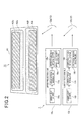
- Fig. 2 is a diagram which schematically shows a mode suitable for description with respect to construction of the vehicle head-up display device 1 and an area where a visual image is displayed by the device.
- the vehicle head-up display device 1 is equipped at a predetermined position below a front windshield 11 in a vehicle 10, and it projects light (image light) for displaying a visual image to a projection face 13 formed on the front windshield 11 through a reflection mirror 12, whereby the virtual image is displayed (projected) in front of an occupant of the vehicle 10.
- the projection face 13 may be configured so that a seal having a half mirror function is attached to the projection face 13 or the projection face 13 is subjected to proper processing or the like so that the vehicle occupant can visually recognize the virtual image more clearly.
- the vehicle head-up display device 1 has an upper projection unit 15u and a lower projection unit 151.
- the upper projection unit 15u contains an upper light source 16u having a light source such as a lamp or the like, an upper optical modulator 17u for modulating light emitted from the upper light source 16u in accordance with an image to be displayed as a visual image and outputting the modulated light, and an upper projection optical system 18u for subjecting the modulated light output from the upper optical modulator 17u to various kinds of adjustment such as focus adjustment, enlargement/reduction, etc. to project light (image light) for displaying the visual light.
- an upper light source 16u having a light source such as a lamp or the like
- an upper optical modulator 17u for modulating light emitted from the upper light source 16u in accordance with an image to be displayed as a visual image and outputting the modulated light
- an upper projection optical system 18u for subjecting the modulated light output from the upper optical modulator 17u to various kinds of adjustment such as focus adjustment, enlargement/reduction, etc. to project light (image light) for displaying the visual light.
- the upper projection unit 15u has an upper focal distance adjusting unit 19u for performing adjustment of the interval distance between the upper projection optical system 18u and the upper reflection mirror 12u and other adjustments of the projection optical system, thereby adjusting the focal distance of the virtual image to be displayed with the light projected from the upper projection unit 15u.
- a front windshield corresponding area A1 is formed in the area corresponding to the front windshield 11.
- An upper virtual image displayable area A2u is formed in an area which is located at an upper portion of the front windshield corresponding area A1 and provided so as to extend over a substantially upper half portion of the front windshield corresponding area A1.
- the upper virtual image displayable area A2u is a largest area where a virtual image can be displayed by the upper projection unit 15u.
- various kinds of mechanisms related to the upper projection unit 15u are adjusted so that a virtual image to be displayed on the basis of an image projected by the upper projection unit 15u is displayed within the upper virtual image displayable area A2u, and the upper projection unit 15u can display a virtual image at any position within the upper virtual image displayable area A2u.
- the displaying of a virtual image within the upper virtual image displayable area A2u means that the virtual image is formed so that the vehicle occupant of the vehicle 10 can visually recognize the virtual image within the area concerned, but it does not mean that an image is projected within the area concerned.
- a virtual image is displayed in a specific area
- an upper virtual image display area A3u is formed in an area corresponding to an upper portion of the upper virtual image displayable area A2u, that is, an area corresponding to an upper area of the front windshield 11.
- the upper virtual image display area A3u is an area in which the upper projection unit 15u actually displays a virtual image. That is, the upper projection unit 15u can display a virtual image at any position of the upper virtual image displayable area A2u, but actually displays a virtual image within the upper virtual image display area A3u by software-based means.
- the lower projection unit 151 has a lower light source 161, a lower optical modulator 17., a lower projection optical system 181 and a lower focal distance adjusting unit 191 as in the case of the upper projection unit 15u.
- a lower virtual image displayable area A2l as a largest area where a virtual image can be displayed by the lower projection unit 151 is formed in an area which is located at a lower portion of the front windshield corresponding area A1 and provided so as to extend over a substantially lower half portion of the front windshield corresponding area A1, and a lower virtual image display area A31 is formed at the lower portion of the lower virtual image displayable area A21.
- the lower virtual image display area A3l is an area where the lower projection unit 151 actually displays a virtual area, and is formed in an area corresponding to the lower area of the front windshield 11.
- Fig. 3 is a block diagram showing the functional construction of the vehicle head-up display device 1.
- a traveling state detector 20 (traveling state detecting means) detects the traveling state of the vehicle 10 and outputs it to a controller 21.
- the traveling state detector 20 is connected to a sensor for detecting the state of a parking brake, detects on the basis of a detection value of the sensor whether the vehicle 10 is set to be stopped while the parking brake is actuated, and outputs a detection result to the controller 21.
- the traveling state detector 20 calculates the speed of the vehicle 10 on the basis of a vehicle speed pulse of the vehicle 10, and outputs it to the controller 21. Any method may be used as a method of determining the speed of the vehicle 10.
- a road condition recognizer 22 recognizes the road condition around the vehicle 10, and outputs a recognition result to the controller 21.
- the road state recognizer 22 is provided at a predetermined positon of the front portion of the vehicle 10, and connected to a camera 23 for imaging a front side of the vehicle 10.
- the road condition recognizer 22 determines whether any other vehicle exists in front of the vehicle 10, and outputs the determination result to the controller 21.
- a content management unit 25 is a function block for managing contents, and has at least the following function.
- the content managing unit 25 is connected to a short-distance radio communication module 26 for performing radio communication in conformity with the standards for short-distance radio communication such as Bluetooth (registered trademark), and configured to be communicable with a cellular phone 27 owned by an occupant of the vehicle 10 or the like through the module.
- a terminal which communicates with the content managing unit 25 is not limited to the cellular phone 27, but may be a notebook PC, a tablet terminal or the like.
- An application having at least the following two functions is preinstalled in the cellular phone 27.
- a first function is the following function: when a reception-detectable mail such as a mail based on SMS, a Web mail or the like is received, the reception concerned is notified to the content managing unit 25 through the short-distance radio communication module 26.
- the content managing unit 25 can arbitrarily inquire about reception or non-reception of a mail to the cellular phone 27 under the control of the controller 21, and acquire reception or non-reception of a mail.
- a second function is the following function: when news such as news conformed with the standards for RSS or the like is distributed, information representing the news is output to the content managing unit 25 as data of a predetermined format.
- the content management unit 25 can arbitrarily inquire about distribution or non-distribution of new news to the cellular phone 27 under the control of the controller 21, and acquire information representing the new news when the new news has been distributed.
- the content managing unit 25 is connected to an in-vehicle audio device 28.
- the content managing unit 25 communicates with the in-vehicle audio device 28 in conformity with a predetermined protocol to acquire information on a content reproduced by the in-vehicle audio device 28 and output the information to the controller 21.
- the information on the content is information on the music being reproduced, for example, the title of the music, an artist' s name, a reproduction time, etc.
- the in-vehicle audio device 28 reproduces a radiobroadcast program
- the information is information on the program being reproduced.
- a navigation managing unit 29 is connected to an in-vehicle navigation device 30 mounted in the vehicle 10, and arbitrarily obtains information on navigation from the device concerned. Then, the navigation managing unit 29 outputs information on proper navigation to the controller 21 at a proper timing while the in-vehicle navigation device 30 performs navigation.
- the navigation managing unit 29 when the navigation managing unit 29 detects that the vehicle 10 approaches to a position at a predetermined distance (for example, 700m) from an intersection at which the vehicle should turn to the right/left, the navigation managing unit 29 outputs information representing this fact to the controller 21. Furthermore, for example when the navigation managing unit 29 detects that the vehicle 10 approaches to a position at a predetermined distance from a destination, the navigation managing unit 29 outputs information representing this fact to the controller 21. Furthermore, the timing (trigger) at which the navigation managing unit 29 outputs the information on the navigation and also the information to be output are determined in advance.
- a predetermined distance for example, 700m
- the controller 21 has CPU, control programs executed by CPU, ROM for storing data associated with the control programs, RAM functioning as a working area, and other peripheral circuits and peripheral equipment, and concentrically controls the respective parts of the vehicle head-up display device 1.
- the controller 21 has an upper display controller 35u, and a lower display controller 351.
- the functions of the respective function blocks equipped to the controller 21 are executed by the cooperation between hardware and software, for example by CPU's reading of the programs or the like. The functions of the respective function blocks will be described later.
- the upper projection unit 15u displays a virtual image in the upper virtual image display area A3u
- the lower projection unit 151 displays a virtual image in the lower virtual image display area A3l.
- the focal distance of a virtual image displayed in the upper virtual image display area A3u is set to be longer than the focal distance of a virtual image displayed in the lower virtual image display area A31.
- the upper virtual image display area A3u is an area formed at the upper portion of the front windshield 11, and a target which the occupant of the vehicle 10 visually recognizes through the upper portion of the front windshield 11 is normally a building, a mountain, the sky or the like which is far away from the eyes of the vehicle occupant. Therefore, the probability that the focal point of the vehicle occupant's eyes when the occupant visually recognizes the outside of the vehicle through the upper portion of the front windshield 11 is matched with the focal point when the occupant visually recognizes a target located in the distance is high.
- the focal distance of the virtual image displayed in the upper virtual image display area A3u is set to be longer than the focal distance of the virtual image displayed in the lower virtual image display area A3l.
- the focal distance of the virtual image displayed in the upper virtual image display area A3u is set to the focal distance corresponding to a building, a mountain or the like located in the distance or the focal distance of the sky, for example. Accordingly, when the occupant of the vehicle 10 visually recognizes the virtual image displayed in the upper virtual image display area A3u, the load for focusing the eyes is reduced, and thus the comfort is enhanced.
- the lower virtual image display area A3l is an area formed at the lower portion of the front windshield 11.
- a target which the occupant of the vehicle 10 visually recognizes through the lower portion of the front windshield 11 is the hood (bonnet) of the vehicle 10 in the neighborhood of the occupant's eyes or a rear portion of another vehicle traveling at the front side of the vehicle 10. Therefore, the probability that the focal point of the occupant when the occupant visually recognizes the outside of the vehicle through the lower portion of the front windshield 11 is matched with the focal point when the occupant visually recognizes a target located in the neighborhood of the occupant is high.
- the focal distance of the virtual image displayed in the lower virtual image display area A3l is set to be shorter than the focal distance of the virtual image displayed in the upper virtual image display area A3u.
- the focal distance of the virtual image displayed in the lower virtual image display area A3l is set to the focal distance corresponding to the hood (bonnet). Accordingly, a load of focusing the eyes when the occupant of the vehicle 10 visually recognizes the virtual image displayed in the lower virtual image display area A31 is reduced, and the comfort is enhanced.
- the focal distance of a virtual image displayed at the upper side is set to be longer than the focal distance of a virtual image displayed at the lower side, thereby reducing the load when the occupant focuses his/her eyes on the virtual images.
- Fig. 4(A) is a diagram showing an example of a virtual image displayed under traveling.
- a virtual image G1 associated with information representing that the vehicle should turn to the right at an intersection located ahead of the vehicle by 700m is displayed in the lower virtual image display area A3l.
- Fig. 4(A) it is set as one of triggers for displaying the virtual image associated with the information on the navigation that the interval distance between the intersection at which the vehicle should turn to the right/left and the vehicle 10 is equal to 700m.
- the lower display controller 351 monitors, on the basis of an input from the navigation managing unit 29, whether the interval distance between an intersection at which the vehicle should turn to the right/left and the vehicle 10 is equal to 700m.
- the interval distance is equal to 700m (in this example, it is assumed that the vehicle turns to the right at an intersection which is located ahead of the vehicle by 700m)
- the lower virtual image display area A31 generates image date associated with the information representing this fact, that is, image data associated with the virtual image G1.
- the lower display controller 351 modulates light emitted from the lower light source 161 on the basis of the generated image data through the lower optical modulator 171 of the lower projection unit 151, and then projects the image (light for the virtual image G1) from the lower projection optical system 181, whereby the virtual image G1 is displayed in the lower virtual image display area A3l.
- the virtual image G21 is displayed at a proper timing and at a proper position as shown in Fig. 4(A) .
- Fig. 4(B) is a diagram showing another example of the virtual image displayed during traveling.
- a virtual image G2 associated with information representing that attention should be paid to another forehand vehicle and a virtual image G3 associated with information representing the speed of the vehicle 10 are displayed in the lower virtual image display area A31.
- the lower display controller 351 monitors on the basis of inputs from the traveling state detector 20 and the road condition recognizer 22 whether another vehicle exists in front and the vehicle 10 is set to travel at a speed which is equal to or higher than the predetermined speed.
- the lower display controller 351 generates image data associated with the virtual image G2, and controls the lower projection unit 151 on the basis of the image data, whereby the virtual image G2 is displayed in the lower virtual image display area A31.
- the virtual image G3 associated with the information representing the speed of the vehicle 10 is displayed at a predetermined position within the lower virtual image display area A3l. Furthermore, during traveling, the lower display controller 351 detects the speed of the vehicle 10 on the basis of an input from the traveling state detector 20 at a predetermined sampling period, generates image data associated with the virtual image G3 based on the detected speed of the vehicle 10, and controls the lower projection unit 151 on the basis of the generated image data to display the virtual image G3 in the lower virtual image display area A31.
- the information displayed in the lower virtual image display area A31 is not limited to that exemplified in Fig. 4 (B) .
- the device may be configured so that a pedestrian is detectable on the basis of an output of a camera 23, another imaging device or a sensor, and when a pedestrian is detected, this fact may be displayed to invite attention.
- the device may be configured so that it is detectable on the basis of an output of a camera 23, another imaging device or a sensor whether the vehicle 10 deviates from the traffic lane, and when it is detected that the vehicle deviates from the traffic lane, this fact may be displayed to give warning. All the existing techniques may be used for the detection of a pedestrian and detection of deviation from traffic lanes.
- a virtual image associated with information on the driving is broadly displayable in the lower virtual image display area A31.
- Fig. 5 is a flowchart showing the operation of the vehicle head-up display device 1 when the vehicle 10 under traveling stops. It is assumed that the vehicle 10 is traveling at the start time point of the flowchart of Fig. 5 .
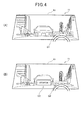
- Fig. 6 is a diagram showing an example of a virtual image displayed when the vehicle stops.
- the controller 21 monitors on the basis of an input from the traveling state detector 20 whether the vehicle 10 stops while applying a parking brake (step SA1).
- step SA1 the controller 21 allows display of a virtual image to the upper virtual image display area A3u which is prohibited from displaying a virtual image under traveling, whereby the upper virtual image display area A3u is shifted to a virtual image displayable state (step SA2).
- the upper display controller 35u of the controller 21 acquires information to be displayed as a virtual image in the upper virtual image display area A3u (step SA3).
- a virtual image G4 associated with information representing this fact is displayed in the upper virtual image display area A3u in response to the stop of the vehicle 10.
- a virtual image G5 associated with information representing the news is displayed in the upper virtual image display area A3u in response to the stop of the vehicle 10.
- a virtual image G6 associated with information on the content is displayed in the upper virtual image display area A3u in response to the stop of the vehicle 10.
- the respective virtual images G4, G5 and G6 are virtual images which are simultaneously displayed with common light, and thus they should be originally captured as one virtual image. However, for convenience of explanation, these virtual images are represented by difference reference numerals, and described while discriminated from one another.
- step SA3 the upper display controller 35u controls the content managing unit 25 to inquire about reception or non-reception of a mail (s) to the cellular phone 27.
- the upper display controller 35u acquires information representing reception of the mail as information to be displayed as a virtual image (virtual image G4).
- step SA3 the upper display controller 35u controls the content managing unit 25 to inquire about distribution or non-distribution of new news to the cellular phone 27.
- the upper display controller 35u acquires information representing the new news as information to be displayed as a virtual image (virtual image G5).
- step SA3 the upper display controller 35u controls the content managing unit to inquire whether any content is reproduced by the in-vehicle audio device 28. When some content is reproduced, the upper display controller 35u acquires information on the content as information to be displayed as a virtual image (virtual image G6).
- the upper display controller 35u generates image data containing various information acquired in step SA3 (step SA4).
- the position at which the information is displayed as a virtual image in the upper virtual image display area A3u is predetermined, and proper image data is generated in conformity with the position at which each information should be displayed in step SA4.
- the upper display controller 35u modulates light emitted from the upper light source 16u on the basis of the image data generated in step SA4 through the upper optical modulator 17u of the upper projection unit 15u, and then projects an image (light) from the upper projection optical system 18u, thereby displaying the virtual images G4, G5 and G6 in the lower virtual image display area A31 (step SA5).
- the upper display controller 35u stops the display of the virtual image in the upper virtual display area A3u, and then prohibits the display of the virtual image in the area concerned. Accordingly, the virtual image is displayed in the upper virtual display area A3u only during stopping.
- virtual images associated with information on the speed of the vehicle 10 and information relating to the driving such as information on navigation, information on the traveling condition of the vehicle 10, etc. are displayed in the lower virtual image display area A3l.
- virtual images associated with information on mails, entertainment-based information (information containing information other than the information on the driving) such as information on news, information on reproduction of the in-vehicle audio device 28, etc. are displayed in the upper virtual image display area A3u. The reason for this is as follows.
- the vehicle head-up display device 1 displays the virtual image associated with each information described above in the upper virtual image display area A3u.
- the vehicle head-up display device 1 executes display of a virtual image in the upper virtual image display area A3u during only stopping.
- the vehicle head-up display device 1 displays plural virtual images different in focal distance.
- the focal distance of the virtual image displayed at the upper side is set to be longer than the focal distance of the virtual image displayed at the lower side in the front windshield corresponding area A1, thereby enhancing the comfort of the vehicle occupant. That is, proper display can be performed in consideration of the characteristic that the vehicle head-up display device 1 is mounted in a vehicle.
- the vehicle head-up display device 1 projects light to the projection face 13 formed on the front windshield 11, and displays a virtual image in the front windshield corresponding area A1 as the area corresponding to the front windshield 11.
- plural virtual display areas which are different in focal distance of a virtual image to be displayed that is, the upper virtual image display area A3u and the lower virtual image display area A31 are formed in the front windshield corresponding area A1.
- the projection face 13 is formed on the front windshield 11.
- the projection face is not necessarily formed on the front windshield 11, and it may be formed on a member which is provided so as to correspond to the front windshield 11.
- a dedicated half mirror may be provided as the projection face 13 at a proper position in the neighborhood of the front windshield 11, so that virtual images are formed in the upper virtual display area A3u and the lower virtual image display area A31 by projecting light to the half mirror.
- the focal distance of the virtual image displayed in the virtual image display area (the upper virtual image display area A3u) located at the upper side is set to be longer than the focal distance of the virtual image displayed in the virtual image display area (the lower virtual image display area A31) located at the lower side.
- the focal distance of the virtual image displayed at the upper side is set to be longer than the focal distance of the virtual image displayed at the lower side, whereby the load imposed on the vehicle occupant when the vehicle occupant focuses his/her eyes.
- At least the upper virtual image display area A3u formed in the area corresponding to the upper area of the front windshield 11 and the lower virtual image display area A31 formed in the area corresponding to the lower area of the front windshield 11 are formed in the front windshield corresponding area A1.
- a virtual image having a proper focal distance corresponding to a position in the front windshield corresponding area A1 can be displayed in each of the upper virtual image display area A3u and the lower virtual image display area A3l.
- a virtual image associated with information relating to the driving is displayed in the lower virtual image display area A3l, and a virtual image associated with information containing information other than the information relating to the driving is displayed in the upper virtual image display area A3u.
- the virtual image displayed in the upper virtual image display area A3u can be visually recognized with relax by the vehicle occupant.
- the traveling state detector 20 (the traveling state detecting means) for detecting the traveling state is provided, and the vehicle head-up display device 1 displays a virtual image in the upper virtual image display area A3u when the traveling state detector 20 detects that the vehicle 10 is under stopping.
- the projection unit for projecting light (image light) for displaying a virtual image is provided for each of the plural virtual image display areas formed in the front windshield corresponding area A1.
- the focal distance of the virtual image to be displayed can be surely different among the plural virtual image display areas with a simple construction.
- the projecting portion is provided every virtual image display area to display virtual images whose focal distances are different among the virtual image display areas.
- the construction for displaying virtual images whose focal distances are different among the virtual image display areas is not limited to the above construction.
- it may be implemented by operating a projection optical system based on one projecting unit and a reflection lens or by using software-based means.
- a virtual image associated with information representing the suffix of a building or the like which can be visually recognized through the upper portion of the front windshield 11 may be displayed by using the technique of AR (Augmented Reality) as shown in Fig. 7(A) .
- AR Augmented Reality
- a contributed short sentence may be displayed.
- various kinds of distributed information such as information associated with various kinds of SNS (Social Networking Service), information on sites of the Internet, road traffic information, etc., still pictures such as photographs, etc. , moving pictures such as movies, promotion video, etc., may be displayed in the upper virtual image display area A3u.
- SNS Social Networking Service
- the vehicle head-up display device 1 displays the virtual image G4 associated with information on a mail in the upper virtual image display area A3u, and also on the basis of news distributed to the cellular phone 27, the vehicle head-up display device 1 displays the virtual image G5 associated with information representing the news in the upper virtual image display area A3u.
- the vehicle head-up display device 1 or the in-vehicle navigation device 30 connected to this device may be configured to directly acquire mails, news or other entertainment-based information by accessing to an external server and receiving distribution from the external server.
- the vehicle head-up display device 1 or the equipment connected to the device 1 may be provided with a communication module for communicating with the external server through a network such as the Internet or the like, or communicates with the external server through the cellular phone 27.
- the focal distance of the virtual image may be made different between the right and left sides in the front windshield corresponding area A1.
- an area A4 in which a camera picture for compensating for a driver' s blind spot is displayed is formed at the lower left side when the front windshield corresponding area A1 is viewed from the vehicle occupant.
- a dedicated camera device for imaging a picture for compensating the driver's blind spot is mounted in the vehicle 10, and a proper input from the camera device to the vehicle head-up display device 1 can be performed.
- the focal distance of a virtual image displayed in the area A4 is set to be shorter than the focal distance of a virtual image displayed at the right side of the area A4.
- the focal distance of a virtual image displayed in the area A4 in Fig. 7(B) is set to be shorter than the focal distance of a virtual image G7 displayed in Fig. 7(C) .
- the picture for compensating for the driver's blind spot is a picture which is assumed to be visually recognized when the vehicle 10 is started to move, backed, stopped or the like.
- the driver visually recognizes meters provided to the vehicle 10, the state of a gear or the like or visually recognizes the neighborhood of the vehicle 10 in many cases.
- the load imposed on the driver who focuses his/her eyes can be reduced by shortening the focal distance of the virtual image displayed in the area A4.
- a projecting unit for displaying the virtual image in the area A4 may be provided.
- proper display based on the fact that the vehicle head-up display device 1b is provided in the vehicle 10 can be performed by making the focal distance of the virtual image different between the right and left sides.
- a virtual image on the driving may be displayed in the upper virtual image display area A3u during traveling.
- a virtual-image displayable area is set with respect to a predetermined area in the upper virtual image display area A3.
- a virtual image associated with information on the driving for example, information representing the presence or absence of a pedestrian, information representing a road condition (for example, the shape of a road, the presence or absence of a preceding vehicle, road congestion or the like) or information on navigation is displayed in the area concerned.
- means for acquiring the information associated with the virtual image to be displayed may be used any means, for example, means for acquiring the information on the basis of an output of the camera 23, means for acquiring the information through a network or the like.
- the virtual image can be displayed in a proper style even under a condition that the field of vision through the front windshield 11 is bad with the construction as described above.
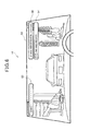
- Fig. 8 is a schematic diagram which shows, in a suitable style for description, the construction of the vehicle head-up display device 1b according to the second embodiment and an area in which a virtual image is displayed by the device.
- constituent elements of the vehicle head-up display device 1b according to the second embodiment the same constituent elements as the vehicle head-up display device 1 according to the first embodiment are represented by the same reference numerals, and the description thereof is omitted.
- the vehicle head-up display device 1b has a projection unit 15m for projecting light for a virtual image
- the projection unit 15m has a light source 16m, an optical modulator 17m and a projection optical system 18m.
- An image (light) emitted from the projection optical system 18m is projected to the projection face 13 formed on the front windshield 11 through a reflection mirror 12m to form a virtual image (image).
- a virtual image displayable area A5 is formed in the front windshield corresponding area A1.
- the virtual image displayable area A5 is the maximum area where a virtual image can be displayed by the projection unit 15m. That is, the projection unit 15m can display a virtual image (image) at any position within the virtual image displayable area A5.
- the lower virtual image display area A3l described in the first embodiment is formed in the area corresponding to the lower area of the front windshield 11.
- Fig. 9 is a block diagram showing the functional construction of the vehicle head-up display device 1b.
- the controller 21 of the vehicle head-up display device 1b has a display controller 35m in place of the upper display controller 35u and the lower display controller 351.
- the vehicle head-up display device 1b performs the following operation.
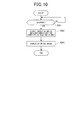
- Fig. 10 is a flowchart showing the operation of the vehicle head-up display device 1b when the vehicle 10 under traveling stops. It is assumed that the vehicle 10 is traveling at the start time point of the flowchart of Fig. 10 .
- the display controller 35m of the controller 21 monitors on the basis of an input from the traveling state detector 20 whether the vehicle 10 is stopped under the state that the parking brake is activated (step SB1).
- the controller 21 releases prohibition of display of virtual images in the areas other than the lower virtual image display area A31, and allows display of virtual images in the whole area of the virtual image displayable area A5 (step SB2). That is, the whole area of the virtual image displayable area A5 is set as the virtual-image displayable area.
- the display controller 35m controls the projection unit 15m to display a proper image (step SB3).
- the display controller 35m can also display a virtual image in an area other than the lower virtual image display area A3l.
- a virtual image associated with a television picture is set to be displayed in an area A6 from the center of the virtual image displayable area A5 to the upper portion thereof (see Fig. 11 ) while the vehicle 10 stops with the parking brake being activated).
- the vehicle 10 is provided with a television device, and the vehicle head-up display device 1b is assumed to receive a proper input from the television device.
- the display controller 35m displays a virtual image associated with a television picture in the area from the center of the virtual image displayable area A5 to the upper portion thereof as shown in Fig. 11 .
- a virtual image is allowed to be displayed in an area which corresponds to the virtual image displayable area A5 and is remarkably broader and easier to be visually recognized by the vehicle occupant as compared with the lower virtual image display area A31. Therefore, as compared with a case where virtual images are displayed in only the lower virtual image display area A3l, a larger variety of information can be supplied to the vehicle occupant. Furthermore, for example, when a virtual image associated with a movie or promotion video picture is displayed, pictures having presence can be supplied.
- the area which enables display of a virtual image during stopping is not limited to the virtual image displayable area A5.
- the area corresponding to the upper virtual image display area A3u of the first embodiment described above may be set as the area which enables display of a virtual image during stopping. That is, the virtual image is allowed to be displayed in the area other than the lower virtual image display area A3l, whereby the effect described above can be achieved.
- the information associated with the virtual image displayed during stopping is not limited to the above examples. That is, any information such as mails, information relating to news distribution, contents which are described as examples in the first embodiment may be used.
- the invention described with reference to the second embodiment is applicable to vehicle head-up display devices whose types are different from the type of vehicle head-up display device for forming a virtual image by projecting light to the projection face.
- the present invention is applicable to a vehicle head-up display device in which the front windshield 11 is constructed by a translucent type liquid panel or other types of panels and an image is directly displayed on the shield. That is, the present invention is broadly applicable to a vehicle head-up display device for displaying an "image" such as a virtual image, a picture or the like.
- the vehicle head-up display device 1b changes the mode of the area for displaying the virtual image (image) in accordance with the traveling state detected by the traveling state detector 20.
- the virtual image can be displayed in only the proper area corresponding to the traveling state of the vehicle 10. That is, the vehicle head-up display device 1b can perform proper display based on the fact that the vehicle head-up display device 1b is mounted in the vehicle 10.
- the vehicle head-up display device 1b changes the mode of the area for displaying the virtual image (image) in the front windshield corresponding area A1 according to the traveling state detected by the traveling state detector 20.
- the traveling state detector 20 when it is detected by the traveling state detector 20 that the vehicle 10 is under traveling, the area corresponding to the lower area of the front windshield 11 is set as a virtual-image (image) display area, and when it is detected by the traveling state detector 20 that the vehicle 10 is under stopping, the area containing the area other than the lower portion of the front windshield 11 is set as the virtual-image (image) display area.
- a virtual image can be displayed in an area which is remarkably broader and easier to be visually recognized by the vehicle occupant as compared with the lower virtual image display area A3l, which corresponds to the virtual image displayable area A5. Therefore, as compared with the case where a virtual image is displayed in only the lower virtual image display area A3l, a larger variety of information can be supplied to the vehicle occupant. Furthermore, for example when a virtual image associated with a movie or a promotion video picture is displayed, pictures giving presence can be supplied.
- the vehicle head-up display device may be configured by combining at least a part of the technique described with reference to the first embodiment and at least a part of the technique described with reference to the second embodiment.
- the display modes of the upper virtual image display area A3u and the lower virtual image display area A3l may be changed in accordance with the traveling state of the vehicle 10.
Abstract
Description
- The present invention relates to a head-up display apparatus for a vehicle which is mounted in a vehicle.
- A head-up display apparatus which is mounted in a vehicle has been conventionally known (see
Patent Document 1, for example). - Patent Document 1:
JP-A-H8-192664 - With respect to apparatuses mounted in vehicles such as the above-described head-up display apparatus, there is a need that proper display is performed based on the characteristic that that they are mounted in vehicles.
- The present invention has been implemented in view of the foregoing situation, and has an object to perform proper display based on the characteristic that an apparatus is mounted in a vehicle.
- In order to attain the above object, a head-up display apparatus for a vehicle that displays a virtual image is characterized in that a plurality of virtual images having different focal distances are displayed, for example.
- According to the present invention, the head-up display apparatus can perform proper display based on the characteristic that the apparatus is mounted in a vehicle.
-
- [
Fig. 1 ] is a diagram showing a display mode of a virtual image based on a head-up display apparatus for a vehicle according to a first embodiment. - [
Fig. 2 ] is a diagram showing an area where a virtual image is displayed. - [
Fig. 3 ] is a diagram showing a functional construction of the head-up display apparatus for the vehicle. - [
Fig. 4 ] is a diagram showing a display example of a virtual image when the vehicle travels. - [
Fig. 5 ] is a flowchart showing the operation of the head-up display apparatus for the vehicle. - [
Fig. 6 ] is a diagram showing a display example of a virtual image when the vehicle stops. - [
Fig. 7 ] is a diagram showing a display example of a virtual image. - [
Fig. 8 ] is a diagram showing an area where a virtual image is displayed in a head-up display apparatus for a vehicle according to a second embodiment. - [
Fig. 9 ] is a diagram showing a functional construction of the head-up display apparatus for the vehicle. - [
Fig. 10 ] is a flowchart showing the operation of the head-up display apparatus for the vehicle. - [
Fig. 11 ] is a diagram showing a display example of a virtual image when the vehicle stops. - Embodiments according to the present invention will be described hereunder with reference to the drawings.
-
Fig. 1 is a diagram which schematically shows amode suitable for description with respect to a display mode of a visual image based on a head-updisplay device 1 for a vehicle according to an embodiment.Fig. 2 is a diagram which schematically shows a mode suitable for description with respect to construction of the vehicle head-updisplay device 1 and an area where a visual image is displayed by the device. - As shown in
Fig. 1 , the vehicle head-updisplay device 1 is equipped at a predetermined position below afront windshield 11 in avehicle 10, and it projects light (image light) for displaying a visual image to aprojection face 13 formed on thefront windshield 11 through areflection mirror 12, whereby the virtual image is displayed (projected) in front of an occupant of thevehicle 10. Theprojection face 13 may be configured so that a seal having a half mirror function is attached to theprojection face 13 or theprojection face 13 is subjected to proper processing or the like so that the vehicle occupant can visually recognize the virtual image more clearly. - As shown in
Figs. 1 ,2 , the vehicle head-updisplay device 1 has anupper projection unit 15u and alower projection unit 151. - The
upper projection unit 15u contains anupper light source 16u having a light source such as a lamp or the like, an upperoptical modulator 17u for modulating light emitted from theupper light source 16u in accordance with an image to be displayed as a visual image and outputting the modulated light, and an upper projectionoptical system 18u for subjecting the modulated light output from the upperoptical modulator 17u to various kinds of adjustment such as focus adjustment, enlargement/reduction, etc. to project light (image light) for displaying the visual light. Furthermore, theupper projection unit 15u has an upper focaldistance adjusting unit 19u for performing adjustment of the interval distance between the upper projectionoptical system 18u and theupper reflection mirror 12u and other adjustments of the projection optical system, thereby adjusting the focal distance of the virtual image to be displayed with the light projected from theupper projection unit 15u. - Here, as shown in
Fig. 2 , a front windshield corresponding area A1 is formed in the area corresponding to thefront windshield 11. An upper virtual image displayable area A2u is formed in an area which is located at an upper portion of the front windshield corresponding area A1 and provided so as to extend over a substantially upper half portion of the front windshield corresponding area A1. The upper virtual image displayable area A2u is a largest area where a virtual image can be displayed by theupper projection unit 15u. That is, various kinds of mechanisms related to theupper projection unit 15u are adjusted so that a virtual image to be displayed on the basis of an image projected by theupper projection unit 15u is displayed within the upper virtual image displayable area A2u, and theupper projection unit 15u can display a virtual image at any position within the upper virtual image displayable area A2u. - Here, the displaying of a virtual image within the upper virtual image displayable area A2u means that the virtual image is formed so that the vehicle occupant of the
vehicle 10 can visually recognize the virtual image within the area concerned, but it does not mean that an image is projected within the area concerned. In the following description, when "a virtual image is displayed in a specific area" is expressed, it means that the virtual image is formed so that the vehicle occupant of thevehicle 10 can visually recognize the virtual image within the specific area. - As shown in
Fig. 2 , an upper virtual image display area A3u is formed in an area corresponding to an upper portion of the upper virtual image displayable area A2u, that is, an area corresponding to an upper area of thefront windshield 11. The upper virtual image display area A3u is an area in which theupper projection unit 15u actually displays a virtual image. That is, theupper projection unit 15u can display a virtual image at any position of the upper virtual image displayable area A2u, but actually displays a virtual image within the upper virtual image display area A3u by software-based means. - As shown in
Fig. 2 , thelower projection unit 151 has alower light source 161, a lower optical modulator 17., a lower projectionoptical system 181 and a lower focaldistance adjusting unit 191 as in the case of theupper projection unit 15u. A lower virtual image displayable area A2l as a largest area where a virtual image can be displayed by thelower projection unit 151 is formed in an area which is located at a lower portion of the front windshield corresponding area A1 and provided so as to extend over a substantially lower half portion of the front windshield corresponding area A1, and a lower virtual image display area A31 is formed at the lower portion of the lower virtual image displayable area A21. The lower virtual image display area A3l is an area where thelower projection unit 151 actually displays a virtual area, and is formed in an area corresponding to the lower area of thefront windshield 11. -
Fig. 3 is a block diagram showing the functional construction of the vehicle head-updisplay device 1. A traveling state detector 20 (traveling state detecting means) detects the traveling state of thevehicle 10 and outputs it to acontroller 21. Particularly, in this embodiment, thetraveling state detector 20 is connected to a sensor for detecting the state of a parking brake, detects on the basis of a detection value of the sensor whether thevehicle 10 is set to be stopped while the parking brake is actuated, and outputs a detection result to thecontroller 21. Furthermore, thetraveling state detector 20 calculates the speed of thevehicle 10 on the basis of a vehicle speed pulse of thevehicle 10, and outputs it to thecontroller 21. Any method may be used as a method of determining the speed of thevehicle 10. A road condition recognizer 22 recognizes the road condition around thevehicle 10, and outputs a recognition result to thecontroller 21. Particularly, in this embodiment, theroad state recognizer 22 is provided at a predetermined positon of the front portion of thevehicle 10, and connected to acamera 23 for imaging a front side of thevehicle 10. On the basis of an imaging result of thecamera 23, the road condition recognizer 22 determines whether any other vehicle exists in front of thevehicle 10, and outputs the determination result to thecontroller 21. - A
content management unit 25 is a function block for managing contents, and has at least the following function. - That is, the
content managing unit 25 is connected to a short-distanceradio communication module 26 for performing radio communication in conformity with the standards for short-distance radio communication such as Bluetooth (registered trademark), and configured to be communicable with acellular phone 27 owned by an occupant of thevehicle 10 or the like through the module. A terminal which communicates with thecontent managing unit 25 is not limited to thecellular phone 27, but may be a notebook PC, a tablet terminal or the like. - An application having at least the following two functions is preinstalled in the
cellular phone 27. - A first function is the following function: when a reception-detectable mail such as a mail based on SMS, a Web mail or the like is received, the reception concerned is notified to the
content managing unit 25 through the short-distanceradio communication module 26. Thecontent managing unit 25 can arbitrarily inquire about reception or non-reception of a mail to thecellular phone 27 under the control of thecontroller 21, and acquire reception or non-reception of a mail. - A second function is the following function: when news such as news conformed with the standards for RSS or the like is distributed, information representing the news is output to the
content managing unit 25 as data of a predetermined format. Thecontent management unit 25 can arbitrarily inquire about distribution or non-distribution of new news to thecellular phone 27 under the control of thecontroller 21, and acquire information representing the new news when the new news has been distributed. - Furthermore, the
content managing unit 25 is connected to an in-vehicle audio device 28. Thecontent managing unit 25 communicates with the in-vehicle audio device 28 in conformity with a predetermined protocol to acquire information on a content reproduced by the in-vehicle audio device 28 and output the information to thecontroller 21. When the in-vehicle audio device 28 reproduces music recorded in CD, a hard disc or the like, the information on the content is information on the music being reproduced, for example, the title of the music, an artist' s name, a reproduction time, etc. When the in-vehicle audio device 28 reproduces a radiobroadcast program, the information is information on the program being reproduced. - A
navigation managing unit 29 is connected to an in-vehicle navigation device 30 mounted in thevehicle 10, and arbitrarily obtains information on navigation from the device concerned. Then, thenavigation managing unit 29 outputs information on proper navigation to thecontroller 21 at a proper timing while the in-vehicle navigation device 30 performs navigation. - For example, when the
navigation managing unit 29 detects that thevehicle 10 approaches to a position at a predetermined distance (for example, 700m) from an intersection at which the vehicle should turn to the right/left, thenavigation managing unit 29 outputs information representing this fact to thecontroller 21. Furthermore, for example when thenavigation managing unit 29 detects that thevehicle 10 approaches to a position at a predetermined distance from a destination, thenavigation managing unit 29 outputs information representing this fact to thecontroller 21. Furthermore, the timing (trigger) at which thenavigation managing unit 29 outputs the information on the navigation and also the information to be output are determined in advance. - The
controller 21 has CPU, control programs executed by CPU, ROM for storing data associated with the control programs, RAM functioning as a working area, and other peripheral circuits and peripheral equipment, and concentrically controls the respective parts of the vehicle head-updisplay device 1. - As shown in
Fig. 3 , thecontroller 21 has anupper display controller 35u, and alower display controller 351. The functions of the respective function blocks equipped to thecontroller 21 are executed by the cooperation between hardware and software, for example by CPU's reading of the programs or the like. The functions of the respective function blocks will be described later. - Next, a mode of a virtual image displayed by the vehicle head-up
display device 1 will be described in detail. - As described above, the
upper projection unit 15u displays a virtual image in the upper virtual image display area A3u, and thelower projection unit 151 displays a virtual image in the lower virtual image display area A3l. - According to this embodiment, when a virtual image is displayed, the focal distance of a virtual image displayed in the upper virtual image display area A3u is set to be longer than the focal distance of a virtual image displayed in the lower virtual image display area A31. The reason for this is as follows.
- That is, the upper virtual image display area A3u is an area formed at the upper portion of the
front windshield 11, and a target which the occupant of thevehicle 10 visually recognizes through the upper portion of thefront windshield 11 is normally a building, a mountain, the sky or the like which is far away from the eyes of the vehicle occupant. Therefore, the probability that the focal point of the vehicle occupant's eyes when the occupant visually recognizes the outside of the vehicle through the upper portion of thefront windshield 11 is matched with the focal point when the occupant visually recognizes a target located in the distance is high. According to this embodiment, in consideration of this, by adjusting the focal distance of the virtual image with the upper focaldistance adjusting unit 19u, the focal distance of the virtual image displayed in the upper virtual image display area A3u is set to be longer than the focal distance of the virtual image displayed in the lower virtual image display area A3l. For example, the focal distance of the virtual image displayed in the upper virtual image display area A3u is set to the focal distance corresponding to a building, a mountain or the like located in the distance or the focal distance of the sky, for example. Accordingly, when the occupant of thevehicle 10 visually recognizes the virtual image displayed in the upper virtual image display area A3u, the load for focusing the eyes is reduced, and thus the comfort is enhanced. - The lower virtual image display area A3l is an area formed at the lower portion of the
front windshield 11. A target which the occupant of thevehicle 10 visually recognizes through the lower portion of thefront windshield 11 is the hood (bonnet) of thevehicle 10 in the neighborhood of the occupant's eyes or a rear portion of another vehicle traveling at the front side of thevehicle 10. Therefore, the probability that the focal point of the occupant when the occupant visually recognizes the outside of the vehicle through the lower portion of thefront windshield 11 is matched with the focal point when the occupant visually recognizes a target located in the neighborhood of the occupant is high. According to this embodiment, in consideration of this, by adjusting the focal distance of the virtual image with the lower focaldistance adjusting unit 191, the focal distance of the virtual image displayed in the lower virtual image display area A3l is set to be shorter than the focal distance of the virtual image displayed in the upper virtual image display area A3u. For example, the focal distance of the virtual image displayed in the lower virtual image display area A3l is set to the focal distance corresponding to the hood (bonnet). Accordingly, a load of focusing the eyes when the occupant of thevehicle 10 visually recognizes the virtual image displayed in the lower virtual image display area A31 is reduced, and the comfort is enhanced. - That is, according to this embodiment, in consideration of the characteristic that the probability that with respect to targets visually-recognized through the
front windshield 11, a target located at an upper side exists at a nearer position than a target located at a lower side is high, the focal distance of a virtual image displayed at the upper side is set to be longer than the focal distance of a virtual image displayed at the lower side, thereby reducing the load when the occupant focuses his/her eyes on the virtual images. - Next, a display mode of a virtual image "under traveling" of the
vehicle 10 will be described by citing a specific example. - In this example, during traveling of the
vehicle 10, only the lower virtual image display area A3l is set to a virtual image displayable area. In other words, display of a virtual image in the upper virtual image display area A3u is prohibited. Accordingly, display of a virtual image at a proper position in consideration of the traveling of the vehicle is performed. -
Fig. 4(A) is a diagram showing an example of a virtual image displayed under traveling. - In the example of
Fig. 4(A) , a virtual image G1 associated with information representing that the vehicle should turn to the right at an intersection located ahead of the vehicle by 700m is displayed in the lower virtual image display area A3l. - The operation of the vehicle head-up
display device 1 when the virtual image G1 associated with the example ofFig. 4(A) is displayed will be described hereunder. - In the example of
Fig. 4(A) , it is set as one of triggers for displaying the virtual image associated with the information on the navigation that the interval distance between the intersection at which the vehicle should turn to the right/left and thevehicle 10 is equal to 700m. During traveling, thelower display controller 351 monitors, on the basis of an input from thenavigation managing unit 29, whether the interval distance between an intersection at which the vehicle should turn to the right/left and thevehicle 10 is equal to 700m. When the interval distance is equal to 700m (in this example, it is assumed that the vehicle turns to the right at an intersection which is located ahead of the vehicle by 700m), the lower virtual image display area A31 generates image date associated with the information representing this fact, that is, image data associated with the virtual image G1. Subsequently, thelower display controller 351 modulates light emitted from the lowerlight source 161 on the basis of the generated image data through the loweroptical modulator 171 of thelower projection unit 151, and then projects the image (light for the virtual image G1) from the lower projectionoptical system 181, whereby the virtual image G1 is displayed in the lower virtual image display area A3l. As described above, the virtual image G21 is displayed at a proper timing and at a proper position as shown inFig. 4(A) . -
Fig. 4(B) is a diagram showing another example of the virtual image displayed during traveling. - In the example of
Fig. 4(B) , a virtual image G2 associated with information representing that attention should be paid to another forehand vehicle and a virtual image G3 associated with information representing the speed of thevehicle 10 are displayed in the lower virtual image display area A31. - The operation of the vehicle head-up
display device 1 when the virtual images G2, G3 associated with the example ofFig. 4(B) will be described hereunder. - In the example of
Fig. 4(B) , when another vehicle exists in front of thevehicle 10, it is set as one of triggers for displaying the virtual image G2 that thevehicle 10 travels at a speed which is equal to or higher than a predetermined speed. During traveling, thelower display controller 351 monitors on the basis of inputs from the travelingstate detector 20 and theroad condition recognizer 22 whether another vehicle exists in front and thevehicle 10 is set to travel at a speed which is equal to or higher than the predetermined speed. When thevehicle 10 falls into the above state, thelower display controller 351 generates image data associated with the virtual image G2, and controls thelower projection unit 151 on the basis of the image data, whereby the virtual image G2 is displayed in the lower virtual image display area A31. - Furthermore, in the example of
Fig. 4(B) , during traveling, the virtual image G3 associated with the information representing the speed of thevehicle 10 is displayed at a predetermined position within the lower virtual image display area A3l. Furthermore, during traveling, thelower display controller 351 detects the speed of thevehicle 10 on the basis of an input from the travelingstate detector 20 at a predetermined sampling period, generates image data associated with the virtual image G3 based on the detected speed of thevehicle 10, and controls thelower projection unit 151 on the basis of the generated image data to display the virtual image G3 in the lower virtual image display area A31. - The information displayed in the lower virtual image display area A31 is not limited to that exemplified in
Fig. 4 (B) . For example, the device may be configured so that a pedestrian is detectable on the basis of an output of acamera 23, another imaging device or a sensor, and when a pedestrian is detected, this fact may be displayed to invite attention. Furthermore, the device may be configured so that it is detectable on the basis of an output of acamera 23, another imaging device or a sensor whether thevehicle 10 deviates from the traffic lane, and when it is detected that the vehicle deviates from the traffic lane, this fact may be displayed to give warning. All the existing techniques may be used for the detection of a pedestrian and detection of deviation from traffic lanes. - That is, a virtual image associated with information on the driving is broadly displayable in the lower virtual image display area A31.
- Next, the operation of the vehicle head-up
display device 1 when thevehicle 10 under traveling makes a stop will be described. -
Fig. 5 is a flowchart showing the operation of the vehicle head-updisplay device 1 when thevehicle 10 under traveling stops. It is assumed that thevehicle 10 is traveling at the start time point of the flowchart ofFig. 5 . -
Fig. 6 is a diagram showing an example of a virtual image displayed when the vehicle stops. - Referring to
Fig. 5 , thecontroller 21 monitors on the basis of an input from the travelingstate detector 20 whether thevehicle 10 stops while applying a parking brake (step SA1). When thevehicle 10 stops (step SA1: YES), thecontroller 21 allows display of a virtual image to the upper virtual image display area A3u which is prohibited from displaying a virtual image under traveling, whereby the upper virtual image display area A3u is shifted to a virtual image displayable state (step SA2). - Subsequently, the
upper display controller 35u of thecontroller 21 acquires information to be displayed as a virtual image in the upper virtual image display area A3u (step SA3). - The processing of the step SA3 will be described in detail by referring to
Fig. 6 as an example. In the example ofFig. 6 , when thecellular phone 27 receives a new mail, a virtual image G4 associated with information representing this fact is displayed in the upper virtual image display area A3u in response to the stop of thevehicle 10. When new news is distributed to thecellular phone 27, a virtual image G5 associated with information representing the news is displayed in the upper virtual image display area A3u in response to the stop of thevehicle 10. When a content is reproduced by the in-vehicle audio device 28, a virtual image G6 associated with information on the content is displayed in the upper virtual image display area A3u in response to the stop of thevehicle 10. - The respective virtual images G4, G5 and G6 are virtual images which are simultaneously displayed with common light, and thus they should be originally captured as one virtual image. However, for convenience of explanation, these virtual images are represented by difference reference numerals, and described while discriminated from one another.
- In step SA3, the
upper display controller 35u controls thecontent managing unit 25 to inquire about reception or non-reception of a mail (s) to thecellular phone 27. When a mail is received, theupper display controller 35u acquires information representing reception of the mail as information to be displayed as a virtual image (virtual image G4). - Furthermore, in step SA3, the
upper display controller 35u controls thecontent managing unit 25 to inquire about distribution or non-distribution of new news to thecellular phone 27. When the distribution of the new news is performed, theupper display controller 35u acquires information representing the new news as information to be displayed as a virtual image (virtual image G5). - Furthermore, in step SA3, the
upper display controller 35u controls the content managing unit to inquire whether any content is reproduced by the in-vehicle audio device 28. When some content is reproduced, theupper display controller 35u acquires information on the content as information to be displayed as a virtual image (virtual image G6). - Subsequently, the
upper display controller 35u generates image data containing various information acquired in step SA3 (step SA4). With respect to each information, the position at which the information is displayed as a virtual image in the upper virtual image display area A3u is predetermined, and proper image data is generated in conformity with the position at which each information should be displayed in step SA4. - Subsequently, the
upper display controller 35u modulates light emitted from the upperlight source 16u on the basis of the image data generated in step SA4 through the upperoptical modulator 17u of theupper projection unit 15u, and then projects an image (light) from the upper projectionoptical system 18u, thereby displaying the virtual images G4, G5 and G6 in the lower virtual image display area A31 (step SA5). - When the parking brake is released after stopping, the
upper display controller 35u stops the display of the virtual image in the upper virtual display area A3u, and then prohibits the display of the virtual image in the area concerned. Accordingly, the virtual image is displayed in the upper virtual display area A3u only during stopping. - As described above, in this embodiment, virtual images associated with information on the speed of the
vehicle 10 and information relating to the driving such as information on navigation, information on the traveling condition of thevehicle 10, etc. are displayed in the lower virtual image display area A3l. Furthermore, virtual images associated with information on mails, entertainment-based information (information containing information other than the information on the driving) such as information on news, information on reproduction of the in-vehicle audio device 28, etc. are displayed in the upper virtual image display area A3u. The reason for this is as follows. That is, with respect to a virtual image displayed in the upper virtual image display areaA3u, during stopping of the vehicle, the vehicle occupant can visually recognize the virtual image without dropping his/her eyes and with relax while leaning against the seat backrest of thevehicle 10 and resting the back of the head of the vehicle occupant on a head rest. Therefore, during stopping, the vehicle occupant can more conformably visually recognize the virtual image displayed in the upper virtual image display area A3u as compared with a virtual image displayed in the lower virtual image display area A3l. In consideration of this, the vehicle head-updisplay device 1 according to this embodiment displays the virtual image associated with each information described above in the upper virtual image display area A3u. - On the other hand, it is improper to display a virtual image in the upper virtual display area A3u during the driving. In consideration of this, the vehicle head-up
display device 1 according to this embodiment executes display of a virtual image in the upper virtual image display area A3u during only stopping. - As described above, the vehicle head-up
display device 1 according to this embodiment displays plural virtual images different in focal distance. - According to this construction, as described above, it is possible that the focal distance of the virtual image displayed at the upper side is set to be longer than the focal distance of the virtual image displayed at the lower side in the front windshield corresponding area A1, thereby enhancing the comfort of the vehicle occupant. That is, proper display can be performed in consideration of the characteristic that the vehicle head-up
display device 1 is mounted in a vehicle. - The vehicle head-up
display device 1 according to this embodiment projects light to theprojection face 13 formed on thefront windshield 11, and displays a virtual image in the front windshield corresponding area A1 as the area corresponding to thefront windshield 11. In this embodiment, plural virtual display areas which are different in focal distance of a virtual image to be displayed, that is, the upper virtual image display area A3u and the lower virtual image display area A31 are formed in the front windshield corresponding area A1. - According to this construction, a virtual image having a proper focal distance can be displayed every thus-formed virtual display area.
- In this embodiment, the
projection face 13 is formed on thefront windshield 11. However, the projection face is not necessarily formed on thefront windshield 11, and it may be formed on a member which is provided so as to correspond to thefront windshield 11. For example, a dedicated half mirror may be provided as theprojection face 13 at a proper position in the neighborhood of thefront windshield 11, so that virtual images are formed in the upper virtual display area A3u and the lower virtual image display area A31 by projecting light to the half mirror. - Furthermore, in this embodiment, with respect to the plural virtual image display areas (the upper virtual image display area A3u and the lower virtual image display area A3l) formed in the front windshield corresponding area A1, the focal distance of the virtual image displayed in the virtual image display area (the upper virtual image display area A3u) located at the upper side is set to be longer than the focal distance of the virtual image displayed in the virtual image display area (the lower virtual image display area A31) located at the lower side.
- The reason for this is as follows. With respect to targets which are visually recognized through the
front windshield 11, the probability that a target located at the upper side exists at a nearer position than a target located at the lower side is high, and in consideration of this characteristic, the focal distance of the virtual image displayed at the upper side is set to be longer than the focal distance of the virtual image displayed at the lower side, whereby the load imposed on the vehicle occupant when the vehicle occupant focuses his/her eyes. - In this embodiment, at least the upper virtual image display area A3u formed in the area corresponding to the upper area of the
front windshield 11 and the lower virtual image display area A31 formed in the area corresponding to the lower area of thefront windshield 11 are formed in the front windshield corresponding area A1. - According to the foregoing, a virtual image having a proper focal distance corresponding to a position in the front windshield corresponding area A1 can be displayed in each of the upper virtual image display area A3u and the lower virtual image display area A3l.
- Furthermore, in this embodiment, a virtual image associated with information relating to the driving is displayed in the lower virtual image display area A3l, and a virtual image associated with information containing information other than the information relating to the driving is displayed in the upper virtual image display area A3u.
- According to this construction, the virtual image displayed in the upper virtual image display area A3u can be visually recognized with relax by the vehicle occupant.
- Furthermore, in this embodiment, the traveling state detector 20 (the traveling state detecting means) for detecting the traveling state is provided, and the vehicle head-up
display device 1 displays a virtual image in the upper virtual image display area A3u when the travelingstate detector 20 detects that thevehicle 10 is under stopping. - According to this construction, considering that it is improper to display a virtual image in the upper virtual image display area A3u during the driving, display of a virtual image in the upper virtual image display areas A3u can be executed only during the stopping.
- Still furthermore, in this embodiment, the projection unit for projecting light (image light) for displaying a virtual image is provided for each of the plural virtual image display areas formed in the front windshield corresponding area A1.
- Accordingly, the focal distance of the virtual image to be displayed can be surely different among the plural virtual image display areas with a simple construction.
- In this embodiment, the projecting portion is provided every virtual image display area to display virtual images whose focal distances are different among the virtual image display areas. However, the construction for displaying virtual images whose focal distances are different among the virtual image display areas is not limited to the above construction. For example, it may be implemented by operating a projection optical system based on one projecting unit and a reflection lens or by using software-based means.
- Next, a modification of the first embodiment will be described.
- In the first embodiment, the types of information associated with virtual images displayed in the upper virtual image display area A3u have been described by citing specific examples, but it is needless to say that the type of information is not limited to the above examples. For example, as shown in
Fig. 7(A) , a virtual image associated with information representing the appellation of a building or the like which can be visually recognized through the upper portion of thefront windshield 11 may be displayed by using the technique of AR (Augmented Reality) as shown inFig. 7(A) . Furthermore, as shown inFig. 7(A) , when information is achievable from a short sentence contribution information service, a contributed short sentence may be displayed. In addition, various kinds of distributed information such as information associated with various kinds of SNS (Social Networking Service), information on sites of the Internet, road traffic information, etc., still pictures such as photographs, etc. , moving pictures such as movies, promotion video, etc., may be displayed in the upper virtual image display area A3u. - Furthermore, in this embodiment, on the basis of a mail received by the
cellular phone 27, the vehicle head-updisplay device 1 displays the virtual image G4 associated with information on a mail in the upper virtual image display area A3u, and also on the basis of news distributed to thecellular phone 27, the vehicle head-updisplay device 1 displays the virtual image G5 associated with information representing the news in the upper virtual image display area A3u. However, the vehicle head-updisplay device 1 or the in-vehicle navigation device 30 connected to this device may be configured to directly acquire mails, news or other entertainment-based information by accessing to an external server and receiving distribution from the external server. In this case, the vehicle head-updisplay device 1 or the equipment connected to thedevice 1 may be provided with a communication module for communicating with the external server through a network such as the Internet or the like, or communicates with the external server through thecellular phone 27. - As shown in
Figs. 7(B) and 7(C) , the focal distance of the virtual image may be made different between the right and left sides in the front windshield corresponding area A1. - Describing the examples of
Figs. 7(B), (C) in more detail, an area A4 in which a camera picture for compensating for a driver' s blind spot is displayed is formed at the lower left side when the front windshield corresponding area A1 is viewed from the vehicle occupant. In the example ofFig. 7(B) , a dedicated camera device for imaging a picture for compensating the driver's blind spot is mounted in thevehicle 10, and a proper input from the camera device to the vehicle head-updisplay device 1 can be performed. - The focal distance of a virtual image displayed in the area A4 is set to be shorter than the focal distance of a virtual image displayed at the right side of the area A4. For example, the focal distance of a virtual image displayed in the area A4 in
Fig. 7(B) is set to be shorter than the focal distance of a virtual image G7 displayed inFig. 7(C) . - That is, the picture for compensating for the driver's blind spot is a picture which is assumed to be visually recognized when the
vehicle 10 is started to move, backed, stopped or the like. In such a situation, the driver visually recognizes meters provided to thevehicle 10, the state of a gear or the like or visually recognizes the neighborhood of thevehicle 10 in many cases. When the driver who visually recognizes the meters, the state of the gear or the like visually recognizes the virtual image, the load imposed on the driver who focuses his/her eyes can be reduced by shortening the focal distance of the virtual image displayed in the area A4. - In order to set the focal distance of the virtual image displayed in the area A4 to be shorter than the focal distance of the virtual image displayed at the right side of the area A4, a projecting unit for displaying the virtual image in the area A4 may be provided.
- As described above, proper display based on the fact that the vehicle head-up
display device 1b is provided in thevehicle 10 can be performed by making the focal distance of the virtual image different between the right and left sides. - When the field of vision through the
front windshield 11 is bad due to night or because thevehicle 10 exists in a tunnel or the like, a virtual image on the driving may be displayed in the upper virtual image display area A3u during traveling. - For example, when the brightness of the surrounding of the
vehicle 10 is detected by using an illuminance sensor or the like and the brightness is equal to a predetermined threshold value or less, a virtual-image displayable area is set with respect to a predetermined area in the upper virtual image display area A3. A virtual image associated with information on the driving, for example, information representing the presence or absence of a pedestrian, information representing a road condition (for example, the shape of a road, the presence or absence of a preceding vehicle, road congestion or the like) or information on navigation is displayed in the area concerned. As means for acquiring the information associated with the virtual image to be displayed may be used any means, for example, means for acquiring the information on the basis of an output of thecamera 23, means for acquiring the information through a network or the like. - By maximizing the use of the characteristic that the focal distance of the virtual image displayed in the upper virtual image display area A31 is long, the virtual image can be displayed in a proper style even under a condition that the field of vision through the
front windshield 11 is bad with the construction as described above. - Next, a second embodiment will be described.
-
Fig. 8 is a schematic diagram which shows, in a suitable style for description, the construction of the vehicle head-updisplay device 1b according to the second embodiment and an area in which a virtual image is displayed by the device. With respect to constituent elements of the vehicle head-updisplay device 1b according to the second embodiment, the same constituent elements as the vehicle head-updisplay device 1 according to the first embodiment are represented by the same reference numerals, and the description thereof is omitted. - As shown in
Fig. 8 , the vehicle head-updisplay device 1b has aprojection unit 15m for projecting light for a virtual image, and theprojection unit 15m has alight source 16m, anoptical modulator 17m and a projectionoptical system 18m. An image (light) emitted from the projectionoptical system 18m is projected to theprojection face 13 formed on thefront windshield 11 through areflection mirror 12m to form a virtual image (image). - As shown in
Fig. 8 , a virtual image displayable area A5 is formed in the front windshield corresponding area A1. The virtual image displayable area A5 is the maximum area where a virtual image can be displayed by theprojection unit 15m. That is, theprojection unit 15m can display a virtual image (image) at any position within the virtual image displayable area A5. - In the virtual image displayable area A5, the lower virtual image display area A3l described in the first embodiment is formed in the area corresponding to the lower area of the
front windshield 11. -
Fig. 9 is a block diagram showing the functional construction of the vehicle head-updisplay device 1b. - As is apparent from the comparison between
Figs. 3 and9 , thecontroller 21 of the vehicle head-updisplay device 1b according to this embodiment has adisplay controller 35m in place of theupper display controller 35u and thelower display controller 351. - Next, the operation of the vehicle head-up
display device 1b will be described. - As in the case of the first embodiment, in the vehicle head-up
display device 1b according to this embodiment, only the lower virtual image display area A3l is set as an area for displaying a virtual image while thevehicle 10 travels (= a period excluding a period when the vehicle is stopped with the parking brake being activated). Accordingly, the display of a virtual image at a proper position which considers the situation that thevehicle 10 is under traveling is performed. During traveling, the virtual image associated with the information on the driving is displayed in the lower virtual image display area A31 as shown in the examples ofFigs. 4(A), (B) . - On the other hand, when the
vehicle 10 stops, the vehicle head-updisplay device 1b performs the following operation. -
Fig. 10 is a flowchart showing the operation of the vehicle head-updisplay device 1b when thevehicle 10 under traveling stops. It is assumed that thevehicle 10 is traveling at the start time point of the flowchart ofFig. 10 . - Referring to
Fig. 10 , thedisplay controller 35m of thecontroller 21 monitors on the basis of an input from the travelingstate detector 20 whether thevehicle 10 is stopped under the state that the parking brake is activated (step SB1). When thevehicle 10 stops (step SB1: YES), thecontroller 21 releases prohibition of display of virtual images in the areas other than the lower virtual image display area A31, and allows display of virtual images in the whole area of the virtual image displayable area A5 (step SB2). That is, the whole area of the virtual image displayable area A5 is set as the virtual-image displayable area. - Subsequently, the
display controller 35m controls theprojection unit 15m to display a proper image (step SB3). At this time, thedisplay controller 35m can also display a virtual image in an area other than the lower virtual image display area A3l. - For example, it is assumed that a virtual image associated with a television picture is set to be displayed in an area A6 from the center of the virtual image displayable area A5 to the upper portion thereof (see
Fig. 11 ) while thevehicle 10 stops with the parking brake being activated). Thevehicle 10 is provided with a television device, and the vehicle head-updisplay device 1b is assumed to receive a proper input from the television device. In this case, thedisplay controller 35m displays a virtual image associated with a television picture in the area from the center of the virtual image displayable area A5 to the upper portion thereof as shown inFig. 11 . - The following effect can be achieved by performing the operation as described above.
- That is, during traveling of the
vehicle 10, the state that a virtual image is displayed in a limited proper area is maintained. During stopping of thevehicle 10, a virtual image is allowed to be displayed in an area which corresponds to the virtual image displayable area A5 and is remarkably broader and easier to be visually recognized by the vehicle occupant as compared with the lower virtual image display area A31. Therefore, as compared with a case where virtual images are displayed in only the lower virtual image display area A3l, a larger variety of information can be supplied to the vehicle occupant. Furthermore, for example, when a virtual image associated with a movie or promotion video picture is displayed, pictures having presence can be supplied. - The area which enables display of a virtual image during stopping is not limited to the virtual image displayable area A5. For example, the area corresponding to the upper virtual image display area A3u of the first embodiment described above may be set as the area which enables display of a virtual image during stopping. That is, the virtual image is allowed to be displayed in the area other than the lower virtual image display area A3l, whereby the effect described above can be achieved.
- Furthermore, the information associated with the virtual image displayed during stopping is not limited to the above examples. That is, any information such as mails, information relating to news distribution, contents which are described as examples in the first embodiment may be used.
- The invention described with reference to the second embodiment is applicable to vehicle head-up display devices whose types are different from the type of vehicle head-up display device for forming a virtual image by projecting light to the projection face. For example, the present invention is applicable to a vehicle head-up display device in which the
front windshield 11 is constructed by a translucent type liquid panel or other types of panels and an image is directly displayed on the shield. That is, the present invention is broadly applicable to a vehicle head-up display device for displaying an "image" such as a virtual image, a picture or the like. - As described above, the vehicle head-up
display device 1b according to this embodiment changes the mode of the area for displaying the virtual image (image) in accordance with the traveling state detected by the travelingstate detector 20. - According to this embodiment, the virtual image can be displayed in only the proper area corresponding to the traveling state of the
vehicle 10. That is, the vehicle head-updisplay device 1b can perform proper display based on the fact that the vehicle head-updisplay device 1b is mounted in thevehicle 10. - In this embodiment, the vehicle head-up
display device 1b changes the mode of the area for displaying the virtual image (image) in the front windshield corresponding area A1 according to the traveling state detected by the travelingstate detector 20. - More specifically, when it is detected by the traveling
state detector 20 that thevehicle 10 is under traveling, the area corresponding to the lower area of thefront windshield 11 is set as a virtual-image (image) display area, and when it is detected by the travelingstate detector 20 that thevehicle 10 is under stopping, the area containing the area other than the lower portion of thefront windshield 11 is set as the virtual-image (image) display area. - Accordingly, during traveling of the
vehicle 10, the state that a virtual image is displayed in a limited proper area is maintained. During stopping of thevehicle 10, a virtual image can be displayed in an area which is remarkably broader and easier to be visually recognized by the vehicle occupant as compared with the lower virtual image display area A3l, which corresponds to the virtual image displayable area A5. Therefore, as compared with the case where a virtual image is displayed in only the lower virtual image display area A3l, a larger variety of information can be supplied to the vehicle occupant. Furthermore, for example when a virtual image associated with a movie or a promotion video picture is displayed, pictures giving presence can be supplied. - The above-described embodiments merely show a mode of the present invention, and any modification and application may be made within the present invention. For example, the vehicle head-up display device may be configured by combining at least a part of the technique described with reference to the first embodiment and at least a part of the technique described with reference to the second embodiment. For example, in the vehicle head-up
display device 1 according to the first embodiment, the display modes of the upper virtual image display area A3u and the lower virtual image display area A3l may be changed in accordance with the traveling state of thevehicle 10. -
- 1, 1b
- vehicle head-up display device
- 10
- vehicle
- 11
- front windshield
- 13
- projection face
- 151
- lower projection unit
- 15m
- projection unit
- 15u
- upper projection unit
- 20
- traveling state detector (traveling state detecting means)
- 21
- controller
- 351
- lower display controller
- 35m
- display controller
- 35u
- upper display controller
- A1
- front windshield corresponding area
- A31
- lower virtual image display area (virtual image display area)
- A3u
- upper virtual image display area (virtual image display area)
Claims (8)
- A vehicle head-up display device for displaying a virtual image, characterized in that a plurality of virtual images which are different in focal distance are displayed.
- The vehicle head-up display device according to claim 1, wherein light is projected to a projection face formed on a front windshield or a projection face formed on a member that is provided so as to correspond to the front windshield, thereby displaying a virtual image in a front windshield corresponding area as an area corresponding to the front windshield, and a plurality of virtual image display areas where virtual images to be displayed are different in focal distance are formed in the front windshield corresponding area.
- The vehicle head-up display device according to claim 2, wherein with respect to the plurality of virtual display areas formed in the front windshield corresponding area, a focal distance of a virtual image to be displayed in the virtual image display area located at an upper side is set to be longer than a focal distance of a virtual image to be displayed in the virtual image display area located at a lower side.
- The vehicle head-up display device according to claim 3, wherein at least an upper virtual image display area formed in an area corresponding to an upper area of the front windshield, and a lower virtual image display area formed in an area corresponding to a lower area of the front windshield are formed in the front windshield corresponding area.
- The vehicle head-up display device according to claim 4, wherein a virtual image associated with information relating to driving is displayed in the lower virtual image display area, and a virtual image associated with information containing information other than the information relating to the driving is displayed in the upper virtual image display area.
- The vehicle head-up display device according to claim 5, further comprising traveling state detecting means for detecting a traveling state, wherein a virtual image is displayed in the upper virtual image display area when it is detected by the traveling state detecting means that the vehicle is under stopping.
- The vehicle head-up display device according to any one of claims 2 to 6, wherein with respect to the plurality of virtual display areas formed in the front windshield corresponding area, virtual images to be displayed in respective areas which are away from one another in a right-and-left direction are different in focal distance.
- The vehicle head-up display device according to any one of claims 2 to 7, wherein with respect to the plurality of virtual image display areas formed in the front windshield corresponding area, a projecting unit for projecting light is provided for each of the areas.
Applications Claiming Priority (2)
| Application Number | Priority Date | Filing Date | Title |
|---|---|---|---|
| JP2013033132 | 2013-02-22 | ||
| PCT/JP2013/079233 WO2014129017A1 (en) | 2013-02-22 | 2013-10-29 | Head-up display apparatus for vehicle |
Publications (3)
| Publication Number | Publication Date |
|---|---|
| EP2960095A1 true EP2960095A1 (en) | 2015-12-30 |
| EP2960095A4 EP2960095A4 (en) | 2016-10-19 |
| EP2960095B1 EP2960095B1 (en) | 2019-06-26 |
Family
ID=51390834
Family Applications (1)
| Application Number | Title | Priority Date | Filing Date |
|---|---|---|---|
| EP13875738.0A Active EP2960095B1 (en) | 2013-02-22 | 2013-10-29 | Head-up display apparatus for vehicle |
Country Status (5)
| Country | Link |
|---|---|
| US (1) | US9874746B2 (en) |
| EP (1) | EP2960095B1 (en) |
| JP (1) | JP6097382B2 (en) |
| CN (1) | CN105008170B (en) |
| WO (1) | WO2014129017A1 (en) |
Cited By (11)
| Publication number | Priority date | Publication date | Assignee | Title |
|---|---|---|---|---|
| CN106959512A (en) * | 2016-01-12 | 2017-07-18 | 富士胶片株式会社 | Head-up display |
| WO2018100040A1 (en) * | 2016-11-30 | 2018-06-07 | Jaguar Land Rover Limited | Multi-depth augmented reality display |
| WO2019189271A1 (en) * | 2018-03-28 | 2019-10-03 | Ricoh Company, Ltd. | Image control apparatus, display apparatus, mobile body, image data generation method, and program |
| WO2020043791A1 (en) * | 2018-08-29 | 2020-03-05 | Shadevision GmbH | Head-up display system |
| GB2579117A (en) * | 2016-11-30 | 2020-06-10 | Jaguar Land Rover Ltd | Multi-depth augmented reality display |
| EP3571084A4 (en) * | 2017-01-17 | 2020-09-16 | LG Electronics Inc. -1- | User interface apparatus for vehicle and vehicle |
| FR3101962A1 (en) | 2019-10-09 | 2021-04-16 | Psa Automobiles Sa | Head-up display system for vehicles generating two virtual images in front of the windshield |
| FR3109224A1 (en) | 2020-04-08 | 2021-10-15 | Psa Automobiles Sa | Head-up display system for vehicles generating two virtual images in front of the windshield |
| US11630303B2 (en) | 2016-11-30 | 2023-04-18 | Jaguar Land Rover Limited | Multi-depth augmented reality display |
| US11630304B2 (en) | 2016-11-30 | 2023-04-18 | Jaguar Land Rover Limited | Multi-depth display apparatus |
| US11698528B2 (en) | 2016-11-30 | 2023-07-11 | Jaguar Land Rover Limited | Multi-depth display system |
Families Citing this family (41)
| Publication number | Priority date | Publication date | Assignee | Title |
|---|---|---|---|---|
| JP6241093B2 (en) * | 2013-06-28 | 2017-12-06 | アイシン・エィ・ダブリュ株式会社 | Head-up display device |
| JP2015054598A (en) * | 2013-09-11 | 2015-03-23 | 本田技研工業株式会社 | Display device for vehicle |
| US9469248B2 (en) * | 2014-10-10 | 2016-10-18 | Honda Motor Co., Ltd. | System and method for providing situational awareness in a vehicle |
| DE102014017511B4 (en) * | 2014-11-27 | 2023-11-09 | Audi Ag | Display system for a motor vehicle, motor vehicle with a display system and method for operating a display system |
| JP6485732B2 (en) * | 2014-12-10 | 2019-03-20 | 株式会社リコー | Information providing apparatus, information providing method, and information providing control program |
| JP6421613B2 (en) * | 2015-01-22 | 2018-11-14 | 株式会社デンソー | Head-up display device |
| CN105974583B (en) * | 2015-03-11 | 2019-06-18 | 现代摩比斯株式会社 | Head up display and its control method for vehicle |
| DE102016203185A1 (en) * | 2015-03-11 | 2016-09-15 | Hyundai Mobis Co., Ltd. | Head-up display and control method for it |
| KR101750876B1 (en) * | 2015-05-28 | 2017-06-26 | 엘지전자 주식회사 | Display apparatus for vehicle and Vehicle |
| JP2017032810A (en) * | 2015-08-03 | 2017-02-09 | 三菱電機株式会社 | Display controller, display device and display control method |
| JP6516642B2 (en) * | 2015-09-17 | 2019-05-22 | アルパイン株式会社 | Electronic device, image display method and image display program |
| JP6434884B2 (en) | 2015-10-06 | 2018-12-05 | 矢崎総業株式会社 | Display device |
| JP6515796B2 (en) * | 2015-12-07 | 2019-05-22 | 株式会社デンソー | Head-up display device |
| KR101916993B1 (en) * | 2015-12-24 | 2018-11-08 | 엘지전자 주식회사 | Display apparatus for vehicle and control method thereof |
| CN108473055B (en) * | 2016-02-05 | 2021-02-26 | 麦克赛尔株式会社 | Head-up display device |
| JP6344417B2 (en) * | 2016-03-18 | 2018-06-20 | トヨタ自動車株式会社 | Vehicle display device |
| JP6604253B2 (en) * | 2016-03-31 | 2019-11-13 | 株式会社デンソー | Display control apparatus and display control program |
| EP3441375B1 (en) | 2016-04-07 | 2022-01-05 | Agc Inc. | Laminated glass |
| DE102016108878A1 (en) * | 2016-05-13 | 2017-11-16 | Visteon Global Technologies, Inc. | Display unit and method for displaying information |
| JP6361986B2 (en) * | 2016-05-30 | 2018-07-25 | マツダ株式会社 | Vehicle display device |
| JP2019217790A (en) * | 2016-10-13 | 2019-12-26 | マクセル株式会社 | Head-up display device |
| WO2018097120A1 (en) * | 2016-11-24 | 2018-05-31 | 日本精機株式会社 | Attention calling display apparatus |
| CN108124143A (en) * | 2016-11-28 | 2018-06-05 | 宁波舜宇车载光学技术有限公司 | Image system |
| CN108116312A (en) * | 2016-11-28 | 2018-06-05 | 宁波舜宇车载光学技术有限公司 | Image system and its imaging method |
| US10332292B1 (en) * | 2017-01-17 | 2019-06-25 | Zoox, Inc. | Vision augmentation for supplementing a person's view |
| JP6811106B2 (en) | 2017-01-25 | 2021-01-13 | 矢崎総業株式会社 | Head-up display device and display control method |
| CN108995588B (en) * | 2017-06-07 | 2022-01-18 | 奥迪股份公司 | Vehicle information display method and device |
| KR20190012068A (en) * | 2017-07-26 | 2019-02-08 | 삼성전자주식회사 | Head up display and method of operating of the apparatus |
| TWI635321B (en) * | 2017-11-24 | 2018-09-11 | 坦前科技股份有限公司 | Light path system for head up display |
| JP6925947B2 (en) * | 2017-12-06 | 2021-08-25 | アルパイン株式会社 | In-vehicle system and display control method |
| CN109076201A (en) * | 2017-12-28 | 2018-12-21 | 深圳市大疆创新科技有限公司 | Focus adjustment method, device and head-up display device |
| DE102018201768B4 (en) * | 2018-02-06 | 2020-02-06 | Volkswagen Aktiengesellschaft | Method for displaying information in a head-up display of a vehicle, display system for a vehicle and vehicle with a display system |
| JP2019174461A (en) * | 2018-03-28 | 2019-10-10 | 株式会社リコー | Image control device, display device, moving body, image data creation method, and program |
| US11059421B2 (en) | 2018-03-29 | 2021-07-13 | Honda Motor Co., Ltd. | Vehicle proximity system using heads-up display augmented reality graphics elements |
| JP2019172245A (en) * | 2018-03-29 | 2019-10-10 | 株式会社リコー | Image control device, display device, movable body, image control method and program |
| JP6818945B2 (en) * | 2018-07-10 | 2021-01-27 | 三菱電機株式会社 | In-vehicle display control device and in-vehicle display control program |
| DE102018215272A1 (en) * | 2018-09-07 | 2020-03-12 | Bayerische Motoren Werke Aktiengesellschaft | Method for operating a field of view display device for a motor vehicle |
| WO2020230313A1 (en) * | 2019-05-15 | 2020-11-19 | 日産自動車株式会社 | Display control method and display control device |
| KR102250874B1 (en) * | 2019-06-14 | 2021-05-11 | 한국전자기술연구원 | Apparatus and method for providing hologram contents in vehicle |
| CN113109941B (en) * | 2020-01-10 | 2023-02-10 | 未来(北京)黑科技有限公司 | Layered imaging head-up display system |
| CN112164128A (en) * | 2020-09-07 | 2021-01-01 | 广州汽车集团股份有限公司 | Music visual interaction method and computer equipment for vehicle-mounted multimedia |
Family Cites Families (18)
| Publication number | Priority date | Publication date | Assignee | Title |
|---|---|---|---|---|
| US6498620B2 (en) * | 1993-02-26 | 2002-12-24 | Donnelly Corporation | Vision system for a vehicle including an image capture device and a display system having a long focal length |
| JPH0687043U (en) | 1993-05-28 | 1994-12-20 | 旭硝子株式会社 | Vehicle display |
| JPH08192664A (en) | 1995-01-17 | 1996-07-30 | Honda Motor Co Ltd | Head up display device |
| JP4140110B2 (en) * | 1999-01-14 | 2008-08-27 | 株式会社デンソー | Display system |
| JP2004168230A (en) * | 2002-11-21 | 2004-06-17 | Nissan Motor Co Ltd | Display device for vehicle |
| JP2005119470A (en) | 2003-10-16 | 2005-05-12 | Calsonic Kansei Corp | Display device for vehicle |
| US7561966B2 (en) * | 2003-12-17 | 2009-07-14 | Denso Corporation | Vehicle information display system |
| JP4135685B2 (en) | 2004-06-16 | 2008-08-20 | 株式会社デンソー | Vehicle display device |
| JP2006106254A (en) * | 2004-10-04 | 2006-04-20 | Denso Corp | Head-up display for vehicle |
| JP2007141223A (en) * | 2005-10-17 | 2007-06-07 | Omron Corp | Information processing apparatus and method, recording medium, and program |
| US7848863B2 (en) * | 2005-11-29 | 2010-12-07 | Electronics And Telecommunications Research Institute | Apparatus and method for providing audio and video content service in vehicle |
| US7764247B2 (en) * | 2006-02-17 | 2010-07-27 | Microsoft Corporation | Adaptive heads-up user interface for automobiles |
| US7715103B2 (en) | 2007-09-10 | 2010-05-11 | Microvision, Inc. | Buried numerical aperture expander having transparent properties |
| JP2010137698A (en) | 2008-12-11 | 2010-06-24 | Honda Motor Co Ltd | Drive assisting device for vehicle |
| JP2012179935A (en) | 2011-02-28 | 2012-09-20 | Jvc Kenwood Corp | Display device for vehicle |
| US8692739B2 (en) * | 2011-09-22 | 2014-04-08 | GM Global Technology Operations LLC | Dynamic information presentation on full windshield head-up display |
| PL2662847T3 (en) * | 2012-05-11 | 2015-01-30 | Itcico Spain S L | In-vehicle information delivery system and method |
| US9030749B2 (en) * | 2012-08-01 | 2015-05-12 | Microvision, Inc. | Bifocal head-up display system |
-
2013
- 2013-10-29 WO PCT/JP2013/079233 patent/WO2014129017A1/en active Application Filing
- 2013-10-29 CN CN201380073633.9A patent/CN105008170B/en active Active
- 2013-10-29 JP JP2015501267A patent/JP6097382B2/en active Active
- 2013-10-29 EP EP13875738.0A patent/EP2960095B1/en active Active
- 2013-10-29 US US14/768,604 patent/US9874746B2/en active Active
Cited By (14)
| Publication number | Priority date | Publication date | Assignee | Title |
|---|---|---|---|---|
| CN106959512A (en) * | 2016-01-12 | 2017-07-18 | 富士胶片株式会社 | Head-up display |
| CN106959512B (en) * | 2016-01-12 | 2020-10-16 | 富士胶片株式会社 | Head-up display device |
| GB2579117B (en) * | 2016-11-30 | 2021-05-26 | Jaguar Land Rover Ltd | Multi-depth augmented reality display |
| WO2018100040A1 (en) * | 2016-11-30 | 2018-06-07 | Jaguar Land Rover Limited | Multi-depth augmented reality display |
| US11698528B2 (en) | 2016-11-30 | 2023-07-11 | Jaguar Land Rover Limited | Multi-depth display system |
| US11630304B2 (en) | 2016-11-30 | 2023-04-18 | Jaguar Land Rover Limited | Multi-depth display apparatus |
| GB2579117A (en) * | 2016-11-30 | 2020-06-10 | Jaguar Land Rover Ltd | Multi-depth augmented reality display |
| US10725295B2 (en) | 2016-11-30 | 2020-07-28 | Jaguar Land Rover Limited | Multi-depth augmented reality display |
| US11630303B2 (en) | 2016-11-30 | 2023-04-18 | Jaguar Land Rover Limited | Multi-depth augmented reality display |
| EP3571084A4 (en) * | 2017-01-17 | 2020-09-16 | LG Electronics Inc. -1- | User interface apparatus for vehicle and vehicle |
| WO2019189271A1 (en) * | 2018-03-28 | 2019-10-03 | Ricoh Company, Ltd. | Image control apparatus, display apparatus, mobile body, image data generation method, and program |
| WO2020043791A1 (en) * | 2018-08-29 | 2020-03-05 | Shadevision GmbH | Head-up display system |
| FR3101962A1 (en) | 2019-10-09 | 2021-04-16 | Psa Automobiles Sa | Head-up display system for vehicles generating two virtual images in front of the windshield |
| FR3109224A1 (en) | 2020-04-08 | 2021-10-15 | Psa Automobiles Sa | Head-up display system for vehicles generating two virtual images in front of the windshield |
Also Published As
| Publication number | Publication date |
|---|---|
| US20160004076A1 (en) | 2016-01-07 |
| JP6097382B2 (en) | 2017-03-15 |
| WO2014129017A1 (en) | 2014-08-28 |
| US9874746B2 (en) | 2018-01-23 |
| EP2960095A4 (en) | 2016-10-19 |
| JPWO2014129017A1 (en) | 2017-02-02 |
| CN105008170B (en) | 2018-11-13 |
| EP2960095B1 (en) | 2019-06-26 |
| CN105008170A (en) | 2015-10-28 |
Similar Documents
| Publication | Publication Date | Title |
|---|---|---|
| EP2960095B1 (en) | Head-up display apparatus for vehicle | |
| CN109803867B (en) | Method for providing sight-line ensuring image to vehicle, electronic device, and vehicle | |
| KR101741433B1 (en) | Driver assistance apparatus and control method for the same | |
| US9123241B2 (en) | Guided video feed selection in a vehicle-to-vehicle network | |
| US8345098B2 (en) | Displayed view modification in a vehicle-to-vehicle network | |
| US8400507B2 (en) | Scene selection in a vehicle-to-vehicle network | |
| KR20170099188A (en) | Driver Assistance Apparatus and Vehicle Having The Same | |
| WO2018149287A1 (en) | Vehicle-mounted information processing method and apparatus, vehicle-mounted mobile terminal and storage medium | |
| US20180027189A1 (en) | Systems, Methods, And Devices For Rendering In-Vehicle Media Content Based On Vehicle Sensor Data | |
| JP2009043003A (en) | Driving support apparatus | |
| Gomes et al. | The see-through system: From implementation to test-drive | |
| GB2554787A (en) | Systems, methods, and devices for rendering in-vehicle media content based on vehicle sensor data | |
| KR101976106B1 (en) | Integrated head-up display device for vehicles for providing information | |
| JP2019113809A (en) | Head-up display device | |
| JP2017521305A (en) | System for capturing the periphery of a vehicle | |
| CN114093186A (en) | Vehicle early warning information prompting system, method and storage medium | |
| JP6295360B1 (en) | Message display program, message display device, and message display method | |
| KR20220125148A (en) | Video output device and its control method | |
| US20210329116A1 (en) | Vehicular electronic device and operation method thereof | |
| US20230083637A1 (en) | Image processing apparatus, display system, image processing method, and recording medium | |
| JP2015141155A (en) | virtual image display device, control method, program, and storage medium | |
| KR20170039634A (en) | Driver assistance apparatus and control method for the same | |
| KR101744718B1 (en) | Display system and control method therof | |
| JP7451901B2 (en) | Communication devices, communication methods and programs | |
| KR20180070198A (en) | Vehicle and controlling method of vehicle |
Legal Events
| Date | Code | Title | Description |
|---|---|---|---|
| PUAI | Public reference made under article 153(3) epc to a published international application that has entered the european phase |
Free format text: ORIGINAL CODE: 0009012 |
|
| 17P | Request for examination filed |
Effective date: 20150624 |
|
| AK | Designated contracting states |
Kind code of ref document: A1 Designated state(s): AL AT BE BG CH CY CZ DE DK EE ES FI FR GB GR HR HU IE IS IT LI LT LU LV MC MK MT NL NO PL PT RO RS SE SI SK SM TR |
|
| AX | Request for extension of the european patent |
Extension state: BA ME |
|
| DAX | Request for extension of the european patent (deleted) | ||
| A4 | Supplementary search report drawn up and despatched |
Effective date: 20160921 |
|
| RIC1 | Information provided on ipc code assigned before grant |
Ipc: B60K 35/00 20060101AFI20160915BHEP Ipc: G06T 19/00 20110101ALI20160915BHEP Ipc: G02B 27/01 20060101ALI20160915BHEP Ipc: G01C 21/36 20060101ALI20160915BHEP |
|
| STAA | Information on the status of an ep patent application or granted ep patent |
Free format text: STATUS: EXAMINATION IS IN PROGRESS |
|
| 17Q | First examination report despatched |
Effective date: 20180323 |
|
| GRAP | Despatch of communication of intention to grant a patent |
Free format text: ORIGINAL CODE: EPIDOSNIGR1 |
|
| STAA | Information on the status of an ep patent application or granted ep patent |
Free format text: STATUS: GRANT OF PATENT IS INTENDED |
|
| INTG | Intention to grant announced |
Effective date: 20190402 |
|
| GRAS | Grant fee paid |
Free format text: ORIGINAL CODE: EPIDOSNIGR3 |
|
| GRAA | (expected) grant |
Free format text: ORIGINAL CODE: 0009210 |
|
| STAA | Information on the status of an ep patent application or granted ep patent |
Free format text: STATUS: THE PATENT HAS BEEN GRANTED |
|
| AK | Designated contracting states |
Kind code of ref document: B1 Designated state(s): AL AT BE BG CH CY CZ DE DK EE ES FI FR GB GR HR HU IE IS IT LI LT LU LV MC MK MT NL NO PL PT RO RS SE SI SK SM TR |
|
| REG | Reference to a national code |
Ref country code: GB Ref legal event code: FG4D |
|
| REG | Reference to a national code |
Ref country code: CH Ref legal event code: EP |
|
| REG | Reference to a national code |
Ref country code: AT Ref legal event code: REF Ref document number: 1147884 Country of ref document: AT Kind code of ref document: T Effective date: 20190715 |
|
| REG | Reference to a national code |
Ref country code: DE Ref legal event code: R096 Ref document number: 602013057253 Country of ref document: DE |
|
| REG | Reference to a national code |
Ref country code: IE Ref legal event code: FG4D |
|
| REG | Reference to a national code |
Ref country code: NL Ref legal event code: MP Effective date: 20190626 |
|
| PG25 | Lapsed in a contracting state [announced via postgrant information from national office to epo] |
Ref country code: NO Free format text: LAPSE BECAUSE OF FAILURE TO SUBMIT A TRANSLATION OF THE DESCRIPTION OR TO PAY THE FEE WITHIN THE PRESCRIBED TIME-LIMIT Effective date: 20190926 Ref country code: FI Free format text: LAPSE BECAUSE OF FAILURE TO SUBMIT A TRANSLATION OF THE DESCRIPTION OR TO PAY THE FEE WITHIN THE PRESCRIBED TIME-LIMIT Effective date: 20190626 Ref country code: SE Free format text: LAPSE BECAUSE OF FAILURE TO SUBMIT A TRANSLATION OF THE DESCRIPTION OR TO PAY THE FEE WITHIN THE PRESCRIBED TIME-LIMIT Effective date: 20190626 Ref country code: AL Free format text: LAPSE BECAUSE OF FAILURE TO SUBMIT A TRANSLATION OF THE DESCRIPTION OR TO PAY THE FEE WITHIN THE PRESCRIBED TIME-LIMIT Effective date: 20190626 Ref country code: LT Free format text: LAPSE BECAUSE OF FAILURE TO SUBMIT A TRANSLATION OF THE DESCRIPTION OR TO PAY THE FEE WITHIN THE PRESCRIBED TIME-LIMIT Effective date: 20190626 Ref country code: HR Free format text: LAPSE BECAUSE OF FAILURE TO SUBMIT A TRANSLATION OF THE DESCRIPTION OR TO PAY THE FEE WITHIN THE PRESCRIBED TIME-LIMIT Effective date: 20190626 |
|
| REG | Reference to a national code |
Ref country code: LT Ref legal event code: MG4D |
|
| PG25 | Lapsed in a contracting state [announced via postgrant information from national office to epo] |
Ref country code: LV Free format text: LAPSE BECAUSE OF FAILURE TO SUBMIT A TRANSLATION OF THE DESCRIPTION OR TO PAY THE FEE WITHIN THE PRESCRIBED TIME-LIMIT Effective date: 20190626 Ref country code: RS Free format text: LAPSE BECAUSE OF FAILURE TO SUBMIT A TRANSLATION OF THE DESCRIPTION OR TO PAY THE FEE WITHIN THE PRESCRIBED TIME-LIMIT Effective date: 20190626 Ref country code: GR Free format text: LAPSE BECAUSE OF FAILURE TO SUBMIT A TRANSLATION OF THE DESCRIPTION OR TO PAY THE FEE WITHIN THE PRESCRIBED TIME-LIMIT Effective date: 20190927 Ref country code: BG Free format text: LAPSE BECAUSE OF FAILURE TO SUBMIT A TRANSLATION OF THE DESCRIPTION OR TO PAY THE FEE WITHIN THE PRESCRIBED TIME-LIMIT Effective date: 20190926 |
|
| REG | Reference to a national code |
Ref country code: AT Ref legal event code: MK05 Ref document number: 1147884 Country of ref document: AT Kind code of ref document: T Effective date: 20190626 |
|
| PG25 | Lapsed in a contracting state [announced via postgrant information from national office to epo] |
Ref country code: CZ Free format text: LAPSE BECAUSE OF FAILURE TO SUBMIT A TRANSLATION OF THE DESCRIPTION OR TO PAY THE FEE WITHIN THE PRESCRIBED TIME-LIMIT Effective date: 20190626 Ref country code: RO Free format text: LAPSE BECAUSE OF FAILURE TO SUBMIT A TRANSLATION OF THE DESCRIPTION OR TO PAY THE FEE WITHIN THE PRESCRIBED TIME-LIMIT Effective date: 20190626 Ref country code: SK Free format text: LAPSE BECAUSE OF FAILURE TO SUBMIT A TRANSLATION OF THE DESCRIPTION OR TO PAY THE FEE WITHIN THE PRESCRIBED TIME-LIMIT Effective date: 20190626 Ref country code: NL Free format text: LAPSE BECAUSE OF FAILURE TO SUBMIT A TRANSLATION OF THE DESCRIPTION OR TO PAY THE FEE WITHIN THE PRESCRIBED TIME-LIMIT Effective date: 20190626 Ref country code: AT Free format text: LAPSE BECAUSE OF FAILURE TO SUBMIT A TRANSLATION OF THE DESCRIPTION OR TO PAY THE FEE WITHIN THE PRESCRIBED TIME-LIMIT Effective date: 20190626 Ref country code: EE Free format text: LAPSE BECAUSE OF FAILURE TO SUBMIT A TRANSLATION OF THE DESCRIPTION OR TO PAY THE FEE WITHIN THE PRESCRIBED TIME-LIMIT Effective date: 20190626 Ref country code: PT Free format text: LAPSE BECAUSE OF FAILURE TO SUBMIT A TRANSLATION OF THE DESCRIPTION OR TO PAY THE FEE WITHIN THE PRESCRIBED TIME-LIMIT Effective date: 20191028 |
|
| PG25 | Lapsed in a contracting state [announced via postgrant information from national office to epo] |
Ref country code: IT Free format text: LAPSE BECAUSE OF FAILURE TO SUBMIT A TRANSLATION OF THE DESCRIPTION OR TO PAY THE FEE WITHIN THE PRESCRIBED TIME-LIMIT Effective date: 20190626 Ref country code: IS Free format text: LAPSE BECAUSE OF FAILURE TO SUBMIT A TRANSLATION OF THE DESCRIPTION OR TO PAY THE FEE WITHIN THE PRESCRIBED TIME-LIMIT Effective date: 20191026 Ref country code: SM Free format text: LAPSE BECAUSE OF FAILURE TO SUBMIT A TRANSLATION OF THE DESCRIPTION OR TO PAY THE FEE WITHIN THE PRESCRIBED TIME-LIMIT Effective date: 20190626 Ref country code: ES Free format text: LAPSE BECAUSE OF FAILURE TO SUBMIT A TRANSLATION OF THE DESCRIPTION OR TO PAY THE FEE WITHIN THE PRESCRIBED TIME-LIMIT Effective date: 20190626 |
|
| PG25 | Lapsed in a contracting state [announced via postgrant information from national office to epo] |
Ref country code: TR Free format text: LAPSE BECAUSE OF FAILURE TO SUBMIT A TRANSLATION OF THE DESCRIPTION OR TO PAY THE FEE WITHIN THE PRESCRIBED TIME-LIMIT Effective date: 20190626 |
|
| PG25 | Lapsed in a contracting state [announced via postgrant information from national office to epo] |
Ref country code: PL Free format text: LAPSE BECAUSE OF FAILURE TO SUBMIT A TRANSLATION OF THE DESCRIPTION OR TO PAY THE FEE WITHIN THE PRESCRIBED TIME-LIMIT Effective date: 20190626 Ref country code: DK Free format text: LAPSE BECAUSE OF FAILURE TO SUBMIT A TRANSLATION OF THE DESCRIPTION OR TO PAY THE FEE WITHIN THE PRESCRIBED TIME-LIMIT Effective date: 20190626 |
|
| PG25 | Lapsed in a contracting state [announced via postgrant information from national office to epo] |
Ref country code: IS Free format text: LAPSE BECAUSE OF FAILURE TO SUBMIT A TRANSLATION OF THE DESCRIPTION OR TO PAY THE FEE WITHIN THE PRESCRIBED TIME-LIMIT Effective date: 20200224 Ref country code: MC Free format text: LAPSE BECAUSE OF FAILURE TO SUBMIT A TRANSLATION OF THE DESCRIPTION OR TO PAY THE FEE WITHIN THE PRESCRIBED TIME-LIMIT Effective date: 20190626 |
|
| REG | Reference to a national code |
Ref country code: CH Ref legal event code: PL |
|
| REG | Reference to a national code |
Ref country code: DE Ref legal event code: R097 Ref document number: 602013057253 Country of ref document: DE |
|
| PLBE | No opposition filed within time limit |
Free format text: ORIGINAL CODE: 0009261 |
|
| STAA | Information on the status of an ep patent application or granted ep patent |
Free format text: STATUS: NO OPPOSITION FILED WITHIN TIME LIMIT |
|
| PG2D | Information on lapse in contracting state deleted |
Ref country code: IS |
|
| PG25 | Lapsed in a contracting state [announced via postgrant information from national office to epo] |
Ref country code: LU Free format text: LAPSE BECAUSE OF NON-PAYMENT OF DUE FEES Effective date: 20191029 Ref country code: LI Free format text: LAPSE BECAUSE OF NON-PAYMENT OF DUE FEES Effective date: 20191031 Ref country code: CH Free format text: LAPSE BECAUSE OF NON-PAYMENT OF DUE FEES Effective date: 20191031 |
|
| 26N | No opposition filed |
Effective date: 20200603 |
|
| REG | Reference to a national code |
Ref country code: BE Ref legal event code: MM Effective date: 20191031 |
|
| PG25 | Lapsed in a contracting state [announced via postgrant information from national office to epo] |
Ref country code: SI Free format text: LAPSE BECAUSE OF FAILURE TO SUBMIT A TRANSLATION OF THE DESCRIPTION OR TO PAY THE FEE WITHIN THE PRESCRIBED TIME-LIMIT Effective date: 20190626 Ref country code: BE Free format text: LAPSE BECAUSE OF NON-PAYMENT OF DUE FEES Effective date: 20191031 |
|
| PG25 | Lapsed in a contracting state [announced via postgrant information from national office to epo] |
Ref country code: IE Free format text: LAPSE BECAUSE OF NON-PAYMENT OF DUE FEES Effective date: 20191029 |
|
| PG25 | Lapsed in a contracting state [announced via postgrant information from national office to epo] |
Ref country code: CY Free format text: LAPSE BECAUSE OF FAILURE TO SUBMIT A TRANSLATION OF THE DESCRIPTION OR TO PAY THE FEE WITHIN THE PRESCRIBED TIME-LIMIT Effective date: 20190626 |
|
| PG25 | Lapsed in a contracting state [announced via postgrant information from national office to epo] |
Ref country code: MT Free format text: LAPSE BECAUSE OF FAILURE TO SUBMIT A TRANSLATION OF THE DESCRIPTION OR TO PAY THE FEE WITHIN THE PRESCRIBED TIME-LIMIT Effective date: 20190626 Ref country code: HU Free format text: LAPSE BECAUSE OF FAILURE TO SUBMIT A TRANSLATION OF THE DESCRIPTION OR TO PAY THE FEE WITHIN THE PRESCRIBED TIME-LIMIT; INVALID AB INITIO Effective date: 20131029 |
|
| PG25 | Lapsed in a contracting state [announced via postgrant information from national office to epo] |
Ref country code: MK Free format text: LAPSE BECAUSE OF FAILURE TO SUBMIT A TRANSLATION OF THE DESCRIPTION OR TO PAY THE FEE WITHIN THE PRESCRIBED TIME-LIMIT Effective date: 20190626 |
|
| PGFP | Annual fee paid to national office [announced via postgrant information from national office to epo] |
Ref country code: GB Payment date: 20230920 Year of fee payment: 11 |
|
| PGFP | Annual fee paid to national office [announced via postgrant information from national office to epo] |
Ref country code: FR Payment date: 20230920 Year of fee payment: 11 |
|
| PGFP | Annual fee paid to national office [announced via postgrant information from national office to epo] |
Ref country code: DE Payment date: 20230920 Year of fee payment: 11 |