EP2957247A1 - Plates with countersinks - Google Patents
Plates with countersinks Download PDFInfo
- Publication number
- EP2957247A1 EP2957247A1 EP15001194.8A EP15001194A EP2957247A1 EP 2957247 A1 EP2957247 A1 EP 2957247A1 EP 15001194 A EP15001194 A EP 15001194A EP 2957247 A1 EP2957247 A1 EP 2957247A1
- Authority
- EP
- European Patent Office
- Prior art keywords
- bone plate
- countersinks
- plate
- screw
- bone
- Prior art date
- Legal status (The legal status is an assumption and is not a legal conclusion. Google has not performed a legal analysis and makes no representation as to the accuracy of the status listed.)
- Ceased
Links
- 210000000988 bone and bone Anatomy 0.000 claims abstract description 75
- 238000000034 method Methods 0.000 claims description 10
- 238000005553 drilling Methods 0.000 claims description 7
- 238000010438 heat treatment Methods 0.000 claims description 6
- 238000010079 rubber tapping Methods 0.000 claims description 5
- 239000000463 material Substances 0.000 claims description 3
- 238000009966 trimming Methods 0.000 claims description 2
- 239000007787 solid Substances 0.000 abstract description 9
- 230000037431 insertion Effects 0.000 abstract 1
- 238000003780 insertion Methods 0.000 abstract 1
- XLYOFNOQVPJJNP-UHFFFAOYSA-N water Substances O XLYOFNOQVPJJNP-UHFFFAOYSA-N 0.000 description 4
- CURLTUGMZLYLDI-UHFFFAOYSA-N Carbon dioxide Chemical compound O=C=O CURLTUGMZLYLDI-UHFFFAOYSA-N 0.000 description 3
- AEMRFAOFKBGASW-UHFFFAOYSA-N Glycolic acid Polymers OCC(O)=O AEMRFAOFKBGASW-UHFFFAOYSA-N 0.000 description 3
- 229920001577 copolymer Polymers 0.000 description 3
- 229910002092 carbon dioxide Inorganic materials 0.000 description 2
- 239000001569 carbon dioxide Substances 0.000 description 2
- 230000003247 decreasing effect Effects 0.000 description 2
- 238000002513 implantation Methods 0.000 description 2
- JVTAAEKCZFNVCJ-UHFFFAOYSA-N lactic acid Chemical compound CC(O)C(O)=O JVTAAEKCZFNVCJ-UHFFFAOYSA-N 0.000 description 2
- 229920000954 Polyglycolide Polymers 0.000 description 1
- 230000006835 compression Effects 0.000 description 1
- 238000007906 compression Methods 0.000 description 1
- 230000007062 hydrolysis Effects 0.000 description 1
- 238000006460 hydrolysis reaction Methods 0.000 description 1
- 239000007943 implant Substances 0.000 description 1
- 238000001727 in vivo Methods 0.000 description 1
- 208000014674 injury Diseases 0.000 description 1
- 230000007794 irritation Effects 0.000 description 1
- 238000012986 modification Methods 0.000 description 1
- 230000004048 modification Effects 0.000 description 1
- 229920000747 poly(lactic acid) Polymers 0.000 description 1
- 210000003625 skull Anatomy 0.000 description 1
- 238000001356 surgical procedure Methods 0.000 description 1
- 230000008733 trauma Effects 0.000 description 1
Images


Classifications
-
- A—HUMAN NECESSITIES
- A61—MEDICAL OR VETERINARY SCIENCE; HYGIENE
- A61B—DIAGNOSIS; SURGERY; IDENTIFICATION
- A61B17/00—Surgical instruments, devices or methods, e.g. tourniquets
- A61B17/56—Surgical instruments or methods for treatment of bones or joints; Devices specially adapted therefor
- A61B17/58—Surgical instruments or methods for treatment of bones or joints; Devices specially adapted therefor for osteosynthesis, e.g. bone plates, screws, setting implements or the like
- A61B17/68—Internal fixation devices, including fasteners and spinal fixators, even if a part thereof projects from the skin
- A61B17/80—Cortical plates, i.e. bone plates; Instruments for holding or positioning cortical plates, or for compressing bones attached to cortical plates
- A61B17/8085—Cortical plates, i.e. bone plates; Instruments for holding or positioning cortical plates, or for compressing bones attached to cortical plates with pliable or malleable elements or having a mesh-like structure, e.g. small strips
-
- A—HUMAN NECESSITIES
- A61—MEDICAL OR VETERINARY SCIENCE; HYGIENE
- A61B—DIAGNOSIS; SURGERY; IDENTIFICATION
- A61B17/00—Surgical instruments, devices or methods, e.g. tourniquets
- A61B17/56—Surgical instruments or methods for treatment of bones or joints; Devices specially adapted therefor
- A61B17/58—Surgical instruments or methods for treatment of bones or joints; Devices specially adapted therefor for osteosynthesis, e.g. bone plates, screws, setting implements or the like
- A61B17/68—Internal fixation devices, including fasteners and spinal fixators, even if a part thereof projects from the skin
- A61B17/80—Cortical plates, i.e. bone plates; Instruments for holding or positioning cortical plates, or for compressing bones attached to cortical plates
-
- A—HUMAN NECESSITIES
- A61—MEDICAL OR VETERINARY SCIENCE; HYGIENE
- A61B—DIAGNOSIS; SURGERY; IDENTIFICATION
- A61B17/00—Surgical instruments, devices or methods, e.g. tourniquets
- A61B2017/00004—(bio)absorbable, (bio)resorbable, resorptive
Definitions
- the present invention is directed to an improved method of bone fixation, more particularly, to a bone fixation plate with preformed countersinks.
- Resorbable bone plates are often utilized in areas of the body that do not bear heavy loads. For instance, resorbable bone plates are widely utilized in correcting deformities or treating trauma of the skull. Existing resorbable bone plates are typically either formed with screw holes or as solid plates with no holes. A solid plate offers significant resistance to torsional, compression, and tensional distortion greater than that of a plate formed with holes.
- a surgeon accesses the bone to which the plate will be attached.
- the surgeon determines, intraoperatively, where to place the screws in the plate.
- the screws may be placed through any of the preformed holes.
- the plate must be countersunk at each screw location before drilling and tapping a screw hole in the plate. Countersinking allows the bottom of the screw head to be fully seated into the bone plate when the screw is fully inserted, and without such a step, the screw head will sit proud with respect to the upper surface of the plate.
- a bone plate according to one aspect of the present invention includes an elongated base member comprising a solid bottom surface and a top surface having a plurality of countersinks configured to receive a screw-head.
- a bone plate according to one aspect of the disclosure has a substantially rectangular shape with filleted edges. In accordance with certain embodiments, the bone plate may be pliable when heated.
- countersinks can be arranged on a top surface of a bone plate in at least one row and at least one column.
- a countersink can extend from a top surface of a bone plate toward a bottom surface of a bone plate without extending completely through.
- a countersink can have a hemispherical, rectangular, frustoconical, or other shape and allow a top surface of a screw head to be coplanar with a top surface of a bone plate when a screw is fully inserted into a plate.
- Plates according to the present invention may be of any known shape/configuration. For instance, although only shown as rectangular in shape with countersinks arranged in rows/columns, it is envisioned to provide plates of any shape with any hole arrangement suitable for their use.
- a method of implanting a bone plate can include selecting a bone plate for implantation, heating a bone plate in a heater until a bone plate is pliable, manipulating a bone plate to resemble the contours of a bone, drilling and tapping a screw hole in a countersink through a plate, and inserting a screw into a screw hole to secure a plate to a bone. Heating the bone plate may be done in a hot water bath. In some embodiments, the screw is self-tapping and taps the bone. A method can also include trimming the bone plate.
- a bone plate 1 in a first embodiment, illustrated in Figures 1-5 , includes a plurality of countersinks 2 formed on a top surface 3 of the bone plate 1.
- the plate 1, as shown in Figure 2 has a solid bottom surface 4.
- the solid bottom surface, coupled with the other solid portions of plate 1, provides the plate with added strength and resistance to deformation than that of a similar plate with through holes formed through the plate in every portion where a countersink is shown.
- the plate 1 has an elongated, rectangular shape with rounded corners to minimize the risk of the implant causing irritation to a patient once implanted. Additionally, the perimeter of the top surface 3 of the plate 1 is filleted 5 to reduce any sharp edges formed on the plate.
- the countersinks 2 are shown in rows and columns equally spaced apart. The plurality of countersinks formed on the plate provides the surgeon with the option to choose the screw fixation points intaoperatively. In other words, instead of including a plurality of fully formed holes, the plate 1 includes the countersinks 2 that serve as preformed areas that can be utilized as fixation points.
- the countersinks 2 extend from the top surface 3 toward the bottom surface 4 of the plate 1, but not entirely through the plate 1.
- a plate thickness 7 can be increased to improve overall strength of the plate, or decreased to reduce the volume of foreign material introduced into the body of a patient.
- the depth of each countersink could also be increased or decreased in selected regions of the bone plate to create regions of greater strength.
- the countersinks 2 shown in Figure 5 have a hemispherical shape to match the underside of a bone screw. However, other shapes are also contemplated such as a flat bottom, or other shape as necessary to match the underside of the bone screw used in cooperation with the plate.
- the diameter of the countersinks can be over-sized to enable the countersinks to receive a selection of screw heads, or have a diameter matching that of the specific screw heads to be used with the plate.
- the countersinks are not required to be of a singular shape. For example, some countersinks can be adapted to receive a screw head having a first shape while other countersinks are adapted to receive a screw head having a second shape.
- the plate can be used in both adult and pediatric patients at any location where a bone needs to be fixed together and is preferably used in the craniofacial and mid-face skeleton.
- the plate can be manufactured to be resorbable by using a copolymer of polylactide and polyglycolide.
- the copolymer degrades and resorbs in vivo by hydrolysis into lactic and glycolic acid, which are then metabolized in the body to water (H 2 O) and carbon dioxide (CO 2 ).
- a plate manufactured from the aforementioned copolymer is also malleable when sufficiently heated.
- the plate can be inserted into a heater, preferably a water bath, having a temperature of at least 140° F for a maximum of 30 seconds.
- the plate can be adjusted to match the contour of the bone to which the plate will be secured.
- the plate can also be trimmed after heating to adjust the length or width of the plate as desired thereby avoiding the implantation of unnecessary plate material into a patient.
- the plate is trimmed using surgical scissors.
- Figure 6 shows another embodiment of a bone plate 1a according to the current invention.
- the plate 1a has three rows of countersinks.
- the plate 1a gives a surgeon more locations to choose from when choosing a position for a screw. The surgeon can also increase the total number of screws implanted to ensure complete fixation of the plate to the bone.
- Other configurations of the countersinks are also possible. For example, more rows or columns of countersinks could be included.
- the countersink pattern could also be something other than straight rows and columns.
- the space between the countersinks could also be increased, reducing the total number of countersinks formed on the top surface of the plate.
- the appropriately sized (e . g ., length, width, thickness) and shaped bone plate 1 is first selected depending upon the bone or bones to be repaired.
- the selected plate is then placed into a heating apparatus, preferably a water bath, for up to 30 seconds. Once removed from the bath, the plate is malleable allowing it to be shaped to more closely match the contours of the bone to which it will be secured.
- the plate may also be trimmed to a desired length and/or shape by cutting with scissors or another cutting device. The surgeon can also trim the plate to a desired length after it has been attached to the bone.
- screw holes can be drilled into the center of the selected countersinks and the bone can be tapped for the screw (preferably at the same time).
- the screws can be self-tapping, eliminating the need to tap the hole after drilling. After drilling the holes, the screw can be inserted until fully seated in the countersink and the bottom of the plate is secured against the bone.
Abstract
Description
- The present invention is directed to an improved method of bone fixation, more particularly, to a bone fixation plate with preformed countersinks.
- Resorbable bone plates are often utilized in areas of the body that do not bear heavy loads. For instance, resorbable bone plates are widely utilized in correcting deformities or treating trauma of the skull. Existing resorbable bone plates are typically either formed with screw holes or as solid plates with no holes. A solid plate offers significant resistance to torsional, compression, and tensional distortion greater than that of a plate formed with holes.
- During a typical operation utilizing a resorbable plate, a surgeon accesses the bone to which the plate will be attached. The surgeon determines, intraoperatively, where to place the screws in the plate. When using a plate with preformed holes, the screws may be placed through any of the preformed holes. However, when a solid plate is used, the plate must be countersunk at each screw location before drilling and tapping a screw hole in the plate. Countersinking allows the bottom of the screw head to be fully seated into the bone plate when the screw is fully inserted, and without such a step, the screw head will sit proud with respect to the upper surface of the plate.
- The additional steps required in utilizing a solid plate increase surgery time and effort on the part of the surgeon. In certain instances, this may outweigh the benefits of additional strength gained by utilizing such plates. Therefore, a need exists for an improved bone fixation plate and method of implanting a bone fixation plate that balances the need for increased strength, but also reduces the amount of surgical time to utilize such a plate.
- A bone plate according to one aspect of the present invention includes an elongated base member comprising a solid bottom surface and a top surface having a plurality of countersinks configured to receive a screw-head. A bone plate according to one aspect of the disclosure has a substantially rectangular shape with filleted edges. In accordance with certain embodiments, the bone plate may be pliable when heated.
- In one embodiment, countersinks can be arranged on a top surface of a bone plate in at least one row and at least one column. A countersink can extend from a top surface of a bone plate toward a bottom surface of a bone plate without extending completely through. A countersink can have a hemispherical, rectangular, frustoconical, or other shape and allow a top surface of a screw head to be coplanar with a top surface of a bone plate when a screw is fully inserted into a plate. Plates according to the present invention may be of any known shape/configuration. For instance, although only shown as rectangular in shape with countersinks arranged in rows/columns, it is envisioned to provide plates of any shape with any hole arrangement suitable for their use.
- A method of implanting a bone plate according to one embodiment of the disclosure can include selecting a bone plate for implantation, heating a bone plate in a heater until a bone plate is pliable, manipulating a bone plate to resemble the contours of a bone, drilling and tapping a screw hole in a countersink through a plate, and inserting a screw into a screw hole to secure a plate to a bone. Heating the bone plate may be done in a hot water bath. In some embodiments, the screw is self-tapping and taps the bone. A method can also include trimming the bone plate.
-
-
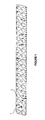
Figure 1 is a perspective view showing an illustrative embodiment of a bone plate of the present invention. -
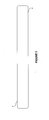
Figure 2 is a bottom view of the bone plate ofFigure 1 . -
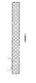
Figure 3 is a top view of the bone plate ofFigure 1 . -
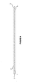
Figure 4 is a side view of the bone plate ofFigure 1 . -
Figure 5 is a cross-sectional view focusing on a single countersink of the bone plate ofFigure 1 . -
Figure 6 is an alternative embodiment of the bone plate ofFigure 1 . - In a first embodiment, illustrated in
Figures 1-5 , abone plate 1 includes a plurality ofcountersinks 2 formed on atop surface 3 of thebone plate 1. Theplate 1, as shown inFigure 2 , has asolid bottom surface 4. The solid bottom surface, coupled with the other solid portions ofplate 1, provides the plate with added strength and resistance to deformation than that of a similar plate with through holes formed through the plate in every portion where a countersink is shown. - In the embodiment shown in
Figures 1-5 , theplate 1 has an elongated, rectangular shape with rounded corners to minimize the risk of the implant causing irritation to a patient once implanted. Additionally, the perimeter of thetop surface 3 of theplate 1 is filleted 5 to reduce any sharp edges formed on the plate. Thecountersinks 2 are shown in rows and columns equally spaced apart. The plurality of countersinks formed on the plate provides the surgeon with the option to choose the screw fixation points intaoperatively. In other words, instead of including a plurality of fully formed holes, theplate 1 includes thecountersinks 2 that serve as preformed areas that can be utilized as fixation points. - More particularly, as shown in
Figures 4 and5 , thecountersinks 2 extend from thetop surface 3 toward thebottom surface 4 of theplate 1, but not entirely through theplate 1. Aplate thickness 7 can be increased to improve overall strength of the plate, or decreased to reduce the volume of foreign material introduced into the body of a patient. In addition, it is contemplated to increase or decrease the overall size and/or depth of thecountersinks 2 to increase the overall strength of the plate. The depth of each countersink could also be increased or decreased in selected regions of the bone plate to create regions of greater strength. - The
countersinks 2 shown inFigure 5 have a hemispherical shape to match the underside of a bone screw. However, other shapes are also contemplated such as a flat bottom, or other shape as necessary to match the underside of the bone screw used in cooperation with the plate. The diameter of the countersinks can be over-sized to enable the countersinks to receive a selection of screw heads, or have a diameter matching that of the specific screw heads to be used with the plate. The countersinks are not required to be of a singular shape. For example, some countersinks can be adapted to receive a screw head having a first shape while other countersinks are adapted to receive a screw head having a second shape. - The plate can be used in both adult and pediatric patients at any location where a bone needs to be fixed together and is preferably used in the craniofacial and mid-face skeleton. The plate can be manufactured to be resorbable by using a copolymer of polylactide and polyglycolide. The copolymer degrades and resorbs in vivo by hydrolysis into lactic and glycolic acid, which are then metabolized in the body to water (H2O) and carbon dioxide (CO2). A plate manufactured from the aforementioned copolymer is also malleable when sufficiently heated. The plate can be inserted into a heater, preferably a water bath, having a temperature of at least 140° F for a maximum of 30 seconds. Once heated, the plate can be adjusted to match the contour of the bone to which the plate will be secured. The plate can also be trimmed after heating to adjust the length or width of the plate as desired thereby avoiding the implantation of unnecessary plate material into a patient. In a preferred embodiment, the plate is trimmed using surgical scissors.
-
Figure 6 shows another embodiment of abone plate 1a according to the current invention. In the embodiment shown, theplate 1a has three rows of countersinks. Theplate 1a gives a surgeon more locations to choose from when choosing a position for a screw. The surgeon can also increase the total number of screws implanted to ensure complete fixation of the plate to the bone. Other configurations of the countersinks are also possible. For example, more rows or columns of countersinks could be included. The countersink pattern could also be something other than straight rows and columns. The space between the countersinks could also be increased, reducing the total number of countersinks formed on the top surface of the plate. Likewise, it is contemplated to provide plates of many different shapes and/or sizes for specific applications. - In use, the appropriately sized (e.g., length, width, thickness) and shaped
bone plate 1 is first selected depending upon the bone or bones to be repaired. The selected plate is then placed into a heating apparatus, preferably a water bath, for up to 30 seconds. Once removed from the bath, the plate is malleable allowing it to be shaped to more closely match the contours of the bone to which it will be secured. After heating, the plate may also be trimmed to a desired length and/or shape by cutting with scissors or another cutting device. The surgeon can also trim the plate to a desired length after it has been attached to the bone. - Once the surgeon determines where to place the screws, screw holes can be drilled into the center of the selected countersinks and the bone can be tapped for the screw (preferably at the same time). Alternatively, the screws can be self-tapping, eliminating the need to tap the hole after drilling. After drilling the holes, the screw can be inserted until fully seated in the countersink and the bottom of the plate is secured against the bone.
- Although the invention herein has been described with reference to particular embodiments, it is to be understood that these embodiments are merely illustrative of the principles and applications of the present invention. It is therefore to be understood that numerous modifications may be made to the illustrative embodiments and that other arrangements may be devised without departing from the scope of the present invention as defined by the appended claims.
Claims (15)
- A bone plate comprising:a top surface;a bottom surface; anda plurality of countersinks formed in the top surface extending toward but not reaching the bottom surface;wherein the countersinks are configured to receive a screw head.
- The bone plate of claim 1, wherein the countersinks are positioned in at least one row and at least one column.
- The bone plate of claim 1 or 2, wherein the bone plate is formed of a polymeric material.
- The bone plate of claim 3, wherein the bone plate is pliable when heated.
- The bone plate of any of the preceding claims, further comprising filleted edges.
- The bone plate of any of the preceding claims, wherein at least one of the countersinks has a different depth than at least one other countersink to create an area with different bone plate strength characteristics.
- The bone plate of claim 6, wherein at least one of the countersinks has a different shape than at least one other countersink to receive a different shaped screw head.
- A method of implanting a bone plate having a plurality of countersinks formed in a top surface extending toward but not reaching a bottom surface of the bone plate comprising:placing a bone plate against a surface;drilling a screw hole into the bone plate at a countersink; andinserting a screw into the screw hole to secure the bone plate to the surface.
- The method of claim 8, further comprising heating the bone plate until pliable and manipulating the bone plate to match a contour of the surface.
- The method of claim 8 or 9, wherein the screw is self tapping and taps the surface.
- The method of any of claims 8 to 10, wherein the drilling step includes drilling a plurality of screw holes and the inserting step includes inserting a plurality of screws into the screw holes.
- The method of any of claims 8 to 11, further comprising trimming the bone plate.
- The method of any of claims 8 to 12, wherein the inserting a screw step comprises inserting a screw until a top surface of a screw head is aligned with the top surface of the bone plate.
- A bone plate comprising:an elongated base member having at least one filleted edge;wherein the elongated member is flexible when heated;at least one row and at least one column of countersinks formed on an upper surface of the elongated member and extending toward a lower surface of the elongated member but not extending completely therethrough; andwherein the countersinks allow a top surface of a screw head to be coplanar with the upper surface of the elongated member when fully inserted.
- The bone plate of claim 14, wherein the countersinks have at least one of a hemispherical, rectangular, or frustoconical shape.
Applications Claiming Priority (1)
| Application Number | Priority Date | Filing Date | Title |
|---|---|---|---|
| US201461982640P | 2014-04-22 | 2014-04-22 |
Publications (1)
| Publication Number | Publication Date |
|---|---|
| EP2957247A1 true EP2957247A1 (en) | 2015-12-23 |
Family
ID=53039158
Family Applications (1)
| Application Number | Title | Priority Date | Filing Date |
|---|---|---|---|
| EP15001194.8A Ceased EP2957247A1 (en) | 2014-04-22 | 2015-04-22 | Plates with countersinks |
Country Status (2)
| Country | Link |
|---|---|
| US (1) | US9987063B2 (en) |
| EP (1) | EP2957247A1 (en) |
Families Citing this family (3)
| Publication number | Priority date | Publication date | Assignee | Title |
|---|---|---|---|---|
| WO2011154891A2 (en) * | 2010-06-07 | 2011-12-15 | Carbofix Orthopedics Ltd. | Composite material bone implant and methods |
| EP2957247A1 (en) * | 2014-04-22 | 2015-12-23 | Stryker European Holdings I, LLC | Plates with countersinks |
| US11389209B2 (en) * | 2019-07-19 | 2022-07-19 | Medos International Sarl | Surgical plating systems, devices, and related methods |
Citations (10)
| Publication number | Priority date | Publication date | Assignee | Title |
|---|---|---|---|---|
| DE8610858U1 (en) * | 1986-04-21 | 1986-06-12 | Wolter, Dietmar, Prof. Dr., 2000 Hamburg | Bone plate assembly |
| US4794918A (en) * | 1985-05-06 | 1989-01-03 | Dietmar Wolter | Bone plate arrangement |
| US5397363A (en) * | 1992-08-11 | 1995-03-14 | Gelbard; Steven D. | Spinal stabilization implant system |
| WO1999021502A1 (en) * | 1997-10-24 | 1999-05-06 | Bray Robert S Jr | Bone plate and bone screw guide mechanism |
| RU2160067C1 (en) * | 1999-11-04 | 2000-12-10 | Научно-исследовательский центр Татарстана "Восстановительная травматология и ортопедия" | Device for performing posterior spondylodesis |
| WO2004032726A2 (en) * | 2002-10-11 | 2004-04-22 | Abdou M Samy | Distraction screw for skeletal surgery and method of use |
| CN202069675U (en) * | 2011-05-22 | 2011-12-14 | 王蓉兰 | Static fixing plate for hip bone fracture |
| US20120123539A1 (en) * | 2010-11-17 | 2012-05-17 | Hightower Charles D | Moldable cushion for implants |
| EP2474278A2 (en) * | 2011-01-10 | 2012-07-11 | Ascension Orthopedics, Inc. | Bone plate system for repair of proximal humeral fracture |
| US20130204304A1 (en) * | 2012-02-03 | 2013-08-08 | Genesis Facture Care Inc. | Bone plate for elastic osteosynthesis |
Family Cites Families (52)
| Publication number | Priority date | Publication date | Assignee | Title |
|---|---|---|---|---|
| CH613858A5 (en) * | 1977-04-22 | 1979-10-31 | Straumann Inst Ag | |
| CH645013A5 (en) * | 1980-04-14 | 1984-09-14 | Wenk Wilh Ag | Osteosynthetic COMPRESSION PLATE. |
| IT1132843B (en) * | 1980-09-15 | 1986-07-09 | Cise Spa | PLATE FOR JOINTS OF SEPARATE BONE PORTIONS FROM FRACTURE |
| FR2517536B1 (en) * | 1981-12-09 | 1986-12-12 | Zbikowski Juan | FUNCTIONAL FIXING DEVICE FOR OSTEO-SYNTHESIS USING COMPRESSION PLATES |
| US4905680A (en) * | 1986-10-27 | 1990-03-06 | Johnson & Johnson Orthopaedics, Inc. | Absorbable bone plate |
| US5057111A (en) | 1987-11-04 | 1991-10-15 | Park Joon B | Non-stress-shielding bone fracture healing device |
| US5304180A (en) * | 1992-01-17 | 1994-04-19 | Slocum D Barclay | Tibial osteotomy fixation plate |
| US5569250A (en) | 1994-03-01 | 1996-10-29 | Sarver; David R. | Method and apparatus for securing adjacent bone portions |
| JP3542133B2 (en) * | 1995-03-27 | 2004-07-14 | ジンテーズ アクチエンゲゼルシャフト,クール | Bone plate |
| AU6145998A (en) * | 1997-02-11 | 1998-08-26 | Gary Karlin Michelson | Skeletal plating system |
| US6221075B1 (en) | 1998-03-06 | 2001-04-24 | Bionx Implants Oy | Bioabsorbable, deformable fixation plate |
| US6533786B1 (en) | 1999-10-13 | 2003-03-18 | Sdgi Holdings, Inc. | Anterior cervical plating system |
| JP2002542875A (en) * | 1999-05-03 | 2002-12-17 | メダルティス・アクチェンゲゼルシャフト | Bone plate that can be blocked |
| DE29909025U1 (en) * | 1999-05-25 | 1999-11-04 | Lipat Consulting Ag Basel | Osteosynthetic bone plate |
| US6692503B2 (en) * | 1999-10-13 | 2004-02-17 | Sdgi Holdings, Inc | System and method for securing a plate to the spinal column |
| US6692498B1 (en) * | 2000-11-27 | 2004-02-17 | Linvatec Corporation | Bioabsorbable, osteopromoting fixation plate |
| US6890335B2 (en) * | 2001-08-24 | 2005-05-10 | Zimmer Spine, Inc. | Bone fixation device |
| US7862597B2 (en) * | 2002-08-22 | 2011-01-04 | Warsaw Orthopedic, Inc. | System for stabilizing a portion of the spine |
| WO2004045389A2 (en) * | 2002-11-19 | 2004-06-03 | Acumed Llc | Adjustable bone plates |
| US7722653B2 (en) * | 2003-03-26 | 2010-05-25 | Greatbatch Medical S.A. | Locking bone plate |
| WO2006091827A2 (en) * | 2005-02-25 | 2006-08-31 | Regents Of The University Of California | Device and template for canine humeral slide osteotomy |
| US7727266B2 (en) * | 2004-06-17 | 2010-06-01 | Warsaw Orthopedic, Inc. | Method and apparatus for retaining screws in a plate |
| US20060058796A1 (en) * | 2004-09-14 | 2006-03-16 | Hartdegen Vernon R | Compression brace |
| US8394130B2 (en) * | 2005-03-17 | 2013-03-12 | Biomet C.V. | Modular fracture fixation system |
| US8172886B2 (en) | 2004-12-14 | 2012-05-08 | Depuy Products, Inc. | Bone plate with pre-assembled drill guide tips |
| US20060195085A1 (en) * | 2005-02-01 | 2006-08-31 | Inion Ltd. | System and method for stabilizing spine |
| EP1861031B1 (en) * | 2005-03-24 | 2010-04-14 | Medartis AG | Bone plate |
| US20060276793A1 (en) * | 2005-05-26 | 2006-12-07 | Amedica Corporation | Bone fixation plate with self-locking screws |
| WO2007009124A2 (en) * | 2005-07-13 | 2007-01-18 | Acumed Llc | Bone plates with movable locking elements |
| US7670341B2 (en) * | 2005-12-16 | 2010-03-02 | Depuy Products, Inc. | Orthopaedic device with locking barrel |
| US7935126B2 (en) | 2006-03-20 | 2011-05-03 | Depuy Products, Inc. | Bone plate shaping system |
| FI119177B (en) * | 2006-05-05 | 2008-08-29 | Bioretec Oy | Bioabsorbable, deformable fixation material and implants |
| AU2007250537A1 (en) * | 2006-05-17 | 2007-11-22 | Gordon Slater | Ankle fusion plate |
| EP2124785A1 (en) * | 2006-12-19 | 2009-12-02 | Small Bone Innovations, Inc. | Locking fixation system and lag tool |
| US20090254126A1 (en) * | 2008-04-04 | 2009-10-08 | Skeletal Dynamics Llc | Compression/distraction osteotomy system, plate, method, drill guide and saw guide |
| US8906076B2 (en) * | 2008-10-17 | 2014-12-09 | Osteomed Llc | Angulated locking plate and screw |
| US8444679B2 (en) * | 2008-11-24 | 2013-05-21 | Mbd Medical Llc | Clavicle plate and screws |
| US8403966B2 (en) * | 2008-11-24 | 2013-03-26 | Mbd Medical Llc | Clavicle plate and screws |
| US20100168799A1 (en) * | 2008-12-29 | 2010-07-01 | Schumer Evan D | Ulnar osteotomy plate including increased compression |
| WO2010111350A1 (en) * | 2009-03-24 | 2010-09-30 | Stabiliz Orthopedics, LLC | Orthopedic fixation device with bioresorbable layer |
| US8529608B2 (en) * | 2009-04-28 | 2013-09-10 | Osteomed Llc | Bone plate with a transfixation screw hole |
| US8808333B2 (en) * | 2009-07-06 | 2014-08-19 | Zimmer Gmbh | Periprosthetic bone plates |
| US8696715B2 (en) * | 2010-06-17 | 2014-04-15 | Chris Sidebotham | Low profile medical locking plate and bone screw design for bone fractures |
| US8956393B2 (en) * | 2010-07-06 | 2015-02-17 | Luis Edgardo Ramos Maza | Devices, systems, and methods for acetabulum repair |
| US20120203227A1 (en) * | 2011-02-08 | 2012-08-09 | Christopher Harris Martin | Low profile dorsal plate |
| US20130018424A1 (en) * | 2011-07-13 | 2013-01-17 | Michael Subik | Osteotomy and arthrodesis treatment system |
| FI125678B (en) * | 2011-08-26 | 2016-01-15 | Bioretec Oy | BIOABSORABLE, ORIENTED, DEFORMABLE FIXATION MATERIAL AND DISC |
| US9060822B2 (en) * | 2011-12-28 | 2015-06-23 | Orthohelix Surgical Designs, Inc. | Orthopedic compression plate and method of surgery |
| WO2014019998A1 (en) * | 2012-07-30 | 2014-02-06 | Materialise Nv | Systems and methods for forming and utilizing bending maps for object design |
| EP2832309B1 (en) * | 2013-07-31 | 2018-03-07 | Biedermann Technologies GmbH & Co. KG | Implant for bones or vertebrae with self-constrained flexibility |
| EP2957247A1 (en) * | 2014-04-22 | 2015-12-23 | Stryker European Holdings I, LLC | Plates with countersinks |
| EP3285671A4 (en) * | 2015-04-21 | 2018-12-12 | MWI Veterinary Supply Co. | Tplo bone plate |
-
2015
- 2015-04-22 EP EP15001194.8A patent/EP2957247A1/en not_active Ceased
- 2015-04-22 US US14/693,109 patent/US9987063B2/en active Active
Patent Citations (10)
| Publication number | Priority date | Publication date | Assignee | Title |
|---|---|---|---|---|
| US4794918A (en) * | 1985-05-06 | 1989-01-03 | Dietmar Wolter | Bone plate arrangement |
| DE8610858U1 (en) * | 1986-04-21 | 1986-06-12 | Wolter, Dietmar, Prof. Dr., 2000 Hamburg | Bone plate assembly |
| US5397363A (en) * | 1992-08-11 | 1995-03-14 | Gelbard; Steven D. | Spinal stabilization implant system |
| WO1999021502A1 (en) * | 1997-10-24 | 1999-05-06 | Bray Robert S Jr | Bone plate and bone screw guide mechanism |
| RU2160067C1 (en) * | 1999-11-04 | 2000-12-10 | Научно-исследовательский центр Татарстана "Восстановительная травматология и ортопедия" | Device for performing posterior spondylodesis |
| WO2004032726A2 (en) * | 2002-10-11 | 2004-04-22 | Abdou M Samy | Distraction screw for skeletal surgery and method of use |
| US20120123539A1 (en) * | 2010-11-17 | 2012-05-17 | Hightower Charles D | Moldable cushion for implants |
| EP2474278A2 (en) * | 2011-01-10 | 2012-07-11 | Ascension Orthopedics, Inc. | Bone plate system for repair of proximal humeral fracture |
| CN202069675U (en) * | 2011-05-22 | 2011-12-14 | 王蓉兰 | Static fixing plate for hip bone fracture |
| US20130204304A1 (en) * | 2012-02-03 | 2013-08-08 | Genesis Facture Care Inc. | Bone plate for elastic osteosynthesis |
Also Published As
| Publication number | Publication date |
|---|---|
| US9987063B2 (en) | 2018-06-05 |
| US20150297273A1 (en) | 2015-10-22 |
Similar Documents
| Publication | Publication Date | Title |
|---|---|---|
| JP6353519B2 (en) | Variable angle screws, plates and systems | |
| CN107847251B (en) | Locked bone implant | |
| JP6625573B2 (en) | First metacarpal plate locking | |
| US10582958B2 (en) | Bone fixation plate | |
| US20080009872A1 (en) | Resorbable surgical fixation device | |
| EP2630935B1 (en) | Glenoid extension block | |
| US20170209189A9 (en) | Locking Plate with Screw Fixation from Opposite Cortex | |
| JP2007530140A (en) | Bone fixation implant | |
| US20100016901A1 (en) | Bone screw retaining system | |
| EP1707139A1 (en) | Mid-foot fixation plate | |
| US20170100177A1 (en) | Screw fixing apparatus | |
| US20150230839A1 (en) | Shark Staple | |
| US9987063B2 (en) | Plates with countersinks | |
| EP3209230B1 (en) | Apparatus for bone fixation | |
| US20200237407A1 (en) | Strut Plate And Cabling System | |
| EP3629959B1 (en) | Acromioclavicular hook plate | |
| JP2018526148A (en) | Perforated tissue matrix | |
| US9839456B2 (en) | Anterolateral calcaneal plate | |
| US20220175427A1 (en) | Suprapectineal Quadrilateral Bone Plating System and Methods of Making and Using Same | |
| US20060082015A1 (en) | Surgical implant shaping instrument, surgical system and method | |
| US11197703B2 (en) | Fixation article for an implant | |
| CN110292432B (en) | Variable angle locking rotary correcting plate | |
| CN115553898B (en) | Module combined type internal fixation device suitable for anterior atlas internal fixation | |
| CN219461548U (en) | Laminoplasty prosthesis | |
| EP2995270A1 (en) | The set of bone plate and bone screw used to stabilize fractures |
Legal Events
| Date | Code | Title | Description |
|---|---|---|---|
| PUAI | Public reference made under article 153(3) epc to a published international application that has entered the european phase |
Free format text: ORIGINAL CODE: 0009012 |
|
| AK | Designated contracting states |
Kind code of ref document: A1 Designated state(s): AL AT BE BG CH CY CZ DE DK EE ES FI FR GB GR HR HU IE IS IT LI LT LU LV MC MK MT NL NO PL PT RO RS SE SI SK SM TR |
|
| AX | Request for extension of the european patent |
Extension state: BA ME |
|
| 17P | Request for examination filed |
Effective date: 20160609 |
|
| STAA | Information on the status of an ep patent application or granted ep patent |
Free format text: STATUS: EXAMINATION IS IN PROGRESS |
|
| 17Q | First examination report despatched |
Effective date: 20170217 |
|
| STAA | Information on the status of an ep patent application or granted ep patent |
Free format text: STATUS: THE APPLICATION HAS BEEN REFUSED |
|
| STAA | Information on the status of an ep patent application or granted ep patent |
Free format text: STATUS: THE APPLICATION HAS BEEN REFUSED |
|
| 18R | Application refused |
Effective date: 20171214 |