EP2955835A1 - Short circuit detection circuit and short circuit detection method for multi-phase rectifier at frequency domain - Google Patents
Short circuit detection circuit and short circuit detection method for multi-phase rectifier at frequency domain Download PDFInfo
- Publication number
- EP2955835A1 EP2955835A1 EP14172171.2A EP14172171A EP2955835A1 EP 2955835 A1 EP2955835 A1 EP 2955835A1 EP 14172171 A EP14172171 A EP 14172171A EP 2955835 A1 EP2955835 A1 EP 2955835A1
- Authority
- EP
- European Patent Office
- Prior art keywords
- signal
- short circuit
- fwr
- signals
- circuit detection
- Prior art date
- Legal status (The legal status is an assumption and is not a legal conclusion. Google has not performed a legal analysis and makes no representation as to the accuracy of the status listed.)
- Granted
Links
- 238000001514 detection method Methods 0.000 title claims abstract description 86
- 238000001228 spectrum Methods 0.000 claims abstract description 48
- 238000004804 winding Methods 0.000 claims description 23
- 239000007858 starting material Substances 0.000 claims description 2
- 238000001914 filtration Methods 0.000 claims 4
- 238000010586 diagram Methods 0.000 description 9
- 238000004146 energy storage Methods 0.000 description 8
- 230000006698 induction Effects 0.000 description 8
- 230000005355 Hall effect Effects 0.000 description 7
- 238000000034 method Methods 0.000 description 5
- 230000002159 abnormal effect Effects 0.000 description 3
- 230000009268 pathologic speech processing Effects 0.000 description 2
- 208000032207 progressive 1 supranuclear palsy Diseases 0.000 description 2
- 238000006243 chemical reaction Methods 0.000 description 1
- 230000000694 effects Effects 0.000 description 1
- 230000005674 electromagnetic induction Effects 0.000 description 1
- 238000005259 measurement Methods 0.000 description 1
- 238000000691 measurement method Methods 0.000 description 1
- 238000012986 modification Methods 0.000 description 1
- 230000004048 modification Effects 0.000 description 1
- 238000012545 processing Methods 0.000 description 1
- 238000011160 research Methods 0.000 description 1
Images


Classifications
-
- H—ELECTRICITY
- H02—GENERATION; CONVERSION OR DISTRIBUTION OF ELECTRIC POWER
- H02M—APPARATUS FOR CONVERSION BETWEEN AC AND AC, BETWEEN AC AND DC, OR BETWEEN DC AND DC, AND FOR USE WITH MAINS OR SIMILAR POWER SUPPLY SYSTEMS; CONVERSION OF DC OR AC INPUT POWER INTO SURGE OUTPUT POWER; CONTROL OR REGULATION THEREOF
- H02M7/00—Conversion of ac power input into dc power output; Conversion of dc power input into ac power output
- H02M7/02—Conversion of ac power input into dc power output without possibility of reversal
- H02M7/04—Conversion of ac power input into dc power output without possibility of reversal by static converters
- H02M7/06—Conversion of ac power input into dc power output without possibility of reversal by static converters using discharge tubes without control electrode or semiconductor devices without control electrode
-
- H—ELECTRICITY
- H02—GENERATION; CONVERSION OR DISTRIBUTION OF ELECTRIC POWER
- H02H—EMERGENCY PROTECTIVE CIRCUIT ARRANGEMENTS
- H02H3/00—Emergency protective circuit arrangements for automatic disconnection directly responsive to an undesired change from normal electric working condition with or without subsequent reconnection ; integrated protection
- H02H3/02—Details
- H02H3/04—Details with warning or supervision in addition to disconnection, e.g. for indicating that protective apparatus has functioned
-
- H—ELECTRICITY
- H02—GENERATION; CONVERSION OR DISTRIBUTION OF ELECTRIC POWER
- H02H—EMERGENCY PROTECTIVE CIRCUIT ARRANGEMENTS
- H02H7/00—Emergency protective circuit arrangements specially adapted for specific types of electric machines or apparatus or for sectionalised protection of cable or line systems, and effecting automatic switching in the event of an undesired change from normal working conditions
- H02H7/10—Emergency protective circuit arrangements specially adapted for specific types of electric machines or apparatus or for sectionalised protection of cable or line systems, and effecting automatic switching in the event of an undesired change from normal working conditions for converters; for rectifiers
- H02H7/12—Emergency protective circuit arrangements specially adapted for specific types of electric machines or apparatus or for sectionalised protection of cable or line systems, and effecting automatic switching in the event of an undesired change from normal working conditions for converters; for rectifiers for static converters or rectifiers
- H02H7/125—Emergency protective circuit arrangements specially adapted for specific types of electric machines or apparatus or for sectionalised protection of cable or line systems, and effecting automatic switching in the event of an undesired change from normal working conditions for converters; for rectifiers for static converters or rectifiers for rectifiers
- H02H7/1255—Emergency protective circuit arrangements specially adapted for specific types of electric machines or apparatus or for sectionalised protection of cable or line systems, and effecting automatic switching in the event of an undesired change from normal working conditions for converters; for rectifiers for static converters or rectifiers for rectifiers responsive to internal faults, e.g. by monitoring ripple in output voltage
Definitions
- the present invention relates to a short circuit detection circuit and short circuit detection method, in particular, to a short circuit detection circuit and a short circuit detection method for a multi-phase rectifier at alternator or Integrated Starter Generator (ISG) application.
- ISG Integrated Starter Generator
- a multi-phase rectifier of an alternator or an ISG is composed of many pairs of rectifying elements (e.g., diodes, MOSFETs, IGBTs, and etc.) to convert alternating current (AC) into direct current (DC) and then the direct current charges the battery connected to the multi-phase rectifier.
- the multi-phase rectifier becomes short, it generates excessive heat loss causing safety issues (e.g., damaging the whole alternator).
- the multi-phase rectifier's short circuit detection is necessary to raise the alarm for this abnormal condition.
- each current path of the multi-phase rectifier will be equipped with a short circuit detection element to detect whether the multi-phase rectifier is short circuit.
- short circuit detection methods for detecting whether a multi-phase rectifier is shorted out use either a sensing resistor or hall-effect sensor.
- the rectifying element as a diode.
- the sensing resistor R1 is configured in serial with the diode D1 so that the current I1 will flow through the diode D1 as well as the sensing resistor R1.
- the operational amplifier (op-amp) OP1 amplifies the voltage across the sensing resistor R1 to generate a detected signal Sd1.
- the comparator CP1 receives the detected signal Sd1 and compares the detected signal Sd1 with a reference signal Vref1 (i.e., the short circuit threshold voltage) to output a result signal OUT1, so as to determine whether the diode D1 is short.
- Vref1 i.e., the short circuit threshold voltage
- the sensing resistor R1 is required low resistance and high current operation generally and is usually expensive. For complete short circuit detection each multi-phase rectifier must have the above configuration respectively. So that, this will cause more power loss and cost.
- the hall-effect sensor HF is configured near a current path of a diode D2 to detect a current I2 of the current path using the magnetic field measurement method and then generate a detected signal Sd2.
- the comparator CP2 receives the detected signal Sd2 and compares the detected signal Sd2 with a reference signal Vref2 (i.e., the short circuit threshold voltage) to output a result signal OUT2 indicating whether the diode D2 is shorted out. Comparing the short circuit detection method using the hall-effect sensor with that of using the sensing resistor, the short circuit detection method using the hall-effect sensor has less power loss, but the hall-effect sensor HF is also expensive.
- the efficiency of the multi-phase rectifier can be enhanced greatly.
- the inventor strives via associated experience and research to present the instant disclosure, which can effectively improve the constraints described above.
- the instant disclosure provides a short circuit detection method/circuit for a three-phase (or more phases other than 3) rectifier at the alternator or the ISG application.
- the three-phase rectifier has three bridges connected in parallel. Each bridge has two rectifying elements connected in series. The connecting point between these two rectifying elements of the corresponding bridges is named as PSP (Phase Signal Point). Each PSP is between these two rectifying elements of the corresponding bridges. One rectifying element is connected between the PSP and ground. The other rectifying element is connected between the PSP and an alternator output terminal which is also a full-wave rectifier output terminal.
- each stator winding there are three stator windings in the alternator to generate three alternating current (AC) signals to the corresponding PSP during operation.
- One end of each stator winding is connected with each other.
- the other end (i.e., the alternator stator coil's output terminal) of each stator winding is connected to the corresponding PSP terminal.
- RPM alt is the operational speed of the alternator.
- the #pole pairs is the number of pole pairs in an alternator. Therefore, the frequency of each AC signal is same.
- the three-phase rectifier receives the three AC signals and rectifies the three AC signals to output a full-wave rectified (FWR) signal including a ripple frequency as a result of AC-to-DC conversion.
- the method/circuit detects the amplitude of the frequency of the AC signal (i.e., any one of the three AC signals) in the spectrum of the FWR signal.
- the detection scheme is to convert the FWR signal from time domain to frequency domain to generate the spectrum of the FWR signal and observe the present amplitude of the frequency of the AC signals.
- the amplitude of the frequency of the AC signal is negligible in the spectrum at the measurement point of FWR signal.
- the amplitude of the frequency of the AC signal will be significantly increase. Once this amplitude is greater than a preset reference (e.g., the experimental data based on the different Alternator), it can be concluded the existence of a short circuit condition among one of the rectifier element within the whole bridge set.
- the instant disclosure provides a short circuit detection circuit for a multi-phase rectifier.
- the multi-phase rectifier rectifies AC signals, each of which has a same frequency, to output a FWR signal, as mentioned above.
- the short circuit detection circuit includes an analyzing unit and a determination unit.
- the analyzing unit receives the FWR signal and analyzes a spectrum of the FWR signal in the frequency domain based on the same frequency of the AC signals to generate a detected signal indicating an amplitude of the same frequency of the AC signals.
- the determination unit is electrically connected to the analyzing unit, and compares the detected signal with a reference signal to determine whether the multi-phase rectifier has a short circuit condition.
- the determination unit receives the detected signal and the reference signal to determine whether the detected signal is greater than or equal to the reference signal.
- the spectrum analyzing unit outputs a result signal indicating that a short circuit condition exists among one of the rectifier elements within the bridge configured in the multi-phase rectifier.
- the instant disclosure also provides a short circuit detection method for a multi-phase rectifier.
- the multi-phase rectifier rectifies the received AC signals, each of which has a same frequency, to output a FWR signal as mentioned above.
- the short circuit detection method is as follows: receiving the FWR signal and analyzing a spectrum of the FWR signal in the frequency domain based on the same frequency of the AC signals to generate a detected signal indicating the amplitude of the same frequency of the AC signals; and receiving the detected signal and a reference signal to determine whether the detected signal is greater than or equal to the reference signal.
- the detection method includes a step of outputting a result signal indicating that a short circuit condition exists among one of the rectifier elements within the bridges configured in the multi-phase rectifier.
- the short circuit detection circuit and the short circuit detection method are used for detecting conditions of the spectrum of the FWR signal outputted from the multi-phase rectifier in the frequency domain, to determines whether the detected signal indicating the amplitude of the frequency of the AC signals is greater than or equal to the reference signal, so as to detect whether the short circuit condition exists among one of the rectifier elements within the bridges configured in the multi-phase rectifier. Therefore, the short circuit detection circuit and the short circuit detection method do not have the requirement of configuring the short circuit detection element (e.g., the sensing resistor or the hall-effect sensor) on each current path, so that the power loss and the cost can be reduced effectively.
- the short circuit detection element e.g., the sensing resistor or the hall-effect sensor
- FIG. 2A shows a diagram of a three-phase alternator in accordance with an embodiment of the instant disclosure.
- the three-phase alternator 1 has a three-phase rectifier 10, an induction coil 20, an energy storage device 30 (or a load), and a short circuit detection circuit 100.
- the three-phase rectifier 10 has three bridges connected in parallel, respectively, first bridge 11a, second bridge 11b and third bridge 11c. One end of the first bridge 11a, one end of the second bridge 11b, and one end of the third bridge 11c are grounded. Another end of the first bridge 11a, another end of the second bridge 11b, and another end of the third bridge 11c are connected to a full-wave rectifier output terminal FO.
- the full-wave rectifier output terminal FO is connected to the energy storage device 30.
- each bridge 11a, 11b, and 11c has two diodes Dd1 and Dd2 connected in series.
- the anode of the diode Dd1 is grounded
- the cathode of the diode Dd1 is connected to the anode of the diode Dd2
- the cathode of the diode Dd2 is connected to the full-wave rectifier output terminal FO.
- a PSP Tb1 is between the two diodes Dd1 and Dd2 of the bridge 11a
- a PSP Tb2 is between the two diodes Dd1 and Dd2 of the bridge 11b
- a PSP Tb3 is between the two diodes Dd1 and Dd2 of the bridge 11c.
- the two diodes Dd1 and Dd2 merely serve to illustrate an example of rectifying elements for rectification, and the rectifying elements can also be MOSFETs, IGBTs and etc. The instant disclosure is not limited thereto.
- the PSPs Tb1, Tb2, and Tb3 receive the AC signals having the same frequency and then the three-phase rectifier 10 rectifies the AC signals to generate a FWR signal Sr1 to the energy storage device 30.
- the AC signals have three sine wave signals SI1, SI2, and SI3 and the three sine wave signals SI1, SI2, and SI3 have the same frequency.
- the phase difference among the sine wave signals SI1, SI2, and SI3 is 120 degrees.
- the three-phase rectifier 10 rectifies the sine wave signals SI1, SI2, and SI3 to produce six half-waved ripples in one period T, i.e., the FWR signal Sr1, so that the energy storage device 30 can be charged by the FWR signal Sr1.
- those skilled in the art are able to understand generation of the FWR signal Sr1 through the three-phase rectifier 10, and further descriptions are hereby omitted.
- the frequency of the three sine wave signals SI1, SI2, and SI3 can be calculated by a frequency detector or through other method.
- the operational speed of the alternator and the number of pole pairs in an alternator e.q, 18 pole alternator has 9 pole pairs
- the operational speed of the alternator can also calculated by the aforementioned equation for other applications.
- the AC signals are generated by the induction coil 20 and the induction coil 20 can be induced by electromagnetic induction to generate the AC signals.
- the induction coil 20 has three stator windings displaced 120 degrees from each other, respectively, a first stator winding 21a, a second stator winding 21b, and a third stator winding 21c to form a "Y" configuration.
- One end of the first stator winding 21a, one end of the second stator winding 21b, and one end of the third stator winding 21c are connected with each other.
- Another end of the first stator winding 21a is connected to the PSP Tb1 of the bridge 11a.
- Another end of the second stator winding 21b is connected to the PSP Tb2 of the bridge 11b.
- the induction coil 20 can also be configured to be other windings, such as "delta" configuration or "star” configuration, and the instant disclosure is not limited thereto.
- the three-phase alternator 1 includes a short circuit detection circuit 100 connected between the three-phase rectifier 10 and the energy storage device 30.
- the short circuit detection circuit 100 receives the FWR signal Sr1 and an AC signal Si1 to determine whether the three-phase rectifier 10 has the short circuit condition existing among one of the rectifier elements within the bridges.
- the short circuit detection circuit 100 includes a spectrum analyzing unit 110 and a determination unit 120.
- the spectrum analyzing unit 110 receives the FWR signal Sr1 and analyzes a spectrum of the FWR signal Sr1 in the frequency domain based on the frequency of the AC signal Si1 to generate a detected signal Vd1 indicating the amplitude of the frequency of the AC signal Si1.
- the determination unit 120 is electrically connected to the spectrum analyzing unit 110.
- the determination unit 120 receives the detected signal Vd1 and a reference signal Vf1 to determine whether the detected signal Vd1 is greater than or equal to the reference signal Vf1.
- the determination unit 120 determines that the detected signal Vd1 is greater than or equal to the reference signal Vf1
- the determination unit 120 outputs a result signal SO1 to indicate that the short circuit condition exists among one of the rectifier elements within the bridges, such as the diode D1 of the bridge 11b is shorted out.
- the short circuit detection circuit 100 detects that the amplitude of the frequency of the AC signal Si1 significantly increase in the spectrum of the FWR signal Sr1 in the frequency domain.
- the determination unit 120 determines that the detected signal Vd1 is less than the reference signal Vf1, the determination unit 120 outputs no signal to indicate that the short circuit condition does not exist among one of the rectifier elements within the bridges at present. This means that when the three-phase rectifier 10 does not have any shorted diodes in the bridges 11a ⁇ 11c, the short circuit detection circuit 100 detects that the amplitude of the frequency of the AC signal Si1 is too small and can be ignored because the amplitude of the frequency of the AC signal Si1 is similar to the noise signal in the spectrum of the FWR signal Sr1.
- the spectrum analyzing unit 110 includes an analog-to-digital (AD) converter 112, a spectrum calculator 114, and a frequency selector 116.
- the AD converter 112 is connected to the spectrum calculator 114.
- the spectrum calculator 114 is connected to the frequency selector 116.
- the AD converter 112 receives the FWR signal Sr1 and digitizes the FWR signal Sr1 to generate the digital FWR signal Sr1.
- the spectrum calculator 114 calculates the spectrum of the digital FWR signal Sr1 to acquire the spectrum of the digital FWR signal Sr1 having every frequency.
- the frequency selector 116 selects the frequency of the AC signal Si1 in the spectrum of the FWR signal Sr1 (i.e. selects the specific frequency band in the spectrum of the FWR signal Sr1 based on the AC signal Si1) to output the detected signal Vd1 indicating the amplitude of the frequency of the AC signal Si1.
- the determination unit 120 is a digital comparator having an A end and a B end.
- the A end receives the detected signal Vd1.
- the B end receives the reference signal Vf1.
- the digital comparator outputs the result signal SO1 according to the detected signal Vd1 and the reference signal Vf1.
- the determination unit 120 when the determination unit 120 outputs the high-level result signal SO1 indicating that the detected signal Vd1 is greater than or equal to the reference signal Vf1, such as 5V, it means that the three-phase rectifier 10 has the short circuit condition existing among one of the rectifier elements within the bridges.
- the determination unit 120 outputs no signal (e.g., the low-level result signal SO1 indicating that the detected signal Vd1 is less than the reference signal Vf1, such as 0V), it means that the three-phase rectifier 10 does not have the short circuit condition existing among one of the rectifier elements within the bridges.
- the determination unit 120 not limited to, but preferably made by the digital comparator, can also use another element to generate the result signal SO1.
- the instant disclosure may be generalized as a short circuit detection method, which is adapted for a short circuit detection circuit.
- FIG. 2D shows a flowchart of a short circuit detection method in accordance with an embodiment of the instant disclosure.
- the spectrum analyzing unit 110 receives the FWR signal Sr1 and analyzes a spectrum of the FWR signal Sr1 in the frequency domain based on the frequency of the AC signal Si1 to generate the detected signal Vd1 indicating the amplitude of the frequency of the AC signal Si1 (Step S210).
- the determination unit 120 receives the detected signal Vd1 and the reference signal Vf1 to determine whether the detected signal Vd1 is greater than or equal to the reference signal Vf1, so as to analyze the present condition of the rectifier elements within the bridges (Step S220 and S230).
- the determination unit 120 determines that the detected signal Vd1 is greater than or equal to the reference signal Vf1, the three-phase rectifier 10 is in the abnormal operation.
- the determination unit 120 outputs a result signal SO1 indicating that the short circuit condition exists among one of the rectifier elements within the bridges, which means there is at least one shorted diode in the bridges 11a-11c of the three-phase rectifier 10 (Step S240).
- the determination unit 120 determines that the detected signal Vd1 is less than the reference signal Vf1, the three-phase rectifier 10 is in the normal operation.
- the determination unit 120 outputs no signal indicating the short circuit condition does not exist among one of the rectifier elements within the bridges, which means there is no shorted diode in the bridges 11a-11c of the three-phase rectifier 10 (Step S250).
- the short circuit detection circuit 100 can not only be adapted for the three-phase alternator but also be adapted for the multi-phase alternator.
- the instant embodiment is not limited thereto.
- the multi-phase alternator 1A has a multi-phase rectifier 10A, an induction coil 20A, a power supply 30A, and a short circuit detection circuit 100A.
- the multi-phase rectifier 10A has N bridges connected in parallel, wherein N is an integer greater than or equal to 2 (e.g., the three bridges 11a-11c in FIG. 2A ).
- Each bridge has two rectifying elements connected in series and a PSP connected between the two rectifying elements of the corresponding bridges (e.g., the diodes Dd1 and Dd2 of the three bridges 11a-11c in FIG. 2A ).
- Each PSP e.g., the PSPs Tb1-Tb3 in FIG. 2A
- receives a AC signal having a same frequency and the multi-phase rectifier 10A outputs a FWR signal Sr1A to the short circuit detection circuit 100A and the energy storage device 30A (or a load).
- the rectifying elements can be diode, MOSFET, IGBT and etc. The instant disclosure is not limited thereto.
- the related structures and operation method associated with the multi-phase rectifier 10A, the induction coil 20A, the energy storage device 30A, and the short circuit detection circuit 100A are essentially the same as the three-phase rectifier 10, the induction coil 20, the energy storage device 30, and the short circuit detection circuit 100 described in the aforementioned embodiment, and further descriptions are hereby omitted.
- the determination unit of the short circuit detection circuit 100A determines that the detected signal is greater than or equal to the reference signal, the determination unit of the short circuit detection circuit 100A outputs a result signal indicating that a short circuit condition exists among one of the rectifier elements within the bridges.
- the determination unit of the short circuit detection circuit 100A determines that the detected signal is less than the reference signal
- the determination unit of the short circuit detection circuit 100A outputs a result signal indicating that the short circuit condition does not exist among one of the rectifier elements within the bridges.
- the short circuit detection circuit 100A is used for detecting conditions of the spectrum of the FWR signal Sr1A outputted from the multi-phase rectifier 10A in the frequency domain, to determines whether the detected signal indicating the amplitude of the frequency of the AC signal is greater than or equal to the reference signal, so as to detect whether the short circuit condition exists among one of the rectifier elements within the bridges.
- the short circuit detection circuit 200 receives the FWR signal Sr2 transmitted from a multi-phase rectifier and determines whether the multi-phase rectifier has the shorted rectifying element.
- the short circuit detection circuit 200 has a spectrum analyzing unit 210 and a determination unit 220 connected to the spectrum analyzing unit 210.
- the spectrum analyzing unit 210 includes an AD converter 212, a digital filter 214, and a frequency selector 216.
- the digital filter 214 is connected to the frequency selector 216 and the AD converter 212.
- the frequency selector 216 generates a select signal Vi2 according to the frequency of the AC signal Si2. For example, the frequency selector 216 generates the select signal Vi2 indicating the frequency of the AC signal Si2.
- the AD converter 212 receives the FWR signal Sr2 and digitizes the FWR signal Sr2 to generate the digital FWR signal Sr2.
- the digital filter 214 filters the digital FWR signal Sr2 based on the select signal Vi2 to output the detected signal Vd2 indicating the amplitude of the frequency of the AC signal Si2.
- the determination unit 220 is a digital comparator having an A end and a B end. The A end receives the detected signal Vd2. The B end receives the reference signal Vf2. The digital comparator outputs the result signal SO2 according to the detected signal Vd2 and the reference signal Vf2.
- the determination unit 220 when the determination unit 220 outputs a high-level result signal SO2 indicating that the detected signal Vd2 is greater than or equal to the reference signal Vf2, such as 5V, it means that the multi-phase rectifier has the short circuit condition existing among one of the rectifier elements within the bridges.
- the determination unit 220 outputs no signal (alternatively, a low-level result signal SO2 indicating that the detected signal Vd2 is less than the reference signal Vf2, such as 0V), it means that the multi-phase rectifier does not have the short circuit condition existing among one of the rectifier elements within the bridges.
- the short circuit detection circuit 200 can also analyze the power or other data of the digital FWR signal Sr2 and the frequency of the AC signal Si2, to determine whether the short circuit condition exists among one of the rectifier elements within the bridges, but the instant embodiment is not limited thereto.
- the determination unit 220 not limited to, preferably made by the digital comparator, can also include another element to generate the result signal SO2.
- the short circuit detection circuit 300 receives the FWR signal Sr3 transmitted from the multi-phase rectifier and determines whether the multi-phase rectifier has the shorted rectifying element.
- the short circuit detection circuit 300 has a spectrum analyzing unit 310 and a determination unit 320 connected to the spectrum analyzing unit 310.
- the spectrum analyzing unit 310 includes an analog filter 312 and a frequency selector 316 connected to the analog filter 312.
- the frequency selector 316 generates a select signal Vi3 according to the frequency of the AC signal Si3. For example, the frequency selector 316 generates the select signal Vi3 indicating the frequency of the AC signal Si3.
- the analog filter 312 receives the FWR signal Sr3 and the select signal Vi3 to filter the FWR signal Sr3 based on the select signal Vi3 to output the detected signal Vd3 indicating the amplitude of the frequency of the AC signal Si3 to the determination unit 320.
- the determination unit 320 may be an operational amplifier (op-amp) 320 having a non-inverting end, an inverting end, and an output end, wherein the non-inverting end receives the detected signal Vd3, the inverting end receives a reference signal Vf3, and the output end outputs the result signal SO3 according to the detected signal Vd3 and the reference signal Vf3, wherein the reference signal Vf3 is defined by the amplitude of the frequency of the AC signal Si3.
- op-amp operational amplifier
- the output end of the op-amp 320 outputs a high-level result signal SO3 indicating that the detected signal Vd3 is greater than or equal to the reference signal Vf3, such as 5V, it means that the multi-phase rectifier has the short circuit condition existing among one of the rectifier elements within the bridges.
- the determination unit 320 outputs no signal (alternatively, a low-level result signal SO3 indicating that the detected signal Vd3 is less than the reference signal Vf3, such as 0V), it means that the multi-phase rectifier does not have the short circuit condition existing among one of the rectifier elements within the bridges.
- the short circuit detection circuit 300 can also analyze the power or other data of the digital FWR signal Sr3 and the frequency of the AC signal Si3, to determine whether the short circuit condition exists among one of the rectifier elements within the bridges, but the instant embodiment is not limited thereto.
- the determination unit 320 not limited to, preferably made by the op-amp, can also include another element to generate the result signal SO3.
- the short circuit detection circuit and the short circuit detection method provided in the present invention are used for detecting conditions of the spectrum of the FWR signal outputted from the multi-phase rectifier in the frequency domain, and then determining whether the detected signal indicating the amplitude of the frequency of the AC signals is greater than or equal to the reference signal, so as to determine whether the short circuit condition exists among one of the rectifier elements within the bridges configured in the multi-phase rectifier. Therefore, the short circuit detection circuit and the short circuit detection method provided in the present invention do not have any requirements for configuring a short circuit detection element (e.g., the sensing resistor or the hall-effect sensor) on each current path for the conventional short circuit detection method, so that the power loss and the cost can be reduced effectively.
- a short circuit detection element e.g., the sensing resistor or the hall-effect sensor
Abstract
Description
- The present invention relates to a short circuit detection circuit and short circuit detection method, in particular, to a short circuit detection circuit and a short circuit detection method for a multi-phase rectifier at alternator or Integrated Starter Generator (ISG) application.
- A multi-phase rectifier of an alternator or an ISG is composed of many pairs of rectifying elements (e.g., diodes, MOSFETs, IGBTs, and etc.) to convert alternating current (AC) into direct current (DC) and then the direct current charges the battery connected to the multi-phase rectifier. When the multi-phase rectifier becomes short, it generates excessive heat loss causing safety issues (e.g., damaging the whole alternator). The multi-phase rectifier's short circuit detection is necessary to raise the alarm for this abnormal condition. In order to detect the multi-phase rectifier's short circuit, each current path of the multi-phase rectifier will be equipped with a short circuit detection element to detect whether the multi-phase rectifier is short circuit.
- Generally speaking, short circuit detection methods for detecting whether a multi-phase rectifier is shorted out use either a sensing resistor or hall-effect sensor. For clarity, the following regards the rectifying element as a diode. For one diode which is configured in a current path, as shown in
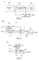
FIG. 1A , the sensing resistor R1 is configured in serial with the diode D1 so that the current I1 will flow through the diode D1 as well as the sensing resistor R1. Then the operational amplifier (op-amp) OP1 amplifies the voltage across the sensing resistor R1 to generate a detected signal Sd1. Next, the comparator CP1 receives the detected signal Sd1 and compares the detected signal Sd1 with a reference signal Vref1 (i.e., the short circuit threshold voltage) to output a result signal OUT1, so as to determine whether the diode D1 is short. Because the short circuit detection method has to add the additional sensing resistor R1 which is configured in the current path, it will cause (I12*R1) power loss in the current path. Furthermore, the sensing resistor R1 is required low resistance and high current operation generally and is usually expensive. For complete short circuit detection each multi-phase rectifier must have the above configuration respectively. So that, this will cause more power loss and cost. - Using the other method, as shown in
FIG. 1B , the hall-effect sensor HF is configured near a current path of a diode D2 to detect a current I2 of the current path using the magnetic field measurement method and then generate a detected signal Sd2. Next, the comparator CP2 receives the detected signal Sd2 and compares the detected signal Sd2 with a reference signal Vref2 (i.e., the short circuit threshold voltage) to output a result signal OUT2 indicating whether the diode D2 is shorted out. Comparing the short circuit detection method using the hall-effect sensor with that of using the sensing resistor, the short circuit detection method using the hall-effect sensor has less power loss, but the hall-effect sensor HF is also expensive. - Therefore, if the power loss and the cost can be reduced effectively during the processing of the short circuit detection method, the efficiency of the multi-phase rectifier can be enhanced greatly.
- To address the above issues, the inventor strives via associated experience and research to present the instant disclosure, which can effectively improve the constraints described above.
- The instant disclosure provides a short circuit detection method/circuit for a three-phase (or more phases other than 3) rectifier at the alternator or the ISG application. For the three-phase rectifier at the alternator, the three-phase rectifier has three bridges connected in parallel. Each bridge has two rectifying elements connected in series. The connecting point between these two rectifying elements of the corresponding bridges is named as PSP (Phase Signal Point). Each PSP is between these two rectifying elements of the corresponding bridges. One rectifying element is connected between the PSP and ground. The other rectifying element is connected between the PSP and an alternator output terminal which is also a full-wave rectifier output terminal.
- There are three stator windings in the alternator to generate three alternating current (AC) signals to the corresponding PSP during operation. One end of each stator winding is connected with each other. The other end (i.e., the alternator stator coil's output terminal) of each stator winding is connected to the corresponding PSP terminal. The frequency of each AC signal will keep at the same during one specific rotating period because the frequency of each AC signal can be calculated by the same equation as follows: ω= RPMalt*#pole pairs/60, wherein ω is the frequency of each AC signal. RPMalt is the operational speed of the alternator. The #pole pairs is the number of pole pairs in an alternator. Therefore, the frequency of each AC signal is same.
- The three-phase rectifier receives the three AC signals and rectifies the three AC signals to output a full-wave rectified (FWR) signal including a ripple frequency as a result of AC-to-DC conversion. The method/circuit detects the amplitude of the frequency of the AC signal (i.e., any one of the three AC signals) in the spectrum of the FWR signal. The detection scheme is to convert the FWR signal from time domain to frequency domain to generate the spectrum of the FWR signal and observe the present amplitude of the frequency of the AC signals.
- Under the normal operation, the amplitude of the frequency of the AC signal is negligible in the spectrum at the measurement point of FWR signal. However, if there is any occurrence of the short circuit at any of the rectifier elements (i.e., under the abnormal operation), the amplitude of the frequency of the AC signal will be significantly increase. Once this amplitude is greater than a preset reference (e.g., the experimental data based on the different Alternator), it can be concluded the existence of a short circuit condition among one of the rectifier element within the whole bridge set.
- Accordingly, the instant disclosure provides a short circuit detection circuit for a multi-phase rectifier. The multi-phase rectifier rectifies AC signals, each of which has a same frequency, to output a FWR signal, as mentioned above. The short circuit detection circuit includes an analyzing unit and a determination unit. The analyzing unit receives the FWR signal and analyzes a spectrum of the FWR signal in the frequency domain based on the same frequency of the AC signals to generate a detected signal indicating an amplitude of the same frequency of the AC signals. The determination unit is electrically connected to the analyzing unit, and compares the detected signal with a reference signal to determine whether the multi-phase rectifier has a short circuit condition.
- Specifically, the determination unit receives the detected signal and the reference signal to determine whether the detected signal is greater than or equal to the reference signal. When the determination unit determines that the detected signal is greater than or equal to the reference signal, the spectrum analyzing unit outputs a result signal indicating that a short circuit condition exists among one of the rectifier elements within the bridge configured in the multi-phase rectifier.
- The instant disclosure also provides a short circuit detection method for a multi-phase rectifier. The multi-phase rectifier rectifies the received AC signals, each of which has a same frequency, to output a FWR signal as mentioned above. The short circuit detection method is as follows: receiving the FWR signal and analyzing a spectrum of the FWR signal in the frequency domain based on the same frequency of the AC signals to generate a detected signal indicating the amplitude of the same frequency of the AC signals; and receiving the detected signal and a reference signal to determine whether the detected signal is greater than or equal to the reference signal. When the detected signal is greater than or equal to the reference signal, the detection method includes a step of outputting a result signal indicating that a short circuit condition exists among one of the rectifier elements within the bridges configured in the multi-phase rectifier.
- In summary, the short circuit detection circuit and the short circuit detection method are used for detecting conditions of the spectrum of the FWR signal outputted from the multi-phase rectifier in the frequency domain, to determines whether the detected signal indicating the amplitude of the frequency of the AC signals is greater than or equal to the reference signal, so as to detect whether the short circuit condition exists among one of the rectifier elements within the bridges configured in the multi-phase rectifier. Therefore, the short circuit detection circuit and the short circuit detection method do not have the requirement of configuring the short circuit detection element (e.g., the sensing resistor or the hall-effect sensor) on each current path, so that the power loss and the cost can be reduced effectively.
- In order to further understand the techniques, means and effects of the present invention, the following detailed descriptions and appended drawings are hereby referred to, such that and through which, the purposes, features and aspects of the present disclosure can be thoroughly and concretely appreciated; however, the appended drawings are merely provided for reference and illustration, without any intention to be used for limiting the present invention.
- The accompanying drawings are included to provide a further understanding of the present invention, and are incorporated in and constitute a part of this specification. The drawings illustrate exemplary embodiments of the present invention and, together with the description, serve to explain the principles of the present invention.
-
FIG. 1A shows a diagram of a conventional short circuit detection circuit of a current path flowing through a rectifying element. -
FIG. 1B shows a diagram of another conventional short circuit detection circuit of a current path flowing through a rectifying element. -
FIG. 2A shows a diagram of a three-phase alternator in accordance with an embodiment of the instant disclosure. -
FIG. 2B shows a waveform diagram of a three-phase alternator in accordance with an embodiment of the instant disclosure. -
FIG. 2C shows a diagram of a short circuit detection circuit in accordance with an embodiment of the instant disclosure. -
FIG. 2D shows a flowchart of a short circuit detection method in accordance with an embodiment of the instant disclosure. -
FIG. 3 shows a diagram of a multi-phase alternator in accordance with another embodiment of the instant disclosure. -
FIG. 4 shows a diagram of a short circuit detection circuit in accordance with another embodiment of the instant disclosure. -
FIG. 5 shows a diagram of a short circuit detection circuit in accordance with another embodiment of the instant disclosure. - Reference will now be made in detail to the exemplary embodiments of the present disclosure, examples of which are illustrated in the accompanying drawings. Wherever possible, the same reference numbers are used in the drawings and the description to refer to the same or like parts.
- Please refer to
FIG. 2A , which shows a diagram of a three-phase alternator in accordance with an embodiment of the instant disclosure. As shown inFIG. 2A , the three-phase alternator 1 has a three-phase rectifier 10, aninduction coil 20, an energy storage device 30 (or a load), and a shortcircuit detection circuit 100. The three-phase rectifier 10 has three bridges connected in parallel, respectively,first bridge 11a,second bridge 11b andthird bridge 11c. One end of thefirst bridge 11a, one end of thesecond bridge 11b, and one end of thethird bridge 11c are grounded. Another end of thefirst bridge 11a, another end of thesecond bridge 11b, and another end of thethird bridge 11c are connected to a full-wave rectifier output terminal FO. The full-wave rectifier output terminal FO is connected to theenergy storage device 30. - More specifically, each
bridge bridges bridge 11a, a PSP Tb2 is between the two diodes Dd1 and Dd2 of thebridge 11b, and a PSP Tb3 is between the two diodes Dd1 and Dd2 of thebridge 11c. It shall be noted that the two diodes Dd1 and Dd2 merely serve to illustrate an example of rectifying elements for rectification, and the rectifying elements can also be MOSFETs, IGBTs and etc. The instant disclosure is not limited thereto. - The PSPs Tb1, Tb2, and Tb3 receive the AC signals having the same frequency and then the three-
phase rectifier 10 rectifies the AC signals to generate a FWR signal Sr1 to theenergy storage device 30. Specifically, as shown inFIG. 2B , the AC signals have three sine wave signals SI1, SI2, and SI3 and the three sine wave signals SI1, SI2, and SI3 have the same frequency. The phase difference among the sine wave signals SI1, SI2, and SI3 is 120 degrees. Then the three-phase rectifier 10 rectifies the sine wave signals SI1, SI2, and SI3 to produce six half-waved ripples in one period T, i.e., the FWR signal Sr1, so that theenergy storage device 30 can be charged by the FWR signal Sr1. Moreover, those skilled in the art are able to understand generation of the FWR signal Sr1 through the three-phase rectifier 10, and further descriptions are hereby omitted. - It is worth to note that the frequency of the three sine wave signals SI1, SI2, and SI3 can be calculated by a frequency detector or through other method. For example, the operational speed of the alternator and the number of pole pairs in an alternator (e.q, 18 pole alternator has 9 pole pairs) are known. The frequency of each AC signal can be calculated by the following equation:

wherein ω is the frequency of each AC signal, RPMalt is an operational speed of the alternator, and the #pole pairs are the number of pole pairs in the alternator. The instant disclosure is not limited thereto. Similarly, when the frequency of the AC signal and the number of pole pairs in the alternator (e.g., 14 pole alternator has 7 pole pairs) are known, the operational speed of the alternator can also calculated by the aforementioned equation for other applications. - In the instant disclosure, the AC signals are generated by the
induction coil 20 and theinduction coil 20 can be induced by electromagnetic induction to generate the AC signals. Theinduction coil 20 has three stator windings displaced 120 degrees from each other, respectively, a first stator winding 21a, a second stator winding 21b, and a third stator winding 21c to form a "Y" configuration. One end of the first stator winding 21a, one end of the second stator winding 21b, and one end of the third stator winding 21c are connected with each other. Another end of the first stator winding 21a is connected to the PSP Tb1 of thebridge 11a. Another end of the second stator winding 21b is connected to the PSP Tb2 of thebridge 11b. Another end of the third stator winding 21c is connected to the PSP Tb3 of thebridge 11c. Theinduction coil 20 can also be configured to be other windings, such as "delta" configuration or "star" configuration, and the instant disclosure is not limited thereto. - In order to check whether the three-
phase rectifier 10 has a short circuit condition existing among one of the rectifier elements within the bridges, the three-phase alternator 1 includes a shortcircuit detection circuit 100 connected between the three-phase rectifier 10 and theenergy storage device 30. The shortcircuit detection circuit 100 receives the FWR signal Sr1 and an AC signal Si1 to determine whether the three-phase rectifier 10 has the short circuit condition existing among one of the rectifier elements within the bridges. - As shown in
FIG. 2C , the shortcircuit detection circuit 100 includes aspectrum analyzing unit 110 and adetermination unit 120. Thespectrum analyzing unit 110 receives the FWR signal Sr1 and analyzes a spectrum of the FWR signal Sr1 in the frequency domain based on the frequency of the AC signal Si1 to generate a detected signal Vd1 indicating the amplitude of the frequency of the AC signal Si1. Thedetermination unit 120 is electrically connected to thespectrum analyzing unit 110. Thedetermination unit 120 receives the detected signal Vd1 and a reference signal Vf1 to determine whether the detected signal Vd1 is greater than or equal to the reference signal Vf1. - When the
determination unit 120 determines that the detected signal Vd1 is greater than or equal to the reference signal Vf1, thedetermination unit 120 outputs a result signal SO1 to indicate that the short circuit condition exists among one of the rectifier elements within the bridges, such as the diode D1 of thebridge 11b is shorted out. This means that when the three-phase rectifier 10 has at least one shorted diode in thebridges 11a∼11c, the shortcircuit detection circuit 100 detects that the amplitude of the frequency of the AC signal Si1 significantly increase in the spectrum of the FWR signal Sr1 in the frequency domain. - When the
determination unit 120 determines that the detected signal Vd1 is less than the reference signal Vf1, thedetermination unit 120 outputs no signal to indicate that the short circuit condition does not exist among one of the rectifier elements within the bridges at present. This means that when the three-phase rectifier 10 does not have any shorted diodes in thebridges 11a∼11c, the shortcircuit detection circuit 100 detects that the amplitude of the frequency of the AC signal Si1 is too small and can be ignored because the amplitude of the frequency of the AC signal Si1 is similar to the noise signal in the spectrum of the FWR signal Sr1. - As shown in
FIG. 2C , in the instant disclosure, thespectrum analyzing unit 110 includes an analog-to-digital (AD)converter 112, aspectrum calculator 114, and afrequency selector 116. TheAD converter 112 is connected to thespectrum calculator 114. Thespectrum calculator 114 is connected to thefrequency selector 116. TheAD converter 112 receives the FWR signal Sr1 and digitizes the FWR signal Sr1 to generate the digital FWR signal Sr1. - The
spectrum calculator 114 calculates the spectrum of the digital FWR signal Sr1 to acquire the spectrum of the digital FWR signal Sr1 having every frequency. Thefrequency selector 116 selects the frequency of the AC signal Si1 in the spectrum of the FWR signal Sr1 (i.e. selects the specific frequency band in the spectrum of the FWR signal Sr1 based on the AC signal Si1) to output the detected signal Vd1 indicating the amplitude of the frequency of the AC signal Si1. - The
determination unit 120 is a digital comparator having an A end and a B end. The A end receives the detected signal Vd1. The B end receives the reference signal Vf1. The digital comparator outputs the result signal SO1 according to the detected signal Vd1 and the reference signal Vf1. - Therefore, when the
determination unit 120 outputs the high-level result signal SO1 indicating that the detected signal Vd1 is greater than or equal to the reference signal Vf1, such as 5V, it means that the three-phase rectifier 10 has the short circuit condition existing among one of the rectifier elements within the bridges. When thedetermination unit 120 outputs no signal (e.g., the low-level result signal SO1 indicating that the detected signal Vd1 is less than the reference signal Vf1, such as 0V), it means that the three-phase rectifier 10 does not have the short circuit condition existing among one of the rectifier elements within the bridges. In the instant disclosure, thedetermination unit 120, not limited to, but preferably made by the digital comparator, can also use another element to generate the result signal SO1. - From the aforementioned exemplary embodiments, the instant disclosure may be generalized as a short circuit detection method, which is adapted for a short circuit detection circuit. Referring to
FIG. 2D in conjunction withFIG. 2A∼2C ,FIG. 2D shows a flowchart of a short circuit detection method in accordance with an embodiment of the instant disclosure. Firstly, thespectrum analyzing unit 110 receives the FWR signal Sr1 and analyzes a spectrum of the FWR signal Sr1 in the frequency domain based on the frequency of the AC signal Si1 to generate the detected signal Vd1 indicating the amplitude of the frequency of the AC signal Si1 (Step S210). Then thedetermination unit 120 receives the detected signal Vd1 and the reference signal Vf1 to determine whether the detected signal Vd1 is greater than or equal to the reference signal Vf1, so as to analyze the present condition of the rectifier elements within the bridges (Step S220 and S230). - When the
determination unit 120 determines that the detected signal Vd1 is greater than or equal to the reference signal Vf1, the three-phase rectifier 10 is in the abnormal operation. Thedetermination unit 120 outputs a result signal SO1 indicating that the short circuit condition exists among one of the rectifier elements within the bridges, which means there is at least one shorted diode in thebridges 11a-11c of the three-phase rectifier 10 (Step S240). - When the
determination unit 120 determines that the detected signal Vd1 is less than the reference signal Vf1, the three-phase rectifier 10 is in the normal operation. Thedetermination unit 120 outputs no signal indicating the short circuit condition does not exist among one of the rectifier elements within the bridges, which means there is no shorted diode in thebridges 11a-11c of the three-phase rectifier 10 (Step S250). - It is worth noting that, in practice, the short
circuit detection circuit 100 can not only be adapted for the three-phase alternator but also be adapted for the multi-phase alternator. The instant embodiment is not limited thereto. Accordingly, as shown inFIG. 3 , themulti-phase alternator 1A has amulti-phase rectifier 10A, aninduction coil 20A, apower supply 30A, and a shortcircuit detection circuit 100A. Themulti-phase rectifier 10A has N bridges connected in parallel, wherein N is an integer greater than or equal to 2 (e.g., the threebridges 11a-11c inFIG. 2A ). Each bridge has two rectifying elements connected in series and a PSP connected between the two rectifying elements of the corresponding bridges (e.g., the diodes Dd1 and Dd2 of the threebridges 11a-11c inFIG. 2A ). Each PSP (e.g., the PSPs Tb1-Tb3 inFIG. 2A ) receives a AC signal having a same frequency, and themulti-phase rectifier 10A outputs a FWR signal Sr1A to the shortcircuit detection circuit 100A and theenergy storage device 30A (or a load). In the instant disclosure, the rectifying elements can be diode, MOSFET, IGBT and etc. The instant disclosure is not limited thereto. - In addition, the related structures and operation method associated with the
multi-phase rectifier 10A, theinduction coil 20A, theenergy storage device 30A, and the shortcircuit detection circuit 100A are essentially the same as the three-phase rectifier 10, theinduction coil 20, theenergy storage device 30, and the shortcircuit detection circuit 100 described in the aforementioned embodiment, and further descriptions are hereby omitted. - Therefore, when the determination unit of the short
circuit detection circuit 100A determines that the detected signal is greater than or equal to the reference signal, the determination unit of the shortcircuit detection circuit 100A outputs a result signal indicating that a short circuit condition exists among one of the rectifier elements within the bridges. - Similarly, when the determination unit of the short
circuit detection circuit 100A determines that the detected signal is less than the reference signal, the determination unit of the shortcircuit detection circuit 100A outputs a result signal indicating that the short circuit condition does not exist among one of the rectifier elements within the bridges. - Accordingly, the short
circuit detection circuit 100A is used for detecting conditions of the spectrum of the FWR signal Sr1A outputted from themulti-phase rectifier 10A in the frequency domain, to determines whether the detected signal indicating the amplitude of the frequency of the AC signal is greater than or equal to the reference signal, so as to detect whether the short circuit condition exists among one of the rectifier elements within the bridges. - As shown in
FIG. 4 , in another instant disclosure, the shortcircuit detection circuit 200 receives the FWR signal Sr2 transmitted from a multi-phase rectifier and determines whether the multi-phase rectifier has the shorted rectifying element. The shortcircuit detection circuit 200 has aspectrum analyzing unit 210 and adetermination unit 220 connected to thespectrum analyzing unit 210. Thespectrum analyzing unit 210 includes anAD converter 212, adigital filter 214, and afrequency selector 216. Thedigital filter 214 is connected to thefrequency selector 216 and theAD converter 212. Thefrequency selector 216 generates a select signal Vi2 according to the frequency of the AC signal Si2. For example, thefrequency selector 216 generates the select signal Vi2 indicating the frequency of the AC signal Si2. TheAD converter 212 receives the FWR signal Sr2 and digitizes the FWR signal Sr2 to generate the digital FWR signal Sr2. Thedigital filter 214 filters the digital FWR signal Sr2 based on the select signal Vi2 to output the detected signal Vd2 indicating the amplitude of the frequency of the AC signal Si2. Thedetermination unit 220 is a digital comparator having an A end and a B end. The A end receives the detected signal Vd2. The B end receives the reference signal Vf2. The digital comparator outputs the result signal SO2 according to the detected signal Vd2 and the reference signal Vf2. - Therefore, when the
determination unit 220 outputs a high-level result signal SO2 indicating that the detected signal Vd2 is greater than or equal to the reference signal Vf2, such as 5V, it means that the multi-phase rectifier has the short circuit condition existing among one of the rectifier elements within the bridges. When thedetermination unit 220 outputs no signal (alternatively, a low-level result signal SO2 indicating that the detected signal Vd2 is less than the reference signal Vf2, such as 0V), it means that the multi-phase rectifier does not have the short circuit condition existing among one of the rectifier elements within the bridges. - In the instant disclosure, the short
circuit detection circuit 200 can also analyze the power or other data of the digital FWR signal Sr2 and the frequency of the AC signal Si2, to determine whether the short circuit condition exists among one of the rectifier elements within the bridges, but the instant embodiment is not limited thereto. Thedetermination unit 220, not limited to, preferably made by the digital comparator, can also include another element to generate the result signal SO2. - As shown in
FIG. 5 , in another instant disclosure, the shortcircuit detection circuit 300 receives the FWR signal Sr3 transmitted from the multi-phase rectifier and determines whether the multi-phase rectifier has the shorted rectifying element. The shortcircuit detection circuit 300 has aspectrum analyzing unit 310 and adetermination unit 320 connected to thespectrum analyzing unit 310. Thespectrum analyzing unit 310 includes ananalog filter 312 and afrequency selector 316 connected to theanalog filter 312. Thefrequency selector 316 generates a select signal Vi3 according to the frequency of the AC signal Si3. For example, thefrequency selector 316 generates the select signal Vi3 indicating the frequency of the AC signal Si3. Theanalog filter 312 receives the FWR signal Sr3 and the select signal Vi3 to filter the FWR signal Sr3 based on the select signal Vi3 to output the detected signal Vd3 indicating the amplitude of the frequency of the AC signal Si3 to thedetermination unit 320. - The
determination unit 320 may be an operational amplifier (op-amp) 320 having a non-inverting end, an inverting end, and an output end, wherein the non-inverting end receives the detected signal Vd3, the inverting end receives a reference signal Vf3, and the output end outputs the result signal SO3 according to the detected signal Vd3 and the reference signal Vf3, wherein the reference signal Vf3 is defined by the amplitude of the frequency of the AC signal Si3. - Therefore, when the output end of the op-
amp 320 outputs a high-level result signal SO3 indicating that the detected signal Vd3 is greater than or equal to the reference signal Vf3, such as 5V, it means that the multi-phase rectifier has the short circuit condition existing among one of the rectifier elements within the bridges. When thedetermination unit 320 outputs no signal (alternatively, a low-level result signal SO3 indicating that the detected signal Vd3 is less than the reference signal Vf3, such as 0V), it means that the multi-phase rectifier does not have the short circuit condition existing among one of the rectifier elements within the bridges. - In the instant disclosure, the short
circuit detection circuit 300 can also analyze the power or other data of the digital FWR signal Sr3 and the frequency of the AC signal Si3, to determine whether the short circuit condition exists among one of the rectifier elements within the bridges, but the instant embodiment is not limited thereto. Besides, thedetermination unit 320, not limited to, preferably made by the op-amp, can also include another element to generate the result signal SO3. - In summary, the short circuit detection circuit and the short circuit detection method provided in the present invention are used for detecting conditions of the spectrum of the FWR signal outputted from the multi-phase rectifier in the frequency domain, and then determining whether the detected signal indicating the amplitude of the frequency of the AC signals is greater than or equal to the reference signal, so as to determine whether the short circuit condition exists among one of the rectifier elements within the bridges configured in the multi-phase rectifier. Therefore, the short circuit detection circuit and the short circuit detection method provided in the present invention do not have any requirements for configuring a short circuit detection element (e.g., the sensing resistor or the hall-effect sensor) on each current path for the conventional short circuit detection method, so that the power loss and the cost can be reduced effectively.
- The above-mentioned descriptions represent merely the exemplary embodiment of the present disclosure, without any intention to limit the scope of the present disclosure thereto. Various equivalent changes, alternations or modifications based on the claims of present disclosure are all consequently viewed as being embraced by the scope of the present disclosure.
Claims (15)
- A short circuit detection circuit (100) for a multi-phase rectifier (10), the multi-phase rectifier (10) having a plurality of bridges (11la-11c) connected in parallel, each bridge (11a-11c) having two rectifying elements (Dd1 and Dd2) connected in series and a phase signal point (PSP) (Tb1-Tb3) configured between the two rectifying elements (Dd1 and Dd2), each PSP (Tb1-Tb3) receiving an alternating current (AC) signal, each AC signal having a same frequency, the multi-phase rectifier (10) rectifying the AC signals to output a full-wave rectified (FWR) signal (Sr1), and characterized that, the short circuit detection circuit (100) comprising:a spectrum analyzing unit (110), receiving the FWR signal (Sr1) and analyzing a spectrum of the FWR signal (Sr1) in the frequency domain based on the same frequency of the AC signals to generate a detected signal (Vd1) indicating an amplitude of the same frequency of the AC signals; anda determination unit (120), electrically connected to the spectrum analyzing unit (110) and receiving the detected signal (Vd1) and a reference signal (Vf1) to determine whether the detected signal (Vd1) is greater than or equal to the reference signal (Vf1);wherein when the determination unit (120) determines that the detected signal (Vd1) is greater than or equal to the reference signal (Vf1), the determination unit (120) outputs a result signal (SO1) indicating that a short circuit condition exists among one of the rectifier elements (Dd1 and Dd2) within the bridges (11a-11c).
- The short circuit detection circuit according to claim 1, characterized that, wherein when the determination unit (120) determines that the detected signal (Vd1) is less than the reference signal (Vf1), the determination unit (120) outputs no signal.
- The short circuit detection circuit according to claim 1, characterized that, wherein the spectrum analyzing unit (110) comprises:an analog-to-digital (AD) converter (112), receiving the FWR signal (Sr1) and digitizing the FWR signal (Sr1) to generate a digital FWR signal (Sr1);a spectrum calculator (114), electrically connected to the AD converter (112) and calculating the spectrum of the digital FWR signal (Sr1) in the frequency domain; anda frequency selector (116), electrically connected to the spectrum calculator (114) and selecting the same frequency of the AC signals in the spectrum of the FWR signal (Sr1) to output the detected signal (Vd1).
- The short circuit detection circuit (100) according to claim 3, characterized that, wherein the frequency selector (116) selects the same frequency of the AC signals in the spectrum of the FWR signal (Sr1) according to one of the AC signals.
- The short circuit detection circuit according to claim 1, characterized that, wherein the spectrum analyzing unit (210) comprises:a frequency selector (216), generating a select signal (Vi2) indicating the same frequency of the AC signals according to one of the AC signals;an AD converter (212), receiving the FWR signal (Sr2) and digitizing the FWR signal (Sr2) to generate a digital FWR signal (Sr2); anda digital filter (214), electrically connected to the frequency selector (216) and the AD converter (212), filtering the digital FWR signal (Sr2) based on the select signal (Vi2) to output the detected signal (Vd2).
- The short circuit detection circuit according to claim 1, characterized that, wherein the spectrum analyzing unit (310) comprises:a frequency selector (316), generating a select signal (Vi3) indicating the same frequency of the AC signals according to one of the AC signals; andan analog filter (312), electrically connected to the frequency selector (316), receiving the FWR signal (Sr3) and the select signal (Vi3), and filtering the FWR signal (Sr3) based on the select signal (Vi3) to output the detected signal (Vd3).
- The short circuit detection circuit according to claim 6, characterized that, wherein the determination unit (320) is an operational amplifier (op-amp) having a non-inverting end, an inverting end, and an output end, wherein the non-inverting end receives the detected signal (Vd3), the inverting end receives the reference signal (Vf3), and the output end outputs the result signal (SO3) according to the detected signal (Vd3) and the reference signal (Vf3).
- The short circuit detection circuit according to claim 1, characterized that, wherein the multi-phase rectifier includes a three-phase rectifier (10), the three-phase rectifier (10) has three bridges (11a-11c) connected in parallel, each bridge (11a-11c) has two rectifying elements (Dd1 and Dd2) connected in series and the PSP (Tb1-Tb3) is configured between the two rectifying elements (Dd1 and Dd2), each PSP (Tb1-Tb3) receives the AC signal having the same frequency, and the three-phase rectifier (10) rectifies the AC signals to output the FWR signal (Sr1).
- The short circuit detection circuit according to claim 8, characterized that, wherein the AC signals are generated by a first stator winding (21a), a second stator winding (21b), and a third stator winding (21c), respectively, wherein one end of the first stator winding (21a), one end of the second stator winding (21b), and one end of the third stator winding (21c) are electrically connected with each other, and another end of the first stator winding (21a), another end of the second stator winding (21b), and another end of the third stator winding (21c) are respectively connected to the PSP (Tb1-Tb3) of the corresponding bridges (11a-11c).
- The short circuit detection circuit according to claim 1, characterized that, wherein the short circuit detection circuit (100) is configured in one of an alternator and an integrated starter generator (ISG), and the same frequency of the AC signals is calculated by an equation:

wherein ω is the same frequency of the AC signals, RPMalt is an operational speed of the alternator or the ISG, and #pole pairs is a number of pole pairs in the alternator or the ISG. - A short circuit detection method for a multi-phase rectifier (10) rectifying AC signals to output a full-wave rectified (FWR) signal (Sr1), characterized that, the short circuit detection method comprising:receiving the FWR signal (Sr1) and analyzing a spectrum of the FWR signal (Sr1) in a frequency domain based on a same frequency of the AC signals to generate a detected signal (Vd1) indicating an amplitude of the same frequency of the AC signals; andreceiving the detected signal (Vd1) and a reference signal (Vf1) to determine whether the detected signal (Vd1) is greater than or equal to the reference signal (Vf1);wherein when the detected signal (Vd1) is greater than or equal to the reference signal (Vf1), outputting a result signal (SO1) indicating that a short circuit condition exists in the multi-phase rectifier (10).
- The short circuit detection method according to claim 11, characterized that, wherein the step after receiving the FWR signal, further comprises:digitizing the FWR signal (Sr1) to generate a digital FWR signal (Sr1);calculating the spectrum of the digital FWR signal (Sr1) in the frequency domain; andselecting the same frequency of the AC signals in the spectrum of the FWR signal (Sr1) to output the detected signal (Vd1).
- The short circuit detection method according to claim 12, characterized that, wherein the same frequency of the AC signals in the spectrum of the FWR signal (Sr1) is selected according to one of the AC signals.
- The short circuit detection method according to claim 11, characterized that, wherein the step after receiving the FWR signal, further comprises:generating a select signal (Vi2) according to one of the AC signals;digitalizing the FWR signal (Sr2) to generate a digital FWR signal (Sr2); andfiltering the digital FWR signal (Sr2) based on the select signal (Vi2) to output the detected signal (Vd2).
- The short circuit detection method according to claim 11, characterized that, wherein the step after receiving the FWR signal, further comprises:generating a select signal (Vi3) according to one of the AC signals;filtering the FWR signal (Sr3) based on the select signal (Vi3) to output the detected signal (Vd3).
Priority Applications (1)
| Application Number | Priority Date | Filing Date | Title |
|---|---|---|---|
| EP14172171.2A EP2955835B1 (en) | 2014-06-12 | 2014-06-12 | Short circuit detection circuit and short circuit detection method for multi-phase rectifier at frequency domain |
Applications Claiming Priority (1)
| Application Number | Priority Date | Filing Date | Title |
|---|---|---|---|
| EP14172171.2A EP2955835B1 (en) | 2014-06-12 | 2014-06-12 | Short circuit detection circuit and short circuit detection method for multi-phase rectifier at frequency domain |
Publications (2)
| Publication Number | Publication Date |
|---|---|
| EP2955835A1 true EP2955835A1 (en) | 2015-12-16 |
| EP2955835B1 EP2955835B1 (en) | 2018-03-07 |
Family
ID=50972477
Family Applications (1)
| Application Number | Title | Priority Date | Filing Date |
|---|---|---|---|
| EP14172171.2A Active EP2955835B1 (en) | 2014-06-12 | 2014-06-12 | Short circuit detection circuit and short circuit detection method for multi-phase rectifier at frequency domain |
Country Status (1)
| Country | Link |
|---|---|
| EP (1) | EP2955835B1 (en) |
Cited By (2)
| Publication number | Priority date | Publication date | Assignee | Title |
|---|---|---|---|---|
| EP3557748A1 (en) * | 2018-04-19 | 2019-10-23 | Hamilton Sundstrand Corporation | Fault tolerant ac rectification |
| CN113253048A (en) * | 2021-04-27 | 2021-08-13 | 南京南瑞继保电气有限公司 | Short-circuit fault detection method and device |
Citations (3)
| Publication number | Priority date | Publication date | Assignee | Title |
|---|---|---|---|---|
| US4178546A (en) * | 1978-01-06 | 1979-12-11 | Rca Corporation | Alternator test apparatus and method |
| EP0437861A2 (en) * | 1990-01-16 | 1991-07-24 | Hitachi, Ltd. | Signal processing method and system. |
| WO2012056287A2 (en) * | 2010-10-28 | 2012-05-03 | Abb Technology Ltd | A protection relay for sensitive earth fault prtection |
-
2014
- 2014-06-12 EP EP14172171.2A patent/EP2955835B1/en active Active
Patent Citations (3)
| Publication number | Priority date | Publication date | Assignee | Title |
|---|---|---|---|---|
| US4178546A (en) * | 1978-01-06 | 1979-12-11 | Rca Corporation | Alternator test apparatus and method |
| EP0437861A2 (en) * | 1990-01-16 | 1991-07-24 | Hitachi, Ltd. | Signal processing method and system. |
| WO2012056287A2 (en) * | 2010-10-28 | 2012-05-03 | Abb Technology Ltd | A protection relay for sensitive earth fault prtection |
Cited By (3)
| Publication number | Priority date | Publication date | Assignee | Title |
|---|---|---|---|---|
| EP3557748A1 (en) * | 2018-04-19 | 2019-10-23 | Hamilton Sundstrand Corporation | Fault tolerant ac rectification |
| CN113253048A (en) * | 2021-04-27 | 2021-08-13 | 南京南瑞继保电气有限公司 | Short-circuit fault detection method and device |
| CN113253048B (en) * | 2021-04-27 | 2022-10-28 | 南京南瑞继保电气有限公司 | Short-circuit fault detection method and device |
Also Published As
| Publication number | Publication date |
|---|---|
| EP2955835B1 (en) | 2018-03-07 |
Similar Documents
| Publication | Publication Date | Title |
|---|---|---|
| US9543886B2 (en) | Short circuit detection circuit and short circuit detection method for multi-phase rectifier at frequency domain | |
| US10191101B2 (en) | System and method for detecting ground fault in a dc system | |
| US8924170B2 (en) | Method and system for detecting a failed rectifier in an AC/DC converter | |
| US8355226B2 (en) | Ground fault sensing device | |
| US20170187215A1 (en) | Charging device | |
| US9606163B2 (en) | Ground fault detecting circuit and power converting device including the same | |
| JP2010118453A (en) | Superconducting coil quench detector and detection method | |
| US10215815B2 (en) | Power supply monitoring device, electronic apparatus, and power supply monitoring method | |
| US20170005588A1 (en) | Converter and power conversion device | |
| EP2955835B1 (en) | Short circuit detection circuit and short circuit detection method for multi-phase rectifier at frequency domain | |
| CN208350969U (en) | A kind of detection circuit and frequency converter | |
| EP2808194B1 (en) | Loose plug detection | |
| JP2010288391A (en) | Charge control method of lithium ion battery | |
| US8649143B2 (en) | Improper voltage detection for electronic circuit breaker | |
| KR20120130934A (en) | A power conversion apparatus capable of detecting input phase open | |
| CN106716811B (en) | Current estimation circuit for rectifier circuit, AC-DC converter, power control device, current estimation method, and recording medium | |
| JP2005130644A (en) | Open phase detector | |
| EP2674767A2 (en) | System and method for controlled overvoltage detection | |
| US20230060338A1 (en) | Input power monitoring circuit | |
| CN110446285B (en) | Electric cooking device and electromagnetic heating system for electric cooking device | |
| JP2009219276A (en) | Diode-bridge deficiency detection circuit | |
| CN105610310B (en) | Transducer drive circuit and its method for detecting short circuit | |
| KR20140116591A (en) | Apparatus for Detecting Open Circuit of 3 Phase Input Power | |
| KR102053715B1 (en) | Apparatus for protection input open phase of power converter | |
| CN102969929B (en) | Automatically adapt to the inverter of load |
Legal Events
| Date | Code | Title | Description |
|---|---|---|---|
| PUAI | Public reference made under article 153(3) epc to a published international application that has entered the european phase |
Free format text: ORIGINAL CODE: 0009012 |
|
| AK | Designated contracting states |
Kind code of ref document: A1 Designated state(s): AL AT BE BG CH CY CZ DE DK EE ES FI FR GB GR HR HU IE IS IT LI LT LU LV MC MK MT NL NO PL PT RO RS SE SI SK SM TR |
|
| AX | Request for extension of the european patent |
Extension state: BA ME |
|
| 17P | Request for examination filed |
Effective date: 20160415 |
|
| RBV | Designated contracting states (corrected) |
Designated state(s): AL AT BE BG CH CY CZ DE DK EE ES FI FR GB GR HR HU IE IS IT LI LT LU LV MC MK MT NL NO PL PT RO RS SE SI SK SM TR |
|
| GRAP | Despatch of communication of intention to grant a patent |
Free format text: ORIGINAL CODE: EPIDOSNIGR1 |
|
| INTG | Intention to grant announced |
Effective date: 20171010 |
|
| GRAS | Grant fee paid |
Free format text: ORIGINAL CODE: EPIDOSNIGR3 |
|
| GRAA | (expected) grant |
Free format text: ORIGINAL CODE: 0009210 |
|
| AK | Designated contracting states |
Kind code of ref document: B1 Designated state(s): AL AT BE BG CH CY CZ DE DK EE ES FI FR GB GR HR HU IE IS IT LI LT LU LV MC MK MT NL NO PL PT RO RS SE SI SK SM TR |
|
| REG | Reference to a national code |
Ref country code: GB Ref legal event code: FG4D |
|
| REG | Reference to a national code |
Ref country code: CH Ref legal event code: EP Ref country code: AT Ref legal event code: REF Ref document number: 977560 Country of ref document: AT Kind code of ref document: T Effective date: 20180315 |
|
| REG | Reference to a national code |
Ref country code: IE Ref legal event code: FG4D |
|
| REG | Reference to a national code |
Ref country code: DE Ref legal event code: R096 Ref document number: 602014021880 Country of ref document: DE |
|
| REG | Reference to a national code |
Ref country code: FR Ref legal event code: PLFP Year of fee payment: 5 |
|
| REG | Reference to a national code |
Ref country code: NL Ref legal event code: MP Effective date: 20180307 |
|
| REG | Reference to a national code |
Ref country code: LT Ref legal event code: MG4D |
|
| PG25 | Lapsed in a contracting state [announced via postgrant information from national office to epo] |
Ref country code: ES Free format text: LAPSE BECAUSE OF FAILURE TO SUBMIT A TRANSLATION OF THE DESCRIPTION OR TO PAY THE FEE WITHIN THE PRESCRIBED TIME-LIMIT Effective date: 20180307 Ref country code: NO Free format text: LAPSE BECAUSE OF FAILURE TO SUBMIT A TRANSLATION OF THE DESCRIPTION OR TO PAY THE FEE WITHIN THE PRESCRIBED TIME-LIMIT Effective date: 20180607 Ref country code: HR Free format text: LAPSE BECAUSE OF FAILURE TO SUBMIT A TRANSLATION OF THE DESCRIPTION OR TO PAY THE FEE WITHIN THE PRESCRIBED TIME-LIMIT Effective date: 20180307 Ref country code: CY Free format text: LAPSE BECAUSE OF FAILURE TO SUBMIT A TRANSLATION OF THE DESCRIPTION OR TO PAY THE FEE WITHIN THE PRESCRIBED TIME-LIMIT Effective date: 20180307 Ref country code: LT Free format text: LAPSE BECAUSE OF FAILURE TO SUBMIT A TRANSLATION OF THE DESCRIPTION OR TO PAY THE FEE WITHIN THE PRESCRIBED TIME-LIMIT Effective date: 20180307 Ref country code: FI Free format text: LAPSE BECAUSE OF FAILURE TO SUBMIT A TRANSLATION OF THE DESCRIPTION OR TO PAY THE FEE WITHIN THE PRESCRIBED TIME-LIMIT Effective date: 20180307 |
|
| REG | Reference to a national code |
Ref country code: AT Ref legal event code: MK05 Ref document number: 977560 Country of ref document: AT Kind code of ref document: T Effective date: 20180307 |
|
| PG25 | Lapsed in a contracting state [announced via postgrant information from national office to epo] |
Ref country code: LV Free format text: LAPSE BECAUSE OF FAILURE TO SUBMIT A TRANSLATION OF THE DESCRIPTION OR TO PAY THE FEE WITHIN THE PRESCRIBED TIME-LIMIT Effective date: 20180307 Ref country code: GR Free format text: LAPSE BECAUSE OF FAILURE TO SUBMIT A TRANSLATION OF THE DESCRIPTION OR TO PAY THE FEE WITHIN THE PRESCRIBED TIME-LIMIT Effective date: 20180608 Ref country code: RS Free format text: LAPSE BECAUSE OF FAILURE TO SUBMIT A TRANSLATION OF THE DESCRIPTION OR TO PAY THE FEE WITHIN THE PRESCRIBED TIME-LIMIT Effective date: 20180307 Ref country code: SE Free format text: LAPSE BECAUSE OF FAILURE TO SUBMIT A TRANSLATION OF THE DESCRIPTION OR TO PAY THE FEE WITHIN THE PRESCRIBED TIME-LIMIT Effective date: 20180307 Ref country code: BG Free format text: LAPSE BECAUSE OF FAILURE TO SUBMIT A TRANSLATION OF THE DESCRIPTION OR TO PAY THE FEE WITHIN THE PRESCRIBED TIME-LIMIT Effective date: 20180607 |
|
| PG25 | Lapsed in a contracting state [announced via postgrant information from national office to epo] |
Ref country code: IT Free format text: LAPSE BECAUSE OF FAILURE TO SUBMIT A TRANSLATION OF THE DESCRIPTION OR TO PAY THE FEE WITHIN THE PRESCRIBED TIME-LIMIT Effective date: 20180307 Ref country code: EE Free format text: LAPSE BECAUSE OF FAILURE TO SUBMIT A TRANSLATION OF THE DESCRIPTION OR TO PAY THE FEE WITHIN THE PRESCRIBED TIME-LIMIT Effective date: 20180307 Ref country code: AL Free format text: LAPSE BECAUSE OF FAILURE TO SUBMIT A TRANSLATION OF THE DESCRIPTION OR TO PAY THE FEE WITHIN THE PRESCRIBED TIME-LIMIT Effective date: 20180307 Ref country code: NL Free format text: LAPSE BECAUSE OF FAILURE TO SUBMIT A TRANSLATION OF THE DESCRIPTION OR TO PAY THE FEE WITHIN THE PRESCRIBED TIME-LIMIT Effective date: 20180307 Ref country code: PL Free format text: LAPSE BECAUSE OF FAILURE TO SUBMIT A TRANSLATION OF THE DESCRIPTION OR TO PAY THE FEE WITHIN THE PRESCRIBED TIME-LIMIT Effective date: 20180307 Ref country code: RO Free format text: LAPSE BECAUSE OF FAILURE TO SUBMIT A TRANSLATION OF THE DESCRIPTION OR TO PAY THE FEE WITHIN THE PRESCRIBED TIME-LIMIT Effective date: 20180307 |
|
| PG25 | Lapsed in a contracting state [announced via postgrant information from national office to epo] |
Ref country code: AT Free format text: LAPSE BECAUSE OF FAILURE TO SUBMIT A TRANSLATION OF THE DESCRIPTION OR TO PAY THE FEE WITHIN THE PRESCRIBED TIME-LIMIT Effective date: 20180307 Ref country code: CZ Free format text: LAPSE BECAUSE OF FAILURE TO SUBMIT A TRANSLATION OF THE DESCRIPTION OR TO PAY THE FEE WITHIN THE PRESCRIBED TIME-LIMIT Effective date: 20180307 Ref country code: SK Free format text: LAPSE BECAUSE OF FAILURE TO SUBMIT A TRANSLATION OF THE DESCRIPTION OR TO PAY THE FEE WITHIN THE PRESCRIBED TIME-LIMIT Effective date: 20180307 Ref country code: SM Free format text: LAPSE BECAUSE OF FAILURE TO SUBMIT A TRANSLATION OF THE DESCRIPTION OR TO PAY THE FEE WITHIN THE PRESCRIBED TIME-LIMIT Effective date: 20180307 |
|
| REG | Reference to a national code |
Ref country code: DE Ref legal event code: R097 Ref document number: 602014021880 Country of ref document: DE |
|
| PG25 | Lapsed in a contracting state [announced via postgrant information from national office to epo] |
Ref country code: PT Free format text: LAPSE BECAUSE OF FAILURE TO SUBMIT A TRANSLATION OF THE DESCRIPTION OR TO PAY THE FEE WITHIN THE PRESCRIBED TIME-LIMIT Effective date: 20180709 |
|
| PLBE | No opposition filed within time limit |
Free format text: ORIGINAL CODE: 0009261 |
|
| STAA | Information on the status of an ep patent application or granted ep patent |
Free format text: STATUS: NO OPPOSITION FILED WITHIN TIME LIMIT |
|
| PG25 | Lapsed in a contracting state [announced via postgrant information from national office to epo] |
Ref country code: DK Free format text: LAPSE BECAUSE OF FAILURE TO SUBMIT A TRANSLATION OF THE DESCRIPTION OR TO PAY THE FEE WITHIN THE PRESCRIBED TIME-LIMIT Effective date: 20180307 |
|
| REG | Reference to a national code |
Ref country code: CH Ref legal event code: PL |
|
| 26N | No opposition filed |
Effective date: 20181210 |
|
| GBPC | Gb: european patent ceased through non-payment of renewal fee |
Effective date: 20180612 |
|
| PG25 | Lapsed in a contracting state [announced via postgrant information from national office to epo] |
Ref country code: SI Free format text: LAPSE BECAUSE OF FAILURE TO SUBMIT A TRANSLATION OF THE DESCRIPTION OR TO PAY THE FEE WITHIN THE PRESCRIBED TIME-LIMIT Effective date: 20180307 |
|
| REG | Reference to a national code |
Ref country code: BE Ref legal event code: MM Effective date: 20180630 |
|
| REG | Reference to a national code |
Ref country code: IE Ref legal event code: MM4A |
|
| PG25 | Lapsed in a contracting state [announced via postgrant information from national office to epo] |
Ref country code: MC Free format text: LAPSE BECAUSE OF FAILURE TO SUBMIT A TRANSLATION OF THE DESCRIPTION OR TO PAY THE FEE WITHIN THE PRESCRIBED TIME-LIMIT Effective date: 20180307 Ref country code: LU Free format text: LAPSE BECAUSE OF NON-PAYMENT OF DUE FEES Effective date: 20180612 |
|
| PG25 | Lapsed in a contracting state [announced via postgrant information from national office to epo] |
Ref country code: IE Free format text: LAPSE BECAUSE OF NON-PAYMENT OF DUE FEES Effective date: 20180612 Ref country code: CH Free format text: LAPSE BECAUSE OF NON-PAYMENT OF DUE FEES Effective date: 20180630 Ref country code: LI Free format text: LAPSE BECAUSE OF NON-PAYMENT OF DUE FEES Effective date: 20180630 Ref country code: GB Free format text: LAPSE BECAUSE OF NON-PAYMENT OF DUE FEES Effective date: 20180612 |
|
| PG25 | Lapsed in a contracting state [announced via postgrant information from national office to epo] |
Ref country code: BE Free format text: LAPSE BECAUSE OF NON-PAYMENT OF DUE FEES Effective date: 20180630 |
|
| PG25 | Lapsed in a contracting state [announced via postgrant information from national office to epo] |
Ref country code: MT Free format text: LAPSE BECAUSE OF NON-PAYMENT OF DUE FEES Effective date: 20180612 |
|
| PG25 | Lapsed in a contracting state [announced via postgrant information from national office to epo] |
Ref country code: TR Free format text: LAPSE BECAUSE OF FAILURE TO SUBMIT A TRANSLATION OF THE DESCRIPTION OR TO PAY THE FEE WITHIN THE PRESCRIBED TIME-LIMIT Effective date: 20180307 |
|
| PG25 | Lapsed in a contracting state [announced via postgrant information from national office to epo] |
Ref country code: MK Free format text: LAPSE BECAUSE OF NON-PAYMENT OF DUE FEES Effective date: 20180307 Ref country code: HU Free format text: LAPSE BECAUSE OF FAILURE TO SUBMIT A TRANSLATION OF THE DESCRIPTION OR TO PAY THE FEE WITHIN THE PRESCRIBED TIME-LIMIT; INVALID AB INITIO Effective date: 20140612 |
|
| PG25 | Lapsed in a contracting state [announced via postgrant information from national office to epo] |
Ref country code: IS Free format text: LAPSE BECAUSE OF FAILURE TO SUBMIT A TRANSLATION OF THE DESCRIPTION OR TO PAY THE FEE WITHIN THE PRESCRIBED TIME-LIMIT Effective date: 20180707 |
|
| PGFP | Annual fee paid to national office [announced via postgrant information from national office to epo] |
Ref country code: FR Payment date: 20220411 Year of fee payment: 9 Ref country code: DE Payment date: 20220504 Year of fee payment: 9 |
|
| REG | Reference to a national code |
Ref country code: DE Ref legal event code: R119 Ref document number: 602014021880 Country of ref document: DE |