EP2955783A1 - A method for the installation with an electronic device of an outdoor unit and electronic device for such an installation - Google Patents
A method for the installation with an electronic device of an outdoor unit and electronic device for such an installation Download PDFInfo
- Publication number
- EP2955783A1 EP2955783A1 EP14172444.3A EP14172444A EP2955783A1 EP 2955783 A1 EP2955783 A1 EP 2955783A1 EP 14172444 A EP14172444 A EP 14172444A EP 2955783 A1 EP2955783 A1 EP 2955783A1
- Authority
- EP
- European Patent Office
- Prior art keywords
- electronic device
- outdoor unit
- installation
- signal quality
- information
- Prior art date
- Legal status (The legal status is an assumption and is not a legal conclusion. Google has not performed a legal analysis and makes no representation as to the accuracy of the status listed.)
- Withdrawn
Links
Images


Classifications
-
- H—ELECTRICITY
- H04—ELECTRIC COMMUNICATION TECHNIQUE
- H04L—TRANSMISSION OF DIGITAL INFORMATION, e.g. TELEGRAPHIC COMMUNICATION
- H04L41/00—Arrangements for maintenance, administration or management of data switching networks, e.g. of packet switching networks
- H04L41/08—Configuration management of networks or network elements
- H04L41/0803—Configuration setting
- H04L41/0806—Configuration setting for initial configuration or provisioning, e.g. plug-and-play
-
- H—ELECTRICITY
- H04—ELECTRIC COMMUNICATION TECHNIQUE
- H04W—WIRELESS COMMUNICATION NETWORKS
- H04W4/00—Services specially adapted for wireless communication networks; Facilities therefor
- H04W4/02—Services making use of location information
-
- H—ELECTRICITY
- H01—ELECTRIC ELEMENTS
- H01Q—ANTENNAS, i.e. RADIO AERIALS
- H01Q3/00—Arrangements for changing or varying the orientation or the shape of the directional pattern of the waves radiated from an antenna or antenna system
-
- G—PHYSICS
- G08—SIGNALLING
- G08C—TRANSMISSION SYSTEMS FOR MEASURED VALUES, CONTROL OR SIMILAR SIGNALS
- G08C17/00—Arrangements for transmitting signals characterised by the use of a wireless electrical link
-
- H—ELECTRICITY
- H01—ELECTRIC ELEMENTS
- H01Q—ANTENNAS, i.e. RADIO AERIALS
- H01Q1/00—Details of, or arrangements associated with, antennas
- H01Q1/12—Supports; Mounting means
- H01Q1/125—Means for positioning
- H01Q1/1257—Means for positioning using the received signal strength
-
- H—ELECTRICITY
- H04—ELECTRIC COMMUNICATION TECHNIQUE
- H04W—WIRELESS COMMUNICATION NETWORKS
- H04W24/00—Supervisory, monitoring or testing arrangements
- H04W24/10—Scheduling measurement reports ; Arrangements for measurement reports
-
- H—ELECTRICITY
- H04—ELECTRIC COMMUNICATION TECHNIQUE
- H04W—WIRELESS COMMUNICATION NETWORKS
- H04W64/00—Locating users or terminals or network equipment for network management purposes, e.g. mobility management
- H04W64/003—Locating users or terminals or network equipment for network management purposes, e.g. mobility management locating network equipment
-
- G—PHYSICS
- G08—SIGNALLING
- G08C—TRANSMISSION SYSTEMS FOR MEASURED VALUES, CONTROL OR SIMILAR SIGNALS
- G08C2201/00—Transmission systems of control signals via wireless link
- G08C2201/20—Binding and programming of remote control devices
Definitions
- the present invention relates to a method for the installation of an outdoor unit (O.D.U) , the installation being made with a single electronic device able to help the installer and to give appropriate information during different steps of the installation.
- the present invention also relates to the electronic device used during the installation.
- the invention also relates advantageously to reporting on the installation to a third party
- atellite antenna By “O.D.U”, it should be understood all the elements that constitute what is commonly called a “satellite antenna”; these elements include a satellite dish (also called “antenna”), a Low Noise Converter - LNB, in some examples a transmitter - and various mechanical elements involved in pointing the satellite dish and the LNB.
- satellite dish also called “antenna”
- LNB Low Noise Converter
- the O.D.U cooperates with an indoor unit (I.D.U)., which is either a Satellite TV receiver or a modem, placed inside a house.
- the receiver allows the reception of television signals and displays them on a screen.
- the O.D.U and the I.D.U. are linked by a physical wire.
- This physical wire allows the transmission of signals emitted by a satellite and received by the O.D.U from the O.D.U to the I.D.U., and in some systems, this physical wire allows also the transmission of signals from the I.D.U. to the O.D.U and to the satellite.
- O.D.U being performed by professional installer, so that the installation can be validated. If a malfunction occurs after proper installation of the antenna (such a malfunction can occur for different reasons, for example a fast growing vegetation which obscures the satellite signal from and the dish). If that installation has not been done by a professional installer, a remote technical assistance will lack information to help the user solve the problems on his own. O.D.U.
- the reporting element of advantageous embodiments of the invention allows system or network operators to have information relating to the original installation of the O.D.U and allows troubleshooting and monitoring actions to be performed.
- the invention aims to remedy all or some of the disadvantages of the above identified background.
- the invention essentially makes the installation of O.D.U easy for all users, no returns between the O.D.U and the I.D.U. being necessary.
- This invention aims to substitute the use of expensive analyzers when pointing an ODU usually used by professionals.
- the invention also proposes to easily make a reporting of the installation which can then be used by the operators to validate the installation
- a first aspect of the invention relates then to a method for the installation of an outdoor unit, said outdoor unit receiving signals from a satellite, characterized in that it comprises the different steps of:
- such a method of installation comprises one or more of the features below, which should be considered in any possible technical combinations:
- Another aspect of the invention relates then to an electronic device for the implementation of the method according to the invention, said electronic device being used for the installation of an O.D.U comprising an antenna and a LNB, said electronic device comprising:
- the electronic device according to the invention is advantageously a smartphone or a tablet.
- FIG 1 it is depicted a schematic representation of different elements involved in the method according to the invention, and the exchanges between these elements.
- an O.D.U 101 has to be installed on a house 102, typically on the wall of the house 102.
- the O.D.U 101 is linked to an I.D.U. 103 located inside the house and connected to a TV set 120 or a Personal Computer.
- the link between the O.D.U 101 and the I.D.U. 103 is a wire 104 that allows an exchange of information between these two units. In the case of a "Tooway" system, the exchange of information is bidirectional.
- a user 105 wants to install the antenna on his dwelling. He is equipped with an electronic device 106 which can be for example a smartphone, or a tablet, or any other electronic device comprising a screen and small enough to be easily brought up a ladder for example.
- a specific application APP is memorized in the electronic device 106 in order to achieve the described example of the invention.
- a first check consists in making sure that a wireless (wi-fi, blue tooth, or other%) connection exists between the electronic device 106 and the I.D.U. 103, especially with the modem or receiver of the I.D.U. 103. If no connection is detected, an appropriate message 201 ( figure 2 ) is displayed on the screen of the electronic device 106.
- a second check consists in making sure that a GPS module 107 of the electronic device 106 is working and can receive useful GPS information. If the GPS module 107 of the electronic device 106 is not working, an error message 301 ( figure 3 ) is displayed on the screen of the electronic device 106.
- the user 105 gets through the GPS module 107 of the electronic device 106 a pointing information.
- the pointing information is determined by the electronic device 106 based on geographical position information obtained by the GPS module 107.
- the pointing information is displayed on the screen of the electronic device 106 ( figure 4 ).
- the pointing information gives a value for an elevation 401 and a value for an azimuth 402 to apply to the antenna of the O.D.U 101.
- a graphical indication 403 is displayed on the screen of the electronic device 106, said graphical indication 403 showing the antenna to be installed in the correct position.
- an information 404 dealing with the appropriate spot to use for a certain transmitting VSAT system is also displayed on the screen of the electronic device 106.
- the electronic device will configure the I.D.U. 103 in a correct installation mode. The following steps will occur:
- this signal quality information is a signal quality giving a current SNR value 501 which is displayed on the screen of the electronic device 106.
- the signal quality information SQI is not a signal to noise ratio, but a value which can correspond for example to CBER, VBER, MER, C/N, Power, dBm and dBu.
- the reception signal quality information SQI is transmitted by the I.D.U. 103 to the electronic device 106 by a wireless link 108; advantageously, the wireless link is established between the electronic device 106 and a wireless device 109 plugged onto the I.D.U. 103.
- the user 105 moves the antenna accordingly, pointing the O.D.U 101 according to the received signal quality information SQI.
- the electronic device 106 stores an optimum value 502 of the signal quality during the O.D.U 101 pointing.
- the user 105 keeps on moving the antenna after having reached the optimum value 502, he knows that he can get again this optimum 502 value by moving back the antenna.
- the reception signal quality information SQI is restored by the electronic device 106 as a sound signal whose frequency, pulse and / or intensity varies with the reception signal quality information.
- the user when the user thinks that he has completed the installation of the O.D.U 101, he proceeds, through his electronic device 106, to a validation step. To this end, some data is sent from the electronic device 106 using the specific application to a remote data center 110.
- the following data can be transmitted from the electronic device to the remote data center:
- the specific application APP can use a message, for example an e-mail to send through a cellular network this data to a remote data center 110.
- the data, and especially the current value of the signal quality will be compared to a predetermined threshold value, the O.D.U 101 installation being validated only if the threshold value is reached. In another embodiment, this comparison is computed in the electronic device 106 itself.
- the I.D.U. 103 use is disabled until the O.D.U 101 installation is validated.
- the message is secured and has a unique semantic integrity which is associated with the particular installation.
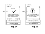
- a message 601 of unsuccessful installation ( figure 6-A ), or if necessary a failure message 602 ( figure 6-B ) is then sent from the remote data center 110 to the electronic device 106.
Abstract
-On an electronic device (106) determining the pointing information (401 ;402) to be applied to the outdoor unit (101);
- Receiving signal quality information (SQI) on said electronic device (106) and from an indoor unit (103), said indoor unit (103) comprising a modem or receiver and being connected to the outdoor unit (101);
- Pointing the outdoor unit (101) according to the received signal quality information (SQI).
Description
- The present invention relates to a method for the installation of an outdoor unit (O.D.U) , the installation being made with a single electronic device able to help the installer and to give appropriate information during different steps of the installation. The present invention also relates to the electronic device used during the installation. The invention also relates advantageously to reporting on the installation to a third party
- By "O.D.U", it should be understood all the elements that constitute what is commonly called a "satellite antenna"; these elements include a satellite dish (also called "antenna"), a Low Noise Converter - LNB, in some examples a transmitter - and various mechanical elements involved in pointing the satellite dish and the LNB.
- The O.D.U cooperates with an indoor unit (I.D.U)., which is either a Satellite TV receiver or a modem, placed inside a house. The receiver allows the reception of television signals and displays them on a screen. Most of the time, the O.D.U and the I.D.U. are linked by a physical wire. This physical wire allows the transmission of signals emitted by a satellite and received by the O.D.U from the O.D.U to the I.D.U., and in some systems, this physical wire allows also the transmission of signals from the I.D.U. to the O.D.U and to the satellite.
- Proper installation of a satellite dish remains a difficult operation for users. They often prefer to hire a professional installer. If a user wants to install his own O.D.U, he often has to climb a ladder to fix the O.D.U in a suitable location of his dwelling. Smartphone Apps or Tools are available to help to choose a correct installation position and even roughly direct the dish to receive the satellite signals. For example, the smartphone indicates the elevation angle and azimuth direction to apply to the dish. Once the dish has been directed according to the smartphone's indications, the user has then to enter his home to check whether the signals are correctly received and transmitted to the I.D.U..
In most cases, the user has to make a number of return journeys to refine the positioning of the dish until the dish is in the correct position and supplies good signal quality. These operations make the installation of the O.D.U long and laborious. The use of acoustic signals which are provided in some cases at the O.D.U are so far not sufficiently accurate and sometimes not able to identify the correct satellite. This often results in the user returning between the O.D.U and the I.D.U.. Satellite level meters inserted in the physical cable between the IDU and the ODU have the same disadvantages as the acoustic signal described above. - In addition, different operators clearly prefer the installation of O.D.U being performed by professional installer, so that the installation can be validated. If a malfunction occurs after proper installation of the antenna (such a malfunction can occur for different reasons, for example a fast growing vegetation which obscures the satellite signal from and the dish). If that installation has not been done by a professional installer, a remote technical assistance will lack information to help the user solve the problems on his own. O.D.U. The reporting element of advantageous embodiments of the invention allows system or network operators to have information relating to the original installation of the O.D.U and allows troubleshooting and monitoring actions to be performed.
- The invention aims to remedy all or some of the disadvantages of the above identified background. The invention essentially makes the installation of O.D.U easy for all users, no returns between the O.D.U and the I.D.U. being necessary. This invention aims to substitute the use of expensive analyzers when pointing an ODU usually used by professionals. Advantageously, the invention also proposes to easily make a reporting of the installation which can then be used by the operators to validate the installation
- A first aspect of the invention relates then to a method for the installation of an outdoor unit, said outdoor unit receiving signals from a satellite, characterized in that it comprises the different steps of:
- On said electronic device determining the pointing information to be applied to the outdoor unit;
- Receiving signal quality information on said electronic device and from an indoor unit, said indoor unit comprising a modem or receiver and being connected to the outdoor unit;
- Pointing the outdoor unit according to the received signal quality information.
- According to various embodiments, such a method of installation comprises one or more of the features below, which should be considered in any possible technical combinations:
- On the electronic device, determining the ideal installation position with a clear line of sight to the satellite
- On the electronic device, determining the IDU configuration information based on previously programmed information and GPS coordinates
- Once the I.D.U. is configured correctly for installation mode the I.D.U. will identify the correct satellite and pass this information to the electronic device.
- The method of installation comprises the step of configuring the I.D.U. in a correct installation mode.
- Once the I.D.U. is configured correctly for installation mode the I.D.U. identifies the correct satellite and passes this information to the electronic device.
- The signal quality information received by the electronic device is transmitted from the I.D.U. through a wireless link.
- The signal quality information received by the electronic device is transmitted from the I.D.U. through a wireless link established between the electronic device and a wireless device plugged onto the I.D.U.
- The pointing information to be applied to the outdoor unit is determined by the electronic device based on geographical position information obtained by a GPS module of the electronic device.
- The pointing information to be applied to the antenna is displayed by a graphical indication displayed on a screen of the electronic device, said graphical indication representing the antenna to be installed in the correct position.
- The method of installation comprises the prior step of checking, within the electronic device, the operation of a wireless link between said electronic device and the indoor unit, and the operation of a GPS module of said electronic device.
- The signal quality information is displayed on a screen of the electronic device as an instantaneous value of signal quality determined by the I.D.U., said signal being relevant for correctly positioning the O.D.U.
- The electronic device stores an optimum value of the signal quality during the step of the O.D.U positioning.
- The signal quality information is restored by the electronic device as a sound signal whose frequency and/or pulse and / or intensity varies with the signal quality information.
- The method of installation comprises a validation step of the outdoor unit installation including an operation consisting in comparing the signal quality information to a predetermined threshold value, the O.D.U installation being validated only if the threshold value is reached.
- The I.D.U. use is disabled until the O.D.U installation is validated.
- The comparison operation consists in comparing the signal quality to a minimum value, the installation of the O.D.U being validated only if the signal quality exceeds the minimum value.
- The method of installation comprises the further step of transmitting from the electronic device to a data processing center, a set of information detailing the O.D.U installation.
- The set of information dealing with the O.D.U installation is sent as secure electronic message. This message allows the verification of the semantic integrity.
- The set of information dealing with the O.D.U installation comprises at least one picture of the installed antenna, said picture having been taken with the electronic device.
- Another aspect of the invention relates then to an electronic device for the implementation of the method according to the invention, said electronic device being used for the installation of an O.D.U comprising an antenna and a LNB, said electronic device comprising:
- Means for determining pointing information to be applied to the outdoor unit based on geographical positioning information obtained by a GPS module of said electronic device
- Means for receiving signal quality information transmitted from an I.D.U. comprising a modem or a receiver connected to the O.D.U to be installed.
- The electronic device according to the invention is advantageously a smartphone or a tablet.
- Some embodiments of the present invention are now described, by way of example only, and with reference to the accompanying drawings, in which:
-
FIG. 1 is a schematic representation of different elements involved in the method according to the invention, and the exchanges between these elements. -
FIG. 2 is a first screenshot, corresponding to a step of the method according to the invention, of a screen of an electronic device used in the method according to the invention if there is no Wi Fi connection -
FIG. 3 is second screenshot, corresponding to a step of the method according to the invention, of the screen of the electronic device if there is no GPS information for the electronic device -
FIG. 4 is third screenshot, corresponding to a step of the method according to the invention, of the screen of the electronic device. This screen displays the pointing data for the ODU and a modem configuration -
FIG. 5 is fourth screenshot, corresponding to a step of the method according to the invention, of the screen of the electronic device. This screen shot displays the current and Peak SNR values (Signal to Noise Ratio) displayed during the pointing of the antenna. -
FIG. 6-A and Fig 6-B are respectively a fifth and a sixth screenshot, corresponding to a step of the method according to the invention, of the screen of the electronic device. These screenshots confirm the successful delivery or failure to deliver the installation report. - The same reference number represents the same element to the same type of element on all drawings, unless stated otherwise.
- The figures and the following description illustrate specific exemplary embodiments of the invention. It will thus be appreciated that those skilled in the art will be able to devise various arrangements that, although not explicitly described or shown herein, embody the principles of the invention and are included within the scope of the invention. Furthermore, any examples described herein are intended to aid in understanding the principles of the invention, and are to be construed as being without limitation to such specifically recited examples and conditions. As a result, the invention is not limited to the specific embodiments or examples described below, but by the claims and their equivalents.
- Referring to
figure 1 , it is depicted a schematic representation of different elements involved in the method according to the invention, and the exchanges between these elements. - On this picture, an O.D.U 101 has to be installed on a
house 102, typically on the wall of thehouse 102. The O.D.U 101 is linked to an I.D.U. 103 located inside the house and connected to aTV set 120 or a Personal Computer. The link between the O.D.U 101 and the I.D.U. 103 is awire 104 that allows an exchange of information between these two units. In the case of a "Tooway" system, the exchange of information is bidirectional. - A
user 105 wants to install the antenna on his dwelling. He is equipped with anelectronic device 106 which can be for example a smartphone, or a tablet, or any other electronic device comprising a screen and small enough to be easily brought up a ladder for example. A specific application APP is memorized in theelectronic device 106 in order to achieve the described example of the invention. - On the described example, the application proceeds with preliminary check operations: a first check consists in making sure that a wireless (wi-fi, blue tooth, or other...) connection exists between the
electronic device 106 and the I.D.U. 103, especially with the modem or receiver of the I.D.U. 103. If no connection is detected, an appropriate message 201 (figure 2 ) is displayed on the screen of theelectronic device 106. A second check consists in making sure that aGPS module 107 of theelectronic device 106 is working and can receive useful GPS information. If theGPS module 107 of theelectronic device 106 is not working, an error message 301 (figure 3 ) is displayed on the screen of theelectronic device 106. - Once the preliminary checks achieved, the
user 105 gets through theGPS module 107 of the electronic device 106 a pointing information. The pointing information is determined by theelectronic device 106 based on geographical position information obtained by theGPS module 107. The pointing information is displayed on the screen of the electronic device 106 (figure 4 ). The pointing information gives a value for anelevation 401 and a value for anazimuth 402 to apply to the antenna of the O.D.U 101. To help theuser 105 to correctly orientate the antenna, agraphical indication 403 is displayed on the screen of theelectronic device 106, saidgraphical indication 403 showing the antenna to be installed in the correct position. In some embodiments, as shown onfigure 4 , two different kinds of antenna are represented, the user having the possibility to determine which represented antenna corresponds to the antenna he has to install. Simultaneously, aninformation 404 dealing with the appropriate spot to use for a certain transmitting VSAT system is also displayed on the screen of theelectronic device 106. - In some embodiments, thanks to the specific application of the
electronic device 106, the electronic device will configure the I.D.U. 103 in a correct installation mode. The following steps will occur: - ascertaining on which spot the
electronic device 106 should program the I.D.U. 103; thisinformation 404 is given by theelectronic device 106; - sending a command from the
electronic device 106 to the I.D.U. 103 in order to activate an installation mode on the I.D.U. 103, - sending a command from the
electronic device 106 to the I.D.U. 103 in order to indicate to the modem or receiver which spot or coverage to choose, the spot defining the polarization and the frequency to look for during the installation of the O.D.U 101. - When the
user 105 starts to move the antenna, he then instantaneously receives on the electronic device 106 a signal quality information SQI. Onfigure 5 , this signal quality information is a signal quality giving acurrent SNR value 501 which is displayed on the screen of theelectronic device 106. In other embodiments, the signal quality information SQI is not a signal to noise ratio, but a value which can correspond for example to CBER, VBER, MER, C/N, Power, dBm and dBu. The reception signal quality information SQI is transmitted by the I.D.U. 103 to theelectronic device 106 by a wireless link 108; advantageously, the wireless link is established between theelectronic device 106 and awireless device 109 plugged onto the I.D.U. 103. Theuser 105 moves the antenna accordingly, pointing the O.D.U 101 according to the received signal quality information SQI. - Advantageously, the
electronic device 106 stores anoptimum value 502 of the signal quality during the O.D.U 101 pointing. Thus, if theuser 105 keeps on moving the antenna after having reached theoptimum value 502, he knows that he can get again this optimum 502 value by moving back the antenna. - Advantageously, the reception signal quality information SQI is restored by the
electronic device 106 as a sound signal whose frequency, pulse and / or intensity varies with the reception signal quality information. - In a preferred embodiment, when the user thinks that he has completed the installation of the O.D.U 101, he proceeds, through his
electronic device 106, to a validation step. To this end, some data is sent from theelectronic device 106 using the specific application to aremote data center 110. - More specifically, the following data can be transmitted from the electronic device to the remote data center:
- the current value of the signal quality once the O.D.U 101 is no longer moved by the
user 105; - some pictures PIC of the installation taken by a
camera 111 of theelectronic device 106; these pictures will notably allow theremote data center 110 to determine the reasons of a possible future failure. - The GPS location of the installation location.
- The specific application APP can use a message, for example an e-mail to send through a cellular network this data to a
remote data center 110. The data, and especially the current value of the signal quality will be compared to a predetermined threshold value, the O.D.U 101 installation being validated only if the threshold value is reached. In another embodiment, this comparison is computed in theelectronic device 106 itself. - In some embodiments, the I.D.U. 103 use is disabled until the O.D.U 101 installation is validated.The message is secured and has a unique semantic integrity which is associated with the particular installation.
- A
message 601 of unsuccessful installation (figure 6-A ), or if necessary a failure message 602 (figure 6-B ) is then sent from theremote data center 110 to theelectronic device 106.
Claims (15)
- A method for the installation of an outdoor unit (101) , said outdoor unit (101) receiving signals from a satellite, characterized in that it comprises the different steps of:- On an electronic device (106) determining the pointing information (401 ;402) to be applied to the outdoor unit (101);- Receiving signal quality information (SQI) on said electronic device (106) and from an indoor unit (103), said indoor unit (103) comprising a modem or receiver and being connected to the outdoor unit (101);- Pointing the outdoor unit (101) according to the received signal quality information (SQI).
- The method according to claim 1 characterized in that it comprises the step of configuring the indoor unit (103) in a correct installation mode.
- The method according to any of the claims 1 or 2 characterized in that the signal quality information (SQI) received by the electronic device (106) is transmitted from the indoor unit (103) through a wireless link.
- The method according to any of the claims 1 to 3 characterized in that the pointing information (401 ;402) to be applied to the outdoor unit (101) is determined by the electronic device (106) based on geographical position information obtained by a GPS module (107) of the electronic device (106).
- The method according to claim 4 characterized in that the pointing information (401 ;402) to be applied to the antenna is displayed by a graphical indication on a screen of the electronic device (106), said graphical indication representing a generic or specific antenna to be installed in the correct position.
- The method according to any of the claims 1 to 5 characterized in that it comprises the prior step of checking, within the electronic device (106), the operation of a wireless link between said electronic device (106) and the indoor unit (103), and the operation of a GPS module (107) of said electronic device (106).
- The method according to any of the claims 1 to 6 characterized in that the signal quality information (RSI) is displayed on a screen of the electronic device (106) as an instantaneous value of a signal quality determined by the indoor unit (103), said signal being relevant for correctly positioning the outdoor unit (101).
- The method according to any of the claims 1 to 7 characterized in that the reception signal quality information (SQI) is restored by the electronic device (106) as a sound signal whose frequency and/or pulse and / or intensity varies with the reception signal quality information (SQI).
- The method of any of the claims 1 to 8 characterized in that it comprises a validation step of the outdoor unit (101) installation including an operation consisting in comparing the signal quality information (SQI) to a predetermined threshold value, the outdoor unit (101) installation being validated only if the threshold value is reached.
- The method according to claim 9 and according to claim 7 characterized in that the comparison operation consists in comparing the signal quality to a minimum value, the installation of the outdoor unit (101) being validated only if the signal quality exceeds the minimum value.
- The method according to any of the claims 1 to 10 characterized in that it comprises the further step of transmitting from the electronic device (106) to a data processing center (110), a set of information detailing the outdoor unit (101) installation
- The method according to claim 11 characterized in that the set of information dealing with the outdoor unit (101) installation is sent as a secure electronic message
- The method according to any of the claims 14 or 15 characterized in that the set of information dealing with the outdoor unit (101) installation comprises at least one picture (PIC) of the installed outdoor unit (101), said picture (PIC) having been taken with the electronic device (106).
- The method according to claim 13 characterized in that the electronic device (106) is a smartphone or a tablet.
- Electronic device (106) for the implementation of the method according to any the claim 1 to 14, said electronic device (106) being used for the installation of an outdoor unit (101) comprising an antenna and a LNB said electronic device (106) comprising:- Means for determining pointing information (401; 402) to be applied to the outdoor unit based on geographical pointing information obtained by a GPS module (107) of said electronic device 106);- Means for receiving reception signal quality information (SQI) transmitted from an indoor unit (103) comprising a modem or a receiver connected to the outdoor unit (101) to be installed.
Priority Applications (7)
| Application Number | Priority Date | Filing Date | Title |
|---|---|---|---|
| EP14172444.3A EP2955783A1 (en) | 2014-06-13 | 2014-06-13 | A method for the installation with an electronic device of an outdoor unit and electronic device for such an installation |
| MA38172A MA38172B1 (en) | 2014-06-13 | 2015-06-09 | Method for installing an outdoor unit |
| MX2015007455A MX347043B (en) | 2014-06-13 | 2015-06-11 | Method for the installation with an electronic device of an outdoor unit and electronic device for such an installation. |
| BR102015013769A BR102015013769A2 (en) | 2014-06-13 | 2015-06-11 | method for installation with an electronic device of an external unit and electronic device for said installation |
| IL239356A IL239356A0 (en) | 2014-06-13 | 2015-06-11 | A method for the installation with an electronic device of an outdoor unit and electronic device for such an installation |
| RU2015122517A RU2690100C2 (en) | 2014-06-13 | 2015-06-12 | Method of installing an outdoor unit using an electronic device and an electronic device for such an installation |
| US14/737,775 US10237128B2 (en) | 2014-06-13 | 2015-06-12 | Method for the installation with an electronic device of an outdoor unit and electronic device for such an installation |
Applications Claiming Priority (1)
| Application Number | Priority Date | Filing Date | Title |
|---|---|---|---|
| EP14172444.3A EP2955783A1 (en) | 2014-06-13 | 2014-06-13 | A method for the installation with an electronic device of an outdoor unit and electronic device for such an installation |
Publications (1)
| Publication Number | Publication Date |
|---|---|
| EP2955783A1 true EP2955783A1 (en) | 2015-12-16 |
Family
ID=50979547
Family Applications (1)
| Application Number | Title | Priority Date | Filing Date |
|---|---|---|---|
| EP14172444.3A Withdrawn EP2955783A1 (en) | 2014-06-13 | 2014-06-13 | A method for the installation with an electronic device of an outdoor unit and electronic device for such an installation |
Country Status (7)
| Country | Link |
|---|---|
| US (1) | US10237128B2 (en) |
| EP (1) | EP2955783A1 (en) |
| BR (1) | BR102015013769A2 (en) |
| IL (1) | IL239356A0 (en) |
| MA (1) | MA38172B1 (en) |
| MX (1) | MX347043B (en) |
| RU (1) | RU2690100C2 (en) |
Families Citing this family (3)
| Publication number | Priority date | Publication date | Assignee | Title |
|---|---|---|---|---|
| US10171188B2 (en) * | 2014-12-02 | 2019-01-01 | Hewlett-Packard Development Company, L.P. | Mobile computing device including a graphical indicator |
| CA3001924A1 (en) * | 2015-10-22 | 2017-04-27 | Thales Alenia Space Italia S.P.A. Con Unico Socio | Method and systems for increasing capacity and safety of aeronautical safety-of-life services and data links |
| US20210011702A1 (en) * | 2019-07-12 | 2021-01-14 | Dish Network L.L.C. | Systems and methods for updating television receiving devices |
Citations (3)
| Publication number | Priority date | Publication date | Assignee | Title |
|---|---|---|---|---|
| US6216266B1 (en) * | 1999-10-28 | 2001-04-10 | Hughes Electronics Corporation | Remote control signal level meter |
| US20020032028A1 (en) * | 2000-07-06 | 2002-03-14 | Arthur Kaupe | Method and apparatus for automatic collection and loading of configuration data into equipment by installers using wireless technology |
| US20060235611A1 (en) * | 2005-04-18 | 2006-10-19 | Dataforensics, Llc | Systems and methods for recording and reporting data collected from a remote location |
Family Cites Families (11)
| Publication number | Priority date | Publication date | Assignee | Title |
|---|---|---|---|---|
| US6509934B1 (en) * | 1998-12-22 | 2003-01-21 | Mitsubishi Electric Research Laboratories, Inc. | Directing an antenna to receive digital television signals |
| JP2005077138A (en) * | 2003-08-28 | 2005-03-24 | Fujitsu Ltd | Position measuring system |
| US7634598B2 (en) * | 2005-08-17 | 2009-12-15 | Permanent Solution Industries, Inc. | Dynamic total asset management system (TAMS) and method for managing building facility services |
| KR100798129B1 (en) * | 2006-09-06 | 2008-02-01 | 위월드 주식회사 | Satellite antenna system of tracking mode-selective type |
| ITMI20071333A1 (en) * | 2007-07-05 | 2009-01-06 | Ro Ve R Lab S P A | IMPROVED DEVICE FOR VERIFICATION AND CALIBRATION OF THE TV SIGNAL |
| US8789116B2 (en) * | 2011-11-18 | 2014-07-22 | Electronic Controlled Systems, Inc. | Satellite television antenna system |
| US20150120388A1 (en) * | 2012-03-29 | 2015-04-30 | Changi Airport Group (Singapore) Pte. Ltd. | Work and quality management system, device and method |
| US9660321B2 (en) * | 2012-04-12 | 2017-05-23 | Maxlinear, Inc. | Method and system for a mobile application (app) that assists with aiming or aligning a satellite dish or antenna |
| US20130271319A1 (en) * | 2012-04-12 | 2013-10-17 | Alan Trerise | Method and system for aiming and aligning self-installed broadcast signal receivers |
| US20150106144A1 (en) * | 2013-10-13 | 2015-04-16 | Wavsys Llc | Field crew management system and method |
| GB2524723A (en) * | 2014-03-11 | 2015-10-07 | Avanti Broadband Ltd | Method, apparatus and system for use in satellite broadband installation |
-
2014
- 2014-06-13 EP EP14172444.3A patent/EP2955783A1/en not_active Withdrawn
-
2015
- 2015-06-09 MA MA38172A patent/MA38172B1/en unknown
- 2015-06-11 MX MX2015007455A patent/MX347043B/en active IP Right Grant
- 2015-06-11 IL IL239356A patent/IL239356A0/en unknown
- 2015-06-11 BR BR102015013769A patent/BR102015013769A2/en not_active Application Discontinuation
- 2015-06-12 US US14/737,775 patent/US10237128B2/en not_active Expired - Fee Related
- 2015-06-12 RU RU2015122517A patent/RU2690100C2/en not_active IP Right Cessation
Patent Citations (3)
| Publication number | Priority date | Publication date | Assignee | Title |
|---|---|---|---|---|
| US6216266B1 (en) * | 1999-10-28 | 2001-04-10 | Hughes Electronics Corporation | Remote control signal level meter |
| US20020032028A1 (en) * | 2000-07-06 | 2002-03-14 | Arthur Kaupe | Method and apparatus for automatic collection and loading of configuration data into equipment by installers using wireless technology |
| US20060235611A1 (en) * | 2005-04-18 | 2006-10-19 | Dataforensics, Llc | Systems and methods for recording and reporting data collected from a remote location |
Also Published As
| Publication number | Publication date |
|---|---|
| MA38172B1 (en) | 2016-10-31 |
| IL239356A0 (en) | 2015-11-30 |
| MX347043B (en) | 2017-04-10 |
| BR102015013769A2 (en) | 2016-08-02 |
| RU2690100C2 (en) | 2019-05-30 |
| US20150365280A1 (en) | 2015-12-17 |
| MA38172A1 (en) | 2016-03-31 |
| US10237128B2 (en) | 2019-03-19 |
| RU2015122517A3 (en) | 2018-12-17 |
| MX2015007455A (en) | 2015-12-14 |
| RU2015122517A (en) | 2017-01-10 |
Similar Documents
| Publication | Publication Date | Title |
|---|---|---|
| US11595223B2 (en) | Automated methods and apparatus for facilitating the design and deployment of monitoring systems | |
| JP5872594B2 (en) | Satellite communication system and antenna adjustment method | |
| JP6211588B2 (en) | United positioning method and apparatus | |
| EP2955783A1 (en) | A method for the installation with an electronic device of an outdoor unit and electronic device for such an installation | |
| US9008588B2 (en) | System and method for the calibration and verification of wireless networks with control network | |
| JP2009302926A (en) | Radio access point apparatus and access point management apparatus | |
| TWI675215B (en) | Indoor positioning system | |
| KR20180130761A (en) | System, server and method for determining location inforamtion | |
| US9350467B2 (en) | Terminal diagnosis self correction method and system | |
| JP6770451B2 (en) | Communication systems, communication devices and servers | |
| JP6602526B2 (en) | Location information acquisition system | |
| WO2016047091A1 (en) | Wireless communication system, access point, control device, and location calculation method | |
| JP2017163381A (en) | Information output server, information output method, and information output program | |
| KR101566308B1 (en) | System for monitoring and controlling the state of low power rf repeater and method therefor | |
| US10841813B2 (en) | Device to guide equipment cable installation between radio ports of a base station and multiple antennas | |
| JPWO2019123599A1 (en) | Positioning system, positioning method and receiver | |
| US20170016992A1 (en) | Satellite modem location tracking | |
| JP4853489B2 (en) | Automatic wireless meter reading system and program thereof | |
| EP2667356A2 (en) | Information distribution apparatus, information distribution system and information distribution method | |
| EP3352391A1 (en) | Method and system for determining parameters of an audio/video signal | |
| JP4839679B2 (en) | Automatic wireless meter reading system and program thereof | |
| JP2015032983A (en) | Installation checker and interphone apparatus for collective housing | |
| JP2021056910A (en) | Site data management system of disaster prevention monitoring facility | |
| KR20190061255A (en) | Femto cell positioning method and femto cell positioning system | |
| JP2007078575A (en) | Positional information transmitting device and positional information display system |
Legal Events
| Date | Code | Title | Description |
|---|---|---|---|
| PUAI | Public reference made under article 153(3) epc to a published international application that has entered the european phase |
Free format text: ORIGINAL CODE: 0009012 |
|
| AK | Designated contracting states |
Kind code of ref document: A1 Designated state(s): AL AT BE BG CH CY CZ DE DK EE ES FI FR GB GR HR HU IE IS IT LI LT LU LV MC MK MT NL NO PL PT RO RS SE SI SK SM TR |
|
| AX | Request for extension of the european patent |
Extension state: BA ME |
|
| 17P | Request for examination filed |
Effective date: 20160616 |
|
| RBV | Designated contracting states (corrected) |
Designated state(s): AL AT BE BG CH CY CZ DE DK EE ES FI FR GB GR HR HU IE IS IT LI LT LU LV MC MK MT NL NO PL PT RO RS SE SI SK SM TR |
|
| STAA | Information on the status of an ep patent application or granted ep patent |
Free format text: STATUS: EXAMINATION IS IN PROGRESS |
|
| 17Q | First examination report despatched |
Effective date: 20190423 |
|
| STAA | Information on the status of an ep patent application or granted ep patent |
Free format text: STATUS: EXAMINATION IS IN PROGRESS |
|
| STAA | Information on the status of an ep patent application or granted ep patent |
Free format text: STATUS: THE APPLICATION IS DEEMED TO BE WITHDRAWN |
|
| 18D | Application deemed to be withdrawn |
Effective date: 20210112 |