EP2955519A1 - Lateral flow membrane for multiparameter readouts and immunoassay device comprising the same - Google Patents
Lateral flow membrane for multiparameter readouts and immunoassay device comprising the same Download PDFInfo
- Publication number
- EP2955519A1 EP2955519A1 EP14290166.9A EP14290166A EP2955519A1 EP 2955519 A1 EP2955519 A1 EP 2955519A1 EP 14290166 A EP14290166 A EP 14290166A EP 2955519 A1 EP2955519 A1 EP 2955519A1
- Authority
- EP
- European Patent Office
- Prior art keywords
- lateral flow
- membrane
- lanes
- multiparameter
- flow
- Prior art date
- Legal status (The legal status is an assumption and is not a legal conclusion. Google has not performed a legal analysis and makes no representation as to the accuracy of the status listed.)
- Granted
Links
Images


Classifications
-
- B—PERFORMING OPERATIONS; TRANSPORTING
- B01—PHYSICAL OR CHEMICAL PROCESSES OR APPARATUS IN GENERAL
- B01L—CHEMICAL OR PHYSICAL LABORATORY APPARATUS FOR GENERAL USE
- B01L3/00—Containers or dishes for laboratory use, e.g. laboratory glassware; Droppers
- B01L3/50—Containers for the purpose of retaining a material to be analysed, e.g. test tubes
- B01L3/502—Containers for the purpose of retaining a material to be analysed, e.g. test tubes with fluid transport, e.g. in multi-compartment structures
- B01L3/5023—Containers for the purpose of retaining a material to be analysed, e.g. test tubes with fluid transport, e.g. in multi-compartment structures with a sample being transported to, and subsequently stored in an absorbent for analysis
-
- G—PHYSICS
- G01—MEASURING; TESTING
- G01N—INVESTIGATING OR ANALYSING MATERIALS BY DETERMINING THEIR CHEMICAL OR PHYSICAL PROPERTIES
- G01N33/00—Investigating or analysing materials by specific methods not covered by groups G01N1/00 - G01N31/00
- G01N33/48—Biological material, e.g. blood, urine; Haemocytometers
- G01N33/50—Chemical analysis of biological material, e.g. blood, urine; Testing involving biospecific ligand binding methods; Immunological testing
- G01N33/53—Immunoassay; Biospecific binding assay; Materials therefor
- G01N33/543—Immunoassay; Biospecific binding assay; Materials therefor with an insoluble carrier for immobilising immunochemicals
- G01N33/54366—Apparatus specially adapted for solid-phase testing
- G01N33/54386—Analytical elements
- G01N33/54387—Immunochromatographic test strips
- G01N33/54388—Immunochromatographic test strips based on lateral flow
-
- B—PERFORMING OPERATIONS; TRANSPORTING
- B01—PHYSICAL OR CHEMICAL PROCESSES OR APPARATUS IN GENERAL
- B01L—CHEMICAL OR PHYSICAL LABORATORY APPARATUS FOR GENERAL USE
- B01L3/00—Containers or dishes for laboratory use, e.g. laboratory glassware; Droppers
- B01L3/50—Containers for the purpose of retaining a material to be analysed, e.g. test tubes
- B01L3/502—Containers for the purpose of retaining a material to be analysed, e.g. test tubes with fluid transport, e.g. in multi-compartment structures
- B01L3/5027—Containers for the purpose of retaining a material to be analysed, e.g. test tubes with fluid transport, e.g. in multi-compartment structures by integrated microfluidic structures, i.e. dimensions of channels and chambers are such that surface tension forces are important, e.g. lab-on-a-chip
- B01L3/502707—Containers for the purpose of retaining a material to be analysed, e.g. test tubes with fluid transport, e.g. in multi-compartment structures by integrated microfluidic structures, i.e. dimensions of channels and chambers are such that surface tension forces are important, e.g. lab-on-a-chip characterised by the manufacture of the container or its components
-
- G—PHYSICS
- G01—MEASURING; TESTING
- G01N—INVESTIGATING OR ANALYSING MATERIALS BY DETERMINING THEIR CHEMICAL OR PHYSICAL PROPERTIES
- G01N21/00—Investigating or analysing materials by the use of optical means, i.e. using sub-millimetre waves, infrared, visible or ultraviolet light
- G01N21/84—Systems specially adapted for particular applications
- G01N21/8483—Investigating reagent band
-
- G—PHYSICS
- G01—MEASURING; TESTING
- G01N—INVESTIGATING OR ANALYSING MATERIALS BY DETERMINING THEIR CHEMICAL OR PHYSICAL PROPERTIES
- G01N33/00—Investigating or analysing materials by specific methods not covered by groups G01N1/00 - G01N31/00
- G01N33/48—Biological material, e.g. blood, urine; Haemocytometers
- G01N33/50—Chemical analysis of biological material, e.g. blood, urine; Testing involving biospecific ligand binding methods; Immunological testing
- G01N33/53—Immunoassay; Biospecific binding assay; Materials therefor
- G01N33/536—Immunoassay; Biospecific binding assay; Materials therefor with immune complex formed in liquid phase
- G01N33/537—Immunoassay; Biospecific binding assay; Materials therefor with immune complex formed in liquid phase with separation of immune complex from unbound antigen or antibody
- G01N33/538—Immunoassay; Biospecific binding assay; Materials therefor with immune complex formed in liquid phase with separation of immune complex from unbound antigen or antibody by sorbent column, particles or resin strip, i.e. sorbent materials
-
- G—PHYSICS
- G01—MEASURING; TESTING
- G01N—INVESTIGATING OR ANALYSING MATERIALS BY DETERMINING THEIR CHEMICAL OR PHYSICAL PROPERTIES
- G01N33/00—Investigating or analysing materials by specific methods not covered by groups G01N1/00 - G01N31/00
- G01N33/48—Biological material, e.g. blood, urine; Haemocytometers
- G01N33/50—Chemical analysis of biological material, e.g. blood, urine; Testing involving biospecific ligand binding methods; Immunological testing
- G01N33/53—Immunoassay; Biospecific binding assay; Materials therefor
- G01N33/558—Immunoassay; Biospecific binding assay; Materials therefor using diffusion or migration of antigen or antibody
-
- G—PHYSICS
- G01—MEASURING; TESTING
- G01N—INVESTIGATING OR ANALYSING MATERIALS BY DETERMINING THEIR CHEMICAL OR PHYSICAL PROPERTIES
- G01N33/00—Investigating or analysing materials by specific methods not covered by groups G01N1/00 - G01N31/00
- G01N33/48—Biological material, e.g. blood, urine; Haemocytometers
- G01N33/50—Chemical analysis of biological material, e.g. blood, urine; Testing involving biospecific ligand binding methods; Immunological testing
- G01N33/74—Chemical analysis of biological material, e.g. blood, urine; Testing involving biospecific ligand binding methods; Immunological testing involving hormones or other non-cytokine intercellular protein regulatory factors such as growth factors, including receptors to hormones and growth factors
- G01N33/76—Human chorionic gonadotropin including luteinising hormone, follicle stimulating hormone, thyroid stimulating hormone or their receptors
-
- B—PERFORMING OPERATIONS; TRANSPORTING
- B01—PHYSICAL OR CHEMICAL PROCESSES OR APPARATUS IN GENERAL
- B01L—CHEMICAL OR PHYSICAL LABORATORY APPARATUS FOR GENERAL USE
- B01L2200/00—Solutions for specific problems relating to chemical or physical laboratory apparatus
- B01L2200/10—Integrating sample preparation and analysis in single entity, e.g. lab-on-a-chip concept
-
- B—PERFORMING OPERATIONS; TRANSPORTING
- B01—PHYSICAL OR CHEMICAL PROCESSES OR APPARATUS IN GENERAL
- B01L—CHEMICAL OR PHYSICAL LABORATORY APPARATUS FOR GENERAL USE
- B01L2300/00—Additional constructional details
- B01L2300/06—Auxiliary integrated devices, integrated components
- B01L2300/069—Absorbents; Gels to retain a fluid
-
- B—PERFORMING OPERATIONS; TRANSPORTING
- B01—PHYSICAL OR CHEMICAL PROCESSES OR APPARATUS IN GENERAL
- B01L—CHEMICAL OR PHYSICAL LABORATORY APPARATUS FOR GENERAL USE
- B01L2300/00—Additional constructional details
- B01L2300/08—Geometry, shape and general structure
- B01L2300/0809—Geometry, shape and general structure rectangular shaped
- B01L2300/0825—Test strips
-
- B—PERFORMING OPERATIONS; TRANSPORTING
- B01—PHYSICAL OR CHEMICAL PROCESSES OR APPARATUS IN GENERAL
- B01L—CHEMICAL OR PHYSICAL LABORATORY APPARATUS FOR GENERAL USE
- B01L2300/00—Additional constructional details
- B01L2300/08—Geometry, shape and general structure
- B01L2300/0861—Configuration of multiple channels and/or chambers in a single devices
- B01L2300/0883—Serpentine channels
-
- B—PERFORMING OPERATIONS; TRANSPORTING
- B01—PHYSICAL OR CHEMICAL PROCESSES OR APPARATUS IN GENERAL
- B01L—CHEMICAL OR PHYSICAL LABORATORY APPARATUS FOR GENERAL USE
- B01L2300/00—Additional constructional details
- B01L2300/12—Specific details about materials
-
- B—PERFORMING OPERATIONS; TRANSPORTING
- B01—PHYSICAL OR CHEMICAL PROCESSES OR APPARATUS IN GENERAL
- B01L—CHEMICAL OR PHYSICAL LABORATORY APPARATUS FOR GENERAL USE
- B01L2400/00—Moving or stopping fluids
- B01L2400/04—Moving fluids with specific forces or mechanical means
- B01L2400/0403—Moving fluids with specific forces or mechanical means specific forces
- B01L2400/0406—Moving fluids with specific forces or mechanical means specific forces capillary forces
-
- G—PHYSICS
- G01—MEASURING; TESTING
- G01N—INVESTIGATING OR ANALYSING MATERIALS BY DETERMINING THEIR CHEMICAL OR PHYSICAL PROPERTIES
- G01N2333/00—Assays involving biological materials from specific organisms or of a specific nature
- G01N2333/435—Assays involving biological materials from specific organisms or of a specific nature from animals; from humans
- G01N2333/575—Hormones
- G01N2333/59—Follicle-stimulating hormone [FSH]; Chorionic gonadotropins, e.g. HCG; Luteinising hormone [LH]; Thyroid-stimulating hormone [TSH]
Definitions
- the present invention relates to a multiparameter lateral flow membrane comprising separated isomorphic flow lanes, and to a multiparameter lateral flow immunoassay device comprising the same.
- immunoassays are routinely used to detect the presence or concentration of various substances, often referred to as ligands or analytes, in biological fluids such as blood, urine or saliva but also in a variety of other samples for example food extracts, surface water and else.
- a binding agent typically an antibody which is specific for the ligand to be detected
- a test fluid that may comprise the ligand to be detected is contacted with the solid support and a complex between the binding agent and the ligand is formed in case the ligand is present.
- labeled antibodies may be used that bind to the complex followed by visual detection of the labeled antibody bound to the complex.
- an immunoassay is put together with a readout following a competitive reaction.
- the analyte per se is immobilized on a solid support and competes for the binding of the conjugated antibody with the analyte present in the sample.
- a sample rich in the defined analyte leads to a low absolute signal at the test line.
- Porous materials such as nitrocellulose, nylon, cellulose acetate, glass fibers and other porous polymers have been employed as solid supports in solid phase immunoassays.
- a fluid to be tested for the presence of a ligand is applied to one end of a porous membrane layer and flows in lateral direction through the membrane under the action of capillary forces.
- the porous membrane comprises an immobilized binding agent that is capable of binding the ligand or the antibody against the ligand to be detected.
- the immobilized binding agent may be evenly distributed over the entire membrane.
- the immobilized binding agent is located in defined test or detection zones in the membrane, usually in narrow test lines that have been applied by means of contact or inkjet printing or other dispensing techniques.
- a thin layer of microporous material with immobilized binding agent is supported on a liquid-impermeable layer to provide sufficient rigidity to the fragile microporous material layer.
- a layer of microporous material with a thickness in the range of from about 80 to 200 ⁇ m is supported on a liquid-impermeable support layer, usually referred to as "membrane backing".
- a lateral flow immunoassay device typically in the form of a test strip, includes, in the direction of lateral flow, a prefilter pad, a conjugate pad, a lateral flow membrane as described above, and an adsorbent pad.
- a liquid sample containing the ligands or analytes, which presence or concentration needs to be assessed is dropped at one end of the lateral flow immunoassay device on the prefilter pad. The liquid sample will then migrate through capillary forces sequentially through the conjugate pad, the lateral flow membrane and finally into the adsorbent pad.
- the ligands or analytes will react with conjugate particles present in the conjugate pad and then with a capture molecule, usually an antibody, which has been previously dispensed onto the membrane as a test or detection zone, typically in the form of a line oriented orthogonal to the direction of lateral flow.
- a capture molecule usually an antibody
- the first lateral flow test strips capable to carry out a test with regard to one ligand or analyte have been developed in the 1980's. Since then, no major changes of said test format have been carried out, since it is rather cheap and compatible with mass production.
- lateral flow test strips or devices including more than one test line have been developed.
- said lateral flow test strips having multiple test lines are limited in the number of test lines (usually, only a maximum of 7 test lines is possible), since the moving speed of the liquid sample decreases at square of distance from the origin, the nature of the sample is frequently modified in an unpredictable manner when passing through multiple previous test lines, and the conjugate is depleted the longer the sample migrates through the test strip, such that a loss of sensitivity occurs.
- US 7,879,597 B2 discloses a system including test cells with a first sorbent material defining a first flow path for a solution, a second sorbent material defining a second flow path distinct from the first flow path for a sample, and a test site with immobilized antigens or antibodies or other ligand binding molecules located at the junction of the first and second sorbent materials for identifying one or more ligands.
- test formats have been developed.
- a major path of research consisted in reducing the volume of the test line in order to increase the number of conjugate particles per volume unit.
- test zones either lines or spots
- the other test zones need to be placed further apart, such that there is sufficient time for the sample flow to be again homogenized.
- the object underlying the present invention is to provide a lateral flow membrane being capable of testing multiple ligands or analytes (parameters) in a liquid sample, and having an improved assay sensitivity and signal intensity, and to provide a corresponding manufacturing method.
- the present invention relates to a multiparameter lateral flow membrane, comprising a microporous membrane layer which may be supported or not on a liquid-impermeable support layerfor lateral flow of a liquid through the microporous membrane layer, wherein the microporous membrane layer has two or more isomorphic flow lanes in the direction of lateral flow, wherein said two or more isomorphic flow lanes are separated by hydrophobic separation channels, and wherein each of said two or more isomorphic flow lanes comprises a detection zone or spot including a binding agent.
- the lateral flow membrane configured for multiparameter readouts according to the present invention can advantageously be applied in a multiparameter lateral flow immunoassay device.
- the invention relates to the use of the above-described multiparameter lateral flow membrane in immunological-based tests.
- the invention relates to a method for the manufacture of a multiparameter lateral flow membrane as described above, comprising the steps of:
- the invention relates to a multiparameter lateral flow test with two or more isomorphic lanes with dedicated reaction zone and dedicated conjugate storing zone, upstream of the reaction zone.
- the multiparameter lateral flow membrane 1 according to the present invention as shown in Fig. 1 to 3 is an elongate arrangement of a microporous membrane layer 2 supported on a liquid-impermeable support layer 3.
- the multiparameter lateral flow membrane 1 is suitable for lateral flow of a liquid through the microporous membrane layer 2 under the action of capillary forces and is typically used in lateral flow immunoassays for detecting a ligand or analyte in a test fluid that flows laterally through the microporous membrane layer 2.
- the microporous membrane layer 2 has two or more isomorphic flow lanes 4 in the direction of lateral flow, as shown in Fig. 1 and 2 .
- the width of the flow lanes 4 is not specifically restricted, however, is usually in the range of from 1 mm to 4 mm, preferably in the range of from 2 mm to 3 mm.
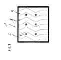
- the shape of the flow lanes 4 is not specifically restricted. However, preferably, the shape of the flow lanes 4 is selected from the group consisting of straight lanes, zig-zag-shaped lanes and meander-shaped lanes. More preferably, the shape of the flow lanes is selected from the group consisting of zig-zag-shaped lanes and meander-shaped lanes, as shown in Fig. 1 (zig-zag-shaped lanes) and Fig. 3 (meander-shaped lanes).
- the flow lanes 4 are separated by hydrophobic separation channels 5, as shown in Fig. 1 to 3 , and each of said two or more isomorphic flow lanes 4 comprises a detection zone 6 including one binding agent, as shown for e.g. in Fig. 1 , such that each detection zone 6 is supplied with the test liquid by its own flow lane.
- each of the several flow lanes 4 can comprise a detection zone and at least some of the several flow lanes can comprise identical or different binding agent(s). Due to said separation, each detection zone (reaction zone) will receive exactly the same amount and the same quality of sample and conjugate solution, which results in an improved assay sensitivity and signal intensity for each detection spot 6 ( Fig 5 ).
- each detection zone 6 has a diameter or dimension of from 0.5 mm to 3 mm, preferably of from 1 mm to 2 mm. Furthermore, the detection zone 6 preferably has a circular shape, but could also be in the shape of small lines (jetted non-contact spotting equipment). According to a preferred embodiment of the present invention, the hydrophobic separation channels 5 have a width of from 0.1 mm to 1 mm, preferably of from 0.15 mm to 1 mm.
- the microporous membrane layer 2 may be made of any suitable microporous material for lateral flow membranes. Such materials are known in the art and include nitrocellulose, nylon, cellulose acetate, PES (polyethersulfone), PVDF (polyvinylidenfluoride), cross-linked dextran and other porous polymers. Preferably, the microporous membrane layer 2 is a nitrocellulose layer. Nitrocellulose membrane layers for lateral flow assays are well-known in the art and are composed of interconnected nitrocellulose rods-in-a-sponge like structure.
- Liquid-impermeable support layers 3 are well-known in the art and are often referred to as "backing". Suitable support layers include polymeric materials such as for example polyester, polypropylene, polyethylene, acrylic (co)polymers, vinyl-acrylic polymers, polycarbonates and hetero-polysaccharides.
- each of said two or more isomorphic flow lanes 4 further comprises a control zone (as shown in Fig 5 ) including a binding agent downstream of the detection zone 6.
- Control zone of individual lanes can comprise different reagents. This control zone usually will bind all conjugate reagent or particle in excess.
- control zone The major role of the control zone is to assure that the liquid has been transported into the designated lane.
- the selected reagent combination will necessarily lead to a positive readout, independent of the outcome at the test zone.
- Figure 5 for example, an anti-mouse immunoglobulin purified from rabbit was printed at a final concentration of 1 mg/ml.
- each control zone has a diameter or dimension in the same range as the test zone, i.e. from 0.5 mm to 3 mm, preferably of from 0.2 mm to 1.0 mm.
- detectable markers such as for example immunolabels are typically used.
- the liquid to be analyzed first flows through a so-called conjugate pad before it flows through the lateral flow membrane.
- the conjugate pad comprises a moveable conjugate of detectable marker and a detection agent, i.e. an agent that can bind to the ligand or analyte but different from the binding agent. If the liquid to be analyzed flows through the conjugate pad, the conjugate binds to the ligand and the ligand/conjugate complex flows with the liquid through the membrane layer. In the membrane layer the ligand-conjugate complex binds to the immobilized binding agent.
- the moveable conjugate is usually specific to one analyte. Consequently in a multiparameter test several conjugate reagents are mixed and applied on the conjugated pad through the whole pad width. Another option would be to spray the individual conjugated reagents at regular interval on the conjugated pad. The width of the interval corresponds to the width of the flow lanes resulting in a higher concentration of the desired conjugate in a specified lane. This option may also reduce the amount of conjugate necessary to generate a visible signal because of the higher reagent concentration for the defined areal.
- the lateral flow membrane per se may comprise at least one conjugate zone that comprises a moveable conjugate of detectable marker and detection agent.
- Such conjugate zones are located upstream of a detection spot. In this case only the conjugate specific to the ligand on the detection zone will flow in the dedicated lane without any loss in the other lanes.
- Suitable detectable markers that can be used in this respect are not particularly limited and are known in the art. They include for example latex beads of different colors or fluorescent dyes as well as gold nanoparticles.
- each of said two or more isomorphic flow lanes 4 further comprises at least one conjugate spot that comprises a moveable conjugate of detectable marker and detection agent upstream of the detection spot 6.
- the membrane area used to deposit the conjugated reagent(s) can be slightly larger (0.5 mm) than the here defined isomorphic flow lane.
- the binding agents are selected from the group consisting of proteins and peptides in particular antibodies and aptamers.
- the present invention further relates to a lateral flow immunoassay device comprising the multiparameter lateral flow membrane according to the invention.
- Lateral flow immunoassay devices are well-known in the art and are for example described in US2006/0205059 , US 5,252,496 and US 5,591,645 .
- the multiparameter configured lateral flow membrane 1 according to the present invention may be used in any suitable lateral flow immunoassay device known in the art including in direct or competitive format.
- the multiparameter lateral flow immunoassay device comprise a reaction zone comprising the multiparameter configured lateral flow membrane 1 according to the present invention, a sample addition zone upstream of the reaction zone and an absorbing zone downstream of the reaction zone.
- Test fluid is added to the sample addition zone that typically comprises a filter pad in which the liquid is absorbed.
- the device may comprise a so-called conjugate zone comprising moveable immunolabels or other markers that are conjugated to a detection agent that binds to the ligand of interest in the test liquid, between the sample addition zone and the reaction zone, so that test liquid is forced to flow through the conjugate zone.
- the multiparameter configured lateral flow membrane 1 comprises at least one conjugate zone as described hereinabove.
- the method for the manufacture of the multiparameter lateral flow membrane 1 comprises the steps of
- the lateral flow membrane provided in step (a) of the present method is a common lateral flow membrane, which can be manufactured in a known manner, typically by first providing a liquid-impermeable support layer 3 and then applying a solution of the material of which the microporous membrane layer 2 is composed in a suitable solvent on the support layer 3. The solvent is then evaporated and a lateral flow membrane of a microporous membrane layer 2 supported on the liquid-impermeable support layer 3 is obtained.
- step (b) of the present method laser-etching of the microporous membrane layer 2 to form hydrophobic separation channels 5 is carried out, such that two or more isomorphic flow lanes 4 are provided in the direction of lateral flow.
- the microporous membrane layer 2 is treated with laser-etching such that the material of the microporous membrane layer 2 is removed from the liquid-impermeable support layer 3 and a plurality of isomorphic flow lanes 4 is formed, which are separated by hydrophobic borderlines 5 reaching down to the exposed hydrophobic material of the liquid-impermeable support layer 3.
- the laser etching process can be achieved for example by the use of a Nd:YVO 4 solid-state laser having picosecond pulses, especially at a wavelength of 532 nm and a pulse length of 12 psec, a pulse energy of 10 mJ and a pulse frequency of 10 kH.
- Alternative laser etching process with Nd YAG or CO 2 laser have also led to successful structuring of nitrocellulose membrane.
- the product from step (b) can be processed into different formats.
- a preferred embodiment is a roll.
- Another preferred embodiments of such a format is a package of sheets.
- a detection spot 6 including binding agent(s) is applied on each of said two or more isomorphic flow lanes 4 with common techniques.
- the detection spots 6 are applied by contact or inkjet printing or aerosol spraying.
- a conjugate zone that comprises a moveable conjugate of detectable marker and detection agent is applied upstream of the detection spots 6.
- Example 1 Preparation of a lateral flow membrane using an evaporation process
- a nitrocellulose-based lateral flow membrane is manufactured by an established evaporation process. Briefly, a polymer blend solution of nitrocellulose (3 to 10 % (wt)) with 30 to 50 % (wt) of alcohol, 40 to 60 % (wt) of methyl acetate, and 7 to 13 % (wt) of water is applied on a stainless belt or on a polyester film. The casting line offers a controlled evaporation process of the volatile components. The resulting membrane is impregnated with an anionic surfactant to assure homogeneous capillary flow through the whole membrane thickness. The membrane is then dried, winded into final rolls and carefully examined for physical and chemical characteristics.
- the ready to use lateral flow membrane is laminated onto backing card (G&L Precision Die Cutting) and structured by laser etching to allow for multiple individual reactions and readouts.
- the membrane segment of the backing card is then printed with protein solution with a high precision liquid dispenser such as sciFLEXarrayer (Scienion AG, Berlin) at the designated areas.
- the respective sample (Ahlstrom, Grade 6615), conjugate and absorbent pads (Ahlstrom; grade 222) are assembled onto the backing card.
- the final strip that includes 2 or more flow lanes are then cut off from the backing card.
- a nitrocellulose membrane manufactured, laminated and mounted as in Example 1 is prepared.
- Half of the backing cards is structured with individual flow lanes, the other half is not.
- Fourty milimeter wide strips are generated including 6 flow lanes and 1 test spot per lane or 6 test spots juxtaposed on the whole membrane areal but with an identical positioning as the structured lateral flow membrane strip.
- the test spots are applied with a non-contact dispensing system (sciFLEXarrayer, Scienion AG) and contains 50 nl anti-hCG ⁇ (anti-human chorionic gonadotropin-alpha, Arista Biological).
- Fifteen ⁇ l of a solution of anti-hCG ⁇ -gold conjugated antibody (BBI International) in 100 mM Tris-HCl, pH 8.0 buffer is apposed on the conjugated pad of the strip.
- BBI International anti-hCG ⁇ -gold conjugated antibody
- the lateral flow strips made with either nitrocellulose membrane UniSart 140 ( Fig 4A ) or UniSart 95 ( Fig 4B ) are incubated with a sample that includes 50 mlU hCG dissolved in 20 mM Tris buffer, 150 mM NaCl, 0,05% BSA, pH 8,2.
- the test strips are kept in an upright position until the liquid frontier line has reached ca. half the height of the absorbent pad (between 10 and 15 min).
- the test spots develop a dark red color. The latter is proportional to the amount of bound gold- conjugate.
- a digital picture of the strips is taken with a CCD camera (VersaDoc, BioRad) and the intensity of the respective test spots is quantified with Image Lab ( Fig 4A ). Net signal intensity is reported here and is defined as the absolute signal intensity minus the intensity of the immediate background.
- Lateral flow strips are prepared as described in Example 2 except for the fact that 2 spots (one test and one control spot) are applied in each flow lane.
- the control spots include a rabbit anti-mouse immunoglobulin (1 mg/ml, BBI international).
- the lateral flow tests are made with the UniSart CN 140 ( Fig 5A ) or the UniSart CN 95 ( Fig 5B ) nitrocellulose membrane.
- the 40 mm wide strips are cut from the backing cards and the respective conjugate pad treated with 15 ⁇ l of anti-hCG ⁇ -gold conjugated antibody solution.
- the lateral flow strips are then incubated with 25 mlU hCG dissolved in 20 mM Tris buffer, 150 mM NaCl, 0.05% BSA, pH 8.2.
- a digital picture is recorded and the image analysed as described in Example 2.
- the following reference signs are used in the present application:
Abstract
Description
- The present invention relates to a multiparameter lateral flow membrane comprising separated isomorphic flow lanes, and to a multiparameter lateral flow immunoassay device comprising the same.
- In modern biochemical analytics, immunoassays are routinely used to detect the presence or concentration of various substances, often referred to as ligands or analytes, in biological fluids such as blood, urine or saliva but also in a variety of other samples for example food extracts, surface water and else. In a solid phase immunoassay, a binding agent, typically an antibody which is specific for the ligand to be detected, is immobilized on a solid support. A test fluid that may comprise the ligand to be detected is contacted with the solid support and a complex between the binding agent and the ligand is formed in case the ligand is present. In order to make the complex visible, labeled antibodies may be used that bind to the complex followed by visual detection of the labeled antibody bound to the complex. Alternatively, an immunoassay is put together with a readout following a competitive reaction. To do so, the analyte per se is immobilized on a solid support and competes for the binding of the conjugated antibody with the analyte present in the sample. A sample rich in the defined analyte leads to a low absolute signal at the test line.
- Porous materials such as nitrocellulose, nylon, cellulose acetate, glass fibers and other porous polymers have been employed as solid supports in solid phase immunoassays. In so-called lateral flow assays, a fluid to be tested for the presence of a ligand is applied to one end of a porous membrane layer and flows in lateral direction through the membrane under the action of capillary forces. The porous membrane comprises an immobilized binding agent that is capable of binding the ligand or the antibody against the ligand to be detected. The immobilized binding agent may be evenly distributed over the entire membrane. Typically, however, the immobilized binding agent is located in defined test or detection zones in the membrane, usually in narrow test lines that have been applied by means of contact or inkjet printing or other dispensing techniques.
- In a lateral flow test, a thin layer of microporous material (membrane) with immobilized binding agent is supported on a liquid-impermeable layer to provide sufficient rigidity to the fragile microporous material layer. Usually a layer of microporous material with a thickness in the range of from about 80 to 200 µm is supported on a liquid-impermeable support layer, usually referred to as "membrane backing".
- Furthermore, a lateral flow immunoassay device, typically in the form of a test strip, includes, in the direction of lateral flow, a prefilter pad, a conjugate pad, a lateral flow membrane as described above, and an adsorbent pad. In order to carry out a test with such a lateral flow immunoassay device, a liquid sample containing the ligands or analytes, which presence or concentration needs to be assessed, is dropped at one end of the lateral flow immunoassay device on the prefilter pad. The liquid sample will then migrate through capillary forces sequentially through the conjugate pad, the lateral flow membrane and finally into the adsorbent pad. During the migration, the ligands or analytes will react with conjugate particles present in the conjugate pad and then with a capture molecule, usually an antibody, which has been previously dispensed onto the membrane as a test or detection zone, typically in the form of a line oriented orthogonal to the direction of lateral flow.
- The first lateral flow test strips capable to carry out a test with regard to one ligand or analyte have been developed in the 1980's. Since then, no major changes of said test format have been carried out, since it is rather cheap and compatible with mass production.
- In order to accommodate the need for testing multiple ligands or analytes (parameters) in a liquid sample with one test strip, lateral flow test strips or devices including more than one test line have been developed.
- However, said lateral flow test strips having multiple test lines are limited in the number of test lines (usually, only a maximum of 7 test lines is possible), since the moving speed of the liquid sample decreases at square of distance from the origin, the nature of the sample is frequently modified in an unpredictable manner when passing through multiple previous test lines, and the conjugate is depleted the longer the sample migrates through the test strip, such that a loss of sensitivity occurs.
- A further concept of testing a plurality of ligands or analytes is shown in
US 7,879,597 B2 , which discloses a system including test cells with a first sorbent material defining a first flow path for a solution, a second sorbent material defining a second flow path distinct from the first flow path for a sample, and a test site with immobilized antigens or antibodies or other ligand binding molecules located at the junction of the first and second sorbent materials for identifying one or more ligands. - Although the system disclosed in
US 7,879,597 B2 allows for up to 8 lines in parallel, said system still has some limitations and much higher production costs compared to single parameter lateral flow test strips. - Furthermore, in order to achieve a higher sensitivity for the ligands or analytes to be tested, other test formats have been developed. In this context, a major path of research consisted in reducing the volume of the test line in order to increase the number of conjugate particles per volume unit.
- However, none of these trials resulted in a significant sensitivity increase due to the increased shear in the sample flow generated by these membrane volume and shape modifications.
- In addition, as shown in
US 8,486, 717 B2 which relates to lateral flow devices using two-dimensional features, it is difficult to position different test zones (either lines or spots) in the same lateral flow device (strip), as the first test zones in the flow will deplete too much the sample from the conjugate particles. Furthermore, the other test zones need to be placed further apart, such that there is sufficient time for the sample flow to be again homogenized. - Thus, it is evident from the above that assessing several ligands or analytes with one lateral flow membrane, while keeping the ease of manufacturing of existing lateral flow test and simultaneously increase sensitivity, is a difficult task.
- Therefore, the object underlying the present invention is to provide a lateral flow membrane being capable of testing multiple ligands or analytes (parameters) in a liquid sample, and having an improved assay sensitivity and signal intensity, and to provide a corresponding manufacturing method.
- It has now been found that the above object can be achieved by providing a multiparameter lateral flow membrane having two or more isomorphic flow lanes in the direction of lateral flow separated by hydrophobic separation channels, each lane comprising a detection zone or spot with a binding agent, whereby both the assay sensitivity can be improved and signal intensity of lateral flow immunoassays can be largely enhanced and multiple markers (parameters) in a liquid sample can be tested with one lateral flow membrane.
- Accordingly, the present invention relates to a multiparameter lateral flow membrane, comprising a microporous membrane layer which may be supported or not on a liquid-impermeable support layerfor lateral flow of a liquid through the microporous membrane layer,
wherein the microporous membrane layer has two or more isomorphic flow lanes in the direction of lateral flow,
wherein said two or more isomorphic flow lanes are separated by hydrophobic separation channels, and
wherein each of said two or more isomorphic flow lanes comprises a detection zone or spot including a binding agent. - The lateral flow membrane configured for multiparameter readouts according to the present invention can advantageously be applied in a multiparameter lateral flow immunoassay device.
- In a further aspect, the invention relates to the use of the above-described multiparameter lateral flow membrane in immunological-based tests.
- In a still further aspect, the invention relates to a method for the manufacture of a multiparameter lateral flow membrane as described above, comprising the steps of:
- (a) providing a lateral flow membrane, comprising a microporous membrane layer supported or not on a liquid-impermeable support layer, for lateral flow of a liquid through the microporous membrane layer,
- (b) laser-etching of the microporous membrane layer to form hydrophobic separation channels, such that two or more isomorphic flow lanes are provided in the direction of lateral flow, and
- (c) applying a detection zone or spot including a binding agent on each of said two or more isomorphic flow lanes.
- In a still further aspect, the invention relates to a multiparameter lateral flow test with two or more isomorphic lanes with dedicated reaction zone and dedicated conjugate storing zone, upstream of the reaction zone.
-
-
Fig. 1 shows a top view of a lateral flow membrane according to the present invention. -
Fig. 2 shows a cross-sectional view of a lateral flow membrane according to the present invention in the lateral flow direction. -
Fig. 3 shows a lateral flow membrane according to the present invention in the state after its lamination onto a backing card and before cutting to obtain single multiparameter strip. Alternatively, membranes structured for multiparameter readouts are processed in a roll format. -
Fig. 4A and4B show the results of a signal intensity test of a lateral flow membrane according to the present invention compared with a UniSart lateral flow membrane using anti-hCG antibodies. -
Fig. 5A and5B show the homogeneity of the sample flow through the whole width of the multiparameter lateral flow strip. Comparable signal intensities are observed in each individual lanes. - The multiparameter
lateral flow membrane 1 according to the present invention as shown inFig. 1 to 3 is an elongate arrangement of amicroporous membrane layer 2 supported on a liquid-impermeable support layer 3. The multiparameterlateral flow membrane 1 is suitable for lateral flow of a liquid through themicroporous membrane layer 2 under the action of capillary forces and is typically used in lateral flow immunoassays for detecting a ligand or analyte in a test fluid that flows laterally through themicroporous membrane layer 2. - According to the present invention, the
microporous membrane layer 2 has two or moreisomorphic flow lanes 4 in the direction of lateral flow, as shown inFig. 1 and2 . - The width of the
flow lanes 4 is not specifically restricted, however, is usually in the range of from 1 mm to 4 mm, preferably in the range of from 2 mm to 3 mm. - Furthermore, the shape of the
flow lanes 4 is not specifically restricted. However, preferably, the shape of theflow lanes 4 is selected from the group consisting of straight lanes, zig-zag-shaped lanes and meander-shaped lanes. More preferably, the shape of the flow lanes is selected from the group consisting of zig-zag-shaped lanes and meander-shaped lanes, as shown inFig. 1 (zig-zag-shaped lanes) andFig. 3 (meander-shaped lanes). - According to the present invention, the
flow lanes 4 are separated byhydrophobic separation channels 5, as shown inFig. 1 to 3 , and each of said two or moreisomorphic flow lanes 4 comprises adetection zone 6 including one binding agent, as shown for e.g. inFig. 1 , such that eachdetection zone 6 is supplied with the test liquid by its own flow lane. In one embodiment of the invention, each of theseveral flow lanes 4 can comprise a detection zone and at least some of the several flow lanes can comprise identical or different binding agent(s). Due to said separation, each detection zone (reaction zone) will receive exactly the same amount and the same quality of sample and conjugate solution, which results in an improved assay sensitivity and signal intensity for each detection spot 6 (Fig 5 ). - According to a preferred embodiment of the present invention, each
detection zone 6 has a diameter or dimension of from 0.5 mm to 3 mm, preferably of from 1 mm to 2 mm. Furthermore, thedetection zone 6 preferably has a circular shape, but could also be in the shape of small lines (jetted non-contact spotting equipment). According to a preferred embodiment of the present invention, thehydrophobic separation channels 5 have a width of from 0.1 mm to 1 mm, preferably of from 0.15 mm to 1 mm. - The
microporous membrane layer 2 may be made of any suitable microporous material for lateral flow membranes. Such materials are known in the art and include nitrocellulose, nylon, cellulose acetate, PES (polyethersulfone), PVDF (polyvinylidenfluoride), cross-linked dextran and other porous polymers. Preferably, themicroporous membrane layer 2 is a nitrocellulose layer. Nitrocellulose membrane layers for lateral flow assays are well-known in the art and are composed of interconnected nitrocellulose rods-in-a-sponge like structure. - Liquid-impermeable support layers 3 are well-known in the art and are often referred to as "backing". Suitable support layers include polymeric materials such as for example polyester, polypropylene, polyethylene, acrylic (co)polymers, vinyl-acrylic polymers, polycarbonates and hetero-polysaccharides.
- According to a preferred embodiment of the present invention, each of said two or more
isomorphic flow lanes 4 further comprises a control zone (as shown inFig 5 ) including a binding agent downstream of thedetection zone 6. Control zone of individual lanes can comprise different reagents. This control zone usually will bind all conjugate reagent or particle in excess. - The major role of the control zone is to assure that the liquid has been transported into the designated lane. The selected reagent combination will necessarily lead to a positive readout, independent of the outcome at the test zone. In
Figure 5 , for example, an anti-mouse immunoglobulin purified from rabbit was printed at a final concentration of 1 mg/ml. - According to a preferred embodiment of the present invention, each control zone has a diameter or dimension in the same range as the test zone, i.e. from 0.5 mm to 3 mm, preferably of from 0.2 mm to 1.0 mm.
- In order to visualize the complex between the binding agent and the ligand or analyte formed in the
detection zones 6, detectable markers such as for example immunolabels are typically used. Most often, the liquid to be analyzed first flows through a so-called conjugate pad before it flows through the lateral flow membrane. The conjugate pad comprises a moveable conjugate of detectable marker and a detection agent, i.e. an agent that can bind to the ligand or analyte but different from the binding agent. If the liquid to be analyzed flows through the conjugate pad, the conjugate binds to the ligand and the ligand/conjugate complex flows with the liquid through the membrane layer. In the membrane layer the ligand-conjugate complex binds to the immobilized binding agent. The moveable conjugate is usually specific to one analyte. Consequently in a multiparameter test several conjugate reagents are mixed and applied on the conjugated pad through the whole pad width. Another option would be to spray the individual conjugated reagents at regular interval on the conjugated pad. The width of the interval corresponds to the width of the flow lanes resulting in a higher concentration of the desired conjugate in a specified lane. This option may also reduce the amount of conjugate necessary to generate a visible signal because of the higher reagent concentration for the defined areal. Alternative to a conjugate pad upstream of the lateral flow membrane, the lateral flow membrane per se may comprise at least one conjugate zone that comprises a moveable conjugate of detectable marker and detection agent. Such conjugate zones are located upstream of a detection spot. In this case only the conjugate specific to the ligand on the detection zone will flow in the dedicated lane without any loss in the other lanes. Suitable detectable markers that can be used in this respect are not particularly limited and are known in the art. They include for example latex beads of different colors or fluorescent dyes as well as gold nanoparticles. - Thus, according to a preferred embodiment of the present invention, each of said two or more
isomorphic flow lanes 4 further comprises at least one conjugate spot that comprises a moveable conjugate of detectable marker and detection agent upstream of thedetection spot 6. The membrane area used to deposit the conjugated reagent(s) can be slightly larger (0.5 mm) than the here defined isomorphic flow lane. - According to a preferred embodiment of the present invention, the binding agents are selected from the group consisting of proteins and peptides in particular antibodies and aptamers.
- The present invention further relates to a lateral flow immunoassay device comprising the multiparameter lateral flow membrane according to the invention. Lateral flow immunoassay devices are well-known in the art and are for example described in
US2006/0205059 ,US 5,252,496 andUS 5,591,645 . The multiparameter configuredlateral flow membrane 1 according to the present invention may be used in any suitable lateral flow immunoassay device known in the art including in direct or competitive format. - Typically, the multiparameter lateral flow immunoassay device according to the present invention comprise a reaction zone comprising the multiparameter configured
lateral flow membrane 1 according to the present invention, a sample addition zone upstream of the reaction zone and an absorbing zone downstream of the reaction zone. Test fluid is added to the sample addition zone that typically comprises a filter pad in which the liquid is absorbed. By the action of capillary forces, the liquid flows from the sample addition zone through the reaction zone to the absorbing zone. The device may comprise a so-called conjugate zone comprising moveable immunolabels or other markers that are conjugated to a detection agent that binds to the ligand of interest in the test liquid, between the sample addition zone and the reaction zone, so that test liquid is forced to flow through the conjugate zone. The labeled detection agents will then bind to the ligands in the test fluid and labeled ligands flow through the reaction zone and are bound to immobilized binding agents in the reaction zone where they can be visualized. Alternatively, the multiparameter configuredlateral flow membrane 1 comprises at least one conjugate zone as described hereinabove. - According to the present invention, the method for the manufacture of the multiparameter
lateral flow membrane 1 comprises the steps of - (a) providing a lateral flow membrane, comprising a
microporous membrane layer 2 supported or not on a liquid-impermeable support layer 3, for lateral flow of a liquid through themicroporous membrane layer 2, - (b) laser-etching of the
microporous membrane layer 2 to formhydrophobic separation channels 5, such that two or moreisomorphic flow lanes 4 are provided in the direction of lateral flow, and - (c) applying a
detection spot 6 including a binding agent on each of said two or moreisomorphic flow lanes 4. - The lateral flow membrane provided in step (a) of the present method is a common lateral flow membrane, which can be manufactured in a known manner, typically by first providing a liquid-
impermeable support layer 3 and then applying a solution of the material of which themicroporous membrane layer 2 is composed in a suitable solvent on thesupport layer 3. The solvent is then evaporated and a lateral flow membrane of amicroporous membrane layer 2 supported on the liquid-impermeable support layer 3 is obtained. - According to step (b) of the present method, laser-etching of the
microporous membrane layer 2 to formhydrophobic separation channels 5 is carried out, such that two or moreisomorphic flow lanes 4 are provided in the direction of lateral flow. - Specifically, the
microporous membrane layer 2 is treated with laser-etching such that the material of themicroporous membrane layer 2 is removed from the liquid-impermeable support layer 3 and a plurality ofisomorphic flow lanes 4 is formed, which are separated byhydrophobic borderlines 5 reaching down to the exposed hydrophobic material of the liquid-impermeable support layer 3. - The laser etching process can be achieved for example by the use of a Nd:YVO4 solid-state laser having picosecond pulses, especially at a wavelength of 532 nm and a pulse length of 12 psec, a pulse energy of 10 mJ and a pulse frequency of 10 kH. Alternative laser etching process with Nd YAG or CO2 laser have also led to successful structuring of nitrocellulose membrane.
- The product from step (b) can be processed into different formats. A preferred embodiment is a roll. Another preferred embodiments of such a format is a package of sheets.
- According to step (c) of the present method, a
detection spot 6 including binding agent(s) (identical or different) is applied on each of said two or moreisomorphic flow lanes 4 with common techniques. Preferably, thedetection spots 6 are applied by contact or inkjet printing or aerosol spraying. - Optionally, in a further step a conjugate zone that comprises a moveable conjugate of detectable marker and detection agent is applied upstream of the detection spots 6.
- The present invention is further illustrated by the following examples, without being limited thereto.
- A nitrocellulose-based lateral flow membrane is manufactured by an established evaporation process. Briefly, a polymer blend solution of nitrocellulose (3 to 10 % (wt)) with 30 to 50 % (wt) of alcohol, 40 to 60 % (wt) of methyl acetate, and 7 to 13 % (wt) of water is applied on a stainless belt or on a polyester film. The casting line offers a controlled evaporation process of the volatile components. The resulting membrane is impregnated with an anionic surfactant to assure homogeneous capillary flow through the whole membrane thickness. The membrane is then dried, winded into final rolls and carefully examined for physical and chemical characteristics.
- The ready to use lateral flow membrane is laminated onto backing card (G&L Precision Die Cutting) and structured by laser etching to allow for multiple individual reactions and readouts. The membrane segment of the backing card is then printed with protein solution with a high precision liquid dispenser such as sciFLEXarrayer (Scienion AG, Berlin) at the designated areas. The respective sample (Ahlstrom, Grade 6615), conjugate and absorbent pads (Ahlstrom; grade 222) are assembled onto the backing card. The final strip that includes 2 or more flow lanes are then cut off from the backing card.
- A nitrocellulose membrane manufactured, laminated and mounted as in Example 1 is prepared. Half of the backing cards is structured with individual flow lanes, the other half is not. Fourty milimeter wide strips are generated including 6 flow lanes and 1 test spot per lane or 6 test spots juxtaposed on the whole membrane areal but with an identical positioning as the structured lateral flow membrane strip. The test spots are applied with a non-contact dispensing system (sciFLEXarrayer, Scienion AG) and contains 50 nl anti-hCGα (anti-human chorionic gonadotropin-alpha, Arista Biological). Fifteen µl of a solution of anti-hCGβ-gold conjugated antibody (BBI International) in 100 mM Tris-HCl, pH 8.0 buffer is apposed on the conjugated pad of the strip.
- The lateral flow strips made with either nitrocellulose membrane UniSart 140 (
Fig 4A ) or UniSart 95 (Fig 4B ) are incubated with a sample that includes 50 mlU hCG dissolved in 20 mM Tris buffer, 150 mM NaCl, 0,05% BSA,pH 8,2. The test strips are kept in an upright position until the liquid frontier line has reached ca. half the height of the absorbent pad (between 10 and 15 min). The test spots develop a dark red color. The latter is proportional to the amount of bound gold- conjugate. A digital picture of the strips is taken with a CCD camera (VersaDoc, BioRad) and the intensity of the respective test spots is quantified with Image Lab (Fig 4A ). Net signal intensity is reported here and is defined as the absolute signal intensity minus the intensity of the immediate background. - Lateral flow strips are prepared as described in Example 2 except for the fact that 2 spots (one test and one control spot) are applied in each flow lane. The control spots include a rabbit anti-mouse immunoglobulin (1 mg/ml, BBI international). The lateral flow tests are made with the UniSart CN 140 (
Fig 5A ) or the UniSart CN 95 (Fig 5B ) nitrocellulose membrane. The 40 mm wide strips are cut from the backing cards and the respective conjugate pad treated with 15µl of anti-hCGβ-gold conjugated antibody solution. The lateral flow strips are then incubated with 25 mlU hCG dissolved in 20 mM Tris buffer, 150 mM NaCl, 0.05% BSA, pH 8.2. A digital picture is recorded and the image analysed as described in Example 2. The following reference signs are used in the present application: - 1
- Multiparameter lateral flow membrane
- 2
- Microporous membrane layer
- 3
- Liquid-impermeable support layer
- 4
- Isomorphic flow lanes
- 5
- Hydrophobic separation channels
- 6
- Detection spot
Claims (16)
- A multiparameter lateral flow membrane (1), comprising a microporous membrane layer (2) for lateral flow of a liquid through the microporous membrane layer (2),
wherein the microporous membrane layer (2) has two or more flow lanes (4) in the direction of lateral flow,
wherein said two or more flow lanes (4) are separated by hydrophobic separation channels (5), and
wherein each of said two or more flow lanes (4) comprises a detection Zone (6) including a binding agent. - The multiparameter lateral flow membrane (1) according to claim 1, wherein said two or more flow lanes (4) are isomorphic lanes.
- The multiparameter lateral flow membrane (1) according to claim 2, wherein said two or more isomorphic flow lanes (4) are straight lanes.
- The multiparameter lateral flow membrane (1) according to claim 2, wherein said two or more isomorphic flow lanes (4) are zig-zag-shaped lanes, allowing to have detection spots in a checkerboard pattern.
- The multiparameter lateral flow membrane (1) according to claim 2, wherein said two or more isomorphic flow lanes (4) are meander-shaped lanes.
- The multiparameter lateral flow membrane (1) according to any one of claims 1 to 5, wherein the hydrophobic separation channels (5) have a width of 0.15 mm to 1.5 mm.
- The multiparameter lateral flow membrane (1) according to any one of claims 1 to 6, wherein the microporous membrane layer (2) is made of nitrocellulose.
- The multiparameter lateral flow membrane (1) according to any one of claims 1 to 7, wherein the binding agent is selected from the group consisting of antibodies or aptamers.
- The multiparameter lateral flow membrane (1) according to any one of claims 1 to 8, wherein the detection zone (6) has a dimension of from 0.5 mm to 3 mm.
- The multiparameter lateral flow membrane (1) according to any one of claims 1 to 9, wherein each of said two or more isomorphic flow lanes (4) further comprises a control zone downstream of the detection zone (6).
- The multiparameter lateral flow membrane (1) according to claim 10, wherein the control zone has a dimension of 0.5 mm to 3 mm.
- The multiparameter lateral flow membrane (1) according to any one of claims 1 to 11, wherein each of said two or more flow lanes (4) further comprises at least one conjugate zone that comprises a moveable conjugate of detectable marker and detection agent upstream of the detection zone (6).
- A multiparameter lateral flow immunoassay device comprising the multiparameter configured lateral flow membrane (1) according to any one of claims 1 to 12.
- Use of the multiparameter lateral flow membrane (1) according to any one of the preceding claims 1 to 12 in an immunological test.
- A method for the manufacture of a multiparameter lateral flow membrane (1) according to any one of claims 1 to 12, comprising the steps of:(a) providing a lateral flow membrane, comprising a microporous membrane layer (2) for lateral flow of a liquid through the microporous membrane layer (2),(b) laser-etching of the microporous membrane layer (2) to form hydrophobic separation channels (5), such that two or more flow lanes (4) are provided in the direction of lateral flow(c) possibly processing step (b) on a membrane roll, and(d) applying a detection zone (6) including one or more binding agents on each of said two or more flow lanes (4).
- The method according to claim 15, wherein the detection zones (6) are applied by contact or inkjet printing or aerosol spraying.
Priority Applications (4)
| Application Number | Priority Date | Filing Date | Title |
|---|---|---|---|
| EP14290166.9A EP2955519B1 (en) | 2014-06-10 | 2014-06-10 | Lateral flow membrane for multiparameter readouts and immunoassay device comprising the same |
| PCT/EP2015/000869 WO2015188906A1 (en) | 2014-06-10 | 2015-04-28 | Lateral flow membrane for multiparameter readouts and immunoassay device comprising the same |
| CN201580024188.6A CN106457244B (en) | 2014-06-10 | 2015-04-28 | Lateral flow membrane, use thereof, immunoassay device comprising same, and method for manufacturing same |
| US15/315,553 US11913949B2 (en) | 2014-06-10 | 2015-04-28 | Lateral flow membrane designed for multiparameter readouts and compact multiparameter lateral flow immunoassay device comprising the same |
Applications Claiming Priority (1)
| Application Number | Priority Date | Filing Date | Title |
|---|---|---|---|
| EP14290166.9A EP2955519B1 (en) | 2014-06-10 | 2014-06-10 | Lateral flow membrane for multiparameter readouts and immunoassay device comprising the same |
Publications (2)
| Publication Number | Publication Date |
|---|---|
| EP2955519A1 true EP2955519A1 (en) | 2015-12-16 |
| EP2955519B1 EP2955519B1 (en) | 2019-08-07 |
Family
ID=51033091
Family Applications (1)
| Application Number | Title | Priority Date | Filing Date |
|---|---|---|---|
| EP14290166.9A Active EP2955519B1 (en) | 2014-06-10 | 2014-06-10 | Lateral flow membrane for multiparameter readouts and immunoassay device comprising the same |
Country Status (4)
| Country | Link |
|---|---|
| US (1) | US11913949B2 (en) |
| EP (1) | EP2955519B1 (en) |
| CN (1) | CN106457244B (en) |
| WO (1) | WO2015188906A1 (en) |
Cited By (2)
| Publication number | Priority date | Publication date | Assignee | Title |
|---|---|---|---|---|
| US11313854B2 (en) | 2015-11-19 | 2022-04-26 | Sartorius Stedim Biotech Gmbh | Patterned membrane structure |
| US11446654B2 (en) | 2017-02-10 | 2022-09-20 | Quidel Corporation | Substrate with channels for controlled fluid flow |
Families Citing this family (4)
| Publication number | Priority date | Publication date | Assignee | Title |
|---|---|---|---|---|
| CN108693347A (en) * | 2018-05-14 | 2018-10-23 | 广州万孚生物技术股份有限公司 | Multichannel immunochromatography label pad and production method and detection reagent card |
| EP3833975A4 (en) * | 2018-08-21 | 2022-04-27 | Intelligent Material Solutions, Inc. | Multiplex device utilizing linear array with slanted test lines on a lateral flow strip or microfluidic device |
| US11692215B2 (en) * | 2020-02-21 | 2023-07-04 | Mcmaster University | Nucleic acid cleaving enzyme-based biosensor and methods of use thereof |
| EP4306213A1 (en) * | 2022-07-14 | 2024-01-17 | Sartorius Stedim Biotech GmbH | Method for producing a roll of membrane units |
Citations (10)
| Publication number | Priority date | Publication date | Assignee | Title |
|---|---|---|---|---|
| US5252496A (en) | 1989-12-18 | 1993-10-12 | Princeton Biomeditech Corporation | Carbon black immunochemical label |
| US5591645A (en) | 1987-03-27 | 1997-01-07 | Becton, Dickinson & Co. | Solid phase chromatographic immunoassay |
| US5998221A (en) * | 1996-09-25 | 1999-12-07 | Becton, Dickinson And Company | Non-instrumented assay with quantitative and qualitative results |
| US20060205059A1 (en) | 2005-03-11 | 2006-09-14 | Javanbakhsh Esfandiari | Dual path immunoassay device |
| US20060246599A1 (en) * | 2005-04-29 | 2006-11-02 | Sarah Rosenstein | Lateral flow device |
| US20070042444A1 (en) * | 2003-03-28 | 2007-02-22 | Ani Biotech Oy | Multiple-channel test device, method for producing the same and use thereof |
| DE102007036906A1 (en) * | 2007-05-07 | 2008-11-13 | Stiftung Caesar Center Of Advanced European Studies And Research | Test strip production method for execution of e.g. blood analysis, involves structuring laminar expanded and thin layer by application of hydrophobic substance, where separate segments form free regions from substance |
| EP2031376A2 (en) * | 2007-09-01 | 2009-03-04 | Inverness Medical Switzerland GmbH | Assay device with shared zones |
| US7879597B2 (en) | 2005-03-11 | 2011-02-01 | Chembio Diagnostic Systems, Inc. | Dual path immunoassay device |
| US8486717B2 (en) | 2011-01-18 | 2013-07-16 | Symbolics, Llc | Lateral flow assays using two dimensional features |
Family Cites Families (7)
| Publication number | Priority date | Publication date | Assignee | Title |
|---|---|---|---|---|
| FI20030463A0 (en) * | 2003-03-28 | 2003-03-28 | Ani Biotech Oy | Multichannel test instrument, method of its manufacture and its use |
| CN101578520B (en) * | 2006-10-18 | 2015-09-16 | 哈佛学院院长等 | Based on formed pattern porous medium cross flow and through biometric apparatus, and preparation method thereof and using method |
| US20110124130A1 (en) * | 2008-04-03 | 2011-05-26 | Peter Wagner | Device and method for analysis of samples with depletion of analyte content |
| JP5610389B2 (en) * | 2010-11-05 | 2014-10-22 | 国立大学法人北陸先端科学技術大学院大学 | Immunochromatographic analysis strip and immunochromatographic analysis method |
| CN103890583B (en) * | 2011-10-06 | 2016-03-16 | 认智生物 | Utilize the manufacture method of the multiple diagnostic film sensors of serigraphy |
| WO2013051890A2 (en) * | 2011-10-06 | 2013-04-11 | 광주과학기술원 | Method for manufacturing multiple-diagnosis membrane sensor by using screen printing |
| US10031100B2 (en) * | 2013-03-13 | 2018-07-24 | Robert Bosch Gmbh | Generation of pH/temperature/ionic gradients on a lateral flow platform with multiple parallel lanes for modulating protein interactions |
-
2014
- 2014-06-10 EP EP14290166.9A patent/EP2955519B1/en active Active
-
2015
- 2015-04-28 CN CN201580024188.6A patent/CN106457244B/en active Active
- 2015-04-28 WO PCT/EP2015/000869 patent/WO2015188906A1/en active Application Filing
- 2015-04-28 US US15/315,553 patent/US11913949B2/en active Active
Patent Citations (10)
| Publication number | Priority date | Publication date | Assignee | Title |
|---|---|---|---|---|
| US5591645A (en) | 1987-03-27 | 1997-01-07 | Becton, Dickinson & Co. | Solid phase chromatographic immunoassay |
| US5252496A (en) | 1989-12-18 | 1993-10-12 | Princeton Biomeditech Corporation | Carbon black immunochemical label |
| US5998221A (en) * | 1996-09-25 | 1999-12-07 | Becton, Dickinson And Company | Non-instrumented assay with quantitative and qualitative results |
| US20070042444A1 (en) * | 2003-03-28 | 2007-02-22 | Ani Biotech Oy | Multiple-channel test device, method for producing the same and use thereof |
| US20060205059A1 (en) | 2005-03-11 | 2006-09-14 | Javanbakhsh Esfandiari | Dual path immunoassay device |
| US7879597B2 (en) | 2005-03-11 | 2011-02-01 | Chembio Diagnostic Systems, Inc. | Dual path immunoassay device |
| US20060246599A1 (en) * | 2005-04-29 | 2006-11-02 | Sarah Rosenstein | Lateral flow device |
| DE102007036906A1 (en) * | 2007-05-07 | 2008-11-13 | Stiftung Caesar Center Of Advanced European Studies And Research | Test strip production method for execution of e.g. blood analysis, involves structuring laminar expanded and thin layer by application of hydrophobic substance, where separate segments form free regions from substance |
| EP2031376A2 (en) * | 2007-09-01 | 2009-03-04 | Inverness Medical Switzerland GmbH | Assay device with shared zones |
| US8486717B2 (en) | 2011-01-18 | 2013-07-16 | Symbolics, Llc | Lateral flow assays using two dimensional features |
Cited By (2)
| Publication number | Priority date | Publication date | Assignee | Title |
|---|---|---|---|---|
| US11313854B2 (en) | 2015-11-19 | 2022-04-26 | Sartorius Stedim Biotech Gmbh | Patterned membrane structure |
| US11446654B2 (en) | 2017-02-10 | 2022-09-20 | Quidel Corporation | Substrate with channels for controlled fluid flow |
Also Published As
| Publication number | Publication date |
|---|---|
| US20180143191A1 (en) | 2018-05-24 |
| CN106457244B (en) | 2021-04-20 |
| US11913949B2 (en) | 2024-02-27 |
| CN106457244A (en) | 2017-02-22 |
| WO2015188906A1 (en) | 2015-12-17 |
| EP2955519B1 (en) | 2019-08-07 |
| WO2015188906A8 (en) | 2016-01-28 |
Similar Documents
| Publication | Publication Date | Title |
|---|---|---|
| EP2955519B1 (en) | Lateral flow membrane for multiparameter readouts and immunoassay device comprising the same | |
| US6656745B1 (en) | Devices and methods for a multi-level, semi-quantitative immunodiffusion assay | |
| CA2957414C (en) | Lateral flow assay device | |
| CN101166978B (en) | Metering technique for lateral flow assay devices | |
| CN110573880B (en) | Lateral flow testing of substrates with controlled fluid flow channels | |
| US20090111197A1 (en) | Hybrid device | |
| US20110229913A1 (en) | Method for Amplification of Signal in Immunochromatographic Assay and Immunochromatographic Kit Using the Method | |
| KR102614682B1 (en) | Membrane carrier for liquid sample test kit, liquid sample test kit, manufacturing method of liquid sample test kit, test method of liquid sample, and membrane carrier | |
| US20070042444A1 (en) | Multiple-channel test device, method for producing the same and use thereof | |
| JP5207290B2 (en) | Method for producing chromatostrip and lateral flow type chromatostrip | |
| JP2009236685A (en) | Chromatographic test device | |
| US11313854B2 (en) | Patterned membrane structure | |
| JPH08502363A (en) | Verification instrument using subsurface flow | |
| EP3341128B1 (en) | Device and method for analysing liquid samples | |
| WO2022065236A1 (en) | Assay device and assay method | |
| WO2019206632A1 (en) | Methods to improve performance of lateral flow tests | |
| US9017995B2 (en) | Liquid-transport and analytical test device | |
| EP2835645B1 (en) | Lateral flow membrane and immunoassay device | |
| JP7267381B2 (en) | Membrane carrier for liquid sample test kit, liquid sample test kit and membrane carrier | |
| KR101867823B1 (en) | Pattern Structure of Diagnostic Sensor | |
| JP2001159631A (en) | Porous material and detecting device and method using it |
Legal Events
| Date | Code | Title | Description |
|---|---|---|---|
| PUAI | Public reference made under article 153(3) epc to a published international application that has entered the european phase |
Free format text: ORIGINAL CODE: 0009012 |
|
| 17P | Request for examination filed |
Effective date: 20150226 |
|
| AK | Designated contracting states |
Kind code of ref document: A1 Designated state(s): AL AT BE BG CH CY CZ DE DK EE ES FI FR GB GR HR HU IE IS IT LI LT LU LV MC MK MT NL NO PL PT RO RS SE SI SK SM TR |
|
| AX | Request for extension of the european patent |
Extension state: BA ME |
|
| 17Q | First examination report despatched |
Effective date: 20160809 |
|
| STAA | Information on the status of an ep patent application or granted ep patent |
Free format text: STATUS: EXAMINATION IS IN PROGRESS |
|
| GRAP | Despatch of communication of intention to grant a patent |
Free format text: ORIGINAL CODE: EPIDOSNIGR1 |
|
| STAA | Information on the status of an ep patent application or granted ep patent |
Free format text: STATUS: GRANT OF PATENT IS INTENDED |
|
| RIC1 | Information provided on ipc code assigned before grant |
Ipc: G01N 33/558 20060101ALI20190201BHEP Ipc: G01N 21/84 20060101ALI20190201BHEP Ipc: G01N 33/538 20060101ALI20190201BHEP Ipc: G01N 33/548 20060101ALI20190201BHEP Ipc: G01N 33/76 20060101ALI20190201BHEP Ipc: G01N 33/543 20060101ALI20190201BHEP Ipc: G01N 33/50 20060101AFI20190201BHEP Ipc: B01L 3/00 20060101ALI20190201BHEP |
|
| INTG | Intention to grant announced |
Effective date: 20190227 |
|
| RIN1 | Information on inventor provided before grant (corrected) |
Inventor name: MELZNER, DIETER Inventor name: DREBING, SUSANNE Inventor name: JALLERAT, ERIC Inventor name: VAN ROSSUM, DENISE |
|
| GRAS | Grant fee paid |
Free format text: ORIGINAL CODE: EPIDOSNIGR3 |
|
| GRAA | (expected) grant |
Free format text: ORIGINAL CODE: 0009210 |
|
| STAA | Information on the status of an ep patent application or granted ep patent |
Free format text: STATUS: THE PATENT HAS BEEN GRANTED |
|
| AK | Designated contracting states |
Kind code of ref document: B1 Designated state(s): AL AT BE BG CH CY CZ DE DK EE ES FI FR GB GR HR HU IE IS IT LI LT LU LV MC MK MT NL NO PL PT RO RS SE SI SK SM TR |
|
| REG | Reference to a national code |
Ref country code: GB Ref legal event code: FG4D |
|
| REG | Reference to a national code |
Ref country code: CH Ref legal event code: EP Ref country code: AT Ref legal event code: REF Ref document number: 1164643 Country of ref document: AT Kind code of ref document: T Effective date: 20190815 |
|
| REG | Reference to a national code |
Ref country code: DE Ref legal event code: R096 Ref document number: 602014051211 Country of ref document: DE |
|
| REG | Reference to a national code |
Ref country code: IE Ref legal event code: FG4D |
|
| REG | Reference to a national code |
Ref country code: NL Ref legal event code: MP Effective date: 20190807 |
|
| REG | Reference to a national code |
Ref country code: LT Ref legal event code: MG4D |
|
| PG25 | Lapsed in a contracting state [announced via postgrant information from national office to epo] |
Ref country code: PT Free format text: LAPSE BECAUSE OF FAILURE TO SUBMIT A TRANSLATION OF THE DESCRIPTION OR TO PAY THE FEE WITHIN THE PRESCRIBED TIME-LIMIT Effective date: 20191209 Ref country code: NO Free format text: LAPSE BECAUSE OF FAILURE TO SUBMIT A TRANSLATION OF THE DESCRIPTION OR TO PAY THE FEE WITHIN THE PRESCRIBED TIME-LIMIT Effective date: 20191107 Ref country code: NL Free format text: LAPSE BECAUSE OF FAILURE TO SUBMIT A TRANSLATION OF THE DESCRIPTION OR TO PAY THE FEE WITHIN THE PRESCRIBED TIME-LIMIT Effective date: 20190807 Ref country code: BG Free format text: LAPSE BECAUSE OF FAILURE TO SUBMIT A TRANSLATION OF THE DESCRIPTION OR TO PAY THE FEE WITHIN THE PRESCRIBED TIME-LIMIT Effective date: 20191107 Ref country code: FI Free format text: LAPSE BECAUSE OF FAILURE TO SUBMIT A TRANSLATION OF THE DESCRIPTION OR TO PAY THE FEE WITHIN THE PRESCRIBED TIME-LIMIT Effective date: 20190807 Ref country code: LT Free format text: LAPSE BECAUSE OF FAILURE TO SUBMIT A TRANSLATION OF THE DESCRIPTION OR TO PAY THE FEE WITHIN THE PRESCRIBED TIME-LIMIT Effective date: 20190807 Ref country code: HR Free format text: LAPSE BECAUSE OF FAILURE TO SUBMIT A TRANSLATION OF THE DESCRIPTION OR TO PAY THE FEE WITHIN THE PRESCRIBED TIME-LIMIT Effective date: 20190807 Ref country code: SE Free format text: LAPSE BECAUSE OF FAILURE TO SUBMIT A TRANSLATION OF THE DESCRIPTION OR TO PAY THE FEE WITHIN THE PRESCRIBED TIME-LIMIT Effective date: 20190807 |
|
| REG | Reference to a national code |
Ref country code: AT Ref legal event code: MK05 Ref document number: 1164643 Country of ref document: AT Kind code of ref document: T Effective date: 20190807 |
|
| PG25 | Lapsed in a contracting state [announced via postgrant information from national office to epo] |
Ref country code: AL Free format text: LAPSE BECAUSE OF FAILURE TO SUBMIT A TRANSLATION OF THE DESCRIPTION OR TO PAY THE FEE WITHIN THE PRESCRIBED TIME-LIMIT Effective date: 20190807 Ref country code: ES Free format text: LAPSE BECAUSE OF FAILURE TO SUBMIT A TRANSLATION OF THE DESCRIPTION OR TO PAY THE FEE WITHIN THE PRESCRIBED TIME-LIMIT Effective date: 20190807 Ref country code: RS Free format text: LAPSE BECAUSE OF FAILURE TO SUBMIT A TRANSLATION OF THE DESCRIPTION OR TO PAY THE FEE WITHIN THE PRESCRIBED TIME-LIMIT Effective date: 20190807 Ref country code: GR Free format text: LAPSE BECAUSE OF FAILURE TO SUBMIT A TRANSLATION OF THE DESCRIPTION OR TO PAY THE FEE WITHIN THE PRESCRIBED TIME-LIMIT Effective date: 20191108 Ref country code: IS Free format text: LAPSE BECAUSE OF FAILURE TO SUBMIT A TRANSLATION OF THE DESCRIPTION OR TO PAY THE FEE WITHIN THE PRESCRIBED TIME-LIMIT Effective date: 20191207 Ref country code: LV Free format text: LAPSE BECAUSE OF FAILURE TO SUBMIT A TRANSLATION OF THE DESCRIPTION OR TO PAY THE FEE WITHIN THE PRESCRIBED TIME-LIMIT Effective date: 20190807 |
|
| PG25 | Lapsed in a contracting state [announced via postgrant information from national office to epo] |
Ref country code: TR Free format text: LAPSE BECAUSE OF FAILURE TO SUBMIT A TRANSLATION OF THE DESCRIPTION OR TO PAY THE FEE WITHIN THE PRESCRIBED TIME-LIMIT Effective date: 20190807 |
|
| PG25 | Lapsed in a contracting state [announced via postgrant information from national office to epo] |
Ref country code: RO Free format text: LAPSE BECAUSE OF FAILURE TO SUBMIT A TRANSLATION OF THE DESCRIPTION OR TO PAY THE FEE WITHIN THE PRESCRIBED TIME-LIMIT Effective date: 20190807 Ref country code: IT Free format text: LAPSE BECAUSE OF FAILURE TO SUBMIT A TRANSLATION OF THE DESCRIPTION OR TO PAY THE FEE WITHIN THE PRESCRIBED TIME-LIMIT Effective date: 20190807 Ref country code: DK Free format text: LAPSE BECAUSE OF FAILURE TO SUBMIT A TRANSLATION OF THE DESCRIPTION OR TO PAY THE FEE WITHIN THE PRESCRIBED TIME-LIMIT Effective date: 20190807 Ref country code: PL Free format text: LAPSE BECAUSE OF FAILURE TO SUBMIT A TRANSLATION OF THE DESCRIPTION OR TO PAY THE FEE WITHIN THE PRESCRIBED TIME-LIMIT Effective date: 20190807 Ref country code: EE Free format text: LAPSE BECAUSE OF FAILURE TO SUBMIT A TRANSLATION OF THE DESCRIPTION OR TO PAY THE FEE WITHIN THE PRESCRIBED TIME-LIMIT Effective date: 20190807 Ref country code: AT Free format text: LAPSE BECAUSE OF FAILURE TO SUBMIT A TRANSLATION OF THE DESCRIPTION OR TO PAY THE FEE WITHIN THE PRESCRIBED TIME-LIMIT Effective date: 20190807 |
|
| PG25 | Lapsed in a contracting state [announced via postgrant information from national office to epo] |
Ref country code: CZ Free format text: LAPSE BECAUSE OF FAILURE TO SUBMIT A TRANSLATION OF THE DESCRIPTION OR TO PAY THE FEE WITHIN THE PRESCRIBED TIME-LIMIT Effective date: 20190807 Ref country code: IS Free format text: LAPSE BECAUSE OF FAILURE TO SUBMIT A TRANSLATION OF THE DESCRIPTION OR TO PAY THE FEE WITHIN THE PRESCRIBED TIME-LIMIT Effective date: 20200224 Ref country code: SK Free format text: LAPSE BECAUSE OF FAILURE TO SUBMIT A TRANSLATION OF THE DESCRIPTION OR TO PAY THE FEE WITHIN THE PRESCRIBED TIME-LIMIT Effective date: 20190807 Ref country code: SM Free format text: LAPSE BECAUSE OF FAILURE TO SUBMIT A TRANSLATION OF THE DESCRIPTION OR TO PAY THE FEE WITHIN THE PRESCRIBED TIME-LIMIT Effective date: 20190807 |
|
| REG | Reference to a national code |
Ref country code: DE Ref legal event code: R097 Ref document number: 602014051211 Country of ref document: DE |
|
| PLBE | No opposition filed within time limit |
Free format text: ORIGINAL CODE: 0009261 |
|
| STAA | Information on the status of an ep patent application or granted ep patent |
Free format text: STATUS: NO OPPOSITION FILED WITHIN TIME LIMIT |
|
| PG2D | Information on lapse in contracting state deleted |
Ref country code: IS |
|
| 26N | No opposition filed |
Effective date: 20200603 |
|
| PG25 | Lapsed in a contracting state [announced via postgrant information from national office to epo] |
Ref country code: SI Free format text: LAPSE BECAUSE OF FAILURE TO SUBMIT A TRANSLATION OF THE DESCRIPTION OR TO PAY THE FEE WITHIN THE PRESCRIBED TIME-LIMIT Effective date: 20190807 |
|
| PG25 | Lapsed in a contracting state [announced via postgrant information from national office to epo] |
Ref country code: MC Free format text: LAPSE BECAUSE OF FAILURE TO SUBMIT A TRANSLATION OF THE DESCRIPTION OR TO PAY THE FEE WITHIN THE PRESCRIBED TIME-LIMIT Effective date: 20190807 |
|
| REG | Reference to a national code |
Ref country code: CH Ref legal event code: PL |
|
| PG25 | Lapsed in a contracting state [announced via postgrant information from national office to epo] |
Ref country code: LU Free format text: LAPSE BECAUSE OF NON-PAYMENT OF DUE FEES Effective date: 20200610 |
|
| REG | Reference to a national code |
Ref country code: BE Ref legal event code: MM Effective date: 20200630 |
|
| PG25 | Lapsed in a contracting state [announced via postgrant information from national office to epo] |
Ref country code: LI Free format text: LAPSE BECAUSE OF NON-PAYMENT OF DUE FEES Effective date: 20200630 Ref country code: IE Free format text: LAPSE BECAUSE OF NON-PAYMENT OF DUE FEES Effective date: 20200610 Ref country code: CH Free format text: LAPSE BECAUSE OF NON-PAYMENT OF DUE FEES Effective date: 20200630 |
|
| PG25 | Lapsed in a contracting state [announced via postgrant information from national office to epo] |
Ref country code: BE Free format text: LAPSE BECAUSE OF NON-PAYMENT OF DUE FEES Effective date: 20200630 |
|
| PG25 | Lapsed in a contracting state [announced via postgrant information from national office to epo] |
Ref country code: MT Free format text: LAPSE BECAUSE OF FAILURE TO SUBMIT A TRANSLATION OF THE DESCRIPTION OR TO PAY THE FEE WITHIN THE PRESCRIBED TIME-LIMIT Effective date: 20190807 Ref country code: CY Free format text: LAPSE BECAUSE OF FAILURE TO SUBMIT A TRANSLATION OF THE DESCRIPTION OR TO PAY THE FEE WITHIN THE PRESCRIBED TIME-LIMIT Effective date: 20190807 |
|
| PG25 | Lapsed in a contracting state [announced via postgrant information from national office to epo] |
Ref country code: MK Free format text: LAPSE BECAUSE OF FAILURE TO SUBMIT A TRANSLATION OF THE DESCRIPTION OR TO PAY THE FEE WITHIN THE PRESCRIBED TIME-LIMIT Effective date: 20190807 |
|
| P01 | Opt-out of the competence of the unified patent court (upc) registered |
Effective date: 20230508 |
|
| PGFP | Annual fee paid to national office [announced via postgrant information from national office to epo] |
Ref country code: FR Payment date: 20230620 Year of fee payment: 10 Ref country code: DE Payment date: 20230620 Year of fee payment: 10 |
|
| PGFP | Annual fee paid to national office [announced via postgrant information from national office to epo] |
Ref country code: GB Payment date: 20230622 Year of fee payment: 10 |