EP2927381A1 - A building structure formed of building elements - Google Patents
A building structure formed of building elements Download PDFInfo
- Publication number
- EP2927381A1 EP2927381A1 EP15159450.4A EP15159450A EP2927381A1 EP 2927381 A1 EP2927381 A1 EP 2927381A1 EP 15159450 A EP15159450 A EP 15159450A EP 2927381 A1 EP2927381 A1 EP 2927381A1
- Authority
- EP
- European Patent Office
- Prior art keywords
- building
- building elements
- joint
- elements
- valleys
- Prior art date
- Legal status (The legal status is an assumption and is not a legal conclusion. Google has not performed a legal analysis and makes no representation as to the accuracy of the status listed.)
- Granted
Links
Images


Classifications
-
- E—FIXED CONSTRUCTIONS
- E04—BUILDING
- E04B—GENERAL BUILDING CONSTRUCTIONS; WALLS, e.g. PARTITIONS; ROOFS; FLOORS; CEILINGS; INSULATION OR OTHER PROTECTION OF BUILDINGS
- E04B1/00—Constructions in general; Structures which are not restricted either to walls, e.g. partitions, or floors or ceilings or roofs
- E04B1/02—Structures consisting primarily of load-supporting, block-shaped, or slab-shaped elements
- E04B1/04—Structures consisting primarily of load-supporting, block-shaped, or slab-shaped elements the elements consisting of concrete, e.g. reinforced concrete, or other stone-like material
- E04B1/06—Structures consisting primarily of load-supporting, block-shaped, or slab-shaped elements the elements consisting of concrete, e.g. reinforced concrete, or other stone-like material the elements being prestressed
-
- E—FIXED CONSTRUCTIONS
- E02—HYDRAULIC ENGINEERING; FOUNDATIONS; SOIL SHIFTING
- E02D—FOUNDATIONS; EXCAVATIONS; EMBANKMENTS; UNDERGROUND OR UNDERWATER STRUCTURES
- E02D27/00—Foundations as substructures
- E02D27/01—Flat foundations
- E02D27/016—Flat foundations made mainly from prefabricated concrete elements
-
- E—FIXED CONSTRUCTIONS
- E04—BUILDING
- E04B—GENERAL BUILDING CONSTRUCTIONS; WALLS, e.g. PARTITIONS; ROOFS; FLOORS; CEILINGS; INSULATION OR OTHER PROTECTION OF BUILDINGS
- E04B5/00—Floors; Floor construction with regard to insulation; Connections specially adapted therefor
- E04B5/02—Load-carrying floor structures formed substantially of prefabricated units
-
- E—FIXED CONSTRUCTIONS
- E04—BUILDING
- E04B—GENERAL BUILDING CONSTRUCTIONS; WALLS, e.g. PARTITIONS; ROOFS; FLOORS; CEILINGS; INSULATION OR OTHER PROTECTION OF BUILDINGS
- E04B1/00—Constructions in general; Structures which are not restricted either to walls, e.g. partitions, or floors or ceilings or roofs
- E04B1/35—Extraordinary methods of construction, e.g. lift-slab, jack-block
- E04B2001/3583—Extraordinary methods of construction, e.g. lift-slab, jack-block using permanent tensioning means, e.g. cables or rods, to assemble or rigidify structures (not pre- or poststressing concrete), e.g. by tying them around the structure
Definitions
- the description generally concerns building structures as used within the building industry etc. and in particular relates to a method of forming a building structure where adjoining building elements are joined together and a joint is formed between the building elements and where a uniting force is applied by tension elements to the building elements that are joined at the joint.
- the description also concerns a building structure formed of several building elements that are joined together as well as a joint formed between such building elements.
- a further object is to suggest an improved joint between building elements being joined together and forming a composite building structure.
- this technology relates to a method of forming a building structure, whereby a number of separate, adjoining building elements are brought together, a joint is formed between them and a uniting force is applied by tension elements to the building elements that are joined at the joint.
- a first building element is fitted at least at a portion of its circumference with a first engagement formation that is formed having alternating peaks and valleys and a second building element is fitted at least at a portion of its circumference with a second engagement formation that is likewise formed having alternating peaks and valleys.
- the first and second engagement formations of the respective first and second building elements are formed having a mutually fitting complementary shape and the first and second engagement formations are brought together and are clamped together by the tension elements to form the joint.
- the method comprises providing at each adjoining building element, in conjunction with the joint, a number of transverse force supports separated in a general longitudinal direction of the joint and in the form of a pair of a groove and a tongue for each peak and valley of the respective engagement formations that are combined in a joined condition.
- the technology in another aspect relates to a building structure that includes a number of separate adjoining building elements that are brought together at a joint and a number of tension elements that apply a uniting force to the respective adjoining building elements, whereby a first building element at least at a portion of its circumference is fitted with a first engagement formation that is formed having alternating peaks and valleys and a second building element at least at a portion of its circumference is fitted with a second engagement formation that is likewise formed having alternating peaks and valleys and whereby the first and second engagement formations of the respective first and second building elements are formed having mutually fitting complementary shape.
- each adjoining building element (1, 2) is in conjunction with the joint fitted with a number of transverse force supports that are separated in a general longitudinal direction of the joint and that are in the form of a pair of a groove and a tongue for each peak and valley of the respective engagement formations that are combined in a joined condition.
- this technology relates generally to a joint between separate adjoining building elements in a building structure, having a first engagement formation with alternating peaks and valleys at a portion of a circumference of a first building element, a second engagement formation with alternating peaks and valleys at a portion of a circumference of a second building element, whereby the respective first and second engagement formations of the first and second building elements have a mutually fitting complementary shape.
- each adjoining building element is in conjunction with the joint fitted with a number of transverse force supports that are separated in a general longitudinal direction of the joint and that are in the form of a pair of a groove and a tongue for each peak and valley of the engagement formations that are combined in a joined condition.
- the principles of the present technology will now be explained with reference to exemplifying configurations thereof, which are illustrated in the attached drawing figures 1-7 .
- the basic embodiment illustrated in the drawings is an example of an application of the principles of the present technology at a widely used slab of preferably concrete.
- the slab that is not specified in detail, is intended for forming a base or footing in a building.
- the purpose of the shown embodiment is only to illustrate a presently preferred configuration of this technology and is not intended to limit the technology to the details shown in the drawings.
- the technology is not restricted only to the building industry or to concrete as material of the structure.
- the technology may with the corresponding advantages be applied to other fields in order to form strong foundations or for structures consisting of other materials having similar properties of material. Such applications may however require some adaption to the use of the structures in question and/or to properties of material.
- FIGs. 1-7 is illustrated an embodiment of a building structure that is configured in accordance with the now suggested technology and in Fig. 1 is especially shown a very schematical view of an exemplifying building structure 20 in a design especially intended for use in forming any type of appropriate foundation, footing or corresponding structure within the building industry.
- the building structure shown here is specifically intended to be prefabricated by concrete casting.
- the building structure 20 comprises a number of adjoining building elements 1, 2 joined together at a joint 8 and a number of tension elements 18 that apply a uniting force F1 to the respective adjoining building elements.
- the number of used building elements may be adapted to the area of the foundation or footing to be formed.
- the building structure 20 is thus formed of a first building element 1 that at least at a portion 3 of its outer circumference O1 is fitted with a first engagement formation 4 formed having alternating peaks 4A and valleys 4B and a second building elements 2 that at least at a portion 7 of its outer circumference 02 likewise is fitted with a second engagement formation 9 that in a corresponding manner is formed having alternating peaks 9A and valleys 9B. It is essential that the first and second engagement formations 4 and 9 of the respective first and second building elements 1, 2 are formed having mutually fitting complementary shape to form a joint 8 having appropriate strength in the manner described below.
- the peaks 4A, 9A and valleys 4B, 9B of the engagement formations 4, 9 do in this building structure 20 have a height A that is important to the strength of the joined together building structure 20 and also to the compressive forces that arise in the building elements 1, 2 when they are pulled towards each other.
- outer 12, 14 and inner 13, 15 end surfaces of the alternating peaks 4A, 9A and valleys 4B, 9B of the respective first and second engagement formations 4, 9 are provided at a mutual distance A. The importance of the size of this distance A will be discussed below, with specific reference to Figs. 7 and 8 .
- this distance may generally be said to lie between approximately 5 and 80 % of the length LE of the respective building element in a direction transversal to the joint 8, preferably between approximately ca 20 and 50 % of this length.
- the measure A is normally chosen so as to not be larger than for the joint 8 to become equally strong with the building elements 1, 2 in themselves.
- the first and second engagement formations 4 and 9, respectively, of the building structure 20 have peaks 4A, 9A and valleys 4B, 9B that have outwardly generally converging and diverging, respectively, side surfaces 5, 10.
- peaks and valleys respectively, having fundamentally straight side surfaces, with a certain allowance to facilitate the joining together thereof, or even to design the peaks and valleys, respectively, having curved and wavy, respectively, profiles (not illustrated).
- a number of tension elements 18 are used in the building structure 20.
- the tension elements 18 each consist of an at least partially threaded tension bar 18.
- the tension bars 18 are received with clearance through aligned holes 19 in adjoining building elements 1, 2.
- nuts 18A are used to clamp the separate, adjoining building elements 1, 2 against each other by means of the tension bars 18 and with a tensioning force F1.
- the number of tension bars 18 used for the clamping may vary depending upon the circumstances at the specific application but is preferably chosen equal to or smaller than the number of peaks 4A, 9A and valleys 4B, 9B, respectively, in the engagement formations 4, 9 of the building elements 1, 2.
- each of the separate, adjoining building elements 1, 2 of the building structure 20 are in conjunction with the joint 8 provided with a number of transverse force supports 16, 17 that are separated in a general longitudinal direction LS of the joint 8.
- the transverse force supports 16, 17 are here made having the form of a groove 17 in the valleys 4B and 9B, respectively, of the first and second building elements 1, 2 and in the form of a protruding tongue 16 in the peaks 4A and 9A, respectively, of the first and second building elements 1, 2.
- transverse force supports 16, 17 that are employed at the building elements 1, 2 may also be varied in dependence upon the circumstances by the specific application, but basically one pair of a groove/tongue is provided for each peak and valley of the engagement formations that are combined in a joined condition.
- a tongue 16 and a groove 17 are only provided in the surfaces that lie perpendicular to the bending moment MB ( Fig. 7 ) but for specific applications with special circumstances it is also possible to provide them also in other surfaces of the joint 8.
- a joint 8 formed between adjoining building elements 1, 2 in a building structure 20 according to the new technology is thus characterized by a first engagement formation 4 with alternating peaks 4A and valleys 4B at a portion 3 of an outer circumference O1 of a first building element 1 and a second engagement formation 9 with alternating peaks 9A and valleys 9B at a portion 7 of an outer circumference 02 of a second building element 2.
- the respective first and second engagement formations of the first and second building elements thereby have a mutually fitting complementary shape.
- each of the adjoining building elements 1, 2 are preferably fitted with a number of transverse force supports 16, 17 that are separated in a general longitudinal direction LS of the joint 8 and that stabilize the joint 8 and take up transversal forces between the building elements.
- the described technology finally includes also a method of forming a building structure 20 as specified above, whereby a number of adjoining building elements 1, 2 are joined together so that a joint 8 is formed between the building elements.
- a uniting force F1 is applied by tension elements 18 to the building elements that are joined together at the joint.
- a first building element 1 is at least at a portion 3 of its outer circumference O1 made/fitted with a first engagement formation 4 that is formed having alternating peaks 4A and valleys 4B.
- a second building element 2 is at least at a portion 7 of its outer circumference 02 made/fitted with a second engagement formation 9 that is likewise formed having alternating peaks 9A and valleys 9B.
- the respective first and second engagement formations of the first and second building elements are thereby formed having mutually fitting complementary shape and the first and second engagement formations are brought together and are tensioned together by the tension elements 18 to form the joint 8.
- the first and second engagement formations 4, 9 are each formed with outer 12, 14 and inner 13 15, respectively, end surfaces at their peaks 4A, 9A and valleys 4B, 9B that are provided at a mutual distance A of between approximately 5 and 80 %, preferably between approximately 20 and 50 %, of the length LE of the respective building element in a direction transversal to the joint 8.
- These peaks 4A, 9A and valleys 4B, 9B of the first and second engagement formations 4 and 9, respectively, are formed having straight or alternatively outwardly generally converging or diverging side surfaces 5 and 10, respectively.
- At least one partially threaded tension bar 18 is extended with clearance through holes 19 formed in adjoining building elements 1, 2 and is tensioned with tensioning force F1 against each of these building elements.
- a number of transverse force supports 16, 17 that are separated in a general longitudinal direction LS of the joint 8.
- a divided concrete slab according to this new technology may in particular be prefabricated and may very quickly and economically be transported to and installed at a building site.
- the building structure according to this technology may also be dismounted and reinstalled again in another place. It is also possible to easily implement it as a divided slab with cast-in drains, water pipes, and floor heating, which is an important and large market.
- the delivery time from storage may probably be reduced to a week. As mentioned, this is a quite significantly shorter delivery time than for a concrete slab cast on-site.
- An installation time of approximately an hour may be calculated with, which all in all gives a very advantageous total time.
- Such a divided concrete slab is also very moment resisting and the strength may be maintained comparable to that of a concrete slab that is cast in one piece. Whereas it is very expensive, if at all possible, to transport a complete concrete slab the moment resisting, divided concrete slab makes normal economical transports possible. Further advantages are that the divided concrete slab according to the new technology may be prefabricated, which leads to lower price and more uniform quality, and that it may even be transported together with a building kit or the like.
Abstract
Description
- The description generally concerns building structures as used within the building industry etc. and in particular relates to a method of forming a building structure where adjoining building elements are joined together and a joint is formed between the building elements and where a uniting force is applied by tension elements to the building elements that are joined at the joint. The description also concerns a building structure formed of several building elements that are joined together as well as a joint formed between such building elements.
- In connection with construction and building work involving the establishment of a concrete slab on the ground it is today only a matter of casting on-site, whether it concerns small houses, holiday homes, garages or storage buildings in the form of so called "Friggebodar" (small structures of no more than 15 square meters and 3 meters in height built without a special permit). The reason is mainly that it has not been practically and economically possible to transport large prefabricated concrete slabs or footings or similar structures from a plant to an installation site. Although concrete slabs that are built on-site, when fabricated correctly, have very high strength they are expensive to produce. They also cause problems and difficulties both for the supplier/provider and for the customer. As an example, it is difficult for a customer/client to coordinate delivery times with other house elements. In most situations it is also difficult for the customer/client to get an overall cost specified by the supplier since an external supplier in most cases shall provide the concrete slab that is cast on-site. The delivery time for a cast on-site concrete slab is also normally rather long and may, depending upon the time of the year and the weather, often vary between 2-12 months.
- Until now, no solutions have been presented that effectively eliminate the above discussed problems in connection with the establishment of predominantly concrete slabs on the ground. Accordingly, there is a demand within this general technical field for a building structure that has high strength and that at the same time is advantageous both with regard to cost, transport and production planning.
- It is a general object to find a solution to the above discussed problems.
- It is a particular object to suggest an improved method of forming a building structure from separate building elements.
- It is another particular object to suggest an improved building structure composed of building elements being joined together.
- A further object is to suggest an improved joint between building elements being joined together and forming a composite building structure.
- These and further objects are achieved by means of embodiments that are specified in the attached claims.
- In a first aspect this technology relates to a method of forming a building structure, whereby a number of separate, adjoining building elements are brought together, a joint is formed between them and a uniting force is applied by tension elements to the building elements that are joined at the joint. A first building element is fitted at least at a portion of its circumference with a first engagement formation that is formed having alternating peaks and valleys and a second building element is fitted at least at a portion of its circumference with a second engagement formation that is likewise formed having alternating peaks and valleys. The first and second engagement formations of the respective first and second building elements are formed having a mutually fitting complementary shape and the first and second engagement formations are brought together and are clamped together by the tension elements to form the joint. In a basic configuration the method comprises providing at each adjoining building element, in conjunction with the joint, a number of transverse force supports separated in a general longitudinal direction of the joint and in the form of a pair of a groove and a tongue for each peak and valley of the respective engagement formations that are combined in a joined condition.
- In another aspect the technology relates to a building structure that includes a number of separate adjoining building elements that are brought together at a joint and a number of tension elements that apply a uniting force to the respective adjoining building elements, whereby a first building element at least at a portion of its circumference is fitted with a first engagement formation that is formed having alternating peaks and valleys and a second building element at least at a portion of its circumference is fitted with a second engagement formation that is likewise formed having alternating peaks and valleys and whereby the first and second engagement formations of the respective first and second building elements are formed having mutually fitting complementary shape. In a basic configuration each adjoining building element (1, 2) is in conjunction with the joint fitted with a number of transverse force supports that are separated in a general longitudinal direction of the joint and that are in the form of a pair of a groove and a tongue for each peak and valley of the respective engagement formations that are combined in a joined condition.
- In yet another aspect this technology relates generally to a joint between separate adjoining building elements in a building structure, having a first engagement formation with alternating peaks and valleys at a portion of a circumference of a first building element, a second engagement formation with alternating peaks and valleys at a portion of a circumference of a second building element, whereby the respective first and second engagement formations of the first and second building elements have a mutually fitting complementary shape. In a basic configuration each adjoining building element is in conjunction with the joint fitted with a number of transverse force supports that are separated in a general longitudinal direction of the joint and that are in the form of a pair of a groove and a tongue for each peak and valley of the engagement formations that are combined in a joined condition.
- Preferred further developments of the basic idea behind this technology as well as embodiments thereof are specified in the dependent subclaims.
- Advantages offered in addition to those described will become apparent when reading the below detailed description of embodiments.
- The technology in question and its further features and advantages will be explained in the following description and with reference to the attached drawings, where:
- Fig. 1
- is a schematic plan view of a building structure formed in accordance with this technology;
- Fig. 2
- is a plan view of a first building element included in the building structure of
Fig. 1 ; - Fig. 3
- is a cross-section along line A-A through the first building element of
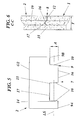
Fig. 2 ; - Fig. 4
- is a cross-section along line B-B through the first building element of
Fig. 2 ; - Fig. 5
- is a plan view of a second building element included in the building structure of
Fig. 1 ; - Fig. 6
- is a cross-section along line C-C in
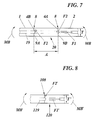
Fig. 1 through a joint formed in the building structure; - Fig. 7
- is a schematical illustration of the course of forces in a building structure according to
Fig. 1 , formed by building elements tensioned together at a staggered joint; and - Fig. 8
- is a schematical illustration of the course of forces in a building structure formed by building elements tensioned together at a straight joint.
- The principles of the present technology will now be explained with reference to exemplifying configurations thereof, which are illustrated in the attached drawing
figures 1-7 . The basic embodiment illustrated in the drawings is an example of an application of the principles of the present technology at a widely used slab of preferably concrete. The slab that is not specified in detail, is intended for forming a base or footing in a building. It shall be emphasized though, that the purpose of the shown embodiment is only to illustrate a presently preferred configuration of this technology and is not intended to limit the technology to the details shown in the drawings. It shall also be stressed that the technology is not restricted only to the building industry or to concrete as material of the structure. The technology may with the corresponding advantages be applied to other fields in order to form strong foundations or for structures consisting of other materials having similar properties of material. Such applications may however require some adaption to the use of the structures in question and/or to properties of material. - As mentioned, no solutions have been presented in the general technical field, which have managed to eliminate the problems relating to building structures that were discussed in the introduction. The new technology aims at finding an effective and reliable solution to these problems and not least to the problems of providing a building structure involving an essentially shorter delivery time than the on-site built structures of today and still having comparable strength. These objects are achieved with the new technology by applying a completely new way of thinking that basically involves forming a building structure by stably joining a number of prefabricated transportable building elements.
- This technology will now be described in more detail below with reference to a partly schematical exemplifying embodiment of a building structure. In
Figs. 1-7 is illustrated an embodiment of a building structure that is configured in accordance with the now suggested technology and inFig. 1 is especially shown a very schematical view of an exemplifyingbuilding structure 20 in a design especially intended for use in forming any type of appropriate foundation, footing or corresponding structure within the building industry. The building structure shown here is specifically intended to be prefabricated by concrete casting. - According to the technology described herein, the
building structure 20 comprises a number of adjoiningbuilding elements joint 8 and a number oftension elements 18 that apply a uniting force F1 to the respective adjoining building elements. In this embodiment is shown two adjoining and joined togetherbuilding elements - The
building structure 20 is thus formed of afirst building element 1 that at least at aportion 3 of its outer circumference O1 is fitted with afirst engagement formation 4 formed having alternatingpeaks 4A andvalleys 4B and asecond building elements 2 that at least at aportion 7 of itsouter circumference 02 likewise is fitted with asecond engagement formation 9 that in a corresponding manner is formed having alternatingpeaks 9A andvalleys 9B. It is essential that the first andsecond engagement formations second building elements joint 8 having appropriate strength in the manner described below. - With reference to
Fig. 1 and especially toFigs. 2 and5 thepeaks valleys engagement formations building structure 20 have a height A that is important to the strength of the joined together buildingstructure 20 and also to the compressive forces that arise in thebuilding elements peaks valleys second engagement formations Figs. 7 and 8 . However, in a practical example this distance may generally be said to lie between approximately 5 and 80 % of the length LE of the respective building element in a direction transversal to the joint 8, preferably between approximatelyca 20 and 50 % of this length. On the other hand, the measure A is normally chosen so as to not be larger than for the joint 8 to become equally strong with thebuilding elements - Furthermore, in the shown embodiment the first and
second engagement formations building structure 20 havepeaks valleys - In the basic embodiment with joined together building
elements tension elements 18 are used in thebuilding structure 20. Preferably, thetension elements 18 each consist of an at least partially threadedtension bar 18. The tension bars 18 are received with clearance through alignedholes 19 in adjoiningbuilding elements building elements peaks valleys engagement formations building elements - As is illustrated in the drawings and most clearly in
Fig. 6 , each of the separate, adjoiningbuilding elements building structure 20 are in conjunction with the joint 8 provided with a number of transverse force supports 16, 17 that are separated in a general longitudinal direction LS of thejoint 8. The transverse force supports 16, 17 are here made having the form of agroove 17 in thevalleys second building elements tongue 16 in thepeaks second building elements building elements tongue 16 and agroove 17 are only provided in the surfaces that lie perpendicular to the bending moment MB (Fig. 7 ) but for specific applications with special circumstances it is also possible to provide them also in other surfaces of thejoint 8. - Generally, it may be seen that when the distance A increases the compressive forces F2 (see
Fig. 7 ) are reduced in the building element material, i.e. usually in the concrete. Should the measure A be doubled the compressive forces in the material/concrete would as an example be reduced to half. Concrete only takes up compressive forces whereas tensioning forces are taken up by the material, preferably steel, of thetension rods 18 or the like. With specific reference toFigure 7 it is realized that the staggered orirregular joint 8 of a dividedbuilding structure 20, as suggested in accordance with the new technology, provides considerable advantages with regard to the ability of a building structure formed ofseparate building elements thin building structures 20 the thickness T in practice loses its importance. In comparison it is schematically illustrated inFig. 8 how a straight joint 108, i.e. having the measure A=0, should have capacity to transfer a bending moment MB'. In this case is shown how the compressive load F2' has an unfavorable effect on abuilding structure 120 at the straight joint 108. In such a case the thickness T' of the building structure/concrete slab 120 is on the contrary quite decisive of the ability to securely take up the compressive forces. - A joint 8 formed between adjoining
building elements building structure 20 according to the new technology is thus characterized by afirst engagement formation 4 with alternatingpeaks 4A andvalleys 4B at aportion 3 of an outer circumference O1 of afirst building element 1 and asecond engagement formation 9 with alternatingpeaks 9A andvalleys 9B at aportion 7 of anouter circumference 02 of asecond building element 2. The respective first and second engagement formations of the first and second building elements thereby have a mutually fitting complementary shape. In conjunction with the joint each of the adjoiningbuilding elements - The described technology finally includes also a method of forming a
building structure 20 as specified above, whereby a number of adjoiningbuilding elements tension elements 18 to the building elements that are joined together at the joint. Afirst building element 1 is at least at aportion 3 of its outer circumference O1 made/fitted with afirst engagement formation 4 that is formed having alternatingpeaks 4A andvalleys 4B. Furthermore, asecond building element 2 is at least at aportion 7 of itsouter circumference 02 made/fitted with asecond engagement formation 9 that is likewise formed having alternatingpeaks 9A andvalleys 9B. The respective first and second engagement formations of the first and second building elements are thereby formed having mutually fitting complementary shape and the first and second engagement formations are brought together and are tensioned together by thetension elements 18 to form thejoint 8. - The first and
second engagement formations peaks valleys joint 8. Thesepeaks valleys second engagement formations side surfaces - At least one partially threaded
tension bar 18 is extended with clearance throughholes 19 formed in adjoiningbuilding elements building elements joint 8. - These described, basic configurations bring about advantages in the form of:
- a very stable and above all moment resisting, composite building structure having a strength comparable to that of a concrete slab cast in one piece;
- an improved flexibility by the forming of building structures having for example different shape; and
- a cost effective solution with regard to both fabrication, transport and installation.
- Compared to the present technique consisting of concrete slabs cast on-site a divided concrete slab according to this new technology may in particular be prefabricated and may very quickly and economically be transported to and installed at a building site. The building structure according to this technology may also be dismounted and reinstalled again in another place. It is also possible to easily implement it as a divided slab with cast-in drains, water pipes, and floor heating, which is an important and large market. The delivery time from storage may probably be reduced to a week. As mentioned, this is a quite significantly shorter delivery time than for a concrete slab cast on-site. An installation time of approximately an hour may be calculated with, which all in all gives a very advantageous total time.
- Such a divided concrete slab is also very moment resisting and the strength may be maintained comparable to that of a concrete slab that is cast in one piece. Whereas it is very expensive, if at all possible, to transport a complete concrete slab the moment resisting, divided concrete slab makes normal economical transports possible. Further advantages are that the divided concrete slab according to the new technology may be prefabricated, which leads to lower price and more uniform quality, and that it may even be transported together with a building kit or the like.
- In alternative, but not specifically shown embodiments of this technology variants or modifications of different illustrated parts of the building structure formed by the building elements and of the joint, respectively, between these building elements may be used without departing from its scope. Above all, the technology is not limited to the illustrated and described, schematical configuration where the complementary engagement formations have the illustrated general trapezoidal shape of its peaks and valleys. It also comprises variants and modifications providing the same basic functions as described above, but having engagement formations with other designs of details. The same applies to embodiments where building elements have engagement formations at more than one portion of their circumference, for forming larger connected structures. Although the technology is presently estimated to have its principal application by cast concrete structures it may also come to use for materials having similar properties of material and for other purposes. The basic principles of the described technology may thus be applied to other types of building elements and in applicable cases to other types of applications than just foundations and footings.
- The technology has been described in connection with what is presently regarded as a most practical and preferred embodiment, but it shall be realized that the technology is not limited to the illustrated and described configurations. The present technology shall thus cover different modifications and equivalent arrangements that fall within the basic idea and protective scope of the attached claims.
Claims (12)
- A method of forming a building structure (20), whereby a number of separate, adjoining building elements (1, 2) are brought together, a joint (8) is formed between them and a uniting force (F1) is applied by tension elements (18) to the building elements that are joined at the joint, whereby a first building element (1) at least at a portion (3) of its outer circumference (O1) is fitted with a first engagement formation (4) that is formed having alternating peaks (4A) and valleys (4B) and a second building element (2) at least at a portion (7) of its outer circumference (02) is fitted with a second engagement formation (9) that is likewise formed having alternating peaks (9A) and valleys (9B) and whereby the first and second engagement formations of the respective first and second building elements are formed having mutually fitting complementary shape and the first and second engagement formations are brought together and are clamped together by the tension elements to form the joint, characterized by providing at each of the adjoining building elements (1, 2), in conjunction with the joint (8), a number of transverse force supports (16, 17) separated in a general longitudinal direction (LS) of the joint (8) and provided in the form of a pair of a groove and a tongue (17, 16) for each peak (4A and 9A, respectively) and valley (4B and 9B, respectively) of the engagement formations that are combined in a joined condition.
- A method according to claim 1, characterized by providing transverse force supports (16, 17) in the form of a groove (17) in the valleys (4B and 9B, respectively) of the first and second building elements and in the form of a protruding tongue (16) in the peaks (4A and 9A, respectively) of the first and second building elements and in that the number of transverse force supports (16, 17) that are provided at the building elements (1, 2) is varied depending upon the circumstances at the specific application.
- A method according to claim 1 or 2, characterized by forming each of the first and second engagement formations (4, 9) having outer (12, 14) and inner (13, 15) end surfaces, respectively, of their peaks (4A, 9A) and valleys (4B, 9B) provided at a mutual distance (A) between approximately 5 and 80 %, preferably between approximately 20 and 50 %, of the length (LE) of the building elements (1, 2) in a direction transversal to the joint (8).
- A method according to any of claims 1-3, characterized by forming the peaks (4A, 9A) and valleys (4B, 9B) of the first and second engagement formations (4, 9) having straight or alternatively outwardly generally converging and diverging, respectively side surfaces (5, 10).
- A method according to any of claims 1-4, characterized by extending at least one partially threaded tension rod (18) with clearance through holes (19) formed in adjoining building elements (1, 2) and tensioning it with tensioning force (F1) against each of these building elements.
- A building structure (20) including a number of separate, adjoining building elements (1, 2) that are brought together at a joint (8) and a number of tension elements (18) that apply a uniting force (F1) to the respective adjoining building elements, whereby a first building element (1) at least at a portion (3) of its outer circumference (O1) is fitted with a first engagement formation (4) that is formed having alternating peaks (4A) and valleys (4B) and a second building element (2) at least at a portion (7) of its outer circumference (02) is fitted with a second engagement formation (9) that is likewise formed having alternating peaks (9A) and valleys (9B) and whereby the first and second engagement formations of the respective first and second building elements are formed having mutually fitting complementary shape, characterized in that in conjunction with the joint (8) each of the adjoining building elements (1, 2) is fitted with a number of transverse force supports (16, 17) that are separated in a general longitudinal direction (LS) of the joint (8) and that are in the form of a pair of a groove and a tongue (17, 16) for each peak (4A and 9A, respectively) and valley (4B and 9B, respectively) of the engagement formations that are combined in a joined condition.
- A building structure (20) according to claim 6, characterized in that the transverse force supports (16, 17) are in the form of a groove (17) in the valleys (4B and 9B, respectively) of the first and second building elements and in the form of a protruding tongue (16) in the peaks (4A and 9A, respectively) of the first and second building elements and in that the transverse force supports (16, 17) are provided at the building elements (1, 2) in a number that varies depending upon the circumstances at the specific application.
- A building structure (20) according to claims 6 or 7, characterized in that outer (12, 14) and inner (13, 15) end surfaces, respectively, of the alternating peaks (4A, 9A) and valleys (4B, 9B) of the first and second engagement formations (4, 9) are provided at a mutual distance (A) of between approximately 5 and 80 %, preferably between approximately 20 and 50 %, of the length (LE) of the respective building element in a direction transversal to the joint (8).
- A building structure (20) according to any of claims 6 - 8, characterized in that the peaks (4A, 9A) and valleys (4B, 9B) of the first and second engagement formations (4, 9) have straight or alternatively outwardly generally converging and diverging, respectively, side surfaces (5, 10).
- A building structure (20) according to any of claims 6 - 9, characterized in that the tension element/elements (18) consists/consist of a partially threaded tension rod (18) that is received with clearance through holes (19) in adjoining building elements (1, 2) and is tensioned with a tensioning force (F1) against each of these building elements.
- A joint (8) between separate adjoining building elements (1, 2) in a building structure (20), including a first engagement formation (4) with alternating peaks (4A) and valleys (4B) at a portion (3) of an outer circumference (O1) of a first building element (1) and a second engagement formation (9) with alternating peaks (9A) and valleys (9B) at a portion (7) of an outer circumference (02) of a second building element (2), whereby the respective first and second engagement formations of the first and second building elements have a mutually fitting complementary shape, characterized in that in conjunction with the joint (8) each of the adjoining building elements (1, 2) is fitted with a number of transverse force supports (16, 17) that are separated in a general longitudinal direction (LS) of the joint (8) and that are in the form of a pair of a groove and a tongue (17, 16) for each peak (4A and 9A, respectively) and valley (4B and 9B, respectively) of the engagement formations that are combined in a joined condition.
- A joint (8) between building elements according to claim 11, characterized in that the transverse force supports (16, 17) are in the shape of a groove (17) in the valleys (4B and 9B, respectively) of the first and second building elements and in the form of a protruding tongue (16) in the peaks (4A and 9A, respectively) of the first and second building elements and in that the transverse force supports (16, 17) are provided at the building elements (1, 2) in a number that varies depending upon the circumstances at the specific application.
Applications Claiming Priority (1)
| Application Number | Priority Date | Filing Date | Title |
|---|---|---|---|
| SE1450412A SE539783C2 (en) | 2014-04-04 | 2014-04-04 | Building structure formed of building elements, method of forming a building structure and a joint |
Publications (2)
| Publication Number | Publication Date |
|---|---|
| EP2927381A1 true EP2927381A1 (en) | 2015-10-07 |
| EP2927381B1 EP2927381B1 (en) | 2018-05-16 |
Family
ID=52726980
Family Applications (1)
| Application Number | Title | Priority Date | Filing Date |
|---|---|---|---|
| EP15159450.4A Not-in-force EP2927381B1 (en) | 2014-04-04 | 2015-03-17 | A building structure formed of building elements |
Country Status (2)
| Country | Link |
|---|---|
| EP (1) | EP2927381B1 (en) |
| SE (1) | SE539783C2 (en) |
Citations (4)
| Publication number | Priority date | Publication date | Assignee | Title |
|---|---|---|---|---|
| US2241169A (en) * | 1937-12-08 | 1941-05-06 | Yokes Otto | Building construction |
| US20050072115A1 (en) * | 2003-09-19 | 2005-04-07 | Chappell Ralph Louis | Preformed portable slab for use as a foundation or splash pad for industrial equipment |
| US20100154332A1 (en) * | 2008-12-23 | 2010-06-24 | Chevron U.S.A. Inc. | Base mat assembly and method of constructing the same |
| WO2011034603A2 (en) * | 2009-09-16 | 2011-03-24 | Pre-Con Products, Ltd. | Modular foundation system and method |
-
2014
- 2014-04-04 SE SE1450412A patent/SE539783C2/en not_active IP Right Cessation
-
2015
- 2015-03-17 EP EP15159450.4A patent/EP2927381B1/en not_active Not-in-force
Patent Citations (4)
| Publication number | Priority date | Publication date | Assignee | Title |
|---|---|---|---|---|
| US2241169A (en) * | 1937-12-08 | 1941-05-06 | Yokes Otto | Building construction |
| US20050072115A1 (en) * | 2003-09-19 | 2005-04-07 | Chappell Ralph Louis | Preformed portable slab for use as a foundation or splash pad for industrial equipment |
| US20100154332A1 (en) * | 2008-12-23 | 2010-06-24 | Chevron U.S.A. Inc. | Base mat assembly and method of constructing the same |
| WO2011034603A2 (en) * | 2009-09-16 | 2011-03-24 | Pre-Con Products, Ltd. | Modular foundation system and method |
Also Published As
| Publication number | Publication date |
|---|---|
| SE539783C2 (en) | 2017-11-28 |
| EP2927381B1 (en) | 2018-05-16 |
| SE1450412A1 (en) | 2015-10-05 |
Similar Documents
| Publication | Publication Date | Title |
|---|---|---|
| AU659163B2 (en) | Sheet metal structural member, construction panel and method of construction | |
| US8911173B2 (en) | Pavement slabs with sliding dowels | |
| CA2697085C (en) | Shuttering | |
| US9234350B1 (en) | System and method of constructing a composite assembly | |
| BR112016017131B1 (en) | THREE-DIMENSIONAL LIGHTWEIGHT STEEL STRUCTURE FORMED BY TWO-WAY CONTINUOUS DOUBLE BEAMS | |
| KR101184226B1 (en) | Apparatus for connecting reinforced steel net structure and construction method thereof | |
| US9297161B2 (en) | Roof member anti-torsion bracket device and method of use | |
| CN107237402A (en) | A kind of low damage Self-resetting assembly concrete two-way frame bean column node | |
| US9957686B2 (en) | Modular foundation system and method | |
| WO2014193323A1 (en) | Shear and bending reinforcements of coupling beams of coupled shear walls | |
| CN104153463B (en) | Assembled integrated frame system and construction method thereof | |
| EP2927381B1 (en) | A building structure formed of building elements | |
| CN105155690A (en) | Connection node of precast slabs and construction method for spliced precast slabs | |
| CN209443654U (en) | Assembled large span T plate building prefabricated components | |
| US3683581A (en) | Prefabricated frame | |
| JP4566138B2 (en) | Soil cement composite pile | |
| WO2014204419A2 (en) | Coupling beam to coupled shear (hollow) wall connection system | |
| CN206299126U (en) | A kind of assembled plate-column structure floor and floor panels component | |
| RU2358068C1 (en) | Joint connection of crossing rods | |
| KR101832291B1 (en) | Reinforced Concrete Composite Corrugated Steel Shear Reinforced Structures Combined with Fastening Members for Stiffness Improvement | |
| JP4884200B2 (en) | Seismic reinforcement structure for existing columns and construction method of the seismic reinforcement structure | |
| CN203307800U (en) | Built-in anti-corrosion structure for pre-stress hollow square pile | |
| DE202012001342U1 (en) | Transport anchor for double walls | |
| KR101791177B1 (en) | Corrugated Steel Plate Web-PSC Composite Beam Structure Which Combined Corrugated Steel Plate And Concrete Plate with Bolt | |
| CN211948030U (en) | Fixed box culvert settlement joint waterstop's typical forms braced system |
Legal Events
| Date | Code | Title | Description |
|---|---|---|---|
| PUAI | Public reference made under article 153(3) epc to a published international application that has entered the european phase |
Free format text: ORIGINAL CODE: 0009012 |
|
| AK | Designated contracting states |
Kind code of ref document: A1 Designated state(s): AL AT BE BG CH CY CZ DE DK EE ES FI FR GB GR HR HU IE IS IT LI LT LU LV MC MK MT NL NO PL PT RO RS SE SI SK SM TR |
|
| AX | Request for extension of the european patent |
Extension state: BA ME |
|
| 17P | Request for examination filed |
Effective date: 20160407 |
|
| RBV | Designated contracting states (corrected) |
Designated state(s): AL AT BE BG CH CY CZ DE DK EE ES FI FR GB GR HR HU IE IS IT LI LT LU LV MC MK MT NL NO PL PT RO RS SE SI SK SM TR |
|
| STAA | Information on the status of an ep patent application or granted ep patent |
Free format text: STATUS: EXAMINATION IS IN PROGRESS |
|
| 17Q | First examination report despatched |
Effective date: 20170404 |
|
| GRAP | Despatch of communication of intention to grant a patent |
Free format text: ORIGINAL CODE: EPIDOSNIGR1 |
|
| STAA | Information on the status of an ep patent application or granted ep patent |
Free format text: STATUS: GRANT OF PATENT IS INTENDED |
|
| INTG | Intention to grant announced |
Effective date: 20171204 |
|
| GRAS | Grant fee paid |
Free format text: ORIGINAL CODE: EPIDOSNIGR3 |
|
| GRAA | (expected) grant |
Free format text: ORIGINAL CODE: 0009210 |
|
| STAA | Information on the status of an ep patent application or granted ep patent |
Free format text: STATUS: THE PATENT HAS BEEN GRANTED |
|
| AK | Designated contracting states |
Kind code of ref document: B1 Designated state(s): AL AT BE BG CH CY CZ DE DK EE ES FI FR GB GR HR HU IE IS IT LI LT LU LV MC MK MT NL NO PL PT RO RS SE SI SK SM TR |
|
| REG | Reference to a national code |
Ref country code: GB Ref legal event code: FG4D |
|
| REG | Reference to a national code |
Ref country code: CH Ref legal event code: EP |
|
| REG | Reference to a national code |
Ref country code: IE Ref legal event code: FG4D |
|
| REG | Reference to a national code |
Ref country code: DE Ref legal event code: R096 Ref document number: 602015011076 Country of ref document: DE |
|
| REG | Reference to a national code |
Ref country code: AT Ref legal event code: REF Ref document number: 999699 Country of ref document: AT Kind code of ref document: T Effective date: 20180615 |
|
| REG | Reference to a national code |
Ref country code: NL Ref legal event code: MP Effective date: 20180516 |
|
| REG | Reference to a national code |
Ref country code: LT Ref legal event code: MG4D |
|
| PG25 | Lapsed in a contracting state [announced via postgrant information from national office to epo] |
Ref country code: BG Free format text: LAPSE BECAUSE OF FAILURE TO SUBMIT A TRANSLATION OF THE DESCRIPTION OR TO PAY THE FEE WITHIN THE PRESCRIBED TIME-LIMIT Effective date: 20180816 Ref country code: NO Free format text: LAPSE BECAUSE OF FAILURE TO SUBMIT A TRANSLATION OF THE DESCRIPTION OR TO PAY THE FEE WITHIN THE PRESCRIBED TIME-LIMIT Effective date: 20180816 Ref country code: SE Free format text: LAPSE BECAUSE OF FAILURE TO SUBMIT A TRANSLATION OF THE DESCRIPTION OR TO PAY THE FEE WITHIN THE PRESCRIBED TIME-LIMIT Effective date: 20180516 Ref country code: ES Free format text: LAPSE BECAUSE OF FAILURE TO SUBMIT A TRANSLATION OF THE DESCRIPTION OR TO PAY THE FEE WITHIN THE PRESCRIBED TIME-LIMIT Effective date: 20180516 Ref country code: LT Free format text: LAPSE BECAUSE OF FAILURE TO SUBMIT A TRANSLATION OF THE DESCRIPTION OR TO PAY THE FEE WITHIN THE PRESCRIBED TIME-LIMIT Effective date: 20180516 |
|
| PG25 | Lapsed in a contracting state [announced via postgrant information from national office to epo] |
Ref country code: NL Free format text: LAPSE BECAUSE OF FAILURE TO SUBMIT A TRANSLATION OF THE DESCRIPTION OR TO PAY THE FEE WITHIN THE PRESCRIBED TIME-LIMIT Effective date: 20180516 Ref country code: HR Free format text: LAPSE BECAUSE OF FAILURE TO SUBMIT A TRANSLATION OF THE DESCRIPTION OR TO PAY THE FEE WITHIN THE PRESCRIBED TIME-LIMIT Effective date: 20180516 Ref country code: GR Free format text: LAPSE BECAUSE OF FAILURE TO SUBMIT A TRANSLATION OF THE DESCRIPTION OR TO PAY THE FEE WITHIN THE PRESCRIBED TIME-LIMIT Effective date: 20180817 Ref country code: LV Free format text: LAPSE BECAUSE OF FAILURE TO SUBMIT A TRANSLATION OF THE DESCRIPTION OR TO PAY THE FEE WITHIN THE PRESCRIBED TIME-LIMIT Effective date: 20180516 Ref country code: RS Free format text: LAPSE BECAUSE OF FAILURE TO SUBMIT A TRANSLATION OF THE DESCRIPTION OR TO PAY THE FEE WITHIN THE PRESCRIBED TIME-LIMIT Effective date: 20180516 |
|
| REG | Reference to a national code |
Ref country code: AT Ref legal event code: MK05 Ref document number: 999699 Country of ref document: AT Kind code of ref document: T Effective date: 20180516 |
|
| PG25 | Lapsed in a contracting state [announced via postgrant information from national office to epo] |
Ref country code: DK Free format text: LAPSE BECAUSE OF FAILURE TO SUBMIT A TRANSLATION OF THE DESCRIPTION OR TO PAY THE FEE WITHIN THE PRESCRIBED TIME-LIMIT Effective date: 20180516 Ref country code: EE Free format text: LAPSE BECAUSE OF FAILURE TO SUBMIT A TRANSLATION OF THE DESCRIPTION OR TO PAY THE FEE WITHIN THE PRESCRIBED TIME-LIMIT Effective date: 20180516 Ref country code: CZ Free format text: LAPSE BECAUSE OF FAILURE TO SUBMIT A TRANSLATION OF THE DESCRIPTION OR TO PAY THE FEE WITHIN THE PRESCRIBED TIME-LIMIT Effective date: 20180516 Ref country code: AT Free format text: LAPSE BECAUSE OF FAILURE TO SUBMIT A TRANSLATION OF THE DESCRIPTION OR TO PAY THE FEE WITHIN THE PRESCRIBED TIME-LIMIT Effective date: 20180516 Ref country code: SK Free format text: LAPSE BECAUSE OF FAILURE TO SUBMIT A TRANSLATION OF THE DESCRIPTION OR TO PAY THE FEE WITHIN THE PRESCRIBED TIME-LIMIT Effective date: 20180516 Ref country code: RO Free format text: LAPSE BECAUSE OF FAILURE TO SUBMIT A TRANSLATION OF THE DESCRIPTION OR TO PAY THE FEE WITHIN THE PRESCRIBED TIME-LIMIT Effective date: 20180516 Ref country code: PL Free format text: LAPSE BECAUSE OF FAILURE TO SUBMIT A TRANSLATION OF THE DESCRIPTION OR TO PAY THE FEE WITHIN THE PRESCRIBED TIME-LIMIT Effective date: 20180516 |
|
| REG | Reference to a national code |
Ref country code: DE Ref legal event code: R097 Ref document number: 602015011076 Country of ref document: DE |
|
| PG25 | Lapsed in a contracting state [announced via postgrant information from national office to epo] |
Ref country code: IT Free format text: LAPSE BECAUSE OF FAILURE TO SUBMIT A TRANSLATION OF THE DESCRIPTION OR TO PAY THE FEE WITHIN THE PRESCRIBED TIME-LIMIT Effective date: 20180516 Ref country code: SM Free format text: LAPSE BECAUSE OF FAILURE TO SUBMIT A TRANSLATION OF THE DESCRIPTION OR TO PAY THE FEE WITHIN THE PRESCRIBED TIME-LIMIT Effective date: 20180516 |
|
| PLBE | No opposition filed within time limit |
Free format text: ORIGINAL CODE: 0009261 |
|
| STAA | Information on the status of an ep patent application or granted ep patent |
Free format text: STATUS: NO OPPOSITION FILED WITHIN TIME LIMIT |
|
| 26N | No opposition filed |
Effective date: 20190219 |
|
| PG25 | Lapsed in a contracting state [announced via postgrant information from national office to epo] |
Ref country code: SI Free format text: LAPSE BECAUSE OF FAILURE TO SUBMIT A TRANSLATION OF THE DESCRIPTION OR TO PAY THE FEE WITHIN THE PRESCRIBED TIME-LIMIT Effective date: 20180516 |
|
| REG | Reference to a national code |
Ref country code: DE Ref legal event code: R119 Ref document number: 602015011076 Country of ref document: DE |
|
| PG25 | Lapsed in a contracting state [announced via postgrant information from national office to epo] |
Ref country code: MC Free format text: LAPSE BECAUSE OF FAILURE TO SUBMIT A TRANSLATION OF THE DESCRIPTION OR TO PAY THE FEE WITHIN THE PRESCRIBED TIME-LIMIT Effective date: 20180516 |
|
| REG | Reference to a national code |
Ref country code: CH Ref legal event code: PL |
|
| GBPC | Gb: european patent ceased through non-payment of renewal fee |
Effective date: 20190317 |
|
| PG25 | Lapsed in a contracting state [announced via postgrant information from national office to epo] |
Ref country code: LU Free format text: LAPSE BECAUSE OF NON-PAYMENT OF DUE FEES Effective date: 20190317 Ref country code: AL Free format text: LAPSE BECAUSE OF FAILURE TO SUBMIT A TRANSLATION OF THE DESCRIPTION OR TO PAY THE FEE WITHIN THE PRESCRIBED TIME-LIMIT Effective date: 20180516 |
|
| REG | Reference to a national code |
Ref country code: BE Ref legal event code: MM Effective date: 20190331 |
|
| PG25 | Lapsed in a contracting state [announced via postgrant information from national office to epo] |
Ref country code: LI Free format text: LAPSE BECAUSE OF NON-PAYMENT OF DUE FEES Effective date: 20190331 Ref country code: DE Free format text: LAPSE BECAUSE OF NON-PAYMENT OF DUE FEES Effective date: 20191001 Ref country code: IE Free format text: LAPSE BECAUSE OF NON-PAYMENT OF DUE FEES Effective date: 20190317 Ref country code: CH Free format text: LAPSE BECAUSE OF NON-PAYMENT OF DUE FEES Effective date: 20190331 Ref country code: GB Free format text: LAPSE BECAUSE OF NON-PAYMENT OF DUE FEES Effective date: 20190317 |
|
| PG25 | Lapsed in a contracting state [announced via postgrant information from national office to epo] |
Ref country code: FR Free format text: LAPSE BECAUSE OF NON-PAYMENT OF DUE FEES Effective date: 20190331 Ref country code: BE Free format text: LAPSE BECAUSE OF NON-PAYMENT OF DUE FEES Effective date: 20190331 |
|
| PG25 | Lapsed in a contracting state [announced via postgrant information from national office to epo] |
Ref country code: TR Free format text: LAPSE BECAUSE OF FAILURE TO SUBMIT A TRANSLATION OF THE DESCRIPTION OR TO PAY THE FEE WITHIN THE PRESCRIBED TIME-LIMIT Effective date: 20180516 |
|
| PGFP | Annual fee paid to national office [announced via postgrant information from national office to epo] |
Ref country code: FI Payment date: 20200316 Year of fee payment: 6 |
|
| PG25 | Lapsed in a contracting state [announced via postgrant information from national office to epo] |
Ref country code: PT Free format text: LAPSE BECAUSE OF FAILURE TO SUBMIT A TRANSLATION OF THE DESCRIPTION OR TO PAY THE FEE WITHIN THE PRESCRIBED TIME-LIMIT Effective date: 20180917 Ref country code: MT Free format text: LAPSE BECAUSE OF NON-PAYMENT OF DUE FEES Effective date: 20190317 |
|
| PG25 | Lapsed in a contracting state [announced via postgrant information from national office to epo] |
Ref country code: CY Free format text: LAPSE BECAUSE OF FAILURE TO SUBMIT A TRANSLATION OF THE DESCRIPTION OR TO PAY THE FEE WITHIN THE PRESCRIBED TIME-LIMIT Effective date: 20180516 |
|
| PG25 | Lapsed in a contracting state [announced via postgrant information from national office to epo] |
Ref country code: IS Free format text: LAPSE BECAUSE OF FAILURE TO SUBMIT A TRANSLATION OF THE DESCRIPTION OR TO PAY THE FEE WITHIN THE PRESCRIBED TIME-LIMIT Effective date: 20180916 |
|
| PG25 | Lapsed in a contracting state [announced via postgrant information from national office to epo] |
Ref country code: HU Free format text: LAPSE BECAUSE OF FAILURE TO SUBMIT A TRANSLATION OF THE DESCRIPTION OR TO PAY THE FEE WITHIN THE PRESCRIBED TIME-LIMIT; INVALID AB INITIO Effective date: 20150317 |
|
| REG | Reference to a national code |
Ref country code: FI Ref legal event code: MAE |
|
| PG25 | Lapsed in a contracting state [announced via postgrant information from national office to epo] |
Ref country code: FI Free format text: LAPSE BECAUSE OF NON-PAYMENT OF DUE FEES Effective date: 20210317 |
|
| PG25 | Lapsed in a contracting state [announced via postgrant information from national office to epo] |
Ref country code: MK Free format text: LAPSE BECAUSE OF FAILURE TO SUBMIT A TRANSLATION OF THE DESCRIPTION OR TO PAY THE FEE WITHIN THE PRESCRIBED TIME-LIMIT Effective date: 20180516 |