EP2927068A2 - Brake system and method of control with air gap estimation - Google Patents
Brake system and method of control with air gap estimation Download PDFInfo
- Publication number
- EP2927068A2 EP2927068A2 EP15155613.1A EP15155613A EP2927068A2 EP 2927068 A2 EP2927068 A2 EP 2927068A2 EP 15155613 A EP15155613 A EP 15155613A EP 2927068 A2 EP2927068 A2 EP 2927068A2
- Authority
- EP
- European Patent Office
- Prior art keywords
- brake
- air gap
- pad assembly
- brake pad
- friction member
- Prior art date
- Legal status (The legal status is an assumption and is not a legal conclusion. Google has not performed a legal analysis and makes no representation as to the accuracy of the status listed.)
- Granted
Links
Images

Classifications
-
- B—PERFORMING OPERATIONS; TRANSPORTING
- B60—VEHICLES IN GENERAL
- B60T—VEHICLE BRAKE CONTROL SYSTEMS OR PARTS THEREOF; BRAKE CONTROL SYSTEMS OR PARTS THEREOF, IN GENERAL; ARRANGEMENT OF BRAKING ELEMENTS ON VEHICLES IN GENERAL; PORTABLE DEVICES FOR PREVENTING UNWANTED MOVEMENT OF VEHICLES; VEHICLE MODIFICATIONS TO FACILITATE COOLING OF BRAKES
- B60T13/00—Transmitting braking action from initiating means to ultimate brake actuator with power assistance or drive; Brake systems incorporating such transmitting means, e.g. air-pressure brake systems
- B60T13/10—Transmitting braking action from initiating means to ultimate brake actuator with power assistance or drive; Brake systems incorporating such transmitting means, e.g. air-pressure brake systems with fluid assistance, drive, or release
- B60T13/66—Electrical control in fluid-pressure brake systems
- B60T13/662—Electrical control in fluid-pressure brake systems characterised by specified functions of the control system components
-
- B—PERFORMING OPERATIONS; TRANSPORTING
- B60—VEHICLES IN GENERAL
- B60T—VEHICLE BRAKE CONTROL SYSTEMS OR PARTS THEREOF; BRAKE CONTROL SYSTEMS OR PARTS THEREOF, IN GENERAL; ARRANGEMENT OF BRAKING ELEMENTS ON VEHICLES IN GENERAL; PORTABLE DEVICES FOR PREVENTING UNWANTED MOVEMENT OF VEHICLES; VEHICLE MODIFICATIONS TO FACILITATE COOLING OF BRAKES
- B60T13/00—Transmitting braking action from initiating means to ultimate brake actuator with power assistance or drive; Brake systems incorporating such transmitting means, e.g. air-pressure brake systems
- B60T13/74—Transmitting braking action from initiating means to ultimate brake actuator with power assistance or drive; Brake systems incorporating such transmitting means, e.g. air-pressure brake systems with electrical assistance or drive
-
- B—PERFORMING OPERATIONS; TRANSPORTING
- B60—VEHICLES IN GENERAL
- B60T—VEHICLE BRAKE CONTROL SYSTEMS OR PARTS THEREOF; BRAKE CONTROL SYSTEMS OR PARTS THEREOF, IN GENERAL; ARRANGEMENT OF BRAKING ELEMENTS ON VEHICLES IN GENERAL; PORTABLE DEVICES FOR PREVENTING UNWANTED MOVEMENT OF VEHICLES; VEHICLE MODIFICATIONS TO FACILITATE COOLING OF BRAKES
- B60T17/00—Component parts, details, or accessories of power brake systems not covered by groups B60T8/00, B60T13/00 or B60T15/00, or presenting other characteristic features
- B60T17/18—Safety devices; Monitoring
- B60T17/22—Devices for monitoring or checking brake systems; Signal devices
-
- B—PERFORMING OPERATIONS; TRANSPORTING
- B60—VEHICLES IN GENERAL
- B60T—VEHICLE BRAKE CONTROL SYSTEMS OR PARTS THEREOF; BRAKE CONTROL SYSTEMS OR PARTS THEREOF, IN GENERAL; ARRANGEMENT OF BRAKING ELEMENTS ON VEHICLES IN GENERAL; PORTABLE DEVICES FOR PREVENTING UNWANTED MOVEMENT OF VEHICLES; VEHICLE MODIFICATIONS TO FACILITATE COOLING OF BRAKES
- B60T7/00—Brake-action initiating means
- B60T7/12—Brake-action initiating means for automatic initiation; for initiation not subject to will of driver or passenger
- B60T7/22—Brake-action initiating means for automatic initiation; for initiation not subject to will of driver or passenger initiated by contact of vehicle, e.g. bumper, with an external object, e.g. another vehicle, or by means of contactless obstacle detectors mounted on the vehicle
-
- F—MECHANICAL ENGINEERING; LIGHTING; HEATING; WEAPONS; BLASTING
- F16—ENGINEERING ELEMENTS AND UNITS; GENERAL MEASURES FOR PRODUCING AND MAINTAINING EFFECTIVE FUNCTIONING OF MACHINES OR INSTALLATIONS; THERMAL INSULATION IN GENERAL
- F16D—COUPLINGS FOR TRANSMITTING ROTATION; CLUTCHES; BRAKES
- F16D55/00—Brakes with substantially-radial braking surfaces pressed together in axial direction, e.g. disc brakes
- F16D55/02—Brakes with substantially-radial braking surfaces pressed together in axial direction, e.g. disc brakes with axially-movable discs or pads pressed against axially-located rotating members
- F16D55/22—Brakes with substantially-radial braking surfaces pressed together in axial direction, e.g. disc brakes with axially-movable discs or pads pressed against axially-located rotating members by clamping an axially-located rotating disc between movable braking members, e.g. movable brake discs or brake pads
- F16D55/224—Brakes with substantially-radial braking surfaces pressed together in axial direction, e.g. disc brakes with axially-movable discs or pads pressed against axially-located rotating members by clamping an axially-located rotating disc between movable braking members, e.g. movable brake discs or brake pads with a common actuating member for the braking members
- F16D55/225—Brakes with substantially-radial braking surfaces pressed together in axial direction, e.g. disc brakes with axially-movable discs or pads pressed against axially-located rotating members by clamping an axially-located rotating disc between movable braking members, e.g. movable brake discs or brake pads with a common actuating member for the braking members the braking members being brake pads
- F16D55/226—Brakes with substantially-radial braking surfaces pressed together in axial direction, e.g. disc brakes with axially-movable discs or pads pressed against axially-located rotating members by clamping an axially-located rotating disc between movable braking members, e.g. movable brake discs or brake pads with a common actuating member for the braking members the braking members being brake pads in which the common actuating member is moved axially, e.g. floating caliper disc brakes
-
- F—MECHANICAL ENGINEERING; LIGHTING; HEATING; WEAPONS; BLASTING
- F16—ENGINEERING ELEMENTS AND UNITS; GENERAL MEASURES FOR PRODUCING AND MAINTAINING EFFECTIVE FUNCTIONING OF MACHINES OR INSTALLATIONS; THERMAL INSULATION IN GENERAL
- F16D—COUPLINGS FOR TRANSMITTING ROTATION; CLUTCHES; BRAKES
- F16D65/00—Parts or details
- F16D65/14—Actuating mechanisms for brakes; Means for initiating operation at a predetermined position
- F16D65/16—Actuating mechanisms for brakes; Means for initiating operation at a predetermined position arranged in or on the brake
- F16D65/18—Actuating mechanisms for brakes; Means for initiating operation at a predetermined position arranged in or on the brake adapted for drawing members together, e.g. for disc brakes
-
- F—MECHANICAL ENGINEERING; LIGHTING; HEATING; WEAPONS; BLASTING
- F16—ENGINEERING ELEMENTS AND UNITS; GENERAL MEASURES FOR PRODUCING AND MAINTAINING EFFECTIVE FUNCTIONING OF MACHINES OR INSTALLATIONS; THERMAL INSULATION IN GENERAL
- F16D—COUPLINGS FOR TRANSMITTING ROTATION; CLUTCHES; BRAKES
- F16D65/00—Parts or details
- F16D65/38—Slack adjusters
- F16D65/40—Slack adjusters mechanical
- F16D65/52—Slack adjusters mechanical self-acting in one direction for adjusting excessive play
- F16D65/56—Slack adjusters mechanical self-acting in one direction for adjusting excessive play with screw-thread and nut
- F16D65/567—Slack adjusters mechanical self-acting in one direction for adjusting excessive play with screw-thread and nut for mounting on a disc brake
-
- F—MECHANICAL ENGINEERING; LIGHTING; HEATING; WEAPONS; BLASTING
- F16—ENGINEERING ELEMENTS AND UNITS; GENERAL MEASURES FOR PRODUCING AND MAINTAINING EFFECTIVE FUNCTIONING OF MACHINES OR INSTALLATIONS; THERMAL INSULATION IN GENERAL
- F16D—COUPLINGS FOR TRANSMITTING ROTATION; CLUTCHES; BRAKES
- F16D66/00—Arrangements for monitoring working conditions, e.g. wear, temperature
- F16D66/02—Apparatus for indicating wear
- F16D66/021—Apparatus for indicating wear using electrical detection or indication means
- F16D66/022—Apparatus for indicating wear using electrical detection or indication means indicating that a lining is worn to minimum allowable thickness
- F16D66/025—Apparatus for indicating wear using electrical detection or indication means indicating that a lining is worn to minimum allowable thickness sensing the position of parts of the brake system other than the braking members, e.g. limit switches mounted on master cylinders
-
- B—PERFORMING OPERATIONS; TRANSPORTING
- B60—VEHICLES IN GENERAL
- B60T—VEHICLE BRAKE CONTROL SYSTEMS OR PARTS THEREOF; BRAKE CONTROL SYSTEMS OR PARTS THEREOF, IN GENERAL; ARRANGEMENT OF BRAKING ELEMENTS ON VEHICLES IN GENERAL; PORTABLE DEVICES FOR PREVENTING UNWANTED MOVEMENT OF VEHICLES; VEHICLE MODIFICATIONS TO FACILITATE COOLING OF BRAKES
- B60T2201/00—Particular use of vehicle brake systems; Special systems using also the brakes; Special software modules within the brake system controller
- B60T2201/02—Active or adaptive cruise control system; Distance control
- B60T2201/022—Collision avoidance systems
Definitions
- This patent application relates to a brake system and method of control in which an air gap between a brake friction member and a brake pad assembly may be estimated.
- a method of controlling a brake system may include indirectly estimating an air gap between a brake friction member and a brake pad assembly based on a signal from a position sensor that detects cycling of the friction brake.
- the air gap may be adjusted when an estimated air gap exceeds a desired air gap.
- a method of controlling a brake system may include cycling a friction brake by actuating a brake pad assembly from a retracted position into engagement with a brake friction member and releasing the brake pad assembly such that the brake pad assembly disengages the brake friction member and moves toward the retracted position.
- An air gap between the brake friction member and the brake pad assembly may be indirectly estimated based on a signal from a position sensor that may be indicative of actuation of a brake pedal. The air gap may be adjusted when an estimated air gap exceeds a desired air gap.
- a brake system may include a brake friction member, a brake pad assembly, an actuator subsystem, and a position sensor.
- the brake pad assembly may be configured to move between a retracted position and an extended position. The brake pad assembly may not engage the brake friction member when in the retracted position. The brake pad assembly may engage the brake friction member when in the extended position.
- the actuator subsystem may include an operating shaft that may rotate when the brake pad assembly moves between the retracted and extended positions.
- the position sensor may detect rotation of the operating shaft. An air gap between the brake pad assembly and the brake friction member may be estimated based on a signal from the position sensor.
- the brake system 10 may be provided with a vehicle, such as a motor vehicle like a truck, farm equipment, or military transport or weaponry vehicle.
- vehicle may include a trailer for transporting cargo in one or more embodiments.
- the brake system 10 may be configured to slow or inhibit rotation of at least one associated wheel assembly.
- the brake system 10 may include a set of friction brakes 12, an actuator subsystem 14, and a control system 16.
- a friction brake 12 which may also be called a foundation brake, may be disposed proximate a wheel assembly and may be configured to slow rotation of the wheel assembly. Multiple friction brakes 12 may be provided with the vehicle and may be controlled by the control system 16.
- the friction brake 12 may have any suitable configuration.
- a friction brake 12 may be configured as a disc brake.
- the friction brake 12 may include a brake friction member 20 and at least one brake pad assembly 22.
- the brake friction member 20 may be connected to a wheel hub. As such, the brake friction member 20 may rotate with a wheel assembly and with respect to a brake pad assembly 22 when braking is not requested. In a disc brake configuration, the brake friction member 20 may be configured as a rotor, which is also known as a brake disc.
- the brake friction member 20 may extend into an opening in a carrier (not shown).
- the carrier may be fixedly mounted to the vehicle and may receive and/or support inboard and outboard brake pad assemblies 22. As such, the carrier may straddle the brake friction member 20 and help position the brake pad assemblies 22 on opposite sides of the brake friction member 20.
- the brake pad assembly 22 may engage the brake friction member 20 when braking is requested or commanded and exert frictional force against the brake friction member 20 to retard or slow rotation of an associated wheel assembly.
- inboard and outboard brake pad assemblies 22 may be disposed on opposite sides of the brake friction member 20 and may be configured to engage opposite sides of the brake friction member 20 to slow the rotation of a vehicle wheel.
- the brake pad assemblies 22 may be received in a caliper housing (not shown) that may be movably disposed on the carrier. More specifically, the caliper housing may be slidably disposed on a pair of slide pins that may be fixedly disposed on the carrier.
- the caliper housing may receive at least a portion of the actuator subsystem 14, which may actuate the brake pad assemblies 22 into engagement with the brake friction member 20.
- the actuator subsystem 14 may include one or more pistons that may actuate the inboard brake pad assembly 22 toward the brake friction member 20 and move the caliper housing to actuate the outboard brake pad assembly 22 toward the rotor as will be discussed in more detail below.
- the brake pad assembly 22 may include a backing plate 30 and a friction material 32.
- the backing plate 30 may be a structural member of a brake pad assembly 22.
- the backing plate 30 may be made of any suitable material, such as a metal or metal alloy.
- the friction material 32 which may also be called a brake lining, may be disposed on the backing plate 30.
- the friction material 32 may face toward the brake friction member 20 and may engage the brake friction member 20 during vehicle braking.
- the friction material 32 may be spaced apart from and may not engage the brake friction member 20 when the friction brake 12 is not being applied.
- the clearance or distance between the friction material 32 and the brake friction member 20 when the friction brake 12 is not being applied may be referred to as an air gap 34 or running clearance. No clearance or zero clearance may be present between the friction material 32 and the brake friction member 20 when the friction brake 12 is applied.
- the actuator subsystem 14 may be configured to actuate a brake pad assembly 22 between a retracted position and an extended position.
- the retracted position may also be referred to as an initial position or rest position.
- the brake pad assembly 22 may be spaced apart from the brake friction member 20 and may be stationary when in the retracted position. As such, a brake pad assembly 22 may be in the retracted position when the friction brake 12 is not being applied.
- the brake pad assembly 22 and more specifically the friction material 32 may engage the brake friction member 20 when in the extended position.
- the actuator subsystem 14 may be disposed proximate or provided with the caliper housing.
- the actuator subsystem 14 may have any suitable configuration.
- the actuator subsystem 14 may have a pneumatic, hydraulic, electrical, or electromechanical configuration, or combinations thereof as are known by those skilled in the art.
- the actuator subsystem 14 has a pneumatic configuration.
- the actuator subsystem 14 may include an actuator 40, an actuation mechanism 42, and an air gap adjustment mechanism 44.
- the actuator 40 may be configured to exert force that may be amplified and transmitted to actuate a brake pad assembly 22 toward the brake friction member 20.
- the actuator 40 may have any suitable configuration.
- the actuator 40 may be a linear actuator, such as a pneumatic air chamber or pneumatic cylinder in one or more embodiments.
- the actuator 40 may include an actuator rod 50 that may move linearly between a first position (return position) and a second position (advanced position).
- the actuator 40 may be controlled by the control system 16 and may actuate a brake pad assembly 22 in response to a brake command as will be discussed in more detail below.
- the actuation mechanism 42 may transmit force exerted by the actuator 40 to the brake pad assemblies 22.
- the actuator mechanism 42 may include various mechanical components, such as linkages, shafts, bearings, rollers, springs, and one or more pistons that may cooperate to transmit force to actuate the brake pad assemblies 22 between the retracted and extended positions in a manner known by those skilled in the art.
- Figure 1 a simplified example of an actuation mechanism 42 is shown in Figure 1 that includes an operating shaft 60, a linkage 62, a roller 64, and an actuator unit 66.
- the actuator 40 may be operatively connected to an operating shaft 60.
- the actuator 40 is indirectly connected to the operating shaft 60 via the linkage 62, which may also be called an operating lever.
- the linkage 62 may be coupled to the actuator rod 50.
- extending the actuator rod 50 may cause the operating shaft 60 to rotate about an axis 68 due to interaction with a roller 64.
- the roller 64 may transmit force to the brake pad assemblies 22 via the actuator unit 66, which may include more pistons in a manner known by those skilled in the art.
- Movement of the actuator 40 from the first position to the second position may cause the actuator rod 50 to move left from the position shown in Figure 1 . Movement of the actuator rod 50 may transmit force to the operating shaft 60 via the linkage 62 and may cause the operating shaft 60 to rotate counterclockwise about the axis 68 and/or roller 64 from the perspective shown. Force may then be transmitted to actuate a brake pad assembly 22 from the retracted position to the extended position by the actuator unit 66. In a floating caliper configuration, an inboard brake pad assembly 22 may engage the brake friction member 20 before and outboard brake pad assembly 22.
- a reaction force may be transmitted to the outboard brake pad assembly 22 to pull the outboard brake pad assembly 22 against the brake friction member 20 via movement of the floating caliper housing when the inboard brake pad assembly 22 has engaged the brake friction member 20.
- the inboard and outboard brake pad assemblies 22 may cooperate to engage and brake or inhibit rotation of the brake friction member 20.
- the actuation mechanism components may return to their initial positions, or starting positions when a brake command ends and the actuator 40 is permitted to move from the second position to the first position (e.g., the actuator rod 50 is permitted to back to its initial position).
- the operating shaft 60 may rotate in a first direction when a brake pedal is actuated and may rotate in a second direction disposed opposite the first direction when the brake pedal is released.
- the air gap adjustment mechanism 44 may be provided to adjust the air gap to compensate for friction material wear or air gap or clearance changes that may be due to temperature change or other factors.
- the air gap adjustment mechanism 44 may include an adjustment motor 70.
- the adjustment motor 70 may have any suitable configuration.
- the adjustment motor 70 may be an electric motor and may include an encoder that may be configured to measure displacement or rotation of a motor shaft to facilitate monitoring and control of the adjustment motor 70.
- the adjustment motor 70 may be connected to components that may establish or set the retracted position or rest position of a brake pad assembly 22.
- the adjustment motor 70 may be operatively connected to a tappet that may be provided with or associated with the actuator unit 66.
- the tappet may receive the piston of the actuator unit 66 and may have threads that interact with corresponding threads on the piston to permit or inhibit relative rotation to adjust the air gap in a manner known by those skilled the art. Operation of the adjustment motor 70 may be controlled by the control system 16.
- the control system 16 may be configured to monitor and/or control operation of the brake system 10.
- the control system 16 may include one or more control modules or controllers 80 that may be provided to monitor and control various components. For simplicity, a single controller is shown in Figure 1 ; however, it is contemplated that multiple control modules or controllers or a distributed control architecture may be provided.
- the controller 80 may monitor and control the actuator subsystem 14, air gap adjustment mechanism 44 and its adjustment motor 70, and the amount of brake torque provided by the friction brakes 12.
- the controller 80 may also process input signals or data from various input devices or sensors such as a brake pedal sensor 82 and an actuation mechanism position sensor 84.
- a brake pedal sensor 82 may be provided to detect a braking command or a brake torque command that may be provided by a vehicle driver or vehicle operator.
- the brake pedal sensor 82 may detect the position of a brake pedal 90 or the position or operating state of a component that may be connected to or operated by a brake pedal, such as a treadle valve that may modulate a control fluid pressure that may be provided to a relay valve that may control the supply of fluid to one or more friction brakes 12 or friction brake actuators.
- the brake pedal sensor 82 may be configured as a pressure sensor that may detect fluid pressure that may directly or indirectly control the actuator 40 or braking of the vehicle. The detected position of the brake pedal and/or detected pressure may be used to control the brake torque provided by the brake system 10.
- the controller 80 may control operation of a valve that controls fluid pressure provided to a friction brake 12, a brake pump that pressurizes fluid, and/or an electric motor that may actuate a brake pad assembly 22.
- the amount of brake torque provided by the brake system 10 may be proportional to a detected angle of motion or amount of actuation of the brake pedal 90 or other brake torque command input device.
- the actuation mechanism position sensor 84 may detect rotation of the operating shaft 60. As such, the actuation mechanism position sensor 84 may provide a signal or data that may be indicative of rotation of the operating shaft 60 about the axis 68. Operating shaft rotation may indirectly detect or provide data indicative of the width or size of the air gap 34 or distance of brake pad assembly travel between the retracted position and extended position.
- the actuation mechanism position sensor 84 may be of any suitable type.
- the actuation mechanism position sensor 84 may be an encoder.
- control logic may be implemented or affected in hardware, software, or a combination of hardware and software.
- the various functions may be affected by a programmed microprocessor.
- the control logic may be implemented using any of a number of known programming and processing techniques or strategies and is not limited to the order or sequence illustrated. For instance, interrupt or event-driven processing may be employed in real-time control applications rather than a purely sequential strategy as illustrated. Likewise, parallel processing, multitasking, or multi-threaded systems and methods may be used.
- Control logic may be independent of the particular programming language, operating system, processor, or circuitry used to develop and/or implement the control logic illustrated. Likewise, depending upon the particular programming language and processing strategy, various functions may be performed in the sequence illustrated, at substantially the same time, or in a different sequence while accomplishing the method of control. The illustrated functions may be modified, or in some cases omitted, without departing from the scope of the present invention. In at least one embodiment, a method may be executed by the controller 80 and may be implemented as a closed loop control system.
- the method may indirectly estimate the size or width of the air gap 34 between the brake friction member 20 and a brake pad assembly 22 and may control or adjust the air gap as appropriate.
- the width of the air gap 34 may not be directly detected by a sensor or other device that may directly measure the distance from the brake friction member 20 and a brake pad assembly 22 when the brake pad assembly 22 is in the retracted position. Indirect estimation of the air gap may be affected by various factors that may lead to inaccurate air gap estimates.
- indirect estimation of the air gap may be affected by multiple factors associated with the characteristics of the actuator subsystem 14 (wear, component expansion, component contraction, tolerance variations, vibrations, noise, position sensor bias and drift, etc.), which may be further affected by environmental factors (e.g., temperature which may cause component expansion or contraction, contaminants, etc.).
- environmental factors e.g., temperature which may cause component expansion or contraction, contaminants, etc.
- noise and disturbance during air gap detection, nonlinearity of the position sensor signal, and time delay in air gap adjustment may also influence air gap estimates. The method discussed below may help provide more accurate air gap estimates and control of the air gap.
- the method may cycle the friction brake and obtain data or a signal from the actuation mechanism position sensor 84.
- the friction brake may be cycled when vehicle braking is desired or requested.
- a request for braking may be based on data or a signal from the brake pedal sensor 82.
- a request for braking may also be automatically initiated or automatically requested rather than manually requested.
- braking of the vehicle may be automatically initiated by an adaptive cruise control system or pre-impact collision avoidance system.
- An adaptive cruise control system may automatically adjust vehicle speed in response to the proximity and/or relative speed of another vehicle. As such, an adaptive cruise control system may brake the vehicle to adjust proximity and/or vehicle speed.
- a pre-impact collision avoidance system may be configured to detect a potential collision or impact with the vehicle before it occurs and brake or slow the vehicle to avoid a collision. Cycling the friction brake may include actuating one or more brake pad assemblies 22 from the retracted position to the extended position (i.e., into engagement with the brake friction member 20) and releasing the brake pad assembly 22 such that the brake pad assembly 22 disengages the brake friction member 20 and moves back to or toward the retracted position.
- the actuation mechanism position sensor 84 may detect rotation of the operating shaft 60 during cycling of the friction brake 12. As such, a signal or data from the actuation mechanism position sensor 84 may detect movement or the absence of movement of a brake pad assembly 22.
- An example of an exemplary signal from the actuation mechanism position sensor 84 is shown in Figure 4 and will be discussed in more detail below with the flowchart in Figure 3 .
- the air gap (i.e., air gap size or width) may be estimated.
- the size or width of the air gap 34 may be estimated based on the signal or data from the actuation mechanism position sensor 84.
- the estimated size or width of the air gap 34 may be referred to as the estimated air gap.
- the estimated air gap is compared to a desired air gap, which may also be referred to as a threshold air gap.
- the estimated air gap may be based on the signal from the actuation mechanism position sensor 84 as previously discussed.
- the desired air gap may be a predetermined value and may be based on the configuration of the brake system and/or vehicle development testing.
- the desired air gap may be indicative of an air gap width or distance beyond which the brake pad assembly 22 and its friction material 32 is not sufficiently close to the brake friction member 20 when in the retracted position.
- the desired air gap may be indicative of an air gap width or distance at which the brake pad assembly 22 and its friction material 32 is too close to the brake friction member 20 when in the retracted position.
- the desired air gap may be expressed as a single value but may incorporate a tolerance range.
- the desired air gap may be expressed as a value like 0.6 mm, but may have a tolerance of +/- 0.05 mm, which thereby expresses the desired air gap as a range from 0.55 mm to 0.65 mm.
- the desired air gap may be a range rather than a single absolute value. If the estimated air gap is sufficiently close to the desired air gap, then the method may continue at block 106. If the estimated air gap is not sufficiently close to the desired air gap, then the method may continue at block 108.
- the air gap may not be adjusted.
- the air gap may not be adjusted since the estimated air gap indicates that the friction material 32 of at least one brake pad assembly 22 is sufficiently close to the brake friction member 20 when in the retracted position to provide a desired braking performance.
- the air gap may not be adjusted when the estimated air gap indicates that the friction material 32 of at least one brake pad assembly 22 is sufficiently distant or not too close to the brake friction member 20 when in the retracted position. As such, the retracted position may not be adjusted.
- the air gap may be adjusted.
- the air gap may be reduced by operating the air gap adjustment mechanism 44 to move one or more brake pad assemblies 22 closer to the brake friction member 20 when the estimated air gap is greater than the desired air gap.
- the retracted position of a brake pad assembly 22 may be changed such that the brake pad assembly 22 is moved closer to the brake friction member 20 than the previous retracted position or before making the air gap adjustment.
- the air gap may be increased by operating the air gap adjustment mechanism 44 to move one or more brake pad assemblies 22 further from the brake friction member 20 when the estimated air gap is less than the desired air gap.
- the retracted position of a brake pad assembly 22 may be changed such that the brake pad assembly 22 is moved further from the brake friction member 20 than the previous retracted position or before making the air gap adjustment.
- the air gap adjustment may be initiated or may occur during release of the brake pad assembly 22, or while the brake pad assembly 22 is moving from the extended position toward the retracted position.
- the air gap 34 may be adjusted by operating the adjustment motor 70 to actuate the air gap adjustment mechanism 44 and set the retracted position closer to the brake friction member 20. The amount of adjustment may be based on the difference between the estimated air gap and the desired air gap.
- the magnitude of the difference may then be used to determine a number of adjustment motor revolutions or length of time to activate the adjustment motor 70 to reduce the air gap to a desired amount or distance.
- the distance or amount of brake pad movement per revolution of the adjustment motor 70 may be calculated or may be a predetermined amount that in turn may be used to determine how long to activate the adjustment motor 70 or how many motor shaft revolutions may be sufficient to reduce the air gap.
- FIG. 4-7 a flowchart is shown that provides more detail regarding estimation of the air gap.
- the flowchart in Figure 3 is best understood with reference to Figures 4-7 .
- the rotational position of the operating shaft 60 detected by the actuation mechanism position sensor 84 is plotted on the vertical axis.
- the vertical axis may be depicted in any suitable units that may represent angular motion, such as degrees.
- units of measurement employed by the actuation mechanism position sensor 84 e.g., encoder units
- Time (t) is measured along the horizontal axis.
- Figures 5-7 show the signal from the position sensor during and after processing.
- a signal from the actuation mechanism position sensor 84 before processing From time 0 to time 1, the operating shaft may not rotate. Thus, the actuation mechanism position sensor 84 may not detect rotation of the operating shaft during this time period. As such, the signal may be expected to extend along the time axis (i.e., the actuation mechanism position sensor 84 may be expected to have a reading of zero); however, the signal is shown with a negative signal drift from the time axis (i.e., the entire signal is offset downward or negatively from the expected position) which may result from one or more of the factors previously discussed. Cycling of the friction brake is shown between time 1 (t 1 ) and time 4 (t 4 ).
- the signal may increase from time 1 (t 1 ) to time 2 (t 2 ) at a first slope or with a first curvature, which may be indicative of actuation of one or more brake pad assemblies toward the brake friction member. From time 2 (t 2 ) to time 3 (t 3 ), the brake pad assembly may be in engagement with the brake friction member such that there is no air gap. As such, it would be expected that the signal would not change (i.e., the signal would be horizontal and constant); however, the signal is shown with a second slope or second curvature which may result from signal error and/or one or more of the mechanical and/or environmental factors previously discussed.
- the signal may decrease from time 3 (t 3 ) to time 4 (t 4 ) at a third slope or with a third curvature, which may be indicative of disengagement of one or more brake pad assemblies toward the brake friction member.
- the actuation mechanism position sensor 84 does not detect rotation of the operating shaft.
- the method determines inflection points associated with the signal.
- the inflection points may be determined by interpolation or any suitable signal processing technique.
- a first inflection point I 1 is located at time 2 (t 2 ).
- the first inflection point I 1 may be indicative of engagement of the brake pad assembly with the brake friction member.
- a second inflection point I 2 is located at time 3 (t 3 ).
- the second inflection point I 2 may be indicative of release of the brake pad assemblies or disengagement of the brake pad assemblies from the brake friction member.
- the first inflection point I 1 may or may not have the same magnitude as the second inflection point I 2 .
- the position sensor signal may be clipped. Clipping the signal from a position sensor may be based on the first and second inflection points. More specifically, the signal may be clipped to the time value that corresponds with the first inflection point I 1 and may be clipped to the time value that corresponds with the second inflection point I 2 . This is best shown in Figure 5 . In Figure 5 , the signal is clipped such that the signal is a vertical line at time 2 (t 2 ) from the horizontal line (originally shown from time 0 to time 1) to the first inflection point I 1 . Similarly, the signal is clipped such that the signal is a vertical line at time 3 (t 3 ) from the second inflection point I 2 to the horizontal line.
- the method may perform drift compensation.
- Drift compensation may occur after clipping the signal at block 202.
- Drift compensation may compensate or correct for the drift or non-zero signal that would otherwise be expected when the friction brake is not actuated or cycled.
- Drift compensation is best understood by comparing Figure 5 to Figure 6 .
- the entire clipped signal in Figure 5 is adjusted such that the encoder measurement is set to zero when the friction brake is not actuated.
- the entire position sensor signal may be adjusted upward (when there is negative signal drift) or downward (if there is positive signal drift) so that the signal is set to zero before the first inflection point I 1 and/or after the second inflection point I 2 .
- the amount of signal drift shown in Figure 5 is designated D.
- Drift compensation may be based on a drift measurement.
- Drift measurement may be based on an actual or physical measurement.
- drift compensation may be based on drift measurement data from an absolute position sensor that may directly detecting or measure the width of the air gap.
- drift compensation may be based on an estimated drift measurement provided by a model-based system in which brake pressure and or brake temperature may be used to model or determine an estimated drift amount.
- Error adjustment may adjust the signal to a constant value between the first inflection point I 1 and the second inflection point I 2 .
- Such adjustments may be based on a reasoning process that may employ fuzzy logic. Error adjustment is best shown by comparing Figures 5 and 6 .
- the shaded area is the error area.
- the error area may represent a signal region where a stable constant (horizontal) signal is expected and may be bounded by the signal located between the first inflection point I 1 and the second inflection point I 2 , or a straight line that may extend from I 1 to I 2 .
- a centroid or geometrical center of the error area may be determined in any suitable manner, such as by integration of the signal curve between and above I 1 and I 2 in the example shown in Figure 5 .
- the centroid may be similar to a "center of mass" of the error area.
- the centroid may include a time axis coordinate and an encoder axis coordinate.
- the centroid is represented by the letter C and has an encoder axis (vertical axis) coordinate of y c .
- Encoder axis centroid and more particularly the encoder axis coordinate may be used to level the signal.
- the signal is adjusted such that the signal is set to a constant value that corresponds to y c between time 2 (t 2 ) and time 3 (t 3 ) (e.g., between I 1 and I 2 ). After time 3 (t 3 ) coordinate y c may be stored or maintained until the next brake action.
- the air gap may now be estimated based on the processed signal. More specifically, the air gap may be represented by vertical axis distance to the constant signal between I 1 and I 2 that corresponds to y c . If desired, this value may be converted from encoder units to other units, such as millimeters by calculation or a lookup table. For example, a single encoder unit may correspond with a predetermined linear actuation distance of a brake pad assembly. Such a relationship or ratio may be based on the configuration of the brake system and/or vehicle development testing.
Abstract
Description
- This patent application relates to a brake system and method of control in which an air gap between a brake friction member and a brake pad assembly may be estimated.
- An air gap detector for use in antilocking brake systems is disclosed in
U.S. Patent No. 5,432,442 . - In at least one embodiment, a method of controlling a brake system is provided. The method may include indirectly estimating an air gap between a brake friction member and a brake pad assembly based on a signal from a position sensor that detects cycling of the friction brake. The air gap may be adjusted when an estimated air gap exceeds a desired air gap.
- In at least one embodiment, a method of controlling a brake system is provided. The method may include cycling a friction brake by actuating a brake pad assembly from a retracted position into engagement with a brake friction member and releasing the brake pad assembly such that the brake pad assembly disengages the brake friction member and moves toward the retracted position. An air gap between the brake friction member and the brake pad assembly may be indirectly estimated based on a signal from a position sensor that may be indicative of actuation of a brake pedal. The air gap may be adjusted when an estimated air gap exceeds a desired air gap.
- In at least one embodiment, a brake system is provided. The brake system may include a brake friction member, a brake pad assembly, an actuator subsystem, and a position sensor. The brake pad assembly may be configured to move between a retracted position and an extended position. The brake pad assembly may not engage the brake friction member when in the retracted position. The brake pad assembly may engage the brake friction member when in the extended position. The actuator subsystem may include an operating shaft that may rotate when the brake pad assembly moves between the retracted and extended positions. The position sensor may detect rotation of the operating shaft. An air gap between the brake pad assembly and the brake friction member may be estimated based on a signal from the position sensor.
-
-
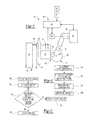
Figure 1 is a simplified schematic of a brake system. -
Figures 2 and 3 are flowcharts associated with a method of controlling a brake system. -
Figures 4-7 are exemplary plots that help illustrate method steps. - As required, detailed embodiments of the present invention are disclosed herein; however, it is to be understood that the disclosed embodiments are merely exemplary of the invention that may be embodied in various and alternative forms. The figures are not necessarily to scale; some features may be exaggerated or minimized to show details of particular components. Therefore, specific structural and functional details disclosed herein are not to be interpreted as limiting, but merely as a representative basis for teaching one skilled in the art to variously employ the present invention.
- Referring to
Figure 1 , anexemplary brake system 10 is shown. Thebrake system 10 may be provided with a vehicle, such as a motor vehicle like a truck, farm equipment, or military transport or weaponry vehicle. The vehicle may include a trailer for transporting cargo in one or more embodiments. - The
brake system 10 may be configured to slow or inhibit rotation of at least one associated wheel assembly. Thebrake system 10 may include a set offriction brakes 12, anactuator subsystem 14, and acontrol system 16. - A
friction brake 12, which may also be called a foundation brake, may be disposed proximate a wheel assembly and may be configured to slow rotation of the wheel assembly.Multiple friction brakes 12 may be provided with the vehicle and may be controlled by thecontrol system 16. Thefriction brake 12 may have any suitable configuration. For example, afriction brake 12 may be configured as a disc brake. Thefriction brake 12 may include abrake friction member 20 and at least onebrake pad assembly 22. - The
brake friction member 20 may be connected to a wheel hub. As such, thebrake friction member 20 may rotate with a wheel assembly and with respect to abrake pad assembly 22 when braking is not requested. In a disc brake configuration, thebrake friction member 20 may be configured as a rotor, which is also known as a brake disc. - In a disc brake configuration, the
brake friction member 20 may extend into an opening in a carrier (not shown). The carrier may be fixedly mounted to the vehicle and may receive and/or support inboard and outboardbrake pad assemblies 22. As such, the carrier may straddle thebrake friction member 20 and help position the brake pad assemblies 22 on opposite sides of thebrake friction member 20. - The
brake pad assembly 22 may engage thebrake friction member 20 when braking is requested or commanded and exert frictional force against thebrake friction member 20 to retard or slow rotation of an associated wheel assembly. In a disc brake configuration, inboard and outboardbrake pad assemblies 22 may be disposed on opposite sides of thebrake friction member 20 and may be configured to engage opposite sides of thebrake friction member 20 to slow the rotation of a vehicle wheel. Thebrake pad assemblies 22 may be received in a caliper housing (not shown) that may be movably disposed on the carrier. More specifically, the caliper housing may be slidably disposed on a pair of slide pins that may be fixedly disposed on the carrier. The caliper housing may receive at least a portion of theactuator subsystem 14, which may actuate the brake pad assemblies 22 into engagement with thebrake friction member 20. For example, theactuator subsystem 14 may include one or more pistons that may actuate the inboardbrake pad assembly 22 toward thebrake friction member 20 and move the caliper housing to actuate the outboardbrake pad assembly 22 toward the rotor as will be discussed in more detail below. - The
brake pad assembly 22 may include abacking plate 30 and afriction material 32. - The
backing plate 30 may be a structural member of abrake pad assembly 22. Thebacking plate 30 may be made of any suitable material, such as a metal or metal alloy. - The
friction material 32, which may also be called a brake lining, may be disposed on thebacking plate 30. Thefriction material 32 may face toward thebrake friction member 20 and may engage thebrake friction member 20 during vehicle braking. In addition, thefriction material 32 may be spaced apart from and may not engage thebrake friction member 20 when thefriction brake 12 is not being applied. The clearance or distance between thefriction material 32 and thebrake friction member 20 when thefriction brake 12 is not being applied may be referred to as anair gap 34 or running clearance. No clearance or zero clearance may be present between thefriction material 32 and thebrake friction member 20 when thefriction brake 12 is applied. - The
actuator subsystem 14 may be configured to actuate abrake pad assembly 22 between a retracted position and an extended position. The retracted position may also be referred to as an initial position or rest position. Thebrake pad assembly 22 may be spaced apart from thebrake friction member 20 and may be stationary when in the retracted position. As such, abrake pad assembly 22 may be in the retracted position when thefriction brake 12 is not being applied. Thebrake pad assembly 22 and more specifically thefriction material 32 may engage thebrake friction member 20 when in the extended position. - The
actuator subsystem 14 may be disposed proximate or provided with the caliper housing. Theactuator subsystem 14 may have any suitable configuration. For example, theactuator subsystem 14 may have a pneumatic, hydraulic, electrical, or electromechanical configuration, or combinations thereof as are known by those skilled in the art. In the simplified schematic shown inFigure 1 , theactuator subsystem 14 has a pneumatic configuration. In such a configuration, theactuator subsystem 14 may include anactuator 40, anactuation mechanism 42, and an airgap adjustment mechanism 44. - The
actuator 40 may be configured to exert force that may be amplified and transmitted to actuate abrake pad assembly 22 toward thebrake friction member 20. Theactuator 40 may have any suitable configuration. For example, theactuator 40 may be a linear actuator, such as a pneumatic air chamber or pneumatic cylinder in one or more embodiments. In at least one embodiment, theactuator 40 may include anactuator rod 50 that may move linearly between a first position (return position) and a second position (advanced position). Theactuator 40 may be controlled by thecontrol system 16 and may actuate abrake pad assembly 22 in response to a brake command as will be discussed in more detail below. - The
actuation mechanism 42 may transmit force exerted by theactuator 40 to thebrake pad assemblies 22. For example, theactuator mechanism 42 may include various mechanical components, such as linkages, shafts, bearings, rollers, springs, and one or more pistons that may cooperate to transmit force to actuate thebrake pad assemblies 22 between the retracted and extended positions in a manner known by those skilled in the art. For illustration purposes, a simplified example of anactuation mechanism 42 is shown inFigure 1 that includes an operatingshaft 60, alinkage 62, aroller 64, and anactuator unit 66. - The
actuator 40 may be operatively connected to an operatingshaft 60. InFigure 1 , theactuator 40 is indirectly connected to the operatingshaft 60 via thelinkage 62, which may also be called an operating lever. Thelinkage 62 may be coupled to theactuator rod 50. As such, extending theactuator rod 50 may cause the operatingshaft 60 to rotate about anaxis 68 due to interaction with aroller 64. Theroller 64 may transmit force to thebrake pad assemblies 22 via theactuator unit 66, which may include more pistons in a manner known by those skilled in the art. - Movement of the actuator 40 from the first position to the second position may cause the
actuator rod 50 to move left from the position shown inFigure 1 . Movement of theactuator rod 50 may transmit force to the operatingshaft 60 via thelinkage 62 and may cause the operatingshaft 60 to rotate counterclockwise about theaxis 68 and/orroller 64 from the perspective shown. Force may then be transmitted to actuate abrake pad assembly 22 from the retracted position to the extended position by theactuator unit 66. In a floating caliper configuration, an inboardbrake pad assembly 22 may engage thebrake friction member 20 before and outboardbrake pad assembly 22. A reaction force may be transmitted to the outboardbrake pad assembly 22 to pull the outboardbrake pad assembly 22 against thebrake friction member 20 via movement of the floating caliper housing when the inboardbrake pad assembly 22 has engaged thebrake friction member 20. As such, the inboard and outboardbrake pad assemblies 22 may cooperate to engage and brake or inhibit rotation of thebrake friction member 20. The actuation mechanism components may return to their initial positions, or starting positions when a brake command ends and theactuator 40 is permitted to move from the second position to the first position (e.g., theactuator rod 50 is permitted to back to its initial position). As such, the operatingshaft 60 may rotate in a first direction when a brake pedal is actuated and may rotate in a second direction disposed opposite the first direction when the brake pedal is released. - The air
gap adjustment mechanism 44 may be provided to adjust the air gap to compensate for friction material wear or air gap or clearance changes that may be due to temperature change or other factors. In at least one embodiment, the airgap adjustment mechanism 44 may include anadjustment motor 70. Theadjustment motor 70 may have any suitable configuration. For example, theadjustment motor 70 may be an electric motor and may include an encoder that may be configured to measure displacement or rotation of a motor shaft to facilitate monitoring and control of theadjustment motor 70. Theadjustment motor 70 may be connected to components that may establish or set the retracted position or rest position of abrake pad assembly 22. For example, theadjustment motor 70 may be operatively connected to a tappet that may be provided with or associated with theactuator unit 66. In at least one embodiment, the tappet may receive the piston of theactuator unit 66 and may have threads that interact with corresponding threads on the piston to permit or inhibit relative rotation to adjust the air gap in a manner known by those skilled the art. Operation of theadjustment motor 70 may be controlled by thecontrol system 16. - The
control system 16 may be configured to monitor and/or control operation of thebrake system 10. Thecontrol system 16 may include one or more control modules orcontrollers 80 that may be provided to monitor and control various components. For simplicity, a single controller is shown inFigure 1 ; however, it is contemplated that multiple control modules or controllers or a distributed control architecture may be provided. Thecontroller 80 may monitor and control theactuator subsystem 14, airgap adjustment mechanism 44 and itsadjustment motor 70, and the amount of brake torque provided by thefriction brakes 12. In addition, thecontroller 80 may also process input signals or data from various input devices or sensors such as abrake pedal sensor 82 and an actuationmechanism position sensor 84. - A
brake pedal sensor 82 may be provided to detect a braking command or a brake torque command that may be provided by a vehicle driver or vehicle operator. For example, thebrake pedal sensor 82 may detect the position of abrake pedal 90 or the position or operating state of a component that may be connected to or operated by a brake pedal, such as a treadle valve that may modulate a control fluid pressure that may be provided to a relay valve that may control the supply of fluid to one ormore friction brakes 12 or friction brake actuators. Alternatively, thebrake pedal sensor 82 may be configured as a pressure sensor that may detect fluid pressure that may directly or indirectly control theactuator 40 or braking of the vehicle. The detected position of the brake pedal and/or detected pressure may be used to control the brake torque provided by thebrake system 10. For example, depending on the configuration of thebrake system 10 thecontroller 80 may control operation of a valve that controls fluid pressure provided to afriction brake 12, a brake pump that pressurizes fluid, and/or an electric motor that may actuate abrake pad assembly 22. The amount of brake torque provided by thebrake system 10 may be proportional to a detected angle of motion or amount of actuation of thebrake pedal 90 or other brake torque command input device. - The actuation
mechanism position sensor 84, which is also referred to as a position sensor, may detect rotation of the operatingshaft 60. As such, the actuationmechanism position sensor 84 may provide a signal or data that may be indicative of rotation of the operatingshaft 60 about theaxis 68. Operating shaft rotation may indirectly detect or provide data indicative of the width or size of theair gap 34 or distance of brake pad assembly travel between the retracted position and extended position. The actuationmechanism position sensor 84 may be of any suitable type. For example, the actuationmechanism position sensor 84 may be an encoder. - Referring to
Figures 2 and 3 , flowcharts illustrating a method of controlling thebrake system 10 are shown. As will be appreciated by one of ordinary skill in the art, the flowchart may represent control logic which may be implemented or affected in hardware, software, or a combination of hardware and software. For example, the various functions may be affected by a programmed microprocessor. The control logic may be implemented using any of a number of known programming and processing techniques or strategies and is not limited to the order or sequence illustrated. For instance, interrupt or event-driven processing may be employed in real-time control applications rather than a purely sequential strategy as illustrated. Likewise, parallel processing, multitasking, or multi-threaded systems and methods may be used. - Control logic may be independent of the particular programming language, operating system, processor, or circuitry used to develop and/or implement the control logic illustrated. Likewise, depending upon the particular programming language and processing strategy, various functions may be performed in the sequence illustrated, at substantially the same time, or in a different sequence while accomplishing the method of control. The illustrated functions may be modified, or in some cases omitted, without departing from the scope of the present invention. In at least one embodiment, a method may be executed by the
controller 80 and may be implemented as a closed loop control system. - As an overview, the method may indirectly estimate the size or width of the
air gap 34 between thebrake friction member 20 and abrake pad assembly 22 and may control or adjust the air gap as appropriate. The width of theair gap 34 may not be directly detected by a sensor or other device that may directly measure the distance from thebrake friction member 20 and abrake pad assembly 22 when thebrake pad assembly 22 is in the retracted position. Indirect estimation of the air gap may be affected by various factors that may lead to inaccurate air gap estimates. For example, indirect estimation of the air gap may be affected by multiple factors associated with the characteristics of the actuator subsystem 14 (wear, component expansion, component contraction, tolerance variations, vibrations, noise, position sensor bias and drift, etc.), which may be further affected by environmental factors (e.g., temperature which may cause component expansion or contraction, contaminants, etc.). Moreover, noise and disturbance during air gap detection, nonlinearity of the position sensor signal, and time delay in air gap adjustment may also influence air gap estimates. The method discussed below may help provide more accurate air gap estimates and control of the air gap. - Referring to
Figure 2 , a flowchart that overviews the method is shown. - At
block 100, the method may cycle the friction brake and obtain data or a signal from the actuationmechanism position sensor 84. The friction brake may be cycled when vehicle braking is desired or requested. A request for braking may be based on data or a signal from thebrake pedal sensor 82. A request for braking may also be automatically initiated or automatically requested rather than manually requested. For example, braking of the vehicle may be automatically initiated by an adaptive cruise control system or pre-impact collision avoidance system. An adaptive cruise control system may automatically adjust vehicle speed in response to the proximity and/or relative speed of another vehicle. As such, an adaptive cruise control system may brake the vehicle to adjust proximity and/or vehicle speed. A pre-impact collision avoidance system may be configured to detect a potential collision or impact with the vehicle before it occurs and brake or slow the vehicle to avoid a collision. Cycling the friction brake may include actuating one or morebrake pad assemblies 22 from the retracted position to the extended position (i.e., into engagement with the brake friction member 20) and releasing thebrake pad assembly 22 such that thebrake pad assembly 22 disengages thebrake friction member 20 and moves back to or toward the retracted position. The actuationmechanism position sensor 84 may detect rotation of the operatingshaft 60 during cycling of thefriction brake 12. As such, a signal or data from the actuationmechanism position sensor 84 may detect movement or the absence of movement of abrake pad assembly 22. An example of an exemplary signal from the actuationmechanism position sensor 84 is shown inFigure 4 and will be discussed in more detail below with the flowchart inFigure 3 . - At
block 102, the air gap (i.e., air gap size or width) may be estimated. The size or width of theair gap 34 may be estimated based on the signal or data from the actuationmechanism position sensor 84. The estimated size or width of theair gap 34 may be referred to as the estimated air gap. - At
block 104, the estimated air gap is compared to a desired air gap, which may also be referred to as a threshold air gap. The estimated air gap may be based on the signal from the actuationmechanism position sensor 84 as previously discussed. The desired air gap may be a predetermined value and may be based on the configuration of the brake system and/or vehicle development testing. The desired air gap may be indicative of an air gap width or distance beyond which thebrake pad assembly 22 and itsfriction material 32 is not sufficiently close to thebrake friction member 20 when in the retracted position. In addition, the desired air gap may be indicative of an air gap width or distance at which thebrake pad assembly 22 and itsfriction material 32 is too close to thebrake friction member 20 when in the retracted position. The desired air gap may be expressed as a single value but may incorporate a tolerance range. For example, the desired air gap may be expressed as a value like 0.6 mm, but may have a tolerance of +/- 0.05 mm, which thereby expresses the desired air gap as a range from 0.55 mm to 0.65 mm. Thus, the desired air gap may be a range rather than a single absolute value. If the estimated air gap is sufficiently close to the desired air gap, then the method may continue atblock 106. If the estimated air gap is not sufficiently close to the desired air gap, then the method may continue atblock 108. - At
block 106, the air gap may not be adjusted. The air gap may not be adjusted since the estimated air gap indicates that thefriction material 32 of at least onebrake pad assembly 22 is sufficiently close to thebrake friction member 20 when in the retracted position to provide a desired braking performance. Likewise, the air gap may not be adjusted when the estimated air gap indicates that thefriction material 32 of at least onebrake pad assembly 22 is sufficiently distant or not too close to thebrake friction member 20 when in the retracted position. As such, the retracted position may not be adjusted. - At
block 108, the air gap may be adjusted. For example, the air gap may be reduced by operating the airgap adjustment mechanism 44 to move one or morebrake pad assemblies 22 closer to thebrake friction member 20 when the estimated air gap is greater than the desired air gap. As such, the retracted position of abrake pad assembly 22 may be changed such that thebrake pad assembly 22 is moved closer to thebrake friction member 20 than the previous retracted position or before making the air gap adjustment. Similarly, the air gap may be increased by operating the airgap adjustment mechanism 44 to move one or morebrake pad assemblies 22 further from thebrake friction member 20 when the estimated air gap is less than the desired air gap. As such, the retracted position of abrake pad assembly 22 may be changed such that thebrake pad assembly 22 is moved further from thebrake friction member 20 than the previous retracted position or before making the air gap adjustment. In at least one embodiment, the air gap adjustment may be initiated or may occur during release of thebrake pad assembly 22, or while thebrake pad assembly 22 is moving from the extended position toward the retracted position. Theair gap 34 may be adjusted by operating theadjustment motor 70 to actuate the airgap adjustment mechanism 44 and set the retracted position closer to thebrake friction member 20. The amount of adjustment may be based on the difference between the estimated air gap and the desired air gap. The magnitude of the difference may then be used to determine a number of adjustment motor revolutions or length of time to activate theadjustment motor 70 to reduce the air gap to a desired amount or distance. For example, the distance or amount of brake pad movement per revolution of theadjustment motor 70 may be calculated or may be a predetermined amount that in turn may be used to determine how long to activate theadjustment motor 70 or how many motor shaft revolutions may be sufficient to reduce the air gap. - Referring to
Figure 3 , a flowchart is shown that provides more detail regarding estimation of the air gap. The flowchart inFigure 3 is best understood with reference toFigures 4-7 . InFigures 4-7 , the rotational position of the operatingshaft 60 detected by the actuationmechanism position sensor 84 is plotted on the vertical axis. The vertical axis may be depicted in any suitable units that may represent angular motion, such as degrees. InFigures 4-7 , units of measurement employed by the actuation mechanism position sensor 84 (e.g., encoder units) are used to represent a generic unit of measure and are referenced by the letter U. Time (t) is measured along the horizontal axis.Figures 5-7 show the signal from the position sensor during and after processing. - Referring to
Figure 4 , a signal from the actuationmechanism position sensor 84 before processing. Fromtime 0 to time 1, the operating shaft may not rotate. Thus, the actuationmechanism position sensor 84 may not detect rotation of the operating shaft during this time period. As such, the signal may be expected to extend along the time axis (i.e., the actuationmechanism position sensor 84 may be expected to have a reading of zero); however, the signal is shown with a negative signal drift from the time axis (i.e., the entire signal is offset downward or negatively from the expected position) which may result from one or more of the factors previously discussed. Cycling of the friction brake is shown between time 1 (t1) and time 4 (t4). The signal may increase from time 1 (t1) to time 2 (t2) at a first slope or with a first curvature, which may be indicative of actuation of one or more brake pad assemblies toward the brake friction member. From time 2 (t2) to time 3 (t3), the brake pad assembly may be in engagement with the brake friction member such that there is no air gap. As such, it would be expected that the signal would not change (i.e., the signal would be horizontal and constant); however, the signal is shown with a second slope or second curvature which may result from signal error and/or one or more of the mechanical and/or environmental factors previously discussed. The signal may decrease from time 3 (t3) to time 4 (t4) at a third slope or with a third curvature, which may be indicative of disengagement of one or more brake pad assemblies toward the brake friction member. After time 4 (t4), the actuationmechanism position sensor 84 does not detect rotation of the operating shaft. - At
block 200, the method determines inflection points associated with the signal. The inflection points may be determined by interpolation or any suitable signal processing technique. A first inflection point I1 is located at time 2 (t2). The first inflection point I1 may be indicative of engagement of the brake pad assembly with the brake friction member. A second inflection point I2 is located at time 3 (t3). The second inflection point I2 may be indicative of release of the brake pad assemblies or disengagement of the brake pad assemblies from the brake friction member. The first inflection point I1 may or may not have the same magnitude as the second inflection point I2. - At
block 202, the position sensor signal may be clipped. Clipping the signal from a position sensor may be based on the first and second inflection points. More specifically, the signal may be clipped to the time value that corresponds with the first inflection point I1 and may be clipped to the time value that corresponds with the second inflection point I2. This is best shown inFigure 5 . InFigure 5 , the signal is clipped such that the signal is a vertical line at time 2 (t2) from the horizontal line (originally shown fromtime 0 to time 1) to the first inflection point I1. Similarly, the signal is clipped such that the signal is a vertical line at time 3 (t3) from the second inflection point I2 to the horizontal line. - At
block 204, the method may perform drift compensation. Drift compensation may occur after clipping the signal atblock 202. Drift compensation may compensate or correct for the drift or non-zero signal that would otherwise be expected when the friction brake is not actuated or cycled. Drift compensation is best understood by comparingFigure 5 to Figure 6 . InFigure 6 , the entire clipped signal inFigure 5 is adjusted such that the encoder measurement is set to zero when the friction brake is not actuated. As such, the entire position sensor signal may be adjusted upward (when there is negative signal drift) or downward (if there is positive signal drift) so that the signal is set to zero before the first inflection point I1 and/or after the second inflection point I2. The amount of signal drift shown inFigure 5 is designated D. Drift compensation may be based on a drift measurement. Drift measurement may be based on an actual or physical measurement. For example, drift compensation may be based on drift measurement data from an absolute position sensor that may directly detecting or measure the width of the air gap. Alternatively, drift compensation may be based on an estimated drift measurement provided by a model-based system in which brake pressure and or brake temperature may be used to model or determine an estimated drift amount. - At
block 206, error adjustment may occur. Error adjustment may adjust the signal to a constant value between the first inflection point I1 and the second inflection point I2. Such adjustments may be based on a reasoning process that may employ fuzzy logic. Error adjustment is best shown by comparingFigures 5 and 6 . InFigure 5 , the shaded area is the error area. The error area may represent a signal region where a stable constant (horizontal) signal is expected and may be bounded by the signal located between the first inflection point I1 and the second inflection point I2, or a straight line that may extend from I1 to I2. A centroid or geometrical center of the error area may be determined in any suitable manner, such as by integration of the signal curve between and above I1 and I2 in the example shown inFigure 5 . The centroid may be similar to a "center of mass" of the error area. The centroid may include a time axis coordinate and an encoder axis coordinate. InFigure 5 , the centroid is represented by the letter C and has an encoder axis (vertical axis) coordinate of yc. Encoder axis centroid and more particularly the encoder axis coordinate may be used to level the signal. InFigure 7 , the signal is adjusted such that the signal is set to a constant value that corresponds to yc between time 2 (t2) and time 3 (t3) (e.g., between I1 and I2). After time 3 (t3) coordinate yc may be stored or maintained until the next brake action. - The air gap may now be estimated based on the processed signal. More specifically, the air gap may be represented by vertical axis distance to the constant signal between I1 and I2 that corresponds to yc. If desired, this value may be converted from encoder units to other units, such as millimeters by calculation or a lookup table. For example, a single encoder unit may correspond with a predetermined linear actuation distance of a brake pad assembly. Such a relationship or ratio may be based on the configuration of the brake system and/or vehicle development testing.
- While exemplary embodiments are described above, it is not intended that these embodiments describe all possible forms of the invention. Rather, the words used in the specification are words of description rather than limitation, and it is understood that various changes may be made without departing from the spirit and scope of the invention. Additionally, the features of various implementing embodiments may be combined to form further embodiments of the invention.
Claims (15)
- A method of controlling a brake system comprising:cycling a friction brake;indirectly estimating an air gap between a brake friction member and a brake pad assembly based on a signal from a position sensor that detects cycling of the friction brake; andadjusting the air gap when an estimated air gap exceeds a desired air gap.
- The method of claim 1 wherein the position sensor detects rotation of an operating shaft during cycling of the friction brake and the signal from the position sensor is indicative of actuation of a brake pedal.
- The method of claim 1 wherein cycling the friction brake further comprises actuating the brake pad assembly from a retracted position in which the brake pad assembly is spaced apart from the brake friction member into engagement with the brake friction member and releasing the brake pad assembly such that the brake pad assembly disengages the brake friction member and moves toward the retracted position.
- The method of claim 3 wherein adjusting the air gap further comprises operating an adjustment motor to change the retracted position such that the brake pad assembly is disposed closer to the brake friction member.
- The method of claim 3 further comprising adjusting the air gap when an estimated air gap is less than the desired air gap by operating an adjustment motor to change the retracted position such that the brake pad assembly is disposed further from the brake friction member.
- The method of claim 3 wherein adjusting the air gap occurs during release of the brake pad assembly.
- The method of claim 3 wherein indirectly estimating the air gap includes clipping the signal from the position sensor by determining a first inflection point and a second inflection point of the signal and clipping the signal to a first time value that corresponds to the first inflection point and to a second time value corresponds to the second inflection point.
- The method of claim 7 the first inflection point is indicative of engagement of the brake pad assembly with the brake friction member and the second inflection point is indicative of disengagement of the brake pad assembly from the brake friction member.
- The method of claim 7 wherein indirectly estimating the air gap further comprises adjusting the signal to compensate for drift after clipping the signal.
- The method of claim 9 wherein indirectly estimating the air gap further comprises making an error adjustment by determining a centroid of an error area disposed between the first inflection point and the second inflection point and adjusting the signal based on the centroid of the error area.
- The method of claim 10 wherein making the error adjustment includes adjusting the signal to a constant value between the first inflection point and the second inflection point, wherein making the error adjustment is based on fuzzy logic.
- A brake system comprising:a brake friction member;a brake pad assembly configured to move between a retracted position in which the brake pad assembly does not engage the brake friction member and an extended position in which the brake pad assembly engages the brake friction member;an actuator subsystem that includes an operating shaft that rotates when the brake pad assembly moves between the retracted position and the extended position; anda position sensor that detects rotation of the operating shaft;wherein an air gap between the brake pad assembly and the brake friction member is estimated based on a signal from the position sensor.
- The brake system of claim 12 wherein the signal from the position sensor is obtained when the brake pad assembly moves from the retracted position to the extended position and back to the retracted position.
- The brake system of claim 12 further comprising an adjustment motor, wherein the adjustment motor moves the brake pad assembly closer to the brake friction member to reduce the air gap when an estimated air gap that is based on the signal from the position sensor exceeds a desired air gap and the adjustment motor moves the brake pad assembly further from the brake friction member to increase the air gap when an estimated air gap that is based on the signal from the position sensor does not exceed a desired air gap.
- The brake system of claim 12 wherein an adjustment motor adjusts the air gap when the brake pad assembly moves from the extended position toward the retracted position and wherein the adjustment motor does not move the brake pad assembly from the retracted position to the extended position.
Applications Claiming Priority (1)
| Application Number | Priority Date | Filing Date | Title |
|---|---|---|---|
| US14/212,602 US9457782B2 (en) | 2014-03-14 | 2014-03-14 | Brake system and method of control with air gap estimation |
Publications (3)
| Publication Number | Publication Date |
|---|---|
| EP2927068A2 true EP2927068A2 (en) | 2015-10-07 |
| EP2927068A3 EP2927068A3 (en) | 2016-02-24 |
| EP2927068B1 EP2927068B1 (en) | 2019-01-30 |
Family
ID=52477674
Family Applications (1)
| Application Number | Title | Priority Date | Filing Date |
|---|---|---|---|
| EP15155613.1A Active EP2927068B1 (en) | 2014-03-14 | 2015-02-18 | Brake system and method of control with air gap estimation |
Country Status (2)
| Country | Link |
|---|---|
| US (1) | US9457782B2 (en) |
| EP (1) | EP2927068B1 (en) |
Cited By (3)
| Publication number | Priority date | Publication date | Assignee | Title |
|---|---|---|---|---|
| WO2019068701A1 (en) * | 2017-10-05 | 2019-04-11 | Ve Vienna Engineering Forschungs- Und Entwicklungs Gmbh | Method and brake control for actuating a friction brake |
| WO2019076426A1 (en) * | 2017-10-16 | 2019-04-25 | Wabco Europe Bvba | Brake device, particularly a utility vehicle disk brake |
| WO2020143974A1 (en) * | 2019-01-07 | 2020-07-16 | Wabco Europe Bvba | Method for determining a clearance of an electromechanical brake, and brake in question and control unit |
Families Citing this family (6)
| Publication number | Priority date | Publication date | Assignee | Title |
|---|---|---|---|---|
| EP3251908B1 (en) | 2016-06-03 | 2021-01-20 | Meritor Heavy Vehicle Braking Systems (UK) Limited | Brake system and method of control with air gap estimation |
| DE102016223826A1 (en) * | 2016-11-30 | 2018-05-30 | Robert Bosch Gmbh | Method and device for operating a hydraulic brake system, brake system |
| CN108340895B (en) * | 2017-01-23 | 2020-05-08 | 长城汽车股份有限公司 | Control method and control system of electronic parking system and vehicle |
| US10933855B2 (en) | 2018-02-20 | 2021-03-02 | Robert Bosch Gmbh | Drift mode for electronic handbrake |
| DE102019100481A1 (en) * | 2019-01-10 | 2020-07-16 | Wabco Europe Bvba | Method for setting an air gap of an electromechanical brake and the relevant brake and control device |
| US11938911B2 (en) | 2021-04-08 | 2024-03-26 | Arvinmeritor Technology, Llc | Brake system and method of monitoring |
Citations (1)
| Publication number | Priority date | Publication date | Assignee | Title |
|---|---|---|---|---|
| US5432442A (en) | 1993-07-30 | 1995-07-11 | Itt Corporation | Speed sensor including output signal proportional to air gap size |
Family Cites Families (16)
| Publication number | Priority date | Publication date | Assignee | Title |
|---|---|---|---|---|
| DE4017950A1 (en) | 1990-06-05 | 1991-12-12 | Wabco Westinghouse Fahrzeug | Vehicle brake operating device - uses detected play for adjustment of brake operating shaft relative to brake lever |
| US5285190A (en) | 1991-11-04 | 1994-02-08 | Onboard Systems Limited | Automatic slack adjuster with operation and adjustment monitor |
| DE19536695A1 (en) | 1995-09-30 | 1997-04-03 | Teves Gmbh Alfred | System for controlling or regulating an electromechanical brake |
| GB9823199D0 (en) | 1998-10-24 | 1998-12-16 | Lucas Ind Plc | Vehicle brake having brake de-adjust |
| DE19730094A1 (en) | 1997-07-14 | 1999-01-21 | Itt Mfg Enterprises Inc | System for controlling or regulating an electromechanical brake |
| GB9823198D0 (en) | 1998-10-24 | 1998-12-16 | Lucas Ind Plc | Vehicle brake having electric motor control of brake running clearance |
| DE10138452B4 (en) | 2001-08-04 | 2014-07-17 | Wabco Gmbh | Method for Lüftspielnachstellung of disc brakes |
| DE10228115B4 (en) | 2002-06-24 | 2004-05-13 | Lucas Automotive Gmbh | Electrically actuated vehicle brake and method for controlling an electrically actuated vehicle brake |
| US7726748B2 (en) | 2005-09-26 | 2010-06-01 | Zumberge Jon T | Low force level detection system and method |
| US20070235267A1 (en) | 2006-04-11 | 2007-10-11 | Goodrich Corporation | Controller for electromechanical braking system with running clearance adjustment and method |
| DE102006029699B4 (en) | 2006-06-28 | 2009-09-03 | Lucas Automotive Gmbh | Method for determining the state of wear of brake linings on wheel brake units of a motor vehicle brake system and motor vehicle brake system |
| DE102007004604A1 (en) * | 2007-01-30 | 2008-07-31 | Siemens Ag | Electromechanical disc brake e.g. wedge brake, operational parameter e.g. lifting clearance, determining method for motor vehicle involves bringing brake lining into contact points with brake disk for detecting position of points |
| US8220594B2 (en) * | 2007-08-30 | 2012-07-17 | Nippon Soken, Inc | Electric brake device |
| JP5637067B2 (en) | 2011-05-24 | 2014-12-10 | 株式会社アドヴィックス | Electric brake device and control method of electric brake device |
| EP2650556B1 (en) | 2012-03-28 | 2019-10-23 | Meritor Heavy Vehicle Braking Systems (UK) Limited | Brake |
| AT512683A1 (en) | 2012-04-12 | 2013-10-15 | Ve Vienna Engineering Forschungs Und Entwicklungs Gmbh | Braking system and braking method for an electrically operated, non-linear friction brake |
-
2014
- 2014-03-14 US US14/212,602 patent/US9457782B2/en active Active
-
2015
- 2015-02-18 EP EP15155613.1A patent/EP2927068B1/en active Active
Patent Citations (1)
| Publication number | Priority date | Publication date | Assignee | Title |
|---|---|---|---|---|
| US5432442A (en) | 1993-07-30 | 1995-07-11 | Itt Corporation | Speed sensor including output signal proportional to air gap size |
Cited By (7)
| Publication number | Priority date | Publication date | Assignee | Title |
|---|---|---|---|---|
| WO2019068701A1 (en) * | 2017-10-05 | 2019-04-11 | Ve Vienna Engineering Forschungs- Und Entwicklungs Gmbh | Method and brake control for actuating a friction brake |
| CN111511612A (en) * | 2017-10-05 | 2020-08-07 | Ve维也纳工程研究和发展有限公司 | Method for actuating a friction brake and brake controller |
| US11623620B2 (en) | 2017-10-05 | 2023-04-11 | Ve Vienna Engineering Forschungs Und Entwicklungs Gmbh | Method and brake control for actuating a friction brake |
| WO2019076426A1 (en) * | 2017-10-16 | 2019-04-25 | Wabco Europe Bvba | Brake device, particularly a utility vehicle disk brake |
| US11125293B2 (en) | 2017-10-16 | 2021-09-21 | Wabco Europe Bvba | Brake device for a utility vehicle |
| WO2020143974A1 (en) * | 2019-01-07 | 2020-07-16 | Wabco Europe Bvba | Method for determining a clearance of an electromechanical brake, and brake in question and control unit |
| US11891033B2 (en) | 2019-01-07 | 2024-02-06 | Zf Cv Systems Europe Bv | Method for determining a clearance of an electromechanical brake, brake, and control unit |
Also Published As
| Publication number | Publication date |
|---|---|
| US9457782B2 (en) | 2016-10-04 |
| EP2927068A3 (en) | 2016-02-24 |
| US20150260246A1 (en) | 2015-09-17 |
| EP2927068B1 (en) | 2019-01-30 |
Similar Documents
| Publication | Publication Date | Title |
|---|---|---|
| EP2927068B1 (en) | Brake system and method of control with air gap estimation | |
| US10422396B2 (en) | Brake system and method of control with air gap estimation | |
| US9518625B2 (en) | Method for actuating an electrically actuated friction brake | |
| EP3032131B1 (en) | Brake assembly and method of control | |
| US8336969B2 (en) | Brake apparatus | |
| CN111511612B (en) | Method for actuating a friction brake and brake control | |
| US8676409B2 (en) | Electric brake apparatus | |
| US20120193177A1 (en) | Electric brake apparatus | |
| US10800393B2 (en) | Method and device for monitoring the condition of a service brake, as well as brake and brake system | |
| JP2000033863A (en) | Method for controlling vehicle brake and apparatus for same | |
| EP2799297A1 (en) | Brake control apparatus for vehicle | |
| CN105190077A (en) | Disk brake having a clearance-monitoring device, and method for monitoring clearance | |
| US9321437B2 (en) | Motor control system and method for wear compensation of electromechanical brake | |
| US11639159B2 (en) | Method and device for operating an automated parking brake | |
| US20220032885A1 (en) | Electric brake, and control device | |
| JP5746319B2 (en) | Automated clutch control method | |
| CN113015862A (en) | Electric brake and control device | |
| JP6906398B2 (en) | Electric brake device | |
| WO2023243266A1 (en) | Electric brake device | |
| KR101813965B1 (en) | Method for controlling distance between disk and pad in electro mechanical brake | |
| CN117681840A (en) | Method for operating an electromechanical service brake without force sensor and braking system | |
| EP2644929A1 (en) | Method of determining a zero instantaneous running clearance position of a brake | |
| KR20160049203A (en) | Device and method for controlling engine braking force |
Legal Events
| Date | Code | Title | Description |
|---|---|---|---|
| PUAI | Public reference made under article 153(3) epc to a published international application that has entered the european phase |
Free format text: ORIGINAL CODE: 0009012 |
|
| AK | Designated contracting states |
Kind code of ref document: A2 Designated state(s): AL AT BE BG CH CY CZ DE DK EE ES FI FR GB GR HR HU IE IS IT LI LT LU LV MC MK MT NL NO PL PT RO RS SE SI SK SM TR |
|
| AX | Request for extension of the european patent |
Extension state: BA ME |
|
| PUAL | Search report despatched |
Free format text: ORIGINAL CODE: 0009013 |
|
| AK | Designated contracting states |
Kind code of ref document: A3 Designated state(s): AL AT BE BG CH CY CZ DE DK EE ES FI FR GB GR HR HU IE IS IT LI LT LU LV MC MK MT NL NO PL PT RO RS SE SI SK SM TR |
|
| AX | Request for extension of the european patent |
Extension state: BA ME |
|
| RIC1 | Information provided on ipc code assigned before grant |
Ipc: F16D 65/16 20060101ALI20160118BHEP Ipc: B60T 17/22 20060101ALI20160118BHEP Ipc: B60T 13/74 20060101AFI20160118BHEP Ipc: F16D 65/56 20060101ALI20160118BHEP |
|
| 17P | Request for examination filed |
Effective date: 20160801 |
|
| RBV | Designated contracting states (corrected) |
Designated state(s): AL AT BE BG CH CY CZ DE DK EE ES FI FR GB GR HR HU IE IS IT LI LT LU LV MC MK MT NL NO PL PT RO RS SE SI SK SM TR |
|
| GRAP | Despatch of communication of intention to grant a patent |
Free format text: ORIGINAL CODE: EPIDOSNIGR1 |
|
| STAA | Information on the status of an ep patent application or granted ep patent |
Free format text: STATUS: GRANT OF PATENT IS INTENDED |
|
| INTG | Intention to grant announced |
Effective date: 20180730 |
|
| GRAS | Grant fee paid |
Free format text: ORIGINAL CODE: EPIDOSNIGR3 |
|
| GRAJ | Information related to disapproval of communication of intention to grant by the applicant or resumption of examination proceedings by the epo deleted |
Free format text: ORIGINAL CODE: EPIDOSDIGR1 |
|
| GRAL | Information related to payment of fee for publishing/printing deleted |
Free format text: ORIGINAL CODE: EPIDOSDIGR3 |
|
| STAA | Information on the status of an ep patent application or granted ep patent |
Free format text: STATUS: REQUEST FOR EXAMINATION WAS MADE |
|
| GRAR | Information related to intention to grant a patent recorded |
Free format text: ORIGINAL CODE: EPIDOSNIGR71 |
|
| STAA | Information on the status of an ep patent application or granted ep patent |
Free format text: STATUS: GRANT OF PATENT IS INTENDED |
|
| GRAA | (expected) grant |
Free format text: ORIGINAL CODE: 0009210 |
|
| STAA | Information on the status of an ep patent application or granted ep patent |
Free format text: STATUS: THE PATENT HAS BEEN GRANTED |
|
| INTC | Intention to grant announced (deleted) | ||
| INTG | Intention to grant announced |
Effective date: 20181213 |
|
| AK | Designated contracting states |
Kind code of ref document: B1 Designated state(s): AL AT BE BG CH CY CZ DE DK EE ES FI FR GB GR HR HU IE IS IT LI LT LU LV MC MK MT NL NO PL PT RO RS SE SI SK SM TR |
|
| REG | Reference to a national code |
Ref country code: GB Ref legal event code: FG4D |
|
| REG | Reference to a national code |
Ref country code: CH Ref legal event code: EP |
|
| REG | Reference to a national code |
Ref country code: AT Ref legal event code: REF Ref document number: 1093009 Country of ref document: AT Kind code of ref document: T Effective date: 20190215 |
|
| REG | Reference to a national code |
Ref country code: IE Ref legal event code: FG4D |
|
| REG | Reference to a national code |
Ref country code: DE Ref legal event code: R096 Ref document number: 602015023857 Country of ref document: DE |
|
| REG | Reference to a national code |
Ref country code: SE Ref legal event code: TRGR |
|
| REG | Reference to a national code |
Ref country code: LT Ref legal event code: MG4D |
|
| REG | Reference to a national code |
Ref country code: NL Ref legal event code: MP Effective date: 20190130 |
|
| PG25 | Lapsed in a contracting state [announced via postgrant information from national office to epo] |
Ref country code: LT Free format text: LAPSE BECAUSE OF FAILURE TO SUBMIT A TRANSLATION OF THE DESCRIPTION OR TO PAY THE FEE WITHIN THE PRESCRIBED TIME-LIMIT Effective date: 20190130 Ref country code: FI Free format text: LAPSE BECAUSE OF FAILURE TO SUBMIT A TRANSLATION OF THE DESCRIPTION OR TO PAY THE FEE WITHIN THE PRESCRIBED TIME-LIMIT Effective date: 20190130 Ref country code: NO Free format text: LAPSE BECAUSE OF FAILURE TO SUBMIT A TRANSLATION OF THE DESCRIPTION OR TO PAY THE FEE WITHIN THE PRESCRIBED TIME-LIMIT Effective date: 20190430 Ref country code: NL Free format text: LAPSE BECAUSE OF FAILURE TO SUBMIT A TRANSLATION OF THE DESCRIPTION OR TO PAY THE FEE WITHIN THE PRESCRIBED TIME-LIMIT Effective date: 20190130 Ref country code: ES Free format text: LAPSE BECAUSE OF FAILURE TO SUBMIT A TRANSLATION OF THE DESCRIPTION OR TO PAY THE FEE WITHIN THE PRESCRIBED TIME-LIMIT Effective date: 20190130 Ref country code: PL Free format text: LAPSE BECAUSE OF FAILURE TO SUBMIT A TRANSLATION OF THE DESCRIPTION OR TO PAY THE FEE WITHIN THE PRESCRIBED TIME-LIMIT Effective date: 20190130 Ref country code: PT Free format text: LAPSE BECAUSE OF FAILURE TO SUBMIT A TRANSLATION OF THE DESCRIPTION OR TO PAY THE FEE WITHIN THE PRESCRIBED TIME-LIMIT Effective date: 20190530 |
|
| REG | Reference to a national code |
Ref country code: AT Ref legal event code: MK05 Ref document number: 1093009 Country of ref document: AT Kind code of ref document: T Effective date: 20190130 |
|
| PG25 | Lapsed in a contracting state [announced via postgrant information from national office to epo] |
Ref country code: LV Free format text: LAPSE BECAUSE OF FAILURE TO SUBMIT A TRANSLATION OF THE DESCRIPTION OR TO PAY THE FEE WITHIN THE PRESCRIBED TIME-LIMIT Effective date: 20190130 Ref country code: RS Free format text: LAPSE BECAUSE OF FAILURE TO SUBMIT A TRANSLATION OF THE DESCRIPTION OR TO PAY THE FEE WITHIN THE PRESCRIBED TIME-LIMIT Effective date: 20190130 Ref country code: BG Free format text: LAPSE BECAUSE OF FAILURE TO SUBMIT A TRANSLATION OF THE DESCRIPTION OR TO PAY THE FEE WITHIN THE PRESCRIBED TIME-LIMIT Effective date: 20190430 Ref country code: IS Free format text: LAPSE BECAUSE OF FAILURE TO SUBMIT A TRANSLATION OF THE DESCRIPTION OR TO PAY THE FEE WITHIN THE PRESCRIBED TIME-LIMIT Effective date: 20190530 Ref country code: HR Free format text: LAPSE BECAUSE OF FAILURE TO SUBMIT A TRANSLATION OF THE DESCRIPTION OR TO PAY THE FEE WITHIN THE PRESCRIBED TIME-LIMIT Effective date: 20190130 Ref country code: GR Free format text: LAPSE BECAUSE OF FAILURE TO SUBMIT A TRANSLATION OF THE DESCRIPTION OR TO PAY THE FEE WITHIN THE PRESCRIBED TIME-LIMIT Effective date: 20190501 |
|
| REG | Reference to a national code |
Ref country code: CH Ref legal event code: PL |
|
| PG25 | Lapsed in a contracting state [announced via postgrant information from national office to epo] |
Ref country code: DK Free format text: LAPSE BECAUSE OF FAILURE TO SUBMIT A TRANSLATION OF THE DESCRIPTION OR TO PAY THE FEE WITHIN THE PRESCRIBED TIME-LIMIT Effective date: 20190130 Ref country code: AL Free format text: LAPSE BECAUSE OF FAILURE TO SUBMIT A TRANSLATION OF THE DESCRIPTION OR TO PAY THE FEE WITHIN THE PRESCRIBED TIME-LIMIT Effective date: 20190130 Ref country code: MC Free format text: LAPSE BECAUSE OF FAILURE TO SUBMIT A TRANSLATION OF THE DESCRIPTION OR TO PAY THE FEE WITHIN THE PRESCRIBED TIME-LIMIT Effective date: 20190130 Ref country code: SK Free format text: LAPSE BECAUSE OF FAILURE TO SUBMIT A TRANSLATION OF THE DESCRIPTION OR TO PAY THE FEE WITHIN THE PRESCRIBED TIME-LIMIT Effective date: 20190130 Ref country code: LU Free format text: LAPSE BECAUSE OF NON-PAYMENT OF DUE FEES Effective date: 20190218 Ref country code: IT Free format text: LAPSE BECAUSE OF FAILURE TO SUBMIT A TRANSLATION OF THE DESCRIPTION OR TO PAY THE FEE WITHIN THE PRESCRIBED TIME-LIMIT Effective date: 20190130 Ref country code: EE Free format text: LAPSE BECAUSE OF FAILURE TO SUBMIT A TRANSLATION OF THE DESCRIPTION OR TO PAY THE FEE WITHIN THE PRESCRIBED TIME-LIMIT Effective date: 20190130 Ref country code: CZ Free format text: LAPSE BECAUSE OF FAILURE TO SUBMIT A TRANSLATION OF THE DESCRIPTION OR TO PAY THE FEE WITHIN THE PRESCRIBED TIME-LIMIT Effective date: 20190130 Ref country code: RO Free format text: LAPSE BECAUSE OF FAILURE TO SUBMIT A TRANSLATION OF THE DESCRIPTION OR TO PAY THE FEE WITHIN THE PRESCRIBED TIME-LIMIT Effective date: 20190130 |
|
| REG | Reference to a national code |
Ref country code: DE Ref legal event code: R097 Ref document number: 602015023857 Country of ref document: DE |
|
| REG | Reference to a national code |
Ref country code: BE Ref legal event code: MM Effective date: 20190228 |
|
| REG | Reference to a national code |
Ref country code: IE Ref legal event code: MM4A |
|
| PG25 | Lapsed in a contracting state [announced via postgrant information from national office to epo] |
Ref country code: SM Free format text: LAPSE BECAUSE OF FAILURE TO SUBMIT A TRANSLATION OF THE DESCRIPTION OR TO PAY THE FEE WITHIN THE PRESCRIBED TIME-LIMIT Effective date: 20190130 |
|
| PLBE | No opposition filed within time limit |
Free format text: ORIGINAL CODE: 0009261 |
|
| STAA | Information on the status of an ep patent application or granted ep patent |
Free format text: STATUS: NO OPPOSITION FILED WITHIN TIME LIMIT |
|
| GBPC | Gb: european patent ceased through non-payment of renewal fee |
Effective date: 20190430 |
|
| PG25 | Lapsed in a contracting state [announced via postgrant information from national office to epo] |
Ref country code: AT Free format text: LAPSE BECAUSE OF FAILURE TO SUBMIT A TRANSLATION OF THE DESCRIPTION OR TO PAY THE FEE WITHIN THE PRESCRIBED TIME-LIMIT Effective date: 20190130 Ref country code: LI Free format text: LAPSE BECAUSE OF NON-PAYMENT OF DUE FEES Effective date: 20190228 Ref country code: CH Free format text: LAPSE BECAUSE OF NON-PAYMENT OF DUE FEES Effective date: 20190228 |
|
| 26N | No opposition filed |
Effective date: 20191031 |
|
| PG25 | Lapsed in a contracting state [announced via postgrant information from national office to epo] |
Ref country code: IE Free format text: LAPSE BECAUSE OF NON-PAYMENT OF DUE FEES Effective date: 20190218 Ref country code: GB Free format text: LAPSE BECAUSE OF NON-PAYMENT OF DUE FEES Effective date: 20190430 |
|
| PG25 | Lapsed in a contracting state [announced via postgrant information from national office to epo] |
Ref country code: BE Free format text: LAPSE BECAUSE OF NON-PAYMENT OF DUE FEES Effective date: 20190228 Ref country code: SI Free format text: LAPSE BECAUSE OF FAILURE TO SUBMIT A TRANSLATION OF THE DESCRIPTION OR TO PAY THE FEE WITHIN THE PRESCRIBED TIME-LIMIT Effective date: 20190130 |
|
| PG25 | Lapsed in a contracting state [announced via postgrant information from national office to epo] |
Ref country code: TR Free format text: LAPSE BECAUSE OF FAILURE TO SUBMIT A TRANSLATION OF THE DESCRIPTION OR TO PAY THE FEE WITHIN THE PRESCRIBED TIME-LIMIT Effective date: 20190130 |
|
| PG25 | Lapsed in a contracting state [announced via postgrant information from national office to epo] |
Ref country code: MT Free format text: LAPSE BECAUSE OF NON-PAYMENT OF DUE FEES Effective date: 20190218 |
|
| PG25 | Lapsed in a contracting state [announced via postgrant information from national office to epo] |
Ref country code: CY Free format text: LAPSE BECAUSE OF FAILURE TO SUBMIT A TRANSLATION OF THE DESCRIPTION OR TO PAY THE FEE WITHIN THE PRESCRIBED TIME-LIMIT Effective date: 20190130 |
|
| PG25 | Lapsed in a contracting state [announced via postgrant information from national office to epo] |
Ref country code: HU Free format text: LAPSE BECAUSE OF FAILURE TO SUBMIT A TRANSLATION OF THE DESCRIPTION OR TO PAY THE FEE WITHIN THE PRESCRIBED TIME-LIMIT; INVALID AB INITIO Effective date: 20150218 |
|
| PG25 | Lapsed in a contracting state [announced via postgrant information from national office to epo] |
Ref country code: MK Free format text: LAPSE BECAUSE OF FAILURE TO SUBMIT A TRANSLATION OF THE DESCRIPTION OR TO PAY THE FEE WITHIN THE PRESCRIBED TIME-LIMIT Effective date: 20190130 |
|
| PGFP | Annual fee paid to national office [announced via postgrant information from national office to epo] |
Ref country code: FR Payment date: 20230223 Year of fee payment: 9 |
|
| PGFP | Annual fee paid to national office [announced via postgrant information from national office to epo] |
Ref country code: SE Payment date: 20230227 Year of fee payment: 9 Ref country code: DE Payment date: 20230223 Year of fee payment: 9 |
|
| P01 | Opt-out of the competence of the unified patent court (upc) registered |
Effective date: 20230531 |