EP2921286A1 - Additive manufacturing machine - Google Patents
Additive manufacturing machine Download PDFInfo
- Publication number
- EP2921286A1 EP2921286A1 EP15159901.6A EP15159901A EP2921286A1 EP 2921286 A1 EP2921286 A1 EP 2921286A1 EP 15159901 A EP15159901 A EP 15159901A EP 2921286 A1 EP2921286 A1 EP 2921286A1
- Authority
- EP
- European Patent Office
- Prior art keywords
- cartridge
- powder
- additive manufacturing
- manufacturing machine
- powdered material
- Prior art date
- Legal status (The legal status is an assumption and is not a legal conclusion. Google has not performed a legal analysis and makes no representation as to the accuracy of the status listed.)
- Withdrawn
Links
Images


Classifications
-
- B—PERFORMING OPERATIONS; TRANSPORTING
- B29—WORKING OF PLASTICS; WORKING OF SUBSTANCES IN A PLASTIC STATE IN GENERAL
- B29C—SHAPING OR JOINING OF PLASTICS; SHAPING OF MATERIAL IN A PLASTIC STATE, NOT OTHERWISE PROVIDED FOR; AFTER-TREATMENT OF THE SHAPED PRODUCTS, e.g. REPAIRING
- B29C64/00—Additive manufacturing, i.e. manufacturing of three-dimensional [3D] objects by additive deposition, additive agglomeration or additive layering, e.g. by 3D printing, stereolithography or selective laser sintering
- B29C64/10—Processes of additive manufacturing
- B29C64/141—Processes of additive manufacturing using only solid materials
- B29C64/153—Processes of additive manufacturing using only solid materials using layers of powder being selectively joined, e.g. by selective laser sintering or melting
-
- B—PERFORMING OPERATIONS; TRANSPORTING
- B22—CASTING; POWDER METALLURGY
- B22F—WORKING METALLIC POWDER; MANUFACTURE OF ARTICLES FROM METALLIC POWDER; MAKING METALLIC POWDER; APPARATUS OR DEVICES SPECIALLY ADAPTED FOR METALLIC POWDER
- B22F10/00—Additive manufacturing of workpieces or articles from metallic powder
- B22F10/10—Formation of a green body
- B22F10/12—Formation of a green body by photopolymerisation, e.g. stereolithography [SLA] or digital light processing [DLP]
-
- B—PERFORMING OPERATIONS; TRANSPORTING
- B22—CASTING; POWDER METALLURGY
- B22F—WORKING METALLIC POWDER; MANUFACTURE OF ARTICLES FROM METALLIC POWDER; MAKING METALLIC POWDER; APPARATUS OR DEVICES SPECIALLY ADAPTED FOR METALLIC POWDER
- B22F12/00—Apparatus or devices specially adapted for additive manufacturing; Auxiliary means for additive manufacturing; Combinations of additive manufacturing apparatus or devices with other processing apparatus or devices
- B22F12/50—Means for feeding of material, e.g. heads
-
- B—PERFORMING OPERATIONS; TRANSPORTING
- B29—WORKING OF PLASTICS; WORKING OF SUBSTANCES IN A PLASTIC STATE IN GENERAL
- B29C—SHAPING OR JOINING OF PLASTICS; SHAPING OF MATERIAL IN A PLASTIC STATE, NOT OTHERWISE PROVIDED FOR; AFTER-TREATMENT OF THE SHAPED PRODUCTS, e.g. REPAIRING
- B29C64/00—Additive manufacturing, i.e. manufacturing of three-dimensional [3D] objects by additive deposition, additive agglomeration or additive layering, e.g. by 3D printing, stereolithography or selective laser sintering
- B29C64/20—Apparatus for additive manufacturing; Details thereof or accessories therefor
- B29C64/255—Enclosures for the building material, e.g. powder containers
-
- B—PERFORMING OPERATIONS; TRANSPORTING
- B29—WORKING OF PLASTICS; WORKING OF SUBSTANCES IN A PLASTIC STATE IN GENERAL
- B29C—SHAPING OR JOINING OF PLASTICS; SHAPING OF MATERIAL IN A PLASTIC STATE, NOT OTHERWISE PROVIDED FOR; AFTER-TREATMENT OF THE SHAPED PRODUCTS, e.g. REPAIRING
- B29C64/00—Additive manufacturing, i.e. manufacturing of three-dimensional [3D] objects by additive deposition, additive agglomeration or additive layering, e.g. by 3D printing, stereolithography or selective laser sintering
- B29C64/30—Auxiliary operations or equipment
- B29C64/307—Handling of material to be used in additive manufacturing
- B29C64/314—Preparation
-
- B—PERFORMING OPERATIONS; TRANSPORTING
- B33—ADDITIVE MANUFACTURING TECHNOLOGY
- B33Y—ADDITIVE MANUFACTURING, i.e. MANUFACTURING OF THREE-DIMENSIONAL [3-D] OBJECTS BY ADDITIVE DEPOSITION, ADDITIVE AGGLOMERATION OR ADDITIVE LAYERING, e.g. BY 3-D PRINTING, STEREOLITHOGRAPHY OR SELECTIVE LASER SINTERING
- B33Y30/00—Apparatus for additive manufacturing; Details thereof or accessories therefor
-
- B—PERFORMING OPERATIONS; TRANSPORTING
- B33—ADDITIVE MANUFACTURING TECHNOLOGY
- B33Y—ADDITIVE MANUFACTURING, i.e. MANUFACTURING OF THREE-DIMENSIONAL [3-D] OBJECTS BY ADDITIVE DEPOSITION, ADDITIVE AGGLOMERATION OR ADDITIVE LAYERING, e.g. BY 3-D PRINTING, STEREOLITHOGRAPHY OR SELECTIVE LASER SINTERING
- B33Y40/00—Auxiliary operations or equipment, e.g. for material handling
-
- B—PERFORMING OPERATIONS; TRANSPORTING
- B22—CASTING; POWDER METALLURGY
- B22F—WORKING METALLIC POWDER; MANUFACTURE OF ARTICLES FROM METALLIC POWDER; MAKING METALLIC POWDER; APPARATUS OR DEVICES SPECIALLY ADAPTED FOR METALLIC POWDER
- B22F12/00—Apparatus or devices specially adapted for additive manufacturing; Auxiliary means for additive manufacturing; Combinations of additive manufacturing apparatus or devices with other processing apparatus or devices
- B22F12/50—Means for feeding of material, e.g. heads
- B22F12/55—Two or more means for feeding material
-
- B—PERFORMING OPERATIONS; TRANSPORTING
- B22—CASTING; POWDER METALLURGY
- B22F—WORKING METALLIC POWDER; MANUFACTURE OF ARTICLES FROM METALLIC POWDER; MAKING METALLIC POWDER; APPARATUS OR DEVICES SPECIALLY ADAPTED FOR METALLIC POWDER
- B22F12/00—Apparatus or devices specially adapted for additive manufacturing; Auxiliary means for additive manufacturing; Combinations of additive manufacturing apparatus or devices with other processing apparatus or devices
- B22F12/50—Means for feeding of material, e.g. heads
- B22F12/58—Means for feeding of material, e.g. heads for changing the material composition, e.g. by mixing
-
- Y—GENERAL TAGGING OF NEW TECHNOLOGICAL DEVELOPMENTS; GENERAL TAGGING OF CROSS-SECTIONAL TECHNOLOGIES SPANNING OVER SEVERAL SECTIONS OF THE IPC; TECHNICAL SUBJECTS COVERED BY FORMER USPC CROSS-REFERENCE ART COLLECTIONS [XRACs] AND DIGESTS
- Y02—TECHNOLOGIES OR APPLICATIONS FOR MITIGATION OR ADAPTATION AGAINST CLIMATE CHANGE
- Y02P—CLIMATE CHANGE MITIGATION TECHNOLOGIES IN THE PRODUCTION OR PROCESSING OF GOODS
- Y02P10/00—Technologies related to metal processing
- Y02P10/25—Process efficiency
Definitions
- the present invention relates to an additive manufacturing machine for fabricating a three-dimensional object by spreading a powdered material on a support stage to form a thin layer of the powdered material and stacking such layers on top of each other one by one.
- a related art method of fabricating a three-dimensional (3D) object stereolithographically consists of spreading a powdered material tightly on the top surface of a powder stage to form a layer, creating such layers, melting only a two-dimensional structure portion corresponding to one slice of the 3D object formed by the powdered material spread on the stage by a melting mechanism producing an electron beam or laser light, and stacking such layers on top of each other one by one in the direction of height (Z-direction).
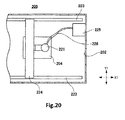
- FIG. 20 schematically shows the configuration of the additive manufacturing machine.
- the additive manufacturing (SL or SLA) machine, 200 has a hollow processing chamber 202 for performing a stereolithographic process, a support stage 204 disposed inside the processing chamber 202, and a dispensing head 221 for dispensing a powdered material onto the top surface of the stage 204.
- the SL machine 200 has a powder reservoir 225 for storing a powdered material, a transport pipe 226 for placing the reservoir 225 and the dispensing head 221 in communication with each other, and a powder transport mechanism (not shown) for transporting the powdered material from the powder reservoir 225 to the dispensing head 221 via the transport pipe 226.
- the dispensing head 221 is supported by first guide portions 223 and a second guide portion 224 so as to be movable in a direction parallel to one surface of the stage 204.
- Powder is transported from the powder reservoir 225 to the dispensing head 221 via the transport pipe 226 by the powder transport mechanism. Then, the dispensing head 221 is moved in a direction parallel to one surface of the stage 204 while being guided by the first guide portions 223 and second guide portion 224. The powdered material is dispensed onto one surface of the stage 204 from the dispensing head 221. As a result, the powdered material is tightly spread on one surface of the stage 204.
- patent document 1 discloses a technique for moving a restrictive member in the form of a flat plate in a horizontal direction along the top surface of an additive manufacturing frame for creating a 3D object to transport a powdered material onto the top surface of a support stage and tightly spreading the powdered material on the top surface of the stage such that a constant thickness is achieved across the whole powdered material.
- the additive manufacturing machine 200 shown in FIG. 20 has the problem that there is the danger that the transport pipe 226 interconnecting the powder reservoir 225 and the dispensing head 221 may be clogged with a powdered material and thus it may be impossible to stably dispense a powdered material onto the stage 204 from the dispensing head 221.
- the powdered material removed from the top surface of the stage is wasted.
- the material scatters within the processing chamber and adheres to the inner wall of the chamber, thus contaminating the interior of the chamber.
- an additive manufacturing machine as set out in claim 1.
- An additive manufacturing machine built in accordance with the teachings of the present invention for solving the foregoing problem has a support stage on which a powdered material for forming a 3D object stereolithographically is stacked as layers and a powder supply unit for spreading the powdered material tightly on the stage.
- the powder supply unit has a powder cartridge for accommodating the powdered material and dispensing the material onto the stage and at least one holding mechanism by which the powder cartridge is detachably held.
- the powder cartridge has a cartridge body for receiving an amount of the powdered material to be spread tightly as one or plural layers on the stage and a discharge port formed in the cartridge body to permit the powdered material to be discharged.
- the additive manufacturing machine according to the present invention does not have any transport pipe that would normally be clogged up with powdered material. Therefore, a powdered material can be stably supplied onto the support stage.
- the powdered material for creating a 3D object is received in plural volumes within the cartridge body of the powder cartridge. This can suppress the interior of the processing chamber from being contaminated with the powdered material. It is possible to prevent waste of the powdered material.
- FIGS. 1-19 Embodiments of the additive manufacturing machine of the present invention are hereinafter described with reference to FIGS. 1-19 .
- like components are indicated by like reference numerals.
- the various areas of the description are provided in the following order, the invention is not restricted to the following embodiments.
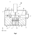
- FIG. 1 schematically shows the machine, 1.
- the additive manufacturing machine 1 shown in FIG. 1 is used to create a 3D object by irradiating a powdered material consisting of a metal such as titanium, aluminum, or iron with an electron beam to melt the material and stacking layers of the powdered material solidified on top of each other.
- the additive manufacturing machine 1 has a hollow processing chamber 2, an additive manufacturing frame 3, a support stage 4 in the form of a flat plate, a stage driving mechanism 5, a powder supply unit 7, an electron gun 8, and a cartridge housing receptacle 9.
- a direction that is parallel to one surface of the stage 4 is herein referred to as the first direction X1.
- a direction that is perpendicular to the first direction X1 and is parallel to one surface of the stage 4 is herein referred to as the second direction Y1.
- a direction that is perpendicular to one surface of the stage 4 is herein referred to as the third direction Z1.
- a vacuum pump (not shown) is connected to the processing chamber 2.
- the interior of the processing chamber 2 is maintained in vacuum by evacuating the ambient inside the processing chamber 2 by the vacuum pump.
- the additive manufacturing frame 3, stage 4, stage driving mechanism 5, and powder supply unit 7 are mounted inside the processing chamber 2.
- the cartridge housing receptacle 9 is connected to one side of the processing chamber 2 as viewed in the first direction X1.
- the electron gun 8 is mounted on one side of the processing chamber 2 as viewed in the third direction Z1, while the additive manufacturing frame 3 is disposed on the other side of the processing chamber 2 as viewed in the third direction Z1.
- the additive manufacturing frame 3 is provided with a pit 3a extending across the frame in the third direction Z1.
- the pit 3a forms an opening shaped like a quadrangular prism. A part of the outer periphery of the pit 3a in the additive manufacturing frame 3 is open to permit a completed 3D object P1 to be taken out.
- the support stage 4 and stage driving mechanism 5 are disposed in the pit 3a formed in the additive manufacturing frame 3.
- a metal powder M1 for stereolithographically creating the 3D object is stacked as layers on the support stage 4 that is a powder supporting stage.
- a sliding member 14 having heat resistance and flexibility is mounted at a lateral end of the stage 4. The sliding member 14 is slidably in contact with the wall surface of the pit 3a.
- the pit 3a is partitioned by the stage 4 into two spaces which are spaced from each other in the third direction Z1, and these spaces are hermetically sealed by the sliding member 14.
- a shaft portion 4d is mounted on the other surface of the stage 4 which faces away from the surface on which the metal powder M1 is stacked as layers.
- the shaft portion 4d protrudes from the other surface of the stage 4 toward the other side of the third direction Z1.
- the shaft portion 4d is connected to the stage driving mechanism 5 received in the pit 3a.
- the stage driving mechanism 5 drives the stage 4 via the shaft portion 4d in the third direction Z1.
- the stage driving mechanism 5 is a rack-and-pinion, ball screw, or the like.
- the electron gun 8 is disposed opposite to one surface 4a of the stage 4 on one side of the processing chamber 2 as viewed in the third direction Z1.
- the electron gun 8 emits an electron beam L1 at the metal powder M1 in accordance with each two-dimensional shape of the slices obtained by slicing a previously prepared design object at intervals of ⁇ Z, the design object being represented by three-dimensional CAD (computer-aided design) data.
- CAD computer-aided design
- FIGS. 2 and 3 are schematic plan views of the additive manufacturing machine. As shown in FIGS. 2 and 3 , the powder supply unit 7 has powder cartridges 21, holding mechanisms 22, a pair of first guide portions 23, and a second guide portion 24. The first guide portions 23 and second guide portion 24 together constitute one example of guide mechanism.
- the first guide portions 23 of one pair are disposed on opposite sides of the stage 4 as viewed in the second direction Y1.
- the first guide portions 23 extend into the processing chamber 2 along the first direction X1.
- the second guide portion 24 is supported on the first guide portions 23 so as to be movable in the first direction X1.
- the second guide portion 24 extends between the first guide portions 23 of one pair in the second direction Y1.
- the holding mechanisms 22 which are three in number are supported to the second guide portion 24 so as to be movable in the second direction Y1.
- the powder cartridges 21 are detachably held to the three holding mechanisms 22, respectively.
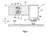
- FIG. 4 is a cross-sectional views of main portions of the powder supply unit 7. As shown in FIG. 4 , each of the powder cartridges 21 has a hollow cartridge body 26 for receiving the metal powder M1. An amount of metal powder M1 that will be spread tightly as one or more layers on the support stage 4 is received in the cartridge body 26.
- the cartridge body 26 is provided with an exhaust port 26a permitting the metal powder M1 to be discharged toward the support stage 4.
- Each powder cartridge 21 has a shutter member 27 that covers the exhaust port 26a in the cartridge body 26 such that the port 26a can be opened and closed.
- Each of the holding mechanisms 22 has a holding portion 31 by which a respective one of the powder cartridges 21 is detachably held, a rail engagement portion 32 making a sliding engagement with guide rails 24a mounted on the second guide portion 24, and a terminal connector 33.
- the terminal connector 33 has a cartridge connecting terminal 33a that is electrically connected with the shutter member 27 of the powder cartridge 21.
- the second guide portion 24 has a terminal receptor 25 into which the terminal connector 33 is inserted.
- the terminal receptor 25 has a guide terminal 25a that is electrically connected with the cartridge connecting terminal 33a mounted on the terminal connector 33.
- the three powder cartridges 21 and the three holding mechanisms 22 are mounted to the second guide portion 24.
- the number of the powder cartridges 21 and holding mechanisms 22 is not restricted to three. They may be two or less or four or more in number. Different types of metal powder M1 may be received in the cartridge bodies 26 of the three powder cartridges 21. Alternatively, the same type of metal powder M1 may be received in the cartridge bodies 26.
- FIG. 5 is a cross-sectional view showing the cartridge housing receptacle 9 and its vicinities. As shown in FIG. 5 , additional powder cartridges 21 loaded with the metal powder M1 are received in the cartridge housing receptacle 9. An exchange window 12 through which the powder cartridges are expelled is formed on the side of the cartridge housing receptacle 9 that is closer to the processing chamber 2. A pushing mechanism 35 is mounted on the side of the cartridge housing receptacle 9 that faces away from the exchange window 12.
- the pushing mechanism 35 is composed of a pushing plate 36 abutting against the powder cartridges 21 and a coil spring 37 biasing the pushing plate 36 toward the exchange window 12.
- the pushing mechanism 35 biases the stored powder cartridges 21 toward the exchange window 12.
- Stoppers (not shown) are mounted to the exchange window 12 of the cartridge housing receptacle 9 and bear against the powder cartridges 21 biased by the pushing mechanism 35 to restrict the cartridges 21 from being pushed out of the cartridge housing receptacle 9. When the powder cartridges 21 are exchanged, the stoppers are disengaged from the cartridges 21, and one cartridge 21 is handed over to the holding mechanisms 22.
- the pushing mechanism 35 is not restricted to the aforementioned pushing plate 36 and coil spring 37.
- a motor, a piston, high-pressure gas, and various other mechanisms may be used.
- a cartridge recovery receptacle 11 is mounted on the other side of the cartridge housing receptacle 9 as viewed in the third direction Z1. Each used powder cartridge 21B from which all the metal powder M1 has been expelled is discharged into the cartridge recovery receptacle 11.
- the used powder cartridge 21B recovered into the cartridge recovery receptacle 11 can be reused by loading it with new metal powder M1. Furthermore, the metal powder M1 remaining in the used powder cartridge 21B can be reused.
- FIG. 2 schematically shows main portions of the additive manufacturing machine 1, for illustrating its principal operations.
- the support stage 4 is moved into a position lower than the top surface of the additive manufacturing frame 3 by a distance ⁇ Z in the third direction Z1 by the stage driving mechanism 5.
- This distance ⁇ Z corresponds to the thickness of the layer of the metal powder M1 that will be spread tightly, the thickness being taken in the third direction Z1.
- the metal powder M1 is spread tightly over one surface of the support stage 4 up to the thickness ⁇ Z by the powder supply unit 7.
- the holding mechanisms 22 and powder cartridges 21 are moved toward the other side of the stage 4 as viewed in the third direction Z1 along the first guide portions 23 and second guide portion 24.
- the shutter member 27 of one powder cartridge 21 is opened.
- the metal powder M1 received in the powder cartridge 21 is discharged onto one surface 4a of the stage 4 from the exhaust port 26a.
- the electron gun 8 emits the electron beam L1 at the metal powder M1. Specifically, the electron gun 8 emits the electron beam L1 at the metal powder M1 in accordance with each two-dimensional shape of the slices obtained by slicing a previously prepared design object at intervals of ⁇ Z, the design object being represented by three-dimensional CAD (computer-aided design) data. As a result, a region of the metal powder M1 that corresponds to such two-dimensional shapes is molten.
- CAD computer-aided design
- the stage 4 is made to descend the distance ⁇ Z by the stage driving mechanism 5.
- the motion of the stage 4 in the third direction Z1 is accomplished by sliding motion of the sliding member 14 along the inner surface of the pit 3a formed in the additive manufacturing frame 3.
- the powder cartridge 21 is moved to one side of the stage 4 as viewed in the third direction Z1 again by the powder supply unit 7 to spread an amount of metal powder M1 corresponding to the distance ⁇ Z tightly on the layer formed immediately before, thus forming a second layer.
- a region of the metal powder M1 corresponding to a two-dimensional shape corresponding to the second layer is molten and solidified by the electron beam L1 emitted from the electron gun 8.
- This series of processing steps is carried out repeatedly to stack layers of the metal powder M1 molten and solidified on top of each other, thus building the 3D object P1. Consequently, the operation of the additive manufacturing machine 1 of the present embodiment is completed.
- Each used powder cartridge 21B which has been completely emptied of the metal powder M1 is transported into the cartridge housing receptacle 9 and into the cartridge recovery receptacle 11 as shown in FIGS. 3 and 5 .
- the used powder cartridges 21B are disengaged from the holding mechanisms 22 and recovered into the cartridge recovery receptacle 11.
- each holding mechanism 22 is inserted into the cartridge housing receptacle 9 through the exchange window 12 of the housing receptacle 9 and holds a new powder cartridge 21 loaded with the metal powder M1.
- the powder cartridge 21 is transferred to the holding mechanism 22 from the cartridge housing receptacle 9, the remaining powder cartridge 21 stored in the cartridge housing receptacle 9 is biased toward the exchange window 12 by the pushing mechanism 35. This moves the powder cartridge 21 held by the holding mechanism 22 into a reception position in the cartridge housing receptacle 9, where the cartridge 21 waits.
- an amount or amounts of the metal powder M1 for achieving one or plural layers for creating the 3D object are received in one or more of the plural powder cartridges 21. Where amounts of the powder M1 corresponding to the plural layers are received, they are separately received. This dispenses with any transport pipe for transporting the metal powder M1; otherwise, the transport pipe would be clogged with the metal powder M1. Consequently, the metal powder M1 can be stably supplied onto the stage 4 at all times.
- metal powder M1 Since the metal powder M1 is received in the cartridge bodies 26 of the powder cartridges 21, contamination of the interior of the processing chamber 2 with the metal powder M1 can be suppressed. Different types of metal powder M1 can be received in the cartridge bodies 26 of the three powder cartridges 21, respectively. As a result, plural types of metal powder M1 can be placed in given positions independently. Alternatively, the plural types of metal powder M1 may be placed in the same layer.
- the amount of metal powder M1 needed to create the 3D object P1 can be divided into smaller amounts and received in the plural powder cartridges 21 for managing purposes. In consequence, the metal powder M1 can be stored and managed easily. Furthermore, waste of the metal powder M1 can be prevented.
- FIG. 6 is a schematic plan view of an additive manufacturing machine, 41, associated with the second embodiment.
- FIG. 7 is a cross-sectional view of main portions of the additive manufacturing machine 41.
- FIG. 8 is a front elevation of the machine.
- the additive manufacturing machine 41 associated with the second embodiment is similar to the additive manufacturing machine 1 associated with the first embodiment except for the configuration of the mechanism for moving the powder supply unit 42 and for the number of powder cartridges. Therefore, only the powder supply unit 42 is described here.
- Those components of the machine 41 which are identical to their respective counterparts of the additive manufacturing machine 1 associated with the first embodiment are indicated by the same reference numerals as in the above cited figures and a description thereof is omitted.
- the powder supply unit 42 has the first guide portions 23, a second guide portion 44 mounted on the first guide portions 23, the plurality of holding mechanisms 22 fixedly mounted to the second guide portion 44, and powder cartridges 21.
- the first and second guide portions 23, 44 constitute a guide mechanism.
- the second guide portion 44 is supported to the first guide portions 23 so as to be movable in the first direction X1.
- the holding mechanisms 22 holding the powder cartridges 21 are secured on the second guide portion 44 without spaces therebetween along the scanning line on the stage 4 lying in the second direction Y1.
- the second guide portion 44 has homogenizing members 47 which extend from the second guide portion 44 while being spaced a given spacing either from one surface 4a of the stage 4 or from a surface (hereinafter referred to as the sample surface) M3 in the third direction Z1, the surface M3 being formed by the layer of metal powder M1 spread tightly on the stage 4.
- the homogenizing members 47 are placed behind the second guide portion 44 in the direction of motion.
- the homogenizing members 47 operate to destroy the top of a heap of the metal powder M1 discharged from each powder cartridge 21 and to make substantially uniform the thickness of the metal powder M1 discharged either onto one surface 4a of the stage 4 or onto the sample surface M3. Consequently, the metal powder M1 can be neatly spread to a given thickness on one surface 4a of the stage 4 or on the sample surface M3.
- the additive manufacturing machine 41 is similar to the additive manufacturing machine 1 associated with the first embodiment and so a description of such similarities is omitted.
- the additive manufacturing machine 41 having the power supply unit 42 can yield the same advantageous effects as the additive manufacturing machine 1 associated with the first embodiment.
- the powder supply unit 42 associated with the second embodiment makes it unnecessary to move the holding mechanisms 22 and the powder cartridges 21 in the second direction Y1. Hence, the moving mechanism can be made simpler in configuration than the powder supply unit 7 associated with the first embodiment.
- the powder supply unit 7 associated with the first embodiment may have the aforementioned homogenizing members 47.
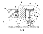
- FIGS. 9A, 9B , and 10 schematically show the configuration of the powder supply unit of this machine.
- This additive manufacturing machine associated with the third embodiment is similar to the additive manufacturing machine 1 associated with the first embodiment except for the configurations of a powder cartridge 51 of a powder supply unit 50 and of a holding mechanism 61. Therefore, only the powder cartridge 51 and holding mechanism 61 are described here.
- Those components of the machine associated with the third embodiment which are identical to their respective counterparts of the additive manufacturing machine 1 associated with the first embodiment are indicated by the same reference numerals as in the above cited figures and a description thereof is omitted.
- the powder cartridge 51 has a cartridge body 52, a shutter member 53 covering a discharge port 52a such that the port can be opened and closed, and an anti-clogging mechanism 54.
- the cartridge body 52 has an open surface at the end facing away from the discharge port 52a.
- a bearing portion 58 and a connector portion 59 are mounted to close off the opening of the cartridge body 52.
- the bearing portion 58 is shaped like a flat plate and provided with a bearing hole 58a.
- the connector portion 59 that is cylindrical in shape is fixedly mounted to one surface of the bearing portion 58 which faces away from the cartridge body 52.
- the anti-clogging mechanism 54 has rotary blades 55, a shaft 56, and a driven gear 57.
- the rotary blades 55 are secured to one axial end of the shaft 56.
- the rotary blades 55 are disposed opposite to the discharge port 52a within the cartridge body 52.
- the rotary blades 55 are arranged radially.
- the front ends of the rotary blades 55 are located close to the discharge port 52a.
- the shaft 56 is rotatably supported in the bearing hole 58a of the bearing portion 58.
- One axial end of the shaft 56 is inserted in the cartridge body 52.
- the other axial end protrudes from the bearing portion 58 toward the connector portion 59.
- the driven gear 57 is secured to the other axial end of the shaft 56.
- the holding mechanism 61 has a holding portion 62, an arm portion 63, a driving portion 64, a rail engagement portion 65, and a terminal connector 66.
- the arm portion 63 has the driving portion 64 formed at one end of the holding portion 62 as viewed in the third direction Z1.
- the driving portion 64 When the holding portion 62 holds the powder cartridge 51, the driving portion 64 is inserted into the connector portion 59 of the cartridge 51.
- the driving portion 64 has a driving gear that meshes with the driven gear 57.
- the driving portion 64 rotates the rotary blades 55 via the driven gear 57 and the shaft 56.
- the additive manufacturing machine associated with the third embodiment is similar to the additive manufacturing machine 1 associated with the first embodiment. A description of such similarities is omitted.
- the additive manufacturing machine having the powder supply unit 50 described above can yield the same advantageous effects as the additive manufacturing machine 1 associated with the first embodiment.
- the anti-clogging mechanism is not restricted to the foregoing configuration.
- One example of the anti-clogging mechanism is a vibratory mechanism for vibrating the cartridge body 52.
- Another example is accomplished by partitioning the interior of the cartridge body 52 and limiting the amount of the metal powder M1 discharged from the discharge port 52a using a restrictive member or any other mechanism.
- FIGS. 11A,11B , 12, 13 A fourth embodiment of the additive manufacturing machine of the present invention is next described by referring to FIGS. 11A,11B , 12, 13 .
- FIGS. 11A, 11B , and 12 schematically show main portions of the powder supply unit of the additive manufacturing machine associated with the fourth embodiment.
- the additive manufacturing machine associated with the fourth embodiment is similar to the additive manufacturing machine 1 associated with the first embodiment except for the configurations of a powder cartridge 71 of a powder supply unit 70 and of a holding mechanism. Therefore, only the powder cartridge 71 is described here.
- Those components of the additive manufacturing machine associated with the fourth embodiment which are identical to their respective counterparts of the additive manufacturing machine 1 associated with the first embodiment are indicated by the same reference numerals as in the above cited figures and a description thereof is omitted.
- the holding mechanism is identical in configuration to the holding mechanism 61 associated with the third embodiment and so a description of the holding mechanism is omitted.
- the powder cartridge 71 has a cartridge body 72, a shutter member 73 covering a discharge port 72a such that the port can be opened and closed, and a pulverizing mechanism 80.
- the cartridge body 72 has a bearing portion 78 and a connector portion 79 similarly to the cartridge body 52 associated with the third embodiment.
- the bearing portion 78 is provided with a bearing hole 78a.
- the pulverizing member 80 has a rubbing member 74 and a rubbed member 81.
- the rubbing member 74 has a pulverizing portion 75, a shaft 76, and a driven gear 77.
- the pulverizing portion 75 is secured to axial one end of the shaft 76.
- the pulverizing portion 75 is shaped like a circular cone and has plural rubbing pieces arranged radially.
- the front end of the pulverizing portion 75 extends through the rubbed member 81 (described later) and is disposed close to the exhaust port 72a.
- the shaft 76 is rotatably supported to the bearing hole 78a formed in the bearing portion 78.
- One axial end of the shaft 76 is inserted in the cartridge body 72.
- the other axial end protrudes from the bearing portion 78 toward the connector portion 79.
- the driven gear 77 is secured to the other axial end of the shaft 76.
- the rubbed member 81 is disposed opposite to the discharge port 72a within the cartridge body 72.
- the rubbed member 81 has a rubbed portion 82 and a flange 83.
- the rubbed portion 82 is shaped like a hollow circular cone.
- the rubbed portion 82 is provided with a through-hole 82a at its apex.
- the front end of the pulverizing portion 75 extends through the through-hole 82a.
- the rubbed portion 82 is mounted inside the cartridge body 72 such that the through-hole 82a faces the discharge port 72a.
- the flange 83 is mounted on the outer fringes of the rubbed portion 82 that is on the opposite side of the through-hole 82a.
- the flange 83 protrudes radially outwardly from the outer fringes of the rubbed portion 82, and is fixedly secured to the inner wall of the cartridge body 72.
- the flange 83 has insertion holes 83a through which the metal powder M1 passes. The openings of the holes 83a are set greater in diameter than the grains of the metal powder M1.
- a part of the metal powder M1 received in the cartridge body 72 passes through the insertion holes 83a in the flange 83.
- the remaining of the metal powder M1 enters the gap between the pulverizing portion 75 of the rubbing member 74 and the rubbed portion 82 of the rubbed member 81.
- the metal powder M1 interposed in the gap between the pulverizing portion 75 and the rubbed portion 82 is scraped.
- the metal powder M1 and pulverized powder M2 having smaller particle diameters than the metal powder M1 are expelled from the discharge port 72a.
- FIG. 13 shows the state of the metal powder M1 and pulverized powder M2 discharged from the powder cartridge 71.
- the granules of the pulverized powder M2 discharged from the powder cartridge 71 enter between two adjacent grains of the metal powder M1. Consequently, the area of contact between any two adjacent grains of the metal powder M1 can be increased.
- a preheating operation is performed in the additive manufacturing machine before the metal powder M1 is molten.
- the preheating operation consists of melting the surface of the metal powder M1, thus weakening the bonding between the grains of the metal powder M1.
- the granules of the pulverized powder M2 entering between the grains of the metal powder M1 are molten by preheating. This can enhance the degree of bonding between the grains of the metal powder M1 during the preheating. Since the pulverized powder M2 is molten with a smaller amount of heat than needed for the metal powder M1, the time taken to perform the preheating can be shortened. In addition, the melting can be done without performing the preheating.
- the pulverizing mechanism 80 acts also as an anti-clogging mechanism and assures that the metal powder M1 is discharged from the cartridge body 72 stably.
- the additive manufacturing machine associated with the fourth embodiment is similar in configuration to the additive manufacturing machine 1 associated with the first embodiment and so a description of such similarities is omitted.
- the additive manufacturing machine having the powder supply unit 70 can yield the same advantageous effects as the additive manufacturing machine 1 associated with the first embodiment.
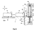
- FIGS. 14A, 14B , 15-18 show a powder supply unit.
- FIG. 15 is a cross-sectional view of main portions of the additive manufacturing machine.
- the additive manufacturing machine associated with the fifth embodiment is similar to the additive manufacturing machine 1 associated with the first embodiment except for the configurations of the powder cartridge of the powder supply unit and of the holding mechanism and for the provision of a cartridge exchanging mechanism. Therefore, only the powder cartridge, holding mechanism, and cartridge exchanging mechanism are described here.
- Those components of the additive manufacturing machine associated with the fifth embodiment which are identical to their respective counterparts of the additive manufacturing machine 1 associated with the first embodiment are indicated by the same reference numerals as in the above cited figures and a description thereof is omitted.
- the powder supply unit, 90 has the powder cartridge, 91, the holding mechanism, 92, by which the powder cartridge 91 is detachably held, and a moving mechanism (not shown).
- the holding mechanism 92 has a mechanism body 93, a holding portion 94 by which the powder cartridge 91 is detachably held, a rotary portion 95, and a hold-down member 97.
- the rotary portion 95 is rotatably mounted to the mechanism body 93 via a first rotating shaft 96.
- the rotary portion 95 is provided with a sliding groove 95a.
- the holding portion 94 is slidably supported in the sliding groove 95a.
- the holding portion 94 slides in the sliding groove 95a and moves to the other side of the third direction Z1, i.e., vertically downwardly.
- the mechanism body 93 has a mounting recess 93a in which the rotary portion 95, the holding portion 94, and the powder cartridge 91 are arranged, the cartridge 91 being held to the holding portion 94.
- the holding portion 94 and the powder cartridge 91 are placed outside the mounting recess 93a of the mechanism body 93.
- the rotary portion 95 rotates, and the holding portion 94 and powder cartridge 91 are placed in the mounting recess 93a.
- the hold-down member 97 is rotatably mounted in the mounting recess 93a via a secondary rotating shaft 98.
- the hold-down member 97 is provided with a recess 97a in which the end of the powder cartridge 91 on the opposite side of a discharge port 121a is inserted, the cartridge 91 being placed in the mounting recess 93a. Consequently, the hold-down member 97 restricts motion of the powder cartridge 91 within the mounting recess 93a. As a result, when the metal powder M1 is discharged, it is possible to prevent the cartridge 91 from moving out of position.
- an exchange window 101 is formed in a wall surface that is located on one side of the processing chamber 2 as viewed in the first direction X1.
- a seal member 101a is mounted on the end of the exchange window 101 that is closer to the processing chamber 2.
- a cartridge exchanging mechanism 100 is positioned on one side of the exchange window 101 as viewed in the first direction X1.
- the exchange window 101 places the processing chamber 2 and the cartridge exchanging mechanism 100 in communication with each other.
- the cartridge exchanging mechanism 100 is next described by referring to FIGS. 15 , 16A, 16B , 17A-17C .
- the cartridge exchanging mechanism 100 has an exchange cylinder 102, an exchange passage 103 in which the exchange cylinder 102 is movably positioned, a gas nozzle 104 ejecting high-pressure gas, and a biasing member 105 for biasing the exchange cylinder 102.
- the exchange passage 103 extends in the third direction Z1 on one side of the exchange window 101 as viewed in the first direction X1.
- the exchange passage 103 is shaped cylindrically and places the exchange window 101 and the cartridge housing receptacle 9 in communication with each other.
- An exhaust port 103a is formed in the exchange passage 103 at a position located opposite to the exchange window 101.
- a vacuum pump is connected to the exhaust port 103a via an open-close valve (not shown).
- the gas nozzle 104 is mounted on one side of the exchange passage 103 as viewed in the third direction Z1.
- the gas nozzle 104 has an ejection port 104a jetting out high-pressure gas and a discharge port 104b.
- the high-pressure gas is ejected from the ejection port 104a of the gas nozzle 104 toward the exchange passage 103.
- the exchange cylinder 102 is mounted in the exchange passage 103 so as to be movable in the third direction Z1.
- FIG. 16A is a cross-sectional view of the exchange cylinder 102.
- FIG. 16B is a cross-sectional view of the cartridge exchanging mechanism 100, taken from one side of the first direction X1.
- FIGS. 17A-17C and 18 illustrate an operation for exchanging the powder cartridge 91.
- the exchange cylinder 102 is shaped cylindrically and has one axial end closed off. The other axial end is open. As shown in FIG. 16B , the exchange cylinder 102 is movably positioned within the exchange passage 103. As shown in FIG. 16A , an insertion window 102a and a receipt port 102b are formed in the side surface of the exchange cylinder 102.
- the insertion window 102a is formed in the side surface of the exchange cylinder 102 that is closer to the exchange window 101 and extends continuously from end to end axially. As shown in FIG. 16B , the powder cartridge 91 and the holding portion 94 of the holding mechanism 92 are withdrawably inserted in the insertion window 102a.
- the receipt port 102b formed in the side surface of the exchange cylinder 102 is located opposite to the insertion window 102a.
- the receipt port 102b faces the exhaust port 103a of the exchange passage 103.
- the receipt port 102b faces the opening of the cartridge housing receptacle 9.
- a gas receiving recess 102c is formed at one axial end of the exchange cylinder 102.
- the gas receiving recess 102c extends from one axial end toward the other axial end of the exchange cylinder 102.
- High-pressure gas ejected from the ejection port 104a of the gas nozzle 104 is blown against the gas receiving recess 102c.
- a bottom plate 112 in the form of a flat plate is securely mounted to the other axial end of the exchange cylinder 102, thus closing off the opening.
- the bottom plate 112 has an engagement portion 113 that engages an engagement groove 121b ( FIG. 18 ) formed in the powder cartridge 91.
- the engagement portion 113 is secured to the bottom plate 112 and disposed at the other axial end of the exchange cylinder 102.
- a cylinder sealing member 114 is mounted on one surface of the bottom plate 112.
- the cylinder sealing member 114 is made, for example, of an O-ring and mounted to surround the outer periphery of the exchange cylinder 102 on one surface of the bottom plate 112.
- the cylinder sealing member 114 is in intimate contact with the wall surface of the processing chamber 2 located on the other side of the third direction Z1. Consequently, the exchange passage 103 and the opening on the side of the cartridge housing receptacle 9 are closed off while interposing the bottom plate 112 therebetween.
- a space present on one side of the bottom plate 112 as viewed in the third direction Z1 is hermetically sealed.
- the biasing member 105 is mounted on the surface of the bottom plate 112 that faces away from the surface on which the exchange cylinder 102 is secured.
- the biasing member 105 is made, for example, of a coil spring having resilience.
- One end of the biasing member 105 is held to the bottom plate 112.
- the other end of the biasing member 105 is held to a spring receiving portion 106 which is located opposite to the bottom plate 112 and close to the opening of the cartridge housing receptacle 9.
- the biasing member 105 biases the exchange cylinder 102 via the bottom plate 112 to one side of the third direction Z1 at all times.
- the spring receiving portion 106 is a recess extending from one surface to the other surface of the cartridge housing receptacle 9 as viewed in the third direction Z1.
- the cartridge housing receptacle 9 is positioned on one side of the spring receiving portion 106 as viewed in the first direction X1.
- a recovery passage 131 in communication with the cartridge recovery receptacle 11 is formed on the other side of the spring receiving portion 106 as viewed in the first direction X1.
- FIGS. 15 , 17A-17C , and 18 An operation for exchanging the powder cartridge 91 by the use of the cartridge exchanging mechanism 100 having the above-described configuration is next described by referring to FIGS. 15 , 17A-17C , and 18 .
- the position of the exchange cylinder 102 shown in FIG. 17A is herein referred to as the reception position, while the position of the exchange cylinder 102 shown in FIG. 17C is referred to as the exchange position.
- the holding mechanism 92 first rotates the rotary portion 95 to make the discharge port 121a of the powder cartridge 91 face to one side of the third direction Z1.
- the holding mechanism 92 is moved to one side of the first direction X1 by a moving mechanism (not shown) and approaches the exchange window 101.
- the exchange cylinder 102 is positioned in the exchange position as shown in FIG. 17A , a part of the other side of the insertion window 102a as viewed in the third direction Z1 faces the exchange window 101 and the receipt port 102b faces the exhaust port 103a.
- the cylinder sealing member 114 is in intimate contact with the wall surface of the processing chamber 2 on the other side of the third direction Z1.
- the bottom plate 112 closes off the opening of the exchange passage 103 that is on the other side of the third direction Z1.
- a vacuum pump (not shown) that is in operation at all times is connected with the exhaust port 103a via an open-close valve. In the state shown in FIG. 17A , the open-close valve connected with the exhaust port 103a is closed.
- the powder cartridge 91 and the holding portion 94 are inserted into the interior space of the exchange cylinder 102 by the holding mechanism 92.
- the opening of the exchange chamber 101 closer to the processing chamber 2 is closed off by the holding mechanism 92.
- the seal member 101a mounted on the exchange window 101 is in intimate contact with the holding mechanism 92.
- the exchange window 101 is closed, hermetically sealing the space inside of the processing chamber 2.
- the engagement portion 113 disposed in the exchange cylinder 102 engages the engagement groove 121b formed in the powder cartridge 91.
- the insertion window 102a formed in the exchange cylinder 102 extends continuously from end to end axially of the exchange cylinder 102. This can prevent the holding portion 94 of the holding mechanism 92 inserted in the exchange cylinder 102 from interfering with the exchange cylinder 102. At this time, the interior of the exchange cylinder 102 is exposed to atmosphere. However, as described previously, the seal member 101a for the exchange window 101 is in intimate contact with the holding mechanism 92, thus hermetically sealing the space on the side of the processing chamber 2. In consequence, the interior of the processing chamber 2 can be maintained in vacuum.
- the gas inside the exchange passage 103 is evacuated from the discharge port 104b of the gas nozzle 104.
- the exhaust port 103a formed in the exchange passage 103 is closed off by the wall surface of the exchange cylinder 102.
- the exchange cylinder 102 is biased by the biasing member 105 and slides toward one side of the third direction Z1 through the exchange passage 103. This brings the engagement portion 113 into engagement with the engagement groove 121b formed in the new powder cartridge 91A.
- the new cartridge 91A is loaded in the exchange cylinder 102.
- the open-close valve connected to the exhaust port 103a is closed.
- the exchange cylinder 102 moves into the reception position in the exchange passage 103.
- the open-close valve connected to the exhaust port 103a is then opened, and the gas inside the exchange cylinder 102 is evacuated from the exhaust port 103a using the vacuum pump (not shown).
- an open-close valve 122 that is one example of a shutter member mounted on the cartridge body 121 of the powder cartridge 91 is opened.
- the discharge port 121a is opened.
- the powder cartridge 91 is loaded in the exchange cylinder 102 while the discharge port 91a faces one side of the third direction Z1 that is vertically upward. Therefore, inert gas loaded in the cartridge body 121 of the powder cartridge 91 together with the metal powder M1 can be evacuated quickly from the discharge port 121a.
- the open-close valve 122 is actuated to close the discharge port 121a. Then, the powder cartridge 91 is held by the holding portion 94 of the holding mechanism 92.
- the holding mechanism 92 is moved to the other side of the first direction X1. The holding portion 94 is pulled out of the insertion window 102a in the exchange cylinder 102 and out of the exchange window 101. Since the powder cartridge 91 moves substantially horizontally in the first direction X1, the engagement portion 113 comes out of the engagement groove 121b formed in the powder cartridge 91, whereby the engagement portion 113 disengages from the engagement groove 121b.
- the holding mechanism 92 rotates the rotary portion 95 such that the discharge port 121a of the powder cartridge 91 faces to the other side of the third direction Z1, i.e., faces the additive manufacturing frame 3 and one surface 4a of the stage 4.
- the operation for exchanging the powder cartridge 91 ends.
- the additive manufacturing machine associated with the fifth embodiment is similar to the additive manufacturing machine 1 associated with the first embodiment and so a description of such similarities is omitted.
- the additive manufacturing machine having the powder supply unit 90 and the cartridge exchanging mechanism 100 can yield the same advantageous effects as the additive manufacturing machine 1 associated with the first embodiment.
- the powder cartridge 91 can be exchanged simply by reciprocating the exchange cylinder 102 once between the reception position and the exchange position in the third direction Z1. This can speed up the work for exchanging the powder cartridge 91.
- One or plural layers of the metal powder M1 for creating a 3D object stereolithographically are received separately inside the cartridge body 121 of the powder cartridge 91. This can reduce the amount of metal powder that can be accommodated in the powder cartridge 91. This in turn can reduce the volume of the exchange cylinder 102. Hence, the time taken to evacuate the interior of the exchange cylinder 102 can be shortened.
- an exchange cylinder moving mechanism for moving the exchange cylinder 102 is the biasing member 105 including a high-pressure gas and a coil spring.
- the cylinder moving mechanism is not restricted to this example.
- the cylinder moving mechanism for moving the exchange cylinder 102 can be a combination of an electric motor and a gear, a linear motor, a cylinder, and any of various other moving mechanisms.
- FIG. 19 is a cross-sectional view of main portions of an additive manufacturing machine associated with the modification.
- the additive manufacturing machine shown in FIG. 19 is similar to the additive manufacturing machine associated with the fifth embodiment except for the configurations of the cartridge storage receptacle and of the cartridge recovery receptacle. Therefore, only the cartridge storage receptacle and the cartridge recovery receptacle are described here. Those components of the additive manufacturing machine shown in FIG. 19 which are identical to their respective counterparts of the additive manufacturing machine associated with the fifth embodiment are indicated by the same reference numerals as in FIGS. 14A-18 and a description thereof is omitted.
- a cartridge storage receptacle 140 has a cartridge storage chamber 141, a storage intermediate chamber 142, and a storage waiting chamber 143.
- a first open-close door 144 is mounted between the cartridge storage chamber 141 and the storage intermediate chamber 142.
- a second open-close door 145 is mounted between the storage intermediate chamber 142 and the storage waiting chamber 143.
- a plurality of unused, new powder cartridges 91 is received in the cartridge storage chamber 141.
- the ambient in the cartridge storage chamber 141 is set equal to the atmospheric pressure.
- a vacuum pump (not shown) is connected to the storage intermediate chamber 142.
- the interior of the storage intermediate chamber 142 is converted from atmospheric state to vacuum state by evacuating the storage intermediate chamber 142 by the vacuum pump.
- the first open-close door 144 and the second open-close door 145 are closed. Then, the vacuum pump is operated to convert the state of the storage intermediate chamber 142 from atmospheric state to vacuum state. Thus, the operation for evacuating the inert gas loaded in the powder cartridge 91 is completed. Then, the second open-close door 145 is opened. The powder cartridge 91 are transported from the storage intermediate chamber 142 to the storage waiting chamber 143.
- the storage waiting chamber 143 is in communication with the exchange passage 103 of the cartridge exchanging mechanism 100.
- the storage waiting chamber 143 gives the exchange position where the exchange cylinder 102 is exchanged.
- This storage waiting chamber 143 is maintained in vacuum. Therefore, in this modification, for the powder cartridge 91 disposed in this exchange position, an operation for evacuating inert gas is already completed. Consequently, when the cartridge exchanging mechanism 100 performs an exchanging operation, it is not necessary to perform evacuation. For this reason, it is not necessary to form the exhaust port 103a in the exchange passage 103. Consequently, evacuation of the powder cartridge 91 can be dispensed with. This permits the cartridge exchanging mechanism 100 to perform an exchanging operation more quickly.
- a cartridge recovery receptacle 150 has a cartridge recovery chamber 151, a recovery intermediate chamber 152, and a recovery waiting chamber 153.
- a first open-close door 154 is mounted between the cartridge recovery chamber 151 and the recovery intermediate chamber 152.
- a second open-close door 155 is mounted between the recovery intermediate chamber 152 and the recovery waiting chamber 153.
- the recovery waiting chamber 153 is in communication with the recovery passage 131 and maintained in vacuum. A used powder cartridge 91B is transported into the recovery waiting chamber 153 through the recovery passage 131.
- a vacuum pump (not shown) is connected to the recovery intermediate chamber 152.
- the state of the recovery intermediate chamber 152 is converted from atmospheric state to vacuum state.
- the second open-close door 155 is opened and the used powder cartridge 91B is transported from the recovery waiting chamber 153.
- the ambient inside the cartridge recovery chamber 151 is set equal to the atmospheric pressure.
- the first open-close door 154 is opened after the second open-close door 155 is closed. As a consequence, the state of the recovery waiting chamber 153 can be kept in vacuum state.
- the used powder cartridge 91B is transported from the recovery intermediate chamber 152 into the cartridge recovery chamber 151, where the used powder cartridge 91B is recovered. Since it is not necessary to bring the cartridge recovery chamber 151 to a vacuum state, the used powder cartridge 91B can be recovered easily.
- the additive manufacturing machine associated with this modification is similar to the additive manufacturing machine 1 associated with the first embodiment and to the additive manufacturing machine associated with the fifth embodiment and, therefore, a description of such similarities is omitted.
- the additive manufacturing machine having the cartridge storage receptacle 140 and cartridge recovery receptacle 150 can yield the same advantageous effects as the additive manufacturing machine 1 associated with the first embodiment and the additive manufacturing machine associated with the fifth embodiment.
- powder of a metal such as titanium, aluminum, or iron is used as a powdered material.
- a resinous material may be used as the powdered material.
- an electron gun emitting an electron beam has been described as one example of melting mechanism that melts a powdered material.
- the invention is not restricted to this example.
- a laser emitting laser light may be used as the melting mechanism.
Abstract
Description
- The present invention relates to an additive manufacturing machine for fabricating a three-dimensional object by spreading a powdered material on a support stage to form a thin layer of the powdered material and stacking such layers on top of each other one by one.
- In recent years, techniques for fabricating a three-dimensional (3D) object by spreading a powdered material to form a thin layer and stacking such layers on top of each other one by one have attracted lots of attention, and many kinds of additive manufacturing techniques have been developed using different powdered materials and different additive manufacturing procedures.
- A related art method of fabricating a three-dimensional (3D) object stereolithographically consists of spreading a powdered material tightly on the top surface of a powder stage to form a layer, creating such layers, melting only a two-dimensional structure portion corresponding to one slice of the 3D object formed by the powdered material spread on the stage by a melting mechanism producing an electron beam or laser light, and stacking such layers on top of each other one by one in the direction of height (Z-direction).
- One conventional additive manufacturing machine is next described by referring to
FIG. 20 , which schematically shows the configuration of the additive manufacturing machine. As shown inFIG. 20 , the additive manufacturing (SL or SLA) machine, 200, has ahollow processing chamber 202 for performing a stereolithographic process, asupport stage 204 disposed inside theprocessing chamber 202, and a dispensinghead 221 for dispensing a powdered material onto the top surface of thestage 204. Furthermore, theSL machine 200 has apowder reservoir 225 for storing a powdered material, atransport pipe 226 for placing thereservoir 225 and the dispensinghead 221 in communication with each other, and a powder transport mechanism (not shown) for transporting the powdered material from thepowder reservoir 225 to the dispensinghead 221 via thetransport pipe 226. The dispensinghead 221 is supported byfirst guide portions 223 and asecond guide portion 224 so as to be movable in a direction parallel to one surface of thestage 204. - Powder is transported from the
powder reservoir 225 to the dispensinghead 221 via thetransport pipe 226 by the powder transport mechanism. Then, the dispensinghead 221 is moved in a direction parallel to one surface of thestage 204 while being guided by thefirst guide portions 223 andsecond guide portion 224. The powdered material is dispensed onto one surface of thestage 204 from the dispensinghead 221. As a result, the powdered material is tightly spread on one surface of thestage 204. - Furthermore,
patent document 1 discloses a technique for moving a restrictive member in the form of a flat plate in a horizontal direction along the top surface of an additive manufacturing frame for creating a 3D object to transport a powdered material onto the top surface of a support stage and tightly spreading the powdered material on the top surface of the stage such that a constant thickness is achieved across the whole powdered material. -
- Patent document 1:
JP-A-2001-152204 - The
additive manufacturing machine 200 shown inFIG. 20 has the problem that there is the danger that thetransport pipe 226 interconnecting thepowder reservoir 225 and the dispensinghead 221 may be clogged with a powdered material and thus it may be impossible to stably dispense a powdered material onto thestage 204 from the dispensinghead 221. - Furthermore, in the technique disclosed in
patent document 1, the powdered material removed from the top surface of the stage is wasted. In addition, when powdered material is transported by the restrictive member, the material scatters within the processing chamber and adheres to the inner wall of the chamber, thus contaminating the interior of the chamber. - In consideration of the foregoing problems, it would be desirable to provide an additive manufacturing machine capable of stably supplying a powdered material onto a support stage and suppressing the interior of a processing chamber from being contaminated with the powdered material.
- According to the present invention, there is provided an additive manufacturing machine as set out in
claim 1. - An additive manufacturing machine built in accordance with the teachings of the present invention for solving the foregoing problem has a support stage on which a powdered material for forming a 3D object stereolithographically is stacked as layers and a powder supply unit for spreading the powdered material tightly on the stage. The powder supply unit has a powder cartridge for accommodating the powdered material and dispensing the material onto the stage and at least one holding mechanism by which the powder cartridge is detachably held. The powder cartridge has a cartridge body for receiving an amount of the powdered material to be spread tightly as one or plural layers on the stage and a discharge port formed in the cartridge body to permit the powdered material to be discharged.
- The additive manufacturing machine according to the present invention does not have any transport pipe that would normally be clogged up with powdered material. Therefore, a powdered material can be stably supplied onto the support stage. The powdered material for creating a 3D object is received in plural volumes within the cartridge body of the powder cartridge. This can suppress the interior of the processing chamber from being contaminated with the powdered material. It is possible to prevent waste of the powdered material.
-
-
FIG. 1 is a schematic vertical cross section of an additive manufacturing machine associated with a first embodiment of the present invention. -
FIG. 2 is a schematic plan view of the additive manufacturing machine shown inFIG. 1 . -
FIG. 3 is a schematic plan view similar toFIG. 2 , but showing a different state. -
FIG. 4 is a cross-sectional view of main portions of a powder supply unit included in the additive manufacturing machine shown inFIG. 1 . -
FIG. 5 is a cross-sectional view showing a cartridge storage receptacle and its vicinities, the receptacle being included in the additive manufacturing machine shown inFIG. 1 . -
FIG. 6 is a schematic plan view of an additive manufacturing machine according to a second embodiment of the present invention. -
FIG. 7 is a cross-sectional view of main portions of a powder supply unit included in the additive manufacturing machine shown inFIG. 6 . -
FIG. 8 is a front elevation of the powder supply unit shown inFIG. 7 . -
FIG. 9A is a plan view of a powder cartridge included in an additive manufacturing machine associated with a third embodiment of the invention. -
FIG. 9B is a cross-sectional view of the powder cartridge shown inFIG. 9A . -
FIG. 10 is a cross-sectional view of main portions of a powder supply unit included in the additive manufacturing machine associated with the third embodiment. -
FIG. 11A is a plan view of a powder cartridge included in an additive manufacturing machine associated with a fourth embodiment of the invention. -
FIG. 11B is a cross-sectional view of the powder cartridge shown inFIG. 11A . -
FIG. 12 is an enlarged cross-sectional view of main portions of the powder cartridge shown inFIGS. 11A and 11B . -
FIG. 13 is an explanatory view illustrating a state of grains of a powdered material discharged from the powder cartridge shown inFIG. 12 . -
FIG. 14A is a cross-sectional view of main portions of a powder supply unit included in an additive manufacturing machine associated with a fifth embodiment of the invention. -
FIG. 14B is a side elevation of main portions of the powder supply unit shown inFIG. 14A . -
FIG. 15 is a cross-sectional view of a powder supply unit and a cartridge exchanging mechanism included in the additive manufacturing machine associated with the fifth embodiment. -
FIG. 16A is a cross-sectional view of an exchange cylinder of the cartridge exchanging mechanism shown inFIG. 15 . -
FIG. 16B is a cross-sectional view of the cartridge exchanging mechanism shown inFIGS. 15 and16A , taken along a plane. -
FIGS. 17A-17C are explanatory views illustrating an exchange operation of the cartridge exchanging mechanism shown inFIGS. 15 ,16A, and 16B . -
FIG. 18 is a cross-sectional view of the cartridge exchanging mechanism of the additive manufacturing machine shown inFIGS. 15 ,16A, and 16B , illustrating an exchanging operation performed by the cartridge exchanging mechanism. -
FIG. 19 is a cross-sectional view showing a modification of the additive manufacturing machine associated with the fifth embodiment. -
FIG. 20 is a schematic cross-sectional view of a related art additive manufacturing machine. - Embodiments of the additive manufacturing machine of the present invention are hereinafter described with reference to
FIGS. 1-19 . In the various figures, like components are indicated by like reference numerals. Although the various areas of the description are provided in the following order, the invention is not restricted to the following embodiments. - 1. First Embodiment
- 1-1. Configuration of Additive manufacturing Machine
- 1-2. Operation of Additive manufacturing Machine
- 2. Second Embodiment
- 3. Third Embodiment
- 4. Fourth Embodiment
- 5. Fifth Embodiment
- 5-1. Configuration of Additive manufacturing Machine
- 5-2. Operation for Exchanging Powder Cartridge
- 5-3. Modification
- A first embodiment of the additive manufacturing machine of the present invention is first described by referring to
FIG. 1 , which schematically shows the machine, 1. Theadditive manufacturing machine 1 shown inFIG. 1 is used to create a 3D object by irradiating a powdered material consisting of a metal such as titanium, aluminum, or iron with an electron beam to melt the material and stacking layers of the powdered material solidified on top of each other. - The
additive manufacturing machine 1 has ahollow processing chamber 2, anadditive manufacturing frame 3, asupport stage 4 in the form of a flat plate, astage driving mechanism 5, apowder supply unit 7, anelectron gun 8, and acartridge housing receptacle 9. A direction that is parallel to one surface of thestage 4 is herein referred to as the first direction X1. A direction that is perpendicular to the first direction X1 and is parallel to one surface of thestage 4 is herein referred to as the second direction Y1. A direction that is perpendicular to one surface of thestage 4 is herein referred to as the third direction Z1. - A vacuum pump (not shown) is connected to the
processing chamber 2. The interior of theprocessing chamber 2 is maintained in vacuum by evacuating the ambient inside theprocessing chamber 2 by the vacuum pump. Theadditive manufacturing frame 3,stage 4,stage driving mechanism 5, andpowder supply unit 7 are mounted inside theprocessing chamber 2. Thecartridge housing receptacle 9 is connected to one side of theprocessing chamber 2 as viewed in the first direction X1. Theelectron gun 8 is mounted on one side of theprocessing chamber 2 as viewed in the third direction Z1, while theadditive manufacturing frame 3 is disposed on the other side of theprocessing chamber 2 as viewed in the third direction Z1. - The
additive manufacturing frame 3 is provided with apit 3a extending across the frame in the third direction Z1. Thepit 3a forms an opening shaped like a quadrangular prism. A part of the outer periphery of thepit 3a in theadditive manufacturing frame 3 is open to permit a completed 3D object P1 to be taken out. - The
support stage 4 andstage driving mechanism 5 are disposed in thepit 3a formed in theadditive manufacturing frame 3. A metal powder M1 for stereolithographically creating the 3D object is stacked as layers on thesupport stage 4 that is a powder supporting stage. A slidingmember 14 having heat resistance and flexibility is mounted at a lateral end of thestage 4. The slidingmember 14 is slidably in contact with the wall surface of thepit 3a. Thepit 3a is partitioned by thestage 4 into two spaces which are spaced from each other in the third direction Z1, and these spaces are hermetically sealed by the slidingmember 14. - A
shaft portion 4d is mounted on the other surface of thestage 4 which faces away from the surface on which the metal powder M1 is stacked as layers. Theshaft portion 4d protrudes from the other surface of thestage 4 toward the other side of the third direction Z1. Theshaft portion 4d is connected to thestage driving mechanism 5 received in thepit 3a. Thestage driving mechanism 5 drives thestage 4 via theshaft portion 4d in the third direction Z1. Thestage driving mechanism 5 is a rack-and-pinion, ball screw, or the like. - The
electron gun 8 is disposed opposite to onesurface 4a of thestage 4 on one side of theprocessing chamber 2 as viewed in the third direction Z1. Theelectron gun 8 emits an electron beam L1 at the metal powder M1 in accordance with each two-dimensional shape of the slices obtained by slicing a previously prepared design object at intervals of ΔZ, the design object being represented by three-dimensional CAD (computer-aided design) data. As a result, a region of the metal powder M1 corresponding to the two-dimensional shape is molten. - The
powder supply unit 7 is spaced a given spacing from one side of theadditive manufacturing frame 3 as viewed in the third direction Z1. The configuration of thepowder supply unit 7 is next described in detail by referring toFIGS. 1-5 .FIGS. 2 and3 are schematic plan views of the additive manufacturing machine. As shown inFIGS. 2 and3 , thepowder supply unit 7 haspowder cartridges 21, holdingmechanisms 22, a pair offirst guide portions 23, and asecond guide portion 24. Thefirst guide portions 23 andsecond guide portion 24 together constitute one example of guide mechanism. - The
first guide portions 23 of one pair are disposed on opposite sides of thestage 4 as viewed in the second direction Y1. Thefirst guide portions 23 extend into theprocessing chamber 2 along the first direction X1. Thesecond guide portion 24 is supported on thefirst guide portions 23 so as to be movable in the first direction X1. - The
second guide portion 24 extends between thefirst guide portions 23 of one pair in the second direction Y1. The holdingmechanisms 22 which are three in number are supported to thesecond guide portion 24 so as to be movable in the second direction Y1. Thepowder cartridges 21 are detachably held to the three holdingmechanisms 22, respectively. -
FIG. 4 is a cross-sectional views of main portions of thepowder supply unit 7. As shown inFIG. 4 , each of thepowder cartridges 21 has ahollow cartridge body 26 for receiving the metal powder M1. An amount of metal powder M1 that will be spread tightly as one or more layers on thesupport stage 4 is received in thecartridge body 26. - The
cartridge body 26 is provided with anexhaust port 26a permitting the metal powder M1 to be discharged toward thesupport stage 4. Eachpowder cartridge 21 has ashutter member 27 that covers theexhaust port 26a in thecartridge body 26 such that theport 26a can be opened and closed. - Each of the holding
mechanisms 22 has a holdingportion 31 by which a respective one of thepowder cartridges 21 is detachably held, arail engagement portion 32 making a sliding engagement withguide rails 24a mounted on thesecond guide portion 24, and aterminal connector 33. Theterminal connector 33 has a cartridge connecting terminal 33a that is electrically connected with theshutter member 27 of thepowder cartridge 21. Thesecond guide portion 24 has aterminal receptor 25 into which theterminal connector 33 is inserted. Theterminal receptor 25 has aguide terminal 25a that is electrically connected with the cartridge connecting terminal 33a mounted on theterminal connector 33. - In the present embodiment, the three
powder cartridges 21 and the three holdingmechanisms 22 are mounted to thesecond guide portion 24. The number of thepowder cartridges 21 and holdingmechanisms 22 is not restricted to three. They may be two or less or four or more in number. Different types of metal powder M1 may be received in thecartridge bodies 26 of the threepowder cartridges 21. Alternatively, the same type of metal powder M1 may be received in thecartridge bodies 26. -
FIG. 5 is a cross-sectional view showing thecartridge housing receptacle 9 and its vicinities. As shown inFIG. 5 ,additional powder cartridges 21 loaded with the metal powder M1 are received in thecartridge housing receptacle 9. Anexchange window 12 through which the powder cartridges are expelled is formed on the side of thecartridge housing receptacle 9 that is closer to theprocessing chamber 2. A pushingmechanism 35 is mounted on the side of thecartridge housing receptacle 9 that faces away from theexchange window 12. - The pushing
mechanism 35 is composed of a pushingplate 36 abutting against thepowder cartridges 21 and acoil spring 37 biasing the pushingplate 36 toward theexchange window 12. The pushingmechanism 35 biases the storedpowder cartridges 21 toward theexchange window 12. - Stoppers (not shown) are mounted to the
exchange window 12 of thecartridge housing receptacle 9 and bear against thepowder cartridges 21 biased by the pushingmechanism 35 to restrict thecartridges 21 from being pushed out of thecartridge housing receptacle 9. When thepowder cartridges 21 are exchanged, the stoppers are disengaged from thecartridges 21, and onecartridge 21 is handed over to the holdingmechanisms 22. - The pushing
mechanism 35 is not restricted to the aforementioned pushingplate 36 andcoil spring 37. Alternatively, a motor, a piston, high-pressure gas, and various other mechanisms may be used. - A
cartridge recovery receptacle 11 is mounted on the other side of thecartridge housing receptacle 9 as viewed in the third direction Z1. Each usedpowder cartridge 21B from which all the metal powder M1 has been expelled is discharged into thecartridge recovery receptacle 11. - The used
powder cartridge 21B recovered into thecartridge recovery receptacle 11 can be reused by loading it with new metal powder M1. Furthermore, the metal powder M1 remaining in the usedpowder cartridge 21B can be reused. - The operation of the
additive manufacturing machine 1 having the aforementioned configuration is next described by referring toFIGS. 1-5 .FIG. 2 schematically shows main portions of theadditive manufacturing machine 1, for illustrating its principal operations. - As shown in
FIG. 1 , thesupport stage 4 is moved into a position lower than the top surface of theadditive manufacturing frame 3 by a distance ΔZ in the third direction Z1 by thestage driving mechanism 5. This distance ΔZ corresponds to the thickness of the layer of the metal powder M1 that will be spread tightly, the thickness being taken in the third direction Z1. - Then, the metal powder M1 is spread tightly over one surface of the
support stage 4 up to the thickness ΔZ by thepowder supply unit 7. In particular, as shown inFIG. 2 , the holdingmechanisms 22 andpowder cartridges 21 are moved toward the other side of thestage 4 as viewed in the third direction Z1 along thefirst guide portions 23 andsecond guide portion 24. Then, as shown inFIG. 4 , theshutter member 27 of onepowder cartridge 21 is opened. As a result, the metal powder M1 received in thepowder cartridge 21 is discharged onto onesurface 4a of thestage 4 from theexhaust port 26a. - Then, as shown in
FIG. 1 , theelectron gun 8 emits the electron beam L1 at the metal powder M1. Specifically, theelectron gun 8 emits the electron beam L1 at the metal powder M1 in accordance with each two-dimensional shape of the slices obtained by slicing a previously prepared design object at intervals of ΔZ, the design object being represented by three-dimensional CAD (computer-aided design) data. As a result, a region of the metal powder M1 that corresponds to such two-dimensional shapes is molten. - When a given time for the material elapses, the molten metal powder M1 solidifies. After one layer of metal powder M1 melts and solidifies, the
stage 4 is made to descend the distance ΔZ by thestage driving mechanism 5. The motion of thestage 4 in the third direction Z1 is accomplished by sliding motion of the slidingmember 14 along the inner surface of thepit 3a formed in theadditive manufacturing frame 3. - Then, the
powder cartridge 21 is moved to one side of thestage 4 as viewed in the third direction Z1 again by thepowder supply unit 7 to spread an amount of metal powder M1 corresponding to the distance ΔZ tightly on the layer formed immediately before, thus forming a second layer. A region of the metal powder M1 corresponding to a two-dimensional shape corresponding to the second layer is molten and solidified by the electron beam L1 emitted from theelectron gun 8. This series of processing steps is carried out repeatedly to stack layers of the metal powder M1 molten and solidified on top of each other, thus building the 3D object P1. Consequently, the operation of theadditive manufacturing machine 1 of the present embodiment is completed. - Each used
powder cartridge 21B which has been completely emptied of the metal powder M1 is transported into thecartridge housing receptacle 9 and into thecartridge recovery receptacle 11 as shown inFIGS. 3 and5 . The usedpowder cartridges 21B are disengaged from the holdingmechanisms 22 and recovered into thecartridge recovery receptacle 11. - Then, each holding
mechanism 22 is inserted into thecartridge housing receptacle 9 through theexchange window 12 of thehousing receptacle 9 and holds anew powder cartridge 21 loaded with the metal powder M1. When thepowder cartridge 21 is transferred to theholding mechanism 22 from thecartridge housing receptacle 9, the remainingpowder cartridge 21 stored in thecartridge housing receptacle 9 is biased toward theexchange window 12 by the pushingmechanism 35. This moves thepowder cartridge 21 held by the holdingmechanism 22 into a reception position in thecartridge housing receptacle 9, where thecartridge 21 waits. - In the
additive manufacturing machine 1 according to the present embodiment, an amount or amounts of the metal powder M1 for achieving one or plural layers for creating the 3D object are received in one or more of theplural powder cartridges 21. Where amounts of the powder M1 corresponding to the plural layers are received, they are separately received. This dispenses with any transport pipe for transporting the metal powder M1; otherwise, the transport pipe would be clogged with the metal powder M1. Consequently, the metal powder M1 can be stably supplied onto thestage 4 at all times. - Since the metal powder M1 is received in the
cartridge bodies 26 of thepowder cartridges 21, contamination of the interior of theprocessing chamber 2 with the metal powder M1 can be suppressed. Different types of metal powder M1 can be received in thecartridge bodies 26 of the threepowder cartridges 21, respectively. As a result, plural types of metal powder M1 can be placed in given positions independently. Alternatively, the plural types of metal powder M1 may be placed in the same layer. - The amount of metal powder M1 needed to create the 3D object P1 can be divided into smaller amounts and received in the
plural powder cartridges 21 for managing purposes. In consequence, the metal powder M1 can be stored and managed easily. Furthermore, waste of the metal powder M1 can be prevented. - A second embodiment of the additive manufacturing machine of the present invention is next described by referring to
FIGS. 6-8 .FIG. 6 is a schematic plan view of an additive manufacturing machine, 41, associated with the second embodiment.FIG. 7 is a cross-sectional view of main portions of theadditive manufacturing machine 41.FIG. 8 is a front elevation of the machine. - The
additive manufacturing machine 41 associated with the second embodiment is similar to theadditive manufacturing machine 1 associated with the first embodiment except for the configuration of the mechanism for moving thepowder supply unit 42 and for the number of powder cartridges. Therefore, only thepowder supply unit 42 is described here. Those components of themachine 41 which are identical to their respective counterparts of theadditive manufacturing machine 1 associated with the first embodiment are indicated by the same reference numerals as in the above cited figures and a description thereof is omitted. - As shown in
FIG. 6 , thepowder supply unit 42 has thefirst guide portions 23, asecond guide portion 44 mounted on thefirst guide portions 23, the plurality of holdingmechanisms 22 fixedly mounted to thesecond guide portion 44, andpowder cartridges 21. The first andsecond guide portions - The
second guide portion 44 is supported to thefirst guide portions 23 so as to be movable in the first direction X1. The holdingmechanisms 22 holding thepowder cartridges 21 are secured on thesecond guide portion 44 without spaces therebetween along the scanning line on thestage 4 lying in the second direction Y1. - As shown in
FIG. 7 , thesecond guide portion 44 has homogenizingmembers 47 which extend from thesecond guide portion 44 while being spaced a given spacing either from onesurface 4a of thestage 4 or from a surface (hereinafter referred to as the sample surface) M3 in the third direction Z1, the surface M3 being formed by the layer of metal powder M1 spread tightly on thestage 4. When thepowder supply unit 42 supplies the metal powder M1 onto onesurface 4a of thestage 4, the homogenizingmembers 47 are placed behind thesecond guide portion 44 in the direction of motion. - As shown in
FIGS. 7 and8 , the homogenizingmembers 47 operate to destroy the top of a heap of the metal powder M1 discharged from eachpowder cartridge 21 and to make substantially uniform the thickness of the metal powder M1 discharged either onto onesurface 4a of thestage 4 or onto the sample surface M3. Consequently, the metal powder M1 can be neatly spread to a given thickness on onesurface 4a of thestage 4 or on the sample surface M3. In other respects, theadditive manufacturing machine 41 is similar to theadditive manufacturing machine 1 associated with the first embodiment and so a description of such similarities is omitted. Theadditive manufacturing machine 41 having thepower supply unit 42 can yield the same advantageous effects as theadditive manufacturing machine 1 associated with the first embodiment. - The
powder supply unit 42 associated with the second embodiment makes it unnecessary to move the holdingmechanisms 22 and thepowder cartridges 21 in the second direction Y1. Hence, the moving mechanism can be made simpler in configuration than thepowder supply unit 7 associated with the first embodiment. Thepowder supply unit 7 associated with the first embodiment may have theaforementioned homogenizing members 47. - A third embodiment of the additive manufacturing machine of the present invention is next described by referring to
FIGS. 9A, 9B , and10 , which schematically show the configuration of the powder supply unit of this machine. - This additive manufacturing machine associated with the third embodiment is similar to the
additive manufacturing machine 1 associated with the first embodiment except for the configurations of apowder cartridge 51 of apowder supply unit 50 and of aholding mechanism 61. Therefore, only thepowder cartridge 51 and holdingmechanism 61 are described here. Those components of the machine associated with the third embodiment which are identical to their respective counterparts of theadditive manufacturing machine 1 associated with the first embodiment are indicated by the same reference numerals as in the above cited figures and a description thereof is omitted. - As shown in
FIGS. 9A and 9B , thepowder cartridge 51 has acartridge body 52, ashutter member 53 covering adischarge port 52a such that the port can be opened and closed, and ananti-clogging mechanism 54. Thecartridge body 52 has an open surface at the end facing away from thedischarge port 52a. A bearingportion 58 and aconnector portion 59 are mounted to close off the opening of thecartridge body 52. - The bearing
portion 58 is shaped like a flat plate and provided with abearing hole 58a. Theconnector portion 59 that is cylindrical in shape is fixedly mounted to one surface of the bearingportion 58 which faces away from thecartridge body 52. - The
anti-clogging mechanism 54 hasrotary blades 55, ashaft 56, and a drivengear 57. Therotary blades 55 are secured to one axial end of theshaft 56. Therotary blades 55 are disposed opposite to thedischarge port 52a within thecartridge body 52. - The
rotary blades 55, each of which is shaped like a circular cone, are arranged radially. The front ends of therotary blades 55 are located close to thedischarge port 52a. Theshaft 56 is rotatably supported in thebearing hole 58a of the bearingportion 58. One axial end of theshaft 56 is inserted in thecartridge body 52. The other axial end protrudes from the bearingportion 58 toward theconnector portion 59. The drivengear 57 is secured to the other axial end of theshaft 56. - As shown in
FIG. 10 , the holdingmechanism 61 has a holdingportion 62, anarm portion 63, a drivingportion 64, arail engagement portion 65, and aterminal connector 66. Thearm portion 63 has the drivingportion 64 formed at one end of the holdingportion 62 as viewed in the third direction Z1. - When the holding
portion 62 holds thepowder cartridge 51, the drivingportion 64 is inserted into theconnector portion 59 of thecartridge 51. The drivingportion 64 has a driving gear that meshes with the drivengear 57. The drivingportion 64 rotates therotary blades 55 via the drivengear 57 and theshaft 56. - Where the diameter of the opening of the
discharge port 52a of thecartridge body 52 is small, there is the danger that thedischarge port 52a will be clogged with the metal powder M1 received in thecartridge body 52. In contrast, according to thepowder supply unit 50 associated with the third embodiment, a solidified mass of the metal powder M1 staying around thedischarge port 52a is destroyed by rotation of therotary blades 55 disposed close to thedischarge port 52a. Consequently, it is possible to prevent the metal powder M1 from solidifying near thedischarge port 52a; otherwise, the port would be clogged up. The metal powder M1 can be stably discharged from thedischarge port 52a. - In other respects, the additive manufacturing machine associated with the third embodiment is similar to the
additive manufacturing machine 1 associated with the first embodiment. A description of such similarities is omitted. The additive manufacturing machine having thepowder supply unit 50 described above can yield the same advantageous effects as theadditive manufacturing machine 1 associated with the first embodiment. - In the above description of the third embodiment, clogging is prevented by rotating the
rotary blades 55. The anti-clogging mechanism is not restricted to the foregoing configuration. One example of the anti-clogging mechanism is a vibratory mechanism for vibrating thecartridge body 52. Another example is accomplished by partitioning the interior of thecartridge body 52 and limiting the amount of the metal powder M1 discharged from thedischarge port 52a using a restrictive member or any other mechanism. - A fourth embodiment of the additive manufacturing machine of the present invention is next described by referring to
FIGS. 11A,11B ,12, 13 .FIGS. 11A, 11B , and12 schematically show main portions of the powder supply unit of the additive manufacturing machine associated with the fourth embodiment. - The additive manufacturing machine associated with the fourth embodiment is similar to the
additive manufacturing machine 1 associated with the first embodiment except for the configurations of apowder cartridge 71 of apowder supply unit 70 and of a holding mechanism. Therefore, only thepowder cartridge 71 is described here. Those components of the additive manufacturing machine associated with the fourth embodiment which are identical to their respective counterparts of theadditive manufacturing machine 1 associated with the first embodiment are indicated by the same reference numerals as in the above cited figures and a description thereof is omitted. The holding mechanism is identical in configuration to theholding mechanism 61 associated with the third embodiment and so a description of the holding mechanism is omitted. - As shown in
FIGS. 11A and 11B , thepowder cartridge 71 has acartridge body 72, ashutter member 73 covering adischarge port 72a such that the port can be opened and closed, and apulverizing mechanism 80. Thecartridge body 72 has a bearingportion 78 and aconnector portion 79 similarly to thecartridge body 52 associated with the third embodiment. The bearingportion 78 is provided with abearing hole 78a. - The pulverizing
member 80 has a rubbingmember 74 and a rubbedmember 81. The rubbingmember 74 has a pulverizingportion 75, ashaft 76, and a drivengear 77. The pulverizingportion 75 is secured to axial one end of theshaft 76. The pulverizingportion 75 is shaped like a circular cone and has plural rubbing pieces arranged radially. The front end of the pulverizingportion 75 extends through the rubbed member 81 (described later) and is disposed close to theexhaust port 72a. - The
shaft 76 is rotatably supported to thebearing hole 78a formed in the bearingportion 78. One axial end of theshaft 76 is inserted in thecartridge body 72. The other axial end protrudes from the bearingportion 78 toward theconnector portion 79. The drivengear 77 is secured to the other axial end of theshaft 76. - The rubbed
member 81 is disposed opposite to thedischarge port 72a within thecartridge body 72. The rubbedmember 81 has a rubbedportion 82 and aflange 83. The rubbedportion 82 is shaped like a hollow circular cone. The rubbedportion 82 is provided with a through-hole 82a at its apex. The front end of the pulverizingportion 75 extends through the through-hole 82a. The rubbedportion 82 is mounted inside thecartridge body 72 such that the through-hole 82a faces thedischarge port 72a. - The
flange 83 is mounted on the outer fringes of the rubbedportion 82 that is on the opposite side of the through-hole 82a. Theflange 83 protrudes radially outwardly from the outer fringes of the rubbedportion 82, and is fixedly secured to the inner wall of thecartridge body 72. Theflange 83 hasinsertion holes 83a through which the metal powder M1 passes. The openings of theholes 83a are set greater in diameter than the grains of the metal powder M1. - As shown in
FIG. 12 , a part of the metal powder M1 received in thecartridge body 72 passes through theinsertion holes 83a in theflange 83. The remaining of the metal powder M1 enters the gap between the pulverizingportion 75 of the rubbingmember 74 and the rubbedportion 82 of the rubbedmember 81. When the rubbingmember 74 is rotationally driven, the metal powder M1 interposed in the gap between the pulverizingportion 75 and the rubbedportion 82 is scraped. This produces granules of the metal powder M2 that are smaller in particle diameter than the grains of the metal powder M1 received in thecartridge body 72. As a result, the metal powder M1 and pulverized powder M2 having smaller particle diameters than the metal powder M1 are expelled from thedischarge port 72a. -
FIG. 13 shows the state of the metal powder M1 and pulverized powder M2 discharged from thepowder cartridge 71. As shown inFIG. 13 , the granules of the pulverized powder M2 discharged from thepowder cartridge 71 enter between two adjacent grains of the metal powder M1. Consequently, the area of contact between any two adjacent grains of the metal powder M1 can be increased. - Generally, in order to prevent the metal powder M1 from being scattered about by the kinetic energy of the melting electron beam during a melting operation, a preheating operation is performed in the additive manufacturing machine before the metal powder M1 is molten. The preheating operation consists of melting the surface of the metal powder M1, thus weakening the bonding between the grains of the metal powder M1.
- According to the additive manufacturing machine associated with the fourth embodiment, the granules of the pulverized powder M2 entering between the grains of the metal powder M1 are molten by preheating. This can enhance the degree of bonding between the grains of the metal powder M1 during the preheating. Since the pulverized powder M2 is molten with a smaller amount of heat than needed for the metal powder M1, the time taken to perform the preheating can be shortened. In addition, the melting can be done without performing the preheating.
- Since the granules of the pulverized powder M2 enter between the gaps among the grains of the metal powder M1, the overall density of the metal powder M1 stacked as layers on one
surface 4a of thestage 4 and on the sample surface M3 can be enhanced. As a result, the density of the built 3D object can be enhanced. Additionally, the accuracy and surface roughness of the 3D object can be improved. Furthermore, thepulverizing mechanism 80 acts also as an anti-clogging mechanism and assures that the metal powder M1 is discharged from thecartridge body 72 stably. In other respects, the additive manufacturing machine associated with the fourth embodiment is similar in configuration to theadditive manufacturing machine 1 associated with the first embodiment and so a description of such similarities is omitted. The additive manufacturing machine having thepowder supply unit 70 can yield the same advantageous effects as theadditive manufacturing machine 1 associated with the first embodiment. - A fifth embodiment of the additive manufacturing machine of the present invention is described next by referring to
FIGS. 14A, 14B ,15-18 .FIGS. 14A and 14B show a powder supply unit.FIG. 15 is a cross-sectional view of main portions of the additive manufacturing machine. - The additive manufacturing machine associated with the fifth embodiment is similar to the
additive manufacturing machine 1 associated with the first embodiment except for the configurations of the powder cartridge of the powder supply unit and of the holding mechanism and for the provision of a cartridge exchanging mechanism. Therefore, only the powder cartridge, holding mechanism, and cartridge exchanging mechanism are described here. Those components of the additive manufacturing machine associated with the fifth embodiment which are identical to their respective counterparts of theadditive manufacturing machine 1 associated with the first embodiment are indicated by the same reference numerals as in the above cited figures and a description thereof is omitted. - As shown in
FIGS. 14A and 14B , the powder supply unit, 90, has the powder cartridge, 91, the holding mechanism, 92, by which thepowder cartridge 91 is detachably held, and a moving mechanism (not shown). - The holding
mechanism 92 has amechanism body 93, a holdingportion 94 by which thepowder cartridge 91 is detachably held, arotary portion 95, and a hold-down member 97. Therotary portion 95 is rotatably mounted to themechanism body 93 via a firstrotating shaft 96. Therotary portion 95 is provided with a slidinggroove 95a. - The holding
portion 94 is slidably supported in the slidinggroove 95a. When therotary portion 95 rotates, the holdingportion 94 slides in the slidinggroove 95a and moves to the other side of the third direction Z1, i.e., vertically downwardly. - As shown in
FIG. 14B , themechanism body 93 has a mountingrecess 93a in which therotary portion 95, the holdingportion 94, and thepowder cartridge 91 are arranged, thecartridge 91 being held to the holdingportion 94. When thepowder cartridge 91 is exchanged as shown inFIG. 14A , the holdingportion 94 and thepowder cartridge 91 are placed outside the mountingrecess 93a of themechanism body 93. Where the metal powder M1 is discharged as shown inFIG. 14B , therotary portion 95 rotates, and the holdingportion 94 andpowder cartridge 91 are placed in the mountingrecess 93a. - The hold-
down member 97 is rotatably mounted in the mountingrecess 93a via a secondaryrotating shaft 98. The hold-down member 97 is provided with arecess 97a in which the end of thepowder cartridge 91 on the opposite side of adischarge port 121a is inserted, thecartridge 91 being placed in the mountingrecess 93a. Consequently, the hold-down member 97 restricts motion of thepowder cartridge 91 within the mountingrecess 93a. As a result, when the metal powder M1 is discharged, it is possible to prevent thecartridge 91 from moving out of position. - As shown in
FIG. 15 , anexchange window 101 is formed in a wall surface that is located on one side of theprocessing chamber 2 as viewed in the first direction X1. Aseal member 101a is mounted on the end of theexchange window 101 that is closer to theprocessing chamber 2. Acartridge exchanging mechanism 100 is positioned on one side of theexchange window 101 as viewed in the first direction X1. Theexchange window 101 places theprocessing chamber 2 and thecartridge exchanging mechanism 100 in communication with each other. - The
cartridge exchanging mechanism 100 is next described by referring toFIGS. 15 ,16A, 16B ,17A-17C . As shown inFIG. 15 , thecartridge exchanging mechanism 100 has anexchange cylinder 102, anexchange passage 103 in which theexchange cylinder 102 is movably positioned, agas nozzle 104 ejecting high-pressure gas, and a biasingmember 105 for biasing theexchange cylinder 102. - As shown in
FIG. 15 , theexchange passage 103 extends in the third direction Z1 on one side of theexchange window 101 as viewed in the first direction X1. Theexchange passage 103 is shaped cylindrically and places theexchange window 101 and thecartridge housing receptacle 9 in communication with each other. Anexhaust port 103a is formed in theexchange passage 103 at a position located opposite to theexchange window 101. A vacuum pump is connected to theexhaust port 103a via an open-close valve (not shown). Thegas nozzle 104 is mounted on one side of theexchange passage 103 as viewed in the third direction Z1. - The
gas nozzle 104 has anejection port 104a jetting out high-pressure gas and adischarge port 104b. The high-pressure gas is ejected from theejection port 104a of thegas nozzle 104 toward theexchange passage 103. Theexchange cylinder 102 is mounted in theexchange passage 103 so as to be movable in the third direction Z1. -
FIG. 16A is a cross-sectional view of theexchange cylinder 102.FIG. 16B is a cross-sectional view of thecartridge exchanging mechanism 100, taken from one side of the first direction X1.FIGS. 17A-17C and18 illustrate an operation for exchanging thepowder cartridge 91. - As shown in
FIG. 16A , theexchange cylinder 102 is shaped cylindrically and has one axial end closed off. The other axial end is open. As shown inFIG. 16B , theexchange cylinder 102 is movably positioned within theexchange passage 103. As shown inFIG. 16A , aninsertion window 102a and areceipt port 102b are formed in the side surface of theexchange cylinder 102. - The
insertion window 102a is formed in the side surface of theexchange cylinder 102 that is closer to theexchange window 101 and extends continuously from end to end axially. As shown inFIG. 16B , thepowder cartridge 91 and the holdingportion 94 of theholding mechanism 92 are withdrawably inserted in theinsertion window 102a. - As shown in
FIG. 16A , thereceipt port 102b formed in the side surface of theexchange cylinder 102 is located opposite to theinsertion window 102a. Where theexchange cylinder 102 is disposed on one side of the third direction Z1 as shown inFIG. 15 , thereceipt port 102b faces theexhaust port 103a of theexchange passage 103. Where theexchange cylinder 102 is disposed on the other side of the third direction Z1 as shown inFIG. 17C , thereceipt port 102b faces the opening of thecartridge housing receptacle 9. - As shown in
FIG. 16A , agas receiving recess 102c is formed at one axial end of theexchange cylinder 102. Thegas receiving recess 102c extends from one axial end toward the other axial end of theexchange cylinder 102. High-pressure gas ejected from theejection port 104a of thegas nozzle 104 is blown against thegas receiving recess 102c. - A
bottom plate 112 in the form of a flat plate is securely mounted to the other axial end of theexchange cylinder 102, thus closing off the opening. Thebottom plate 112 has anengagement portion 113 that engages anengagement groove 121b (FIG. 18 ) formed in thepowder cartridge 91. Theengagement portion 113 is secured to thebottom plate 112 and disposed at the other axial end of theexchange cylinder 102. - A
cylinder sealing member 114 is mounted on one surface of thebottom plate 112. Thecylinder sealing member 114 is made, for example, of an O-ring and mounted to surround the outer periphery of theexchange cylinder 102 on one surface of thebottom plate 112. As shown inFIGS. 17A and18 , when theexchange cylinder 102 is disposed on one side of the third direction Z1, thecylinder sealing member 114 is in intimate contact with the wall surface of theprocessing chamber 2 located on the other side of the third direction Z1. Consequently, theexchange passage 103 and the opening on the side of thecartridge housing receptacle 9 are closed off while interposing thebottom plate 112 therebetween. A space present on one side of thebottom plate 112 as viewed in the third direction Z1 is hermetically sealed. - As shown in
FIGS. 15 and17A , the biasingmember 105 is mounted on the surface of thebottom plate 112 that faces away from the surface on which theexchange cylinder 102 is secured. The biasingmember 105 is made, for example, of a coil spring having resilience. One end of the biasingmember 105 is held to thebottom plate 112. The other end of the biasingmember 105 is held to aspring receiving portion 106 which is located opposite to thebottom plate 112 and close to the opening of thecartridge housing receptacle 9. The biasingmember 105 biases theexchange cylinder 102 via thebottom plate 112 to one side of the third direction Z1 at all times. - The
spring receiving portion 106 is a recess extending from one surface to the other surface of thecartridge housing receptacle 9 as viewed in the third direction Z1. Thecartridge housing receptacle 9 is positioned on one side of thespring receiving portion 106 as viewed in the first direction X1. Arecovery passage 131 in communication with the cartridge recovery receptacle 11 (not shown in these figures) is formed on the other side of thespring receiving portion 106 as viewed in the first direction X1. - An operation for exchanging the
powder cartridge 91 by the use of thecartridge exchanging mechanism 100 having the above-described configuration is next described by referring toFIGS. 15 ,17A-17C , and18 . The position of theexchange cylinder 102 shown inFIG. 17A is herein referred to as the reception position, while the position of theexchange cylinder 102 shown inFIG. 17C is referred to as the exchange position. - As shown in
FIGS. 15 and17A , when thepowder cartridge 91 is exchanged, the holdingmechanism 92 first rotates therotary portion 95 to make thedischarge port 121a of thepowder cartridge 91 face to one side of the third direction Z1. The holdingmechanism 92 is moved to one side of the first direction X1 by a moving mechanism (not shown) and approaches theexchange window 101. - Where the
exchange cylinder 102 is positioned in the exchange position as shown inFIG. 17A , a part of the other side of theinsertion window 102a as viewed in the third direction Z1 faces theexchange window 101 and thereceipt port 102b faces theexhaust port 103a. Thecylinder sealing member 114 is in intimate contact with the wall surface of theprocessing chamber 2 on the other side of the third direction Z1. Thebottom plate 112 closes off the opening of theexchange passage 103 that is on the other side of the third direction Z1. A vacuum pump (not shown) that is in operation at all times is connected with theexhaust port 103a via an open-close valve. In the state shown inFIG. 17A , the open-close valve connected with theexhaust port 103a is closed. - Then, as shown in
FIG. 17B , thepowder cartridge 91 and the holdingportion 94 are inserted into the interior space of theexchange cylinder 102 by the holdingmechanism 92. At this time, the opening of theexchange chamber 101 closer to theprocessing chamber 2 is closed off by the holdingmechanism 92. Under this condition, theseal member 101a mounted on theexchange window 101 is in intimate contact with the holdingmechanism 92. As a result, theexchange window 101 is closed, hermetically sealing the space inside of theprocessing chamber 2. Theengagement portion 113 disposed in theexchange cylinder 102 engages theengagement groove 121b formed in thepowder cartridge 91. - Then, high-pressure gas is ejected from the
ejection port 104a of thegas nozzle 104. The high-pressure gas ejected from theejection port 104a is blown against thegas receiving recess 102c formed in theexchange cylinder 102. This biases theexchange cylinder 102 toward the other side of the third direction Z1. As a result, theexchange cylinder 102 slides in theexchange passage 103 against the biasing force of the biasingmember 105 into the exchange position shown inFIG. 17C . During this movement of theexchange cylinder 102 toward the other side of the third direction Z1, theengagement portion 113 is kept in engagement with theengagement groove 121b formed in thepowder cartridge 91. - The
insertion window 102a formed in theexchange cylinder 102 extends continuously from end to end axially of theexchange cylinder 102. This can prevent the holdingportion 94 of theholding mechanism 92 inserted in theexchange cylinder 102 from interfering with theexchange cylinder 102. At this time, the interior of theexchange cylinder 102 is exposed to atmosphere. However, as described previously, theseal member 101a for theexchange window 101 is in intimate contact with the holdingmechanism 92, thus hermetically sealing the space on the side of theprocessing chamber 2. In consequence, the interior of theprocessing chamber 2 can be maintained in vacuum. - When the
exchange cylinder 102 has moved into the exchange position as shown inFIG. 17C , anew powder cartridge 91A is fed into theexchange cylinder 102 through thereceipt port 102b from thecartridge housing receptacle 9. The usedpowder cartridge 91B received in theexchange cylinder 102 is pushed out toward therecovery passage 131 by thenew powder cartridge 91A. This brings theengagement portion 113 out of engagement with theengagement groove 121b formed in the usedpowder cartridge 91B. As a result, the usedpowder cartridge 91B is expelled into the cartridge recovery receptacle (not shown) through bothinsertion window 102a andrecovery passage 131. - Then, the gas inside the
exchange passage 103 is evacuated from thedischarge port 104b of thegas nozzle 104. At this time, theexhaust port 103a formed in theexchange passage 103 is closed off by the wall surface of theexchange cylinder 102. As a result, theexchange cylinder 102 is biased by the biasingmember 105 and slides toward one side of the third direction Z1 through theexchange passage 103. This brings theengagement portion 113 into engagement with theengagement groove 121b formed in thenew powder cartridge 91A. Thus, thenew cartridge 91A is loaded in theexchange cylinder 102. Even under conditions shown inFIGS. 17B and 17C , the open-close valve connected to theexhaust port 103a is closed. - Then, as shown in
FIG. 18 , theexchange cylinder 102 moves into the reception position in theexchange passage 103. The open-close valve connected to theexhaust port 103a is then opened, and the gas inside theexchange cylinder 102 is evacuated from theexhaust port 103a using the vacuum pump (not shown). At this time, an open-close valve 122 that is one example of a shutter member mounted on thecartridge body 121 of thepowder cartridge 91 is opened. Also, thedischarge port 121a is opened. Thepowder cartridge 91 is loaded in theexchange cylinder 102 while the discharge port 91a faces one side of the third direction Z1 that is vertically upward. Therefore, inert gas loaded in thecartridge body 121 of thepowder cartridge 91 together with the metal powder M1 can be evacuated quickly from thedischarge port 121a. - When all of the inert gas loaded in the
cartridge body 121 of thepowder cartridge 91 is evacuated, the open-close valve 122 is actuated to close thedischarge port 121a. Then, thepowder cartridge 91 is held by the holdingportion 94 of theholding mechanism 92. When the interior of theexchange cylinder 102 is evacuated for a given time by the vacuum pump, and the open-close valve connected to theexhaust port 103a is closed, the holdingmechanism 92 is moved to the other side of the first direction X1. The holdingportion 94 is pulled out of theinsertion window 102a in theexchange cylinder 102 and out of theexchange window 101. Since thepowder cartridge 91 moves substantially horizontally in the first direction X1, theengagement portion 113 comes out of theengagement groove 121b formed in thepowder cartridge 91, whereby theengagement portion 113 disengages from theengagement groove 121b. - Then, as shown in
FIG. 15 , the holdingmechanism 92 rotates therotary portion 95 such that thedischarge port 121a of thepowder cartridge 91 faces to the other side of the third direction Z1, i.e., faces theadditive manufacturing frame 3 and onesurface 4a of thestage 4. Thus, the operation for exchanging thepowder cartridge 91 ends. - In other respects, the additive manufacturing machine associated with the fifth embodiment is similar to the
additive manufacturing machine 1 associated with the first embodiment and so a description of such similarities is omitted. The additive manufacturing machine having thepowder supply unit 90 and thecartridge exchanging mechanism 100 can yield the same advantageous effects as theadditive manufacturing machine 1 associated with the first embodiment. - Furthermore, with the additive manufacturing machine associated with the fifth embodiment, the
powder cartridge 91 can be exchanged simply by reciprocating theexchange cylinder 102 once between the reception position and the exchange position in the third direction Z1. This can speed up the work for exchanging thepowder cartridge 91. - One or plural layers of the metal powder M1 for creating a 3D object stereolithographically are received separately inside the
cartridge body 121 of thepowder cartridge 91. This can reduce the amount of metal powder that can be accommodated in thepowder cartridge 91. This in turn can reduce the volume of theexchange cylinder 102. Hence, the time taken to evacuate the interior of theexchange cylinder 102 can be shortened. - Furthermore, in the above description of the embodiment, an exchange cylinder moving mechanism for moving the
exchange cylinder 102 is the biasingmember 105 including a high-pressure gas and a coil spring. The cylinder moving mechanism is not restricted to this example. The cylinder moving mechanism for moving theexchange cylinder 102 can be a combination of an electric motor and a gear, a linear motor, a cylinder, and any of various other moving mechanisms. - A modification of the additive manufacturing machine associated with the fifth embodiment is next described by referring to
FIG. 19 , which is a cross-sectional view of main portions of an additive manufacturing machine associated with the modification. - The additive manufacturing machine shown in
FIG. 19 is similar to the additive manufacturing machine associated with the fifth embodiment except for the configurations of the cartridge storage receptacle and of the cartridge recovery receptacle. Therefore, only the cartridge storage receptacle and the cartridge recovery receptacle are described here. Those components of the additive manufacturing machine shown inFIG. 19 which are identical to their respective counterparts of the additive manufacturing machine associated with the fifth embodiment are indicated by the same reference numerals as inFIGS. 14A-18 and a description thereof is omitted. - As shown in
FIG. 19 , acartridge storage receptacle 140 has acartridge storage chamber 141, a storageintermediate chamber 142, and astorage waiting chamber 143. A first open-close door 144 is mounted between thecartridge storage chamber 141 and the storageintermediate chamber 142. A second open-close door 145 is mounted between the storageintermediate chamber 142 and thestorage waiting chamber 143. - A plurality of unused,
new powder cartridges 91 is received in thecartridge storage chamber 141. The ambient in thecartridge storage chamber 141 is set equal to the atmospheric pressure. A vacuum pump (not shown) is connected to the storageintermediate chamber 142. The interior of the storageintermediate chamber 142 is converted from atmospheric state to vacuum state by evacuating the storageintermediate chamber 142 by the vacuum pump. - Where the
powder cartridges 91 are transported from thecartridge storage chamber 141 to the storageintermediate chamber 142, the first open-close door 144 and the second open-close door 145 are closed. Then, the vacuum pump is operated to convert the state of the storageintermediate chamber 142 from atmospheric state to vacuum state. Thus, the operation for evacuating the inert gas loaded in thepowder cartridge 91 is completed. Then, the second open-close door 145 is opened. Thepowder cartridge 91 are transported from the storageintermediate chamber 142 to thestorage waiting chamber 143. - The
storage waiting chamber 143 is in communication with theexchange passage 103 of thecartridge exchanging mechanism 100. Thestorage waiting chamber 143 gives the exchange position where theexchange cylinder 102 is exchanged. Thisstorage waiting chamber 143 is maintained in vacuum. Therefore, in this modification, for thepowder cartridge 91 disposed in this exchange position, an operation for evacuating inert gas is already completed. Consequently, when thecartridge exchanging mechanism 100 performs an exchanging operation, it is not necessary to perform evacuation. For this reason, it is not necessary to form theexhaust port 103a in theexchange passage 103. Consequently, evacuation of thepowder cartridge 91 can be dispensed with. This permits thecartridge exchanging mechanism 100 to perform an exchanging operation more quickly. - A
cartridge recovery receptacle 150 has acartridge recovery chamber 151, a recoveryintermediate chamber 152, and arecovery waiting chamber 153. A first open-close door 154 is mounted between thecartridge recovery chamber 151 and the recoveryintermediate chamber 152. A second open-close door 155 is mounted between the recoveryintermediate chamber 152 and therecovery waiting chamber 153. - The
recovery waiting chamber 153 is in communication with therecovery passage 131 and maintained in vacuum. A usedpowder cartridge 91B is transported into therecovery waiting chamber 153 through therecovery passage 131. - A vacuum pump (not shown) is connected to the recovery
intermediate chamber 152. The state of the recoveryintermediate chamber 152 is converted from atmospheric state to vacuum state. When the recoveryintermediate chamber 152 is in a vacuum state, the second open-close door 155 is opened and the usedpowder cartridge 91B is transported from therecovery waiting chamber 153. The ambient inside thecartridge recovery chamber 151 is set equal to the atmospheric pressure. The first open-close door 154 is opened after the second open-close door 155 is closed. As a consequence, the state of therecovery waiting chamber 153 can be kept in vacuum state. - The used
powder cartridge 91B is transported from the recoveryintermediate chamber 152 into thecartridge recovery chamber 151, where the usedpowder cartridge 91B is recovered. Since it is not necessary to bring thecartridge recovery chamber 151 to a vacuum state, the usedpowder cartridge 91B can be recovered easily. - In other respects, the additive manufacturing machine associated with this modification is similar to the
additive manufacturing machine 1 associated with the first embodiment and to the additive manufacturing machine associated with the fifth embodiment and, therefore, a description of such similarities is omitted. The additive manufacturing machine having thecartridge storage receptacle 140 andcartridge recovery receptacle 150 can yield the same advantageous effects as theadditive manufacturing machine 1 associated with the first embodiment and the additive manufacturing machine associated with the fifth embodiment. - It is to be understood that the present invention is not restricted to the embodiments described above and shown in the accompanying drawings and that various modifications are possible without departing from the scope of the present invention set forth in the appended claims.
- For example, in the above-described embodiments, powder of a metal such as titanium, aluminum, or iron is used as a powdered material. The present invention is not restricted to this. A resinous material may be used as the powdered material. Furthermore, an electron gun emitting an electron beam has been described as one example of melting mechanism that melts a powdered material. The invention is not restricted to this example. A laser emitting laser light may be used as the melting mechanism.
Claims (8)
- An additive manufacturing machine comprising:a support stage on which a powdered material for forming a three-dimensional object stereolithographically is stacked as layers; anda powder supply unit for spreading the powdered material tightly on the stage; wherein the powder supply unit hasa powder cartridge for accommodating the powdered material and dispensing the powdered material onto the stage and,at least one holding mechanism by which the powder cartridge is detachably held; and wherein the powder cartridge hasa cartridge body for receiving an amount of the powdered material to be spread tightly as one or plural layers on the stage, anda discharge port formed in the cartridge body to permit the powdered material to be discharged.
- An additive manufacturing machine as set forth in claim 1, wherein said powder supply unit has a moving mechanism for supporting said holding mechanism holding said powder cartridge above said support stage so as to be movable in a direction parallel to one surface of the stage on which said powdered material is spread tightly.
- An additive manufacturing machine as set forth in any preceding claim, wherein said at least one holding mechanism of said powder supply unit is plural in number, and wherein said powder cartridge is detachably held to each of the holding mechanisms.
- An additive manufacturing machine as set forth in any preceding claim, wherein said powder cartridge has an anti-clogging mechanism for preventing said discharge port from being clogged up with said powdered material accommodated in said cartridge body.
- An additive manufacturing machine as set forth in claim 4, wherein said anti-clogging mechanism is made of rotary blades rotatably mounted in said cartridge body.
- An additive manufacturing machine as set forth in any preceding claim, wherein said powder cartridge has a pulverizing mechanism which is disposed in said cartridge body and which is operative to scrape said powdered material consisting of grains to create granules of the powdered material which are smaller in particle diameter than the grains of the powdered material.
- An additive manufacturing machine as set forth in any preceding claim, further comprising a cartridge storage receptacle for storing said powder cartridge.
- An additive manufacturing machine as set forth in claim 7, further comprising a cartridge exchanging mechanism for exchanging a used powder cartridge with said powder cartridge stored in said cartridge storage receptacle.
Applications Claiming Priority (1)
| Application Number | Priority Date | Filing Date | Title |
|---|---|---|---|
| JP2014058675A JP2015182252A (en) | 2014-03-20 | 2014-03-20 | Three-dimensional laminate molding apparatus |
Publications (1)
| Publication Number | Publication Date |
|---|---|
| EP2921286A1 true EP2921286A1 (en) | 2015-09-23 |
Family
ID=52813905
Family Applications (1)
| Application Number | Title | Priority Date | Filing Date |
|---|---|---|---|
| EP15159901.6A Withdrawn EP2921286A1 (en) | 2014-03-20 | 2015-03-19 | Additive manufacturing machine |
Country Status (3)
| Country | Link |
|---|---|
| US (1) | US20150306666A1 (en) |
| EP (1) | EP2921286A1 (en) |
| JP (1) | JP2015182252A (en) |
Cited By (5)
| Publication number | Priority date | Publication date | Assignee | Title |
|---|---|---|---|---|
| CN105149577A (en) * | 2015-10-19 | 2015-12-16 | 绍兴文理学院 | Vacuum sealed type 3D printing device |
| EP3492201A1 (en) * | 2017-11-17 | 2019-06-05 | Werling, Marco | Device for emptying and filling of powder bins |
| GB2569649A (en) * | 2017-12-22 | 2019-06-26 | Reliance Prec Limited | Powder supply in additive layer manufacturing apparatus |
| CN110612191A (en) * | 2017-04-21 | 2019-12-24 | 惠普发展公司,有限责任合伙企业 | Three-dimensional printer |
| DE102019130951A1 (en) * | 2019-11-15 | 2021-05-20 | One Click Metal GmbH | Method and system for the recovery of processed powdery building material as well as recovery device and cartridge for such a recovery device |
Families Citing this family (22)
| Publication number | Priority date | Publication date | Assignee | Title |
|---|---|---|---|---|
| DE102013205029A1 (en) * | 2013-03-21 | 2014-09-25 | Siemens Aktiengesellschaft | Method for laser melting with at least one working laser beam |
| WO2016205855A1 (en) | 2015-06-23 | 2016-12-29 | Aurora Labs Pty Ltd | 3d printing method and apparatus |
| WO2017081813A1 (en) * | 2015-11-13 | 2017-05-18 | 技術研究組合次世代3D積層造形技術総合開発機構 | Three-dimensional lamination shaping apparatus, method for controlling three-dimensional lamination shaping apparatus, and program for controlling three-dimensional lamination shaping apparatus |
| DE102015119698B4 (en) * | 2015-11-13 | 2022-08-25 | Cl Schutzrechtsverwaltungs Gmbh | Plant for the generative production of three-dimensional objects, comprising a device for storing modular functional units |
| EP3210756A4 (en) * | 2015-12-25 | 2018-04-04 | Technology Research Association For Future Additive Manufacturing | Three-dimensional additive manufacturing device, control method of three-dimensional additive manufacturing device, and control program of three-dimensional additive manufacturing device |
| EP3402619B1 (en) * | 2016-01-14 | 2020-12-23 | Howmet Aerospace Inc. | Methods for producing forged products and other worked products |
| AU2017353302B2 (en) * | 2016-11-02 | 2023-08-03 | Aurora Labs Limited | 3D printing method and apparatus |
| DE102016122838A1 (en) * | 2016-11-27 | 2018-05-30 | Fit Ag | Transport of powdered building material for the production of three-dimensional objects |
| GB2559579B (en) * | 2017-02-08 | 2021-08-11 | Reliance Prec Limited | Method of and apparatus for additive layer manufacture |
| KR101887136B1 (en) * | 2017-05-29 | 2018-08-09 | (주)센트롤 | Three-dimensional object |
| US20200101536A1 (en) * | 2017-06-06 | 2020-04-02 | Aurora Labs Limited | 3d printing method and apparatus |
| WO2018227229A1 (en) * | 2017-06-15 | 2018-12-20 | AmPro Innovations Pty Ltd | Improved additive manufacturing of metallic components |
| EP3434444B1 (en) * | 2017-07-28 | 2020-12-23 | CL Schutzrechtsverwaltungs GmbH | Apparatus for manufacturing three-dimensional objects |
| EP3437838B1 (en) * | 2017-08-04 | 2022-02-23 | CL Schutzrechtsverwaltungs GmbH | Apparatus for additively manufacturing of three-dimensional objects |
| US11247272B2 (en) | 2017-08-07 | 2022-02-15 | The Penn State Research Foundation | Achieving functionally-graded material composition through bicontinuous mesostructural geometry in additive manufacturing |
| KR101990305B1 (en) * | 2017-08-18 | 2019-06-18 | (주)센트롤 | Three-dimensional object |
| WO2019190506A1 (en) * | 2018-03-28 | 2019-10-03 | Hewlett-Packard Development Company, L.P. | Generating objects in additive manufacturing |
| US10518470B1 (en) * | 2018-07-05 | 2019-12-31 | Xyzprinting, Inc. | Sealed type light curing 3D printer |
| CN110682534A (en) * | 2018-07-05 | 2020-01-14 | 三纬国际立体列印科技股份有限公司 | Closed photocuring 3D printer |
| US11718025B2 (en) * | 2019-09-06 | 2023-08-08 | Jeol Ltd. | Additive manufacturing machine |
| CN113441737B (en) * | 2021-06-28 | 2023-10-03 | 苏州倍丰智能科技有限公司 | Powder spreading system for additive manufacturing process |
| CN113695602B (en) * | 2021-08-20 | 2023-01-17 | 吉林大学重庆研究院 | Heterogeneous material selective laser additive manufacturing powder laying device and additive manufacturing method |
Citations (5)
| Publication number | Priority date | Publication date | Assignee | Title |
|---|---|---|---|---|
| JP2001152204A (en) | 1999-11-25 | 2001-06-05 | Matsushita Electric Works Ltd | Powder material for manufacturing three-dimensional molding, manufacturing method of three-dimensional molding, and three-dimensional molding |
| WO2006020685A2 (en) * | 2004-08-11 | 2006-02-23 | Cornell Research Foundation, Inc. | Modular fabrication systems and methods |
| US20100031882A1 (en) * | 2008-08-05 | 2010-02-11 | Panasonic Electric Works Co., Ltd. | Apparatus for producing a laminated object |
| EP2191922A1 (en) * | 2008-11-27 | 2010-06-02 | MTT Technologies GmbH | Powder application device for a system to manufacture workpieces by applying powder layers with electromagnetic radiation or particle radiation |
| DE102009029765A1 (en) * | 2009-06-18 | 2010-12-23 | Cl Schutzrechtsverwaltungs Gmbh | Apparatus for producing a three-dimensional object by sequential selective solidification of layers of a building material, comprises a construction chamber arranged in a construction space, a coating device, and an irradiation device |
-
2014
- 2014-03-20 JP JP2014058675A patent/JP2015182252A/en active Pending
-
2015
- 2015-03-19 EP EP15159901.6A patent/EP2921286A1/en not_active Withdrawn
- 2015-03-20 US US14/663,492 patent/US20150306666A1/en not_active Abandoned
Patent Citations (5)
| Publication number | Priority date | Publication date | Assignee | Title |
|---|---|---|---|---|
| JP2001152204A (en) | 1999-11-25 | 2001-06-05 | Matsushita Electric Works Ltd | Powder material for manufacturing three-dimensional molding, manufacturing method of three-dimensional molding, and three-dimensional molding |
| WO2006020685A2 (en) * | 2004-08-11 | 2006-02-23 | Cornell Research Foundation, Inc. | Modular fabrication systems and methods |
| US20100031882A1 (en) * | 2008-08-05 | 2010-02-11 | Panasonic Electric Works Co., Ltd. | Apparatus for producing a laminated object |
| EP2191922A1 (en) * | 2008-11-27 | 2010-06-02 | MTT Technologies GmbH | Powder application device for a system to manufacture workpieces by applying powder layers with electromagnetic radiation or particle radiation |
| DE102009029765A1 (en) * | 2009-06-18 | 2010-12-23 | Cl Schutzrechtsverwaltungs Gmbh | Apparatus for producing a three-dimensional object by sequential selective solidification of layers of a building material, comprises a construction chamber arranged in a construction space, a coating device, and an irradiation device |
Cited By (9)
| Publication number | Priority date | Publication date | Assignee | Title |
|---|---|---|---|---|
| CN105149577A (en) * | 2015-10-19 | 2015-12-16 | 绍兴文理学院 | Vacuum sealed type 3D printing device |
| CN110612191A (en) * | 2017-04-21 | 2019-12-24 | 惠普发展公司,有限责任合伙企业 | Three-dimensional printer |
| EP3565705A4 (en) * | 2017-04-21 | 2020-09-30 | Hewlett-Packard Development Company, L.P. | Three-dimensional printer |
| US11685111B2 (en) | 2017-04-21 | 2023-06-27 | Hewlett-Packard Development Company, L.P. | Three-dimensional printer |
| EP3492201A1 (en) * | 2017-11-17 | 2019-06-05 | Werling, Marco | Device for emptying and filling of powder bins |
| GB2569649A (en) * | 2017-12-22 | 2019-06-26 | Reliance Prec Limited | Powder supply in additive layer manufacturing apparatus |
| GB2569649B (en) * | 2017-12-22 | 2020-06-10 | Reliance Prec Limited | Powder supply in additive layer manufacturing apparatus |
| DE102019130951A1 (en) * | 2019-11-15 | 2021-05-20 | One Click Metal GmbH | Method and system for the recovery of processed powdery building material as well as recovery device and cartridge for such a recovery device |
| WO2021094479A1 (en) | 2019-11-15 | 2021-05-20 | One Click Metal GmbH | Method and installation for recovering processed powdered building material, and recovery device and cartridge for such a recovery device |
Also Published As
| Publication number | Publication date |
|---|---|
| JP2015182252A (en) | 2015-10-22 |
| US20150306666A1 (en) | 2015-10-29 |
Similar Documents
| Publication | Publication Date | Title |
|---|---|---|
| EP2921286A1 (en) | Additive manufacturing machine | |
| US10744596B2 (en) | Material feeder of additive manufacturing apparatus, additive manufacturing apparatus, and additive manufacturing method | |
| US20210114106A1 (en) | Selective material dispensing in additive manufacturing | |
| US10875249B2 (en) | Additive manufacturing machine comprising an extraction system and method of additive manufacturing by using such a machine | |
| CN107363259B (en) | Laminated molding device | |
| EP2318164B1 (en) | Powder dispensing apparatus and method | |
| US20200061915A1 (en) | Interchangeable chamber for a device and a method for the additive manufacturing of a three-dimensional object | |
| EP2937163B1 (en) | Method for additive manufacturing | |
| US20170072466A1 (en) | Selectively openable support platen for additive manufacturing | |
| EP2926927A2 (en) | Three-dimensional additive manufacturing device and three-dimensional additive manufacturing method | |
| EP3412382B1 (en) | Apparatus with a module for the layered manufacture of a product | |
| WO2018132277A1 (en) | Large scale additive machine | |
| JP2013056466A (en) | Modeling apparatus, powder removing apparatus, modeling system, and method of manufacturing model | |
| JP2009001900A (en) | Process for three-dimensional configuration modeling | |
| US20170072467A1 (en) | Fabrication of base plate, fabrication of enclosure, and fabrication of support posts in additive manufacturing | |
| US20210154744A1 (en) | Build platform and powder transer system for additive manufacturing | |
| US11110518B2 (en) | Method and apparatus for manufacturing a three-dimensional object | |
| JP6276091B2 (en) | Blasting device used in 3D additive manufacturing equipment | |
| JP2019084742A (en) | Evaluation device for raw material powder for laminate molding and evaluation jig therefor | |
| US20220362855A1 (en) | Build material transportation with rotational latch | |
| CN113874154A (en) | Machining system | |
| EP4269002A1 (en) | Build region limitation unit and additive manufacturing apparatus having the same | |
| JP7323426B2 (en) | 3D additive manufacturing equipment | |
| WO2023157160A1 (en) | Molding method and molding system |
Legal Events
| Date | Code | Title | Description |
|---|---|---|---|
| PUAI | Public reference made under article 153(3) epc to a published international application that has entered the european phase |
Free format text: ORIGINAL CODE: 0009012 |
|
| AK | Designated contracting states |
Kind code of ref document: A1 Designated state(s): AL AT BE BG CH CY CZ DE DK EE ES FI FR GB GR HR HU IE IS IT LI LT LU LV MC MK MT NL NO PL PT RO RS SE SI SK SM TR |
|
| AX | Request for extension of the european patent |
Extension state: BA ME |
|
| 17P | Request for examination filed |
Effective date: 20160322 |
|
| RBV | Designated contracting states (corrected) |
Designated state(s): AL AT BE BG CH CY CZ DE DK EE ES FI FR GB GR HR HU IE IS IT LI LT LU LV MC MK MT NL NO PL PT RO RS SE SI SK SM TR |
|
| GRAP | Despatch of communication of intention to grant a patent |
Free format text: ORIGINAL CODE: EPIDOSNIGR1 |
|
| RIC1 | Information provided on ipc code assigned before grant |
Ipc: B29C 67/00 20060101AFI20160411BHEP Ipc: B33Y 30/00 20150101ALI20160411BHEP Ipc: B22F 3/105 20060101ALI20160411BHEP |
|
| INTG | Intention to grant announced |
Effective date: 20160504 |
|
| STAA | Information on the status of an ep patent application or granted ep patent |
Free format text: STATUS: THE APPLICATION IS DEEMED TO BE WITHDRAWN |
|
| 18D | Application deemed to be withdrawn |
Effective date: 20160915 |