EP2911802B1 - Pump apparatus - Google Patents
Pump apparatus Download PDFInfo
- Publication number
- EP2911802B1 EP2911802B1 EP13756661.8A EP13756661A EP2911802B1 EP 2911802 B1 EP2911802 B1 EP 2911802B1 EP 13756661 A EP13756661 A EP 13756661A EP 2911802 B1 EP2911802 B1 EP 2911802B1
- Authority
- EP
- European Patent Office
- Prior art keywords
- pump
- container
- pump apparatus
- dispensing tube
- pump head
- Prior art date
- Legal status (The legal status is an assumption and is not a legal conclusion. Google has not performed a legal analysis and makes no representation as to the accuracy of the status listed.)
- Active
Links
Images


Classifications
-
- F—MECHANICAL ENGINEERING; LIGHTING; HEATING; WEAPONS; BLASTING
- F04—POSITIVE - DISPLACEMENT MACHINES FOR LIQUIDS; PUMPS FOR LIQUIDS OR ELASTIC FLUIDS
- F04B—POSITIVE-DISPLACEMENT MACHINES FOR LIQUIDS; PUMPS
- F04B53/00—Component parts, details or accessories not provided for in, or of interest apart from, groups F04B1/00 - F04B23/00 or F04B39/00 - F04B47/00
- F04B53/06—Venting
-
- B—PERFORMING OPERATIONS; TRANSPORTING
- B05—SPRAYING OR ATOMISING IN GENERAL; APPLYING FLUENT MATERIALS TO SURFACES, IN GENERAL
- B05B—SPRAYING APPARATUS; ATOMISING APPARATUS; NOZZLES
- B05B9/00—Spraying apparatus for discharge of liquids or other fluent material, without essentially mixing with gas or vapour
- B05B9/03—Spraying apparatus for discharge of liquids or other fluent material, without essentially mixing with gas or vapour characterised by means for supplying liquid or other fluent material
- B05B9/04—Spraying apparatus for discharge of liquids or other fluent material, without essentially mixing with gas or vapour characterised by means for supplying liquid or other fluent material with pressurised or compressible container; with pump
- B05B9/08—Apparatus to be carried on or by a person, e.g. of knapsack type
- B05B9/085—Apparatus to be carried on or by a person, e.g. of knapsack type with a liquid pump
- B05B9/0872—Apparatus to be carried on or by a person, e.g. of knapsack type with a liquid pump the pump being a peristaltic pump
-
- A—HUMAN NECESSITIES
- A61—MEDICAL OR VETERINARY SCIENCE; HYGIENE
- A61L—METHODS OR APPARATUS FOR STERILISING MATERIALS OR OBJECTS IN GENERAL; DISINFECTION, STERILISATION OR DEODORISATION OF AIR; CHEMICAL ASPECTS OF BANDAGES, DRESSINGS, ABSORBENT PADS OR SURGICAL ARTICLES; MATERIALS FOR BANDAGES, DRESSINGS, ABSORBENT PADS OR SURGICAL ARTICLES
- A61L2/00—Methods or apparatus for disinfecting or sterilising materials or objects other than foodstuffs or contact lenses; Accessories therefor
- A61L2/16—Methods or apparatus for disinfecting or sterilising materials or objects other than foodstuffs or contact lenses; Accessories therefor using chemical substances
- A61L2/18—Liquid substances or solutions comprising solids or dissolved gases
-
- A—HUMAN NECESSITIES
- A61—MEDICAL OR VETERINARY SCIENCE; HYGIENE
- A61M—DEVICES FOR INTRODUCING MEDIA INTO, OR ONTO, THE BODY; DEVICES FOR TRANSDUCING BODY MEDIA OR FOR TAKING MEDIA FROM THE BODY; DEVICES FOR PRODUCING OR ENDING SLEEP OR STUPOR
- A61M5/00—Devices for bringing media into the body in a subcutaneous, intra-vascular or intramuscular way; Accessories therefor, e.g. filling or cleaning devices, arm-rests
- A61M5/14—Infusion devices, e.g. infusing by gravity; Blood infusion; Accessories therefor
- A61M5/142—Pressure infusion, e.g. using pumps
- A61M5/14212—Pumping with an aspiration and an expulsion action
- A61M5/14232—Roller pumps
-
- B—PERFORMING OPERATIONS; TRANSPORTING
- B05—SPRAYING OR ATOMISING IN GENERAL; APPLYING FLUENT MATERIALS TO SURFACES, IN GENERAL
- B05B—SPRAYING APPARATUS; ATOMISING APPARATUS; NOZZLES
- B05B11/00—Single-unit hand-held apparatus in which flow of contents is produced by the muscular force of the operator at the moment of use
- B05B11/01—Single-unit hand-held apparatus in which flow of contents is produced by the muscular force of the operator at the moment of use characterised by the means producing the flow
- B05B11/10—Pump arrangements for transferring the contents from the container to a pump chamber by a sucking effect and forcing the contents out through the dispensing nozzle
- B05B11/1028—Pumps having a pumping chamber with a deformable wall
- B05B11/1029—Pumps having a pumping chamber with a deformable wall actuated by a lever
- B05B11/103—Pumps having a pumping chamber with a deformable wall actuated by a lever without substantial movement of the nozzle in the direction of the pressure stroke
-
- B—PERFORMING OPERATIONS; TRANSPORTING
- B65—CONVEYING; PACKING; STORING; HANDLING THIN OR FILAMENTARY MATERIAL
- B65D—CONTAINERS FOR STORAGE OR TRANSPORT OF ARTICLES OR MATERIALS, e.g. BAGS, BARRELS, BOTTLES, BOXES, CANS, CARTONS, CRATES, DRUMS, JARS, TANKS, HOPPERS, FORWARDING CONTAINERS; ACCESSORIES, CLOSURES, OR FITTINGS THEREFOR; PACKAGING ELEMENTS; PACKAGES
- B65D83/00—Containers or packages with special means for dispensing contents
- B65D83/14—Containers or packages with special means for dispensing contents for delivery of liquid or semi-liquid contents by internal gaseous pressure, i.e. aerosol containers comprising propellant for a product delivered by a propellant
- B65D83/70—Pressure relief devices
-
- F—MECHANICAL ENGINEERING; LIGHTING; HEATING; WEAPONS; BLASTING
- F04—POSITIVE - DISPLACEMENT MACHINES FOR LIQUIDS; PUMPS FOR LIQUIDS OR ELASTIC FLUIDS
- F04B—POSITIVE-DISPLACEMENT MACHINES FOR LIQUIDS; PUMPS
- F04B23/00—Pumping installations or systems
- F04B23/02—Pumping installations or systems having reservoirs
-
- F—MECHANICAL ENGINEERING; LIGHTING; HEATING; WEAPONS; BLASTING
- F04—POSITIVE - DISPLACEMENT MACHINES FOR LIQUIDS; PUMPS FOR LIQUIDS OR ELASTIC FLUIDS
- F04B—POSITIVE-DISPLACEMENT MACHINES FOR LIQUIDS; PUMPS
- F04B43/00—Machines, pumps, or pumping installations having flexible working members
- F04B43/12—Machines, pumps, or pumping installations having flexible working members having peristaltic action
-
- F—MECHANICAL ENGINEERING; LIGHTING; HEATING; WEAPONS; BLASTING
- F04—POSITIVE - DISPLACEMENT MACHINES FOR LIQUIDS; PUMPS FOR LIQUIDS OR ELASTIC FLUIDS
- F04B—POSITIVE-DISPLACEMENT MACHINES FOR LIQUIDS; PUMPS
- F04B53/00—Component parts, details or accessories not provided for in, or of interest apart from, groups F04B1/00 - F04B23/00 or F04B39/00 - F04B47/00
- F04B53/10—Valves; Arrangement of valves
- F04B53/1075—Valves; Arrangement of valves the valve being a flexible annular ring
-
- F—MECHANICAL ENGINEERING; LIGHTING; HEATING; WEAPONS; BLASTING
- F16—ENGINEERING ELEMENTS AND UNITS; GENERAL MEASURES FOR PRODUCING AND MAINTAINING EFFECTIVE FUNCTIONING OF MACHINES OR INSTALLATIONS; THERMAL INSULATION IN GENERAL
- F16K—VALVES; TAPS; COCKS; ACTUATING-FLOATS; DEVICES FOR VENTING OR AERATING
- F16K15/00—Check valves
- F16K15/14—Check valves with flexible valve members
- F16K15/141—Check valves with flexible valve members the closure elements not being fixed to the valve body
- F16K15/142—Check valves with flexible valve members the closure elements not being fixed to the valve body the closure elements being shaped as solids of revolution, e.g. toroidal or cylindrical rings
-
- F—MECHANICAL ENGINEERING; LIGHTING; HEATING; WEAPONS; BLASTING
- F16—ENGINEERING ELEMENTS AND UNITS; GENERAL MEASURES FOR PRODUCING AND MAINTAINING EFFECTIVE FUNCTIONING OF MACHINES OR INSTALLATIONS; THERMAL INSULATION IN GENERAL
- F16K—VALVES; TAPS; COCKS; ACTUATING-FLOATS; DEVICES FOR VENTING OR AERATING
- F16K15/00—Check valves
- F16K15/14—Check valves with flexible valve members
- F16K15/144—Check valves with flexible valve members the closure elements being fixed along all or a part of their periphery
- F16K15/145—Check valves with flexible valve members the closure elements being fixed along all or a part of their periphery the closure elements being shaped as a solids of revolution, e.g. cylindrical or conical
-
- F—MECHANICAL ENGINEERING; LIGHTING; HEATING; WEAPONS; BLASTING
- F16—ENGINEERING ELEMENTS AND UNITS; GENERAL MEASURES FOR PRODUCING AND MAINTAINING EFFECTIVE FUNCTIONING OF MACHINES OR INSTALLATIONS; THERMAL INSULATION IN GENERAL
- F16K—VALVES; TAPS; COCKS; ACTUATING-FLOATS; DEVICES FOR VENTING OR AERATING
- F16K24/00—Devices, e.g. valves, for venting or aerating enclosures
- F16K24/04—Devices, e.g. valves, for venting or aerating enclosures for venting only
-
- A—HUMAN NECESSITIES
- A61—MEDICAL OR VETERINARY SCIENCE; HYGIENE
- A61L—METHODS OR APPARATUS FOR STERILISING MATERIALS OR OBJECTS IN GENERAL; DISINFECTION, STERILISATION OR DEODORISATION OF AIR; CHEMICAL ASPECTS OF BANDAGES, DRESSINGS, ABSORBENT PADS OR SURGICAL ARTICLES; MATERIALS FOR BANDAGES, DRESSINGS, ABSORBENT PADS OR SURGICAL ARTICLES
- A61L2202/00—Aspects relating to methods or apparatus for disinfecting or sterilising materials or objects
- A61L2202/10—Apparatus features
- A61L2202/15—Biocide distribution means, e.g. nozzles, pumps, manifolds, fans, baffles, sprayers
-
- A—HUMAN NECESSITIES
- A61—MEDICAL OR VETERINARY SCIENCE; HYGIENE
- A61M—DEVICES FOR INTRODUCING MEDIA INTO, OR ONTO, THE BODY; DEVICES FOR TRANSDUCING BODY MEDIA OR FOR TAKING MEDIA FROM THE BODY; DEVICES FOR PRODUCING OR ENDING SLEEP OR STUPOR
- A61M2205/00—General characteristics of the apparatus
- A61M2205/58—Means for facilitating use, e.g. by people with impaired vision
- A61M2205/586—Ergonomic details therefor, e.g. specific ergonomics for left or right-handed users
-
- A—HUMAN NECESSITIES
- A61—MEDICAL OR VETERINARY SCIENCE; HYGIENE
- A61M—DEVICES FOR INTRODUCING MEDIA INTO, OR ONTO, THE BODY; DEVICES FOR TRANSDUCING BODY MEDIA OR FOR TAKING MEDIA FROM THE BODY; DEVICES FOR PRODUCING OR ENDING SLEEP OR STUPOR
- A61M5/00—Devices for bringing media into the body in a subcutaneous, intra-vascular or intramuscular way; Accessories therefor, e.g. filling or cleaning devices, arm-rests
- A61M5/14—Infusion devices, e.g. infusing by gravity; Blood infusion; Accessories therefor
- A61M5/142—Pressure infusion, e.g. using pumps
- A61M5/14212—Pumping with an aspiration and an expulsion action
- A61M5/14228—Pumping with an aspiration and an expulsion action with linear peristaltic action, i.e. comprising at least three pressurising members or a helical member
-
- B—PERFORMING OPERATIONS; TRANSPORTING
- B05—SPRAYING OR ATOMISING IN GENERAL; APPLYING FLUENT MATERIALS TO SURFACES, IN GENERAL
- B05B—SPRAYING APPARATUS; ATOMISING APPARATUS; NOZZLES
- B05B11/00—Single-unit hand-held apparatus in which flow of contents is produced by the muscular force of the operator at the moment of use
- B05B11/01—Single-unit hand-held apparatus in which flow of contents is produced by the muscular force of the operator at the moment of use characterised by the means producing the flow
- B05B11/10—Pump arrangements for transferring the contents from the container to a pump chamber by a sucking effect and forcing the contents out through the dispensing nozzle
-
- B—PERFORMING OPERATIONS; TRANSPORTING
- B05—SPRAYING OR ATOMISING IN GENERAL; APPLYING FLUENT MATERIALS TO SURFACES, IN GENERAL
- B05B—SPRAYING APPARATUS; ATOMISING APPARATUS; NOZZLES
- B05B15/00—Details of spraying plant or spraying apparatus not otherwise provided for; Accessories
- B05B15/60—Arrangements for mounting, supporting or holding spraying apparatus
- B05B15/62—Arrangements for supporting spraying apparatus, e.g. suction cups
-
- Y—GENERAL TAGGING OF NEW TECHNOLOGICAL DEVELOPMENTS; GENERAL TAGGING OF CROSS-SECTIONAL TECHNOLOGIES SPANNING OVER SEVERAL SECTIONS OF THE IPC; TECHNICAL SUBJECTS COVERED BY FORMER USPC CROSS-REFERENCE ART COLLECTIONS [XRACs] AND DIGESTS
- Y10—TECHNICAL SUBJECTS COVERED BY FORMER USPC
- Y10T—TECHNICAL SUBJECTS COVERED BY FORMER US CLASSIFICATION
- Y10T137/00—Fluid handling
- Y10T137/7722—Line condition change responsive valves
- Y10T137/7837—Direct response valves [i.e., check valve type]
- Y10T137/7879—Resilient material valve
- Y10T137/7888—With valve member flexing about securement
- Y10T137/7889—Sleeve
Definitions
- the present invention relates to a pump apparatus, notably to a peristaltic pump for use in sterile or clean-room environments, and to a container for use in the pump apparatus.
- a peristaltic pump is a positive displacement pump used to dispense a fluid from a container through a flexible dispensing tube.
- Hand-held peristaltic pumps are typically used to pump various fluids, such as a clean or sterile fluid, where there is a need for the pump not to contaminate the fluid, or to pump aggressive fluids such as adhesives, so that the fluid cannot contaminate the pump.
- a peristaltic pump allows delivery of a specified volume of fluid for a given actuation movement independently of the viscosity of the fluid.
- US 2010/0313996 describes a hand-held peristaltic pump apparatus for dispensing fluid from a rigid container.
- the apparatus includes a hand-operated peristaltic pump.
- the pump supports a rigid container which includes a fluid to be dispensed.
- a separate dispensing tube as well as a vent tube extends from the container through the pump.
- the peristaltic pump is actuated by a user grasping the pump head in one hand, and using one or more fingers to depress a trigger which operates a rotary member that bears against the dispensing tube and the vent tube. Operation of the pump causes fluid to be pumped out from the container through the dispensing tube and air is pumped into the container through the vent tube so as to equalise pressure in the container.
- a problem with the use of hand-held peristaltic pumps in sterile or clean-room environments is that not all of a user's fingers typically rest on the trigger. A user's finger which is not on the trigger is liable to trapped between the trigger and an adjacent surface of the pump head. This can cause damage to a glove worn by the user and contamination of the sterile or clean environment. Prolonged use may also promote repetitive strain injury (RSI).
- RSSI repetitive strain injury
- the liquid in the container may be sterilised by irradiation by gamma or other rays, this causes heating of the liquid up to about 55°C and creates an internal pressure.
- Such pressure is not released by a vent tube which passes through the pump head because, like the dispensing tube, the vent tube is sealed by pressure of the peristaltic rotary member.
- the vent tube may instead be open to atmosphere via a one-way valve such as a duck-bill valve, although such a vent/valve arrangement does not allow air to be pumped into the container to replace liquid which is pumped out.
- a collapsible container instead of a rigid container allows the internal pressure to be adjusted by reduction in the internal volume of the container as liquid is pumped out. However, it is desirable to reduce the complexity of the pump.
- the invention provides a pump apparatus and a container for a pump apparatus with simplified construction.
- a pump head 2 houses a rotatable peristaltic pump member 6 and a flexible dispensing tube 4 disposed through the pump head 2.
- the pump head 2 includes a finger-actuated trigger 12 which is provided with at least one pawl member 52. Actuation of the trigger 12 causes turning of the pump member 6 in one direction only, by interaction between the pawl member 52 and ratchet features 50 on the pump member 6.
- At least one impeller 36 acts on the dispensing tube 4 to squeeze the tube 4 against an inner surface of the pump head. As the pump member 6 turns, the impeller 36 drives fluid ahead of it through the dispensing tube and out through a nozzle 10.
- the volume squeezed out by the impeller 36 is independent of the viscosity of the fluid within the dispensing tube 4
- the dispensing tube 4 is elastomeric, at least in the region where the impeller 36 acts upon it, to ensure that the tube returns to its original cross-sectional shape when not acted upon by an impeller.
- the dispensing tube 4 is elastomeric along its entire length.
- the dispensing tube 4 is of a unitary construction and formed from a silicone rubber.
- the pump head 2 is provided with a thumb hole 8 disposed within an area around which the peristaltic pump member 6 turns when actuated.
- This arrangement permits a user's hand 14 to grip the pump head 2 by locating the thumb 16 in the thumb hole 8 and all the user's fingers18 on the trigger 12. This has the benefit that no part of a user's finger will be trapped between the trigger 12 and the housing (22,24) of the pump head 2 ( Figure 4 ). Such trapping can cause tearing of a user's glove and contamination of a sterile or clean-room environment in which the pump head is being used, as well as potential finger damage.
- the arrangement allows the pump head to be of sufficient size to accommodate a rotary peristaltic pump member of a large enough diameter not to cause kinking or flattening of the dispensing tube as a result of its conforming to the curvature of the pump member.
- Location of all fingers on the trigger 12 is also ergonomic and helps reduce RSI from repeated trigger actuation compared to a conventional trigger sprayer in which not all fingers act on the trigger.
- the thumb hole has a central axis which is substantially coincident with an axis of rotation of the peristaltic pump member 6.
- An embodiment of a hand-held peristaltic pump apparatus 1 shown in Figure 3 includes a rigid container 20 attached to the pump head 2 and containing a liquid to be dispensed.
- the dispensing tube 4 is in fluid connection with the liquid and will be dispensed through the nozzle 10 when the user squeezes the trigger.
- the exemplified pump head 2 is assembled from opposed parts 22,24 which co-operate to define a pump housing to which the trigger 12 is pivotally mounted and biased by a return spring 26.
- the peristaltic pump member is formed from opposed drive wheels 32,34 connected together by impellers 36 and rotatably mounted within the pump housing.
- the dispensing tube 4 is disposed around the pump member and connected at one end to the nozzle 10 via a connector 30 and at the other end to a supply tube 28 as will be further described in more detail presently.
- the dispensing tube 4 fits securely around the connector 30, which co-operates with the nozzle 10 to provide a nozzle assembly.
- Sealing of the nozzle assembly in the pump head is achieved by means of the dispensing tube 4, which is preferably formed of a silicone rubber. Sealing of the nozzle assembly in the pump head is also achieved by means of the dispensing tube 4.
- the final seal is ultrasonically welded once the supply tube 28 has been connected. It will be appreciated that other methods may be used to achieve the final seal; suitable methods will be known to those skilled in the art.
- the container 20 need not be rigidly connected to the pump head 2. Indeed, it is preferred that the container 20 is connected to the pump head 2 only by the dispensing tube 4 and optionally via the supply tube 28. This allows the container to be supported by means other than the user holding it and relieves the user from carrying the weight of the container.
- the container 20 is a collapsible bag and is provided with a feature 42 to enable it to be hung from a bar or other support structure 40.
- the exemplified feature 42 is a hole through which a hook 44 passes.
- the pump head 2 may also be hung up when not in use, for example by means of a hook 38 through the thumb hole 8.
- the tubing 28 connecting the container 20 to the pump head 2 allows the user to carry out fluid pumping operations some distance from the container, which may be supported in various ways.
- the tubing 28 is shown fully extended and may have may have any desired length, for example a length in the range 1-3 metres, preferably about 1.5 m.
- Containers 20 of different capacity may be used, as illustrated in the left hand and centre representations of Figure 6 which have, respectively, 1 litre and 3 litre capacities.
- the proximal end of the supply tube 28 is located inside the container 20 and in fluid contact with liquid therein. Adjacent to the distal end 48 of the supply tube 28, the wall of the supply tube has a hole 46 extending all the way through the wall.
- the pump apparatus 1 When the pump apparatus 1 is to be used in a sterile environment, it is triplebagged 54 and gamma-irradiated to kill any pathogens.
- the process of gammairradiation causes liquid in the container 20 to heat up substantially, for example to about 55°C, which creates an internal pressure.
- a non-return valve is required, and in this example is provided in the overlap of the supply tube 28 and the dispensing tube 4 inside the pump head 2 by an interference detail 56 indicated in Figure 8 .
- the non-return valve arrangement formed by connection of the dispensing tube 4 and supply tube 28 is shown.
- the supply tube is made of PVC and the dispensing tube is made of a silicone rubber.
- the distal end 48 of the supply tube 28 is disposed within and is a close fit for the dispensing tube 4.
- the hole 46 is also within the dispensing tube 4.
- the interference detail 56 clamps the dispensing tube 4 to the supply tube 28 within the pump head 2, but the hole 46 is not clamped so is free to release.
- pressure is applied from the supply tube 28 ( Figure 10 ) from the liquid container 20 the dispensing tube stretches away from the hole 46 allowing gas to flow out and relieve the pressure.
- This arrangement avoids the need for a separate vent tube and provides a pump apparatus of simplified construction.
- the container 20 may be placed on the ground ( Figure 12 ) while in use, or hung from a hook 44 ( Figure 13 ) from which the pump head 2 may also be hung when not in use ( Figure 14 ).
- the hook 44 may be provided with a suction cup 56 for attachment to any suitable smooth surface; the hook 44 may be pivotable between an attaching position and an attached position, shown in the left and right representations respectively of Figure 15 .
- the container 20 is collapsible and is housed in a substantially rigid container housing 64, in this example a flagon.
- the container 20 is placed in the flagon through an opening 62 and the supply tube 28 in this example is disposed through a hole at the base of the flagon.
- the flagon 64 has a moulded feature 58 which provides a seat for the pump head 2 when not in use.
- the feature 58 is provided in a cap 60 which covers the opening 62.
- the pump head 2 and container housing 64 will be reused, and the container 20 is a refill component which will be replaced as needed.
- container 20 and supply tube 28 may be manufactured and sold independently of the pump head, . Accordingly, another aspect of the invention provides a container specified.
- the invention has been illustrated with respect to a hand-held peristaltic pump head of a particular design, it will be understood that the invention is not limited to this embodiment and the pump head may take any conventional form, notably one in which the dispensing tube is sealed when not in use.
Description
- The present invention relates to a pump apparatus, notably to a peristaltic pump for use in sterile or clean-room environments, and to a container for use in the pump apparatus.
- See as closest prior-art
US4515589 . - A peristaltic pump is a positive displacement pump used to dispense a fluid from a container through a flexible dispensing tube. Hand-held peristaltic pumps are typically used to pump various fluids, such as a clean or sterile fluid, where there is a need for the pump not to contaminate the fluid, or to pump aggressive fluids such as adhesives, so that the fluid cannot contaminate the pump. A peristaltic pump allows delivery of a specified volume of fluid for a given actuation movement independently of the viscosity of the fluid.
-
US 2010/0313996 describes a hand-held peristaltic pump apparatus for dispensing fluid from a rigid container. The apparatus includes a hand-operated peristaltic pump. The pump supports a rigid container which includes a fluid to be dispensed. A separate dispensing tube as well as a vent tube extends from the container through the pump. - The peristaltic pump is actuated by a user grasping the pump head in one hand, and using one or more fingers to depress a trigger which operates a rotary member that bears against the dispensing tube and the vent tube. Operation of the pump causes fluid to be pumped out from the container through the dispensing tube and air is pumped into the container through the vent tube so as to equalise pressure in the container.
- A problem with the use of hand-held peristaltic pumps in sterile or clean-room environments is that not all of a user's fingers typically rest on the trigger. A user's finger which is not on the trigger is liable to trapped between the trigger and an adjacent surface of the pump head. This can cause damage to a glove worn by the user and contamination of the sterile or clean environment. Prolonged use may also promote repetitive strain injury (RSI).
- Where it is necessary for the liquid in the container to be sterilised by irradiation by gamma or other rays, this causes heating of the liquid up to about 55°C and creates an internal pressure. Such pressure is not released by a vent tube which passes through the pump head because, like the dispensing tube, the vent tube is sealed by pressure of the peristaltic rotary member. In this case, the vent tube may instead be open to atmosphere via a one-way valve such as a duck-bill valve, although such a vent/valve arrangement does not allow air to be pumped into the container to replace liquid which is pumped out. Use of a collapsible container instead of a rigid container allows the internal pressure to be adjusted by reduction in the internal volume of the container as liquid is pumped out. However, it is desirable to reduce the complexity of the pump.
- Aspects of the invention are specified in the independent claims. Preferred features are specified in the dependent claims.
- The invention provides a pump apparatus and a container for a pump apparatus with simplified construction.
- The invention will now be further described, by way of example only, with reference to the following drawings, in which:
-
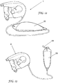
Figure 1 shows a pump head for use in a hand-held peristaltic pump apparatus in accordance with an embodiment of the invention; -
Figure 2 illustrates the pump head ofFigure 1 in use; -
Figure 3 shows an embodiment of a hand-held peristaltic pump apparatus in accordance with an embodiment of the invention; -
Figure 4 is an exploded view of the pump head ofFigure 1 ; -
Figure 5 shows another embodiment of a pump apparatus in accordance with the invention, in a storage configuration; -
Figure 6 shows the pump apparatus ofFigure 5 in use, and alternative embodiments of container for use in the pump apparatus; -
Figure 7 illustrates the pump apparatus ofFigure 5 in a sterile, packaged condition; -
Figure 8 shows the valve location in an embodiment of the pump apparatus; -
Figures 9-11 illustrate the non-return valve arrangement of pump apparatus in accordance with an embodiment of the invention; -
Figures 12-14 illustrate further embodiments of a pump apparatus in accordance with the invention; -
Figure 15 shows hooks for use with the embodiments ofFigures 12-14 ; and -
Figures 16-18 show pump apparatus in accordance with a further embodiment of the invention. - Referring to
Figure 1 , apump head 2 houses a rotatableperistaltic pump member 6 and aflexible dispensing tube 4 disposed through thepump head 2. Thepump head 2 includes a finger-actuatedtrigger 12 which is provided with at least onepawl member 52. Actuation of thetrigger 12 causes turning of thepump member 6 in one direction only, by interaction between thepawl member 52 and ratchet features 50 on thepump member 6. At least one impeller 36 (best shown inFigure 4 ) acts on thedispensing tube 4 to squeeze thetube 4 against an inner surface of the pump head. As thepump member 6 turns, theimpeller 36 drives fluid ahead of it through the dispensing tube and out through anozzle 10. - The volume squeezed out by the
impeller 36 is independent of the viscosity of the fluid within the dispensingtube 4 Thedispensing tube 4 is elastomeric, at least in the region where theimpeller 36 acts upon it, to ensure that the tube returns to its original cross-sectional shape when not acted upon by an impeller. In a preferred embodiment, the dispensingtube 4 is elastomeric along its entire length. In this embodiment, the dispensingtube 4 is of a unitary construction and formed from a silicone rubber. - The
pump head 2 is provided with athumb hole 8 disposed within an area around which theperistaltic pump member 6 turns when actuated. This arrangement permits a user'shand 14 to grip thepump head 2 by locating thethumb 16 in thethumb hole 8 and all the user's fingers18 on thetrigger 12. This has the benefit that no part of a user's finger will be trapped between thetrigger 12 and the housing (22,24) of the pump head 2 (Figure 4 ). Such trapping can cause tearing of a user's glove and contamination of a sterile or clean-room environment in which the pump head is being used, as well as potential finger damage. The arrangement allows the pump head to be of sufficient size to accommodate a rotary peristaltic pump member of a large enough diameter not to cause kinking or flattening of the dispensing tube as a result of its conforming to the curvature of the pump member. Location of all fingers on thetrigger 12 is also ergonomic and helps reduce RSI from repeated trigger actuation compared to a conventional trigger sprayer in which not all fingers act on the trigger. In this example, the thumb hole has a central axis which is substantially coincident with an axis of rotation of theperistaltic pump member 6. - An embodiment of a hand-held
peristaltic pump apparatus 1 shown inFigure 3 includes arigid container 20 attached to thepump head 2 and containing a liquid to be dispensed. Thedispensing tube 4 is in fluid connection with the liquid and will be dispensed through thenozzle 10 when the user squeezes the trigger. - Referring now to
Figure 4 , the exemplifiedpump head 2 is assembled fromopposed parts trigger 12 is pivotally mounted and biased by areturn spring 26. The peristaltic pump member is formed fromopposed drive wheels impellers 36 and rotatably mounted within the pump housing. Thedispensing tube 4 is disposed around the pump member and connected at one end to thenozzle 10 via aconnector 30 and at the other end to asupply tube 28 as will be further described in more detail presently. The dispensingtube 4 fits securely around theconnector 30, which co-operates with thenozzle 10 to provide a nozzle assembly. Sealing of the nozzle assembly in the pump head is achieved by means of thedispensing tube 4, which is preferably formed of a silicone rubber. Sealing of the nozzle assembly in the pump head is also achieved by means of the dispensingtube 4. In this example the final seal is ultrasonically welded once thesupply tube 28 has been connected. It will be appreciated that other methods may be used to achieve the final seal; suitable methods will be known to those skilled in the art. - The
container 20 need not be rigidly connected to thepump head 2. Indeed, it is preferred that thecontainer 20 is connected to thepump head 2 only by the dispensingtube 4 and optionally via thesupply tube 28. This allows the container to be supported by means other than the user holding it and relieves the user from carrying the weight of the container. Referring toFigure 5 , thecontainer 20 is a collapsible bag and is provided with a feature 42 to enable it to be hung from a bar orother support structure 40. The exemplified feature 42 is a hole through which ahook 44 passes. Thepump head 2 may also be hung up when not in use, for example by means of ahook 38 through thethumb hole 8. - When the pump apparatus is in use the
tubing 28 connecting thecontainer 20 to thepump head 2 allows the user to carry out fluid pumping operations some distance from the container, which may be supported in various ways. Referring toFigure 6 , thetubing 28 is shown fully extended and may have may have any desired length, for example a length in the range 1-3 metres, preferably about 1.5 m.Containers 20 of different capacity may be used, as illustrated in the left hand and centre representations ofFigure 6 which have, respectively, 1 litre and 3 litre capacities. The proximal end of thesupply tube 28 is located inside thecontainer 20 and in fluid contact with liquid therein. Adjacent to thedistal end 48 of thesupply tube 28, the wall of the supply tube has ahole 46 extending all the way through the wall. - When the
pump apparatus 1 is to be used in a sterile environment, it is triplebagged 54 and gamma-irradiated to kill any pathogens. The process of gammairradiation causes liquid in thecontainer 20 to heat up substantially, for example to about 55°C, which creates an internal pressure. To release this pressure, a non-return valve is required, and in this example is provided in the overlap of thesupply tube 28 and the dispensingtube 4 inside thepump head 2 by aninterference detail 56 indicated inFigure 8 . - Referring now to
Figures 9-11 , the non-return valve arrangement formed by connection of the dispensingtube 4 andsupply tube 28 is shown. In this example the supply tube is made of PVC and the dispensing tube is made of a silicone rubber. Thedistal end 48 of thesupply tube 28 is disposed within and is a close fit for the dispensingtube 4. Thehole 46 is also within the dispensingtube 4. Theinterference detail 56 clamps the dispensingtube 4 to thesupply tube 28 within thepump head 2, but thehole 46 is not clamped so is free to release. When pressure is applied from the supply tube 28 (Figure 10 ) from theliquid container 20 the dispensing tube stretches away from thehole 46 allowing gas to flow out and relieve the pressure. When the liquid in the container cools down and the pressure is reversed (Figure 11 ) the rubber wall of the dispensing tube is sucked over thehole 46 and creates a seal. Thus, the dispensing tube provides a seal over the hole to prevent ingress of fluid when the internal pressure in the container is lower than the external (atmospheric) pressure. - This arrangement avoids the need for a separate vent tube and provides a pump apparatus of simplified construction.
- The
container 20 may be placed on the ground (Figure 12 ) while in use, or hung from a hook 44 (Figure 13 ) from which thepump head 2 may also be hung when not in use (Figure 14 ). Thehook 44 may be provided with asuction cup 56 for attachment to any suitable smooth surface; thehook 44 may be pivotable between an attaching position and an attached position, shown in the left and right representations respectively ofFigure 15 . - In the embodiment shown in
Figures 16-18 thecontainer 20 is collapsible and is housed in a substantiallyrigid container housing 64, in this example a flagon. Thecontainer 20 is placed in the flagon through anopening 62 and thesupply tube 28 in this example is disposed through a hole at the base of the flagon. Theflagon 64 has a mouldedfeature 58 which provides a seat for thepump head 2 when not in use. In this example thefeature 58 is provided in acap 60 which covers theopening 62. - It is envisaged that the
pump head 2 andcontainer housing 64 will be reused, and thecontainer 20 is a refill component which will be replaced as needed. - It will be understood that the
container 20 andsupply tube 28 may be manufactured and sold independently of the pump head, . Accordingly, another aspect of the invention provides a container specified. Although the invention has been illustrated with respect to a hand-held peristaltic pump head of a particular design, it will be understood that the invention is not limited to this embodiment and the pump head may take any conventional form, notably one in which the dispensing tube is sealed when not in use. - It is appreciated that certain features of the invention, which are, for clarity, described in the context of separate embodiments, may also be provided in combination in a single embodiment. Conversely, various features of the invention which are, for brevity, described in the context of a single embodiment, may also be provided separately, or in any suitable combination.
Claims (11)
- A pump apparatus (1) comprising a pump head (2) and a container (20) for a liquid to be dispensed;
the pump head (2) having a flexible dispensing tube (4) in fluid connection with the inside of the container (20);
the fluid connection between the dispensing tube (4) and the inside of the container (20) being provided by a supply tube (28) which co-operates with the dispensing tube (4) to provide a non-return valve function;
wherein an end (48) of the supply tube (28) is disposed within an end of the dispensing tube (4) and characterised in that
the non-return valve function is provided by a hole (46) through a side wall of the supply tube (28) in a region where the dispensing tube (4) overlaps the supply tube (28), whereby the dispensing tube (4) provides a seal over the hole (46) to prevent ingress of fluid when the internal pressure is lower than the external pressure. - Pump apparatus according to claim 1, wherein the dispensing tube (4) is formed of silicone rubber.
- Pump apparatus according to claim 1 or claim 2, wherein the length of the tubing which connects the pump head (2) to the container (20) is in the range 1-3 metres.
- Pump apparatus according to any preceding claim, wherein the container (20) is provided with a feature to enable it to be hung from a support structure (44).
- Pump apparatus according to claim 4, wherein said feature is a hole or a hook.
- Pump apparatus according to any preceding claim, wherein the container (20) is collapsible and is housed in a substantially rigid container housing (64).
- Pump apparatus according to claim 6, wherein the container housing (64) is provided with a seat (58) for receiving the pump head (2) when not in use.
- Pump apparatus according to any preceding claim, wherein the pump head (2) has means for sealing the supply tube when not dispensing liquid.
- Pump apparatus according to any preceding claim, wherein the pump head (2) is a peristaltic pump head.
- Pump apparatus according to any preceding claim, the pump head (2) having a nozzle (10); wherein sealing of the nozzle (10) is provided by engagement between the dispensing tube (4) and the nozzle (10).
- A method of sterilizing a pump apparatus according to any preceding claim, having a liquid in the container (20), the method comprising irradiating the apparatus with gamma radiation and permitting gas pressure generated by heating of the liquid to be reduced by escape of gas through the non-return valve function.
Priority Applications (1)
| Application Number | Priority Date | Filing Date | Title |
|---|---|---|---|
| SI201330536A SI2911802T1 (en) | 2012-10-25 | 2013-07-31 | Pump apparatus |
Applications Claiming Priority (2)
| Application Number | Priority Date | Filing Date | Title |
|---|---|---|---|
| GB1219218.3A GB2507313B (en) | 2012-10-25 | 2012-10-25 | Pump apparatus |
| PCT/GB2013/052047 WO2014064415A1 (en) | 2012-10-25 | 2013-07-31 | Pump apparatus |
Publications (2)
| Publication Number | Publication Date |
|---|---|
| EP2911802A1 EP2911802A1 (en) | 2015-09-02 |
| EP2911802B1 true EP2911802B1 (en) | 2017-02-01 |
Family
ID=47358650
Family Applications (1)
| Application Number | Title | Priority Date | Filing Date |
|---|---|---|---|
| EP13756661.8A Active EP2911802B1 (en) | 2012-10-25 | 2013-07-31 | Pump apparatus |
Country Status (22)
| Country | Link |
|---|---|
| US (1) | US9790939B2 (en) |
| EP (1) | EP2911802B1 (en) |
| JP (1) | JP6155341B2 (en) |
| KR (1) | KR102042205B1 (en) |
| CN (1) | CN104797347B (en) |
| AU (1) | AU2013336401B2 (en) |
| BR (1) | BR112015009115B1 (en) |
| CA (1) | CA2884961C (en) |
| DK (1) | DK2911802T3 (en) |
| ES (1) | ES2616493T3 (en) |
| GB (1) | GB2507313B (en) |
| HK (1) | HK1208200A1 (en) |
| IL (1) | IL237896B (en) |
| MX (1) | MX357952B (en) |
| MY (1) | MY184217A (en) |
| NZ (1) | NZ705905A (en) |
| PT (1) | PT2911802T (en) |
| RU (1) | RU2621763C2 (en) |
| SG (1) | SG11201501942SA (en) |
| SI (1) | SI2911802T1 (en) |
| WO (1) | WO2014064415A1 (en) |
| ZA (1) | ZA201501783B (en) |
Citations (3)
| Publication number | Priority date | Publication date | Assignee | Title |
|---|---|---|---|---|
| US4159790A (en) * | 1977-12-19 | 1979-07-03 | Bailey Vincent R | Dispensing container |
| US6505986B1 (en) * | 1997-11-21 | 2003-01-14 | The Procter & Gamble Company | Applicator systems |
| US20070119875A1 (en) * | 2005-01-27 | 2007-05-31 | Vincent Ehret | Volumetric displacement dispenser |
Family Cites Families (40)
| Publication number | Priority date | Publication date | Assignee | Title |
|---|---|---|---|---|
| US424944A (en) | 1890-04-08 | Instrument for the transfusion of blood | ||
| US2018999A (en) | 1934-10-11 | 1935-10-29 | George D Lilly | Surgical pump |
| US2275937A (en) * | 1941-01-11 | 1942-03-10 | Baker Oil Tools Inc | Cementing device for well casings |
| US2527614A (en) | 1948-01-29 | 1950-10-31 | Arpin John William | Water pistol |
| US3248022A (en) * | 1963-06-21 | 1966-04-26 | Valve Corp Of America | Atomizer pump |
| US3674024A (en) | 1970-07-15 | 1972-07-04 | Kidde & Co Walter | Incision irrigator for use during surgical procedures |
| US3786683A (en) | 1972-09-12 | 1974-01-22 | Alphamedics Mfg Corp | Hand-operated pipette |
| US3930761A (en) * | 1972-12-19 | 1976-01-06 | The Boots Company, Ltd. | Portable and manually operable peristaltic pump |
| US4070725A (en) * | 1975-11-07 | 1978-01-31 | Cornelius Eng | Combined pump and siphon |
| US4205948A (en) | 1977-02-10 | 1980-06-03 | Jones Allan R | Peristaltic pump |
| US4232828A (en) | 1977-11-28 | 1980-11-11 | Shelly Jr Newton L | Hand held liquid spray head with removable liquid conduit |
| US4214681A (en) | 1978-09-22 | 1980-07-29 | Levine Abraham I | Applicating device |
| US4249676A (en) * | 1979-05-31 | 1981-02-10 | Hallmark Cards Incorporated | Air vent check valve |
| US4515589A (en) * | 1981-03-23 | 1985-05-07 | Austin Jon W | Peristaltic pumping method and apparatus |
| US4722731A (en) * | 1985-04-08 | 1988-02-02 | Vailancourt Vincent L | Air check valve |
| US4885818A (en) | 1988-07-15 | 1989-12-12 | Arterbury Travis W | Ergonomic knife and knife handle |
| US4892526A (en) * | 1988-08-18 | 1990-01-09 | Reese H William | Surgical irrigation apparatus |
| US5260062A (en) * | 1988-12-29 | 1993-11-09 | Colgate-Palmolive Company | Anti-plaque and anti-tartar dentifrices in plastic pump dispensers |
| NL9400346A (en) * | 1994-03-07 | 1995-10-02 | Itsac Nv | Liquid dispenser with refill pack. |
| KR970062448A (en) * | 1996-02-28 | 1997-09-12 | 김광호 | Backflow prevention device |
| WO1998052863A1 (en) * | 1997-05-21 | 1998-11-26 | Fleit, Lois | Novel liquid dispensing device and method of making same |
| US6000633A (en) * | 1998-03-31 | 1999-12-14 | The Proctor & Gamble Company | Spray nozzle for anti-clog spray package |
| EP1020233A1 (en) * | 1999-01-13 | 2000-07-19 | The Procter & Gamble Company | Dosing and delivering system |
| US6293762B1 (en) * | 1999-04-22 | 2001-09-25 | Hormoz Farkhan | Methods for sealing a tire and for introducing liquid into a tire |
| IT1307523B1 (en) * | 1999-12-02 | 2001-11-06 | Taplast Spa | METHOD OF DISPENSING LIQUIDS IN THE FORM OF FOAM THROUGH DEFORMABLE CONTAINERS AND DEVICE USING SUCH METHOD |
| RU2185983C2 (en) * | 2000-05-10 | 2002-07-27 | Открытое акционерное общество "Брянский машиностроительный завод" | Locomotive three-axle bogie |
| GB0118649D0 (en) * | 2001-07-31 | 2001-09-19 | Unilever Plc | Dispensing device |
| JP3759735B2 (en) * | 2003-05-12 | 2006-03-29 | 三矢メディカル株式会社 | Medical check valve |
| JP2006159004A (en) | 2004-12-02 | 2006-06-22 | Canyon Corp | Pump dispenser |
| FR2885890B1 (en) * | 2005-05-20 | 2007-07-20 | Rexam Dispensing Systems Sas | DEVICE FOR DELIVERING AND ADMITTING A LIQUID PRODUCT |
| EP1911525B1 (en) * | 2005-07-29 | 2012-04-11 | Yoshino Kogyosho Co., Ltd. | Ejecting container |
| WO2007086156A1 (en) * | 2006-01-26 | 2007-08-02 | Mitani Valve Co., Ltd. | Content discharge mechanism for pump-type container and pump-type product with content discharge mechanism |
| GB0620857D0 (en) | 2006-10-20 | 2006-11-29 | Johnson Electric Sa | Steam cleaning appliance and pump |
| EP2087238A4 (en) * | 2006-11-16 | 2017-03-22 | Nestec S.A. | Metering pump for dispensing liquid |
| TWI346634B (en) * | 2007-05-18 | 2011-08-11 | Sikorsky Aircraft Corp | Engine anticipation for rotary wing aircraft |
| ITMI20071936A1 (en) * | 2007-10-08 | 2008-01-07 | Lumson Spa | METHOD FOR THE REALIZATION OF A DEVICE TO INCLUDE AIR HOLD AND TO SUPPLY FLUID SUBSTANCES AND DEVICE SO IT IS OBTAINED |
| US8591532B2 (en) * | 2008-02-12 | 2013-11-26 | Ethicon Endo-Sugery, Inc. | Automatically adjusting band system |
| US8272857B2 (en) * | 2008-02-22 | 2012-09-25 | Medtronic Xomed, Inc. | Method and system for loading of tubing into a pumping device |
| US8337466B2 (en) | 2009-03-30 | 2012-12-25 | Lifemedix, Llc | Manual pump for intravenous fluids |
| US20120223161A1 (en) * | 2011-03-01 | 2012-09-06 | Smg Brands, Inc. | Ready-to-use hose end sprayer |
-
2012
- 2012-10-25 GB GB1219218.3A patent/GB2507313B/en active Active
-
2013
- 2013-07-31 SG SG11201501942SA patent/SG11201501942SA/en unknown
- 2013-07-31 US US14/432,644 patent/US9790939B2/en active Active
- 2013-07-31 EP EP13756661.8A patent/EP2911802B1/en active Active
- 2013-07-31 RU RU2015109867A patent/RU2621763C2/en active
- 2013-07-31 JP JP2015538556A patent/JP6155341B2/en not_active Expired - Fee Related
- 2013-07-31 PT PT137566618T patent/PT2911802T/en unknown
- 2013-07-31 ES ES13756661.8T patent/ES2616493T3/en active Active
- 2013-07-31 BR BR112015009115-6A patent/BR112015009115B1/en not_active IP Right Cessation
- 2013-07-31 AU AU2013336401A patent/AU2013336401B2/en not_active Ceased
- 2013-07-31 CA CA2884961A patent/CA2884961C/en not_active Expired - Fee Related
- 2013-07-31 DK DK13756661.8T patent/DK2911802T3/en active
- 2013-07-31 MX MX2015005095A patent/MX357952B/en active IP Right Grant
- 2013-07-31 MY MYPI2015701177A patent/MY184217A/en unknown
- 2013-07-31 SI SI201330536A patent/SI2911802T1/en unknown
- 2013-07-31 WO PCT/GB2013/052047 patent/WO2014064415A1/en active Application Filing
- 2013-07-31 NZ NZ705905A patent/NZ705905A/en not_active IP Right Cessation
- 2013-07-31 CN CN201380054333.6A patent/CN104797347B/en not_active Expired - Fee Related
- 2013-07-31 KR KR1020157010455A patent/KR102042205B1/en active IP Right Grant
-
2015
- 2015-03-16 ZA ZA2015/01783A patent/ZA201501783B/en unknown
- 2015-03-23 IL IL237896A patent/IL237896B/en active IP Right Grant
- 2015-09-14 HK HK15108954.0A patent/HK1208200A1/en not_active IP Right Cessation
Patent Citations (3)
| Publication number | Priority date | Publication date | Assignee | Title |
|---|---|---|---|---|
| US4159790A (en) * | 1977-12-19 | 1979-07-03 | Bailey Vincent R | Dispensing container |
| US6505986B1 (en) * | 1997-11-21 | 2003-01-14 | The Procter & Gamble Company | Applicator systems |
| US20070119875A1 (en) * | 2005-01-27 | 2007-05-31 | Vincent Ehret | Volumetric displacement dispenser |
Also Published As
| Publication number | Publication date |
|---|---|
| AU2013336401B2 (en) | 2017-03-09 |
| SI2911802T1 (en) | 2017-04-26 |
| DK2911802T3 (en) | 2017-02-27 |
| HK1208200A1 (en) | 2016-02-26 |
| MX2015005095A (en) | 2015-07-17 |
| KR20150077419A (en) | 2015-07-07 |
| US20150233360A1 (en) | 2015-08-20 |
| IL237896B (en) | 2018-06-28 |
| CA2884961C (en) | 2020-04-07 |
| GB201219218D0 (en) | 2012-12-12 |
| RU2621763C2 (en) | 2017-06-07 |
| BR112015009115B1 (en) | 2020-11-24 |
| CN104797347A (en) | 2015-07-22 |
| ZA201501783B (en) | 2016-10-26 |
| WO2014064415A1 (en) | 2014-05-01 |
| ES2616493T3 (en) | 2017-06-13 |
| GB2507313A (en) | 2014-04-30 |
| BR112015009115A2 (en) | 2017-07-04 |
| NZ705905A (en) | 2016-10-28 |
| MY184217A (en) | 2021-03-26 |
| AU2013336401A1 (en) | 2015-04-02 |
| EP2911802A1 (en) | 2015-09-02 |
| CA2884961A1 (en) | 2014-05-01 |
| PT2911802T (en) | 2017-02-22 |
| JP6155341B2 (en) | 2017-06-28 |
| US9790939B2 (en) | 2017-10-17 |
| SG11201501942SA (en) | 2015-04-29 |
| RU2015109867A (en) | 2016-12-20 |
| CN104797347B (en) | 2017-10-31 |
| MX357952B (en) | 2018-07-31 |
| JP2016502455A (en) | 2016-01-28 |
| KR102042205B1 (en) | 2019-11-07 |
| GB2507313B (en) | 2015-09-30 |
Similar Documents
| Publication | Publication Date | Title |
|---|---|---|
| EP2911801B1 (en) | Hand-held pump apparatus | |
| US8453885B2 (en) | Hand held peristaltic pump for dispensing fluid from a rigid container | |
| ES2637201T3 (en) | Liquid distribution device supplied with a drip valve system | |
| EP2911802B1 (en) | Pump apparatus | |
| SE501000C2 (en) | Liquid substance dispensing device | |
| GB2518854A (en) | A nozzle head |
Legal Events
| Date | Code | Title | Description |
|---|---|---|---|
| PUAI | Public reference made under article 153(3) epc to a published international application that has entered the european phase |
Free format text: ORIGINAL CODE: 0009012 |
|
| 17P | Request for examination filed |
Effective date: 20150313 |
|
| AK | Designated contracting states |
Kind code of ref document: A1 Designated state(s): AL AT BE BG CH CY CZ DE DK EE ES FI FR GB GR HR HU IE IS IT LI LT LU LV MC MK MT NL NO PL PT RO RS SE SI SK SM TR |
|
| AX | Request for extension of the european patent |
Extension state: BA ME |
|
| 17Q | First examination report despatched |
Effective date: 20151204 |
|
| DAX | Request for extension of the european patent (deleted) | ||
| REG | Reference to a national code |
Ref country code: HK Ref legal event code: DE Ref document number: 1208200 Country of ref document: HK |
|
| GRAP | Despatch of communication of intention to grant a patent |
Free format text: ORIGINAL CODE: EPIDOSNIGR1 |
|
| INTG | Intention to grant announced |
Effective date: 20160915 |
|
| GRAS | Grant fee paid |
Free format text: ORIGINAL CODE: EPIDOSNIGR3 |
|
| GRAA | (expected) grant |
Free format text: ORIGINAL CODE: 0009210 |
|
| AK | Designated contracting states |
Kind code of ref document: B1 Designated state(s): AL AT BE BG CH CY CZ DE DK EE ES FI FR GB GR HR HU IE IS IT LI LT LU LV MC MK MT NL NO PL PT RO RS SE SI SK SM TR |
|
| REG | Reference to a national code |
Ref country code: GB Ref legal event code: FG4D |
|
| REG | Reference to a national code |
Ref country code: CH Ref legal event code: EP Ref country code: CH Ref legal event code: NV Representative=s name: MICHELI AND CIE SA, CH Ref country code: AT Ref legal event code: REF Ref document number: 865095 Country of ref document: AT Kind code of ref document: T Effective date: 20170215 |
|
| REG | Reference to a national code |
Ref country code: RO Ref legal event code: EPE |
|
| REG | Reference to a national code |
Ref country code: IE Ref legal event code: FG4D Ref country code: PT Ref legal event code: SC4A Ref document number: 2911802 Country of ref document: PT Date of ref document: 20170222 Kind code of ref document: T Free format text: AVAILABILITY OF NATIONAL TRANSLATION Effective date: 20170216 |
|
| REG | Reference to a national code |
Ref country code: DK Ref legal event code: T3 Effective date: 20170220 |
|
| REG | Reference to a national code |
Ref country code: SE Ref legal event code: TRGR |
|
| REG | Reference to a national code |
Ref country code: DE Ref legal event code: R096 Ref document number: 602013017054 Country of ref document: DE |
|
| REG | Reference to a national code |
Ref country code: NL Ref legal event code: FP |
|
| REG | Reference to a national code |
Ref country code: FR Ref legal event code: PLFP Year of fee payment: 5 |
|
| REG | Reference to a national code |
Ref country code: LT Ref legal event code: MG4D |
|
| REG | Reference to a national code |
Ref country code: ES Ref legal event code: FG2A Ref document number: 2616493 Country of ref document: ES Kind code of ref document: T3 Effective date: 20170613 |
|
| PG25 | Lapsed in a contracting state [announced via postgrant information from national office to epo] |
Ref country code: HR Free format text: LAPSE BECAUSE OF FAILURE TO SUBMIT A TRANSLATION OF THE DESCRIPTION OR TO PAY THE FEE WITHIN THE PRESCRIBED TIME-LIMIT Effective date: 20170201 Ref country code: IS Free format text: LAPSE BECAUSE OF FAILURE TO SUBMIT A TRANSLATION OF THE DESCRIPTION OR TO PAY THE FEE WITHIN THE PRESCRIBED TIME-LIMIT Effective date: 20170601 Ref country code: LT Free format text: LAPSE BECAUSE OF FAILURE TO SUBMIT A TRANSLATION OF THE DESCRIPTION OR TO PAY THE FEE WITHIN THE PRESCRIBED TIME-LIMIT Effective date: 20170201 Ref country code: NO Free format text: LAPSE BECAUSE OF FAILURE TO SUBMIT A TRANSLATION OF THE DESCRIPTION OR TO PAY THE FEE WITHIN THE PRESCRIBED TIME-LIMIT Effective date: 20170501 |
|
| PG25 | Lapsed in a contracting state [announced via postgrant information from national office to epo] |
Ref country code: PL Free format text: LAPSE BECAUSE OF FAILURE TO SUBMIT A TRANSLATION OF THE DESCRIPTION OR TO PAY THE FEE WITHIN THE PRESCRIBED TIME-LIMIT Effective date: 20170201 Ref country code: BG Free format text: LAPSE BECAUSE OF FAILURE TO SUBMIT A TRANSLATION OF THE DESCRIPTION OR TO PAY THE FEE WITHIN THE PRESCRIBED TIME-LIMIT Effective date: 20170501 Ref country code: RS Free format text: LAPSE BECAUSE OF FAILURE TO SUBMIT A TRANSLATION OF THE DESCRIPTION OR TO PAY THE FEE WITHIN THE PRESCRIBED TIME-LIMIT Effective date: 20170201 Ref country code: LV Free format text: LAPSE BECAUSE OF FAILURE TO SUBMIT A TRANSLATION OF THE DESCRIPTION OR TO PAY THE FEE WITHIN THE PRESCRIBED TIME-LIMIT Effective date: 20170201 |
|
| PG25 | Lapsed in a contracting state [announced via postgrant information from national office to epo] |
Ref country code: SK Free format text: LAPSE BECAUSE OF FAILURE TO SUBMIT A TRANSLATION OF THE DESCRIPTION OR TO PAY THE FEE WITHIN THE PRESCRIBED TIME-LIMIT Effective date: 20170201 Ref country code: CZ Free format text: LAPSE BECAUSE OF FAILURE TO SUBMIT A TRANSLATION OF THE DESCRIPTION OR TO PAY THE FEE WITHIN THE PRESCRIBED TIME-LIMIT Effective date: 20170201 Ref country code: EE Free format text: LAPSE BECAUSE OF FAILURE TO SUBMIT A TRANSLATION OF THE DESCRIPTION OR TO PAY THE FEE WITHIN THE PRESCRIBED TIME-LIMIT Effective date: 20170201 |
|
| REG | Reference to a national code |
Ref country code: DE Ref legal event code: R097 Ref document number: 602013017054 Country of ref document: DE |
|
| PG25 | Lapsed in a contracting state [announced via postgrant information from national office to epo] |
Ref country code: SM Free format text: LAPSE BECAUSE OF FAILURE TO SUBMIT A TRANSLATION OF THE DESCRIPTION OR TO PAY THE FEE WITHIN THE PRESCRIBED TIME-LIMIT Effective date: 20170201 |
|
| PLBE | No opposition filed within time limit |
Free format text: ORIGINAL CODE: 0009261 |
|
| STAA | Information on the status of an ep patent application or granted ep patent |
Free format text: STATUS: NO OPPOSITION FILED WITHIN TIME LIMIT |
|
| REG | Reference to a national code |
Ref country code: HK Ref legal event code: GR Ref document number: 1208200 Country of ref document: HK |
|
| 26N | No opposition filed |
Effective date: 20171103 |
|
| REG | Reference to a national code |
Ref country code: FR Ref legal event code: PLFP Year of fee payment: 6 |
|
| PG25 | Lapsed in a contracting state [announced via postgrant information from national office to epo] |
Ref country code: MT Free format text: LAPSE BECAUSE OF NON-PAYMENT OF DUE FEES Effective date: 20170731 |
|
| REG | Reference to a national code |
Ref country code: AT Ref legal event code: UEP Ref document number: 865095 Country of ref document: AT Kind code of ref document: T Effective date: 20170201 |
|
| PG25 | Lapsed in a contracting state [announced via postgrant information from national office to epo] |
Ref country code: MC Free format text: LAPSE BECAUSE OF FAILURE TO SUBMIT A TRANSLATION OF THE DESCRIPTION OR TO PAY THE FEE WITHIN THE PRESCRIBED TIME-LIMIT Effective date: 20170201 Ref country code: HU Free format text: LAPSE BECAUSE OF FAILURE TO SUBMIT A TRANSLATION OF THE DESCRIPTION OR TO PAY THE FEE WITHIN THE PRESCRIBED TIME-LIMIT; INVALID AB INITIO Effective date: 20130731 |
|
| PG25 | Lapsed in a contracting state [announced via postgrant information from national office to epo] |
Ref country code: CY Free format text: LAPSE BECAUSE OF FAILURE TO SUBMIT A TRANSLATION OF THE DESCRIPTION OR TO PAY THE FEE WITHIN THE PRESCRIBED TIME-LIMIT Effective date: 20170201 |
|
| PG25 | Lapsed in a contracting state [announced via postgrant information from national office to epo] |
Ref country code: MK Free format text: LAPSE BECAUSE OF FAILURE TO SUBMIT A TRANSLATION OF THE DESCRIPTION OR TO PAY THE FEE WITHIN THE PRESCRIBED TIME-LIMIT Effective date: 20170201 |
|
| PG25 | Lapsed in a contracting state [announced via postgrant information from national office to epo] |
Ref country code: AL Free format text: LAPSE BECAUSE OF FAILURE TO SUBMIT A TRANSLATION OF THE DESCRIPTION OR TO PAY THE FEE WITHIN THE PRESCRIBED TIME-LIMIT Effective date: 20170201 |
|
| PGFP | Annual fee paid to national office [announced via postgrant information from national office to epo] |
Ref country code: PT Payment date: 20200618 Year of fee payment: 8 Ref country code: FI Payment date: 20200523 Year of fee payment: 8 Ref country code: RO Payment date: 20200630 Year of fee payment: 8 Ref country code: DK Payment date: 20200515 Year of fee payment: 8 Ref country code: GR Payment date: 20200515 Year of fee payment: 8 Ref country code: TR Payment date: 20200515 Year of fee payment: 8 |
|
| PGFP | Annual fee paid to national office [announced via postgrant information from national office to epo] |
Ref country code: SE Payment date: 20200523 Year of fee payment: 8 |
|
| PGFP | Annual fee paid to national office [announced via postgrant information from national office to epo] |
Ref country code: NL Payment date: 20200709 Year of fee payment: 8 |
|
| PGFP | Annual fee paid to national office [announced via postgrant information from national office to epo] |
Ref country code: ES Payment date: 20200806 Year of fee payment: 8 Ref country code: LU Payment date: 20200721 Year of fee payment: 8 |
|
| PGFP | Annual fee paid to national office [announced via postgrant information from national office to epo] |
Ref country code: IT Payment date: 20200723 Year of fee payment: 8 Ref country code: CH Payment date: 20200717 Year of fee payment: 8 Ref country code: SI Payment date: 20200629 Year of fee payment: 8 |
|
| PGFP | Annual fee paid to national office [announced via postgrant information from national office to epo] |
Ref country code: FR Payment date: 20210628 Year of fee payment: 9 |
|
| PGFP | Annual fee paid to national office [announced via postgrant information from national office to epo] |
Ref country code: BE Payment date: 20210625 Year of fee payment: 9 Ref country code: GB Payment date: 20210624 Year of fee payment: 9 |
|
| PGFP | Annual fee paid to national office [announced via postgrant information from national office to epo] |
Ref country code: AT Payment date: 20210721 Year of fee payment: 9 Ref country code: IE Payment date: 20210705 Year of fee payment: 9 |
|
| PGFP | Annual fee paid to national office [announced via postgrant information from national office to epo] |
Ref country code: DE Payment date: 20210626 Year of fee payment: 9 |
|
| REG | Reference to a national code |
Ref country code: DK Ref legal event code: EBP Effective date: 20210731 |
|
| REG | Reference to a national code |
Ref country code: FI Ref legal event code: MAE Ref country code: CH Ref legal event code: PL |
|
| REG | Reference to a national code |
Ref country code: NL Ref legal event code: MM Effective date: 20210801 |
|
| REG | Reference to a national code |
Ref country code: SE Ref legal event code: EUG |
|
| PG25 | Lapsed in a contracting state [announced via postgrant information from national office to epo] |
Ref country code: LI Free format text: LAPSE BECAUSE OF NON-PAYMENT OF DUE FEES Effective date: 20210731 Ref country code: FI Free format text: LAPSE BECAUSE OF NON-PAYMENT OF DUE FEES Effective date: 20210731 Ref country code: CH Free format text: LAPSE BECAUSE OF NON-PAYMENT OF DUE FEES Effective date: 20210731 |
|
| PG25 | Lapsed in a contracting state [announced via postgrant information from national office to epo] |
Ref country code: SE Free format text: LAPSE BECAUSE OF NON-PAYMENT OF DUE FEES Effective date: 20210801 Ref country code: RO Free format text: LAPSE BECAUSE OF NON-PAYMENT OF DUE FEES Effective date: 20210731 Ref country code: PT Free format text: LAPSE BECAUSE OF NON-PAYMENT OF DUE FEES Effective date: 20220131 Ref country code: NL Free format text: LAPSE BECAUSE OF NON-PAYMENT OF DUE FEES Effective date: 20210801 Ref country code: LU Free format text: LAPSE BECAUSE OF NON-PAYMENT OF DUE FEES Effective date: 20210731 Ref country code: GR Free format text: LAPSE BECAUSE OF NON-PAYMENT OF DUE FEES Effective date: 20220207 |
|
| PG25 | Lapsed in a contracting state [announced via postgrant information from national office to epo] |
Ref country code: TR Free format text: LAPSE BECAUSE OF NON-PAYMENT OF DUE FEES Effective date: 20210731 |
|
| PG25 | Lapsed in a contracting state [announced via postgrant information from national office to epo] |
Ref country code: IT Free format text: LAPSE BECAUSE OF NON-PAYMENT OF DUE FEES Effective date: 20210731 Ref country code: DK Free format text: LAPSE BECAUSE OF NON-PAYMENT OF DUE FEES Effective date: 20210731 |
|
| REG | Reference to a national code |
Ref country code: ES Ref legal event code: FD2A Effective date: 20221026 |
|
| PG25 | Lapsed in a contracting state [announced via postgrant information from national office to epo] |
Ref country code: ES Free format text: LAPSE BECAUSE OF NON-PAYMENT OF DUE FEES Effective date: 20210801 |
|
| REG | Reference to a national code |
Ref country code: DE Ref legal event code: R119 Ref document number: 602013017054 Country of ref document: DE |
|
| REG | Reference to a national code |
Ref country code: AT Ref legal event code: MM01 Ref document number: 865095 Country of ref document: AT Kind code of ref document: T Effective date: 20220731 |
|
| GBPC | Gb: european patent ceased through non-payment of renewal fee |
Effective date: 20220731 |
|
| REG | Reference to a national code |
Ref country code: BE Ref legal event code: MM Effective date: 20220731 |
|
| PG25 | Lapsed in a contracting state [announced via postgrant information from national office to epo] |
Ref country code: FR Free format text: LAPSE BECAUSE OF NON-PAYMENT OF DUE FEES Effective date: 20220731 Ref country code: AT Free format text: LAPSE BECAUSE OF NON-PAYMENT OF DUE FEES Effective date: 20220731 |
|
| PG25 | Lapsed in a contracting state [announced via postgrant information from national office to epo] |
Ref country code: GB Free format text: LAPSE BECAUSE OF NON-PAYMENT OF DUE FEES Effective date: 20220731 Ref country code: DE Free format text: LAPSE BECAUSE OF NON-PAYMENT OF DUE FEES Effective date: 20230201 Ref country code: BE Free format text: LAPSE BECAUSE OF NON-PAYMENT OF DUE FEES Effective date: 20220731 |
|
| PG25 | Lapsed in a contracting state [announced via postgrant information from national office to epo] |
Ref country code: IE Free format text: LAPSE BECAUSE OF NON-PAYMENT OF DUE FEES Effective date: 20220731 |