EP2911105A1 - POS system, data processing device, and control method of a POS system - Google Patents
POS system, data processing device, and control method of a POS system Download PDFInfo
- Publication number
- EP2911105A1 EP2911105A1 EP15155912.7A EP15155912A EP2911105A1 EP 2911105 A1 EP2911105 A1 EP 2911105A1 EP 15155912 A EP15155912 A EP 15155912A EP 2911105 A1 EP2911105 A1 EP 2911105A1
- Authority
- EP
- European Patent Office
- Prior art keywords
- unit
- print data
- information
- data
- Prior art date
- Legal status (The legal status is an assumption and is not a legal conclusion. Google has not performed a legal analysis and makes no representation as to the accuracy of the status listed.)
- Granted
Links
Images


Classifications
-
- G—PHYSICS
- G06—COMPUTING; CALCULATING OR COUNTING
- G06F—ELECTRIC DIGITAL DATA PROCESSING
- G06F3/00—Input arrangements for transferring data to be processed into a form capable of being handled by the computer; Output arrangements for transferring data from processing unit to output unit, e.g. interface arrangements
- G06F3/12—Digital output to print unit, e.g. line printer, chain printer
- G06F3/1201—Dedicated interfaces to print systems
- G06F3/1278—Dedicated interfaces to print systems specifically adapted to adopt a particular infrastructure
- G06F3/1285—Remote printer device, e.g. being remote from client or server
-
- G—PHYSICS
- G06—COMPUTING; CALCULATING OR COUNTING
- G06F—ELECTRIC DIGITAL DATA PROCESSING
- G06F3/00—Input arrangements for transferring data to be processed into a form capable of being handled by the computer; Output arrangements for transferring data from processing unit to output unit, e.g. interface arrangements
- G06F3/12—Digital output to print unit, e.g. line printer, chain printer
- G06F3/1201—Dedicated interfaces to print systems
- G06F3/1202—Dedicated interfaces to print systems specifically adapted to achieve a particular effect
- G06F3/1203—Improving or facilitating administration, e.g. print management
- G06F3/1208—Improving or facilitating administration, e.g. print management resulting in improved quality of the output result, e.g. print layout, colours, workflows, print preview
-
- G—PHYSICS
- G06—COMPUTING; CALCULATING OR COUNTING
- G06F—ELECTRIC DIGITAL DATA PROCESSING
- G06F3/00—Input arrangements for transferring data to be processed into a form capable of being handled by the computer; Output arrangements for transferring data from processing unit to output unit, e.g. interface arrangements
- G06F3/12—Digital output to print unit, e.g. line printer, chain printer
- G06F3/1201—Dedicated interfaces to print systems
- G06F3/1223—Dedicated interfaces to print systems specifically adapted to use a particular technique
- G06F3/1229—Printer resources management or printer maintenance, e.g. device status, power levels
- G06F3/1231—Device related settings, e.g. IP address, Name, Identification
-
- G—PHYSICS
- G06—COMPUTING; CALCULATING OR COUNTING
- G06F—ELECTRIC DIGITAL DATA PROCESSING
- G06F3/00—Input arrangements for transferring data to be processed into a form capable of being handled by the computer; Output arrangements for transferring data from processing unit to output unit, e.g. interface arrangements
- G06F3/12—Digital output to print unit, e.g. line printer, chain printer
- G06F3/1201—Dedicated interfaces to print systems
- G06F3/1223—Dedicated interfaces to print systems specifically adapted to use a particular technique
- G06F3/1237—Print job management
- G06F3/125—Page layout or assigning input pages onto output media, e.g. imposition
-
- G—PHYSICS
- G06—COMPUTING; CALCULATING OR COUNTING
- G06Q—INFORMATION AND COMMUNICATION TECHNOLOGY [ICT] SPECIALLY ADAPTED FOR ADMINISTRATIVE, COMMERCIAL, FINANCIAL, MANAGERIAL OR SUPERVISORY PURPOSES; SYSTEMS OR METHODS SPECIALLY ADAPTED FOR ADMINISTRATIVE, COMMERCIAL, FINANCIAL, MANAGERIAL OR SUPERVISORY PURPOSES, NOT OTHERWISE PROVIDED FOR
- G06Q20/00—Payment architectures, schemes or protocols
- G06Q20/08—Payment architectures
- G06Q20/20—Point-of-sale [POS] network systems
- G06Q20/209—Specified transaction journal output feature, e.g. printed receipt or voice output
-
- G—PHYSICS
- G07—CHECKING-DEVICES
- G07G—REGISTERING THE RECEIPT OF CASH, VALUABLES, OR TOKENS
- G07G1/00—Cash registers
- G07G1/12—Cash registers electronically operated
Definitions
- the present disclosure relates to a POS system that includes a printing device, and to a data processing device used in the POS system.
- POS systems in which a POS terminal sends print data to a printer, and the printer prints (produces) a receipt on which transaction information is printed based on the print data are also known.
- Systems in which a printer and a data processing device such as a server communicate over a network are also known.
- a data processing device When a data processing device is connected to a printer in a POS system such as described above, and the data processing device analyzes the print data, it is necessary to analyze the print data based on the layout of the specific receipt because the layout of the printed receipt may vary according to the print data.
- an object of the present invention is to enable the data processing device to analyze the print data appropriately to the layout of the receipt.
- the present invention proposes a POS system including a printing device, a data processing device and a control method of a printing system having the features of the respective independent claims.
- a POS system including a POS terminal that sends print data including transaction information; a printing device including a reception unit that receives the print data sent by the POS terminal, an identification information storage unit that stores identification information, a print unit that prints a receipt based on the print data, a print control unit that controls the print unit based on the print data, and a transmission unit that transmits the print data and the identification information; and a data processing device including a relation information storage unit that stores relation information linking layout information for the receipt printed by the print unit to the identification information, a connection unit that receives the print data and the identification information transmitted by the printing device, and an analysis unit that acquires the layout information related to the identification information received by the connection unit based on the relation information stored in the relation information storage unit, and based on the acquired layout information analyzes the print data (i.e. analyzes the print data in dependence on the acquired layout information, e.g. analyzes the print data using the acquired layout information).
- the data processing device stores identification information relationally to layout information, and when identification information and print data are received from the printing device, retrieves the related layout information based on the identification information (i.e. retrieves the layout information relationally stored to the received identification information) and analyzes the print data based on the layout information (e.g. analyzes the print data using, or referencing the layout information).
- the data processing device can therefore analyze print data by referencing the layout of the receipt that is printed based on the print data.
- the data processing device also has an analytical result storage unit that stores analytical results based on the analysis of the print data (e.g. that stores analytical results of the analysis of the print data by the analysis unit, or analytical results obtained by said analysis).
- an analytical result storage unit that stores analytical results based on the analysis of the print data (e.g. that stores analytical results of the analysis of the print data by the analysis unit, or analytical results obtained by said analysis).
- the data processing device can execute processes such as analyzing sales data using the stored analytical results.
- the data processing device has a data communication unit that transmits the analytical results from the analysis unit.
- the data processing device sends analytical results based on the analysis of the print data to an external device.
- processes such as the external device presenting a display based on the information and providing the results of the analysis by the analysis unit to the user viewing the display are possible.
- the data processing device has a processing unit that processes the print data based on the analytical results from the analysis unit.
- the data processing device can process print data and generate print data for producing printouts with different layouts, or print data for producing printouts with specific styling applied.
- a POS system also has an external device that prints; and the connection unit of the data processing device connects to the external device and transmits data processed by the processing unit to the external device.
- the data processing device can control the external device to print based on print data processed by the data processing unit.
- a POS system also has a second POS terminal that sends second print data including transaction information; a second printing device including a second reception unit that receives the second print data sent by the second POS terminal, a second identification information storage unit that stores second identification information, a second print unit that prints a second receipt based on the second print data, a second print control unit that controls the second print unit based on the second print data, and a second transmission unit that transmits the second print data and the second identification information.
- the relation information storage unit of the data processing device stores second relation information linking second layout information for the second receipt printed by the second print unit to the second identification information; the connection unit of the data processing device receives the second print data and the second identification information transmitted by the second printing device; and the analysis unit of the data processing device acquires the second layout information related to the second identification information received by the connection unit based on the second relation information stored in the relation information storage unit (e.g. the analysis unit acquires the second layout information that is linked to the received second identification information by the second relation information), and based on the acquired second layout information analyzes the second print data.
- the data processing device can analyze print data received from plural different printing devices based on the specific layout used by each printing device.
- a data processing device including: a connection unit that receives print data instructing printing a receipt, and identification information of the device that has transmitted the print data; a relation information storage unit storing relation information, wherein the relation information relationally stores layout information of the receipt printed based on the print data and the identification information (e. g. the relation information links layout information to related, or corresponding, identification information); and an analysis unit that acquires the layout information related to the identification information received by the connection unit based on the relation information stored in the relation information storage unit, and based on the acquired layout information analyzes the print data.
- data processing device can analyze print data by referencing the layout of the receipt that is printed based on the print data.
- the data processing device also has an analytical result storage unit that stores analytical results based on the analysis of the print data (e.g. that stores analytical results of the analysis of the print data by the analysis unit); and a processing unit that processes the print data based on the analytical results from the analysis unit.
- an analytical result storage unit that stores analytical results based on the analysis of the print data (e.g. that stores analytical results of the analysis of the print data by the analysis unit); and a processing unit that processes the print data based on the analytical results from the analysis unit.
- the data processing device can execute processes such as analyzing sales data using the stored analytical results, and can process the print data and generate print data for producing printouts with different layouts, or print data for producing printouts with specific styling applied.
- FIG. 1 shows the configuration of an example of a POS system 1 according to a preferred embodiment of the invention.
- the POS (point-of-sale) system 1 includes a control server 10 (data processing device).
- a plurality of store systems 11 may connect to the control server 10 through the Internet or other network GN.
- Plural management devices 14 may also be connected to the network GN.
- the store system 11 is a system that may be used in retail businesses such as supermarkets, convenience stores, department stores, and restaurants.
- the store system 11 has functions including producing receipts for customers that completed a transaction at the store.
- the store system 11 has one or more receipt printers 12a (printing devices) each having a printing function for printing on print media and capable of producing receipts.
- the store system 11 also may have one or apluralityof second printers 12b that also have a print function.
- the receipt printers 12a and second printers 12b may be connected to a local area network LN deployed in the store.
- a network communication controller 13 configured with a communication device such as a network router or modem, for example, may connect to the local area network LN.
- the receipt printers 12a and second printers 12b may access the network GN through the network communication controller 13.
- the receipt printers 12a and second printers 12b may be connected to the control server 10 via the network GN.
- the receipt printer 12a connects to a POS terminal 8 in the store system 11.
- a POS application and printer driver are installed on the POS terminal 8.
- the POS terminal 8 controls the receipt printer 12a to produce a first receipt by generating and sending print data to the receipt printer 12a.
- the POS terminal 8 has a POS application execution unit 45a that executes functions according to the POS application, and a printer driver execution unit 45b that executes functions according to the printer driver.
- the POS terminal 8 controls the receipt printer 12a by means of the POS application execution unit 45a and printer driver execution unit 45b. While described in further detail below, the POS terminal 8 controls the receipt printer 12a to produce the first receipt by generating and sending the print data by means of the POS application execution unit 45a and printer driver execution unit 45b to the receipt printer 12a.
- a barcode reader that reads barcodes from products or product packaging
- a card reader that reads cards such as customer membership cards
- the POS terminal 8 may access a POS server not shown in FIG. 1 to acquire specific information from product master and customer master databases stored by the POS server.
- the POS terminal 8 may acquire information from the product master and customer master databases and generate print data.
- the second printer 12b also produces a second receipt (described below) corresponding to the first receipt by a function of the control server 10 based on the customer transaction at the store.
- One or a plurality of checkout counters RC are set up in the store.
- a receipt printer 12a, a POS terminal 8 that connects to the receipt printer 12a, and a second printer 12b corresponding to the receipt printer 12a are installed at each checkout counter RC.
- the store system 11A is a system used in a supermarket SM.
- Plural checkout counters RC are set up in the supermarket SM.
- a receipt printer 12a, a POS terminal 8, and a second printer 12b are installed at each checkout counter RC.
- the POS terminal 8 sends print data to the receipt printer 12a according to the transaction at the checkout counter RC.
- the receipt printer 12a then produces a first receipt based on the print data.
- the second printer 12b at the checkout counter RC also produces a second receipt by a function of the control server 10.
- the receipt printers 12a and second printers 12b of the store system 11A access the network GN through the network communication controller 13 of the local area network LN, and communicate through the network GN with the control server 10.
- each receipt printer 12a and second printer 12b of the store system 11 establishes a communication connection with the control server 10, and communicates with the control server 10 through the established communication path.
- the control server 10 gets the print data the POS terminal 8 sent to the receipt printer 12a through the communication path established with the receipt printer 12a, and executes a processes including a process of analyzing the acquired print data.
- the control server 10 processes the print data based on the result of analyzing the print data to generate processed print data, and sends the processed print data to the second printer 12b.
- the second printer 12b then prints a second receipt based on the processed print data.
- the management device 14 is a device that manages one or more store systems 11.
- the management device 14 may be installed in the headquarters of a company that operates multiple stores, and manage the store systems 11 deployed in plural stores of the corporate group.
- FIG. 2 exemplarily illustrates the communication paths established between the control server 10 and the receipt printers 12a and second printers 12b in the POS system 1.
- a WebSocket connection CT enabling WebSocket communication may be established in the POS system 1 between the control server 10 and the receipt printers 12a in each store system 11.
- a WebSocket connection CT enabling WebSocket communication may also be established in the POS system 1 between the control server 10 and the second printers 12b in the store system 11.
- WebSocket is a communication standard that enables asynchronous duplex communication. After a server and client open a WebSocket connection CT using the WebSocket standard, sending and receiving data between the devices uses the WebSocket protocol by means of the connection. It is therefore not necessary to establish a connection every time data is transmitted.
- the WebSocket connection CT is a logical communication path for sending and receiving data according to the WebSocket standard and procedures between the receipt printers 12a or second printers 12b and control server 10 connected through the WebSocket connection CT. Therefore, once a receipt printer 12a or second printer 12b and control server 10 handshake and establish a WebSocket connection CT, the receipt printer 12a or second printer 12b and control server 10 can exchange data asynchronously over the WebSocket connection CT. More specif ically, the control server 10 can push data to the receipt printer 12a or second printer 12b through the WebSocket connection CT at any time, and the receipt printer 12a or second printer 12b can push data to the control server 10 at the desired time through the WebSocket connection CT.
- WebSocket communication is asynchronous, duplex communication between a receipt printer 12a or second printer 12b and the control server 10 through the WebSocket connection CT based on the WebSocket protocol and methods.
- control server 10 may also be communicatively connected to the plural management devices 14.
- the control server 10 is a client server in a so-called cloud system in which the receipt printers 12a, second printers 12b and management devices 14 are client devices.
- the control server 10 can process data, execute specific processes when triggered by receiving a request from a receipt printer 12a, printer 12, management device 14, or other external device or when specific conditions are met, and send data based on the result of the process through the WebSocket connection CT to the receipt printer 12a, second printer 12b, or management device 14.
- control server 10 is represented as a single block, but this does not mean that the control server 10 is configured from a single server.
- the control server 10 maybe configured from multiple servers, or it may be a server rendered by a function of a specific system. More specifically, the control server 10 may be any configuration that can execute the processes described herein.
- control server 10 and receipt printer 12a, and the control server 10 and the second printer 12b communicate according to the WebSocket communication protocol in this example of the embodiment.
- the invention is not limited to WebSocket communication, however, and other configurations enabling devices to communicate by asynchronous, duplex communication similarly to WebSocket communication may be used.
- the POS system 1 thus may have multiple (such as a 1000) receipt printers 12a each capable of printing and second printers 12b each capable of printing communicatively connected through a WebSocket connection CT to a control server 10.
- the control server 10 can collect data received from the plural receipt printers 12a and second printers 12b connected to plural store systems 11, and manage and analyze information based on the collected data.
- the accumulated information can be used as so-called "big data”.
- the POS terminal 8 can control the second printer 12b to execute a process corresponding to the print data sent to the receipt printer 12a by a function of the control server 10.
- a process appropriate to the print data can be executed on the second printer 12b by a function of the control server 10 in this embodiment of the invention by the simple task of connecting the receipt printer 12a and second printer 12b to the network GN.
- the second printer 12b can also execute processes using a function of the control server 10 without modifying the existing system in which a receipt printer 12a is connected to a POS terminal 8, and without affecting the existing system.
- FIG. 3 is a block diagram exemplarily showing the functional configuration of the receipt printer 12a, second printer 12b, the POS terminal 8, the control server 10, and the management device 14 in this embodiment of the invention.
- the receipt printer 12a has a first interface board 20a and a first printer board 21a. These boards are connected by a connector 22a disposed to the first interface board 20a, and a connector 23a disposed to the first printer board 21a.
- the function blocks are shown inside the blocks representing the boards (first interface board 20a and first printer board 21a) inside the block representing the receipt printer 12a. This means the function of one function block is embodied by specific software and hardware (such as a CPU or signal processing circuit) mounted on the circuit board corresponding to the one function block.
- the first interface board 20a of the receipt printer 12a includes a first control unit 24a, a first communication unit 30a (exemplarily embodying a transmission unit), a first USB communication unit 34a (exemplarily embodying a reception unit), and a first printer storage unit 39a (exemplarily embodying an identification information storage unit).
- the first control unit 24a includes a first communication control unit 25a, a first print data communication unit 26a, and a first print control unit 29a (exemplarily embodying a print control unit) . These function blocks are described further below. The functions of the first communication control unit 25a, first print data communication unit 26a, first print control unit 29a, and first communication unit 30a are also described further below.
- the first USB communication unit 34a is connected to a USB port not shown, and communicates by the USB protocol with the POS terminal 8 connected through a USB cable.
- the receipt printer 12a communicates by USB with the POS terminal 8, but configurations using other communication protocols maybe used.
- a configuration that communicates by a serial communication protocol such as RS232-C may be used.
- the first printer storage unit 39a stores data.
- the data the first printer storage unit 39a stores is described further below.
- the first printer board 21a of the receipt printer 12a has a first printer control unit 40a.
- the function of the first printer control unit 40a is described further below.
- the receipt printer 12a also has a first print unit 41a (exemplarily embodying a print unit). Roll paper is loaded in the receipt printer 12a.
- the first print unit 41a has various mechanisms and devices, including a print mechanism for printing on the roll paper set in the receipt printer 12a, a conveyance mechanism for conveying the roll paper, and a cutter mechanism for cutting the roll paper.
- the first print unit 41a may produce receipts.
- the second printer 12b has a second interface board 20b and a second printer board 21b. These boards are connected by a connector 22b disposed to the second interface board 20b, and a connector 23b disposed to the second printer board 21b.
- the second interface board 20b of the second printer 12b includes a second control unit 24b, a second communication unit 30b (exemplarily embodying a second reception unit and a second transmission unit), and a second printer storage unit 39b (exemplarily embodying a second identification information storage unit) .
- the second control unit 24b includes a second print data communication unit 26b, and a second print control unit 2 9b as function blocks. These function blocks are described further below. The functions of the second print data communication unit 26b, second print control unit 29b, and second communication unit 30b are also described further below.
- the second printer storage unit 39b stores data.
- the data the second printer storage unit 39b stores is described further below.
- the second printer board 21b of the second printer 12b has a second printer control unit 40b.
- the function of the second printer control unit 40b is described further below.
- the second printer 12b also has a second print unit 41b.
- Roll paper is loaded in the second printer 12b.
- the second print unit 41b has various mechanisms and devices, including a print mechanism for printing on the roll paper set in the second printer 12b, a conveyance mechanism for conveying the roll paper, and a cutter mechanism for cutting the roll paper.
- the POS terminal 8 includes a POS terminal control unit 45 and a terminal communication interface 46.
- the POS terminal control unit 45 includes a CPU, ROM, RAM, and other peripheral circuits, and controls the POS terminal 8.
- the function blocks of the POS terminal control unit 45 include the POS application execution unit 45a and the printer driver execution unit 45b.
- the function of the POS application execution unit 45a is controlled by the POS application installed on the POS terminal 8. Based on input from the barcode reader, card reader, and input by the checkout clerk to input means such as a keypad according to the transaction performed at the checkout counter RC, the POS application execution unit 45a acquires information from the product master and customer master databases, generates print information data including information related to printing, and outputs to the printer driver execution unit 45b.
- the printer driver execution unit 45b is embodied by functions of the printer driver installed on the POS terminal 8. Based on the print information data received from the POS application execution unit 45a, the printer driver execution unit 45b generates and outputs print data according to the command language of the first print unit 41a of the receipt printer 12a.
- the terminal communication interface 46 communicates according to a specific communication protocol with the receipt printer 12a as controlled by the POS terminal control unit 45.
- the control server 10 includes a server control unit 49, a first connection unit 54 (exemplarily embodying a connection unit 52), a second connection unit 55 (exemplarily embodying the connection unit 52), a control server storage unit 57 (exemplarily embodying a relation information storage unit, and analytical result storage unit), and a data communication unit 58.
- a server control unit 49 exemplarily embodying a connection unit 52
- a second connection unit 55 exemplarily embodying the connection unit 52
- a control server storage unit 57 exemplarily embodying a relation information storage unit, and analytical result storage unit
- data communication unit 58 exemplarily embodying a relation information storage unit, and analytical result storage unit
- a function block of the server control unit 49 is the print data process unit 51.
- the print data process unit 51 is described further below.
- first connection unit 54 and second connection unit 55 are also described further below.
- the control server storage unit 57 stores data.
- the data the control server storage unit 57 stores is described further below.
- the communication unit 58 communicates according to a specific communication protocol with an external device, including the management device 14, through the network GN as controlled by the server control unit 49.
- the management device 14 has a management device control unit 70, a management device communication interface 71, and a management device storage unit 72.
- the management device control unit 70 includes a CPU, ROM, RAM, and other peripheral circuits, and controls the management device 14.
- the management device communication interface 71 communicates according to a specific communication protocol with the control server 10 through the network GN as controlled by the management device control unit 70.
- the management device storage unit 72 stores data.
- the data the management device storage unit 72 stores is described further below.
- FIG. 3 shows the relationship between the control server 10 and one receipt printer 12a connected to the control server 10.
- the control server 10 may establish a WebSocket connection CT with each receipt printer 12a, and communicate with the receipt printers 12a by the WebSocket standard through the WebSocket connection CT. The same applies to the second printers 12b.
- FIG. 3 also shows the relationship between the control server 10 and one management device 14 connected to the control server 10.
- the control server 10 may establish a WebSocket connection CT with each management device 14, and communicate with the management devices 14 through the WebSocket connection CT.
- FIG. 4 is a flow chart exemplarily showing the operation of the receipt printer 12a and the control server 10 after the receipt printer 12a power turns on, column (A) showing the operation of the receipt printer 12a, and column (B) showing the operation of the control server 10.
- the trigger for the process shown in the flow chart in FIG. 4 is not limited to the power turning on.
- the process may also be triggered by the receipt printer 12a connecting communicatively to the network GN, or when a command is received from the user.
- step SX1 when the receipt printer 12a power turns on (step SX1), the first print data communication unit 26a accesses the first printer storage unit 39a and gets the first address data stored in the first printer storage unit 39a (step SA1).
- the first address data is data including the address (such as the domain name, IP address, path name, or port name, for example) of the control server 10 to access when establishing a first WebSocket connection CT1 according to the WebSocket protocol.
- the client When opening a WebSocket connection CT according to the WebSocket protocol, the client (the receipt printer 12a in this example) handshakes with the server (the control server 10 in this example) using HTTP (Hypertext Transfer Protocol).
- HTTP Hypertext Transfer Protocol
- the first print data communication unit 26a accesses the control server 10 based on the address identified by the first address data.
- the first print data communication unit 26a exchanges the information required to establish a connection with the print data process unit 51 of the control server 10, and establishes a first WebSocket connection CT1 between the first communication unit 30a and the first connection unit 54 (step SA2, step SB1).
- the first print data communication unit 26a of the receipt printer 12a establishes the first WebSocket connection CT1 when triggered by any of the above-mentioned triggers, e. g. by the receipt printer 12a power turning on, even without receiving a request from the control server 10.
- the first communication unit 30a and the first connection unit 54 are WebSocket interfaces enabling data communication based on the WebSocket protocol and methods. These function blocks are instantiated using a WebSocket Socket.IO library, for example. This also applies to the second communication unit 30b of the second printer 12b and second connection unit 55 of the control server 10.
- the first communication unit 30a has functions for processing data that is received from the first print data communication unit 26a according to WebSocket, and sending the data through the first WebSocket connection CT1 based on WebSocket methods.
- the first communication unit 30a also has functions for processing data that is received through the first WebSocket connection CT1 according to WebSocket, and sending to the first print data communication unit 26a.
- the first connection unit 54, second communication unit 30b, and second connection unit 55 are similarly configured.
- the receipt printer 12a and the control server 10 can communicate by asynchronous, duplex communication.
- the control server 10 can push data to the receipt printer 12a through the first WebSocket connection CT1 without receiving a request from the receipt printer 12a operating as a client device.
- the receipt printer 12a can push data to the control server 10 through the first WebSocket connection CT1.
- the first print data communication unit 26a of the receipt printer 12a and the print data process unit 51 of the control server 10 open a first function unit communication path KT1 based on the first WebSocket connection CT1.
- the first function unit communication path KT1 is a logical communication path for data communication between the first print data communication unit 26a and the print data process unit 51.
- the first print data communication unit 26a and print data process unit 51 can communicate by asynchronous duplex communication through the first function unit communication path KT1. Asynchronous duplex communication through the first function unit communication path KT1 is described further below.
- the first print data communication unit 26a accesses the first printer storage unit 39a, and gets the first printer identification information data stored in the first printer storage unit 39a (step SA3).
- the first printer identification information data is data identifying a particular receipt printer 12a.
- the identification information of a printer 12 is referred to as printer identification information.
- the printer identification information may be, for example, the serial number assigned to the printer 12 when the printer 12 was manufactured.
- the first print data communication unit 26a sends the first printer identification information data to the first communication unit 30 (step SA4).
- the first communication unit 30 sends the received first printer identification information data through the first WebSocket connection CT1 to the control server 10 (step SA5).
- the first connection unit 54 of the control server 10 receives the first printer identification information data through the first WebSocket connection CT1 (step SB2) .
- the first connection unit 54 sends the received first printer identification information data to the print data process unit 51 (step SB3).
- the print data process unit 51 then accesses the connection management database stored by the control server storage unit 57 (step SB4).
- the connection management database is a database relationally storing connection identification information identifying the WebSocket connection CT and the printer identification information of the printer 12 for each of the WebSocket connections CT that were established between the control server 10 and printers 12.
- the print data process unit 51 creates one record in the connection management database.
- the print data process unit 51 then relationally stores in the created record the connection identification information of the WebSocket connection CT established in step SB1 (the first WebSocket connection CT1 in this example) and the printer identification information indicated by the first printer identification data that was received (step SB5).
- connection identification information for that connection that is different from the connection identification information of any other WebSocket connection CT that was already opened, i.e. unique connection identification information.
- the relationship between the WebSocket connections CT and printers 12 is managed by the process of step SB5.
- the print data communication unit 26a of the receipt printer 12a thus establishes a first WebSocket connection CT1 when triggered by any one of the above-mentioned triggers, e.g. the power of the receipt printer 12a turning on, without receiving a request from the control server 10.
- the user does not need to perform a complicated operation to open a first WebSocket connection CT1.
- the user also does not need special knowledge to open a first WebSocket connection CT1.
- the second print data communication unit 26b exchanges the information required to establish a connection with the print data process unit 51 of the control server 10, and establishes a second WebSocket connection CT2 between the second communication unit 30b and the second connection unit 55.
- the print data process unit 51 of the control server 10 relationally stores the connection identification information of the established WebSocket connection CT and the printer identification information indicative of the second printer 12b (referred to below as second printer identification information).
- a second function unit communication path KT2 based on the connection is also established between the print data process unit 51 of the control server 10 and the second print data communication unit 26b of the second printer 12b when the second WebSocket connection CT2 is established. Data communication through the second WebSocket connection CT2 is described below.
- the POS control system 1 is configured from a system including a receipt printer 12a and a POS terminal 8.
- the POS terminal 8 generates and sends print data using the POS application execution unit 45a and printer driver execution unit 45b to the receipt printer 12a.
- the receipt printer 12a prints with the first print unit 41a and products a first receipt.
- the POS control system 1 can also execute specific processes using functions of the control server 10 using print data that the POS terminal 8 sends to the receipt printer 12a.
- a first interface board 20a is disposed to the receipt printer 12a, and the additional functions embodied by the first interface board 20a are thereby added to the receipt printer 12a. Using these added functions, the receipt printer 12a sends print data through the network GN to the control server 10. The control server 10 executes processes including analyzing the print data based on the received print data.
- FIG. 5 is a flow chart exemplarily showing the operation of devices in the POS control system 1 when the POS terminal 8 sends print data to the receipt printer 12a.
- Column (A) of FIG. 5 shows the operation of the POS terminal 8
- column (B) shows the operation of the receipt printer 12a
- column (C) shows the operation of the control server 10
- column (D) shows the operation of the second printer 12b.
- Asynchronous duplex communication between the first print data communication unit 26a and the print data process unit 51 through the first function unit communication path KT1 and asynchronous duplex communication between the second print data communication unit 26b and the print data process unit 51 through the second function unit communication path KT2, are also described below.
- the POS application execution unit 45a and printer driver execution unit 45b of the POS terminal control unit 45 of the POS terminal 8 generate print data including transaction information when processing a transaction at the checkout counter RC (step SC1).
- the print data is data instructing producing a receipt based on the transaction process at the checkout counter RC.
- the print data generated in step SC1 is binary data.
- the POS terminal control unit 45 controls the terminal communication interface 46 and sends the print data to the receipt printer 12a (step SC2).
- the first USB communication unit 34a receives the print data sent from the POS terminal 8 (step SD1). Next, the first USB communication unit 34a sends the received print data to the first communication control unit 25a (step SD2).
- the first communication control unit 25a sends the received print data to the first print control unit 29a and the first print data communication unit 26a (step SD3).
- the first print control unit 29a controls the first printer control unit 40a to execute the receipt printing process by the first print unit 41a (step SD4) .
- the first print control unit 29a and first printer control unit 40a communicate by USB, but the communication protocol used by the first print control unit 29a and first printer control unit 40a is not limited to USB.
- communication based on the Serial Peripheral Interface (SPI) specification or other communication specification may also be used.
- SPI Serial Peripheral Interface
- first printer control unit 40a is a control circuit that operates the first print unit 41a.
- the first print unit 41a produces a first receipt as controlled by the first printer control unit 40a (step SD5).
- the first receipt is described below.
- Panel (A1) of FIG. 6 shows a first receipt RA as an example of a first receipt.
- This first receipt RA is a first receipt produced by the receipt printer 12a in the store system 11 of a store A with the store name A_Coffee.
- Panel (B1) of FIG. 6 shows a first receipt RB as another example of a first receipt.
- This first receipt RB is a first receipt produced by the receipt printer 12a in the store system 11 of another store B with the store name B_Coffee, which is a different store than store A.
- Panel (A2) of FIG. 6 is used to describe the layout of the first receipt RA
- panel (B2) of FIG. 6 is used to describe the layout of the first receipt RB.
- the tags denoted by double angle brackets mean that information of the attribute expressed by the string between the double angle brackets is printed in that space. More specifically, the «Date» tag means that the date (Date) the receipt was issued is printed in the area corresponding to the «Date» tag, for example. Likewise, the «Items» tag means that the names of the purchased products (Items) are printed in the area corresponding to the «Items» tag. The «Price» tag means that the price (Price) of the purchased product is printed in the area corresponding to the «Price» tag.
- the «Quantity» tag means that the quantity (Quantity) of the product is printed in the area corresponding to the «Quantity» tag.
- the «Total» tag means that the total (Total) amount of the transaction is printed in the area corresponding to the «Total» tag.
- the «Receipt No» tag means that the identification number of the receipt (Receipt No) is printed in the area corresponding to the ⁇ Receipt No>> tag.
- the ⁇ Time>> tag means that the time the receipt is printed (Time) is printed in the area corresponding to the «Time» tag.
- store name information indicating the name of the store (A_Coffee) is printed at the left end of the first line of the first receipt RA, and date stamp information indicating the date the receipt was printed is printed on the right beside the store name information.
- URL information indicating the URL of the website of the store is printed on the second line of the first receipt RA.
- Transaction details are printed below the URL information on the first receipt RA.
- Transaction detail in this example is information showing a set of product information on one line including the product name, the product price, and the quantity of the product purchased. The product name, the product price, and the quantity of the product purchased are printed sequentially from left to right in the transaction detail area of the first receiptRA.
- Total purchase amount information indicating the total amount of the purchase is printed below the transaction details in the first receipt RA.
- the total purchase amount information in this example of a first receipt RA is information showing on one line the string "Total $" followed by a numeric string expressing the total amount of the transaction.
- Below the total purchase amount information in the first receipt RA is printed identification number information showing the identification number of the receipt.
- the identification number information is information showing on one line the string "Receipt Number No . " followed by a number expressing the identification number of the receipt.
- identification number information As shown in panels (B1) and (B2) of FIG. 6 , identification number information, date stamp information, and time stamp information indicating the time the receipt was printed are printed sequentially from left to right on the first line of the first receipt RB.
- the identification number information is information combining the string "Ticket #" and a number identifying the identification number of the receipt.
- the date stamp information of the first receipt RB represents the date in a different format than the date stamp information on the first receipt RA.
- Store name information indicating the name of the store (B_Coffee) is printed below the first line of the first receipt RB. Specific information related to the transaction details is printed below the store name information of the first receipt RB, and the transaction details are printed below this specific information.
- the transaction details include the quantity of the product purchased, the product name, and the product price printed sequentially from the left to right.
- Total purchase amount information is printed below the transaction details in the first receipt RB.
- the total purchase amount information in this example of first receipt RB is information showing on one line the string "Total” followed by a numeric string expressing the transaction total. The string "thank you” is printed below the total purchase amount information on first receipt RB.
- first receipt RA and first receipt RB are different.
- the layout of receipts issued by different stores may thus differ.
- the layout of a first receipt produced by a receipt printer 12a in the store system 11 of a particular store does not change unless the layout is changed intentionally by modifying the program of the POS terminal 8.
- the first print data communication unit 26a receives the print data the first communication control unit 25a has sent in step SD3, and executes the following process.
- the first print data communication unit 26a gets the first printer identification information data stored by the first printer storage unit 39a, and sends the acquired first printer identification information data and the received print data to the first communication unit 30a (step SD6).
- the first communication unit 30a sends the received first printer identification information data and print data by the first WebSocket connection CT1 to the control server 10 (step SD7).
- the first connection unit 54 of the control server 10 receives the first printer identification information data and the print data through the first WebSocket connection CT1 (step SE1). Next, the first connection unit 54sends the received first printer identification information data and print data to the print data process unit 51 (step SE2).
- Function blocks of the print data process unit 51 include a data analysis unit 51a and a data processing unit 51b.
- the data analysis unit 51a of the print data process unit 51 executes an analysis process based on the received first printer identification information data and print data (step SE3).
- FIG. 7 is a flow chart exemplarily showing steps in the analysis process.
- the data analysis unit 51a references relation information stored by the control server storage unit 57 (step SG1).
- This relation information is information storing the relationship between printer identification information and layout identification information (layout information).
- the layout of the receipts produced by the receipt printers 12a may differ according to differences in the receipt printers 12a.
- the layout identification information is identification information assigned to each layout. A different value is therefore assigned as the layout identification information for different layouts.
- the layout of the first receipt RA shown in panel (A1) of FIG. 6 is defined by layout LA
- the layout of the first receipt RB shown in panel (B1) of FIG. 6 is defined by layout LB.
- the value of the layout identification information for layout LA, and the value of the layout identification information for layout LB, are different.
- the relation information stores the printer identification information of the receipt printer 12a relationally to the layout identification information of the layout of the first receipt printed by that receipt printer 12a.
- the relation information stores the relationship between the printer identification information of one receipt printer 12a and the layout identification information of the layout used by that receipt printer 12a
- the relation information further stores the printer identification information of a second printer 12b that is different from the receipt printer 12a linked to the layout identification information of the layout used by that second printer 12b.
- the data analysis unit 51a acquires the layout identification information related to the printer identification information from the relation information (step SG2).
- the data analysis unit 51a determines a control function unit corresponding to the layout identification information (step SG3) .
- the relationship between the layout identification information and the control function unit is, for example, stored in a table defined in the program controlling the function of the data analysis unit 51a, and is recorded in information stored by the control server storage unit 57.
- the control function unit is a function block with the ability to analyze print data based on the layout identified by the layout identification information acquired in step SG2.
- the data analysis unit 51a converts the print data, which is binary data, to text data by means of the identified control function unit (step SG4), i.e. the data analysis unit 51a converts the print data to text data using the layout identification information acquired in step SG2.
- the print data is converted to data including strings (combinations of character codes) for the information printed on the first receipt, thereby enabling searching for a particular string by means of a string search.
- the data analysis unit 51a accesses the analytical information database by means of the control function unit (step SG5).
- the data analysis unit 51a analyzes the print data by the control function unit, and based on the result, creates a record in the analytical information database and fills the fields (items) of the record with the appropriate data (step SG6).
- FIG. 8 shows an example of a record (referred to below as an “analytical information record") created in step SG6.
- the first record R1 is a record created based on the first receipt RA (a first receipt of layout LA) shown in panel (A1) of FIG. 6 .
- the second record R2 is a record created based on the first receipt RB (a first receipt of layout LB) shown in panel (B1) of FIG. 6 .
- one record in the analytical information database has a record identification information field F11 that stores record identification information.
- the record identification information is information identifying a specific record.
- the data analysis unit 51a also generates record identification information that is different from the record identification information for any other record (i.e. unique record identification information), and stores this value in the record identification information field F11.
- One record in the analytical information database also has a printer identification information field F12 that stores printer identification information.
- the data analysis unit 51a stores the printer identification information in the printer identification information field F12 based on the received first printer identification information.
- One record in the analytical information database also has a store name field F2.
- the data analysis unit 51a extracts the store name information from the print data according to the corresponding layout, and stores the store name information in the store name field F2. For example, the data analysis unit 51a extracts the store name information from the print data corresponding to layout LA based on the store name information printed at the left end of the first line. In the case of print data corresponding to layout LB, the data analysis unit 51a extracts the store name information based on the store name information printed below the first line.
- One record in the analytical information database also has a date stamp information field F3.
- the data analysis unit 51a extracts and stores the date stamp information from the print data based on the corresponding layout in the date stamp information field F3.
- the data analysis unit 51a extracts the date stamp information from the print data corresponding to layout LA based on the date stamp information being printed on the right beside the store name information on the first line.
- the date stamp information is represented by the month in English, the day in numbers, and the year (Gregorian calendar) written in numbers as in November 11, 2003.
- the data analysis unit 51a extracts the date stamp information, converts it to information in the format year number (Gregorian) /month number/day number, and stores it in the date stamp information field F3.
- the data analysis unit 51a extracts the date stamp information based on the date stamp information being printed to the right of the identification number information on the first line. Note that in layout LB the date stamp information is expressed in the format month number/day number/year number (Gregorian) as in "11/15/2013". In this event, the data analysis unit 51a extracts the date stamp information, converts it to information in the format year number (Gregorian)/month number/day number, and stores it in the date stamp information field F3.
- One record of the analytical information database also has a time stamp information field F4.
- the data analysis unit 51a extracts and stores the time stamp information from the print data based on the corresponding layout in the time stamp information field F4. Note that the time stamp information is not printed in layout LA.
- the data analysis unit 51a calculates the time the first receipt was printed by the receipt printer 12a based on the print data, and stores time stamp information indicating the estimated time in the time stamp information field F4. For example, the data analysis unit 51a may use the time the print data is received from the receipt printer 12a, or the time adding the time required for data communication to the time the data was received, as the time the first receipt was printed.
- the data analysis unit 51a extracts the time stamp information based on the time stamp information being printed on the right beside the date stamp information on the first line.
- the data analysis unit 51a extracts and stores the total purchase amount information from the print data according to the corresponding layout in the total purchase amount information field F5. For example, in the case of print data corresponding to layout LA, the data analysis unit 51a extracts the total purchase amount information by means of a string search based on the total purchase amount information including the string "Total $". A string search is used to extract the total purchase amount information because the number of lines in the transaction detail changes according to the purchased products in layout LA, and the line number of the line on which information printed below the transaction detail is printed is not constant and varies from receipt to receipt. Next, the data analysis unit 51a converts the extract total purchase amount information to information in a specific format (in this example, the currency unit ($) and a number indicating the amount), and stores the result in the total purchase amount information field F5.
- a specific format in this example, the currency unit ($) and a number indicating the amount
- the data analysis unit 51a extracts the total purchase amount information by a string search using string "Total”. Next, the data analysis unit 51a converts the extracted total purchase amount information to information in a specific format, and stores the result to the total purchase amount information field F5.
- One record of the analytical information database also has an identification number information field F6.
- the data analysis unit 51a extracts and stores the identification number information (information identifying the identification number of the receipt) from the print data according to the corresponding layout in the identification number information field F6.
- the data analysis unit 51a extracts the identification number information by a string search because the identification number information is printed with the string "Receipt Number No. ", converts the extracted identification number information to a number identifying the identification number of the receipt, and stores the result in the identification number information field F6.
- the data analysis unit 51a extracts the identification number information based on the identification number information being printed at the left end of the first line, converts the extracted information to a number representing the identification number of the receipt, and stores the result in the identification number information field F6.
- One record of the analytical information database also includes a purchase information field F7.
- the purchase information field F7 has multiple purchased product information fields F71.
- the purchased product information field F71 includes a product name field F711, a price field F712, and a quantity field F713.
- the product name field F711 stores the information identifying the product name.
- the price field F712 stores information identifying the product price.
- the quantity field F713 stores information indicating the quantity purchased.
- the data analysis unit 51a extracts the transaction detail information from the print data according to the appropriate layout, and based on the extracted transaction detail information stores the information in the appropriate fields of the purchased product information field F71. Note that the data analysis unit 51a stores product information for each purchased product in a purchased product information field F71. When plural different products are purchased, the data analysis unit 51a therefore stores the corresponding product information to a corresponding number of purchased product information fields F71.
- the data analysis unit 51a extracts the transaction details based on there being one or more detail lines printedbelow the URL information and above the total purchase amount information. Next, the data analysis unit 51a acquires and stores the product name, price, and quantity information based on the extracted transaction details in the appropriate fields. When plural products are purchased, the data analysis unit 51a stores the information for each of the purchased products in the appropriate fields of the purchased product information field F71 of the corresponding product.
- the data analysis unit 51a extracts the transaction detail information based on the one or more lines printed below the specific information (column headers) related to the details and above the total purchase amount information. Next, the data analysis unit 51a gets and stores the product name, price, and quantity information based on the extracted detail information, in the appropriate fields.
- the data processing unit 51b of the print data process unit 51 processes the print data and generates second receipt print data (step SE4).
- the second receipt print data is control data for printing a second receipt by the second printer 12b.
- a second receipt is a receipt produced by adding styling, a layout change, or other information to a first receipt.
- the second receipt may be a receipt that adds a logo to the first receipt, changes the order of information in the receipt, or adds a 2D code recording a specific URL, for example.
- the transaction details, total purchase amount information, and other transaction information printed on a first receipt are also printed on the second receipt.
- the data processing unit 51b manages the method of processing the print data relationally to the printer identification information, and generates second receipt print data using the corresponding method.
- the printer management database is a database that, for each receipt printer 12a connected to the control server 10, relationally stores first printer identification information for receipt printer 12a to second printer identification information for a second printer 12b related to the receipt printer 12a. That a second printer 12b is related to a receipt printer 12a means in this example that the secondprinter 12b prints a second receipt based on the receipt printer 12a printing a first receipt.
- the receipt printer 12a and second printer 12b installed at the same checkout counter RC are related in this example.
- the data processing unit 5 1 b gets the second printer identification information related to the first printer identification information from the printer management database (step SE6).
- the data processing unit 51b references the connection management database and acquires the connection identification information related to the second printer identification information of the second printer 12b acquired in step SE6 (step SE7).
- the data processing unit 51b sends the generated second receipt print data to the second connection unit 55 corresponding to the WebSocket connection CT (second WebSocket connection CT2 in this example) identified by the connection identification information acquired in step SE7 (step SE8).
- the WebSocket connection CT second WebSocket connection CT2 in this example
- the second connection unit 55 then sends the received second receipt print data by the second WebSocket connection CT2 to the second printer 12b (step SE9).
- the second communication unit 30b of the second printer 12b receives the second receipt print data by the second WebSocket connection CT2 (step SF1). Next, the second communication unit 30b sends the received second receipt print data to the second print data communication unit 26b (step SF2).
- the second print data communication unit 2 6b converts the received second receipt print data to a second print command, which is a command in the command language of the second print unit 41b (step SF3) .
- the second print data communication unit 26b converts the second receipt print data, which is an XML file, to commands that can be analyzed by the second printer control unit 40b, which is a control circuit of the second print unit 41b.
- the second print data communication unit 2 6b sends the second print command to the second print control unit 29b (step SF4).
- the second print control unit 29b establishes communication with the second printer control unit 40b, and based on the second receipt print data, controls the second printer control unit 40b to execute the process of printing a second receipt by the second print unit 41b (step SF5).
- the secondprint unit 41b then prints a second receipt as controlled by the second printer control unit 40b (step SF6).
- a first receipt is thus produced by the receipt printer 12a, and a second receipt is produced by a second printer 12b in the POS control system 1 according to this embodiment of the invention.
- a communication error occurs between the receipt printer 12a and the control server 10
- the receipt printer 12a cannot send print data to the control server 10.
- a receipt can be given to the customer because a first receipt printed with information related to the transaction is reliably produced.
- control server 10 can provide the following information in response to a request from the management device 14.
- a web browser is installed on the management device 14.
- the user starts the web browser on the management device 14, and controls the management device 14 to access a specific URL managed by the control server 10 and acquire a specific user interface for inputting information required to display windows such as described in the following examples.
- the user then inputs information to the user interface, and confirms input.
- the management device 14 sends the input information to the control server 10 by a function of the web browser.
- One function block of the server control unit 49 of the control server 10 is an information provider unit 49a.
- the information provider unit 49a Based on information received from the management device 14, the information provider unit 49a generates a drawing file such as an HTML file for displaying a specific window, and sends the drawing file to the management device 14. Basedon the received drawing file, the management device 14 displays the specific window by a function of the web browser.
- control server 10 provides to the management device 14 is described below with reference to examples of windows the control server 10 displays on the management device 14.
- control server storage unit 57 of the control server 10 stores a store management database.
- the store management database is a database that, for each store, relationally stores store identification information, first printer identification information for the receipt printers 12a installed in the store, and second printer identification information for the second printers 12b installed in the store.
- the store identification information is identification information identifying a particular store, and is uniquely assigned to each store.
- the control server storage unit 57 of the control server 10 also stores a product category database.
- the product category database is a database relationally storing for each store the names of the products sold in that store, the product categories, and the profit margin of the products.
- Panel (A) of FIG. 9 shows an example of a window GM1 that the control server 10 displays on the management device 14 in response to a request from the management device 14.
- This window GM1 shows a broken line graph of monthly sales in each store for a period specified by the management device 14, and the total monthly sales by each store, for stores specified by the management device 14.
- the user displays a specific user interface on the management device 14, and inputs store identification information for one or more stores and information identifying the period (for example, January 2013 to May 2013) to the user interface. Fields for inputting the information are provided in the specific user interface. The above information is sent to the control server 10 in response to the input.
- the information provider unit 49a of the control server 10 references the store management database, and based on the store identification information, acquires the first printer identification information for a receipt printer 12a installed in the specified store.
- the information provider unit 49a finds the records in the analytical information database related to the specified store and the specified period based on the printer identification information field F12 and the date stamp information field F3. Next, based on the total purchase amount information fields F5 in the acquired records, the information provider unit 49a calculates the sales by month in the specified period for the specified store. Next, based on the calculated result, the information provider unit 49a generates a drawing file for displaying a broken line graph in the format shown in panel (A) of FIG. 9 , sends the drawing file to the management device 14, and displays the window GM1.
- Panel (B) of FIG. 9 shows another example of a window GM2 that the control server 10 displays on the management device 14 in response to a request from the management device 14.
- This window GM2 shows a broken line graph of the percentage of the total monthly sales accounted for by the sales in each store in each month of a period specified by the management device 14 for the stores specified by the management device 14.
- the user displays a specific user interface on the management device 14, and inputs store identification information for one or more stores and information identifying the period (for example, January 2013 to May 2013) to the user interface. Fields for inputting the information are provided in the specific user interface. The above information is sent to the control server 10 in response to the input.
- the information provider unit 49a of the control server 10 references the store management database, and based on the store identification information, acquires the firstprinter identification information for a receipt printer 12a installed in the specified store.
- the information provider unit 49a finds the records in the analytical information database related to the specified store and the specified period based on the printer identification information field F12 and the date stamp information field F3. Next, based on the total purchase amount information fields F5 in the acquired records, the information provider unit 49a calculates the percentage of the total monthly sales accounted for by the sales in each store in each month of the specified period for each of the specified stores. Next, based on the calculated result, the information provider unit 49a generates a drawing file for displaying a broken line graph in the format shown in panel (B) of FIG. 9 , sends the drawing file to the management device 14, and displays the window GM2.
- Panel (A) of FIG. 10 shows an example of a window GM3 that the control server 10 displays on the management device 14 in response to a request from the management device 14.
- This window GM3 shows a broken line graph, a bar graph, and a table of the quantity sold and total sale amount by product category in one month specified by the management device 14 at one store specified by the management device 14.
- the user displays a specific user interface on the management device 14, and inputs store identification information for one store and information identifying one month (for example, January 2013) to the user interface. Fields for inputting the information are provided in the specific user interface. The above information is sent to the control server 10 in response to the input.
- the information provider unit 49a of the control server 10 references the store management database, and based on the store identification information, acquires the firstprinter identification information for a receipt printer 12a installed in the specified store.
- the information provider unit 49a finds the records in the analytical information database related to the specified store and the specified period based on the printer identification information field F12 and the date stamp information field F3.
- the information provider unit 49a accesses the product category database and based on the purchase information fields F7 in the selected records, calculates the quantity sold and total sale amount by product category in one month specified by the management device 14.
- the information provider unit 49a generates a drawing file for displaying information in the format shown in panel (A) of FIG. 10 , sends the drawing file to the management device 14, and displays the window GM3.
- Panel (B) of FIG. 10 shows another example of a window GM4 that the control server 10 displays on the management device 14 in response to a request from the management device 14.
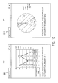
- This window GM4 shows a pie graph of the percentage of total sales occupied by each category of products in the one store specified by the management device 14 in the one month specified by the management device 14.
- the user displays a specific user interface on the management device 14, and inputs store identification information for one store and information identifying the one month (for example, January 2013) to the user interface. Fields for inputting the information are provided in the specific user interface. The above information is sent to the control server 10 in response to the input.
- the information provider unit 49a of the control server 10 references the store management database, and based on the store identification information, acquires the firstprinter identification information for a receipt printer 12a installed in the specified store.
- the information provider unit 49a finds the records in the analytical information database related to the specified store and the specified period based on the printer identification information field F12 and the date stamp information field F3.
- the information provider unit 49a accesses the product category database and based on the purchase information fields F7 in the selected records, calculates the percentage of total sales occupied by each category of products in the one store specified by the management device 14 in the one month specified by the management device 14.
- the information provider unit 49a generates a drawing file for displaying the information in the format shown in panel (B) of FIG. 10 , sends the drawing file to the management device 14, and displays the window GM4.
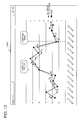
- Panel (A) of FIG. 11 (A) shows an example of a window GM5 that the control server 10 displays on the management device 14 in response to a request from the management device 14.
- This window GM5 shows a broken line graph of sales by product category during a period specified by the management device 14 for one store specified by the management device 14.
- the user displays a specific user interface on the management device 14, and inputs store identification information for the one store and information identifying the period (for example, January 2013 to April 2013) to the user interface. Fields for inputting the information are provided in the specific user interface. The above information is sent to the control server 10 in response to the input.
- the information provider unit 49a of the control server 10 references the store management database, and based on the store identification information, acquires the firstprinter identification information for a receipt printer 12a installed in the specified store.
- the information provider unit 49a finds the records in the analytical information database related to the specified store and the specified period based on the printer identification information field F12 and the date stamp information field F3.
- the information provider unit 49a finds the records in the analytical information database related to the specified store and the specified period based on the printer identification information field F12 and the date stamp information field F3.
- the information provider unit 49a accesses the product category database and based on the purchase information fields F7 in the selected records, calculates the change in sales for each product category in the period specified by the management device 14.
- the information provider unit 49a generates a drawing file for displaying information in the format shown in panel (A) of FIG. 11 , sends the drawing file to the management device 14, and displays the window GM5.
- Panel (B) of FIG. 11 shows another example of a window GM6 that the control server 10 displays on the management device 14 in response to a request from the management device 14.
- This window GM6 shows a bar graph of the percentage of total sales occupied by each category of products in the one store specified by the management device 14 in the period specified by the management device 14.
- the user displays a specific user interface on the management device 14, and inputs store identification information for one store and information identifying the period (for example, January 2013 to April 2013) to the user interface. Fields for inputting the information are provided in the specific user interface. The above information is sent to the control server 10 in response to the input.
- the information provider unit 49a of the control server 10 references the store management database, and based on the store identification information, acquires the firstprinter identification information for a receipt printer 12a installed in the specified store.
- the information provider unit 49a finds the records in the analytical information database related to the specified store and the specified period based on the printer identification information field F12 and the date stamp information field F3.
- the information provider unit 49a accesses the product category database and based on the purchase information fields F7 in the selected records, calculates the percentage of total sales occupied by each category of products in each month in the period specified by the management device 14.
- the information provider unit 49a generates a drawing file for displaying the information in the format shown in panel (B) of FIG. 11 , sends the drawing file to the management device 14, and displays the window GM6.
- FIG. 12 shows another example of a window GM7 that the control server 10 displays on the management device 14 in response to a request from the management device 14.
- This window GM7 shows a pie graph of the relationship between the profit margin of products and sales of those products in the one store specified by the management device 14 in the one month specified by the management device 14.
- the user displays a specific user interface on the management device 14, and inputs store identification information for one store and information identifying the one month (for example, January 2013) to the user interface. Fields for inputting the information are provided in the specific user interface. The above information is sent to the control server 10 in response to the input.
- the information provider unit 49a of the control server 10 references the store management database, and based on the store identification information, acquires the first printer identification information for a receipt printer 12a installed in the specified store.
- the information provider unit 49a finds the records in the analytical information database related to the specified store and the specified period based on the printer identification information field F12 and the date stamp information field F3.
- the information provider unit 49a accesses the product category database and based on the purchase information fields F7 in the selected records, calculates the profit margin of the products and the sales of each product. Next, based on the calculated result, the information provider unit 49a generates a drawing file for displaying the information in the format shown in FIG. 12 sends the drawing file to the management device 14, and displays the window GM7.
- FIG. 13 shows another example of a window GM8 that the control server 10 displays on the management device 14 in response to a request from the management device 14.
- This window GM8 shows a broken line graph of store sales and the number of transactions each day during a period specified by the management device 14 for a store specified by the management device 14. If a campaign period is specified by the management device 14, the campaign period is clearly identified in the window GM8.
- the number of transactions is the number of transactions (payments) made by customers that came to the store. Because first receipts are produced according to the customer transactions, the number of transactions can be acquired based on the number of first receipts printed.
- the user displays a specific user interface on the management device 14, and inputs store identification information for one store and information identifying the period (for example, March 10, 2013 to March 23, 2013) to the user interface. As may be necessary, the user also inputs the campaign period. Fields for inputting the information are provided in the specific user interface. The above information is sent to the control server 10 in response to the input.
- the information provider unit 49a of the control server 10 references the store management database, and based on the store identification information, acquires the firstprinter identification information for a receipt printer 12a installed in the specified store.
- the information provider unit 49a finds the records in the analytical information database related to the specified store and the specified period based on the printer identification information field F12 and the date stamp information field F3.
- the information provider unit 49a acquires the number of transactions per day based on the number of records recorded each day during the specified period. Next, the information provider unit 49a calculates the sales on each day included in the specified period based on the total purchase amount information field F5 in the selected records. Next, based on the acquired number of transactions and the calculated result, or based on the campaign period when a campaign period is specified, the information provider unit 49a generates a drawing file for displaying information in the format shown in FIG. 13 , sends the drawing file to the management device 14, and displays the window GM8.
- the POS control system 1 includes a POS terminal 8, a receipt printer 12a (printing device), and control server 10 (data processing device).
- the POS terminal 8 sends print data including transaction information.
- the receipt printer 12a has a first USB communication unit 34a that receives print data sent by the POS terminal 8; a first printer storage unit 39a (identification information storage unit) that stores first printer identification information (identification information) ; a first print unit 41a (print unit) that prints; a first print control unit 29a that controls the first print unit 41a (print unit) based on print data; and a first communication unit 30a (transmission unit) that sends print data and first printer identification information data including the first printer identification information.
- the control server 10 has a control server storage unit 57 (device storage unit) that stores relation information relating printer identification information to the layout for printing information based on the print data; a first connection unit 54 (connection unit) that receives the print data and first printer identification information sent by the receipt printer 12a; and a data analysis unit 51a that acquires the layout related to the printer identification information based on the relation information stored by the control server storage unit 57, and analyzes the print data by the method corresponding to the layout.
- a control server storage unit 57 device storage unit
- first connection unit 54 connection unit
- a data analysis unit 51a that acquires the layout related to the printer identification information based on the relation information stored by the control server storage unit 57, and analyzes the print data by the method corresponding to the layout.
- control server 10 can analyze print data by a method that corresponds to the print data and reflects the layout of the information print data based on the print data.
- the data analysis unit 51a of the control server 10 stores information based on analyzing the print data in the control server storage unit 57 (analytical result storage unit).
- the stored information can be used to execute processes such as analyzing sales based on transaction information.
- control server 10 has a data communication unit 58 that sends information based on analysis of the print data by the data analysis unit 51a.
- information based on analyzing print data can be sent to an external device such as the management device 14, displayed by the external device based on the information, and the result of analysis by the data analysis unit 51a can be provided to the user referring to the display.
- control server 10 has a data processing unit 51b that processes print data based on analysis of the print data by the data analysis unit 51a.
- the print data can be processed to generate print data producing a printout with a different layout, or to generate print data producing a printout with specific styling applied.
- the second connection unit 55 (connection unit) of the control server 10 sends the print data (second receipt print data) processed by the data processing unit 51b to a second printer 12b (external device) .
- control server 10 can control the second printer 12b to print based on print data (second receipt print data) processed by the data processing unit 51b.
- control server 10 provides information to the management device 14 in the embodiment described above, but the information the control server 10 provides to the management device 14 or other external device is not limited to the information described above.
- the receipt printer 12a and other devices are also disposed to a store system 11 used in a retail business in the foregoing embodiment.
- the devices are not necessarily limited to devices used in a store system 11.
- the devices may, for example, be used in a different type of system.
- the function blocks shown in FIG. 3 can be embodied by hardware and software, and do not suggest a specific hardware configuration.
Abstract
Description
- Priority is claimed under 35 U.S.C. § 119 to Japanese Application no.
2014-032868 filed on February 24, 2014 - The present disclosure relates to a POS system that includes a printing device, and to a data processing device used in the POS system.
- Devices with functions for creating print data and analyzing print data that was created are known from the literature. See, for example,
JP-A-2012-058810 - When a data processing device is connected to a printer in a POS system such as described above, and the data processing device analyzes the print data, it is necessary to analyze the print data based on the layout of the specific receipt because the layout of the printed receipt may vary according to the print data.
- In a POS system having a data processing device and a printer that prints based on print data received from a POS terminal, an object of the present invention is to enable the data processing device to analyze the print data appropriately to the layout of the receipt.
- In view of this obj ect, the present invention proposes a POS system including a printing device, a data processing device and a control method of a printing system having the features of the respective independent claims.
- One aspect of the invention relates to a POS system including a POS terminal that sends print data including transaction information; a printing device including a reception unit that receives the print data sent by the POS terminal, an identification information storage unit that stores identification information, a print unit that prints a receipt based on the print data, a print control unit that controls the print unit based on the print data, and a transmission unit that transmits the print data and the identification information; and a data processing device including a relation information storage unit that stores relation information linking layout information for the receipt printed by the print unit to the identification information, a connection unit that receives the print data and the identification information transmitted by the printing device, and an analysis unit that acquires the layout information related to the identification information received by the connection unit based on the relation information stored in the relation information storage unit, and based on the acquired layout information analyzes the print data (i.e. analyzes the print data in dependence on the acquired layout information, e.g. analyzes the print data using the acquired layout information).
- The data processing device stores identification information relationally to layout information, and when identification information and print data are received from the printing device, retrieves the related layout information based on the identification information (i.e. retrieves the layout information relationally stored to the received identification information) and analyzes the print data based on the layout information (e.g. analyzes the print data using, or referencing the layout information). The data processing device can therefore analyze print data by referencing the layout of the receipt that is printed based on the print data.
- Preferably, the data processing device also has an analytical result storage unit that stores analytical results based on the analysis of the print data (e.g. that stores analytical results of the analysis of the print data by the analysis unit, or analytical results obtained by said analysis).
- Thus comprised, the data processing device can execute processes such as analyzing sales data using the stored analytical results.
- Further preferably, the data processing device has a data communication unit that transmits the analytical results from the analysis unit.
- Thus comprised, the data processing device sends analytical results based on the analysis of the print data to an external device. As a result, processes such as the external device presenting a display based on the information and providing the results of the analysis by the analysis unit to the user viewing the display are possible.
- Yet further preferably, the data processing device has a processing unit that processes the print data based on the analytical results from the analysis unit.
- Thus comprised, the data processing device can process print data and generate print data for producing printouts with different layouts, or print data for producing printouts with specific styling applied.
- A POS system according to another aspect of the invention also has an external device that prints; and the connection unit of the data processing device connects to the external device and transmits data processed by the processing unit to the external device.
- Thus comprised, the data processing device can control the external device to print based on print data processed by the data processing unit.
- A POS system according to another aspect of the invention also has a second POS terminal that sends second print data including transaction information; a second printing device including a second reception unit that receives the second print data sent by the second POS terminal, a second identification information storage unit that stores second identification information, a second print unit that prints a second receipt based on the second print data, a second print control unit that controls the second print unit based on the second print data, and a second transmission unit that transmits the second print data and the second identification information. The relation information storage unit of the data processing device stores second relation information linking second layout information for the second receipt printed by the second print unit to the second identification information; the connection unit of the data processing device receives the second print data and the second identification information transmitted by the second printing device; and the analysis unit of the data processing device acquires the second layout information related to the second identification information received by the connection unit based on the second relation information stored in the relation information storage unit (e.g. the analysis unit acquires the second layout information that is linked to the received second identification information by the second relation information), and based on the acquired second layout information analyzes the second print data.
- Thus comprised the data processing device can analyze print data received from plural different printing devices based on the specific layout used by each printing device.
- Another aspect of the invention relates to a data processing device including: a connection unit that receives print data instructing printing a receipt, and identification information of the device that has transmitted the print data; a relation information storage unit storing relation information, wherein the relation information relationally stores layout information of the receipt printed based on the print data and the identification information (e. g. the relation information links layout information to related, or corresponding, identification information); and an analysis unit that acquires the layout information related to the identification information received by the connection unit based on the relation information stored in the relation information storage unit, and based on the acquired layout information analyzes the print data.
- Thus comprised, data processing device can analyze print data by referencing the layout of the receipt that is printed based on the print data.
- Preferably, the data processing device also has an analytical result storage unit that stores analytical results based on the analysis of the print data (e.g. that stores analytical results of the analysis of the print data by the analysis unit); and a processing unit that processes the print data based on the analytical results from the analysis unit.
- Thus comprised, the data processing device can execute processes such as analyzing sales data using the stored analytical results, and can process the print data and generate print data for producing printouts with different layouts, or print data for producing printouts with specific styling applied.
- Other objects and attainments together with a fuller understanding of the invention will become apparent and appreciated by referring to the following description and claims taken in conjunction with the accompanying drawings.
-
-
FIG. 1 exemplarily shows the configuration of a POS system according to an embodiment of the invention. -
FIG. 2 exemplarily illustrates communication paths opened between a control server in the POS system and devices connected to the control server. -
FIG. 3 is an exemplary block diagram showing the functional configuration of devices in the POS system. -
FIG. 4 is an exemplary flow chart showing the operation of a first printing device in the POS system and the control server. -
FIG. 5 is an exemplary flow chart showing the operation of devices in the POS system. -
FIG. 6 shows examples of receipts and the layout thereof. -
FIG. 7 is an exemplary flow chart of steps in the analytical process of the control server. -
FIG. 8 shows an example of the data structure of one record in an analytical information database of the control server. -
FIG. 9 shows an example of a window displayed by the control server based on the result of print data analysis. -
FIG. 10 shows another example of a window displayed by the control server based on the result of print data analysis. -
FIG. 11 shows another example of a window displayed by the control server based on the result of print data analysis. -
FIG. 12 shows another example of a window displayed by the control server based on the result of print data analysis. -
FIG. 13 shows another example of a window displayed by the control server based on the result of print data analysis. - A preferred embodiment of the present invention is described below with reference to the accompanying figures.
-
FIG. 1 shows the configuration of an example of aPOS system 1 according to a preferred embodiment of the invention. - As shown in
FIG. 1 , the POS (point-of-sale)system 1 includes a control server 10 (data processing device). A plurality ofstore systems 11 may connect to thecontrol server 10 through the Internet or other network GN.Plural management devices 14 may also be connected to the network GN. - The
store system 11 is a system that may be used in retail businesses such as supermarkets, convenience stores, department stores, and restaurants. Thestore system 11 has functions including producing receipts for customers that completed a transaction at the store. - The
store system 11 has one ormore receipt printers 12a (printing devices) each having a printing function for printing on print media and capable of producing receipts. Thestore system 11 also may have one or apluralityofsecond printers 12b that also have a print function. - The
receipt printers 12a andsecond printers 12b may be connected to a local area network LN deployed in the store. Anetwork communication controller 13 configured with a communication device such as a network router or modem, for example, may connect to the local area network LN. Thereceipt printers 12a andsecond printers 12b may access the network GN through thenetwork communication controller 13. Thereceipt printers 12a andsecond printers 12b may be connected to thecontrol server 10 via the network GN. - The
receipt printer 12a connects to aPOS terminal 8 in thestore system 11. A POS application and printer driver are installed on thePOS terminal 8. - The
POS terminal 8 controls thereceipt printer 12a to produce a first receipt by generating and sending print data to thereceipt printer 12a. ThePOS terminal 8 has a POSapplication execution unit 45a that executes functions according to the POS application, and a printerdriver execution unit 45b that executes functions according to the printer driver. ThePOS terminal 8 controls thereceipt printer 12a by means of the POSapplication execution unit 45a and printerdriver execution unit 45b. While described in further detail below, thePOS terminal 8 controls thereceipt printer 12a to produce the first receipt by generating and sending the print data by means of the POSapplication execution unit 45a and printerdriver execution unit 45b to thereceipt printer 12a. - While not shown in the figures, a barcode reader that reads barcodes from products or product packaging, and a card reader that reads cards such as customer membership cards, may also connect to the
POS terminal 8. By a function of the POS application, thePOS terminal 8 may access a POS server not shown inFIG. 1 to acquire specific information from product master and customer master databases stored by the POS server. Based on input from the barcode reader, card reader, and input by the checkout clerk to input means such as a keypad according to the customer transaction in the store, thePOS terminal 8 may acquire information from the product master and customer master databases and generate print data. - While described in detail below, the
second printer 12b also produces a second receipt (described below) corresponding to the first receipt by a function of thecontrol server 10 based on the customer transaction at the store. - One or a plurality of checkout counters RC are set up in the store. A
receipt printer 12a, aPOS terminal 8 that connects to thereceipt printer 12a, and asecond printer 12b corresponding to thereceipt printer 12a are installed at each checkout counter RC. - In the example shown in
FIG. 1 , thestore system 11A is a system used in a supermarket SM. Plural checkout counters RC are set up in the supermarket SM. Areceipt printer 12a, aPOS terminal 8, and asecond printer 12b are installed at each checkout counter RC. ThePOS terminal 8 sends print data to thereceipt printer 12a according to the transaction at the checkout counter RC. Thereceipt printer 12a then produces a first receipt based on the print data. Thesecond printer 12b at the checkout counter RC also produces a second receipt by a function of thecontrol server 10. - The
receipt printers 12a andsecond printers 12b of thestore system 11A access the network GN through thenetwork communication controller 13 of the local area network LN, and communicate through the network GN with thecontrol server 10. - In the
POS system 1 according to this embodiment of the invention eachreceipt printer 12a andsecond printer 12b of thestore system 11 establishes a communication connection with thecontrol server 10, and communicates with thecontrol server 10 through the established communication path. As described further below, thecontrol server 10 gets the print data thePOS terminal 8 sent to thereceipt printer 12a through the communication path established with thereceipt printer 12a, and executes a processes including a process of analyzing the acquired print data. - The
control server 10 processes the print data based on the result of analyzing the print data to generate processed print data, and sends the processed print data to thesecond printer 12b. Thesecond printer 12b then prints a second receipt based on the processed print data. - The
management device 14 is a device that manages one ormore store systems 11. For example, themanagement device 14 may be installed in the headquarters of a company that operates multiple stores, and manage thestore systems 11 deployed in plural stores of the corporate group. -
FIG. 2 exemplarily illustrates the communication paths established between thecontrol server 10 and thereceipt printers 12a andsecond printers 12b in thePOS system 1. - As shown in
FIG. 2 , a WebSocket connection CT enabling WebSocket communication may be established in thePOS system 1 between thecontrol server 10 and thereceipt printers 12a in eachstore system 11. A WebSocket connection CT enabling WebSocket communication may also be established in thePOS system 1 between thecontrol server 10 and thesecond printers 12b in thestore system 11. - WebSocket is a communication standard that enables asynchronous duplex communication. After a server and client open a WebSocket connection CT using the WebSocket standard, sending and receiving data between the devices uses the WebSocket protocol by means of the connection. It is therefore not necessary to establish a connection every time data is transmitted.
- The WebSocket connection CT is a logical communication path for sending and receiving data according to the WebSocket standard and procedures between the
receipt printers 12a orsecond printers 12b andcontrol server 10 connected through the WebSocket connection CT. Therefore, once areceipt printer 12a orsecond printer 12b andcontrol server 10 handshake and establish a WebSocket connection CT, thereceipt printer 12a orsecond printer 12b andcontrol server 10 can exchange data asynchronously over the WebSocket connection CT. More specif ically, thecontrol server 10 can push data to thereceipt printer 12a orsecond printer 12b through the WebSocket connection CT at any time, and thereceipt printer 12a orsecond printer 12b can push data to thecontrol server 10 at the desired time through the WebSocket connection CT. - WebSocket communication is asynchronous, duplex communication between a
receipt printer 12a orsecond printer 12b and thecontrol server 10 through the WebSocket connection CT based on the WebSocket protocol and methods. - As also shown in
FIG. 2 , thecontrol server 10 may also be communicatively connected to theplural management devices 14. - In this example of an embodiment of the invention, the
control server 10 is a client server in a so-called cloud system in which thereceipt printers 12a,second printers 12b andmanagement devices 14 are client devices. Thecontrol server 10 can process data, execute specific processes when triggered by receiving a request from areceipt printer 12a, printer 12,management device 14, or other external device or when specific conditions are met, and send data based on the result of the process through the WebSocket connection CT to thereceipt printer 12a,second printer 12b, ormanagement device 14. - In
FIG. 2 thecontrol server 10 is represented as a single block, but this does not mean that thecontrol server 10 is configured from a single server. For example, thecontrol server 10 maybe configured from multiple servers, or it may be a server rendered by a function of a specific system. More specifically, thecontrol server 10 may be any configuration that can execute the processes described herein. - The
control server 10 andreceipt printer 12a, and thecontrol server 10 and thesecond printer 12b, communicate according to the WebSocket communication protocol in this example of the embodiment. The invention is not limited to WebSocket communication, however, and other configurations enabling devices to communicate by asynchronous, duplex communication similarly to WebSocket communication may be used. - The
POS system 1 thus may have multiple (such as a 1000)receipt printers 12a each capable of printing andsecond printers 12b each capable of printing communicatively connected through a WebSocket connection CT to acontrol server 10. - The
control server 10 can collect data received from theplural receipt printers 12a andsecond printers 12b connected toplural store systems 11, and manage and analyze information based on the collected data. The accumulated information can be used as so-called "big data". - As described further below, the
POS terminal 8 can control thesecond printer 12b to execute a process corresponding to the print data sent to thereceipt printer 12a by a function of thecontrol server 10. A process appropriate to the print data can be executed on thesecond printer 12b by a function of thecontrol server 10 in this embodiment of the invention by the simple task of connecting thereceipt printer 12a andsecond printer 12b to the network GN. As also described further below, thesecond printer 12b can also execute processes using a function of thecontrol server 10 without modifying the existing system in which areceipt printer 12a is connected to aPOS terminal 8, and without affecting the existing system. -
FIG. 3 is a block diagram exemplarily showing the functional configuration of thereceipt printer 12a,second printer 12b, thePOS terminal 8, thecontrol server 10, and themanagement device 14 in this embodiment of the invention. - As shown in
FIG. 3 , thereceipt printer 12a has afirst interface board 20a and afirst printer board 21a. These boards are connected by aconnector 22a disposed to thefirst interface board 20a, and aconnector 23a disposed to thefirst printer board 21a. InFIG. 3 , the function blocks are shown inside the blocks representing the boards (first interface board 20a andfirst printer board 21a) inside the block representing thereceipt printer 12a. This means the function of one function block is embodied by specific software and hardware (such as a CPU or signal processing circuit) mounted on the circuit board corresponding to the one function block. - The
first interface board 20a of thereceipt printer 12a includes afirst control unit 24a, afirst communication unit 30a (exemplarily embodying a transmission unit), a firstUSB communication unit 34a (exemplarily embodying a reception unit), and a firstprinter storage unit 39a (exemplarily embodying an identification information storage unit). - The
first control unit 24a includes a firstcommunication control unit 25a, a first printdata communication unit 26a, and a firstprint control unit 29a (exemplarily embodying a print control unit) . These function blocks are described further below. The functions of the firstcommunication control unit 25a, first printdata communication unit 26a, firstprint control unit 29a, andfirst communication unit 30a are also described further below. - The first
USB communication unit 34a is connected to a USB port not shown, and communicates by the USB protocol with thePOS terminal 8 connected through a USB cable. - In this embodiment of the invention, the
receipt printer 12a communicates by USB with thePOS terminal 8, but configurations using other communication protocols maybe used. For example, a configuration that communicates by a serial communication protocol such as RS232-C may be used. - The first
printer storage unit 39a stores data. The data the firstprinter storage unit 39a stores is described further below. - The
first printer board 21a of thereceipt printer 12a has a firstprinter control unit 40a. The function of the firstprinter control unit 40a is described further below. - The
receipt printer 12a also has afirst print unit 41a (exemplarily embodying a print unit). Roll paper is loaded in thereceipt printer 12a. Thefirst print unit 41a has various mechanisms and devices, including a print mechanism for printing on the roll paper set in thereceipt printer 12a, a conveyance mechanism for conveying the roll paper, and a cutter mechanism for cutting the roll paper. Thefirst print unit 41a may produce receipts. - As shown in
FIG. 3 , thesecond printer 12b has asecond interface board 20b and asecond printer board 21b. These boards are connected by aconnector 22b disposed to thesecond interface board 20b, and aconnector 23b disposed to thesecond printer board 21b. - The
second interface board 20b of thesecond printer 12b includes asecond control unit 24b, asecond communication unit 30b (exemplarily embodying a second reception unit and a second transmission unit), and a secondprinter storage unit 39b (exemplarily embodying a second identification information storage unit) . Thesecond control unit 24b includes a second printdata communication unit 26b, and a secondprint control unit 2 9b as function blocks. These function blocks are described further below. The functions of the second printdata communication unit 26b, secondprint control unit 29b, andsecond communication unit 30b are also described further below. - The second
printer storage unit 39b stores data. The data the secondprinter storage unit 39b stores is described further below. - The
second printer board 21b of thesecond printer 12b has a secondprinter control unit 40b. The function of the secondprinter control unit 40b is described further below. - The
second printer 12b also has a second print unit 41b. Roll paper is loaded in thesecond printer 12b. The second print unit 41b has various mechanisms and devices, including a print mechanism for printing on the roll paper set in thesecond printer 12b, a conveyance mechanism for conveying the roll paper, and a cutter mechanism for cutting the roll paper. - As shown in
FIG. 3 , thePOS terminal 8 includes a POSterminal control unit 45 and aterminal communication interface 46. - The POS
terminal control unit 45 includes a CPU, ROM, RAM, and other peripheral circuits, and controls thePOS terminal 8. The function blocks of the POSterminal control unit 45 include the POSapplication execution unit 45a and the printerdriver execution unit 45b. - The function of the POS
application execution unit 45a is controlled by the POS application installed on thePOS terminal 8. Based on input from the barcode reader, card reader, and input by the checkout clerk to input means such as a keypad according to the transaction performed at the checkout counter RC, the POSapplication execution unit 45a acquires information from the product master and customer master databases, generates print information data including information related to printing, and outputs to the printerdriver execution unit 45b. - The printer
driver execution unit 45b is embodied by functions of the printer driver installed on thePOS terminal 8. Based on the print information data received from the POSapplication execution unit 45a, the printerdriver execution unit 45b generates and outputs print data according to the command language of thefirst print unit 41a of thereceipt printer 12a. - The
terminal communication interface 46 communicates according to a specific communication protocol with thereceipt printer 12a as controlled by the POSterminal control unit 45. - As shown in
FIG. 3 , thecontrol server 10 includes aserver control unit 49, a first connection unit 54 (exemplarily embodying a connection unit 52), a second connection unit 55 (exemplarily embodying the connection unit 52), a control server storage unit 57 (exemplarily embodying a relation information storage unit, and analytical result storage unit), and adata communication unit 58. - A function block of the
server control unit 49 is the printdata process unit 51. The printdata process unit 51 is described further below. - The functions of the
first connection unit 54 andsecond connection unit 55 are also described further below. - The control
server storage unit 57 stores data. The data the controlserver storage unit 57 stores is described further below. - The
communication unit 58 communicates according to a specific communication protocol with an external device, including themanagement device 14, through the network GN as controlled by theserver control unit 49. - As shown in
FIG. 3 , themanagement device 14 has a managementdevice control unit 70, a managementdevice communication interface 71, and a managementdevice storage unit 72. - The management
device control unit 70 includes a CPU, ROM, RAM, and other peripheral circuits, and controls themanagement device 14. - The management
device communication interface 71 communicates according to a specific communication protocol with thecontrol server 10 through the network GN as controlled by the managementdevice control unit 70. - The management
device storage unit 72 stores data. The data the managementdevice storage unit 72 stores is described further below. -
FIG. 3 shows the relationship between thecontrol server 10 and onereceipt printer 12a connected to thecontrol server 10.Whenmultiple receipt printers 12a are connected to thecontrol server 10, thecontrol server 10 may establish a WebSocket connection CT with eachreceipt printer 12a, and communicate with thereceipt printers 12a by the WebSocket standard through the WebSocket connection CT. The same applies to thesecond printers 12b. -
FIG. 3 also shows the relationship between thecontrol server 10 and onemanagement device 14 connected to thecontrol server 10. Whenmultiple management devices 14 are connected to thecontrol server 10, thecontrol server 10 may establish a WebSocket connection CT with eachmanagement device 14, and communicate with themanagement devices 14 through the WebSocket connection CT. - Operation of the
receipt printer 12a and thecontrol server 10 when thereceipt printer 12a power turns on is described next. - When not specifically differentia ting between the
receipt printer 12a and thesecond printer 12b below, they are referred to as simply printer 12. -
FIG. 4 is a flow chart exemplarily showing the operation of thereceipt printer 12a and thecontrol server 10 after thereceipt printer 12a power turns on, column (A) showing the operation of thereceipt printer 12a, and column (B) showing the operation of thecontrol server 10. - Note that the trigger for the process shown in the flow chart in
FIG. 4 is not limited to the power turning on. For example, the process may also be triggered by thereceipt printer 12a connecting communicatively to the network GN, or when a command is received from the user. - As shown in column (A) of
FIG. 4 , when thereceipt printer 12a power turns on (step SX1), the first printdata communication unit 26a accesses the firstprinter storage unit 39a and gets the first address data stored in the firstprinter storage unit 39a (step SA1). - The first address data is data including the address (such as the domain name, IP address, path name, or port name, for example) of the
control server 10 to access when establishing a first WebSocket connection CT1 according to the WebSocket protocol. When opening a WebSocket connection CT according to the WebSocket protocol, the client (thereceipt printer 12a in this example) handshakes with the server (thecontrol server 10 in this example) using HTTP (Hypertext Transfer Protocol). When handshaking, the client sends a message containing the domain name of the server, and the first address data is data required to establish a WebSocket connection CT, including the address to access. - Next, the first print
data communication unit 26a accesses thecontrol server 10 based on the address identified by the first address data. Next, the first printdata communication unit 26a exchanges the information required to establish a connection with the printdata process unit 51 of thecontrol server 10, and establishes a first WebSocket connection CT1 between thefirst communication unit 30a and the first connection unit 54 (step SA2, step SB1). The first printdata communication unit 26a of thereceipt printer 12a establishes the first WebSocket connection CT1 when triggered by any of the above-mentioned triggers, e. g. by thereceipt printer 12a power turning on, even without receiving a request from thecontrol server 10. - The
first communication unit 30a and thefirst connection unit 54 are WebSocket interfaces enabling data communication based on the WebSocket protocol and methods. These function blocks are instantiated using a WebSocket Socket.IO library, for example. This also applies to thesecond communication unit 30b of thesecond printer 12b andsecond connection unit 55 of thecontrol server 10. - The
first communication unit 30a has functions for processing data that is received from the first printdata communication unit 26a according to WebSocket, and sending the data through the first WebSocket connection CT1 based on WebSocket methods. - The
first communication unit 30a also has functions for processing data that is received through the first WebSocket connection CT1 according to WebSocket, and sending to the first printdata communication unit 26a. Thefirst connection unit 54,second communication unit 30b, andsecond connection unit 55 are similarly configured. - By establishing a first WebSocket connection CT1, the
receipt printer 12a and thecontrol server 10 can communicate by asynchronous, duplex communication. Thecontrol server 10 can push data to thereceipt printer 12a through the first WebSocket connection CT1 without receiving a request from thereceipt printer 12a operating as a client device. Likewise, thereceipt printer 12a can push data to thecontrol server 10 through the first WebSocket connection CT1. - By establishing a first WebSocket connection CT1, the first print
data communication unit 26a of thereceipt printer 12a and the printdata process unit 51 of thecontrol server 10 open a first function unit communication path KT1 based on the first WebSocket connection CT1. The first function unit communication path KT1 is a logical communication path for data communication between the first printdata communication unit 26a and the printdata process unit 51. The first printdata communication unit 26a and printdata process unit 51 can communicate by asynchronous duplex communication through the first function unit communication path KT1. Asynchronous duplex communication through the first function unit communication path KT1 is described further below. - Next, the first print
data communication unit 26a accesses the firstprinter storage unit 39a, and gets the first printer identification information data stored in the firstprinter storage unit 39a (step SA3). The first printer identification information data is data identifying aparticular receipt printer 12a. Below, the identification information of a printer 12 is referred to as printer identification information. The printer identification information may be, for example, the serial number assigned to the printer 12 when the printer 12 was manufactured. - Next, the first print
data communication unit 26a sends the first printer identification information data to the first communication unit 30 (step SA4). - The
first communication unit 30 sends the received first printer identification information data through the first WebSocket connection CT1 to the control server 10 (step SA5). - As shown in FIG. in column (B) of
FIG. 4 , thefirst connection unit 54 of thecontrol server 10 receives the first printer identification information data through the first WebSocket connection CT1 (step SB2) . Next, thefirst connection unit 54 sends the received first printer identification information data to the print data process unit 51 (step SB3). - The print
data process unit 51 then accesses the connection management database stored by the control server storage unit 57 (step SB4). The connection management database is a database relationally storing connection identification information identifying the WebSocket connection CT and the printer identification information of the printer 12 for each of the WebSocket connections CT that were established between thecontrol server 10 and printers 12. - Next, the print
data process unit 51 creates one record in the connection management database. The printdata process unit 51 then relationally stores in the created record the connection identification information of the WebSocket connection CT established in step SB1 (the first WebSocket connection CT1 in this example) and the printer identification information indicated by the first printer identification data that was received (step SB5). - Note that when a WebSocket connection CT is opened, the print
data process unit 51 generates connection identification information for that connection that is different from the connection identification information of any other WebSocket connection CT that was already opened, i.e. unique connection identification information. The relationship between the WebSocket connections CT and printers 12 is managed by the process of step SB5. - The print
data communication unit 26a of thereceipt printer 12a thus establishes a first WebSocket connection CT1 when triggered by any one of the above-mentioned triggers, e.g. the power of thereceipt printer 12a turning on, without receiving a request from thecontrol server 10. Thus comprised, the user does not need to perform a complicated operation to open a first WebSocket connection CT1. The user also does not need special knowledge to open a first WebSocket connection CT1. - Operation of the
receipt printer 12a andcontrol server 10 when establishing a first WebSocket connection CT1 is described above, and thesecond printer 12b similarly establishes a second WebSocket connection CT2 with thecontrol server 10 when triggered by any of the above-mentioned triggers, e.g. when the printer power turns on. - Operation when the second WebSocket connection CT2 is established is described next.
- When the power of the
second printer 12b turns on, the second printdata communication unit 26b exchanges the information required to establish a connection with the printdata process unit 51 of thecontrol server 10, and establishes a second WebSocket connection CT2 between thesecond communication unit 30b and thesecond connection unit 55. When the connection is established, the printdata process unit 51 of thecontrol server 10 relationally stores the connection identification information of the established WebSocket connection CT and the printer identification information indicative of thesecond printer 12b (referred to below as second printer identification information). A second function unit communication path KT2 based on the connection is also established between the printdata process unit 51 of thecontrol server 10 and the second printdata communication unit 26b of thesecond printer 12b when the second WebSocket connection CT2 is established. Data communication through the second WebSocket connection CT2 is described below. - The
POS control system 1 is configured from a system including areceipt printer 12a and aPOS terminal 8. In this system, thePOS terminal 8 generates and sends print data using the POSapplication execution unit 45a and printerdriver execution unit 45b to thereceipt printer 12a. Based on the print data, thereceipt printer 12a prints with thefirst print unit 41a and products a first receipt. - Without modifying the program of the POS application, the
POS control system 1 can also execute specific processes using functions of thecontrol server 10 using print data that thePOS terminal 8 sends to thereceipt printer 12a. - More specifically, a
first interface board 20a is disposed to thereceipt printer 12a, and the additional functions embodied by thefirst interface board 20a are thereby added to thereceipt printer 12a. Using these added functions, thereceipt printer 12a sends print data through the network GN to thecontrol server 10. Thecontrol server 10 executes processes including analyzing the print data based on the received print data. - Operation of devices in the
POS control system 1 when thePOS terminal 8 sends print data to thereceipt printer 12a is described next. -
FIG. 5 is a flow chart exemplarily showing the operation of devices in thePOS control system 1 when thePOS terminal 8 sends print data to thereceipt printer 12a. Column (A) ofFIG. 5 shows the operation of thePOS terminal 8, column (B) shows the operation of thereceipt printer 12a, column (C) shows the operation of thecontrol server 10, and column (D) shows the operation of thesecond printer 12b. - Asynchronous duplex communication between the first print
data communication unit 26a and the printdata process unit 51 through the first function unit communication path KT1, and asynchronous duplex communication between the second printdata communication unit 26b and the printdata process unit 51 through the second function unit communication path KT2, are also described below. - As shown in column (A) of
FIG. 5 , the POSapplication execution unit 45a and printerdriver execution unit 45b of the POSterminal control unit 45 of thePOS terminal 8 generate print data including transaction information when processing a transaction at the checkout counter RC (step SC1). The print data is data instructing producing a receipt based on the transaction process at the checkout counter RC. - The print data generated in step SC1 is binary data.
- Next, the POS
terminal control unit 45 controls theterminal communication interface 46 and sends the print data to thereceipt printer 12a (step SC2). - As shown in column (B) of
FIG. 5 , the firstUSB communication unit 34a receives the print data sent from the POS terminal 8 (step SD1). Next, the firstUSB communication unit 34a sends the received print data to the firstcommunication control unit 25a (step SD2). - Next, the first
communication control unit 25a sends the received print data to the firstprint control unit 29a and the first printdata communication unit 26a (step SD3). - Based on the print data received from the first
communication control unit 25a, the firstprint control unit 29a controls the firstprinter control unit 40a to execute the receipt printing process by thefirst print unit 41a (step SD4) . In this embodiment of the invention the firstprint control unit 29a and firstprinter control unit 40a communicate by USB, but the communication protocol used by the firstprint control unit 29a and firstprinter control unit 40a is not limited to USB. For example, communication based on the Serial Peripheral Interface (SPI) specification or other communication specification may also be used. - Note also that the first
printer control unit 40a is a control circuit that operates thefirst print unit 41a. - The
first print unit 41a produces a first receipt as controlled by the firstprinter control unit 40a (step SD5). - The first receipt is described below.
- Panel (A1) of
FIG. 6 shows a first receipt RA as an example of a first receipt. This first receipt RA is a first receipt produced by thereceipt printer 12a in thestore system 11 of a store A with the store name A_Coffee. - Panel (B1) of
FIG. 6 shows a first receipt RB as another example of a first receipt. This first receipt RB is a first receipt produced by thereceipt printer 12a in thestore system 11 of another store B with the store name B_Coffee, which is a different store than store A. - As will be clear by comparing panels (A1) and (b1) of
FIG. 6 , the layouts of the first receipt RA and the first receipt RB are different. - Panel (A2) of
FIG. 6 is used to describe the layout of the first receipt RA, and panel (B2) ofFIG. 6 is used to describe the layout of the first receipt RB. - In panels (A2) and (B2) of
FIG. 6 , the tags denoted by double angle brackets mean that information of the attribute expressed by the string between the double angle brackets is printed in that space. More specifically, the «Date» tag means that the date (Date) the receipt was issued is printed in the area corresponding to the «Date» tag, for example. Likewise, the «Items» tag means that the names of the purchased products (Items) are printed in the area corresponding to the «Items» tag. The «Price» tag means that the price (Price) of the purchased product is printed in the area corresponding to the «Price» tag. The «Quantity» tag means that the quantity (Quantity) of the product is printed in the area corresponding to the «Quantity» tag. The «Total» tag means that the total (Total) amount of the transaction is printed in the area corresponding to the «Total» tag. The «Receipt No» tag means that the identification number of the receipt (Receipt No) is printed in the area corresponding to the <<Receipt No>> tag. The <<Time>> tag means that the time the receipt is printed (Time) is printed in the area corresponding to the «Time» tag. - As shown in panels (A1) and (A2) of
FIG. 6 , store name information indicating the name of the store (A_Coffee) is printed at the left end of the first line of the first receipt RA, and date stamp information indicating the date the receipt was printed is printed on the right beside the store name information. URL information indicating the URL of the website of the store is printed on the second line of the first receipt RA. Transaction details are printed below the URL information on the first receipt RA. Transaction detail in this example is information showing a set of product information on one line including the product name, the product price, and the quantity of the product purchased. The product name, the product price, and the quantity of the product purchased are printed sequentially from left to right in the transaction detail area of the first receiptRA. When plural products are purchased, plural lines are printed in the transaction detail area. Total purchase amount information indicating the total amount of the purchase is printed below the transaction details in the first receipt RA. The total purchase amount information in this example of a first receipt RA is information showing on one line the string "Total $" followed by a numeric string expressing the total amount of the transaction. Below the total purchase amount information in the first receipt RA is printed identification number information showing the identification number of the receipt. In this example of a first receipt RA, the identification number information is information showing on one line the string "Receipt Number No . " followed by a number expressing the identification number of the receipt. - As shown in panels (B1) and (B2) of
FIG. 6 , identification number information, date stamp information, and time stamp information indicating the time the receipt was printed are printed sequentially from left to right on the first line of the first receipt RB. On first receipt RB, the identification number information is information combining the string "Ticket #" and a number identifying the identification number of the receipt. The date stamp information of the first receipt RB represents the date in a different format than the date stamp information on the first receipt RA. - Store name information indicating the name of the store (B_Coffee) is printed below the first line of the first receipt RB. Specific information related to the transaction details is printed below the store name information of the first receipt RB, and the transaction details are printed below this specific information. In this first receipt RB, the transaction details include the quantity of the product purchased, the product name, and the product price printed sequentially from the left to right. Total purchase amount information is printed below the transaction details in the first receipt RB. The total purchase amount information in this example of first receipt RB is information showing on one line the string "Total" followed by a numeric string expressing the transaction total. The string "thank you" is printed below the total purchase amount information on first receipt RB.
- Is described above, the layouts (such as the order of information, the location of information, and the content of the printed information, for example) of first receipt RA and first receipt RB are different.
- The layout of receipts issued by different stores may thus differ. The layout of a first receipt produced by a
receipt printer 12a in thestore system 11 of a particular store does not change unless the layout is changed intentionally by modifying the program of thePOS terminal 8. - Referring again to
FIG. 5 , in step SD6, the first printdata communication unit 26a receives the print data the firstcommunication control unit 25a has sent in step SD3, and executes the following process. The first printdata communication unit 26a gets the first printer identification information data stored by the firstprinter storage unit 39a, and sends the acquired first printer identification information data and the received print data to thefirst communication unit 30a (step SD6). - The
first communication unit 30a sends the received first printer identification information data and print data by the first WebSocket connection CT1 to the control server 10 (step SD7). - As shown in column (C) of
FIG. 5 (C) , thefirst connection unit 54 of thecontrol server 10 receives the first printer identification information data and the print data through the first WebSocket connection CT1 (step SE1). Next, the first connection unit 54sends the received first printer identification information data and print data to the print data process unit 51 (step SE2). - Function blocks of the print
data process unit 51 include adata analysis unit 51a and adata processing unit 51b. - The
data analysis unit 51a of the printdata process unit 51 executes an analysis process based on the received first printer identification information data and print data (step SE3). - This analysis process is described below.
-
FIG. 7 is a flow chart exemplarily showing steps in the analysis process. - As shown in
FIG. 7 , in the analysis process thedata analysis unit 51a references relation information stored by the control server storage unit 57 (step SG1). - This relation information is information storing the relationship between printer identification information and layout identification information (layout information).
- As described above, the layout of the receipts produced by the
receipt printers 12a may differ according to differences in thereceipt printers 12a. - The layout identification information is identification information assigned to each layout. A different value is therefore assigned as the layout identification information for different layouts.
- In the example below, the layout of the first receipt RA shown in panel (A1) of
FIG. 6 is defined by layout LA, and the layout of the first receipt RB shown in panel (B1) ofFIG. 6 is defined by layout LB. The value of the layout identification information for layout LA, and the value of the layout identification information for layout LB, are different. - For each
receipt printer 12a, the relation information stores the printer identification information of thereceipt printer 12a relationally to the layout identification information of the layout of the first receipt printed by thatreceipt printer 12a. - For example, the relation information stores the relationship between the printer identification information of one
receipt printer 12a and the layout identification information of the layout used by that receipt printer 12aThe relation information further stores the printer identification information of asecond printer 12b that is different from thereceipt printer 12a linked to the layout identification information of the layout used by thatsecond printer 12b. - Next, using the first printer identification information identified by the received first printer identification information data as the search key, the
data analysis unit 51a acquires the layout identification information related to the printer identification information from the relation information (step SG2). - Next, the
data analysis unit 51a determines a control function unit corresponding to the layout identification information (step SG3) . The relationship between the layout identification information and the control function unit is, for example, stored in a table defined in the program controlling the function of thedata analysis unit 51a, and is recorded in information stored by the controlserver storage unit 57. The control function unit is a function block with the ability to analyze print data based on the layout identified by the layout identification information acquired in step SG2. - Next, the
data analysis unit 51a converts the print data, which is binary data, to text data by means of the identified control function unit (step SG4), i.e. thedata analysis unit 51a converts the print data to text data using the layout identification information acquired in step SG2. As a result, the print data is converted to data including strings (combinations of character codes) for the information printed on the first receipt, thereby enabling searching for a particular string by means of a string search. - Next, the
data analysis unit 51a accesses the analytical information database by means of the control function unit (step SG5). - Next, the
data analysis unit 51a analyzes the print data by the control function unit, and based on the result, creates a record in the analytical information database and fills the fields (items) of the record with the appropriate data (step SG6). -
FIG. 8 shows an example of a record (referred to below as an "analytical information record") created in step SG6. - In
FIG. 8 , the first record R1 is a record created based on the first receipt RA (a first receipt of layout LA) shown in panel (A1) ofFIG. 6 . The second record R2 is a record created based on the first receipt RB (a first receipt of layout LB) shown in panel (B1) ofFIG. 6 . - As shown in
FIG. 8 , one record in the analytical information database has a record identification information field F11 that stores record identification information. The record identification information is information identifying a specific record. When generating a record, thedata analysis unit 51a also generates record identification information that is different from the record identification information for any other record (i.e. unique record identification information), and stores this value in the record identification information field F11. - One record in the analytical information database also has a printer identification information field F12 that stores printer identification information. The
data analysis unit 51a stores the printer identification information in the printer identification information field F12 based on the received first printer identification information. - One record in the analytical information database also has a store name field F2. The
data analysis unit 51a extracts the store name information from the print data according to the corresponding layout, and stores the store name information in the store name field F2. For example, thedata analysis unit 51a extracts the store name information from the print data corresponding to layout LA based on the store name information printed at the left end of the first line. In the case of print data corresponding to layout LB, thedata analysis unit 51a extracts the store name information based on the store name information printed below the first line. - One record in the analytical information database also has a date stamp information field F3. The
data analysis unit 51a extracts and stores the date stamp information from the print data based on the corresponding layout in the date stamp information field F3. - For example, the
data analysis unit 51a extracts the date stamp information from the print data corresponding to layout LA based on the date stamp information being printed on the right beside the store name information on the first line. Note that in layout LA the date stamp information is represented by the month in English, the day in numbers, and the year (Gregorian calendar) written in numbers as in November 11, 2003. In this event, thedata analysis unit 51a extracts the date stamp information, converts it to information in the format year number (Gregorian) /month number/day number, and stores it in the date stamp information field F3. - In the event of print data corresponding to layout LB, the
data analysis unit 51a extracts the date stamp information based on the date stamp information being printed to the right of the identification number information on the first line. Note that in layout LB the date stamp information is expressed in the format month number/day number/year number (Gregorian) as in "11/15/2013". In this event, thedata analysis unit 51a extracts the date stamp information, converts it to information in the format year number (Gregorian)/month number/day number, and stores it in the date stamp information field F3. - One record of the analytical information database also has a time stamp information field F4. The
data analysis unit 51a extracts and stores the time stamp information from the print data based on the corresponding layout in the time stamp information field F4. Note that the time stamp information is not printed in layout LA. - In the case of print data corresponding to layout LA, the
data analysis unit 51a calculates the time the first receipt was printed by thereceipt printer 12a based on the print data, and stores time stamp information indicating the estimated time in the time stamp information field F4. For example, thedata analysis unit 51a may use the time the print data is received from thereceipt printer 12a, or the time adding the time required for data communication to the time the data was received, as the time the first receipt was printed. - In the case of print data corresponding to layout LB, the
data analysis unit 51a extracts the time stamp information based on the time stamp information being printed on the right beside the date stamp information on the first line. - One record of the analytical information database also has a total purchase amount information field F5. The
data analysis unit 51a extracts and stores the total purchase amount information from the print data according to the corresponding layout in the total purchase amount information field F5. For example, in the case of print data corresponding to layout LA, thedata analysis unit 51a extracts the total purchase amount information by means of a string search based on the total purchase amount information including the string "Total $". A string search is used to extract the total purchase amount information because the number of lines in the transaction detail changes according to the purchased products in layout LA, and the line number of the line on which information printed below the transaction detail is printed is not constant and varies from receipt to receipt. Next, thedata analysis unit 51a converts the extract total purchase amount information to information in a specific format (in this example, the currency unit ($) and a number indicating the amount), and stores the result in the total purchase amount information field F5. - In the case of print data corresponding to layout LB, the
data analysis unit 51a extracts the total purchase amount information by a string search using string "Total". Next, thedata analysis unit 51a converts the extracted total purchase amount information to information in a specific format, and stores the result to the total purchase amount information field F5. - One record of the analytical information database also has an identification number information field F6. The
data analysis unit 51a extracts and stores the identification number information (information identifying the identification number of the receipt) from the print data according to the corresponding layout in the identification number information field F6. - For example, in the case of print data corresponding to layout LA, the
data analysis unit 51a extracts the identification number information by a string search because the identification number information is printed with the string "Receipt Number No. ", converts the extracted identification number information to a number identifying the identification number of the receipt, and stores the result in the identification number information field F6. - In the case of print data corresponding to layout LB, the
data analysis unit 51a extracts the identification number information based on the identification number information being printed at the left end of the first line, converts the extracted information to a number representing the identification number of the receipt, and stores the result in the identification number information field F6. - One record of the analytical information database also includes a purchase information field F7.
- The purchase information field F7 has multiple purchased product information fields F71.
- The purchased product information field F71 includes a product name field F711, a price field F712, and a quantity field F713. The product name field F711 stores the information identifying the product name. The price field F712 stores information identifying the product price. The quantity field F713 stores information indicating the quantity purchased.
- The
data analysis unit 51a extracts the transaction detail information from the print data according to the appropriate layout, and based on the extracted transaction detail information stores the information in the appropriate fields of the purchased product information field F71. Note that thedata analysis unit 51a stores product information for each purchased product in a purchased product information field F71. When plural different products are purchased, thedata analysis unit 51a therefore stores the corresponding product information to a corresponding number of purchased product information fields F71. - For example, in the case of print data corresponding to layout LA, the
data analysis unit 51a extracts the transaction details based on there being one or more detail lines printedbelow the URL information and above the total purchase amount information. Next, thedata analysis unit 51a acquires and stores the product name, price, and quantity information based on the extracted transaction details in the appropriate fields. When plural products are purchased, thedata analysis unit 51a stores the information for each of the purchased products in the appropriate fields of the purchased product information field F71 of the corresponding product. - In the case of print data corresponding to layout LB, the
data analysis unit 51a extracts the transaction detail information based on the one or more lines printed below the specific information (column headers) related to the details and above the total purchase amount information. Next, thedata analysis unit 51a gets and stores the product name, price, and quantity information based on the extracted detail information, in the appropriate fields. - As shown in column (C) of
FIG. 5 , in response to transmission of the first printer identification information and print data to the printdata process unit 51 by thefirst connection unit 54 in step SE2, thedata processing unit 51b of the printdata process unit 51 processes the print data and generates second receipt print data (step SE4). - The second receipt print data is control data for printing a second receipt by the
second printer 12b. - A second receipt is a receipt produced by adding styling, a layout change, or other information to a first receipt. For example, the second receipt may be a receipt that adds a logo to the first receipt, changes the order of information in the receipt, or adds a 2D code recording a specific URL, for example. The transaction details, total purchase amount information, and other transaction information printed on a first receipt are also printed on the second receipt.
- The
data processing unit 51b manages the method of processing the print data relationally to the printer identification information, and generates second receipt print data using the corresponding method. - Next, the
data processing unit 51b references the printer management database (step SE5). The printer management database is a database that, for eachreceipt printer 12a connected to thecontrol server 10, relationally stores first printer identification information forreceipt printer 12a to second printer identification information for asecond printer 12b related to thereceipt printer 12a. That asecond printer 12b is related to areceipt printer 12a means in this example that thesecondprinter 12b prints a second receipt based on thereceipt printer 12a printing a first receipt. Thereceipt printer 12a andsecond printer 12b installed at the same checkout counter RC are related in this example. - Next, using the first printer identification information identified by the received first printer identification information data as the search key, the
data processing unit 5 1 b gets the second printer identification information related to the first printer identification information from the printer management database (step SE6). - Next, the
data processing unit 51b references the connection management database and acquires the connection identification information related to the second printer identification information of thesecond printer 12b acquired in step SE6 (step SE7). - Next, the
data processing unit 51b sends the generated second receipt print data to thesecond connection unit 55 corresponding to the WebSocket connection CT (second WebSocket connection CT2 in this example) identified by the connection identification information acquired in step SE7 (step SE8). - The
second connection unit 55 then sends the received second receipt print data by the second WebSocket connection CT2 to thesecond printer 12b (step SE9). - As shown in column (D) of
FIG. 5 , thesecond communication unit 30b of thesecond printer 12b receives the second receipt print data by the second WebSocket connection CT2 (step SF1). Next, thesecond communication unit 30b sends the received second receipt print data to the second printdata communication unit 26b (step SF2). - The second print
data communication unit 2 6b converts the received second receipt print data to a second print command, which is a command in the command language of the second print unit 41b (step SF3) . The second printdata communication unit 26b converts the second receipt print data, which is an XML file, to commands that can be analyzed by the secondprinter control unit 40b, which is a control circuit of the second print unit 41b. - Next, the second print
data communication unit 2 6b sends the second print command to the secondprint control unit 29b (step SF4). - The second
print control unit 29b establishes communication with the secondprinter control unit 40b, and based on the second receipt print data, controls the secondprinter control unit 40b to execute the process of printing a second receipt by the second print unit 41b (step SF5). - The secondprint unit 41b then prints a second receipt as controlled by the second
printer control unit 40b (step SF6). - A first receipt is thus produced by the
receipt printer 12a, and a second receipt is produced by asecond printer 12b in thePOS control system 1 according to this embodiment of the invention. There are situations, however, when a communication error occurs between thereceipt printer 12a and thecontrol server 10, and thereceipt printer 12a cannot send print data to thecontrol server 10. Even in this event, a receipt can be given to the customer because a first receipt printed with information related to the transaction is reliably produced. - Based on the analytical information database stored by the control
server storage unit 57, thecontrol server 10 can provide the following information in response to a request from themanagement device 14. - A web browser is installed on the
management device 14. The user starts the web browser on themanagement device 14, and controls themanagement device 14 to access a specific URL managed by thecontrol server 10 and acquire a specific user interface for inputting information required to display windows such as described in the following examples. The user then inputs information to the user interface, and confirms input. When input is confirmed, themanagement device 14 sends the input information to thecontrol server 10 by a function of the web browser. - One function block of the
server control unit 49 of thecontrol server 10 is aninformation provider unit 49a. Based on information received from themanagement device 14, theinformation provider unit 49a generates a drawing file such as an HTML file for displaying a specific window, and sends the drawing file to themanagement device 14. Basedon the received drawing file, themanagement device 14 displays the specific window by a function of the web browser. - Information that the
control server 10 provides to themanagement device 14 is described below with reference to examples of windows thecontrol server 10 displays on themanagement device 14. - Note that the control
server storage unit 57 of thecontrol server 10 stores a store management database. The store management database is a database that, for each store, relationally stores store identification information, first printer identification information for thereceipt printers 12a installed in the store, and second printer identification information for thesecond printers 12b installed in the store. The store identification information is identification information identifying a particular store, and is uniquely assigned to each store. - The control
server storage unit 57 of thecontrol server 10 also stores a product category database. The product category database is a database relationally storing for each store the names of the products sold in that store, the product categories, and the profit margin of the products. - Panel (A) of
FIG. 9 shows an example of a window GM1 that thecontrol server 10 displays on themanagement device 14 in response to a request from themanagement device 14. - This window GM1 shows a broken line graph of monthly sales in each store for a period specified by the
management device 14, and the total monthly sales by each store, for stores specified by themanagement device 14. - To display this window GM1, the user displays a specific user interface on the
management device 14, and inputs store identification information for one or more stores and information identifying the period (for example, January 2013 to May 2013) to the user interface. Fields for inputting the information are provided in the specific user interface. The above information is sent to thecontrol server 10 in response to the input. - The
information provider unit 49a of thecontrol server 10 references the store management database, and based on the store identification information, acquires the first printer identification information for areceipt printer 12a installed in the specified store. - Next, the
information provider unit 49a finds the records in the analytical information database related to the specified store and the specified period based on the printer identification information field F12 and the date stamp information field F3. Next, based on the total purchase amount information fields F5 in the acquired records, theinformation provider unit 49a calculates the sales by month in the specified period for the specified store. Next, based on the calculated result, theinformation provider unit 49a generates a drawing file for displaying a broken line graph in the format shown in panel (A) ofFIG. 9 , sends the drawing file to themanagement device 14, and displays the window GM1. - Panel (B) of
FIG. 9 shows another example of a window GM2 that thecontrol server 10 displays on themanagement device 14 in response to a request from themanagement device 14. - This window GM2 shows a broken line graph of the percentage of the total monthly sales accounted for by the sales in each store in each month of a period specified by the
management device 14 for the stores specified by themanagement device 14. - To display this window GM2, the user displays a specific user interface on the
management device 14, and inputs store identification information for one or more stores and information identifying the period (for example, January 2013 to May 2013) to the user interface. Fields for inputting the information are provided in the specific user interface. The above information is sent to thecontrol server 10 in response to the input. - The
information provider unit 49a of thecontrol server 10 references the store management database, and based on the store identification information, acquires the firstprinter identification information for areceipt printer 12a installed in the specified store. - Next, the
information provider unit 49a finds the records in the analytical information database related to the specified store and the specified period based on the printer identification information field F12 and the date stamp information field F3. Next, based on the total purchase amount information fields F5 in the acquired records, theinformation provider unit 49a calculates the percentage of the total monthly sales accounted for by the sales in each store in each month of the specified period for each of the specified stores. Next, based on the calculated result, theinformation provider unit 49a generates a drawing file for displaying a broken line graph in the format shown in panel (B) ofFIG. 9 , sends the drawing file to themanagement device 14, and displays the window GM2. - Panel (A) of
FIG. 10 shows an example of a window GM3 that thecontrol server 10 displays on themanagement device 14 in response to a request from themanagement device 14. - This window GM3 shows a broken line graph, a bar graph, and a table of the quantity sold and total sale amount by product category in one month specified by the
management device 14 at one store specified by themanagement device 14. - To display this window GM3, the user displays a specific user interface on the
management device 14, and inputs store identification information for one store and information identifying one month (for example, January 2013) to the user interface. Fields for inputting the information are provided in the specific user interface. The above information is sent to thecontrol server 10 in response to the input. - The
information provider unit 49a of thecontrol server 10 references the store management database, and based on the store identification information, acquires the firstprinter identification information for areceipt printer 12a installed in the specified store. - Next, the
information provider unit 49a finds the records in the analytical information database related to the specified store and the specified period based on the printer identification information field F12 and the date stamp information field F3. Next, theinformation provider unit 49a accesses the product category database and based on the purchase information fields F7 in the selected records, calculates the quantity sold and total sale amount by product category in one month specified by themanagement device 14. Next, based on the calculated result, theinformation provider unit 49a generates a drawing file for displaying information in the format shown in panel (A) ofFIG. 10 , sends the drawing file to themanagement device 14, and displays the window GM3. - Panel (B) of
FIG. 10 shows another example of a window GM4 that thecontrol server 10 displays on themanagement device 14 in response to a request from themanagement device 14. - This window GM4 shows a pie graph of the percentage of total sales occupied by each category of products in the one store specified by the
management device 14 in the one month specified by themanagement device 14. - To display this window GM4, the user displays a specific user interface on the
management device 14, and inputs store identification information for one store and information identifying the one month (for example, January 2013) to the user interface. Fields for inputting the information are provided in the specific user interface. The above information is sent to thecontrol server 10 in response to the input. - The
information provider unit 49a of thecontrol server 10 references the store management database, and based on the store identification information, acquires the firstprinter identification information for areceipt printer 12a installed in the specified store. - Next, the
information provider unit 49a finds the records in the analytical information database related to the specified store and the specified period based on the printer identification information field F12 and the date stamp information field F3. Next, theinformation provider unit 49a accesses the product category database and based on the purchase information fields F7 in the selected records, calculates the percentage of total sales occupied by each category of products in the one store specified by themanagement device 14 in the one month specified by themanagement device 14. Next, based on the calculated result, theinformation provider unit 49a generates a drawing file for displaying the information in the format shown in panel (B) ofFIG. 10 , sends the drawing file to themanagement device 14, and displays the window GM4. - Panel (A) of
FIG. 11 (A) shows an example of a window GM5 that thecontrol server 10 displays on themanagement device 14 in response to a request from themanagement device 14. - This window GM5 shows a broken line graph of sales by product category during a period specified by the
management device 14 for one store specified by themanagement device 14. - To display this window GM5, the user displays a specific user interface on the
management device 14, and inputs store identification information for the one store and information identifying the period (for example, January 2013 to April 2013) to the user interface. Fields for inputting the information are provided in the specific user interface. The above information is sent to thecontrol server 10 in response to the input. - The
information provider unit 49a of thecontrol server 10 references the store management database, and based on the store identification information, acquires the firstprinter identification information for areceipt printer 12a installed in the specified store. - Next, the
information provider unit 49a finds the records in the analytical information database related to the specified store and the specified period based on the printer identification information field F12 and the date stamp information field F3. - Next, the
information provider unit 49a finds the records in the analytical information database related to the specified store and the specified period based on the printer identification information field F12 and the date stamp information field F3. Next, theinformation provider unit 49a accesses the product category database and based on the purchase information fields F7 in the selected records, calculates the change in sales for each product category in the period specified by themanagement device 14. Next, based on the calculated result, theinformation provider unit 49a generates a drawing file for displaying information in the format shown in panel (A) ofFIG. 11 , sends the drawing file to themanagement device 14, and displays the window GM5. - Panel (B) of
FIG. 11 shows another example of a window GM6 that thecontrol server 10 displays on themanagement device 14 in response to a request from themanagement device 14. - This window GM6 shows a bar graph of the percentage of total sales occupied by each category of products in the one store specified by the
management device 14 in the period specified by themanagement device 14. - To display this window GM6, the user displays a specific user interface on the
management device 14, and inputs store identification information for one store and information identifying the period (for example, January 2013 to April 2013) to the user interface. Fields for inputting the information are provided in the specific user interface. The above information is sent to thecontrol server 10 in response to the input. - The
information provider unit 49a of thecontrol server 10 references the store management database, and based on the store identification information, acquires the firstprinter identification information for areceipt printer 12a installed in the specified store. - Next, the
information provider unit 49a finds the records in the analytical information database related to the specified store and the specified period based on the printer identification information field F12 and the date stamp information field F3. Next, theinformation provider unit 49a accesses the product category database and based on the purchase information fields F7 in the selected records, calculates the percentage of total sales occupied by each category of products in each month in the period specified by themanagement device 14. Next, based on the calculated result, theinformation provider unit 49a generates a drawing file for displaying the information in the format shown in panel (B) ofFIG. 11 , sends the drawing file to themanagement device 14, and displays the window GM6. -
FIG. 12 shows another example of a window GM7 that thecontrol server 10 displays on themanagement device 14 in response to a request from themanagement device 14. - This window GM7 shows a pie graph of the relationship between the profit margin of products and sales of those products in the one store specified by the
management device 14 in the one month specified by themanagement device 14. - To display this window GM7, the user displays a specific user interface on the
management device 14, and inputs store identification information for one store and information identifying the one month (for example, January 2013) to the user interface. Fields for inputting the information are provided in the specific user interface. The above information is sent to thecontrol server 10 in response to the input. - The
information provider unit 49a of thecontrol server 10 references the store management database, and based on the store identification information, acquires the first printer identification information for areceipt printer 12a installed in the specified store. - Next, the
information provider unit 49a finds the records in the analytical information database related to the specified store and the specified period based on the printer identification information field F12 and the date stamp information field F3. - Next, the
information provider unit 49a accesses the product category database and based on the purchase information fields F7 in the selected records, calculates the profit margin of the products and the sales of each product. Next, based on the calculated result, theinformation provider unit 49a generates a drawing file for displaying the information in the format shown inFIG. 12 sends the drawing file to themanagement device 14, and displays the window GM7. -
FIG. 13 shows another example of a window GM8 that thecontrol server 10 displays on themanagement device 14 in response to a request from themanagement device 14. - This window GM8 shows a broken line graph of store sales and the number of transactions each day during a period specified by the
management device 14 for a store specified by themanagement device 14. If a campaign period is specified by themanagement device 14, the campaign period is clearly identified in the window GM8. - The number of transactions is the number of transactions (payments) made by customers that came to the store. Because first receipts are produced according to the customer transactions, the number of transactions can be acquired based on the number of first receipts printed.
- To display this window GM8, the user displays a specific user interface on the
management device 14, and inputs store identification information for one store and information identifying the period (for example, March 10, 2013 to March 23, 2013) to the user interface. As may be necessary, the user also inputs the campaign period. Fields for inputting the information are provided in the specific user interface. The above information is sent to thecontrol server 10 in response to the input. - The
information provider unit 49a of thecontrol server 10 references the store management database, and based on the store identification information, acquires the firstprinter identification information for areceipt printer 12a installed in the specified store. - Next, the
information provider unit 49a finds the records in the analytical information database related to the specified store and the specified period based on the printer identification information field F12 and the date stamp information field F3. - Next, the
information provider unit 49a acquires the number of transactions per day based on the number of records recorded each day during the specified period. Next, theinformation provider unit 49a calculates the sales on each day included in the specified period based on the total purchase amount information field F5 in the selected records. Next, based on the acquired number of transactions and the calculated result, or based on the campaign period when a campaign period is specified, theinformation provider unit 49a generates a drawing file for displaying information in the format shown inFIG. 13 , sends the drawing file to themanagement device 14, and displays the window GM8. - As described above, the
POS control system 1 according to this embodiment of the invention includes aPOS terminal 8, areceipt printer 12a (printing device), and control server 10 (data processing device). - The
POS terminal 8 sends print data including transaction information. - The
receipt printer 12a has a firstUSB communication unit 34a that receives print data sent by thePOS terminal 8; a firstprinter storage unit 39a (identification information storage unit) that stores first printer identification information (identification information) ; afirst print unit 41a (print unit) that prints; a firstprint control unit 29a that controls thefirst print unit 41a (print unit) based on print data; and afirst communication unit 30a (transmission unit) that sends print data and first printer identification information data including the first printer identification information. - The
control server 10 has a control server storage unit 57 (device storage unit) that stores relation information relating printer identification information to the layout for printing information based on the print data; a first connection unit 54 (connection unit) that receives the print data and first printer identification information sent by thereceipt printer 12a; and adata analysis unit 51a that acquires the layout related to the printer identification information based on the relation information stored by the controlserver storage unit 57, and analyzes the print data by the method corresponding to the layout. - Thus comprised, the
control server 10 can analyze print data by a method that corresponds to the print data and reflects the layout of the information print data based on the print data. - In this embodiment of the invention, the
data analysis unit 51a of thecontrol server 10 stores information based on analyzing the print data in the control server storage unit 57 (analytical result storage unit). - Thus comprised, the stored information can be used to execute processes such as analyzing sales based on transaction information.
- In this embodiment of the invention, the
control server 10 has adata communication unit 58 that sends information based on analysis of the print data by thedata analysis unit 51a. - Thus comprised, information based on analyzing print data can be sent to an external device such as the
management device 14, displayed by the external device based on the information, and the result of analysis by thedata analysis unit 51a can be provided to the user referring to the display. - In this embodiment of the invention, the
control server 10 has adata processing unit 51b that processes print data based on analysis of the print data by thedata analysis unit 51a. - Thus comprised, the print data can be processed to generate print data producing a printout with a different layout, or to generate print data producing a printout with specific styling applied.
- The second connection unit 55 (connection unit) of the
control server 10 sends the print data (second receipt print data) processed by thedata processing unit 51b to asecond printer 12b (external device) . - Thus comprised, the
control server 10 can control thesecond printer 12b to print based on print data (second receipt print data) processed by thedata processing unit 51b. - The invention is described above with reference to a preferred embodiment thereof, but the invention is not limited thereto and can be modified and adapted in many ways without departing from the scope of the accompanying claims.
- For example, the
control server 10 provides information to themanagement device 14 in the embodiment described above, but the information thecontrol server 10 provides to themanagement device 14 or other external device is not limited to the information described above. - The
receipt printer 12a and other devices are also disposed to astore system 11 used in a retail business in the foregoing embodiment. However, the devices are not necessarily limited to devices used in astore system 11. The devices may, for example, be used in a different type of system. - The function blocks shown in
FIG. 3 can be embodied by hardware and software, and do not suggest a specific hardware configuration. - Although the present invention has been described in connection with the preferred embodiments thereof with reference to the accompanying drawings, it is to be noted that various changes and modifications will be apparent to those skilled in the art. Such changes and modifications are to be understood as included within the scope of the present invention as defined by the appended claims, unless they depart therefrom.
Claims (15)
- A POS system (1) comprising:a POS terminal (8) that is configured to send print data including transaction information;a printing device (12a) includinga reception unit (34a) that is configured to receive the print data sent by the POS terminal (8),an identification information storage unit (39a) that is configured to store identification information,a print unit (41a) that is configured to print a receipt based on the print data,a print control unit (29a) that is configured to control the print unit (41a) based on the print data, anda transmission unit (30a) that is configured to transmit the print data and the identification information; anda data processing device (10) includinga relation information storage unit (57) that is configured to store relation information linking layout information for the receipt printed by the print unit (41a) to the identification information,a connection unit (52) that is configured to receive the print data and the identification information transmitted by the printing device (12a), andan analysis unit (51a) that is configured to acquire the layout information related to the identification information received by the connection unit (52) based on the relation information stored in the relation information storage unit (57), and analyze the print data based on the acquired layout information.
- The POS system (1) described in claim 1, wherein:the data processing device (10) has an analytical result storage unit (57) that is configured to store analytical results of the analysis of the print data.
- The POS system (1) described in claim 1 or 2, wherein:the data processing device (10) has a data communication unit (58) that is configured to transmit the analytical results obtained by the analysis unit (51a).
- The POS system (1) described in any one of claims 1 to 3, wherein:the data processing device (10) has a processing unit (51b) that is configured to process the print data based on the analytical results obtained by the analysis unit (51a).
- The POS system (1) described in claim 4, further comprising:an external device that is configured to print;wherein the connection unit (52) of the data processing device (10) is configured to connect to the external device and transmit data processed by the processing unit (51b) to the external device.
- The POS system (1) described in any one of claims 1 to 5, further comprising:a second POS terminal (8) that is configured to send second print data including transaction information; anda second printing device (12b) includinga second reception unit (30b) that is configured to receive the second print data sent by the second POS terminal (8),a second identification information storage unit (39b) that is configured to store second identification information,a second print unit (41b) that is configured to print a second receipt based on the second print data,a second print control unit (29b) that is configured to control the second print unit (41b) based on the second print data, anda second transmission unit (30b) that is configured to transmit the second print data and the second identification information;wherein the relation information storage unit (57) of the data processing device (10) is further configured to store second relation information linking second layout information for the second receipt printed by the second print unit (41b) to the second identification information;the connection unit (52) of the data processing device (10) is further configured to receive the second print data and the second identification information transmitted by the second printing device (12b); andthe analysis unit (51a) of the data processing device (10) is further configured to acquire the second layout information related to the second identification information received by the connection unit (52) based on the second relation information stored in the relation information storage unit (57), and analyze the second print data based on the acquired second layout information.
- A data processing device (10) comprising:a connection unit (52) that is configured to receive print data instructing printing a receipt, and identification information of the device that has transmitted the print data;a relation information storage unit (57) configured to store relation information that relationally stores layout information of the receipt printed based on the print data and the identification information; andan analysis unit (51a) that is configured to acquire the layout information related to the identification information received by the connection unit (52) based on the relation information stored in the relation information storage unit (57), and analyze the print data based on the acquired layout information.
- The data processing device (10) described in claim 7, wherein:the data processing device (10) has an analytical result storage unit (57) that is configured to store analytical results of the analysis of the print data; and/orthe data processing device (10) has a data communication unit (58) that is configured to transmit the analytical results of the analysis.
- The data processing device (10) described in claim 7 or 8, wherein :the data processing device (10) has a processing unit (51b) that is configured to process the print data based on the analytical results of the analysis unit.
- The data processing device (10) described in claim 9, wherein:the connection unit (52) of the data processing device (10) is configured to transmit data processed by the processing unit (51b).
- A POS system (1) comprising:a POS terminal (8) that is conf igured to send print data including transaction information;a printing device (12a) includinga reception unit (34a) that is configured to receive the print data sent by the POS terminal (8),an identification information storage unit (39a) that is configured to store identification information,a print unit (41a) that is configured to print a receipt based on the print data,a print control unit (29a) that is configured to control the print unit (41a) based on the print data, anda transmission unit (30a) that is configured to transmit the print data and the identification information; andthe data processing device (10) described in any one of claims 7 to 10,wherein the connection unit (52) is configured to receive the print data and the identification information transmitted by the printing device (12a).
- A control method of a POS system (1), the method comprising:sending print data including transaction information by a POS terminal (8);receiving the print data sent by the POS terminal (8), printing a receipt based on the print data, and transmitting the print data and identification information by a printing device (12a); andreceiving the print data and the identification information transmitted by the printing device (12a), and analyzing the print data based on layout information related to the received identification information, by a data processing device (10).
- The control method of a POS system (1) described in claim 12, wherein:the data processing device (10) stores analytical results of the analysis of the print data; and/orthe data processing device (10) transmits the analytical results of the analysis.
- The control method of a POS system (1) described in claim 12 or 13, wherein:the data processing device (10) processes the print data based on the analytical results of the analysis.
- The control method of a POS system (1) described in claim 14, wherein:the data processing device (10) transmits the processed data.
Applications Claiming Priority (1)
| Application Number | Priority Date | Filing Date | Title |
|---|---|---|---|
| JP2014032868A JP6424438B2 (en) | 2014-02-24 | 2014-02-24 | POS system and data processing apparatus |
Publications (2)
| Publication Number | Publication Date |
|---|---|
| EP2911105A1 true EP2911105A1 (en) | 2015-08-26 |
| EP2911105B1 EP2911105B1 (en) | 2020-12-16 |
Family
ID=52626993
Family Applications (1)
| Application Number | Title | Priority Date | Filing Date |
|---|---|---|---|
| EP15155912.7A Active EP2911105B1 (en) | 2014-02-24 | 2015-02-20 | Pos system, data processing device, and control method of a pos system |
Country Status (4)
| Country | Link |
|---|---|
| US (2) | US9311029B2 (en) |
| EP (1) | EP2911105B1 (en) |
| JP (1) | JP6424438B2 (en) |
| CN (1) | CN104866252B (en) |
Families Citing this family (17)
| Publication number | Priority date | Publication date | Assignee | Title |
|---|---|---|---|---|
| TWI505178B (en) * | 2012-03-23 | 2015-10-21 | Seiko Epson Corp | Printing systems and printers |
| JP6720521B2 (en) * | 2015-12-21 | 2020-07-08 | セイコーエプソン株式会社 | Information processing apparatus, information processing system, and control method of information processing apparatus |
| JP6536371B2 (en) * | 2015-11-16 | 2019-07-03 | 富士通株式会社 | Sales status display method, sales status display device, and sales status display program |
| JP6657945B2 (en) * | 2015-12-28 | 2020-03-04 | セイコーエプソン株式会社 | Control server, information processing system, and control server control method |
| JP6701729B2 (en) * | 2015-12-28 | 2020-05-27 | セイコーエプソン株式会社 | Control server, store management system, and control method of control server |
| JP6756102B2 (en) * | 2015-12-28 | 2020-09-16 | セイコーエプソン株式会社 | Information processing device, information processing method of information processing device, and information processing system |
| GB201613027D0 (en) * | 2016-07-28 | 2016-09-14 | Mastercard International Inc | M/chip next gen overview |
| JP6772636B2 (en) * | 2016-07-29 | 2020-10-21 | セイコーエプソン株式会社 | Information processing device, control method of information processing device, and control program |
| CN107329711A (en) * | 2017-06-07 | 2017-11-07 | 上海悦商信息科技有限公司 | A kind of print data collection device |
| CN107885469A (en) * | 2017-10-10 | 2018-04-06 | 福州汇思博信息技术有限公司 | A kind of Method of printing and printing server |
| JP2020042582A (en) * | 2018-09-11 | 2020-03-19 | セイコーエプソン株式会社 | Information processing apparatus, control method thereof, and program |
| CN109491622B (en) * | 2018-10-25 | 2022-03-08 | 百富计算机技术(深圳)有限公司 | Printing method applied to transaction terminal and transaction terminal |
| JP6992733B2 (en) | 2018-11-22 | 2022-01-13 | セイコーエプソン株式会社 | Information processing equipment and information processing method |
| JP7265391B2 (en) * | 2019-03-22 | 2023-04-26 | 東芝テック株式会社 | Sales data processor, program and sales data processing system |
| CN114126886B (en) * | 2019-08-30 | 2024-01-02 | 佐藤控股株式会社 | Printer, storage medium, information processing system |
| JP2021086348A (en) | 2019-11-27 | 2021-06-03 | セイコーエプソン株式会社 | Information processing method, information processing device, and program |
| JP7203913B1 (en) | 2021-07-20 | 2023-01-13 | 楽天グループ株式会社 | Sales management system, sales management method and program |
Citations (4)
| Publication number | Priority date | Publication date | Assignee | Title |
|---|---|---|---|---|
| US20070206209A1 (en) * | 2006-03-03 | 2007-09-06 | Catalina Marketing Corporation | POS Network Including Printing and Highlighting |
| US20110184822A1 (en) * | 2010-01-22 | 2011-07-28 | Naviit, Inc. | Point of sale network router |
| JP2012058810A (en) | 2010-09-06 | 2012-03-22 | Seiko Epson Corp | Function enhancement program using print data, function enhancement device, and function enhancement method |
| US20140022581A1 (en) * | 2012-07-20 | 2014-01-23 | Seiko Epson Corporation | Printing Device and Printing System |
Family Cites Families (8)
| Publication number | Priority date | Publication date | Assignee | Title |
|---|---|---|---|---|
| DE60308098T2 (en) * | 2002-06-10 | 2007-02-01 | Seiko Epson Corp. | POS system, network system, method for generating print data for a POS system, and methods for managing sales and advertising information in a network system |
| JP4604525B2 (en) * | 2004-03-17 | 2011-01-05 | セイコーエプソン株式会社 | Network system, program, and printing apparatus control method |
| EP1580704A3 (en) * | 2004-03-25 | 2005-11-23 | Seiko Epson Corporation | I/O control apparatus, POS system and printing apparatus including the I/O control apparatus, and a data relay processing method for the I/O control apparatus |
| JP4639804B2 (en) * | 2004-03-25 | 2011-02-23 | セイコーエプソン株式会社 | POS system, printing apparatus, and data relay processing method |
| JP5253462B2 (en) * | 2010-07-30 | 2013-07-31 | 株式会社富士通マーケティング | Receipt data collection device for each store and its program |
| JP5703791B2 (en) * | 2011-01-31 | 2015-04-22 | セイコーエプソン株式会社 | Printing system and printer |
| CN102903189A (en) * | 2011-07-25 | 2013-01-30 | 上海昂贝电子科技有限公司 | Terminal transaction method and device |
| JP2013127721A (en) | 2011-12-19 | 2013-06-27 | Toshiba Tec Corp | Data processor and computer program |
-
2014
- 2014-02-24 JP JP2014032868A patent/JP6424438B2/en active Active
-
2015
- 2015-02-10 US US14/618,504 patent/US9311029B2/en active Active
- 2015-02-15 CN CN201510082762.5A patent/CN104866252B/en active Active
- 2015-02-20 EP EP15155912.7A patent/EP2911105B1/en active Active
-
2016
- 2016-02-16 US US15/044,426 patent/US9483222B2/en active Active
Patent Citations (4)
| Publication number | Priority date | Publication date | Assignee | Title |
|---|---|---|---|---|
| US20070206209A1 (en) * | 2006-03-03 | 2007-09-06 | Catalina Marketing Corporation | POS Network Including Printing and Highlighting |
| US20110184822A1 (en) * | 2010-01-22 | 2011-07-28 | Naviit, Inc. | Point of sale network router |
| JP2012058810A (en) | 2010-09-06 | 2012-03-22 | Seiko Epson Corp | Function enhancement program using print data, function enhancement device, and function enhancement method |
| US20140022581A1 (en) * | 2012-07-20 | 2014-01-23 | Seiko Epson Corporation | Printing Device and Printing System |
Also Published As
| Publication number | Publication date |
|---|---|
| US20160162238A1 (en) | 2016-06-09 |
| US20150242169A1 (en) | 2015-08-27 |
| CN104866252A (en) | 2015-08-26 |
| US9311029B2 (en) | 2016-04-12 |
| EP2911105B1 (en) | 2020-12-16 |
| JP2015158775A (en) | 2015-09-03 |
| CN104866252B (en) | 2018-05-08 |
| US9483222B2 (en) | 2016-11-01 |
| JP6424438B2 (en) | 2018-11-21 |
Similar Documents
| Publication | Publication Date | Title |
|---|---|---|
| EP2911105B1 (en) | Pos system, data processing device, and control method of a pos system | |
| US9406204B2 (en) | POS control system, control method of a POS control system, and printing device | |
| US9348548B2 (en) | Print control system | |
| JP2015232756A (en) | Sales data processor and program | |
| JP6218679B2 (en) | Electronic receipt management server and program | |
| CN104118225B (en) | The control method of control device, control system and control device | |
| JP6155808B2 (en) | CONTROL DEVICE, CONTROL SYSTEM, AND CONTROL DEVICE CONTROL METHOD | |
| JP6379960B2 (en) | Information processing apparatus, accounting system, and recording apparatus | |
| JP2023181320A (en) | Transaction data processor, transaction data processing method, and program | |
| EP2889753A1 (en) | Receipt printing system, control method for receipt printing system, and control device | |
| US10410199B2 (en) | Print control system and print control method | |
| WO2002054307A1 (en) | Electronic shop management system | |
| JP6606305B1 (en) | Server, program, and electronic receipt providing method | |
| US20200160127A1 (en) | Printer and control method thereof | |
| JP2020017004A (en) | Electronic receipt system and program | |
| JP6186846B2 (en) | CONTROL DEVICE, CONTROL SYSTEM, AND CONTROL DEVICE CONTROL METHOD | |
| JP2015130092A (en) | Pos control system, printer, and control method of pos control system | |
| JP7348324B2 (en) | Sales data processing equipment and programs | |
| JP2020191127A (en) | Electronic receipt management server, program, and electronic receipt management system | |
| JP2015130080A (en) | Pos control system, and printer | |
| JP2019023894A (en) | Electronic receipt issuing method, POS terminal and program | |
| JP2018022513A (en) | Electronic receipt management server and program | |
| JP2015102930A (en) | Print control system and print control method | |
| JP2016173706A (en) | Control apparatus, control apparatus control method, and control system |
Legal Events
| Date | Code | Title | Description |
|---|---|---|---|
| PUAI | Public reference made under article 153(3) epc to a published international application that has entered the european phase |
Free format text: ORIGINAL CODE: 0009012 |
|
| AK | Designated contracting states |
Kind code of ref document: A1 Designated state(s): AL AT BE BG CH CY CZ DE DK EE ES FI FR GB GR HR HU IE IS IT LI LT LU LV MC MK MT NL NO PL PT RO RS SE SI SK SM TR |
|
| AX | Request for extension of the european patent |
Extension state: BA ME |
|
| 17P | Request for examination filed |
Effective date: 20160217 |
|
| RBV | Designated contracting states (corrected) |
Designated state(s): AL AT BE BG CH CY CZ DE DK EE ES FI FR GB GR HR HU IE IS IT LI LT LU LV MC MK MT NL NO PL PT RO RS SE SI SK SM TR |
|
| STAA | Information on the status of an ep patent application or granted ep patent |
Free format text: STATUS: EXAMINATION IS IN PROGRESS |
|
| 17Q | First examination report despatched |
Effective date: 20180608 |
|
| REG | Reference to a national code |
Ref country code: DE Ref legal event code: R079 Ref document number: 602015063446 Country of ref document: DE Free format text: PREVIOUS MAIN CLASS: G06Q0020200000 Ipc: G07G0001120000 |
|
| GRAP | Despatch of communication of intention to grant a patent |
Free format text: ORIGINAL CODE: EPIDOSNIGR1 |
|
| STAA | Information on the status of an ep patent application or granted ep patent |
Free format text: STATUS: GRANT OF PATENT IS INTENDED |
|
| RIC1 | Information provided on ipc code assigned before grant |
Ipc: G06Q 20/20 20120101ALI20200626BHEP Ipc: G07G 1/12 20060101AFI20200626BHEP |
|
| INTG | Intention to grant announced |
Effective date: 20200716 |
|
| GRAS | Grant fee paid |
Free format text: ORIGINAL CODE: EPIDOSNIGR3 |
|
| GRAA | (expected) grant |
Free format text: ORIGINAL CODE: 0009210 |
|
| STAA | Information on the status of an ep patent application or granted ep patent |
Free format text: STATUS: THE PATENT HAS BEEN GRANTED |
|
| AK | Designated contracting states |
Kind code of ref document: B1 Designated state(s): AL AT BE BG CH CY CZ DE DK EE ES FI FR GB GR HR HU IE IS IT LI LT LU LV MC MK MT NL NO PL PT RO RS SE SI SK SM TR |
|
| REG | Reference to a national code |
Ref country code: GB Ref legal event code: FG4D |
|
| REG | Reference to a national code |
Ref country code: IE Ref legal event code: FG4D |
|
| REG | Reference to a national code |
Ref country code: DE Ref legal event code: R096 Ref document number: 602015063446 Country of ref document: DE |
|
| REG | Reference to a national code |
Ref country code: AT Ref legal event code: REF Ref document number: 1346281 Country of ref document: AT Kind code of ref document: T Effective date: 20210115 |
|
| PG25 | Lapsed in a contracting state [announced via postgrant information from national office to epo] |
Ref country code: FI Free format text: LAPSE BECAUSE OF FAILURE TO SUBMIT A TRANSLATION OF THE DESCRIPTION OR TO PAY THE FEE WITHIN THE PRESCRIBED TIME-LIMIT Effective date: 20201216 Ref country code: RS Free format text: LAPSE BECAUSE OF FAILURE TO SUBMIT A TRANSLATION OF THE DESCRIPTION OR TO PAY THE FEE WITHIN THE PRESCRIBED TIME-LIMIT Effective date: 20201216 Ref country code: NO Free format text: LAPSE BECAUSE OF FAILURE TO SUBMIT A TRANSLATION OF THE DESCRIPTION OR TO PAY THE FEE WITHIN THE PRESCRIBED TIME-LIMIT Effective date: 20210316 Ref country code: GR Free format text: LAPSE BECAUSE OF FAILURE TO SUBMIT A TRANSLATION OF THE DESCRIPTION OR TO PAY THE FEE WITHIN THE PRESCRIBED TIME-LIMIT Effective date: 20210317 |
|
| REG | Reference to a national code |
Ref country code: AT Ref legal event code: MK05 Ref document number: 1346281 Country of ref document: AT Kind code of ref document: T Effective date: 20201216 |
|
| REG | Reference to a national code |
Ref country code: NL Ref legal event code: MP Effective date: 20201216 |
|
| PG25 | Lapsed in a contracting state [announced via postgrant information from national office to epo] |
Ref country code: BG Free format text: LAPSE BECAUSE OF FAILURE TO SUBMIT A TRANSLATION OF THE DESCRIPTION OR TO PAY THE FEE WITHIN THE PRESCRIBED TIME-LIMIT Effective date: 20210316 Ref country code: LV Free format text: LAPSE BECAUSE OF FAILURE TO SUBMIT A TRANSLATION OF THE DESCRIPTION OR TO PAY THE FEE WITHIN THE PRESCRIBED TIME-LIMIT Effective date: 20201216 Ref country code: SE Free format text: LAPSE BECAUSE OF FAILURE TO SUBMIT A TRANSLATION OF THE DESCRIPTION OR TO PAY THE FEE WITHIN THE PRESCRIBED TIME-LIMIT Effective date: 20201216 |
|
| PG25 | Lapsed in a contracting state [announced via postgrant information from national office to epo] |
Ref country code: HR Free format text: LAPSE BECAUSE OF FAILURE TO SUBMIT A TRANSLATION OF THE DESCRIPTION OR TO PAY THE FEE WITHIN THE PRESCRIBED TIME-LIMIT Effective date: 20201216 Ref country code: NL Free format text: LAPSE BECAUSE OF FAILURE TO SUBMIT A TRANSLATION OF THE DESCRIPTION OR TO PAY THE FEE WITHIN THE PRESCRIBED TIME-LIMIT Effective date: 20201216 |
|
| REG | Reference to a national code |
Ref country code: LT Ref legal event code: MG9D |
|
| PG25 | Lapsed in a contracting state [announced via postgrant information from national office to epo] |
Ref country code: RO Free format text: LAPSE BECAUSE OF FAILURE TO SUBMIT A TRANSLATION OF THE DESCRIPTION OR TO PAY THE FEE WITHIN THE PRESCRIBED TIME-LIMIT Effective date: 20201216 Ref country code: SK Free format text: LAPSE BECAUSE OF FAILURE TO SUBMIT A TRANSLATION OF THE DESCRIPTION OR TO PAY THE FEE WITHIN THE PRESCRIBED TIME-LIMIT Effective date: 20201216 Ref country code: PT Free format text: LAPSE BECAUSE OF FAILURE TO SUBMIT A TRANSLATION OF THE DESCRIPTION OR TO PAY THE FEE WITHIN THE PRESCRIBED TIME-LIMIT Effective date: 20210416 Ref country code: LT Free format text: LAPSE BECAUSE OF FAILURE TO SUBMIT A TRANSLATION OF THE DESCRIPTION OR TO PAY THE FEE WITHIN THE PRESCRIBED TIME-LIMIT Effective date: 20201216 Ref country code: SM Free format text: LAPSE BECAUSE OF FAILURE TO SUBMIT A TRANSLATION OF THE DESCRIPTION OR TO PAY THE FEE WITHIN THE PRESCRIBED TIME-LIMIT Effective date: 20201216 Ref country code: EE Free format text: LAPSE BECAUSE OF FAILURE TO SUBMIT A TRANSLATION OF THE DESCRIPTION OR TO PAY THE FEE WITHIN THE PRESCRIBED TIME-LIMIT Effective date: 20201216 Ref country code: CZ Free format text: LAPSE BECAUSE OF FAILURE TO SUBMIT A TRANSLATION OF THE DESCRIPTION OR TO PAY THE FEE WITHIN THE PRESCRIBED TIME-LIMIT Effective date: 20201216 |
|
| PG25 | Lapsed in a contracting state [announced via postgrant information from national office to epo] |
Ref country code: AT Free format text: LAPSE BECAUSE OF FAILURE TO SUBMIT A TRANSLATION OF THE DESCRIPTION OR TO PAY THE FEE WITHIN THE PRESCRIBED TIME-LIMIT Effective date: 20201216 Ref country code: PL Free format text: LAPSE BECAUSE OF FAILURE TO SUBMIT A TRANSLATION OF THE DESCRIPTION OR TO PAY THE FEE WITHIN THE PRESCRIBED TIME-LIMIT Effective date: 20201216 |
|
| REG | Reference to a national code |
Ref country code: DE Ref legal event code: R097 Ref document number: 602015063446 Country of ref document: DE |
|
| PG25 | Lapsed in a contracting state [announced via postgrant information from national office to epo] |
Ref country code: MC Free format text: LAPSE BECAUSE OF FAILURE TO SUBMIT A TRANSLATION OF THE DESCRIPTION OR TO PAY THE FEE WITHIN THE PRESCRIBED TIME-LIMIT Effective date: 20201216 Ref country code: IS Free format text: LAPSE BECAUSE OF FAILURE TO SUBMIT A TRANSLATION OF THE DESCRIPTION OR TO PAY THE FEE WITHIN THE PRESCRIBED TIME-LIMIT Effective date: 20210416 |
|
| PLBE | No opposition filed within time limit |
Free format text: ORIGINAL CODE: 0009261 |
|
| STAA | Information on the status of an ep patent application or granted ep patent |
Free format text: STATUS: NO OPPOSITION FILED WITHIN TIME LIMIT |
|
| REG | Reference to a national code |
Ref country code: BE Ref legal event code: MM Effective date: 20210228 |
|
| PG25 | Lapsed in a contracting state [announced via postgrant information from national office to epo] |
Ref country code: LI Free format text: LAPSE BECAUSE OF NON-PAYMENT OF DUE FEES Effective date: 20210228 Ref country code: LU Free format text: LAPSE BECAUSE OF NON-PAYMENT OF DUE FEES Effective date: 20210220 Ref country code: CH Free format text: LAPSE BECAUSE OF NON-PAYMENT OF DUE FEES Effective date: 20210228 Ref country code: AL Free format text: LAPSE BECAUSE OF FAILURE TO SUBMIT A TRANSLATION OF THE DESCRIPTION OR TO PAY THE FEE WITHIN THE PRESCRIBED TIME-LIMIT Effective date: 20201216 Ref country code: IT Free format text: LAPSE BECAUSE OF FAILURE TO SUBMIT A TRANSLATION OF THE DESCRIPTION OR TO PAY THE FEE WITHIN THE PRESCRIBED TIME-LIMIT Effective date: 20201216 |
|
| 26N | No opposition filed |
Effective date: 20210917 |
|
| PG25 | Lapsed in a contracting state [announced via postgrant information from national office to epo] |
Ref country code: ES Free format text: LAPSE BECAUSE OF FAILURE TO SUBMIT A TRANSLATION OF THE DESCRIPTION OR TO PAY THE FEE WITHIN THE PRESCRIBED TIME-LIMIT Effective date: 20201216 Ref country code: DK Free format text: LAPSE BECAUSE OF FAILURE TO SUBMIT A TRANSLATION OF THE DESCRIPTION OR TO PAY THE FEE WITHIN THE PRESCRIBED TIME-LIMIT Effective date: 20201216 |
|
| PG25 | Lapsed in a contracting state [announced via postgrant information from national office to epo] |
Ref country code: IE Free format text: LAPSE BECAUSE OF NON-PAYMENT OF DUE FEES Effective date: 20210220 |
|
| PG25 | Lapsed in a contracting state [announced via postgrant information from national office to epo] |
Ref country code: SI Free format text: LAPSE BECAUSE OF FAILURE TO SUBMIT A TRANSLATION OF THE DESCRIPTION OR TO PAY THE FEE WITHIN THE PRESCRIBED TIME-LIMIT Effective date: 20201216 |
|
| PG25 | Lapsed in a contracting state [announced via postgrant information from national office to epo] |
Ref country code: IS Free format text: LAPSE BECAUSE OF FAILURE TO SUBMIT A TRANSLATION OF THE DESCRIPTION OR TO PAY THE FEE WITHIN THE PRESCRIBED TIME-LIMIT Effective date: 20210416 |
|
| PG25 | Lapsed in a contracting state [announced via postgrant information from national office to epo] |
Ref country code: BE Free format text: LAPSE BECAUSE OF NON-PAYMENT OF DUE FEES Effective date: 20210228 |
|
| PGFP | Annual fee paid to national office [announced via postgrant information from national office to epo] |
Ref country code: GB Payment date: 20221230 Year of fee payment: 9 |
|
| PGFP | Annual fee paid to national office [announced via postgrant information from national office to epo] |
Ref country code: FR Payment date: 20230110 Year of fee payment: 9 |
|
| PG25 | Lapsed in a contracting state [announced via postgrant information from national office to epo] |
Ref country code: HU Free format text: LAPSE BECAUSE OF FAILURE TO SUBMIT A TRANSLATION OF THE DESCRIPTION OR TO PAY THE FEE WITHIN THE PRESCRIBED TIME-LIMIT; INVALID AB INITIO Effective date: 20150220 |
|
| PGFP | Annual fee paid to national office [announced via postgrant information from national office to epo] |
Ref country code: DE Payment date: 20221229 Year of fee payment: 9 |
|
| PG25 | Lapsed in a contracting state [announced via postgrant information from national office to epo] |
Ref country code: CY Free format text: LAPSE BECAUSE OF FAILURE TO SUBMIT A TRANSLATION OF THE DESCRIPTION OR TO PAY THE FEE WITHIN THE PRESCRIBED TIME-LIMIT Effective date: 20201216 |