EP2907466A1 - End stop detection - Google Patents
End stop detection Download PDFInfo
- Publication number
- EP2907466A1 EP2907466A1 EP14199885.6A EP14199885A EP2907466A1 EP 2907466 A1 EP2907466 A1 EP 2907466A1 EP 14199885 A EP14199885 A EP 14199885A EP 2907466 A1 EP2907466 A1 EP 2907466A1
- Authority
- EP
- European Patent Office
- Prior art keywords
- end effector
- assembly
- sensor
- drive
- shaft assembly
- Prior art date
- Legal status (The legal status is an assumption and is not a legal conclusion. Google has not performed a legal analysis and makes no representation as to the accuracy of the status listed.)
- Granted
Links
Images


Classifications
-
- A—HUMAN NECESSITIES
- A61—MEDICAL OR VETERINARY SCIENCE; HYGIENE
- A61B—DIAGNOSIS; SURGERY; IDENTIFICATION
- A61B17/00—Surgical instruments, devices or methods, e.g. tourniquets
- A61B17/068—Surgical staplers, e.g. containing multiple staples or clamps
- A61B17/072—Surgical staplers, e.g. containing multiple staples or clamps for applying a row of staples in a single action, e.g. the staples being applied simultaneously
- A61B17/07207—Surgical staplers, e.g. containing multiple staples or clamps for applying a row of staples in a single action, e.g. the staples being applied simultaneously the staples being applied sequentially
-
- A—HUMAN NECESSITIES
- A61—MEDICAL OR VETERINARY SCIENCE; HYGIENE
- A61B—DIAGNOSIS; SURGERY; IDENTIFICATION
- A61B17/00—Surgical instruments, devices or methods, e.g. tourniquets
- A61B17/068—Surgical staplers, e.g. containing multiple staples or clamps
-
- A—HUMAN NECESSITIES
- A61—MEDICAL OR VETERINARY SCIENCE; HYGIENE
- A61B—DIAGNOSIS; SURGERY; IDENTIFICATION
- A61B90/00—Instruments, implements or accessories specially adapted for surgery or diagnosis and not covered by any of the groups A61B1/00 - A61B50/00, e.g. for luxation treatment or for protecting wound edges
- A61B90/03—Automatic limiting or abutting means, e.g. for safety
-
- A—HUMAN NECESSITIES
- A61—MEDICAL OR VETERINARY SCIENCE; HYGIENE
- A61B—DIAGNOSIS; SURGERY; IDENTIFICATION
- A61B17/00—Surgical instruments, devices or methods, e.g. tourniquets
- A61B2017/00017—Electrical control of surgical instruments
-
- A—HUMAN NECESSITIES
- A61—MEDICAL OR VETERINARY SCIENCE; HYGIENE
- A61B—DIAGNOSIS; SURGERY; IDENTIFICATION
- A61B17/00—Surgical instruments, devices or methods, e.g. tourniquets
- A61B2017/00017—Electrical control of surgical instruments
- A61B2017/00132—Setting operation time of a device
-
- A—HUMAN NECESSITIES
- A61—MEDICAL OR VETERINARY SCIENCE; HYGIENE
- A61B—DIAGNOSIS; SURGERY; IDENTIFICATION
- A61B17/00—Surgical instruments, devices or methods, e.g. tourniquets
- A61B17/00234—Surgical instruments, devices or methods, e.g. tourniquets for minimally invasive surgery
- A61B2017/00292—Surgical instruments, devices or methods, e.g. tourniquets for minimally invasive surgery mounted on or guided by flexible, e.g. catheter-like, means
- A61B2017/003—Steerable
- A61B2017/00305—Constructional details of the flexible means
- A61B2017/00314—Separate linked members
-
- A—HUMAN NECESSITIES
- A61—MEDICAL OR VETERINARY SCIENCE; HYGIENE
- A61B—DIAGNOSIS; SURGERY; IDENTIFICATION
- A61B17/00—Surgical instruments, devices or methods, e.g. tourniquets
- A61B17/00234—Surgical instruments, devices or methods, e.g. tourniquets for minimally invasive surgery
- A61B2017/00292—Surgical instruments, devices or methods, e.g. tourniquets for minimally invasive surgery mounted on or guided by flexible, e.g. catheter-like, means
- A61B2017/003—Steerable
- A61B2017/00318—Steering mechanisms
- A61B2017/00323—Cables or rods
- A61B2017/00327—Cables or rods with actuating members moving in opposite directions
-
- A—HUMAN NECESSITIES
- A61—MEDICAL OR VETERINARY SCIENCE; HYGIENE
- A61B—DIAGNOSIS; SURGERY; IDENTIFICATION
- A61B17/00—Surgical instruments, devices or methods, e.g. tourniquets
- A61B2017/00367—Details of actuation of instruments, e.g. relations between pushing buttons, or the like, and activation of the tool, working tip, or the like
- A61B2017/00398—Details of actuation of instruments, e.g. relations between pushing buttons, or the like, and activation of the tool, working tip, or the like using powered actuators, e.g. stepper motors, solenoids
- A61B2017/00402—Piezo electric actuators
-
- A—HUMAN NECESSITIES
- A61—MEDICAL OR VETERINARY SCIENCE; HYGIENE
- A61B—DIAGNOSIS; SURGERY; IDENTIFICATION
- A61B17/00—Surgical instruments, devices or methods, e.g. tourniquets
- A61B2017/00367—Details of actuation of instruments, e.g. relations between pushing buttons, or the like, and activation of the tool, working tip, or the like
- A61B2017/00407—Ratchet means
-
- A—HUMAN NECESSITIES
- A61—MEDICAL OR VETERINARY SCIENCE; HYGIENE
- A61B—DIAGNOSIS; SURGERY; IDENTIFICATION
- A61B17/00—Surgical instruments, devices or methods, e.g. tourniquets
- A61B2017/0046—Surgical instruments, devices or methods, e.g. tourniquets with a releasable handle; with handle and operating part separable
-
- A—HUMAN NECESSITIES
- A61—MEDICAL OR VETERINARY SCIENCE; HYGIENE
- A61B—DIAGNOSIS; SURGERY; IDENTIFICATION
- A61B17/00—Surgical instruments, devices or methods, e.g. tourniquets
- A61B2017/00477—Coupling
-
- A—HUMAN NECESSITIES
- A61—MEDICAL OR VETERINARY SCIENCE; HYGIENE
- A61B—DIAGNOSIS; SURGERY; IDENTIFICATION
- A61B17/00—Surgical instruments, devices or methods, e.g. tourniquets
- A61B2017/00681—Aspects not otherwise provided for
- A61B2017/00685—Archimedes screw
-
- A—HUMAN NECESSITIES
- A61—MEDICAL OR VETERINARY SCIENCE; HYGIENE
- A61B—DIAGNOSIS; SURGERY; IDENTIFICATION
- A61B17/00—Surgical instruments, devices or methods, e.g. tourniquets
- A61B2017/00681—Aspects not otherwise provided for
- A61B2017/00734—Aspects not otherwise provided for battery operated
-
- A—HUMAN NECESSITIES
- A61—MEDICAL OR VETERINARY SCIENCE; HYGIENE
- A61B—DIAGNOSIS; SURGERY; IDENTIFICATION
- A61B17/00—Surgical instruments, devices or methods, e.g. tourniquets
- A61B17/068—Surgical staplers, e.g. containing multiple staples or clamps
- A61B17/072—Surgical staplers, e.g. containing multiple staples or clamps for applying a row of staples in a single action, e.g. the staples being applied simultaneously
- A61B2017/07214—Stapler heads
- A61B2017/07221—Stapler heads curved
-
- A—HUMAN NECESSITIES
- A61—MEDICAL OR VETERINARY SCIENCE; HYGIENE
- A61B—DIAGNOSIS; SURGERY; IDENTIFICATION
- A61B17/00—Surgical instruments, devices or methods, e.g. tourniquets
- A61B17/068—Surgical staplers, e.g. containing multiple staples or clamps
- A61B17/072—Surgical staplers, e.g. containing multiple staples or clamps for applying a row of staples in a single action, e.g. the staples being applied simultaneously
- A61B2017/07214—Stapler heads
- A61B2017/07257—Stapler heads characterised by its anvil
-
- A—HUMAN NECESSITIES
- A61—MEDICAL OR VETERINARY SCIENCE; HYGIENE
- A61B—DIAGNOSIS; SURGERY; IDENTIFICATION
- A61B17/00—Surgical instruments, devices or methods, e.g. tourniquets
- A61B17/068—Surgical staplers, e.g. containing multiple staples or clamps
- A61B17/072—Surgical staplers, e.g. containing multiple staples or clamps for applying a row of staples in a single action, e.g. the staples being applied simultaneously
- A61B2017/07214—Stapler heads
- A61B2017/07271—Stapler heads characterised by its cartridge
-
- A—HUMAN NECESSITIES
- A61—MEDICAL OR VETERINARY SCIENCE; HYGIENE
- A61B—DIAGNOSIS; SURGERY; IDENTIFICATION
- A61B17/00—Surgical instruments, devices or methods, e.g. tourniquets
- A61B17/28—Surgical forceps
- A61B17/29—Forceps for use in minimally invasive surgery
- A61B2017/2901—Details of shaft
- A61B2017/2902—Details of shaft characterized by features of the actuating rod
- A61B2017/2903—Details of shaft characterized by features of the actuating rod transferring rotary motion
-
- A—HUMAN NECESSITIES
- A61—MEDICAL OR VETERINARY SCIENCE; HYGIENE
- A61B—DIAGNOSIS; SURGERY; IDENTIFICATION
- A61B90/00—Instruments, implements or accessories specially adapted for surgery or diagnosis and not covered by any of the groups A61B1/00 - A61B50/00, e.g. for luxation treatment or for protecting wound edges
- A61B90/03—Automatic limiting or abutting means, e.g. for safety
- A61B2090/033—Abutting means, stops, e.g. abutting on tissue or skin
- A61B2090/034—Abutting means, stops, e.g. abutting on tissue or skin abutting on parts of the device itself
-
- A—HUMAN NECESSITIES
- A61—MEDICAL OR VETERINARY SCIENCE; HYGIENE
- A61B—DIAGNOSIS; SURGERY; IDENTIFICATION
- A61B90/00—Instruments, implements or accessories specially adapted for surgery or diagnosis and not covered by any of the groups A61B1/00 - A61B50/00, e.g. for luxation treatment or for protecting wound edges
- A61B90/08—Accessories or related features not otherwise provided for
- A61B2090/0807—Indication means
- A61B2090/0811—Indication means for the position of a particular part of an instrument with respect to the rest of the instrument, e.g. position of the anvil of a stapling instrument
Definitions
- the present disclosure relates to surgical apparatus, devices and/or systems for performing endoscopic surgical procedures and methods of use thereof. More specifically, the present disclosure relates to electromechanical, hand-held surgical apparatus, devices and/or systems configured for use with removable disposable loading units and/or single use loading units for clamping, cutting and/or stapling tissue.
- Some electromechanical surgical devices include a handle assembly, which is reusable, and replaceable loading units and/or single use loading units or the like that are selectively connected to the handle assembly prior to use and then disconnected from the handle assembly following use, in order to be disposed of or in some instances sterilized for re-use.
- the replaceable loading units and/or single use loading units may include staples of various sizes and the staples may be arranged in one or more configurations. After firing the stapler with a replaceable loading unit, the user may remove the empty loading unit, select and attach to the stapler another loading unit having staples of the same or different size and the same or different staple arrangement, and fire the stapler again. This process may be performed repeatedly during a surgical procedure.
- the loading units have an end stop which is an indication that all staples have been fired. Rapid detection of the end stop is important to prevent damage to the surgical device.
- the stapler often detects an end stop of the end-effector assembly by measuring the current from the motor. However, motor current measurements may not be entirely reliable.
- an electromechanical surgical system in an embodiment of the present disclosure, includes a hand-held surgical instrument including an instrument housing defining a connecting portion for selectively connecting with a shaft assembly.
- the system also includes an end effector configured to perform at least one function.
- the shaft assembly is arranged for selectively interconnecting the end effector and the hand-held surgical instrument.
- the shaft assembly includes a drive member, a flag member configured to translate axially along the first drive member, and a sensor disposed about the first drive member. The sensor provides a signal indicating that the end effector has reached an end stop when the flag member contacts the sensor.
- the flag member includes a post and the shaft assembly includes a channel configured to receive the post of the flag member.
- the channel is configured to prevent rotational movement of the flag member.
- the shaft assembly includes a channel configured to receive the sensor, where the channel is configured to prevent axial movement of the sensor.
- the system also includes a controller, wherein the sensor provides the signal to the controller indicating that the end stop of the end effector has been reached.
- the system also includes a motor, wherein the controller stops the motor when the controller receives the signal from the sensor.
- the senor may include a highly poled piezo crystal or a stack of highly poled piezo crystals.
- an end stop detection method for a powered surgical instrument having a hand-held surgical instrument, an end effector and a shaft assembly including a drive member, a flag member, and a sensor includes controlling a motor within the hand-held surgical instrument to cause the drive member to rotate in a first direction thereby causing the flag member to translate distally along the drive member.
- the instrument determines if the flag member contacts the sensor and stops the motor if the flag member contacts the sensor.
- the end effector is removed.
- the instrument determines if a new end effector is needed based on a user input or a predetermined surgical plan. If a new end effector is needed, a type of end effector to be attached to the shaft assembly as the new end effector is identified. Then the motor is controlled to cause the drive member to rotate in a second direction opposite the first direction thereby causing the flag member to translate proximally along the drive member. The drive member is rotated for a predetermined amount of time based on the type of end effector to be attached to the shaft assembly. Then the new end effector is attached to the shaft assembly.
- distal refers to that portion of the electromechanical surgical system, apparatus and/or device, or component thereof, that are farther from the user
- proximal refers to that portion of the electromechanical surgical system, apparatus and/or device, or component thereof, that are closer to the user.
- a phrase in the form "A or B” means “(A), (B), or (A and B)”.
- a phrase in the form "at least one of A, B, or C” means “(A), (B), (C), (A and B), (A and C), (B and C), or (A, B and C)”.
- proximal refers to the end of the apparatus which is closer to the clinician and the term “distal” or “leading” refers to the end of the apparatus which is further away from the clinician.
- the systems described herein may also utilize one or more controllers to receive various information and transform the received information to generate an output.
- the controller may include any type of computing device, computational circuit, or any type of processor or processing circuit capable of executing a series of instructions that are stored in a memory.
- the controller may include multiple processors and/or multicore central processing units (CPUs) and may include any type of processor, such as a microprocessor, digital signal processor, microcontroller, or the like.
- the controller may also include a memory to store data and/or algorithms to perform a series of instructions.
- a "Programming Language” and “Computer Program” is any language used to specify instructions to a computer, and includes (but is not limited to) these languages and their derivatives: Assembler, Basic, Batch files, BCPL, C, C+, C++, Delphi, Fortran, Java, JavaScript, Machine code, operating system command languages, Pascal, Perl, PL1, scripting languages, Visual Basic, metalanguages which themselves specify programs, and all first, second, third, fourth, and fifth generation computer languages. Also included are database and other data schemas, and any other metalanguages.
- any of the herein described methods, programs, algorithms or codes may be contained on one or more machine-readable media or memory.
- the term "memory" may include a mechanism that provides (e.g., stores and/or transmits) information in a form readable by a machine such a processor, computer, or a digital processing device.
- a memory may include a read only memory (ROM), random access memory (RAM), magnetic disk storage media, optical storage media, flash memory devices, or any other volatile or non-volatile memory storage device.
- Code or instructions contained thereon can be represented by carrier wave signals, infrared signals, digital signals, and by other like signals.
- a powered surgical device includes a piezo device used to detect the end stop of an end effector.
- a flag member is mounted on a drive shaft and translated axially upon actuation of the end effector. When the flag member contacts the piezo device, the piezo device provide a high electrical signal to a controller which turns off the motor controlling the drive shaft thereby stopping actuation of the end effector.
- Electromechanical surgical system 10 includes a surgical apparatus or device in the form of an electromechanical, hand-held, powered surgical instrument 100 that is configured for selective attachment thereto of a plurality of different end effectors 400, via a shaft assembly 200, that are each configured for actuation and manipulation by the electromechanical, hand-held, powered surgical instrument 100.
- surgical instrument 100 is configured for selective connection with shaft assembly 200, and, in turn, shaft assembly 200 is configured for selective connection with any one of a plurality of different end effectors 400.
- surgical instrument 100 includes an instrument housing 102 having a lower housing portion 104, an intermediate housing portion 106 extending from and/or supported on lower housing portion 104, and an upper housing portion 108 extending from and/or supported on intermediate housing portion 106.
- the surgical instrument 100 has a controller for controlling certain functions of the surgical system, collecting data, and performing other functions.
- Instrument housing 102 defines a cavity therein in which a circuit board (not shown) and a drive mechanism (not shown) are situated.
- instrument housing 102 provides a housing in which a rechargeable battery (not shown), is removably situated.
- the battery is configured to supply power to any of the electrical components of surgical instrument 100.
- Upper housing portion 108 of instrument housing 102 defines a nose or connecting portion 108a configured to accept a corresponding shaft coupling assembly 214 of transmission housing 212 of shaft assembly 200.
- connecting portion 108a of upper housing portion 108 of surgical instrument 100 has a cylindrical recess 108b that receives shaft coupling assembly 214 of transmission housing 212 of shaft assembly 200 when shaft assembly 200 is mated to surgical instrument 100.
- the connecting portion 108a of the surgical instrument 100 has at least one rotatable drive member.
- connecting portion 108a houses three rotatable drive members or connectors 118, 120, 122, each independently actuatable and rotatable by the drive mechanism (not shown) housed within instrument housing 102.
- Upper housing portion 108 of instrument housing 102 provides a housing in which the drive mechanism (not shown) is situated.
- the drive mechanism is configured to drive shafts and/or gear components in order to perform the various operations of surgical instrument 100.
- the drive mechanism is configured to drive shafts and/or gear components in order to selectively move end effector 400 relative to shaft assembly 200; to rotate anvil assembly 200 and/or end effector 400, about a longitudinal axis "X" (see FIGS.
- the shaft assembly 200 has a force transmitting assembly for interconnecting the at least one drive member of the surgical instrument to at least one rotation receiving member of the end effector.
- the force transmitting assembly has a first end that is connectable to the at least one rotatable drive member and a second end that is connectable to the at least one rotation receiving member of the end effector.
- the interface between corresponding first drive member or connector 118 and first connector sleeve 218, the interface between corresponding second drive member or connector 120 and second connector sleeve 220, and the interface between corresponding third drive member or connector 122 and third connector sleeve 222 are keyed such that rotation of each of drive members or connectors 118, 120, 122 of surgical instrument 100 causes a corresponding rotation of the corresponding connector sleeve 218, 220, 222 of shaft assembly 200.
- the mating of drive members or connectors 118, 120, 122 of surgical instrument 100 with connector sleeves 218, 220, 222 of shaft assembly 200 allows rotational forces to be independently transmitted via each of the three respective connector interfaces.
- the drive members or connectors 118, 120, 122 of surgical instrument 100 are configured to be independently rotated by the drive mechanism.
- the controller has a function selection module (not shown) of the drive mechanism selects which drive member or connector 118, 120, 122 of surgical instrument 100 is to be driven by an input drive component (not shown) of the drive mechanism.
- each of drive members or connectors 118, 120, 122 of surgical instrument 100 has a keyed and/or substantially non-rotatable interface with respective connector sleeves 218, 220, 222 of shaft assembly 200, when shaft assembly 200 is coupled to surgical instrument 100, rotational force(s) are selectively transferred from the drive mechanism of surgical instrument 100 to shaft assembly 200, and on to end effector 400, as will be discussed in greater detail below.
- the selective rotation of drive member(s) or connector(s) 118, 120 and/or 122 of surgical instrument 100 allows surgical instrument 100 to selectively actuate different functions of end effector 400.
- selective and independent rotation of first drive member or connector 118 of surgical instrument 100 corresponds to the selective and independent opening and closing of end effector 400, and driving of a stapling/cutting component of end effector 400.
- the selective and independent rotation of second drive member or connector 120 of surgical instrument 100 corresponds to the selective and independent articulation of end effector 400 transverse to longitudinal axis "X" (see FIG. 1 ).
- the selective and independent rotation of third drive member or connector 122 of surgical instrument 100 corresponds to the selective and independent rotation of end effector 400 about longitudinal axis "X" (see FIG. 1 ) relative to instrument housing 102 of surgical instrument 100.
- the drive mechanism may include a selector gearbox assembly (not shown); a function selection module (not shown), located proximal to the selector gearbox assembly, that functions to selectively move gear elements within the selector gearbox assembly into engagement with a second motor (not shown).
- the drive mechanism may be configured to selectively drive one of drive members or connectors 118, 120, 122 of surgical instrument 100, at a given time.
- instrument housing 102 supports a pair of finger-actuated control buttons 124, 126 and/or rocker device(s) 130 (only one rocker device being shown).
- Each one of the control buttons 124, 126 and rocker device(s) 130 includes a respective magnet (not shown) that is moved by the actuation of an operator.
- the circuit board (not shown) housed in instrument housing 102 includes, for each one of the control buttons 124, 126 and rocker device(s) 130, respective Hall-effect switches (not shown) that are actuated by the movement of the magnets in the control buttons 124, 126 and rocker device(s) 130.
- a respective Hall-effect switch located immediately proximal to the control button 124 is a respective Hall-effect switch (not shown) that is actuated upon the movement of a magnet within the control button 124 upon the operator actuating control button 124.
- the actuation of Hall-effect switch causes the circuit board to provide appropriate signals to the function selection module and the input drive component of the drive mechanism to close end effector 400 and/or to fire a stapling/cutting cartridge within end effector 400.
- control button 126 located immediately proximal to control button 126 is a respective Hall-effect switch (not shown) that is actuated upon the movement of a magnet (not shown) within control button 126 upon the operator actuating control button 126.
- the actuation of the Hall-effect switch, corresponding to control button 126, causes the circuit board to provide appropriate signals to the function selection module and the input drive component of the drive mechanism to open/close end effector 400.
- rocker device 130 located immediately proximal to rocker device 130 is a respective Hall-effect switch (not shown) that is actuated upon the movement of a magnet (not shown) within rocker device 130 upon the operator actuating rocker device 130.
- the actuation of the Hall-effect switch, corresponding to rocker device 130 causes the circuit board to provide appropriate signals to the function selection module and the input drive component of the drive mechanism to rotate end effector 400 relative to shaft assembly 200 or rotate end effector 400 and shaft assembly 200 relative to instrument housing 102 of surgical instrument 100.
- rocker device 130 in a first direction causes end effector 400 and/or shaft assembly 200 to rotate relative to instrument housing 102 in a first direction
- movement of rocker device 130 in an opposite, e.g., second, direction causes end effector 400 and/or shaft assembly 200 to rotate relative to instrument housing 102 in an opposite, e.g., second, direction.
- Shaft assembly 200 is configured to communicate the rotational forces of first, second and third rotatable drive members or connectors 118, 120, and 122 of surgical instrument 100 to end effector 400. As mentioned above, shaft assembly 200 is configured for selective connection to surgical instrument 100.
- shaft assembly 200 includes an elongate, substantially rigid, outer tubular body 210 having a proximal end 210a and a distal end 210b; a transmission housing 212 connected to proximal end 210a of tubular body 210 and being configured for selective connection to surgical instrument 100; and an articulating neck assembly 230 connected to distal end 210b of elongate body portion 210.
- Transmission housing 212 is configured to house a pair of gear train systems therein for varying a speed/force of rotation (e.g., increase or decrease) of first, second and/or third rotatable drive members or connectors 118, 120, and/or 122 of surgical instrument 100 before transmission of such rotational speed/force to end effector 400.
- a speed/force of rotation e.g., increase or decrease
- Transmission housing 212 of shaft assembly 200 is configured and adapted to connect to connecting portion 108a of upper housing portion 108 of surgical instrument 100. As seen in FIGS. 3-5 , transmission housing 212 of shaft assembly 200 includes a shaft coupling assembly 214 supported at a proximal end thereof.
- transmission housing 212 and shaft coupling assembly 214 rotatably support a first proximal or input drive shaft 224a, a second proximal or input drive shaft 226a, and a third drive shaft 228.
- Shaft coupling assembly 214 is configured to rotatably support first, second and third connector sleeves 218, 220 and 222, respectively.
- Each of connector sleeves 218, 220, 222 is configured to mate with respective first, second and third drive members or connectors 118, 120, 122 of surgical instrument 100, as described above.
- Each of connector sleeves 218, 220, 222 is further configured to mate with a proximal end of respective first input drive shaft 224a, second input drive shaft 226a, and third drive shaft 228.
- Shaft drive coupling assembly 214 includes a first, a second and a third biasing member 218a, 220a and 222a disposed distally of respective first, second and third connector sleeves 218, 220, 222.
- Each of biasing members 218a, 220a and 222a is disposed about respective first proximal drive shaft 224a, second proximal drive shaft 226a, and third drive shaft 228.
- Biasing members 218a, 220a and 222a act on respective connector sleeves 218, 220 and 222 to help maintain connector sleeves 218, 220 and 222 engaged with the distal end of respective drive rotatable drive members or connectors 118, 120, 122 of surgical instrument 100 when shaft assembly 200 is connected to surgical instrument 100.
- first, second and third biasing members 218a, 220a and 222a function to bias respective connector sleeves 218, 220 and 222 in a proximal direction. In this manner, during connection of shaft assembly 200 to surgical instrument 100, if first, second and or third connector sleeves 218, 220 and/or 222 is/are misaligned with the drive members or connectors 118, 120, 122 of surgical instrument 100, first, second and/or third biasing member(s) 218a, 220a and/or 222a are compressed.
- drive members or connectors 118, 120, 122 of surgical instrument 100 will rotate and first, second and/or third biasing member(s) 218a, 220a and/or 222a will cause respective first, second and/or third connector sleeve(s) 218, 220 and/or 222 to slide back proximally, effectively coupling drive members or connectors 118, 120, 122 of surgical instrument 100 to respective first input drive shaft 224a, second input drive shaft 226a, and third drive shaft 228.
- each of drive connectors 118, 120, 122 of surgical instrument 100 is rotated and the bias on connector sleeve(s) 218, 220 and 222 properly seats connector sleeve(s) 218, 220 and 222 over the respective drive connectors 118, 120, 122 of surgical instrument 100 when the proper alignment is reached.
- Shaft assembly 200 includes a first and a second gear train system 240, 250, respectively, disposed within transmission housing 212 and tubular body 210, and adjacent coupling assembly 214.
- each gear train system 240, 250 is configured and adapted to vary a speed/force of rotation (e.g., increase or decrease) of first and second rotatable drive connectors 118 and 120 of surgical instrument 100 before transmission of such rotational speed/force to end effector 400.
- first gear train system 240 includes first input drive shaft 224a, and a first input drive shaft spur gear 242a keyed to first input drive shaft 224a.
- First gear train system 240 also includes a first transmission shaft 244 rotatably supported in transmission housing 212, a first input transmission spur gear 244a keyed to first transmission shaft 244 and engaged with first input drive shaft spur gear 242a, and a first output transmission spur gear 244b keyed to first transmission shaft 244.
- First gear train system 240 further includes a first output drive shaft 246a rotatably supported in transmission housing 212 and tubular body 110, and a first output drive shaft spur gear 246b keyed to first output drive shaft 246a and engaged with first output transmission spur gear 244b.
- first input drive shaft spur gear 242a includes 10 teeth; first input transmission spur gear 244a includes 18 teeth; first output transmission spur gear 244b includes 13 teeth; and first output drive shaft spur gear 246b includes 15 teeth.
- an input rotation of first input drive shaft 224a is converted to an output rotation of first output drive shaft 246a by a ratio of 1:2.08.
- first input drive shaft 224a is configured to support first connector sleeve 218.
- first input drive shaft spur gear 242a engages first input transmission spur gear 244a causing first input transmission spur gear 244a to rotate.
- first transmission shaft 244 is rotated and thus causes first output drive shaft spur gear 246b, that is keyed to first transmission shaft 244, to rotate.
- first output drive shaft spur gear 246b rotates, since first output drive shaft spur gear 246b is engaged therewith, first output drive shaft spur gear 246b is also rotated.
- first output drive shaft spur gear 246b rotates, since first output drive shaft spur gear 246b is keyed to first output drive shaft 246a, first output drive shaft 246a is rotated.
- shaft assembly 200 functions to transmit operative forces from surgical instrument 100 to end effector 400 in order to operate, actuate and/or fire end effector 400.
- second gear train system 250 includes second input drive shaft 226a, and a second input drive shaft spur gear 252a keyed to second input drive shaft 226a.
- Second gear train system 250 also includes a first transmission shaft 254 rotatably supported in transmission housing 212, a first input transmission spur gear 254a keyed to first transmission shaft 254 and engaged with second input drive shaft spur gear 252a, and a first output transmission spur gear 254b keyed to first transmission shaft 254.
- Second gear train system 250 further includes a second transmission shaft 256 rotatably supported in transmission housing 212, a second input transmission spur gear 256a keyed to second transmission shaft 256 and engaged with first output transmission spur gear 254b that is keyed to first transmission shaft 254, and a second output transmission spur gear 256b keyed to second transmission shaft 256.
- Second gear train system 250 additionally includes a second output drive shaft 258a rotatably supported in transmission housing 212 and tubular body 210, and a second output drive shaft spur gear 258b keyed to second output drive shaft 258a and engaged with second output transmission spur gear 256b.
- second input drive shaft spur gear 252a includes 10 teeth; first input transmission spur gear 254a includes 20 teeth; first output transmission spur gear 254b includes 10 teeth; second input transmission spur gear 256a includes 20 teeth; second output transmission spur gear 256b includes 10 teeth; and second output drive shaft spur gear 258b includes 15 teeth.
- an input rotation of second input drive shaft 226a is converted to an output rotation of second output drive shaft 258a by a ratio of 1:6.
- a proximal end of second input drive shaft 226a is configured to support second connector sleeve 220.
- second input drive shaft spur gear 252a engages first input transmission spur gear 254a causing first input transmission spur gear 254a to rotate.
- first transmission shaft 254 is rotated and thus causes first output transmission spur gear 254b, that is keyed to first transmission shaft 254, to rotate.
- first output transmission spur gear 254b rotates, since second input transmission spur gear 256a is engaged therewith, second input transmission spur gear 256a is also rotated.
- second transmission shaft 256 As second input transmission spur gear 256a rotates, second transmission shaft 256 is rotated and thus causes second output transmission spur gear 256b, that is keyed to second transmission shaft 256, to rotate. As second output transmission spur gear 256b rotates, since second output drive shaft spur gear 258b is engaged therewith, second output drive shaft spur gear 258b is rotated. As second output drive shaft spur gear 258b rotates, since second output drive shaft spur gear 258b is keyed to second output drive shaft 258a, second output drive shaft 258a is rotated.
- shaft assembly 200 functions to transmit operative forces from surgical instrument 100 to end effector 400 in order rotate shaft assembly 200 and/or end effector 400 relative to surgical instrument 100.
- Third drive shaft 228 includes a proximal end 228a configured to support third connector sleeve 222, and a distal end 228b extending to and operatively connected to an articulation assembly 270 as will be discussed in greater detail below.
- elongate, outer tubular body 210 of shaft assembly 200 includes a first half section 211a and a second half section 211b defining at least three longitudinally extending channels through outer tubular body 210 when half sections 211a, 211b are mated with one another.
- the channels are configured and dimensioned to rotatably receive and support first output drive shaft 246a, second output drive shaft 258a, and third drive shaft 228 as first output drive shaft 246a, second output drive shaft 258a, and third drive shaft 228 extend from transmission housing 212 to articulating neck assembly 230.
- first output drive shaft 246a, second output drive shaft 258a, and third drive shaft 228 are elongate and sufficiently rigid to transmit rotational forces from transmission housing 220 to articulating neck assembly 230.
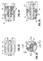
- a distal portion 246c of first drive shaft 246a is threaded.
- a flag member 247 Disposed about the threaded distal portion is a flag member 247 which includes an internally threaded nut 247a and a post 247b.
- a channel 247c is formed or defined therein that is configured to receive post 247b.
- Channel 247c prevents rotation of the flag member 247.
- a sensor 248a is mounted on the first drive shaft 264a and disposed distally from flag member 247. When half sections 211a and 211b of shaft assembly 200 are mated with each other, a channel 248b is formed that accommodates sensor 248a and prevents axial movement of sensor 248a.
- Sensor 248a is a highly poled piezo crystal in the shape of a disk or ring. In alternative embodiments, sensor 248a may be a stack of highly poled piezo crystals. Highly poled piezo crystals are known to provide higher signals than ordinary piezo crystal.
- the sensor 248a During operation of the powered surgical instrument 100, as the forces remain steady during firing or other actions, the sensor 248a provides little or low electrical signals. As first drive shaft 246a is rotated, flag member 247 is advanced distally. When flag member 247 contacts sensor 248, the forces generated by such contact rise rapidly, causing a high electrical signal to be generated by sensor 248 and transmitted to a controller 502 (see FIG. 50 ) via conduit 248c.
- Articulating neck assembly 230 includes a proximal neck housing 232, a plurality of links 234 connected to and extending in series from proximal neck housing 232; and a distal neck housing 236 connected to and extending from a distal-most link of the plurality of links 234.
- Each link 234 includes cooperating knuckles and clevises formed on each of a proximal surface 234a and a distal surface 234b thereof.
- Proximal neck housing 232 includes knuckles and/or clevises that operatively engage with the knuckles and/or clevises of a proximal-most link.
- Distal neck housing 236 includes knuckles and/or clevises that operatively engage with the knuckles and/or clevises of a distal-most link.
- the knuckles and clevises of adjacent neck housings 232, 236 and links 234 operatively engage with one another to define a direction and a degree of articulation of neck assembly 230.
- Neck assembly 230 is configured to enable end effector 400 to move between a substantially linear configuration and a substantially angled, off-axis or articulated configuration. In accordance with the present disclosure, it is contemplated that neck assembly 230 is capable of articulating in a single plane and is capable of articulating approximately 90°, and even greater than 90°.
- Each link 234 defines a first lumen 234c (see FIG. 12 ) therein for passage of a first drive cable 266 therethrough; a first pair of opposed lumens 234d 1 , 234d 2 , for passage of a pair of articulation cables 262, 264 therethrough; and a second lumen 234e for passage of a second drive cable 268 therethrough.
- first and second lumens 234c, 234e are diametrically opposed to one another and offset 90° relative to lumens 234d 1 , 234d 2 .
- Each of first drive cable 266 and second drive cable 268 includes a proximal end keyed to a distal end of respective first output drive shaft 246a and second output drive shaft 258a.
- Each of first and second drive cables 266, 268 is fabricated from a material that is both flexible and torsionally stiff (capable of transmitting rotational forces or torque), such as, for example, stainless steel and the like.
- proximal neck housing 232 of neck assembly 230 supports an articulation assembly 270 configured and adapted to impart articulation to neck assembly 230 and/or end effector 400.
- Articulation assembly 270 includes a pair of opposed gear racks 272, 274 engaged with and on opposed sides of a pinion gear 276.
- Racks 272, 274 are axially slidably supported in proximal neck housing 232 and pinion gear 276 is rotatably supported in proximal neck housing 232.
- rack 274 is attached to a threaded shaft 272a extending proximally therefrom and that is in threaded engagement with a distal end of an internally threaded nut 278.
- Threaded nut 278 is rotatably supported and axially fixed within a pocket 232a formed in proximal neck housing 232.
- a proximal end of threaded nut 278 is keyed to a distal end of third drive shaft 228. While threaded shaft 272a is shown extending from rack 274, it is understood, and within the scope of the present disclosure, that the threaded shaft may extend from rack 272 without departing from the principles of the present disclosure.
- Articulation cables 262, 264 include proximal ends that are secured to and extend from a respective distal end of racks 272, 274. Each articulation cable 262, 264 includes a distal end that extends through respective opposed lumens 234d 1 , 234d 2 of links 234 and that is secured to or anchored in distal neck housing 234.
- third drive shaft 228 is rotated in a first direction, as described above, to rotate threaded nut 278 and axially displace threaded shaft 272a distally to axially displace rack 274 distally (see FIG. 16 ).
- rack 274 As rack 274 is displaced axially, in a distal direction, rack 274 causes pinion gear 276 to be rotated and to thus act on rack 272, to axially displace rack 272 in a proximal direction.
- rack 272 causes articulation cable 262 to be drawn in a proximal direction and thereby articulate neck assembly 230, as illustrated in FIG. 16 .
- Neck assembly 230 is permitted to articulate since axially displacement of rack 274, in a distal direction, results in axial, distal displacement of articulation cable 264.
- Distal neck housing 236 supports a first gear train 280 and a second gear train 290.
- First gear train 280 functions to transmit a rotation of first drive cable 266 to end effector 400.
- Second gear train 290 functions to transmit a rotation of second drive cable 268 to end effector 400.
- first gear train 280 of distal neck housing 236 includes a first spur gear 282a rotatably supported in distal neck housing 236 and keyed to a distal end of first drive cable 266 of shaft assembly 200.
- First gear train 280 of distal neck housing 236 further includes a second spur gear 282b rotatably supported in distal neck housing 236 and engaged with first spur gear 282a.
- First gear train 280 of distal neck housing 236 also includes a third spur gear 282c rotatably supported in distal neck housing 236 and engaged with second spur gear 282b.
- Third spur gear 282c includes a bore 282d formed along a central axis thereof that is configured for mating receipt of a drive axle 426 of end effector 400 (see FIG. 26 ).
- first spur gear 282a includes 8 teeth; second spur gear 282b includes 10 teeth; and third spur gear 282c includes 8 teeth.
- an input rotation of first drive cable 266 is converted to an output rotation of third spur gear 282c of distal neck housing 236 by a ratio of 1:1.
- first gear train 280 is provided to rotatably and mechanically connect first drive cable 266 to drive axle 426 of end effector 400.
- first drive cable 266 is rotated, due to a rotation of first output drive shaft 246a (as described above), said rotation is transmitted to first spur gear 282a of first gear train 280.
- third spur gear 282c is rotated due to the interengagement of first spur gear 282a and third spur gear 282c by second spur gear 282b.
- third spur gear 282c is rotated, when end effector 400 is connected to shaft assembly 200, and specifically, third spur gear 282c is connected to drive axle 426 of end effector 400, a rotation of third spur gear 282c results in rotation of drive axle 426 of end effector 400 and actuation of end effector 400.
- second gear train 290 of distal neck housing 236 includes a first spur gear 292a rotatably supported in distal neck housing 236 and keyed to a distal end of second drive cable 268 of shaft assembly 200.
- Second gear train 290 of distal neck housing 236 further includes a second spur gear 292b rotatably supported in distal neck housing 236 and engaged with first spur gear 292a.
- Second gear train 290 of distal neck housing 236 also includes a non-circular shaft 292c extending from second spur gear 292b (see FIG. 21 ).
- Non-circular shaft 292c is keyed to a rotation hub 294 such that rotation of non-circular shaft 292c results in rotation of rotation hub 294.
- Rotation hub 294 is provided between a shaft of third spur gear 282c of first gear train 280, that defines the bore 282d thereof, and non-circular shaft 292c, rotation hub 294 transmitting relative rotation of third spur gear 282c of first gear train 280 to non-circular shaft 292c of second gear train 290.
- first spur gear 292a includes 8 teeth (which functions as the input); and second spur gear 292b includes 10 teeth.
- an input rotation of second drive cable 268 is converted to an output rotation of rotation hub 294.
- the gear ratio for this is 1:0.8.
- second gear train 290 is provided to rotatably and mechanically connect second drive cable 268 to rotation hub 294 of distal neck housing 236 of neck assembly 230.
- Shaft assembly 200 further includes an end effector coupling assembly 310 supported at a distal end of distal neck housing 236 of articulating neck assembly 230.
- End effector coupling assembly 310 includes a collar 312 rotatably supported on and extending distally from distal neck housing 236 and being biased to a first radial position.
- Collar 312 is rotatable from a first radial position to a second radial position, wherein end effector 400 is matable to end effector coupling assembly 310, and returns, by way of the bias, to the first radial position, to lock end effector 400 to shaft assembly 200.
- collar 312 includes at least one nub 312a extending radially inward from inner surface thereof for receipt in a respective complementary structure 422a formed in an outer surface of end effector 400 to connect end effector 400 to shaft assembly 200 in the manner of a bayonet-type connection.
- Other forms of connection are contemplated, such as, detents, threaded connections, etc.
- shaft assembly 200 includes a cable tensioning assembly 320.
- Cable tensioning assembly 320 includes a clevis 322 slidably supported in proximal neck housing 232, for axial displacement therewithin.
- Clevis 322 rotatably supports pinion gear 276 of articulation assembly 270.
- Cable tensioning assembly 320 includes an adjustment screw 324, rotatably supported in proximal neck housing 232 and retained against axial displacement. Adjustment screw 324 is threadably connected to clevis 322 such that rotation of adjustment screw 324 results in axial displacement of clevis 322.
- an operator rotates adjustment screw 324 in a direction so as to axially displace clevis 322 in a proximal direction.
- clevis 322 pulls on pinion gear 276 of articulation assembly 270.
- pinion gear 276 acts on racks 272, 274 to draw racks 272, 274 in a proximal direction.
- articulation cables 262, 264 are caused to be tensioned.
- a set screw 328 may be provided to fix the position of adjustment screw 324 and help to maintain articulation cables 262, 264 tensioned.
- an end user of shaft assembly 200 may be able to access adjustment screw 324 and re-tension articulation cables 262, 264 as needed or necessary.
- End effector 400 is shown and described. End effector 400 is configured and adapted to apply a plurality of linear rows of fasteners 433.
- the fasteners are of various sizes, and, in certain embodiments, the fasteners have various lengths or rows, e.g., about 30, 45 and 60 mm in length.
- end effector 400 includes a mounting portion 420 ( Fig. 28 ) configured for selective connection to end effector coupling assembly 310 of shaft assembly 200.
- End effector 400 further includes a jaw assembly 430 connected to and extending distally from mounting portion 420.
- Jaw assembly 430 includes a lower jaw 432 pivotally connected to mounting portion 420 and being configured to selectively support a cartridge assembly 410 therein, and an upper jaw 442 secured to mounting portion 420 and being movable, relative to lower jaw 432, between approximated and spaced apart positions.
- mounting portion 420 includes a coupling member 422 secured to a proximal end thereof.
- Coupling member 422 defines a substantially J-shaped channel 422a (see FIGS. 26-28 ) formed in a radial outer surface thereof that is configured and dimensioned for selective connection with complementary structure formed on or extending radially inward from collar 312 of end effector coupling assembly 310, as described above.
- Coupling member 422 further includes a pair of spaced apart alignment stems 424a, 424b projecting proximally therefrom, for receipt in respective alignment bores 310a, 310b formed in a distal surface of end effector coupling assembly 310.
- the alignment stems 424a, 424b along with the alignment bores 310a, 310b are used to align and couple end effector 400 to end effector coupling assembly 310 of shaft assembly 200.
- the nub 312a of collar 312 and the J-shaped channel 422a of coupling member 422 may define a conventional bayonet-type coupling which facilitates quick and easy engagement and removal of end effector 400 from shaft assembly 200 before, during or after a surgical procedure.
- Mounting portion 420 further includes, as seen in FIGS. 26 , 28-31 , 34 and 35 a drive axle 426 rotatably supported therein.
- Drive axle 426 includes a multi-faceted, proximal head 426a projecting proximally from coupling member 422 and being configured for mating engagement with third spur gear 282c of first gear train 280 of distal neck housing 236 and first gear train system 240 of shaft assembly 200, when end effector 400 is coupled to shaft assembly 200.
- Drive axle 426 further includes multi-faceted, a distal head 426b projecting distally from coupling member 422 and being configured for mating engagement with a threaded drive shaft 464 supported in lower jaw 432 of jaw assembly 430.
- Drive axle 426 functions to transmit rotational drive forces from third spur gear 282c of first gear train 280 of distal neck housing 236 and first gear train system 240 of shaft assembly 200, which defines an axis of rotation, to drive screw 464 of lower jaw 432 of jaw assembly 430, which defines an axis of rotation that is different than the axis of rotation of third spur gear 282c.
- lower jaw 432 of jaw assembly 430 includes a drive screw 464 rotatably supported therein and extending substantially an entire length thereof.
- Drive screw 464 includes a female coupling member 464a supported on a proximal end thereof and being configured for receipt of multi-faceted, distal head 426b of drive axle 426.
- Drive screw 464 is axially and laterally fixed within lower jaw 432 of jaw assembly 430 by a thrust plate 465, or the like, which is secured to jaw assembly 430 and at least partially extends into an annular channel 464a formed in drive screw 464. In operation, rotation of drive axle 426 results in concomitant rotation of drive screw 464.
- end effector 400 includes a drive beam 466 slidably supported in lower jaw 432 of jaw assembly 430.
- Drive beam 466 includes a substantially I-shaped cross-sectional profile and is configured to approximate lower jaw 432 and upper jaw 442, and to axially displace an actuation sled 468 through lower jaw 432. As seen in FIG.
- drive beam 466 includes a vertically oriented support strut 466a; a lateral projecting member 466b formed atop support strut 466a and being configured to engage and translate with respect to an exterior camming surface of upper jaw 442 to progressively close jaw assembly 430; and a retention foot 466c having an internally threaded bore for threadable connection to threaded drive shaft 464. Since drive beam 466 is prevented from rotation by the engagement of strut 466a and/or cam member 466b with upper jaw 442, as drive screw 464 is rotated, retention foot 466c, and in turn, drive beam 466 is axially translated relative to lower jaw 432.
- Drive beam 466 includes a lock clip 467 extending distally from strut 466a.
- Lock clip 467 defines a hook 467a configured to engage a window 450c formed in a knife sled 450, as will be discussed in greater detail below. Hook 467a of lock clip 467 is biased to extend away from knife sled 450.
- the drive beam 466 Prior to firing the cartridge assembly 410, the drive beam 466 is at a proximal-most position in lower jaw 432 and actuation sled 418 and knife sled 450 are at a proximal-most position in cartridge body 412, as seen in FIGS. 36 and 37 .
- Lock clip 467 prior to firing, is disengaged from window 450c of knife sled 450 and extends into a relief 412e defined in a wall of knife slot 412b.
- Lower jaw 432 is in the form of a channel and is configured and adapted to selectively receive a disposable staple cartridge assembly 410 therein.
- Staple cartridge assembly 410 includes a cartridge body 412 defining a plurality of rows of staple retaining slots 412a and a longitudinally extending knife slot 412b disposed between pairs of rows of staple retaining slots 412a.
- Staple cartridge assembly 410 also includes a plurality of staples 433 disposed, one each, in the plurality of retaining slots 412a.
- Staple cartridge assembly 410 further includes a plurality of staple pushers 416 supported therein, wherein the staple pushers 416 are aligned one each within retaining slots 412a such that a single staple pusher 416 is positioned under a respective staple 433 which is retained within slot 412a.
- Staple pushers 416 may be formed such that they are attached to each other in a pusher member having groups of two or three pushers, wherein the pusher member may have offset oriented pushers.
- One or more actuating surfaces is provided on a lower surface of the pusher member (not shown).
- Staple cartridge assembly 410 includes an actuation sled 418 slidably supported against a lower surface of cartridge body 412 and being engageable by drive beam 466.
- Actuation sled 418 includes upstanding cam wedges 418a configured to exert a driving force on staple pushers 416, by contacting the actuating surfaces, which drives staples 414 from staple cartridge assembly 410, as described in greater detail below.
- Cartridge body 412 defines a plurality of spaced apart longitudinal channels 412c (see FIG. 36 ) extending therethrough to accommodate the upstanding cam wedges 418a of actuation sled 418.
- Channels 412c communicate with the plurality of retaining slots 412a within which the plurality of staples 433 and pushers 416 are respectively supported.
- staple cartridge assembly 410 further includes a knife sled 450 slidably supported within knife slot 412b of cartridge body 412 and being interposed between drive beam 466 and actuation sled 468.
- knife sled 450 defines a knife blade 450a extending from an upper surface thereof and oriented distally, wherein knife blade 450a extends through knife slot 412b of cartridge body 412.
- Knife sled 450 includes a lock-out spring 451 extending distally therefrom for engaging a lock-out notch 412d formed in a surface of cartridge body 412 (see FIG. 37 ), as will be discussed in greater detail below.
- Lock-out spring 451 is biased toward lock-out notch 412d. Prior to firing of cartridge assembly 410, with actuation sled 418 and knife sled 450 at a proximal-most position in cartridge body 412, as seen in FIG. 34-37 , lock-out spring 451 is blocked by actuation sled 418 from entering lock-out notch 412d of cartridge body 412.
- Staple cartridge assembly 410 includes a bottom cover or retainer 415 configured to maintain the plurality of staple pushers 416, actuation sled 418 and knife sled 450 within cartridge body 412.
- Retainer 415 supports and aligns the plurality of pushers 416 prior to engagement thereof by the actuation sled 418.
- the angled leading edges of cam wedges 418a of actuation sled 418 sequentially contact pushers 416, causing the pushers 416 to translate vertically within retaining slots 412a, urging the staples 433 therefrom.
- knife sled 450 severs tissue and retaining sutures that extend across knife slot 412b of cartridge body 412.
- drive beam 466 is advanced into contact with knife sled 450 and actuation sled 418 to distally advance or push knife sled 450 and actuation sled 418 through cartridge body 412 and lower jaw 432.
- drive beam 466 As drive beam 466 is continually driven in the distal direction, drive beam 466 maintains contact with knife sled 450 and actuation sled 418, thereby pushing knife sled 450 and actuation sled 418 in the distal direction and to approximate lower jaw 430 and upper jaw 440, as laterally projecting member 466b of drive beam 466 pushes down on the exterior camming surface of upper jaw 440, to eject the staples 414 and fasten tissue, and to simultaneously dissect tissue with knife blade 450a. Knife sled 450, actuation sled 418 and drive beam 466 travel through cartridge body 412 thereby fastening and severing tissue.
- hook 467a of lock clip 467 exits relief 412e and is cammed into window 450c of knife sled 450 as hook 467a enters knife slot 412b of cartridge body 412.
- Drive screw 464 is rotated until actuation sled 418, knife sled 450 and drive beam 466 reach a distal-most end of cartridge body 412 and/or lower jaw 432, for a complete firing.
- drive screw 464 is rotated in an opposite direction to retract drive beam 466. Since and knife sled 450 is connected to drive beam 466 by lock clip 467, as described above, as drive beam 466 is retracted, knife sled 450 is also retracted. Actuation sled 418 will tend to remain at a distal or distal-most position due to its frictional engagement in channels 412c of cartridge body 412 (see FIG. 40 ). Drive screw 464 is rotated until drive beam 466 and knife sled 450 are returned to the proximal-most position.
- lock-out spring 451 is biased toward lock-out notch 412d, as seen in FIG. 43
- lock-out spring 451 which is attached to knife sled 450, is now free to enter lock-out notch 412d and prevent knife sled 450 and/or drive beam 466 being re-advanced, thereby locking-out staple cartridge assembly 410.
- Upper jaw 442 of jaw assembly 430 functions as an anvil against which the staples 433 form when actuation sled 418 is advanced during a firing of surgical instrument 100.
- upper jaw 442 includes an anvil plate 443, secured to a cover housing 444, in juxtaposed relation to staple cartridge assembly 410.
- Anvil plate 443 defines a plurality of staple forming pockets (not shown), arranged in longitudinally extending rows that cooperate with the rows of staple retaining slots 412a of staple cartridge assembly 410, when staple cartridge assembly 410 is disposed in lower jaw 432.
- Lower jaw 432 is pivotably connected to mounting portion 420 by way of appropriate pivot pins 445 or the like extending through a pair of spaced apart shoulders 432a, 432b disposed near a proximal end thereof. Shoulders 432a, 432b of lower jaw 432 extend into reliefs or the like formed in mounting portion 420.
- jaw assembly 430 includes at least one biasing member 447, in the form of a compression spring or the like, disposed between each shoulder 432a, 432b of lover jaw 432 and a bearing surface of mounting portion 420 such that lower jaw 432 is spaced from upper jaw 442, until closed, to maintain jaw assembly 430 in an open position.
- biasing members 447 are biased (i.e., compressed) between shoulders 432a, 432b of lower jaw 432 and the bearing surface of mounting portion 420.
- drive screw 464 is rotated, in a second direction that is opposite the first direction, to withdraw drive beam 466 and knife sled 450, as described above.
- biasing members 447 begin to expand to press apart shoulders 432a, 432b of lower jaw 432 from the bearing surface of mounting portion 420 to separate the upper jaw 442 from the lower jaw 432 to open jaw assembly 430.
- cartridge body 412 of staple cartridge assembly 410 may be configured and adapted to selectively support a surgical buttress on a tissue contact surface thereof.
- cartridge body 412 of staple cartridge assembly 410 defines a proximal pair of recesses formed near a proximal end thereof and disposed, one each, on opposed sides of longitudinally extending knife slot 412b.
- Cartridge body 412 further defines a distal pair of recesses 412e formed near a distal end thereof and disposed, one each, on opposed sides of longitudinally extending knife slot 412b.
- the distal pair of recesses 412e is preferably non-circular and constricting or otherwise arranged so as to frictionally engage and/or pinch an anchor "S".
- cartridge body 412 further includes a surgical cartridge buttress "B1", pledget or the like operatively secured to an upper surface or tissue contacting surface thereof, by suture anchors "S1" and “S2", to overlie at least some of the plurality of staple retaining slots 412a and/or at least a portion of a length of longitudinally extending knife slot 412b.
- an anchor “S1” is cinched around a proximal portion of surgical cartridge buttress "B1” and each of the proximal pair of recesses and an anchor “S2” is cinched around a distal portion of the surgical cartridge buttress "B1" and each of the distal pair of recesses 412e.
- the anchors may comprise a surgical suture.
- a first end of suture anchor “S1” includes a knot, stop or the like (not shown) sized so as to not pass through one recess of the proximal pair of recesses and a second end of suture anchor “S1” passes over, and transversely across, surgical cartridge buttress "B1", at least once, and back through the other recess of the proximal pair of recesses.
- the second end of suture anchor “S1” may be pinched or cinched in the other recess of the proximal pair of recesses so as to anchor the second end of the suture anchor "S1" and secure the surgical cartridge buttress "B1" against the tissue contacting surface of cartridge body 412.
- a suture anchor "S2" is used to extend transversely across surgical cartridge buttress "B1” and into engagement with the distal pair of recesses 412e.
- Surgical cartridge buttress "B1" includes a proximal pair of notches formed in side edges aligned with the proximal pair of recesses of cartridge body 412, a distal pair of notches formed in side edges thereof aligned with the distal pair of recesses 412e of cartridge body 412, and a proximal notch formed in a proximal edge thereof aligned with longitudinally extending knife slot 412b when cartridge buttress "B1" is secured to cartridge body 412.
- Cartridge buttress "B1” further includes a tongue or tab extending from a distal edge thereof to facilitate with the attachment of cartridge buttress "B1" to cartridge body 412 during the assembly process.
- cartridge buttress "B1" may be reduced in a proximal portion thereof. It is further contemplated that the tongue is removed from cartridge buttress "B1" following securement of cartridge buttress "B1" to cartridge body 412 and prior to packaging or shipment.
- cartridge body 412 of staple cartridge assembly 410 includes a cartridge buttress release assembly 470 supported in and near a distal end of cartridge body 412.
- Release assembly 470 includes a retainer 472 supported in a distal end of cartridge body 412 at a location near a distal end of longitudinally extending knife slot 412b and at least partially extending thereacross.
- Retainer 472 includes a body portion 472a, a boss 472b extending from a surface thereof, and defines a channel or recess 427c formed in a surface thereof and extending through a side thereof. When supported in cartridge body 412, recess 472c of retainer 472 is in registration with one of the pair of distal recesses 412e of cartridge body 412.
- Release assembly 470 further includes a pusher member 474 having a head portion 474a pivotally connected to boss 472b of retainer 472.
- Pusher member 474 further includes a first leg member 474b extending from head portion 474a and a second leg member 474c connected to a free end of first leg member 474b via a living hinge connection.
- Pusher member 474 further includes piston 474e connected to a free end of second leg member 474c via a living hinge connection. Piston 474e is slidably disposed and translatable within recess 472c of retainer 472.
- the pusher is a linkage assembly having a first link pivotably connected to the cartridge body at one end. The other end of the first link is pivotably connected to a first end of a second link. The opposite, second, end of the second link is confined in the recess of the retainer.
- release assembly 470 includes an unactuated configuration wherein piston 474e does not extend into or overlie the respective one of the pair of distal recesses 412e of cartridge body 412, and first leg member 474b and second leg member 474c are angled with respect to one another and project proximally along longitudinally extending knife slot 412b of cartridge body 412. It is contemplated that release assembly 470 may include a friction fit or snap fit feature for maintaining and/or retaining release assembly 470 in the locking or anchoring configuration at all times following the manufacturing/assembly process and prior to a complete firing of surgical instrument 100.
- release assembly 470 includes an actuated configuration wherein piston 474e extends into or overlies the respective one of the pair of distal recesses 412d of cartridge body 412 in operative registration therewith, and first leg member 474b and second leg member 474c are extended substantially along a common axis.
- knife blade 450a of knife sled 450 slices through a central section of proximal suture anchor "S1", thereby freeing the proximal end of the surgical cartridge buttress "B1" from cartridge body 412.
- actuation sled 418 contacts the living hinge connection between first leg member 474b and second leg member 474c.
- actuation sled 418 presses against the living hinge connection, causing first leg member 474b and second leg member 474c to extend.
- piston 474e is translated through recess 472c of retainer 472.
- piston 474e engages the second end of suture anchor "S2" and urges the second end of suture anchor "S2" out of the distal recess 412d of cartridge body 412 that is in registration therewith to release the second end of suture anchor "S2" therefrom.
- the distal end of the surgical cartridge buttress "B1" is free to separate from the tissue contacting surface of cartridge body 412.
- upper jaw 442 further includes a surgical anvil buttress "B2", pledget or the like operatively secured to an upper surface or tissue contacting surface thereof, by anchors "S3" and “S4", to overlie at least some of the plurality of staple forming pockets and/or at least a portion of a length of a longitudinally extending knife slot of anvil plate 443.
- the anchors may comprise surgical sutures.
- a suture anchor "S3" is cinched around a proximal portion of surgical anvil buttress "B2” and each of the proximal pair of recesses and a suture anchor "S4" is cinched around a distal portion of the surgical anvil buttress "B2” and each of a distal pair of recesses 443a formed in opposed side edges of anvil plate 443.
- a first end of suture anchor “S3” includes a knot, stop or the like (not shown) sized so as to not pass through one recess of the proximal pair of recesses and a second end of suture anchor “S3” passes over, and transversely across, surgical anvil buttress "B2", at least once, and back through the other recess of the proximal pair of recesses.
- the second end of suture anchor “S3” may be pinched or cinched in the other recess of the proximal pair of recesses so as to anchor the second end of the suture anchor "S3" and secure the surgical anvil buttress "B2" against the tissue contacting surface of anvil plate 443.
- a suture anchor "S4" is used to extend transversely across surgical anvil buttress "B2" and into engagement with the distal pair of recesses 443a.
- Surgical anvil buttress "B2" includes a proximal pair of notches formed in side edges aligned with the proximal pair of recesses of anvil plate 443, a distal pair of notches formed in side edges thereof aligned with the distal pair of recesses 443a of anvil plate 443, and a proximal notch formed in a proximal edge thereof aligned with longitudinally extending knife slot when anvil buttress "B2" is secured to anvil plate 443.
- Anvil buttress "B2” further includes a tongue or tab extending from a distal edge thereof to facilitate with the attachment of anvil buttress "B2" to anvil plate 443 during the assembly process. It is contemplated that the tongue is removed from anvil buttress "B2” following securement of anvil buttress "B2" to anvil plate 443 and prior to packaging or shipment.
- upper jaw 442 of jaw assembly 430 includes a suture release assembly 474 disposed between anvil plate 443 and cover housing 444 at a location in operative registration with a distal pair of side recesses 443a.
- Suture release assembly 474 includes a link arm 475 pivotally connected to anvil plate 443 and/or optionally cover housing 444.
- Link arm 475 includes a body portion 475a defining a pocket or recess 475c formed in a first side edge 475b thereof and a camming surface 475d defined substantially along an adjacent side or proximal edge thereof.
- Pocket 475c has a substantially arcuate, circular or rounded profile and defines an arcuate relief 475e in a side wall thereof.
- Link arm 475 includes a pivot pin extending from body portion 475a for pivotally connecting link arm 475 to upper jaw 442.
- Release assembly 474 further includes a pusher bar 477 pivotally connected to link arm 475 and slidably disposed between anvil plate 443 and cover housing 444.
- Pusher bar 477 includes a body portion 477a having a substantially rectangular configuration and a head 477b, extending from a corner of body portion 477a, and having a substantially circular or rounded configuration.
- Head 477b of pusher bar 477 is configured and dimensioned for pivotable and/or rotatable connection in pocket 475c of link arm 475.
- Head 477b of pusher bar 477 includes a stop member 477d projecting from a side edge thereof and into arcuate relief 475e of pocket 475c of link arm 475.
- a relative distance of rotation of pusher bar 477 relative to link arm 475 is determined by a relative length of arcuate relief 475e and a relative width of stop member 477d.
- suture release assembly 474 includes an unactuated configuration wherein pusher bar 477 does not extend into or overlie the respective one of the pair of distal recesses 443a in operative registration therewith, and a longitudinal axis of link arm 475 is oriented substantially parallel with a longitudinal axis of upper jaw 442. It is contemplated that suture release assembly 474 may include a friction fit or snap fit feature for maintaining and/or retaining suture release assembly 474 in the locking or anchoring configuration at all times following the manufacturing/assembly process and prior to a complete firing of the surgical stapling apparatus.
- suture release assembly 474 includes an actuated configuration wherein pusher bar 477 extends into or overlies the respective one of the pair of distal recesses 443a in operative registration therewith, and a longitudinal axis of link arm 475 is oriented substantially transverse to the longitudinal axis of upper jaw 442.
- actuation sled 418 contacts camming surface 475d of link arm 475, thus urging link arm 475 to rotate or pivot around the pivot pin and, in turn, urging pusher bar 477 to translate in the direction of the slot.
- pusher bar 477 comes into contact with and urges the second end of suture "S4" out of the distal recess 443a that is registration therewith to release the second end of suture "S4" therefrom.
- the distal end of the surgical anvil buttress "B2" is free to separate from the tissue contacting surface of anvil plate 443.
- Exemplary surgical buttresses "B" for use with the staple cartridge assembly 410 and/or anvil plate 443 disclosed herein are shown and described in commonly assigned U.S. Patent Nos. 5,542,594 , 5,908,427 , 5,964,774 , 6,045,560 , and 7,823,592 ; commonly assigned U.S. Application Serial No. 12/579,605, filed on October 15, 2009 (now U.S. Patent Publication No. 20110089220 ); commonly assigned U.S. Application Serial No. 11/241,267, filed on September 30, 2005 (now U.S. Patent Publication No. 2006/0085034 ); and U.S. Application Serial No. 13/097,194, filed on April 29, 2011 , entitled "Surgical Stapling Apparatus;" the entire contents of each of which being incorporated herein by reference.
- Surgical buttresses “B” may be fabricated from a suitable biocompatible and bioabsorbable material. Surgical buttresses “B” may be fabricated from a non-absorbent material which does not retain fluid. Surgical buttresses “B” may be fabricated from "BIOSYN” made from GLYCOMER 631 (a block copolymer), a synthetic polyester composed of glycolide, dioxanone and trimethylene carbonate.
- One block of the resulting copolymer contains randomly combined units derived from p-dioxanone (1,4-dioxan-2-one) and trimethylene carbonate (1,3-dioxan-2-one).
- the second block of the copolymer contains randomly combined units derived from glycolide and p-dioxanone.
- the resulting polyester is an ABA triblock terpolymer possessing about 60% glycolide, about 14% dioxanone, and about 26% trimethylene carbonate.
- the surgical buttress may comprise polymers or copolymers of glycolide, lactide, poly caprolactone, trimethylene carbonate, dioxanone, caprolactone, and may be molded, extruded, etc. into a desired shape, or formed into a knitted, woven, braided, non-woven or felted material.
- End stop detection system includes a controller 502.
- Controller 502 receives an input from input device 504 (e.g., actuation of a trigger, lever, or button) and controls motor 506 based on the input.
- Motor 506 causes first drive member 246a to rotate in a first direction causing the flag member 247 to translate axially along first drive member 246a.
- sensor 248a provides a high electrical signal to controller 502 causing controller 502 to stop motor 506.
- FIG. 51 depicts an end stop detection method based on an algorithm stored in controller 502.
- the process begins with step s602, where the powered surgical instrument 100 is activated.
- the motor 506 is controlled so that the first drive member 246a is rotated in a first direction causing flag member 247 to translate distally along first drive member 246a.
- controller 502 determines whether flag member 247 has contacted sensor 248a based on whether the controller received a high electrical signal from sensor 248a. If controller 502 did not receive a high electrical signal from sensor 248a, the process returns to step s604. If controller 502 receives a high electrical signal from sensor 248a, the process proceeds to step s608 where motor 506 is stopped.
- step s610 a determination is made whether a new end effector 400 is needed in step s610. Such determination may be based automatically on a surgical plan stored in controller 502 or may be inputted by a clinician. If a new end effector is not needed, the process ends. If a new end effector 400 is needed, the process proceeds to step s612 where the controller 502 identifies the type of end effector 400 to be attached. Such identification may be inputted by a clinician, based on the surgical plan stored in controller 502, or based on an identification device on end effector 400 such as a bar code or a radio-frequency identification (RFID) tag.
- RFID radio-frequency identification
- controller 502 controls motor 506 to rotate the first drive member 246a in a second direction, opposite the first direction, for a predetermined amount of time.
- the predetermined time corresponds to the type of end effector and may be obtained from a table stored in a memory 502a of controller 502.
- Such rotation of the first drive member 246a in the second direction causes flag member 247 to translate proximally.
- the flag member 247 can be positioned so that the distance the between the flag member 247 and the sensor 248a corresponds to the end stop distance of the identified end effector 400.
- steps s616 the identified end effector 400 is attached to the powered surgical instrument 100 and the process proceeds to step s602.
- surgical instrument 100 and/or cartridge assembly 410 need not apply staples but rather may apply two part fasteners as is known in the art.
- the length of the linear row of staples or fasteners may be modified to meet the requirements of a particular surgical procedure.
- the length of the linear row of staples and/or fasteners within a staple cartridge assembly may be varied accordingly. Therefore, the above description should not be construed as limiting, but merely as exemplifications of preferred embodiments. Those skilled in the art will envision other modifications within the scope and spirit of the claims appended thereto.
Abstract
Description
- This application claims the benefit of and priority to
U.S. Provisional Patent Application No. 61/940,004, filed February 14, 2014 - The present disclosure relates to surgical apparatus, devices and/or systems for performing endoscopic surgical procedures and methods of use thereof. More specifically, the present disclosure relates to electromechanical, hand-held surgical apparatus, devices and/or systems configured for use with removable disposable loading units and/or single use loading units for clamping, cutting and/or stapling tissue.
- A number of surgical device manufacturers have developed product lines with proprietary drive systems for operating and/or manipulating electromechanical surgical devices. Some electromechanical surgical devices include a handle assembly, which is reusable, and replaceable loading units and/or single use loading units or the like that are selectively connected to the handle assembly prior to use and then disconnected from the handle assembly following use, in order to be disposed of or in some instances sterilized for re-use.
- The replaceable loading units and/or single use loading units may include staples of various sizes and the staples may be arranged in one or more configurations. After firing the stapler with a replaceable loading unit, the user may remove the empty loading unit, select and attach to the stapler another loading unit having staples of the same or different size and the same or different staple arrangement, and fire the stapler again. This process may be performed repeatedly during a surgical procedure.
- The loading units have an end stop which is an indication that all staples have been fired. Rapid detection of the end stop is important to prevent damage to the surgical device. During a surgical procedure, the stapler often detects an end stop of the end-effector assembly by measuring the current from the motor. However, motor current measurements may not be entirely reliable.
- Accordingly, a need exists for electromechanical surgical apparatus, devices and/or systems that are capable of rapidly and accurately detecting an end stop of an end effector assembly.
- In an embodiment of the present disclosure, an electromechanical surgical system is provided. The system includes a hand-held surgical instrument including an instrument housing defining a connecting portion for selectively connecting with a shaft assembly. The system also includes an end effector configured to perform at least one function. The shaft assembly is arranged for selectively interconnecting the end effector and the hand-held surgical instrument. The shaft assembly includes a drive member, a flag member configured to translate axially along the first drive member, and a sensor disposed about the first drive member. The sensor provides a signal indicating that the end effector has reached an end stop when the flag member contacts the sensor.
- In some aspects, the flag member includes a post and the shaft assembly includes a channel configured to receive the post of the flag member. The channel is configured to prevent rotational movement of the flag member.
- In another aspect, the shaft assembly includes a channel configured to receive the sensor, where the channel is configured to prevent axial movement of the sensor.
- In yet another aspect, the system also includes a controller, wherein the sensor provides the signal to the controller indicating that the end stop of the end effector has been reached. The system also includes a motor, wherein the controller stops the motor when the controller receives the signal from the sensor.
- In aspects of the system, the sensor may include a highly poled piezo crystal or a stack of highly poled piezo crystals.
- In another embodiment of the present disclosure, an end stop detection method for a powered surgical instrument having a hand-held surgical instrument, an end effector and a shaft assembly including a drive member, a flag member, and a sensor is provided. The method includes controlling a motor within the hand-held surgical instrument to cause the drive member to rotate in a first direction thereby causing the flag member to translate distally along the drive member. The instrument determines if the flag member contacts the sensor and stops the motor if the flag member contacts the sensor.
- In some aspects, after the motor is stopped, the end effector is removed. The instrument then determines if a new end effector is needed based on a user input or a predetermined surgical plan. If a new end effector is needed, a type of end effector to be attached to the shaft assembly as the new end effector is identified. Then the motor is controlled to cause the drive member to rotate in a second direction opposite the first direction thereby causing the flag member to translate proximally along the drive member. The drive member is rotated for a predetermined amount of time based on the type of end effector to be attached to the shaft assembly. Then the new end effector is attached to the shaft assembly.
- Further details and aspects of exemplary embodiments of the present disclosure are described in more detail below with reference to the appended figures.
- Embodiments of the present disclosure are described herein with reference to the accompanying drawings, wherein:
-
FIG. 1 is a perspective view of an electromechanical surgical system according to an embodiment of the present disclosure; -
FIG. 2 is a perspective view, with parts separated, of the electromechanical surgical system ofFIG. 1 ; -
FIG. 3 is a rear, perspective view of a shaft assembly and a powered surgical instrument, of the electromechanical surgical system ofFIGS. 1 and2 , illustrating a connection therebetween; -
FIG. 4A is a perspective view, with parts separated, of the shaft assembly ofFIGS. 1-3 ; -
FIG. 4B is an enlarged view of the indicated area of detail ofFIG. 4A ; -
FIG. 4C is an enlarged view of the indicated area of detail ofFIG. 4B ; -
FIG. 5 is a perspective view, with parts separated of a transmission housing of the shaft assembly; -
FIG. 6 is a perspective view of a first gear train system that is supported in the transmission housing; -
FIG. 7 is a perspective view of a second gear train system that is supported in the transmission housing; -
FIG. 8 is a perspective view of a third drive shaft that is supported in the transmission housing; -
FIG. 9 is a perspective view of a neck assembly of the shaft assembly, shown in a straight orientation; -
FIG. 10 is a perspective view of the neck assembly ofFIG. 9 , shown in an articulated condition; -
FIG. 11 is a perspective view of the neck assembly ofFIGS. 9 and 10 , with a threaded nut separated therefrom; -
FIG. 12 is a perspective view, with parts separated, of the neck assembly ofFIGS. 9-11 ; -
FIG. 13 is a cross-sectional view of the neck assembly ofFIGS. 9-12 , as taken through 13-13 ofFIG. 9 ; -
FIG. 14 is a cross-sectional view of the neck assembly ofFIGS. 9-12 , as taken through 14-14 ofFIG. 10 ; -
FIG. 15 is a cross-sectional view of the neck assembly ofFIGS. 9-12 , as taken through 15-15 ofFIG. 14 ; -
FIG. 16 is an illustration of the neck assembly ofFIG. 13 , shown in an articulated condition; -
FIG. 17 is a perspective view of an articulation assembly; -
FIG. 18 is a further perspective view of the articulation assembly ofFIG. 17 ; -
FIG. 19 is a perspective view of a second gear train that is supported in a distal neck housing of the neck assembly; -
FIG. 20 is a perspective view, with parts partially separated, of a first gear train and the second gear train that are supported in a distal neck housing of the neck assembly; -
FIG. 21 is a perspective view, with parts partially separated, of the first gear train and the second gear train that are supported in a distal neck housing of the neck assembly; -
FIG. 22 is a cross-sectional view of the distal neck housing, as taken through 22-22 ofFIG. 19 ; -
FIG. 23 is a cross-sectional view of the distal neck housing, as taken through 23-23 ofFIG. 22 ; -
FIG. 24 is a cross-sectional view of the distal neck housing, as taken through 24-24 ofFIG. 22 ; -
FIG. 25 is a cross-sectional view of the distal neck housing, as taken through 25-25 ofFIG. 22 ; -
FIG. 26 is a rear, perspective view of the shaft assembly and an end effector, of the electromechanical surgical system ofFIGS. 1 and2 , illustrating a connection therebetween; -
FIG. 27 is a perspective view of the end effector, shown in a closed condition; -
FIG. 28 is a perspective view, with parts separated, of the end effector ofFIG. 27 ; -
FIG. 29 is a perspective view of a lower jaw of the end effector ofFIGS. 27 and28 ; -
FIG. 30 is a perspective view of a drive beam, a knife sled and an actuation sled of the end effector ofFIGS. 27-29 ; -
FIG. 31 is a further perspective view of the drive beam, the knife sled and the actuation sled of the end effector ofFIGS. 27-29 ; -
FIG. 32 is a cross-sectional view as taken through 32-32 ofFIG. 31 ; -
FIG. 33 is a perspective view, with parts separated, of the drive beam, the knife sled and the actuation sled of the end effector ofFIGS. 27-29 ; -
FIG. 34 is a cross-sectional view of the end effector ofFIG. 27 , as taken through 34-34 ofFIG. 27 , illustrating the drive beam, the knife sled and the actuation sled in a proximal-most position; -
FIG. 35 is an enlarged view of the indicated area of detail ofFIG. 34 ; -
FIG. 36 is a cross-sectional view of the end effector ofFIG. 27 , as taken through 36-36 ofFIG. 34 ; -
FIG. 37 is an enlarged view of the indicated area of detail ofFIG. 36 ; -
FIG. 38 is a further enlarged view illustrating the drive beam, the knife sled and the actuation sled in a distally advanced position; -
FIG. 39 is a cross-sectional view of the end effector ofFIG. 27 , as taken through 34-34 ofFIG. 27 , illustrating the drive beam, the knife sled and the actuation sled in a distal-most position; -
FIG. 40 is an enlarged view of the indicated area of detail ofFIG. 39 ; -
FIG. 41 is a cross-sectional view of a distal end of the end effector ofFIG. 27 , as taken through 34-34 ofFIG. 27 , illustrating the actuation sled in a distal-most position; -
FIG. 42 is a cross-sectional view of a proximal end of the end effector ofFIG. 27 , as taken through 34-34 ofFIG. 27 , illustrating the drive beam and the knife sled in a proximal position; -
FIG. 43 is a cross-sectional view of a proximal end of the end effector ofFIG. 27 , as taken through 34-34 ofFIG. 27 , illustrating the drive beam and the knife sled in a proximal-most position; -
FIG. 44 is a perspective view, with parts partially separated, of a release assembly supported in a distal end of a cartridge assembly of the end effector; -
FIG. 45 is a perspective view, with parts separated, of the release assembly ofFIG. 44 ; -
FIG. 46 is a plan view of the release assembly ofFIGS. 44 and 45 , shown in an unactuated condition; -
FIG. 47 is a plan view of the release assembly ofFIGS. 44 and 45 , shown in an actuated condition; -
FIG. 48 is a plan view of a release assembly supported in a distal end of an upper jaw of the end effector, illustrated in an unactuated condition; -
FIG. 49 is a plan view of the release assembly ofFIG. 48 , illustrated in an actuated condition; -
FIG. 50 is a system block diagram of an end stop detection system in accordance with an embodiment of the present disclosure; and -
FIG. 51 is a flow chart depicting an end stop detection method in accordance with an embodiment of the present disclosure. - Embodiments of the presently disclosed electromechanical surgical system, apparatus and/or device are described in detail with reference to the drawings, in which like reference numerals designate identical or corresponding elements in each of the several views. As used herein the term "distal" refers to that portion of the electromechanical surgical system, apparatus and/or device, or component thereof, that are farther from the user, while the term "proximal" refers to that portion of the electromechanical surgical system, apparatus and/or device, or component thereof, that are closer to the user.
- This description may use the phrases "in an embodiment," "in embodiments," "in some embodiments," or "in other embodiments," which may each refer to one or more of the same or different embodiments in accordance with the present disclosure. For the purposes of this description, a phrase in the form "A or B" means "(A), (B), or (A and B)". For the purposes of this description, a phrase in the form "at least one of A, B, or C" means "(A), (B), (C), (A and B), (A and C), (B and C), or (A, B and C)".
- The term "clinician" refers to any medical professional (i.e., doctor, surgeon, nurse, or the like) performing a medical procedure involving the use of embodiments described herein. As shown in the drawings and described throughout the following description, as is traditional when referring to relative positioning on a surgical instrument, the term "proximal" or "trailing" refers to the end of the apparatus which is closer to the clinician and the term "distal" or "leading" refers to the end of the apparatus which is further away from the clinician.
- The systems described herein may also utilize one or more controllers to receive various information and transform the received information to generate an output. The controller may include any type of computing device, computational circuit, or any type of processor or processing circuit capable of executing a series of instructions that are stored in a memory. The controller may include multiple processors and/or multicore central processing units (CPUs) and may include any type of processor, such as a microprocessor, digital signal processor, microcontroller, or the like. The controller may also include a memory to store data and/or algorithms to perform a series of instructions.
- Any of the herein described methods, programs, algorithms or codes may be converted to, or expressed in, a programming language or computer program. A "Programming Language" and "Computer Program" is any language used to specify instructions to a computer, and includes (but is not limited to) these languages and their derivatives: Assembler, Basic, Batch files, BCPL, C, C+, C++, Delphi, Fortran, Java, JavaScript, Machine code, operating system command languages, Pascal, Perl, PL1, scripting languages, Visual Basic, metalanguages which themselves specify programs, and all first, second, third, fourth, and fifth generation computer languages. Also included are database and other data schemas, and any other metalanguages. For the purposes of this definition, no distinction is made between languages which are interpreted, compiled, or use both compiled and interpreted approaches. For the purposes of this definition, no distinction is made between compiled and source versions of a program. Thus, reference to a program, where the programming language could exist in more than one state (such as source, compiled, object, or linked) is a reference to any and all such states. The definition also encompasses the actual instructions and the intent of those instructions.
- Any of the herein described methods, programs, algorithms or codes may be contained on one or more machine-readable media or memory. The term "memory" may include a mechanism that provides (e.g., stores and/or transmits) information in a form readable by a machine such a processor, computer, or a digital processing device. For example, a memory may include a read only memory (ROM), random access memory (RAM), magnetic disk storage media, optical storage media, flash memory devices, or any other volatile or non-volatile memory storage device. Code or instructions contained thereon can be represented by carrier wave signals, infrared signals, digital signals, and by other like signals.
- In embodiments described herein, a powered surgical device includes a piezo device used to detect the end stop of an end effector. A flag member is mounted on a drive shaft and translated axially upon actuation of the end effector. When the flag member contacts the piezo device, the piezo device provide a high electrical signal to a controller which turns off the motor controlling the drive shaft thereby stopping actuation of the end effector.
- Referring initially to
FIGS. 1-3 , an electromechanical, hand-held, powered surgical system, in accordance with an embodiment of the present disclosure is shown and generally designated 10. Electromechanicalsurgical system 10 includes a surgical apparatus or device in the form of an electromechanical, hand-held, poweredsurgical instrument 100 that is configured for selective attachment thereto of a plurality ofdifferent end effectors 400, via ashaft assembly 200, that are each configured for actuation and manipulation by the electromechanical, hand-held, poweredsurgical instrument 100. In particular,surgical instrument 100 is configured for selective connection withshaft assembly 200, and, in turn,shaft assembly 200 is configured for selective connection with any one of a plurality ofdifferent end effectors 400. - Reference may be made to International Application No.
PCT/US2008/077249, filed September 22, 2008 (Inter. Pub. No.WO 2009/039506 ) andU.S. Patent Application Serial No. 12/622,827, filed on November 20, 2009 U.S. Patent Application Publication No. 2011/0121049 ), the entire content of each of which are hereby incorporated herein by reference, for a detailed description of the construction and operation of exemplary electromechanical, hand-held, poweredsurgical instrument 100 - Generally, as illustrated in
FIGS. 1-3 ,surgical instrument 100 includes aninstrument housing 102 having alower housing portion 104, anintermediate housing portion 106 extending from and/or supported onlower housing portion 104, and anupper housing portion 108 extending from and/or supported onintermediate housing portion 106. Thesurgical instrument 100 has a controller for controlling certain functions of the surgical system, collecting data, and performing other functions.Instrument housing 102 defines a cavity therein in which a circuit board (not shown) and a drive mechanism (not shown) are situated. - The circuit board is configured to control the various operations of
surgical instrument 100, as will be set forth in additional detail below. In accordance with the present disclosure,instrument housing 102 provides a housing in which a rechargeable battery (not shown), is removably situated. The battery is configured to supply power to any of the electrical components ofsurgical instrument 100. -
Upper housing portion 108 ofinstrument housing 102 defines a nose or connectingportion 108a configured to accept a correspondingshaft coupling assembly 214 oftransmission housing 212 ofshaft assembly 200. As seen inFIG. 3 , connectingportion 108a ofupper housing portion 108 ofsurgical instrument 100 has acylindrical recess 108b that receivesshaft coupling assembly 214 oftransmission housing 212 ofshaft assembly 200 whenshaft assembly 200 is mated tosurgical instrument 100. The connectingportion 108a of thesurgical instrument 100 has at least one rotatable drive member. In particular, connectingportion 108a houses three rotatable drive members orconnectors instrument housing 102. -
Upper housing portion 108 ofinstrument housing 102 provides a housing in which the drive mechanism (not shown) is situated. The drive mechanism is configured to drive shafts and/or gear components in order to perform the various operations ofsurgical instrument 100. In particular, the drive mechanism is configured to drive shafts and/or gear components in order to selectively moveend effector 400 relative toshaft assembly 200; to rotateanvil assembly 200 and/orend effector 400, about a longitudinal axis "X" (seeFIGS. 1 and2 ), relative toinstrument housing 102; to move an upper jaw oranvil assembly 442 ofend effector 400 relative to a lower jaw orcartridge assembly 432 ofend effector 400; to articulate and/or rotate the shaft assembly; and/or to fire a stapling and cutting cartridge withincartridge assembly 432 ofend effector 400. - The
shaft assembly 200 has a force transmitting assembly for interconnecting the at least one drive member of the surgical instrument to at least one rotation receiving member of the end effector. The force transmitting assembly has a first end that is connectable to the at least one rotatable drive member and a second end that is connectable to the at least one rotation receiving member of the end effector. Whenshaft assembly 200 is mated tosurgical instrument 100, each of rotatable drive members orconnectors surgical instrument 100 couples with a correspondingrotatable connector sleeve FIGS. 3 and5 ). In this regard, the interface between corresponding first drive member orconnector 118 andfirst connector sleeve 218, the interface between corresponding second drive member orconnector 120 andsecond connector sleeve 220, and the interface between corresponding third drive member orconnector 122 andthird connector sleeve 222 are keyed such that rotation of each of drive members orconnectors surgical instrument 100 causes a corresponding rotation of the correspondingconnector sleeve shaft assembly 200. - The mating of drive members or
connectors surgical instrument 100 withconnector sleeves shaft assembly 200 allows rotational forces to be independently transmitted via each of the three respective connector interfaces. The drive members orconnectors surgical instrument 100 are configured to be independently rotated by the drive mechanism. In this regard, the controller has a function selection module (not shown) of the drive mechanism selects which drive member orconnector surgical instrument 100 is to be driven by an input drive component (not shown) of the drive mechanism. - Since each of drive members or
connectors surgical instrument 100 has a keyed and/or substantially non-rotatable interface withrespective connector sleeves shaft assembly 200, whenshaft assembly 200 is coupled tosurgical instrument 100, rotational force(s) are selectively transferred from the drive mechanism ofsurgical instrument 100 toshaft assembly 200, and on to endeffector 400, as will be discussed in greater detail below. - The selective rotation of drive member(s) or connector(s) 118, 120 and/or 122 of
surgical instrument 100 allowssurgical instrument 100 to selectively actuate different functions ofend effector 400. As will be discussed in greater detail below, selective and independent rotation of first drive member orconnector 118 ofsurgical instrument 100 corresponds to the selective and independent opening and closing ofend effector 400, and driving of a stapling/cutting component ofend effector 400. Also, the selective and independent rotation of second drive member orconnector 120 ofsurgical instrument 100 corresponds to the selective and independent articulation ofend effector 400 transverse to longitudinal axis "X" (seeFIG. 1 ). Additionally, the selective and independent rotation of third drive member orconnector 122 ofsurgical instrument 100 corresponds to the selective and independent rotation ofend effector 400 about longitudinal axis "X" (seeFIG. 1 ) relative toinstrument housing 102 ofsurgical instrument 100. - In accordance with the present disclosure, the drive mechanism may include a selector gearbox assembly (not shown); a function selection module (not shown), located proximal to the selector gearbox assembly, that functions to selectively move gear elements within the selector gearbox assembly into engagement with a second motor (not shown). The drive mechanism may be configured to selectively drive one of drive members or
connectors surgical instrument 100, at a given time. - As illustrated in
FIGS. 1 and2 ,instrument housing 102 supports a pair of finger-actuatedcontrol buttons control buttons instrument housing 102 includes, for each one of thecontrol buttons control buttons control button 124 is a respective Hall-effect switch (not shown) that is actuated upon the movement of a magnet within thecontrol button 124 upon the operatoractuating control button 124. The actuation of Hall-effect switch (not shown), corresponding to controlbutton 124, causes the circuit board to provide appropriate signals to the function selection module and the input drive component of the drive mechanism to closeend effector 400 and/or to fire a stapling/cutting cartridge withinend effector 400. - Also, located immediately proximal to
control button 126 is a respective Hall-effect switch (not shown) that is actuated upon the movement of a magnet (not shown) withincontrol button 126 upon the operatoractuating control button 126. The actuation of the Hall-effect switch, corresponding to controlbutton 126, causes the circuit board to provide appropriate signals to the function selection module and the input drive component of the drive mechanism to open/close end effector 400. - In addition, located immediately proximal to
rocker device 130 is a respective Hall-effect switch (not shown) that is actuated upon the movement of a magnet (not shown) withinrocker device 130 upon the operatoractuating rocker device 130. The actuation of the Hall-effect switch, corresponding torocker device 130, causes the circuit board to provide appropriate signals to the function selection module and the input drive component of the drive mechanism to rotateend effector 400 relative toshaft assembly 200 or rotateend effector 400 andshaft assembly 200 relative toinstrument housing 102 ofsurgical instrument 100. Specifically, movement ofrocker device 130 in a first direction causesend effector 400 and/orshaft assembly 200 to rotate relative toinstrument housing 102 in a first direction, while movement ofrocker device 130 in an opposite, e.g., second, direction causesend effector 400 and/orshaft assembly 200 to rotate relative toinstrument housing 102 in an opposite, e.g., second, direction. - Turning now to
FIGS. 1-26 ,shaft assembly 200 will be shown in detail and described.Shaft assembly 200 is configured to communicate the rotational forces of first, second and third rotatable drive members orconnectors surgical instrument 100 to endeffector 400. As mentioned above,shaft assembly 200 is configured for selective connection tosurgical instrument 100. - As seen in
FIGS. 1 ,2 and4A ,shaft assembly 200 includes an elongate, substantially rigid, outertubular body 210 having aproximal end 210a and adistal end 210b; atransmission housing 212 connected toproximal end 210a oftubular body 210 and being configured for selective connection tosurgical instrument 100; and an articulatingneck assembly 230 connected todistal end 210b ofelongate body portion 210. -
Transmission housing 212 is configured to house a pair of gear train systems therein for varying a speed/force of rotation (e.g., increase or decrease) of first, second and/or third rotatable drive members orconnectors surgical instrument 100 before transmission of such rotational speed/force to endeffector 400. -
Transmission housing 212 ofshaft assembly 200 is configured and adapted to connect to connectingportion 108a ofupper housing portion 108 ofsurgical instrument 100. As seen inFIGS. 3-5 ,transmission housing 212 ofshaft assembly 200 includes ashaft coupling assembly 214 supported at a proximal end thereof. - As seen in
FIGS. 5 and20-25 ,transmission housing 212 andshaft coupling assembly 214 rotatably support a first proximal orinput drive shaft 224a, a second proximal orinput drive shaft 226a, and athird drive shaft 228. -
Shaft coupling assembly 214 is configured to rotatably support first, second andthird connector sleeves connector sleeves connectors surgical instrument 100, as described above. Each ofconnector sleeves input drive shaft 224a, secondinput drive shaft 226a, andthird drive shaft 228. - Shaft
drive coupling assembly 214 includes a first, a second and athird biasing member third connector sleeves members proximal drive shaft 224a, secondproximal drive shaft 226a, andthird drive shaft 228.Biasing members respective connector sleeves connector sleeves connectors surgical instrument 100 whenshaft assembly 200 is connected tosurgical instrument 100. - In particular, first, second and
third biasing members respective connector sleeves shaft assembly 200 tosurgical instrument 100, if first, second and orthird connector sleeves connectors surgical instrument 100, first, second and/or third biasing member(s) 218a, 220a and/or 222a are compressed. Thus, when the drive mechanism ofsurgical instrument 100 is engaged, drive members orconnectors surgical instrument 100 will rotate and first, second and/or third biasing member(s) 218a, 220a and/or 222a will cause respective first, second and/or third connector sleeve(s) 218, 220 and/or 222 to slide back proximally, effectively coupling drive members orconnectors surgical instrument 100 to respective firstinput drive shaft 224a, secondinput drive shaft 226a, andthird drive shaft 228. - In use, during a calibration of
surgical instrument 100, each ofdrive connectors surgical instrument 100 is rotated and the bias on connector sleeve(s) 218, 220 and 222 properly seats connector sleeve(s) 218, 220 and 222 over therespective drive connectors surgical instrument 100 when the proper alignment is reached. -
Shaft assembly 200 includes a first and a secondgear train system transmission housing 212 andtubular body 210, andadjacent coupling assembly 214. As mentioned above, eachgear train system rotatable drive connectors surgical instrument 100 before transmission of such rotational speed/force to endeffector 400. - As seen in
FIGS. 5 and6 , firstgear train system 240 includes firstinput drive shaft 224a, and a first input driveshaft spur gear 242a keyed to firstinput drive shaft 224a. Firstgear train system 240 also includes afirst transmission shaft 244 rotatably supported intransmission housing 212, a first inputtransmission spur gear 244a keyed tofirst transmission shaft 244 and engaged with first input driveshaft spur gear 242a, and a first outputtransmission spur gear 244b keyed tofirst transmission shaft 244. Firstgear train system 240 further includes a firstoutput drive shaft 246a rotatably supported intransmission housing 212 and tubular body 110, and a first output driveshaft spur gear 246b keyed to firstoutput drive shaft 246a and engaged with first outputtransmission spur gear 244b. - In accordance with the present disclosure, first input drive
shaft spur gear 242a includes 10 teeth; first inputtransmission spur gear 244a includes 18 teeth; first outputtransmission spur gear 244b includes 13 teeth; and first output driveshaft spur gear 246b includes 15 teeth. As so configured, an input rotation of firstinput drive shaft 224a is converted to an output rotation of firstoutput drive shaft 246a by a ratio of 1:2.08. - As mentioned above, a proximal end of first
input drive shaft 224a is configured to supportfirst connector sleeve 218. - In operation, as first input drive
shaft spur gear 242a is rotated, due to a rotation of first connector sleeve 258 and firstinput drive shaft 224a, as a result of the rotation of the firstrespective drive connector 118 ofsurgical instrument 100, first input driveshaft spur gear 242a engages first inputtransmission spur gear 244a causing first inputtransmission spur gear 244a to rotate. As first inputtransmission spur gear 244a rotates,first transmission shaft 244 is rotated and thus causes first output driveshaft spur gear 246b, that is keyed tofirst transmission shaft 244, to rotate. As first output driveshaft spur gear 246b rotates, since first output driveshaft spur gear 246b is engaged therewith, first output driveshaft spur gear 246b is also rotated. As first output driveshaft spur gear 246b rotates, since first output driveshaft spur gear 246b is keyed to firstoutput drive shaft 246a, firstoutput drive shaft 246a is rotated. - As will be discussed in greater detail below,
shaft assembly 200, includingfirst gear system 240, functions to transmit operative forces fromsurgical instrument 100 to endeffector 400 in order to operate, actuate and/orfire end effector 400. - As seen in
FIGS. 5 and7 , secondgear train system 250 includes secondinput drive shaft 226a, and a second input driveshaft spur gear 252a keyed to secondinput drive shaft 226a. Secondgear train system 250 also includes afirst transmission shaft 254 rotatably supported intransmission housing 212, a first inputtransmission spur gear 254a keyed tofirst transmission shaft 254 and engaged with second input driveshaft spur gear 252a, and a first outputtransmission spur gear 254b keyed tofirst transmission shaft 254. - Second
gear train system 250 further includes asecond transmission shaft 256 rotatably supported intransmission housing 212, a second inputtransmission spur gear 256a keyed tosecond transmission shaft 256 and engaged with first outputtransmission spur gear 254b that is keyed tofirst transmission shaft 254, and a second outputtransmission spur gear 256b keyed tosecond transmission shaft 256. - Second
gear train system 250 additionally includes a secondoutput drive shaft 258a rotatably supported intransmission housing 212 andtubular body 210, and a second output driveshaft spur gear 258b keyed to secondoutput drive shaft 258a and engaged with second outputtransmission spur gear 256b. - In accordance with the present disclosure, second input drive
shaft spur gear 252a includes 10 teeth; first inputtransmission spur gear 254a includes 20 teeth; first outputtransmission spur gear 254b includes 10 teeth; second inputtransmission spur gear 256a includes 20 teeth; second outputtransmission spur gear 256b includes 10 teeth; and second output driveshaft spur gear 258b includes 15 teeth. As so configured, an input rotation of secondinput drive shaft 226a is converted to an output rotation of secondoutput drive shaft 258a by a ratio of 1:6. - As mentioned above, a proximal end of second
input drive shaft 226a is configured to supportsecond connector sleeve 220. - In operation, as second input drive
shaft spur gear 252a is rotated, due to a rotation ofsecond connector sleeve 260 and secondinput drive shaft 226a, as a result of the rotation of the secondrespective drive connector 120 ofsurgical instrument 100, second input driveshaft spur gear 252a engages first inputtransmission spur gear 254a causing first inputtransmission spur gear 254a to rotate. As first inputtransmission spur gear 254a rotates,first transmission shaft 254 is rotated and thus causes first outputtransmission spur gear 254b, that is keyed tofirst transmission shaft 254, to rotate. As first outputtransmission spur gear 254b rotates, since second inputtransmission spur gear 256a is engaged therewith, second inputtransmission spur gear 256a is also rotated. As second inputtransmission spur gear 256a rotates,second transmission shaft 256 is rotated and thus causes second outputtransmission spur gear 256b, that is keyed tosecond transmission shaft 256, to rotate. As second outputtransmission spur gear 256b rotates, since second output driveshaft spur gear 258b is engaged therewith, second output driveshaft spur gear 258b is rotated. As second output driveshaft spur gear 258b rotates, since second output driveshaft spur gear 258b is keyed to secondoutput drive shaft 258a, secondoutput drive shaft 258a is rotated. - As will be discussed in greater detail below,
shaft assembly 200, including secondgear train system 250, functions to transmit operative forces fromsurgical instrument 100 to endeffector 400 in order rotateshaft assembly 200 and/orend effector 400 relative tosurgical instrument 100. - As mentioned above and as seen in
FIGS. 5 and8 ,transmission housing 212 andshaft coupling assembly 214 rotatably support athird drive shaft 228.Third drive shaft 228 includes aproximal end 228a configured to supportthird connector sleeve 222, and adistal end 228b extending to and operatively connected to anarticulation assembly 270 as will be discussed in greater detail below. - As seen in
FIG. 4A , elongate, outertubular body 210 ofshaft assembly 200 includes afirst half section 211a and asecond half section 211b defining at least three longitudinally extending channels through outertubular body 210 whenhalf sections output drive shaft 246a, secondoutput drive shaft 258a, andthird drive shaft 228 as firstoutput drive shaft 246a, secondoutput drive shaft 258a, andthird drive shaft 228 extend fromtransmission housing 212 to articulatingneck assembly 230. Each of firstoutput drive shaft 246a, secondoutput drive shaft 258a, andthird drive shaft 228 are elongate and sufficiently rigid to transmit rotational forces fromtransmission housing 220 to articulatingneck assembly 230. - Turning to
FIGS. 4A-4C , adistal portion 246c offirst drive shaft 246a is threaded. Disposed about the threaded distal portion is aflag member 247 which includes an internally threadednut 247a and apost 247b. Whenhalf sections shaft assembly 200 are mated with each other, achannel 247c is formed or defined therein that is configured to receivepost 247b.Channel 247c prevents rotation of theflag member 247. Thus, whenfirst drive shaft 246a is rotated,flag member 247 is prevented from rotating, and in turn, is axially translated along thefirst drive shaft 246a.Flag member 247 is configured to indicate an end stop ofend effector 400 as will be described below. - A
sensor 248a is mounted on the first drive shaft 264a and disposed distally fromflag member 247. Whenhalf sections shaft assembly 200 are mated with each other, achannel 248b is formed that accommodatessensor 248a and prevents axial movement ofsensor 248a.Sensor 248a is a highly poled piezo crystal in the shape of a disk or ring. In alternative embodiments,sensor 248a may be a stack of highly poled piezo crystals. Highly poled piezo crystals are known to provide higher signals than ordinary piezo crystal. - During operation of the powered
surgical instrument 100, as the forces remain steady during firing or other actions, thesensor 248a provides little or low electrical signals. Asfirst drive shaft 246a is rotated,flag member 247 is advanced distally. Whenflag member 247 contacts sensor 248, the forces generated by such contact rise rapidly, causing a high electrical signal to be generated by sensor 248 and transmitted to a controller 502 (seeFIG. 50 ) viaconduit 248c. - Turning now to
FIGS. 4A and9-16 , articulatingneck assembly 230 is shown and described. Articulatingneck assembly 230 includes aproximal neck housing 232, a plurality oflinks 234 connected to and extending in series fromproximal neck housing 232; and adistal neck housing 236 connected to and extending from a distal-most link of the plurality oflinks 234. - Each
link 234 includes cooperating knuckles and clevises formed on each of aproximal surface 234a and adistal surface 234b thereof.Proximal neck housing 232 includes knuckles and/or clevises that operatively engage with the knuckles and/or clevises of a proximal-most link.Distal neck housing 236 includes knuckles and/or clevises that operatively engage with the knuckles and/or clevises of a distal-most link. The knuckles and clevises ofadjacent neck housings links 234 operatively engage with one another to define a direction and a degree of articulation ofneck assembly 230. -
Neck assembly 230 is configured to enableend effector 400 to move between a substantially linear configuration and a substantially angled, off-axis or articulated configuration. In accordance with the present disclosure, it is contemplated thatneck assembly 230 is capable of articulating in a single plane and is capable of articulating approximately 90°, and even greater than 90°. - Each
link 234 defines afirst lumen 234c (seeFIG. 12 ) therein for passage of afirst drive cable 266 therethrough; a first pair of opposed lumens 234d1, 234d2, for passage of a pair ofarticulation cables second lumen 234e for passage of asecond drive cable 268 therethrough. As seen inFIG. 12 , first andsecond lumens first drive cable 266 andsecond drive cable 268 includes a proximal end keyed to a distal end of respective firstoutput drive shaft 246a and secondoutput drive shaft 258a. Each of first andsecond drive cables - As seen in
FIGS. 13-16 ,proximal neck housing 232 ofneck assembly 230 supports anarticulation assembly 270 configured and adapted to impart articulation toneck assembly 230 and/orend effector 400.Articulation assembly 270 includes a pair of opposed gear racks 272, 274 engaged with and on opposed sides of apinion gear 276.Racks proximal neck housing 232 andpinion gear 276 is rotatably supported inproximal neck housing 232. - As seen in
FIGS. 12 ,13 and17 ,rack 274 is attached to a threadedshaft 272a extending proximally therefrom and that is in threaded engagement with a distal end of an internally threadednut 278. Threadednut 278 is rotatably supported and axially fixed within apocket 232a formed inproximal neck housing 232. A proximal end of threadednut 278 is keyed to a distal end ofthird drive shaft 228. While threadedshaft 272a is shown extending fromrack 274, it is understood, and within the scope of the present disclosure, that the threaded shaft may extend fromrack 272 without departing from the principles of the present disclosure. -
Articulation cables racks articulation cable links 234 and that is secured to or anchored indistal neck housing 234. - In operation, to articulate
neck assembly 230 in a first direction,third drive shaft 228 is rotated in a first direction, as described above, to rotate threadednut 278 and axially displace threadedshaft 272a distally to axially displacerack 274 distally (seeFIG. 16 ). Asrack 274 is displaced axially, in a distal direction, rack 274 causespinion gear 276 to be rotated and to thus act onrack 272, to axially displacerack 272 in a proximal direction. Asrack 272 is axially displaced in a proximal direction, rack 272 causesarticulation cable 262 to be drawn in a proximal direction and therebyarticulate neck assembly 230, as illustrated inFIG. 16 .Neck assembly 230 is permitted to articulate since axially displacement ofrack 274, in a distal direction, results in axial, distal displacement ofarticulation cable 264. -
Distal neck housing 236 supports afirst gear train 280 and asecond gear train 290.First gear train 280 functions to transmit a rotation offirst drive cable 266 to endeffector 400.Second gear train 290 functions to transmit a rotation ofsecond drive cable 268 to endeffector 400. - As seen in
FIGS. 20-25 ,first gear train 280 ofdistal neck housing 236 includes afirst spur gear 282a rotatably supported indistal neck housing 236 and keyed to a distal end offirst drive cable 266 ofshaft assembly 200.First gear train 280 ofdistal neck housing 236 further includes asecond spur gear 282b rotatably supported indistal neck housing 236 and engaged withfirst spur gear 282a.First gear train 280 ofdistal neck housing 236 also includes athird spur gear 282c rotatably supported indistal neck housing 236 and engaged withsecond spur gear 282b. -
Third spur gear 282c includes abore 282d formed along a central axis thereof that is configured for mating receipt of adrive axle 426 of end effector 400 (seeFIG. 26 ). - In accordance with the present disclosure,
first spur gear 282a includes 8 teeth;second spur gear 282b includes 10 teeth; andthird spur gear 282c includes 8 teeth. As so configured, an input rotation offirst drive cable 266 is converted to an output rotation ofthird spur gear 282c ofdistal neck housing 236 by a ratio of 1:1. Additionally,first gear train 280 is provided to rotatably and mechanically connectfirst drive cable 266 to driveaxle 426 ofend effector 400. - In operation, as
first drive cable 266 is rotated, due to a rotation of firstoutput drive shaft 246a (as described above), said rotation is transmitted tofirst spur gear 282a offirst gear train 280. Asfirst spur gear 282a is rotated,third spur gear 282c is rotated due to the interengagement offirst spur gear 282a andthird spur gear 282c bysecond spur gear 282b. Asthird spur gear 282c is rotated, whenend effector 400 is connected toshaft assembly 200, and specifically,third spur gear 282c is connected to driveaxle 426 ofend effector 400, a rotation ofthird spur gear 282c results in rotation ofdrive axle 426 ofend effector 400 and actuation ofend effector 400. - As seen in
FIGS. 20-25 ,second gear train 290 ofdistal neck housing 236 includes afirst spur gear 292a rotatably supported indistal neck housing 236 and keyed to a distal end ofsecond drive cable 268 ofshaft assembly 200.Second gear train 290 ofdistal neck housing 236 further includes asecond spur gear 292b rotatably supported indistal neck housing 236 and engaged withfirst spur gear 292a.Second gear train 290 ofdistal neck housing 236 also includes anon-circular shaft 292c extending fromsecond spur gear 292b (seeFIG. 21 ).Non-circular shaft 292c is keyed to arotation hub 294 such that rotation ofnon-circular shaft 292c results in rotation ofrotation hub 294. -
Rotation hub 294 is provided between a shaft ofthird spur gear 282c offirst gear train 280, that defines thebore 282d thereof, andnon-circular shaft 292c,rotation hub 294 transmitting relative rotation ofthird spur gear 282c offirst gear train 280 tonon-circular shaft 292c ofsecond gear train 290. - In accordance with the present disclosure,
first spur gear 292a includes 8 teeth (which functions as the input); andsecond spur gear 292b includes 10 teeth. As so configured, an input rotation ofsecond drive cable 268 is converted to an output rotation ofrotation hub 294. The gear ratio for this is 1:0.8. Additionally,second gear train 290 is provided to rotatably and mechanically connectsecond drive cable 268 torotation hub 294 ofdistal neck housing 236 ofneck assembly 230. - In operation, as
second drive cable 268 ofshaft assembly 200 is rotated, due to a rotation of secondoutput drive shaft 258a (as described above), said rotation is transmitted tofirst spur gear 292a ofsecond gear train 290. Asfirst spur gear 292a is rotated,non-circular shaft 292c is rotated due to its connection withsecond spur gear 292b. Asnon-circular shaft 292c is rotated, whenend effector 400 is connected toshaft assembly 200, and specifically,rotation hub 294 is connected to alignment stems 424a, 424b ofend effector 400, a rotation ofrotation hub 294 results in rotation ofend effector 400. -
Shaft assembly 200 further includes an endeffector coupling assembly 310 supported at a distal end ofdistal neck housing 236 of articulatingneck assembly 230. Endeffector coupling assembly 310 includes acollar 312 rotatably supported on and extending distally fromdistal neck housing 236 and being biased to a first radial position.Collar 312 is rotatable from a first radial position to a second radial position, whereinend effector 400 is matable to endeffector coupling assembly 310, and returns, by way of the bias, to the first radial position, to lockend effector 400 toshaft assembly 200. - It is contemplated that
collar 312 includes at least onenub 312a extending radially inward from inner surface thereof for receipt in a respectivecomplementary structure 422a formed in an outer surface ofend effector 400 to connectend effector 400 toshaft assembly 200 in the manner of a bayonet-type connection. Other forms of connection are contemplated, such as, detents, threaded connections, etc. - As seen in
FIGS. 12-14 ,17 and18 ,shaft assembly 200 includes acable tensioning assembly 320.Cable tensioning assembly 320 includes a clevis 322 slidably supported inproximal neck housing 232, for axial displacement therewithin. Clevis 322 rotatably supportspinion gear 276 ofarticulation assembly 270.Cable tensioning assembly 320 includes an adjustment screw 324, rotatably supported inproximal neck housing 232 and retained against axial displacement. Adjustment screw 324 is threadably connected to clevis 322 such that rotation of adjustment screw 324 results in axial displacement of clevis 322. - In operation, during an assembly of
shaft assembly 200, an operator rotates adjustment screw 324 in a direction so as to axially displace clevis 322 in a proximal direction. As clevis 322 is axially displaced, in a proximal direction, clevis 322 pulls onpinion gear 276 ofarticulation assembly 270. Aspinion gear 276 is axially displaced, in a proximal direction,pinion gear 276 acts onracks racks racks articulation cables articulation cables articulation cables FIG. 12 ) may be provided to fix the position of adjustment screw 324 and help to maintainarticulation cables - It is contemplated that over time and/or following a number of uses, that an end user of
shaft assembly 200 may be able to access adjustment screw 324 andre-tension articulation cables - Turning now to
FIGS. 26-49 ,end effector 400 is shown and described.End effector 400 is configured and adapted to apply a plurality of linear rows offasteners 433. In certain embodiments, the fasteners are of various sizes, and, in certain embodiments, the fasteners have various lengths or rows, e.g., about 30, 45 and 60 mm in length. - As seen in
FIGS. 26-28 ,end effector 400 includes a mounting portion 420 (Fig. 28 ) configured for selective connection to endeffector coupling assembly 310 ofshaft assembly 200.End effector 400 further includes ajaw assembly 430 connected to and extending distally from mountingportion 420.Jaw assembly 430, as will be discussed in greater detail below, includes alower jaw 432 pivotally connected to mountingportion 420 and being configured to selectively support acartridge assembly 410 therein, and anupper jaw 442 secured to mountingportion 420 and being movable, relative tolower jaw 432, between approximated and spaced apart positions. - As seen in
FIGS. 26-28 , mountingportion 420 includes acoupling member 422 secured to a proximal end thereof. Couplingmember 422 defines a substantially J-shapedchannel 422a (seeFIGS. 26-28 ) formed in a radial outer surface thereof that is configured and dimensioned for selective connection with complementary structure formed on or extending radially inward fromcollar 312 of endeffector coupling assembly 310, as described above. Couplingmember 422 further includes a pair of spaced apart alignment stems 424a, 424b projecting proximally therefrom, for receipt in respective alignment bores 310a, 310b formed in a distal surface of endeffector coupling assembly 310. - The alignment stems 424a, 424b along with the alignment bores 310a, 310b are used to align and
couple end effector 400 to endeffector coupling assembly 310 ofshaft assembly 200. Thenub 312a ofcollar 312 and the J-shapedchannel 422a ofcoupling member 422 may define a conventional bayonet-type coupling which facilitates quick and easy engagement and removal ofend effector 400 fromshaft assembly 200 before, during or after a surgical procedure. - Mounting
portion 420 further includes, as seen inFIGS. 26 ,28-31 ,34 and 35 adrive axle 426 rotatably supported therein. Driveaxle 426 includes a multi-faceted,proximal head 426a projecting proximally from couplingmember 422 and being configured for mating engagement withthird spur gear 282c offirst gear train 280 ofdistal neck housing 236 and firstgear train system 240 ofshaft assembly 200, whenend effector 400 is coupled toshaft assembly 200. Driveaxle 426 further includes multi-faceted, adistal head 426b projecting distally from couplingmember 422 and being configured for mating engagement with a threadeddrive shaft 464 supported inlower jaw 432 ofjaw assembly 430. Driveaxle 426 functions to transmit rotational drive forces fromthird spur gear 282c offirst gear train 280 ofdistal neck housing 236 and firstgear train system 240 ofshaft assembly 200, which defines an axis of rotation, to drivescrew 464 oflower jaw 432 ofjaw assembly 430, which defines an axis of rotation that is different than the axis of rotation ofthird spur gear 282c. - As seen in
FIGS. 28-31 ,34-36 and39-43 ,lower jaw 432 ofjaw assembly 430 includes adrive screw 464 rotatably supported therein and extending substantially an entire length thereof.Drive screw 464 includes afemale coupling member 464a supported on a proximal end thereof and being configured for receipt of multi-faceted,distal head 426b ofdrive axle 426.Drive screw 464 is axially and laterally fixed withinlower jaw 432 ofjaw assembly 430 by a thrust plate 465, or the like, which is secured tojaw assembly 430 and at least partially extends into anannular channel 464a formed indrive screw 464. In operation, rotation ofdrive axle 426 results in concomitant rotation ofdrive screw 464. - As seen in
FIGS. 28-43 ,end effector 400 includes adrive beam 466 slidably supported inlower jaw 432 ofjaw assembly 430.Drive beam 466 includes a substantially I-shaped cross-sectional profile and is configured to approximatelower jaw 432 andupper jaw 442, and to axially displace an actuation sled 468 throughlower jaw 432. As seen inFIG. 33 ,drive beam 466 includes a vertically orientedsupport strut 466a; alateral projecting member 466b formed atopsupport strut 466a and being configured to engage and translate with respect to an exterior camming surface ofupper jaw 442 to progressivelyclose jaw assembly 430; and aretention foot 466c having an internally threaded bore for threadable connection to threadeddrive shaft 464. Sincedrive beam 466 is prevented from rotation by the engagement ofstrut 466a and/orcam member 466b withupper jaw 442, asdrive screw 464 is rotated,retention foot 466c, and in turn,drive beam 466 is axially translated relative tolower jaw 432. -
Drive beam 466 includes alock clip 467 extending distally fromstrut 466a.Lock clip 467 defines ahook 467a configured to engage awindow 450c formed in aknife sled 450, as will be discussed in greater detail below.Hook 467a oflock clip 467 is biased to extend away fromknife sled 450. Prior to firing thecartridge assembly 410, thedrive beam 466 is at a proximal-most position inlower jaw 432 andactuation sled 418 andknife sled 450 are at a proximal-most position incartridge body 412, as seen inFIGS. 36 and 37 .Lock clip 467, prior to firing, is disengaged fromwindow 450c ofknife sled 450 and extends into arelief 412e defined in a wall ofknife slot 412b. -
Lower jaw 432 is in the form of a channel and is configured and adapted to selectively receive a disposablestaple cartridge assembly 410 therein.Staple cartridge assembly 410 includes acartridge body 412 defining a plurality of rows ofstaple retaining slots 412a and a longitudinally extendingknife slot 412b disposed between pairs of rows ofstaple retaining slots 412a.Staple cartridge assembly 410 also includes a plurality ofstaples 433 disposed, one each, in the plurality of retainingslots 412a.Staple cartridge assembly 410 further includes a plurality ofstaple pushers 416 supported therein, wherein thestaple pushers 416 are aligned one each within retainingslots 412a such that asingle staple pusher 416 is positioned under arespective staple 433 which is retained withinslot 412a.Staple pushers 416 may be formed such that they are attached to each other in a pusher member having groups of two or three pushers, wherein the pusher member may have offset oriented pushers. One or more actuating surfaces is provided on a lower surface of the pusher member (not shown). -
Staple cartridge assembly 410 includes anactuation sled 418 slidably supported against a lower surface ofcartridge body 412 and being engageable bydrive beam 466.Actuation sled 418 includesupstanding cam wedges 418a configured to exert a driving force onstaple pushers 416, by contacting the actuating surfaces, which drives staples 414 fromstaple cartridge assembly 410, as described in greater detail below. -
Cartridge body 412 defines a plurality of spaced apartlongitudinal channels 412c (seeFIG. 36 ) extending therethrough to accommodate theupstanding cam wedges 418a ofactuation sled 418.Channels 412c communicate with the plurality of retainingslots 412a within which the plurality ofstaples 433 andpushers 416 are respectively supported. - As seen in
FIGS. 28-43 ,staple cartridge assembly 410 further includes aknife sled 450 slidably supported withinknife slot 412b ofcartridge body 412 and being interposed betweendrive beam 466 and actuation sled 468. As seen inFIG. 33 ,knife sled 450 defines aknife blade 450a extending from an upper surface thereof and oriented distally, whereinknife blade 450a extends throughknife slot 412b ofcartridge body 412.Knife sled 450 includes a lock-outspring 451 extending distally therefrom for engaging a lock-out notch 412d formed in a surface of cartridge body 412 (seeFIG. 37 ), as will be discussed in greater detail below. Lock-outspring 451 is biased toward lock-out notch 412d. Prior to firing ofcartridge assembly 410, withactuation sled 418 andknife sled 450 at a proximal-most position incartridge body 412, as seen inFIG. 34-37 , lock-outspring 451 is blocked byactuation sled 418 from entering lock-out notch 412d ofcartridge body 412. -
Staple cartridge assembly 410 includes a bottom cover orretainer 415 configured to maintain the plurality ofstaple pushers 416,actuation sled 418 andknife sled 450 withincartridge body 412.Retainer 415 supports and aligns the plurality ofpushers 416 prior to engagement thereof by theactuation sled 418. During operation, asactuation sled 418 translates throughstaple cartridge assembly 410, the angled leading edges ofcam wedges 418a ofactuation sled 418 sequentiallycontact pushers 416, causing thepushers 416 to translate vertically within retainingslots 412a, urging thestaples 433 therefrom. Also, asknife sled 450 translates throughknife slot 412b ofcartridge body 412,knife blade 450a severs tissue and retaining sutures that extend acrossknife slot 412b ofcartridge body 412. - In operation, as
drive screw 464 is rotated, in a first direction, to advancedrive beam 466, as described above,drive beam 466 is advanced into contact withknife sled 450 andactuation sled 418 to distally advance or pushknife sled 450 andactuation sled 418 throughcartridge body 412 andlower jaw 432. Asdrive beam 466 is continually driven in the distal direction,drive beam 466 maintains contact withknife sled 450 andactuation sled 418, thereby pushingknife sled 450 andactuation sled 418 in the distal direction and to approximatelower jaw 430 and upper jaw 440, as laterally projectingmember 466b ofdrive beam 466 pushes down on the exterior camming surface of upper jaw 440, to eject the staples 414 and fasten tissue, and to simultaneously dissect tissue withknife blade 450a.Knife sled 450,actuation sled 418 and drivebeam 466 travel throughcartridge body 412 thereby fastening and severing tissue. - As seen in
FIGS. 37 and38 , asdrive beam 466 is advanced distally,hook 467a oflock clip 467 exitsrelief 412e and is cammed intowindow 450c ofknife sled 450 ashook 467a entersknife slot 412b ofcartridge body 412.Drive screw 464 is rotated untilactuation sled 418,knife sled 450 and drivebeam 466 reach a distal-most end ofcartridge body 412 and/orlower jaw 432, for a complete firing. - Following a complete or partial firing,
drive screw 464 is rotated in an opposite direction to retractdrive beam 466. Since andknife sled 450 is connected to drivebeam 466 bylock clip 467, as described above, asdrive beam 466 is retracted,knife sled 450 is also retracted.Actuation sled 418 will tend to remain at a distal or distal-most position due to its frictional engagement inchannels 412c of cartridge body 412 (seeFIG. 40 ).Drive screw 464 is rotated untildrive beam 466 andknife sled 450 are returned to the proximal-most position. Oncedrive beam 466 andknife sled 450 are returned to the proximal-most position,hook 467a oflock clip 467 is permitted to re-enterrelief 412e, due to its own resiliency, and disengage fromwindow 450c ofknife sled 450. As such,drive beam 466 is disengaged fromknife sled 450, andstaple cartridge assembly 410 is free to be removed fromlower jaw 432. - Also, when
drive beam 466 andknife sled 450 are returned to the proximal-most position, withactuation sled 418 now separated fromknife sled 450, since lock-outspring 451 is biased toward lock-out notch 412d, as seen inFIG. 43 , lock-outspring 451, which is attached toknife sled 450, is now free to enter lock-out notch 412d and preventknife sled 450 and/or drivebeam 466 being re-advanced, thereby locking-outstaple cartridge assembly 410. - In order for
drive beam 466 to be re-advanced, a new, un-firedstaple cartridge assembly 410 needs to be loaded intolower jaw 432. -
Upper jaw 442 ofjaw assembly 430 functions as an anvil against which thestaples 433 form whenactuation sled 418 is advanced during a firing ofsurgical instrument 100. In particular,upper jaw 442 includes ananvil plate 443, secured to acover housing 444, in juxtaposed relation tostaple cartridge assembly 410.Anvil plate 443 defines a plurality of staple forming pockets (not shown), arranged in longitudinally extending rows that cooperate with the rows ofstaple retaining slots 412a ofstaple cartridge assembly 410, whenstaple cartridge assembly 410 is disposed inlower jaw 432. -
Lower jaw 432 is pivotably connected to mountingportion 420 by way of appropriate pivot pins 445 or the like extending through a pair of spaced apartshoulders Shoulders lower jaw 432 extend into reliefs or the like formed in mountingportion 420. - As seen in
FIG. 28 ,jaw assembly 430 includes at least one biasingmember 447, in the form of a compression spring or the like, disposed between eachshoulder lover jaw 432 and a bearing surface of mountingportion 420 such thatlower jaw 432 is spaced fromupper jaw 442, until closed, to maintainjaw assembly 430 in an open position. In use, asjaw assembly 430 is closed, by approximatingupper jaw 442 andlower jaw 432, biasingmembers 447 are biased (i.e., compressed) betweenshoulders lower jaw 432 and the bearing surface of mountingportion 420. - Following firing of
staple cartridge assembly 410,drive screw 464 is rotated, in a second direction that is opposite the first direction, to withdrawdrive beam 466 andknife sled 450, as described above. Asdrive beam 466 is withdrawn in a proximal direction, biasingmembers 447 begin to expand to press apart shoulders 432a, 432b oflower jaw 432 from the bearing surface of mountingportion 420 to separate theupper jaw 442 from thelower jaw 432 to openjaw assembly 430. - In accordance with the present disclosure,
cartridge body 412 ofstaple cartridge assembly 410 may be configured and adapted to selectively support a surgical buttress on a tissue contact surface thereof. With reference toFIGS. 28 ,cartridge body 412 ofstaple cartridge assembly 410 defines a proximal pair of recesses formed near a proximal end thereof and disposed, one each, on opposed sides of longitudinally extendingknife slot 412b.Cartridge body 412 further defines a distal pair ofrecesses 412e formed near a distal end thereof and disposed, one each, on opposed sides of longitudinally extendingknife slot 412b. In one embodiment, the distal pair ofrecesses 412e is preferably non-circular and constricting or otherwise arranged so as to frictionally engage and/or pinch an anchor "S". - As seen in
FIG. 28 ,cartridge body 412 further includes a surgical cartridge buttress "B1", pledget or the like operatively secured to an upper surface or tissue contacting surface thereof, by suture anchors "S1" and "S2", to overlie at least some of the plurality ofstaple retaining slots 412a and/or at least a portion of a length of longitudinally extendingknife slot 412b. In particular, an anchor "S1" is cinched around a proximal portion of surgical cartridge buttress "B1" and each of the proximal pair of recesses and an anchor "S2" is cinched around a distal portion of the surgical cartridge buttress "B1" and each of the distal pair ofrecesses 412e. The anchors may comprise a surgical suture. - In one particular embodiment, a first end of suture anchor "S1" includes a knot, stop or the like (not shown) sized so as to not pass through one recess of the proximal pair of recesses and a second end of suture anchor "S1" passes over, and transversely across, surgical cartridge buttress "B1", at least once, and back through the other recess of the proximal pair of recesses. For example, the second end of suture anchor "S1" may be pinched or cinched in the other recess of the proximal pair of recesses so as to anchor the second end of the suture anchor "S1" and secure the surgical cartridge buttress "B1" against the tissue contacting surface of
cartridge body 412. Similarly, a suture anchor "S2" is used to extend transversely across surgical cartridge buttress "B1" and into engagement with the distal pair ofrecesses 412e. - Surgical cartridge buttress "B1" includes a proximal pair of notches formed in side edges aligned with the proximal pair of recesses of
cartridge body 412, a distal pair of notches formed in side edges thereof aligned with the distal pair ofrecesses 412e ofcartridge body 412, and a proximal notch formed in a proximal edge thereof aligned with longitudinally extendingknife slot 412b when cartridge buttress "B1" is secured tocartridge body 412. Cartridge buttress "B1" further includes a tongue or tab extending from a distal edge thereof to facilitate with the attachment of cartridge buttress "B1" tocartridge body 412 during the assembly process. It is contemplated that a width of cartridge buttress "B1" may be reduced in a proximal portion thereof. It is further contemplated that the tongue is removed from cartridge buttress "B1" following securement of cartridge buttress "B1" tocartridge body 412 and prior to packaging or shipment. - As seen in
FIGS. 28 and44-47 ,cartridge body 412 ofstaple cartridge assembly 410 includes a cartridge buttressrelease assembly 470 supported in and near a distal end ofcartridge body 412.Release assembly 470 includes aretainer 472 supported in a distal end ofcartridge body 412 at a location near a distal end of longitudinally extendingknife slot 412b and at least partially extending thereacross.Retainer 472 includes abody portion 472a, aboss 472b extending from a surface thereof, and defines a channel or recess 427c formed in a surface thereof and extending through a side thereof. When supported incartridge body 412,recess 472c ofretainer 472 is in registration with one of the pair ofdistal recesses 412e ofcartridge body 412. -
Release assembly 470 further includes apusher member 474 having ahead portion 474a pivotally connected toboss 472b ofretainer 472.Pusher member 474 further includes afirst leg member 474b extending fromhead portion 474a and asecond leg member 474c connected to a free end offirst leg member 474b via a living hinge connection.Pusher member 474 further includespiston 474e connected to a free end ofsecond leg member 474c via a living hinge connection.Piston 474e is slidably disposed and translatable withinrecess 472c ofretainer 472. In certain other embodiments, the pusher is a linkage assembly having a first link pivotably connected to the cartridge body at one end. The other end of the first link is pivotably connected to a first end of a second link. The opposite, second, end of the second link is confined in the recess of the retainer. - As seen in
FIG. 46 ,release assembly 470 includes an unactuated configuration whereinpiston 474e does not extend into or overlie the respective one of the pair ofdistal recesses 412e ofcartridge body 412, andfirst leg member 474b andsecond leg member 474c are angled with respect to one another and project proximally along longitudinally extendingknife slot 412b ofcartridge body 412. It is contemplated thatrelease assembly 470 may include a friction fit or snap fit feature for maintaining and/or retainingrelease assembly 470 in the locking or anchoring configuration at all times following the manufacturing/assembly process and prior to a complete firing ofsurgical instrument 100. - As seen in
FIG. 47 ,release assembly 470 includes an actuated configuration whereinpiston 474e extends into or overlies the respective one of the pair ofdistal recesses 412d ofcartridge body 412 in operative registration therewith, andfirst leg member 474b andsecond leg member 474c are extended substantially along a common axis. - In operation, with surgical cartridge buttress "B1" secured against the tissue contacting surface of
cartridge body 412, during firing ofsurgical instrument 100, asdrive beam 466 is advanced (i.e., moved from a proximal-most position to a distal-most position),knife blade 450a ofknife sled 450 slices through a central section of proximal suture anchor "S1", thereby freeing the proximal end of the surgical cartridge buttress "B1" fromcartridge body 412. During use, as the firing stroke ofsurgical instrument 100 is nearing completion and asactuation sled 418 approaches a distal end of longitudinally extending knife slot 412bc ofcartridge body 412,actuation sled 418 contacts the living hinge connection betweenfirst leg member 474b andsecond leg member 474c. Asactuation sled 418 is further advanced distally,actuation sled 418 presses against the living hinge connection, causingfirst leg member 474b andsecond leg member 474c to extend. Asfirst leg member 474b andsecond leg member 474c extend,piston 474e is translated throughrecess 472c ofretainer 472. Aspiston 474e is translated throughrecess 472c ofretainer 472,piston 474e engages the second end of suture anchor "S2" and urges the second end of suture anchor "S2" out of thedistal recess 412d ofcartridge body 412 that is in registration therewith to release the second end of suture anchor "S2" therefrom. With the second end of suture anchor "S2" released or free fromdistal recess 412d ofcartridge body 412, the distal end of the surgical cartridge buttress "B1" is free to separate from the tissue contacting surface ofcartridge body 412. - As seen in
FIG. 28 ,upper jaw 442 further includes a surgical anvil buttress "B2", pledget or the like operatively secured to an upper surface or tissue contacting surface thereof, by anchors "S3" and "S4", to overlie at least some of the plurality of staple forming pockets and/or at least a portion of a length of a longitudinally extending knife slot ofanvil plate 443. The anchors may comprise surgical sutures. In particular, a suture anchor "S3" is cinched around a proximal portion of surgical anvil buttress "B2" and each of the proximal pair of recesses and a suture anchor "S4" is cinched around a distal portion of the surgical anvil buttress "B2" and each of a distal pair ofrecesses 443a formed in opposed side edges ofanvil plate 443. - In one particular embodiment, a first end of suture anchor "S3" includes a knot, stop or the like (not shown) sized so as to not pass through one recess of the proximal pair of recesses and a second end of suture anchor "S3" passes over, and transversely across, surgical anvil buttress "B2", at least once, and back through the other recess of the proximal pair of recesses. For example, the second end of suture anchor "S3" may be pinched or cinched in the other recess of the proximal pair of recesses so as to anchor the second end of the suture anchor "S3" and secure the surgical anvil buttress "B2" against the tissue contacting surface of
anvil plate 443. Similarly, a suture anchor "S4" is used to extend transversely across surgical anvil buttress "B2" and into engagement with the distal pair ofrecesses 443a. - Surgical anvil buttress "B2" includes a proximal pair of notches formed in side edges aligned with the proximal pair of recesses of
anvil plate 443, a distal pair of notches formed in side edges thereof aligned with the distal pair ofrecesses 443a ofanvil plate 443, and a proximal notch formed in a proximal edge thereof aligned with longitudinally extending knife slot when anvil buttress "B2" is secured toanvil plate 443. Anvil buttress "B2" further includes a tongue or tab extending from a distal edge thereof to facilitate with the attachment of anvil buttress "B2" toanvil plate 443 during the assembly process. It is contemplated that the tongue is removed from anvil buttress "B2" following securement of anvil buttress "B2" toanvil plate 443 and prior to packaging or shipment. - As seen in
FIGS. 28 and48-49 ,upper jaw 442 ofjaw assembly 430 includes asuture release assembly 474 disposed betweenanvil plate 443 and coverhousing 444 at a location in operative registration with a distal pair ofside recesses 443a.Suture release assembly 474 includes alink arm 475 pivotally connected toanvil plate 443 and/or optionally coverhousing 444.Link arm 475 includes abody portion 475a defining a pocket orrecess 475c formed in afirst side edge 475b thereof and acamming surface 475d defined substantially along an adjacent side or proximal edge thereof.Pocket 475c has a substantially arcuate, circular or rounded profile and defines anarcuate relief 475e in a side wall thereof.Link arm 475 includes a pivot pin extending frombody portion 475a for pivotally connectinglink arm 475 toupper jaw 442. -
Release assembly 474 further includes apusher bar 477 pivotally connected to linkarm 475 and slidably disposed betweenanvil plate 443 and coverhousing 444.Pusher bar 477 includes abody portion 477a having a substantially rectangular configuration and ahead 477b, extending from a corner ofbody portion 477a, and having a substantially circular or rounded configuration.Head 477b ofpusher bar 477 is configured and dimensioned for pivotable and/or rotatable connection inpocket 475c oflink arm 475.Head 477b ofpusher bar 477 includes astop member 477d projecting from a side edge thereof and intoarcuate relief 475e ofpocket 475c oflink arm 475. A relative distance of rotation ofpusher bar 477 relative to linkarm 475 is determined by a relative length ofarcuate relief 475e and a relative width ofstop member 477d. - As seen in
FIG. 48 ,suture release assembly 474 includes an unactuated configuration whereinpusher bar 477 does not extend into or overlie the respective one of the pair ofdistal recesses 443a in operative registration therewith, and a longitudinal axis oflink arm 475 is oriented substantially parallel with a longitudinal axis ofupper jaw 442. It is contemplated thatsuture release assembly 474 may include a friction fit or snap fit feature for maintaining and/or retainingsuture release assembly 474 in the locking or anchoring configuration at all times following the manufacturing/assembly process and prior to a complete firing of the surgical stapling apparatus. - As seen in
FIG. 49 ,suture release assembly 474 includes an actuated configuration whereinpusher bar 477 extends into or overlies the respective one of the pair ofdistal recesses 443a in operative registration therewith, and a longitudinal axis oflink arm 475 is oriented substantially transverse to the longitudinal axis ofupper jaw 442. - With reference to
FIGS. 28 and34-43 , in operation, with a surgical anvil buttress (not shown) secured against the lower surface ofanvil plate 443, during firing of the surgical stapling apparatus, asdrive beam 466 is advanced (i.e., moved from a proximal-most position to a distal-most position),knife blade 450a slices through a central section of the proximal suture (not shown), thereby freeing the proximal end of the surgical anvil buttress (not shown) fromupper jaw 442. During use, as the firing stroke of the surgical instrument is nearing completion and asdrive beam 466 approaches a distal-most end of the knife slot ofanvil plate 443, as seen inFIG. 49 ,actuation sled 418contacts camming surface 475d oflink arm 475, thus urginglink arm 475 to rotate or pivot around the pivot pin and, in turn, urgingpusher bar 477 to translate in the direction of the slot. Aspusher bar 477 is translated,pusher bar 477 comes into contact with and urges the second end of suture "S4" out of thedistal recess 443a that is registration therewith to release the second end of suture "S4" therefrom. With the second end of surgical suture "S4" released or free fromdistal recess 443a, the distal end of the surgical anvil buttress "B2" is free to separate from the tissue contacting surface ofanvil plate 443. - Exemplary surgical buttresses "B" for use with the
staple cartridge assembly 410 and/oranvil plate 443 disclosed herein are shown and described in commonly assignedU.S. Patent Nos. 5,542,594 ,5,908,427 ,5,964,774 ,6,045,560 , and7,823,592 ; commonly assignedU.S. Application Serial No. 12/579,605, filed on October 15, 2009 U.S. Patent Publication No. 20110089220 ); commonly assignedU.S. Application Serial No. 11/241,267, filed on September 30, 2005 U.S. Patent Publication No. 2006/0085034 ); andU.S. Application Serial No. 13/097,194, filed on April 29, 2011 - Surgical buttresses "B" may be fabricated from a suitable biocompatible and bioabsorbable material. Surgical buttresses "B" may be fabricated from a non-absorbent material which does not retain fluid. Surgical buttresses "B" may be fabricated from "BIOSYN" made from GLYCOMER 631 (a block copolymer), a synthetic polyester composed of glycolide, dioxanone and trimethylene carbonate.
- One block of the resulting copolymer contains randomly combined units derived from p-dioxanone (1,4-dioxan-2-one) and trimethylene carbonate (1,3-dioxan-2-one). The second block of the copolymer contains randomly combined units derived from glycolide and p-dioxanone. The resulting polyester is an ABA triblock terpolymer possessing about 60% glycolide, about 14% dioxanone, and about 26% trimethylene carbonate.
- The surgical buttress may comprise polymers or copolymers of glycolide, lactide, poly caprolactone, trimethylene carbonate, dioxanone, caprolactone, and may be molded, extruded, etc. into a desired shape, or formed into a knitted, woven, braided, non-woven or felted material.
- Turning to
FIG. 50 , an end stop detection system is shown generally as 500. End stop detection system includes acontroller 502.Controller 502 receives an input from input device 504 (e.g., actuation of a trigger, lever, or button) and controls motor 506 based on the input.Motor 506 causesfirst drive member 246a to rotate in a first direction causing theflag member 247 to translate axially alongfirst drive member 246a. Whenflag member 247contacts sensor 248a,sensor 248a provides a high electrical signal tocontroller 502 causingcontroller 502 to stopmotor 506. -
FIG. 51 , which will be discussed in conjunction withFIG. 50 , depicts an end stop detection method based on an algorithm stored incontroller 502. The process begins with step s602, where the poweredsurgical instrument 100 is activated. In step s604, themotor 506 is controlled so that thefirst drive member 246a is rotated in a first direction causingflag member 247 to translate distally alongfirst drive member 246a. In step s606,controller 502 determines whetherflag member 247 has contactedsensor 248a based on whether the controller received a high electrical signal fromsensor 248a. Ifcontroller 502 did not receive a high electrical signal fromsensor 248a, the process returns to step s604. Ifcontroller 502 receives a high electrical signal fromsensor 248a, the process proceeds to step s608 wheremotor 506 is stopped. - Then a determination is made whether a
new end effector 400 is needed in step s610. Such determination may be based automatically on a surgical plan stored incontroller 502 or may be inputted by a clinician. If a new end effector is not needed, the process ends. If anew end effector 400 is needed, the process proceeds to step s612 where thecontroller 502 identifies the type ofend effector 400 to be attached. Such identification may be inputted by a clinician, based on the surgical plan stored incontroller 502, or based on an identification device onend effector 400 such as a bar code or a radio-frequency identification (RFID) tag. Based on the type ofend effector 400 identified,controller 502 controls motor 506 to rotate thefirst drive member 246a in a second direction, opposite the first direction, for a predetermined amount of time. The predetermined time corresponds to the type of end effector and may be obtained from a table stored in amemory 502a ofcontroller 502. Such rotation of thefirst drive member 246a in the second direction causesflag member 247 to translate proximally. By specifying the amount of time to rotate thefirst drive member 246a, theflag member 247 can be positioned so that the distance the between theflag member 247 and thesensor 248a corresponds to the end stop distance of the identifiedend effector 400. In steps s616, the identifiedend effector 400 is attached to the poweredsurgical instrument 100 and the process proceeds to step s602. - It will be understood that various modifications may be made to the embodiments disclosed herein. For example,
surgical instrument 100 and/orcartridge assembly 410 need not apply staples but rather may apply two part fasteners as is known in the art. Further, the length of the linear row of staples or fasteners may be modified to meet the requirements of a particular surgical procedure. Thus, the length of the linear row of staples and/or fasteners within a staple cartridge assembly may be varied accordingly. Therefore, the above description should not be construed as limiting, but merely as exemplifications of preferred embodiments. Those skilled in the art will envision other modifications within the scope and spirit of the claims appended thereto. - The invention may be described by reference to the following numbered paragraphs:-
- 1. An electromechanical surgical system, comprising:
- a hand-held surgical instrument including an instrument housing defining a connecting portion for selectively connecting with a shaft assembly;
- an end effector configured to perform at least one function; and
- the shaft assembly being arranged for selectively interconnecting the end effector and the hand-held surgical instrument, the shaft assembly including:
- a drive member;
- a flag member configured to translate axially along the first drive member; and
- a sensor disposed about the first drive member,
- wherein the sensor provides a signal indicating that the end effector has reached an end stop when the flag member contacts the sensor.
- 2. The electromechanical surgical system according to
paragraph 1, wherein the flag member includes a post. - 3. The electromechanical surgical system according to
paragraph 2, wherein the shaft assembly includes a channel configured to receive the post of the flag member, the channel configured to prevent rotational movement of the flag member. - 4. The electromechanical surgical system according to
paragraph 1, wherein the shaft assembly includes a channel configured to receive the sensor, the channel configured to prevent axial movement of the sensor. - 5. The electromechanical surgical system according to
paragraph 1, further comprising a controller, wherein the sensor provides the signal to the controller indicating that the end stop of the end effector has been reached. - 6. The electromechanical surgical system according to paragraph 5, further comprising a motor, wherein the controller stops the motor when the controller receives the signal from the sensor.
- 7. The electromechanical surgical system according to
paragraph 1, wherein the sensor comprises a highly poled piezo crystal. - 8. The electromechanical surgical system according to
paragraph 1, wherein the sensor comprises a stack of highly poled piezo crystals. - 9. An end stop detection method for a powered surgical instrument having a hand-held surgical instrument, an end effector and a shaft assembly including a drive member, a flag member, and a sensor, the method comprising:
- controlling a motor within the hand-held surgical instrument to cause the drive member to rotate in a first direction thereby causing the flag member to translate axially along the drive member toward the sensor;
- determining when the flag member contacts the sensor; and
- stopping the motor when the flag member contacts the sensor.
- 10. The end stop detection method of paragraph 9, further comprising removing the end effector after stopping the motor.
- 11. The end stop detection method of
paragraph 10, further comprising determining when a new end effector is needed based on a user input or a predetermined surgical plan. - 12. The end stop detection method of
paragraph 10, further comprising:- identifying a type of end effector to be attached to the shaft assembly as the new end effector; and
- controlling the motor within the hand-held surgical instrument to cause the drive member to rotate in a second direction opposite the first direction thereby causing the flag member to translate axially along the drive member away from the sensor,
- wherein the drive member is rotated for a predetermined amount of time based on the type of end effector to be attached to the shaft assembly.
- 13. The end stop detection method of paragraph 11, further comprising attaching the new end effector to the shaft assembly.
Claims (13)
- An electromechanical surgical system, comprising:a hand-held surgical instrument including an instrument housing defining a connecting portion for selectively connecting with a shaft assembly;an end effector configured to perform at least one function; andthe shaft assembly being arranged for selectively interconnecting the end effector and the hand-held surgical instrument, the shaft assembly including:a drive member;a flag member configured to translate axially along the first drive member; anda sensor disposed about the first drive member,wherein the sensor provides a signal indicating that the end effector has reached an end stop when the flag member contacts the sensor.
- The electromechanical surgical system according to claim 1, wherein the flag member includes a post.
- The electromechanical surgical system according to claim 2, wherein the shaft assembly includes a channel configured to receive the post of the flag member, the channel configured to prevent rotational movement of the flag member.
- The electromechanical surgical system according to any preceding claim, wherein the shaft assembly includes a channel configured to receive the sensor, the channel configured to prevent axial movement of the sensor.
- The electromechanical surgical system according to any preceding claim, further comprising a controller, wherein the sensor provides the signal to the controller indicating that the end stop of the end effector has been reached.
- The electromechanical surgical system according to claim 5, further comprising a motor, wherein the controller stops the motor when the controller receives the signal from the sensor.
- The electromechanical surgical system according to any preceding claim, wherein the sensor comprises a highly poled piezo crystal.
- The electromechanical surgical system according to any of claims 1 to 6, wherein the sensor comprises a stack of highly poled piezo crystals.
- An end stop detection method for a powered surgical instrument having a hand-held surgical instrument, an end effector and a shaft assembly including a drive member, a flag member, and a sensor, the method comprising:controlling a motor within the hand-held surgical instrument to cause the drive member to rotate in a first direction thereby causing the flag member to translate axially along the drive member toward the sensor;determining when the flag member contacts the sensor; andstopping the motor when the flag member contacts the sensor.
- The end stop detection method of claim 9, further comprising removing the end effector after stopping the motor.
- The end stop detection method of claim 9 or claim 10, further comprising determining when a new end effector is needed based on a user input or a predetermined surgical plan.
- The end stop detection method of claim 10 or claim 11, further comprising:identifying a type of end effector to be attached to the shaft assembly as the new end effector; andcontrolling the motor within the hand-held surgical instrument to cause the drive member to rotate in a second direction opposite the first direction thereby causing the flag member to translate axially along the drive member away from the sensor,wherein the drive member is rotated for a predetermined amount of time based on the type of end effector to be attached to the shaft assembly.
- The end stop detection method of claim 11 or claim 12, further comprising attaching the new end effector to the shaft assembly.
Priority Applications (1)
| Application Number | Priority Date | Filing Date | Title |
|---|---|---|---|
| EP17157100.3A EP3192458A1 (en) | 2014-02-14 | 2014-12-22 | End stop detection |
Applications Claiming Priority (2)
| Application Number | Priority Date | Filing Date | Title |
|---|---|---|---|
| US201461940004P | 2014-02-14 | 2014-02-14 | |
| US14/523,300 US9974541B2 (en) | 2014-02-14 | 2014-10-24 | End stop detection |
Related Child Applications (2)
| Application Number | Title | Priority Date | Filing Date |
|---|---|---|---|
| EP17157100.3A Division EP3192458A1 (en) | 2014-02-14 | 2014-12-22 | End stop detection |
| EP17157100.3A Division-Into EP3192458A1 (en) | 2014-02-14 | 2014-12-22 | End stop detection |
Publications (2)
| Publication Number | Publication Date |
|---|---|
| EP2907466A1 true EP2907466A1 (en) | 2015-08-19 |
| EP2907466B1 EP2907466B1 (en) | 2017-04-12 |
Family
ID=52272911
Family Applications (2)
| Application Number | Title | Priority Date | Filing Date |
|---|---|---|---|
| EP14199885.6A Not-in-force EP2907466B1 (en) | 2014-02-14 | 2014-12-22 | End stop detection |
| EP17157100.3A Withdrawn EP3192458A1 (en) | 2014-02-14 | 2014-12-22 | End stop detection |
Family Applications After (1)
| Application Number | Title | Priority Date | Filing Date |
|---|---|---|---|
| EP17157100.3A Withdrawn EP3192458A1 (en) | 2014-02-14 | 2014-12-22 | End stop detection |
Country Status (6)
| Country | Link |
|---|---|
| US (2) | US9974541B2 (en) |
| EP (2) | EP2907466B1 (en) |
| JP (1) | JP6518439B2 (en) |
| CN (2) | CN110063795B (en) |
| AU (1) | AU2014259544A1 (en) |
| CA (1) | CA2873422A1 (en) |
Cited By (2)
| Publication number | Priority date | Publication date | Assignee | Title |
|---|---|---|---|---|
| US9895165B2 (en) | 2013-03-15 | 2018-02-20 | Smith & Nephew, Inc. | Surgical needle |
| WO2018044898A1 (en) * | 2016-08-31 | 2018-03-08 | Smith & Nephew, Inc. | Articulated meniscal repair instrument |
Families Citing this family (389)
| Publication number | Priority date | Publication date | Assignee | Title |
|---|---|---|---|---|
| US20070084897A1 (en) | 2003-05-20 | 2007-04-19 | Shelton Frederick E Iv | Articulating surgical stapling instrument incorporating a two-piece e-beam firing mechanism |
| US9060770B2 (en) | 2003-05-20 | 2015-06-23 | Ethicon Endo-Surgery, Inc. | Robotically-driven surgical instrument with E-beam driver |
| US11896225B2 (en) | 2004-07-28 | 2024-02-13 | Cilag Gmbh International | Staple cartridge comprising a pan |
| US8215531B2 (en) | 2004-07-28 | 2012-07-10 | Ethicon Endo-Surgery, Inc. | Surgical stapling instrument having a medical substance dispenser |
| US9237891B2 (en) | 2005-08-31 | 2016-01-19 | Ethicon Endo-Surgery, Inc. | Robotically-controlled surgical stapling devices that produce formed staples having different lengths |
| US7934630B2 (en) | 2005-08-31 | 2011-05-03 | Ethicon Endo-Surgery, Inc. | Staple cartridges for forming staples having differing formed staple heights |
| US10159482B2 (en) | 2005-08-31 | 2018-12-25 | Ethicon Llc | Fastener cartridge assembly comprising a fixed anvil and different staple heights |
| US11246590B2 (en) | 2005-08-31 | 2022-02-15 | Cilag Gmbh International | Staple cartridge including staple drivers having different unfired heights |
| US11484312B2 (en) | 2005-08-31 | 2022-11-01 | Cilag Gmbh International | Staple cartridge comprising a staple driver arrangement |
| US7669746B2 (en) | 2005-08-31 | 2010-03-02 | Ethicon Endo-Surgery, Inc. | Staple cartridges for forming staples having differing formed staple heights |
| US20070106317A1 (en) | 2005-11-09 | 2007-05-10 | Shelton Frederick E Iv | Hydraulically and electrically actuated articulation joints for surgical instruments |
| US8186555B2 (en) | 2006-01-31 | 2012-05-29 | Ethicon Endo-Surgery, Inc. | Motor-driven surgical cutting and fastening instrument with mechanical closure system |
| US8820603B2 (en) | 2006-01-31 | 2014-09-02 | Ethicon Endo-Surgery, Inc. | Accessing data stored in a memory of a surgical instrument |
| US20120292367A1 (en) | 2006-01-31 | 2012-11-22 | Ethicon Endo-Surgery, Inc. | Robotically-controlled end effector |
| US11278279B2 (en) | 2006-01-31 | 2022-03-22 | Cilag Gmbh International | Surgical instrument assembly |
| US20110024477A1 (en) | 2009-02-06 | 2011-02-03 | Hall Steven G | Driven Surgical Stapler Improvements |
| US11793518B2 (en) | 2006-01-31 | 2023-10-24 | Cilag Gmbh International | Powered surgical instruments with firing system lockout arrangements |
| US11224427B2 (en) | 2006-01-31 | 2022-01-18 | Cilag Gmbh International | Surgical stapling system including a console and retraction assembly |
| US8708213B2 (en) | 2006-01-31 | 2014-04-29 | Ethicon Endo-Surgery, Inc. | Surgical instrument having a feedback system |
| US20110295295A1 (en) | 2006-01-31 | 2011-12-01 | Ethicon Endo-Surgery, Inc. | Robotically-controlled surgical instrument having recording capabilities |
| US7753904B2 (en) | 2006-01-31 | 2010-07-13 | Ethicon Endo-Surgery, Inc. | Endoscopic surgical instrument with a handle that can articulate with respect to the shaft |
| US7845537B2 (en) | 2006-01-31 | 2010-12-07 | Ethicon Endo-Surgery, Inc. | Surgical instrument having recording capabilities |
| US8992422B2 (en) | 2006-03-23 | 2015-03-31 | Ethicon Endo-Surgery, Inc. | Robotically-controlled endoscopic accessory channel |
| US8322455B2 (en) | 2006-06-27 | 2012-12-04 | Ethicon Endo-Surgery, Inc. | Manually driven surgical cutting and fastening instrument |
| US10568652B2 (en) | 2006-09-29 | 2020-02-25 | Ethicon Llc | Surgical staples having attached drivers of different heights and stapling instruments for deploying the same |
| US8652120B2 (en) | 2007-01-10 | 2014-02-18 | Ethicon Endo-Surgery, Inc. | Surgical instrument with wireless communication between control unit and sensor transponders |
| US11291441B2 (en) | 2007-01-10 | 2022-04-05 | Cilag Gmbh International | Surgical instrument with wireless communication between control unit and remote sensor |
| US8684253B2 (en) | 2007-01-10 | 2014-04-01 | Ethicon Endo-Surgery, Inc. | Surgical instrument with wireless communication between a control unit of a robotic system and remote sensor |
| US8827133B2 (en) | 2007-01-11 | 2014-09-09 | Ethicon Endo-Surgery, Inc. | Surgical stapling device having supports for a flexible drive mechanism |
| US11039836B2 (en) | 2007-01-11 | 2021-06-22 | Cilag Gmbh International | Staple cartridge for use with a surgical stapling instrument |
| US7669747B2 (en) | 2007-03-15 | 2010-03-02 | Ethicon Endo-Surgery, Inc. | Washer for use with a surgical stapling instrument |
| US8931682B2 (en) | 2007-06-04 | 2015-01-13 | Ethicon Endo-Surgery, Inc. | Robotically-controlled shaft based rotary drive systems for surgical instruments |
| US11857181B2 (en) | 2007-06-04 | 2024-01-02 | Cilag Gmbh International | Robotically-controlled shaft based rotary drive systems for surgical instruments |
| US7753245B2 (en) | 2007-06-22 | 2010-07-13 | Ethicon Endo-Surgery, Inc. | Surgical stapling instruments |
| US11849941B2 (en) | 2007-06-29 | 2023-12-26 | Cilag Gmbh International | Staple cartridge having staple cavities extending at a transverse angle relative to a longitudinal cartridge axis |
| US8758391B2 (en) | 2008-02-14 | 2014-06-24 | Ethicon Endo-Surgery, Inc. | Interchangeable tools for surgical instruments |
| US8636736B2 (en) | 2008-02-14 | 2014-01-28 | Ethicon Endo-Surgery, Inc. | Motorized surgical cutting and fastening instrument |
| US8573465B2 (en) | 2008-02-14 | 2013-11-05 | Ethicon Endo-Surgery, Inc. | Robotically-controlled surgical end effector system with rotary actuated closure systems |
| BRPI0901282A2 (en) | 2008-02-14 | 2009-11-17 | Ethicon Endo Surgery Inc | surgical cutting and fixation instrument with rf electrodes |
| US7819298B2 (en) | 2008-02-14 | 2010-10-26 | Ethicon Endo-Surgery, Inc. | Surgical stapling apparatus with control features operable with one hand |
| US7866527B2 (en) | 2008-02-14 | 2011-01-11 | Ethicon Endo-Surgery, Inc. | Surgical stapling apparatus with interlockable firing system |
| US9179912B2 (en) | 2008-02-14 | 2015-11-10 | Ethicon Endo-Surgery, Inc. | Robotically-controlled motorized surgical cutting and fastening instrument |
| US9770245B2 (en) | 2008-02-15 | 2017-09-26 | Ethicon Llc | Layer arrangements for surgical staple cartridges |
| US9386983B2 (en) | 2008-09-23 | 2016-07-12 | Ethicon Endo-Surgery, Llc | Robotically-controlled motorized surgical instrument |
| US8210411B2 (en) | 2008-09-23 | 2012-07-03 | Ethicon Endo-Surgery, Inc. | Motor-driven surgical cutting instrument |
| US11648005B2 (en) | 2008-09-23 | 2023-05-16 | Cilag Gmbh International | Robotically-controlled motorized surgical instrument with an end effector |
| US9005230B2 (en) | 2008-09-23 | 2015-04-14 | Ethicon Endo-Surgery, Inc. | Motorized surgical instrument |
| US8608045B2 (en) | 2008-10-10 | 2013-12-17 | Ethicon Endo-Sugery, Inc. | Powered surgical cutting and stapling apparatus with manually retractable firing system |
| US8517239B2 (en) | 2009-02-05 | 2013-08-27 | Ethicon Endo-Surgery, Inc. | Surgical stapling instrument comprising a magnetic element driver |
| CA2751664A1 (en) | 2009-02-06 | 2010-08-12 | Ethicon Endo-Surgery, Inc. | Driven surgical stapler improvements |
| US9486215B2 (en) * | 2009-03-31 | 2016-11-08 | Covidien Lp | Surgical stapling apparatus |
| US11090104B2 (en) | 2009-10-09 | 2021-08-17 | Cilag Gmbh International | Surgical generator for ultrasonic and electrosurgical devices |
| US8851354B2 (en) | 2009-12-24 | 2014-10-07 | Ethicon Endo-Surgery, Inc. | Surgical cutting instrument that analyzes tissue thickness |
| US8220688B2 (en) | 2009-12-24 | 2012-07-17 | Ethicon Endo-Surgery, Inc. | Motor-driven surgical cutting instrument with electric actuator directional control assembly |
| US8783543B2 (en) | 2010-07-30 | 2014-07-22 | Ethicon Endo-Surgery, Inc. | Tissue acquisition arrangements and methods for surgical stapling devices |
| US9629814B2 (en) | 2010-09-30 | 2017-04-25 | Ethicon Endo-Surgery, Llc | Tissue thickness compensator configured to redistribute compressive forces |
| US9592050B2 (en) | 2010-09-30 | 2017-03-14 | Ethicon Endo-Surgery, Llc | End effector comprising a distal tissue abutment member |
| US9320523B2 (en) | 2012-03-28 | 2016-04-26 | Ethicon Endo-Surgery, Llc | Tissue thickness compensator comprising tissue ingrowth features |
| US10945731B2 (en) | 2010-09-30 | 2021-03-16 | Ethicon Llc | Tissue thickness compensator comprising controlled release and expansion |
| US11812965B2 (en) | 2010-09-30 | 2023-11-14 | Cilag Gmbh International | Layer of material for a surgical end effector |
| US11849952B2 (en) | 2010-09-30 | 2023-12-26 | Cilag Gmbh International | Staple cartridge comprising staples positioned within a compressible portion thereof |
| US8978954B2 (en) | 2010-09-30 | 2015-03-17 | Ethicon Endo-Surgery, Inc. | Staple cartridge comprising an adjustable distal portion |
| US9351730B2 (en) | 2011-04-29 | 2016-05-31 | Ethicon Endo-Surgery, Llc | Tissue thickness compensator comprising channels |
| US11298125B2 (en) | 2010-09-30 | 2022-04-12 | Cilag Gmbh International | Tissue stapler having a thickness compensator |
| US8695866B2 (en) | 2010-10-01 | 2014-04-15 | Ethicon Endo-Surgery, Inc. | Surgical instrument having a power control circuit |
| CA2834649C (en) | 2011-04-29 | 2021-02-16 | Ethicon Endo-Surgery, Inc. | Staple cartridge comprising staples positioned within a compressible portion thereof |
| US9072535B2 (en) | 2011-05-27 | 2015-07-07 | Ethicon Endo-Surgery, Inc. | Surgical stapling instruments with rotatable staple deployment arrangements |
| US11207064B2 (en) | 2011-05-27 | 2021-12-28 | Cilag Gmbh International | Automated end effector component reloading system for use with a robotic system |
| US9044230B2 (en) | 2012-02-13 | 2015-06-02 | Ethicon Endo-Surgery, Inc. | Surgical cutting and fastening instrument with apparatus for determining cartridge and firing motion status |
| JP6224070B2 (en) | 2012-03-28 | 2017-11-01 | エシコン・エンド−サージェリィ・インコーポレイテッドEthicon Endo−Surgery,Inc. | Retainer assembly including tissue thickness compensator |
| JP6305979B2 (en) | 2012-03-28 | 2018-04-04 | エシコン・エンド−サージェリィ・インコーポレイテッドEthicon Endo−Surgery,Inc. | Tissue thickness compensator with multiple layers |
| CN104334098B (en) | 2012-03-28 | 2017-03-22 | 伊西康内外科公司 | Tissue thickness compensator comprising capsules defining a low pressure environment |
| US9101358B2 (en) | 2012-06-15 | 2015-08-11 | Ethicon Endo-Surgery, Inc. | Articulatable surgical instrument comprising a firing drive |
| US11278284B2 (en) | 2012-06-28 | 2022-03-22 | Cilag Gmbh International | Rotary drive arrangements for surgical instruments |
| US20140001234A1 (en) | 2012-06-28 | 2014-01-02 | Ethicon Endo-Surgery, Inc. | Coupling arrangements for attaching surgical end effectors to drive systems therefor |
| CN104487005B (en) | 2012-06-28 | 2017-09-08 | 伊西康内外科公司 | Empty squeeze latching member |
| BR112014032776B1 (en) | 2012-06-28 | 2021-09-08 | Ethicon Endo-Surgery, Inc | SURGICAL INSTRUMENT SYSTEM AND SURGICAL KIT FOR USE WITH A SURGICAL INSTRUMENT SYSTEM |
| US20140005718A1 (en) | 2012-06-28 | 2014-01-02 | Ethicon Endo-Surgery, Inc. | Multi-functional powered surgical device with external dissection features |
| US20140001231A1 (en) | 2012-06-28 | 2014-01-02 | Ethicon Endo-Surgery, Inc. | Firing system lockout arrangements for surgical instruments |
| US9649111B2 (en) | 2012-06-28 | 2017-05-16 | Ethicon Endo-Surgery, Llc | Replaceable clip cartridge for a clip applier |
| US9289256B2 (en) | 2012-06-28 | 2016-03-22 | Ethicon Endo-Surgery, Llc | Surgical end effectors having angled tissue-contacting surfaces |
| US9408622B2 (en) | 2012-06-29 | 2016-08-09 | Ethicon Endo-Surgery, Llc | Surgical instruments with articulating shafts |
| MX368026B (en) | 2013-03-01 | 2019-09-12 | Ethicon Endo Surgery Inc | Articulatable surgical instruments with conductive pathways for signal communication. |
| MX364729B (en) | 2013-03-01 | 2019-05-06 | Ethicon Endo Surgery Inc | Surgical instrument with a soft stop. |
| US9629623B2 (en) | 2013-03-14 | 2017-04-25 | Ethicon Endo-Surgery, Llc | Drive system lockout arrangements for modular surgical instruments |
| US9629629B2 (en) | 2013-03-14 | 2017-04-25 | Ethicon Endo-Surgey, LLC | Control systems for surgical instruments |
| US10405857B2 (en) | 2013-04-16 | 2019-09-10 | Ethicon Llc | Powered linear surgical stapler |
| BR112015026109B1 (en) | 2013-04-16 | 2022-02-22 | Ethicon Endo-Surgery, Inc | surgical instrument |
| CN106028966B (en) | 2013-08-23 | 2018-06-22 | 伊西康内外科有限责任公司 | For the firing member restoring device of powered surgical instrument |
| US9808249B2 (en) | 2013-08-23 | 2017-11-07 | Ethicon Llc | Attachment portions for surgical instrument assemblies |
| US9962161B2 (en) | 2014-02-12 | 2018-05-08 | Ethicon Llc | Deliverable surgical instrument |
| US9974541B2 (en) | 2014-02-14 | 2018-05-22 | Covidien Lp | End stop detection |
| US9733663B2 (en) | 2014-03-26 | 2017-08-15 | Ethicon Llc | Power management through segmented circuit and variable voltage protection |
| BR112016021943B1 (en) | 2014-03-26 | 2022-06-14 | Ethicon Endo-Surgery, Llc | SURGICAL INSTRUMENT FOR USE BY AN OPERATOR IN A SURGICAL PROCEDURE |
| US9820738B2 (en) | 2014-03-26 | 2017-11-21 | Ethicon Llc | Surgical instrument comprising interactive systems |
| US10299792B2 (en) | 2014-04-16 | 2019-05-28 | Ethicon Llc | Fastener cartridge comprising non-uniform fasteners |
| BR112016023825B1 (en) | 2014-04-16 | 2022-08-02 | Ethicon Endo-Surgery, Llc | STAPLE CARTRIDGE FOR USE WITH A SURGICAL STAPLER AND STAPLE CARTRIDGE FOR USE WITH A SURGICAL INSTRUMENT |
| US20150297225A1 (en) | 2014-04-16 | 2015-10-22 | Ethicon Endo-Surgery, Inc. | Fastener cartridges including extensions having different configurations |
| CN106456176B (en) | 2014-04-16 | 2019-06-28 | 伊西康内外科有限责任公司 | Fastener cartridge including the extension with various configuration |
| US9801627B2 (en) | 2014-09-26 | 2017-10-31 | Ethicon Llc | Fastener cartridge for creating a flexible staple line |
| BR112016023807B1 (en) | 2014-04-16 | 2022-07-12 | Ethicon Endo-Surgery, Llc | CARTRIDGE SET OF FASTENERS FOR USE WITH A SURGICAL INSTRUMENT |
| BR112017004361B1 (en) | 2014-09-05 | 2023-04-11 | Ethicon Llc | ELECTRONIC SYSTEM FOR A SURGICAL INSTRUMENT |
| US10135242B2 (en) | 2014-09-05 | 2018-11-20 | Ethicon Llc | Smart cartridge wake up operation and data retention |
| US11311294B2 (en) | 2014-09-05 | 2022-04-26 | Cilag Gmbh International | Powered medical device including measurement of closure state of jaws |
| US10105142B2 (en) * | 2014-09-18 | 2018-10-23 | Ethicon Llc | Surgical stapler with plurality of cutting elements |
| CN107427300B (en) | 2014-09-26 | 2020-12-04 | 伊西康有限责任公司 | Surgical suture buttress and buttress material |
| US11523821B2 (en) | 2014-09-26 | 2022-12-13 | Cilag Gmbh International | Method for creating a flexible staple line |
| US10076325B2 (en) | 2014-10-13 | 2018-09-18 | Ethicon Llc | Surgical stapling apparatus comprising a tissue stop |
| US9924944B2 (en) | 2014-10-16 | 2018-03-27 | Ethicon Llc | Staple cartridge comprising an adjunct material |
| US11141153B2 (en) | 2014-10-29 | 2021-10-12 | Cilag Gmbh International | Staple cartridges comprising driver arrangements |
| US10517594B2 (en) | 2014-10-29 | 2019-12-31 | Ethicon Llc | Cartridge assemblies for surgical staplers |
| US9844376B2 (en) | 2014-11-06 | 2017-12-19 | Ethicon Llc | Staple cartridge comprising a releasable adjunct material |
| US10736636B2 (en) | 2014-12-10 | 2020-08-11 | Ethicon Llc | Articulatable surgical instrument system |
| US9968355B2 (en) | 2014-12-18 | 2018-05-15 | Ethicon Llc | Surgical instruments with articulatable end effectors and improved firing beam support arrangements |
| US9844374B2 (en) | 2014-12-18 | 2017-12-19 | Ethicon Llc | Surgical instrument systems comprising an articulatable end effector and means for adjusting the firing stroke of a firing member |
| US9844375B2 (en) | 2014-12-18 | 2017-12-19 | Ethicon Llc | Drive arrangements for articulatable surgical instruments |
| BR112017012996B1 (en) | 2014-12-18 | 2022-11-08 | Ethicon Llc | SURGICAL INSTRUMENT WITH AN ANvil WHICH IS SELECTIVELY MOVABLE ABOUT AN IMMOVABLE GEOMETRIC AXIS DIFFERENT FROM A STAPLE CARTRIDGE |
| US9987000B2 (en) | 2014-12-18 | 2018-06-05 | Ethicon Llc | Surgical instrument assembly comprising a flexible articulation system |
| US10085748B2 (en) | 2014-12-18 | 2018-10-02 | Ethicon Llc | Locking arrangements for detachable shaft assemblies with articulatable surgical end effectors |
| US11154301B2 (en) | 2015-02-27 | 2021-10-26 | Cilag Gmbh International | Modular stapling assembly |
| US10617412B2 (en) | 2015-03-06 | 2020-04-14 | Ethicon Llc | System for detecting the mis-insertion of a staple cartridge into a surgical stapler |
| US9901342B2 (en) | 2015-03-06 | 2018-02-27 | Ethicon Endo-Surgery, Llc | Signal and power communication system positioned on a rotatable shaft |
| US10245033B2 (en) | 2015-03-06 | 2019-04-02 | Ethicon Llc | Surgical instrument comprising a lockable battery housing |
| US9924961B2 (en) | 2015-03-06 | 2018-03-27 | Ethicon Endo-Surgery, Llc | Interactive feedback system for powered surgical instruments |
| US10687806B2 (en) | 2015-03-06 | 2020-06-23 | Ethicon Llc | Adaptive tissue compression techniques to adjust closure rates for multiple tissue types |
| US10441279B2 (en) | 2015-03-06 | 2019-10-15 | Ethicon Llc | Multiple level thresholds to modify operation of powered surgical instruments |
| US9993248B2 (en) | 2015-03-06 | 2018-06-12 | Ethicon Endo-Surgery, Llc | Smart sensors with local signal processing |
| JP2020121162A (en) | 2015-03-06 | 2020-08-13 | エシコン エルエルシーEthicon LLC | Time dependent evaluation of sensor data to determine stability element, creep element and viscoelastic element of measurement |
| US10548504B2 (en) | 2015-03-06 | 2020-02-04 | Ethicon Llc | Overlaid multi sensor radio frequency (RF) electrode system to measure tissue compression |
| US10390825B2 (en) | 2015-03-31 | 2019-08-27 | Ethicon Llc | Surgical instrument with progressive rotary drive systems |
| US10617418B2 (en) | 2015-08-17 | 2020-04-14 | Ethicon Llc | Implantable layers for a surgical instrument |
| US10105139B2 (en) | 2015-09-23 | 2018-10-23 | Ethicon Llc | Surgical stapler having downstream current-based motor control |
| US10238386B2 (en) | 2015-09-23 | 2019-03-26 | Ethicon Llc | Surgical stapler having motor control based on an electrical parameter related to a motor current |
| US10299878B2 (en) | 2015-09-25 | 2019-05-28 | Ethicon Llc | Implantable adjunct systems for determining adjunct skew |
| US11890015B2 (en) | 2015-09-30 | 2024-02-06 | Cilag Gmbh International | Compressible adjunct with crossing spacer fibers |
| US11058475B2 (en) | 2015-09-30 | 2021-07-13 | Cilag Gmbh International | Method and apparatus for selecting operations of a surgical instrument based on user intention |
| US10980539B2 (en) | 2015-09-30 | 2021-04-20 | Ethicon Llc | Implantable adjunct comprising bonded layers |
| US10271849B2 (en) | 2015-09-30 | 2019-04-30 | Ethicon Llc | Woven constructs with interlocked standing fibers |
| US10524788B2 (en) | 2015-09-30 | 2020-01-07 | Ethicon Llc | Compressible adjunct with attachment regions |
| US10292704B2 (en) | 2015-12-30 | 2019-05-21 | Ethicon Llc | Mechanisms for compensating for battery pack failure in powered surgical instruments |
| US10265068B2 (en) | 2015-12-30 | 2019-04-23 | Ethicon Llc | Surgical instruments with separable motors and motor control circuits |
| US10368865B2 (en) | 2015-12-30 | 2019-08-06 | Ethicon Llc | Mechanisms for compensating for drivetrain failure in powered surgical instruments |
| US11229471B2 (en) | 2016-01-15 | 2022-01-25 | Cilag Gmbh International | Modular battery powered handheld surgical instrument with selective application of energy based on tissue characterization |
| CN108882932B (en) | 2016-02-09 | 2021-07-23 | 伊西康有限责任公司 | Surgical instrument with asymmetric articulation configuration |
| US11213293B2 (en) | 2016-02-09 | 2022-01-04 | Cilag Gmbh International | Articulatable surgical instruments with single articulation link arrangements |
| US10588625B2 (en) | 2016-02-09 | 2020-03-17 | Ethicon Llc | Articulatable surgical instruments with off-axis firing beam arrangements |
| US10448948B2 (en) | 2016-02-12 | 2019-10-22 | Ethicon Llc | Mechanisms for compensating for drivetrain failure in powered surgical instruments |
| US11224426B2 (en) | 2016-02-12 | 2022-01-18 | Cilag Gmbh International | Mechanisms for compensating for drivetrain failure in powered surgical instruments |
| US10617413B2 (en) | 2016-04-01 | 2020-04-14 | Ethicon Llc | Closure system arrangements for surgical cutting and stapling devices with separate and distinct firing shafts |
| US11179150B2 (en) | 2016-04-15 | 2021-11-23 | Cilag Gmbh International | Systems and methods for controlling a surgical stapling and cutting instrument |
| US10335145B2 (en) | 2016-04-15 | 2019-07-02 | Ethicon Llc | Modular surgical instrument with configurable operating mode |
| US11607239B2 (en) | 2016-04-15 | 2023-03-21 | Cilag Gmbh International | Systems and methods for controlling a surgical stapling and cutting instrument |
| US10828028B2 (en) | 2016-04-15 | 2020-11-10 | Ethicon Llc | Surgical instrument with multiple program responses during a firing motion |
| US10357247B2 (en) | 2016-04-15 | 2019-07-23 | Ethicon Llc | Surgical instrument with multiple program responses during a firing motion |
| US10492783B2 (en) | 2016-04-15 | 2019-12-03 | Ethicon, Llc | Surgical instrument with improved stop/start control during a firing motion |
| US10456137B2 (en) * | 2016-04-15 | 2019-10-29 | Ethicon Llc | Staple formation detection mechanisms |
| US10426467B2 (en) | 2016-04-15 | 2019-10-01 | Ethicon Llc | Surgical instrument with detection sensors |
| US20170296173A1 (en) | 2016-04-18 | 2017-10-19 | Ethicon Endo-Surgery, Llc | Method for operating a surgical instrument |
| US10363037B2 (en) | 2016-04-18 | 2019-07-30 | Ethicon Llc | Surgical instrument system comprising a magnetic lockout |
| US11317917B2 (en) | 2016-04-18 | 2022-05-03 | Cilag Gmbh International | Surgical stapling system comprising a lockable firing assembly |
| US10736702B2 (en) * | 2016-08-16 | 2020-08-11 | Ethicon Llc | Activating and rotating surgical end effectors |
| US10286556B2 (en) * | 2016-10-16 | 2019-05-14 | The Boeing Company | Method and apparatus for compliant robotic end-effector |
| US10537325B2 (en) | 2016-12-21 | 2020-01-21 | Ethicon Llc | Staple forming pocket arrangement to accommodate different types of staples |
| US10980536B2 (en) | 2016-12-21 | 2021-04-20 | Ethicon Llc | No-cartridge and spent cartridge lockout arrangements for surgical staplers |
| US10881401B2 (en) | 2016-12-21 | 2021-01-05 | Ethicon Llc | Staple firing member comprising a missing cartridge and/or spent cartridge lockout |
| US10485543B2 (en) | 2016-12-21 | 2019-11-26 | Ethicon Llc | Anvil having a knife slot width |
| US20180168609A1 (en) | 2016-12-21 | 2018-06-21 | Ethicon Endo-Surgery, Llc | Firing assembly comprising a fuse |
| US10736629B2 (en) | 2016-12-21 | 2020-08-11 | Ethicon Llc | Surgical tool assemblies with clutching arrangements for shifting between closure systems with closure stroke reduction features and articulation and firing systems |
| US20180168598A1 (en) | 2016-12-21 | 2018-06-21 | Ethicon Endo-Surgery, Llc | Staple forming pocket arrangements comprising zoned forming surface grooves |
| JP6983893B2 (en) | 2016-12-21 | 2021-12-17 | エシコン エルエルシーEthicon LLC | Lockout configuration for surgical end effectors and replaceable tool assemblies |
| US10492785B2 (en) | 2016-12-21 | 2019-12-03 | Ethicon Llc | Shaft assembly comprising a lockout |
| US10568625B2 (en) | 2016-12-21 | 2020-02-25 | Ethicon Llc | Staple cartridges and arrangements of staples and staple cavities therein |
| US10973516B2 (en) | 2016-12-21 | 2021-04-13 | Ethicon Llc | Surgical end effectors and adaptable firing members therefor |
| US11419606B2 (en) | 2016-12-21 | 2022-08-23 | Cilag Gmbh International | Shaft assembly comprising a clutch configured to adapt the output of a rotary firing member to two different systems |
| JP7010956B2 (en) | 2016-12-21 | 2022-01-26 | エシコン エルエルシー | How to staple tissue |
| US11134942B2 (en) | 2016-12-21 | 2021-10-05 | Cilag Gmbh International | Surgical stapling instruments and staple-forming anvils |
| JP7102410B2 (en) * | 2016-12-21 | 2022-07-19 | エシコン エルエルシー | Cartridgeless and used cartridge lockout mechanism for surgical staplers |
| US20180168615A1 (en) | 2016-12-21 | 2018-06-21 | Ethicon Endo-Surgery, Llc | Method of deforming staples from two different types of staple cartridges with the same surgical stapling instrument |
| MX2019007311A (en) | 2016-12-21 | 2019-11-18 | Ethicon Llc | Surgical stapling systems. |
| US20180168575A1 (en) | 2016-12-21 | 2018-06-21 | Ethicon Endo-Surgery, Llc | Surgical stapling systems |
| US20180168625A1 (en) | 2016-12-21 | 2018-06-21 | Ethicon Endo-Surgery, Llc | Surgical stapling instruments with smart staple cartridges |
| US10813639B2 (en) | 2017-06-20 | 2020-10-27 | Ethicon Llc | Closed loop feedback control of motor velocity of a surgical stapling and cutting instrument based on system conditions |
| US11653914B2 (en) | 2017-06-20 | 2023-05-23 | Cilag Gmbh International | Systems and methods for controlling motor velocity of a surgical stapling and cutting instrument according to articulation angle of end effector |
| US11517325B2 (en) | 2017-06-20 | 2022-12-06 | Cilag Gmbh International | Closed loop feedback control of motor velocity of a surgical stapling and cutting instrument based on measured displacement distance traveled over a specified time interval |
| USD879808S1 (en) | 2017-06-20 | 2020-03-31 | Ethicon Llc | Display panel with graphical user interface |
| US10881396B2 (en) | 2017-06-20 | 2021-01-05 | Ethicon Llc | Surgical instrument with variable duration trigger arrangement |
| US10980537B2 (en) | 2017-06-20 | 2021-04-20 | Ethicon Llc | Closed loop feedback control of motor velocity of a surgical stapling and cutting instrument based on measured time over a specified number of shaft rotations |
| USD890784S1 (en) | 2017-06-20 | 2020-07-21 | Ethicon Llc | Display panel with changeable graphical user interface |
| US10779820B2 (en) | 2017-06-20 | 2020-09-22 | Ethicon Llc | Systems and methods for controlling motor speed according to user input for a surgical instrument |
| US11382638B2 (en) * | 2017-06-20 | 2022-07-12 | Cilag Gmbh International | Closed loop feedback control of motor velocity of a surgical stapling and cutting instrument based on measured time over a specified displacement distance |
| US10624633B2 (en) | 2017-06-20 | 2020-04-21 | Ethicon Llc | Systems and methods for controlling motor velocity of a surgical stapling and cutting instrument |
| US10307170B2 (en) | 2017-06-20 | 2019-06-04 | Ethicon Llc | Method for closed loop control of motor velocity of a surgical stapling and cutting instrument |
| US10646220B2 (en) | 2017-06-20 | 2020-05-12 | Ethicon Llc | Systems and methods for controlling displacement member velocity for a surgical instrument |
| US11071554B2 (en) | 2017-06-20 | 2021-07-27 | Cilag Gmbh International | Closed loop feedback control of motor velocity of a surgical stapling and cutting instrument based on magnitude of velocity error measurements |
| USD879809S1 (en) | 2017-06-20 | 2020-03-31 | Ethicon Llc | Display panel with changeable graphical user interface |
| US10881399B2 (en) | 2017-06-20 | 2021-01-05 | Ethicon Llc | Techniques for adaptive control of motor velocity of a surgical stapling and cutting instrument |
| US10888321B2 (en) | 2017-06-20 | 2021-01-12 | Ethicon Llc | Systems and methods for controlling velocity of a displacement member of a surgical stapling and cutting instrument |
| US11090046B2 (en) | 2017-06-20 | 2021-08-17 | Cilag Gmbh International | Systems and methods for controlling displacement member motion of a surgical stapling and cutting instrument |
| US10856869B2 (en) | 2017-06-27 | 2020-12-08 | Ethicon Llc | Surgical anvil arrangements |
| US10993716B2 (en) | 2017-06-27 | 2021-05-04 | Ethicon Llc | Surgical anvil arrangements |
| US10631859B2 (en) | 2017-06-27 | 2020-04-28 | Ethicon Llc | Articulation systems for surgical instruments |
| US11266405B2 (en) | 2017-06-27 | 2022-03-08 | Cilag Gmbh International | Surgical anvil manufacturing methods |
| US11324503B2 (en) | 2017-06-27 | 2022-05-10 | Cilag Gmbh International | Surgical firing member arrangements |
| US10772629B2 (en) | 2017-06-27 | 2020-09-15 | Ethicon Llc | Surgical anvil arrangements |
| US11246592B2 (en) | 2017-06-28 | 2022-02-15 | Cilag Gmbh International | Surgical instrument comprising an articulation system lockable to a frame |
| US10903685B2 (en) | 2017-06-28 | 2021-01-26 | Ethicon Llc | Surgical shaft assemblies with slip ring assemblies forming capacitive channels |
| US10765427B2 (en) | 2017-06-28 | 2020-09-08 | Ethicon Llc | Method for articulating a surgical instrument |
| US10588633B2 (en) | 2017-06-28 | 2020-03-17 | Ethicon Llc | Surgical instruments with open and closable jaws and axially movable firing member that is initially parked in close proximity to the jaws prior to firing |
| US11389161B2 (en) | 2017-06-28 | 2022-07-19 | Cilag Gmbh International | Surgical instrument comprising selectively actuatable rotatable couplers |
| US11564686B2 (en) | 2017-06-28 | 2023-01-31 | Cilag Gmbh International | Surgical shaft assemblies with flexible interfaces |
| USD906355S1 (en) | 2017-06-28 | 2020-12-29 | Ethicon Llc | Display screen or portion thereof with a graphical user interface for a surgical instrument |
| US10716614B2 (en) | 2017-06-28 | 2020-07-21 | Ethicon Llc | Surgical shaft assemblies with slip ring assemblies with increased contact pressure |
| EP3420947B1 (en) | 2017-06-28 | 2022-05-25 | Cilag GmbH International | Surgical instrument comprising selectively actuatable rotatable couplers |
| US11259805B2 (en) | 2017-06-28 | 2022-03-01 | Cilag Gmbh International | Surgical instrument comprising firing member supports |
| US10932772B2 (en) | 2017-06-29 | 2021-03-02 | Ethicon Llc | Methods for closed loop velocity control for robotic surgical instrument |
| US10898183B2 (en) | 2017-06-29 | 2021-01-26 | Ethicon Llc | Robotic surgical instrument with closed loop feedback techniques for advancement of closure member during firing |
| US11007022B2 (en) | 2017-06-29 | 2021-05-18 | Ethicon Llc | Closed loop velocity control techniques based on sensed tissue parameters for robotic surgical instrument |
| US11944300B2 (en) | 2017-08-03 | 2024-04-02 | Cilag Gmbh International | Method for operating a surgical system bailout |
| US11304695B2 (en) | 2017-08-03 | 2022-04-19 | Cilag Gmbh International | Surgical system shaft interconnection |
| US11471155B2 (en) | 2017-08-03 | 2022-10-18 | Cilag Gmbh International | Surgical system bailout |
| US10925602B2 (en) | 2017-08-29 | 2021-02-23 | Ethicon Llc | Endocutter control system |
| US10881403B2 (en) | 2017-08-29 | 2021-01-05 | Ethicon Llc | Endocutter control system |
| US11399829B2 (en) | 2017-09-29 | 2022-08-02 | Cilag Gmbh International | Systems and methods of initiating a power shutdown mode for a surgical instrument |
| US10743872B2 (en) | 2017-09-29 | 2020-08-18 | Ethicon Llc | System and methods for controlling a display of a surgical instrument |
| USD917500S1 (en) | 2017-09-29 | 2021-04-27 | Ethicon Llc | Display screen or portion thereof with graphical user interface |
| USD907648S1 (en) | 2017-09-29 | 2021-01-12 | Ethicon Llc | Display screen or portion thereof with animated graphical user interface |
| USD907647S1 (en) | 2017-09-29 | 2021-01-12 | Ethicon Llc | Display screen or portion thereof with animated graphical user interface |
| US10729501B2 (en) | 2017-09-29 | 2020-08-04 | Ethicon Llc | Systems and methods for language selection of a surgical instrument |
| US10765429B2 (en) | 2017-09-29 | 2020-09-08 | Ethicon Llc | Systems and methods for providing alerts according to the operational state of a surgical instrument |
| US11090075B2 (en) | 2017-10-30 | 2021-08-17 | Cilag Gmbh International | Articulation features for surgical end effector |
| US11134944B2 (en) | 2017-10-30 | 2021-10-05 | Cilag Gmbh International | Surgical stapler knife motion controls |
| US10779903B2 (en) | 2017-10-31 | 2020-09-22 | Ethicon Llc | Positive shaft rotation lock activated by jaw closure |
| US10842490B2 (en) | 2017-10-31 | 2020-11-24 | Ethicon Llc | Cartridge body design with force reduction based on firing completion |
| US10869666B2 (en) | 2017-12-15 | 2020-12-22 | Ethicon Llc | Adapters with control systems for controlling multiple motors of an electromechanical surgical instrument |
| US10687813B2 (en) | 2017-12-15 | 2020-06-23 | Ethicon Llc | Adapters with firing stroke sensing arrangements for use in connection with electromechanical surgical instruments |
| US11033267B2 (en) | 2017-12-15 | 2021-06-15 | Ethicon Llc | Systems and methods of controlling a clamping member firing rate of a surgical instrument |
| US11071543B2 (en) | 2017-12-15 | 2021-07-27 | Cilag Gmbh International | Surgical end effectors with clamping assemblies configured to increase jaw aperture ranges |
| US10743875B2 (en) | 2017-12-15 | 2020-08-18 | Ethicon Llc | Surgical end effectors with jaw stiffener arrangements configured to permit monitoring of firing member |
| US11006955B2 (en) | 2017-12-15 | 2021-05-18 | Ethicon Llc | End effectors with positive jaw opening features for use with adapters for electromechanical surgical instruments |
| US10966718B2 (en) | 2017-12-15 | 2021-04-06 | Ethicon Llc | Dynamic clamping assemblies with improved wear characteristics for use in connection with electromechanical surgical instruments |
| US11197670B2 (en) | 2017-12-15 | 2021-12-14 | Cilag Gmbh International | Surgical end effectors with pivotal jaws configured to touch at their respective distal ends when fully closed |
| US10828033B2 (en) | 2017-12-15 | 2020-11-10 | Ethicon Llc | Handheld electromechanical surgical instruments with improved motor control arrangements for positioning components of an adapter coupled thereto |
| US10779826B2 (en) | 2017-12-15 | 2020-09-22 | Ethicon Llc | Methods of operating surgical end effectors |
| US10779825B2 (en) | 2017-12-15 | 2020-09-22 | Ethicon Llc | Adapters with end effector position sensing and control arrangements for use in connection with electromechanical surgical instruments |
| US10743874B2 (en) | 2017-12-15 | 2020-08-18 | Ethicon Llc | Sealed adapters for use with electromechanical surgical instruments |
| US11020112B2 (en) | 2017-12-19 | 2021-06-01 | Ethicon Llc | Surgical tools configured for interchangeable use with different controller interfaces |
| US10729509B2 (en) | 2017-12-19 | 2020-08-04 | Ethicon Llc | Surgical instrument comprising closure and firing locking mechanism |
| US10716565B2 (en) | 2017-12-19 | 2020-07-21 | Ethicon Llc | Surgical instruments with dual articulation drivers |
| US10835330B2 (en) | 2017-12-19 | 2020-11-17 | Ethicon Llc | Method for determining the position of a rotatable jaw of a surgical instrument attachment assembly |
| US11045270B2 (en) | 2017-12-19 | 2021-06-29 | Cilag Gmbh International | Robotic attachment comprising exterior drive actuator |
| USD910847S1 (en) | 2017-12-19 | 2021-02-16 | Ethicon Llc | Surgical instrument assembly |
| US11129680B2 (en) | 2017-12-21 | 2021-09-28 | Cilag Gmbh International | Surgical instrument comprising a projector |
| US11311290B2 (en) | 2017-12-21 | 2022-04-26 | Cilag Gmbh International | Surgical instrument comprising an end effector dampener |
| US11751867B2 (en) | 2017-12-21 | 2023-09-12 | Cilag Gmbh International | Surgical instrument comprising sequenced systems |
| US11076853B2 (en) | 2017-12-21 | 2021-08-03 | Cilag Gmbh International | Systems and methods of displaying a knife position during transection for a surgical instrument |
| US11197668B2 (en) * | 2018-03-28 | 2021-12-14 | Cilag Gmbh International | Surgical stapling assembly comprising a lockout and an exterior access orifice to permit artificial unlocking of the lockout |
| US11291440B2 (en) | 2018-08-20 | 2022-04-05 | Cilag Gmbh International | Method for operating a powered articulatable surgical instrument |
| US11324501B2 (en) | 2018-08-20 | 2022-05-10 | Cilag Gmbh International | Surgical stapling devices with improved closure members |
| US11039834B2 (en) | 2018-08-20 | 2021-06-22 | Cilag Gmbh International | Surgical stapler anvils with staple directing protrusions and tissue stability features |
| US10912559B2 (en) | 2018-08-20 | 2021-02-09 | Ethicon Llc | Reinforced deformable anvil tip for surgical stapler anvil |
| US10856870B2 (en) | 2018-08-20 | 2020-12-08 | Ethicon Llc | Switching arrangements for motor powered articulatable surgical instruments |
| US11045192B2 (en) | 2018-08-20 | 2021-06-29 | Cilag Gmbh International | Fabricating techniques for surgical stapler anvils |
| USD914878S1 (en) | 2018-08-20 | 2021-03-30 | Ethicon Llc | Surgical instrument anvil |
| US11207065B2 (en) | 2018-08-20 | 2021-12-28 | Cilag Gmbh International | Method for fabricating surgical stapler anvils |
| US11083458B2 (en) | 2018-08-20 | 2021-08-10 | Cilag Gmbh International | Powered surgical instruments with clutching arrangements to convert linear drive motions to rotary drive motions |
| US11253256B2 (en) | 2018-08-20 | 2022-02-22 | Cilag Gmbh International | Articulatable motor powered surgical instruments with dedicated articulation motor arrangements |
| US10842492B2 (en) | 2018-08-20 | 2020-11-24 | Ethicon Llc | Powered articulatable surgical instruments with clutching and locking arrangements for linking an articulation drive system to a firing drive system |
| US10779821B2 (en) | 2018-08-20 | 2020-09-22 | Ethicon Llc | Surgical stapler anvils with tissue stop features configured to avoid tissue pinch |
| US11147553B2 (en) | 2019-03-25 | 2021-10-19 | Cilag Gmbh International | Firing drive arrangements for surgical systems |
| US11696761B2 (en) | 2019-03-25 | 2023-07-11 | Cilag Gmbh International | Firing drive arrangements for surgical systems |
| US11172929B2 (en) | 2019-03-25 | 2021-11-16 | Cilag Gmbh International | Articulation drive arrangements for surgical systems |
| US11147551B2 (en) | 2019-03-25 | 2021-10-19 | Cilag Gmbh International | Firing drive arrangements for surgical systems |
| US11426251B2 (en) | 2019-04-30 | 2022-08-30 | Cilag Gmbh International | Articulation directional lights on a surgical instrument |
| US11452528B2 (en) | 2019-04-30 | 2022-09-27 | Cilag Gmbh International | Articulation actuators for a surgical instrument |
| US11432816B2 (en) | 2019-04-30 | 2022-09-06 | Cilag Gmbh International | Articulation pin for a surgical instrument |
| US11648009B2 (en) | 2019-04-30 | 2023-05-16 | Cilag Gmbh International | Rotatable jaw tip for a surgical instrument |
| US11471157B2 (en) | 2019-04-30 | 2022-10-18 | Cilag Gmbh International | Articulation control mapping for a surgical instrument |
| US11253254B2 (en) | 2019-04-30 | 2022-02-22 | Cilag Gmbh International | Shaft rotation actuator on a surgical instrument |
| US11903581B2 (en) | 2019-04-30 | 2024-02-20 | Cilag Gmbh International | Methods for stapling tissue using a surgical instrument |
| US11376098B2 (en) | 2019-06-28 | 2022-07-05 | Cilag Gmbh International | Surgical instrument system comprising an RFID system |
| US11224497B2 (en) | 2019-06-28 | 2022-01-18 | Cilag Gmbh International | Surgical systems with multiple RFID tags |
| US11241235B2 (en) | 2019-06-28 | 2022-02-08 | Cilag Gmbh International | Method of using multiple RFID chips with a surgical assembly |
| US11426167B2 (en) | 2019-06-28 | 2022-08-30 | Cilag Gmbh International | Mechanisms for proper anvil attachment surgical stapling head assembly |
| US11497492B2 (en) | 2019-06-28 | 2022-11-15 | Cilag Gmbh International | Surgical instrument including an articulation lock |
| US11523822B2 (en) | 2019-06-28 | 2022-12-13 | Cilag Gmbh International | Battery pack including a circuit interrupter |
| US11246678B2 (en) | 2019-06-28 | 2022-02-15 | Cilag Gmbh International | Surgical stapling system having a frangible RFID tag |
| US11660163B2 (en) | 2019-06-28 | 2023-05-30 | Cilag Gmbh International | Surgical system with RFID tags for updating motor assembly parameters |
| US11291451B2 (en) | 2019-06-28 | 2022-04-05 | Cilag Gmbh International | Surgical instrument with battery compatibility verification functionality |
| US11627959B2 (en) | 2019-06-28 | 2023-04-18 | Cilag Gmbh International | Surgical instruments including manual and powered system lockouts |
| US11684434B2 (en) | 2019-06-28 | 2023-06-27 | Cilag Gmbh International | Surgical RFID assemblies for instrument operational setting control |
| US11553971B2 (en) | 2019-06-28 | 2023-01-17 | Cilag Gmbh International | Surgical RFID assemblies for display and communication |
| US11298132B2 (en) | 2019-06-28 | 2022-04-12 | Cilag GmbH Inlernational | Staple cartridge including a honeycomb extension |
| US11478241B2 (en) | 2019-06-28 | 2022-10-25 | Cilag Gmbh International | Staple cartridge including projections |
| US11051807B2 (en) | 2019-06-28 | 2021-07-06 | Cilag Gmbh International | Packaging assembly including a particulate trap |
| US11399837B2 (en) | 2019-06-28 | 2022-08-02 | Cilag Gmbh International | Mechanisms for motor control adjustments of a motorized surgical instrument |
| US11464601B2 (en) | 2019-06-28 | 2022-10-11 | Cilag Gmbh International | Surgical instrument comprising an RFID system for tracking a movable component |
| US11771419B2 (en) | 2019-06-28 | 2023-10-03 | Cilag Gmbh International | Packaging for a replaceable component of a surgical stapling system |
| US11298127B2 (en) | 2019-06-28 | 2022-04-12 | Cilag GmbH Interational | Surgical stapling system having a lockout mechanism for an incompatible cartridge |
| US11638587B2 (en) | 2019-06-28 | 2023-05-02 | Cilag Gmbh International | RFID identification systems for surgical instruments |
| US11219455B2 (en) | 2019-06-28 | 2022-01-11 | Cilag Gmbh International | Surgical instrument including a lockout key |
| US11259803B2 (en) | 2019-06-28 | 2022-03-01 | Cilag Gmbh International | Surgical stapling system having an information encryption protocol |
| CN112690862B (en) * | 2019-10-23 | 2022-07-19 | 苏州英途康医疗科技有限公司 | Medical instrument and element abnormality detection method |
| US11607219B2 (en) | 2019-12-19 | 2023-03-21 | Cilag Gmbh International | Staple cartridge comprising a detachable tissue cutting knife |
| US11559304B2 (en) | 2019-12-19 | 2023-01-24 | Cilag Gmbh International | Surgical instrument comprising a rapid closure mechanism |
| US11291447B2 (en) | 2019-12-19 | 2022-04-05 | Cilag Gmbh International | Stapling instrument comprising independent jaw closing and staple firing systems |
| US11701111B2 (en) | 2019-12-19 | 2023-07-18 | Cilag Gmbh International | Method for operating a surgical stapling instrument |
| US11446029B2 (en) | 2019-12-19 | 2022-09-20 | Cilag Gmbh International | Staple cartridge comprising projections extending from a curved deck surface |
| US11529139B2 (en) | 2019-12-19 | 2022-12-20 | Cilag Gmbh International | Motor driven surgical instrument |
| US11529137B2 (en) | 2019-12-19 | 2022-12-20 | Cilag Gmbh International | Staple cartridge comprising driver retention members |
| US11234698B2 (en) | 2019-12-19 | 2022-02-01 | Cilag Gmbh International | Stapling system comprising a clamp lockout and a firing lockout |
| US11504122B2 (en) | 2019-12-19 | 2022-11-22 | Cilag Gmbh International | Surgical instrument comprising a nested firing member |
| US11844520B2 (en) | 2019-12-19 | 2023-12-19 | Cilag Gmbh International | Staple cartridge comprising driver retention members |
| US11304696B2 (en) | 2019-12-19 | 2022-04-19 | Cilag Gmbh International | Surgical instrument comprising a powered articulation system |
| US11911032B2 (en) | 2019-12-19 | 2024-02-27 | Cilag Gmbh International | Staple cartridge comprising a seating cam |
| US11576672B2 (en) | 2019-12-19 | 2023-02-14 | Cilag Gmbh International | Surgical instrument comprising a closure system including a closure member and an opening member driven by a drive screw |
| US11464512B2 (en) | 2019-12-19 | 2022-10-11 | Cilag Gmbh International | Staple cartridge comprising a curved deck surface |
| US11931033B2 (en) | 2019-12-19 | 2024-03-19 | Cilag Gmbh International | Staple cartridge comprising a latch lockout |
| US11937863B2 (en) | 2019-12-30 | 2024-03-26 | Cilag Gmbh International | Deflectable electrode with variable compression bias along the length of the deflectable electrode |
| US11812957B2 (en) | 2019-12-30 | 2023-11-14 | Cilag Gmbh International | Surgical instrument comprising a signal interference resolution system |
| US11786294B2 (en) | 2019-12-30 | 2023-10-17 | Cilag Gmbh International | Control program for modular combination energy device |
| US11779387B2 (en) | 2019-12-30 | 2023-10-10 | Cilag Gmbh International | Clamp arm jaw to minimize tissue sticking and improve tissue control |
| US11779329B2 (en) | 2019-12-30 | 2023-10-10 | Cilag Gmbh International | Surgical instrument comprising a flex circuit including a sensor system |
| US11786291B2 (en) | 2019-12-30 | 2023-10-17 | Cilag Gmbh International | Deflectable support of RF energy electrode with respect to opposing ultrasonic blade |
| US20210196302A1 (en) * | 2019-12-30 | 2021-07-01 | Ethicon Llc | Method for operating a surgical instrument |
| US11944366B2 (en) | 2019-12-30 | 2024-04-02 | Cilag Gmbh International | Asymmetric segmented ultrasonic support pad for cooperative engagement with a movable RF electrode |
| USD974560S1 (en) | 2020-06-02 | 2023-01-03 | Cilag Gmbh International | Staple cartridge |
| USD975278S1 (en) | 2020-06-02 | 2023-01-10 | Cilag Gmbh International | Staple cartridge |
| USD975851S1 (en) | 2020-06-02 | 2023-01-17 | Cilag Gmbh International | Staple cartridge |
| USD975850S1 (en) | 2020-06-02 | 2023-01-17 | Cilag Gmbh International | Staple cartridge |
| USD967421S1 (en) | 2020-06-02 | 2022-10-18 | Cilag Gmbh International | Staple cartridge |
| USD966512S1 (en) | 2020-06-02 | 2022-10-11 | Cilag Gmbh International | Staple cartridge |
| USD976401S1 (en) | 2020-06-02 | 2023-01-24 | Cilag Gmbh International | Staple cartridge |
| CN111671479B (en) * | 2020-06-12 | 2022-02-11 | 妙思医疗科技(上海)有限公司 | Rigid segment of endoscopic stapling device for performing fundoplication |
| CN111658152B (en) * | 2020-07-10 | 2021-09-07 | 山东大学 | Operation mechanical arm and endoscope system |
| US20220031351A1 (en) | 2020-07-28 | 2022-02-03 | Cilag Gmbh International | Surgical instruments with differential articulation joint arrangements for accommodating flexible actuators |
| US11779330B2 (en) | 2020-10-29 | 2023-10-10 | Cilag Gmbh International | Surgical instrument comprising a jaw alignment system |
| US11896217B2 (en) | 2020-10-29 | 2024-02-13 | Cilag Gmbh International | Surgical instrument comprising an articulation lock |
| US11717289B2 (en) | 2020-10-29 | 2023-08-08 | Cilag Gmbh International | Surgical instrument comprising an indicator which indicates that an articulation drive is actuatable |
| US11844518B2 (en) | 2020-10-29 | 2023-12-19 | Cilag Gmbh International | Method for operating a surgical instrument |
| US11617577B2 (en) | 2020-10-29 | 2023-04-04 | Cilag Gmbh International | Surgical instrument comprising a sensor configured to sense whether an articulation drive of the surgical instrument is actuatable |
| US11517390B2 (en) | 2020-10-29 | 2022-12-06 | Cilag Gmbh International | Surgical instrument comprising a limited travel switch |
| USD980425S1 (en) | 2020-10-29 | 2023-03-07 | Cilag Gmbh International | Surgical instrument assembly |
| US11452526B2 (en) | 2020-10-29 | 2022-09-27 | Cilag Gmbh International | Surgical instrument comprising a staged voltage regulation start-up system |
| USD1013170S1 (en) | 2020-10-29 | 2024-01-30 | Cilag Gmbh International | Surgical instrument assembly |
| US11534259B2 (en) | 2020-10-29 | 2022-12-27 | Cilag Gmbh International | Surgical instrument comprising an articulation indicator |
| US11931025B2 (en) | 2020-10-29 | 2024-03-19 | Cilag Gmbh International | Surgical instrument comprising a releasable closure drive lock |
| US11849943B2 (en) | 2020-12-02 | 2023-12-26 | Cilag Gmbh International | Surgical instrument with cartridge release mechanisms |
| US11890010B2 (en) | 2020-12-02 | 2024-02-06 | Cllag GmbH International | Dual-sided reinforced reload for surgical instruments |
| US11627960B2 (en) | 2020-12-02 | 2023-04-18 | Cilag Gmbh International | Powered surgical instruments with smart reload with separately attachable exteriorly mounted wiring connections |
| US11653920B2 (en) | 2020-12-02 | 2023-05-23 | Cilag Gmbh International | Powered surgical instruments with communication interfaces through sterile barrier |
| US11737751B2 (en) | 2020-12-02 | 2023-08-29 | Cilag Gmbh International | Devices and methods of managing energy dissipated within sterile barriers of surgical instrument housings |
| US11944296B2 (en) | 2020-12-02 | 2024-04-02 | Cilag Gmbh International | Powered surgical instruments with external connectors |
| US11653915B2 (en) | 2020-12-02 | 2023-05-23 | Cilag Gmbh International | Surgical instruments with sled location detection and adjustment features |
| US11744581B2 (en) | 2020-12-02 | 2023-09-05 | Cilag Gmbh International | Powered surgical instruments with multi-phase tissue treatment |
| US11678882B2 (en) | 2020-12-02 | 2023-06-20 | Cilag Gmbh International | Surgical instruments with interactive features to remedy incidental sled movements |
| US11744583B2 (en) | 2021-02-26 | 2023-09-05 | Cilag Gmbh International | Distal communication array to tune frequency of RF systems |
| US11925349B2 (en) | 2021-02-26 | 2024-03-12 | Cilag Gmbh International | Adjustment to transfer parameters to improve available power |
| US11730473B2 (en) | 2021-02-26 | 2023-08-22 | Cilag Gmbh International | Monitoring of manufacturing life-cycle |
| US11696757B2 (en) | 2021-02-26 | 2023-07-11 | Cilag Gmbh International | Monitoring of internal systems to detect and track cartridge motion status |
| US11812964B2 (en) | 2021-02-26 | 2023-11-14 | Cilag Gmbh International | Staple cartridge comprising a power management circuit |
| US11723657B2 (en) | 2021-02-26 | 2023-08-15 | Cilag Gmbh International | Adjustable communication based on available bandwidth and power capacity |
| US11701113B2 (en) | 2021-02-26 | 2023-07-18 | Cilag Gmbh International | Stapling instrument comprising a separate power antenna and a data transfer antenna |
| US11751869B2 (en) | 2021-02-26 | 2023-09-12 | Cilag Gmbh International | Monitoring of multiple sensors over time to detect moving characteristics of tissue |
| US11749877B2 (en) | 2021-02-26 | 2023-09-05 | Cilag Gmbh International | Stapling instrument comprising a signal antenna |
| US11793514B2 (en) | 2021-02-26 | 2023-10-24 | Cilag Gmbh International | Staple cartridge comprising sensor array which may be embedded in cartridge body |
| US11717291B2 (en) | 2021-03-22 | 2023-08-08 | Cilag Gmbh International | Staple cartridge comprising staples configured to apply different tissue compression |
| US11759202B2 (en) | 2021-03-22 | 2023-09-19 | Cilag Gmbh International | Staple cartridge comprising an implantable layer |
| US11723658B2 (en) | 2021-03-22 | 2023-08-15 | Cilag Gmbh International | Staple cartridge comprising a firing lockout |
| US11806011B2 (en) | 2021-03-22 | 2023-11-07 | Cilag Gmbh International | Stapling instrument comprising tissue compression systems |
| US11826042B2 (en) | 2021-03-22 | 2023-11-28 | Cilag Gmbh International | Surgical instrument comprising a firing drive including a selectable leverage mechanism |
| US11737749B2 (en) | 2021-03-22 | 2023-08-29 | Cilag Gmbh International | Surgical stapling instrument comprising a retraction system |
| US11826012B2 (en) | 2021-03-22 | 2023-11-28 | Cilag Gmbh International | Stapling instrument comprising a pulsed motor-driven firing rack |
| US11786239B2 (en) | 2021-03-24 | 2023-10-17 | Cilag Gmbh International | Surgical instrument articulation joint arrangements comprising multiple moving linkage features |
| US11793516B2 (en) | 2021-03-24 | 2023-10-24 | Cilag Gmbh International | Surgical staple cartridge comprising longitudinal support beam |
| US11896219B2 (en) | 2021-03-24 | 2024-02-13 | Cilag Gmbh International | Mating features between drivers and underside of a cartridge deck |
| US11944336B2 (en) | 2021-03-24 | 2024-04-02 | Cilag Gmbh International | Joint arrangements for multi-planar alignment and support of operational drive shafts in articulatable surgical instruments |
| US11903582B2 (en) | 2021-03-24 | 2024-02-20 | Cilag Gmbh International | Leveraging surfaces for cartridge installation |
| US11744603B2 (en) | 2021-03-24 | 2023-09-05 | Cilag Gmbh International | Multi-axis pivot joints for surgical instruments and methods for manufacturing same |
| US11849945B2 (en) | 2021-03-24 | 2023-12-26 | Cilag Gmbh International | Rotary-driven surgical stapling assembly comprising eccentrically driven firing member |
| US11896218B2 (en) | 2021-03-24 | 2024-02-13 | Cilag Gmbh International | Method of using a powered stapling device |
| US11832816B2 (en) | 2021-03-24 | 2023-12-05 | Cilag Gmbh International | Surgical stapling assembly comprising nonplanar staples and planar staples |
| US11786243B2 (en) | 2021-03-24 | 2023-10-17 | Cilag Gmbh International | Firing members having flexible portions for adapting to a load during a surgical firing stroke |
| US11849944B2 (en) | 2021-03-24 | 2023-12-26 | Cilag Gmbh International | Drivers for fastener cartridge assemblies having rotary drive screws |
| US11857183B2 (en) | 2021-03-24 | 2024-01-02 | Cilag Gmbh International | Stapling assembly components having metal substrates and plastic bodies |
| US11826047B2 (en) | 2021-05-28 | 2023-11-28 | Cilag Gmbh International | Stapling instrument comprising jaw mounts |
| CN113598858A (en) * | 2021-08-04 | 2021-11-05 | 常州安康医疗器械有限公司 | Stably-propelled electric endoscope anastomat |
| US11877745B2 (en) | 2021-10-18 | 2024-01-23 | Cilag Gmbh International | Surgical stapling assembly having longitudinally-repeating staple leg clusters |
| US11937816B2 (en) | 2021-10-28 | 2024-03-26 | Cilag Gmbh International | Electrical lead arrangements for surgical instruments |
| WO2023102901A1 (en) * | 2021-12-10 | 2023-06-15 | 美科特医疗科技(苏州)有限公司 | Power mechanism of end effector |
Citations (9)
| Publication number | Priority date | Publication date | Assignee | Title |
|---|---|---|---|---|
| US5383880A (en) * | 1992-01-17 | 1995-01-24 | Ethicon, Inc. | Endoscopic surgical system with sensing means |
| US5542594A (en) | 1993-10-06 | 1996-08-06 | United States Surgical Corporation | Surgical stapling apparatus with biocompatible surgical fabric |
| US20060085034A1 (en) | 2004-10-18 | 2006-04-20 | Bettuchi Michael J | Support structures and methods of using the same |
| WO2009039506A1 (en) | 2007-09-21 | 2009-03-26 | Power Medical Interventions, Inc. | Surgical device |
| EP2044890A1 (en) * | 2007-10-05 | 2009-04-08 | Tyco Healthcare Group LP | Powered surgical stapling device |
| US7823592B2 (en) | 2004-10-18 | 2010-11-02 | Tyco Healthcare Group Lp | Annular adhesive structure |
| US20110089220A1 (en) | 2009-10-15 | 2011-04-21 | Ingmanson Michael D | Staple Line Reinforcement For Anvil And Cartridge |
| US20110121049A1 (en) | 2009-11-20 | 2011-05-26 | Power Medical Interventions, Llc. | Surgical console and hand-held surgical device |
| WO2012166503A1 (en) * | 2011-05-27 | 2012-12-06 | Ethicon Endo-Surgery, Inc. | Robotically-controlled disposable motor-drive loading unit |
Family Cites Families (55)
| Publication number | Priority date | Publication date | Assignee | Title |
|---|---|---|---|---|
| US2060997A (en) * | 1935-10-12 | 1936-11-17 | Cutler Hammer Inc | Electric motor control |
| US2315582A (en) * | 1940-09-30 | 1943-04-06 | Overhead Door Corp | Motor control |
| US2648040A (en) * | 1951-02-08 | 1953-08-04 | Barber Colman Co | Reversible motor control system |
| US2679559A (en) * | 1952-03-26 | 1954-05-25 | Jack & Heintz Inc | Limit switch operating mechanism |
| US3048760A (en) * | 1953-04-04 | 1962-08-07 | Vaino A Hoover | Motor control by mechanical actuator with intermediate position cam arrangement |
| US3002598A (en) * | 1958-01-07 | 1961-10-03 | Vaino A Hoover | Mechanical actuator with proportional travel limit cam having adjustable contour |
| US3529104A (en) * | 1968-04-19 | 1970-09-15 | Plessey Airborne Corp | Limit switch operating mechanism for actuators |
| US3761746A (en) * | 1971-11-08 | 1973-09-25 | Zenith Radio Corp | Poling of ferro-electric substrates |
| US3766415A (en) * | 1972-04-18 | 1973-10-16 | R Dame | Piezolectric actuator |
| US4023054A (en) * | 1974-05-06 | 1977-05-10 | Minnesota Mining And Manufacturing Company | Strain sensor employing piezoelectric material |
| US4117341A (en) * | 1976-08-02 | 1978-09-26 | American Optical Corporation | Control means |
| EP0421151B1 (en) * | 1989-10-03 | 1995-03-29 | Maschinenfabrik Rieter Ag | Coupling-device having a coupling sensor system |
| DE69127826T2 (en) | 1990-12-17 | 1998-04-09 | Minnesota Mining & Mfg | INHALATION DEVICE |
| CA2124109A1 (en) * | 1993-05-24 | 1994-11-25 | Mark T. Byrne | Endoscopic surgical instrument with electromagnetic sensor |
| US5659346A (en) * | 1994-03-21 | 1997-08-19 | Spectra, Inc. | Simplified ink jet head |
| US7103460B1 (en) * | 1994-05-09 | 2006-09-05 | Automotive Technologies International, Inc. | System and method for vehicle diagnostics |
| US5523827A (en) * | 1994-12-14 | 1996-06-04 | Xerox Corporation | Piezo active donor roll (PAR) for store development |
| US5814275A (en) * | 1995-02-15 | 1998-09-29 | Akzo Nobel N.V. | Obstruction detector for a fluid flow line of a medical laboratory instrument |
| JP3345580B2 (en) * | 1998-03-05 | 2002-11-18 | 株式会社東芝 | Ultrasonic probe manufacturing method |
| US6283719B1 (en) * | 1998-11-05 | 2001-09-04 | Frantz Medical Development Ltd | Detecting obstructions in enteral/parenteral feeding tubes and automatic removal of clogs therefrom |
| US6264087B1 (en) * | 1999-07-12 | 2001-07-24 | Powermed, Inc. | Expanding parallel jaw device for use with an electromechanical driver device |
| IL139788A (en) | 2000-11-20 | 2006-10-05 | Minelu Zonnenschein | Stapler for endoscopes |
| US6866204B2 (en) | 2001-04-10 | 2005-03-15 | Siemens Vdo Automotive Corporation | End of valve motion detection for a spool control valve |
| US6620237B2 (en) * | 2001-11-15 | 2003-09-16 | Spectra, Inc. | Oriented piezoelectric film |
| US8806973B2 (en) * | 2009-12-02 | 2014-08-19 | Covidien Lp | Adapters for use between surgical handle assembly and surgical end effector |
| US9113880B2 (en) * | 2007-10-05 | 2015-08-25 | Covidien Lp | Internal backbone structural chassis for a surgical device |
| US8409222B2 (en) * | 2004-10-08 | 2013-04-02 | Covidien Lp | Endoscopic surgical clip applier |
| US7401525B2 (en) * | 2005-03-23 | 2008-07-22 | Honeywell International Inc. | Micro-machined pressure sensor with polymer diaphragm |
| US8186555B2 (en) * | 2006-01-31 | 2012-05-29 | Ethicon Endo-Surgery, Inc. | Motor-driven surgical cutting and fastening instrument with mechanical closure system |
| US7845537B2 (en) * | 2006-01-31 | 2010-12-07 | Ethicon Endo-Surgery, Inc. | Surgical instrument having recording capabilities |
| US8708213B2 (en) * | 2006-01-31 | 2014-04-29 | Ethicon Endo-Surgery, Inc. | Surgical instrument having a feedback system |
| US7644848B2 (en) * | 2006-01-31 | 2010-01-12 | Ethicon Endo-Surgery, Inc. | Electronic lockouts and surgical instrument including same |
| US20070175951A1 (en) * | 2006-01-31 | 2007-08-02 | Shelton Frederick E Iv | Gearing selector for a powered surgical cutting and fastening instrument |
| US7464846B2 (en) * | 2006-01-31 | 2008-12-16 | Ethicon Endo-Surgery, Inc. | Surgical instrument having a removable battery |
| US7464849B2 (en) * | 2006-01-31 | 2008-12-16 | Ethicon Endo-Surgery, Inc. | Electro-mechanical surgical instrument with closure system and anvil alignment components |
| US20110295295A1 (en) * | 2006-01-31 | 2011-12-01 | Ethicon Endo-Surgery, Inc. | Robotically-controlled surgical instrument having recording capabilities |
| US20070175950A1 (en) * | 2006-01-31 | 2007-08-02 | Shelton Frederick E Iv | Disposable staple cartridge having an anvil with tissue locator for use with a surgical cutting and fastening instrument and modular end effector system therefor |
| US20080255413A1 (en) * | 2007-04-13 | 2008-10-16 | Michael Zemlok | Powered surgical instrument |
| US8303530B2 (en) * | 2007-05-10 | 2012-11-06 | Novartis Ag | Method of operating an ultrasound handpiece |
| US8157145B2 (en) * | 2007-05-31 | 2012-04-17 | Ethicon Endo-Surgery, Inc. | Pneumatically powered surgical cutting and fastening instrument with electrical feedback |
| US8960520B2 (en) * | 2007-10-05 | 2015-02-24 | Covidien Lp | Method and apparatus for determining parameters of linear motion in a surgical instrument |
| US9179912B2 (en) * | 2008-02-14 | 2015-11-10 | Ethicon Endo-Surgery, Inc. | Robotically-controlled motorized surgical cutting and fastening instrument |
| US7793812B2 (en) * | 2008-02-14 | 2010-09-14 | Ethicon Endo-Surgery, Inc. | Disposable motor-driven loading unit for use with a surgical cutting and stapling apparatus |
| US8118206B2 (en) | 2008-03-15 | 2012-02-21 | Surgisense Corporation | Sensing adjunct for surgical staplers |
| US7804599B2 (en) * | 2008-07-24 | 2010-09-28 | MGM Instruments, Inc. | Fluid volume verification system |
| US8210411B2 (en) * | 2008-09-23 | 2012-07-03 | Ethicon Endo-Surgery, Inc. | Motor-driven surgical cutting instrument |
| US8020743B2 (en) * | 2008-10-15 | 2011-09-20 | Ethicon Endo-Surgery, Inc. | Powered articulatable surgical cutting and fastening instrument with flexible drive member |
| US20110024478A1 (en) | 2009-02-06 | 2011-02-03 | Shelton Iv Frederick E | Driven Surgical Stapler Improvements |
| US8365972B2 (en) | 2009-03-31 | 2013-02-05 | Covidien Lp | Surgical stapling apparatus |
| US20110218550A1 (en) * | 2010-03-08 | 2011-09-08 | Tyco Healthcare Group Lp | System and method for determining and adjusting positioning and orientation of a surgical device |
| US20120080478A1 (en) * | 2010-09-30 | 2012-04-05 | Ethicon Endo-Surgery, Inc. | Surgical staple cartridges with detachable support structures and surgical stapling instruments with systems for preventing actuation motions when a cartridge is not present |
| US9510895B2 (en) * | 2010-11-05 | 2016-12-06 | Ethicon Endo-Surgery, Llc | Surgical instrument with modular shaft and end effector |
| US20120211542A1 (en) * | 2011-02-23 | 2012-08-23 | Tyco Healthcare Group I.P | Controlled tissue compression systems and methods |
| US9364220B2 (en) * | 2012-06-19 | 2016-06-14 | Covidien Lp | Apparatus for endoscopic procedures |
| US9974541B2 (en) | 2014-02-14 | 2018-05-22 | Covidien Lp | End stop detection |
-
2014
- 2014-10-24 US US14/523,300 patent/US9974541B2/en active Active
- 2014-11-07 AU AU2014259544A patent/AU2014259544A1/en not_active Abandoned
- 2014-12-04 CA CA2873422A patent/CA2873422A1/en not_active Abandoned
- 2014-12-22 EP EP14199885.6A patent/EP2907466B1/en not_active Not-in-force
- 2014-12-22 EP EP17157100.3A patent/EP3192458A1/en not_active Withdrawn
- 2014-12-25 JP JP2014261718A patent/JP6518439B2/en active Active
- 2014-12-31 CN CN201910027074.7A patent/CN110063795B/en active Active
- 2014-12-31 CN CN201410855789.9A patent/CN104840252B/en active Active
-
2018
- 2018-05-08 US US15/973,773 patent/US10973518B2/en active Active
Patent Citations (12)
| Publication number | Priority date | Publication date | Assignee | Title |
|---|---|---|---|---|
| US5383880A (en) * | 1992-01-17 | 1995-01-24 | Ethicon, Inc. | Endoscopic surgical system with sensing means |
| US5542594A (en) | 1993-10-06 | 1996-08-06 | United States Surgical Corporation | Surgical stapling apparatus with biocompatible surgical fabric |
| US5908427A (en) | 1993-10-06 | 1999-06-01 | United States Surgical Corporation | Surgical stapling apparatus and method |
| US5964774A (en) | 1993-10-06 | 1999-10-12 | United States Surgical Corporation | Surgical stapling apparatus and method with surgical fabric |
| US6045560A (en) | 1993-10-06 | 2000-04-04 | United States Surgical Corporation | Surgical stapling apparatus with biocompatible surgical fabric |
| US20060085034A1 (en) | 2004-10-18 | 2006-04-20 | Bettuchi Michael J | Support structures and methods of using the same |
| US7823592B2 (en) | 2004-10-18 | 2010-11-02 | Tyco Healthcare Group Lp | Annular adhesive structure |
| WO2009039506A1 (en) | 2007-09-21 | 2009-03-26 | Power Medical Interventions, Inc. | Surgical device |
| EP2044890A1 (en) * | 2007-10-05 | 2009-04-08 | Tyco Healthcare Group LP | Powered surgical stapling device |
| US20110089220A1 (en) | 2009-10-15 | 2011-04-21 | Ingmanson Michael D | Staple Line Reinforcement For Anvil And Cartridge |
| US20110121049A1 (en) | 2009-11-20 | 2011-05-26 | Power Medical Interventions, Llc. | Surgical console and hand-held surgical device |
| WO2012166503A1 (en) * | 2011-05-27 | 2012-12-06 | Ethicon Endo-Surgery, Inc. | Robotically-controlled disposable motor-drive loading unit |
Cited By (4)
| Publication number | Priority date | Publication date | Assignee | Title |
|---|---|---|---|---|
| US9895165B2 (en) | 2013-03-15 | 2018-02-20 | Smith & Nephew, Inc. | Surgical needle |
| WO2018044898A1 (en) * | 2016-08-31 | 2018-03-08 | Smith & Nephew, Inc. | Articulated meniscal repair instrument |
| CN109640837A (en) * | 2016-08-31 | 2019-04-16 | 史密夫和内修有限公司 | Radial type meniscal repairs instrument |
| US11253248B2 (en) | 2016-08-31 | 2022-02-22 | Smith & Nephew, Inc. | Articulated meniscal repair instrument |
Also Published As
| Publication number | Publication date |
|---|---|
| JP6518439B2 (en) | 2019-05-22 |
| US20180256165A1 (en) | 2018-09-13 |
| JP2015150422A (en) | 2015-08-24 |
| CN104840252B (en) | 2019-02-01 |
| CN110063795A (en) | 2019-07-30 |
| US9974541B2 (en) | 2018-05-22 |
| CN104840252A (en) | 2015-08-19 |
| US20150230796A1 (en) | 2015-08-20 |
| EP3192458A1 (en) | 2017-07-19 |
| US10973518B2 (en) | 2021-04-13 |
| CA2873422A1 (en) | 2015-08-14 |
| AU2014259544A1 (en) | 2015-09-03 |
| CN110063795B (en) | 2022-05-31 |
| EP2907466B1 (en) | 2017-04-12 |
Similar Documents
| Publication | Publication Date | Title |
|---|---|---|
| US10973518B2 (en) | End-stop detection | |
| US11207089B2 (en) | Apparatus for endoscopic procedures | |
| AU2012227315B2 (en) | Apparatus for endoscopic procedures | |
| JP6481060B2 (en) | Equipment for endoscopic procedures | |
| RU2690397C2 (en) | Providing rapid feedback for a user of a surgical instrument | |
| US9016545B2 (en) | Apparatus for endoscopic procedures | |
| EP3066991A2 (en) | Apparatus for endoscopic procedures | |
| JP2022549162A (en) | Anvil retention and release mechanism for powered circular surgical stapler | |
| US11957372B2 (en) | Apparatus for endoscopic procedures |
Legal Events
| Date | Code | Title | Description |
|---|---|---|---|
| PUAI | Public reference made under article 153(3) epc to a published international application that has entered the european phase |
Free format text: ORIGINAL CODE: 0009012 |
|
| AK | Designated contracting states |
Kind code of ref document: A1 Designated state(s): AL AT BE BG CH CY CZ DE DK EE ES FI FR GB GR HR HU IE IS IT LI LT LU LV MC MK MT NL NO PL PT RO RS SE SI SK SM TR |
|
| AX | Request for extension of the european patent |
Extension state: BA ME |
|
| 17P | Request for examination filed |
Effective date: 20160201 |
|
| RBV | Designated contracting states (corrected) |
Designated state(s): AL AT BE BG CH CY CZ DE DK EE ES FI FR GB GR HR HU IE IS IT LI LT LU LV MC MK MT NL NO PL PT RO RS SE SI SK SM TR |
|
| REG | Reference to a national code |
Ref country code: DE Ref legal event code: R079 Ref document number: 602014008497 Country of ref document: DE Free format text: PREVIOUS MAIN CLASS: A61B0019000000 Ipc: A61B0017068000 |
|
| GRAP | Despatch of communication of intention to grant a patent |
Free format text: ORIGINAL CODE: EPIDOSNIGR1 |
|
| RIC1 | Information provided on ipc code assigned before grant |
Ipc: A61B 17/072 20060101ALI20161021BHEP Ipc: A61B 17/068 20060101AFI20161021BHEP Ipc: A61B 90/00 20160101ALI20161021BHEP |
|
| INTG | Intention to grant announced |
Effective date: 20161117 |
|
| GRAS | Grant fee paid |
Free format text: ORIGINAL CODE: EPIDOSNIGR3 |
|
| GRAA | (expected) grant |
Free format text: ORIGINAL CODE: 0009210 |
|
| AK | Designated contracting states |
Kind code of ref document: B1 Designated state(s): AL AT BE BG CH CY CZ DE DK EE ES FI FR GB GR HR HU IE IS IT LI LT LU LV MC MK MT NL NO PL PT RO RS SE SI SK SM TR |
|
| REG | Reference to a national code |
Ref country code: GB Ref legal event code: FG4D |
|
| REG | Reference to a national code |
Ref country code: CH Ref legal event code: EP |
|
| REG | Reference to a national code |
Ref country code: IE Ref legal event code: FG4D |
|
| REG | Reference to a national code |
Ref country code: AT Ref legal event code: REF Ref document number: 883067 Country of ref document: AT Kind code of ref document: T Effective date: 20170515 |
|
| REG | Reference to a national code |
Ref country code: DE Ref legal event code: R096 Ref document number: 602014008497 Country of ref document: DE |
|
| REG | Reference to a national code |
Ref country code: NL Ref legal event code: MP Effective date: 20170412 |
|
| REG | Reference to a national code |
Ref country code: LT Ref legal event code: MG4D |
|
| REG | Reference to a national code |
Ref country code: AT Ref legal event code: MK05 Ref document number: 883067 Country of ref document: AT Kind code of ref document: T Effective date: 20170412 |
|
| PG25 | Lapsed in a contracting state [announced via postgrant information from national office to epo] |
Ref country code: NL Free format text: LAPSE BECAUSE OF FAILURE TO SUBMIT A TRANSLATION OF THE DESCRIPTION OR TO PAY THE FEE WITHIN THE PRESCRIBED TIME-LIMIT Effective date: 20170412 |
|
| PG25 | Lapsed in a contracting state [announced via postgrant information from national office to epo] |
Ref country code: ES Free format text: LAPSE BECAUSE OF FAILURE TO SUBMIT A TRANSLATION OF THE DESCRIPTION OR TO PAY THE FEE WITHIN THE PRESCRIBED TIME-LIMIT Effective date: 20170412 Ref country code: LT Free format text: LAPSE BECAUSE OF FAILURE TO SUBMIT A TRANSLATION OF THE DESCRIPTION OR TO PAY THE FEE WITHIN THE PRESCRIBED TIME-LIMIT Effective date: 20170412 Ref country code: GR Free format text: LAPSE BECAUSE OF FAILURE TO SUBMIT A TRANSLATION OF THE DESCRIPTION OR TO PAY THE FEE WITHIN THE PRESCRIBED TIME-LIMIT Effective date: 20170713 Ref country code: NO Free format text: LAPSE BECAUSE OF FAILURE TO SUBMIT A TRANSLATION OF THE DESCRIPTION OR TO PAY THE FEE WITHIN THE PRESCRIBED TIME-LIMIT Effective date: 20170712 Ref country code: HR Free format text: LAPSE BECAUSE OF FAILURE TO SUBMIT A TRANSLATION OF THE DESCRIPTION OR TO PAY THE FEE WITHIN THE PRESCRIBED TIME-LIMIT Effective date: 20170412 Ref country code: FI Free format text: LAPSE BECAUSE OF FAILURE TO SUBMIT A TRANSLATION OF THE DESCRIPTION OR TO PAY THE FEE WITHIN THE PRESCRIBED TIME-LIMIT Effective date: 20170412 Ref country code: AT Free format text: LAPSE BECAUSE OF FAILURE TO SUBMIT A TRANSLATION OF THE DESCRIPTION OR TO PAY THE FEE WITHIN THE PRESCRIBED TIME-LIMIT Effective date: 20170412 |
|
| PG25 | Lapsed in a contracting state [announced via postgrant information from national office to epo] |
Ref country code: SE Free format text: LAPSE BECAUSE OF FAILURE TO SUBMIT A TRANSLATION OF THE DESCRIPTION OR TO PAY THE FEE WITHIN THE PRESCRIBED TIME-LIMIT Effective date: 20170412 Ref country code: BG Free format text: LAPSE BECAUSE OF FAILURE TO SUBMIT A TRANSLATION OF THE DESCRIPTION OR TO PAY THE FEE WITHIN THE PRESCRIBED TIME-LIMIT Effective date: 20170712 Ref country code: RS Free format text: LAPSE BECAUSE OF FAILURE TO SUBMIT A TRANSLATION OF THE DESCRIPTION OR TO PAY THE FEE WITHIN THE PRESCRIBED TIME-LIMIT Effective date: 20170412 Ref country code: LV Free format text: LAPSE BECAUSE OF FAILURE TO SUBMIT A TRANSLATION OF THE DESCRIPTION OR TO PAY THE FEE WITHIN THE PRESCRIBED TIME-LIMIT Effective date: 20170412 Ref country code: IS Free format text: LAPSE BECAUSE OF FAILURE TO SUBMIT A TRANSLATION OF THE DESCRIPTION OR TO PAY THE FEE WITHIN THE PRESCRIBED TIME-LIMIT Effective date: 20170812 Ref country code: PL Free format text: LAPSE BECAUSE OF FAILURE TO SUBMIT A TRANSLATION OF THE DESCRIPTION OR TO PAY THE FEE WITHIN THE PRESCRIBED TIME-LIMIT Effective date: 20170412 |
|
| REG | Reference to a national code |
Ref country code: DE Ref legal event code: R097 Ref document number: 602014008497 Country of ref document: DE |
|
| PG25 | Lapsed in a contracting state [announced via postgrant information from national office to epo] |
Ref country code: DK Free format text: LAPSE BECAUSE OF FAILURE TO SUBMIT A TRANSLATION OF THE DESCRIPTION OR TO PAY THE FEE WITHIN THE PRESCRIBED TIME-LIMIT Effective date: 20170412 Ref country code: CZ Free format text: LAPSE BECAUSE OF FAILURE TO SUBMIT A TRANSLATION OF THE DESCRIPTION OR TO PAY THE FEE WITHIN THE PRESCRIBED TIME-LIMIT Effective date: 20170412 Ref country code: EE Free format text: LAPSE BECAUSE OF FAILURE TO SUBMIT A TRANSLATION OF THE DESCRIPTION OR TO PAY THE FEE WITHIN THE PRESCRIBED TIME-LIMIT Effective date: 20170412 Ref country code: SK Free format text: LAPSE BECAUSE OF FAILURE TO SUBMIT A TRANSLATION OF THE DESCRIPTION OR TO PAY THE FEE WITHIN THE PRESCRIBED TIME-LIMIT Effective date: 20170412 Ref country code: RO Free format text: LAPSE BECAUSE OF FAILURE TO SUBMIT A TRANSLATION OF THE DESCRIPTION OR TO PAY THE FEE WITHIN THE PRESCRIBED TIME-LIMIT Effective date: 20170412 |
|
| PLBE | No opposition filed within time limit |
Free format text: ORIGINAL CODE: 0009261 |
|
| STAA | Information on the status of an ep patent application or granted ep patent |
Free format text: STATUS: NO OPPOSITION FILED WITHIN TIME LIMIT |
|
| PG25 | Lapsed in a contracting state [announced via postgrant information from national office to epo] |
Ref country code: SM Free format text: LAPSE BECAUSE OF FAILURE TO SUBMIT A TRANSLATION OF THE DESCRIPTION OR TO PAY THE FEE WITHIN THE PRESCRIBED TIME-LIMIT Effective date: 20170412 Ref country code: IT Free format text: LAPSE BECAUSE OF FAILURE TO SUBMIT A TRANSLATION OF THE DESCRIPTION OR TO PAY THE FEE WITHIN THE PRESCRIBED TIME-LIMIT Effective date: 20170412 |
|
| 26N | No opposition filed |
Effective date: 20180115 |
|
| PG25 | Lapsed in a contracting state [announced via postgrant information from national office to epo] |
Ref country code: SI Free format text: LAPSE BECAUSE OF FAILURE TO SUBMIT A TRANSLATION OF THE DESCRIPTION OR TO PAY THE FEE WITHIN THE PRESCRIBED TIME-LIMIT Effective date: 20170412 |
|
| REG | Reference to a national code |
Ref country code: DE Ref legal event code: R119 Ref document number: 602014008497 Country of ref document: DE |
|
| REG | Reference to a national code |
Ref country code: CH Ref legal event code: PL |
|
| REG | Reference to a national code |
Ref country code: IE Ref legal event code: MM4A |
|
| PG25 | Lapsed in a contracting state [announced via postgrant information from national office to epo] |
Ref country code: MT Free format text: LAPSE BECAUSE OF NON-PAYMENT OF DUE FEES Effective date: 20171222 Ref country code: LU Free format text: LAPSE BECAUSE OF NON-PAYMENT OF DUE FEES Effective date: 20171222 |
|
| REG | Reference to a national code |
Ref country code: FR Ref legal event code: ST Effective date: 20180831 |
|
| REG | Reference to a national code |
Ref country code: BE Ref legal event code: MM Effective date: 20171231 |
|
| PG25 | Lapsed in a contracting state [announced via postgrant information from national office to epo] |
Ref country code: DE Free format text: LAPSE BECAUSE OF NON-PAYMENT OF DUE FEES Effective date: 20180703 Ref country code: FR Free format text: LAPSE BECAUSE OF NON-PAYMENT OF DUE FEES Effective date: 20180102 Ref country code: IE Free format text: LAPSE BECAUSE OF NON-PAYMENT OF DUE FEES Effective date: 20171222 |
|
| PG25 | Lapsed in a contracting state [announced via postgrant information from national office to epo] |
Ref country code: LI Free format text: LAPSE BECAUSE OF NON-PAYMENT OF DUE FEES Effective date: 20171231 Ref country code: CH Free format text: LAPSE BECAUSE OF NON-PAYMENT OF DUE FEES Effective date: 20171231 Ref country code: BE Free format text: LAPSE BECAUSE OF NON-PAYMENT OF DUE FEES Effective date: 20171231 |
|
| PG25 | Lapsed in a contracting state [announced via postgrant information from national office to epo] |
Ref country code: HU Free format text: LAPSE BECAUSE OF FAILURE TO SUBMIT A TRANSLATION OF THE DESCRIPTION OR TO PAY THE FEE WITHIN THE PRESCRIBED TIME-LIMIT; INVALID AB INITIO Effective date: 20141222 Ref country code: MC Free format text: LAPSE BECAUSE OF FAILURE TO SUBMIT A TRANSLATION OF THE DESCRIPTION OR TO PAY THE FEE WITHIN THE PRESCRIBED TIME-LIMIT Effective date: 20170412 |
|
| GBPC | Gb: european patent ceased through non-payment of renewal fee |
Effective date: 20181222 |
|
| PG25 | Lapsed in a contracting state [announced via postgrant information from national office to epo] |
Ref country code: CY Free format text: LAPSE BECAUSE OF FAILURE TO SUBMIT A TRANSLATION OF THE DESCRIPTION OR TO PAY THE FEE WITHIN THE PRESCRIBED TIME-LIMIT Effective date: 20170412 |
|
| PG25 | Lapsed in a contracting state [announced via postgrant information from national office to epo] |
Ref country code: MK Free format text: LAPSE BECAUSE OF FAILURE TO SUBMIT A TRANSLATION OF THE DESCRIPTION OR TO PAY THE FEE WITHIN THE PRESCRIBED TIME-LIMIT Effective date: 20170412 |
|
| PG25 | Lapsed in a contracting state [announced via postgrant information from national office to epo] |
Ref country code: GB Free format text: LAPSE BECAUSE OF NON-PAYMENT OF DUE FEES Effective date: 20181222 |
|
| PG25 | Lapsed in a contracting state [announced via postgrant information from national office to epo] |
Ref country code: TR Free format text: LAPSE BECAUSE OF FAILURE TO SUBMIT A TRANSLATION OF THE DESCRIPTION OR TO PAY THE FEE WITHIN THE PRESCRIBED TIME-LIMIT Effective date: 20170412 |
|
| PG25 | Lapsed in a contracting state [announced via postgrant information from national office to epo] |
Ref country code: PT Free format text: LAPSE BECAUSE OF FAILURE TO SUBMIT A TRANSLATION OF THE DESCRIPTION OR TO PAY THE FEE WITHIN THE PRESCRIBED TIME-LIMIT Effective date: 20170412 |
|
| PG25 | Lapsed in a contracting state [announced via postgrant information from national office to epo] |
Ref country code: AL Free format text: LAPSE BECAUSE OF FAILURE TO SUBMIT A TRANSLATION OF THE DESCRIPTION OR TO PAY THE FEE WITHIN THE PRESCRIBED TIME-LIMIT Effective date: 20170412 |