EP2905755A1 - Coin input apparatuses and associated methods and systems - Google Patents
Coin input apparatuses and associated methods and systems Download PDFInfo
- Publication number
- EP2905755A1 EP2905755A1 EP15154049.9A EP15154049A EP2905755A1 EP 2905755 A1 EP2905755 A1 EP 2905755A1 EP 15154049 A EP15154049 A EP 15154049A EP 2905755 A1 EP2905755 A1 EP 2905755A1
- Authority
- EP
- European Patent Office
- Prior art keywords
- coin
- disk
- coins
- outlet opening
- passage
- Prior art date
- Legal status (The legal status is an assumption and is not a legal conclusion. Google has not performed a legal analysis and makes no representation as to the accuracy of the status listed.)
- Withdrawn
Links
Images


Classifications
-
- G—PHYSICS
- G07—CHECKING-DEVICES
- G07D—HANDLING OF COINS OR VALUABLE PAPERS, e.g. TESTING, SORTING BY DENOMINATIONS, COUNTING, DISPENSING, CHANGING OR DEPOSITING
- G07D3/00—Sorting a mixed bulk of coins into denominations
- G07D3/16—Sorting a mixed bulk of coins into denominations in combination with coin-counting
-
- G—PHYSICS
- G07—CHECKING-DEVICES
- G07D—HANDLING OF COINS OR VALUABLE PAPERS, e.g. TESTING, SORTING BY DENOMINATIONS, COUNTING, DISPENSING, CHANGING OR DEPOSITING
- G07D3/00—Sorting a mixed bulk of coins into denominations
- G07D3/12—Sorting coins by means of stepped deflectors
- G07D3/128—Rotary devices
-
- G—PHYSICS
- G07—CHECKING-DEVICES
- G07D—HANDLING OF COINS OR VALUABLE PAPERS, e.g. TESTING, SORTING BY DENOMINATIONS, COUNTING, DISPENSING, CHANGING OR DEPOSITING
- G07D9/00—Counting coins; Handling of coins not provided for in the other groups of this subclass
- G07D9/008—Feeding coins from bulk
-
- G—PHYSICS
- G07—CHECKING-DEVICES
- G07D—HANDLING OF COINS OR VALUABLE PAPERS, e.g. TESTING, SORTING BY DENOMINATIONS, COUNTING, DISPENSING, CHANGING OR DEPOSITING
- G07D11/00—Devices accepting coins; Devices accepting, dispensing, sorting or counting valuable papers
- G07D11/10—Mechanical details
- G07D11/14—Inlet or outlet ports
-
- G—PHYSICS
- G07—CHECKING-DEVICES
- G07D—HANDLING OF COINS OR VALUABLE PAPERS, e.g. TESTING, SORTING BY DENOMINATIONS, COUNTING, DISPENSING, CHANGING OR DEPOSITING
- G07D3/00—Sorting a mixed bulk of coins into denominations
Definitions
- the following disclosure relates generally to coin processing machines and, more particularly, to coin input apparatuses and methods for use with coin counting and/or sorting machines, such as consumer-operated coin counting machines and the like.
- Some coin counting machines e.g., vending machines, gaming devices such as slot machines, and the like
- Some coin counting machines are configured to receive one coin at a time through a slot.
- These machines are relatively simple and typically designed for relatively low throughput and little, if any, coin cleaning.
- Such machines are usually ill-suited for counting large quantities of consumer coins received all at once (such as a large quantity of coins poured into a machine from, e.g., a coin jar).
- Machines for counting and/or sorting relatively large quantities of consumer coins include those disclosed in, for example, U.S. Patent Nos. 5,620,079 , 7,028,827 , 7,520,374 , and 7,865,432 , each of which is incorporated herein by reference in its entirety. Some of these machines count consumer coins and dispense redeemable cash vouchers, while others may offer other types of products and services either exclusively or in addition to vouchers. Such products and services can include, for example, dispensing and/or topping-up prepaid cards (e.g., gift cards, phone cards, etc.), "e-certificates," and the like, and transfers to online accounts (e.g., Paypal TM ), mobile wallets, etc.
- topping-up prepaid cards e.g., gift cards, phone cards, etc.
- e-certificates e.g., debit cards, etc.
- mobile wallets e.g., etc.
- Vouchers can be redeemed for cash and/or merchandise at a point of sale (POS) in a retail establishment, while e-certificates can enable the holder to purchase items online by inputting a code from the e-certificate when making the purchase.
- Prepaid gift cards can be used to make POS purchases by, for example, swiping the card through a conventional card reader, and prepaid phone cards can be used for making cell phone calls.
- the term "mobile wallet” can refer generally to an electronic commerce account implemented by a mobile phone or other mobile wireless device. In some embodiments, mobile wallets store "virtual gift cards," virtual loyalty cards, etc.; transfer value; and/or conduct transactions for, e.g., purchasing goods and/or services from suitably enabled merchants.
- Virtual gift card can refer to an application program operating on the mobile device that performs like a prepaid card, such as a gift card.
- Virtual gift cards can enable the user to wirelessly purchase items and/or services, pay bills, and/or conduct other transactions with retailers and other merchants via, e.g., a wirelessly enabled point of sale (POS) terminal, the Internet, and/or other computer networks.
- POS point of sale
- Some coin counting and/or sorting machines include a hinged coin input tray that is manually lifted by the user to introduce their coins into the machine for processing.
- Such an input tray is disclosed in, for example, U.S. Pat. No. 5,620,079 .
- the input tray When at rest, the input tray is angled downward and away from a raised hinge line that forms a slight peak. This prevents coins in the tray from flowing into the machine until the user begins rotating the tray upwardly about the peak.
- the coins begin to slide out of the tray, over the peak and into the machine for counting and/or sorting.
- the user may be required to use their hands to manually control the flow of coins out of the input tray.
- U.S. Pat. No. 6,602,125 which is incorporated herein by reference in its entirety, disclosed an automatic coin input tray for a self-service coin-counting machine.
- the input tray employed a spring-loaded rotating disk that would drop if the user poured in more coins than the tray could initially process. This dropping feature can make it difficult to adequately seal gaps between the rotating disk and the surrounding coin bowl.
- a coin input tray configured in accordance with the present technology can include a rotating disk disposed in a bowl structure for transferring coins placed thereon into a consumer-operated coin-counting kiosk or similar machine for counting therein.
- the coin disk can automatically change direction of rotation to quickly and efficiently transfer the coins into the consumer-operated kiosk without requiring the user to manually move the coins into the kiosk for counting and/or other processing.
- the rotating coin disk can drive the coins out of the coin input tray along two different paths depending on the direction of disk rotation, and this feature can reduce the tendency of coins to jam or otherwise clog the outlet opening of the coin input tray.
- the various embodiments of coin input apparatuses described herein can be used with various types of self-service and/or consumer-operated coin counting machines configured to receive large batches of random coins from users in exchange for, e.g., redeemable cash vouchers, prepaid cards (e.g., gift cards), e-certificates, etc., and/or deposits in on-line accounts, mobile wallets, etc.
- Certain details are set forth in the following description and in Figures 1A-6C to provide a thorough understanding of various embodiments of the present technology. In some instances well-known structures, materials, operations, and/or systems often associated with coin counting machines and associated systems and methods are not shown or described in detail herein to avoid unnecessarily obscuring the description of the various embodiments of the technology. Those of ordinary skill in the art will recognize, however, that the present technology can be practiced without one or more of the details set forth herein, or with other structures, methods, components, and so forth.
- FIG. 1A is a partially schematic front isometric view of a consumer-operated kiosk 100 having a coin input apparatus configured in accordance with an embodiment of the present technology.
- the coin input apparatus includes a coin input tray 110 that is accessibly positioned on a "bump-out" 118 of a countertop or deck 116 of the kiosk 100.
- the kiosk 100 can be a consumer-operated coin counting machine that can include, for example, the ability to count consumer coins poured into the coin input tray 110 and dispense redeemable vouchers (e.g., cash vouchers), dispense and/or reload prepaid cards, dispense e-certificates for on-line purchases, transfer funds to remote accounts (e.g., on-line payment accounts, etc.), and/or provide other products and services in exchange for the coins.
- the kiosk 100 and associated systems, and various embodiments thereof can be at least generally similar in structure and function to one or more of the kiosks and associated systems and methods disclosed in: U.S. Patent Nos.
- the kiosk 100 includes a display screen 112 (e.g., a video screen) that can display various user-selection graphics or buttons (via, e.g., a touch screen) that enables the user to make selections and provide operating instructions to the kiosk 100 in response to prompts displayed on the display screen 112.
- the kiosk 100 can additionally include a speaker 115 for audibly providing prompts, instructions, advertisements, etc. to users.
- the kiosk 100 can also include a voucher outlet 114 that can dispense, e.g., a redeemable voucher, e-certificate, etc. for all or a portion of the value of the coins deposited in the coin input tray 110.
- the kiosk 100 can also include a card outlet 122 from which the user can receive, e.g., a new prepaid card (e.g., a prepaid gift card, phone card, credit card, etc.), an e-certificate, etc. for all or a portion of the coin value, a card reader 124 with which the user can swipe an existing prepaid card and reload or "top-up" the card or an associated account with all or a portion of the coin value, and/or a bill accepter 126 for receiving paper currency from the user in payment for a product or service.
- a new prepaid card e.g., a prepaid gift card, phone card, credit card, etc.
- an e-certificate etc.
- a card reader 124 with which the user can swipe an existing prepaid card and reload or "top-up" the card or an associated account with all or a portion of the coin value
- a bill accepter 126 for receiving paper currency from the user in payment for a product or
- the kiosk 100 can include additional user-interface devices, such as a user-interface panel 130 accessibly positioned below the deck 116 and having various user input devices including, for example, a keypad, a card reader, a bill acceptor, etc.
- the kiosk 100 can additionally include a communications facility 106 (e.g., a router, modem, etc.; shown schematically) for remotely exchanging information with various user computers, servers, financial institutions, and/or other remote computer systems and providing the various kiosk products and services described herein.
- the kiosk 100 can operate in a network environment using logical connections to one or more remote computers over various suitable communications links, including the Internet.
- Such remote computers can include, for example, personal computers, servers, routers, network PCs, network nodes, etc.
- program modules, application programs, and/or data, or portions thereof can be stored in remote computers and accessed by or sent to the kiosk 100, and/or sent from the kiosk 100 to one or more remote computers.
- the communications facility 106 and/or the associated network connections discussed above are only some examples of suitable communication links between the kiosk 100 and other remote computers and associated devices. In other embodiments, other types of communication facilities and links, including wireless links, can be used.
- Such networking environments are well known, and can include links comprising Local Area Networks (LAN), Wide Area Networks (WAN), or the Internet.
- program modules may be located in both local and remote memory storage devices.
- the kiosk 100 described above is merely representative of one type of consumer-operated or self-service kiosk, commercial enclosure, or other type of coin processing machine that can utilize the coin input apparatuses, systems and methods described herein. Accordingly, in other embodiments, other types of consumer-operated kiosks, machines, etc. can utilize the technology described herein. Such kiosks can include, for example, DVD rental kiosks, food vending machines such as coffee vending machines, card dispensing machines, gift card dispensing and exchange machines, etc. Moreover, in other embodiments other kiosks and machines utilizing the coin input apparatuses, systems and methods described herein can include more, fewer, or different functionalities than those described herein.
- the user wishing to have, for example, a batch of coins of random denomination counted by the kiosk 100 can approach the kiosk 100 and pour the coins into the coin input tray 110.
- the coin input tray 110 can include a rotating coin disk forming a bottom-portion thereof.
- the user can press a start button to begin rotation of the coin disk for transferring the coins into the kiosk 100 for counting.
- the start button can be, e.g., graphically represented on the display screen 112 by a start button icon 132a or similar feature.
- the kiosk 100 can include an physical start button 132b positioned proximate the coin input 110 which the user can depress to start the coin input process.
- the kiosk 100 can include a coin detection sensor that automatically starts rotation of the coin disk (and/or other coin processing components and systems) in response to detecting, for example, the presence of coins placed on the coin disk.
- the coin disk can rotate in a first direction for a preset (or user-controlled) period of time (or number of rotations), and then stop (and/or pause) and rotate in the opposite direction for a preset (or user-controlled) period of time.
- the coin counting and/or sorting apparatus 120 can count the coins to determine a value which the user can apply to their selected product and/or service.
- the kiosk 100 can also include a coin return outlet 104 for returning coins to the user that were not counted, including fraudulent coins, damaged coins, and/or if the user wishes to decline the coin counting operation.
- a coin input tray cover (not shown), such as a clear plastic cover, can be hingedly or otherwise attached to the kiosk deck 116 proximate the coin input tray 110. The user can open the cover to pour their coins into the coin input tray 110, and then close the cover before pressing the start button 132a, b to begin the coin intake process. In other embodiments, the coin disk can begin rotating automatically in response to a signal generated by the cover being closed. In some embodiments, the use of a cover can reduce the ambient noise from operation of the coin input tray 110.
- the kiosk 100 includes an external housing, such as an enclosure 102, having a hinged access panel, such as a door 108 that permits access to the interior portion of the enclosure 102.
- the door 108 is rotatably mounted proximate a corner portion of the enclosure 102 by a vertical hinge 103.
- the hinge 103 allows the door 108 to rotate between a closed position as shown in Figure 1A , and an open position as shown in Figures 1B and 1C .
- the door 108 can be unlocked and rotated in direction R to an open position for, e.g., servicing of the coin counting and/or sorting apparatus 120.
- the coin input tray 110 and the deck 116 are fixedly mounted to the door 108.
- the coin input tray 110 is driven in operation by a drive system 140 that is positioned beneath the deck 116 and carried by the door 108.
- the coin input tray 110 includes a coin outlet opening or passageway that directs coins from the coin input tray 110 into an adjacent funnel 136 for conveyance to the coin counting and/or sorting apparatus 120.
- the coin outlet opening of the coin input tray 110 can passively disengage or otherwise move away from the funnel 136 when the door 108 is rotated to the open position.
- This arrangement enables the coin input tray 110 and the associated drive system 140 to be easily serviced after the door 108 has been opened. As described in greater detail below with reference to Figure 1C , this arrangement can also facilitate servicing of the coin counting and/or sorting apparatus 120.
- the coin counting and/or sorting apparatus 120 can be at least generally similar in structure and function to the coin counting and/or sorting apparatuses disclosed in U.S. Patent App. No. 13/906,126, filed May 30, 2013 and entitled "COIN COUNTING AND/OR SORTING MACHINES AND ASSOCIATED SYSTEMS AND METHODS," which is incorporated herein in its entirety by reference.
- the apparatus 120 is configured and/or used as a coin counting apparatus, but in other embodiments the apparatus 100 can be suitably configured and/or used as a coin sorter, or as a coin counter and sorter.
- the apparatus 120 is referred to herein as a coin "processing" apparatus, with the understanding that the apparatus 120 and various features and structures thereof can be used in various embodiments for coin counting, coin sorting, or for coin counting and sorting.
- the kiosk 100 and/or other kiosks and machines utilizing the coin input technology and related technologies described herein can include other types of coin counting and/or sorting apparatuses, systems, and/or methods, such as those disclosed in U.S. Patent App. No. 13/778,461, filed February 27, 2013 , and entitled “COIN COUNTING AND SORTING MACHINES,” which is also incorporated herein in its entirety by reference.
- the coin processing apparatus 120 can be moved forward from its operating position on extendable rails 134 (identified individually as a first rail 134a and a second rail 134b). For example, in the illustrated embodiment a service person can pull on the coin processing apparatus 120 to extend the rails 134 outwardly in direction S with the coin processing apparatus 120 supported thereon.
- extendable rails 134 identified individually as a first rail 134a and a second rail 134b.
- a structure 138 that supports a coin cleaner (e.g., the coin cleaner 230 described below with reference to Figures 2A-2C ) can be rotated downwardly in the direction of arrow D, and the coin processing apparatus 120 can be rotated upwardly and forward in the direction of arrow P to afford the service person access to various components and systems associated with the coin processing apparatus 120.
- the coin processing apparatus 120 can be rotated downwardly in the direction of the arrow P, the structure 138 can be rotated upwardly in the direction of the arrow D, and the coin processing apparatus 120 can be pushed back into the kiosk 100 on the rails 134 in direction S.
- the door 108 can then be rotated to the closed position shown in Figure 1A and the kiosk 100 put back into service.
- FIG 2A is an enlarged front isometric view of a portion of the kiosk 100 with selected outer panels and other structures (e.g., the drive system 140) removed for purposes of better illustrating the operational relationship between the coin input tray 110 and the coin processing apparatus 120, in accordance with an embodiment of the present technology.
- Figure 2B is a further enlarged front isometric view
- Figure 2C is a rear isometric view, of the coin input tray 110 and the coin processing apparatus 120.
- the coin input tray 110 includes a rotatable coin disk 222 adjacent to a coin outlet opening 254.
- a movable gate 224 can obstruct or cover the coin outlet opening 254 when the coin input tray 110 is not in use, and then move (e.g., rotate) away from the opening to clear the coin path for use.
- the coin disk 222 rotates (e.g., in alternating directions) to move the coins out of the coin input tray 110 and into the funnel 136 though the opening 254.
- the funnel 136 has downwardly sloping bottom surfaces that direct the coins into a feed hopper 228 having an inlet positioned directly beneath an outlet of the funnel 136.
- the feed hopper 228 of the illustrated embodiment also includes downwardly sloping bottom surfaces that direct the coins received therein into a coin cleaner 230 through a first opening 238.
- the coin cleaner 230 can be a rotating drum-type coin cleaner having a plurality of openings in an exterior wall thereof.
- the openings enable dirt, debris and other unwanted material that may be mixed with the coins to fall out of the rotating drum, thereby cleaning the coins as the coins tumble through the rotating drum.
- Such coin cleaners can be at least generally similar in structure and function to coin cleaners disclosed in U.S. Patent No. 6,174,230 , which is incorporated herein by reference in its entirety.
- the rotational movement drives the coins therein from the first opening 238 toward a second opening 240.
- the rotational movement drives the coins out of the coin cleaner 230 and onto a ramp 232, which directs the clean coins into a coin hopper 236 of the coin processing apparatus 120 via an inlet 234.
- the coin processing apparatus 120 can discriminate and count, sort, or count and sort the coins in the manner described in U.S. Patent App. No. 13/906,126 , which is incorporated herein in its entirety by reference.
- coins that are properly discriminated and counted can be transferred to one or more removable coin bins 248a, b via first and second coin acceptance chutes 244a, b ( Figure 2B ) which are connected to corresponding coin tubes 246a, b ( Figure 2C ).
- Unwanted coins, or coins that cannot be properly discriminated can be transferred to the coin outlet 104 ( Figure 1A ) via a suitable coin return chute 242 for collection by the user.
- a suitable coin return chute 242 for collection by the user.
- the user can decline the service and have all of their coins returned via the coin return outlet 104.
- FIG 3A is an enlarged top isometric view
- Figure 3B is a corresponding bottom isometric view, of the coin input tray 110 configured in accordance with an embodiment of the present technology.
- the coin disk 222 forms a bottom portion of a coin receptacle or bowl 350.
- the coin bowl 350 includes a side wall 352 (e.g., a vertical side wall).
- the side wall 352 includes a cylindrically wall portion 351 that extends around a portion of the coin disk 222 proximate an outer edge or periphery of the coin disk 222.
- the side wall 352 can have a height H of from about .5 inch to about 2 inches or more, or about .75 inch; and the coin disk 222 can have a diameter D of from about 3 inches to about 12 inches or more, or about 6 inches.
- Each end of the cylindrical wall portion 351 transitions into a corresponding angled wall portion 357 (identified as a first angled wall portion 357a and a second angled wall portion 357b) which extends inwardly toward opposite sides of the coin outlet opening 254.
- the size of the coin outlet opening 254 can be selected to produce favorable coin flow out of the coin input tray 110 while at the same time blocking larger pieces of non-coin items, debris, etc.
- the coin outlet opening 254 can have a width W from a left boundary 398a to a right boundary 398b of from about 1 inch to about 6 inches or more, or about 3 inches.
- the coin outlet opening 254 can also have a height Y from a lower boundary 399a to an upper boundary 399b of from about .25 inch to about 1 inch or more, or about .5 inch.
- the coin outlet opening can have other width and/or height dimensions.
- coin input trays configured in accordance with the present technology can have other diameters, heights, bowl dimensions, shapes, etc. without departing from the present disclosure.
- the coin disk 222 further includes a plurality of recesses or pockets 355 formed in the outer surface thereof.
- the pockets 355 extend radially outward from the center of the coin disk 222 toward the periphery of the coin disk 222, and can be symmetrically distributed around the coin disk 222.
- the illustrated embodiment includes eight coin pockets 355 evenly spaced apart by equal angles of 45 degrees.
- Each of the pockets 355 can have a bottom surface portion 356 (e.g., a generally horizontal bottom surface portion) that extends at least generally parallel to the plane of rotation of the coin disk 222.
- the bottom surface portions 356 can also be generally coplanar with the outer periphery of the coin disk 222.
- the coin pockets 355 favorably agitate and move the coins out of the coin input tray 110 through the opening 254 during operation.
- the coin disk 222 can have recesses or pockets with other shapes, and/or the coin disk 222 can have ridges or other raised features.
- the pockets 355 and/or other surface features of the coin disk 222 can be omitted.
- the coin input tray 110 includes a structure or member (referred to herein as a coin deflector 358) positioned in front of the coin outlet opening 254.
- the coin deflector 358 is a cylindrical member, such as a pin that extends vertically across a mid-portion of the opening 254, effectively bifurcating the opening 254 into a first coin outlet passage or path 354a on one side of the deflector 358, and a corresponding second coin outlet passage or path 354b on the opposite side of the deflector 358.
- the forgoing structures can provide a dual-path coin exit port through which coins can pass from the coin input tray 110 to downstream apparatuses associated with the kiosk 100 (such as the coin cleaner 230, the coin processing apparatus 120, etc.).
- the deflector 358 can have other shapes (e.g., wedge shapes, rectangular shapes, curved shapes, etc.), and/or the deflector 358 can be a movable or rotatable device of various shapes, such as a roller pin (rather than fixed), or the deflector 358 can be omitted.
- the deflector 358 facilitates efficient transfer of coins out of the coin input tray 110 during operation, as will be described in greater detail below.
- the drive system 140 includes a drive unit, e.g., a motor 360 (such as a DC electric motor, brushless DC electric motor, an AC motor, or other suitable motor) that is operably coupled to drive the coin disk 222 by means of a drive member 370.
- a motor 360 such as a DC electric motor, brushless DC electric motor, an AC motor, or other suitable motor
- the motor 360 can be a DC gear motor fitted with a suitable encoder.
- the DC motor can be driven by a pulse width modulated (PWM) circuit that allows the speed of the disk 222 to be tuned to a particular rotational speed that best suits its mode of operation.
- PWM pulse width modulated
- the drive member 370 can be a continuous belt that operably extends around a first pulley 372 fixedly coupled to a driveshaft (not shown) of the motor 360, and a corresponding second pulley 364 which is directly coupled to the coin disk 222 by means of a central shaft 366.
- the central shaft 366 extends through a bearing 368 (e.g., a slew bearing) which is centrally mounted in a circular opening in a bottom plate 378 of the coin bowl 350.
- the motor 360 can operably drive the coin disk 222 by means of other suitable drive members, such as other types of belts (e.g., a timing belt, chain, etc.) and/or a system of suitable gears.
- the motor 360 can be operably coupled to the central shaft 366 in a direct drive arrangement (e.g., the coin disk 222 can be coupled directly to the drive shaft of the motor 360). All or a portion of the second pulley 364, the drive member 370, and/or other portions of the drive system 140 can be enclosed by a suitable cover, but such a cover has been removed from Figures 3B-3D for purposes of illustration.
- the user pours or otherwise puts a plurality of randomly oriented and/or randomly denominated coins 314 into the coin input tray 110 and then depresses a suitable start button (e.g., the start button 132a and/or 132b shown on Figure 1 A) .
- a suitable start button e.g., the start button 132a and/or 132b shown on Figure 1 A
- the coin input tray 110 can start automatically in response to sensing the placement of the coins 314 into the coin input tray 110.
- This automatic start capability can be implemented by means of one or more suitable sensors 332 (shown schematically in Figure 3B ) that is operably connected to the coin input tray 110 and/or the coin disk 222 and detects or otherwise senses the placement of coins into the coin input tray 110.
- Such sensors can include, for example, a suitable vibration sensor, an electromagnetic sensor (e.g., an inductive or capacitive proximity sensor), an infrared sensor (e.g., a sensor that detects a break in an infrared beam), an acoustic sensor (e.g., a microphone or sonic-based switch), an electrical continuity sensor, as well as other types of sensors.
- a suitable vibration sensor e.g., an inductive or capacitive proximity sensor
- an infrared sensor e.g., a sensor that detects a break in an infrared beam
- an acoustic sensor e.g., a microphone or sonic-based switch
- an electrical continuity sensor e.g., electrical continuity sensor, as well as other types of sensors.
- the gate 224 in response to the user depressing the start button or the coin intake process otherwise starting, the gate 224 moves (e.g., rotates) to the "open" position as shown in Figure 3A to unblock
- the motor 360 when the process starts the drive system 140 is energized and the motor 360 begins rotating the coin disk 222 in a first direction (e.g.,. a first direction R1) about its central rotational axis 396 (e.g., a vertical axis of rotation).
- a first direction R1 e.g., a first direction R1
- the motor 360 after a preset period of time, automatically stops and begins rotating the coin disk 222 in an opposite direction R2.
- the voltage applied to the DC motor can be stopped and then reversed to run the motor in the opposite direction and rotate the disk 222 in the opposite direction R2.
- the user can control all or portion of coin disk operation.
- the user can depress the start button 132a (or 132b) and hold it down to keep the coin disk 222 rotating in one direction, lift their finger momentarily to stop disk rotation, and then depress the start button again to rotate the coin disk 222 in the opposite direction.
- the coin disk 222 can rotate in a given direction for as long as the user depresses the start button. In this way, the user can alter the direction and/or duration of time that the coin disk 222 rotates in any given direction.
- the coin disk 222 can be configured to rotate at about 45 revolutions per minute (RPM) in both directions R1 and R2. In other embodiments, the coin disk 222 can be configured to rotate at other speeds.
- RPM revolutions per minute
- the coin disk 222 As the coin disk 222 rotates in the first direction R1, it drives the coins 314 outwardly toward its periphery and out of the coin input tray 110 via the coin outlet opening 254. More specifically, in the illustrated embodiment, rotation of the coin disk 222 in the first direction R1 drives the coins 314 out of the coin input tray 110 via the first coin path 354a (i.e., through the opening formed between the coin deflector 358 and the left side wall of the coin outlet opening 254).
- the inventor has found that by rotating the coin disk 222 in a first direction (e.g., the first direction R1), the coin disk 222 can feed the coins 314 out of the coin input tray 110 through, for example, the first coin path 354a while simultaneously clearing any coin jams that may have occurred at the entrance to the second coin path 354b.
- a first direction e.g., the first direction R1
- the coin disk 222 can feed the coins 314 out of the coin input tray 110 through, for example, the first coin path 354a while simultaneously clearing any coin jams that may have occurred at the entrance to the second coin path 354b.
- reversing the coin disk 222 and rotating in the second direction R2 enables the coin disk 222 to feed the coins 314 through the coin outlet opening 254 via the second path 354b, while simultaneously clearing any coin jams that may have developed at the entrance to the first coin path 354a.
- This dual coin exit path feature can enable the coin disk 222 to efficiently transfer the coins 314 from the coin input tray 110 without having coin jams occur at the coin outlet opening 254 (which may unfavorably require the user to manually clear).
- This feature can also prevent debris (e.g., hair, clothing, etc.) from becoming entangled with the disk 222 and/or the drive system 140, as could otherwise occur if the disk 222 rotated in a single direction.
- rotation of the coin disk 222 in the first direction R1 drives the coins 314 out of the coin input tray 110 via the first coin path 354a but not the second coin path 354b
- rotation of the coin disk 222 in the second direction R2 drives the coins 314 out of the coin input tray 110 via the second coin path 354b but not the first coin path 354a
- rotation of the coin disk 222 in the first direction R1 may drive the coins 314 out of the coin input tray 110 via the first coin path 354a and the second coin path 354b
- rotation of the coin disk 222 in the second direction R2 may drive the coins 314 out of the coin input tray 110 via the second coin path 354b and the first coin path 354a.
- the coin input tray 110 can include one or more sensors (e.g. proximity sensors, activity sensors, etc.) positioned proximate the entrance to one or both of the coin outlet paths 354 to detect whether coins have stalled or otherwise become jammed at the coin outlet opening 254.
- the sensors can be composed of first activity sensors 382a, b positioned on opposite sides of the coin outlet opening 254, which work in combination with a second activity sensor 383 positioned, for example, on the coin deflector 358 ( Figure 3A ).
- the activity sensors 382 and 383 can be comprised of metallic plates configured to detect electrical continuity between the plates.
- the plates can detect the electrical continuity produced by coins positioned at either the entrance to the first coin path 354a or the entrance to the second coin path 354b, and then cause the disk 222 (via, e.g., a controller and a software routine, as described in detail below) to rotate in the opposite direction (e.g., backward relative to the coin path (354a or 354b) which is jammed) to clear the jam or other blockage.
- the disk 222 via, e.g., a controller and a software routine, as described in detail below
- other types of sensors can be provided proximate the exit opening 254 of the coin input tray 110; and/or other sensors can be operably coupled proximate to the coin cleaner 230 and/or the coin processing apparatus 120 to detect jams and/or other activity associated with those apparatuses.
- a coin flow sensor 250 (e.g., an electromagnetic inductive sensor) can also be positioned in contact with or proximate a lower portion of the coin feed hopper 228 proximate the inlet to the coin cleaner 230.
- sensors can include, for example, electromagnetic sensors (e.g., inductive or capacitive sensors), electrical continuity sensors, optic sensors (e.g., an infrared sensor), acoustic sensors (e.g., a microphone, sonic based switch, etc.), etc.
- the sensor 250 can detect coins flowing out of the coin input tray 110 and send signals to a controller (described below) corresponding to whether the coin flow is high, medium, low, none, jammed, etc.
- the controller can control operation of the coin input tray 110, the coin cleaner 230, the coin processing apparatus 120, and/or other related apparatuses and systems based on the signals from the sensor 250, and/or the sensors 382/383.
- proximity/activity/jam sensors proximate the coin exit opening 254, the coin cleaner 230 and/or the coin processing apparatus 120 can be omitted.
- the coin input tray drive system 140 can be operably connected to a suitable controller having, e.g., configurable software that controls the voltage and/or current provided to the motor 360 to ensure that a high current draw produced by, for example, a coin jam will not damage the DC motor and/or other components of the drive system 140.
- the system can also include a high limit non-adjustable hardware current threshold. In one embodiment, tripping the threshold will result in the coin input tray control system performing a pre-defined de-jam routine (e.g., by driving the disk 222 in opposite directions) to clear the jam.
- the motor 360 includes an electric motor (e.g.,. a DC motor)
- the motor can include an encoder 310. If the encoder 310 indicates that the disk 222 is jammed, the encoder 310 can cause the coin transaction to pause, or terminate, until the jam can be cleared (e.g., manually cleared).
- Figure 3C is a cross-sectional isometric view taken substantially along lines 3C-3C in Figure 3A
- Figure 3D is a cross-sectional side view taken substantially along line 3D-3D in Figure 3A
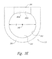
- Figure 3E is a top view of a portion of the coin input tray 110.
- the coin disk 222 is circular and has an upper surface 385 with a generally cone-shaped cross-section defined by a raised center portion 386 and a slightly curved annular surface portion 388. More specifically, in the illustrated embodiment the generally annular surface portion 388 is slightly recessed or concave to give the surface portion 388 a gentle "S" curve.
- this particular contour can facilitate movement of the coins toward the outer periphery of the coin disk 222, especially if the coins are wet, sticky, etc.
- the coin disk 222 can have other cross-sectional shapes.
- the coin disk 222 can have a generally conical shape (e.g., a shallow conical shape) with a raised and/or rounded center portion 386 and a relatively straight annular surface portion extending toward the periphery of the disk 222.
- it is contemplated that the coin disk 222 can have a generally flat cross-sectional shape. Accordingly, the various aspects of the technology described herein are not limited to coin input disks having a particular cross-sectional shape.
- the coin disk bearing 368 can be, e.g., a ball bearing-free slew bearing for noise reduction and to enable the coin disk 222 to carry a relatively high axial load of coins.
- Such bearings include, for example, the PRT 02-30-AL-1 bearing provided by igus® GmbH of Spicher Str. 1 a 51147 Cologne, Germany.
- the bearing 368 can include a rotating center portion 374 to which the second pulley 364 and central shaft 366 are fixedly attached, and an outer flange portion 376 that is fixedly attached to the bottom plate 378 of the coin input tray 110 via, for example, a plurality of suitable fasteners 369 (e.g., bolts, screws, etc.).
- the central shaft 366 extends through the bearing center portion 374 and engages the coin disk 222, enabling the coin disk 222 to rotate freely in either direction when driven by the motor 360 via the drive member 370.
- An outer peripheral portion 323 of the coin disk 222 is slidably supported on an annular support surface or step 353 positioned proximate a lower portion of the coin bowl side wall 352.
- the step 353 can extend in a complete circle around the underside of the coin disk 222. In other embodiments, the step 353 can only extend a portion of the way, or portions of the way, around the coin disk 222.
- a circumferential seal 380 e.g., a felt seal
- the coin input tray 110 can include a header member 390 which forms a portion of the coin bowl 350 and extends over the coin outlet opening 254.
- the header member 390 can include a first side wall portion 392a and a second, recessed side wall portion 392b.
- both the first and second side wall portions 392a, b blend or otherwise smoothly transition into the adjacent portions of the side wall 352 of the coin bowl 350 on opposite ends thereof.
- both side wall portions 392a, b have cylindrical shapes, however, the first side wall portion 392a has a cylindrical shape of larger diameter than the second side wall portion 392b.
- the second side wall portion 392b can have a diameter that is the same as, or is at least complementary to, the diameter D of the coin bowl 350 as defined by the coin bowl side wall portion 352 ( Figure 3A ).
- the coin bowl side wall portion 352 in combination with the second side wall portion 392b of the header member 390 defines a circle centered about the rotational axis 396 of the coin disk 222.
- the first side wall portion 392a of the header member 390 can have a larger diameter than the coin bowl 350, thereby defining a step 394 ( Figure 3D ) in the header member 390 positioned directly above the coin outlet paths 354a, b.
- the inventor has found that providing the step 394 in the header member 390 can facilitate efficient movement of the coins 314 out of the coin input tray 110 via the coin outlet paths 354a, b during operation.
- coins 314 may stand up vertically on edge and be supported by the side wall 352 during rotation of the coin disk 222. Without the step 394, these vertical standing coins 314 can occasionally block coin outlet opening 254 and prevent other coins that may be lying flat from exiting the coin bowl 350 via the coin outlet paths 354a, b.
- the stepped header member 390 in some embodiments, can cause the top of coins 314 that are vertically oriented to tip inwardly toward the center of the coin disk 222 as they pass across the opening 254.
- the weight of the flat-lying coins 314 can then push the bottom portions of the vertically oriented coins 314 outwardly, causing them to tip over and pass through the opening 254 via one of the outlet paths 354a or 354b.
- the inventor has found that absent this step feature 394 vertically oriented coins 314 could potentially pass by the opening 254 and continue around the perimeter of the coin bowl 350 while blocking other flat-lying coins from exiting.
- this feature may be most effective when the coin bowl 350 is full of coins 314 so that the weight of the coin mass holds the vertical coins firmly against the bowl wall. Accordingly, in such embodiments the stepped feature 394 can cause such coins to efficiently move out of the coin bowl 350 via the coin outlet paths 354a, b.
- FIG 4 is an isometric view of the coin input tray 110 with selected structures (e.g., portions of the coin bowl 350) removed to better illustrate the structure and function associated with the coin gate 224.
- the coin gate 224 is fixedly attached to an elongate pivot shaft 494 which has its end portions rotatably supported by journals or other suitable structures (not shown) relative to the coin disk 222.
- the gate 224 can be rectangular shaped and include a relatively flat member 410, e.g., a flat rubber member, which is fixed to the pivot shaft 494 by means of a metal bracket 412, or a similar member, and one or more suitable fasteners.
- the pivot shaft 494 extends longitudinally along a pivot axis A and is configured to rotate thereabout.
- an actuator 490 e.g., a pull-type solenoid
- the actuator 490 can be a pull-type solenoid, such as the 11 HD-C-12D A420-065762-01 solenoid provided by Guardian Industrial Supply, LLC, of 2012 Centimeter Circle Austin, TX 78758.
- the linkage 496 can be pivotably coupled to a first arm 498 that extends from a first end portion of the pivot shaft 494.
- a biasing member 402 (e.g., a coil spring, extension spring, etc.) can be operably coupled to a second arm 404 at an opposite second end portion of the pivot shaft 494 to bias the coin gate 224 toward the closed position (as shown by the depiction of the gate 224 in solid lines in Figure 4 ).
- the input tray controller (described in more detail below) can send one or more signals energizing the actuator 490 and causing the actuator 490 to withdraw the pull rod 492 in direction O. Retracting the pull rod 492 in this manner rotates the first arm 498 downwardly which in turn rotates the coin gate 224 upwardly toward the open position (shown by phantom lines in Figure 4 ).
- the actuator 490 can be a solenoid that requires, e.g., a 24VDC kicker pulse that lasts for, e.g., 500 milliseconds, and then requires a continuous 12VDC holding voltage to hold the gate 224 in the open position.
- the biasing member 402 can apply a tension force to the second arm 404 which urges the gate 224 toward the closed position.
- the coin input tray 110 can include a sensor 408, such as an infrared position sensor (or other type of sensor) to detect the position of the gate 224.
- the second arm 404 can serve as a position flag that moves into position adjacent the sensor 408 and is detected by the sensor 408 when the gate 224 rotates to the open position.
- the controller can send a signal or otherwise de-energize the actuator 490, causing the pull rod 492 to return upwardly in direction C, thereby rotating the gate 224 downwardly to the closed position, assisted by the biasing member 402.
- FIG. 5 is a schematic diagram of a system 500 for controlling operation of the coin input tray 110 and related apparatuses and systems described in detail above, in accordance with an embodiment of the present technology.
- the controller 502 can be embodied in a special purpose computer or data processor that is specifically programmed, configured, or otherwise constructed to perform one or more of the computer-executable instructions or routines described herein.
- the controller 502 can include, e.g., a programmable logic controller (PLC), a printed circuit board (PCD) carrying various processing and/or memory devices, etc.
- PLC programmable logic controller
- PCD printed circuit board
- the controller 502 can include computer-readable storage media that contain computer-executable instructions for causing the various subsystems of the apparatuses and systems described herein to perform the operations and methods described herein. While aspects of the present technology, such as certain functions associated with the coin input tray 110, may be described as being performed exclusively on a single device, the technology can also be practiced in distributed environments where functions or modules are shared among disparate processing devices, which may or may not be linked.
- the various routines and functions described herein may be stored or distributed on tangible computer-readable media, including magnetically or optically readable computer discs, hard-wired or preprogrammed chips (e.g., EEPROM semiconductor chips, etc.), nanotechnology memory, and/or other data storage media. Alternatively, computer implemented instructions, data structures, and other data associated with aspects of the present technology may be distributed over a network.
- the controller 502 can receive a start signal from the start button 132a, b described above and shown in, e.g., Figure 1A .
- the controller 502 can receive a start signal from an auto-start sensor 532.
- the auto-start sensor 532 can include a vibration sensor, an infrared sensor, an electromagnetic sensor, and/or other type of sensor that automatically starts operation of the coin disk 222 and/or other operations of the kiosk 100 (e.g., the coin cleaner 230 and/or the coin processing apparatus 120).
- the system 500 can include a digital clock or timer 506 operably providing input to the controller 502 during operation of the various kiosk systems.
- the controller 502 can control power provided to one or more of the gate actuator 490, the coin disk motor 360, a coin cleaner motor 512, and/or a coin processing apparatus motor 514 by a power source 504 (e.g., an electric power source, such as facility power, on-board kiosk power (provided by, e.g., a battery or transformer), etc.).
- a gate sensor 508 e.g., an infrared position sensor
- the motor encoder 310 (e.g., an incremental rotary encoder, such as the E4P-200-236-N-S-D-M-B encoder provided by US Digital of 1400 NE 136th Avenue Vancouver, Washington 98684), can be operably coupled to the disk motor 360. More specifically, as known to those of ordinary skill in the art, the encoder 310 can provide an electrical signal that can be used to monitor and/or control the speed, position, and/or direction of the output shaft of the disk motor 360. The encoder 310 alone and/or in conjunction with the controller 502 can be used to then make adjustments to the speed, position, and/or direction of the motor shaft if necessary to provide or maintain desired movement of the coin disk 222 as described above.
- the coin cleaner motor 512 and/or the coin processing apparatus motor 514 can include similar encoders to provide various operating parameters to the controller 502 during operation of the associated systems.
- the user can depress the start button 132a, b to begin a coin intake process using the coin input tray 110.
- the coin input tray can start automatically in response to a signal from the auto-start sensor 532).
- the controller 502 can respond to the signal by providing power from the power source 504 to the disk motor 360, the gate actuator 490, the cleaner motor 512 and/or the coin processing apparatus motor 514.
- the gate actuator can open the gate 224 (see e.g., Figure 4 ) and the motor 360 can begin rotation of the coin disk 222.
- the encoder 310 can send direction, velocity, and/or position information to the controller 502.
- the controller 502 can respond to the information by stopping the disk motor 360 after a preset period of time (or a preset number of rotations) and/or by pausing the motor momentarily, before starting rotation of the coin disk 222 in the opposite direction.
- the cleaner motor 512 rotates the coin cleaner 230 and provides clean coins to the coin processing apparatus 120 for discrimination and counting and/or sorting.
- the controller 502 can reverse the voltage from the power source 504 to cause the motor 360 to rotate in the opposite direction in an attempt to clear or unjam the coin disk 222.
- the controller 502 can also reverse the direction of coin disk 222 if, for example, the activity sensor(s) 382/383 indicate that there is a coin jam proximate the coin outlet opening 254 ( Figure 3A ).
- the controller 502 can cut power to the disk motor 360 and simultaneously cause the gate actuator 490 to close the coin gate 224 so that no further coins are transferred to the coin cleaner 230 until the jam or other issue is resolved.
- the controller 502 senses that the coin cleaner motor 512 is drawing too much current, indicating that the coin cleaner 230 could be jammed or otherwise immobilized, the controller 502 can cut power to the disk motor 360 and simultaneously cause the gate actuator 490 to close the coin gate 224 so that no further coins are transferred to the coin cleaner 230 until the jam or other malfunction of the coin cleaner is cleared.
- the jam in the coin cleaner may be cleared or otherwise resolved by reversing the voltage provided from the power source 504 to the coin cleaner motor 512, thereby causing the coin cleaner 230 to rotate in a counter direction to dislodge the jammed coins or other matter.
- the controller 502 senses that the coin processing apparatus motor 514 is drawing too much current or is otherwise experiencing a jam in the coin processing apparatus 120, the controller 502 can send similar signals to the gate actuator 490, the disk motor 360, and/or the coin cleaner motor 512 causing them to stop operation until the jam or other malfunction of the coin processing apparatus 120 is resolved.
- system 500 described above as well as the corresponding functions are provided by way of non-limiting example of one system architecture and/or functions for controlling operation of the coin input tray 110 and associated apparatuses and systems described above. Accordingly, in other embodiments, other power, control, signal, data, and/or other systems can be used to control these apparatuses without departing from the spirit or scope of the present technology.
- Figures 6A-C are representative flow diagrams illustrating routines 600a-600c for operating the coin input tray 110 and associated systems in accordance with embodiments of the present technology.
- the routines 600a-c or portions thereof can be performed by the controller 502 ( Figure 5 ) in accordance with computer-executable instructions.
- the routines 600a-c or portions thereof can be performed by other data processing devices associated with the kiosk 100.
- the routines 600a-600c do not necessarily show all functions or exchanges of data, but instead provide an understanding of various steps, commands, and/or data exchanges that can be utilized in accordance with the present technology.
- routines 600a-600c can be combined with portions from other of the routines 600a-600c to create other useful routines for operating the coin input tray 110.
- steps depicted in the routines 600a-600c can itself include a sequence of operations that need not be described herein.
- processes or blocks are presented in a given order, alternative implementations may perform routines having steps, or employ systems having blocks, in a different order, and some processes or blocks may be deleted, moved, added, subdivided, combined, and/or modified to provide alternative or sub-combinations. Each of these processes or blocks may be implemented in a variety of different ways. Also, while processes or blocks are at times shown as being performed in series, these processes or blocks may instead be performed or implemented in parallel, or may be performed at different times.
- the routine 600a begins when a user pours or otherwise deposits a batch of coins into the coin input tray 110.
- the routine receives a start signal (e.g., by the user depressing a start button).
- the routine sets a time equal to T 0
- the routine opens the coin gate 224.
- the coin disk 222 begins rotating in a first direction and at a speed (e.g., a preset speed, such as 45 RPM).
- the routine determines if the coin disk 222 has been rotating in the first direction for an elapsed time equal to T.
- the elapsed time T can be equal to a period of time between 0.5 second and 3 seconds, such as 2 seconds.
- the coin disk 222 can be configured to rotate in one direction for other periods of time (and/or for selected or preset numbers of revolutions). If the coin disk 222 has not rotated for the period T, the coin disk 222 continues rotating in the first direction. Conversely, if the elapsed time is equal to T, then the coin disk 222 stops as noted in block 610a. In some embodiments, the coin disk can pause in the stop position for a preset period of time, such as a time period from about zero seconds to about 2 seconds, or about 1 second.
- the routine determines if all of the coins that were put into the tray by the user have been transferred out of the tray through the exit opening. If so, the routine closes the gate 224 in block 618a and then ends. If not, the routine proceeds to block 614a and resets the time equal to T 0 . In block 616a, the routine then begins rotating the coin disk 222 in the opposite direction, and continues to decision block 608a and proceeds as described above. In the foregoing manner, the coin disk 222 can alternately rotate in opposite directions until all of the coins have been transferred out of the coin input tray 110.
- the flow routine 600b describes a process for operating the coin input tray 110 and related systems in accordance with another embodiment of the present technology.
- the routine begins when the coins are poured into the coin input tray 110 and a start signal is received in block 602b.
- the time is set to T 0 .
- the coin gate 224 is opened, and in block 606b, the coin disk 222 begins rotating in a first direction.
- the routine determines if there is a jam (e.g., a coin jam) somewhere in the system. For example, a coin jam could be detected at the coin outlet opening 254 of the coin input tray 110, at the coin cleaner 230, and/or at the coin processing apparatus 120.
- a jam e.g., a coin jam
- the routine proceeds to block 611 b and stops rotation of the coin disk 222. Additionally, in some embodiments the coin disk 222 can be paused in the stopped position for a preset period of time. After stopping (and/or pausing), the routine proceeds to block 614b and resets the time to T 0 . Then, in block 616b, the coin disk 222 starts rotating in the opposite direction. From block 616b, the routine returns to decision block 607b to determine if the counter rotation of the coin disk has alleviated the jam. If not, the routine proceeds again to block 611 b and repeats as described above to alleviate the jam.
- the routine proceeds to decision block 608b to determine if the coin disk 222 has been rotating in one direction for an elapsed time equal to T.
- the elapsed time T can be equal to a period of time between 0.5 second and 3 seconds, such as about 2 seconds.
- the coin disk 222 can be configured to rotate in one direction for other periods of time. If the coin disk has not been rotating in the particular direction for a period of time equal to T, then the routine returns to decision block 607b and proceeds as described above. Once the coin disk has rotated in the direction for the preset period of time T, the routine proceeds to block 610b and stops (and/or pauses) the coin disk 222.
- the routine proceeds to decision block 612b to determine if all the coins that were deposited in the coin input tray 110 have been transferred out of the coin input tray 110 through the coin outlet opening 254. If not, the routine returns to block 614b and resets the time to T 0 . From block 614b, the routine proceeds to block 616b and begins rotating the coin disk in the opposite direction as described above. Once all of the coins have been transferred out of the coin input tray 110, the routine ends.
- the routine 600c describes yet another process for operating the coin input tray 110 and associated systems in accordance with an embodiment of the present technology.
- the routine 600c begins when coins are dumped or otherwise placed into the coin input tray 110 and a start signal is received (block 602c).
- the routine sets the time equal to T 0 .
- the routine then opens the coin gate 224 in block 605c, and starts rotating the coin disk 222 in a first direction in block 606c. As the coin disk 222 rotates, it transfers coins placed thereon out of the coin input tray 110 through the coin outlet opening 254 and past the open coin gate 224.
- the routine determines if an amount of time equal to T has elapsed. If not, the routine continues to rotate the coin disk 222 until a period of time equal to T has elapsed. Once a time period equal to T has elapsed, the routine proceeds to block 610c to pause the coin disk for a preset period of time equal to P.
- the period of time P can be equal to a period of time between zero seconds and 3 seconds, such as about 1 second. In other embodiments, the coin disk 222 can be paused for other periods of time P.
- the routine proceeds to decision block 611c to determine if the coin disk should be paused for a longer period of time. For example, in some embodiments the routine can determine (via, e.g. a sensor operably positioned relative to the coin cleaner 230) if the coin cleaner 230 is currently operating at full capacity (e.g., the coin cleaner 230 cannot receive any more coins until it has processed at least a portion of the coins it currently contains), and/or if the coin processing apparatus 120 is operating capacity. If either the coin cleaner 230 or the coin processing apparatus 120 is currently operating at capacity and should not receive additional coins at the moment, the routine returns to block 610c to extend the period of pausing the coin disk 222.
- the routine can determine (via, e.g. a sensor operably positioned relative to the coin cleaner 230) if the coin cleaner 230 is currently operating at full capacity (e.g., the coin cleaner 230 cannot receive any more coins until it has processed at least a portion of the coins it currently contains), and/or if the coin processing apparatus
- the routine proceeds to decision block 612c to determine if all of the coins have been transferred out of the tray. If not, the routine proceeds to block 614c and resets the timer to T 0 . The routine then proceeds to block 616c and starts rotating the coin disk 222 in the opposite direction, and from there the routine returns to decision block 608c and proceeds as described above. Returning to decision block 612c, once all the coins have been transferred out of the coin input tray 110, the routine proceeds to 618c and closes the coin gate 224, after which the routine ends.
- routines 600a-600c can be stored in memory (e.g., nonvolatile memory) that forms a portion of the controller 502 ( Figure 5 ) or can be stored in removable media, such as discs, or hardwired or preprogrammed in chips such as EEPROM semiconductor chips.
- memory e.g., nonvolatile memory
- removable media such as discs, or hardwired or preprogrammed in chips such as EEPROM semiconductor chips.
- ASIC application specific integrated circuit
- DSP digital signal processing
- ASIC application specific integrated circuit
- DSP digital signal processing
- Such software can be stored on any suitable computer-readable medium, such as microcode stored in a semiconductor chip, on a computer-readable disc, or downloaded from a server and stored locally at a client. Accordingly, although specific circuitry may be described herein, those of ordinary skill in the art will recognize that a microprocessor-based system could also be used for any logical decisions that are configured in software.
- aspects of the routines described herein can be embodied in a special purpose computer or data processor (e.g., the controller 502) that is specifically programmed, configured, or constructed to perform one or more of the computer-executable instructions explained in detail herein. While aspects of the invention, such as certain functions, are described as being performed exclusively on a single device, the invention can also be practiced in distributed environments where functions or modules are shared among disparate processing devices, which are linked through a communications network, such as a Local Area Network (LAN), Wide Area Network (WAN), or the Internet. In a distributed computing environment, program modules may be located in both local and remote memory storage devices.
- LAN Local Area Network
- WAN Wide Area Network
- Internet the Internet
- aspects of the invention may be stored or distributed on tangible computer-readable media, including magnetically or optically readable computer discs, hard-wired or preprogrammed chips (e.g., EEPROM semiconductor chips), nanotechnology memory, biological memory, or other data storage media.
- computer implemented instructions, data structures, screen displays, and other data under aspects of the invention may be distributed over the Internet or over other networks (including wireless networks), on a propagated signal on a propagation medium (e.g., an electromagnetic wave(s), a sound wave, etc.) over a period of time, or they may be provided on any analog or digital network (packet switched, circuit switched, or other scheme).
- display descriptions may be in HTML, XML or WAP format, email format or any other format suitable for displaying information (including character/code-based formats, algorithm-based formats (e.g., vector generated), and bitmapped formats).
- various communication channels such as local area networks, wide area networks, or point-to-point dial-up connections, may be used instead of the Internet.
- the system may be conducted within a single computer environment, rather than a client/server environment.
- the user computers may comprise any combination of hardware or software that interacts with the server computer, such as television-based systems and various other consumer products through which commercial or noncommercial transactions can be conducted.
- the various aspects of the invention described herein can be implemented in or for any e-mail environment.
- the words “comprise,” “comprising,” and the like are to be construed in an inclusive sense, as opposed to an exclusive or exhaustive sense; that is to say, in the sense of "including, but not limited to.”
- the terms “connected,” “coupled,” or any variant thereof means any connection or coupling, either direct or indirect, between two or more elements; the coupling or connection between the elements can be physical, logical, or a combination thereof.
- the words “herein,” “above,” “below,” and words of similar import, when used in this application refer to this application as a whole and not to any particular portions of this application.
Abstract
Description
- The following disclosure relates generally to coin processing machines and, more particularly, to coin input apparatuses and methods for use with coin counting and/or sorting machines, such as consumer-operated coin counting machines and the like.
- Various types of coin counting machines are known. Some coin counting machines (e.g., vending machines, gaming devices such as slot machines, and the like) are configured to receive one coin at a time through a slot. These machines are relatively simple and typically designed for relatively low throughput and little, if any, coin cleaning. Such machines, however, are usually ill-suited for counting large quantities of consumer coins received all at once (such as a large quantity of coins poured into a machine from, e.g., a coin jar).
- Machines for counting and/or sorting relatively large quantities of consumer coins include those disclosed in, for example,
U.S. Patent Nos. 5,620,079 ,7,028,827 ,7,520,374 , and7,865,432 , each of which is incorporated herein by reference in its entirety. Some of these machines count consumer coins and dispense redeemable cash vouchers, while others may offer other types of products and services either exclusively or in addition to vouchers. Such products and services can include, for example, dispensing and/or topping-up prepaid cards (e.g., gift cards, phone cards, etc.), "e-certificates," and the like, and transfers to online accounts (e.g., Paypal™), mobile wallets, etc. Vouchers can be redeemed for cash and/or merchandise at a point of sale (POS) in a retail establishment, while e-certificates can enable the holder to purchase items online by inputting a code from the e-certificate when making the purchase. Prepaid gift cards can be used to make POS purchases by, for example, swiping the card through a conventional card reader, and prepaid phone cards can be used for making cell phone calls. The term "mobile wallet" can refer generally to an electronic commerce account implemented by a mobile phone or other mobile wireless device. In some embodiments, mobile wallets store "virtual gift cards," virtual loyalty cards, etc.; transfer value; and/or conduct transactions for, e.g., purchasing goods and/or services from suitably enabled merchants. The term "virtual gift card" can refer to an application program operating on the mobile device that performs like a prepaid card, such as a gift card. Virtual gift cards can enable the user to wirelessly purchase items and/or services, pay bills, and/or conduct other transactions with retailers and other merchants via, e.g., a wirelessly enabled point of sale (POS) terminal, the Internet, and/or other computer networks. - Some coin counting and/or sorting machines include a hinged coin input tray that is manually lifted by the user to introduce their coins into the machine for processing. Such an input tray is disclosed in, for example,
U.S. Pat. No. 5,620,079 . When at rest, the input tray is angled downward and away from a raised hinge line that forms a slight peak. This prevents coins in the tray from flowing into the machine until the user begins rotating the tray upwardly about the peak. As the user continues lifting the input tray, the coins begin to slide out of the tray, over the peak and into the machine for counting and/or sorting. In some instances, the user may be required to use their hands to manually control the flow of coins out of the input tray. For example, if the user lifts the tray too fast, the user may need to place their hands near the peak to prevent coins from leaving the input tray too quickly and jamming the machine. On the other hand, if the user lifts the tray too slowly, the user may need to move some coins out of the tray and over the peak by hand. In either case, user involvement may be necessary to facilitate the coin input process.U.S. Pat. No. 6,602,125 , which is incorporated herein by reference in its entirety, disclosed an automatic coin input tray for a self-service coin-counting machine. The input tray employed a spring-loaded rotating disk that would drop if the user poured in more coins than the tray could initially process. This dropping feature can make it difficult to adequately seal gaps between the rotating disk and the surrounding coin bowl. - Speed and accuracy are important considerations in self-service coin counting machines. Consumers are less inclined to use a coin counting machine if they have to wait an appreciable amount of time to have their coins counted. Coin counting machines should also be accurate and relatively easy to operate to encourage use. Accordingly, it would be advantageous to provide coin counting machines with coin input systems that are relatively easy to use, and facilitate accurate and relatively fast counting of large quantities of coins.
-
-
Figures 1A-1C are a series of front isometric views of a coin counting kiosk having a coin input apparatus configured in accordance with an embodiment of the present technology. -
Figure 2A is an enlarged front isometric view of a portion of the coin counting kiosk ofFigure 1A illustrating a coin input apparatus configured in accordance with an embodiment of the present technology, andFigures 2B and2C are further enlarged front and rear isometric views, respectively, of the coin input apparatus and an associated coin counting and/or sorting apparatus. -
Figures 3A and3B are enlarged top and bottom isometric views, respectively, of the coin input apparatus ofFigures 2A-2C ;Figure 3C is a cross-sectional isometric view,Figure 3D is an enlarged cross-sectional side view, andFigure 3E is a top view of the coin input apparatus configured in accordance with embodiments of the present technology. -
Figure 4 is an enlarged top isometric view of the coin input apparatus ofFigures 2A-3D , with selected surrounding structures removed for purposes of illustration. -
Figure 5 is a block diagram of a suitable system for operating a coin input apparatus configured in accordance with the present technology. -
Figures 6A-6C are a series of flow diagrams illustrating routines for operating a coin input apparatus configured in accordance with embodiments of the present technology. - The following disclosure describes various embodiments of apparatuses, systems and methods for receiving a plurality of coins and transferring the coins into a kiosk or machine for, e.g., counting, sorting and/or other processing of the coins. In some embodiments, for example, a coin input tray configured in accordance with the present technology can include a rotating disk disposed in a bowl structure for transferring coins placed thereon into a consumer-operated coin-counting kiosk or similar machine for counting therein. In operation, the coin disk can automatically change direction of rotation to quickly and efficiently transfer the coins into the consumer-operated kiosk without requiring the user to manually move the coins into the kiosk for counting and/or other processing. As described in greater detail below, in some embodiments the rotating coin disk can drive the coins out of the coin input tray along two different paths depending on the direction of disk rotation, and this feature can reduce the tendency of coins to jam or otherwise clog the outlet opening of the coin input tray.
- The various embodiments of coin input apparatuses described herein can be used with various types of self-service and/or consumer-operated coin counting machines configured to receive large batches of random coins from users in exchange for, e.g., redeemable cash vouchers, prepaid cards (e.g., gift cards), e-certificates, etc., and/or deposits in on-line accounts, mobile wallets, etc. Certain details are set forth in the following description and in
Figures 1A-6C to provide a thorough understanding of various embodiments of the present technology. In some instances well-known structures, materials, operations, and/or systems often associated with coin counting machines and associated systems and methods are not shown or described in detail herein to avoid unnecessarily obscuring the description of the various embodiments of the technology. Those of ordinary skill in the art will recognize, however, that the present technology can be practiced without one or more of the details set forth herein, or with other structures, methods, components, and so forth. - The accompanying Figures depict embodiments of the present technology and are not intended to be limiting of its scope. The sizes of various depicted elements are not necessarily drawn to scale, and these various elements may be arbitrarily enlarged to improve legibility. Component details may be abstracted in the Figures to exclude details such as position of components and certain precise connections between such components when such details are unnecessary for a complete understanding of how to make and use the invention.
- Many of the details, dimensions, angles and other features shown in the Figures are merely illustrative of particular embodiments of the disclosure. Accordingly, other embodiments can have other details, dimensions, angles and features without departing from the spirit or scope of the present invention. In addition, those of ordinary skill in the art will appreciate that further embodiments of the invention can be practiced without several of the details described below.
- In the Figures, identical reference numbers identify identical, or at least generally similar, elements. To facilitate the discussion of any particular element, the most significant digit or digits of any reference number refers to the Figure in which that element is first introduced. For example,
element 110 is first introduced and discussed with reference toFigure 1A . -
Figure 1A is a partially schematic front isometric view of a consumer-operatedkiosk 100 having a coin input apparatus configured in accordance with an embodiment of the present technology. In the illustrated embodiment, the coin input apparatus includes acoin input tray 110 that is accessibly positioned on a "bump-out" 118 of a countertop ordeck 116 of thekiosk 100. By way of example, thekiosk 100 can be a consumer-operated coin counting machine that can include, for example, the ability to count consumer coins poured into thecoin input tray 110 and dispense redeemable vouchers (e.g., cash vouchers), dispense and/or reload prepaid cards, dispense e-certificates for on-line purchases, transfer funds to remote accounts (e.g., on-line payment accounts, etc.), and/or provide other products and services in exchange for the coins. Thekiosk 100 and associated systems, and various embodiments thereof, can be at least generally similar in structure and function to one or more of the kiosks and associated systems and methods disclosed in:U.S. Patent Nos. 8,482,413 ,7,865,432 ,7,815,071 ,7,653,599 ,7,520,374 ,7,014,108 ,6,494,776 ,6,168,001 ,6,047,808 ,5,988,348 ,5,842,916 ,5,799,767 and5,620,079 ; andU.S. Patent Application Nos. 13/802,070 ,13/790,674 13/728,905 13/367,129 13/304,254 13/286,971 - In the illustrated embodiment, the
kiosk 100 includes a display screen 112 (e.g., a video screen) that can display various user-selection graphics or buttons (via, e.g., a touch screen) that enables the user to make selections and provide operating instructions to thekiosk 100 in response to prompts displayed on thedisplay screen 112. Thekiosk 100 can additionally include aspeaker 115 for audibly providing prompts, instructions, advertisements, etc. to users. Thekiosk 100 can also include avoucher outlet 114 that can dispense, e.g., a redeemable voucher, e-certificate, etc. for all or a portion of the value of the coins deposited in thecoin input tray 110. In some embodiments, thekiosk 100 can also include acard outlet 122 from which the user can receive, e.g., a new prepaid card (e.g., a prepaid gift card, phone card, credit card, etc.), an e-certificate, etc. for all or a portion of the coin value, acard reader 124 with which the user can swipe an existing prepaid card and reload or "top-up" the card or an associated account with all or a portion of the coin value, and/or abill accepter 126 for receiving paper currency from the user in payment for a product or service. In some embodiments, thekiosk 100 can include additional user-interface devices, such as a user-interface panel 130 accessibly positioned below thedeck 116 and having various user input devices including, for example, a keypad, a card reader, a bill acceptor, etc. Thekiosk 100 can additionally include a communications facility 106 (e.g., a router, modem, etc.; shown schematically) for remotely exchanging information with various user computers, servers, financial institutions, and/or other remote computer systems and providing the various kiosk products and services described herein. Thekiosk 100 can operate in a network environment using logical connections to one or more remote computers over various suitable communications links, including the Internet. Such remote computers can include, for example, personal computers, servers, routers, network PCs, network nodes, etc. In network environments, program modules, application programs, and/or data, or portions thereof, can be stored in remote computers and accessed by or sent to thekiosk 100, and/or sent from thekiosk 100 to one or more remote computers. Thecommunications facility 106 and/or the associated network connections discussed above are only some examples of suitable communication links between thekiosk 100 and other remote computers and associated devices. In other embodiments, other types of communication facilities and links, including wireless links, can be used. Such networking environments are well known, and can include links comprising Local Area Networks (LAN), Wide Area Networks (WAN), or the Internet. In such distributed computing environments, program modules may be located in both local and remote memory storage devices. - The
kiosk 100 described above is merely representative of one type of consumer-operated or self-service kiosk, commercial enclosure, or other type of coin processing machine that can utilize the coin input apparatuses, systems and methods described herein. Accordingly, in other embodiments, other types of consumer-operated kiosks, machines, etc. can utilize the technology described herein. Such kiosks can include, for example, DVD rental kiosks, food vending machines such as coffee vending machines, card dispensing machines, gift card dispensing and exchange machines, etc. Moreover, in other embodiments other kiosks and machines utilizing the coin input apparatuses, systems and methods described herein can include more, fewer, or different functionalities than those described herein. - In operation, the user wishing to have, for example, a batch of coins of random denomination counted by the kiosk 100 (in return for, e.g., a redeemable voucher, e-certificate, gift card value, transfer to online account, transfer to mobile wallet, etc.) can approach the
kiosk 100 and pour the coins into thecoin input tray 110. As described in greater detail below, thecoin input tray 110 can include a rotating coin disk forming a bottom-portion thereof. In some embodiments, the user can press a start button to begin rotation of the coin disk for transferring the coins into thekiosk 100 for counting. The start button can be, e.g., graphically represented on thedisplay screen 112 by astart button icon 132a or similar feature. In other embodiments, thekiosk 100 can include anphysical start button 132b positioned proximate thecoin input 110 which the user can depress to start the coin input process. In still further embodiments, thekiosk 100 can include a coin detection sensor that automatically starts rotation of the coin disk (and/or other coin processing components and systems) in response to detecting, for example, the presence of coins placed on the coin disk. As described in greater detail below, in some embodiments the coin disk can rotate in a first direction for a preset (or user-controlled) period of time (or number of rotations), and then stop (and/or pause) and rotate in the opposite direction for a preset (or user-controlled) period of time. This back and forth process can continue until all the coins have been transferred from thecoin input tray 110 to a coin counting and/or sorting apparatus 120 (shown schematically inFigure 1A ) housed within thekiosk 100. The coin counting and/or sortingapparatus 120 can count the coins to determine a value which the user can apply to their selected product and/or service. In the illustrated embodiment, thekiosk 100 can also include acoin return outlet 104 for returning coins to the user that were not counted, including fraudulent coins, damaged coins, and/or if the user wishes to decline the coin counting operation. - In some embodiments, a coin input tray cover (not shown), such as a clear plastic cover, can be hingedly or otherwise attached to the
kiosk deck 116 proximate thecoin input tray 110. The user can open the cover to pour their coins into thecoin input tray 110, and then close the cover before pressing thestart button 132a, b to begin the coin intake process. In other embodiments, the coin disk can begin rotating automatically in response to a signal generated by the cover being closed. In some embodiments, the use of a cover can reduce the ambient noise from operation of thecoin input tray 110. - In the illustrated embodiment, the
kiosk 100 includes an external housing, such as anenclosure 102, having a hinged access panel, such as adoor 108 that permits access to the interior portion of theenclosure 102. Thedoor 108 is rotatably mounted proximate a corner portion of theenclosure 102 by avertical hinge 103. Thehinge 103 allows thedoor 108 to rotate between a closed position as shown inFigure 1A , and an open position as shown inFigures 1B and1C . - Referring to
Figure 1B , thedoor 108 can be unlocked and rotated in direction R to an open position for, e.g., servicing of the coin counting and/or sortingapparatus 120. As this view illustrates, in the illustrated embodiment thecoin input tray 110 and thedeck 116 are fixedly mounted to thedoor 108. Moreover, in this embodiment thecoin input tray 110 is driven in operation by adrive system 140 that is positioned beneath thedeck 116 and carried by thedoor 108. As described in greater detail below, thecoin input tray 110 includes a coin outlet opening or passageway that directs coins from thecoin input tray 110 into anadjacent funnel 136 for conveyance to the coin counting and/or sortingapparatus 120. In one aspect of the illustrated embodiment, the coin outlet opening of thecoin input tray 110 can passively disengage or otherwise move away from thefunnel 136 when thedoor 108 is rotated to the open position. This arrangement enables thecoin input tray 110 and the associateddrive system 140 to be easily serviced after thedoor 108 has been opened. As described in greater detail below with reference toFigure 1C , this arrangement can also facilitate servicing of the coin counting and/or sortingapparatus 120. - In the illustrated embodiment, the coin counting and/or sorting
apparatus 120 can be at least generally similar in structure and function to the coin counting and/or sorting apparatuses disclosed inU.S. Patent App. No. 13/906,126, filed May 30, 2013 apparatus 120 is configured and/or used as a coin counting apparatus, but in other embodiments theapparatus 100 can be suitably configured and/or used as a coin sorter, or as a coin counter and sorter. Accordingly, for ease of reference theapparatus 120 is referred to herein as a coin "processing" apparatus, with the understanding that theapparatus 120 and various features and structures thereof can be used in various embodiments for coin counting, coin sorting, or for coin counting and sorting. In other embodiments, thekiosk 100 and/or other kiosks and machines utilizing the coin input technology and related technologies described herein can include other types of coin counting and/or sorting apparatuses, systems, and/or methods, such as those disclosed inU.S. Patent App. No. 13/778,461, filed February 27, 2013 - In some embodiments as illustrated in
Figure 1C , thecoin processing apparatus 120 can be moved forward from its operating position on extendable rails 134 (identified individually as a first rail 134a and asecond rail 134b). For example, in the illustrated embodiment a service person can pull on thecoin processing apparatus 120 to extend the rails 134 outwardly in direction S with thecoin processing apparatus 120 supported thereon. Once thecoin processing apparatus 120 is positioned generally clear of the surrounding kiosk structure, astructure 138 that supports a coin cleaner (e.g., thecoin cleaner 230 described below with reference toFigures 2A-2C ) can be rotated downwardly in the direction of arrow D, and thecoin processing apparatus 120 can be rotated upwardly and forward in the direction of arrow P to afford the service person access to various components and systems associated with thecoin processing apparatus 120. Once any necessary servicing has been completed, thecoin processing apparatus 120 can be rotated downwardly in the direction of the arrow P, thestructure 138 can be rotated upwardly in the direction of the arrow D, and thecoin processing apparatus 120 can be pushed back into thekiosk 100 on the rails 134 in direction S. Thedoor 108 can then be rotated to the closed position shown inFigure 1A and thekiosk 100 put back into service. -
Figure 2A is an enlarged front isometric view of a portion of thekiosk 100 with selected outer panels and other structures (e.g., the drive system 140) removed for purposes of better illustrating the operational relationship between thecoin input tray 110 and thecoin processing apparatus 120, in accordance with an embodiment of the present technology.Figure 2B is a further enlarged front isometric view, andFigure 2C is a rear isometric view, of thecoin input tray 110 and thecoin processing apparatus 120. Referring toFigures 2A-2C together, thecoin input tray 110 includes arotatable coin disk 222 adjacent to acoin outlet opening 254. As shown inFigure 2C , amovable gate 224 can obstruct or cover thecoin outlet opening 254 when thecoin input tray 110 is not in use, and then move (e.g., rotate) away from the opening to clear the coin path for use. As described in greater detail below, in operation thecoin disk 222 rotates (e.g., in alternating directions) to move the coins out of thecoin input tray 110 and into thefunnel 136 though theopening 254. Thefunnel 136 has downwardly sloping bottom surfaces that direct the coins into afeed hopper 228 having an inlet positioned directly beneath an outlet of thefunnel 136. Thefeed hopper 228 of the illustrated embodiment also includes downwardly sloping bottom surfaces that direct the coins received therein into acoin cleaner 230 through afirst opening 238. - In the illustrated embodiment, the
coin cleaner 230 can be a rotating drum-type coin cleaner having a plurality of openings in an exterior wall thereof. The openings enable dirt, debris and other unwanted material that may be mixed with the coins to fall out of the rotating drum, thereby cleaning the coins as the coins tumble through the rotating drum. Such coin cleaners can be at least generally similar in structure and function to coin cleaners disclosed inU.S. Patent No. 6,174,230 , which is incorporated herein by reference in its entirety. As thecoin cleaner 230 rotates about its longitudinal axis, the rotational movement drives the coins therein from thefirst opening 238 toward asecond opening 240. In the illustrated embodiment, the rotational movement drives the coins out of thecoin cleaner 230 and onto aramp 232, which directs the clean coins into acoin hopper 236 of thecoin processing apparatus 120 via aninlet 234. As noted above, thecoin processing apparatus 120 can discriminate and count, sort, or count and sort the coins in the manner described inU.S. Patent App. No. 13/906,126 , which is incorporated herein in its entirety by reference. For example, coins that are properly discriminated and counted can be transferred to one or more removable coin bins 248a, b via first and secondcoin acceptance chutes 244a, b (Figure 2B ) which are connected tocorresponding coin tubes 246a, b (Figure 2C ). Unwanted coins, or coins that cannot be properly discriminated can be transferred to the coin outlet 104 (Figure 1A ) via a suitablecoin return chute 242 for collection by the user. Alternatively, if the user elects not to have their coins counted in return for, e.g., a redeemable voucher or other item, the user can decline the service and have all of their coins returned via thecoin return outlet 104. -
Figure 3A is an enlarged top isometric view, andFigure 3B is a corresponding bottom isometric view, of thecoin input tray 110 configured in accordance with an embodiment of the present technology. Referring first toFigure 3A , in the illustrated embodiment thecoin disk 222 forms a bottom portion of a coin receptacle orbowl 350. Thecoin bowl 350 includes a side wall 352 (e.g., a vertical side wall). In the illustrated embodiment, theside wall 352 includes acylindrically wall portion 351 that extends around a portion of thecoin disk 222 proximate an outer edge or periphery of thecoin disk 222. In some embodiments, theside wall 352 can have a height H of from about .5 inch to about 2 inches or more, or about .75 inch; and thecoin disk 222 can have a diameter D of from about 3 inches to about 12 inches or more, or about 6 inches. Each end of thecylindrical wall portion 351 transitions into a corresponding angled wall portion 357 (identified as a first angled wall portion 357a and a secondangled wall portion 357b) which extends inwardly toward opposite sides of thecoin outlet opening 254. In the illustrated embodiment, the size of the coin outlet opening 254 can be selected to produce favorable coin flow out of thecoin input tray 110 while at the same time blocking larger pieces of non-coin items, debris, etc. from passing through the opening and on to, for example,coin cleaner 230. For example, in some embodiments, the coin outlet opening 254 can have a width W from aleft boundary 398a to aright boundary 398b of from about 1 inch to about 6 inches or more, or about 3 inches. As shown inFigure 3D , the coin outlet opening 254 can also have a height Y from alower boundary 399a to an upper boundary 399b of from about .25 inch to about 1 inch or more, or about .5 inch. In other embodiments, the coin outlet opening can have other width and/or height dimensions. In other embodiments, coin input trays configured in accordance with the present technology can have other diameters, heights, bowl dimensions, shapes, etc. without departing from the present disclosure. - In the illustrated embodiment, the
coin disk 222 further includes a plurality of recesses orpockets 355 formed in the outer surface thereof. Thepockets 355 extend radially outward from the center of thecoin disk 222 toward the periphery of thecoin disk 222, and can be symmetrically distributed around thecoin disk 222. For example, the illustrated embodiment includes eightcoin pockets 355 evenly spaced apart by equal angles of 45 degrees. Each of thepockets 355 can have a bottom surface portion 356 (e.g., a generally horizontal bottom surface portion) that extends at least generally parallel to the plane of rotation of thecoin disk 222. Thebottom surface portions 356 can also be generally coplanar with the outer periphery of thecoin disk 222. The inventor has found that, in certain embodiments, the coin pockets 355 favorably agitate and move the coins out of thecoin input tray 110 through theopening 254 during operation. In other embodiments, however, thecoin disk 222 can have recesses or pockets with other shapes, and/or thecoin disk 222 can have ridges or other raised features. In further embodiments, thepockets 355 and/or other surface features of thecoin disk 222 can be omitted. - In one aspect of the illustrated embodiment, the
coin input tray 110 includes a structure or member (referred to herein as a coin deflector 358) positioned in front of thecoin outlet opening 254. More specifically, in this embodiment, thecoin deflector 358 is a cylindrical member, such as a pin that extends vertically across a mid-portion of theopening 254, effectively bifurcating theopening 254 into a first coin outlet passage orpath 354a on one side of thedeflector 358, and a corresponding second coin outlet passage orpath 354b on the opposite side of thedeflector 358. Accordingly, the forgoing structures can provide a dual-path coin exit port through which coins can pass from thecoin input tray 110 to downstream apparatuses associated with the kiosk 100 (such as thecoin cleaner 230, thecoin processing apparatus 120, etc.). In other embodiments, it is contemplated that thedeflector 358 can have other shapes (e.g., wedge shapes, rectangular shapes, curved shapes, etc.), and/or thedeflector 358 can be a movable or rotatable device of various shapes, such as a roller pin (rather than fixed), or thedeflector 358 can be omitted. In this illustrated embodiment, however, the inventor has found that thedeflector 358 facilitates efficient transfer of coins out of thecoin input tray 110 during operation, as will be described in greater detail below. - Referring next to
Figure 3B , in the illustrated embodiment thedrive system 140 includes a drive unit, e.g., a motor 360 (such as a DC electric motor, brushless DC electric motor, an AC motor, or other suitable motor) that is operably coupled to drive thecoin disk 222 by means of adrive member 370. More specifically, in the illustrated embodiment themotor 360 can be a DC gear motor fitted with a suitable encoder. The DC motor can be driven by a pulse width modulated (PWM) circuit that allows the speed of thedisk 222 to be tuned to a particular rotational speed that best suits its mode of operation. Thedrive member 370 can be a continuous belt that operably extends around afirst pulley 372 fixedly coupled to a driveshaft (not shown) of themotor 360, and a correspondingsecond pulley 364 which is directly coupled to thecoin disk 222 by means of acentral shaft 366. Thecentral shaft 366 extends through a bearing 368 (e.g., a slew bearing) which is centrally mounted in a circular opening in abottom plate 378 of thecoin bowl 350. In other embodiments, themotor 360 can operably drive thecoin disk 222 by means of other suitable drive members, such as other types of belts (e.g., a timing belt, chain, etc.) and/or a system of suitable gears. In yet other embodiments, themotor 360 can be operably coupled to thecentral shaft 366 in a direct drive arrangement (e.g., thecoin disk 222 can be coupled directly to the drive shaft of the motor 360). All or a portion of thesecond pulley 364, thedrive member 370, and/or other portions of thedrive system 140 can be enclosed by a suitable cover, but such a cover has been removed fromFigures 3B-3D for purposes of illustration. - Referring to
Figures 3A and3B together, in operation, the user pours or otherwise puts a plurality of randomly oriented and/or randomly denominatedcoins 314 into thecoin input tray 110 and then depresses a suitable start button (e.g., thestart button 132a and/or 132b shown onFigure 1 A) . In other embodiments, thecoin input tray 110 can start automatically in response to sensing the placement of thecoins 314 into thecoin input tray 110. This automatic start capability can be implemented by means of one or more suitable sensors 332 (shown schematically inFigure 3B ) that is operably connected to thecoin input tray 110 and/or thecoin disk 222 and detects or otherwise senses the placement of coins into thecoin input tray 110. Such sensors can include, for example, a suitable vibration sensor, an electromagnetic sensor (e.g., an inductive or capacitive proximity sensor), an infrared sensor (e.g., a sensor that detects a break in an infrared beam), an acoustic sensor (e.g., a microphone or sonic-based switch), an electrical continuity sensor, as well as other types of sensors. In some embodiments, in response to the user depressing the start button or the coin intake process otherwise starting, thegate 224 moves (e.g., rotates) to the "open" position as shown inFigure 3A to unblock the coin outlet opening 254 (or, more specifically, thefirst coin path 354a and thesecond coin path 354b through the opening 254). Additionally, when the process starts thedrive system 140 is energized and themotor 360 begins rotating thecoin disk 222 in a first direction (e.g.,. a first direction R1) about its central rotational axis 396 (e.g., a vertical axis of rotation). In some embodiments, after a preset period of time, themotor 360 automatically stops and begins rotating thecoin disk 222 in an opposite direction R2. For example, in those embodiments in which themotor 360 includes a DC motor, the voltage applied to the DC motor can be stopped and then reversed to run the motor in the opposite direction and rotate thedisk 222 in the opposite direction R2. In other embodiments, the user can control all or portion of coin disk operation. For example, in some embodiments the user can depress thestart button 132a (or 132b) and hold it down to keep thecoin disk 222 rotating in one direction, lift their finger momentarily to stop disk rotation, and then depress the start button again to rotate thecoin disk 222 in the opposite direction. In some such embodiments, thecoin disk 222 can rotate in a given direction for as long as the user depresses the start button. In this way, the user can alter the direction and/or duration of time that thecoin disk 222 rotates in any given direction. In some embodiments, thecoin disk 222 can be configured to rotate at about 45 revolutions per minute (RPM) in both directions R1 and R2. In other embodiments, thecoin disk 222 can be configured to rotate at other speeds. - As the
coin disk 222 rotates in the first direction R1, it drives thecoins 314 outwardly toward its periphery and out of thecoin input tray 110 via thecoin outlet opening 254. More specifically, in the illustrated embodiment, rotation of thecoin disk 222 in the first direction R1 drives thecoins 314 out of thecoin input tray 110 via thefirst coin path 354a (i.e., through the opening formed between thecoin deflector 358 and the left side wall of the coin outlet opening 254). The inventor has found that by rotating thecoin disk 222 in a first direction (e.g., the first direction R1), thecoin disk 222 can feed thecoins 314 out of thecoin input tray 110 through, for example, thefirst coin path 354a while simultaneously clearing any coin jams that may have occurred at the entrance to thesecond coin path 354b. Similarly, reversing thecoin disk 222 and rotating in the second direction R2 enables thecoin disk 222 to feed thecoins 314 through the coin outlet opening 254 via thesecond path 354b, while simultaneously clearing any coin jams that may have developed at the entrance to thefirst coin path 354a. This dual coin exit path feature can enable thecoin disk 222 to efficiently transfer thecoins 314 from thecoin input tray 110 without having coin jams occur at the coin outlet opening 254 (which may unfavorably require the user to manually clear). This feature can also prevent debris (e.g., hair, clothing, etc.) from becoming entangled with thedisk 222 and/or thedrive system 140, as could otherwise occur if thedisk 222 rotated in a single direction. - In some embodiments, rotation of the
coin disk 222 in the first direction R1 drives thecoins 314 out of thecoin input tray 110 via thefirst coin path 354a but not thesecond coin path 354b, and rotation of thecoin disk 222 in the second direction R2 drives thecoins 314 out of thecoin input tray 110 via thesecond coin path 354b but not thefirst coin path 354a. In other embodiments, it is contemplated that rotation of thecoin disk 222 in the first direction R1 may drive thecoins 314 out of thecoin input tray 110 via thefirst coin path 354a and thesecond coin path 354b, and rotation of thecoin disk 222 in the second direction R2 may drive thecoins 314 out of thecoin input tray 110 via thesecond coin path 354b and thefirst coin path 354a. - In one aspect of the illustrated embodiment, the
coin input tray 110 can include one or more sensors (e.g. proximity sensors, activity sensors, etc.) positioned proximate the entrance to one or both of the coin outlet paths 354 to detect whether coins have stalled or otherwise become jammed at thecoin outlet opening 254. In one embodiment, for example, the sensors can be composed of first activity sensors 382a, b positioned on opposite sides of thecoin outlet opening 254, which work in combination with asecond activity sensor 383 positioned, for example, on the coin deflector 358 (Figure 3A ). In one embodiment, theactivity sensors first coin path 354a or the entrance to thesecond coin path 354b, and then cause the disk 222 (via, e.g., a controller and a software routine, as described in detail below) to rotate in the opposite direction (e.g., backward relative to the coin path (354a or 354b) which is jammed) to clear the jam or other blockage. In other embodiments, other types of sensors can be provided proximate the exit opening 254 of thecoin input tray 110; and/or other sensors can be operably coupled proximate to thecoin cleaner 230 and/or thecoin processing apparatus 120 to detect jams and/or other activity associated with those apparatuses. For example, a coin flow sensor 250 (e.g., an electromagnetic inductive sensor) can also be positioned in contact with or proximate a lower portion of thecoin feed hopper 228 proximate the inlet to thecoin cleaner 230. Such sensors can include, for example, electromagnetic sensors (e.g., inductive or capacitive sensors), electrical continuity sensors, optic sensors (e.g., an infrared sensor), acoustic sensors (e.g., a microphone, sonic based switch, etc.), etc. Thesensor 250 can detect coins flowing out of thecoin input tray 110 and send signals to a controller (described below) corresponding to whether the coin flow is high, medium, low, none, jammed, etc. As described below, in some embodiments the controller can control operation of thecoin input tray 110, thecoin cleaner 230, thecoin processing apparatus 120, and/or other related apparatuses and systems based on the signals from thesensor 250, and/or thesensors 382/383. In the other embodiments, proximity/activity/jam sensors proximate thecoin exit opening 254, thecoin cleaner 230 and/or thecoin processing apparatus 120 can be omitted. - As described in greater detail below, the coin input
tray drive system 140 can be operably connected to a suitable controller having, e.g., configurable software that controls the voltage and/or current provided to themotor 360 to ensure that a high current draw produced by, for example, a coin jam will not damage the DC motor and/or other components of thedrive system 140. The system can also include a high limit non-adjustable hardware current threshold. In one embodiment, tripping the threshold will result in the coin input tray control system performing a pre-defined de-jam routine (e.g., by driving thedisk 222 in opposite directions) to clear the jam. Moreover, in those embodiments in which themotor 360 includes an electric motor (e.g.,. a DC motor), the motor can include anencoder 310. If theencoder 310 indicates that thedisk 222 is jammed, theencoder 310 can cause the coin transaction to pause, or terminate, until the jam can be cleared (e.g., manually cleared). -
Figure 3C is a cross-sectional isometric view taken substantially alonglines 3C-3C inFigure 3A ,Figure 3D is a cross-sectional side view taken substantially alongline 3D-3D inFigure 3A , andFigure 3E is a top view of a portion of thecoin input tray 110. Referring first toFigure 3C , in the illustrated embodiment thecoin disk 222 is circular and has anupper surface 385 with a generally cone-shaped cross-section defined by a raisedcenter portion 386 and a slightly curvedannular surface portion 388. More specifically, in the illustrated embodiment the generallyannular surface portion 388 is slightly recessed or concave to give the surface portion 388 a gentle "S" curve. In one aspect of this embodiment, this particular contour can facilitate movement of the coins toward the outer periphery of thecoin disk 222, especially if the coins are wet, sticky, etc. In other embodiments, thecoin disk 222 can have other cross-sectional shapes. For example, thecoin disk 222 can have a generally conical shape (e.g., a shallow conical shape) with a raised and/orrounded center portion 386 and a relatively straight annular surface portion extending toward the periphery of thedisk 222. In other embodiments, it is contemplated that thecoin disk 222 can have a generally flat cross-sectional shape. Accordingly, the various aspects of the technology described herein are not limited to coin input disks having a particular cross-sectional shape. - As also illustrated in
Figure 3C , in the illustrated embodiment the coin disk bearing 368 can be, e.g., a ball bearing-free slew bearing for noise reduction and to enable thecoin disk 222 to carry a relatively high axial load of coins. Such bearings include, for example, the PRT 02-30-AL-1 bearing provided by igus® GmbH of Spicher Str. 1 a 51147 Cologne, Germany. The bearing 368 can include arotating center portion 374 to which thesecond pulley 364 andcentral shaft 366 are fixedly attached, and anouter flange portion 376 that is fixedly attached to thebottom plate 378 of thecoin input tray 110 via, for example, a plurality of suitable fasteners 369 (e.g., bolts, screws, etc.). Thecentral shaft 366 extends through thebearing center portion 374 and engages thecoin disk 222, enabling thecoin disk 222 to rotate freely in either direction when driven by themotor 360 via thedrive member 370. An outerperipheral portion 323 of thecoin disk 222 is slidably supported on an annular support surface or step 353 positioned proximate a lower portion of the coinbowl side wall 352. In the illustrated embodiment, thestep 353 can extend in a complete circle around the underside of thecoin disk 222. In other embodiments, thestep 353 can only extend a portion of the way, or portions of the way, around thecoin disk 222. Additionally, a circumferential seal 380 (e.g., a felt seal) is attached to theside wall 352 directly adjacent to thestep 353 to seal the disk bowl and channel water and/or other undesirable substances to an appropriate collection area. - As shown in
Figure 3C , thecoin input tray 110 can include aheader member 390 which forms a portion of thecoin bowl 350 and extends over thecoin outlet opening 254. In the illustrated embodiment, theheader member 390 can include a firstside wall portion 392a and a second, recessedside wall portion 392b. As shown inFigures 3C and3E , both the first and secondside wall portions 392a, b blend or otherwise smoothly transition into the adjacent portions of theside wall 352 of thecoin bowl 350 on opposite ends thereof. As shown by reference toFigures 3C-3E together, in the illustrated embodiment bothside wall portions 392a, b have cylindrical shapes, however, the firstside wall portion 392a has a cylindrical shape of larger diameter than the secondside wall portion 392b. For example, in the illustrated embodiment the secondside wall portion 392b can have a diameter that is the same as, or is at least complementary to, the diameter D of thecoin bowl 350 as defined by the coin bowl side wall portion 352 (Figure 3A ). Accordingly, in this embodiment the coin bowlside wall portion 352 in combination with the secondside wall portion 392b of theheader member 390 defines a circle centered about therotational axis 396 of thecoin disk 222. As mentioned above, however, the firstside wall portion 392a of theheader member 390 can have a larger diameter than thecoin bowl 350, thereby defining a step 394 (Figure 3D ) in theheader member 390 positioned directly above thecoin outlet paths 354a, b. The inventor has found that providing thestep 394 in theheader member 390 can facilitate efficient movement of thecoins 314 out of thecoin input tray 110 via thecoin outlet paths 354a, b during operation. For example, in someembodiments coins 314 may stand up vertically on edge and be supported by theside wall 352 during rotation of thecoin disk 222. Without thestep 394, these vertical standingcoins 314 can occasionally blockcoin outlet opening 254 and prevent other coins that may be lying flat from exiting thecoin bowl 350 via thecoin outlet paths 354a, b. The steppedheader member 390, in some embodiments, can cause the top ofcoins 314 that are vertically oriented to tip inwardly toward the center of thecoin disk 222 as they pass across theopening 254. The weight of the flat-lyingcoins 314 can then push the bottom portions of the vertically orientedcoins 314 outwardly, causing them to tip over and pass through theopening 254 via one of theoutlet paths step feature 394 vertically orientedcoins 314 could potentially pass by theopening 254 and continue around the perimeter of thecoin bowl 350 while blocking other flat-lying coins from exiting. Moreover, this feature may be most effective when thecoin bowl 350 is full ofcoins 314 so that the weight of the coin mass holds the vertical coins firmly against the bowl wall. Accordingly, in such embodiments the steppedfeature 394 can cause such coins to efficiently move out of thecoin bowl 350 via thecoin outlet paths 354a, b. -
Figure 4 is an isometric view of thecoin input tray 110 with selected structures (e.g., portions of the coin bowl 350) removed to better illustrate the structure and function associated with thecoin gate 224. In the illustrated embodiment, thecoin gate 224 is fixedly attached to anelongate pivot shaft 494 which has its end portions rotatably supported by journals or other suitable structures (not shown) relative to thecoin disk 222. In some embodiments, thegate 224 can be rectangular shaped and include a relativelyflat member 410, e.g., a flat rubber member, which is fixed to thepivot shaft 494 by means of ametal bracket 412, or a similar member, and one or more suitable fasteners. Thepivot shaft 494 extends longitudinally along a pivot axis A and is configured to rotate thereabout. In the illustrated embodiment, an actuator 490 (e.g., a pull-type solenoid) is mounted adjacent to thecoin bowl 350, and is operably coupled to thepivot shaft 494 by means of alinkage 496 and apull rod 492. In some embodiments, theactuator 490 can be a pull-type solenoid, such as the 11 HD-C-12D A420-065762-01 solenoid provided by Guardian Industrial Supply, LLC, of 2012 Centimeter Circle Austin, TX 78758. Thelinkage 496 can be pivotably coupled to a first arm 498 that extends from a first end portion of thepivot shaft 494. A biasing member 402 (e.g., a coil spring, extension spring, etc.) can be operably coupled to asecond arm 404 at an opposite second end portion of thepivot shaft 494 to bias thecoin gate 224 toward the closed position (as shown by the depiction of thegate 224 in solid lines inFigure 4 ). - In operation, the input tray controller (described in more detail below) can send one or more signals energizing the
actuator 490 and causing theactuator 490 to withdraw thepull rod 492 in direction O. Retracting thepull rod 492 in this manner rotates the first arm 498 downwardly which in turn rotates thecoin gate 224 upwardly toward the open position (shown by phantom lines inFigure 4 ). In one embodiment, theactuator 490 can be a solenoid that requires, e.g., a 24VDC kicker pulse that lasts for, e.g., 500 milliseconds, and then requires a continuous 12VDC holding voltage to hold thegate 224 in the open position. When in the open position, the biasingmember 402 can apply a tension force to thesecond arm 404 which urges thegate 224 toward the closed position. In some embodiments, thecoin input tray 110 can include asensor 408, such as an infrared position sensor (or other type of sensor) to detect the position of thegate 224. For example, in the illustrated embodiment thesecond arm 404 can serve as a position flag that moves into position adjacent thesensor 408 and is detected by thesensor 408 when thegate 224 rotates to the open position. At the conclusion of the coin input process, the controller can send a signal or otherwise de-energize theactuator 490, causing thepull rod 492 to return upwardly in direction C, thereby rotating thegate 224 downwardly to the closed position, assisted by the biasingmember 402. -
Figure 5 is a schematic diagram of asystem 500 for controlling operation of thecoin input tray 110 and related apparatuses and systems described in detail above, in accordance with an embodiment of the present technology. Various aspects of thesystem 500 are performed by acontroller 502. Thecontroller 502 can be embodied in a special purpose computer or data processor that is specifically programmed, configured, or otherwise constructed to perform one or more of the computer-executable instructions or routines described herein. Thecontroller 502 can include, e.g., a programmable logic controller (PLC), a printed circuit board (PCD) carrying various processing and/or memory devices, etc. Aspects of the controller can be described in the general context of computer-executable instructions, such as routines executed by a general-purpose data processing device. Thecontroller 502 can include computer-readable storage media that contain computer-executable instructions for causing the various subsystems of the apparatuses and systems described herein to perform the operations and methods described herein. While aspects of the present technology, such as certain functions associated with thecoin input tray 110, may be described as being performed exclusively on a single device, the technology can also be practiced in distributed environments where functions or modules are shared among disparate processing devices, which may or may not be linked. The various routines and functions described herein may be stored or distributed on tangible computer-readable media, including magnetically or optically readable computer discs, hard-wired or preprogrammed chips (e.g., EEPROM semiconductor chips, etc.), nanotechnology memory, and/or other data storage media. Alternatively, computer implemented instructions, data structures, and other data associated with aspects of the present technology may be distributed over a network. - In the illustrated embodiment, the
controller 502 can receive a start signal from thestart button 132a, b described above and shown in, e.g.,Figure 1A . In other embodiments, thecontroller 502 can receive a start signal from an auto-start sensor 532. As described above, the auto-start sensor 532 can include a vibration sensor, an infrared sensor, an electromagnetic sensor, and/or other type of sensor that automatically starts operation of thecoin disk 222 and/or other operations of the kiosk 100 (e.g., thecoin cleaner 230 and/or the coin processing apparatus 120). Additionally, thesystem 500 can include a digital clock ortimer 506 operably providing input to thecontroller 502 during operation of the various kiosk systems. In the illustrated embodiment, thecontroller 502 can control power provided to one or more of thegate actuator 490, thecoin disk motor 360, a coincleaner motor 512, and/or a coinprocessing apparatus motor 514 by a power source 504 (e.g., an electric power source, such as facility power, on-board kiosk power (provided by, e.g., a battery or transformer), etc.). As described above, a gate sensor 508, (e.g., an infrared position sensor) can be operably coupled to thegate actuator 490 and/or thecoin gate 224 to determine gate position and send a corresponding signal to thecontroller 502. The motor encoder 310 (e.g., an incremental rotary encoder, such as the E4P-200-236-N-S-D-M-B encoder provided by US Digital of 1400 NE 136th Avenue Vancouver, Washington 98684), can be operably coupled to thedisk motor 360. More specifically, as known to those of ordinary skill in the art, theencoder 310 can provide an electrical signal that can be used to monitor and/or control the speed, position, and/or direction of the output shaft of thedisk motor 360. Theencoder 310 alone and/or in conjunction with thecontroller 502 can be used to then make adjustments to the speed, position, and/or direction of the motor shaft if necessary to provide or maintain desired movement of thecoin disk 222 as described above. The coincleaner motor 512 and/or the coinprocessing apparatus motor 514 can include similar encoders to provide various operating parameters to thecontroller 502 during operation of the associated systems. - As described above, in one embodiment, the user can depress the
start button 132a, b to begin a coin intake process using thecoin input tray 110. (Alternatively, the coin input tray can start automatically in response to a signal from the auto-start sensor 532). Thecontroller 502 can respond to the signal by providing power from thepower source 504 to thedisk motor 360, thegate actuator 490, thecleaner motor 512 and/or the coinprocessing apparatus motor 514. As a result, the gate actuator can open the gate 224 (see e.g.,Figure 4 ) and themotor 360 can begin rotation of thecoin disk 222. As themotor 360 rotates thecoin disk 222, theencoder 310 can send direction, velocity, and/or position information to thecontroller 502. Thecontroller 502 can respond to the information by stopping thedisk motor 360 after a preset period of time (or a preset number of rotations) and/or by pausing the motor momentarily, before starting rotation of thecoin disk 222 in the opposite direction. As rotation of thecoin disk 222 moves coins through theopening 224, past theopen gate 224 and to thecoin cleaner 230, thecleaner motor 512 rotates thecoin cleaner 230 and provides clean coins to thecoin processing apparatus 120 for discrimination and counting and/or sorting. - If the
controller 502 receives information indicating that there is an excess current draw to, e.g., thedisk motor 360, thecontroller 502 can reverse the voltage from thepower source 504 to cause themotor 360 to rotate in the opposite direction in an attempt to clear or unjam thecoin disk 222. Similarly, thecontroller 502 can also reverse the direction ofcoin disk 222 if, for example, the activity sensor(s) 382/383 indicate that there is a coin jam proximate the coin outlet opening 254 (Figure 3A ). Additionally, if thesensor 250 senses that the flow of coins to thecoin cleaner 230 is too high and/or is clogged, thecontroller 502 can cut power to thedisk motor 360 and simultaneously cause thegate actuator 490 to close thecoin gate 224 so that no further coins are transferred to thecoin cleaner 230 until the jam or other issue is resolved. Similarly, if thecontroller 502 senses that the coincleaner motor 512 is drawing too much current, indicating that thecoin cleaner 230 could be jammed or otherwise immobilized, thecontroller 502 can cut power to thedisk motor 360 and simultaneously cause thegate actuator 490 to close thecoin gate 224 so that no further coins are transferred to thecoin cleaner 230 until the jam or other malfunction of the coin cleaner is cleared. In one embodiment, the jam in the coin cleaner may be cleared or otherwise resolved by reversing the voltage provided from thepower source 504 to the coincleaner motor 512, thereby causing thecoin cleaner 230 to rotate in a counter direction to dislodge the jammed coins or other matter. Similarly, if thecontroller 502 senses that the coinprocessing apparatus motor 514 is drawing too much current or is otherwise experiencing a jam in thecoin processing apparatus 120, thecontroller 502 can send similar signals to thegate actuator 490, thedisk motor 360, and/or the coincleaner motor 512 causing them to stop operation until the jam or other malfunction of thecoin processing apparatus 120 is resolved. As those of ordinary skill in the art will appreciate, thesystem 500 described above as well as the corresponding functions are provided by way of non-limiting example of one system architecture and/or functions for controlling operation of thecoin input tray 110 and associated apparatuses and systems described above. Accordingly, in other embodiments, other power, control, signal, data, and/or other systems can be used to control these apparatuses without departing from the spirit or scope of the present technology. -
Figures 6A-C are representative flowdiagrams illustrating routines 600a-600c for operating thecoin input tray 110 and associated systems in accordance with embodiments of the present technology. In some embodiments, theroutines 600a-c or portions thereof can be performed by the controller 502 (Figure 5 ) in accordance with computer-executable instructions. In other embodiments, theroutines 600a-c or portions thereof can be performed by other data processing devices associated with thekiosk 100. Theroutines 600a-600c do not necessarily show all functions or exchanges of data, but instead provide an understanding of various steps, commands, and/or data exchanges that can be utilized in accordance with the present technology. Accordingly, those of ordinary skill in the art will understand that some functions or exchange of commands and/or data may be repeated, varied, or omitted or supplemented, and/or other potentially less important aspects of the technology not shown may be readily implemented. Additionally, those of ordinary skill in the art will understand that various portions from one or more of theroutines 600a-600c can be combined with portions from other of theroutines 600a-600c to create other useful routines for operating thecoin input tray 110. Moreover, each of the steps depicted in theroutines 600a-600c can itself include a sequence of operations that need not be described herein. While processes or blocks are presented in a given order, alternative implementations may perform routines having steps, or employ systems having blocks, in a different order, and some processes or blocks may be deleted, moved, added, subdivided, combined, and/or modified to provide alternative or sub-combinations. Each of these processes or blocks may be implemented in a variety of different ways. Also, while processes or blocks are at times shown as being performed in series, these processes or blocks may instead be performed or implemented in parallel, or may be performed at different times. - Referring first to
Figure 6A , the routine 600a begins when a user pours or otherwise deposits a batch of coins into thecoin input tray 110. Inblock 602a, the routine receives a start signal (e.g., by the user depressing a start button). Inblock 604a, the routine sets a time equal to T0, and inblock 605a, the routine opens thecoin gate 224. Inblock 606a, thecoin disk 222 begins rotating in a first direction and at a speed (e.g., a preset speed, such as 45 RPM). In decision block 608a, the routine determines if thecoin disk 222 has been rotating in the first direction for an elapsed time equal to T. In some embodiments, the elapsed time T can be equal to a period of time between 0.5 second and 3 seconds, such as 2 seconds. In other embodiments, thecoin disk 222 can be configured to rotate in one direction for other periods of time (and/or for selected or preset numbers of revolutions). If thecoin disk 222 has not rotated for the period T, thecoin disk 222 continues rotating in the first direction. Conversely, if the elapsed time is equal to T, then thecoin disk 222 stops as noted inblock 610a. In some embodiments, the coin disk can pause in the stop position for a preset period of time, such as a time period from about zero seconds to about 2 seconds, or about 1 second. Indecision block 612a, the routine determines if all of the coins that were put into the tray by the user have been transferred out of the tray through the exit opening. If so, the routine closes thegate 224 inblock 618a and then ends. If not, the routine proceeds to block 614a and resets the time equal to T0. Inblock 616a, the routine then begins rotating thecoin disk 222 in the opposite direction, and continues to decision block 608a and proceeds as described above. In the foregoing manner, thecoin disk 222 can alternately rotate in opposite directions until all of the coins have been transferred out of thecoin input tray 110. - Turning next to
Figure 6B , theflow routine 600b describes a process for operating thecoin input tray 110 and related systems in accordance with another embodiment of the present technology. The routine begins when the coins are poured into thecoin input tray 110 and a start signal is received inblock 602b. Inblock 604b, the time is set to T0. Inblock 605b, thecoin gate 224 is opened, and inblock 606b, thecoin disk 222 begins rotating in a first direction. Indecision block 607b, the routine determines if there is a jam (e.g., a coin jam) somewhere in the system. For example, a coin jam could be detected at the coin outlet opening 254 of thecoin input tray 110, at thecoin cleaner 230, and/or at thecoin processing apparatus 120. If a coin jam is detected, the routine proceeds to block 611 b and stops rotation of thecoin disk 222. Additionally, in some embodiments thecoin disk 222 can be paused in the stopped position for a preset period of time. After stopping (and/or pausing), the routine proceeds to block 614b and resets the time to T0. Then, inblock 616b, thecoin disk 222 starts rotating in the opposite direction. Fromblock 616b, the routine returns todecision block 607b to determine if the counter rotation of the coin disk has alleviated the jam. If not, the routine proceeds again to block 611 b and repeats as described above to alleviate the jam. - If a jam is not detected at
decision block 607b, the routine proceeds todecision block 608b to determine if thecoin disk 222 has been rotating in one direction for an elapsed time equal to T. In some embodiments, the elapsed time T can be equal to a period of time between 0.5 second and 3 seconds, such as about 2 seconds. In other embodiments, thecoin disk 222 can be configured to rotate in one direction for other periods of time. If the coin disk has not been rotating in the particular direction for a period of time equal to T, then the routine returns todecision block 607b and proceeds as described above. Once the coin disk has rotated in the direction for the preset period of time T, the routine proceeds to block 610b and stops (and/or pauses) thecoin disk 222. After stopping, the routine proceeds todecision block 612b to determine if all the coins that were deposited in thecoin input tray 110 have been transferred out of thecoin input tray 110 through thecoin outlet opening 254. If not, the routine returns to block 614b and resets the time to T0. Fromblock 614b, the routine proceeds to block 616b and begins rotating the coin disk in the opposite direction as described above. Once all of the coins have been transferred out of thecoin input tray 110, the routine ends. - Turning next to
Figure 6C , the routine 600c describes yet another process for operating thecoin input tray 110 and associated systems in accordance with an embodiment of the present technology. As with theroutines coin input tray 110 and a start signal is received (block 602c). Inblock 604c, the routine sets the time equal to T0. The routine then opens thecoin gate 224 inblock 605c, and starts rotating thecoin disk 222 in a first direction inblock 606c. As thecoin disk 222 rotates, it transfers coins placed thereon out of thecoin input tray 110 through thecoin outlet opening 254 and past theopen coin gate 224. Indecision block 608c, the routine determines if an amount of time equal to T has elapsed. If not, the routine continues to rotate thecoin disk 222 until a period of time equal to T has elapsed. Once a time period equal to T has elapsed, the routine proceeds to block 610c to pause the coin disk for a preset period of time equal to P. In some embodiments, the period of time P can be equal to a period of time between zero seconds and 3 seconds, such as about 1 second. In other embodiments, thecoin disk 222 can be paused for other periods of time P. After the coin disk has paused for a period of time equal to P, the routine proceeds todecision block 611c to determine if the coin disk should be paused for a longer period of time. For example, in some embodiments the routine can determine (via, e.g. a sensor operably positioned relative to the coin cleaner 230) if thecoin cleaner 230 is currently operating at full capacity (e.g., thecoin cleaner 230 cannot receive any more coins until it has processed at least a portion of the coins it currently contains), and/or if thecoin processing apparatus 120 is operating capacity. If either thecoin cleaner 230 or thecoin processing apparatus 120 is currently operating at capacity and should not receive additional coins at the moment, the routine returns to block 610c to extend the period of pausing thecoin disk 222. Alternatively, if both thecoin cleaner 230 and thecoin processing apparatus 120 can continue to receive additional coins, the routine proceeds todecision block 612c to determine if all of the coins have been transferred out of the tray. If not, the routine proceeds to block 614c and resets the timer to T0. The routine then proceeds to block 616c and starts rotating thecoin disk 222 in the opposite direction, and from there the routine returns todecision block 608c and proceeds as described above. Returning todecision block 612c, once all the coins have been transferred out of thecoin input tray 110, the routine proceeds to 618c and closes thecoin gate 224, after which the routine ends. - Aspects of the operational routines described herein can be embodied in computer-executable instructions, such as routines executed by the
controller 502 or other data processing device associated with thekiosk 100. Those of ordinary skill in the art can create source code, microcode, program logic arrays or otherwise implement technology based on theroutines 600a-600c and the detailed description provided herein. All or a portion of theroutines 600a-c can be stored in memory (e.g., nonvolatile memory) that forms a portion of the controller 502 (Figure 5 ) or can be stored in removable media, such as discs, or hardwired or preprogrammed in chips such as EEPROM semiconductor chips. The functions and steps can be implemented by an application specific integrated circuit (ASIC), a digital signal processing (DSP) integrated circuit, per conventional programmed logic arrays or circuit elements. While many or some of the embodiments may be shown and described as being implemented in hardware (e.g., one or more integrated circuits designed specifically for a task or operation), such embodiments could equally be implemented in software and be performed by one or more processors. Such software can be stored on any suitable computer-readable medium, such as microcode stored in a semiconductor chip, on a computer-readable disc, or downloaded from a server and stored locally at a client. Accordingly, although specific circuitry may be described herein, those of ordinary skill in the art will recognize that a microprocessor-based system could also be used for any logical decisions that are configured in software. - Aspects of the routines described herein can be embodied in a special purpose computer or data processor (e.g., the controller 502) that is specifically programmed, configured, or constructed to perform one or more of the computer-executable instructions explained in detail herein. While aspects of the invention, such as certain functions, are described as being performed exclusively on a single device, the invention can also be practiced in distributed environments where functions or modules are shared among disparate processing devices, which are linked through a communications network, such as a Local Area Network (LAN), Wide Area Network (WAN), or the Internet. In a distributed computing environment, program modules may be located in both local and remote memory storage devices.
- Aspects of the invention may be stored or distributed on tangible computer-readable media, including magnetically or optically readable computer discs, hard-wired or preprogrammed chips (e.g., EEPROM semiconductor chips), nanotechnology memory, biological memory, or other data storage media. Alternatively, computer implemented instructions, data structures, screen displays, and other data under aspects of the invention may be distributed over the Internet or over other networks (including wireless networks), on a propagated signal on a propagation medium (e.g., an electromagnetic wave(s), a sound wave, etc.) over a period of time, or they may be provided on any analog or digital network (packet switched, circuit switched, or other scheme).
- In general, display descriptions may be in HTML, XML or WAP format, email format or any other format suitable for displaying information (including character/code-based formats, algorithm-based formats (e.g., vector generated), and bitmapped formats). Also, various communication channels, such as local area networks, wide area networks, or point-to-point dial-up connections, may be used instead of the Internet. The system may be conducted within a single computer environment, rather than a client/server environment. Also, the user computers may comprise any combination of hardware or software that interacts with the server computer, such as television-based systems and various other consumer products through which commercial or noncommercial transactions can be conducted. The various aspects of the invention described herein can be implemented in or for any e-mail environment.
- The described features, advantages, and characteristics of the present technology may be combined in any suitable manner in one or more embodiments. One skilled in the relevant art will recognize that the present technology can be practiced without one or more of the specific features or advantages of a particular embodiment. In other instances, additional features and advantages may be recognized in certain embodiments that may not be present in all embodiments of the present technology.
- Any patents and applications and other references noted above, including any that may be listed in accompanying filing papers, are incorporated herein by reference in their entireties. Aspects of the invention can be modified, if necessary, to employ the systems, functions, and concepts of the various references described above to provide yet further implementations of the invention.
- Unless the context clearly requires otherwise, throughout the description and the claims, the words "comprise," "comprising," and the like are to be construed in an inclusive sense, as opposed to an exclusive or exhaustive sense; that is to say, in the sense of "including, but not limited to." As used herein, the terms "connected," "coupled," or any variant thereof means any connection or coupling, either direct or indirect, between two or more elements; the coupling or connection between the elements can be physical, logical, or a combination thereof. Additionally, the words "herein," "above," "below," and words of similar import, when used in this application, refer to this application as a whole and not to any particular portions of this application. Where the context permits, words in the above Detailed Description using the singular or plural number may also include the plural or singular number respectively. The word "or," in reference to a list of two or more items, covers all of the following interpretations of the word: any of the items in the list, all of the items in the list, and any combination of the items in the list.
- The above Detailed Description of examples and embodiments of the invention is not intended to be exhaustive or to limit the invention to the precise form disclosed above. While specific examples for the invention are described above for illustrative purposes, various equivalent modifications are possible within the scope of the invention, as those skilled in the relevant art will recognize. The teachings of the invention provided herein can be applied to other systems, not necessarily the system described above. The elements and acts of the various examples described above can be combined to provide further implementations of the invention. Some alternative implementations of the invention may include not only additional elements to those implementations noted above, but also may include fewer elements. Further any specific numbers noted herein are only examples: alternative implementations may employ differing values or ranges.
- Particular terminology used when describing certain features or aspects of the invention should not be taken to imply that the terminology is being redefined herein to be restricted to any specific characteristics, features, or aspects of the invention with which that terminology is associated. In general, the terms used in the following claims should not be construed to limit the invention to the specific examples disclosed in the specification, unless the above Detailed Description section explicitly defines such terms. Accordingly, the actual scope of the invention encompasses not only the disclosed examples, but also all equivalent ways of practicing or implementing the invention under the claims.
- From the foregoing, it will be appreciated that specific embodiments of the invention have been described herein for purposes of illustration, but that various modifications may be made without deviating from the spirit and scope of the various embodiments of the invention. Further, while various advantages associated with certain embodiments of the invention have been described above in the context of those embodiments, other embodiments may also exhibit such advantages, and not all embodiments need necessarily exhibit such advantages to fall within the scope of the invention. Accordingly, the invention is not limited, except as by the appended claims.
- Although certain aspects of the invention are presented below in certain claim forms, the applicant contemplates the various aspects of the invention in any number of claim forms. Accordingly, the applicant reserves the right to pursue additional claims after filing this application to pursue such additional claim forms, in either this application or in a continuing application.
-
- Embodiment 1. An automatic coin input apparatus for use with a coin counting and/or sorting machine, the automatic coin input apparatus comprising:
- a rotatable disk configured to support a plurality of randomly oriented coins deposited thereon;
- a first coin passage positioned proximate the rotatable disk; and
- a second coin passage positioned proximate the rotatable disk, wherein rotation of the rotatable disk in a first direction automatically drives coins deposited thereon outwardly through the first coin passage, and wherein rotation of the rotatable disk in a second direction opposite to the first direction automatically drives coins deposited thereon outwardly through the second coin passage.
- Embodiment 2. The automatic coin input apparatus of embodiment 1, further comprising:
- a coin outlet opening positioned proximate the rotatable disk; and
- a coin deflector disposed adjacent to the coin outlet opening, wherein the first coin passage extends through the coin outlet opening adjacent to one side of the deflector, and wherein the second coin passage extends through the coin outlet opening adjacent to a second side of the deflector opposite the first side.
- Embodiment 3. The automatic coin input apparatus of embodiment 2 wherein the coin deflector is vertically disposed at least approximately in the middle of the coin outlet opening.
- Embodiment 4. The automatic coin input apparatus of embodiment 2, further comprising a sidewall extending around at least a portion of the rotatable disk proximate an outer edge portion thereof, wherein the coin outlet opening is formed in the sidewall.
- Embodiment 5. The automatic coin input apparatus of embodiment 2, further comprising a sidewall extending around at least a portion of the rotatable disk proximate an outer edge portion thereof, wherein the coin outlet opening is formed in the sidewall, and wherein the coin deflector extends vertically across the opening.
- Embodiment 6. The automatic coin input apparatus of embodiment 2, further comprising a sidewall extending around at least a portion of the rotatable disk proximate an outer edge portion thereof, wherein the coin outlet opening is formed in the sidewall, and wherein the coin deflector is a cylindrical member that extends vertically across the opening.
- Embodiment 7. The automatic coin input apparatus of embodiment 2, further comprising a movable gate operably positionable across at least a portion of the coin outlet opening to selectively block the passage of coins through the opening, wherein the coin deflector is positioned between the movable gate and the rotatable disk.
- Embodiment 8. The automatic coin input apparatus of embodiment 2, further comprising:
- a motor operably coupled to the rotatable disk;
- a sensor operably positioned proximate the coin outlet opening; and
- a controller operably connected to the motor and the sensor, wherein the sensor is configured to send a signal to the controller in response to detecting a coin jam proximate the coin outlet opening, and wherein the controller is configured to reverse the motor and rotate the disk in the opposite direction in response to the signal.
- Embodiment 9. The automatic coin input apparatus of embodiment 2, further comprising a header member extending across an upper portion of the coin outlet opening, wherein the header member has a first surface portion facing the rotatable disk and a second surface portion facing the rotatable disk, wherein the second surface portion is positioned below the first surface portion and offset outwardly therefrom to define a step therebetween.
- Embodiment 10. The automatic coin input apparatus of embodiment 9 wherein the first and second surface portions are generally cylindrical surface portions.
- Embodiment 11. The automatic coin input apparatus of embodiment 1, further comprising:
- a sidewall extending around at least a portion of the rotatable disk proximate an outer edge portion thereof; and
- a support surface fixedly disposed proximate the sidewall, wherein the support surface slidably supports the outer edge portion of the rotatable disk during rotation of the rotatable disk.
- Embodiment 12. The automatic coin input apparatus of embodiment 1, wherein rotation of the rotatable disk in the first direction automatically drives coins deposited thereon outwardly through the first coin passage but not the second coin passage, and wherein rotation of the rotatable disk in the second direction automatically drives coins deposited thereon outwardly through the second coin passage but not the first coin passage.
- Embodiment 13. The automatic coin input apparatus of embodiment 1, further comprising:
- a motor operably coupled to the rotatable disk; and
- a controller operably connected to the motor, wherein the motor is configured to automatically rotate the disk in the first direction, stop or pause, and then rotate the disk in the second direction in response to signals from the controller.
- Embodiment 14. The automatic coin input apparatus of embodiment 1, further comprising:
- a motor operably coupled to the rotatable disk;
- a sensor operably positioned relative to the coin counting and/or sorting machine; and
- a controller operably connected to the motor and the sensor, wherein the sensor is configured to send a signal to the controller in response to detecting a jam associated with the coin counting and/or sorting machine, and wherein the controller is configured to stop the motor from rotating the disk in response to the signal.
- Embodiment 15. The automatic coin input apparatus of embodiment 1, further comprising:
- a motor operably coupled to the rotatable disk;
- a sensor operably positioned relative to the coin counting and/or sorting machine; and
- a controller operably connected to the motor and the sensor, wherein the sensor is configured to send a signal to the controller in response to detecting that at least a portion of the coin counting and/or sorting machine is operating at full capacity, and wherein the controller is configured to stop the motor from rotating the disk in response to the signal.
- Embodiment 16. A computer-implemented method for controlling operation of a coin input apparatus, the coin input apparatus including a rotatable coin disk configured to support a plurality of coins deposited thereon, the method comprising:
- rotating the coin disk in a first direction to drive a first portion of the coins deposited thereon out of the coin input apparatus through a first coin passage; and
- rotating the coin disk in a second direction, opposite to the first direction, to drive a second portion of the coins deposited thereon out of the coin input apparatus through a second coin passage, different than the first coin passage.
- Embodiment 17. The computer-implemented method of embodiment 16 wherein rotating the coin disk in the first direction drives the first portion of the coins out of the coin input apparatus through the first coin passage and causes the second portion of the coins to gather proximate the second coin passage.
- Embodiment 18. The computer-implemented method of embodiment 16 wherein rotating the coin disk in the second direction drives a third portion of the coins that had gathered proximate the first coin passage away from the first coin passage.
- Embodiment 19. The computer-implemented method of embodiment 16 wherein rotating the coin disk in the first direction drives the first portion of the coins out of the coin input apparatus through the first coin passage and causes the second portion of the coins to gather proximate the second coin passage, and wherein rotating the coin disk in the second direction drives the second portion of the coins out of the coin input apparatus through the second coin passage and causes a third portion of the coins to gather proximate the first coin passage.
- Embodiment 20. The computer-implemented method of embodiment 15 wherein rotating the coin disk in the first direction includes driving the first portion of coins out of the coin input apparatus through the first coin passage without driving any of the coins out of the coin input apparatus through the second coin passage, and wherein rotating the coin disk in the second direction driving the second portion of coins out of the coin input apparatus through the second coin passage without driving any of the coins out of the coin input apparatus through the first coin passage.
- Embodiment 21. A coin input tray for use with a consumer-operated kiosk, the coin input tray comprising:
- a rotatable disk configured to rotate in a fixed plane and support a plurality of randomly oriented coins deposited thereon;
- a sidewall extending upwardly around at least a portion of the rotatable disk to at least partially define a coin bowl;
- a support surface fixedly disposed proximate a lower portion of the sidewall, wherein the rotatable disk is configured to slidably contact the support surface during rotation thereof;
- a coin outlet opening disposed adjacent the sidewall; and
- a coin deflector disposed adjacent to the coin outlet opening, wherein a first coin passage extends between the coin deflector and a left boundary of the coin outlet opening, and wherein a second coin passage extends between the coin deflector and a right boundary of the coin outlet opening, wherein rotation of the rotatable disk in a first direction automatically drives a first portion of the coins from the coin bowl and into the coin outlet opening through the first coin passage, and wherein rotation of the rotatable disk in a second direction opposite to the first direction drives a second portion of the coins from the coin bowl and into the coin outlet opening through the second coin passage.
- Embodiment 22. The coin input tray of embodiment 21 wherein the support surface is annular in shape.
- Embodiment 23. The coin input tray of embodiment 21, further comprising:
- a movable gate positioned proximate the coin outlet opening;
- means for selectively moving the movable gate between a first position closing off the coin outlet opening and a second position spaced apart from the opening; and
- means for rotating the rotatable disk in the first direction and the second direction.
Claims (15)
- An automatic coin input apparatus for use with a coin counting and/or sorting machine, the automatic coin input apparatus comprising:a rotatable disk configured to support a plurality of randomly oriented coins deposited thereon;a first coin passage positioned proximate the rotatable disk; anda second coin passage positioned proximate the rotatable disk, wherein rotation of the rotatable disk in a first direction automatically drives coins deposited thereon outwardly through the first coin passage, and wherein rotation of the rotatable disk in a second direction opposite to the first direction automatically drives coins deposited thereon outwardly through the second coin passage.
- The automatic coin input apparatus of claim 1, further comprising:a coin outlet opening positioned proximate the rotatable disk; anda coin deflector disposed adjacent to the coin outlet opening, wherein the first coin passage extends through the coin outlet opening adjacent to one side of the deflector, and wherein the second coin passage extends through the coin outlet opening adjacent to a second side of the deflector opposite the first side.
- The automatic coin input apparatus of claim 2 wherein the coin deflector is vertically disposed at least approximately in the middle of the coin outlet opening; and/or
further comprising a movable gate operably positionable across at least a portion of the coin outlet opening to selectively block the passage of coins through the opening, wherein the coin deflector is positioned between the movable gate and the rotatable disk. - The automatic coin input apparatus of claim 2, further comprising:a sidewall extending around at least a portion of the rotatable disk proximate an outer edge portion thereof, wherein the coin outlet opening is formed in the sidewall; ora sidewall extending around at least a portion of the rotatable disk proximate an outer edge portion thereof, wherein the coin outlet opening is formed in the sidewall, and wherein the coin deflector extends vertically across the opening.a sidewall extending around at least a portion of the rotatable disk proximate an outer edge portion thereof, wherein the coin outlet opening is formed in the sidewall, and wherein the coin deflector is a cylindrical member that extends vertically across the opening.
- The automatic coin input apparatus of claim 2, further comprising:a motor operably coupled to the rotatable disk;a sensor operably positioned proximate the coin outlet opening; anda controller operably connected to the motor and the sensor, wherein the sensor is configured to send a signal to the controller in response to detecting a coin jam proximate the coin outlet opening, and wherein the controller is configured to reverse the motor and rotate the disk in the opposite direction in response to the signal.
- The automatic coin input apparatus of claim 2, further comprising a header member extending across an upper portion of the coin outlet opening, wherein the header member has a first surface portion facing the rotatable disk and a second surface portion facing the rotatable disk, wherein the second surface portion is positioned below the first surface portion and offset outwardly therefrom to define a step therebetween.
- The automatic coin input apparatus of claim 6 wherein the first and second surface portions are generally cylindrical surface portions.
- The automatic coin input apparatus of claim 1, further comprising:a sidewall extending around at least a portion of the rotatable disk proximate an outer edge portion thereof; anda support surface fixedly disposed proximate the sidewall, wherein the support surface slidably supports the outer edge portion of the rotatable disk during rotation of the rotatable disk.
- The automatic coin input apparatus of claim 1, wherein rotation of the rotatable disk in the first direction automatically drives coins deposited thereon outwardly through the first coin passage but not the second coin passage, and wherein rotation of the rotatable disk in the second direction automatically drives coins deposited thereon outwardly through the second coin passage but not the first coin passage.
- The automatic coin input apparatus of claim 1, further comprising:a motor operably coupled to the rotatable disk; anda controller operably connected to the motor, wherein the motor is configured to automatically rotate the disk in the first direction, stop or pause, and then rotate the disk in the second direction in response to signals from the controller.
- The automatic coin input apparatus of claim 1, further comprising:a motor operably coupled to the rotatable disk;a sensor operably positioned relative to the coin counting and/or sorting machine; anda controller operably connected to the motor and the sensor, wherein the sensor is configured to:send a signal to the controller in response to detecting a jam associated with the coin counting and/or sorting machine, and wherein the controller is configured to stop the motor from rotating the disk in response to the signal; and/orsend a signal to the controller in response to detecting that at least a portion of the coin counting and/or sorting machine is operating at full capacity, and wherein the controller is configured to stop the motor from rotating the disk in response to the signal.
- A computer-implemented method for controlling operation of a coin input apparatus, the coin input apparatus including a rotatable coin disk configured to support a plurality of coins deposited thereon, the method comprising:rotating the coin disk in a first direction to drive a first portion of the coins deposited thereon out of the coin input apparatus through a first coin passage; androtating the coin disk in a second direction, opposite to the first direction, to drive a second portion of the coins deposited thereon out of the coin input apparatus through a second coin passage, different than the first coin passage.
- The computer-implemented method of claim 12 wherein:rotating the coin disk in the first direction drives the first portion of the coins out of the coin input apparatus through the first coin passage and causes the second portion of the coins to gather proximate the second coin passage; orrotating the coin disk in the second direction drives a third portion of the coins that had gathered proximate the first coin passage away from the first coin passage; orrotating the coin disk in the first direction drives the first portion of the coins out of the coin input apparatus through the first coin passage and causes the second portion of the coins to gather proximate the second coin passage, and wherein rotating the coin disk in the second direction drives the second portion of the coins out of the coin input apparatus through the second coin passage and causes a third portion of the coins to gather proximate the first coin passage; orrotating the coin disk in the first direction includes driving the first portion of coins out of the coin input apparatus through the first coin passage without driving any of the coins out of the coin input apparatus through the second coin passage, and wherein rotating the coin disk in the second direction driving the second portion of coins out of the coin input apparatus through the second coin passage without driving any of the coins out of the coin input apparatus through the first coin passage.
- A coin input tray for use with a consumer-operated kiosk, the coin input tray comprising:a rotatable disk configured to rotate in a fixed plane and support a plurality of randomly oriented coins deposited thereon;a sidewall extending upwardly around at least a portion of the rotatable disk to at least partially define a coin bowl;a support surface fixedly disposed proximate a lower portion of the sidewall, wherein the rotatable disk is configured to slidably contact the support surface during rotation thereof;a coin outlet opening disposed adjacent the sidewall; anda coin deflector disposed adjacent to the coin outlet opening, wherein a first coin passage extends between the coin deflector and a left boundary of the coin outlet opening, and wherein a second coin passage extends between the coin deflector and a right boundary of the coin outlet opening, wherein rotation of the rotatable disk in a first direction automatically drives a first portion of the coins from the coin bowl and into the coin outlet opening through the first coin passage, and wherein rotation of the rotatable disk in a second direction opposite to the first direction drives a second portion of the coins from the coin bowl and into the coin outlet opening through the second coin passage.
- The coin input tray of claim 14 wherein the support surface is annular in shape; and/or comprising:a movable gate positioned proximate the coin outlet opening;means for selectively moving the movable gate between a first position closing off the coin outlet opening and a second position spaced apart from the opening; andmeans for rotating the rotatable disk in the first direction and the second direction.
Applications Claiming Priority (1)
| Application Number | Priority Date | Filing Date | Title |
|---|---|---|---|
| US14/177,213 US9235945B2 (en) | 2014-02-10 | 2014-02-10 | Coin input apparatuses and associated methods and systems |
Publications (1)
| Publication Number | Publication Date |
|---|---|
| EP2905755A1 true EP2905755A1 (en) | 2015-08-12 |
Family
ID=52446304
Family Applications (1)
| Application Number | Title | Priority Date | Filing Date |
|---|---|---|---|
| EP15154049.9A Withdrawn EP2905755A1 (en) | 2014-02-10 | 2015-02-06 | Coin input apparatuses and associated methods and systems |
Country Status (4)
| Country | Link |
|---|---|
| US (2) | US9235945B2 (en) |
| EP (1) | EP2905755A1 (en) |
| AU (2) | AU2015200165B2 (en) |
| CA (1) | CA2878569A1 (en) |
Cited By (3)
| Publication number | Priority date | Publication date | Assignee | Title |
|---|---|---|---|---|
| CN108475456A (en) * | 2016-01-05 | 2018-08-31 | Nec平台株式会社 | Outdoor terminals equipment |
| IT201700035938A1 (en) * | 2017-03-31 | 2018-10-01 | M I B S R L | SUPPLY MOUTH FOR ATM, ATM OR BANKNOTE ACCEPTORS |
| EP4009293A1 (en) * | 2020-11-30 | 2022-06-08 | Glory Ltd. | Coin processing apparatus |
Families Citing this family (3)
| Publication number | Priority date | Publication date | Assignee | Title |
|---|---|---|---|---|
| DE102016217432A1 (en) * | 2016-09-13 | 2018-03-15 | Mühlbauer Gmbh & Co. Kg | Method and device for sorting disc-shaped objects |
| US9915467B1 (en) * | 2016-11-02 | 2018-03-13 | Sheila Mosley | Refrigerator with integrated multi-speed blender |
| JP2020190825A (en) * | 2019-05-20 | 2020-11-26 | グローリー株式会社 | Coin processor |
Citations (18)
| Publication number | Priority date | Publication date | Assignee | Title |
|---|---|---|---|---|
| US4356829A (en) * | 1976-12-29 | 1982-11-02 | Laurel Bank Machine Co., Ltd. | Anti-jamming means for coin counting machines |
| EP0301683A2 (en) * | 1987-07-30 | 1989-02-01 | Ristvedt-Johnson, Inc. | Coin sorting apparatus and rotating disc |
| GB2208738A (en) * | 1987-08-17 | 1989-04-12 | Ace Denken Kk | Coin dispensing machine |
| US5620079A (en) | 1992-09-04 | 1997-04-15 | Coinstar, Inc. | Coin counter/sorter and coupon/voucher dispensing machine and method |
| US5842916A (en) | 1996-03-07 | 1998-12-01 | Coinstar, Inc. | Method and apparatus for conditioning coins prior to discrimination |
| US5988348A (en) | 1996-06-28 | 1999-11-23 | Coinstar, Inc. | Coin discrimination apparatus and method |
| US6047808A (en) | 1996-03-07 | 2000-04-11 | Coinstar, Inc. | Coin sensing apparatus and method |
| US6168001B1 (en) | 1997-06-27 | 2001-01-02 | Coinstar, Inc. | Positive drive coin discrimination apparatus and method |
| US6174230B1 (en) | 1997-02-28 | 2001-01-16 | Coinstar, Inc. | Method and apparatus for conditioning coins prior to discrimination |
| US6494776B1 (en) | 1992-09-04 | 2002-12-17 | Coinstar, Inc. | Coin counter/sorter and coupon/voucher dispensing machine and method |
| US6602125B2 (en) | 2001-05-04 | 2003-08-05 | Coinstar, Inc. | Automatic coin input tray for a self-service coin-counting machine |
| US7014108B2 (en) | 2002-04-16 | 2006-03-21 | Coinstar E-Payment Services Inc. | Methods and apparatuses for purchasing telephone calling card minutes using an electronic commerce kiosk and for conducting other forms of electronic commerce |
| US7028827B1 (en) | 1992-09-04 | 2006-04-18 | Coinstar, Inc. | Coin counter/sorter and coupon/voucher dispensing machine and method |
| US7520374B2 (en) | 1996-06-28 | 2009-04-21 | Coinstar, Inc. | Coin discrimination apparatus and method |
| US7653599B2 (en) | 2002-02-15 | 2010-01-26 | Coinstar, Inc. | Methods and systems for exchanging and/or transferring various forms of value |
| US7815071B2 (en) | 2002-02-15 | 2010-10-19 | Coinstar, Inc. | Apparatuses and methods for dispensing magnetic cards, integrated circuit cards, and other similar items |
| US7865432B2 (en) | 2002-02-15 | 2011-01-04 | Coinstar, Inc. | Methods and systems for exchanging and/or transferring various forms of value |
| US8482413B2 (en) | 2011-09-09 | 2013-07-09 | Coinstar, Inc. | Access monitoring systems for use with consumer-operated kiosks and other enclosures |
Family Cites Families (392)
| Publication number | Priority date | Publication date | Assignee | Title |
|---|---|---|---|---|
| US3048251A (en) | 1962-08-07 | Coin collector including clearance means | ||
| US545185A (en) | 1895-08-27 | Coffee-cleaner | ||
| US446303A (en) | 1891-02-10 | thompson | ||
| US3121435A (en) | 1964-02-18 | Mutilated coin separator | ||
| US2865561A (en) | 1958-12-23 | Fare collection box with water separator | ||
| US383166A (en) | 1888-05-22 | Grain-separator | ||
| US269461A (en) | 1882-12-19 | Machine for cleaning and grading coffee | ||
| US1010993A (en) | 1910-03-07 | 1911-12-05 | David Davis | Coin-receiver and money-changer. |
| US1234707A (en) | 1916-09-21 | 1917-07-24 | American Railways Equipment Company | Coin-ticket-registering fare-box. |
| US1345858A (en) | 1919-02-21 | 1920-07-06 | Jenkins Charles | Potato-grader |
| US1473745A (en) | 1921-04-27 | 1923-11-13 | Stedman S Foundry & Machine Wo | Revolving screen |
| US1512447A (en) | 1923-02-01 | 1924-10-21 | Claude H Birdsall | Coin assorter |
| US1585242A (en) | 1923-06-11 | 1926-05-18 | Milwaukee Electric Railway & L | Coin sorter |
| US1711049A (en) | 1926-12-11 | 1929-04-30 | Nixon Vending And Change Makin | Self-cleaning coin-receiving device |
| US1668626A (en) | 1927-01-17 | 1928-05-08 | Brandt Automatic Cashier Co | Coin-assorting machine |
| US1813296A (en) | 1927-03-14 | 1931-07-07 | Arthur C Kidwell | Coin separator |
| US1847940A (en) | 1930-02-04 | 1932-03-01 | Artemas Ward Inc | Vending machine |
| US1945948A (en) | 1930-11-24 | 1934-02-06 | Doehler Die Casting Co | Protective means for coin controlled apparatus |
| US1934839A (en) | 1931-01-13 | 1933-11-14 | Bock Alfred Charles Otto | Coin assorting apparatus |
| US2014505A (en) | 1934-02-20 | 1935-09-17 | American Telephone & Telegraph | Coin chute |
| US2119676A (en) | 1934-05-28 | 1938-06-07 | Richard D Heller | Trommel |
| US2163351A (en) | 1935-04-02 | 1939-06-20 | Josey P Stacey | Coin sorting machine |
| DE660354C (en) | 1935-09-24 | 1938-05-24 | Mueller Karl | Self-cashier for receiving hard cash for various purposes with a receipt device |
| US2519357A (en) | 1940-01-02 | 1950-08-22 | Thomas Francis | Coin singling and sorting device |
| US2317351A (en) | 1940-10-25 | 1943-04-27 | Earl Hovey C | Electrical selector for coin chutes |
| US2336606A (en) | 1941-07-29 | 1943-12-14 | Pneumatic Scale Corp | Closure handling apparatus |
| US2398955A (en) | 1945-03-06 | 1946-04-23 | William F O'toole | Coin separator |
| US2461314A (en) | 1946-10-28 | 1949-02-08 | Vesta K Davis | Coin slide |
| US2569360A (en) | 1949-01-05 | 1951-09-25 | Richard I N Weingart | Registering coin bank |
| US2646805A (en) | 1949-07-29 | 1953-07-28 | Charles F Anderson | Article sorting device |
| US2644470A (en) | 1951-01-15 | 1953-07-07 | Roy J Labbe | Coin dispensing machine |
| US2881774A (en) | 1953-03-19 | 1959-04-14 | Roy J Labbe | Coin dispensing machine |
| US2869723A (en) | 1954-10-28 | 1959-01-20 | Illinois Tool Works | Article separator |
| US2964181A (en) | 1956-05-17 | 1960-12-13 | Peelers Company | Grading and separating device |
| US3007576A (en) | 1956-07-30 | 1961-11-07 | Alf Hannaford & Company Ltd | Rotating screen separator |
| US2960377A (en) | 1956-11-20 | 1960-11-15 | Luther G Simjian | Depository machine |
| US3065467A (en) | 1958-10-31 | 1962-11-20 | Christie C Prevost | Check receipting and depository apparatus |
| US3147839A (en) | 1959-03-09 | 1964-09-08 | Electronic Coin Proc Corp | Coin testing and sorting machine |
| US3196887A (en) | 1959-03-09 | 1965-07-27 | Electronic Coil Proc Corp | Coin sorter |
| US3009555A (en) | 1959-03-25 | 1961-11-21 | Sr Joseph C Seckula | Coin sorter and counter |
| US3056132A (en) | 1960-03-14 | 1962-09-25 | Universal Match Corp | Depository machine combined with image recording means |
| NL269571A (en) | 1960-09-26 | |||
| US3132654A (en) | 1961-04-03 | 1964-05-12 | Nat Rejectors Gmbh | Money-handling devices |
| GB958741A (en) | 1961-12-23 | 1964-05-27 | Georg Prumm | Improvements in coin separating wheels |
| US3173742A (en) | 1962-04-16 | 1965-03-16 | Universal Match Corp | Depository machine combined with image recording means |
| US3196257A (en) | 1962-07-16 | 1965-07-20 | Brandt Automatic Cashier Co | Coin value totalizer |
| US3286805A (en) | 1965-02-02 | 1966-11-22 | Meter All Mfg Co Inc | Counter and print out apparatus |
| DE1499552A1 (en) | 1965-04-03 | 1971-01-14 | Reis Geb Von Somogyi Csizmazia | Coin sorting and counting machine |
| US3292818A (en) | 1965-10-18 | 1966-12-20 | Jaworski Henry | Material feeding system |
| US3396737A (en) | 1966-03-17 | 1968-08-13 | Picollo Giacomo | Counting machine adjustable for coins of different diameters |
| US3351075A (en) | 1966-04-12 | 1967-11-07 | Standardwerk Eugen Reis G M B | Coin-sorting and counting machine |
| US3381694A (en) | 1966-08-12 | 1968-05-07 | Nevada Electronics | Coin-handling apparatus |
| US3415348A (en) | 1968-01-08 | 1968-12-10 | Eric C. Wahlberg | Package handling apparatus having transportation cost determining means |
| GB1255492A (en) | 1968-02-29 | 1971-12-01 | Brecknell Dolman And Rogers Lt | Coin testing and accepting or rejecting devices |
| US3791574A (en) | 1968-05-14 | 1974-02-12 | J Picquot | Coin collector receptacle |
| DE1774754A1 (en) | 1968-08-28 | 1972-04-13 | Adolf Hinterstocker | Electronic coin validator |
| SE346068B (en) | 1969-04-24 | 1972-06-26 | Ingenioers Fa Vvs Utrustning A | |
| US3680566A (en) | 1969-09-22 | 1972-08-01 | Micro Magnetic Ind Inc | Bulk coin dispenser |
| US3603327A (en) | 1970-01-29 | 1971-09-07 | Brandt Automatic Cashier Co | Jam eliminator apparatus for coin counting machines |
| FR2042254A5 (en) | 1970-03-31 | 1971-02-05 | Satas | |
| DE2037709C3 (en) | 1970-07-29 | 1974-05-09 | Ludwig 8000 Muenchen Jobst | Device for sorting coins |
| FR2120231A5 (en) | 1970-10-23 | 1972-08-18 | Cit Alcatel | |
| US3982620A (en) | 1972-01-25 | 1976-09-28 | Nsm Apparatebau Gmbh Kommanditgesellschaft | Coin computing apparatus |
| US3815717A (en) | 1972-10-10 | 1974-06-11 | Arkorp Inc | Electronic coin changer control circuit |
| US3804249A (en) | 1972-10-30 | 1974-04-16 | Gen Electric | Air drum sorter for solid waste |
| US4059122A (en) | 1973-02-10 | 1977-11-22 | Glory Kogyo Kabushiki Kaisha | Coin classifying and counting machine |
| JPS5011296A (en) | 1973-05-31 | 1975-02-05 | ||
| US4036242A (en) | 1973-08-01 | 1977-07-19 | Spiral Step Tool Company | Hopper payout for various coin denominations |
| US3941226A (en) | 1974-03-22 | 1976-03-02 | The Wurlitzer Company | Electronic coin switch |
| US3978937A (en) | 1974-09-23 | 1976-09-07 | Clark Equipment Company | Hydrostatic propulsion system |
| US3969584A (en) | 1975-01-17 | 1976-07-13 | Cecil John Miller | System for recording the actuation of remotely located locking devices |
| US3960293A (en) | 1975-02-13 | 1976-06-01 | Acurex Corporation | Centrifugal arranging and feeding apparatus |
| US3998237A (en) | 1975-04-25 | 1976-12-21 | Brandt, Inc. | Coin sorter |
| US4014424A (en) | 1975-06-09 | 1977-03-29 | Monarch Tool & Manufacturing Company | Device for testing the flatness, size and shape of coin-tokens |
| US4099722A (en) | 1975-07-30 | 1978-07-11 | Centronics Data Computer Corp. | Electronic slot machine |
| US4092990A (en) | 1975-09-15 | 1978-06-06 | Standard Changemakers, Inc. | Vibratory coin feeder |
| JPS5246993A (en) | 1975-10-09 | 1977-04-14 | Glory Ltd | Coin packing machine |
| JPS5269399A (en) | 1975-12-05 | 1977-06-09 | Nippon Koinko Kk | Controlling method for automatic vending machine |
| JPS5280097A (en) | 1975-12-26 | 1977-07-05 | Glory Kogyo Kk | Device for detecting sticked coins |
| JPS5282914A (en) | 1975-12-29 | 1977-07-11 | Yamamura Glass Co Ltd | Method of removing foreign bodies from waste glass of water current type and apparatus for performing it |
| FR2342531A1 (en) | 1976-02-25 | 1977-09-23 | Girolami Antoine | Programmable ticket dispensing machine - dispenses ticket printed with value of inserted coins |
| US4106610A (en) | 1976-06-07 | 1978-08-15 | Mars, Incorporated | Coin apparatus having multiple coin-diverting gates |
| US4184366A (en) | 1976-06-08 | 1980-01-22 | Butler Frederick R | Coin testing apparatus |
| NZ182084A (en) | 1976-09-17 | 1981-02-11 | Contra Shear Holdings | Rotating drum screen |
| GB1585298A (en) | 1976-12-09 | 1981-02-25 | Laurel Bank Machine Co | Coin selecting and counting machine |
| SE410531B (en) | 1976-12-28 | 1979-10-15 | Knutsson Bertil | SORTING DEVICE |
| US4124109A (en) | 1977-02-11 | 1978-11-07 | Robin Bissell | Dispensing apparatus and method |
| GB1564723A (en) | 1977-05-10 | 1980-04-10 | Post Office | Coin and token-freed apparatus |
| JPS542197A (en) | 1977-06-07 | 1979-01-09 | Fuji Electric Co Ltd | Controlling method of coin screening device |
| US4167949A (en) | 1977-08-12 | 1979-09-18 | Glory Kogyo Kabushiki Kaisha | Coin jamming detecting device in coin sorting machine |
| US4369442A (en) | 1977-09-06 | 1983-01-18 | Robert L. Werth | Code controlled microcontroller readout from coin operated machine |
| US4216461A (en) | 1977-09-06 | 1980-08-05 | Brehm Timothy L | Code controlled microcontroller readout from coin operated machine |
| CA1053598A (en) | 1977-10-05 | 1979-05-01 | Ronald Gdanski | Vibratory coin feeder |
| SE422446B (en) | 1977-11-16 | 1982-03-08 | Plm Ab | DEVICE FOR MOVING CONTAINERS TO AND FROM A FIXING POSITION |
| US4376442A (en) | 1977-11-30 | 1983-03-15 | General Railway Signal Company | Coin Assorter |
| US4225056A (en) | 1978-09-28 | 1980-09-30 | Artag Plastics Corporation | Computerized vending machine |
| US4249552A (en) | 1978-11-06 | 1981-02-10 | Auto Register, Inc. | Automatic money handling device |
| US4266121A (en) | 1978-11-10 | 1981-05-05 | Tokyo Shibaura Denki Kabushiki Kaisha | Receipt slip issuing apparatus |
| DE2850385C2 (en) | 1978-11-21 | 1981-02-05 | J.M. Voith Gmbh, 7920 Heidenheim | Device for separating impurities from pulp suspensions |
| US4230213A (en) | 1978-12-26 | 1980-10-28 | La Crosse Cooler Company, Inc. | Liquid rejecting coin chute |
| DE2905441C3 (en) | 1979-02-13 | 1981-05-14 | GAO Gesellschaft für Automation und Organisation mbH, 8000 München | Process for the production of security paper with printed authenticity marks in a paper layer |
| NZ192953A (en) | 1979-03-05 | 1983-07-15 | Alchaldean Int Pty Ltd | Rotary sieve for separation of solids from liquids |
| US4275751A (en) | 1979-05-10 | 1981-06-30 | Brandt, Inc. | Coin sorter with expanded capability |
| US4301909A (en) | 1979-07-25 | 1981-11-24 | Snavely John D | Vending apparatus |
| US4240589A (en) | 1979-07-25 | 1980-12-23 | Westvaco Corporation | Rotary bark screen |
| US4503963A (en) | 1979-09-13 | 1985-03-12 | Rowe International, Inc. | Control circuit for bill and coin changer |
| US4414467A (en) | 1979-11-13 | 1983-11-08 | Video Corporation Of America | Vending ordering terminal |
| JPS639019Y2 (en) | 1979-11-22 | 1988-03-17 | ||
| US4321672A (en) | 1979-11-26 | 1982-03-23 | Braun Edward L | Financial data processing system |
| US4326620A (en) | 1980-01-15 | 1982-04-27 | Pepsico Inc. | Security pylon for a vending machine |
| US4471864A (en) | 1980-03-06 | 1984-09-18 | Duane Marshall | Slug rejector |
| US4346798A (en) | 1980-03-12 | 1982-08-31 | Agey Iii Davis M | Liquid diverting coin hopper |
| US4360034A (en) | 1980-04-09 | 1982-11-23 | Joseph C. Gianotti, Trustee | Coin sorter-counter |
| JPS56145488A (en) | 1980-04-15 | 1981-11-12 | Laurel Bank Machine Co | Coin treating machine |
| DE3021327A1 (en) | 1980-06-06 | 1981-12-24 | Walter F. 7500 Karlsruhe Schorpp | Automatic coin sorting unit - has rotary table with ejector station and facility for removing jammed coins |
| US4306644A (en) | 1980-06-25 | 1981-12-22 | Rock-Ola Manufacturing Corporation | Coin chute for vending machine |
| US4436103A (en) | 1980-11-19 | 1984-03-13 | 4-D Electronics Company, Inc. | Coin collecting and counting systems |
| US4412292A (en) | 1981-02-17 | 1983-10-25 | The Coca-Cola Company | System for the remote monitoring of vending machines |
| GB2095452A (en) | 1981-03-21 | 1982-09-29 | Icc Machines Ltd | Coin discrimination |
| US4412607A (en) | 1981-04-17 | 1983-11-01 | Collins Robert J | Vending machine with improved means for dispensing products at a predetermined price |
| US4398550A (en) | 1981-04-24 | 1983-08-16 | Standard Change-Makers, Inc. | Coin dispensing mechanism |
| US4383540A (en) | 1981-05-04 | 1983-05-17 | Brandt, Inc. | Feeding mechanism for dual coin sorters operating in parallel |
| SE8104036L (en) | 1981-06-29 | 1982-12-30 | Leif Lundblad | AUTOMATIC FOR SECURITIES AND OTHER DOCUMENTS LIKE banknotes, checks, receipts, notes etc. |
| JPS5810265A (en) | 1981-07-10 | 1983-01-20 | Toshiba Corp | Automatic transaction device for currency |
| US4380316A (en) | 1981-07-14 | 1983-04-19 | Qonaar Corporation | Electronic interlock for a cash collection receptacle |
| FR2515395B1 (en) | 1981-10-27 | 1985-05-31 | Doucet Joel | MULTIPIECE CURRENCY SELECTOR |
| US4535794A (en) | 1981-11-20 | 1985-08-20 | Coin Controls Limited | Machine having a coin or token payout mechanism |
| DE3147603C2 (en) | 1981-12-02 | 1984-08-09 | Scheidt & Bachmann GmbH, 4050 Mönchengladbach | Device for outputting individual card-shaped data carriers |
| US4442850A (en) | 1982-02-26 | 1984-04-17 | Aaccurate Counters Company | Coin counter |
| US4506685A (en) | 1982-04-19 | 1985-03-26 | Childers Roger K | High-speed coin sorting and counting apparatus |
| JPS58223899A (en) | 1982-06-22 | 1983-12-26 | 株式会社東芝 | Remote monitor |
| JPS5927383A (en) | 1982-08-06 | 1984-02-13 | 株式会社ユニバ−サル | Selector for learning coin or the like |
| US4512453A (en) | 1982-09-24 | 1985-04-23 | Umc Industries, Inc. | Vendor accountability system |
| US4416334A (en) | 1982-09-28 | 1983-11-22 | Bouillon Alain M | Potato harvesting apparatus |
| CA1222824A (en) | 1982-10-18 | 1987-06-09 | David Eglise | Data collection system |
| US4509122A (en) | 1982-11-18 | 1985-04-02 | International Business Machines Corporation | Method for controlling the file transfer capability of an interactive text processing system that is emulating a host processing system terminal |
| US4533054A (en) | 1983-01-13 | 1985-08-06 | Magnetic Separation Systems, Inc. | Rotary fuel homogenizer and use thereof |
| US4598378A (en) | 1983-02-07 | 1986-07-01 | H.R. Electronics Company | Management information system and associated vending control device |
| JPS59154590A (en) | 1983-02-23 | 1984-09-03 | 株式会社日本コンラックス | Controller for vending machine or the like and reception of information |
| US4831374A (en) | 1983-03-14 | 1989-05-16 | Barry Masel | Electric lock system |
| US4543969A (en) | 1983-05-06 | 1985-10-01 | Cummins-Allison Corporation | Coin sorter apparatus and method utilizing coin thickness as a discriminating parameter |
| US4587984A (en) | 1983-06-01 | 1986-05-13 | H. R. Electronics Company | Coin tube monitor means |
| US4555618A (en) | 1983-06-02 | 1985-11-26 | R L Associates | Method and means for collecting highway tolls |
| US4558711A (en) | 1983-07-08 | 1985-12-17 | Glory Kogyo Kabushiki Kaisha | Coin processing apparatus |
| US4535915A (en) | 1983-07-22 | 1985-08-20 | The Western Company Of North America | Delivery and metering device for granulated and powdered materials |
| US4597487A (en) | 1983-07-28 | 1986-07-01 | Creative Technology, Inc. | Method and apparatus for selective scrap metal collections |
| US4509633A (en) | 1983-08-24 | 1985-04-09 | Reed Industries, Inc. | Electronic coin validator with improved diameter sensing apparatus |
| JPS60108964A (en) | 1983-11-17 | 1985-06-14 | Toshiba Corp | Transfer processing system |
| US4554446A (en) | 1983-11-18 | 1985-11-19 | Murphy Arthur J | Supermarket inventory control system and method |
| US4542817A (en) | 1983-11-21 | 1985-09-24 | Paulson Robert C | Device for preventing improper operation of a slot machine |
| GB8332443D0 (en) | 1983-12-06 | 1984-01-11 | Mars Inc | Tokens and handling devices |
| JPS60164585A (en) | 1984-02-08 | 1985-08-27 | 株式会社熊平製作所 | Night strong box |
| IT1196041B (en) | 1984-03-08 | 1988-11-10 | Pierrel Spa | (8S) -8-FLUOROERITROMICINE, THE PROCEDURE FOR THEIR PREPARATION AND FORMULATIONS SUITABLE FOR THE ORAL ADMINISTRATION CONTAINING THE PRODUCTS |
| US5021967A (en) | 1984-04-03 | 1991-06-04 | Republic Money Orders, Inc. | Apparatus for dispensing money orders |
| JPS60220485A (en) | 1984-04-16 | 1985-11-05 | 株式会社日本コンラックス | Merchandize coupon for vending machine and cotnroller for vending machine making the same applicable |
| JPS60262736A (en) | 1984-06-11 | 1985-12-26 | Omron Tateisi Electronics Co | Cartridge for bank note dispenser |
| US5173851A (en) | 1984-07-18 | 1992-12-22 | Catalina Marketing International, Inc. | Method and apparatus for dispensing discount coupons in response to the purchase of one or more products |
| US4910672A (en) | 1984-07-18 | 1990-03-20 | Catalina Marketing Corporation | Method and apparatus for dispensing discount coupons |
| US4723212A (en) | 1984-07-18 | 1988-02-02 | Catalina Marketing Corp. | Method and apparatus for dispensing discount coupons |
| US4620559A (en) | 1984-10-09 | 1986-11-04 | Childers Corporation | High-speed coin-sorting and counting apparatus |
| US4882675A (en) | 1984-11-26 | 1989-11-21 | Steven Nichtberger | Paperless system for distributing, redeeming and clearing merchandise coupons |
| JPS61143896A (en) | 1984-12-18 | 1986-07-01 | 株式会社日本コンラックス | Coin selector |
| GB8500220D0 (en) | 1985-01-04 | 1985-02-13 | Coin Controls | Discriminating between metallic articles |
| JPS61286996A (en) | 1985-02-15 | 1986-12-17 | ブラザー工業株式会社 | Vending equipment |
| JPH0682427B2 (en) | 1985-03-22 | 1994-10-19 | サンデン株式会社 | vending machine |
| US4616776A (en) | 1985-04-22 | 1986-10-14 | Scott Blumenthal | Receptacle attached to a parking meter for collection of monies on a mass location basis as donations for charitable purposes |
| GB8512574D0 (en) | 1985-05-17 | 1985-06-19 | Electronics World Ltd | Coin-operated machines |
| US4977502A (en) | 1985-06-28 | 1990-12-11 | Baker Joseph R | Transit vehicle farebox for conducting multi-media transit fare transactions |
| EP0209357B1 (en) | 1985-07-17 | 1992-10-14 | Kabushiki Kaisha Universal | Coin pay-out apparatus |
| GB8519701D0 (en) | 1985-08-06 | 1985-09-11 | Videomat Automation Ltd | Dispensing apparatus |
| US4672377A (en) | 1985-09-09 | 1987-06-09 | Murphy Arthur J | Check authorization system |
| US4775353A (en) | 1985-10-17 | 1988-10-04 | Childers Corporation | Spiral coin-queueing head for high-speed coin-sorting and counting apparatus |
| US4733765A (en) | 1985-11-14 | 1988-03-29 | Kabushiki Kaisha Toshiba | Cash handling machine for handling mixtures of notes and coins introduced together |
| GB2186411B (en) | 1986-02-07 | 1990-01-10 | Mars Inc | Apparatus for handling coins and tokens and a combination of a token with such apparatus |
| US5227874A (en) | 1986-03-10 | 1993-07-13 | Kohorn H Von | Method for measuring the effectiveness of stimuli on decisions of shoppers |
| GB2188467A (en) | 1986-03-26 | 1987-09-30 | De La Rue Syst | Sheet dispenser |
| US4866661A (en) | 1986-03-26 | 1989-09-12 | Prins Maurits L De | Computer controlled rental and sale system and method for a supermarket and the like |
| US4814589A (en) | 1986-04-18 | 1989-03-21 | Leonard Storch | Information transfer and use, particularly with respect to objects such as gambling chips |
| US4706577A (en) | 1986-04-24 | 1987-11-17 | International Business Machines Corporation | Safe door latch deformation actuated interlock |
| US4694845A (en) | 1986-05-05 | 1987-09-22 | John Zay | Coin counter and wrapper and method of counting and wrapping coins |
| US5022889A (en) | 1986-06-23 | 1991-06-11 | Ristvedt Victor G | Coin sorter |
| US4833308A (en) | 1986-07-24 | 1989-05-23 | Advance Promotion Technologies, Inc. | Checkout counter product promotion system and method |
| US4716799A (en) | 1986-08-12 | 1988-01-05 | Syntech International, Inc. | Ticket dispensing machine and method |
| JPS63136525A (en) | 1986-11-27 | 1988-06-08 | Tokuda Seisakusho Ltd | Dry etching apparatus |
| GB8628950D0 (en) | 1986-12-03 | 1987-01-07 | Entersword Ltd | Coin dispensing machines |
| US4896791A (en) | 1987-01-20 | 1990-01-30 | The Savings Spot, Ltd. | Coupon dispensing system |
| US4827423A (en) | 1987-01-20 | 1989-05-02 | R. J. Reynolds Tobacco Company | Computer integrated manufacturing system |
| JPH0682426B2 (en) | 1987-03-24 | 1994-10-19 | 株式会社日本コンラックス | Coin storage amount management device and management method |
| JP2549111B2 (en) | 1987-03-31 | 1996-10-30 | 株式会社東芝 | Currency exchange machine |
| GB8708555D0 (en) | 1987-04-09 | 1987-05-13 | Scan Coin Ab | Coin sorters |
| US4895238A (en) | 1987-04-16 | 1990-01-23 | Pom, Incorporated | Coin discriminator for electronic parking meter |
| US5039848A (en) | 1987-06-19 | 1991-08-13 | Audio-Visual Concepts, Inc. | Method and machine for dispensing coupons |
| US4775354A (en) | 1987-06-29 | 1988-10-04 | Cummins-Allison Corp. | Coin sorting apparatus with rotating disc stationary guide plate for sorting coins by their different diameters |
| US5113974A (en) | 1987-08-20 | 1992-05-19 | Mark Vayda | Timed cycle single stop shopping facility |
| US4882724A (en) | 1987-10-14 | 1989-11-21 | Leo Vela | Shoppers communication system and processes relating thereto |
| US4921463A (en) | 1987-10-27 | 1990-05-01 | Cummins-Allison Corporation | Coin sorter with counter and brake mechanism |
| US6017063A (en) | 1987-11-09 | 2000-01-25 | Nilssen; Ole K. | Financial certificates, system and process |
| US5025139A (en) | 1987-12-08 | 1991-06-18 | Halliburton Jr W Ken | Redeemable coupon disbursement control and reporting system |
| JPH0642291Y2 (en) | 1988-02-17 | 1994-11-02 | 三菱重工業株式会社 | Automatic toll collection device |
| US5010238A (en) | 1988-03-18 | 1991-04-23 | Hitachi, Ltd. | Automatic cash transaction system and method |
| FR2633079B1 (en) | 1988-06-21 | 1991-10-31 | Lehong Son | DEVICE FOR AUTOMATICALLY CHECKING METAL COINS, ESPECIALLY COINS |
| GB8816786D0 (en) | 1988-07-14 | 1988-08-17 | Scan Coin Ab | Coin acceptance apparatus |
| US4884672A (en) | 1988-08-12 | 1989-12-05 | Parker Engineering & Manufacturing Co. | Coin analyzer system and apparatus |
| US5056644A (en) | 1988-08-12 | 1991-10-15 | Parker Donald O | Coin analyzer system and apparatus |
| US4963118A (en) | 1988-08-16 | 1990-10-16 | Brink's Incorporated | Method and apparatus for coin sorting and counting |
| US4898564A (en) | 1988-08-16 | 1990-02-06 | Brink's Incorporated | Apparatus for coin sorting and counting |
| US5040657A (en) | 1988-08-16 | 1991-08-20 | Brink's Incorporated | Apparatus for coin sorting and counting |
| GB2223872A (en) | 1988-08-16 | 1990-04-18 | Michael Lowery | Cash collection devices |
| JPH0682410B2 (en) | 1988-08-31 | 1994-10-19 | ローレルバンクマシン株式会社 | Coin packing machine |
| JPH07104964B2 (en) * | 1988-09-06 | 1995-11-13 | ローレルバンクマシン株式会社 | Coin introduction device of coin processing machine |
| JPH02193286A (en) | 1988-10-19 | 1990-07-30 | Laurel Bank Mach Co Ltd | Coin removing device for coin processing machine |
| JP2542247B2 (en) | 1988-11-18 | 1996-10-09 | アンリツ株式会社 | Public telephone |
| EP0372103A1 (en) | 1988-12-05 | 1990-06-13 | Scheidt & Bachmann Gmbh | Method for actuating product and/or service vending machines, and matching vending machine |
| US4978322A (en) | 1989-02-13 | 1990-12-18 | International Game Technology | Coin wiper for escalator hopper |
| US4936436A (en) | 1989-04-03 | 1990-06-26 | Keltner James P | Push coin acceptor |
| US4964495A (en) | 1989-04-05 | 1990-10-23 | Cummins-Allison Corporation | Pivoting tray for coin sorter |
| US4959624A (en) | 1989-05-30 | 1990-09-25 | Motorola, Inc. | Coil-less overtone crystal oscillator |
| JPH0312795A (en) | 1989-06-09 | 1991-01-21 | Tokyo Electric Co Ltd | Commodity sales data processor |
| US5166886A (en) | 1989-07-31 | 1992-11-24 | Molnar Charles E | System to demonstrate and sell computer programs |
| DE8911598U1 (en) | 1989-09-28 | 1989-11-30 | Computer Gesellschaft Konstanz Mbh, 7750 Konstanz, De | |
| GB2236887B (en) | 1989-10-12 | 1994-02-09 | Mars Inc | Coin storage device |
| GB8925005D0 (en) | 1989-11-06 | 1989-12-28 | Mercury Communications | Fraud control system |
| US5073767A (en) | 1989-12-05 | 1991-12-17 | Motorola, Inc. | Selective call receiver theft protection device |
| US5111927A (en) | 1990-01-05 | 1992-05-12 | Schulze Jr Everett E | Automated recycling machine |
| US5347115A (en) | 1990-01-12 | 1994-09-13 | Norand Corporation | Portable modular work station including printer and portable data collection terminal |
| US5374814A (en) | 1990-01-12 | 1994-12-20 | Hitachi, Ltd. | Cash transaction machine and method with money disinfection |
| JPH03262092A (en) | 1990-03-13 | 1991-11-21 | Asahi Seiko Kk | Circulation type coin feeding, recovering and cleaning device |
| JP2946468B2 (en) | 1990-03-13 | 1999-09-06 | 旭精工株式会社 | Coin sending device |
| JP2557270B2 (en) | 1990-03-14 | 1996-11-27 | ローレルバンクマシン株式会社 | Coin introduction device of coin processing machine |
| US5027937A (en) | 1990-03-16 | 1991-07-02 | Mid-South Enterprises | Liquid diverting coin chute |
| US5321242A (en) | 1991-12-09 | 1994-06-14 | Brinks, Incorporated | Apparatus and method for controlled access to a secured location |
| US5088587A (en) | 1990-04-30 | 1992-02-18 | At&T Bell Laboratories | Clear-out apparatus for a coin chute |
| US5091713A (en) | 1990-05-10 | 1992-02-25 | Universal Automated Systems, Inc. | Inventory, cash, security, and maintenance control apparatus and method for a plurality of remote vending machines |
| JP2896694B2 (en) | 1990-05-25 | 1999-05-31 | 株式会社日本コンラックス | Prepaid card system |
| JPH0644305B2 (en) | 1990-06-13 | 1994-06-08 | 旭精工株式会社 | Coin sending device |
| US5083765A (en) | 1990-07-20 | 1992-01-28 | Actmedia, Inc. | Coupon dispenser |
| JP3031971B2 (en) | 1990-07-31 | 2000-04-10 | 株式会社東芝 | Terminal device of product sales system |
| JP2557278B2 (en) | 1990-08-10 | 1996-11-27 | ローレルバンクマシン株式会社 | Coin sorter |
| US5236339A (en) | 1990-08-14 | 1993-08-17 | Kabushiki Kaisha Nippon Conlux | Coin selector |
| ES1015132Y (en) | 1990-09-05 | 1992-01-01 | Azkoyen Industrial, S.A. | CASE FOR COIN SELECTORS. |
| EP0477722B1 (en) | 1990-09-20 | 2000-03-22 | Kabushiki Kaisha Nippon Conlux | Coin processing apparatus |
| US5255770A (en) | 1990-10-09 | 1993-10-26 | First City, Texas-Dallas | Coin handling system |
| US5388680A (en) | 1990-10-09 | 1995-02-14 | Intellicall, Inc. | Coin handling system with an improved coin chute |
| US5167313A (en) | 1990-10-10 | 1992-12-01 | Mars Incorporated | Method and apparatus for improved coin, bill and other currency acceptance and slug or counterfeit rejection |
| JP2567515B2 (en) | 1990-10-15 | 1996-12-25 | ユニバーサル販売株式会社 | Medal shooting device |
| US5183142A (en) | 1990-10-18 | 1993-02-02 | Ramy Systems, Inc. | Automated cashier system |
| US5546316A (en) | 1990-10-22 | 1996-08-13 | Hallmark Cards, Incorporated | Computer controlled system for vending personalized products |
| US5337253A (en) | 1990-12-07 | 1994-08-09 | Kaspar Wire Works, Inc. | Vending machine data processing system |
| ES2036924B1 (en) | 1991-01-16 | 1994-04-01 | Arysearch Arylan Ag | TRANSPARENT ANTI-FALSIFICATION SEAL APPLICABLE TO THE PROTECTION OF DOCUMENTS AND TEXTS WITH AUTOGRAPH SIGNATURE. |
| US5098339A (en) | 1991-01-23 | 1992-03-24 | 7's Unlimited, Inc. | Coin feeding device |
| US5251738A (en) | 1991-01-23 | 1993-10-12 | Sevens Unlimited, Inc. | Currency handling system |
| US5168961A (en) | 1991-02-04 | 1992-12-08 | Howard Schneider | Supermarket with self-service checkout |
| MX9200483A (en) | 1991-02-06 | 1992-08-01 | Catalina Marketing Int | SYSTEM AND METHOD TO GENERATE CUMULATIVE DISCOUNT CERTIFICATIONS. |
| JPH06505582A (en) | 1991-03-05 | 1994-06-23 | ザ・ギフト・サティフィケット・センター・インコーポレーテッド | Gift certificate issuing method and device |
| US5131885A (en) | 1991-03-19 | 1992-07-21 | Tetsuo Nakao | Coin separating and counting apparatus |
| US5083814A (en) | 1991-03-27 | 1992-01-28 | Sms Group Inc. | Security method with applied invisible security code markings |
| GB2255664B (en) | 1991-04-09 | 1994-07-06 | Frank Victor Haymann | Preventing unauthorised usage of a credit card |
| US5167571A (en) | 1991-04-11 | 1992-12-01 | International Game Technology | Coin handling machine |
| US5151684A (en) | 1991-04-12 | 1992-09-29 | Johnsen Edward L | Electronic inventory label and security apparatus |
| JP3002904B2 (en) | 1991-04-16 | 2000-01-24 | 株式会社日本コンラックス | Coin processing equipment |
| US5222584A (en) | 1991-04-18 | 1993-06-29 | Mars Incorporated | Currency validator |
| WO1992020046A1 (en) | 1991-04-29 | 1992-11-12 | Environmental Products Corporation | Multiple-use commodity collection and storage system |
| CH680171A5 (en) | 1991-04-30 | 1992-06-30 | Landis & Gyr Betriebs Ag | Cassette identifier in cash machine e.g. for cash point - opens security closure to reveal information field automatically read by sensor head |
| GB2255666B (en) | 1991-04-30 | 1995-07-05 | Yoneo Hayashi | Aggregation apparatus for sale data of coin operated machines |
| IL101789A (en) | 1991-05-06 | 1996-10-31 | Catalina Marketing Int | Method and apparatus for selective distribution of discount coupons |
| US5317135A (en) | 1991-05-24 | 1994-05-31 | Richard Finocchio | Method and apparatus for validating instant-win lottery tickets |
| US5163868A (en) | 1991-06-12 | 1992-11-17 | Adams Thomas P | Powered rail coin sorter |
| US5299673A (en) | 1991-06-13 | 1994-04-05 | Tatung Telecom Corporation | Coin receiving mechanism having a foreign object release device |
| GB2257810B (en) | 1991-07-18 | 1994-12-14 | Mars Inc | Coin testing device |
| GB2258333B (en) | 1991-07-31 | 1995-04-05 | Mars Inc | Coin routing gate |
| US5252811A (en) | 1991-08-09 | 1993-10-12 | U.S.A. Save Corporation | Device, system and method for increasing saving account participation and investment by small investors |
| US5361871A (en) | 1991-08-20 | 1994-11-08 | Digicomp Research Corporation | Product information system for shoppers |
| US5461561A (en) | 1991-09-10 | 1995-10-24 | Electronic Retailing Systems International Inc. | System for recognizing display devices |
| JPH0625963U (en) | 1991-09-11 | 1994-04-08 | 旭精工株式会社 | Shoot type coin selector |
| US5326312A (en) | 1991-09-13 | 1994-07-05 | Boardwalk Regency Corp. | Coin/token dispensing unit |
| JP3124074B2 (en) | 1991-09-30 | 2001-01-15 | 富士通株式会社 | Information vending machine |
| DE69223642T2 (en) | 1991-10-08 | 1998-07-09 | Ace Denken Kk | MONEY CHANGER WITH WEAR ASSESSMENT OF BANKNOTES |
| WO1993007594A1 (en) | 1991-10-11 | 1993-04-15 | Verifone, Inc. | Dispensing machine with data card scanner apparatus and enhanced features |
| JPH06119521A (en) | 1991-10-14 | 1994-04-28 | Kazumi Chiba | Coin payment device |
| FR2682297A1 (en) | 1991-10-15 | 1993-04-16 | Tyszblat Michele | Wholly ceramic dental prosthesis based on alumina/magnesia spinel and process for its manufacture |
| US5201396A (en) | 1991-11-27 | 1993-04-13 | K-Jack Engineering Company, Inc. | Electronic coin mechanism and system |
| CA2084459C (en) | 1991-12-10 | 1998-12-01 | Ichiro Takatani | Coin packaging apparatus |
| JP2869830B2 (en) | 1991-12-25 | 1999-03-10 | 株式会社エース電研 | Gaming equipment |
| KR940701570A (en) | 1992-04-16 | 1994-05-28 | 스티븐 데이빗 버키 | Banknote reader |
| US5345071A (en) | 1992-04-27 | 1994-09-06 | Charles Dumont | Shopper's purchase monitoring device |
| US5241467A (en) | 1992-04-30 | 1993-08-31 | Ers Associates Limited Partnership | Space management system |
| US5408417A (en) | 1992-05-28 | 1995-04-18 | Wilder; Wilford B. | Automated ticket sales and dispensing system |
| US5360093A (en) | 1992-06-05 | 1994-11-01 | Kaspar Wire Works, Inc. | Method and apparatus for the control of a multiple of door accessible newspaper vending cabinets with a single vend control mechanism operating remote door latches |
| JP2962048B2 (en) | 1992-06-11 | 1999-10-12 | 富士通株式会社 | Automatic teller machine |
| AUPM461094A0 (en) | 1994-03-21 | 1994-04-14 | Imaging Technologies Pty Limited | Electronic ordering system |
| US5909794A (en) | 1992-09-04 | 1999-06-08 | Coinstar, Inc. | Donation transaction method and apparatus |
| US6736251B2 (en) | 1992-09-04 | 2004-05-18 | Coinstar, Inc. | Coin counter and voucher dispensing machine and method |
| WO1994006101A1 (en) | 1992-09-04 | 1994-03-17 | Coinstar, Inc. | Coupon/voucher dispensing machine and method |
| EP0671191A4 (en) | 1992-09-07 | 1995-12-06 | Ace Denken Kk | Coin game machine island and coin treating device. |
| US6171182B1 (en) * | 1992-09-25 | 2001-01-09 | Cummins-Allison Corp. | Coin handling system with shunting mechanism |
| WO1994009440A1 (en) | 1992-10-09 | 1994-04-28 | Catalina Marketing International, Inc. | Method and apparatus for filtering point-of-sale data |
| EP0594902B1 (en) | 1992-10-27 | 1997-06-04 | Asahi Seiko Kabushiki Kaisha | Coin feeding device with an escalator |
| US5350906A (en) | 1992-11-25 | 1994-09-27 | Brody Bill E | Currency transfer system and method using fixed limit cards |
| US5704049A (en) | 1992-12-22 | 1997-12-30 | Electronic Retailing Systems International Inc. | Subglobal area addressing for electronic price displays |
| FR2701326B1 (en) | 1993-02-05 | 1995-03-31 | Schlumberger Ind Sa | Device for checking compliance and directing objects introduced into a dispenser. |
| KR960700784A (en) | 1993-03-09 | 1996-02-24 | 다까도시 다께모또 | GAME MEDIA DISPENSING MACHINE AND A GAME PLAYING PLACE CONTROLLING SYSTEM |
| US5477952A (en) | 1993-03-11 | 1995-12-26 | Compuline, Inc. | Retrofittable universal secure activity-reporting electronic coin tracker for coin-operated machines, particularly for detecting embezzlement of monies collected by video games |
| DE4308725C2 (en) | 1993-03-15 | 1996-12-19 | Zimmermann & Co F | Coin inspection and coin sorting device with vertical conveyance of flat-lying coins |
| US6119099A (en) | 1997-03-21 | 2000-09-12 | Walker Asset Management Limited Partnership | Method and system for processing supplementary product sales at a point-of-sale terminal |
| US5421147A (en) | 1993-07-29 | 1995-06-06 | Fr Mfg. Corporation | Nut harvester |
| WO1995005645A1 (en) | 1993-08-12 | 1995-02-23 | Aristocrat Leisure Industries Pty. Ltd. | Coin storage and dispensing apparatus |
| US5665952A (en) | 1993-09-07 | 1997-09-09 | Ziarno; Witold A. | Method of streamlining the acknowledgement of a multiplicity of contribution or gift commitments made at a plurality of remote locations to distinct fund-raising organizations and gift recipients and system therefor |
| US5506393A (en) | 1993-09-07 | 1996-04-09 | Ziarno; Witold A. | Donation kettle accepting credit card, debit card, and cash donations, and donation kettle network |
| JPH07129804A (en) | 1993-11-08 | 1995-05-19 | Eagle:Kk | Exchanging machine |
| US5448226A (en) | 1994-02-24 | 1995-09-05 | Electronic Retailing Systems International, Inc. | Shelf talker management system |
| US5429551A (en) | 1994-03-15 | 1995-07-04 | Brandt, Inc. | Inspection pan for coin handling machine |
| US5555497A (en) | 1994-03-21 | 1996-09-10 | Helbling; Edward | Charitable contribution centralization system and apparatus |
| US5469951A (en) | 1994-03-29 | 1995-11-28 | Kabushiki Kaisha Ace Denken | Coin counter for slot machines and a game parlor having the coin counter therein |
| US5457305A (en) | 1994-03-31 | 1995-10-10 | Akel; William S. | Distributed on-line money access card transaction processing system |
| US5624017A (en) | 1994-04-06 | 1997-04-29 | Gap Technologies, Inc. | Multi-purpose currency validator with compact low power cassette stacker |
| AU719014B2 (en) | 1994-05-03 | 2000-05-04 | Coinstar, Inc. | Coupon/voucher dispensing machine and method |
| CA2235926A1 (en) | 1994-05-03 | 1995-11-09 | Coinstar, Inc. | Coupon/voucher dispensing machine and method |
| JPH07306976A (en) | 1994-05-11 | 1995-11-21 | Nippon Signal Co Ltd:The | Coin processing device |
| US5595264A (en) | 1994-08-23 | 1997-01-21 | Trotta, Jr.; Frank P. | System and method for automated shopping |
| US5637845A (en) | 1994-12-12 | 1997-06-10 | Usa Technologies, Inc. | Credit and bank issued debit card operated system and method for controlling a prepaid card encoding/dispensing machine |
| JP3438083B2 (en) | 1994-10-28 | 2003-08-18 | 株式会社日本コンラックス | Coin payout device |
| JPH08123987A (en) | 1994-10-28 | 1996-05-17 | Tec Corp | Coin storage and payoff device |
| US5499707A (en) | 1995-01-31 | 1996-03-19 | Compu-Shop, Inc. | Automated merchandising kiosk |
| US5650604A (en) | 1995-02-22 | 1997-07-22 | Electronic Data Systems Corporation | System and method for electronic transfer of funds using an automated teller machine to dispense the transferred funds |
| SE504132C2 (en) | 1995-03-28 | 1996-11-18 | Scan Coin Ab | Apparatus and methods for separating foreign objects from a coin mass |
| US5746299A (en) | 1995-04-27 | 1998-05-05 | Coinstar, Inc. | Coin counter dejamming method and apparatus |
| US5875110A (en) | 1995-06-07 | 1999-02-23 | American Greetings Corporation | Method and system for vending products |
| SE504813C2 (en) | 1995-08-21 | 1997-04-28 | Scan Coin Ab | Machine for counting and sorting coins |
| US5743429A (en) | 1995-09-26 | 1998-04-28 | Debit Dial Vending Corp. | Device for dispensing credit cards |
| US5732398A (en) | 1995-11-09 | 1998-03-24 | Keyosk Corp. | Self-service system for selling travel-related services or products |
| JPH09231276A (en) | 1996-02-27 | 1997-09-05 | Canon Inc | Charging device, communication device, and communication system |
| US6863168B1 (en) | 1996-03-07 | 2005-03-08 | Coinstar, Inc. | Method and apparatus for conditioning coins prior to discrimination |
| KR100445563B1 (en) | 1996-05-30 | 2005-05-16 | 아사히 세이코 가부시키가이샤 | Coin classification apparatus |
| FR2750274B1 (en) | 1996-06-21 | 1998-07-24 | Arditti David | PROCEDURE FOR TAKING INTO ACCOUNT A REQUEST FOR THE USE OF A VIRTUAL PREPAID CARD ALLOWING THE REUSE OF ITS SERIAL NUMBER |
| CA2259234C (en) | 1996-06-28 | 2003-08-12 | Coinstar, Inc. | Coin discrimination apparatus and method |
| GB2357886B (en) | 1996-06-28 | 2001-08-15 | Coinstar Inc | Coin discrimination |
| US5941363A (en) | 1996-07-31 | 1999-08-24 | Proactive Vending Technology, Llc | Vending data collection system |
| US5898383A (en) | 1996-09-06 | 1999-04-27 | Ncr Corporation | Self-service shopping system including an electronic price label system |
| US5910044A (en) | 1996-09-30 | 1999-06-08 | International Game Technology | Coin separator and transport |
| GB2318855A (en) | 1996-10-29 | 1998-05-06 | Cta International Sas | Ammunition feed mechanism |
| US6021883A (en) | 1996-11-25 | 2000-02-08 | Cummins Allison, Corp. | Funds processing system |
| US5868236A (en) | 1996-11-27 | 1999-02-09 | Darrell G. Rademacher | Pin vending dispenser |
| JPH10171935A (en) | 1996-12-13 | 1998-06-26 | Nec Corp | Multi hopper embosser |
| US6233564B1 (en) | 1997-04-04 | 2001-05-15 | In-Store Media Systems, Inc. | Merchandising using consumer information from surveys |
| US6138106A (en) | 1997-05-19 | 2000-10-24 | Walker Asset Management Limited Partnership | Dynamically changing system for fulfilling concealed value gift certificate obligations |
| US6405182B1 (en) | 1998-08-03 | 2002-06-11 | Vincent Cuervo | System for dispensing prepaid debit cards through point-of-sale terminals |
| US6105009A (en) | 1997-06-16 | 2000-08-15 | Cuervo; Vincent | Automated teller machine dispenser of debit cards |
| US6082519A (en) | 1997-06-27 | 2000-07-04 | Coinstar, Inc. | Coin bin with locking lid |
| US6415262B1 (en) | 1997-07-08 | 2002-07-02 | Walker Digital, Llc | Method and apparatus for determining a subscription to a product in a retail environment |
| US6110044A (en) | 1997-07-15 | 2000-08-29 | Stern; Richard H. | Method and apparatus for issuing and automatically validating gaming machine payout tickets |
| US5974146A (en) | 1997-07-30 | 1999-10-26 | Huntington Bancshares Incorporated | Real time bank-centric universal payment system |
| JPH1153610A (en) | 1997-08-06 | 1999-02-26 | Aruze Kk | Coin lifting mechanism |
| AU1275999A (en) | 1997-10-23 | 1999-05-10 | Bruce R. Korman | Multi-transaction coin machine |
| US5975276A (en) | 1998-01-21 | 1999-11-02 | Yeh; Young-Chin | Comparative type detecting means for a coin-collecting mechanism |
| US6012049A (en) | 1998-02-04 | 2000-01-04 | Citicorp Development Center, Inc. | System for performing financial transactions using a smartcard |
| AU3188499A (en) | 1998-03-18 | 1999-10-11 | Cummins-Allison Corp. | Coin processing system for discriminating and counting coins from multiple countries |
| US6446832B1 (en) | 1998-03-27 | 2002-09-10 | Datacard Corporation | Virtual multihopper card feeder |
| US6059650A (en) | 1998-04-13 | 2000-05-09 | Agent Systems, Inc. | System and method for coin singulation |
| US5909793A (en) | 1998-08-04 | 1999-06-08 | Coinstar, Inc. | Coin counter prize-awarding method and apparatus using promotional coins |
| GB2341263B (en) | 1998-08-14 | 2002-12-18 | Mars Inc | Method and apparatus for validating currency |
| US7113929B1 (en) | 1998-10-23 | 2006-09-26 | Coinstar, Inc. | System for voucher or token verification |
| WO2000030044A2 (en) | 1998-11-17 | 2000-05-25 | Prenet Corporation | Electronic payment system utilizing intermediary account |
| US6230928B1 (en) | 1998-11-25 | 2001-05-15 | Diebold, Incorporated | Automated merchant banking apparatus and method |
| US6505774B1 (en) | 1998-12-09 | 2003-01-14 | Miti Manufacturing Company | Automated fee collection and parking ticket dispensing machine |
| US6227343B1 (en) | 1999-03-30 | 2001-05-08 | Millenium Enterprises Ltd. | Dual coil coin identifier |
| US6554184B1 (en) | 1999-05-07 | 2003-04-29 | Carl Raymond Amos | Automatic instant money transfer machine |
| US6536037B1 (en) | 1999-05-27 | 2003-03-18 | Accenture Llp | Identification of redundancies and omissions among components of a web based architecture |
| JP4235743B2 (en) | 1999-06-25 | 2009-03-11 | 旭精工株式会社 | High speed coin payout device |
| JP2001101491A (en) | 1999-09-30 | 2001-04-13 | Sanyo Electric Co Ltd | Communication system for automatic vending machine |
| US6704039B2 (en) | 1999-10-16 | 2004-03-09 | Martin Rangel Pena | Method and system for computer-aided telecommunication and financial transactions |
| US6292211B1 (en) | 1999-10-16 | 2001-09-18 | Martin Rangel Pena | Computer-aided telecommunication system and method |
| US6253809B1 (en) | 2000-04-18 | 2001-07-03 | Crown Simplimatic Incorporated | Bottle filling assembly with a screw loader having a spatial groove |
| US6829596B1 (en) | 2000-05-23 | 2004-12-07 | Steve Frazee | Account/asset activation device and method |
| BE1013576A3 (en) | 2000-06-28 | 2002-04-02 | Staar Sa | Input device and delivery of objects. |
| GB0103159D0 (en) | 2001-02-09 | 2001-03-28 | Honeyframe Software Dev Ltd | Public access to the internet |
| US6817052B2 (en) | 2001-11-09 | 2004-11-16 | Formfactor, Inc. | Apparatuses and methods for cleaning test probes |
| US6725630B2 (en) | 2001-11-15 | 2004-04-27 | Sonoco Development, Inc. | Method for induction sealing a plastic part to a composite container |
| US7934980B2 (en) * | 2002-06-05 | 2011-05-03 | Shuffle Master Gmbh & Co Kg | Chip stack cutter devices for displacing chips in a chip stack and chip-stacking apparatuses including such cutter devices |
| FR2845189B1 (en) | 2002-10-01 | 2006-08-25 | Schlumberger Systems & Service | TERMINAL OF ACCESS TO SERVICES VIA A RADIOFREQUENCY REMOTE TERMINAL |
| JP3827235B2 (en) | 2003-08-07 | 2006-09-27 | 東芝テック株式会社 | Coin deposit / withdrawal device |
| JP4344995B2 (en) | 2003-08-25 | 2009-10-14 | 株式会社デンソー | Fuel vapor leak inspection module |
| US7658668B2 (en) | 2005-09-17 | 2010-02-09 | Scan Coin Ab | Coin handling equipment |
| CN101273388B (en) | 2005-09-30 | 2010-10-20 | 光荣株式会社 | Coin feeding device |
| JP2007241928A (en) * | 2006-03-13 | 2007-09-20 | Asahi Seiko Kk | Coin residual quantity detecting device of coin hopper |
| WO2008021812A2 (en) * | 2006-08-08 | 2008-02-21 | String Gregory F | Coin machine with self-cleaning intake hopper and related method |
| US20080035445A1 (en) * | 2006-08-14 | 2008-02-14 | Gunst Robert E | Coin Collecting Machine and Coin Bin |
| SE531959C2 (en) | 2006-08-25 | 2009-09-15 | Scan Coin Ind Ab | A coin dispensing device and a coin deposition and dispensing device |
| JP5002794B2 (en) | 2006-12-19 | 2012-08-15 | 旭精工株式会社 | Coin replenishment device for coin depositing and dispensing machine |
| ES2374463B1 (en) | 2009-03-05 | 2013-02-01 | Azkoyen, S.A. | COIN DISPENSER. |
| JP5441256B2 (en) * | 2009-12-28 | 2014-03-12 | グローリー株式会社 | Coin feeding device and coin processing device |
| US8522950B2 (en) | 2011-09-09 | 2013-09-03 | Outerwall Inc. | Debris diverter for coin counting machine and associated method of manufacture and operation |
| US8550227B1 (en) | 2012-09-12 | 2013-10-08 | Outerwall Inc. | Auto-positioning sensors for coin counting devices |
-
2014
- 2014-02-10 US US14/177,213 patent/US9235945B2/en active Active
-
2015
- 2015-01-14 CA CA2878569A patent/CA2878569A1/en not_active Abandoned
- 2015-01-15 AU AU2015200165A patent/AU2015200165B2/en not_active Ceased
- 2015-02-06 EP EP15154049.9A patent/EP2905755A1/en not_active Withdrawn
- 2015-12-07 US US14/961,072 patent/US20160086409A1/en not_active Abandoned
-
2016
- 2016-09-29 AU AU2016234959A patent/AU2016234959A1/en not_active Abandoned
Patent Citations (19)
| Publication number | Priority date | Publication date | Assignee | Title |
|---|---|---|---|---|
| US4356829A (en) * | 1976-12-29 | 1982-11-02 | Laurel Bank Machine Co., Ltd. | Anti-jamming means for coin counting machines |
| EP0301683A2 (en) * | 1987-07-30 | 1989-02-01 | Ristvedt-Johnson, Inc. | Coin sorting apparatus and rotating disc |
| GB2208738A (en) * | 1987-08-17 | 1989-04-12 | Ace Denken Kk | Coin dispensing machine |
| US7028827B1 (en) | 1992-09-04 | 2006-04-18 | Coinstar, Inc. | Coin counter/sorter and coupon/voucher dispensing machine and method |
| US5620079A (en) | 1992-09-04 | 1997-04-15 | Coinstar, Inc. | Coin counter/sorter and coupon/voucher dispensing machine and method |
| US5799767A (en) | 1992-09-04 | 1998-09-01 | Coinstar, Inc. | Cleaning apparatus and method for a coin counter and voucher dispenser |
| US6494776B1 (en) | 1992-09-04 | 2002-12-17 | Coinstar, Inc. | Coin counter/sorter and coupon/voucher dispensing machine and method |
| US5842916A (en) | 1996-03-07 | 1998-12-01 | Coinstar, Inc. | Method and apparatus for conditioning coins prior to discrimination |
| US6047808A (en) | 1996-03-07 | 2000-04-11 | Coinstar, Inc. | Coin sensing apparatus and method |
| US5988348A (en) | 1996-06-28 | 1999-11-23 | Coinstar, Inc. | Coin discrimination apparatus and method |
| US7520374B2 (en) | 1996-06-28 | 2009-04-21 | Coinstar, Inc. | Coin discrimination apparatus and method |
| US6174230B1 (en) | 1997-02-28 | 2001-01-16 | Coinstar, Inc. | Method and apparatus for conditioning coins prior to discrimination |
| US6168001B1 (en) | 1997-06-27 | 2001-01-02 | Coinstar, Inc. | Positive drive coin discrimination apparatus and method |
| US6602125B2 (en) | 2001-05-04 | 2003-08-05 | Coinstar, Inc. | Automatic coin input tray for a self-service coin-counting machine |
| US7653599B2 (en) | 2002-02-15 | 2010-01-26 | Coinstar, Inc. | Methods and systems for exchanging and/or transferring various forms of value |
| US7815071B2 (en) | 2002-02-15 | 2010-10-19 | Coinstar, Inc. | Apparatuses and methods for dispensing magnetic cards, integrated circuit cards, and other similar items |
| US7865432B2 (en) | 2002-02-15 | 2011-01-04 | Coinstar, Inc. | Methods and systems for exchanging and/or transferring various forms of value |
| US7014108B2 (en) | 2002-04-16 | 2006-03-21 | Coinstar E-Payment Services Inc. | Methods and apparatuses for purchasing telephone calling card minutes using an electronic commerce kiosk and for conducting other forms of electronic commerce |
| US8482413B2 (en) | 2011-09-09 | 2013-07-09 | Coinstar, Inc. | Access monitoring systems for use with consumer-operated kiosks and other enclosures |
Cited By (5)
| Publication number | Priority date | Publication date | Assignee | Title |
|---|---|---|---|---|
| CN108475456A (en) * | 2016-01-05 | 2018-08-31 | Nec平台株式会社 | Outdoor terminals equipment |
| US10679454B2 (en) | 2016-01-05 | 2020-06-09 | Nec Platforms, Ltd. | Outdoor terminal device |
| IT201700035938A1 (en) * | 2017-03-31 | 2018-10-01 | M I B S R L | SUPPLY MOUTH FOR ATM, ATM OR BANKNOTE ACCEPTORS |
| EP4009293A1 (en) * | 2020-11-30 | 2022-06-08 | Glory Ltd. | Coin processing apparatus |
| AU2021266252B2 (en) * | 2020-11-30 | 2023-03-30 | Glory Ltd. | Coin processing apparatus |
Also Published As
| Publication number | Publication date |
|---|---|
| US9235945B2 (en) | 2016-01-12 |
| AU2016234959A1 (en) | 2016-10-20 |
| CA2878569A1 (en) | 2015-08-10 |
| US20150228140A1 (en) | 2015-08-13 |
| US20160086409A1 (en) | 2016-03-24 |
| AU2015200165B2 (en) | 2016-07-14 |
| AU2015200165A1 (en) | 2015-08-27 |
Similar Documents
| Publication | Publication Date | Title |
|---|---|---|
| AU2016234959A1 (en) | Coin input apparatuses and associated methods and systems | |
| US9230381B2 (en) | Coin counting and sorting machines | |
| US8607957B2 (en) | Coin redemption machine having gravity feed coin input tray and foreign object detection system | |
| CA2235925C (en) | Coupon/voucher dispensing machine and method | |
| US20060054457A1 (en) | Foreign object removal system for a coin processing device | |
| US3447655A (en) | Bill validator with escrow device | |
| US20180137490A1 (en) | Cash dispenser apparatus, checkout system, and cash dispensing method | |
| JP2008293451A (en) | Coin management device | |
| JP5596597B2 (en) | Coin deposit / withdrawal mechanism and automatic transaction machine | |
| JP4930568B2 (en) | Coin deposit / withdrawal device | |
| WO2023181192A1 (en) | Coin handling device and money depositing and withdrawal device | |
| RU148165U1 (en) | VENDING MACHINE | |
| CN210983592U (en) | Vending machine of easily depositing and getting | |
| JP2001126126A (en) | Device for returning coin | |
| JP2618055B2 (en) | Coin processing machine | |
| JP6539221B2 (en) | Device for taking in coin-like member and method for taking in coin-like member | |
| JPH03130895A (en) | Coin processor | |
| JP5244870B2 (en) | Coin depositing device | |
| JP2004181424A (en) | Coin-operated rice polishing machine with rice vending function | |
| JP2020086820A (en) | Cash processor | |
| JPH0810472B2 (en) | Coin processor for vending machines | |
| JP2004199593A (en) | Coin depositing and dispensing device | |
| EP3278309A1 (en) | Active coin control device | |
| KR19990074627A (en) | Product Dispenser of Vending Machine | |
| JP2012190269A (en) | Coin processor |
Legal Events
| Date | Code | Title | Description |
|---|---|---|---|
| PUAI | Public reference made under article 153(3) epc to a published international application that has entered the european phase |
Free format text: ORIGINAL CODE: 0009012 |
|
| 17P | Request for examination filed |
Effective date: 20150206 |
|
| AK | Designated contracting states |
Kind code of ref document: A1 Designated state(s): AL AT BE BG CH CY CZ DE DK EE ES FI FR GB GR HR HU IE IS IT LI LT LU LV MC MK MT NL NO PL PT RO RS SE SI SK SM TR |
|
| AX | Request for extension of the european patent |
Extension state: BA ME |
|
| RAP1 | Party data changed (applicant data changed or rights of an application transferred) |
Owner name: COINSTAR, LLC |
|
| 17Q | First examination report despatched |
Effective date: 20170331 |
|
| STAA | Information on the status of an ep patent application or granted ep patent |
Free format text: STATUS: THE APPLICATION HAS BEEN WITHDRAWN |
|
| 18W | Application withdrawn |
Effective date: 20170726 |