EP2903790B1 - Method and tool unit for the adjustment of the tool unit - Google Patents
Method and tool unit for the adjustment of the tool unit Download PDFInfo
- Publication number
- EP2903790B1 EP2903790B1 EP13779760.1A EP13779760A EP2903790B1 EP 2903790 B1 EP2903790 B1 EP 2903790B1 EP 13779760 A EP13779760 A EP 13779760A EP 2903790 B1 EP2903790 B1 EP 2903790B1
- Authority
- EP
- European Patent Office
- Prior art keywords
- tool
- punching
- cutting
- working direction
- gap
- Prior art date
- Legal status (The legal status is an assumption and is not a legal conclusion. Google has not performed a legal analysis and makes no representation as to the accuracy of the status listed.)
- Active
Links
- 238000000034 method Methods 0.000 title claims description 17
- 238000004080 punching Methods 0.000 claims description 72
- 230000006835 compression Effects 0.000 claims 2
- 238000007906 compression Methods 0.000 claims 2
- 239000011888 foil Substances 0.000 description 6
- 239000000463 material Substances 0.000 description 6
- 230000008859 change Effects 0.000 description 4
- 238000006073 displacement reaction Methods 0.000 description 3
- 229910000831 Steel Inorganic materials 0.000 description 2
- 230000015572 biosynthetic process Effects 0.000 description 2
- 239000000919 ceramic Substances 0.000 description 2
- 230000007423 decrease Effects 0.000 description 2
- 230000009467 reduction Effects 0.000 description 2
- 239000010959 steel Substances 0.000 description 2
- WHXSMMKQMYFTQS-UHFFFAOYSA-N Lithium Chemical compound [Li] WHXSMMKQMYFTQS-UHFFFAOYSA-N 0.000 description 1
- 230000005540 biological transmission Effects 0.000 description 1
- 150000001875 compounds Chemical class 0.000 description 1
- 238000010276 construction Methods 0.000 description 1
- 230000001419 dependent effect Effects 0.000 description 1
- 238000010586 diagram Methods 0.000 description 1
- 230000005489 elastic deformation Effects 0.000 description 1
- 229910052744 lithium Inorganic materials 0.000 description 1
- 230000007246 mechanism Effects 0.000 description 1
- 229910052751 metal Inorganic materials 0.000 description 1
- 239000002184 metal Substances 0.000 description 1
- 230000004048 modification Effects 0.000 description 1
- 238000012986 modification Methods 0.000 description 1
- 230000003287 optical effect Effects 0.000 description 1
- 230000008569 process Effects 0.000 description 1
- 230000001105 regulatory effect Effects 0.000 description 1
Images


Classifications
-
- B—PERFORMING OPERATIONS; TRANSPORTING
- B26—HAND CUTTING TOOLS; CUTTING; SEVERING
- B26D—CUTTING; DETAILS COMMON TO MACHINES FOR PERFORATING, PUNCHING, CUTTING-OUT, STAMPING-OUT OR SEVERING
- B26D7/00—Details of apparatus for cutting, cutting-out, stamping-out, punching, perforating, or severing by means other than cutting
- B26D7/0006—Means for guiding the cutter
-
- B—PERFORMING OPERATIONS; TRANSPORTING
- B21—MECHANICAL METAL-WORKING WITHOUT ESSENTIALLY REMOVING MATERIAL; PUNCHING METAL
- B21D—WORKING OR PROCESSING OF SHEET METAL OR METAL TUBES, RODS OR PROFILES WITHOUT ESSENTIALLY REMOVING MATERIAL; PUNCHING METAL
- B21D28/00—Shaping by press-cutting; Perforating
- B21D28/02—Punching blanks or articles with or without obtaining scrap; Notching
- B21D28/04—Centering the work; Positioning the tools
-
- B—PERFORMING OPERATIONS; TRANSPORTING
- B26—HAND CUTTING TOOLS; CUTTING; SEVERING
- B26D—CUTTING; DETAILS COMMON TO MACHINES FOR PERFORATING, PUNCHING, CUTTING-OUT, STAMPING-OUT OR SEVERING
- B26D7/00—Details of apparatus for cutting, cutting-out, stamping-out, punching, perforating, or severing by means other than cutting
- B26D7/26—Means for mounting or adjusting the cutting member; Means for adjusting the stroke of the cutting member
- B26D7/2628—Means for adjusting the position of the cutting member
-
- B—PERFORMING OPERATIONS; TRANSPORTING
- B26—HAND CUTTING TOOLS; CUTTING; SEVERING
- B26F—PERFORATING; PUNCHING; CUTTING-OUT; STAMPING-OUT; SEVERING BY MEANS OTHER THAN CUTTING
- B26F1/00—Perforating; Punching; Cutting-out; Stamping-out; Apparatus therefor
- B26F1/38—Cutting-out; Stamping-out
- B26F1/40—Cutting-out; Stamping-out using a press, e.g. of the ram type
-
- B—PERFORMING OPERATIONS; TRANSPORTING
- B26—HAND CUTTING TOOLS; CUTTING; SEVERING
- B26F—PERFORATING; PUNCHING; CUTTING-OUT; STAMPING-OUT; SEVERING BY MEANS OTHER THAN CUTTING
- B26F1/00—Perforating; Punching; Cutting-out; Stamping-out; Apparatus therefor
- B26F1/38—Cutting-out; Stamping-out
- B26F1/44—Cutters therefor; Dies therefor
- B26F2001/4463—Methods and devices for rule setting, fixation, preparing cutting dies
Definitions
- the invention relates to a method and a tool unit for setting a punching gap for a punching or cutting machine.
- the tool unit has a first tool and a second tool. When cutting or punching the two tools are moved relative to each other. A cutting edge on the first tool and a cutting edge on the second tool work together to cut or punch a workpiece, such as a foil. There may also be a plurality of first and / or second tools.
- Such cutting or punching machines are known per se.
- DE 30 12 486 C2 a punching machine, which is for punching flat objects made of web or sheet material.
- the relative movement between the first tool and the second tool is generated there by a wedge drive.
- a transverse movement of a wedge body transversely to the working direction of the punching tool leads, for example, to the movement of a lower tool in the working direction towards the upper tool or away from it.
- the punching stroke is therefore carried out by the lower tool via a transverse movement of a wedge.
- DE 544 605 describes a device for adjusting the height of a lower blade in a cutting machine. In the working direction, the position of the cutting blade can be adjusted via one or more spindles and a wedge adjustment.
- the gap between the first and the second When first using the punching or cutting machine, the gap between the first and the second must be Tool to be adjusted. In addition, the two tools get during the operation of the punching or cutting machine at each stroke in contact with the material to be punched and worn down. This causes a punching or cutting gap between the first tool and the second tool to increase. Thus, the setting of the punching or cutting gap is necessary during initial startup and during operation. An exact gap width is of great importance especially for precision tools. If the gap is or becomes too large, the quality of the cut or punched edge on the workpiece decreases, eg a burr may form on the workpiece. Such burr formation is undesirable. For example, such a ridge when punching out foils for accumulators lead to short circuits between adjacent foils. Exceeding a maximum value of the gap width is therefore to be avoided.
- the device has an adjustment mechanism with linear guide for a carriage.
- a counter blade body is arranged, which cooperates with cutting blades on a rotor.
- the linear guide for the carriage has a relative to the rotor axis inclined linear guide axis.
- One out DE 30 12 486 C2 known punching device has a fixed head part and a relatively movable machine part, which can perform a lifting movement relative to the head part for performing the cutting or punching process.
- This lifting movement is generated in that a wedge-shaped element is present and that the movable machine part is also wedge-shaped and the two parts are in contact with each other at their wedge surfaces.
- the movable machine part can perform the required lifting movement relative to the fixed head part.
- At least the second tool is elastically deformed by means for adjusting a deformation force, thereby setting the punching or cutting gap.
- enlargement of the deformation force compensates at least partially for an enlargement of the die gap which has occurred due to wear.
- the deformation force is aligned in particular transversely to the working direction and thus transversely to the direction of movement of the first or second tool.
- the first tool can be acted upon by associated means with a deformation force to adjust the punching or cutting gap.
- the embodiments below with regard to can be explained on the second tool can also be used for the first tool.
- the deformation can be plastic or elastic.
- the tool in question when setting the gap width in the context of initial commissioning, the tool in question can also be plastically deformed.
- Such elastic or plastic deformation can be generated very easily, for example by means of clamping means, which clamp the second tool to a holding device.
- the invention eliminates a complex processing of the second tool, in particular its cutting or punching edge to adjust the punching or cutting gap to the desired size. This allows a very accurate adjustment of the gap.
- the deformation force is generated in that the second tool is pressed in a direction transverse to the working direction on the side facing away from the punching or cutting gap against a support surface and is.
- At least one tensile and / or pressure means is present in the tool unit, which prevents the second tool from moving transversely away from the support surface.
- the support surface and the co-operating tensile and / or pressure means causes a deformation of the second tool transversely to the working direction.
- the support surface is inclined at an inclination angle inclined to the working direction. This provides a simple and accurate way to vary the punching or cutting gap by elastic or plastic deformation of the second tool.
- the second tool has at least one support part which projects with a rear surface on the associated support surface the holding device for the second tool is supported.
- the rear surface extends at the same inclination angle inclined to the working direction and thus parallel to the support surface.
- the support surface and the back surface are preferably designed to be stepless and edgeless. They form, so to speak, a force transmission means which can transmit a force in the direction transverse to the working direction on the second tool in the direction of the punching or cutting gap.
- the tension and / or pressure means may be formed by anchors or screws or similar means.
- a pressure means also a stop surface may be present, against which the second tool rests on its side facing the punching or cutting gap.
- the stop surface may in particular adjacent to the punching or cutting gap, for example, arranged in extension of the punching gap next to it.
- the deformation force can also be generated by a force-generating unit which has, for example, electrical, mechanical, hydraulic or pneumatic means and can preferably be electrically controlled.
- a force-generating unit which has, for example, electrical, mechanical, hydraulic or pneumatic means and can preferably be electrically controlled.
- the force-generating unit may have a motor-spindle unit.
- a plurality of second tools may be present, which together form a die tool.
- the second tools can be at close range be arranged in particular of a few micrometers next to each other or touch without exercising a sufficiently large force for deformation force each other.
- the first tool can engage in the space between the second tools enclosed by the die cutting edge.
- the deformation force is changed in the method according to the invention in that the height of a second tool is at least partially reduced, namely at least one support part of the second tool.
- the dimension of the second tool at the position with the smallest dimension between the support surface and the cutting edge can be increased transversely to the working direction.
- the deformation force thereby increases, whereby the width of the punching or cutting gap changed and in particular reduced.
- the second tool is preferably made of steel, ceramic, carbide or other depending on the material to be punched material.
- At least one tool part having the cutting edge of the second tool is made of one of said materials and / or has a hardness that is greater than the hardness of the support part of the second tool.
- the tool part can also be designed as a separate insert, which is firmly connected to the support part.
- the area provided for changing the height of the second tool on the underside of the second tool may have a lower hardness than the cutting edge having tool part, so that a reduction in height, for example by grinding, can be done in a less hard area of the second tool.
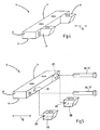
- FIG. 1 shows a punching machine 10 in a highly schematic representation.
- the punching machine 10 has a tool unit 11 according to the invention with a first tool 12 and a second tool 13. It is also set up to carry out the method according to the invention.
- the invention can also be used in cutting machines or other cutting machines.
- the two tools 12, 13 are movable in a working direction A relative to each other.
- the first tool 12 is movably guided in the working direction A on a machine frame 14 and movable via a non-illustrated dargterrorismen drive.
- the second tool 13 or both tools 12, 13 may be arranged to be movable.
- the first tool 12 forms, for example, an upper tool of the punching machine 10.
- the second tool 13 is immovably arranged in the embodiment relative to the machine frame 14 and executed according to the example as a lower tool. By a stroke of the first tool 12 relative to the second tool 13, a mold 15 is punched out of a workpiece 16.
- the workpiece 16 is formed, for example, by a plate or foil and can be supplied in the form of a band of the punching machine 10.
- the punching machine 10 can be used for punching out foils, for example lithium foils for accumulators in the desired shape 15 from the workpiece 16.
- the tool unit 11 has a plurality of second tools 13, which together form a die tool 20.
- the number and arrangement of the second tools 13 depends on the mold 15 which is to be punched out of the workpiece 16.
- Each second tool 13 has a cutting edge 21, wherein connect the cutting edges 21 of adjacent second tools 13 to one another and form a closed die cutting edge.
- a single second tool 13 may be sufficient. Accordingly, a plurality of first tools 12 may be present.
- a punching gap 23 is formed in each case.
- the punching gap 23 In order to avoid loss of quality and, for example, burr formation on the workpiece 16 or the stamped-out mold 15, the punching gap 23 must not exceed a predetermined maximum width.
- the punching gap 23 must be set exactly during initial startup of the punching machine. In the course of operation of the punching machine 10 also wear on at least a first tool 12 and / or the at least one second tool 13 occur, whereby the punching gap 23 can increase.
- a means for adjusting the punching gap 23 is provided, by means of which at least one of the second tools 13 plastically or elastically deformed and thereby a change, in particular a reduction in the width of the respective punching gap 23 can be achieved.
- all second tools 13 are deformable, but this need not necessarily be the case. In some applications, it may be sufficient to apply only a part of the second tools with a respective associated deformation force.
- the second tools 13 are releasably attached to a holding device 27.
- every second tool 13 has at least one support part 28 and, according to the example, two or three support parts 28.
- the support members 28 are in the embodiment according to the figures 3 to 7 on the punching gap 23 and the cutting edge 21 opposite side and project transversely to the working direction A of the cutting edge 21 away.
- Each support member 28 has a rear surface 29, with which it bears against an associated support surface 30 of the holding device 27.
- the rear surface 29 and the associated support surface 30 are parallel to one another and are each designed to be stepless and edgeless. Both the support surface 30, as well as the rear surface 29 extends at an inclination angle ⁇ inclined relative to the working direction A.
- the second tool 13 lies with its side facing away from the first tool 12 bottom 31 on a support surface 32 of the holding device 27.
- the underside 31 and the support surface 32 are preferably designed to be level and edged flat.
- clamping means 33 for example by screw, every second tool 13 in the working direction A is firmly clamped to the holding device 27.
- the second tool 13 is clamped with its underside 31 against the support surface 32.
- the clamping means 33 are preferably designed so that they do not absorb any force transversely to the working direction A.
- At least one tensile and / or pressure means 36 which serves to counteract a movement of the second tool 13 away from the support surface 30 and thereby generate a deformation force F together with the support surface 30, is associated with the second tool 13 to be deformed.
- FIG. 3 are shown schematically as screws 37 running tensile and / or pressure means 36 illustrated. These pass through the holding device 27 and are displaceable in their direction of extension relative to the holding device 27. On the holding device 27, the screws 37 are supported with a head 37 a from where they with their attached to the opposite end of the associated second tool 13 us in the embodiment via a thread 37b are screwed.
- One of the second tools 13 according to FIG. 3 has two cutting edges 21 which form a corner 34.
- Each cutting edge 21 is assigned a support surface 30 of the holding device 27 on the opposite side of the second tool 13.
- This second tool 13 can be adjusted in two directions with a deformation force F for adjusting the width B of the respective punching gap 23.
- Due to the inclination angle ⁇ of the support surface 30 can be generated by the clamping of the second tool 13 with the clamping means 33, a deformation force F on the second tool 13.
- the back surface 29 reaches when clamping in contact with the support surface 30 before the bottom 31 of the second tool on the support surface 32 has reached its end position. Because of the screws 37, however, the second tool can not move away from the inclined support surface 30 during clamping, whereby a deformation force F is generated transversely to the working direction A.
- the deformation force F is sufficiently large in order to deform the second tool 13 transversely to the working direction A in the direction of the gap width of the associated punching gap 23.
- the position of the cutting edge 21 of the respective second tool 13 with respect to the cutting edge 22 of the associated first tool 12 can be changed and thus the width of the punching gap 23 can be adjusted. It is therefore possible, if necessary, to adjust the gap width of the die gap 23 during assembly, initial startup or during ongoing operation. For example, the gap width B can be reduced if it had increased due to wear.
- the inventively effected position changes of the cutting edge 21 of the second tool 13 on the deformation thereof are small and are in the range of 1 to 2 micrometers. However, this displacement of the cutting edge 21 is sufficient to readjust the punching gap 23, which usually has a width of 1 to 3 or 4 microns, in order to obtain a qualitatively perfect and in particular quasi-burr-free punching edge on the mold 15.
- the second tool 13 may be arranged on its side facing away from the support surface 30 a stop surface or other suitable pressure means, so that the second tool 13 between the stop surface and the pressure means and the support surface 30 via a deformation force is deformed.
- the height of the second tool 13 in the working direction A can be reduced from a first height H1 to a second height H2 ( FIGS. 6 and 7 ).
- a layer on the underside 31 of the second tool 13 can be removed, which in FIG. 6 is shown schematically dotted. Since the distance of the support surface 30 relative to the first tool 12 measured measured transversely to the working direction A and smaller towards the support surface 32, so to speak, increases the effective dimension of the second tool 13 transverse to the working direction A in the direction of the width of the cutting gap 23.
- the deformation force F between the support surface 30 and the stop surface 32 increases, whereby the elastic deformation of the relevant second tool 13 and the adjacent, the stop surface 32 having second tool 13 changes.
- the position of the cutting edge 21 with respect to the cutting edge 22 of the first tool 12 can be changed and the width B of the punching gap 23 can be reduced by a difference value D ( FIG. 7 ).
- the second tool 13 and preferably all second tools 13 are made of steel, ceramic, carbide or other suitable materials ( FIG. 4 ). It is also possible to produce or particularly to harden only a region having the cutting edge 21, which can be designated as a tool part 35, made of hard metal. The hardness of the tool part 35 may be greater than the hardness of the remaining part of the second tool 13, in particular of the support parts 28.
- the tool part 35 may also be designed as a separate insert, which is connected to the support members 28.
- the compound can be made soluble or insoluble.
- the area with the underside 31 of the second tool 13 may have a lower hardness than the area that has the cutting edge 21. As a result, the lower side 31 of the second tool 13 can be better processed to reduce the height.
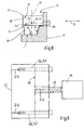
- FIG. 8 shows a modified embodiment of a second tool.
- the support member 28 is not as described above on the cutting edge 21 opposite side, but provided on the bottom 31 of the second tool 13.
- the rear surface 29 present on the support part 28 is assigned to a support surface 30 as described above.
- the base 38 of the support parts 28 adjoining the rear surface 29 is machined, as shown in FIG FIGS. 6 and 7 for the bottom 31 is described.
- the base 38 is associated with the support surface 32 on the holding device 27. Otherwise, the mode of operation and construction correspond to the previously described embodiments, so that reference is made to the above description.
- a modified second tool 13 is shown. It has, for example, a substantially cuboid contour.
- the rear surface 29 and the abutting support surface 29 of the holding device 27 are not inclined with respect to the working direction A.
- This is connected to a force-generating unit 40, which may have, for example, an electric motor or hydraulic or pneumatic means for generating power.
- the tension and / or pressure means 36 may be, for example, a driven by an electric motor spindle, which is connected to the second tool 13.
- the force generating unit 40 to adjust the width B of the punching gap 23, the deformation force F set.
- a manual adjusting means may be present.
- the screws 37 can be used as tension and / or pressure means 36 and the deformation force F can be adjusted manually via the screws 37.
- the width B of the punching gap of the associated second tool 13 can also be regulated.
- the width B can be measured via a particularly optical measuring device and in one Control unit are compared with a setpoint. In case of deviations, the control unit activates the force-generating unit 40 to increase or decrease the deformation force F.
- FIGS. 8 and 9 a separate insert may be provided as a tool part 35.
- Supporting parts 28 may also be present both on the underside 31 and on the side of the second tool 13 opposite the cutting edge 21 (FIG. FIGS. 3 to 7 and 8th ).
- the deformation force F it is possible to set the deformation force F at different locations of a second tool 13 of different sizes. This is done, for example, to adapt the width B punching gap 23 to a non-straight course of the associated edge of a first tool 12.
- the second tool 13 for example, a plurality of tensile and / or pressure means 36 associated by means of which in each case a desired amount for a local deformation force F is adjustable.
- the invention relates to a tool unit 11 and a method for changing the width B of a punching gap 23 between a first tool 12 and a second tool 13 of the tool unit 11.
- a plurality of second tools 13 are provided, which together form a die tool 20 with a circumferential die cutting edge, in which the first tool 12 can engage with its cutting edge 22.
- a punching gap 23 is formed in each case with a width B between the cutting edges 21, 22nd measured transversely to a working direction A.
- the first tool 12 and the second tool 13 are moved relative to each other.
- About clamping means 33 can act on a second tool 13 acting deformation force transverse to the direction A, whereby the position of the respective cutting edge 21 and thus the width B of the punching gap 23 change and set.
Description
Die Erfindung betrifft ein Verfahren und eine Werkzeugeinheit zur Einstellung eines Stanzspalts für eine Stanz- oder Schneidmaschine. Die Werkzeugeinheit weist ein erstes Werkzeug und ein zweites Werkzeug auf. Beim Schneiden oder Stanzen werden die beiden Werkzeuge relativ zueinander bewegt. Eine Schneidkante am ersten Werkzeug und eine Schneidkante am zweiten Werkzeug arbeiten zusammen, um ein Werkstück, beispielsweise eine Folie, zu Schneiden oder zu Stanzen. Es können auch mehrere erste und/oder zweite Werkzeuge vorhanden sein.The invention relates to a method and a tool unit for setting a punching gap for a punching or cutting machine. The tool unit has a first tool and a second tool. When cutting or punching the two tools are moved relative to each other. A cutting edge on the first tool and a cutting edge on the second tool work together to cut or punch a workpiece, such as a foil. There may also be a plurality of first and / or second tools.
Derartige Schneid- oder Stanzmaschinen sind an sich bekannt. Beispielsweise beschreibt
Bei der ersten Inbetriebnahme der Stanz- oder Schneidmaschine muss der Spalt zwischen dem ersten und dem zweiten Werkzeug eingestellt werden. Außerdem gelangen die beiden Werkzeuge während des Betriebs der Stanz- oder Schneidmaschine bei jedem Arbeitshub in Kontakt mit dem zu stanzenden Material und nutzen sich ab. Dies führt dazu, dass ein Stanz- oder Schneidspalt zwischen dem ersten Werkzeug und dem zweiten Werkzeug zunimmt. Somit ist bei der Erstinbetriebnahme und während des Betriebs die Einstellung des Stanz- oder Schneidspalts notwendig. Eine exakte Spaltbreite ist insbesondere bei Präzisionswerkzeugen von großer Bedeutung. Ist oder wird der Spalt zu groß, sinkt die Qualität der geschnittenen bzw. gestanzten Kante am Werkstück, z.B. kann sich am Werkstück ein Grat bilden. Eine solche Gratbildung ist unerwünscht. Beispielsweise kann ein solcher Grat beim Ausstanzen von Folien für Akkumulatoren zu Kurzschlüssen zwischen benachbarten Folien führen. Das Überschreiten eines Maximalwerts der Spaltbreite ist daher zu vermeiden.When first using the punching or cutting machine, the gap between the first and the second must be Tool to be adjusted. In addition, the two tools get during the operation of the punching or cutting machine at each stroke in contact with the material to be punched and worn down. This causes a punching or cutting gap between the first tool and the second tool to increase. Thus, the setting of the punching or cutting gap is necessary during initial startup and during operation. An exact gap width is of great importance especially for precision tools. If the gap is or becomes too large, the quality of the cut or punched edge on the workpiece decreases, eg a burr may form on the workpiece. Such burr formation is undesirable. For example, such a ridge when punching out foils for accumulators lead to short circuits between adjacent foils. Exceeding a maximum value of the gap width is therefore to be avoided.
Aus
Eine aus
Somit kann es als eine Aufgabe der vorliegenden Erfindung betrachtet werden, ein Verfahren und eine Werkzeugeinheit für eine Schneid- oder Stanzmaschine zu schaffen, bei der der Stanz- oder Schneidspalt sehr einfach eingestellt werden kann.Thus, it can be considered an object of the present invention to provide a method and a tool unit for a cutting or punching machine in which the punching or cutting gap can be set very easily.
Diese Aufgabe wird durch ein Verfahren mit den Merkmalen des Patentanspruches 1 sowie eine Werkzeugeinheit mit den Merkmalen des Patentanspruches 7 gelöst.This object is achieved by a method having the features of
Erfindungsgemäß wird durch Mittel zur Einstellung einer Verformungskraft zumindest das zweite Werkzeug elastisch verformt und dadurch der Stanz- oder Schneidspalt eingestellt. Insbesondere wird durch Vergrößerung der Verformungskraft eine durch Verschleiß aufgetretene Vergrößerung des Stanzspaltes zumindest teilweise kompensiert. Die Verformungskraft ist insbesondere quer zur Arbeitsrichtung und mithin quer zur Bewegungsrichtung des ersten oder zweiten Werkzeuges ausgerichtet. Zusätzlich kann auch das erste Werkzeug durch zugeordnete Mittel mit einer Verformungskraft beaufschlagt werden, um den Stanz- oder Schneidspalt einzustellen. Die Ausgestaltungen, die nachfolgend im Hinblick auf das zweite Werkzeug erläutert werden, können auch beim ersten Werkzeug zur Anwendung kommen.According to the invention, at least the second tool is elastically deformed by means for adjusting a deformation force, thereby setting the punching or cutting gap. In particular, enlargement of the deformation force compensates at least partially for an enlargement of the die gap which has occurred due to wear. The deformation force is aligned in particular transversely to the working direction and thus transversely to the direction of movement of the first or second tool. In addition, the first tool can be acted upon by associated means with a deformation force to adjust the punching or cutting gap. The embodiments below with regard to can be explained on the second tool can also be used for the first tool.
Die Verformung kann plastisch oder elastisch sein. Insbesondere bei der Einstellung der Spaltbreite im Rahmen der Erstinbetriebnahme kann das betreffende Werkzeug auch plastisch verformt werden. Eine derartige elastische oder plastische Verformung kann beispielsweise durch Einspannmittel, die das zweite Werkzeug an einer Halteeinrichtung einspannen, sehr einfach erzeugt werden. Durch die Erfindung entfällt ein aufwendiges Bearbeiten des zweiten Werkzeugs, insbesondere dessen Schneid- oder Stanzkante, um den Stanz- oder Schneidspalt auf die gewünschte Größe einzustellen. Dadurch kann eine äußerst exakte Einstellung des Spalts erfolgen.The deformation can be plastic or elastic. In particular, when setting the gap width in the context of initial commissioning, the tool in question can also be plastically deformed. Such elastic or plastic deformation can be generated very easily, for example by means of clamping means, which clamp the second tool to a holding device. The invention eliminates a complex processing of the second tool, in particular its cutting or punching edge to adjust the punching or cutting gap to the desired size. This allows a very accurate adjustment of the gap.
Die Verformungskraft wird dadurch erzeugt, dass sich das zweite Werkzeug in einer Richtung quer zur Arbeitsrichtung auf der dem Stanz- oder Schneidspalt abgewandten Seite gegen eine Abstützfläche gedrückt und wird. Bei der Werkzeugeinheit ist zumindest ein Zug- und/oder Druckmittel vorhanden, das das zweite Werkzeug an einer Bewegung quer von der Abstützfläche weg hindert. Durch Einspannen des zweiten Werkzeugs mit einer Einspannkraft in Arbeitsrichtung, bewirkt die Abstützfläche und das damit zusammenwirkende Zug- und/oder Druckmittel eine Verformung des zweiten Werkzeugs quer zur Arbeitsrichtung. Insbesondere verläuft dabei die Abstützfläche unter einem Neigungswinkel geneigt schräg zur Arbeitsrichtung. Dadurch wird eine einfache und exakte Möglichkeit geschaffen, den Stanz- oder Schneidspalt durch elastische oder plastische Verformung des zweiten Werkzeugs zu variieren.The deformation force is generated in that the second tool is pressed in a direction transverse to the working direction on the side facing away from the punching or cutting gap against a support surface and is. At least one tensile and / or pressure means is present in the tool unit, which prevents the second tool from moving transversely away from the support surface. By clamping the second tool with a clamping force in the working direction, the support surface and the co-operating tensile and / or pressure means causes a deformation of the second tool transversely to the working direction. In particular, the support surface is inclined at an inclination angle inclined to the working direction. This provides a simple and accurate way to vary the punching or cutting gap by elastic or plastic deformation of the second tool.
Das zweite Werkzeug weist wenigstens ein Abstützteil auf, das sich mit einer Rückfläche an der zugeordneten Abstützfläche der Halteeinrichtung für das zweite Werkzeug abstützt. Vorzugsweise verläuft die Rückfläche unter dem gleichen Neigungswinkel geneigt zur Arbeitsrichtung und mithin parallel zur Abstützfläche. Die Abstützfläche und die Rückfläche sind vorzugsweise stufenlos und kantenlos eben ausgeführt. Sie bilden sozusagen ein Kraftübertragungsmittel, das in der Richtung quer zur Arbeitsrichtung eine Kraft auf das zweite Werkzeug in Richtung zum Stanz-oder Schneidspalt übertragen kann. Mithilfe des wenigstens einen Zug- und/oder Druckmittels, das der Werkzeugbewegung von der Abstützfläche weg entgegenwirkt, entsteht die Verformung des zweiten Werkzeugs.The second tool has at least one support part which projects with a rear surface on the associated support surface the holding device for the second tool is supported. Preferably, the rear surface extends at the same inclination angle inclined to the working direction and thus parallel to the support surface. The support surface and the back surface are preferably designed to be stepless and edgeless. They form, so to speak, a force transmission means which can transmit a force in the direction transverse to the working direction on the second tool in the direction of the punching or cutting gap. By means of the at least one tension and / or pressure means, which counteracts the tool movement away from the support surface, the deformation of the second tool is created.
Das Zug- und/oder Druckmittel kann durch Anker oder Schrauben oder ähnliche Mittel gebildet sein. Alternativ oder zusätzlich kann als Druckmittel auch eine Anschlagfläche vorhanden sein, an der das zweite Werkzeug auf seiner dem Stanz- oder Schneidspalt zugewandten Seite anliegt. Die Anschlagfläche kann insbesondere benachbart zum Stanz- oder Schneidspalt, beispielsweise in Verlängerung des Stanzspaltes daneben angeordnet.The tension and / or pressure means may be formed by anchors or screws or similar means. Alternatively or additionally, as a pressure means also a stop surface may be present, against which the second tool rests on its side facing the punching or cutting gap. The stop surface may in particular adjacent to the punching or cutting gap, for example, arranged in extension of the punching gap next to it.
Die Verformungskraft kann bei einer Ausführung auch durch eine Krafterzeugungseinheit erzeugt werden, die beispielsweise elektrische, mechanische, hydraulische oder pneumatische Mittel aufweist und vorzugsweise elektrisch angesteuert werden kann. Beispielsweise kann die Krafterzeugungseinheit eine Motor-Spindel-Einheit aufweisen.In one embodiment, the deformation force can also be generated by a force-generating unit which has, for example, electrical, mechanical, hydraulic or pneumatic means and can preferably be electrically controlled. For example, the force-generating unit may have a motor-spindle unit.
Bei einer bevorzugten Ausführungsform können mehrere zweite Werkzeuge vorhanden sein, die gemeinsam ein Matrizenwerkzeug bilden. Dabei können die Schneidkanten zweier benachbarter zweiter Werkzeuge aneinander angrenzen und insbesondere eine nahezu geschlossene Matrizenschneidkante bilden. Die zweiten Werkzeuge können mit geringem Abstand von insbesondere wenigen Mikrometern nebeneinander angeordnet sein oder sich berühren ohne eine zur Verformung ausreichend große Kraft aufeinander auszuüben. In den von der Matrizenschneidkante umschlossenen Raum zwischen den zweiten Werkzeugen kann das erste Werkzeug eingreifen.In a preferred embodiment, a plurality of second tools may be present, which together form a die tool. In this case, the cutting edges of two adjacent second tools adjacent to each other and in particular form an almost closed Matrizenschneidkante. The second tools can be at close range be arranged in particular of a few micrometers next to each other or touch without exercising a sufficiently large force for deformation force each other. The first tool can engage in the space between the second tools enclosed by the die cutting edge.
Die Verformungskraft wird bei dem erfindungsgemäßen Verfahren dadurch verändert, dass die Höhe eines zweiten Werkzeugs zumindest abschnittsweise verringert wird, nämlich am wenigstens einen Abstützteil des zweiten Werkzeugs. Dadurch kann die Abmessung des zweiten Werkzeugs an der Stelle mit der geringsten Abmessung zwischen der Abstützfläche und der Schneidkante quer zur Arbeitsrichtung vergrößert werden. Die Verformungskraft nimmt dadurch zu, wodurch sich die Breite des Stanz- oder Schneidspalts verändert und insbesondere verringert.The deformation force is changed in the method according to the invention in that the height of a second tool is at least partially reduced, namely at least one support part of the second tool. Thereby, the dimension of the second tool at the position with the smallest dimension between the support surface and the cutting edge can be increased transversely to the working direction. The deformation force thereby increases, whereby the width of the punching or cutting gap changed and in particular reduced.
Das zweite Werkzeug besteht vorzugsweise aus Stahl, Keramik, Hartmetall oder einem abhängig vom zu stanzenden Material anderen geeigneten Werkstoff. Zumindest ein Werkzeugteil, das die Schneidkante des zweiten Werkzeugs aufweist, ist aus einem der genannten Materialien hergestellt und/oder weist eine Härte auf, die größer ist als die Härte des Abstützteils des zweiten Werkzeugs. Der Werkzeugteil kann auch als separater Einsatz ausgeführt sein, der fest mit dem Abstützteil verbunden ist. Beispielsweise kann der zur Veränderung der Höhe des zweiten Werkzeugs vorgesehene Bereich an der Unterseite des zweiten Werkzeugs eine geringere Härte aufweisen, als der die Schneidkante aufweisende Werkzeugteil, so dass eine Höhenreduzierung, beispielsweise durch Schleifen, in einem weniger harten Bereich des zweiten Werkzeugs erfolgen kann.The second tool is preferably made of steel, ceramic, carbide or other depending on the material to be punched material. At least one tool part having the cutting edge of the second tool is made of one of said materials and / or has a hardness that is greater than the hardness of the support part of the second tool. The tool part can also be designed as a separate insert, which is firmly connected to the support part. For example, the area provided for changing the height of the second tool on the underside of the second tool may have a lower hardness than the cutting edge having tool part, so that a reduction in height, for example by grinding, can be done in a less hard area of the second tool.
Vorteilhafte Ausgestaltungen des erfindungsgemäßen Verfahrens sowie der erfindungsgemäßen Vorrichtung ergeben sich aus den abhängigen Patentansprüchen und der Beschreibung. Die Beschreibung beschränkt sich auf wesentliche Merkmale der Erfindung. Nachfolgend werden bevorzugte Ausführungen des Verfahrens und der Vorrichtung anhand der beigefügten Zeichnung im Einzelnen erläutert. Es zeigen:
-
Figur 1 -
Figur 2 eine schematische Darstellung eines zu stanzenden Werkstücks in Draufsicht, -
Figur 3 ein Matrizenwerkzeug mit mehreren zweiten Werkzeugen in schematischer Ansicht in Arbeitsrichtung, -
Figuren 4 und 5 jeweils eine perspektivische Darstellung eines Ausführungsbeispiels eines zweiten Werkzeugs, -
Figuren 6 und 7 schematische Darstellungen eines zweiten Werkzeugs mit unterschiedlichen Verformungskräften zur Einstellung des Stanzspaltes, -
Figuren 8 eine teilgeschnittene schematische Seitenansicht eines alternativen Ausführungsbeispiels eines zweiten Werkzeugs und -
Figur 9 das zweite Werkzeug nachFiguren 3 bis 7 mit einer Krafterzeugungseinheit zur Erzeugung der Verformungskraft.
-
FIG. 1 a schematic block diagram similar representation of a punching machine, -
FIG. 2 a schematic representation of a workpiece to be punched in plan view, -
FIG. 3 a die tool with several second tools in a schematic view in the working direction, -
FIGS. 4 and 5 each a perspective view of an embodiment of a second tool, -
FIGS. 6 and 7 schematic representations of a second tool with different deformation forces for adjusting the punching gap, -
FIGS. 8 a partially sectioned schematic side view of an alternative embodiment of a second tool and -
FIG. 9 the second tool afterFIGS. 3 to 7 with a force generating unit for generating the deformation force.
Die beiden Werkzeuge 12, 13 sind in einer Arbeitsrichtung A relativ zueinander bewegbar. Beim Ausführungsbeispiel ist das erste Werkzeug 12 geführt beweglich in Arbeitsrichtung A an einem Maschinengestell 14 gelagert und über einen nicht näher dargstellten Antrieb bewegbar. Alternativ kann auch das zweite Werkzeug 13 oder es können beide Werkzeuge 12, 13 bewegbar angeordnet sein. Das erste Werkzeug 12 bildet beispielsgemäß ein Oberwerkzeug der Stanzmaschine 10. Das zweite Werkzeug 13 ist beim Ausführungsbeispiel unbeweglich gegenüber dem Maschinengestell 14 angeordnet und beispielsgemäß als Unterwerkzeug ausgeführt. Durch einen Hub des ersten Werkzeugs 12 gegenüber dem zweiten Werkzeug 13 wird eine Form 15 aus einem Werkstück 16 ausgestanzt. Das Werkstück 16 ist beispielsgemäß durch eine Platte oder Folie ausgebildet und kann in Form eines Bandes der Stanzmaschine 10 zugeführt werden. Insbesondere kann die Stanzmaschine 10 zum Ausstanzen von Folien, beispielsweise Lithiumfolien für Akkumulatoren in der gewünschten Form 15 aus dem Werkstück 16 dienen.The two
Bei dem hier beschriebenen Ausführungsbeispiel weist die Werkzeugeinheit 11 mehrere zweite Werkzeuge 13 auf, die gemeinsam ein Matrizenwerkzeug 20 bilden. Die Anzahl und Anordnung der zweiten Werkzeuge 13 hängt von der Form 15 ab, die aus dem Werkstück 16 ausgestanzt werden soll. Jedes zweite Werkzeug 13 weist eine Schneidkante 21 auf, wobei die Schneidkanten 21 benachbarter zweiter Werkzeuge 13 aneinander anschließen und eine geschlossene Matrizenschneidkante bilden. Zum Ausführen eines einfachen Schnitts in das Werkstück 16 kann auch ein einziges zweites Werkzeug 13 ausreichen. Entsprechend können auch mehrere erste Werkzeuge 12 vorhanden sein.In the exemplary embodiment described here, the
Zwischen der Schneidkante 21 jedes zweiten Werkzeugs 13 und einer Schneidkante 22 des ersten Werkzeugs 12 ist jeweils ein Stanzspalt 23 gebildet. Um Qualitätseinbußen und beispielsweise eine Gratbildung am Werkstück 16 bzw. der ausgestanzten Form 15 zu vermeiden, darf der Stanzspalt 23 eine vorgegebene Maximalbreite nicht überschreiten. Der Stanzspalt 23 muss bei der Erstinbetriebnahme der Stanzmaschine genau eingestellt werden. Im Laufe des Betriebs der Stanzmaschine 10 treten auch Verschleißerscheinungen am wenigstens einen ersten Werkzeug 12 und/oder dem wenigstens einen zweiten Werkzeug 13 auf, wodurch sich der Stanzspalt 23 vergrößern kann. Erfindungsgemäß ist ein Mittel zur Einstellung des Stanzspalts 23 vorgesehen, mittels dem wenigstens eines der zweiten Werkzeuge 13 plastisch oder elastisch verformt und dadurch eine Veränderung, insbesondere eine Verringerung der Breite des betreffenden Stanzspaltes 23 erreicht werden kann. Beim beschriebenen Ausführungsbeispiel sind alle zweiten Werkzeuge 13 verformbar, was aber nicht zwingend der Fall sein muss. Bei einigen Anwendungen kann es ausreichend sein, lediglich einen Teil der zweiten Werkzeuge mit einer jeweils zugeordneten Verformungskraft zu beaufschlagen.Between the
Die zweiten Werkzeuge 13 sind an einer Halteeinrichtung 27 lösbar befestigt. Zu diesem Zweck weist jedes zweite Werkzeug 13 wenigstens ein Abstützteil 28 und beispielsgemäß zwei oder drei Abstützteile 28 auf. Die Abstützteile 28 befinden sich bei dem Ausführungsbeispiel gemäß den Figuren 3 bis 7 auf der dem Stanzspalt 23 bzw. der Schneikante 21 abgewandten Seite und ragen quer zur Arbeitsrichtung A von der Schneidkante 21 weg. Jedes Abstützteil 28 hat eine Rückfläche 29, mit der es an einer zugeordneten Abstützfläche 30 der Halteeinrichtung 27 anliegt. Die Rückfläche 29 und die zugeordnete Abstützfläche 30 verlaufen parallel zueinander und sind jeweils stufenlos und kantenlos eben ausgeführt. Sowohl die Abstützfläche 30, als auch die Rückfläche 29 verläuft unter einem Neigungswinkel α geneigt gegenüber der Arbeitsrichtung A.The
Das zweite Werkzeug 13 liegt mit seiner dem ersten Werkzeug 12 abgewandten Unterseite 31 auf einer Auflagefläche 32 der Halteeinrichtung 27 auf. Die Unterseite 31 und die Auflagefläche 32 sind vorzugsweise stufen- und kantenlos eben ausgeführt. Mithilfe von Einspannmitteln 33, beispielsweise durch Schraubverbindungen, wird jedes zweite Werkzeug 13 in Arbeitsrichtung A fest an der Halteeinrichtung 27 verspannt. Beispielsgemäß wird das zweite Werkzeug 13 mit seiner Unterseite 31 gegen die Auflagefläche 32 gespannt. Die Einspannmittel 33 sind dabei vorzugsweise so ausgeführt, dass sie keine Kraft quer zur Arbeitsrichtung A aufnehmen.The
Dem zu verformenden zweiten Werkzeug 13 ist jeweils mindestens ein Zug- und/oder Druckmittel 36 zugeordnet, das dazu dient, einer Bewegung des zweiten Werkzeugs 13 von der Abstützfläche 30 weg entgegenzuwirken und dabei gemeinsam mit der Abstützfläche 30 eine Verformungskraft F zu erzeugen. In
Eines der zweiten Werkzeuge 13 gemäß
Aufgrund des Neigungswinkels α der Abstützfläche 30 kann durch das Einspannen des zweiten Werkzeugs 13 mit den Einspannmitteln 33 eine Verformungskraft F auf das zweite Werkzeug 13 erzeugt werden. Die Rückfläche 29 gelangt beim Einspannen in Kontakt mit der Abstützfläche 30 bereits bevor die Unterseite 31 des zweiten Werkzeugs auf der Auflagefläche 32 ihre Endlage erreicht hat. Wegen der Schrauben 37 kann das zweite Werkzeug sich aber beim Einspannen nicht von der schrägen Abstützfläche 30 weg bewegen, wodurch eine Verformungskraft F quer zur Arbeitsrichtung A erzeugt wird. Die Verformungskraft F ist dabei ausreichend groß, um das zweite Werkzeug 13 quer zur Arbeitsrichtung A in Richtung der Spaltbreite des zugeordneten Stanzspaltes 23 zu verformen. Aufgrund dieser Verformung kann die Lage der Schneidkante 21 des betreffenden zweiten Werkzeugs 13 gegenüber der Schneidkante 22 des zugeordneten ersten Werkzeugs 12 verändert und somit die Breite des Stanzspaltes 23 eingestellt werden. Es ist daher möglich, falls notwenig, die Spaltbreite des Stanzspaltes 23 bei der Montage, der Erstinbetriebnahme oder während des Laufenden Betriebs einzustellen. Beispielsweise kann die Spaltbreite B verringert werden, wenn diese durch Verschleiß zugenommen hatte.Due to the inclination angle α of the
Die erfindungsgemäß bewirkten Positionsänderungen der Schneidkante 21 des zweiten Werkzeugs 13 über dessen Verformung sind klein und liegen im Bereich von 1 bis 2 Mikrometern. Diese Verschiebung der Schneidkante 21 ist aber ausreichend, um den Stanzspalt 23, der üblicherweise eine Breite von 1 bis 3 oder bis 4 Mikrometer aufweist, nachzujustieren, um eine qualitativ einwandfreie und insbesondere quasi gratfreie Stanzkante an der Form 15 zu erhalten.The inventively effected position changes of the
Anstelle einer Schraube 37 oder eines anderen Zugmittels kann dem zweiten Werkzeug 13 auf seiner der Abstützfläche 30 abgewandten Seite eine Anschlagfläche oder ein anderes geeignetes Druckmittel angeordnet sein, so dass das zweite Werkzeug 13 zwischen der Anschlagfläche bzw. dem Druckmittel und der Abstützfläche 30 über eine Verformungskraft verformt wird.Instead of a screw 37 or another traction means, the
Um die Verformungskraft F eines zweiten Werkzeuges und/oder die Position dessen Schneidkante 21 zu verändern, wird dieses beim Ausführungsbeispiel zumindest im Bereich der Abstützteile 28 an seiner Unterseite 31 bearbeitet. Dadurch kann die Höhe des zweiten Werkzeugs 13 in Arbeitsrichtung A von einer ersten Höhe H1 auf eine zweite Höhe H2 reduziert werden (
Das zweite Werkzeug 13 und vorzugsweise alle zweiten Werkzeuge 13 bestehen aus Stahl, Keramik, Hartmetall oder andere geeignete Werkstoffe (
Wie in
Bei einer bevorzugten Ausführungsform kann der Bereich mit der Unterseite 31 des zweiten Werkzeugs 13 eine geringere Härte aufweisen, als der Bereich, der die Schneidkante 21 aufweist. Dadurch lässt sich die Unterseite 31 des zweiten Werkzeugs 13 zur Reduzierung der Höhe besser bearbeiten.In a preferred embodiment, the area with the
In
In Abwandlung zu dem in
Mithilfe der Krafterzeugungseinheit kann die Breite B des Stanzspaltes des zugeordneten zweiten Werkzeugs 13 auch geregelt werden. Beispielsweise kann der Breite B über eine insbesondere optische Messeinrichtung gemessen und in einer Steuereinheit mit einem Sollwert verglichen werden. Bei Abweichungen steuert die Steuereinheit die Krafterzeugungseinheit 40 zur Erhöhung oder Verringerung der Verformungskraft F an.By means of the force generating unit, the width B of the punching gap of the associated
Die Merkmale der unterschiedlichen Ausführungsbeispiele des zweiten Werkzeugs 13 können auch miteinander kombiniert werden. Beispielsweise kann auch bei den Ausführungen nach
Bei allen Ausführungsformen ist es möglich, die Verformungskraft F an verschiedenen Stellen eines zweiten Werkzeugs 13 unterschiedlich groß einzustellen. Dies erfolgt beispielsweise zur Anpassung der Breite B Stanzspaltes 23 an einen nicht geraden Verlauf der zugeordneten Kante eines ersten Werkzeugs 12. Hierfür sind dem zweiten Werkzeug 13 beispielsweise mehrere Zug- und/oder Druckmittel 36 zugeordnet, mittels denen jeweils ein gewünschter Betrag für eine lokale Verformungskraft F einstellbar ist.In all embodiments, it is possible to set the deformation force F at different locations of a
Die Erfindung betrifft eine Werkzeugeinheit 11 und ein Verfahren zur Änderung der Breite B eines Stanzspaltes 23 zwischen einem ersten Werkzeug 12 und einem zweiten Werkzeug 13 der Werkzeugeinheit 11. Vorzugsweise sind mehrere zweite Werkzeuge 13 vorhanden, die gemeinsam ein Matrizenwerkzeug 20 mit einer umlaufenden Matrizenschneidkante bilden, in die das erste Werkzeug 12 mit seiner Schneidkante 22 eingreifen kann. Zwischen der Schneidkante 22 des ersten Werkzeugs 12 und der jeweiligen Schneidkante 21 eines zweiten Werkzeugs 13 ist jeweils ein Stanzspalt 23 mit einer Breite B gebildet, die zwischen den Schneidkanten 21, 22 quer zu einer Arbeitsrichtung A gemessen wird. In Arbeitsrichtung A werden das erste Werkzeug 12 und das zweite Werkzeug 13 relativ zueinander bewegt. Über Einspannmittel 33 lässt sich eine auf ein zweites Werkzeug 13 einwirkende Verformungskraft quer zur Arbeitsrichtung A bewirken, wodurch sich die Position der betreffenden Schneidkante 21 und mithin die Breite B des Stanzspaltes 23 verändern und einstellen lässt.The invention relates to a
- 1010
- Stanzmaschinepunching machine
- 1111
- Werkzeugeinheittool unit
- 1212
- erstes Werkzeugfirst tool
- 1313
- zweites Werkzeugsecond tool
- 1414
- Maschinengestellmachine frame
- 1515
- Formshape
- 1616
- Werkstückworkpiece
- 2020
- Matrizenwerkzeugdie tool
- 2121
- Schneidkante des zweiten WerkzeugsCutting edge of the second tool
- 2222
- Schneidkante des ersten WerkzeugsCutting edge of the first tool
- 2323
- Stanzspaltpunching gap
- 2727
- Halteeinrichtungholder
- 2828
- Abstützteilsupporting part
- 2929
- Rückflächerear surface
- 3030
- Abstützflächesupporting
- 3131
- Unterseitebottom
- 3232
- Auflageflächebearing surface
- 3333
- Einspannmittelchuck
- 3434
- Eckecorner
- 3535
- Werkzeugteiltool part
- 3636
- Zug- und/oder DruckmittelTensile and / or pressure medium
- 3737
- Schraubescrew
- 37a37a
- Kopfhead
- 37b37b
- Gewindethread
- 3838
- GrundflächeFloor space
- 4040
- KrafterzeugungseinheitForce generating unit
- αα
- Neigungswinkeltilt angle
- AA
- Arbeitsrichtungworking direction
- BB
- Breite des StanzspaltesWidth of the cutting gap
- DD
- Differenzwertdifference value
- FF
- Verformungskraftdeforming force
- H1H1
- erster Höhenwertfirst altitude value
- H2H2
- zweiter Höhenwertsecond altitude value
Claims (11)
- Method for adjusting a punching or cutting gap (23) on a tool unit (11) of a punching or cutting machine (10), wherein the tool unit (11) has a first tool (12) and at least one second tool (13) which are moved relative to each other in a working direction (A) for punching or cutting, wherein the punching or cutting gap (23) is present transversely to the working direction (A) between the first tool (12) and the second tool (13), wherein the second tool (13) has at least one supporting part (28) which rests with a back face (29) on a support face (30) of a holding device (27) for the second tool (13), wherein to adjust the punching or cutting gap (23), the height (H1, H2) of the support part (28) of the second tool (13) is reduced in the working direction (A),
and wherein the punching or cutting gap (23) is adjusted by deformation of the second tool (13). - Method according to claim 1, characterised in that a deformation force (F) acts on the second tool (13) transversely to the working direction (A).
- Method according to claim 1 or 2, characterised in that the deformation force (F) is generated via a force generating unit (40) which has electric and/or hydraulic and/or pneumatic means for generating the deformation force (F).
- Method according to any of the preceding claims, characterised in that the support face (30) is oriented at a tilt angle (α) obliquely to the working direction (A).
- Method according to any of the preceding claims, characterised in that the second tool (13) rests with its side facing the punching or cutting gap (23) on a stop face.
- Method according to claim 5, characterised in that the second tool (13) is deformed by clamping the second tool (13) between the stop face and the support face (30).
- Tool unit (11) for a punching or cutting machine (10),
with a first tool (12) and a second tool (13), wherein the first tool (12) and the second tool (13) can be moved relative to each other in a working direction (A) for punching or cutting,
with a punching or cutting gap (23) transverse to the working direction (A) between the first tool (12) and the second tool (13),
wherein the second tool (13) has a support part (28) and rests with the support part (28) in a direction transverse to the working direction (A) on the side facing away from the punching or cutting gap (23), wherein at least one tension and/or compression means (36, 37) is assigned to the second tool (13) and counters a movement of the second tool (13) away from the support face (30),
wherein a deformation force (F) which deforms the second tool (13) for adjusting the punching gap (23) is generated by clamping the second tool (13) between the tension and/or compression means (36) and the support face (30). - Tool unit according to claim 7, characterised in that the support face (30) runs obliquely to the working direction (A).
- Tool unit according to claim 7 or 8, characterised in that a plurality of second tools (13) is present which together form a die tool (20).
- Tool unit according to claim 9, characterised in that at least some of the second tools (13) are exposed to a deformation force (F).
- Tool unit according to any of claims 7 to 10, characterised in that the cutting edge (21) of the second tool (13) is present on a tool part (35), the hardness of which is greater than the hardness of the support part (28).
Applications Claiming Priority (2)
| Application Number | Priority Date | Filing Date | Title |
|---|---|---|---|
| DE102012109434.9A DE102012109434A1 (en) | 2012-10-04 | 2012-10-04 | Method and tool unit for setting a punching gap |
| PCT/EP2013/070729 WO2014053643A1 (en) | 2012-10-04 | 2013-10-04 | Method and tool unit for setting a punching gap |
Publications (2)
| Publication Number | Publication Date |
|---|---|
| EP2903790A1 EP2903790A1 (en) | 2015-08-12 |
| EP2903790B1 true EP2903790B1 (en) | 2016-09-14 |
Family
ID=49448111
Family Applications (1)
| Application Number | Title | Priority Date | Filing Date |
|---|---|---|---|
| EP13779760.1A Active EP2903790B1 (en) | 2012-10-04 | 2013-10-04 | Method and tool unit for the adjustment of the tool unit |
Country Status (9)
| Country | Link |
|---|---|
| US (1) | US9796103B2 (en) |
| EP (1) | EP2903790B1 (en) |
| JP (1) | JP6243915B2 (en) |
| KR (1) | KR102193253B1 (en) |
| CN (1) | CN105102192B (en) |
| DE (1) | DE102012109434A1 (en) |
| HU (1) | HUE031310T2 (en) |
| PL (1) | PL2903790T3 (en) |
| WO (1) | WO2014053643A1 (en) |
Families Citing this family (9)
| Publication number | Priority date | Publication date | Assignee | Title |
|---|---|---|---|---|
| EP3246140B1 (en) * | 2016-05-16 | 2019-06-26 | Tetra Laval Holdings & Finance S.A. | Cutting unit and method for cutting |
| KR102341464B1 (en) * | 2018-05-04 | 2021-12-22 | 주식회사 엘지에너지솔루션 | Cutting device and method for electrode sheet |
| CN108746317A (en) * | 2018-05-30 | 2018-11-06 | 大连理工大学 | A kind of blanking apparatus that can continuously adjust gap |
| KR101939706B1 (en) * | 2018-06-28 | 2019-01-18 | 주식회사 지에스피컴퍼니 | Film cutting equipment and film cutting equipment coating layer forming method |
| DE102018122717A1 (en) * | 2018-09-17 | 2020-03-19 | Trumpf Werkzeugmaschinen Gmbh + Co. Kg | Process for cutting tubes in a laser tube cutting machine and laser tube cutting machine |
| CN112091056B (en) * | 2020-08-24 | 2023-01-10 | 珠海格力精密模具有限公司 | Punching method |
| CN113523091B (en) * | 2021-06-23 | 2022-07-19 | 东风柳州汽车有限公司 | 7-shaped hole machining method |
| CN114101784A (en) * | 2021-12-21 | 2022-03-01 | 新疆八一钢铁股份有限公司 | Elastic flat fixed-length shearing method for stepped shear blades |
| CN116984474B (en) * | 2023-09-20 | 2023-12-19 | 山西中航锦恒科技有限公司 | Punching and cutting device for cable processing |
Citations (1)
| Publication number | Priority date | Publication date | Assignee | Title |
|---|---|---|---|---|
| DE19933497A1 (en) * | 1999-07-16 | 2001-01-18 | Rieter Automatik Gmbh | Gap adjustment device and method |
Family Cites Families (32)
| Publication number | Priority date | Publication date | Assignee | Title |
|---|---|---|---|---|
| DE544605C (en) | 1929-11-28 | 1932-02-19 | Wilhelm Reinacher Dipl Ing | Device for adjusting the height of the lower knife in sheet metal shears |
| US3913438A (en) * | 1973-02-09 | 1975-10-21 | Fabco Inc | Wedge actuated cutting and/or forming tools |
| US4104941A (en) * | 1976-09-21 | 1978-08-08 | S. B. Whistler & Sons, Inc. | Assembly for enabling close tolerance punching with a reusable system |
| DE3012486C2 (en) | 1980-03-31 | 1985-04-18 | Jürgen 1000 Berlin Schulz | Device in the manner of a punch or press |
| JPS5861929A (en) * | 1981-10-07 | 1983-04-13 | Fuji Kiko:Kk | Female die |
| US4544820A (en) * | 1982-09-29 | 1985-10-01 | Johnson Romain H | Die forming method and machine |
| JPS59156727U (en) * | 1983-04-07 | 1984-10-20 | 株式会社 関西鉄工所 | Blade gap adjustment device in shear |
| US5144709A (en) * | 1991-05-03 | 1992-09-08 | Olin Corporation | Formation of shapes in a metal workpiece |
| CA2079721C (en) * | 1992-10-02 | 2002-08-20 | Ernest R. Bodnar | Rotary apparatus with moveable die |
| DE4337902C2 (en) * | 1993-11-08 | 1997-01-16 | Kammann Spezialmaschinen Und S | Punch for web material |
| US6042280A (en) | 1995-05-25 | 2000-03-28 | Brother Kogyo Kabushiki Kaisha | Tape label printing device |
| WO1997040988A1 (en) * | 1996-05-01 | 1997-11-06 | Copyer Co. Ltd. | Recording medium cutter and image forming device using the same |
| AU6556598A (en) * | 1997-03-28 | 1998-10-22 | Preco Industries, Inc. | Web or sheet-fed apparatus having high-speed positioning mechanism |
| US7640836B1 (en) * | 1997-03-28 | 2010-01-05 | Preco Industries, Inc. | Method for simultaneous x, y and θ registration of segment of continuous web with a processing station |
| JP3061113U (en) * | 1999-01-29 | 1999-09-17 | 榮昌 陳 | Die-cutting device with cutting edge protection device |
| JP2000343144A (en) * | 1999-06-04 | 2000-12-12 | Denso Corp | Manufacture of press molding |
| US6546833B1 (en) * | 2000-01-28 | 2003-04-15 | Preco Industries, Inc. | Flexible circuit cutting apparatus and method having indexing and registration mechanism |
| US20030106400A1 (en) * | 2001-12-10 | 2003-06-12 | Lyons Michael Patrick | Die assembly |
| US6799498B2 (en) * | 2002-01-25 | 2004-10-05 | Spiel Associates, Inc. | Micro adjuster for paper punch die |
| DE10300818B4 (en) * | 2003-01-10 | 2014-05-15 | Groz-Beckert Kg | Punching tool, in particular for green sheets |
| US7578223B2 (en) * | 2003-03-10 | 2009-08-25 | Superior Cam, Inc. | Modular die press assembly |
| JP2006224243A (en) * | 2005-02-17 | 2006-08-31 | Fuji Photo Film Co Ltd | Punching die |
| JP2008119704A (en) * | 2006-11-09 | 2008-05-29 | F C C:Kk | Press working apparatus |
| EP2197604B1 (en) * | 2007-09-21 | 2023-07-19 | Stolle Machinery Company, LLC | Shell press, and die assembly and associated method therefor |
| CN201220254Y (en) * | 2008-06-26 | 2009-04-15 | 铜陵丰山三佳微电子有限公司 | Grading stamping mould with precise initial location |
| ATE530308T1 (en) * | 2009-07-31 | 2011-11-15 | Groz Beckert Kg | PUNCHING TOOL WITH FLOATING STAMP |
| JP5383571B2 (en) * | 2010-03-26 | 2014-01-08 | 三菱重工業株式会社 | Electrode plate manufacturing equipment |
| JP2012000727A (en) * | 2010-06-17 | 2012-01-05 | Nissan Motor Co Ltd | Workpiece cutting apparatus and method for cleaning cutting blade of workpiece cutting apparatus |
| JP5267509B2 (en) * | 2010-06-17 | 2013-08-21 | 日産自動車株式会社 | Cutting apparatus and cutting method |
| JP5637759B2 (en) * | 2010-07-27 | 2014-12-10 | 日本発條株式会社 | Method for tearing plate material, plate material, and apparatus |
| KR20120103003A (en) * | 2011-03-09 | 2012-09-19 | 삼성디스플레이 주식회사 | Insert member, apparatus for blanking printed circuit film having the same and method of blanking printed circuit film using the apparatus |
| SE537057C2 (en) * | 2012-03-13 | 2014-12-23 | Methods and devices for cutting composite materials, and sealing devices made of composite materials |
-
2012
- 2012-10-04 DE DE102012109434.9A patent/DE102012109434A1/en not_active Ceased
-
2013
- 2013-10-04 KR KR1020157011455A patent/KR102193253B1/en active IP Right Grant
- 2013-10-04 US US14/432,823 patent/US9796103B2/en active Active
- 2013-10-04 CN CN201380063247.1A patent/CN105102192B/en active Active
- 2013-10-04 EP EP13779760.1A patent/EP2903790B1/en active Active
- 2013-10-04 PL PL13779760.1T patent/PL2903790T3/en unknown
- 2013-10-04 JP JP2015535033A patent/JP6243915B2/en active Active
- 2013-10-04 WO PCT/EP2013/070729 patent/WO2014053643A1/en active Application Filing
- 2013-10-04 HU HUE13779760A patent/HUE031310T2/en unknown
Patent Citations (1)
| Publication number | Priority date | Publication date | Assignee | Title |
|---|---|---|---|---|
| DE19933497A1 (en) * | 1999-07-16 | 2001-01-18 | Rieter Automatik Gmbh | Gap adjustment device and method |
Also Published As
| Publication number | Publication date |
|---|---|
| KR102193253B1 (en) | 2020-12-23 |
| DE102012109434A1 (en) | 2014-04-24 |
| HUE031310T2 (en) | 2017-07-28 |
| US9796103B2 (en) | 2017-10-24 |
| EP2903790A1 (en) | 2015-08-12 |
| CN105102192B (en) | 2017-07-18 |
| KR20150064175A (en) | 2015-06-10 |
| JP6243915B2 (en) | 2017-12-06 |
| WO2014053643A1 (en) | 2014-04-10 |
| PL2903790T3 (en) | 2016-12-30 |
| JP2015530275A (en) | 2015-10-15 |
| US20150298337A1 (en) | 2015-10-22 |
| CN105102192A (en) | 2015-11-25 |
Similar Documents
| Publication | Publication Date | Title |
|---|---|---|
| EP2903790B1 (en) | Method and tool unit for the adjustment of the tool unit | |
| EP2874804B1 (en) | Cam drive | |
| WO2011134903A1 (en) | Turbine blade blank and method and device for machining a turbine blade blank | |
| DE102005038021B4 (en) | Method for machining crankshafts and apparatus for carrying out this method | |
| EP0321590B1 (en) | Method and device for manufacturing a cutting die having a sharp cutting edge | |
| DE102020203752B4 (en) | PUNCHING TOOL | |
| EP3113891B1 (en) | Tool slide | |
| EP3093088B1 (en) | Workpiece clamping device including a face driver | |
| EP0767017B1 (en) | Notching press | |
| EP2895289A1 (en) | Tool for machining workpieces | |
| DE102014116972B4 (en) | Method and device for setting a knife package of a knife ring on a predetermined Messervorstand | |
| DE102013001919B4 (en) | Process for producing a through hole in a metallic body and use of such a process | |
| EP2885093A1 (en) | Tool, template, cassette, and method for grooving a roller | |
| EP2502716B1 (en) | Tool for a sheet metal processing machine and method for separating a film | |
| DE3239899A1 (en) | METHOD AND DEVICE FOR OBTAINING EXACT LENGTHS ON SECTIONS RESULTING FROM SHEARING OF STEEL ROD AND STICK MATERIALS FOR USE AS ROLLING FOR SOLID FORMING | |
| DE102016202796B4 (en) | Shear cutting system for wire forming machine and wire forming machine with shear cutting system | |
| EP3124191B1 (en) | Machining unit for processing plate-like workpieces and method for machining a plate-like workpiece | |
| DE10017378B4 (en) | Quality assurance system | |
| LU101236B1 (en) | Method for producing a component for toolmaking and holding tool for holding a blank and a component | |
| DE102018117100B4 (en) | clamping system | |
| DE102022112795A1 (en) | Band flash butt welding machine and attachment group for a band flash butt welding machine | |
| DE102015114074A1 (en) | Device and method for separating a workpiece | |
| AT516718A1 (en) | bending machine | |
| DE10063560C2 (en) | Tool height adjustment device on punch presses and punch press | |
| DE102013001765A1 (en) | Tool, useful e.g. in cutting device for post-processing spot welding electrodes, comprises wedge for cutting spot welding electrodes, holders having socket for receiving and guiding electrodes, and rolling bearing for decoupling holders |
Legal Events
| Date | Code | Title | Description |
|---|---|---|---|
| PUAI | Public reference made under article 153(3) epc to a published international application that has entered the european phase |
Free format text: ORIGINAL CODE: 0009012 |
|
| 17P | Request for examination filed |
Effective date: 20150330 |
|
| AK | Designated contracting states |
Kind code of ref document: A1 Designated state(s): AL AT BE BG CH CY CZ DE DK EE ES FI FR GB GR HR HU IE IS IT LI LT LU LV MC MK MT NL NO PL PT RO RS SE SI SK SM TR |
|
| AX | Request for extension of the european patent |
Extension state: BA ME |
|
| DAX | Request for extension of the european patent (deleted) | ||
| GRAP | Despatch of communication of intention to grant a patent |
Free format text: ORIGINAL CODE: EPIDOSNIGR1 |
|
| INTG | Intention to grant announced |
Effective date: 20160419 |
|
| GRAJ | Information related to disapproval of communication of intention to grant by the applicant or resumption of examination proceedings by the epo deleted |
Free format text: ORIGINAL CODE: EPIDOSDIGR1 |
|
| GRAR | Information related to intention to grant a patent recorded |
Free format text: ORIGINAL CODE: EPIDOSNIGR71 |
|
| GRAS | Grant fee paid |
Free format text: ORIGINAL CODE: EPIDOSNIGR3 |
|
| GRAA | (expected) grant |
Free format text: ORIGINAL CODE: 0009210 |
|
| INTC | Intention to grant announced (deleted) | ||
| INTG | Intention to grant announced |
Effective date: 20160722 |
|
| AK | Designated contracting states |
Kind code of ref document: B1 Designated state(s): AL AT BE BG CH CY CZ DE DK EE ES FI FR GB GR HR HU IE IS IT LI LT LU LV MC MK MT NL NO PL PT RO RS SE SI SK SM TR |
|
| REG | Reference to a national code |
Ref country code: GB Ref legal event code: FG4D Free format text: NOT ENGLISH |
|
| REG | Reference to a national code |
Ref country code: CH Ref legal event code: EP |
|
| REG | Reference to a national code |
Ref country code: FR Ref legal event code: PLFP Year of fee payment: 4 |
|
| REG | Reference to a national code |
Ref country code: IE Ref legal event code: FG4D Free format text: LANGUAGE OF EP DOCUMENT: GERMAN |
|
| REG | Reference to a national code |
Ref country code: AT Ref legal event code: REF Ref document number: 828426 Country of ref document: AT Kind code of ref document: T Effective date: 20161015 |
|
| REG | Reference to a national code |
Ref country code: DE Ref legal event code: R096 Ref document number: 502013004622 Country of ref document: DE |
|
| REG | Reference to a national code |
Ref country code: LT Ref legal event code: MG4D |
|
| REG | Reference to a national code |
Ref country code: RO Ref legal event code: EPE |
|
| REG | Reference to a national code |
Ref country code: NL Ref legal event code: MP Effective date: 20160914 |
|
| PG25 | Lapsed in a contracting state [announced via postgrant information from national office to epo] |
Ref country code: FI Free format text: LAPSE BECAUSE OF FAILURE TO SUBMIT A TRANSLATION OF THE DESCRIPTION OR TO PAY THE FEE WITHIN THE PRESCRIBED TIME-LIMIT Effective date: 20160914 Ref country code: NO Free format text: LAPSE BECAUSE OF FAILURE TO SUBMIT A TRANSLATION OF THE DESCRIPTION OR TO PAY THE FEE WITHIN THE PRESCRIBED TIME-LIMIT Effective date: 20161214 Ref country code: HR Free format text: LAPSE BECAUSE OF FAILURE TO SUBMIT A TRANSLATION OF THE DESCRIPTION OR TO PAY THE FEE WITHIN THE PRESCRIBED TIME-LIMIT Effective date: 20160914 Ref country code: RS Free format text: LAPSE BECAUSE OF FAILURE TO SUBMIT A TRANSLATION OF THE DESCRIPTION OR TO PAY THE FEE WITHIN THE PRESCRIBED TIME-LIMIT Effective date: 20160914 Ref country code: LT Free format text: LAPSE BECAUSE OF FAILURE TO SUBMIT A TRANSLATION OF THE DESCRIPTION OR TO PAY THE FEE WITHIN THE PRESCRIBED TIME-LIMIT Effective date: 20160914 |
|
| REG | Reference to a national code |
Ref country code: SK Ref legal event code: T3 Ref document number: E 22290 Country of ref document: SK |
|
| PG25 | Lapsed in a contracting state [announced via postgrant information from national office to epo] |
Ref country code: LV Free format text: LAPSE BECAUSE OF FAILURE TO SUBMIT A TRANSLATION OF THE DESCRIPTION OR TO PAY THE FEE WITHIN THE PRESCRIBED TIME-LIMIT Effective date: 20160914 Ref country code: GR Free format text: LAPSE BECAUSE OF FAILURE TO SUBMIT A TRANSLATION OF THE DESCRIPTION OR TO PAY THE FEE WITHIN THE PRESCRIBED TIME-LIMIT Effective date: 20161215 Ref country code: NL Free format text: LAPSE BECAUSE OF FAILURE TO SUBMIT A TRANSLATION OF THE DESCRIPTION OR TO PAY THE FEE WITHIN THE PRESCRIBED TIME-LIMIT Effective date: 20160914 Ref country code: BE Free format text: LAPSE BECAUSE OF NON-PAYMENT OF DUE FEES Effective date: 20161031 Ref country code: SE Free format text: LAPSE BECAUSE OF FAILURE TO SUBMIT A TRANSLATION OF THE DESCRIPTION OR TO PAY THE FEE WITHIN THE PRESCRIBED TIME-LIMIT Effective date: 20160914 |
|
| PG25 | Lapsed in a contracting state [announced via postgrant information from national office to epo] |
Ref country code: EE Free format text: LAPSE BECAUSE OF FAILURE TO SUBMIT A TRANSLATION OF THE DESCRIPTION OR TO PAY THE FEE WITHIN THE PRESCRIBED TIME-LIMIT Effective date: 20160914 |
|
| PG25 | Lapsed in a contracting state [announced via postgrant information from national office to epo] |
Ref country code: PT Free format text: LAPSE BECAUSE OF FAILURE TO SUBMIT A TRANSLATION OF THE DESCRIPTION OR TO PAY THE FEE WITHIN THE PRESCRIBED TIME-LIMIT Effective date: 20170116 Ref country code: CZ Free format text: LAPSE BECAUSE OF FAILURE TO SUBMIT A TRANSLATION OF THE DESCRIPTION OR TO PAY THE FEE WITHIN THE PRESCRIBED TIME-LIMIT Effective date: 20160914 Ref country code: ES Free format text: LAPSE BECAUSE OF FAILURE TO SUBMIT A TRANSLATION OF THE DESCRIPTION OR TO PAY THE FEE WITHIN THE PRESCRIBED TIME-LIMIT Effective date: 20160914 Ref country code: SM Free format text: LAPSE BECAUSE OF FAILURE TO SUBMIT A TRANSLATION OF THE DESCRIPTION OR TO PAY THE FEE WITHIN THE PRESCRIBED TIME-LIMIT Effective date: 20160914 Ref country code: BG Free format text: LAPSE BECAUSE OF FAILURE TO SUBMIT A TRANSLATION OF THE DESCRIPTION OR TO PAY THE FEE WITHIN THE PRESCRIBED TIME-LIMIT Effective date: 20161214 Ref country code: IS Free format text: LAPSE BECAUSE OF FAILURE TO SUBMIT A TRANSLATION OF THE DESCRIPTION OR TO PAY THE FEE WITHIN THE PRESCRIBED TIME-LIMIT Effective date: 20170114 |
|
| REG | Reference to a national code |
Ref country code: CH Ref legal event code: PL |
|
| REG | Reference to a national code |
Ref country code: DE Ref legal event code: R097 Ref document number: 502013004622 Country of ref document: DE |
|
| PG25 | Lapsed in a contracting state [announced via postgrant information from national office to epo] |
Ref country code: IT Free format text: LAPSE BECAUSE OF FAILURE TO SUBMIT A TRANSLATION OF THE DESCRIPTION OR TO PAY THE FEE WITHIN THE PRESCRIBED TIME-LIMIT Effective date: 20160914 |
|
| PLBE | No opposition filed within time limit |
Free format text: ORIGINAL CODE: 0009261 |
|
| STAA | Information on the status of an ep patent application or granted ep patent |
Free format text: STATUS: NO OPPOSITION FILED WITHIN TIME LIMIT |
|
| REG | Reference to a national code |
Ref country code: IE Ref legal event code: MM4A |
|
| REG | Reference to a national code |
Ref country code: HU Ref legal event code: AG4A Ref document number: E031310 Country of ref document: HU |
|
| PG25 | Lapsed in a contracting state [announced via postgrant information from national office to epo] |
Ref country code: CH Free format text: LAPSE BECAUSE OF NON-PAYMENT OF DUE FEES Effective date: 20161031 Ref country code: DK Free format text: LAPSE BECAUSE OF FAILURE TO SUBMIT A TRANSLATION OF THE DESCRIPTION OR TO PAY THE FEE WITHIN THE PRESCRIBED TIME-LIMIT Effective date: 20160914 Ref country code: LI Free format text: LAPSE BECAUSE OF NON-PAYMENT OF DUE FEES Effective date: 20161031 |
|
| 26N | No opposition filed |
Effective date: 20170615 |
|
| PG25 | Lapsed in a contracting state [announced via postgrant information from national office to epo] |
Ref country code: LU Free format text: LAPSE BECAUSE OF NON-PAYMENT OF DUE FEES Effective date: 20161004 |
|
| REG | Reference to a national code |
Ref country code: FR Ref legal event code: PLFP Year of fee payment: 5 |
|
| PG25 | Lapsed in a contracting state [announced via postgrant information from national office to epo] |
Ref country code: SI Free format text: LAPSE BECAUSE OF FAILURE TO SUBMIT A TRANSLATION OF THE DESCRIPTION OR TO PAY THE FEE WITHIN THE PRESCRIBED TIME-LIMIT Effective date: 20160914 Ref country code: IE Free format text: LAPSE BECAUSE OF NON-PAYMENT OF DUE FEES Effective date: 20161004 |
|
| REG | Reference to a national code |
Ref country code: BE Ref legal event code: MM Effective date: 20161031 |
|
| GBPC | Gb: european patent ceased through non-payment of renewal fee |
Effective date: 20171004 |
|
| PG25 | Lapsed in a contracting state [announced via postgrant information from national office to epo] |
Ref country code: MC Free format text: LAPSE BECAUSE OF FAILURE TO SUBMIT A TRANSLATION OF THE DESCRIPTION OR TO PAY THE FEE WITHIN THE PRESCRIBED TIME-LIMIT Effective date: 20160914 Ref country code: CY Free format text: LAPSE BECAUSE OF FAILURE TO SUBMIT A TRANSLATION OF THE DESCRIPTION OR TO PAY THE FEE WITHIN THE PRESCRIBED TIME-LIMIT Effective date: 20160914 Ref country code: MK Free format text: LAPSE BECAUSE OF FAILURE TO SUBMIT A TRANSLATION OF THE DESCRIPTION OR TO PAY THE FEE WITHIN THE PRESCRIBED TIME-LIMIT Effective date: 20160914 Ref country code: MT Free format text: LAPSE BECAUSE OF FAILURE TO SUBMIT A TRANSLATION OF THE DESCRIPTION OR TO PAY THE FEE WITHIN THE PRESCRIBED TIME-LIMIT Effective date: 20160914 |
|
| PG25 | Lapsed in a contracting state [announced via postgrant information from national office to epo] |
Ref country code: GB Free format text: LAPSE BECAUSE OF NON-PAYMENT OF DUE FEES Effective date: 20171004 |
|
| REG | Reference to a national code |
Ref country code: FR Ref legal event code: PLFP Year of fee payment: 6 |
|
| PG25 | Lapsed in a contracting state [announced via postgrant information from national office to epo] |
Ref country code: TR Free format text: LAPSE BECAUSE OF FAILURE TO SUBMIT A TRANSLATION OF THE DESCRIPTION OR TO PAY THE FEE WITHIN THE PRESCRIBED TIME-LIMIT Effective date: 20160914 Ref country code: AL Free format text: LAPSE BECAUSE OF FAILURE TO SUBMIT A TRANSLATION OF THE DESCRIPTION OR TO PAY THE FEE WITHIN THE PRESCRIBED TIME-LIMIT Effective date: 20160914 |
|
| PGFP | Annual fee paid to national office [announced via postgrant information from national office to epo] |
Ref country code: RO Payment date: 20190913 Year of fee payment: 7 Ref country code: SK Payment date: 20190916 Year of fee payment: 7 |
|
| REG | Reference to a national code |
Ref country code: AT Ref legal event code: MM01 Ref document number: 828426 Country of ref document: AT Kind code of ref document: T Effective date: 20181004 |
|
| PG25 | Lapsed in a contracting state [announced via postgrant information from national office to epo] |
Ref country code: AT Free format text: LAPSE BECAUSE OF NON-PAYMENT OF DUE FEES Effective date: 20181004 |
|
| REG | Reference to a national code |
Ref country code: SK Ref legal event code: MM4A Ref document number: E 22290 Country of ref document: SK Effective date: 20201004 |
|
| PG25 | Lapsed in a contracting state [announced via postgrant information from national office to epo] |
Ref country code: RO Free format text: LAPSE BECAUSE OF NON-PAYMENT OF DUE FEES Effective date: 20201004 Ref country code: SK Free format text: LAPSE BECAUSE OF NON-PAYMENT OF DUE FEES Effective date: 20201004 |
|
| PGFP | Annual fee paid to national office [announced via postgrant information from national office to epo] |
Ref country code: PL Payment date: 20230905 Year of fee payment: 11 Ref country code: FR Payment date: 20230911 Year of fee payment: 11 |
|
| PGFP | Annual fee paid to national office [announced via postgrant information from national office to epo] |
Ref country code: HU Payment date: 20230926 Year of fee payment: 11 Ref country code: DE Payment date: 20231031 Year of fee payment: 11 |