EP2897448A1 - Ventilation system for computer chassis - Google Patents
Ventilation system for computer chassis Download PDFInfo
- Publication number
- EP2897448A1 EP2897448A1 EP14197485.7A EP14197485A EP2897448A1 EP 2897448 A1 EP2897448 A1 EP 2897448A1 EP 14197485 A EP14197485 A EP 14197485A EP 2897448 A1 EP2897448 A1 EP 2897448A1
- Authority
- EP
- European Patent Office
- Prior art keywords
- sheet
- air
- elementary
- fans
- flap
- Prior art date
- Legal status (The legal status is an assumption and is not a legal conclusion. Google has not performed a legal analysis and makes no representation as to the accuracy of the status listed.)
- Granted
Links
- 238000009423 ventilation Methods 0.000 title description 12
- 239000000463 material Substances 0.000 claims abstract description 11
- 230000000694 effects Effects 0.000 claims abstract description 5
- 238000000605 extraction Methods 0.000 claims description 13
- 230000000903 blocking effect Effects 0.000 claims 1
- 230000005484 gravity Effects 0.000 description 2
- 238000009434 installation Methods 0.000 description 2
- 206010010904 Convulsion Diseases 0.000 description 1
- 241001080024 Telles Species 0.000 description 1
- 238000013500 data storage Methods 0.000 description 1
- 230000006355 external stress Effects 0.000 description 1
- 230000004907 flux Effects 0.000 description 1
- 238000004519 manufacturing process Methods 0.000 description 1
- 239000003607 modifier Substances 0.000 description 1
- 238000012544 monitoring process Methods 0.000 description 1
- 238000000465 moulding Methods 0.000 description 1
- 238000004806 packaging method and process Methods 0.000 description 1
- 229920001296 polysiloxane Polymers 0.000 description 1
- 238000011144 upstream manufacturing Methods 0.000 description 1
Images


Classifications
-
- H—ELECTRICITY
- H05—ELECTRIC TECHNIQUES NOT OTHERWISE PROVIDED FOR
- H05K—PRINTED CIRCUITS; CASINGS OR CONSTRUCTIONAL DETAILS OF ELECTRIC APPARATUS; MANUFACTURE OF ASSEMBLAGES OF ELECTRICAL COMPONENTS
- H05K7/00—Constructional details common to different types of electric apparatus
- H05K7/20—Modifications to facilitate cooling, ventilating, or heating
- H05K7/20709—Modifications to facilitate cooling, ventilating, or heating for server racks or cabinets; for data centers, e.g. 19-inch computer racks
- H05K7/20718—Forced ventilation of a gaseous coolant
- H05K7/20736—Forced ventilation of a gaseous coolant within cabinets for removing heat from server blades
-
- F—MECHANICAL ENGINEERING; LIGHTING; HEATING; WEAPONS; BLASTING
- F04—POSITIVE - DISPLACEMENT MACHINES FOR LIQUIDS; PUMPS FOR LIQUIDS OR ELASTIC FLUIDS
- F04D—NON-POSITIVE-DISPLACEMENT PUMPS
- F04D19/00—Axial-flow pumps
- F04D19/002—Axial flow fans
-
- F—MECHANICAL ENGINEERING; LIGHTING; HEATING; WEAPONS; BLASTING
- F04—POSITIVE - DISPLACEMENT MACHINES FOR LIQUIDS; PUMPS FOR LIQUIDS OR ELASTIC FLUIDS
- F04D—NON-POSITIVE-DISPLACEMENT PUMPS
- F04D25/00—Pumping installations or systems
- F04D25/02—Units comprising pumps and their driving means
- F04D25/08—Units comprising pumps and their driving means the working fluid being air, e.g. for ventilation
- F04D25/12—Units comprising pumps and their driving means the working fluid being air, e.g. for ventilation the unit being adapted for mounting in apertures
- F04D25/14—Units comprising pumps and their driving means the working fluid being air, e.g. for ventilation the unit being adapted for mounting in apertures and having shutters, e.g. automatically closed when not in use
-
- F—MECHANICAL ENGINEERING; LIGHTING; HEATING; WEAPONS; BLASTING
- F04—POSITIVE - DISPLACEMENT MACHINES FOR LIQUIDS; PUMPS FOR LIQUIDS OR ELASTIC FLUIDS
- F04D—NON-POSITIVE-DISPLACEMENT PUMPS
- F04D25/00—Pumping installations or systems
- F04D25/16—Combinations of two or more pumps ; Producing two or more separate gas flows
- F04D25/166—Combinations of two or more pumps ; Producing two or more separate gas flows using fans
-
- H—ELECTRICITY
- H05—ELECTRIC TECHNIQUES NOT OTHERWISE PROVIDED FOR
- H05K—PRINTED CIRCUITS; CASINGS OR CONSTRUCTIONAL DETAILS OF ELECTRIC APPARATUS; MANUFACTURE OF ASSEMBLAGES OF ELECTRICAL COMPONENTS
- H05K7/00—Constructional details common to different types of electric apparatus
- H05K7/20—Modifications to facilitate cooling, ventilating, or heating
- H05K7/20009—Modifications to facilitate cooling, ventilating, or heating using a gaseous coolant in electronic enclosures
- H05K7/20136—Forced ventilation, e.g. by fans
- H05K7/20172—Fan mounting or fan specifications
Definitions
- the invention relates to modular network equipment, in particular equipment such as those used in large-scale installations such as server clusters, telecommunication networks, routers ... implemented by web hosts, providers of Internet access, datacenter data storage and processing centers, etc.
- each chassis may include a large number of equipment (servers, switches or switches, DSLAM multiplexers, mass storage units, etc.) very densely housed. in the chassis.
- equipment servers, switches or switches, DSLAM multiplexers, mass storage units, etc.
- the heat released by these devices must be evacuated permanently by powerful ventilation means, so as to avoid any excessive temperature rise.
- the ventilation of these installations is a particularly important aspect to ensure in all circumstances the proper functioning of the equipment and thus the continuity of the service provided to customers and users.
- the ventilation systems generally comprise fan batteries, including axial flow, operating in parallel, these fans being juxtaposed to form a flat panel of air extraction comprising for example three or four fans mounted side by side , or a two-dimensional network of 3 x 3 or 4 x 4 fans.
- This air extraction panel can even be in the form of a pull-out drawer or fan rack inserted in a corresponding location of the frame.
- the equipment is of course equipped with a monitoring system to detect these excessive temperatures, to alert an operator and to stop or slow the operation of the circuits while waiting for an intervention - but in the meantime the operation of the equipment will have had to be interrupted or severely degraded.
- One of the aims of the invention is to remedy this difficulty, by proposing a means of preventing a fan that has failed in a battery of fans from disturbing the operation of the neighboring fans, so that they continue to supply their full capacity. hot air extraction rate, without air inlet leakage in the chassis to be ventilated.
- fan banks are usually dimensioned with a large margin of safety compared to actual steady-state requirements, the failure of a single fan should not prevent the equipment from continuing to operate normally, thus ensuring continuity of service until the intervention of an operator for the exchange of the faulty fan.
- the invention proposes a computer equipment chassis of known general type as disclosed by the US 6,135,875 A mentioned above and corresponding to the preamble of claim 1.
- the reference 10 generally designates a chassis or box enclosing an electronic equipment 12, for example a switch or switch, a DSLAM multiplexer, etc.
- the circuits of this equipment release in operation a large amount of heat, which must be evacuated to maintain the circuits at a satisfactory operating temperature and avoid the appearance of hot spots that could damage the circuits or trigger an alarm leading interrupted operation of the device.
- one of the faces of the housing 10 is provided with a battery 14 of fans, for example a plurality of axial flow fans 16a, 16b, 16c, 16d ... juxtaposed side by side to form a row or a two-dimensional panel of large size, constituting an air extraction face of the housing.
- a battery 14 of fans for example a plurality of axial flow fans 16a, 16b, 16c, 16d ... juxtaposed side by side to form a row or a two-dimensional panel of large size, constituting an air extraction face of the housing.
- air inlets 18 On another face of the housing are arranged air inlets 18 so that, in normal operation (as shown in FIG. Figure 1a ), fresh air enters through the air inlets 18, cool the circuits of the equipment 12 and is sucked by the battery of fans 14 which drive the hot air to the outside of the housing 10.
- the battery configuration of individual fans aligned or arranged in a network makes it possible to perform the extraction of air over a large surface of one of the sides of the housing 10, while maintaining a high compactness due to the small thickness of each of the individual fans, for a globally equivalent extracted airflow.
- the efficiency of ventilation will be not only reduced by the failure of one of the fans, but also degraded for fans remaining in operation, so that overall ventilation becomes largely less efficient, with the risk of creating a hot zone 24 of the circuit 12, which can lead to a temperature alarm and therefore an interruption in the operation of the equipment.
- the invention proposes, as illustrated Figure 2 , to associate with the battery of fans 14 a "non-return plate" allowing the passage of a flow of air from the inner side 28 of the housing to the outer side 30, but preventing any return air in the opposite direction.
- This non-return plate will therefore have the function of closing the surface of a ventilating fan by preventing the air from entering from the external side, so as to maintain the complete flow of the other fans, without any inlet leakage. air in the system to ventilate.
- check valves are often made up of a complex mechanism of axially mounted tilting flaps, which open when the airflow pushes them and close by gravity, spring or simply by reversing the flow of air.
- These conventional check valves are made of many complex parts and require a long and careful mechanical assembly. They also have a significant physical size in thickness in particular, which prevents them from using in very compact systems such as electronic equipment chassis.
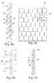
- the invention proposes a particular structure of a non-return plate, illustrated on the Figures 3a, 3b, 4a and 4b (for a first embodiment) and 5a, 5b, 6a and 6b (for a second embodiment).
- the basic principle consists in using a monoblock sheet 32 made of a flexible material, for example made of silicone, of small thickness (typically of the order of 1/3 mm), which will be arranged against the air extraction face, that is to say against the battery of fans 14 on the external side (as illustrated Figure 2 ).
- a monoblock sheet 32 made of a flexible material, for example made of silicone, of small thickness (typically of the order of 1/3 mm), which will be arranged against the air extraction face, that is to say against the battery of fans 14 on the external side (as illustrated Figure 2 ).
- the backing plate upstream side that is to say between the air inlet of the system and the air inlet of the fans.
- the one-piece sheet 32 comprises a two-dimensional network of elementary flaps 34 in the form of scales or tiles of very small dimensions (a few millimeters to a few centimeters on the side, this dimension in front of be significantly lower than that of a fan).
- Each of these flaps is constituted by a small thin and flat blade, juxtaposed with the others, and defined by a notch of the sheet of flexible material, this notch may be from molding, cut, stamped, etc.
- Each flap is defined by an outline 36, for example formed on the three sides of a square as in the examples illustrated, with a fourth side 38 of the side which is not cut and thus forms a material bridge connecting the surface of the square. flap to the remainder of the sheet 32 with possibility of deformation, this material bridge 38 acting in the manner of a hinge.
- Each flap 34 can thus be deformed, under the effect of a pressure gradient applied between the inner side 28 and the outer side 30 of the sheet, between an open position (illustrated Figures 4a and 6a ) releasing an air passage 40 between inner side 28 and outer side 30, and a closed position (illustrated Figures 4b and 6b ) where the flap is not curved, or less curved than in the open position, and where its free edge 42 comes into contact with the remainder of the sheet 32, thus obscuring the passage of air 40.
- the length l 1 of the free part of the flaps is greater than the corresponding dimension 1 2 of the opening of the sheet 32, which can be obtained by producing the sheet 32 with the illustrated configuration Figure 3a directly molded, that is to say with elementary flaps 34 molded so as to form in the free state an angle ⁇ relative to the plane of the remainder of the sheet.
- the resulting molded sheet is therefore, in the absence of external stress, in the illustrated form Figures 3a , with an overall dimension e less than 3 mm for a sheet thickness x of the order of 1/3 mm.
- the flaps 34 are defined by a stamping of the sheet 32, and their length is therefore the same as that of the corresponding opening of the sheet.
- the cut sheet 32 is in this case associated with a rigid against-sheet 46 comprising openings 48 each of dimension slightly smaller than the air passage 40, so as to leave along all or part of the contour 36 of the shutter a surface stop 52 against which will support the free edge 50 of the flap 34 in the presence of a back pressure between the outer side 30 and the inner side 28 (this situation is illustrated Figure 6b ).
Abstract
Le châssis (10) comprend une batterie de ventilateurs (16a, 16b, 16c, 16d) juxtaposés, avec une plaque antiretour (26) comprenant une feuille monobloc en matériau souple configurée en un réseau bidimensionnel de volets élémentaires déformables, non articulés, définis chacun par une entaille de la feuille de matériau souple le long d'un contour non fermé. Chaque volet est déformable entre une position ouvrante, où la plaque antiretour laisse passer le flux d'air, et une position obturante où le volet occulte le passage d'air et bloque tout flux d'air entre le côté interne et le côté externe du châssis sous l'effet d'une contre-pression côté externe.The frame (10) comprises a battery of fans (16a, 16b, 16c, 16d) juxtaposed with a non-return plate (26) comprising a one-piece sheet of flexible material configured as a two-dimensional network of deformable, non-articulated elementary flaps, each defined by a notch of the sheet of flexible material along an unclosed contour. Each flap is deformable between an open position, where the non-return plate allows the flow of air to pass, and a closed position where the flap conceals the air passage and blocks any flow of air between the inner side and the outer side of the flap. chassis under the effect of a counter pressure on the external side.
Description
L'invention concerne les équipements de réseau modulaires, en particulier les équipements tels que ceux utilisés dans les installations à grande échelle telles que grappes de serveurs, réseaux de télécommunications, routeurs... mises en oeuvre par les hébergeurs web, les fournisseurs d'accès Internet, les centres de stockage et de traitement de données de type datacenter, etc.The invention relates to modular network equipment, in particular equipment such as those used in large-scale installations such as server clusters, telecommunication networks, routers ... implemented by web hosts, providers of Internet access, datacenter data storage and processing centers, etc.
Ces équipements modulaires se présentent souvent sous la forme de châssis installés dans des baies, chaque châssis pouvant comporter un grand nombre d'équipements (serveurs, commutateurs ou switches, multiplexeurs de type DSLAM, unités de stockage de masse, etc.) très densément logés dans le châssis.This modular equipment is often in the form of chassis installed in bays, each chassis may include a large number of equipment (servers, switches or switches, DSLAM multiplexers, mass storage units, etc.) very densely housed. in the chassis.
La chaleur dégagée par ces équipements doit être évacuée en permanence par des moyens de ventilation puissants, de manière à éviter toute montée en température excessive. La ventilation de ces installations est un aspect particulièrement important pour garantir en toutes circonstances le bon fonctionnement des équipements et donc la continuité du service rendu aux clients et utilisateurs.The heat released by these devices must be evacuated permanently by powerful ventilation means, so as to avoid any excessive temperature rise. The ventilation of these installations is a particularly important aspect to ensure in all circumstances the proper functioning of the equipment and thus the continuity of the service provided to customers and users.
Les
Les deux contraintes majeures à respecter pour ces systèmes sont le débit d'extraction d'air, qui doit être très élevé, et la compacité mécanique, car l'emprise du système de ventilation sur le volume utile du châssis doit être la plus faible possible.The two major constraints to be respected for these systems are the air extraction rate, which must be very high, and the mechanical compactness, because the influence of the ventilation system on the useful volume of the chassis must be as low as possible .
Pour ce faire, les systèmes de ventilation comprennent généralement des batteries de ventilateurs, notamment à flux axial, opérant en parallèle, ces ventilateurs étant juxtaposés pour constituer un panneau plat d'extraction d'air comportant par exemple trois ou quatre ventilateurs montés côte à côte, ou un réseau bidimensionnel de 3 x 3 ou 4 x 4 ventilateurs. Ce panneau d'extraction d'air peut même se présenter sous forme d'un tiroir extractible ou fan rack inséré dans un emplacement correspondant du châssis.To do this, the ventilation systems generally comprise fan batteries, including axial flow, operating in parallel, these fans being juxtaposed to form a flat panel of air extraction comprising for example three or four fans mounted side by side , or a two-dimensional network of 3 x 3 or 4 x 4 fans. This air extraction panel can even be in the form of a pull-out drawer or fan rack inserted in a corresponding location of the frame.
La multiplication des ventilateurs permet d'assurer le débit d'extraction d'air voulu en respectant les contraintes de compacité du fait de la faible épaisseur du panneau, mais cette solution devient un point faible en cas de panne d'un des ventilateurs de la batterie de ventilateurs.The multiplication of the fans makes it possible to ensure the required air extraction rate while respecting the constraints of compactness because of the low thickness of the panel, but this solution becomes a weak point in case of failure of one of the fans of the battery of fans.
En effet, non seulement le ventilateur en panne n'extrait plus d'air du volume intérieur du châssis (ce qui réduit proportionnellement le débit d'air utile), mais en outre et surtout il devient une entrée d'air pour les ventilateurs voisins en fonctionnement, de sorte que ces derniers vont en fait brasser un important flux d'air (froid) entrant par l'ouverture du ventilateur en panne, en n'aspirant plus qu'une partie du volume d'air (chaud) du volume intérieur du châssis qu'ils aspiraient auparavant. Ainsi, non seulement le flux aspiré sera globalement moindre (du fait de la panne de l'un des ventilateurs), mais le ventilateur défaillant, par effet de boucle, va perturber le fonctionnement des autres ventilateurs, pour lesquels l'extraction d'air chaud deviendra bien moins efficace.In fact, not only does the exhausted fan extract more air from the interior of the chassis (which proportionally reduces the useful air flow), but more importantly it becomes an air inlet for the neighboring fans. in operation, so that they will actually brew a large flow of air (cold) entering the opening of the fan down, by sucking only a portion of the volume of air (hot) volume inside of the chassis that they aspired before. Thus, not only will the flow sucked be overall less (because of the failure of one of the fans), but the faulty fan, by loop effect, will disrupt the operation of the other fans, for which the extraction of air hot will become much less effective.
Ce phénomène devient particulièrement critique dans une configuration à deux ventilateurs, car dans ce cas la majeure partie de l'air aspiré par le ventilateur resté fonctionnel sera de l'air aspiré depuis l'ouverture du ventilateur voisin en panne. Le flux d'air chaud réellement extrait du volume intérieur du châssis sera alors très faible, et la température des circuits va vite monter et atteindre les seuils de sécurité.This phenomenon becomes particularly critical in a configuration with two fans, because in this case most of the air drawn by the fan remained functional air will be sucked from the opening of the nearby fan failed. The flow of hot air actually extracted from the interior volume of the chassis will then be very low, and the temperature of the circuits will quickly rise and reach the safety thresholds.
Les équipements sont bien entendu pourvus de système de surveillance permettant de détecter ces températures excessives, d'alerter un opérateur et d'arrêter ou ralentir le fonctionnement des circuits dans l'attente d'une intervention - mais entretemps le fonctionnement de l'équipement aura dû être interrompu ou fortement dégradé.The equipment is of course equipped with a monitoring system to detect these excessive temperatures, to alert an operator and to stop or slow the operation of the circuits while waiting for an intervention - but in the meantime the operation of the equipment will have had to be interrupted or severely degraded.
L'un des buts de l'invention est de remédier à cette difficulté, en proposant un moyen d'empêcher un ventilateur en panne dans une batterie de ventilateurs de perturber le fonctionnement des ventilateurs voisins, de manière que ces derniers continuent à fournir leur plein débit d'extraction d'air chaud, sans fuite d'entrée d'air dans le châssis à ventiler. Concrètement, comme les batteries de ventilateurs sont habituellement dimensionnées avec une marge de sécurité importante par rapport aux besoins réels en régime permanent, la défaillance d'un seul ventilateur ne devrait pas empêcher l'équipement de continuer à fonctionner normalement, permettant ainsi d'assurer la continuité du service jusqu'à l'intervention d'un opérateur pour l'échange du ventilateur défaillant.One of the aims of the invention is to remedy this difficulty, by proposing a means of preventing a fan that has failed in a battery of fans from disturbing the operation of the neighboring fans, so that they continue to supply their full capacity. hot air extraction rate, without air inlet leakage in the chassis to be ventilated. Specifically, since fan banks are usually dimensioned with a large margin of safety compared to actual steady-state requirements, the failure of a single fan should not prevent the equipment from continuing to operate normally, thus ensuring continuity of service until the intervention of an operator for the exchange of the faulty fan.
On verra également que la solution proposée par l'invention est parfaitement compatible avec les impératifs de compacité du système de ventilation, grâce à une très faible emprise additionnelle, et au surplus une très grande simplicité sur le plan mécanique, ne risquant pas de grever les coûts de fabrication du système de ventilation.It will also be seen that the solution proposed by the invention is perfectly compatible with the requirements of compactness of the ventilation system, thanks to a very low additional footprint, and in addition a very great simplicity on the mechanical level, not risking to burden the manufacturing costs of the ventilation system.
Plus précisément, l'invention propose un châssis d'équipement informatique, d'un type général connu tel que divulgué par le
La partie caractérisante de la revendication 1 expose les éléments spécifiques à l'invention. Les sous-revendications visent des modes de réalisation particuliers.The characterizing part of
On va maintenant décrire des exemples de mise en oeuvre de l'invention, en référence aux dessins annexés où les mêmes références désignent d'une figure à l'autre des éléments identiques ou fonctionnellement semblables.
- Les
Figures 1 a et 1 b sont des représentations schématiques, vues de dessus, illustrant le flux d'air dans un châssis pourvu d'une batterie de ventilateurs d'extraction d'air, respectivement avec tous les ventilateurs en fonctionnement normal et avec l'un des ventilateurs en panne. - La
Figure 2 illustre le placement de la plaque antiretour selon l'invention par rapport à une batterie de ventilateurs telle que celle de laFigure 1a . - Les
Figures 3a et 3b sont des vues, respectivement de côté et de face d'une plaque antiretour selon un premier mode de réalisation de l'invention. - Les
Figures 4a et 4b sont des vues de détail illustrant le fonctionnement de la plaque antiretour desFigures 3a et 3b , respectivement en position ouvrante et en position obturante. - Les
Figures 5a et 5b sont des vues, respectivement de côté et de face d'une plaque antiretour selon un second mode de réalisation de l'invention. - Les
Figures 6a et 6b sont des vues de détail illustrant le fonctionnement de la plaque antiretour desFigures 5a et 5b , respectivement en position ouvrante et en position obturante.
- The
Figures 1 a and 1b are diagrammatic views, seen from above, illustrating the flow of air in a frame provided with a battery of exhaust fans, respectively with all the fans in normal operation and with one of the fans broken down. - The
Figure 2 illustrates the placement of the non-return plate according to the invention with respect to a battery of fans such as that of theFigure 1a . - The
Figures 3a and 3b are views, respectively of side and front of a non-return plate according to a first embodiment of the invention. - The
Figures 4a and 4b are detailed views illustrating the operation of the anti-rollback plateFigures 3a and 3b respectively in the open position and in the closed position. - The
Figures 5a and 5b are views, respectively of side and front of a non-return plate according to a second embodiment of the invention. - The
Figures 6a and 6b are detailed views illustrating the operation of the anti-rollback plateFigures 5a and 5b respectively in the open position and in the closed position.
Sur les figures, la référence 10 désigne de façon générale un châssis ou boitier enfermant un équipement électronique 12, par exemple un commutateur ou switch, un multiplexeur DSLAM, etc. Les circuits de cet équipement dégagent en fonctionnement une quantité de chaleur importante, qu'il convient d'évacuer pour maintenir les circuits à une température de fonctionnement satisfaisante et éviter l'apparition de points chauds susceptibles de détériorer les circuits ou de déclencher une alarme conduisant à une interruption de fonctionnement de l'appareil.In the figures, the
Pour ce faire, l'une des faces du boitier 10 est pourvue d'une batterie 14 de ventilateurs, par exemple une pluralité de ventilateurs à flux axial 16a, 16b, 16c, 16d ... juxtaposés côte à côte pour former une rangée ou un panneau bidimensionnel de grande dimension, constituant une face d'extraction d'air du boitier. Sur une autre face du boitier sont disposées des entrées d'air 18 de sorte que, en fonctionnement normal (comme illustré sur la
La configuration en batterie de ventilateurs individuels alignés ou disposés en un réseau permet d'effectuer l'extraction d'air sur une large surface de l'un des côtés du boitier 10, tout en conservant une compacité importante du fait de la faible épaisseur de chacun des ventilateurs individuels, pour un flux d'air extrait globalement équivalent.The battery configuration of individual fans aligned or arranged in a network makes it possible to perform the extraction of air over a large surface of one of the sides of the
Cette configuration présente cependant un inconvénient, illustré Figure 1 b : si l'un des ventilateurs tombe en panne, par exemple le ventilateur 16b, celui-ci, bien entendu, ne va plus extraire d'air depuis l'intérieur du boitier, mais va de plus se comporter comme une entrée d'air de sorte que les ventilateurs voisins 16a et 16c vont, pour une grande partie, aspirer de l'air extérieur via l'ouverture du ventilateur 16b en panne (flèches 20, 22) au lieu d'extraire de l'air chaud depuis le volume intérieur du boitier.This configuration however has a disadvantage, illustrated in Figure 1b: if one of the fans fails, for example the
Ainsi, l'efficacité de la ventilation sera non seulement amoindrie par la panne de l'un des ventilateurs, mais également dégradée pour les ventilateurs restant en fonctionnement, de sorte que globalement la ventilation devient largement moins efficace, avec le risque de création d'une zone chaude 24 du circuit 12, pouvant conduire à une alarme de température et donc une interruption du fonctionnement de l'équipement.Thus, the efficiency of ventilation will be not only reduced by the failure of one of the fans, but also degraded for fans remaining in operation, so that overall ventilation becomes largely less efficient, with the risk of creating a
Pour pallier cet inconvénient, l'invention propose, comme illustré
Les clapets antiretour traditionnels sont souvent constitués d'une mécanique complexe de volets basculants montés sur un axe, qui s'ouvrent quand le flux d'air les pousse et se ferment par gravité, par ressort ou simplement par inversion du flux d'air. Ces clapets antiretour conventionnels sont constitués de nombreuses pièces complexes et nécessitent un assemblage mécanique long et minutieux. Ils présentent en outre un encombrement physique non négligeable en épaisseur en particulier, qui empêche de les utiliser dans des systèmes très compacts comme les châssis d'équipements électroniques.Traditional check valves are often made up of a complex mechanism of axially mounted tilting flaps, which open when the airflow pushes them and close by gravity, spring or simply by reversing the flow of air. These conventional check valves are made of many complex parts and require a long and careful mechanical assembly. They also have a significant physical size in thickness in particular, which prevents them from using in very compact systems such as electronic equipment chassis.
Pour pallier cet inconvénient, l'invention propose une structure particulière de plaque antiretour, illustrée sur les
Le principe de base, commun à tous les modes de réalisation, consiste à utiliser une feuille monobloc 32 en un matériau souple, par exemple en silicone, de faible épaisseur (typiquement de l'ordre de 1/3 mm), qui sera disposée contre la face d'extraction d'air, c'est-à-dire contre la batterie de ventilateurs 14 côté externe (comme illustré
La feuille monobloc 32 comporte un réseau bidimensionnel de volets élémentaires 34 en forme d'écailles ou tuiles de très faible dimension (quelques millimètres à quelques centimètres de côté, cette dimension devant être notablement inférieure à celle d'un ventilateur). Chacun de ces volets est constitué par une petite lame mince et plate, juxtaposée avec les autres, et définie par une entaille de la feuille de matériau souple, cette entaille pouvant être venue de moulage, découpée, estampée, etc. Chaque volet est défini par un contour 36, par exemple formé sur les trois côtés d'un carré comme dans les exemples illustrés, avec un quatrième côté 38 du côté qui n'est pas entaillé et forme ainsi un pont de matière reliant la surface du volet au reste de la feuille 32 avec possibilité de déformation, ce pont de matière 38 agissant à la manière d'une charnière.The one-
Chaque volet 34 peut être ainsi déformé, sous l'effet d'un gradient de pression appliqué entre le côté interne 28 et le côté externe 30 de la feuille, entre une position ouvrante (illustrée
Dans le mode de réalisation des
En présence d'un gradient de pression dirigé du côté interne 28 vers le côté externe 30 (
Dans le second mode de réalisation, illustré
De façon générale, quels que soient les détails de réalisation, on constatera que la solution de l'invention présente une multiplicité d'avantages, notamment :
- très faible cout de réalisation ;
- silence de fonctionnement ;
- absence de risques de grippage, etc. (à la différence des clapets mécaniques articulés) ;
- possibilité de conditionnement en une feuille de grande dimension, découpable pour l'adapter aux différents panneaux de ventilateurs utilisés ;
- très faible encombrement en épaisseur ; et
- possibilité d'adjonction aisée à des systèmes déjà existants, dans la mesure où il n'est pas nécessaire de modifier le système de ventilation.
- very low cost of realization;
- silence of operation;
- no risk of seizure, etc. (unlike articulated mechanical valves);
- possibility of packaging in a sheet of large size, cutable to adapt it to the different panels of fans used;
- very small footprint in thickness; and
- easy addition to already existing systems, as it is not necessary to modify the ventilation system.
Claims (3)
le châssis comportant une plaque antiretour (26) disposée contre la face d'extraction d'air, cette plaque antiretour comprenant une feuille monobloc (32) en matériau souple configurée en un réseau bidimensionnel de volets élémentaires (34) déformables, non articulés, définis chacun par une entaille de la feuille de matériau souple le long d'un contour non fermé (36) laissant subsister entre le volet élémentaire et le reste de la feuille un pont de matière (38), le contour de la région entaillée définissant un passage d'air (40) et chaque volet élémentaire étant déformable entre :
la plaque antiretour laissant alors passer le flux d'air du côté interne vers le côté externe du châssis sous l'effet d'une surpression côté interne ; et
et en ce qu' en position obturante le contour (36) du volet élémentaire est en contact avec le contour homologue de la feuille, occultant ainsi le passage d'air formé par la région entaillée de la feuille.A chassis (10) of computer equipment, this chassis comprising an air extraction face adapted to receive a battery of fans (16a, 16b, 16c, 16d) juxtaposed, the fans being able to create an air flow unidirectional from an inner side (28) of the frame to an outer side (30) of the same frame,
the frame comprising a non-return plate (26) disposed against the air extraction face, this non-return plate comprising a one-piece sheet (32) of flexible material configured as a two-dimensional network of deformable, non-articulated, elementary flaps (34) defined each by a notch of the sheet of flexible material along an unclosed contour (36) leaving between the elementary component and the remainder of the sheet a material bridge (38), the contour of the notched region defining a passage of air (40) and each elementary component being deformable between:
the non-return plate then allowing the flow of air to flow from the internal side to the outer side of the chassis under the effect of an internal pressure; and
and in that in the closed position the contour (36) of the elementary flap is in contact with the homologous contour of the sheet, thereby obscuring the passage of air formed by the notched region of the sheet.
et dans lequel la plaque antiretour comprend en outre, côté interne, une contre-feuille (46) en matériau rigide avec des ouvertures (48) homologues des passages d'air de la feuille en matériau souple, ces ouvertures portant une butée (52) telle que le bord libre (50) du volet élémentaire en vis-à-vis de l'ouverture vienne en contact avec cette butée dans la position obturante du volet élémentaire.The frame of claim 1, wherein each individual flap (34) is, in the free state, coplanar with the remainder of the sheet (32), each individual flap having a length equal to the length of the homologous edge of the region notched in the leaf,
and wherein the backing plate further comprises, on the inner side, a backing sheet (46) of rigid material with openings (48) homologous to the air passages of the sheet of flexible material, these openings carrying a stop (52). such that the free edge (50) of the elementary shutter vis-à-vis the opening comes into contact with this stop in the closed position of the elementary shutter.
Applications Claiming Priority (1)
| Application Number | Priority Date | Filing Date | Title |
|---|---|---|---|
| FR1450386A FR3016708B1 (en) | 2014-01-17 | 2014-01-17 | VENTILATION SYSTEM FOR CHASSIS OF COMPUTER EQUIPMENT |
Publications (2)
| Publication Number | Publication Date |
|---|---|
| EP2897448A1 true EP2897448A1 (en) | 2015-07-22 |
| EP2897448B1 EP2897448B1 (en) | 2017-02-22 |
Family
ID=50780642
Family Applications (1)
| Application Number | Title | Priority Date | Filing Date |
|---|---|---|---|
| EP14197485.7A Active EP2897448B1 (en) | 2014-01-17 | 2014-12-11 | Ventilation system for computer chassis |
Country Status (3)
| Country | Link |
|---|---|
| EP (1) | EP2897448B1 (en) |
| ES (1) | ES2625834T3 (en) |
| FR (1) | FR3016708B1 (en) |
Cited By (1)
| Publication number | Priority date | Publication date | Assignee | Title |
|---|---|---|---|---|
| FR3135925A1 (en) * | 2022-05-31 | 2023-12-01 | Psa Automobiles Sa | COOLING DEVICE FOR THE BATTERY CHARGER OF ELECTRIC MOTOR VEHICLES |
Families Citing this family (1)
| Publication number | Priority date | Publication date | Assignee | Title |
|---|---|---|---|---|
| US11781555B2 (en) * | 2021-12-28 | 2023-10-10 | Quanta Computer Inc. | Fan guard configured to selectively cover aperture |
Citations (5)
| Publication number | Priority date | Publication date | Assignee | Title |
|---|---|---|---|---|
| US5890959A (en) | 1998-03-31 | 1999-04-06 | Digital Equipment Corporation | High efficiency blower system with integral backflow preventor |
| US6031717A (en) | 1999-04-13 | 2000-02-29 | Dell Usa, L.P. | Back flow limiting device for failed redundant parallel fan |
| US6135875A (en) | 1999-06-29 | 2000-10-24 | Emc Corporation | Electrical cabinet |
| US20060016482A1 (en) | 2004-07-22 | 2006-01-26 | International Business Machines Corporation | Device for preventing backflow in a cooling system |
| US20130065501A1 (en) | 2011-09-08 | 2013-03-14 | Inventec Corporation | Air vent and server rack |
-
2014
- 2014-01-17 FR FR1450386A patent/FR3016708B1/en not_active Expired - Fee Related
- 2014-12-11 ES ES14197485.7T patent/ES2625834T3/en active Active
- 2014-12-11 EP EP14197485.7A patent/EP2897448B1/en active Active
Patent Citations (5)
| Publication number | Priority date | Publication date | Assignee | Title |
|---|---|---|---|---|
| US5890959A (en) | 1998-03-31 | 1999-04-06 | Digital Equipment Corporation | High efficiency blower system with integral backflow preventor |
| US6031717A (en) | 1999-04-13 | 2000-02-29 | Dell Usa, L.P. | Back flow limiting device for failed redundant parallel fan |
| US6135875A (en) | 1999-06-29 | 2000-10-24 | Emc Corporation | Electrical cabinet |
| US20060016482A1 (en) | 2004-07-22 | 2006-01-26 | International Business Machines Corporation | Device for preventing backflow in a cooling system |
| US20130065501A1 (en) | 2011-09-08 | 2013-03-14 | Inventec Corporation | Air vent and server rack |
Cited By (1)
| Publication number | Priority date | Publication date | Assignee | Title |
|---|---|---|---|---|
| FR3135925A1 (en) * | 2022-05-31 | 2023-12-01 | Psa Automobiles Sa | COOLING DEVICE FOR THE BATTERY CHARGER OF ELECTRIC MOTOR VEHICLES |
Also Published As
| Publication number | Publication date |
|---|---|
| FR3016708A1 (en) | 2015-07-24 |
| FR3016708B1 (en) | 2017-05-19 |
| EP2897448B1 (en) | 2017-02-22 |
| ES2625834T3 (en) | 2017-07-20 |
Similar Documents
| Publication | Publication Date | Title |
|---|---|---|
| EP2420117B1 (en) | Housing for onboard electronics | |
| EP3664234A1 (en) | Ventilation unit for an electrical cabinet | |
| EP2897448B1 (en) | Ventilation system for computer chassis | |
| EP2770810A1 (en) | Electronic card provided with a liquid cooling system | |
| EP3130046A1 (en) | Electrical cabinet intended for uses in hazardous environments | |
| CA2991551A1 (en) | Card reader body with secure memory | |
| US11817566B2 (en) | Battery fire suppressant system | |
| EP2715480B1 (en) | Container equipped for a technical infrastructure | |
| EP2256885B1 (en) | Device for limiting the excess pressure inside a compartment belonging to an electrical device | |
| EP1937048B1 (en) | Device with integrated electronic components equipped with a partition for separating ventilated areas | |
| EP2638789A2 (en) | Display screen | |
| FR3089703A1 (en) | Air flow management system adaptable to an electrical cabinet | |
| JP2002006994A (en) | Cooling unit | |
| EP3096260B1 (en) | Secure compact keyboard | |
| EP1644909A2 (en) | Dynamic display system with interchangeable removable digital screens with posters in a backlighted housing | |
| CA2753353A1 (en) | Protective device for an electronic system mounted in a rack | |
| EP3675616B1 (en) | System for protecting an electronic component | |
| FR3030181A1 (en) | BOX OF ELECTRONIC EQUIPMENT ON BOARD AND CALCULATOR AVIONIQUE COMPRISING SUCH A BOX | |
| EP3647188A1 (en) | Heat shield for a braked aircraft wheel | |
| EP3840558B1 (en) | Cooling module for an electrical cabinet | |
| FR2997570A1 (en) | SECURE MEMORY CARD CONNECTOR. | |
| FR2864421A1 (en) | Ventilating system for cooling apparatus of electrical or electronic apparatus, has case defining two partitioned cavities that are connected to respective primary and secondary sources and are separated by continuous partition | |
| FR2848310A3 (en) | COMBINATION STRUCTURE OF A THERMAL DISSIPATION APPARATUS OF A CENTRAL UNIT AND A POWER SUPPLY | |
| WO2016166137A1 (en) | Electronic apparatus | |
| FR3134495A1 (en) | Cooling module for computer hardware |
Legal Events
| Date | Code | Title | Description |
|---|---|---|---|
| PUAI | Public reference made under article 153(3) epc to a published international application that has entered the european phase |
Free format text: ORIGINAL CODE: 0009012 |
|
| 17P | Request for examination filed |
Effective date: 20141211 |
|
| AK | Designated contracting states |
Kind code of ref document: A1 Designated state(s): AL AT BE BG CH CY CZ DE DK EE ES FI FR GB GR HR HU IE IS IT LI LT LU LV MC MK MT NL NO PL PT RO RS SE SI SK SM TR |
|
| AX | Request for extension of the european patent |
Extension state: BA ME |
|
| 17P | Request for examination filed |
Effective date: 20150722 |
|
| RBV | Designated contracting states (corrected) |
Designated state(s): AL AT BE BG CH CY CZ DE DK EE ES FI FR GB GR HR HU IE IS IT LI LT LU LV MC MK MT NL NO PL PT RO RS SE SI SK SM TR |
|
| GRAP | Despatch of communication of intention to grant a patent |
Free format text: ORIGINAL CODE: EPIDOSNIGR1 |
|
| INTG | Intention to grant announced |
Effective date: 20161103 |
|
| GRAS | Grant fee paid |
Free format text: ORIGINAL CODE: EPIDOSNIGR3 |
|
| GRAA | (expected) grant |
Free format text: ORIGINAL CODE: 0009210 |
|
| AK | Designated contracting states |
Kind code of ref document: B1 Designated state(s): AL AT BE BG CH CY CZ DE DK EE ES FI FR GB GR HR HU IE IS IT LI LT LU LV MC MK MT NL NO PL PT RO RS SE SI SK SM TR |
|
| REG | Reference to a national code |
Ref country code: GB Ref legal event code: FG4D Free format text: NOT ENGLISH |
|
| REG | Reference to a national code |
Ref country code: CH Ref legal event code: EP |
|
| REG | Reference to a national code |
Ref country code: AT Ref legal event code: REF Ref document number: 870181 Country of ref document: AT Kind code of ref document: T Effective date: 20170315 |
|
| REG | Reference to a national code |
Ref country code: IE Ref legal event code: FG4D Free format text: LANGUAGE OF EP DOCUMENT: FRENCH |
|
| REG | Reference to a national code |
Ref country code: DE Ref legal event code: R096 Ref document number: 602014006889 Country of ref document: DE |
|
| REG | Reference to a national code |
Ref country code: NL Ref legal event code: FP |
|
| REG | Reference to a national code |
Ref country code: LT Ref legal event code: MG4D |
|
| REG | Reference to a national code |
Ref country code: AT Ref legal event code: MK05 Ref document number: 870181 Country of ref document: AT Kind code of ref document: T Effective date: 20170222 |
|
| REG | Reference to a national code |
Ref country code: ES Ref legal event code: FG2A Ref document number: 2625834 Country of ref document: ES Kind code of ref document: T3 Effective date: 20170720 |
|
| PG25 | Lapsed in a contracting state [announced via postgrant information from national office to epo] |
Ref country code: GR Free format text: LAPSE BECAUSE OF FAILURE TO SUBMIT A TRANSLATION OF THE DESCRIPTION OR TO PAY THE FEE WITHIN THE PRESCRIBED TIME-LIMIT Effective date: 20170523 Ref country code: NO Free format text: LAPSE BECAUSE OF FAILURE TO SUBMIT A TRANSLATION OF THE DESCRIPTION OR TO PAY THE FEE WITHIN THE PRESCRIBED TIME-LIMIT Effective date: 20170522 Ref country code: HR Free format text: LAPSE BECAUSE OF FAILURE TO SUBMIT A TRANSLATION OF THE DESCRIPTION OR TO PAY THE FEE WITHIN THE PRESCRIBED TIME-LIMIT Effective date: 20170222 Ref country code: FI Free format text: LAPSE BECAUSE OF FAILURE TO SUBMIT A TRANSLATION OF THE DESCRIPTION OR TO PAY THE FEE WITHIN THE PRESCRIBED TIME-LIMIT Effective date: 20170222 Ref country code: LT Free format text: LAPSE BECAUSE OF FAILURE TO SUBMIT A TRANSLATION OF THE DESCRIPTION OR TO PAY THE FEE WITHIN THE PRESCRIBED TIME-LIMIT Effective date: 20170222 |
|
| PG25 | Lapsed in a contracting state [announced via postgrant information from national office to epo] |
Ref country code: LV Free format text: LAPSE BECAUSE OF FAILURE TO SUBMIT A TRANSLATION OF THE DESCRIPTION OR TO PAY THE FEE WITHIN THE PRESCRIBED TIME-LIMIT Effective date: 20170222 Ref country code: PT Free format text: LAPSE BECAUSE OF FAILURE TO SUBMIT A TRANSLATION OF THE DESCRIPTION OR TO PAY THE FEE WITHIN THE PRESCRIBED TIME-LIMIT Effective date: 20170622 Ref country code: SE Free format text: LAPSE BECAUSE OF FAILURE TO SUBMIT A TRANSLATION OF THE DESCRIPTION OR TO PAY THE FEE WITHIN THE PRESCRIBED TIME-LIMIT Effective date: 20170222 Ref country code: RS Free format text: LAPSE BECAUSE OF FAILURE TO SUBMIT A TRANSLATION OF THE DESCRIPTION OR TO PAY THE FEE WITHIN THE PRESCRIBED TIME-LIMIT Effective date: 20170222 Ref country code: BG Free format text: LAPSE BECAUSE OF FAILURE TO SUBMIT A TRANSLATION OF THE DESCRIPTION OR TO PAY THE FEE WITHIN THE PRESCRIBED TIME-LIMIT Effective date: 20170522 Ref country code: AT Free format text: LAPSE BECAUSE OF FAILURE TO SUBMIT A TRANSLATION OF THE DESCRIPTION OR TO PAY THE FEE WITHIN THE PRESCRIBED TIME-LIMIT Effective date: 20170222 |
|
| PG25 | Lapsed in a contracting state [announced via postgrant information from national office to epo] |
Ref country code: CZ Free format text: LAPSE BECAUSE OF FAILURE TO SUBMIT A TRANSLATION OF THE DESCRIPTION OR TO PAY THE FEE WITHIN THE PRESCRIBED TIME-LIMIT Effective date: 20170222 Ref country code: SK Free format text: LAPSE BECAUSE OF FAILURE TO SUBMIT A TRANSLATION OF THE DESCRIPTION OR TO PAY THE FEE WITHIN THE PRESCRIBED TIME-LIMIT Effective date: 20170222 Ref country code: EE Free format text: LAPSE BECAUSE OF FAILURE TO SUBMIT A TRANSLATION OF THE DESCRIPTION OR TO PAY THE FEE WITHIN THE PRESCRIBED TIME-LIMIT Effective date: 20170222 Ref country code: RO Free format text: LAPSE BECAUSE OF FAILURE TO SUBMIT A TRANSLATION OF THE DESCRIPTION OR TO PAY THE FEE WITHIN THE PRESCRIBED TIME-LIMIT Effective date: 20170222 |
|
| REG | Reference to a national code |
Ref country code: DE Ref legal event code: R097 Ref document number: 602014006889 Country of ref document: DE |
|
| PG25 | Lapsed in a contracting state [announced via postgrant information from national office to epo] |
Ref country code: DK Free format text: LAPSE BECAUSE OF FAILURE TO SUBMIT A TRANSLATION OF THE DESCRIPTION OR TO PAY THE FEE WITHIN THE PRESCRIBED TIME-LIMIT Effective date: 20170222 Ref country code: SM Free format text: LAPSE BECAUSE OF FAILURE TO SUBMIT A TRANSLATION OF THE DESCRIPTION OR TO PAY THE FEE WITHIN THE PRESCRIBED TIME-LIMIT Effective date: 20170222 Ref country code: PL Free format text: LAPSE BECAUSE OF FAILURE TO SUBMIT A TRANSLATION OF THE DESCRIPTION OR TO PAY THE FEE WITHIN THE PRESCRIBED TIME-LIMIT Effective date: 20170222 |
|
| REG | Reference to a national code |
Ref country code: FR Ref legal event code: PLFP Year of fee payment: 4 |
|
| PLBE | No opposition filed within time limit |
Free format text: ORIGINAL CODE: 0009261 |
|
| STAA | Information on the status of an ep patent application or granted ep patent |
Free format text: STATUS: NO OPPOSITION FILED WITHIN TIME LIMIT |
|
| 26N | No opposition filed |
Effective date: 20171123 |
|
| PG25 | Lapsed in a contracting state [announced via postgrant information from national office to epo] |
Ref country code: SI Free format text: LAPSE BECAUSE OF FAILURE TO SUBMIT A TRANSLATION OF THE DESCRIPTION OR TO PAY THE FEE WITHIN THE PRESCRIBED TIME-LIMIT Effective date: 20170222 |
|
| REG | Reference to a national code |
Ref country code: IE Ref legal event code: MM4A |
|
| PG25 | Lapsed in a contracting state [announced via postgrant information from national office to epo] |
Ref country code: LU Free format text: LAPSE BECAUSE OF NON-PAYMENT OF DUE FEES Effective date: 20171211 Ref country code: MT Free format text: LAPSE BECAUSE OF FAILURE TO SUBMIT A TRANSLATION OF THE DESCRIPTION OR TO PAY THE FEE WITHIN THE PRESCRIBED TIME-LIMIT Effective date: 20170222 |
|
| PG25 | Lapsed in a contracting state [announced via postgrant information from national office to epo] |
Ref country code: IE Free format text: LAPSE BECAUSE OF NON-PAYMENT OF DUE FEES Effective date: 20171211 |
|
| PG25 | Lapsed in a contracting state [announced via postgrant information from national office to epo] |
Ref country code: MC Free format text: LAPSE BECAUSE OF FAILURE TO SUBMIT A TRANSLATION OF THE DESCRIPTION OR TO PAY THE FEE WITHIN THE PRESCRIBED TIME-LIMIT Effective date: 20170222 Ref country code: HU Free format text: LAPSE BECAUSE OF FAILURE TO SUBMIT A TRANSLATION OF THE DESCRIPTION OR TO PAY THE FEE WITHIN THE PRESCRIBED TIME-LIMIT; INVALID AB INITIO Effective date: 20141211 |
|
| PG25 | Lapsed in a contracting state [announced via postgrant information from national office to epo] |
Ref country code: CY Free format text: LAPSE BECAUSE OF FAILURE TO SUBMIT A TRANSLATION OF THE DESCRIPTION OR TO PAY THE FEE WITHIN THE PRESCRIBED TIME-LIMIT Effective date: 20170222 |
|
| PG25 | Lapsed in a contracting state [announced via postgrant information from national office to epo] |
Ref country code: MK Free format text: LAPSE BECAUSE OF FAILURE TO SUBMIT A TRANSLATION OF THE DESCRIPTION OR TO PAY THE FEE WITHIN THE PRESCRIBED TIME-LIMIT Effective date: 20170222 |
|
| PG25 | Lapsed in a contracting state [announced via postgrant information from national office to epo] |
Ref country code: TR Free format text: LAPSE BECAUSE OF FAILURE TO SUBMIT A TRANSLATION OF THE DESCRIPTION OR TO PAY THE FEE WITHIN THE PRESCRIBED TIME-LIMIT Effective date: 20170222 |
|
| PG25 | Lapsed in a contracting state [announced via postgrant information from national office to epo] |
Ref country code: AL Free format text: LAPSE BECAUSE OF FAILURE TO SUBMIT A TRANSLATION OF THE DESCRIPTION OR TO PAY THE FEE WITHIN THE PRESCRIBED TIME-LIMIT Effective date: 20170222 Ref country code: IS Free format text: LAPSE BECAUSE OF FAILURE TO SUBMIT A TRANSLATION OF THE DESCRIPTION OR TO PAY THE FEE WITHIN THE PRESCRIBED TIME-LIMIT Effective date: 20170622 |
|
| PGFP | Annual fee paid to national office [announced via postgrant information from national office to epo] |
Ref country code: BE Payment date: 20221220 Year of fee payment: 9 |
|
| PGFP | Annual fee paid to national office [announced via postgrant information from national office to epo] |
Ref country code: ES Payment date: 20230119 Year of fee payment: 9 Ref country code: CH Payment date: 20230103 Year of fee payment: 9 |
|
| PGFP | Annual fee paid to national office [announced via postgrant information from national office to epo] |
Ref country code: IT Payment date: 20221230 Year of fee payment: 9 |
|
| PGFP | Annual fee paid to national office [announced via postgrant information from national office to epo] |
Ref country code: GB Payment date: 20231220 Year of fee payment: 10 |
|
| PGFP | Annual fee paid to national office [announced via postgrant information from national office to epo] |
Ref country code: NL Payment date: 20231219 Year of fee payment: 10 Ref country code: FR Payment date: 20231211 Year of fee payment: 10 Ref country code: DE Payment date: 20231214 Year of fee payment: 10 |
|
| PGFP | Annual fee paid to national office [announced via postgrant information from national office to epo] |
Ref country code: BE Payment date: 20231218 Year of fee payment: 10 |