EP2889232B1 - Hinged closure device with first-opening indicator - Google Patents
Hinged closure device with first-opening indicator Download PDFInfo
- Publication number
- EP2889232B1 EP2889232B1 EP14199569.6A EP14199569A EP2889232B1 EP 2889232 B1 EP2889232 B1 EP 2889232B1 EP 14199569 A EP14199569 A EP 14199569A EP 2889232 B1 EP2889232 B1 EP 2889232B1
- Authority
- EP
- European Patent Office
- Prior art keywords
- opening
- cap
- closure device
- opening indicator
- hinge
- Prior art date
- Legal status (The legal status is an assumption and is not a legal conclusion. Google has not performed a legal analysis and makes no representation as to the accuracy of the status listed.)
- Not-in-force
Links
Images


Classifications
-
- B—PERFORMING OPERATIONS; TRANSPORTING
- B65—CONVEYING; PACKING; STORING; HANDLING THIN OR FILAMENTARY MATERIAL
- B65D—CONTAINERS FOR STORAGE OR TRANSPORT OF ARTICLES OR MATERIALS, e.g. BAGS, BARRELS, BOTTLES, BOXES, CANS, CARTONS, CRATES, DRUMS, JARS, TANKS, HOPPERS, FORWARDING CONTAINERS; ACCESSORIES, CLOSURES, OR FITTINGS THEREFOR; PACKAGING ELEMENTS; PACKAGES
- B65D43/00—Lids or covers for rigid or semi-rigid containers
- B65D43/02—Removable lids or covers
- B65D43/0235—Removable lids or covers with integral tamper element
- B65D43/0264—Removable lids or covers with integral tamper element secured only by friction or gravity before removal of the tamper element
- B65D43/0274—Removable lids or covers with integral tamper element secured only by friction or gravity before removal of the tamper element only on the outside, or a part turned to the outside, of the mouth of the container
-
- B—PERFORMING OPERATIONS; TRANSPORTING
- B65—CONVEYING; PACKING; STORING; HANDLING THIN OR FILAMENTARY MATERIAL
- B65D—CONTAINERS FOR STORAGE OR TRANSPORT OF ARTICLES OR MATERIALS, e.g. BAGS, BARRELS, BOTTLES, BOXES, CANS, CARTONS, CRATES, DRUMS, JARS, TANKS, HOPPERS, FORWARDING CONTAINERS; ACCESSORIES, CLOSURES, OR FITTINGS THEREFOR; PACKAGING ELEMENTS; PACKAGES
- B65D47/00—Closures with filling and discharging, or with discharging, devices
- B65D47/04—Closures with discharging devices other than pumps
- B65D47/06—Closures with discharging devices other than pumps with pouring spouts or tubes; with discharge nozzles or passages
- B65D47/08—Closures with discharging devices other than pumps with pouring spouts or tubes; with discharge nozzles or passages having articulated or hinged closures
- B65D47/0857—Closures with discharging devices other than pumps with pouring spouts or tubes; with discharge nozzles or passages having articulated or hinged closures made separately from the base element provided with the spout or discharge passage
-
- B—PERFORMING OPERATIONS; TRANSPORTING
- B65—CONVEYING; PACKING; STORING; HANDLING THIN OR FILAMENTARY MATERIAL
- B65D—CONTAINERS FOR STORAGE OR TRANSPORT OF ARTICLES OR MATERIALS, e.g. BAGS, BARRELS, BOTTLES, BOXES, CANS, CARTONS, CRATES, DRUMS, JARS, TANKS, HOPPERS, FORWARDING CONTAINERS; ACCESSORIES, CLOSURES, OR FITTINGS THEREFOR; PACKAGING ELEMENTS; PACKAGES
- B65D43/00—Lids or covers for rigid or semi-rigid containers
- B65D43/02—Removable lids or covers
- B65D43/0235—Removable lids or covers with integral tamper element
-
- B—PERFORMING OPERATIONS; TRANSPORTING
- B65—CONVEYING; PACKING; STORING; HANDLING THIN OR FILAMENTARY MATERIAL
- B65D—CONTAINERS FOR STORAGE OR TRANSPORT OF ARTICLES OR MATERIALS, e.g. BAGS, BARRELS, BOTTLES, BOXES, CANS, CARTONS, CRATES, DRUMS, JARS, TANKS, HOPPERS, FORWARDING CONTAINERS; ACCESSORIES, CLOSURES, OR FITTINGS THEREFOR; PACKAGING ELEMENTS; PACKAGES
- B65D43/00—Lids or covers for rigid or semi-rigid containers
- B65D43/14—Non-removable lids or covers
- B65D43/16—Non-removable lids or covers hinged for upward or downward movement
-
- B—PERFORMING OPERATIONS; TRANSPORTING
- B65—CONVEYING; PACKING; STORING; HANDLING THIN OR FILAMENTARY MATERIAL
- B65D—CONTAINERS FOR STORAGE OR TRANSPORT OF ARTICLES OR MATERIALS, e.g. BAGS, BARRELS, BOTTLES, BOXES, CANS, CARTONS, CRATES, DRUMS, JARS, TANKS, HOPPERS, FORWARDING CONTAINERS; ACCESSORIES, CLOSURES, OR FITTINGS THEREFOR; PACKAGING ELEMENTS; PACKAGES
- B65D47/00—Closures with filling and discharging, or with discharging, devices
- B65D47/04—Closures with discharging devices other than pumps
- B65D47/06—Closures with discharging devices other than pumps with pouring spouts or tubes; with discharge nozzles or passages
- B65D47/08—Closures with discharging devices other than pumps with pouring spouts or tubes; with discharge nozzles or passages having articulated or hinged closures
- B65D47/0857—Closures with discharging devices other than pumps with pouring spouts or tubes; with discharge nozzles or passages having articulated or hinged closures made separately from the base element provided with the spout or discharge passage
- B65D47/0861—Closures with discharging devices other than pumps with pouring spouts or tubes; with discharge nozzles or passages having articulated or hinged closures made separately from the base element provided with the spout or discharge passage and elastically biased towards both the open and the closed positions
-
- B—PERFORMING OPERATIONS; TRANSPORTING
- B65—CONVEYING; PACKING; STORING; HANDLING THIN OR FILAMENTARY MATERIAL
- B65D—CONTAINERS FOR STORAGE OR TRANSPORT OF ARTICLES OR MATERIALS, e.g. BAGS, BARRELS, BOTTLES, BOXES, CANS, CARTONS, CRATES, DRUMS, JARS, TANKS, HOPPERS, FORWARDING CONTAINERS; ACCESSORIES, CLOSURES, OR FITTINGS THEREFOR; PACKAGING ELEMENTS; PACKAGES
- B65D2401/00—Tamper-indicating means
- B65D2401/15—Tearable part of the closure
Definitions
- the invention relates to a closure device, according to the preamble of claim 1, at least two parts, comprising a base having a function of attachment to a container neck and / or a pourer function, and a cap hinged to this base.
- Knuckles are known in one, two or three plastic parts, commonly called sports caps, allowing a consumer to directly drink the contents of a container and close it.
- WO 2004/007313 is illustrated a plug of this type made in two parts, with a first piece constituting both a mounting base on a container neck and a pourer allowing a plug in the mouth, and a second piece forming a cap to cover and seal the pourer, the second piece further comprising a fixing ring and a flexible hinge strap connecting the fastening ring to the cap.
- An advantage of this type of cap is that it can be manufactured in closed position, that is to say without closing operation by pivoting the cap on its joint, the assembly of the two parts being made by a simple movement of translation, during which the ring is inserted by its lower part in a fixing groove provided for this purpose in the base.
- the ring is also provided in its upper part with one or more indentations each receiving a first opening indicator linked on the one hand to the bottom of the notch and on the other hand to a rim of the cap.
- the desired effect is to achieve, upon opening, a rupture of the first opening indicator in two parts, one connected to the cap and the other to the ring, and, by a displacement or a deformation of the at least one of these two parts, to make the opening detectable by the consumer.
- EP 1 892 194 has been proposed a sports cap in two parts, namely a first part forming a base and a cap hinged to the base by a hinge, and a second piece constituting a pourer inserted into the base.
- This plug can also be manufactured in closed position, by axial assembly of the two parts.
- An annular dead volume is preserved between the two assembled parts, which volume is used to house, after opening, a first opening indicator which separates from a peripheral wall of the cap.
- the disappearance of the first opening witness does not necessarily allow a consumer unfamiliar with the plug in question, to visually recognize if it has already been opened.
- the fact that the base and the cap belong to the same room limits the variations in color and material for the visible portion externally, except to manufacture this piece by bi-injection, which increases the cost.
- a plug comprising a first piece and a second piece, rigidly associated with each other.
- the first piece forms a peripheral base and a pouring means. It also includes first peripheral attachment means for the second part.
- the second part forms a cover, means for pivoting the cover and second peripheral means of attachment complementary to the first attachment means, these second means being constituted by a ring.
- the cap thus comprises two parts, one that can be described as fixed - in that it is fixed rigidly on the neck of the container - and the other that can be described as mobile, associated with the to one another by the pivoting means.
- the fixed part comprises the first part and the ring, while the movable part is formed of the only cover.
- the cap also comprises external means ensuring the inviolability before a first opening, interposed between the fixed part and the movable part.
- These means are made in the form of frangible bridges, connecting a lower free edge of the bonnet skirt to an adjacent upper edge of the ring.
- Frangible bridges are designed to be broken when, when the hood is first opened, the user pulls axially up on the hood opposite the pivoting means.
- the frangible bridges can be replaced by a line or a zone of lower resistance.
- the change of state of the inviolability means is not very visible when the cover, after first opening, is brought back to the closed position. The consumer must therefore rely on the resistance of the cap before the first opening to detect the condition of the cap.
- the invention aims to remedy all or part of the disadvantages of the state of the art identified above.
- a closure device to be secured to a container neck, the closure device comprising: a first piece forming a base for attachment to the container neck and having a peripheral fixing groove ; and a second cap member, an attachment ring defining a reference geometric axis, and a hinge connecting the attachment ring to the cap for guiding the cap relative to the ring between a closed position and an open position, fixing ring being engaged by snapping into the fastening groove of the first part.
- the second part also forms a first opening indicator and a breakable connection between the first opening indicator and a peripheral rim of the cap, a free space being preserved in the axial direction between the ring and the first opening indicator in the closed position before first opening, the first opening indicator being retained by at least one attachment zone of the first part so as to be separated from the cap and fall into the free space during the first opening.
- the closure device thus defined can be manufactured in closed position by axial assembly, and offers a very good visibility of the first opening indicator, while avoiding that the first opening indicator is separated from the closure device following the opening.
- the two pieces which in practice are made of plastic material, can be made, if necessary, with different materials, for example more flexible for the base and more rigid for the cap. It is also possible to choose different colors for the two pieces, which facilitates the display of the first opening indicator and, by providing several color combinations, makes it possible to identify different drinks of a given range, each by a given pair of colors. .
- One of the two pieces can be transparent.
- the peripheral groove is preferably annular and the ring closed, so as to maximize the contact surfaces between the ring and groove, and thus promote good snap fastening, without requiring dimensional tolerances and expensive assembly to be complied with in industrial conditions. .
- the first piece is shaped so as to make visible in the closed position before first opening the first opening indicator and the free space.
- the first opening indicator is visible before and after the first opening, so that the consumer, even if he is not familiar with the closure device, can not be mistaken about its condition.
- the first-opening indicator has a face turned radially outward, visible before first opening and remaining fully visible after first opening. No other surface of the first aperture indicator turned radially outward and which would be invisible before first opening, will not appear after the first opening. It is thus essentially the release and the displacement of the first opening witness that make it possible to identify that the first opening has taken place.
- the first part comprises at least two attachment zones and at least one visual notch separating the two attachment zones, making visible in the closed position before first opening the first opening indicator and the space free.
- the attachment zones are in number greater than two, are distributed preferably over the entire periphery of the first part, preferably regularly spaced and are separated in pairs by notches, at least one of which is a notch of visualization making visible the witness of first opening and the free space, before first opening.
- the indentations have arc length greater than the attachment zones that they separate, for a good visualization of the first opening indicator
- the attachment zone or zones oppose extraction of the first opening control from the free space after first opening, which avoids any risk of ingestion of the first opening control by a child, and all risk of pollution.
- the first-opening indicator has an arcuate shape around the reference axis.
- the angle covered by this arc can be important, which is favorable for good visualization.
- the circular arc runs over an angular sector greater than 45 °, preferably greater than 60 °, and preferably less than 180 °, for example of the order of 60 °, 90 ° or 120 °.
- the circular arc runs over an angular sector greater than 180 °, preferably from a first lateral edge of the hinge to a second opposite lateral edge of the hinge.
- angles smaller than 45 ° are also possible, for example of the order of 30 °, and especially if the shape, size and / or color of the witness allows a good visualization of the change of position.
- the hinge is a reactive hinge, stable at least in the open position, which facilitates use in the open position, in particular for drinking directly to the container, but also for pouring the contents of the container without the risk of the cap closing up.
- the hinge has at least two stable positions, respectively corresponding to the open position and the closed position of the cap, which also promotes good closure of the cap.
- the hinge comprises a strip of material connected by an upper end to a coupling zone of the cap and by a lower end to the ring, and opposite side edges facing corresponding lateral edges of the cap.
- the hinge in the closed position is not protruding from a peripheral wall of the cap. Because it is not protruding from the cap in the closed position, the hinge can not be damaged by handling shocks. In addition, it does not offer a plug to dust or other pollution during storage.
- the cap preferably has a protruding tongue radially outwardly, radially opposite the hinge, to facilitate opening.
- this tongue remains inside a cylinder tangential to an outer periphery of the ring, to prevent it receives shocks during handling and storage.
- this tongue is disposed in an upper zone located in closed position opposite the ring relative to a plane perpendicular to the reference axis and not cutting the hinge.
- the cap has a top wall preferably flat and a height measured in the closed position between a lower peripheral rim of the cap and the top wall, the height preferably being smaller than the outer diameter of the ring, preferably less than 2/3 of the outer diameter of the ring.
- the first part forms an axially projecting spout relative to the attachment groove, the spout preferably having an outer surface having a symmetry of revolution about the reference axis.
- the cap preferably has an inner sealing skirt, which comes into elastic interference with an inner or outer face of the spout.
- the closure device consists only of the two parts defined above, although it may be envisaged alternatively a third part, for example a resilient valve disposed in an opening of the base or its pourer , or a pourer reported. Where appropriate, there is provided on the base a witness to identify an attempt to separate the base and the neck of the container.
- the closure device 10 shown on the Figures 1 to 8 consists of two pieces 12, 14 made of plastic material and assembled to one another.
- the first piece 12 comprises a base 16 provided with a relief (not shown) for attachment to a container, which may be constituted for example, and in known manner, one or more threads for screwing the base to a collar of container.
- This base 16 may optionally, in a manner also known, be equipped at its lower end with a tamper evident ring cooperating with the collar of the container to make visible any attempt to separate the first part and the neck of the container.
- the first piece 12 further comprises a pourer 18 protruding axially with respect to the base 16, this pourer here having an outer surface having a symmetry of revolution about a reference axis 100 of the first piece 12, and a central opening 19.
- the first piece 12 furthermore has an annular peripheral fixing groove 20 visible on the Figures 5 to 8 , formed in the base and surrounding the pourer 18. This groove 20 is partially closed by an annular attachment relief 22 projecting radially inwardly of the groove 20 and to the pourer 18.
- the first piece 12 further has retaining tabs 24, here six in number, separated in pairs by notches 26, and protruding from the base 12 in the axial direction facing and at a short distance from a cylindrical wall 28 of the pourer 18.
- Each of the retaining tongues 24 forms a hooking area with a hook 30 projecting radially inwards and towards the pourer 18.
- the second piece 14 forms a cap 32, a closed fixing ring 34 defining a reference axis 200 and a hinge 36 connecting the fixing ring 34 to the cap 32 to guide the cap 32 relative to the ring 34 between a position closed illustrated on the figure 1 , and an open position illustrated on the figure 2 , by rotation about an orthoradial axis 300 with respect to the reference axis 200.
- the cap 32 has a preferably planar top wall 38 and a peripheral wall 40.
- the inner face of the top wall can be provided with known, a sealing skirt (not shown), coming into axial contact or preferably radial with an inner or outer wall of the opening 19.
- the cap 32 has a height H, measured in the closed position between a peripheral rim lower 42 of the peripheral wall 40 and the top wall 38, which in this embodiment is smaller than the outer diameter D of the ring 34, and in this case less than 2/3 of the outer diameter of the ring .
- the top wall forms a tongue 44 projecting radially outwards, radially opposite the hinge 36.
- This tongue 44 is preferably located inside a cylinder tangential to an outer periphery of the ring. 34, from preferably in an upper zone located in closed position opposite the ring and the hinge 36 with respect to a plane perpendicular to the reference axis 200.
- the hinge 36 comprises a strip of material connected by an upper end to a connecting zone of the cap 32 and by a lower end to the ring 34, and opposite lateral edges 46, 48 facing corresponding lateral flanges of the cap 32.
- a first plane perpendicular to the reference axis 200 and cutting the upper end of the strip and on the other hand a second plane perpendicular to the reference axis 200 and cutting the lower end of the strip, and extending angularly around the reference axis at 60 ° on either side of the side edges of the strip, the hinge and the cap in the closed position have a common outer envelope, which is to say that the hinge is not protruding from the adjacent surface of the peripheral wall of the cap.
- This plane P is preferably located above the hinge 36, between the latter and the wall top plate 38.
- the peripheral wall 40 of the cap at its lower end, is tangent or substantially tangential to a cylinder of revolution about the reference axis 200.
- the second piece 14 also comprises a first opening indicator 50 in the form of a circular arc extending substantially over an angular sector greater than 180 ° around the reference axis 200, preferably from a first lateral edge 46 of the hinge 36 to a second opposite lateral edge 48 of the hinge, without being connected thereto.
- the first opening indicator 50 is connected to the peripheral rim 42 of the peripheral wall 40 of the cap by breakable bridges 52, and is positioned axially between the peripheral rim 42 and the fixing ring 34. As illustrated in particular on the Figures 3 and 4 , a free space 54 is preserved in the axial direction between the ring 34 and the first opening indicator 50 in the closed position before first opening.
- the two parts 12, 14 are assembled to form the closure device, by making the reference axes 100, 200 coincide in the position illustrated in FIGS. Figures 3 and 4 , then bringing the two parts 12, 14 closer to one another by axial translation. It should be noted that it is not necessary to provide an angular indexing of the parts around the axes of rotation 100, 200 because of the symmetry of revolution of the first part.
- the fixing ring 34 which is provided with a fastening relief 56 projecting radially outwardly, is elastically deformed when the fixing relief 22 passes through the groove 20, and then irreversibly engages in the fixing groove 20, the attachment reliefs 22 and 56 opposing the separation of the two parts.
- the first opening indicator 50 has a hooking relief 58 which, after elastic deformation at the passage of the hooks 30, snaps under the hooks 30 of the retaining tongues 24, as shown in FIGS. Figures 5 and 6 .
- the first opening indicator 50 is retained by the hooks 30 of the tongues 24, and the bridges 52 are torn off, separating the first opening indicator 50 from the cap 32.
- the first opening indicator 50 then falls by gravity in the free space 54 and abuts against the ring 34. This position is maintained when the cap 32 is closed, as shown in FIGS. Figures 7 and 8 .
- the fall of the first opening indicator 50 reveals a space 58 ( Figure 8 ) between the cap 32 and the first opening indicator 50, which space is perfectly visible from all angles and indicates to the consumer that the closure device 10 has been opened. Remarkably, this space runs all around the hood, from one side edge of the hinge to the other. Also remarkably, there is neither appearance nor disappearance of the first opening witness 50, but simply displacement of the latter. Even if it is not familiar with the closure device 10, the consumer noting the positioning of the first opening indicator 50 on the closed closure device can easily check whether or not there has been opening by shaking or inverting the container. and observing whether or not there is movement of the first-open witness, or listening to the sound of the first-opening indicator moving relative to the first coin.
- the open position illustrated on the figure 2 is preferably a stable position, and the hinge 36 is preferably a reactive hinge in the sense that, after breaking the bridges 52, the hinge 36 itself tends to drive the cap 32 to the open position. If necessary, the hinge is reactive only after exceeding an angular position of neutral position about the axis 300.
- bistable hinge in the sense that according to the angular positioning of the cap 32 of a either side of the dead point, the hinge 36 recalls the cap 32 to the closed position or the open position.
- the first piece 12 of the closure device 10 has only a notch 26 extending over an angle of less than 180 °, and preferably about 60 to 120 ° , preferably diametrically opposite the hinge 36.
- a groove 20 which runs in the peripheral direction from one edge of the notch 26 to the other, so on an angular sector of more than 180 °, complementary to that of the notch 26.
- the groove 20 is provided with a fixing relief 22, projecting radially inwards and towards a cylindrical wall 28 of the pourer 18.
- the second piece 14 comprises a cap 32 whose peripheral wall 40 has a notch 41 to at least partially accommodate a first opening indicator 50 which is connected to the peripheral wall 40 by breakable bridges 52 located at this notch 41.
- the fixing ring 34 of the second piece 14 has a segment 35 of reduced height at the level of the first-opening indicator 50, to leave between the first-opening indicator 50 and the fixing ring 34 a sufficient space 54 visible to the user. Notch 26.
- the fixing ring 34 On either side of the segment 35, the fixing ring 34 has a greater height and is provided with a fixing relief 56 projecting radially outwards, which runs substantially to the edge. corresponding side 46, 48 of the hinge 36.
- the first opening indicator 50 has in the circumferential direction a length slightly greater than the notch 26 and has at its ends emitted two attachment reliefs 58, located in the extension of the fixing reliefs 56 of the fastening ring 34.
- the ends of the fastening groove 20 are thus arranged opposite the two hooking reliefs 58, and constitute two zones hooking for the first opening indicator 50. Outside these two attachment zones, the fixing groove 20 accommodates and retains the fixing ring 34.
- the reference axes 100, 200 of the two parts 12, 14 are aligned and angularly positioned relative to one another, before bringing them together.
- the ring 34 snaps into the groove 20, and the attachment reliefs 58 snap into the attachment zones at both ends of the groove 20.
- the first opening indicator 50 is blocked at the attachment zones, the bridges 52 are torn off and the cap 32 is opened while the first opening indicator 50 falls by gravity into the free space 54 in contact with the thinned segment 35 of the fixing ring 34, as illustrated in FIGS. figures 11 and 15 to 17 .
- This position is maintained during a subsequent closure of the cap 32, so as to inform the consumer of the opening of the container.
- the pourer 18 may be of any type and is not necessarily centered on the reference axis 200 of the second part.
- the annular attachment relief 22 provided on the first piece 12 for fixing the ring 34 is projecting radially outwardly from the cylindrical wall 28 of the pourer.
- the hooks 30 can be placed on the cylindrical wall 28 of the pourer, and oriented radially outwardly.
- the retaining tabs 24 then only have a function of retaining the ring 34 and the first-opening indicator 50. This remark is similarly valid for the second embodiment.
Description
L'invention se rapporte à un dispositif de bouchage, selon le préambule de la revendication 1, en deux pièces au moins, comportant une embase ayant fonction de fixation à une encolure de récipient et/ou une fonction de verseur, et un capuchon articulé à cette embase.The invention relates to a closure device, according to the preamble of claim 1, at least two parts, comprising a base having a function of attachment to a container neck and / or a pourer function, and a cap hinged to this base.
On connaît des bouchons articulés en une, deux ou trois pièces en plastique, appelés couramment bouchons de sport, permettant à un consommateur de boire directement le contenu d'un récipient et de le refermer. Dans le document
Dans le document
Dans le document
L'invention vise à remédier à tout ou partie des inconvénients de l'état de la technique identifiés ci-dessus.The invention aims to remedy all or part of the disadvantages of the state of the art identified above.
Pour ce faire est proposé selon un premier aspect de l'invention un dispositif de bouchage à solidariser à un col de récipient, le dispositif de bouchage comportant : une première pièce formant une embase de fixation au col de récipient et présentant une gorge périphérique de fixation; et une deuxième pièce formant un capuchon, un anneau de fixation définissant un axe géométrique de référence, et une charnière reliant l'anneau de fixation au capuchon pour guider le capuchon par rapport à l'anneau entre une position fermée et une position ouverte, l'anneau de fixation étant engagé par encliquetage dans la gorge de fixation de la première pièce. La deuxième pièce forme en outre un témoin de première ouverture et une liaison sécable entre le témoin de première ouverture et un rebord périphérique du capuchon, un espace libre étant préservé en sens axial entre l'anneau et le témoin de première ouverture en position fermée avant première ouverture, le témoin de première ouverture étant retenu par au moins une zone d'accrochage de la première pièce de manière à être séparé du capuchon et tomber dans l'espace libre lors de la première ouverture.To do this is proposed according to a first aspect of the invention a closure device to be secured to a container neck, the closure device comprising: a first piece forming a base for attachment to the container neck and having a peripheral fixing groove ; and a second cap member, an attachment ring defining a reference geometric axis, and a hinge connecting the attachment ring to the cap for guiding the cap relative to the ring between a closed position and an open position, fixing ring being engaged by snapping into the fastening groove of the first part. The second part also forms a first opening indicator and a breakable connection between the first opening indicator and a peripheral rim of the cap, a free space being preserved in the axial direction between the ring and the first opening indicator in the closed position before first opening, the first opening indicator being retained by at least one attachment zone of the first part so as to be separated from the cap and fall into the free space during the first opening.
Le dispositif de bouchage ainsi défini peut être fabriqué en position fermée par assemblage axial, et offre une très bonne visibilité de l'indicateur de première ouverture, tout en évitant que l'indicateur de première ouverture soit séparé du dispositif de bouchage suite à l'ouverture.The closure device thus defined can be manufactured in closed position by axial assembly, and offers a very good visibility of the first opening indicator, while avoiding that the first opening indicator is separated from the closure device following the opening.
Les deux pièces, qui en pratique sont en matière plastique, peuvent être fabriquées le cas échéant avec des matériaux différents, par exemple plus souple pour l'embase et plus rigide pour le capuchon. On peut également choisir pour les deux pièces des couleurs différentes, ce qui facilite la visualisation du témoin de première ouverture et, en prévoyant plusieurs combinaisons de couleurs, permet d'identifier différentes boissons d'une gamme donnée, chacune par un couple de couleurs donné. L'une des deux pièces peut d'ailleurs être transparente.The two pieces, which in practice are made of plastic material, can be made, if necessary, with different materials, for example more flexible for the base and more rigid for the cap. It is also possible to choose different colors for the two pieces, which facilitates the display of the first opening indicator and, by providing several color combinations, makes it possible to identify different drinks of a given range, each by a given pair of colors. . One of the two pieces can be transparent.
La gorge périphérique est de préférence annulaire et l'anneau fermé, de manière à maximiser les surfaces de contact entre anneau et gorge, et favoriser ainsi une bonne fixation par encliquetage, sans nécessiter des tolérances dimensionnelles et d'assemblage coûteuses à respecter en conditions industrielles.The peripheral groove is preferably annular and the ring closed, so as to maximize the contact surfaces between the ring and groove, and thus promote good snap fastening, without requiring dimensional tolerances and expensive assembly to be complied with in industrial conditions. .
De préférence, la première pièce est conformée de manière à rendre visible en position fermée avant première ouverture le témoin de première ouverture ainsi que l'espace libre. Ainsi le témoin de première ouverture est-il visible avant et après la première ouverture, de sorte que le consommateur, même s'il n'est pas familier du dispositif de bouchage, ne peut se méprendre sur son état. Plus spécifiquement, le témoin de première ouverture présente une face tournée radialement vers l'extérieur, visible avant première ouverture et restant intégralement visible après première ouverture. Aucune autre surface du témoin de première ouverture tournée radialement vers l'extérieur et qui serait invisible avant première ouverture n'apparaît après la première ouverture. C'est donc essentiellement la libération et le déplacement du témoin de première ouverture qui permettent d'identifier que la première ouverture a eu lieu.Preferably, the first piece is shaped so as to make visible in the closed position before first opening the first opening indicator and the free space. Thus the first opening indicator is visible before and after the first opening, so that the consumer, even if he is not familiar with the closure device, can not be mistaken about its condition. More specifically, the first-opening indicator has a face turned radially outward, visible before first opening and remaining fully visible after first opening. No other surface of the first aperture indicator turned radially outward and which would be invisible before first opening, will not appear after the first opening. It is thus essentially the release and the displacement of the first opening witness that make it possible to identify that the first opening has taken place.
Suivant un mode de réalisation, la première pièce comporte au moins deux zones d'accrochage et au moins une échancrure de visualisation séparant les deux zones d'accrochage, rendant visible en position fermée avant première ouverture le témoin de première ouverture ainsi que l'espace libre.According to one embodiment, the first part comprises at least two attachment zones and at least one visual notch separating the two attachment zones, making visible in the closed position before first opening the first opening indicator and the space free.
Suivant un mode de réalisation, les zones d'accrochage sont en nombre supérieur à deux, sont réparties de préférence sur toute la périphérie de la première pièce, de préférence régulièrement espacées et sont séparées deux à deux par des échancrures, dont au moins une est une échancrure de visualisation rendant visible le témoin de première ouverture et l'espace libre, avant première ouverture. On s'affranchit ainsi d'une contrainte d'indexation angulaire de la première pièce par rapport à la deuxième pièce lors de l'assemblage. De préférence, les échancrures ont longueur d'arc plus importante que les zones d'accrochage qu'elles séparent, pour une bonne visualisation du témoin de première ouvertureAccording to one embodiment, the attachment zones are in number greater than two, are distributed preferably over the entire periphery of the first part, preferably regularly spaced and are separated in pairs by notches, at least one of which is a notch of visualization making visible the witness of first opening and the free space, before first opening. This eliminates an angular indexing stress of the first part relative to the second part during assembly. Preferably, the indentations have arc length greater than the attachment zones that they separate, for a good visualization of the first opening indicator
De préférence, la ou les zones d'accrochage s'opposent à une extraction du témoin de première ouverture hors de l'espace libre après première ouverture, ce qui évite tout risque d'ingestion du témoin de première ouverture par un enfant, et tout risque de pollution.Preferably, the attachment zone or zones oppose extraction of the first opening control from the free space after first opening, which avoids any risk of ingestion of the first opening control by a child, and all risk of pollution.
Suivant un mode de réalisation, le témoin de première ouverture présente une forme en arc de cercle autour de l'axe de référence. L'angle couvert par cet arc de cercle peut être important, ce qui est favorable à une bonne visualisation. Suivant un mode de réalisation, l'arc de cercle court sur un secteur angulaire supérieur à 45°, de préférence supérieur à 60°, et de préférence inférieur à 180°, , par exemple de l'ordre de 60°, 90° ou 120°. Suivant un autre mode de réalisation, l'arc de cercle court sur un secteur angulaire supérieur à 180°, de préférence depuis un premier bord latéral de la charnière jusqu'à un deuxième bord latéral opposé de la charnière. Naturellement, des angles inférieurs à 45° sont également envisageables, par exemple de l'ordre de 30°, et notamment si la forme, la taille et/ou la couleur du témoin permette une bonne visualisation du changement de position.According to one embodiment, the first-opening indicator has an arcuate shape around the reference axis. The angle covered by this arc can be important, which is favorable for good visualization. According to one embodiment, the circular arc runs over an angular sector greater than 45 °, preferably greater than 60 °, and preferably less than 180 °, for example of the order of 60 °, 90 ° or 120 °. According to another embodiment, the circular arc runs over an angular sector greater than 180 °, preferably from a first lateral edge of the hinge to a second opposite lateral edge of the hinge. Naturally, angles smaller than 45 ° are also possible, for example of the order of 30 °, and especially if the shape, size and / or color of the witness allows a good visualization of the change of position.
De préférence, la charnière est une charnière réactive, stable au moins en position ouverte, ce qui facilite l'utilisation en position ouverte, notamment pour boire directement au récipient, mais également pour verser le contenu du récipient sans risque de voir le capuchon se refermer. De préférence, la charnière présente au moins deux positions stables, correspondant respectivement à la position ouverte et à la position fermée du capuchon, ce qui favorise également une bonne fermeture du capuchon.Preferably, the hinge is a reactive hinge, stable at least in the open position, which facilitates use in the open position, in particular for drinking directly to the container, but also for pouring the contents of the container without the risk of the cap closing up. . Preferably, the hinge has at least two stable positions, respectively corresponding to the open position and the closed position of the cap, which also promotes good closure of the cap.
Suivant un mode de réalisation, la charnière comporte une bande de matière reliée par une extrémité supérieure à une zone de raccord du capuchon et par une extrémité inférieure à l'anneau, et des bords latéraux opposés en regard de rebords latéraux correspondants du capuchon. De préférence, la charnière en position fermée n'est pas en saillie par rapport à une paroi périphérique du capuchon. Parce qu'elle n'est pas en saillie par rapport au capuchon en position fermée, la charnière ne peut être endommagée par des chocs de manutention. De plus, elle n'offre pas de prise aux poussières ou autres pollutions lors du stockage.According to one embodiment, the hinge comprises a strip of material connected by an upper end to a coupling zone of the cap and by a lower end to the ring, and opposite side edges facing corresponding lateral edges of the cap. Preferably, the hinge in the closed position is not protruding from a peripheral wall of the cap. Because it is not protruding from the cap in the closed position, the hinge can not be damaged by handling shocks. In addition, it does not offer a plug to dust or other pollution during storage.
Le capuchon présente de préférence une languette saillant en direction radiale vers l'extérieur, radialement à l'opposé de la charnière, pour faciliter l'ouverture. De préférence, cette languette reste à l'intérieur d'un cylindre tangent à une périphérie extérieure de l'anneau, pour éviter qu'elle reçoive des chocs lors des manutentions et du stockage. De préférence, cette languette est disposée dans une zone supérieure située en position fermée à l'opposé de l'anneau par rapport à un plan perpendiculaire à l'axe de référence et ne coupant pas la charnière.The cap preferably has a protruding tongue radially outwardly, radially opposite the hinge, to facilitate opening. Preferably, this tongue remains inside a cylinder tangential to an outer periphery of the ring, to prevent it receives shocks during handling and storage. Preferably, this tongue is disposed in an upper zone located in closed position opposite the ring relative to a plane perpendicular to the reference axis and not cutting the hinge.
Le capuchon présente une paroi sommitale de préférence plane et une hauteur mesurée en position fermée entre un rebord périphérique inférieur du capuchon et la paroi sommitale, la hauteur étant de préférence inférieure au diamètre extérieur de l'anneau, de préférence inférieure à 2/3 du diamètre extérieur de l'anneau.The cap has a top wall preferably flat and a height measured in the closed position between a lower peripheral rim of the cap and the top wall, the height preferably being smaller than the outer diameter of the ring, preferably less than 2/3 of the outer diameter of the ring.
Suivant un mode de réalisation préféré, la première pièce forme un verseur faisant saillie en direction axiale par rapport à la gorge de fixation, le verseur ayant de préférence une surface extérieure ayant une symétrie de révolution autour de l'axe de référence. Dans cette hypothèse, le capuchon présente de préférence une jupe intérieure d'étanchéité, qui vient en interférence élastique avec une face intérieure ou extérieure du verseur.According to a preferred embodiment, the first part forms an axially projecting spout relative to the attachment groove, the spout preferably having an outer surface having a symmetry of revolution about the reference axis. In this case, the cap preferably has an inner sealing skirt, which comes into elastic interference with an inner or outer face of the spout.
De préférence, le dispositif de bouchage n'est constitué que des deux pièces définies ci-dessus, bien qu'il puisse être envisagé en variante une troisième pièce, par exemple une valve élastique disposée dans une ouverture de l'embase ou de son verseur, ou un verseur rapporté. Le cas échéant, on prévoit sur l'embase un témoin destiné à identifier une tentative de séparation entre l'embase et le col du récipient.Preferably, the closure device consists only of the two parts defined above, although it may be envisaged alternatively a third part, for example a resilient valve disposed in an opening of the base or its pourer , or a pourer reported. Where appropriate, there is provided on the base a witness to identify an attempt to separate the base and the neck of the container.
D'autres caractéristiques et avantages de l'invention ressortiront à la lecture de la description qui suit, en référence aux figures annexées, qui illustrent :
- la
figure 1 , une vue isométrique d'un dispositif de bouchage en deux pièces, après assemblage et en position fermée avant une première ouverture, selon un premier mode de réalisation de l'invention; - la
figure 2 , une vue isométrique du dispositif de bouchage de lafigure 1 , en position ouverture; - la
figure 3 , une vue de derrière des deux pièces du dispositif de bouchage de lafigure 1 , avant assemblage; - la
figure 4 , une vue de côté des deux pièces du dispositif de bouchage de lafigure 1 , avant assemblage; - la
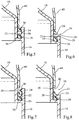
figure 5 , une vue en coupe d'un détail du dispositif de bouchage de lafigure 1 , en position fermée avant première ouverture; - la
figure 6 , une vue en coupe d'un détail du dispositif de bouchage de lafigure 1 , en position fermée avant première ouverture; - la
figure 7 , une vue dans le plan de coupe de lafigure 5 d'un détail du dispositif de bouchage de lafigure 1 , en position refermée après première ouverture; - la
figure 8 , une vue dans le plan de coupe de lafigure 6 d'un détail du dispositif de bouchage de lafigure 1 , en position refermée après première ouverture; - la
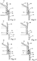
figure 9 , une vue isométrique d'un dispositif de bouchage en deux pièces selon un deuxième mode de réalisation de l'invention, avant assemblage en position fermée; - la
figure 10 , une vue isométrique du dispositif de bouchage de lafigure 9 , après assemblage, en position fermée, avant première ouverture; - la
figure 11 , une vue isométrique du dispositif de bouchage de lafigure 9 , en position ouverte; - la
figure 12 , une en coupe d'un détail du dispositif de bouchage de lafigure 9 , en position fermée avant première ouverture; - la
figure 13 , une vue en coupe d'un détail du dispositif de bouchage de lafigure 9 , en position fermée avant première ouverture; - la
figure 14 , une vue en coupe d'un détail du dispositif de bouchage de lafigure 9 , en position fermée avant première ouverture; - la
figure 15 , une vue dans le plan de coupe de lafigure 12 d'un détail du dispositif de bouchage de lafigure 9 , en position refermée après première ouverture; - la
figure 16 , une vue dans le plan de coupe de lafigure 13 d'un détail du dispositif de bouchage de lafigure 9 , en position refermée après première ouverture; - la
figure 17 , une vue dans le plan de coupe de lafigure 14 d'un détail du dispositif de bouchage de lafigure 9 , en position refermée après première ouverture;
- the
figure 1 an isometric view of a closure device in two parts, after assembly and in closed position before a first opening, according to a first embodiment of the invention; - the
figure 2 , an isometric view of the closure device of thefigure 1 , in the open position; - the
figure 3 , a view from behind of the two parts of the closure device of thefigure 1 before assembly; - the
figure 4 , a side view of the two parts of the closure device of thefigure 1 before assembly; - the
figure 5 , a sectional view of a detail of the closure device of thefigure 1 , in the closed position before first opening; - the
figure 6 , a sectional view of a detail of the closure device of thefigure 1 , in the closed position before first opening; - the
figure 7 , a view in the section plane of thefigure 5 a detail of the closure device of thefigure 1 , in the closed position after first opening; - the
figure 8 , a view in the section plane of thefigure 6 a detail of the closure device of thefigure 1 , in the closed position after first opening; - the
figure 9 , an isometric view of a two-piece closure device according to a second embodiment of the invention, before assembly in the closed position; - the
figure 10 , an isometric view of the closure device of thefigure 9 , after assembly, in the closed position, before first opening; - the
figure 11 , an isometric view of the closure device of thefigure 9 , in the open position; - the
figure 12 , a section of a detail of the closure device of thefigure 9 , in the closed position before first opening; - the
figure 13 , a sectional view of a detail of the closure device of thefigure 9 , in the closed position before first opening; - the
figure 14 , a sectional view of a detail of the closure device of thefigure 9 , in the closed position before first opening; - the
figure 15 , a view in the section plane of thefigure 12 a detail of the closure device of thefigure 9 , in the closed position after first opening; - the
figure 16 , a view in the section plane of thefigure 13 a detail of the closure device of thefigure 9 , in the closed position after first opening; - the
figure 17 , a view in the section plane of thefigure 14 a detail of the closure device of thefigure 9 , in the closed position after first opening;
Pour plus de clarté, les éléments identiques ou similaires sont repérés par des signes de référence identiques sur l'ensemble des figures.For the sake of clarity, identical or similar elements are marked with identical reference signs throughout the figures.
Le dispositif de bouchage 10 représenté sur les
La première pièce 12 comporte une embase 16 pourvue d'un relief (non représenté) de fixation à un récipient, pouvant être constitué par exemple, et de manière connue, d'un ou plusieurs filets permettant de visser l'embase à un col de récipient. Cette embase 16 peut le cas échéant, de manière également connue, être équipée à son extrémité inférieure d'une bague d'inviolabilité coopérant avec le col du récipient pour rendre visible toute tentative de séparation entre la première pièce et le col du récipient. La première pièce 12 comporte en outre un verseur 18 faisant saillie en direction axiale par rapport l'embase 16, ce verseur présentant ici une surface extérieure ayant une symétrie de révolution autour d'un axe de référence 100 de la première pièce 12, et une ouverture centrale 19.The
La première pièce 12 présente en outre une gorge annulaire périphérique de fixation 20 visible sur les
La première pièce 12 présente en outre des languettes de retenue 24, ici au nombre de six, séparées deux à deux par des échancrures 26, et faisant saillie depuis l'embase 12 en direction axiale en regard et à faible distance d'une paroi cylindrique 28 du verseur 18. Chacune des languettes de retenue 24 forme une zone d'accrochage avec un crochet 30 faisant saillie radialement vers l'intérieur et vers le verseur 18.The
La deuxième pièce 14 forme un capuchon 32, un anneau fermé de fixation 34 définissant un axe de référence 200 et une charnière 36 reliant l'anneau de fixation 34 au capuchon 32 pour guider le capuchon 32 par rapport à l'anneau 34 entre une position fermée illustrée sur la
La charnière 36 comporte une bande de matière reliée par une extrémité supérieure à une zone de raccord du capuchon 32 et par une extrémité inférieure à l'anneau 34, et des bords latéraux opposés 46, 48 en regard de rebords latéraux correspondants du capuchon 32. Dans au moins une zone située axialement entre d'une part un premier plan perpendiculaire à l'axe de référence 200 et coupant l'extrémité supérieure de la bande et d'autre part un deuxième plan perpendiculaire à l'axe de référence 200 et coupant l'extrémité inférieure de la bande, et s'étendant angulairement autour de l'axe de référence à 60° de part et d'autre des bords latéraux de la bande, la charnière et le capuchon en position fermée ont une enveloppe extérieure commune, ce qui revient à dire que la charnière n'est pas en saillie par rapport à la surface adjacente de la paroi périphérique du capuchon.The
On peut définir un plan géométrique P perpendiculaire à l'axe de référence 200, situé entre la paroi sommitale 38 et l'anneau 34, et en dessous duquel la paroi périphérique 40 présente une enveloppe extérieure sphérique ou plus généralement constituée par une surface de révolution autour de l'axe de référence 200, notamment une surface de révolution ayant une génératrice ayant une concavité tournée vers l'axe de révolution 200. Ce plan P est situé de préférence au-dessus de la charnière 36, entre cette dernière et la paroi sommitale 38. De préférence, la paroi périphérique 40 du capuchon, à son extrémité inférieure, est tangente ou sensiblement tangente à un cylindre de révolution autour de l'axe de référence 200.It is possible to define a geometrical plane P perpendicular to the
La deuxième pièce 14 comporte également un témoin de première ouverture 50 en forme d'arc de cercle s'étendant sensiblement sur un secteur angulaire supérieur à 180° autour de l'axe de référence 200, de préférence depuis un premier bord latéral 46 de la charnière 36 jusqu'à un deuxième bord latéral opposé 48 de la charnière, sans être relié à cette dernière. Le témoin de première ouverture 50 est relié au rebord périphérique 42 de la paroi périphérique 40 du capuchon par des pontets sécables 52, et est positionné axialement entre le rebord périphérique 42 et l'anneau de fixation 34. Comme illustré en particulier sur les
Les deux pièces 12, 14 sont assemblées pour constituer le dispositif de bouchage, en faisant coïncider les axes de référence 100, 200 dans la position illustrée sur les
À la première ouverture du capuchon 32, le témoin de première ouverture 50 est retenu par les crochets 30 des languettes 24, et les pontets 52 sont arrachés, séparant le témoin de première ouverture 50 du capuchon 32. Le témoin de première ouverture 50 tombe alors par gravité dans l'espace libre 54 et vient en appui contre l'anneau 34. Cette position est conservée lorsque l'on referme le capuchon 32, comme illustré sur les
La chute du témoin de première ouverture 50 laisse apparaître un espace 58 (
Notons également que dans la mesure où le témoin de première ouverture 50 reste piégé par les languettes 24, on évite la libération dans l'environnement d'une pièce plastique qui pourrait être source de pollution ou présenter un danger en cas d'ingestion par un enfant.Note also that since the
La position ouverte illustrée sur la
Un deuxième mode de réalisation de l'invention va maintenant être décrit en lien avec les
Comme illustré sur les figures, la première pièce 12 du dispositif de bouchage 10 selon le deuxième mode de réalisation ne comporte qu'une échancrure 26 s'étendant sur un angle de moins de 180°, et de préférence d'environ 60 à 120°, de préférence diamétralement à l'opposé de la charnière 36. De part et d'autre de cette échancrure 26 est constituée une gorge 20 qui court dans le sens périphérique d'un bord de l'échancrure 26 à l'autre, donc sur un secteur angulaire de plus de 180°, complémentaire de celui de l'échancrure 26. La gorge 20 est pourvue d'un relief de fixation 22, faisant saillie radialement vers l'intérieur et vers une paroi cylindrique 28 du verseur 18.As illustrated in the figures, the
La deuxième pièce 14 comporte un capuchon 32 dont la paroi périphérique 40 présente une échancrure 41 pour loger au moins partiellement un témoin de première ouverture 50 qui est relié à la paroi périphérique 40 par des pontets sécables 52 situés au niveau de cette échancrure 41. L'anneau de fixation 34 de la deuxième pièce 14 comporte un segment 35 de hauteur réduite au niveau du témoin de première ouverture 50, pour laisser entre le témoin de première ouverture 50 et l'anneau de fixation 34 un espace suffisant 54, visible par l'échancrure 26. De part et d'autre du segment 35, l'anneau de fixation 34 présente une hauteur plus importante et est pourvu d'un relief de fixation 56 en saillie radiale vers l'extérieur, qui court sensiblement jusqu'au bord latéral correspondant 46, 48 de la charnière 36. Le témoin de première ouverture 50 présente dans le sens circonférentiel une longueur légèrement plus importante que l'échancrure 26 et comporte à ses extrémités deux reliefs d'accrochage 58, situés dans le prolongement des reliefs de fixation 56 de l'anneau de fixation 34. Les extrémités de la gorge de fixation 20 sont ainsi disposées en regard des deux reliefs d'accrochage 58, et constituent deux zones d'accrochage pour le témoin de première ouverture 50. En dehors de ces deux zones d'accrochage, la gorge de fixation 20 permet de loger et de retenir l'anneau de fixation 34.The
À l'assemblage, on aligne les axes de référence 100, 200 des deux pièces 12, 14 et on les positionne angulairement l'une par rapport à l'autre, avant de les rapprocher. L'anneau 34 vient s'encliqueter dans la gorge 20, et les reliefs de fixation 58 viennent s'encliqueter dans les zones d'accrochage aux deux extrémités de la gorge 20.At the assembly, the reference axes 100, 200 of the two
À la première ouverture, le témoin de première ouverture 50 se trouve bloqué au niveau des zones d'accrochage, les pontets 52 sont arrachés et le capuchon 32 est ouvert alors que le témoin de première ouverture 50 tombe par gravité dans l'espace libre 54, au contact du segment aminci 35 de l'anneau de fixation 34, comme illustré sur les
Naturellement, de nombreuses variantes sont possibles. Pour limiter la déformation en flexion du témoin de première ouverture 50 lors de l'arrachage des pontets 52, on peut avoir intérêt à positionner ceux-ci uniquement à proximité des extrémités du témoin de première ouverture et des reliefs d'accrochage 58.Of course, many variations are possible. To limit the bending deformation of the
La forme de la charnière 36 et celle du capuchon 32, qui dans les modes de réalisation présentés ont été choisies pour conférer une bonne tenue mécanique à la deuxième pièce 14 et pour minimiser la consommation de matière, peuvent toutefois varier suivant notamment des considérations esthétiques. Le verseur 18 peut être de tout type et n'est pas nécessairement centré sur l'axe de référence 200 de la deuxième pièce.The shape of the
Dans une variante du premier mode de réalisation, on peut prévoir que le relief annulaire de fixation 22 prévu sur la première pièce 12 pour la fixation de l'anneau 34 soit en saillie radialement vers l'extérieur depuis la paroi cylindrique 28 du verseur. De même, les crochets d'accrochage 30 peuvent être disposés sur la paroi cylindrique 28 du verseur, et orientés radialement vers l'extérieur. Les languettes de retenue 24 ont alors uniquement une fonction de retenue de l'anneau 34 et du témoin de première ouverture 50. Cette remarque vaut de manière similaire pour le deuxième mode de réalisation.In a variant of the first embodiment, it can be provided that the
Naturellement, l'invention, telle que définie par les revendications, est applicable à des dispositifs de bouchage ayant des formes extérieures variées.Naturally, the invention, as defined by the claims, is applicable to capping devices having various external forms.
Claims (9)
- A closure device (10) to be fastened to a container neck, with the closure device (10) comprising:- a first part (12) forming a base (16) for fixing to the container neck and having at least one fixing peripheral groove (20);- a second part (14) forming a cap (32), with a fixing ring (34) defining a reference geometrical axis (200), and a hinge (36) connecting the holding ring (34) to the cap (32) for guiding the cap (32) relative to the fixing ring (34) between a closed position and an open position, with the fixing ring (34) being snap-fitted into the fixing groove (20) of the first part;characterized in that the second part (14) further forms a first opening indicator (50) and a frangible connection (52) between the first opening indicator (50) and a peripheral rim (42) of the cap, with a free space (54) being preserved in the axial direction between the fixing ring (34) and the first opening indicator (50) in the closed position prior to the first opening, with the first opening indicator (50) being held by at least one latching area (30) of the first part so as to be separated from the cap (32) and fall into the gap (54) upon first opening.
- A closure device according to the preceding claim, characterized in that the first part (12) comprises at least two areas (30) for latching the first opening indicator (50), and at least a visual control cut (26) separating the two latching areas (30) and making visible, in the closed position prior to the first opening, the first opening indicator (50) and the free space (56).
- A closure device according to the preceding claim, characterized in that said latching areas (30) are more than two in number, preferably distributed over the entire periphery of the first part (12) and are separated two by two by cuts (26), at least one of which is a visual control cut making visible, in the closed position prior to the first opening, the first opening indicator (50) and the free space (56).
- A closure device according to any one of the preceding claims, characterized in that the area(s) (30) for latching the first part cooperate (s) with the first opening indicator (50) so as to oppose the extraction of the first opening indicator (50) after the first opening.
- A closure device according to any one of the preceding claims, characterized in that the first opening indicator (50) has the shape of an arc of circle about the reference axis (200).
- A closure device according to the preceding claim, characterized in that the arc of circle runs over an angular sector greater than 45° about the reference axis, and preferably less than 180°, for example of the order of 60°, 90° or 120°.
- A closure device according to the preceding claim, characterized in that the arc of circle runs over an angular sector greater than 180° about the reference axis, preferably from a first side edge (46) of the hinge up to a second opposite side edge (48) of the hinge.
- A closure device according to any one of the preceding claims, characterized in that the hinge (36) comprises a strip of material connected through an upper end to a connecting area of the cap (32) and through a lower end to the fixing ring (34), and opposite side edges (46, 48) facing matching side rims of the cap (32).
- A closure device according to the preceding claim, characterized in that, in the closed position, the hinge (36) does not protrude with respect to a peripheral wall of the cap.
Applications Claiming Priority (1)
| Application Number | Priority Date | Filing Date | Title |
|---|---|---|---|
| FR1363511A FR3015442B1 (en) | 2013-12-24 | 2013-12-24 | ARTICULATED CLAMPING DEVICE WITH FIRST OPENING INDICATOR |
Publications (2)
| Publication Number | Publication Date |
|---|---|
| EP2889232A1 EP2889232A1 (en) | 2015-07-01 |
| EP2889232B1 true EP2889232B1 (en) | 2016-12-14 |
Family
ID=50179844
Family Applications (1)
| Application Number | Title | Priority Date | Filing Date |
|---|---|---|---|
| EP14199569.6A Not-in-force EP2889232B1 (en) | 2013-12-24 | 2014-12-22 | Hinged closure device with first-opening indicator |
Country Status (8)
| Country | Link |
|---|---|
| US (2) | US9975669B2 (en) |
| EP (1) | EP2889232B1 (en) |
| AU (1) | AU2014277846B2 (en) |
| CA (1) | CA2876650A1 (en) |
| ES (1) | ES2619621T3 (en) |
| FR (1) | FR3015442B1 (en) |
| MX (1) | MX2014015908A (en) |
| RU (1) | RU2700953C2 (en) |
Families Citing this family (22)
| Publication number | Priority date | Publication date | Assignee | Title |
|---|---|---|---|---|
| CA2991262C (en) | 2015-07-17 | 2023-09-26 | Nestec S.A. | Tamper-evident closure |
| GB201516189D0 (en) * | 2015-09-14 | 2015-10-28 | Obrist Closures Switzerland | Head stand closure with a tamper-evident seal |
| ITUB20169888A1 (en) * | 2016-01-11 | 2017-07-11 | Capsol S P A | Anti-tampering system of containers |
| EP3444201B1 (en) * | 2016-04-13 | 2021-11-03 | Betapack, S.A.U. | Closure device comprising an opening indicator |
| BR112019002454A2 (en) * | 2016-09-29 | 2019-05-14 | Creanova Universal Closures Ltd. | closure |
| CN108249034A (en) * | 2016-12-28 | 2018-07-06 | 广州大正新材料科技有限公司 | A kind of edible oil packing bottle cap |
| US10759554B2 (en) * | 2017-02-02 | 2020-09-01 | Rai Strategic Holdings, Inc. | Dispenser unit for aerosol precursor |
| CA179103S (en) * | 2017-07-13 | 2019-06-12 | Chubby Gorilla Inc | Bottle |
| GB201716075D0 (en) * | 2017-10-02 | 2017-11-15 | Obrist Closures Switzerland | A closure |
| US10427823B2 (en) * | 2017-10-25 | 2019-10-01 | Silgan White Cap LLC | Lightweight neck finish for a container |
| USD912462S1 (en) * | 2017-11-03 | 2021-03-09 | Cirkul, Inc. | Beverage additive cartridge cap |
| US10683146B2 (en) * | 2017-12-12 | 2020-06-16 | ENI-JR286, Inc. | Lid assembly with button-actuated rotating straw mechanism |
| EP3724095A1 (en) * | 2017-12-15 | 2020-10-21 | Creanova Universal Closures Ltd. | Closure |
| ES1217541Y (en) * | 2018-07-03 | 2018-12-10 | Sanchez Jose Francisco Gonzalez | Closing cap for containers |
| ES1217781Y (en) * | 2018-07-26 | 2018-12-14 | Betapack S A U | Cap with opening indicator |
| WO2020061579A1 (en) * | 2018-09-21 | 2020-03-26 | Novembal Usa Inc. | Tethered plastic stopper |
| WO2020061582A1 (en) * | 2018-09-23 | 2020-03-26 | Novembal Usa Inc. | Tethered plastic stopper |
| US10829274B2 (en) | 2018-11-15 | 2020-11-10 | Closure Systems International Inc. | Flip-top closure |
| MX2021010957A (en) * | 2019-03-26 | 2021-10-13 | Tetra Laval Holdings & Finance | Opening device for a packaging for pourable products. |
| US11059633B2 (en) | 2019-10-31 | 2021-07-13 | Cheer Pack North America | Flip-top closure for container |
| US20220402666A1 (en) * | 2019-11-07 | 2022-12-22 | Aptar Freyung Gmbh | Closure device |
| USD997638S1 (en) * | 2021-02-05 | 2023-09-05 | Betapack, S.A.U. | Cap for bottle |
Citations (18)
| Publication number | Priority date | Publication date | Assignee | Title |
|---|---|---|---|---|
| US6116477A (en) | 1999-12-13 | 2000-09-12 | Courtesy Corporation | Two piece hinge closure |
| WO2002028735A1 (en) | 2000-10-03 | 2002-04-11 | Seaquist Closures Foreign, Inc. | Closure lid and resealable closure system |
| DE20117343U1 (en) | 2001-10-23 | 2003-03-06 | Gizeh Verpackungen Gmbh & Co K | Sealing cap for container holding liquid or pourable substance has recess in bottom section accessible from wall facing cover and into which fits originality seal securing element during first closure of cover |
| JP2003160162A (en) | 2001-11-27 | 2003-06-03 | Yoshino Kogyosho Co Ltd | Cap |
| US20030189065A1 (en) | 2002-04-05 | 2003-10-09 | Gene Stull | Multi-piece snap-together cap |
| WO2004007313A1 (en) | 2002-07-12 | 2004-01-22 | Bericap | Closure comprising a hinged cap moulded in closed position |
| US20060011573A1 (en) | 2004-07-16 | 2006-01-19 | Herald Coy M | Tamper-indicating dispensing closure |
| WO2007006892A1 (en) | 2005-07-12 | 2007-01-18 | Bericap | Closure with pouring means |
| WO2007026194A1 (en) | 2005-08-31 | 2007-03-08 | Gefit S.P.A. | “flip-top” closure for liquid containes, in particular for bottles |
| EP1892194A1 (en) | 2006-08-22 | 2008-02-27 | Obrist Closures Switzerland GmbH | A tamper-evident closure |
| US20080110933A1 (en) | 2006-11-14 | 2008-05-15 | Goncalves Joao Alberto Ferreir | Tamper-indicating dispensing closure |
| FR2911328A1 (en) | 2007-01-16 | 2008-07-18 | Bericap Soc Responsabilite Lim | Two-piece stopper for e.g. oil bottle, has base comprising counter-stop that cooperates with stop of enclosure for indexing angular position of base with respect to enclosure around mounting axis, where enclosure has unit pivoting cap |
| WO2010004195A2 (en) | 2008-07-07 | 2010-01-14 | Tetra Laval Holdings & Finance S.A. | Device for plugging the neck of a container and method for manufacturing this device |
| WO2010112801A1 (en) | 2009-04-02 | 2010-10-07 | Obrist Closures Switzerland Gmbh | A closure |
| US20110000928A1 (en) | 2008-02-26 | 2011-01-06 | Tetra Laval Holdings & Finance S.A. | Device for plugging the neck of a vessel |
| US20110100990A1 (en) | 2009-11-02 | 2011-05-05 | Berry Plastics Corporation | Tamper-evident container closure with flip-top cap |
| WO2011085011A2 (en) | 2010-01-05 | 2011-07-14 | Sd Ip Holdings Company | Multi-piece closure with hinged lid |
| WO2012131097A1 (en) | 2011-03-31 | 2012-10-04 | Bericap | Stopper device provided with a first-opening indicator |
Family Cites Families (198)
| Publication number | Priority date | Publication date | Assignee | Title |
|---|---|---|---|---|
| US2162752A (en) * | 1934-10-19 | 1939-06-20 | John Hamberger | Tamperproof closure |
| US2162754A (en) | 1937-06-05 | 1939-06-20 | John Hamberger | Tamperproof closure and container |
| US2361464A (en) | 1940-04-02 | 1944-10-31 | Du Pont | Article of manufacture |
| US2961119A (en) | 1957-11-25 | 1960-11-22 | Charles F Leach | Closure devices |
| US3117701A (en) | 1958-04-11 | 1964-01-14 | Continental Can Co | Dispensing closure and container |
| FR1303608A (en) | 1961-08-03 | 1962-09-14 | Closing device for bottles or the like | |
| FR1462219A (en) | 1965-06-29 | 1966-04-15 | Trefimetaux | Composite screw cap with warranty strip |
| US3463341A (en) | 1967-12-18 | 1969-08-26 | Roehr Metals & Plastics Co | Tamper-indicating closure |
| DE2216343B2 (en) | 1972-04-05 | 1975-05-15 | Hermann 7071 Lindach Grau | Safety screw cap |
| US3823841A (en) | 1972-04-13 | 1974-07-16 | American Hospital Supply Corp | Closure system for sterile medical liquid container |
| US3892326A (en) | 1973-11-09 | 1975-07-01 | Eyelet Specialty Co | Safety closure for a metal container |
| IT1000576B (en) | 1974-01-08 | 1976-04-10 | Fiscem Spa | CLOSURE FOR PART CONTAINERS FOR BOTTLES AND BOTTLES |
| DE7426691U (en) | 1974-08-06 | 1974-11-14 | Behringwerke Ag | Plastic cap |
| DE7441004U (en) | 1974-12-10 | 1975-05-07 | Behringwerke Ag | Bottle for sterile storage especially of pharmaceutical preparations |
| AR208410A1 (en) | 1975-04-10 | 1976-12-27 | Tomiati U | SAFETY COVER |
| FR2309425A1 (en) | 1975-04-29 | 1976-11-26 | Angelino Roger | Two-part plastics pouring stopper - has inner part inserted into bottle neck and covering cap clipped into place |
| GB1569781A (en) | 1977-03-02 | 1980-06-18 | Johnsen Jorgensen Plastics Ltd | Closure |
| FR2407140A1 (en) | 1977-10-25 | 1979-05-25 | Angelino Roger | Pouring vessel hinging cap - has distorting lip in hinge zone engaged by protrusion to lock cap in open position |
| US4299328A (en) | 1980-03-26 | 1981-11-10 | Anchor Hocking Corporation | Tamperproof bottle closure cap |
| US4322012A (en) | 1980-05-09 | 1982-03-30 | Dairy Cap Corporation | Threaded plastic bottle cap |
| US4322009A (en) | 1980-05-19 | 1982-03-30 | Owens-Illinois, Inc. | Tamper proof molded plastic closure |
| NL181496C (en) | 1980-09-08 | 1987-09-01 | Int Verpakking Mij Bv | HOLDER CLOSURE. |
| US4418828A (en) | 1981-07-24 | 1983-12-06 | H-C Industries, Inc. | Plastic closure with mechanical pilfer band |
| DE3139526A1 (en) | 1981-10-05 | 1983-04-21 | Albert Obrist AG, 4153 Reinach, Basel | Closure cap made of plastic material |
| EP0076778A1 (en) | 1981-10-05 | 1983-04-13 | Crown Obrist AG | Closure of plastics material |
| JPS58502165A (en) | 1981-12-23 | 1983-12-15 | アンステイテユ・パストウ−ル | Method of detecting the presence of a nucleic acid sequence using a modified nucleic acid probe that can be recognized by a specific antibody |
| FR2524425B1 (en) | 1982-03-31 | 1985-07-12 | Boussois Souchon Neuvesel Sa | PLUG IN SYNTHETIC MATERIAL EQUIPPED WITH A RING OF INVIOLABILITY |
| JPS59500667A (en) | 1982-04-23 | 1984-04-19 | セ バ ル | Plastic screw cap with improved sealing tape |
| EP0093690A1 (en) | 1982-05-04 | 1983-11-09 | Crown Obrist AG | Closure for a container |
| USD280802S (en) | 1982-10-25 | 1985-10-01 | Cho Joong H | Bottle cap for edible oil |
| US4442947A (en) | 1983-01-18 | 1984-04-17 | Continental White Cap, Inc. | Plastic closure with sealing flaps |
| US4458820A (en) | 1983-02-14 | 1984-07-10 | Martin Abrams | Tamper-indicating arrangement for a container |
| US4474301A (en) | 1983-03-14 | 1984-10-02 | Johnsen & Jorgensen (Plastics) Ltd. | Tamper-resistant and childproof closure |
| CA1206924A (en) | 1983-03-30 | 1986-07-02 | Paul F. Roos | Tap |
| US4595123A (en) | 1983-06-17 | 1986-06-17 | Owens-Illinois, Inc. | Tamper evident closure cap |
| US4494663A (en) | 1984-01-05 | 1985-01-22 | Abbott Laboratories | Sterile solution container |
| EP0308995A3 (en) | 1984-01-18 | 1989-04-05 | Japan Crown Cork Co. Ltd. | Pilfer-proof plastic closure for containers |
| IT1209493B (en) | 1984-01-23 | 1989-08-30 | Giuseppe Bagnato | SCREW CAP FOR SPARKLING WINES, D.O.C. AND OTHERS. |
| US4487324A (en) | 1984-02-08 | 1984-12-11 | Seaquist Closures | Tamper-evident dispensing closure |
| US4565294A (en) | 1984-02-23 | 1986-01-21 | Smith Moe S | Tamper evident container shroud |
| GB2159123B (en) | 1984-05-23 | 1989-04-05 | Yoken Co Ltd | A container |
| US5417350A (en) | 1984-09-19 | 1995-05-23 | Kerr Group, Inc. | Flip top closure |
| US4909404A (en) | 1984-12-10 | 1990-03-20 | Oleg Rozenberg | Tamper-evident closures |
| US4635823A (en) | 1985-05-09 | 1987-01-13 | Gene Stull | Dispensing closure construction |
| DE3528815A1 (en) | 1985-08-10 | 1987-02-12 | Berg Jacob Gmbh Co Kg | WELDED PLASTIC LOCK FOR PLASTIC CONTAINERS, METHOD FOR PRODUCING THE SAME AND DEVICE FOR IMPLEMENTING THE METHOD |
| US4598833A (en) | 1985-08-29 | 1986-07-08 | Kerr Glass Manufacturing Corporation | Tamper-evident child-resistant closure |
| FR2600978B1 (en) | 1986-05-12 | 1990-06-08 | Astra Plastique | DISPENSING CAP WITH ROTATING CAP FOR PASTA PRODUCTS |
| US4733787A (en) | 1986-06-02 | 1988-03-29 | Merck & Co., Inc. | Tamper evident overcap |
| USD302120S (en) | 1986-09-09 | 1989-07-11 | Kishimoto Sangyo Co., Ltd. | Nestable packaging container |
| FR2605606B1 (en) | 1986-10-23 | 1989-06-09 | Valois | SECURITY AND INVIOLABILITY DEVICE FOR NASAL-TYPE SPRAYER |
| ES1001409Y (en) | 1987-01-12 | 1989-08-01 | Vem De Tapas Metalicas S.A. | COMPLEX CAP FOR CLOSING AND SEALING OF BOTTLES |
| US4709823A (en) | 1987-02-05 | 1987-12-01 | James M. Beck | Tamper evident bottle or package closure |
| US4711363A (en) | 1987-05-01 | 1987-12-08 | West Penn Plastic, Inc. | Tamper evidence closure |
| US4984699A (en) | 1987-05-21 | 1991-01-15 | Zalut Gregory J | Tamper evident cap |
| US4874101A (en) | 1987-05-21 | 1989-10-17 | Zalut Gregory J | Tamper evident cap |
| US4747501A (en) | 1987-07-08 | 1988-05-31 | National Plastics Limited | Container closure method |
| GB8716514D0 (en) | 1987-07-14 | 1987-08-19 | Waverley Pharma Ltd | Bottle caps |
| ES1002990Y (en) | 1987-07-22 | 1990-04-01 | Bericap,S.A. | PERFECTED SEAL-PLUG |
| BE1000760A6 (en) | 1987-07-27 | 1989-03-28 | Lynes Holding Sa | POURING CAP DEVICE. |
| DE3811362A1 (en) | 1987-12-02 | 1989-06-22 | Stolz Heinrich Kg | Container fitted with a closure |
| DK159542C (en) | 1988-02-15 | 1991-04-02 | Dumex Ltd As | CONTAINER WITH SCREW COVER INCLUDING A SECURITY |
| US4795044A (en) | 1988-04-21 | 1989-01-03 | Owens-Illinois Closure Inc. | Tamper evident closure with snap-type hinge cap |
| US5395015A (en) | 1988-07-01 | 1995-03-07 | Bolen, Jr.; Robert J. | Dispensing closure with a modified lid for increased opening angle |
| US5005718A (en) | 1988-08-04 | 1991-04-09 | Van Blarcom Closures, Inc. | Tamper-evident child resistant closure device |
| US4936475A (en) | 1988-09-19 | 1990-06-26 | Sunbeam Plastics Corporation | Threaded tamper indicating closure |
| USD319981S (en) | 1988-10-17 | 1991-09-17 | Specialty Packaging Licensing Company | Pour spout for containers |
| ES2041441T3 (en) | 1988-11-28 | 1993-11-16 | Crown Cork Ag | THREADED PLUG WITH GUARANTEE TAPE. |
| ES1009616Y (en) | 1989-03-14 | 1990-02-16 | Ultimos Desarrollos, S.A. (Uldesa) | STOP DEVICE FOR PLUG THREADS. |
| FR2645125B1 (en) | 1989-03-28 | 1991-07-26 | Simon Patrick | SEALED CLOSURE DEVICE FOR CONTAINERS AND METHOD FOR THE PRODUCTION THEREOF |
| US5219507A (en) | 1989-07-27 | 1993-06-15 | Owens-Illinois Closure Inc. | Method of making a tamper indicating package |
| US5090788A (en) | 1989-07-27 | 1992-02-25 | Owens-Illinois Closure Inc. | Tamper indicating package |
| US5080246A (en) | 1989-09-01 | 1992-01-14 | Anchor Hocking Packaging Company | Closure having a spring open tamper evidencing band |
| US5058755A (en) | 1989-09-01 | 1991-10-22 | Anchor Hocking Packaging Company | Tamper indicating closure having retaining hoop with relief windows |
| FR2655953B1 (en) | 1989-12-15 | 1992-02-21 | Cebal | IMPROVEMENT IN THE CAPPING OF CONTAINERS WITH CAPSULE WITH SCREW CAPS AND WITH REMOVABLE GUARANTEE STRIP. |
| US5007555A (en) | 1989-12-19 | 1991-04-16 | Creative Packaging Corp. | Biased hinge cap |
| US5007545A (en) | 1990-03-15 | 1991-04-16 | Seaquist Closures | Removal resistant member |
| US4981230A (en) | 1990-03-15 | 1991-01-01 | Continental White Cap, Inc. | Composite cap including tamper indicating band |
| US5104008A (en) | 1990-12-03 | 1992-04-14 | Northern Engineering And Plastics Corp. | Resealable bottle cap with push-pull closure |
| DE59203093D1 (en) | 1991-04-04 | 1995-09-07 | Ernest Rudolf Ag | PLASTIC BOTTLE CAP. |
| US5085332B1 (en) | 1991-04-11 | 1994-04-05 | Gettig Technologies Inc | Closure assembly |
| US5147054A (en) | 1991-05-20 | 1992-09-15 | Pehr Harold T | Tamper-proof container |
| DE4128474A1 (en) | 1991-08-28 | 1993-03-04 | Berg Jacob Gmbh Co Kg | PLASTIC SCREW CAP FOR PRESSURIZED BOTTLES |
| CH683611A5 (en) | 1991-09-10 | 1994-04-15 | Zeller Plastik Koehn Graebner | Methods and tools for producing a closure for containers as well as by the process produced closure. |
| JP2557154Y2 (en) | 1991-09-30 | 1997-12-08 | 凸版印刷株式会社 | Liquid container with spout |
| US5176278A (en) | 1992-01-31 | 1993-01-05 | Quarberg Craig D | Beverage can resealing device |
| US5297688A (en) | 1992-03-03 | 1994-03-29 | Creative Packaging Corp. | Closure for sealing a container rim |
| DE9218637U1 (en) | 1992-03-26 | 1994-11-10 | Stolz Heinrich Gmbh | Closure for a container from a closure base and a screw cap |
| US5289932A (en) | 1992-04-15 | 1994-03-01 | Canada Plastic Containers Limited | Closure cap with plastic liner |
| US5297696A (en) | 1992-04-27 | 1994-03-29 | International Paper Company | Pour spout with piercing insert |
| US5356019A (en) | 1992-10-14 | 1994-10-18 | Crown Cork & Seal Company, Inc. | Tamper indicating plastic closure |
| US6817276B1 (en) | 1993-04-19 | 2004-11-16 | Owens-Illinois Closure Inc. | Apparatus for forming bridges in tamper-indicating closures |
| US5400912A (en) | 1993-05-10 | 1995-03-28 | Courtaulds Packaging Inc. | Closure with concealed hinge |
| USD367424S (en) | 1993-05-19 | 1996-02-27 | Zeller Plastik Gmbh | Closure device with screw thread |
| GB9322113D0 (en) | 1993-10-27 | 1993-12-15 | Sturk Ron | Closure for containers |
| EP0661218B1 (en) | 1993-12-23 | 1998-07-29 | Crown Cork AG | Plastic closure cap with early venting inner seal |
| IL112387A (en) | 1994-02-01 | 1997-07-13 | Crown Cork Ag | Screwable closure cap with security against over- tightening |
| US5482176A (en) | 1994-03-16 | 1996-01-09 | The West Company, Incorporated | Membrane piercing closure and spout assembly |
| DE4410790A1 (en) | 1994-03-28 | 1995-10-05 | Berg Jacob Gmbh Co Kg | Screw cap with welding ring |
| FR2719559B1 (en) * | 1994-05-06 | 1996-07-26 | Rical Sa | Closing cap for a container having a collar with a unique hanging collar. |
| USD385491S (en) | 1994-05-12 | 1997-10-28 | Aptargroup, Inc. | Closure for a container |
| FR2721282B1 (en) | 1994-06-21 | 1996-12-27 | Moulage Automatique Sa | Improvement to a manufacturing process of a plugging device and machine for its implementation. |
| DE4425675C3 (en) | 1994-07-20 | 2001-02-15 | Frank Schellenbach | Sealing cap |
| USD374821S (en) | 1995-01-13 | 1996-10-22 | Lermer Packaging Corp. | Container closure |
| DE69632524T2 (en) | 1995-01-30 | 2005-05-12 | Portola Packaging, Inc., San Jose | OUTLET DEVICE WITH REMOVABLE MEMBRANE |
| US5785193A (en) | 1995-02-15 | 1998-07-28 | Yoshino Kogyosho Co., Ltd. | Snap-hinged cap |
| US5725115A (en) | 1995-02-21 | 1998-03-10 | Crown Cork Ag | Closure cap with tether |
| US5810185A (en) | 1995-03-02 | 1998-09-22 | Groesbeck; Robert Clay | Reclosable bottle closure for carbonated beverages and the like |
| FR2732316B1 (en) | 1995-03-31 | 1997-05-30 | Rical Sa | DISPENSER FOR SUPPLYING A LIQUID FROM A CONTAINER |
| US5964363A (en) | 1995-04-05 | 1999-10-12 | Crown Cork & Seal Technologies Corporation | Tamper evident bottle cap |
| FR2737706B1 (en) | 1995-08-11 | 1997-10-10 | Janvier Ets | DEVICE FOR SEALING A CONTAINER AND FOR DISPENSING THE PRODUCT THEREIN |
| US5685444A (en) | 1995-09-19 | 1997-11-11 | Valley; Joseph P. | Tamper-evident hinged closure cap construction |
| US5662247A (en) | 1995-09-28 | 1997-09-02 | West Penn Plastics | Tamper evident push pull resealable cap |
| US5960992A (en) | 1995-10-03 | 1999-10-05 | International Paper Company | Aseptic brick package spout |
| DE29623290U1 (en) | 1995-10-31 | 1998-02-19 | Safety Cap System Ag | Closure for a bottle or the like. |
| US5641099A (en) | 1995-12-08 | 1997-06-24 | Rieke Corporation | Nestable pouring spout assembly |
| FR2744101B1 (en) | 1996-01-26 | 1998-03-20 | Astra Plastique | PLUG OF SYNTHETIC MATERIAL HAVING AN ARTICULATED LID |
| US5660290A (en) | 1996-03-27 | 1997-08-26 | Carnaudmetalbox (Holdings) Usa Inc. | Closure fitting for unthreaded containers |
| US5799840A (en) | 1996-04-25 | 1998-09-01 | Tetra Laval Holdings & Finance, S A | Closure formed as a single, integral part |
| DE29610125U1 (en) | 1996-06-08 | 1996-08-29 | Herberts Gmbh | Device for closing containers |
| JP3617732B2 (en) | 1996-07-10 | 2005-02-09 | 大和製罐株式会社 | Retort sterilizable container |
| US5762228A (en) | 1996-07-26 | 1998-06-09 | Dart Industries Inc. | Vented seal with rocking vent cover |
| USD405012S (en) | 1996-10-09 | 1999-02-02 | Bericap Gmbh & Co. Kg | Screw cap |
| JP4318754B2 (en) | 1996-11-01 | 2009-08-26 | テトラ ラバル ホールデイングス エ フイナンス ソシエテ アノニム | Integrated molded flip cap closure |
| DE19705717A1 (en) | 1997-02-14 | 1998-08-20 | Bericap Gmbh & Co Kg | Plastic screw cap |
| DE19708909A1 (en) | 1997-03-05 | 1998-09-10 | Bericap Gmbh & Co Kg | Plastic screw closure for bottles |
| DE19712364A1 (en) | 1997-03-25 | 1998-10-01 | Bericap Gmbh & Co Kg | Bottle snap closure cap |
| US5846471A (en) | 1997-04-01 | 1998-12-08 | Kerr Group, Inc. | Method for manufacturing a tamper-evident closure |
| US5975369A (en) | 1997-06-05 | 1999-11-02 | Erie County Plastics Corporation | Resealable pushable container closure and cover therefor |
| AU132271S (en) | 1997-06-12 | 1997-11-25 | A tamper-evident pull-push closure | |
| USD399744S (en) | 1997-06-26 | 1998-10-20 | Aptargroup, Inc. | Drink spout for a container |
| FR2765194B1 (en) | 1997-06-27 | 1999-09-17 | Rical Sa | SCREW-CLOSER POURER ASSEMBLY FOR A CONTAINER |
| US6981602B2 (en) | 1997-08-01 | 2006-01-03 | Portola Packaging, Inc. | Tamper evident bottle cap |
| US5967376A (en) | 1997-08-05 | 1999-10-19 | Rieke Corporation | Insert molded tamper evident pouring spout |
| DE19734874A1 (en) | 1997-08-12 | 1999-02-18 | Alpla Design Lehner Gmbh | Injection moulded container closure system with security feature |
| USD398851S (en) | 1997-08-28 | 1998-09-29 | Zeller Plastik, Inc. | Dispensing closure with pressure actuated valve |
| US5992659A (en) | 1997-09-25 | 1999-11-30 | Pano Cap (Canada) Limited | Tamper proof flip top cap |
| CA2322527C (en) | 1998-02-17 | 2007-04-10 | Elopak A.S. | Improvements in or relating to packaging |
| DE19807768A1 (en) | 1998-02-24 | 1999-08-26 | Bericap Gmbh & Co | Closure for bucket or tub-shaped plastic container has inwards directed |
| JP3198408B2 (en) | 1998-03-04 | 2001-08-13 | 日本酸素株式会社 | Insulated container |
| FR2779127B1 (en) | 1998-06-02 | 2000-07-13 | Crown Cork & Seal Tech Corp | DEVICE WITH A SCREW CAP FOR PACKAGING |
| JP4160163B2 (en) | 1998-06-11 | 2008-10-01 | 日本テトラパック株式会社 | Container with cap |
| EP1044135B1 (en) | 1998-07-14 | 2002-10-09 | Amersham Health AS | Package comprising a container with a mouth |
| US6050434A (en) | 1998-07-23 | 2000-04-18 | Mcnab; Donald W. | Container closure with double-axis resiliently-biasing web-hinge structure |
| US6371317B1 (en) | 1998-08-07 | 2002-04-16 | Kerr Group, Inc. | Tamper indicating closure with foldable tab |
| US7344039B2 (en) | 1998-08-07 | 2008-03-18 | Berry Plastics Corporation | Tamper indicating band having foldable tabs including tab extensions, tamper indicating closure including such tamper indicating band, and tamper indicating closure including such tamper indicating band and container |
| IT1304486B1 (en) | 1998-09-09 | 2001-03-19 | Sacmi | SCREW CAP IN PLASTIC MATERIAL WITH GUARANTEE RING. |
| US6095382A (en) | 1998-09-21 | 2000-08-01 | Aptargroup, Inc. | Container and closure with dispensing valve and separate releasable internal shipping seal |
| DE19851331A1 (en) | 1998-11-06 | 2000-05-11 | Bericap Technologies Rical Sa | Cap for threaded neck bottles |
| US6119883A (en) | 1998-12-07 | 2000-09-19 | Owens-Illinois Closure Inc. | Tamper-indicating closure and method of manufacture |
| CA2275012C (en) | 1999-06-15 | 2006-06-13 | Gilles Decelles | Dual tamper evident closure |
| GB2353519B (en) | 1999-08-26 | 2001-08-01 | Bericap Uk Ltd | Dairy bottle closure |
| JP3145367B1 (en) | 1999-09-02 | 2001-03-12 | 河野樹脂工業株式会社 | Pill fur proof cap |
| FR2798910B1 (en) | 1999-09-29 | 2002-03-08 | Jean Pierre Sittler | DISTRIBUTOR CAP WITH TOTAL CLOSURE AND REINFORCED SEAL FOR BOTTLES OR OTHER CONTAINERS WITH THREADED NUTS |
| EP1088765A1 (en) | 1999-10-01 | 2001-04-04 | Tetra Laval Holdings & Finance SA | Resealable opening device for sealed packages of pourable food products |
| PT1088764E (en) | 1999-10-01 | 2004-10-29 | Tetra Laval Holdings & Finance | OPENING DEVICE QUESE CAN CLOSE TO SEALED PACKAGING OF FOOD PRODUCTS THAT CAN BE VANISHED |
| GB2358626A (en) | 2000-01-26 | 2001-08-01 | Bericap Uk Ltd | Screw on container closures |
| DE10021541C2 (en) | 2000-05-03 | 2002-10-17 | Guenter Grittmann | Retractable tap with original fuse for liquid containers |
| WO2002028728A1 (en) | 2000-10-03 | 2002-04-11 | Terxo Ag | Plastic closing device with a piercing element |
| CA2411402C (en) | 2000-12-21 | 2011-01-04 | Yoshino Kogyosho Co., Ltd. | Synthetic resin bottle cap unit |
| US6478184B2 (en) * | 2001-01-24 | 2002-11-12 | Courtesy Corporation | Two piece hinged closure |
| FR2820120A1 (en) * | 2001-01-30 | 2002-08-02 | Crown Cork & Seal Tech Corp | CAP WITH POURING ORIFICE CLOSED BY A LID AND LID INVIOLABILITY SYSTEM |
| DK1262412T3 (en) | 2001-05-29 | 2006-12-04 | Tetra Laval Holdings & Finance | Re-sealable opening device for sealed packages with pourable food products |
| US7077278B2 (en) | 2001-06-18 | 2006-07-18 | Bericap Holding Gmbh | Screw cap comprising a tamper-evident band |
| FR2828174B1 (en) | 2001-07-31 | 2003-09-26 | Rical Sa | DEVICE FOR SEALING A CONTAINER AND FOR DRAWING A FLUID PRODUCT |
| US6644487B2 (en) * | 2001-08-17 | 2003-11-11 | Seaquist Closures Foreign, Inc. | Tamper-evident closure with break-off piece retention |
| USD463280S1 (en) | 2001-11-08 | 2002-09-24 | Owens-Illinois Closure Inc. | Closure |
| US6659297B2 (en) | 2001-11-28 | 2003-12-09 | Owens-Illinois Closure Inc. | Tamper-indicating closure, container, package and methods of manufacture |
| USD480305S1 (en) * | 2002-07-12 | 2003-10-07 | Bericap | Cap |
| USD556575S1 (en) | 2002-07-12 | 2007-12-04 | Bericap | Bottle cap |
| USD530611S1 (en) | 2002-07-12 | 2006-10-24 | Bericap | Bottle cap |
| USD490315S1 (en) | 2002-07-15 | 2004-05-25 | Danny Kiser | Container closure |
| USD512634S1 (en) | 2004-04-09 | 2005-12-13 | Magenta Corporation | Dispensing portion of a closure |
| US20060043052A1 (en) * | 2004-08-25 | 2006-03-02 | Robert Lin | Bottle closure |
| FR2874595B1 (en) | 2004-09-02 | 2007-11-16 | Tetra Laval Holding Et Finance | CLOSURE DEVICE, CONTAINER EQUIPPED WITH SUCH A DEVICE AND METHOD FOR CLOSING A CONTAINER |
| DE202004015939U1 (en) | 2004-10-14 | 2004-12-09 | Hsiao, Ming-Kuo, Budai | Screw cap for bottles has integral upper and lower sealing rings, lower ring having radial ribs which taper towards their inner ends and have small lugs projecting from their ends |
| US20060186078A1 (en) * | 2005-02-22 | 2006-08-24 | David Ziegenhorn | Screw on dispensing closure with structure for preventing removal |
| US7802690B2 (en) | 2005-10-24 | 2010-09-28 | Portola Packaging, Inc. | Closure having expanded peripheral surface |
| AR056770A1 (en) * | 2005-11-15 | 2007-10-24 | Bayer Consumer Care Ag | WARRANTY CLOSURE |
| DE102006001323A1 (en) | 2006-01-09 | 2007-07-12 | Bericap Gmbh & Co. Kg | Cap with snap hinge and retaining ring |
| FR2896821B1 (en) | 2006-02-01 | 2008-04-25 | Deprat Jean Sa Sa | SCREEN DEVICE, SUCH AS IN PARTICULAR A STORE, OR STILL A DEVICE FOR CLOSING AND OPENING AN OPENING HAVING IRREVERSIBLE MOTOREDUCING MEANS. |
| US8302794B2 (en) | 2006-04-28 | 2012-11-06 | Berry Plastics Corporation | Tamper-evident closure with directional molded retention tabs |
| DE102007005594A1 (en) | 2007-01-31 | 2008-08-07 | Bericap Gmbh & Co. Kg | Screw cap with defined guarantee band detachment |
| DE102007041365B4 (en) | 2007-08-30 | 2014-07-17 | Bericap Gmbh & Co. Kg | Screw cap with guarantee band |
| GB0721330D0 (en) * | 2007-10-31 | 2007-12-12 | Obrist Closures Switzerland | Tamper Evident closure |
| USD623517S1 (en) | 2008-01-31 | 2010-09-14 | Bericap | Closure |
| ES2517895T3 (en) * | 2008-02-14 | 2014-11-04 | Creanova Universal Closures Ltd. | Closure with an external hinge |
| USRE42484E1 (en) | 2008-03-19 | 2011-06-28 | Thermos K.K. | Drink container |
| USD625605S1 (en) | 2009-11-06 | 2010-10-19 | Obrist Closures Switzerland Gmbh | Closing means for packaging |
| USD679193S1 (en) | 2010-10-29 | 2013-04-02 | The Procter & Gamble Company | Bottle |
| DE102010062223A1 (en) | 2010-11-30 | 2012-05-31 | Bericap Holding Gmbh | Easy-to-open valve closure |
| CA142207S (en) | 2011-03-10 | 2012-09-10 | Tetra Laval Holdings & Finance | Cap |
| US9546027B2 (en) * | 2011-05-10 | 2017-01-17 | The Clorox Company | Irremovable closure |
| CA143362S (en) | 2011-05-30 | 2012-09-10 | Tetra Laval Holdings & Finance | Cap |
| CA143358S (en) | 2011-05-30 | 2012-09-10 | Tetra Laval Holdings & Finance | Cap |
| CA143359S (en) | 2011-05-30 | 2012-09-10 | Tetra Laval Holdings & Finance | Cap |
| CA143361S (en) | 2011-05-30 | 2012-09-10 | Tetra Laval Holdings & Finance | Cap |
| USD702551S1 (en) | 2012-09-27 | 2014-04-15 | Aptargroup, Inc. | Dispensing closure |
| AU359139S (en) * | 2014-05-21 | 2014-12-02 | Wrigley W M Jun Co | Lid for a bottle |
-
2013
- 2013-12-24 FR FR1363511A patent/FR3015442B1/en not_active Expired - Fee Related
-
2014
- 2014-12-18 MX MX2014015908A patent/MX2014015908A/en unknown
- 2014-12-19 CA CA2876650A patent/CA2876650A1/en not_active Abandoned
- 2014-12-22 AU AU2014277846A patent/AU2014277846B2/en not_active Ceased
- 2014-12-22 EP EP14199569.6A patent/EP2889232B1/en not_active Not-in-force
- 2014-12-22 ES ES14199569.6T patent/ES2619621T3/en active Active
- 2014-12-22 US US14/579,093 patent/US9975669B2/en active Active
- 2014-12-23 RU RU2014152252A patent/RU2700953C2/en not_active IP Right Cessation
-
2018
- 2018-04-10 US US15/949,611 patent/US20180244437A1/en not_active Abandoned
Patent Citations (20)
| Publication number | Priority date | Publication date | Assignee | Title |
|---|---|---|---|---|
| US6116477A (en) | 1999-12-13 | 2000-09-12 | Courtesy Corporation | Two piece hinge closure |
| WO2002028735A1 (en) | 2000-10-03 | 2002-04-11 | Seaquist Closures Foreign, Inc. | Closure lid and resealable closure system |
| DE20117343U1 (en) | 2001-10-23 | 2003-03-06 | Gizeh Verpackungen Gmbh & Co K | Sealing cap for container holding liquid or pourable substance has recess in bottom section accessible from wall facing cover and into which fits originality seal securing element during first closure of cover |
| JP2003160162A (en) | 2001-11-27 | 2003-06-03 | Yoshino Kogyosho Co Ltd | Cap |
| US20030189065A1 (en) | 2002-04-05 | 2003-10-09 | Gene Stull | Multi-piece snap-together cap |
| WO2004007313A1 (en) | 2002-07-12 | 2004-01-22 | Bericap | Closure comprising a hinged cap moulded in closed position |
| US20050173368A1 (en) | 2002-07-12 | 2005-08-11 | Philippe Nusbaum | Closure device comprising a hinged cap moulded in the closed position |
| US20060011573A1 (en) | 2004-07-16 | 2006-01-19 | Herald Coy M | Tamper-indicating dispensing closure |
| US20100264144A1 (en) | 2005-07-12 | 2010-10-21 | Bericap | Closure with pouring means |
| WO2007006892A1 (en) | 2005-07-12 | 2007-01-18 | Bericap | Closure with pouring means |
| WO2007026194A1 (en) | 2005-08-31 | 2007-03-08 | Gefit S.P.A. | “flip-top” closure for liquid containes, in particular for bottles |
| EP1892194A1 (en) | 2006-08-22 | 2008-02-27 | Obrist Closures Switzerland GmbH | A tamper-evident closure |
| US20080110933A1 (en) | 2006-11-14 | 2008-05-15 | Goncalves Joao Alberto Ferreir | Tamper-indicating dispensing closure |
| FR2911328A1 (en) | 2007-01-16 | 2008-07-18 | Bericap Soc Responsabilite Lim | Two-piece stopper for e.g. oil bottle, has base comprising counter-stop that cooperates with stop of enclosure for indexing angular position of base with respect to enclosure around mounting axis, where enclosure has unit pivoting cap |
| US20110000928A1 (en) | 2008-02-26 | 2011-01-06 | Tetra Laval Holdings & Finance S.A. | Device for plugging the neck of a vessel |
| WO2010004195A2 (en) | 2008-07-07 | 2010-01-14 | Tetra Laval Holdings & Finance S.A. | Device for plugging the neck of a container and method for manufacturing this device |
| WO2010112801A1 (en) | 2009-04-02 | 2010-10-07 | Obrist Closures Switzerland Gmbh | A closure |
| US20110100990A1 (en) | 2009-11-02 | 2011-05-05 | Berry Plastics Corporation | Tamper-evident container closure with flip-top cap |
| WO2011085011A2 (en) | 2010-01-05 | 2011-07-14 | Sd Ip Holdings Company | Multi-piece closure with hinged lid |
| WO2012131097A1 (en) | 2011-03-31 | 2012-10-04 | Bericap | Stopper device provided with a first-opening indicator |
Also Published As
| Publication number | Publication date |
|---|---|
| EP2889232A1 (en) | 2015-07-01 |
| FR3015442A1 (en) | 2015-06-26 |
| US20150175318A1 (en) | 2015-06-25 |
| RU2700953C2 (en) | 2019-09-24 |
| US20180244437A1 (en) | 2018-08-30 |
| AU2014277846B2 (en) | 2019-07-18 |
| CA2876650A1 (en) | 2015-06-24 |
| MX2014015908A (en) | 2015-08-19 |
| US9975669B2 (en) | 2018-05-22 |
| FR3015442B1 (en) | 2016-02-05 |
| RU2014152252A (en) | 2016-07-20 |
| ES2619621T3 (en) | 2017-06-26 |
| AU2014277846A1 (en) | 2015-07-09 |
| RU2014152252A3 (en) | 2018-06-29 |
Similar Documents
| Publication | Publication Date | Title |
|---|---|---|
| EP2889232B1 (en) | Hinged closure device with first-opening indicator | |
| EP1521710B1 (en) | Closure comprising a hinged cap moulded in closed position | |
| EP2247510B1 (en) | Device for plugging the neck of a vessel | |
| EP2718197B1 (en) | Stopping device and container comprising such a device | |
| EP2691313B1 (en) | Stopper device provided with a first-opening indicator | |
| FR2612495A1 (en) | PACKAGING SAFETY SAUTER | |
| FR2600629A1 (en) | INVIOLABLE CLOSURE MEANS OF A CONTAINER WITH A THREADED COLLAR | |
| FR2944511A1 (en) | CAP TO BE FITTED FOR A LIQUID CONTAINER | |
| FR3099142A1 (en) | Secure opening cap | |
| EP1512637A1 (en) | Closure lid for food containers | |
| EP1901967B1 (en) | Closure with pouring means | |
| FR2804661A1 (en) | DEVICE FOR CLOSING A CONTAINER AND CONTAINER HAVING SUCH A DEVICE | |
| EP0684187B1 (en) | Pouring cap with tamper-evident closure | |
| FR2595082A1 (en) | SAFETY CAPSULE WITH INVIOLABLE BAND FOR CONTAINERS CONTAINED WITH GOULOT | |
| FR2750954A1 (en) | PLUG OF SYNTHETIC MATERIAL FOR DISPENSING A LIQUID CONTAINED IN A CONTAINER, IN PARTICULAR A BEVERAGE | |
| EP4005945B1 (en) | Assembly comprising a container and a closure device attached to the container | |
| FR2964954A1 (en) | Safety device for retaining capping assembly from Champagne wine bottle, has connecting unit and retaining portion respectively arranged for allowing expulsion of cap outside neck and retaining of cap during expulsion | |
| EP3196142B1 (en) | Container and cap to be attached by snap-fitting to its neck | |
| FR2842177A1 (en) | Stopper with hinged cap comprises base and cap with top cover articulated to ring by strap enabling cap to be molded in closed position | |
| FR3035644A1 (en) | CAP FOR A COLLAR OF CONTAINER | |
| FR2802182A1 (en) | Stopper for drinks bottle has pouring spout and hinged cap which fits over it, with first hinge attached to stopper and second hinge attached to cap which has two surfaces which abut when hinge is open | |
| EP0338935A1 (en) | Cap with pivotable spout seal for dispensing liquid or pasty matters | |
| EP4026783A1 (en) | Sealing device intended to be attached to the neck of a container | |
| WO2010046567A1 (en) | Stopper with anti-rotation device for a guarantee ring | |
| FR3052756A1 (en) | SERVICE CAPSULE WITH DETACHABLE TAB |
Legal Events
| Date | Code | Title | Description |
|---|---|---|---|
| PUAI | Public reference made under article 153(3) epc to a published international application that has entered the european phase |
Free format text: ORIGINAL CODE: 0009012 |
|
| 17P | Request for examination filed |
Effective date: 20141222 |
|
| AK | Designated contracting states |
Kind code of ref document: A1 Designated state(s): AL AT BE BG CH CY CZ DE DK EE ES FI FR GB GR HR HU IE IS IT LI LT LU LV MC MK MT NL NO PL PT RO RS SE SI SK SM TR |
|
| AX | Request for extension of the european patent |
Extension state: BA ME |
|
| RIN1 | Information on inventor provided before grant (corrected) |
Inventor name: ROPELE, ANNE-CECILE Inventor name: PELLERIN, PHILIPPE |
|
| R17P | Request for examination filed (corrected) |
Effective date: 20160104 |
|
| RBV | Designated contracting states (corrected) |
Designated state(s): AL AT BE BG CH CY CZ DE DK EE ES FI FR GB GR HR HU IE IS IT LI LT LU LV MC MK MT NL NO PL PT RO RS SE SI SK SM TR |
|
| GRAP | Despatch of communication of intention to grant a patent |
Free format text: ORIGINAL CODE: EPIDOSNIGR1 |
|
| INTG | Intention to grant announced |
Effective date: 20160620 |
|
| GRAS | Grant fee paid |
Free format text: ORIGINAL CODE: EPIDOSNIGR3 |
|
| STAA | Information on the status of an ep patent application or granted ep patent |
Free format text: STATUS: GRANT OF PATENT IS INTENDED |
|
| GRAA | (expected) grant |
Free format text: ORIGINAL CODE: 0009210 |
|
| STAA | Information on the status of an ep patent application or granted ep patent |
Free format text: STATUS: THE PATENT HAS BEEN GRANTED |
|
| AK | Designated contracting states |
Kind code of ref document: B1 Designated state(s): AL AT BE BG CH CY CZ DE DK EE ES FI FR GB GR HR HU IE IS IT LI LT LU LV MC MK MT NL NO PL PT RO RS SE SI SK SM TR |
|
| REG | Reference to a national code |
Ref country code: GB Ref legal event code: FG4D Free format text: NOT ENGLISH |
|
| REG | Reference to a national code |
Ref country code: CH Ref legal event code: EP |
|
| REG | Reference to a national code |
Ref country code: IE Ref legal event code: FG4D Free format text: LANGUAGE OF EP DOCUMENT: FRENCH |
|
| REG | Reference to a national code |
Ref country code: AT Ref legal event code: REF Ref document number: 853336 Country of ref document: AT Kind code of ref document: T Effective date: 20170115 |
|
| REG | Reference to a national code |
Ref country code: DE Ref legal event code: R096 Ref document number: 602014005462 Country of ref document: DE |
|
| PG25 | Lapsed in a contracting state [announced via postgrant information from national office to epo] |
Ref country code: LV Free format text: LAPSE BECAUSE OF FAILURE TO SUBMIT A TRANSLATION OF THE DESCRIPTION OR TO PAY THE FEE WITHIN THE PRESCRIBED TIME-LIMIT Effective date: 20161214 |
|
| REG | Reference to a national code |
Ref country code: FR Ref legal event code: PLFP Year of fee payment: 3 |
|
| REG | Reference to a national code |
Ref country code: LT Ref legal event code: MG4D |
|
| REG | Reference to a national code |
Ref country code: NL Ref legal event code: MP Effective date: 20161214 |
|
| PG25 | Lapsed in a contracting state [announced via postgrant information from national office to epo] |
Ref country code: GR Free format text: LAPSE BECAUSE OF FAILURE TO SUBMIT A TRANSLATION OF THE DESCRIPTION OR TO PAY THE FEE WITHIN THE PRESCRIBED TIME-LIMIT Effective date: 20170315 Ref country code: LT Free format text: LAPSE BECAUSE OF FAILURE TO SUBMIT A TRANSLATION OF THE DESCRIPTION OR TO PAY THE FEE WITHIN THE PRESCRIBED TIME-LIMIT Effective date: 20161214 Ref country code: SE Free format text: LAPSE BECAUSE OF FAILURE TO SUBMIT A TRANSLATION OF THE DESCRIPTION OR TO PAY THE FEE WITHIN THE PRESCRIBED TIME-LIMIT Effective date: 20161214 Ref country code: NO Free format text: LAPSE BECAUSE OF FAILURE TO SUBMIT A TRANSLATION OF THE DESCRIPTION OR TO PAY THE FEE WITHIN THE PRESCRIBED TIME-LIMIT Effective date: 20170314 |
|
| REG | Reference to a national code |
Ref country code: AT Ref legal event code: MK05 Ref document number: 853336 Country of ref document: AT Kind code of ref document: T Effective date: 20161214 |
|
| PG25 | Lapsed in a contracting state [announced via postgrant information from national office to epo] |
Ref country code: FI Free format text: LAPSE BECAUSE OF FAILURE TO SUBMIT A TRANSLATION OF THE DESCRIPTION OR TO PAY THE FEE WITHIN THE PRESCRIBED TIME-LIMIT Effective date: 20161214 Ref country code: HR Free format text: LAPSE BECAUSE OF FAILURE TO SUBMIT A TRANSLATION OF THE DESCRIPTION OR TO PAY THE FEE WITHIN THE PRESCRIBED TIME-LIMIT Effective date: 20161214 Ref country code: RS Free format text: LAPSE BECAUSE OF FAILURE TO SUBMIT A TRANSLATION OF THE DESCRIPTION OR TO PAY THE FEE WITHIN THE PRESCRIBED TIME-LIMIT Effective date: 20161214 |
|
| REG | Reference to a national code |
Ref country code: ES Ref legal event code: FG2A Ref document number: 2619621 Country of ref document: ES Kind code of ref document: T3 Effective date: 20170626 |
|
| PG25 | Lapsed in a contracting state [announced via postgrant information from national office to epo] |
Ref country code: NL Free format text: LAPSE BECAUSE OF FAILURE TO SUBMIT A TRANSLATION OF THE DESCRIPTION OR TO PAY THE FEE WITHIN THE PRESCRIBED TIME-LIMIT Effective date: 20161214 |
|
| PG25 | Lapsed in a contracting state [announced via postgrant information from national office to epo] |
Ref country code: RO Free format text: LAPSE BECAUSE OF FAILURE TO SUBMIT A TRANSLATION OF THE DESCRIPTION OR TO PAY THE FEE WITHIN THE PRESCRIBED TIME-LIMIT Effective date: 20161214 Ref country code: CZ Free format text: LAPSE BECAUSE OF FAILURE TO SUBMIT A TRANSLATION OF THE DESCRIPTION OR TO PAY THE FEE WITHIN THE PRESCRIBED TIME-LIMIT Effective date: 20161214 Ref country code: IS Free format text: LAPSE BECAUSE OF FAILURE TO SUBMIT A TRANSLATION OF THE DESCRIPTION OR TO PAY THE FEE WITHIN THE PRESCRIBED TIME-LIMIT Effective date: 20170414 Ref country code: SK Free format text: LAPSE BECAUSE OF FAILURE TO SUBMIT A TRANSLATION OF THE DESCRIPTION OR TO PAY THE FEE WITHIN THE PRESCRIBED TIME-LIMIT Effective date: 20161214 Ref country code: EE Free format text: LAPSE BECAUSE OF FAILURE TO SUBMIT A TRANSLATION OF THE DESCRIPTION OR TO PAY THE FEE WITHIN THE PRESCRIBED TIME-LIMIT Effective date: 20161214 |
|
| PG25 | Lapsed in a contracting state [announced via postgrant information from national office to epo] |
Ref country code: IT Free format text: LAPSE BECAUSE OF FAILURE TO SUBMIT A TRANSLATION OF THE DESCRIPTION OR TO PAY THE FEE WITHIN THE PRESCRIBED TIME-LIMIT Effective date: 20161214 Ref country code: SM Free format text: LAPSE BECAUSE OF FAILURE TO SUBMIT A TRANSLATION OF THE DESCRIPTION OR TO PAY THE FEE WITHIN THE PRESCRIBED TIME-LIMIT Effective date: 20161214 Ref country code: PL Free format text: LAPSE BECAUSE OF FAILURE TO SUBMIT A TRANSLATION OF THE DESCRIPTION OR TO PAY THE FEE WITHIN THE PRESCRIBED TIME-LIMIT Effective date: 20161214 Ref country code: PT Free format text: LAPSE BECAUSE OF FAILURE TO SUBMIT A TRANSLATION OF THE DESCRIPTION OR TO PAY THE FEE WITHIN THE PRESCRIBED TIME-LIMIT Effective date: 20170414 Ref country code: AT Free format text: LAPSE BECAUSE OF FAILURE TO SUBMIT A TRANSLATION OF THE DESCRIPTION OR TO PAY THE FEE WITHIN THE PRESCRIBED TIME-LIMIT Effective date: 20161214 Ref country code: BG Free format text: LAPSE BECAUSE OF FAILURE TO SUBMIT A TRANSLATION OF THE DESCRIPTION OR TO PAY THE FEE WITHIN THE PRESCRIBED TIME-LIMIT Effective date: 20170314 |
|
| REG | Reference to a national code |
Ref country code: DE Ref legal event code: R026 Ref document number: 602014005462 Country of ref document: DE |
|
| PLBI | Opposition filed |
Free format text: ORIGINAL CODE: 0009260 |
|
| PG25 | Lapsed in a contracting state [announced via postgrant information from national office to epo] |
Ref country code: MC Free format text: LAPSE BECAUSE OF FAILURE TO SUBMIT A TRANSLATION OF THE DESCRIPTION OR TO PAY THE FEE WITHIN THE PRESCRIBED TIME-LIMIT Effective date: 20161214 |
|
| REG | Reference to a national code |
Ref country code: IE Ref legal event code: MM4A |
|
| 26 | Opposition filed |
Opponent name: OBRIST CLOSURES SWITZERLAND GMBH Effective date: 20170831 |
|
| PLAX | Notice of opposition and request to file observation + time limit sent |
Free format text: ORIGINAL CODE: EPIDOSNOBS2 |
|
| PG25 | Lapsed in a contracting state [announced via postgrant information from national office to epo] |
Ref country code: LU Free format text: LAPSE BECAUSE OF NON-PAYMENT OF DUE FEES Effective date: 20161222 |
|
| PG25 | Lapsed in a contracting state [announced via postgrant information from national office to epo] |
Ref country code: IE Free format text: LAPSE BECAUSE OF NON-PAYMENT OF DUE FEES Effective date: 20161222 Ref country code: DK Free format text: LAPSE BECAUSE OF FAILURE TO SUBMIT A TRANSLATION OF THE DESCRIPTION OR TO PAY THE FEE WITHIN THE PRESCRIBED TIME-LIMIT Effective date: 20161214 |
|
| REG | Reference to a national code |
Ref country code: FR Ref legal event code: PLFP Year of fee payment: 4 |
|
| PLBB | Reply of patent proprietor to notice(s) of opposition received |
Free format text: ORIGINAL CODE: EPIDOSNOBS3 |
|
| PG25 | Lapsed in a contracting state [announced via postgrant information from national office to epo] |
Ref country code: SI Free format text: LAPSE BECAUSE OF FAILURE TO SUBMIT A TRANSLATION OF THE DESCRIPTION OR TO PAY THE FEE WITHIN THE PRESCRIBED TIME-LIMIT Effective date: 20161214 |
|
| PG25 | Lapsed in a contracting state [announced via postgrant information from national office to epo] |
Ref country code: HU Free format text: LAPSE BECAUSE OF FAILURE TO SUBMIT A TRANSLATION OF THE DESCRIPTION OR TO PAY THE FEE WITHIN THE PRESCRIBED TIME-LIMIT; INVALID AB INITIO Effective date: 20141222 |
|
| PG25 | Lapsed in a contracting state [announced via postgrant information from national office to epo] |
Ref country code: CY Free format text: LAPSE BECAUSE OF FAILURE TO SUBMIT A TRANSLATION OF THE DESCRIPTION OR TO PAY THE FEE WITHIN THE PRESCRIBED TIME-LIMIT Effective date: 20161214 Ref country code: MK Free format text: LAPSE BECAUSE OF FAILURE TO SUBMIT A TRANSLATION OF THE DESCRIPTION OR TO PAY THE FEE WITHIN THE PRESCRIBED TIME-LIMIT Effective date: 20161214 |
|
| REG | Reference to a national code |
Ref country code: CH Ref legal event code: PL |
|
| PG25 | Lapsed in a contracting state [announced via postgrant information from national office to epo] |
Ref country code: MT Free format text: LAPSE BECAUSE OF FAILURE TO SUBMIT A TRANSLATION OF THE DESCRIPTION OR TO PAY THE FEE WITHIN THE PRESCRIBED TIME-LIMIT Effective date: 20161214 |
|
| PG25 | Lapsed in a contracting state [announced via postgrant information from national office to epo] |
Ref country code: TR Free format text: LAPSE BECAUSE OF FAILURE TO SUBMIT A TRANSLATION OF THE DESCRIPTION OR TO PAY THE FEE WITHIN THE PRESCRIBED TIME-LIMIT Effective date: 20161214 |
|
| PG25 | Lapsed in a contracting state [announced via postgrant information from national office to epo] |
Ref country code: LI Free format text: LAPSE BECAUSE OF NON-PAYMENT OF DUE FEES Effective date: 20171231 Ref country code: CH Free format text: LAPSE BECAUSE OF NON-PAYMENT OF DUE FEES Effective date: 20171231 |
|
| PLCK | Communication despatched that opposition was rejected |
Free format text: ORIGINAL CODE: EPIDOSNREJ1 |
|
| APAH | Appeal reference modified |
Free format text: ORIGINAL CODE: EPIDOSCREFNO |
|
| APAW | Appeal reference deleted |
Free format text: ORIGINAL CODE: EPIDOSDREFNO |
|
| APAY | Date of receipt of notice of appeal deleted |
Free format text: ORIGINAL CODE: EPIDOSDNOA2O |
|
| APBM | Appeal reference recorded |
Free format text: ORIGINAL CODE: EPIDOSNREFNO |
|
| APBP | Date of receipt of notice of appeal recorded |
Free format text: ORIGINAL CODE: EPIDOSNNOA2O |
|
| APBQ | Date of receipt of statement of grounds of appeal recorded |
Free format text: ORIGINAL CODE: EPIDOSNNOA3O |
|
| PGFP | Annual fee paid to national office [announced via postgrant information from national office to epo] |
Ref country code: BE Payment date: 20191230 Year of fee payment: 6 Ref country code: FR Payment date: 20191231 Year of fee payment: 6 |
|
| PGFP | Annual fee paid to national office [announced via postgrant information from national office to epo] |
Ref country code: ES Payment date: 20200121 Year of fee payment: 6 Ref country code: DE Payment date: 20191230 Year of fee payment: 6 Ref country code: GB Payment date: 20191230 Year of fee payment: 6 |
|
| PG25 | Lapsed in a contracting state [announced via postgrant information from national office to epo] |
Ref country code: AL Free format text: LAPSE BECAUSE OF FAILURE TO SUBMIT A TRANSLATION OF THE DESCRIPTION OR TO PAY THE FEE WITHIN THE PRESCRIBED TIME-LIMIT Effective date: 20161214 |
|
| APBU | Appeal procedure closed |
Free format text: ORIGINAL CODE: EPIDOSNNOA9O |
|
| REG | Reference to a national code |
Ref country code: DE Ref legal event code: R100 Ref document number: 602014005462 Country of ref document: DE |
|
| PLBN | Opposition rejected |
Free format text: ORIGINAL CODE: 0009273 |
|
| STAA | Information on the status of an ep patent application or granted ep patent |
Free format text: STATUS: OPPOSITION REJECTED |
|
| REG | Reference to a national code |
Ref country code: DE Ref legal event code: R119 Ref document number: 602014005462 Country of ref document: DE |
|
| 27O | Opposition rejected |
Effective date: 20210504 |
|
| GBPC | Gb: european patent ceased through non-payment of renewal fee |
Effective date: 20201222 |
|
| REG | Reference to a national code |
Ref country code: BE Ref legal event code: MM Effective date: 20201231 |
|
| PG25 | Lapsed in a contracting state [announced via postgrant information from national office to epo] |
Ref country code: FR Free format text: LAPSE BECAUSE OF NON-PAYMENT OF DUE FEES Effective date: 20201231 |
|
| PG25 | Lapsed in a contracting state [announced via postgrant information from national office to epo] |
Ref country code: DE Free format text: LAPSE BECAUSE OF NON-PAYMENT OF DUE FEES Effective date: 20210701 Ref country code: GB Free format text: LAPSE BECAUSE OF NON-PAYMENT OF DUE FEES Effective date: 20201222 |
|
| REG | Reference to a national code |
Ref country code: ES Ref legal event code: FD2A Effective date: 20220222 |
|
| PG25 | Lapsed in a contracting state [announced via postgrant information from national office to epo] |
Ref country code: ES Free format text: LAPSE BECAUSE OF NON-PAYMENT OF DUE FEES Effective date: 20201223 |
|
| PG25 | Lapsed in a contracting state [announced via postgrant information from national office to epo] |
Ref country code: BE Free format text: LAPSE BECAUSE OF NON-PAYMENT OF DUE FEES Effective date: 20201231 |