EP2886047A1 - Dynamic feature rich anatomical reconstruction from a point cloud - Google Patents
Dynamic feature rich anatomical reconstruction from a point cloud Download PDFInfo
- Publication number
- EP2886047A1 EP2886047A1 EP14198635.6A EP14198635A EP2886047A1 EP 2886047 A1 EP2886047 A1 EP 2886047A1 EP 14198635 A EP14198635 A EP 14198635A EP 2886047 A1 EP2886047 A1 EP 2886047A1
- Authority
- EP
- European Patent Office
- Prior art keywords
- filters
- filtered volume
- volume
- heart
- applying
- Prior art date
- Legal status (The legal status is an assumption and is not a legal conclusion. Google has not performed a legal analysis and makes no representation as to the accuracy of the status listed.)
- Granted
Links
- 210000002216 heart Anatomy 0.000 claims abstract description 32
- 239000000523 sample Substances 0.000 claims abstract description 9
- 239000002131 composite material Substances 0.000 claims description 8
- 230000037431 insertion Effects 0.000 claims 1
- 238000003780 insertion Methods 0.000 claims 1
- 238000013507 mapping Methods 0.000 abstract description 8
- 230000000747 cardiac effect Effects 0.000 abstract description 7
- 238000000034 method Methods 0.000 description 35
- 238000002679 ablation Methods 0.000 description 11
- 230000011218 segmentation Effects 0.000 description 10
- 230000006870 function Effects 0.000 description 9
- 206010003119 arrhythmia Diseases 0.000 description 5
- 210000001519 tissue Anatomy 0.000 description 5
- 229910003460 diamond Inorganic materials 0.000 description 4
- 239000010432 diamond Substances 0.000 description 4
- 230000008569 process Effects 0.000 description 4
- 238000012545 processing Methods 0.000 description 4
- 230000006793 arrhythmia Effects 0.000 description 3
- 238000010586 diagram Methods 0.000 description 3
- 210000005003 heart tissue Anatomy 0.000 description 3
- 210000005246 left atrium Anatomy 0.000 description 3
- 230000037361 pathway Effects 0.000 description 3
- 230000002159 abnormal effect Effects 0.000 description 2
- 230000004913 activation Effects 0.000 description 2
- 238000000605 extraction Methods 0.000 description 2
- 230000003902 lesion Effects 0.000 description 2
- 210000004115 mitral valve Anatomy 0.000 description 2
- 210000000056 organ Anatomy 0.000 description 2
- 230000002792 vascular Effects 0.000 description 2
- 206010001497 Agitation Diseases 0.000 description 1
- 206010003658 Atrial Fibrillation Diseases 0.000 description 1
- 210000003484 anatomy Anatomy 0.000 description 1
- 238000013459 approach Methods 0.000 description 1
- 230000015572 biosynthetic process Effects 0.000 description 1
- 210000005242 cardiac chamber Anatomy 0.000 description 1
- 239000013065 commercial product Substances 0.000 description 1
- 230000000052 comparative effect Effects 0.000 description 1
- 238000004590 computer program Methods 0.000 description 1
- 230000008602 contraction Effects 0.000 description 1
- 238000001816 cooling Methods 0.000 description 1
- 230000001419 dependent effect Effects 0.000 description 1
- 238000002059 diagnostic imaging Methods 0.000 description 1
- 238000002405 diagnostic procedure Methods 0.000 description 1
- 238000011156 evaluation Methods 0.000 description 1
- 238000013213 extrapolation Methods 0.000 description 1
- 238000001914 filtration Methods 0.000 description 1
- 210000002837 heart atrium Anatomy 0.000 description 1
- 238000010438 heat treatment Methods 0.000 description 1
- 238000003384 imaging method Methods 0.000 description 1
- 238000002847 impedance measurement Methods 0.000 description 1
- 230000003993 interaction Effects 0.000 description 1
- 239000007788 liquid Substances 0.000 description 1
- 238000012986 modification Methods 0.000 description 1
- 230000004048 modification Effects 0.000 description 1
- 210000004165 myocardium Anatomy 0.000 description 1
- 238000005457 optimization Methods 0.000 description 1
- 210000003492 pulmonary vein Anatomy 0.000 description 1
- 230000033764 rhythmic process Effects 0.000 description 1
- 210000005245 right atrium Anatomy 0.000 description 1
- 238000002560 therapeutic procedure Methods 0.000 description 1
- 238000002604 ultrasonography Methods 0.000 description 1
- 238000012285 ultrasound imaging Methods 0.000 description 1
- 210000001631 vena cava inferior Anatomy 0.000 description 1
- 210000002620 vena cava superior Anatomy 0.000 description 1
- 230000000007 visual effect Effects 0.000 description 1
- 238000012800 visualization Methods 0.000 description 1
Images


Classifications
-
- A—HUMAN NECESSITIES
- A61—MEDICAL OR VETERINARY SCIENCE; HYGIENE
- A61B—DIAGNOSIS; SURGERY; IDENTIFICATION
- A61B5/00—Measuring for diagnostic purposes; Identification of persons
- A61B5/24—Detecting, measuring or recording bioelectric or biomagnetic signals of the body or parts thereof
- A61B5/316—Modalities, i.e. specific diagnostic methods
-
- A—HUMAN NECESSITIES
- A61—MEDICAL OR VETERINARY SCIENCE; HYGIENE
- A61B—DIAGNOSIS; SURGERY; IDENTIFICATION
- A61B5/00—Measuring for diagnostic purposes; Identification of persons
- A61B5/0033—Features or image-related aspects of imaging apparatus classified in A61B5/00, e.g. for MRI, optical tomography or impedance tomography apparatus; arrangements of imaging apparatus in a room
- A61B5/004—Features or image-related aspects of imaging apparatus classified in A61B5/00, e.g. for MRI, optical tomography or impedance tomography apparatus; arrangements of imaging apparatus in a room adapted for image acquisition of a particular organ or body part
- A61B5/0044—Features or image-related aspects of imaging apparatus classified in A61B5/00, e.g. for MRI, optical tomography or impedance tomography apparatus; arrangements of imaging apparatus in a room adapted for image acquisition of a particular organ or body part for the heart
-
- A—HUMAN NECESSITIES
- A61—MEDICAL OR VETERINARY SCIENCE; HYGIENE
- A61B—DIAGNOSIS; SURGERY; IDENTIFICATION
- A61B5/00—Measuring for diagnostic purposes; Identification of persons
- A61B5/103—Detecting, measuring or recording devices for testing the shape, pattern, colour, size or movement of the body or parts thereof, for diagnostic purposes
-
- A—HUMAN NECESSITIES
- A61—MEDICAL OR VETERINARY SCIENCE; HYGIENE
- A61B—DIAGNOSIS; SURGERY; IDENTIFICATION
- A61B5/00—Measuring for diagnostic purposes; Identification of persons
- A61B5/24—Detecting, measuring or recording bioelectric or biomagnetic signals of the body or parts thereof
- A61B5/25—Bioelectric electrodes therefor
- A61B5/279—Bioelectric electrodes therefor specially adapted for particular uses
- A61B5/28—Bioelectric electrodes therefor specially adapted for particular uses for electrocardiography [ECG]
- A61B5/283—Invasive
-
- A—HUMAN NECESSITIES
- A61—MEDICAL OR VETERINARY SCIENCE; HYGIENE
- A61B—DIAGNOSIS; SURGERY; IDENTIFICATION
- A61B5/00—Measuring for diagnostic purposes; Identification of persons
- A61B5/24—Detecting, measuring or recording bioelectric or biomagnetic signals of the body or parts thereof
- A61B5/316—Modalities, i.e. specific diagnostic methods
- A61B5/318—Heart-related electrical modalities, e.g. electrocardiography [ECG]
- A61B5/339—Displays specially adapted therefor
-
- A—HUMAN NECESSITIES
- A61—MEDICAL OR VETERINARY SCIENCE; HYGIENE
- A61B—DIAGNOSIS; SURGERY; IDENTIFICATION
- A61B5/00—Measuring for diagnostic purposes; Identification of persons
- A61B5/68—Arrangements of detecting, measuring or recording means, e.g. sensors, in relation to patient
- A61B5/6846—Arrangements of detecting, measuring or recording means, e.g. sensors, in relation to patient specially adapted to be brought in contact with an internal body part, i.e. invasive
- A61B5/6847—Arrangements of detecting, measuring or recording means, e.g. sensors, in relation to patient specially adapted to be brought in contact with an internal body part, i.e. invasive mounted on an invasive device
- A61B5/6852—Catheters
-
- A—HUMAN NECESSITIES
- A61—MEDICAL OR VETERINARY SCIENCE; HYGIENE
- A61B—DIAGNOSIS; SURGERY; IDENTIFICATION
- A61B5/00—Measuring for diagnostic purposes; Identification of persons
- A61B5/68—Arrangements of detecting, measuring or recording means, e.g. sensors, in relation to patient
- A61B5/6846—Arrangements of detecting, measuring or recording means, e.g. sensors, in relation to patient specially adapted to be brought in contact with an internal body part, i.e. invasive
- A61B5/6867—Arrangements of detecting, measuring or recording means, e.g. sensors, in relation to patient specially adapted to be brought in contact with an internal body part, i.e. invasive specially adapted to be attached or implanted in a specific body part
- A61B5/6869—Heart
Definitions
- This invention relates to medical imaging. More particularly, this invention relates to reconstruction of an anatomic structure from relatively sparse data.
- Procedures for treating arrhythmia include surgically disrupting the origin of the signals causing the arrhythmia, as well as disrupting the conducting pathway for such signals.
- energy e.g., radiofrequency energy
- the ablation process destroys the unwanted electrical pathways by formation of non-conducting lesions. It is desirable in such procedures to provide a convenient representations of the cardiac anatomy to the operator.
- the left atrium is a complicated 3-dimensional structure, the walls of which have dimensions, which differ from person to person, although all left atria have the same underlying shape.
- the left atrium can be divided into a number of substructures, such as the pulmonary vein, the mitral or bicuspid valve and the septum, which are conceptually easy to identify.
- the sub-structures also typically differ from person to person, but as for the overall left atrium, each substructure has the same underlying shape.
- a given substructure has the same relationship to the other substructures of the heart, regardless of the individual differences in shapes of the substructures.
- a collection of sparse data may be produced by imaging systems during a medical catheterization.
- a point cloud typically associated with a coordinate system
- the point cloud may be relatively sparse.
- a method of 3-dimensional cardiac reconstruction which is carried out by inserting a probe into a heart of a living subject, the probe has a mapping electrode, urging the mapping electrode into contacting relationships with a tissue in plurality of regions of interest of the heart, acquiring electrical data from respective locations in the regions of interest, representing the locations of the electrical data as a point cloud, reconstructing a model of the heart from the point cloud, applying a set of filters to the model to produce a filtered volume, segmenting the filtered volume to define components of the heart, and reporting the segmented filtered volume, wherein at least one of the above steps is implemented in computer hardware or computer software embodied in a non-transitory computer-readable storage medium.
- reconstructing a model and applying a set of filters are performed iteratively using portions of the point cloud until a stop condition is met.
- the stop condition may include one of a failure to achieve a progressively higher resolution of the filtered volume in a predetermined number of iterations, an expiration of a preset time interval and a completion of a predetermined number of iterations.
- applying a set of filters includes applying respective subsets of the set of filters in successive iterations thereof.
- the subsets are chosen randomly.
- the subsets are chosen according to a search strategy.
- applying a set of filters includes making a determination that the filtered volume has a resolution that exceeds a resolution of the filtered volume of a preceding iteration of applying a set of filters, and responsively to the determination, using the filtered volume as an input to a subsequent iteration of reconstructing a model and applying a set of filters.
- a further aspect of the method is carried out after segmenting the filtered volume by storing respective instances of the segmented filtered volume, and combining the instances of the segmented filtered volume into a composite volume, and displaying the composite volume.
- aspects of the present invention may be embodied in software programming code, which is typically maintained in permanent storage, such as a computer readable medium.
- software programming code may be stored on a client or a server.
- the software programming code may be embodied on any of a variety of known non-transitory media for use with a data processing system, such as a diskette, hard drive, electronic media or CD-ROM.
- the code may be distributed on such media, or may be distributed to users from the memory or storage of one computer system over a network of some type to storage devices on other computer systems for use by users of such other systems.
- Fig. 1 is a pictorial illustration of a system 10 for performing diagnostic and therapeutic procedures on a heart 12 of a living subject, which is constructed and operative in accordance with an embodiment of the invention.
- the system comprises a catheter 14, which is percutaneously inserted by an operator 16 through the patient's vascular system into a chamber or vascular structure of the heart 12.
- the operator 16 who is typically a physician, brings the catheter's distal tip 18 into contact with the heart wall at an ablation target site.
- electrical activation maps may then be prepared, according to the methods disclosed in U.S. Patent Nos. 6,226,542 , and 6,301,496 , and in commonly assigned U.S. Patent No.
- Areas determined to be abnormal can be ablated by application of thermal energy, e.g., by passage of radiofrequency electrical current through wires in the catheter to one or more electrodes at the distal tip 18, which apply the radiofrequency energy to the myocardium.
- the energy is absorbed in the tissue, heating it to a point (typically about 50°C) at which it permanently loses its electrical excitability.
- this procedure creates non-conducting lesions in the cardiac tissue, which disrupt the abnormal electrical pathway causing the arrhythmia.
- the principles of the invention can be applied to different heart chambers to treat many different cardiac arrhythmias.
- the catheter 14 typically comprises a handle 20, having suitable controls on the handle to enable the operator 16 to steer, position and orient the distal end of the catheter as desired for the ablation.
- the distal portion of the catheter 14 contains position sensors (not shown) that provide signals to a processor 22, located in a console 24.
- Ablation energy and electrical signals can be conveyed to and from the heart 12 through one or more ablation electrodes 32 located at or near the distal tip 18 via cable 34 to the console 24. Pacing signals and other control signals may be conveyed from the console 24 through the cable 34 and the electrodes 32 to the heart 12. Sensing electrodes 33, also connected to the console 24, are disposed between the ablation electrodes 32 and have connections to the cable 34.
- Wire connections 35 link the console 24 with body surface electrodes 30 and other components of a positioning sub-system.
- the electrodes 32 and the body surface electrodes 30 may be used to measure tissue impedance at the ablation site as taught in U.S. Patent No. 7,536,218 , issued to Govari e t al., which is herein incorporated by reference.
- a temperature sensor such as thermocouples 31, may be mounted on or near the ablation electrode 32 and optionally or near the sensing electrode 33.
- the console 24 typically contains one or more ablation power generators 25.
- the catheter 14 may be adapted to conduct ablative energy to the heart using any known ablation technique, e.g., radiofrequency energy, ultrasound energy, and laser-produced light energy. Such methods are disclosed in commonly assigned U.S. Patent Nos. 6,814,733 , 6,997,924 , and 7,156,816 , which are herein incorporated by reference.
- the processor 22 functions as an element of a positioning subsystem in the system 10 that measures location and orientation coordinates of the catheter 14.
- the processor 22 has additional image processing functions, which are described in further detail hereinbelow.
- the positioning subsystem comprises a magnetic position tracking arrangement that determines the position and orientation of the catheter 14 by generating magnetic fields in a predefined working volume and sensing these fields at the catheter, using field generating coils 28.
- the positioning subsystem may employ impedance measurement, as taught, for example in U.S. Patent No. 7,756,576 , which is hereby incorporated by reference, and in the above-noted U.S. Patent No. 7,536,218 .
- the catheter 14 is coupled to the console 24, which enables the operator 16 to observe and regulate the functions of the catheter 14.
- Console 24 includes a processor, preferably a computer with appropriate signal processing circuits.
- the processor is coupled to drive a monitor 29.
- the signal processing circuits typically receive, amplify, filter and digitize signals from the catheter 14, including signals generated by the above-noted sensors and a plurality of location sensing electrodes (not shown) located distally in the catheter 14.
- the digitized signals are received and used by the console 24 and the positioning system to compute the position and orientation of the catheter 14, and to analyze the electrical signals from the electrodes.
- the system 10 includes other elements, which are not shown in the figures for the sake of simplicity.
- the system 10 may include an electrocardiogram (ECG) monitor, coupled to receive signals from one or more body surface electrodes, to provide an ECG synchronization signal to the console 24.
- ECG electrocardiogram
- the system 10 typically also includes a reference position sensor, either on an externally-applied reference patch attached to the exterior of the subject's body, or on an internally-placed catheter, which is inserted into the heart 12 maintained in a fixed position relative to the heart 12. Conventional pumps and lines for circulating liquids through the catheter 14 for cooling the ablation site are provided.
- Fig. 2 is an illustration of a sparse point cloud 42 of cardiac data obtained from respective locations in accordance with an embodiment of the invention.
- a point cloud may be acquired by ultrasound imaging of a chamber of a heart.
- the locations of data 44 are reported by a location sensor on the catheter, as known in the art.
- sparse data may be acquired using the fast anatomic mapping (FAM) functions of the CARTO ® 3 System cooperatively with a mapping catheter such as the Navistar ® Thermocool ® catheter, both available from Biosense Webster, Inc., 3333 Diamond Canyon Road, Diamond Bar, CA 91765.
- FAM fast anatomic mapping
- Processors such as are found in the CARTO system may be programmed to carry out the functions described below by those skilled in the art.
- the data 44 may be associated with respective coordinates in a 3-dimensional space, based on anatomic landmarks or fiducial marks, using location information provided by location sensors 46 on a catheter 48 as shown in Fig. 2 .
- the location information may be described with 6 degrees of freedom.
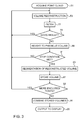
- Fig. 3 is a flow chart of a method for 3-dimensional anatomical reconstruction from a point cloud, in accordance with an embodiment of the invention.
- a point cloud of a structure e.g., the point cloud 42 ( Fig. 3 ) of a heart or portion thereof is acquired as described above, using the facilities of the system 10 ( Fig. 1 ) or an equivalent system.
- step 53 an initial volume reconstruction is prepared from the point cloud that was obtained in initial step 51. It should be noted that initial step 51 and step 53 may be performed in the same or different catheterization sessions.
- One way of performing step 53 is associating data 44 with the center of a corresponding volume element or voxel (not shown) and performing the process steps described below.
- Fig. 4 is a series of diagrams illustrating stages in a volume reconstruction from a point cloud, in accordance with an embodiment of the invention.
- the processor 22 uses a mapping module to initially connect locations 57 of the point cloud, e.g., data 44 ( Fig. 3 ) to define a mesh 61 of line segments 59,
- the mesh 61 typically, although not necessarily, is a triangular mesh.
- the processor 22 uses the Ball-Pivoting Algorithm (BPA) to produce the mesh 61.
- BPA Ball-Pivoting Algorithm
- a size of the ball is set to correspond to the size of the voxels referred to above.
- the mesh 61 may be generated as a Delaunay triangulation, comprising a plurality of triangles having vertices corresponding to the locations 57.
- the triangles of the triangulation may be based on Voronoi diagrams formed about the locations 57.
- the processor 22 may use any convenient method that is known in the art for forming a mesh.
- the processor 22 After producing the mesh 61, the processor 22 generates a generally smooth surface 63 connecting locations 57 and line segments 59. To generate the surface 63, the processor 22 typically uses interpolation and additionally or alternatively extrapolation. In addition, to ensure that the surface 63 is generally smooth, the processor 22 may adjust the surface to be close to, but not necessarily include, some of the locations 57 and line segments 59. By way of example, the surface 63 has contours 65, 67, 69.
- the processor 22 checks if the surface is closed, i.e., if the surface is topologically equivalent to a closed surface such as a sphere.
- surface 63 is not closed, having one or more openings.
- the openings in surface 108 may represent structures that naturally occur in the organ, such as the superior vena cava, or the inferior vena cava of the right atrium. Such openings are herein referred to as natural openings. Additionally, there may be openings in surface 63, herein referred to as artificial openings, because the organ has not been fully mapped.
- the processor 22 closes the surface by adding further surface elements until the surface is closed.
- the surface produced by closing surface 63 is herein referred to as closed surface 71.
- an opening is closed by adding an oriented bounding box that surrounds the opening, the box having a minimal volume. The box is then treated as part of the surface.
- the volume 73 ( Fig. 4 ) is subjected to a set of filter functions F. Some of the filter functions F may be applied to the mesh 61 and others to the volume 73.
- An exemplary list of filter functions follows:
- a Mixed is the mixed area in the mesh about the vertex x i .
- the discrete Gaussian curvature K is described in the publication Discrete Differential-Geometry Operators for Triangulated 2-Manifolds, Mark Meyer et al., International Workshop on Visualization and Mathematics (2002 ), which is herein incorporated by reference.
- delta K refers to changes in the Gaussian curvature K in successive mesh segmentations. This gives an indication of the smoothness of the mesh.
- all the filters F should be used. However, in some applications subsets of the filters F may be sufficient, and are economical of computer resources. Various subsets of the filters F may be chosen in different iterations of step 77. The subsets may be chosen according to an empirically developed order in order to most rapidly improve the mesh in various cardiac applications. Alternatively, the subsets may be chosen randomly or directed by the operator. Further alternatively, the set of filters F may be treated as a search space and the subsets can be selected according to search strategies, and methods known in the art of optimization.
- the subsets could be chosen in the following order: ⁇ f1, f2, f3, f5 ⁇ , ⁇ f1, f2, f3 ⁇ , ⁇ f1, f2, f5 ⁇ , ⁇ f1, f2 ⁇ , ⁇ f1, f2, f3, f4, f5 ⁇ , ⁇ f1, f2, f3, f4 ⁇ , ⁇ f1, f2, f4, f5 ⁇ , and ⁇ f1, f2, f4 ⁇ .
- the choice of sets may be automatically established in any given iteration according to progress made in previous iterations of step 77.In general, the quality of the results correlates with the number of filters used.
- step 79 it is determined whether the mesh at its current resolution is a "good mesh", i.e., (1) the mesh meets some predetermined criterion or has a predetermined quality, and (2) the current mesh has a higher resolution than in the last iteration.
- Each of the filters F has its own figure of merit, indicating the quality of the result.
- the criteria to be applied in evaluating the results of the filters are application dependent, and is accordingly selected by the user. For example, a combined figure of merit may be developed. Alternatively, the results of a minimum set of the filters F should meet or exceed their respective criteria. Many combinations of respective criteria for the filters F may be established. Regarding the Gaussian curvature, a choice of values between 2 * PI and 1.5 * PI is typical. In another example, for the Genus value filter (Euler's method), a choice of 0 is typical.
- the quality of the results correlates with the number of filters employed.
- step 79 If the determination at decision step 79 is affirmative, then, in order to attempt to obtain an even better resolution control returns to step 53, which is performed referring to a subset of the raw point cloud that is associated with the segmented portion currently in progress, to reconstruct a volume and iterate the filtering operations described above.
- step 53 which is performed referring to a subset of the raw point cloud that is associated with the segmented portion currently in progress, to reconstruct a volume and iterate the filtering operations described above.
- additional interpolated points on the surface 63 may be included among the locations 57.
- step 89 the current reconstructed value is discarded, and the method continues, using the result of the previous iteration.
- Typical stop conditions include failure to progress in a predetermined number of iterations, expiration of a preset time interval or completion of a predetermined number of iterations.
- step 83 segmentation of the reconstructed volume is performed in step 83.
- the segmentation algorithm does not require operator interaction to identify segments of the heart.
- the Plumber algorithm involving shape segmentation into tubular parts is suitable for use in step 83. This algorithm is described in the document Mesh segmentation - A Comparative Study, M. Attene et al., Proceedings of the IEEE International Conference on Shape Modeling and Applications 2006 , which is herein incorporated by reference. Other segmentation algorithms known in the art may also be used.
- the current segmented volume represents the best result attained thus far. It is stored at step 87.
- step 93 it is determined if enclosed points remain to be processed. If the determination is affirmative, then control returns to step 53. It is desirable to iterate the steps beginning with step 53 using different enclosed points in the mesh and corresponding portions of the raw point cloud (rather than the entire point cloud as in the first iteration).
- step 91 If the determination at decision step 93 is negative, then control proceeds to step 91.
- the volumes stored in step 87 are now combined into a single composite mesh. This step may be accomplished using the teachings of commonly assigned Application Serial No. 13/669,511, entitled “Combining Three-Dimensional Surfaces", whose disclosure is herein incorporated by reference.
- the combined surface provides a more complete 3-dimensional model than any of the individual meshes, without loss of accuracy.
- step 91 the composite mesh is output to a display at final step 85.
Abstract
Description
- This invention relates to medical imaging. More particularly, this invention relates to reconstruction of an anatomic structure from relatively sparse data.
- Medical catheterizations are routinely carried out today, for example, in cases of cardiac arrhythmias, such as atrial fibrillation, which occur when regions of cardiac tissue abnormally conduct electric signals to adjacent tissue, thereby disrupting the normal cardiac cycle and causing asynchronous rhythm. Procedures for treating arrhythmia include surgically disrupting the origin of the signals causing the arrhythmia, as well as disrupting the conducting pathway for such signals. By selectively ablating cardiac tissue by application of energy, e.g., radiofrequency energy via a catheter, it is sometimes possible to cease or modify the propagation of unwanted electrical signals from one portion of the heart to another. The ablation process destroys the unwanted electrical pathways by formation of non-conducting lesions. It is desirable in such procedures to provide a convenient representations of the cardiac anatomy to the operator.
- For example, the left atrium is a complicated 3-dimensional structure, the walls of which have dimensions, which differ from person to person, although all left atria have the same underlying shape. The left atrium can be divided into a number of substructures, such as the pulmonary vein, the mitral or bicuspid valve and the septum, which are conceptually easy to identify. The sub-structures also typically differ from person to person, but as for the overall left atrium, each substructure has the same underlying shape. In addition, a given substructure has the same relationship to the other substructures of the heart, regardless of the individual differences in shapes of the substructures.
- A collection of sparse data, known as a "point cloud", typically associated with a coordinate system, may be produced by imaging systems during a medical catheterization. Disclosed herein are methods and systems for developing a feature-rich 3-dimensional reconstruction of an anatomic structure from a point cloud, e.g., a point cloud obtained from a heart or portion thereof. The point cloud may be relatively sparse.
- When using a point cloud to reconstruct a 3D model of the heart, there is a question of an appropriate resolution of the reconstruction. A low resolution gives a rough reconstruction but works well with low-density point clouds. A high resolution gives a much more feature rich reconstruction, but is more prone to errors when applied to low density point clouds (holes and disconnected floating elements). This can be overcome by manually setting separate resolutions for separate regions of the reconstruction. However, the manual process is uncomfortable and takes some time. An automatic approach is preferable.
- There is provided according to embodiments of the invention a method of 3-dimensional cardiac reconstruction, which is carried out by inserting a probe into a heart of a living subject, the probe has a mapping electrode, urging the mapping electrode into contacting relationships with a tissue in plurality of regions of interest of the heart, acquiring electrical data from respective locations in the regions of interest, representing the locations of the electrical data as a point cloud, reconstructing a model of the heart from the point cloud, applying a set of filters to the model to produce a filtered volume, segmenting the filtered volume to define components of the heart, and reporting the segmented filtered volume, wherein at least one of the above steps is implemented in computer hardware or computer software embodied in a non-transitory computer-readable storage medium.
- In an aspect of the method, reconstructing a model and applying a set of filters are performed iteratively using portions of the point cloud until a stop condition is met. The stop condition may include one of a failure to achieve a progressively higher resolution of the filtered volume in a predetermined number of iterations, an expiration of a preset time interval and a completion of a predetermined number of iterations.
- According to an additional aspect of the method, applying a set of filters includes applying respective subsets of the set of filters in successive iterations thereof.
- According to yet another aspect of the method, the subsets are chosen randomly.
- According to still another aspect of the method, the subsets are chosen according to a search strategy.
- According to a further aspect of the method, applying a set of filters includes making a determination that the filtered volume has a resolution that exceeds a resolution of the filtered volume of a preceding iteration of applying a set of filters, and responsively to the determination, using the filtered volume as an input to a subsequent iteration of reconstructing a model and applying a set of filters.
- A further aspect of the method is carried out after segmenting the filtered volume by storing respective instances of the segmented filtered volume, and combining the instances of the segmented filtered volume into a composite volume, and displaying the composite volume.
- There is further provided according to embodiments of the invention an apparatus for carrying out the above-described method.
- For a better understanding of the present invention, reference is made to the detailed description of the invention, by way of example, which is to be read in conjunction with the following drawings, wherein like elements are given like reference numerals, and wherein:
-
Fig. 1 is a pictorial illustration of a system for catheterizing a heart of a living subject, which is constructed and operative in accordance with an embodiment of the invention; -
Fig. 2 is an illustration of a sparse point cloud aof | cardiac data obtained from respective locations in accordance with an embodiment of the invention; -
Fig. 3 is a flow chart of a method for 3-dimensional anatomical reconstruction from a point cloud, in accordance with an embodiment of the invention; and -
Fig. 4 is a series of diagrams illustrating stages in a volume reconstruction from a point cloud, in accordance with an embodiment of the invention. - In the following description, numerous specific details are set forth in order to provide a thorough understanding of the various principles of the present invention. It will be apparent to one skilled in the art, however, that not all these details are necessarily always needed for practicing the present invention. In this instance, well-known circuits, control logic, and the details of computer program instructions for conventional algorithms and processes have not been shown in detail in order not to obscure the general concepts unnecessarily.
- Aspects of the present invention may be embodied in software programming code, which is typically maintained in permanent storage, such as a computer readable medium. In a client/server environment, such software programming code may be stored on a client or a server. The software programming code may be embodied on any of a variety of known non-transitory media for use with a data processing system, such as a diskette, hard drive, electronic media or CD-ROM. The code may be distributed on such media, or may be distributed to users from the memory or storage of one computer system over a network of some type to storage devices on other computer systems for use by users of such other systems.
- Turning now to the drawings, reference is initially made to
Fig. 1 , which is a pictorial illustration of asystem 10 for performing diagnostic and therapeutic procedures on aheart 12 of a living subject, which is constructed and operative in accordance with an embodiment of the invention. The system comprises acatheter 14, which is percutaneously inserted by anoperator 16 through the patient's vascular system into a chamber or vascular structure of theheart 12. Theoperator 16, who is typically a physician, brings the catheter'sdistal tip 18 into contact with the heart wall at an ablation target site. Optionally, electrical activation maps may then be prepared, according to the methods disclosed inU.S. Patent Nos. 6,226,542 , and6,301,496 , and in commonly assignedU.S. Patent No. 6,892,091 , whose disclosures are herein incorporated by reference. One commercial product embodying elements of thesystem 10 is available as the CARTO® 3 System, available from Biosense Webster, Inc., 3333 Diamond Canyon Road, Diamond Bar, CA 91765. This system may be modified by those skilled in the art to embody the principles of the invention described herein. - Areas determined to be abnormal, for example by evaluation of the electrical activation maps, can be ablated by application of thermal energy, e.g., by passage of radiofrequency electrical current through wires in the catheter to one or more electrodes at the
distal tip 18, which apply the radiofrequency energy to the myocardium. The energy is absorbed in the tissue, heating it to a point (typically about 50°C) at which it permanently loses its electrical excitability. When successful, this procedure creates non-conducting lesions in the cardiac tissue, which disrupt the abnormal electrical pathway causing the arrhythmia. The principles of the invention can be applied to different heart chambers to treat many different cardiac arrhythmias. - The
catheter 14 typically comprises ahandle 20, having suitable controls on the handle to enable theoperator 16 to steer, position and orient the distal end of the catheter as desired for the ablation. To aid theoperator 16, the distal portion of thecatheter 14 contains position sensors (not shown) that provide signals to aprocessor 22, located in aconsole 24. - Ablation energy and electrical signals can be conveyed to and from the
heart 12 through one ormore ablation electrodes 32 located at or near thedistal tip 18 viacable 34 to theconsole 24. Pacing signals and other control signals may be conveyed from theconsole 24 through thecable 34 and theelectrodes 32 to theheart 12. Sensingelectrodes 33, also connected to theconsole 24, are disposed between theablation electrodes 32 and have connections to thecable 34. -
Wire connections 35 link theconsole 24 withbody surface electrodes 30 and other components of a positioning sub-system. Theelectrodes 32 and thebody surface electrodes 30 may be used to measure tissue impedance at the ablation site as taught inU.S. Patent No. 7,536,218 , issued to Govari et al., which is herein incorporated by reference. A temperature sensor such asthermocouples 31, may be mounted on or near theablation electrode 32 and optionally or near thesensing electrode 33. - The
console 24 typically contains one or moreablation power generators 25. Thecatheter 14 may be adapted to conduct ablative energy to the heart using any known ablation technique, e.g., radiofrequency energy, ultrasound energy, and laser-produced light energy. Such methods are disclosed in commonly assignedU.S. Patent Nos. 6,814,733 ,6,997,924 , and7,156,816 , which are herein incorporated by reference. - The
processor 22 functions as an element of a positioning subsystem in thesystem 10 that measures location and orientation coordinates of thecatheter 14. Theprocessor 22 has additional image processing functions, which are described in further detail hereinbelow. - In one embodiment, the positioning subsystem comprises a magnetic position tracking arrangement that determines the position and orientation of the
catheter 14 by generating magnetic fields in a predefined working volume and sensing these fields at the catheter, using field generating coils 28. The positioning subsystem may employ impedance measurement, as taught, for example inU.S. Patent No. 7,756,576 , which is hereby incorporated by reference, and in the above-notedU.S. Patent No. 7,536,218 . - As noted above, the
catheter 14 is coupled to theconsole 24, which enables theoperator 16 to observe and regulate the functions of thecatheter 14.Console 24 includes a processor, preferably a computer with appropriate signal processing circuits. The processor is coupled to drive amonitor 29. The signal processing circuits typically receive, amplify, filter and digitize signals from thecatheter 14, including signals generated by the above-noted sensors and a plurality of location sensing electrodes (not shown) located distally in thecatheter 14. The digitized signals are received and used by theconsole 24 and the positioning system to compute the position and orientation of thecatheter 14, and to analyze the electrical signals from the electrodes. - Typically, the
system 10 includes other elements, which are not shown in the figures for the sake of simplicity. For example, thesystem 10 may include an electrocardiogram (ECG) monitor, coupled to receive signals from one or more body surface electrodes, to provide an ECG synchronization signal to theconsole 24. As mentioned above, thesystem 10 typically also includes a reference position sensor, either on an externally-applied reference patch attached to the exterior of the subject's body, or on an internally-placed catheter, which is inserted into theheart 12 maintained in a fixed position relative to theheart 12. Conventional pumps and lines for circulating liquids through thecatheter 14 for cooling the ablation site are provided. - Reference is now made to
Fig. 2 , which is an illustration of asparse point cloud 42 of cardiac data obtained from respective locations in accordance with an embodiment of the invention. Such a point cloud may be acquired by ultrasound imaging of a chamber of a heart. Alternatively, the locations ofdata 44 are reported by a location sensor on the catheter, as known in the art. For example, sparse data may be acquired using the fast anatomic mapping (FAM) functions of the CARTO® 3 System cooperatively with a mapping catheter such as the Navistar® Thermocool® catheter, both available from Biosense Webster, Inc., 3333 Diamond Canyon Road, Diamond Bar, CA 91765. Processors such as are found in the CARTO system may be programmed to carry out the functions described below by those skilled in the art. - The
data 44 may be associated with respective coordinates in a 3-dimensional space, based on anatomic landmarks or fiducial marks, using location information provided bylocation sensors 46 on a catheter 48 as shown inFig. 2 . The location information may be described with 6 degrees of freedom. - Reference is now made to
Fig. 3 , which is a flow chart of a method for 3-dimensional anatomical reconstruction from a point cloud, in accordance with an embodiment of the invention. Atinitial step 51, a point cloud of a structure, e.g., the point cloud 42 (Fig. 3 ) of a heart or portion thereof is acquired as described above, using the facilities of the system 10 (Fig. 1 ) or an equivalent system. - Next, at
step 53 an initial volume reconstruction is prepared from the point cloud that was obtained ininitial step 51. It should be noted thatinitial step 51 and step 53 may be performed in the same or different catheterization sessions. One way of performingstep 53 is associatingdata 44 with the center of a corresponding volume element or voxel (not shown) and performing the process steps described below. - Reference is now made to
Fig. 4 , which is a series of diagrams illustrating stages in a volume reconstruction from a point cloud, in accordance with an embodiment of the invention. The processor 22 (Fig. 1 ) uses a mapping module to initially connectlocations 57 of the point cloud, e.g., data 44 (Fig. 3 ) to define amesh 61 ofline segments 59, - The
mesh 61 typically, although not necessarily, is a triangular mesh. In one embodiment, theprocessor 22 uses the Ball-Pivoting Algorithm (BPA) to produce themesh 61. Typically, if the BPA is used, a size of the ball is set to correspond to the size of the voxels referred to above. Alternatively, themesh 61 may be generated as a Delaunay triangulation, comprising a plurality of triangles having vertices corresponding to thelocations 57. The triangles of the triangulation may be based on Voronoi diagrams formed about thelocations 57. However, theprocessor 22 may use any convenient method that is known in the art for forming a mesh. - After producing the
mesh 61, theprocessor 22 generates a generallysmooth surface 63 connectinglocations 57 andline segments 59. To generate thesurface 63, theprocessor 22 typically uses interpolation and additionally or alternatively extrapolation. In addition, to ensure that thesurface 63 is generally smooth, theprocessor 22 may adjust the surface to be close to, but not necessarily include, some of thelocations 57 andline segments 59. By way of example, thesurface 63 hascontours - Then, after generating
surface 63, theprocessor 22 checks if the surface is closed, i.e., if the surface is topologically equivalent to a closed surface such as a sphere. Typically,surface 63 is not closed, having one or more openings. The openings in surface 108 may represent structures that naturally occur in the organ, such as the superior vena cava, or the inferior vena cava of the right atrium. Such openings are herein referred to as natural openings. Additionally, there may be openings insurface 63, herein referred to as artificial openings, because the organ has not been fully mapped. - In the event that surface 63 is not closed, the
processor 22 closes the surface by adding further surface elements until the surface is closed. The surface produced by closingsurface 63 is herein referred to as closedsurface 71. In one embodiment, an opening is closed by adding an oriented bounding box that surrounds the opening, the box having a minimal volume. The box is then treated as part of the surface. - The
closed surface 71 is assumed to have a defining equation:
- where S1 is a function. The
closed surface 71 encloses avolume 73 comprisingvoxels 75.Volume 73 is also referred to herein as volume V1, which may be defined as follows:
where V(x, y, z)represents a voxel centered on (x, y, z), and V1 is the volume formed by thevoxels 75. - Returning to
Fig. 3 , the process continues withstep 77. The volume 73 (Fig. 4 ) is subjected to a set of filter functions F. Some of the filter functions F may be applied to themesh 61 and others to thevolume 73. An exemplary list of filter functions follows: - f1: Given a mesh, calculate a mesh genus G, according to Euler's Graph invariant characteristic χ, which is well known in the field of algebraic topology, and return whether G == 1. If not, there is a hole in the mesh.
- f2: Given a mesh, find how many (n) well-connected elements there are and return whether n == 1. If not the mesh is composed of at least two separated elements. This is inconsistent with an anatomic structure, which would correspond to a mesh having one element, i.e., a single connected mesh.
- f3: Given a mesh find the vertices with the maximal discrete Gaussian curvature K in the reconstructed mesh. The Gaussian curvature K may be computed using the Gaussian curvature operator

where θj is the angle of the j th face at the vertex xi, and #f denotes the number of faces around the vertex xi. AMixed is the mixed area in the mesh about the vertex xi. - The discrete Gaussian curvature K is described in the publication Discrete Differential-Geometry Operators for Triangulated 2-Manifolds, Mark Meyer et al., International Workshop on Visualization and Mathematics (2002), which is herein incorporated by reference.
- Then determine whether max delta K is less than a specified threshold, wherein delta K refers to changes in the Gaussian curvature K in successive mesh segmentations. This gives an indication of the smoothness of the mesh.
- f4: For a given mesh compute its skeleton, and check to see if it is without junctions. The presence of junctions indicates that a mesh has appendages, and so needs further iterations of segmentation. Methods for building a mesh skeleton graph are known, for example, from the document Skeleton Extraction by Mesh Contraction, Oscar Kin-Chung Au et al., ACM Trans. on Graph, vol. 27, no. 3, pp. 44:1-44:10, 2008.
- f5: Run the segmentation algorithms S that are tube oriented (in order to find cylindrical elements), and see if the number of elements is equal or greater or equal to a specified number. Hierarchical body segmentation algorithms are suitable for example, as taught in the document Mesh Segmentation Using Feature Point and Core Extraction, Sagi Katz et al., The Visual Computer, Vol. 21, No. 8-10. (September 2005), pp. 649-658, which is herein incorporated by reference.
- Preferably, all the filters F should be used. However, in some applications subsets of the filters F may be sufficient, and are economical of computer resources. Various subsets of the filters F may be chosen in different iterations of
step 77. The subsets may be chosen according to an empirically developed order in order to most rapidly improve the mesh in various cardiac applications. Alternatively, the subsets may be chosen randomly or directed by the operator. Further alternatively, the set of filters F may be treated as a search space and the subsets can be selected according to search strategies, and methods known in the art of optimization. For example, the subsets could be chosen in the following order: {f1, f2, f3, f5}, {f1, f2, f3}, {f1, f2, f5}, {f1, f2}, {f1, f2, f3, f4, f5}, {f1, f2, f3, f4}, {f1, f2, f4, f5}, and {f1, f2, f4}. The choice of sets may be automatically established in any given iteration according to progress made in previous iterations of step 77.In general, the quality of the results correlates with the number of filters used. - Next, at
decision step 79, it is determined whether the mesh at its current resolution is a "good mesh", i.e., (1) the mesh meets some predetermined criterion or has a predetermined quality, and (2) the current mesh has a higher resolution than in the last iteration. - Each of the filters F has its own figure of merit, indicating the quality of the result. The criteria to be applied in evaluating the results of the filters are application dependent, and is accordingly selected by the user. For example, a combined figure of merit may be developed. Alternatively, the results of a minimum set of the filters F should meet or exceed their respective criteria. Many combinations of respective criteria for the filters F may be established. Regarding the Gaussian curvature, a choice of values between 2 * PI and 1.5 * PI is typical. In another example, for the Genus value filter (Euler's method), a choice of 0 is typical.
- Generally, the quality of the results correlates with the number of filters employed.
- If the determination at
decision step 79 is affirmative, then, in order to attempt to obtain an even better resolution control returns to step 53, which is performed referring to a subset of the raw point cloud that is associated with the segmented portion currently in progress, to reconstruct a volume and iterate the filtering operations described above. Optionally, additional interpolated points on thesurface 63 may be included among thelocations 57. - If the determination at
decision step 79 is negative, then atstep 89 the current reconstructed value is discarded, and the method continues, using the result of the previous iteration. - Control next proceeds to
decision step 81, where it is determined if a stop condition has been met. If not, then control returns to step 53 in order to improve the quality of the current reconstructed volume. Typical stop conditions include failure to progress in a predetermined number of iterations, expiration of a preset time interval or completion of a predetermined number of iterations. - If a stop condition has not been met in
decision step 81, then segmentation of the reconstructed volume is performed instep 83. The segmentation algorithm does not require operator interaction to identify segments of the heart. The Plumber algorithm involving shape segmentation into tubular parts is suitable for use instep 83. This algorithm is described in the document Mesh segmentation - A Comparative Study, M. Attene et al., Proceedings of the IEEE International Conference on Shape Modeling and Applications 2006, which is herein incorporated by reference. Other segmentation algorithms known in the art may also be used. - The current segmented volume represents the best result attained thus far. It is stored at
step 87. - At
decision step 93, it is determined if enclosed points remain to be processed. If the determination is affirmative, then control returns to step 53. It is desirable to iterate the steps beginning withstep 53 using different enclosed points in the mesh and corresponding portions of the raw point cloud (rather than the entire point cloud as in the first iteration). - If the determination at
decision step 93 is negative, then control proceeds to step 91. The volumes stored instep 87 are now combined into a single composite mesh. This step may be accomplished using the teachings of commonly assigned Application Serial No. 13/669,511, entitled "Combining Three-Dimensional Surfaces", whose disclosure is herein incorporated by reference. The combined surface provides a more complete 3-dimensional model than any of the individual meshes, without loss of accuracy. - Upon completion of
step 91, the composite mesh is output to a display atfinal step 85. - It will be appreciated by persons skilled in the art that the present invention is not limited to what has been particularly shown and described hereinabove. Rather, the scope of the present invention includes both combinations and subcombinations of the various features described hereinabove, as well as variations and modifications thereof that are not in the prior art, which would occur to persons skilled in the art upon reading the foregoing description.
- Aspects of the invention not yet claimed:
- Aspect 1. A method, comprising the steps of:
- inserting a probe into a heart of a living subject, the probe having a mapping electrode;
- urging the mapping electrode into contacting relationships with a tissue in plurality of regions of interest of the heart;
- acquiring electrical data from respective locations in the regions of interest;
- representing the locations of the electrical data as a point cloud;
- reconstructing a model of the heart from the point cloud;
- applying a set of filters to the model to produce a filtered volume;
- segmenting the filtered volume to define components of the heart; and
- reporting the segmented filtered volume, wherein at least one of the above steps is implemented in computer hardware or computer software embodied in a non-transitory computer-readable storage medium.
- Aspect 2. The method according to aspect 1, wherein the steps of reconstructing a model and applying a set of filters are performed iteratively using portions of the point cloud until a stop condition is met.
- Aspect 3. The method according to aspect 2, wherein applying a set of filters comprises applying respective subsets of the set of filters in successive iterations thereof.
- Aspect 4. The method according to aspect 3, wherein the subsets are chosen randomly.
- Aspect 5. The method according to aspect 3, wherein the subsets are chosen according to a search strategy.
- Aspect 6. The method according to aspect 2, wherein the stop condition comprises one of a failure to achieve a progressively higher resolution of the filtered volume in a predetermined number of iterations, an expiration of a preset time interval and a completion of a predetermined number of iterations.
- Aspect 7. The method according to aspect 2, wherein applying a set of filters comprises:
- making a determination that the filtered volume has a resolution that exceeds a resolution of the filtered volume of a preceding iteration of applying a set of filters; and
- responsively to the determination, using the filtered volume as an input to a subsequent iteration of the steps of reconstructing a model and applying a set of filters.
- Aspect 8. The method according to aspect 7, further comprising the steps of:
- after performances of the step of segmenting the filtered volume storing respective instances of the segmented filtered volume; and
- combining the instances of the segmented filtered volume into a composite volume, wherein displaying the segmented filtered volume comprises displaying the composite volume.
Claims (8)
- An apparatus, comprising:a probe adapted for insertion into contact with a heart in a body of a subject, the probe having a location sensor and an electrode on a distal portion of the probe;a processor linked to the location sensor, and operative performing the steps of:accepting electrical data from the electrode when the probe is in respective locations in regions of interest in the heart;representing the locations of the electrical data as a point cloud;reconstructing a model of the heart from the point cloud;applying a set of filters to the model to produce a filtered volume;segmenting the filtered volume to define components of the heart; andreporting the segmented filtered volume.
- The apparatus according to claim 1, wherein the steps of reconstructing a model and applying a set of filters are performed iteratively using portions of the point cloud until a stop condition is met.
- The apparatus according to claim 2, wherein applying a set of filters comprises applying respective subsets of the set of filters in successive iterations thereof.
- The apparatus according to claim 3, wherein the subsets are chosen randomly.
- The apparatus according to claim 3, wherein the subsets are chosen according to a search strategy.
- The apparatus according to claim 2, wherein the stop condition comprises one of a failure to achieve a progressively higher resolution of the filtered volume in a predetermined number of iterations, an expiration of a preset time interval and a completion of a predetermined number of iterations.
- The apparatus according to claim 2, wherein applying a set of filters comprises:making a determination that the filtered volume has a resolution that exceeds a resolution of the filtered volume of a preceding iteration of applying a set of filters; andresponsively to the determination, using the filtered volume as an input to a subsequent iteration of the steps of reconstructing a model and applying a set of filters.
- The apparatus according to claim 7, further comprising a display, wherein the processor is operative to perform the additional steps of:after performances of the step of segmenting the filtered volume storing respective instances of the segmented filtered volume; andcombining the instances of the segmented filtered volume into a composite volume, wherein reporting the segmented filtered volume comprises presenting the composite volume on the display.
Applications Claiming Priority (1)
| Application Number | Priority Date | Filing Date | Title |
|---|---|---|---|
| US14/132,631 US9265434B2 (en) | 2013-12-18 | 2013-12-18 | Dynamic feature rich anatomical reconstruction from a point cloud |
Publications (2)
| Publication Number | Publication Date |
|---|---|
| EP2886047A1 true EP2886047A1 (en) | 2015-06-24 |
| EP2886047B1 EP2886047B1 (en) | 2020-05-13 |
Family
ID=52344946
Family Applications (1)
| Application Number | Title | Priority Date | Filing Date |
|---|---|---|---|
| EP14198635.6A Active EP2886047B1 (en) | 2013-12-18 | 2014-12-17 | Dynamic feature rich anatomical reconstruction from a point cloud |
Country Status (7)
| Country | Link |
|---|---|
| US (1) | US9265434B2 (en) |
| EP (1) | EP2886047B1 (en) |
| JP (1) | JP6466159B2 (en) |
| CN (1) | CN104720888B (en) |
| AU (1) | AU2014274615B2 (en) |
| CA (1) | CA2874007A1 (en) |
| IL (1) | IL235564B (en) |
Families Citing this family (37)
| Publication number | Priority date | Publication date | Assignee | Title |
|---|---|---|---|---|
| US11389232B2 (en) | 2006-06-28 | 2022-07-19 | Kardium Inc. | Apparatus and method for intra-cardiac mapping and ablation |
| US9119633B2 (en) | 2006-06-28 | 2015-09-01 | Kardium Inc. | Apparatus and method for intra-cardiac mapping and ablation |
| US8906011B2 (en) | 2007-11-16 | 2014-12-09 | Kardium Inc. | Medical device for use in bodily lumens, for example an atrium |
| US8945117B2 (en) | 2009-02-11 | 2015-02-03 | Boston Scientific Scimed, Inc. | Insulated ablation catheter devices and methods of use |
| US10827977B2 (en) | 2012-05-21 | 2020-11-10 | Kardium Inc. | Systems and methods for activating transducers |
| US9017320B2 (en) | 2012-05-21 | 2015-04-28 | Kardium, Inc. | Systems and methods for activating transducers |
| US9198592B2 (en) | 2012-05-21 | 2015-12-01 | Kardium Inc. | Systems and methods for activating transducers |
| EP3074956B1 (en) * | 2014-03-21 | 2018-04-11 | St. Jude Medical, Cardiology Division, Inc. | Methods and systems for generating a multi-dimensional surface model of a geometric structure |
| KR102238693B1 (en) * | 2014-06-20 | 2021-04-09 | 삼성전자주식회사 | Method and apparatus for extracting feature regions in point cloud |
| EP3206612B1 (en) | 2014-10-13 | 2022-06-29 | Boston Scientific Scimed Inc. | Tissue diagnosis and treatment using mini-electrodes |
| WO2016065337A1 (en) | 2014-10-24 | 2016-04-28 | Boston Scientific Scimed Inc. | Medical devices with a flexible electrode assembly coupled to an ablation tip |
| US10368936B2 (en) | 2014-11-17 | 2019-08-06 | Kardium Inc. | Systems and methods for selecting, activating, or selecting and activating transducers |
| US10722184B2 (en) | 2014-11-17 | 2020-07-28 | Kardium Inc. | Systems and methods for selecting, activating, or selecting and activating transducers |
| US9743854B2 (en) | 2014-12-18 | 2017-08-29 | Boston Scientific Scimed, Inc. | Real-time morphology analysis for lesion assessment |
| WO2017099582A2 (en) * | 2015-10-21 | 2017-06-15 | Peacs B.V. | Heart condition determination method, robot control and system |
| US10588692B2 (en) | 2015-11-06 | 2020-03-17 | Biosense Webster (Israel) Ltd. | Pulmonary vein isolation gap finder |
| US10282888B2 (en) | 2016-01-28 | 2019-05-07 | Biosense Webster (Israel) Ltd. | High definition coloring of heart chambers |
| US10765329B2 (en) * | 2016-05-02 | 2020-09-08 | Topera, Inc. | System and method to define an aggregated stability map of a rotational source over a plurality of time intervals associated with a biological rhythm disorder |
| US11129574B2 (en) | 2016-12-12 | 2021-09-28 | Biosense Webster (Israel) Ltd. | Real time electroanatomical coloring of the heart |
| US10327851B2 (en) | 2016-12-13 | 2019-06-25 | Biosense Webster (Israel) Ltd. | Method and apparatus for ablation planning and control |
| US10398346B2 (en) | 2017-05-15 | 2019-09-03 | Florida Atlantic University Board Of Trustees | Systems and methods for localizing signal resources using multi-pole sensors |
| US11304603B2 (en) | 2017-08-21 | 2022-04-19 | Biosense Webster (Israel) Ltd. | Advanced current location (ACL) automatic map rotation to detect holes in current position map (CPM) mapping |
| US10682181B2 (en) | 2017-09-06 | 2020-06-16 | Biosense Webster (Israel) Ltd. | Methods and systems for modeling and registration of 3-dimensional images of the heart |
| US10398338B2 (en) | 2017-10-06 | 2019-09-03 | Florida Atlantic University Board Of Trustees | Systems and methods for guiding a multi-pole sensor catheter to locate cardiac arrhythmia sources |
| US10460512B2 (en) * | 2017-11-07 | 2019-10-29 | Microsoft Technology Licensing, Llc | 3D skeletonization using truncated epipolar lines |
| US10575746B2 (en) | 2017-12-14 | 2020-03-03 | Biosense Webster (Israel) Ltd. | Epicardial mapping |
| US10898093B2 (en) * | 2018-01-29 | 2021-01-26 | Biosense Webster (Israel) Ltd. | Scar assessment |
| WO2020008418A1 (en) * | 2018-07-04 | 2020-01-09 | Navix International Limited | Incorporating new location readings to old models |
| US20210174940A1 (en) * | 2018-07-04 | 2021-06-10 | Navix International Limited | Systems and methods for reconstruction of medical images |
| US11636650B2 (en) | 2018-09-24 | 2023-04-25 | K2M, Inc. | System and method for isolating anatomical features in computerized tomography data |
| US11478301B2 (en) * | 2018-11-15 | 2022-10-25 | Centerline Biomedical, Inc. | Modeling anatomical structures using an anatomical measurement wire |
| CN109528298B (en) * | 2018-11-30 | 2021-11-09 | 珠海市司迈科技有限公司 | Intelligent surgical device and working method thereof |
| US11393167B2 (en) | 2018-12-31 | 2022-07-19 | Biosense Webster (Israel) Ltd. | Volume rendering optimization with known transfer function |
| US10593112B1 (en) | 2019-04-15 | 2020-03-17 | Biosense Webster (Israel) Ltd. | Chamber reconstruction from a partial volume |
| US11607272B2 (en) * | 2019-11-12 | 2023-03-21 | Biosense Webster (Israel) Ltd. | Visual route indication for activation clusters |
| US11461895B2 (en) * | 2020-09-01 | 2022-10-04 | Biosense Webster (Israel) Ltd. | Automatic identification and processing of anatomical structures in an anatomical map |
| CN116129060B (en) * | 2023-04-18 | 2023-06-23 | 心航路医学科技(广州)有限公司 | Heart three-dimensional anatomical model construction method and heart three-dimensional mapping system |
Citations (11)
| Publication number | Priority date | Publication date | Assignee | Title |
|---|---|---|---|---|
| US6226542B1 (en) | 1998-07-24 | 2001-05-01 | Biosense, Inc. | Three-dimensional reconstruction of intrabody organs |
| US6301496B1 (en) | 1998-07-24 | 2001-10-09 | Biosense, Inc. | Vector mapping of three-dimensionally reconstructed intrabody organs and method of display |
| US6814733B2 (en) | 2002-01-31 | 2004-11-09 | Biosense, Inc. | Radio frequency pulmonary vein isolation |
| US6892091B1 (en) | 2000-02-18 | 2005-05-10 | Biosense, Inc. | Catheter, method and apparatus for generating an electrical map of a chamber of the heart |
| US6997924B2 (en) | 2002-09-17 | 2006-02-14 | Biosense Inc. | Laser pulmonary vein isolation |
| US7156816B2 (en) | 2002-11-26 | 2007-01-02 | Biosense, Inc. | Ultrasound pulmonary vein isolation |
| US20070299352A1 (en) * | 2006-06-13 | 2007-12-27 | Doron Harlev | Non-contact cardiac mapping, including moving catheter and multi-beat integration |
| US7536218B2 (en) | 2005-07-15 | 2009-05-19 | Biosense Webster, Inc. | Hybrid magnetic-based and impedance-based position sensing |
| US7756576B2 (en) | 2005-08-26 | 2010-07-13 | Biosense Webster, Inc. | Position sensing and detection of skin impedance |
| US20100274123A1 (en) * | 2006-05-17 | 2010-10-28 | Eric Jon Voth | System and method for mapping electrophysiology information onto complex geometry |
| US20130173222A1 (en) * | 2011-12-29 | 2013-07-04 | Eric J. Voth | Method and system for constructing an electrophysiology map |
Family Cites Families (12)
| Publication number | Priority date | Publication date | Assignee | Title |
|---|---|---|---|---|
| US7263397B2 (en) * | 1998-06-30 | 2007-08-28 | St. Jude Medical, Atrial Fibrillation Division, Inc. | Method and apparatus for catheter navigation and location and mapping in the heart |
| CN106725448B (en) * | 2006-05-17 | 2020-01-31 | 圣朱德医疗有限公司房颤分公司 | System and method for mapping electrophysiological information onto complex geometries |
| US7988639B2 (en) * | 2006-05-17 | 2011-08-02 | St. Jude Medical, Atrial Fibrillation Division, Inc. | System and method for complex geometry modeling of anatomy using multiple surface models |
| US7505810B2 (en) * | 2006-06-13 | 2009-03-17 | Rhythmia Medical, Inc. | Non-contact cardiac mapping, including preprocessing |
| US8437518B2 (en) * | 2006-08-08 | 2013-05-07 | Koninklijke Philips Electronics N.V. | Registration of electroanatomical mapping points to corresponding image data |
| ATE497729T1 (en) * | 2006-10-02 | 2011-02-15 | Hansen Medical Inc | SYSTEM FOR THREE-DIMENSIONAL ULTRASONIC IMAGING |
| US8000941B2 (en) * | 2007-12-30 | 2011-08-16 | St. Jude Medical, Atrial Fibrillation Division, Inc. | System and method for surface reconstruction from an unstructured point set |
| CN101667290B (en) | 2008-09-05 | 2012-12-19 | 鸿富锦精密工业(深圳)有限公司 | Method and computer system for fitting characteristic elements |
| US10835207B2 (en) * | 2009-12-23 | 2020-11-17 | Biosense Webster (Israel) Ltd. | Fast anatomical mapping using ultrasound images |
| DE102010018261B4 (en) * | 2010-04-26 | 2012-07-12 | Siemens Aktiengesellschaft | Method and computer system for automatic vectorization of a vascular tree |
| JP5492024B2 (en) * | 2010-08-30 | 2014-05-14 | 富士フイルム株式会社 | Region division result correction apparatus, method, and program |
| CN103021017B (en) * | 2012-12-04 | 2015-05-20 | 上海交通大学 | Three-dimensional scene rebuilding method based on GPU acceleration |
-
2013
- 2013-12-18 US US14/132,631 patent/US9265434B2/en active Active
-
2014
- 2014-11-06 IL IL235564A patent/IL235564B/en active IP Right Grant
- 2014-12-10 CA CA2874007A patent/CA2874007A1/en not_active Abandoned
- 2014-12-12 AU AU2014274615A patent/AU2014274615B2/en not_active Ceased
- 2014-12-17 EP EP14198635.6A patent/EP2886047B1/en active Active
- 2014-12-17 JP JP2014254841A patent/JP6466159B2/en active Active
- 2014-12-18 CN CN201410795593.5A patent/CN104720888B/en active Active
Patent Citations (11)
| Publication number | Priority date | Publication date | Assignee | Title |
|---|---|---|---|---|
| US6226542B1 (en) | 1998-07-24 | 2001-05-01 | Biosense, Inc. | Three-dimensional reconstruction of intrabody organs |
| US6301496B1 (en) | 1998-07-24 | 2001-10-09 | Biosense, Inc. | Vector mapping of three-dimensionally reconstructed intrabody organs and method of display |
| US6892091B1 (en) | 2000-02-18 | 2005-05-10 | Biosense, Inc. | Catheter, method and apparatus for generating an electrical map of a chamber of the heart |
| US6814733B2 (en) | 2002-01-31 | 2004-11-09 | Biosense, Inc. | Radio frequency pulmonary vein isolation |
| US6997924B2 (en) | 2002-09-17 | 2006-02-14 | Biosense Inc. | Laser pulmonary vein isolation |
| US7156816B2 (en) | 2002-11-26 | 2007-01-02 | Biosense, Inc. | Ultrasound pulmonary vein isolation |
| US7536218B2 (en) | 2005-07-15 | 2009-05-19 | Biosense Webster, Inc. | Hybrid magnetic-based and impedance-based position sensing |
| US7756576B2 (en) | 2005-08-26 | 2010-07-13 | Biosense Webster, Inc. | Position sensing and detection of skin impedance |
| US20100274123A1 (en) * | 2006-05-17 | 2010-10-28 | Eric Jon Voth | System and method for mapping electrophysiology information onto complex geometry |
| US20070299352A1 (en) * | 2006-06-13 | 2007-12-27 | Doron Harlev | Non-contact cardiac mapping, including moving catheter and multi-beat integration |
| US20130173222A1 (en) * | 2011-12-29 | 2013-07-04 | Eric J. Voth | Method and system for constructing an electrophysiology map |
Non-Patent Citations (4)
| Title |
|---|
| M. ATTENE ET AL.: "Mesh segmentation - A Comparative Study", PROCEEDINGS OF THE IEEE INTERNATIONAL CONFERENCE ON SHAPE MODELING AND APPLICATIONS, 2006 |
| MARK MEYER ET AL.: "Discrete Differential-Geometry Operators for Triangulated 2-Manifolds", INTERNATIONAL WORKSHOP ON VISUALIZATION AND MATHEMATICS, 2002 |
| OSCAR KIN-CHUNG AU ET AL.: "Skeleton Extraction by Mesh Contraction", ACM TRANS. ON GRAPH, vol. 27, no. 3, 2008, pages 44 - 1,44-10, XP058355353, DOI: doi:10.1145/1360612.1360643 |
| SAGI KATZ ET AL.: "Mesh Segmentation Using Feature Point and Core Extraction", THE VISUAL COMPUTER, vol. 21, no. 8-10, September 2005 (2005-09-01), pages 649 - 658, XP019339160, DOI: doi:10.1007/s00371-005-0344-9 |
Also Published As
| Publication number | Publication date |
|---|---|
| EP2886047B1 (en) | 2020-05-13 |
| JP6466159B2 (en) | 2019-02-06 |
| US20150164356A1 (en) | 2015-06-18 |
| AU2014274615B2 (en) | 2018-10-04 |
| IL235564B (en) | 2018-01-31 |
| US9265434B2 (en) | 2016-02-23 |
| AU2014274615A1 (en) | 2015-07-09 |
| CN104720888B (en) | 2019-10-18 |
| CN104720888A (en) | 2015-06-24 |
| CA2874007A1 (en) | 2015-06-18 |
| IL235564A0 (en) | 2015-02-26 |
| JP2015116488A (en) | 2015-06-25 |
Similar Documents
| Publication | Publication Date | Title |
|---|---|---|
| EP2886047B1 (en) | Dynamic feature rich anatomical reconstruction from a point cloud | |
| US11439337B2 (en) | Mapping of atrial fibrillation | |
| EP3453328B1 (en) | Mesh fitting algorithm | |
| US10403053B2 (en) | Marking sparse areas on maps | |
| CA2856035C (en) | Model based reconstruction of the heart from sparse samples | |
| US10342620B2 (en) | Efficient treatment of atrial fibrillation using three-dimensional electrical potential model | |
| US20200155230A1 (en) | Pulmonary vein isolation gap finder | |
| US10482198B2 (en) | Global mapping catheter contact optimization |
Legal Events
| Date | Code | Title | Description |
|---|---|---|---|
| PUAI | Public reference made under article 153(3) epc to a published international application that has entered the european phase |
Free format text: ORIGINAL CODE: 0009012 |
|
| 17P | Request for examination filed |
Effective date: 20141217 |
|
| AK | Designated contracting states |
Kind code of ref document: A1 Designated state(s): AL AT BE BG CH CY CZ DE DK EE ES FI FR GB GR HR HU IE IS IT LI LT LU LV MC MK MT NL NO PL PT RO RS SE SI SK SM TR |
|
| AX | Request for extension of the european patent |
Extension state: BA ME |
|
| R17P | Request for examination filed (corrected) |
Effective date: 20151223 |
|
| RBV | Designated contracting states (corrected) |
Designated state(s): AL AT BE BG CH CY CZ DE DK EE ES FI FR GB GR HR HU IE IS IT LI LT LU LV MC MK MT NL NO PL PT RO RS SE SI SK SM TR |
|
| STAA | Information on the status of an ep patent application or granted ep patent |
Free format text: STATUS: EXAMINATION IS IN PROGRESS |
|
| 17Q | First examination report despatched |
Effective date: 20180821 |
|
| GRAP | Despatch of communication of intention to grant a patent |
Free format text: ORIGINAL CODE: EPIDOSNIGR1 |
|
| STAA | Information on the status of an ep patent application or granted ep patent |
Free format text: STATUS: GRANT OF PATENT IS INTENDED |
|
| INTG | Intention to grant announced |
Effective date: 20200305 |
|
| GRAS | Grant fee paid |
Free format text: ORIGINAL CODE: EPIDOSNIGR3 |
|
| GRAA | (expected) grant |
Free format text: ORIGINAL CODE: 0009210 |
|
| STAA | Information on the status of an ep patent application or granted ep patent |
Free format text: STATUS: THE PATENT HAS BEEN GRANTED |
|
| RAP1 | Party data changed (applicant data changed or rights of an application transferred) |
Owner name: BIOSENSE WEBSTER (ISRAEL) LTD. |
|
| AK | Designated contracting states |
Kind code of ref document: B1 Designated state(s): AL AT BE BG CH CY CZ DE DK EE ES FI FR GB GR HR HU IE IS IT LI LT LU LV MC MK MT NL NO PL PT RO RS SE SI SK SM TR |
|
| REG | Reference to a national code |
Ref country code: GB Ref legal event code: FG4D |
|
| REG | Reference to a national code |
Ref country code: CH Ref legal event code: EP |
|
| REG | Reference to a national code |
Ref country code: DE Ref legal event code: R096 Ref document number: 602014065375 Country of ref document: DE |
|
| REG | Reference to a national code |
Ref country code: AT Ref legal event code: REF Ref document number: 1269129 Country of ref document: AT Kind code of ref document: T Effective date: 20200615 |
|
| REG | Reference to a national code |
Ref country code: NL Ref legal event code: FP |
|
| REG | Reference to a national code |
Ref country code: LT Ref legal event code: MG4D |
|
| PG25 | Lapsed in a contracting state [announced via postgrant information from national office to epo] |
Ref country code: IS Free format text: LAPSE BECAUSE OF FAILURE TO SUBMIT A TRANSLATION OF THE DESCRIPTION OR TO PAY THE FEE WITHIN THE PRESCRIBED TIME-LIMIT Effective date: 20200913 Ref country code: GR Free format text: LAPSE BECAUSE OF FAILURE TO SUBMIT A TRANSLATION OF THE DESCRIPTION OR TO PAY THE FEE WITHIN THE PRESCRIBED TIME-LIMIT Effective date: 20200814 Ref country code: NO Free format text: LAPSE BECAUSE OF FAILURE TO SUBMIT A TRANSLATION OF THE DESCRIPTION OR TO PAY THE FEE WITHIN THE PRESCRIBED TIME-LIMIT Effective date: 20200813 Ref country code: FI Free format text: LAPSE BECAUSE OF FAILURE TO SUBMIT A TRANSLATION OF THE DESCRIPTION OR TO PAY THE FEE WITHIN THE PRESCRIBED TIME-LIMIT Effective date: 20200513 Ref country code: LT Free format text: LAPSE BECAUSE OF FAILURE TO SUBMIT A TRANSLATION OF THE DESCRIPTION OR TO PAY THE FEE WITHIN THE PRESCRIBED TIME-LIMIT Effective date: 20200513 Ref country code: SE Free format text: LAPSE BECAUSE OF FAILURE TO SUBMIT A TRANSLATION OF THE DESCRIPTION OR TO PAY THE FEE WITHIN THE PRESCRIBED TIME-LIMIT Effective date: 20200513 Ref country code: PT Free format text: LAPSE BECAUSE OF FAILURE TO SUBMIT A TRANSLATION OF THE DESCRIPTION OR TO PAY THE FEE WITHIN THE PRESCRIBED TIME-LIMIT Effective date: 20200914 |
|
| PG25 | Lapsed in a contracting state [announced via postgrant information from national office to epo] |
Ref country code: BG Free format text: LAPSE BECAUSE OF FAILURE TO SUBMIT A TRANSLATION OF THE DESCRIPTION OR TO PAY THE FEE WITHIN THE PRESCRIBED TIME-LIMIT Effective date: 20200813 Ref country code: RS Free format text: LAPSE BECAUSE OF FAILURE TO SUBMIT A TRANSLATION OF THE DESCRIPTION OR TO PAY THE FEE WITHIN THE PRESCRIBED TIME-LIMIT Effective date: 20200513 Ref country code: HR Free format text: LAPSE BECAUSE OF FAILURE TO SUBMIT A TRANSLATION OF THE DESCRIPTION OR TO PAY THE FEE WITHIN THE PRESCRIBED TIME-LIMIT Effective date: 20200513 Ref country code: LV Free format text: LAPSE BECAUSE OF FAILURE TO SUBMIT A TRANSLATION OF THE DESCRIPTION OR TO PAY THE FEE WITHIN THE PRESCRIBED TIME-LIMIT Effective date: 20200513 |
|
| REG | Reference to a national code |
Ref country code: AT Ref legal event code: MK05 Ref document number: 1269129 Country of ref document: AT Kind code of ref document: T Effective date: 20200513 |
|
| PG25 | Lapsed in a contracting state [announced via postgrant information from national office to epo] |
Ref country code: AL Free format text: LAPSE BECAUSE OF FAILURE TO SUBMIT A TRANSLATION OF THE DESCRIPTION OR TO PAY THE FEE WITHIN THE PRESCRIBED TIME-LIMIT Effective date: 20200513 |
|
| PG25 | Lapsed in a contracting state [announced via postgrant information from national office to epo] |
Ref country code: AT Free format text: LAPSE BECAUSE OF FAILURE TO SUBMIT A TRANSLATION OF THE DESCRIPTION OR TO PAY THE FEE WITHIN THE PRESCRIBED TIME-LIMIT Effective date: 20200513 Ref country code: EE Free format text: LAPSE BECAUSE OF FAILURE TO SUBMIT A TRANSLATION OF THE DESCRIPTION OR TO PAY THE FEE WITHIN THE PRESCRIBED TIME-LIMIT Effective date: 20200513 Ref country code: SM Free format text: LAPSE BECAUSE OF FAILURE TO SUBMIT A TRANSLATION OF THE DESCRIPTION OR TO PAY THE FEE WITHIN THE PRESCRIBED TIME-LIMIT Effective date: 20200513 Ref country code: DK Free format text: LAPSE BECAUSE OF FAILURE TO SUBMIT A TRANSLATION OF THE DESCRIPTION OR TO PAY THE FEE WITHIN THE PRESCRIBED TIME-LIMIT Effective date: 20200513 Ref country code: CZ Free format text: LAPSE BECAUSE OF FAILURE TO SUBMIT A TRANSLATION OF THE DESCRIPTION OR TO PAY THE FEE WITHIN THE PRESCRIBED TIME-LIMIT Effective date: 20200513 Ref country code: ES Free format text: LAPSE BECAUSE OF FAILURE TO SUBMIT A TRANSLATION OF THE DESCRIPTION OR TO PAY THE FEE WITHIN THE PRESCRIBED TIME-LIMIT Effective date: 20200513 Ref country code: RO Free format text: LAPSE BECAUSE OF FAILURE TO SUBMIT A TRANSLATION OF THE DESCRIPTION OR TO PAY THE FEE WITHIN THE PRESCRIBED TIME-LIMIT Effective date: 20200513 |
|
| REG | Reference to a national code |
Ref country code: DE Ref legal event code: R097 Ref document number: 602014065375 Country of ref document: DE |
|
| PG25 | Lapsed in a contracting state [announced via postgrant information from national office to epo] |
Ref country code: SK Free format text: LAPSE BECAUSE OF FAILURE TO SUBMIT A TRANSLATION OF THE DESCRIPTION OR TO PAY THE FEE WITHIN THE PRESCRIBED TIME-LIMIT Effective date: 20200513 Ref country code: PL Free format text: LAPSE BECAUSE OF FAILURE TO SUBMIT A TRANSLATION OF THE DESCRIPTION OR TO PAY THE FEE WITHIN THE PRESCRIBED TIME-LIMIT Effective date: 20200513 |
|
| PLBE | No opposition filed within time limit |
Free format text: ORIGINAL CODE: 0009261 |
|
| STAA | Information on the status of an ep patent application or granted ep patent |
Free format text: STATUS: NO OPPOSITION FILED WITHIN TIME LIMIT |
|
| 26N | No opposition filed |
Effective date: 20210216 |
|
| PG25 | Lapsed in a contracting state [announced via postgrant information from national office to epo] |
Ref country code: SI Free format text: LAPSE BECAUSE OF FAILURE TO SUBMIT A TRANSLATION OF THE DESCRIPTION OR TO PAY THE FEE WITHIN THE PRESCRIBED TIME-LIMIT Effective date: 20200513 |
|
| REG | Reference to a national code |
Ref country code: CH Ref legal event code: PL |
|
| PG25 | Lapsed in a contracting state [announced via postgrant information from national office to epo] |
Ref country code: MC Free format text: LAPSE BECAUSE OF FAILURE TO SUBMIT A TRANSLATION OF THE DESCRIPTION OR TO PAY THE FEE WITHIN THE PRESCRIBED TIME-LIMIT Effective date: 20200513 |
|
| REG | Reference to a national code |
Ref country code: BE Ref legal event code: MM Effective date: 20201231 |
|
| PG25 | Lapsed in a contracting state [announced via postgrant information from national office to epo] |
Ref country code: LU Free format text: LAPSE BECAUSE OF NON-PAYMENT OF DUE FEES Effective date: 20201217 Ref country code: IE Free format text: LAPSE BECAUSE OF NON-PAYMENT OF DUE FEES Effective date: 20201217 |
|
| PG25 | Lapsed in a contracting state [announced via postgrant information from national office to epo] |
Ref country code: LI Free format text: LAPSE BECAUSE OF NON-PAYMENT OF DUE FEES Effective date: 20201231 Ref country code: CH Free format text: LAPSE BECAUSE OF NON-PAYMENT OF DUE FEES Effective date: 20201231 |
|
| PG25 | Lapsed in a contracting state [announced via postgrant information from national office to epo] |
Ref country code: TR Free format text: LAPSE BECAUSE OF FAILURE TO SUBMIT A TRANSLATION OF THE DESCRIPTION OR TO PAY THE FEE WITHIN THE PRESCRIBED TIME-LIMIT Effective date: 20200513 Ref country code: MT Free format text: LAPSE BECAUSE OF FAILURE TO SUBMIT A TRANSLATION OF THE DESCRIPTION OR TO PAY THE FEE WITHIN THE PRESCRIBED TIME-LIMIT Effective date: 20200513 Ref country code: CY Free format text: LAPSE BECAUSE OF FAILURE TO SUBMIT A TRANSLATION OF THE DESCRIPTION OR TO PAY THE FEE WITHIN THE PRESCRIBED TIME-LIMIT Effective date: 20200513 |
|
| PG25 | Lapsed in a contracting state [announced via postgrant information from national office to epo] |
Ref country code: MK Free format text: LAPSE BECAUSE OF FAILURE TO SUBMIT A TRANSLATION OF THE DESCRIPTION OR TO PAY THE FEE WITHIN THE PRESCRIBED TIME-LIMIT Effective date: 20200513 |
|
| PG25 | Lapsed in a contracting state [announced via postgrant information from national office to epo] |
Ref country code: BE Free format text: LAPSE BECAUSE OF NON-PAYMENT OF DUE FEES Effective date: 20201231 |
|
| PGFP | Annual fee paid to national office [announced via postgrant information from national office to epo] |
Ref country code: NL Payment date: 20221114 Year of fee payment: 9 |
|
| PGFP | Annual fee paid to national office [announced via postgrant information from national office to epo] |
Ref country code: GB Payment date: 20231102 Year of fee payment: 10 |
|
| PGFP | Annual fee paid to national office [announced via postgrant information from national office to epo] |
Ref country code: IT Payment date: 20231110 Year of fee payment: 10 Ref country code: FR Payment date: 20231108 Year of fee payment: 10 Ref country code: DE Payment date: 20231031 Year of fee payment: 10 |