EP2884247A1 - Spectrometer for generating a two dimensional spectrum - Google Patents
Spectrometer for generating a two dimensional spectrum Download PDFInfo
- Publication number
- EP2884247A1 EP2884247A1 EP13197479.2A EP13197479A EP2884247A1 EP 2884247 A1 EP2884247 A1 EP 2884247A1 EP 13197479 A EP13197479 A EP 13197479A EP 2884247 A1 EP2884247 A1 EP 2884247A1
- Authority
- EP
- European Patent Office
- Prior art keywords
- main
- spectrometer
- main grating
- grating
- image plane
- Prior art date
- Legal status (The legal status is an assumption and is not a legal conclusion. Google has not performed a legal analysis and makes no representation as to the accuracy of the status listed.)
- Withdrawn
Links
- 238000001228 spectrum Methods 0.000 title claims abstract description 51
- 238000003384 imaging method Methods 0.000 claims abstract description 78
- 230000005855 radiation Effects 0.000 claims abstract description 57
- 239000006185 dispersion Substances 0.000 claims abstract description 55
- 230000003287 optical effect Effects 0.000 claims abstract description 44
- 238000000034 method Methods 0.000 claims abstract description 28
- 230000004075 alteration Effects 0.000 claims abstract description 19
- 230000008859 change Effects 0.000 claims description 2
- 230000003595 spectral effect Effects 0.000 description 11
- 230000008901 benefit Effects 0.000 description 8
- 238000009826 distribution Methods 0.000 description 6
- 238000004519 manufacturing process Methods 0.000 description 4
- 230000001419 dependent effect Effects 0.000 description 3
- 230000000694 effects Effects 0.000 description 2
- 230000008569 process Effects 0.000 description 2
- 238000004458 analytical method Methods 0.000 description 1
- 230000005670 electromagnetic radiation Effects 0.000 description 1
- 238000012986 modification Methods 0.000 description 1
- 230000004048 modification Effects 0.000 description 1
- 239000000523 sample Substances 0.000 description 1
- 238000000926 separation method Methods 0.000 description 1
- 238000007493 shaping process Methods 0.000 description 1
- 238000003860 storage Methods 0.000 description 1
- 230000001052 transient effect Effects 0.000 description 1
Images

Classifications
-
- G—PHYSICS
- G01—MEASURING; TESTING
- G01J—MEASUREMENT OF INTENSITY, VELOCITY, SPECTRAL CONTENT, POLARISATION, PHASE OR PULSE CHARACTERISTICS OF INFRARED, VISIBLE OR ULTRAVIOLET LIGHT; COLORIMETRY; RADIATION PYROMETRY
- G01J3/00—Spectrometry; Spectrophotometry; Monochromators; Measuring colours
- G01J3/28—Investigating the spectrum
- G01J3/2823—Imaging spectrometer
-
- G—PHYSICS
- G01—MEASURING; TESTING
- G01J—MEASUREMENT OF INTENSITY, VELOCITY, SPECTRAL CONTENT, POLARISATION, PHASE OR PULSE CHARACTERISTICS OF INFRARED, VISIBLE OR ULTRAVIOLET LIGHT; COLORIMETRY; RADIATION PYROMETRY
- G01J3/00—Spectrometry; Spectrophotometry; Monochromators; Measuring colours
- G01J3/02—Details
- G01J3/0205—Optical elements not provided otherwise, e.g. optical manifolds, diffusers, windows
- G01J3/0208—Optical elements not provided otherwise, e.g. optical manifolds, diffusers, windows using focussing or collimating elements, e.g. lenses or mirrors; performing aberration correction
-
- G—PHYSICS
- G01—MEASURING; TESTING
- G01J—MEASUREMENT OF INTENSITY, VELOCITY, SPECTRAL CONTENT, POLARISATION, PHASE OR PULSE CHARACTERISTICS OF INFRARED, VISIBLE OR ULTRAVIOLET LIGHT; COLORIMETRY; RADIATION PYROMETRY
- G01J3/00—Spectrometry; Spectrophotometry; Monochromators; Measuring colours
- G01J3/02—Details
- G01J3/0205—Optical elements not provided otherwise, e.g. optical manifolds, diffusers, windows
- G01J3/021—Optical elements not provided otherwise, e.g. optical manifolds, diffusers, windows using plane or convex mirrors, parallel phase plates, or particular reflectors
-
- G—PHYSICS
- G01—MEASURING; TESTING
- G01J—MEASUREMENT OF INTENSITY, VELOCITY, SPECTRAL CONTENT, POLARISATION, PHASE OR PULSE CHARACTERISTICS OF INFRARED, VISIBLE OR ULTRAVIOLET LIGHT; COLORIMETRY; RADIATION PYROMETRY
- G01J3/00—Spectrometry; Spectrophotometry; Monochromators; Measuring colours
- G01J3/02—Details
- G01J3/0256—Compact construction
-
- G—PHYSICS
- G01—MEASURING; TESTING
- G01J—MEASUREMENT OF INTENSITY, VELOCITY, SPECTRAL CONTENT, POLARISATION, PHASE OR PULSE CHARACTERISTICS OF INFRARED, VISIBLE OR ULTRAVIOLET LIGHT; COLORIMETRY; RADIATION PYROMETRY
- G01J3/00—Spectrometry; Spectrophotometry; Monochromators; Measuring colours
- G01J3/02—Details
- G01J3/0291—Housings; Spectrometer accessories; Spatial arrangement of elements, e.g. folded path arrangements
-
- G—PHYSICS
- G01—MEASURING; TESTING
- G01J—MEASUREMENT OF INTENSITY, VELOCITY, SPECTRAL CONTENT, POLARISATION, PHASE OR PULSE CHARACTERISTICS OF INFRARED, VISIBLE OR ULTRAVIOLET LIGHT; COLORIMETRY; RADIATION PYROMETRY
- G01J3/00—Spectrometry; Spectrophotometry; Monochromators; Measuring colours
- G01J3/12—Generating the spectrum; Monochromators
- G01J3/18—Generating the spectrum; Monochromators using diffraction elements, e.g. grating
- G01J3/1809—Echelle gratings
Definitions
- the present disclosure relates to a spectrometer for generating a two dimensional spectrum.
- a spectrometer is an instrument used to probe a property of light as a function of its portion of the electromagnetic spectrum, e.g. for spectrally resolving the light.
- the term 'light' or 'radiation' as used herein includes all forms of electromagnetic radiation such as visible, infrared and/or ultraviolet radiation.
- a spectrometer comprises reflective and/or refractive optics for guiding and shaping the light as well as a dispersion element such as a grating and/or prism for refracting, diffracting and/or dispersing the light in a wavelength dependent angle.
- a dispersion element such as a grating and/or prism for refracting, diffracting and/or dispersing the light in a wavelength dependent angle.
- different spectral components of the light can be imaged at different locations along a spectral axis in an imaging plane of the spectrometer.
- a sensor can be arranged for detecting spectral components of the light in the
- a typical spectrometer In a typical spectrometer, light is dispersed along a single spectral axis.
- a disadvantage of such a spectrometer can be that for measuring a large bandwidth of light with a high resolution, a long (one dimensional) detector is needed to capture the spectral image.
- This can be alleviated by providing a spectrometer that generates a two dimensional spectrum, i.e. projects a two dimensional image wherein light is dispersed along two spectral axes. In this way the spectral image and corresponding detector can be more compact for a relatively high bandwidth and resolution.
- EP1754032 B1 described a spectrometer assembly with a spectrometer for generating a radiation spectrum in a first wavelength range of a light source on a detector.
- the spectrometer comprises an Echelle grating for spectrally dispersing radiation entering the spectrometer assembly in a main dispersion direction.
- the spectrometer further comprises a dispersion element for separating the orders by means of spectrally dispersing the radiation in a lateral dispersion direction forming an angle with the main dispersion direction of the Echelle grating.
- the grating and dispersion element are adapted to generate a two dimensional spectrum with a plurality of separated orders.
- the spectrometer further comprises an imaging optical system for imaging the radiation entering through an entrance slit into the spectrometer assembly in an imaging plane.
- the spectrometer further comprises a detector array with a two-dimensional arrangement of a plurality of detector elements in the imaging plane.
- a first aspect of the present disclosure provides a spectrometer for generating a two dimensional spectrum, the spectrometer comprising a main grating arranged for spectrally dispersing radiation entering the spectrometer along a main dispersion direction; a cross dispersion element arranged for separating diffraction orders of the main grating by means of spectrally dispersing the radiation in a cross dispersion direction forming an angle with the main dispersion direction of the main grating adapted to generate the two dimensional spectrum with a plurality of separated orders; an imaging mirror arranged for reflecting and focussing dispersed radiation from the main grating towards an image plane for imaging the two dimensional spectrum onto the image plane; and a correction lens arranged for correcting optical aberrations in the imaging of the two dimensional spectrum in the image plane; wherein the imaging mirror and the correction lens have a coinciding axis of cylindrical symmetry.
- the spectrum can be imaged in a more compact way.
- the spectrometer design can be relatively compact.
- the combined dispersion/refraction caused by the main grating and cross dispersion element may result in an angular distribution of radiation impinging the imaging mirror which can lead to optical aberrations in the image plane.
- a correction lens By introducing a correction lens, such aberrations can be at least partially counteracted.
- the ability of the correction lens is sensitive to its exact placement with respect to the other optical elements, in particular the imaging mirror. It is found that inexact positioning of the correction lens during manufacturing can lead to deteriorated properties of the spectrometer.
- optical components can become relatively shifted e.g. due to thermal or other stress, which can also deteriorate performance.
- the inventors find that the conventional spectrometer design for generating two dimensional spectra can be improved by introducing symmetries between specific optical elements that are conventionally not considered.
- the imaging mirror and correction lens can be placed such that their axis of cylindrical symmetry coincides, relative placement accuracy of these elements can be improved both during manufacturing and active use of the spectrometer.
- the symmetric arrangement can allow for greater tolerances to e.g. (thermal) shifting and expansion of components.
- the imaging mirror and correction lens can be more easily centred with respect to each other e.g. by mechanical means, for example a common cylindrical housing.
- the components can be placed from one side against a common contact surface. Especially if the components have the same size, they can be positioned with a flush contact surface from one side. In this way, there can also be a simple yet accurate enclosure of the optical components. Accordingly, by these and other aspects of the present disclosure an improved spectrometer for generating a two dimensional spectrum, in particular with regards to manufacturability and stability, can be provided.
- the image of the two dimensional spectrum in the image plane can be flattened.
- a flat detector array can be used to capture the spectral image.
- a detector array with a two-dimensional flat arrangement of a plurality of detector elements can be placed in the imaging plane to register the spectral image.
- Such a typical flat detector array can be especially useful when the image has been flattened.
- the field flattening lens also other correction lenses can be used, e.g.
- each has a coinciding axis of cylindrical symmetry with the imaging mirror, e.g. for similar reasons as noted above.
- a correction lens can be placed between the main grating and the imaging mirror to be traversed twice.
- the main grating By arranging the main grating partially in between the correction lens and the imaging mirror, an angle of incidence of the dispersed radiation onto the cylindrically symmetric imaging mirror can be lowered. By lowering the angle of incidence, optical aberrations of the imaging can be lowered. The more the grating can be positioned in between the correction lens and the imaging mirror, the lower the angle of incidence, and the lower the optical aberrations, particularly for a spherical mirror. On the other hand, the grating can block part of the light between the imaging mirror and correction lens. As a compromise, the main grating can be inserted about half way in between the imaging mirror and correction lens.
- an angle of incidence is preferably below 40 degrees, more preferably below 30 degrees, even more preferable below 20 degrees, e.g. between 5 and 30 degrees.
- the main grating By arranging the main grating in the middle of the axis of cylindrical symmetry along the main dispersion direction, a relatively wide range of diffraction angles can be imaged by the imaging mirror. This may contribute to an improved efficiency of the spectrometer. For example, when light enters the spectrometer beyond a certain acceptance angle and some wavelengths of that light are refracted outside the area of the imaging mirror, efficiency of the spectrometer can be lower.
- the main grating By arranging the main grating with its surface perpendicular to the axis of cylindrical symmetry, the spectrometer can be relatively insensitive to rotation of the grating. Furthermore, placement accuracy of the grating during manufacturing can be improved.
- relative ease of placement combined with the symmetrical design can contribute to the option of easily replacing the grating, e.g. if it is desired to use the spectrometer for a different wavelength range and/or resolution by using another grating having a different line density and/or groove profile.
- the main grating is adapted for projecting relatively low diffraction orders onto the image plane.
- diffraction orders may depend e.g. on the line density of the grating and/or the geometry of the incident radiation.
- the main grating has a line density of at least 150 lines per millimetre, preferably at least 300 lines per millimetre.
- relatively low incidence angles are used as detailed above.
- a prism as the cross dispersion element provides a relatively efficient and simple way of cross-dispersing the radiation and separating otherwise overlapping orders of the diffraction grating. By having the radiation traverse the prism only once losses at the interfaces can be minimized. Furthermore, it allows the prism to be placed outside the path between the grating and imaging mirror thus maintaining the symmetry of the system.
- other cross dispersion elements can be used, e.g. a cross dispersion grating.
- a second aspect of the present disclosure provides a method for generating a two dimensional spectrum, the method comprising using a main grating for spectrally dispersing radiation along a main dispersion direction; using a cross dispersion element for separating diffraction orders of the main grating by means of spectrally dispersing the radiation in a cross dispersion direction forming an angle with the main dispersion direction of the main grating adapted to generate the two dimensional spectrum with a plurality of separated orders; using an imaging mirror for reflecting and focussing dispersed radiation from the main grating towards an image plane for imaging the two dimensional spectrum onto the image plane; and using a correction lens for correcting optical aberrations in the imaging of the two dimensional spectrum in the image plane; wherein the imaging mirror and the correction lens have a coinciding axis of cylindrical symmetry.
- the method can provide similar advantages as the spectrometer.
- an object When an object has cylindrical symmetry, this means the object can be rotated around an axis by any angle without affecting its appearance.
- the axis around which the object is cylindrically symmetric is referred to as the axis of cylindrical symmetry.
- a lens or mirror When a lens or mirror is cylindrically symmetric this means it can be arbitrarily rotated around its axis of cylindrical symmetry without affecting its optical function or performance.
- An optical aberration is a departure of the performance of an optical system from the predictions of paraxial optics.
- monochromatic aberrations can be caused by the geometry of the lens/mirror and can occur both when light is reflected and when it is refracted.
- chromatic aberrations can be caused by the variation of a lens's refractive index with wavelength.
- Some aberration can be corrected by introducing further optical element, e.g. 'correction lenses' that at least partially counteract the effect of the aberration.
- Petzval field curvature describes the optical aberration in which a flat object normal to the optical axis cannot be brought into focus on a flat image plane.
- a field flattening lens counteracts the Petzval field curvature of an optical system by shifting the focal points of the Petzval surface to lie in the same plane thereby countering the field-angle dependence of the focal length of the system.
- a typical flat sensor array can be used in the image plane to correctly register said image.
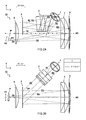
- FIG 1A shows a perspective view of an embodiment of a spectrometer 10.
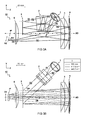
- FIGs 2 and 3 show respective side (XY) and top (YZ) view of the spectrometer 10.
- the figures include simulated optical paths of radiation R0-R5 traversing the spectrometer 10.
- FIG 1B shows an example two dimensional spectrum recorded at the image plane IP of the spectrometer 10.
- the spectrometer 10 is arranged for generating a two dimensional spectrum S.
- the spectrometer 10 comprises a main grating 3 arranged for spectrally dispersing radiation entering the spectrometer along a main dispersion direction A1.
- the spectrometer 10 comprises a cross dispersion element 2 (e.g. prism) arranged for separating diffraction orders Ox of the main grating 3.
- the orders can e.g. be separated by means of spectrally dispersing the radiation in a cross dispersion direction A2 forming an angle with the main dispersion direction A1 of the main grating 3. In this way the two dimensional spectrum S can be generated with a plurality of separated orders Ox.
- the angle between the dispersion directions A1 and A2 is preferably close to ninety degrees, i.e. transverse to one another, to have a good separation of the diffraction orders.
- the cross dispersion element 2 is preferably placed in a light path R1-R2 before the grating 3.
- the light beam R2 impinging the cross dispersion element 2 is collimated, e.g. by collimator R1..
- the spectrometer 10 comprises an imaging mirror 4 arranged for reflecting and focussing dispersed radiation R3 from the main grating 3 towards an image plane IP for imaging the two dimensional spectrum S onto the image plane IP.
- the imaging of spectrally dispersed radiation involves the converting of an angular distribution into a corresponding (in-focus) spatial distribution in the image plane IP, where a detector (not shown) can be placed to record the spectrum by its spatial distribution. While the imaging of the angularly dispersed radiation is mainly effected by the focussing mirror 4, also other optical components can play a role in determining the imaging position, focus and quality.
- the spectrometer 10 comprises a correction lens 6 arranged for correcting optical aberrations in the imaging of the two dimensional spectrum S in the image plane IP.
- the imaging mirror 4 and the correction lens 6 are both cylindrically symmetric.
- rotational shifts of these components do not affect their optical performance.
- the imaging mirror 4 and the correction lens 6 have a coinciding axis of cylindrical symmetry AS e.g. to better compensate relative shift in the system
- the correction lens 6 is arranged in an optical path between the main grating 3 and the image plane IP. In a further embodiment, the correction lens 6 is arranged in an optical path between the imaging mirror 4 and the image plane IP. Accordingly, the correction lens 6 is arranged for correcting radiation R4 reflected off the imaging mirror 4 towards the image plane IP.
- the main grating 3 is arranged partially in between the correction lens 6 and the imaging mirror 4. In other words, at least some paths between parts of the imaging mirror 4 and correction lens 6 are blocked by the main grating 3 therein between.
- the main grating 3 is arranged in the middle of the axis of cylindrical symmetry AS along the main dispersion direction A1, e.g. as shown in FIGs 2B and 3B . It may be surprising that the grating 3 is placed partially in between the optical components 4 and 6 which position may be expected to block optical paths between these components.
- the path of the radiation follows a zigzag direction along the cross dispersion direction A2 which allows the radiation R4, reflected off the imaging mirror 4, to pass the grating 3 and be projected in the image plane IP.
- a maximum angle can be provided for the diffraction along the main dispersion direction A1 in either positive or negative diffraction orders.
- the efficiency and/or acceptance angle of the spectrometer can be improved, e.g. providing an F-number of f/3.3 or better, e.g. in one embodiment the present design can provide an F-number of f/2 for a slit dimension of 25 ⁇ m.
- the main grating 3 is arranged with its surface 3s perpendicular to the axis of cylindrical symmetry AS. This perpendicular arrangement allows a symmetric distribution of positive and negative diffraction orders to be handled by the imaging mirror 4, further improving efficiency.
- the correction lens 6 is a field flattening lens arranged for flattening the image of the two dimensional spectrum S in the image plane IP.
- the field flattening lens can e.g. correct focal distances to produce a planar image of the spectrum.
- the lens may be considered part of the imaging system, e.g. providing a desired optical power to said system.
- a normal vector NV of the image plane IP is at an angle with respect to the axis of cylindrical symmetry AS. In other words, the image plane IP need not be perpendicular to the axis of cylindrical symmetry AS.
- an optical path of the radiation R3,R4 traverses a correction lens 5 once between the main grating 3 and the imaging mirror 4 and once between the imaging mirror 4 and the image plane IP.
- a correction lens twice By using a correction lens twice, its optical power can be enhanced. Embodiments without lens 5 are also possible.
- the spectrometer comprises a detector array with a two-dimensional flat arrangement of a plurality of detector elements in the imaging plane IP. It will be appreciated that a flat detector array can be relatively easy to manufacture e.g. compared to a curved detector array.
- a processor (not shown) is comprised in the instrument to control and read out other components such as the detector array and/or analyse the spectrum.
- the spectrometer 10 comprises a collimating optics 1, arranged for collimating incoming radiation R0.
- the radiation is collimated when traversing the cross dispersion element 2.
- the cross dispersion element 2 comprises a prism.
- the prism is traversed only once by an optical path of the radiation R1,R2.
- the cross dispersion element 2 is placed in a separate arm of the optical setup that guides incoming light towards the main grating 3.
- the spectrometer 10 comprises a first correction lens 6 and a second correction lens 5, wherein both correction lenses 5,6 have a coinciding axis of cylindrical symmetry AS with the imaging mirror 4.
- the first correction lens 6 is arranged (as viewed along the axis of cylindrical symmetry AS) between the grating 3 and the image plane IP while the second correction lens 5 is arranged between the main grating 3 and imaging mirror 4 (viewed along the axis AS).
- the correction lenses may contribute to correcting, e.g. flattening, the image as well as displacing a position of the image plane IP.
- a single correction lens can be used.
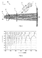
- FIG 4 shows a top view of a second embodiment wherein a single correction lens 6' is used.
- the correction lens 6' has a coinciding axis of cylindrical symmetry AS with the imaging mirror 4.
- the main grating 3 is arranged to have radiation R2 impinge the main grating 3 with an angle of incidence ⁇ 2 below 30 degrees in the cross dispersion direction A2, e.g. as illustrated in FIGs 2A and 3A , preferably even lower, e.g. between 10 and 20 degrees.
- the angle of incidence ⁇ 2 can determine a zigzag angle of the radiation path R2, R3,R4 which angle is preferably as low as possible for having close to normal incidence on the imaging mirror 4 without the back reflected radiation R4 clipping on the main grating 3.
- the main grating 3 is arranged to have radiation R2 impinge the main grating 3 with an angle of incidence ⁇ 1 below 50 degrees in the main dispersion direction A1, e.g. as illustrated in FIGs 2B and 3B , preferably even lower, e.g. between 10 and 40 degrees.
- the lower angle of incidence ⁇ 1 in the main dispersion direction A1 may correspond to lower diffraction orders being used.
- the main grating 3 has a line density of at least 150 lines per millimetre, preferably at least 300 lines per millimetre.
- the main grating 3 is adapted for projecting diffraction orders Ox below order fifteen onto the image plane IP.
- FIG 5 shows a graph of a typical grating efficiency n as a function of wavelength ⁇ for different diffraction orders 06 (order 6) ... O18 (order 18).
- n typically cover a larger wavelength range than higher diffraction orders and may provide a more sensitive system. Accordingly, it is found advantageous to use the lower diffraction orders, to simplify reconstruction of the spectral features from the two dimensional spectral image.
- One aspect of the present disclosure provides a method for generating a two dimensional spectrum S.
- the method comprises using a main grating 3 for spectrally dispersing radiation along a main dispersion direction A1.
- the method further comprises using a cross dispersion element 2 for separating diffraction orders Ox of the main grating 3 by means of spectrally dispersing the radiation in a cross dispersion direction A2 forming an angle with the main dispersion direction A1 of the main grating 3 adapted to generate the two dimensional spectrum S with a plurality of separated orders Ox.
- the method further comprises using an imaging mirror 4 for reflecting and focussing dispersed radiation R3 from the main grating 3 towards an image plane IP for imaging the two dimensional spectrum S onto the image plane IP.
- the method further comprises using a correction lens 6 for correcting optical aberrations in the imaging of the two dimensional spectrum S in the image plane IP.
- the imaging mirror 4 and the correction lens 6 have a coinciding axis of cylindrical symmetry
- the method comprises measuring a first two dimensional spectrum S using a first main grating; replacing the first main grating with a second main grating while keeping the imaging mirror 4, correction lens 6, and image plane IP unchanged; and measuring a second two dimensional spectrum using the second main grating.
- the presently disclosed spectrometer is particularly suitable to allow easy replacement of the grating, e.g. if measuring at another wavelength range is desired using a second main grating having a different line density than the first main grating.
- all components are kept at the same position and a change in bandwidth and resolution is effected by only replacing the grating. This can provide advantages in terms of manufacturability and use.
- radiation R0 from an origin is collimated and reflected by mirror 1 as radiation R1 impinging the prism 2.
- the radiation R2 While traversing the prism 2, the radiation R2 is given a small wavelength dependent angular distribution in the cross dispersion direction A2.
- Said radiation R2 impinges the grating 3 under an angle of incidence ⁇ 1, ⁇ 2 and is refracted in a wavelength dependent direction as radiation R3 towards the focusing mirror 4.
- the radiation R3 passes through a lens 5 before and after impinging the mirror 4.
- the reflected radiation R4 is focussed by the combined optics 4 and 5 as well as additional lens 6 in the imaging plane IP.
- the embodiment of FIG 4 is similar though without the second lens 5.
Abstract
The present disclosure concerns a spectrometer (10) and method for generating a two dimensional spectrum (S). The spectrometer (10) comprises a main grating (3) and cross dispersion element (2). An imaging mirror (4) is arranged for reflecting and focussing dispersed radiation (R3) from the main grating (3) towards an image plane (IP) for imaging the two dimensional spectrum (S) onto an image plane (IP) of the spectrometer (10). A correction lens (6) is arranged for correcting optical aberrations in the imaging of the two dimensional spectrum (S) in the image plane (IP). The imaging mirror (4) and correction lens (6) have a coinciding axis of cylindrical symmetry (AS).
Description
- The present disclosure relates to a spectrometer for generating a two dimensional spectrum.
- A spectrometer is an instrument used to probe a property of light as a function of its portion of the electromagnetic spectrum, e.g. for spectrally resolving the light. The term 'light' or 'radiation' as used herein includes all forms of electromagnetic radiation such as visible, infrared and/or ultraviolet radiation. Typically, a spectrometer comprises reflective and/or refractive optics for guiding and shaping the light as well as a dispersion element such as a grating and/or prism for refracting, diffracting and/or dispersing the light in a wavelength dependent angle. Depending on the angle, different spectral components of the light can be imaged at different locations along a spectral axis in an imaging plane of the spectrometer. A sensor can be arranged for detecting spectral components of the light in the imaging plane.
- In a typical spectrometer, light is dispersed along a single spectral axis. A disadvantage of such a spectrometer can be that for measuring a large bandwidth of light with a high resolution, a long (one dimensional) detector is needed to capture the spectral image. This can be alleviated by providing a spectrometer that generates a two dimensional spectrum, i.e. projects a two dimensional image wherein light is dispersed along two spectral axes. In this way the spectral image and corresponding detector can be more compact for a relatively high bandwidth and resolution.
-
EP1754032 B1 described a spectrometer assembly with a spectrometer for generating a radiation spectrum in a first wavelength range of a light source on a detector. The spectrometer comprises an Echelle grating for spectrally dispersing radiation entering the spectrometer assembly in a main dispersion direction. The spectrometer further comprises a dispersion element for separating the orders by means of spectrally dispersing the radiation in a lateral dispersion direction forming an angle with the main dispersion direction of the Echelle grating. The grating and dispersion element are adapted to generate a two dimensional spectrum with a plurality of separated orders. The spectrometer further comprises an imaging optical system for imaging the radiation entering through an entrance slit into the spectrometer assembly in an imaging plane. The spectrometer further comprises a detector array with a two-dimensional arrangement of a plurality of detector elements in the imaging plane. - There is yet a desire for an improved spectrometer for generating a two dimensional spectrum, in particular with regards to stability and manufacturability.
- A first aspect of the present disclosure provides a spectrometer for generating a two dimensional spectrum, the spectrometer comprising a main grating arranged for spectrally dispersing radiation entering the spectrometer along a main dispersion direction; a cross dispersion element arranged for separating diffraction orders of the main grating by means of spectrally dispersing the radiation in a cross dispersion direction forming an angle with the main dispersion direction of the main grating adapted to generate the two dimensional spectrum with a plurality of separated orders; an imaging mirror arranged for reflecting and focussing dispersed radiation from the main grating towards an image plane for imaging the two dimensional spectrum onto the image plane; and a correction lens arranged for correcting optical aberrations in the imaging of the two dimensional spectrum in the image plane; wherein the imaging mirror and the correction lens have a coinciding axis of cylindrical symmetry.
- By using a cross dispersion element for separating diffraction orders, the spectrum can be imaged in a more compact way. By using an imaging mirror for reflecting and focussing dispersed radiation from the main grating towards an image plane, the spectrometer design can be relatively compact. However, the combined dispersion/refraction caused by the main grating and cross dispersion element may result in an angular distribution of radiation impinging the imaging mirror which can lead to optical aberrations in the image plane. By introducing a correction lens, such aberrations can be at least partially counteracted. However, it is found that the ability of the correction lens is sensitive to its exact placement with respect to the other optical elements, in particular the imaging mirror. It is found that inexact positioning of the correction lens during manufacturing can lead to deteriorated properties of the spectrometer. Furthermore, in use, optical components can become relatively shifted e.g. due to thermal or other stress, which can also deteriorate performance.
- The inventors find that the conventional spectrometer design for generating two dimensional spectra can be improved by introducing symmetries between specific optical elements that are conventionally not considered. In particular, it is found that by placing the imaging mirror and correction lens such that their axis of cylindrical symmetry coincides, relative placement accuracy of these elements can be improved both during manufacturing and active use of the spectrometer. As will be appreciated, the symmetric arrangement can allow for greater tolerances to e.g. (thermal) shifting and expansion of components. Specifically, due to the symmetric arrangement, the shift and expansion of optical components can occur symmetrically and partly cancel each other out. Furthermore, the imaging mirror and correction lens can be more easily centred with respect to each other e.g. by mechanical means, for example a common cylindrical housing. Alternatively or in addition, the components can be placed from one side against a common contact surface. Especially if the components have the same size, they can be positioned with a flush contact surface from one side. In this way, there can also be a simple yet accurate enclosure of the optical components. Accordingly, by these and other aspects of the present disclosure an improved spectrometer for generating a two dimensional spectrum, in particular with regards to manufacturability and stability, can be provided.
- By using a field flattening lens as the correction lens, the image of the two dimensional spectrum in the image plane can be flattened. In this way a flat detector array can be used to capture the spectral image. For example, a detector array with a two-dimensional flat arrangement of a plurality of detector elements can be placed in the imaging plane to register the spectral image. Such a typical flat detector array can be especially useful when the image has been flattened. Depending on the correction lens, it can be advantageous to project an image having a normal vector that is at an angle with respect to the axis of cylindrical symmetry, i.e. the image plane is tilted. Alternatively or in addition to the field flattening lens also other correction lenses can be used, e.g. for correcting other types of aberration and/or for combining their corrective effects. Preferably, when using two or more correction lenses, each has a coinciding axis of cylindrical symmetry with the imaging mirror, e.g. for similar reasons as noted above. By having an optical path of the radiation traverse a correction twice, its corrective function can be enhanced. For example, a correction lens can be placed between the main grating and the imaging mirror to be traversed twice.
- By arranging the main grating partially in between the correction lens and the imaging mirror, an angle of incidence of the dispersed radiation onto the cylindrically symmetric imaging mirror can be lowered. By lowering the angle of incidence, optical aberrations of the imaging can be lowered. The more the grating can be positioned in between the correction lens and the imaging mirror, the lower the angle of incidence, and the lower the optical aberrations, particularly for a spherical mirror. On the other hand, the grating can block part of the light between the imaging mirror and correction lens. As a compromise, the main grating can be inserted about half way in between the imaging mirror and correction lens. For similar reasons, by having the main grating arranged to have radiation impinge the main grating with a relatively low angle of incidence in the cross dispersion direction, aberrations can be lowered. For example, an angle of incidence is preferably below 40 degrees, more preferably below 30 degrees, even more preferable below 20 degrees, e.g. between 5 and 30 degrees.
- By arranging the main grating in the middle of the axis of cylindrical symmetry along the main dispersion direction, a relatively wide range of diffraction angles can be imaged by the imaging mirror. This may contribute to an improved efficiency of the spectrometer. For example, when light enters the spectrometer beyond a certain acceptance angle and some wavelengths of that light are refracted outside the area of the imaging mirror, efficiency of the spectrometer can be lower. By arranging the main grating with its surface perpendicular to the axis of cylindrical symmetry, the spectrometer can be relatively insensitive to rotation of the grating. Furthermore, placement accuracy of the grating during manufacturing can be improved. Furthermore, relative ease of placement combined with the symmetrical design can contribute to the option of easily replacing the grating, e.g. if it is desired to use the spectrometer for a different wavelength range and/or resolution by using another grating having a different line density and/or groove profile.
- Preferably, the main grating is adapted for projecting relatively low diffraction orders onto the image plane. By using lower diffraction orders, a larger part of the spectrum may be covered per order. For example, preferably, diffraction orders fifteen and below are used. The diffraction orders may depend e.g. on the line density of the grating and/or the geometry of the incident radiation. Preferably, the main grating has a line density of at least 150 lines per millimetre, preferably at least 300 lines per millimetre. Alternatively or in addition, relatively low incidence angles are used as detailed above.
- Using a prism as the cross dispersion element provides a relatively efficient and simple way of cross-dispersing the radiation and separating otherwise overlapping orders of the diffraction grating. By having the radiation traverse the prism only once losses at the interfaces can be minimized. Furthermore, it allows the prism to be placed outside the path between the grating and imaging mirror thus maintaining the symmetry of the system. Alternative to the prism, also other cross dispersion elements can be used, e.g. a cross dispersion grating.
- A second aspect of the present disclosure provides a method for generating a two dimensional spectrum, the method comprising using a main grating for spectrally dispersing radiation along a main dispersion direction; using a cross dispersion element for separating diffraction orders of the main grating by means of spectrally dispersing the radiation in a cross dispersion direction forming an angle with the main dispersion direction of the main grating adapted to generate the two dimensional spectrum with a plurality of separated orders; using an imaging mirror for reflecting and focussing dispersed radiation from the main grating towards an image plane for imaging the two dimensional spectrum onto the image plane; and using a correction lens for correcting optical aberrations in the imaging of the two dimensional spectrum in the image plane; wherein the imaging mirror and the correction lens have a coinciding axis of cylindrical symmetry. The method can provide similar advantages as the spectrometer.
- These and other features, aspects, and advantages of the apparatus, systems and methods of the present disclosure will become better understood from the following description, appended claims, and accompanying drawing wherein:
-
FIG 1A shows a perspective view of an embodiment of a spectrometer according to the first aspect; -
FIG 1B shows a two dimensional spectrum recorded at the image plane of the spectrometer; -
FIG 2A and 2B show a respective side and top view of the spectrometer wherein the optical paths of one wavelength and one grating order is shown; -
FIG 3A and 3B show a respective side and top view of the spectrometer wherein the optical paths of three wavelengths and one grating order is shown; -
FIG 4 shows a top view of an alternative embodiment of the spectrometer wherein the optical paths of multiple wavelengths and grating orders is shown; -
FIG 5 shows a graph of grating efficiency as a function of wavelength for different diffraction orders. - Unless otherwise defined, all terms (including technical and scientific terms) used herein have the same meaning as commonly understood by one of ordinary skill in the art to which this invention belongs as read in the context of the description and drawings. It will be further understood that terms, such as those defined in commonly used dictionaries, should be interpreted as having a meaning that is consistent with their meaning in the context of the relevant art and will not be interpreted in an idealized or overly formal sense unless expressly so defined herein. In some instances, detailed descriptions of well-known devices and methods may be omitted so as not to obscure the description of the present systems and methods. Terminology used for describing particular embodiments is not intended to be limiting of the invention. As used herein, the singular forms "a", "an" and "the" are intended to include the plural forms as well, unless the context clearly indicates otherwise. The term "and/or" includes any and all combinations of one or more of the associated listed items. It will be understood that the terms "comprises" and/or "comprising" specify the presence of stated features but do not preclude the presence or addition of one or more other features. It will be further understood that when a particular step of a method is referred to as subsequent to another step, it can directly follow said other step or one or more intermediate steps may be carried out before carrying out the particular step, unless specified otherwise. Likewise it will be understood that when a connection between structures or components is described, this connection may be established directly or through intermediate structures or components unless specified otherwise. All publications, patent applications, patents, and other references mentioned herein are incorporated by reference in their entirety. In case of conflict, the present specification, including definitions, will control.
- When an object has cylindrical symmetry, this means the object can be rotated around an axis by any angle without affecting its appearance. The axis around which the object is cylindrically symmetric is referred to as the axis of cylindrical symmetry. When a lens or mirror is cylindrically symmetric this means it can be arbitrarily rotated around its axis of cylindrical symmetry without affecting its optical function or performance.
- An optical aberration is a departure of the performance of an optical system from the predictions of paraxial optics. For example monochromatic aberrations can be caused by the geometry of the lens/mirror and can occur both when light is reflected and when it is refracted. Chromatic aberrations can be caused by the variation of a lens's refractive index with wavelength. Some aberration can be corrected by introducing further optical element, e.g. 'correction lenses' that at least partially counteract the effect of the aberration.
- For example, Petzval field curvature describes the optical aberration in which a flat object normal to the optical axis cannot be brought into focus on a flat image plane. A field flattening lens counteracts the Petzval field curvature of an optical system by shifting the focal points of the Petzval surface to lie in the same plane thereby countering the field-angle dependence of the focal length of the system. By flattening the image, a typical flat sensor array can be used in the image plane to correctly register said image.
- The invention is described more fully hereinafter with reference to the accompanying drawings, in which embodiments of the invention are shown. This invention may, however, be embodied in many different forms and should not be construed as limited to the embodiments set forth herein. Rather, these embodiments are provided so that this disclosure will be thorough and complete, and will fully convey the scope of the invention to those skilled in the art. The description of the exemplary embodiments is intended to be read in connection with the accompanying drawings, which are to be considered part of the entire written description. In the drawings, the absolute and relative sizes of systems, components, layers, and regions may be exaggerated for clarity. Embodiments may be described with reference to schematic and/or cross-section illustrations of possibly idealized embodiments and intermediate structures of the invention. In the description and drawings, like numbers refer to like elements throughout. Relative terms as well as derivatives thereof should be construed to refer to the orientation as then described or as shown in the drawing under discussion. These relative terms are for convenience of description and do not require that the system be constructed or operated in a particular orientation unless stated otherwise.
-
FIG 1A shows a perspective view of an embodiment of aspectrometer 10.FIGs 2 and3 show respective side (XY) and top (YZ) view of thespectrometer 10. The figures include simulated optical paths of radiation R0-R5 traversing thespectrometer 10. For illustration purposes,FIG 2A and 2B show the optical paths of one wavelength (λ = 417.5nm) and one grating order (grating order 11).FIG 3A and 3B show the optical paths of three wavelengths (λ = 395nm, 417.5nm, 440.5nm) and one grating order (grating order 11).FIG 1B shows an example two dimensional spectrum recorded at the image plane IP of thespectrometer 10. - The
spectrometer 10 is arranged for generating a two dimensional spectrum S. Thespectrometer 10 comprises amain grating 3 arranged for spectrally dispersing radiation entering the spectrometer along a main dispersion direction A1. Thespectrometer 10 comprises a cross dispersion element 2 (e.g. prism) arranged for separating diffraction orders Ox of themain grating 3. The orders can e.g. be separated by means of spectrally dispersing the radiation in a cross dispersion direction A2 forming an angle with the main dispersion direction A1 of themain grating 3. In this way the two dimensional spectrum S can be generated with a plurality of separated orders Ox. Although other angles are possible, the angle between the dispersion directions A1 and A2 is preferably close to ninety degrees, i.e. transverse to one another, to have a good separation of the diffraction orders. Thecross dispersion element 2 is preferably placed in a light path R1-R2 before thegrating 3. Preferably, the light beam R2 impinging thecross dispersion element 2 is collimated, e.g. by collimator R1.. - The
spectrometer 10 comprises animaging mirror 4 arranged for reflecting and focussing dispersed radiation R3 from themain grating 3 towards an image plane IP for imaging the two dimensional spectrum S onto the image plane IP. The imaging of spectrally dispersed radiation involves the converting of an angular distribution into a corresponding (in-focus) spatial distribution in the image plane IP, where a detector (not shown) can be placed to record the spectrum by its spatial distribution. While the imaging of the angularly dispersed radiation is mainly effected by the focussingmirror 4, also other optical components can play a role in determining the imaging position, focus and quality. In particular, thespectrometer 10 comprises acorrection lens 6 arranged for correcting optical aberrations in the imaging of the two dimensional spectrum S in the image plane IP. Preferably, theimaging mirror 4 and thecorrection lens 6 are both cylindrically symmetric. By using an imaging mirror and correction lens that are cylindrically symmetric, rotational shifts of these components do not affect their optical performance. Furthermore, preferably, theimaging mirror 4 and thecorrection lens 6 have a coinciding axis of cylindrical symmetry AS e.g. to better compensate relative shift in the system - In one embodiment, the
correction lens 6 is arranged in an optical path between themain grating 3 and the image plane IP. In a further embodiment, thecorrection lens 6 is arranged in an optical path between theimaging mirror 4 and the image plane IP. Accordingly, thecorrection lens 6 is arranged for correcting radiation R4 reflected off theimaging mirror 4 towards the image plane IP. - As particularly illustrated by
FIGs 2A and3A , in one embodiment, themain grating 3 is arranged partially in between thecorrection lens 6 and theimaging mirror 4. In other words, at least some paths between parts of theimaging mirror 4 andcorrection lens 6 are blocked by themain grating 3 therein between. Alternatively or in addition, in one embodiment, themain grating 3 is arranged in the middle of the axis of cylindrical symmetry AS along the main dispersion direction A1, e.g. as shown inFIGs 2B and3B . It may be surprising that thegrating 3 is placed partially in between theoptical components imaging mirror 4, to pass thegrating 3 and be projected in the image plane IP. At the same time by placing the grating in the middle, a maximum angle can be provided for the diffraction along the main dispersion direction A1 in either positive or negative diffraction orders. In this way, the efficiency and/or acceptance angle of the spectrometer can be improved, e.g. providing an F-number of f/3.3 or better, e.g. in one embodiment the present design can provide an F-number of f/2 for a slit dimension of 25 µm. - In one embodiment, the
main grating 3 is arranged with itssurface 3s perpendicular to the axis of cylindrical symmetry AS. This perpendicular arrangement allows a symmetric distribution of positive and negative diffraction orders to be handled by theimaging mirror 4, further improving efficiency. - In one embodiment, the
correction lens 6 is a field flattening lens arranged for flattening the image of the two dimensional spectrum S in the image plane IP. The field flattening lens can e.g. correct focal distances to produce a planar image of the spectrum. The lens may be considered part of the imaging system, e.g. providing a desired optical power to said system. In one embodiment, a normal vector NV of the image plane IP is at an angle with respect to the axis of cylindrical symmetry AS. In other words, the image plane IP need not be perpendicular to the axis of cylindrical symmetry AS. - In one embodiment, an optical path of the radiation R3,R4 traverses a
correction lens 5 once between themain grating 3 and theimaging mirror 4 and once between theimaging mirror 4 and the image plane IP. By using a correction lens twice, its optical power can be enhanced. Embodiments withoutlens 5 are also possible. - In one embodiment (not shown), the spectrometer comprises a detector array with a two-dimensional flat arrangement of a plurality of detector elements in the imaging plane IP. It will be appreciated that a flat detector array can be relatively easy to manufacture e.g. compared to a curved detector array. In one embodiment a processor (not shown) is comprised in the instrument to control and read out other components such as the detector array and/or analyse the spectrum.
- In one embodiment, the
spectrometer 10 comprises acollimating optics 1, arranged for collimating incoming radiation R0. Preferably, the radiation is collimated when traversing thecross dispersion element 2. In one embodiment, thecross dispersion element 2 comprises a prism. In a further embodiment the prism is traversed only once by an optical path of the radiation R1,R2. In one embodiment, thecross dispersion element 2 is placed in a separate arm of the optical setup that guides incoming light towards themain grating 3. - In one embodiment, the
spectrometer 10 comprises afirst correction lens 6 and asecond correction lens 5, wherein bothcorrection lenses imaging mirror 4. In one embodiment, thefirst correction lens 6 is arranged (as viewed along the axis of cylindrical symmetry AS) between thegrating 3 and the image plane IP while thesecond correction lens 5 is arranged between themain grating 3 and imaging mirror 4 (viewed along the axis AS). The correction lenses may contribute to correcting, e.g. flattening, the image as well as displacing a position of the image plane IP. Alternative to using multiple correction lenses, also a single correction lens can be used. For example,FIG 4 shows a top view of a second embodiment wherein a single correction lens 6' is used. As with the first embodiment, the correction lens 6' has a coinciding axis of cylindrical symmetry AS with theimaging mirror 4. - In one embodiment, the
main grating 3 is arranged to have radiation R2 impinge themain grating 3 with an angle of incidence θ2 below 30 degrees in the cross dispersion direction A2, e.g. as illustrated inFIGs 2A and3A , preferably even lower, e.g. between 10 and 20 degrees. It will be noted that the angle of incidence θ2 can determine a zigzag angle of the radiation path R2, R3,R4 which angle is preferably as low as possible for having close to normal incidence on theimaging mirror 4 without the back reflected radiation R4 clipping on themain grating 3. In one embodiment, themain grating 3 is arranged to have radiation R2 impinge themain grating 3 with an angle of incidence θ1 below 50 degrees in the main dispersion direction A1, e.g. as illustrated inFIGs 2B and3B , preferably even lower, e.g. between 10 and 40 degrees. Typically, the lower angle of incidence θ1 in the main dispersion direction A1 may correspond to lower diffraction orders being used. In one embodiment, themain grating 3 has a line density of at least 150 lines per millimetre, preferably at least 300 lines per millimetre. In one embodiment, themain grating 3 is adapted for projecting diffraction orders Ox below order fifteen onto the image plane IP. - The present embodiments may be contrasted to conventional 'Echelle' grating based spectrometers which typically feature higher line densities, higher angles of incidence, and/or are used for higher and more diffraction orders.
FIG 5 shows a graph of a typical grating efficiency n as a function of wavelength λ for different diffraction orders 06 (order 6) ... O18 (order 18). It can be noted that lower diffraction orders typically cover a larger wavelength range than higher diffraction orders and may provide a more sensitive system. Accordingly, it is found advantageous to use the lower diffraction orders, to simplify reconstruction of the spectral features from the two dimensional spectral image. - One aspect of the present disclosure provides a method for generating a two dimensional spectrum S. The method comprises using a
main grating 3 for spectrally dispersing radiation along a main dispersion direction A1. The method further comprises using across dispersion element 2 for separating diffraction orders Ox of themain grating 3 by means of spectrally dispersing the radiation in a cross dispersion direction A2 forming an angle with the main dispersion direction A1 of themain grating 3 adapted to generate the two dimensional spectrum S with a plurality of separated orders Ox. The method further comprises using animaging mirror 4 for reflecting and focussing dispersed radiation R3 from themain grating 3 towards an image plane IP for imaging the two dimensional spectrum S onto the image plane IP. The method further comprises using acorrection lens 6 for correcting optical aberrations in the imaging of the two dimensional spectrum S in the image plane IP. In the method, theimaging mirror 4 and thecorrection lens 6 have a coinciding axis of cylindrical symmetry AS. - In one embodiment, the method comprises measuring a first two dimensional spectrum S using a first main grating; replacing the first main grating with a second main grating while keeping the
imaging mirror 4,correction lens 6, and image plane IP unchanged; and measuring a second two dimensional spectrum using the second main grating. It will be appreciated that the presently disclosed spectrometer is particularly suitable to allow easy replacement of the grating, e.g. if measuring at another wavelength range is desired using a second main grating having a different line density than the first main grating. Advantageously, in one embodiment all components are kept at the same position and a change in bandwidth and resolution is effected by only replacing the grating. This can provide advantages in terms of manufacturability and use. - With specific reference to the embodiment of
FIGs 1A ,2 , and3 , radiation R0 from an origin (e.g. slit or spot) is collimated and reflected bymirror 1 as radiation R1 impinging theprism 2. While traversing theprism 2, the radiation R2 is given a small wavelength dependent angular distribution in the cross dispersion direction A2. Said radiation R2 impinges thegrating 3 under an angle of incidence θ1,θ2 and is refracted in a wavelength dependent direction as radiation R3 towards the focusingmirror 4. The radiation R3 passes through alens 5 before and after impinging themirror 4. The reflected radiation R4 is focussed by the combinedoptics additional lens 6 in the imaging plane IP. The embodiment ofFIG 4 is similar though without thesecond lens 5. - While example embodiments were shown for spectrometer arrangements, also alternative ways may be envisaged by those skilled in the art having the benefit of the present disclosure for achieving a similar function and result. E.g. optical components may be combined or split up into one or more alternative or equivalent components. The various elements of the embodiments as discussed and shown offer certain advantages, such as improved stability and manufacturability. Of course, it is to be appreciated that any one of the above embodiments or processes may be combined with one or more other embodiments or processes to provide even further improvements in finding and matching designs and advantages. It is appreciated that this disclosure offers particular advantages to spectrometers for generating a two dimensional spectrum, and in general could be applied for other spectrometers designs.
- While the present systems and methods have been described in particular detail with reference to specific exemplary embodiments thereof, it should also be appreciated that numerous modifications and alternative embodiments may be devised by those having ordinary skill in the art without departing from the scope of the present disclosure. For example, embodiments wherein devices or systems are disclosed to be arranged and/or constructed for performing a specified method or function inherently disclose the method or function as such and/or in combination with other disclosed embodiments of methods or systems. Furthermore, embodiments of methods are considered to inherently disclose their implementation in respective hardware, where possible, in combination with other disclosed embodiments of methods or systems. Furthermore, methods that can be embodied as program instructions, e.g. on a non-transient computer-readable storage medium, are considered inherently disclosed as such embodiment.
- Finally, the above-discussion is intended to be merely illustrative of the present systems and/or methods and should not be construed as limiting the appended claims to any particular embodiment or group of embodiments. The specification and drawings are accordingly to be regarded in an illustrative manner and are not intended to limit the scope of the appended claims. In interpreting the appended claims, it should be understood that the word "comprising" does not exclude the presence of other elements or acts than those listed in a given claim; the word "a" or "an" preceding an element does not exclude the presence of a plurality of such elements; any reference signs in the claims do not limit their scope; several "means" may be represented by the same or different item(s) or implemented structure or function; any of the disclosed devices or portions thereof may be combined together or separated into further portions unless specifically stated otherwise. The mere fact that certain measures are recited in mutually different claims does not indicate that a combination of these measures cannot be used to advantage. In particular, all working combinations of the claims are considered inherently disclosed.
Claims (15)
- Spectrometer (10) for generating a two dimensional spectrum (S), the spectrometer (10) comprising- a main grating (3) arranged for spectrally dispersing radiation entering the spectrometer along a main dispersion direction (A1);- a cross dispersion element (2) arranged for separating diffraction orders (Ox) of the main grating (3) by means of spectrally dispersing the radiation in a cross dispersion direction (A2) forming an angle with the main dispersion direction (A1) of the main grating (3) adapted to generate the two dimensional spectrum (S) with a plurality of separated orders (Ox);- an imaging mirror (4) arranged for reflecting and focussing dispersed radiation (R3) from the main grating (3) towards an image plane (IP) for imaging the two dimensional spectrum (S) onto the image plane (IP); and- a correction lens (6) arranged for correcting optical aberrations in the imaging of the two dimensional spectrum (S) in the image plane (IP); wherein- the imaging mirror (4) and the correction lens (6) have a coinciding axis of cylindrical symmetry (AS).
- Spectrometer according to any of the preceding claims, wherein the main grating (3) is arranged partially in between the correction lens (6) and the imaging mirror (4).
- Spectrometer according to any of the preceding claims, wherein the main grating (3) is arranged in the middle of the axis of cylindrical symmetry (AS) along the main dispersion direction (A1).
- Spectrometer according to any of the preceding claims, wherein the main grating (3) is arranged with its surface (3s) perpendicular to the axis of cylindrical symmetry (AS).
- Spectrometer according to any of the preceding claims, wherein the correction lens (6) is a field flattening lens arranged for flattening the image of the two dimensional spectrum (S) in the image plane (IP).
- Spectrometer according to any of the preceding claims, wherein a normal vector (NV) of the image plane (IP) is at an angle with respect to the axis of cylindrical symmetry (AS).
- Spectrometer according to any of the preceding claims, wherein the spectrometer (10) comprises a first correction lens (6) and a second correction lens (5), wherein both correction lenses (5,6) have a coinciding axis of cylindrical symmetry (AS) with the imaging mirror (4).
- Spectrometer according to any of the preceding claims, wherein an optical path of the radiation (R3,R4) traverses a second correction lens (5) once between the main grating (3) and the imaging mirror (4) and once between the imaging mirror (4) and the image plane (IP)
- Spectrometer according to any of the preceding claims, further comprising a detector array with a two-dimensional flat arrangement of a plurality of detector elements in the imaging plane (5).
- Spectrometer according to any of the preceding claims, wherein the cross dispersion element (2) comprises a prism that is traversed only once by an optical path of the radiation (R1,R2).
- Spectrometer according to any of the preceding claims, wherein the main grating (3) is arranged to have radiation (R2) impinge the main grating (3) with an angle of incidence below 30 degrees in the cross dispersion direction (A2).
- Spectrometer according to any of the preceding claims, wherein the main grating (3) has a line density of at least 150 lines per millimetre, preferably at least 300 lines per millimetre.
- Spectrometer according to any of the preceding claims, wherein the main grating (3) is adapted for projecting diffraction orders (Ox) below order fifteen onto the image plane (IP).
- Method for generating a two dimensional spectrum (S), the method comprising- using a main grating (3) for spectrally dispersing radiation along a main dispersion direction (A1);- using a cross dispersion element (2) for separating diffraction orders (Ox) of the main grating (3) by means of spectrally dispersing the radiation in a cross dispersion direction (A2) forming an angle with the main dispersion direction (A1) of the main grating (3) adapted to generate the two dimensional spectrum (S) with a plurality of separated orders (Ox);- using an imaging mirror (4) for reflecting and focussing dispersed radiation (R3) from the main grating (3) towards an image plane (IP) for imaging the two dimensional spectrum (S) onto the image plane (IP); and- using a correction lens (6) for correcting optical aberrations in the imaging of the two dimensional spectrum (S) in the image plane (IP); wherein- the imaging mirror (4) and the correction lens (6) have a coinciding axis of cylindrical symmetry (AS).
- Method according to claim 14, comprising- measuring a first two dimensional spectrum (S) using a first main grating;- replacing the first main grating with a second main grating having a different line density in order to change the instrument bandwidth and/or resolution while keeping the imaging mirror (4), correction lens (6), and image plane (IP) unchanged; and- measuring a second two dimensional spectrum using the second main grating.
Priority Applications (4)
| Application Number | Priority Date | Filing Date | Title |
|---|---|---|---|
| EP13197479.2A EP2884247A1 (en) | 2013-12-16 | 2013-12-16 | Spectrometer for generating a two dimensional spectrum |
| US15/104,755 US10288481B2 (en) | 2013-12-16 | 2014-12-16 | Spectrometer for generating a two dimensional spectrum |
| PCT/NL2014/050865 WO2015093944A1 (en) | 2013-12-16 | 2014-12-16 | Spectrometer for generating a two dimensional spectrum |
| EP14825460.0A EP3084373B1 (en) | 2013-12-16 | 2014-12-16 | Spectrometer for generating a two dimensional spectrum |
Applications Claiming Priority (1)
| Application Number | Priority Date | Filing Date | Title |
|---|---|---|---|
| EP13197479.2A EP2884247A1 (en) | 2013-12-16 | 2013-12-16 | Spectrometer for generating a two dimensional spectrum |
Publications (1)
| Publication Number | Publication Date |
|---|---|
| EP2884247A1 true EP2884247A1 (en) | 2015-06-17 |
Family
ID=49759218
Family Applications (2)
| Application Number | Title | Priority Date | Filing Date |
|---|---|---|---|
| EP13197479.2A Withdrawn EP2884247A1 (en) | 2013-12-16 | 2013-12-16 | Spectrometer for generating a two dimensional spectrum |
| EP14825460.0A Active EP3084373B1 (en) | 2013-12-16 | 2014-12-16 | Spectrometer for generating a two dimensional spectrum |
Family Applications After (1)
| Application Number | Title | Priority Date | Filing Date |
|---|---|---|---|
| EP14825460.0A Active EP3084373B1 (en) | 2013-12-16 | 2014-12-16 | Spectrometer for generating a two dimensional spectrum |
Country Status (3)
| Country | Link |
|---|---|
| US (1) | US10288481B2 (en) |
| EP (2) | EP2884247A1 (en) |
| WO (1) | WO2015093944A1 (en) |
Cited By (3)
| Publication number | Priority date | Publication date | Assignee | Title |
|---|---|---|---|---|
| WO2018138609A1 (en) * | 2017-01-25 | 2018-08-02 | Rathore Shubham | Spectrometer and method for measuring the spectral characteristics thereof |
| CN110553733A (en) * | 2018-06-04 | 2019-12-10 | 耶拿分析仪器股份公司 | Spectrometer apparatus |
| WO2020081319A1 (en) * | 2018-10-17 | 2020-04-23 | Rigaku Analytical Devices, Inc. | Compact two-dimensional spectrometer |
Families Citing this family (6)
| Publication number | Priority date | Publication date | Assignee | Title |
|---|---|---|---|---|
| JP2019527576A (en) | 2016-07-15 | 2019-10-03 | キヤノン ユーエスエイ, インコーポレイテッドCanon U.S.A., Inc | Spectral encoding probe |
| EP3401656A1 (en) * | 2017-05-11 | 2018-11-14 | Nederlandse Organisatie voor toegepast- natuurwetenschappelijk onderzoek TNO | Correction of curved projection of a spectrometer slit line |
| EP3580537B1 (en) | 2017-02-08 | 2021-08-11 | Nederlandse Organisatie voor toegepast- natuurwetenschappelijk onderzoek TNO | Correction of curved projection of a spectrometer slit line |
| DE102019113478A1 (en) * | 2019-05-21 | 2020-11-26 | Analytik Jena Ag | Spectrometer arrangement |
| CN112539836B (en) * | 2020-11-20 | 2022-03-25 | 中国科学院西安光学精密机械研究所 | Spectrum imaging system based on forearm compensation and planar grating |
| CN115790850A (en) * | 2023-02-09 | 2023-03-14 | 浙江大学 | High dynamic range high resolution split frame snapshot type hyperspectral imaging system |
Citations (11)
| Publication number | Priority date | Publication date | Assignee | Title |
|---|---|---|---|---|
| US3658423A (en) * | 1971-01-14 | 1972-04-25 | Spectrametrics Inc | Echelle spectrometer |
| US3922089A (en) * | 1972-03-17 | 1975-11-25 | Nils Allan Danielsson | Apparatus and method for the uniform separation of spectral orders |
| US4995721A (en) * | 1990-03-05 | 1991-02-26 | Imo Industries, Inc. | Two-dimensional spectrometer |
| US5018856A (en) * | 1989-10-30 | 1991-05-28 | The United States Of America As Represented By The Secretary Of Agriculture | Continuum source atomic absorption spectrometry |
| US5565983A (en) * | 1995-05-26 | 1996-10-15 | The Perkin-Elmer Corporation | Optical spectrometer for detecting spectra in separate ranges |
| US20060038997A1 (en) * | 2004-08-19 | 2006-02-23 | Julian Jason P | Multi-channel, multi-spectrum imaging spectrometer |
| EP1806606A1 (en) * | 2006-01-05 | 2007-07-11 | Fujitsu Ltd. | Wavelength selection device |
| EP1754032B1 (en) | 2004-06-09 | 2008-05-07 | Gesellschaft zur Förderung angewandter Optik, Optoelektronik, Quantenelektronik und Spektroskopie e.V. | Echelle spectrometer with improved use of the detector by means of two spectrometer arrangements |
| US20090091754A1 (en) * | 2007-10-05 | 2009-04-09 | Jingyun Zhang | Compact Spectrometer |
| US20090091753A1 (en) * | 2007-10-05 | 2009-04-09 | Burt Jay Beardsley | Three mirror anastigmat spectrograph |
| US7595875B1 (en) * | 2005-11-09 | 2009-09-29 | Wavefront Research, Inc. | Alignment systems for spectrometers |
Family Cites Families (6)
| Publication number | Priority date | Publication date | Assignee | Title |
|---|---|---|---|---|
| DD292078A5 (en) * | 1990-02-15 | 1991-07-18 | ���k���������������@����@�����@���@�������������k�� | FCHELLE polychromator |
| US5719672A (en) * | 1996-09-26 | 1998-02-17 | Varian Associates, Inc. | Echelle spectrometer with a shaped oriented slit |
| US20010003035A1 (en) * | 1998-09-10 | 2001-06-07 | Robert G. Ozarski | Diffraction grating and fabrication technique for same |
| TWI305832B (en) * | 2006-12-13 | 2009-02-01 | Ind Tech Res Inst | Multi-channel imaging spectrometer |
| JP5692865B2 (en) * | 2012-04-11 | 2015-04-01 | 独立行政法人産業技術総合研究所 | Wavelength cross-connect equipment |
| US8922769B2 (en) * | 2013-03-12 | 2014-12-30 | Thermo Scientific Portable Analytical Instruments Inc. | High resolution MEMS-based Hadamard spectroscopy |
-
2013
- 2013-12-16 EP EP13197479.2A patent/EP2884247A1/en not_active Withdrawn
-
2014
- 2014-12-16 WO PCT/NL2014/050865 patent/WO2015093944A1/en active Application Filing
- 2014-12-16 US US15/104,755 patent/US10288481B2/en not_active Expired - Fee Related
- 2014-12-16 EP EP14825460.0A patent/EP3084373B1/en active Active
Patent Citations (11)
| Publication number | Priority date | Publication date | Assignee | Title |
|---|---|---|---|---|
| US3658423A (en) * | 1971-01-14 | 1972-04-25 | Spectrametrics Inc | Echelle spectrometer |
| US3922089A (en) * | 1972-03-17 | 1975-11-25 | Nils Allan Danielsson | Apparatus and method for the uniform separation of spectral orders |
| US5018856A (en) * | 1989-10-30 | 1991-05-28 | The United States Of America As Represented By The Secretary Of Agriculture | Continuum source atomic absorption spectrometry |
| US4995721A (en) * | 1990-03-05 | 1991-02-26 | Imo Industries, Inc. | Two-dimensional spectrometer |
| US5565983A (en) * | 1995-05-26 | 1996-10-15 | The Perkin-Elmer Corporation | Optical spectrometer for detecting spectra in separate ranges |
| EP1754032B1 (en) | 2004-06-09 | 2008-05-07 | Gesellschaft zur Förderung angewandter Optik, Optoelektronik, Quantenelektronik und Spektroskopie e.V. | Echelle spectrometer with improved use of the detector by means of two spectrometer arrangements |
| US20060038997A1 (en) * | 2004-08-19 | 2006-02-23 | Julian Jason P | Multi-channel, multi-spectrum imaging spectrometer |
| US7595875B1 (en) * | 2005-11-09 | 2009-09-29 | Wavefront Research, Inc. | Alignment systems for spectrometers |
| EP1806606A1 (en) * | 2006-01-05 | 2007-07-11 | Fujitsu Ltd. | Wavelength selection device |
| US20090091754A1 (en) * | 2007-10-05 | 2009-04-09 | Jingyun Zhang | Compact Spectrometer |
| US20090091753A1 (en) * | 2007-10-05 | 2009-04-09 | Burt Jay Beardsley | Three mirror anastigmat spectrograph |
Cited By (6)
| Publication number | Priority date | Publication date | Assignee | Title |
|---|---|---|---|---|
| WO2018138609A1 (en) * | 2017-01-25 | 2018-08-02 | Rathore Shubham | Spectrometer and method for measuring the spectral characteristics thereof |
| CN110553733A (en) * | 2018-06-04 | 2019-12-10 | 耶拿分析仪器股份公司 | Spectrometer apparatus |
| EP3578938A1 (en) * | 2018-06-04 | 2019-12-11 | Analytik Jena AG | Spectrometer assembly |
| CN110553733B (en) * | 2018-06-04 | 2022-05-17 | 耶拿分析仪器有限公司 | Spectrometer apparatus |
| WO2020081319A1 (en) * | 2018-10-17 | 2020-04-23 | Rigaku Analytical Devices, Inc. | Compact two-dimensional spectrometer |
| US11009397B2 (en) | 2018-10-17 | 2021-05-18 | Rigaku Analytical Devices, Inc. | Compact two-dimensional spectrometer |
Also Published As
| Publication number | Publication date |
|---|---|
| WO2015093944A1 (en) | 2015-06-25 |
| EP3084373B1 (en) | 2020-08-26 |
| US10288481B2 (en) | 2019-05-14 |
| US20170016767A1 (en) | 2017-01-19 |
| EP3084373A1 (en) | 2016-10-26 |
Similar Documents
| Publication | Publication Date | Title |
|---|---|---|
| US10288481B2 (en) | Spectrometer for generating a two dimensional spectrum | |
| US8520204B2 (en) | Dyson-type imaging spectrometer having improved image quality and low distortion | |
| US10488254B2 (en) | Spectrometer with two-dimensional spectrum | |
| US9689744B2 (en) | Visible-infrared plane grating imaging spectrometer | |
| US5644396A (en) | Spectrograph with low focal ratio | |
| US10234331B2 (en) | Monolithic spectrometer | |
| JPH0412408B2 (en) | ||
| JP2003515733A (en) | Concentric spectrometer to reduce internal specular reflection | |
| JP2006162509A (en) | Spectroscope | |
| CN108051083B (en) | Spectral imaging device | |
| US10508951B2 (en) | High resolution broadband monolithic spectrometer and method | |
| WO2019035047A1 (en) | Compact freeform echelle spectrometer | |
| TW200825386A (en) | Multi-channel imaging spectrometer | |
| US9677932B2 (en) | Field lens corrected three mirror anastigmat spectrograph | |
| CN115077697B (en) | High-luminous-flux miniature optical fiber spectrometer | |
| JP6291483B2 (en) | Optical imaging system incorporating a single-axis optical homogenizer | |
| KR102197977B1 (en) | Telescope comprising an active mirror and internal means for monitoring said active mirror | |
| US8757822B2 (en) | Astigmatism compensation in spectrometers using non-spherical mirrors | |
| Zhu et al. | Optical design of prism-grating-prism imaging spectrometers | |
| Greco et al. | Optical design of a near-infrared imaging spectropolarimeter for the Advanced Technology Solar Telescope | |
| CN109084895A (en) | A kind of dual grating light spectrometer for the separation of optics spectral coverage | |
| Ji et al. | New design method based on sagittal flat-field equipment of Offner type imaging spectrometer | |
| Spanò | Free-forms optics into astronomical use: the case of an all-mirror anamorphic collimator | |
| CN117053922A (en) | Hyperspectral imaging system | |
| WO2018147731A1 (en) | Correction of curved projection of a spectrometer slit line |
Legal Events
| Date | Code | Title | Description |
|---|---|---|---|
| PUAI | Public reference made under article 153(3) epc to a published international application that has entered the european phase |
Free format text: ORIGINAL CODE: 0009012 |
|
| 17P | Request for examination filed |
Effective date: 20131216 |
|
| AK | Designated contracting states |
Kind code of ref document: A1 Designated state(s): AL AT BE BG CH CY CZ DE DK EE ES FI FR GB GR HR HU IE IS IT LI LT LU LV MC MK MT NL NO PL PT RO RS SE SI SK SM TR |
|
| AX | Request for extension of the european patent |
Extension state: BA ME |
|
| STAA | Information on the status of an ep patent application or granted ep patent |
Free format text: STATUS: THE APPLICATION IS DEEMED TO BE WITHDRAWN |
|
| 18D | Application deemed to be withdrawn |
Effective date: 20151218 |