EP2872075B1 - Polymer scaffolds for peripheral vessels - Google Patents
Polymer scaffolds for peripheral vessels Download PDFInfo
- Publication number
- EP2872075B1 EP2872075B1 EP13707497.7A EP13707497A EP2872075B1 EP 2872075 B1 EP2872075 B1 EP 2872075B1 EP 13707497 A EP13707497 A EP 13707497A EP 2872075 B1 EP2872075 B1 EP 2872075B1
- Authority
- EP
- European Patent Office
- Prior art keywords
- scaffold
- crown
- diameter
- stent
- crowns
- Prior art date
- Legal status (The legal status is an assumption and is not a legal conclusion. Google has not performed a legal analysis and makes no representation as to the accuracy of the status listed.)
- Not-in-force
Links
Images


Classifications
-
- A—HUMAN NECESSITIES
- A61—MEDICAL OR VETERINARY SCIENCE; HYGIENE
- A61F—FILTERS IMPLANTABLE INTO BLOOD VESSELS; PROSTHESES; DEVICES PROVIDING PATENCY TO, OR PREVENTING COLLAPSING OF, TUBULAR STRUCTURES OF THE BODY, e.g. STENTS; ORTHOPAEDIC, NURSING OR CONTRACEPTIVE DEVICES; FOMENTATION; TREATMENT OR PROTECTION OF EYES OR EARS; BANDAGES, DRESSINGS OR ABSORBENT PADS; FIRST-AID KITS
- A61F2/00—Filters implantable into blood vessels; Prostheses, i.e. artificial substitutes or replacements for parts of the body; Appliances for connecting them with the body; Devices providing patency to, or preventing collapsing of, tubular structures of the body, e.g. stents
- A61F2/82—Devices providing patency to, or preventing collapsing of, tubular structures of the body, e.g. stents
- A61F2/86—Stents in a form characterised by the wire-like elements; Stents in the form characterised by a net-like or mesh-like structure
- A61F2/90—Stents in a form characterised by the wire-like elements; Stents in the form characterised by a net-like or mesh-like structure characterised by a net-like or mesh-like structure
- A61F2/91—Stents in a form characterised by the wire-like elements; Stents in the form characterised by a net-like or mesh-like structure characterised by a net-like or mesh-like structure made from perforated sheet material or tubes, e.g. perforated by laser cuts or etched holes
- A61F2/915—Stents in a form characterised by the wire-like elements; Stents in the form characterised by a net-like or mesh-like structure characterised by a net-like or mesh-like structure made from perforated sheet material or tubes, e.g. perforated by laser cuts or etched holes with bands having a meander structure, adjacent bands being connected to each other
- A61F2002/9155—Adjacent bands being connected to each other
- A61F2002/91575—Adjacent bands being connected to each other connected peak to trough
-
- A—HUMAN NECESSITIES
- A61—MEDICAL OR VETERINARY SCIENCE; HYGIENE
- A61F—FILTERS IMPLANTABLE INTO BLOOD VESSELS; PROSTHESES; DEVICES PROVIDING PATENCY TO, OR PREVENTING COLLAPSING OF, TUBULAR STRUCTURES OF THE BODY, e.g. STENTS; ORTHOPAEDIC, NURSING OR CONTRACEPTIVE DEVICES; FOMENTATION; TREATMENT OR PROTECTION OF EYES OR EARS; BANDAGES, DRESSINGS OR ABSORBENT PADS; FIRST-AID KITS
- A61F2210/00—Particular material properties of prostheses classified in groups A61F2/00 - A61F2/26 or A61F2/82 or A61F9/00 or A61F11/00 or subgroups thereof
- A61F2210/0004—Particular material properties of prostheses classified in groups A61F2/00 - A61F2/26 or A61F2/82 or A61F9/00 or A61F11/00 or subgroups thereof bioabsorbable
-
- A—HUMAN NECESSITIES
- A61—MEDICAL OR VETERINARY SCIENCE; HYGIENE
- A61F—FILTERS IMPLANTABLE INTO BLOOD VESSELS; PROSTHESES; DEVICES PROVIDING PATENCY TO, OR PREVENTING COLLAPSING OF, TUBULAR STRUCTURES OF THE BODY, e.g. STENTS; ORTHOPAEDIC, NURSING OR CONTRACEPTIVE DEVICES; FOMENTATION; TREATMENT OR PROTECTION OF EYES OR EARS; BANDAGES, DRESSINGS OR ABSORBENT PADS; FIRST-AID KITS
- A61F2230/00—Geometry of prostheses classified in groups A61F2/00 - A61F2/26 or A61F2/82 or A61F9/00 or A61F11/00 or subgroups thereof
- A61F2230/0002—Two-dimensional shapes, e.g. cross-sections
- A61F2230/0028—Shapes in the form of latin or greek characters
- A61F2230/0054—V-shaped
Definitions
- the present invention relates to drug-eluting medical devices; more particularly, this invention relates to polymeric scaffolds that are expanded by a delivery balloon.
- Radially expandable endoprostheses are artificial devices adapted to be implanted in an anatomical lumen.
- An "anatomical lumen” refers to a cavity, duct, of a tubular organ such as a blood vessel, urinary tract, and bile duct.
- Stents are examples of endoprostheses that are generally cylindrical in shape and function to hold open and sometimes expand a segment of an anatomical lumen (one example of a stent is found in U.S. Pat. No. 6,066,167 to Lau et al ). Stents are often used in the treatment of atherosclerotic stenosis in blood vessels.
- Steps refers to a narrowing or constriction of the diameter of a bodily passage or orifice.
- stents reinforce the walls of the blood vessel and prevent restenosis following angioplasty in the vascular system.
- Restenosis refers to the reoccurrence of stenosis in a blood vessel or heart valve after it has been treated (as by balloon angioplasty, stenting, or valvuloplasty) with apparent success.
- the treatment of a diseased site or lesion with a stent involves both delivery and deployment of the stent.
- Delivery refers to introducing and transporting the stent through an anatomical lumen to a desired treatment site, such as a lesion.
- Delivery corresponds to expansion of the stent within the lumen at the treatment region. Delivery and deployment of a stent are accomplished by positioning the stent about one end of a catheter, inserting the end of the catheter through the skin into an anatomical lumen, advancing the catheter in the anatomical lumen to a desired treatment location, expanding the stent at the treatment location, and removing the catheter from the lumen.
- the stent is mounted about a balloon disposed on the catheter. Mounting the stent typically involves compressing or crimping the stent onto the balloon prior to insertion in an anatomical lumen. At the treatment site within the lumen, the stent is expanded by inflating the balloon. The balloon may then be deflated and the catheter withdrawn from the stent and the lumen, leaving the stent at the treatment site.
- the stent may be secured to the catheter via a retractable sheath. When the stent is at the treatment site, the sheath may be withdrawn which allows the stent to self-expand.
- the stent must be able to satisfy a number of basic, functional requirements.
- the stent must be capable of withstanding the structural loads, for example, radial compressive forces, imposed on the stent as it supports the walls of a vessel after deployment. Therefore, a stent must possess adequate radial strength.
- the stent After deployment, the stent must adequately maintain its size and shape throughout its service life despite the various forces that may come to bear on it.
- the stent must adequately maintain a vessel at a prescribed diameter for a desired treatment time despite these forces.
- the treatment time may correspond to the time required for the vessel walls to remodel, after which the stent is no longer necessary for the vessel to maintain a desired diameter.
- Radial strength which is the ability of a stent to resist radial compressive forces, relates to a stent's radial yield strength and radial stiffness around a circumferential direction of the stent.
- a stent's "radial yield strength” or “radial strength” may be understood as the compressive loading, which if exceeded, creates a yield stress condition resulting in the stent diameter not returning to its unloaded diameter, i.e., there is irrecoverable deformation of the stent.
- the radial yield strength is exceeded the stent is expected to yield more severely and only a minimal force is required to cause major deformation.
- the radial load which, if it exceeds this value, would result in significant change in stiffness for a stent having two different lengths, L1 and L2, would therefore be the product F*L1 and F*L2, respectively.
- the value F is the same in both cases, so that a convenient expression can be used to appreciate the radial yield strength independent of the length of the stent.
- the radial force that identifies the point where stiffness is lost does not change much on a per-unit-length basis when the stent length changes.
- a commonly used type of peripheral stent is the self-expanding stent made from super-elastic material, such as Nitinol. This type of material is known for its ability to return to its original configuration after severe deformation, such as a crushing load or longitudinal bending.
- super-elastic material such as Nitinol.
- This variety of self-expanding stents have undesired qualities; most notably, the high resiliency of super-elastic material produces what is commonly referred to as a "chronic outward force" (COF) on the blood vessel supported by the stent. Complications resulting from COF are discussed in Schwartz, Lewis B. et al.
- a balloon-expanded polymer scaffold such as that described in US 2010/0004735 is made from a biodegradable, bioabsorbable, bioresorbable, or bioerodable polymer.
- biodegradable, bioabsorbable, bioresorbable, biosoluble or bioerodable refer to the property of a material or stent to degrade, absorb, resorb, or erode away from an implant site.
- the polymer scaffold described in US 2010/0004735 as opposed to a metal stent, is intended to remain in the body for only a limited period of time.
- the scaffold is made from a biodegradable or bioerodable polymer.
- a stent in a body may be necessary for a limited period of time until its intended function of, for example, maintaining vascular patency and/or drug delivery is accomplished.
- biodegradable scaffolds allow for improved healing of the anatomical lumen as compared to metal stents, which may lead to a reduced incidence of late stage thrombosis.
- a polymer scaffold in particular a bioerodible polymer scaffold, as opposed to a metal stent, so that the prosthesis's presence in the vessel is for a limited duration.
- a polymer scaffold in particular a bioerodible polymer scaffold
- Polymer material considered for use as a polymeric scaffold e.g. poly(L-lactide) ("PLLA”), poly(L-lactide-co-glycolide) (“PLGA”), poly(D-lactide-co-glycolide) or poly(L-lactide-co-D-lactide) (“PLLA-co-PDLA”) with less than 10% D-lactide, and PLLD/PDLA stereo complex, may be described, through comparison with a metallic material used to form a stent, in some of the following ways.
- a suitable polymer has a low strength to weight ratio, which means more material is needed to provide an equivalent mechanical property to that of a metal.
- struts must be made thicker and wider to have the required strength for a stent to support lumen walls at a desired radius.
- the scaffold made from such polymers also tends to be brittle or have limited fracture toughness.
- the anisotropic and rate-dependant inelastic properties i.e., strength / stiffness of the material varies depending upon the rate at which the material is deformed) inherent in the material, only compound this complexity in working with a polymer, particularly, bio-absorbable polymer such as PLLA or PLGA.
- a change in a polymeric scaffold pattern may affect not only the stiffness or lumen coverage of the scaffold in its deployed state supporting a lumen, but also the propensity for fractures to develop when the scaffold is crimped or being deployed. This means that, in comparison to a metallic stent, there is generally no assumption that can be made as to whether a changed scaffold pattern may not produce an adverse outcome, or require a significant change in a processing step (e.g., tube forming, laser cutting, crimping, etc.).
- a processing step e.g., tube forming, laser cutting, crimping, etc.
- the highly favorable, inherent properties of a metal (generally invariant stress/strain properties with respect to the rate of deformation or the direction of loading, and the material's ductile nature), which simplify the stent fabrication process, allow for inferences to be more easily drawn between a changed stent pattern and/or a processing step and the ability for the stent to be reliably manufactured with the new pattern and without defects when implanted within a living being.
- a scaffold intended for a peripheral vessel will need to be able to sustain more complex loading, including a combination of axial, bending, torsional and radial loading.
- Bosiers, M. and Schwartz, L. Development of Bioresorbable Scaffolds for the Superficial Femoral Artery, SFA: CONTEMPORARY ENDOVASCULAR MANAGEMENT ('Interventions in the SFA" section).
- a peripherally-implantable and bio-erodible polymer scaffold that has a lower fracture rate, discontinuity or percentage of fractured structure.
- the scaffold is capable of maintaining its scaffolding support of a vessel wall sufficiently for up to about a 1, 2, and 3 month period following implantation, following which the scaffolding begins to degrade as it should no longer be needed to maintain vascular patency.
- the polymer scaffold according to one embodiment is capable of producing a significantly lower late lumen loss than prior scaffold designs about 28 days after implantation.
- each ring is connected to adjacent rings by no more than two links and each ring has at least 8 crowns, and preferably 12 crowns formed by strut elements.
- the high number of crowns in the preferred embodiment is believed to provide a higher density of strut elements to support the vessel such that the surface area provided to support the vessel increases over a scaffold having fewer crowns.
- the overall percentage of cracks at crowns is reduced. It is believed that this combination of increased supporting surface area for the vessel walls and lower percentage of cracked to un-cracked or functional crowns is a significant factor contributing to a reduction in late lumen loss and reduced stenosis of the vessel.
- a scaffold provides a desired vascular patency by increasing the surface area coverage of a scaffold at the expense of reducing the radial strength of the scaffold.
- a scaffold pattern is characterized by a reduced strut length and increased number of crowns for ring structures. For this scaffold an equal number of fractures as a more radial-stiff scaffold produces a lower percentage of functioning-to-nonfunctioning crown-strut structures due to a higher number of such structures as compared to the more radial stiff scaffold.
- a scaffold having at most two links connecting adjacent ring structure and with or without an increased number of crowns to extend the scaffold's fatigue life during the period of time when the scaffold is needed to provide mechanical support to the vessel, e.g., during the first about one, two or three months following implantation.
- Tests have revealed that for a peripherally-implanted scaffold, particularly for scaffold located within arteries of appendages, failure in the scaffold structure has most often occurred due to repeated axial compression/extension and bending.
- V59 As an example of bending-induced fractures, an earlier design - the V59, which is described in WO2011094621 - showed by comparison many more fractures during bending fatigue tests (90 degree bending at 1 Hz underwater at 37 Deg. Celsius) up 1.7 million cycles. The cause for these failures was the scaffold being too stiff in bending, or its fracture toughness in bending not adequate for the test loading environment.
- the V59 has four links connecting adjacent ring structures. When a two link design is used, e.g., the V76 or V80, the same testing revealed substantially less fractures.
- a peripherally-implanted medical device includes a balloon-expanded scaffold formed from a radially expanded polymer tube, the scaffold forming a network of rings interconnected by links, including at least 8 or 12 crowns per ring, and at most 2 links connecting substantially all pairs of adjacent rings, wherein for any ring of the scaffold there are an equal number of unsupported crowns on each side of each crown connected to a link.
- the two links allows the structure to better absorb / distribute stresses induced during combined axial loading and bending.
- it was found that the structure's overall fatigue life is significantly increased when two links are used.
- symmetry of the crowns or crests about a link helps to more equally distribute stresses, or reduce stress concentrations near crowns to improve fatigue life during axial loading and bending.
- a method of treating a peripheral vessel including implanting a polymer scaffold at the vessel site, the scaffold having a network of rings interconnected by links, including 12 crowns per ring, and at most 2 links connecting substantially all pairs of adjacent rings, wherein the scaffold produces a substantially reduced late lumen loss after 28 days.
- the late lumen loss is about 0.4 mm or less than 1 mm for a 5-6 mm average vessel size.
- this is expected to result in in-stent late loss of at most 0.5 mm at 6-9 months in the SFA, compared to about 0.4 - 0.6 mm for the sirolimus eluting SMART stent or >1.0 mm for bare metal stents.
- the disclosure proceeds as follows. First, definitions of terms that may be used during the course of the subsequent disclosure are explained.
- the crush recoverable and balloon expandable scaffold is cut from a tube ( FIG. 1 ) formed through a process intended to enhance mechanical properties of the scaffold including fracture toughness.
- Discussion of the scaffold patterns according to several embodiments are discussed next. Examples of the scaffold patterns are provided. During this discussion, reference is made to aspects of a scaffold found to play an important role in the stiffness, strength, crimping and deployment of a polymer scaffold.
- bench and in-vivo test results are discussed, including exemplary examples of embodiments of invention and explanation of the results observed and problems overcome. In these examples there may be gained a further appreciation of aspects of invention - a balloon-expandable polymer scaffold having increased flexibility and lower fracture rates or percentage in peripheral arteries, and a lower late lumen loss.
- Minimal lumen diameter is the diameter of a diseased section of a vessel at the site of maximal reduction in the diameter.
- % “Diameter restenosis” is the percent difference between the reference vessel diameter and the minimal lumen diameter: (RVD - MLD)/RVD
- Acute gain is defined as the difference between pre- and post- procedural minimal lumen diameter.
- Late loss is defined as the difference between minimal luminal diameter after the procedure or post-percutaneous coronary intervention (PCI) and minimal luminal diameter at follow-up.
- Acute Recoil is defined as the percentage decrease in scaffold diameter within the first about 1 ⁇ 2 hour following implantation within a vessel.
- “Inflated diameter” or “expanded diameter” refers to the maximum diameter the scaffold attains when its supporting balloon is inflated to expand the scaffold from its crimped configuration to implant the scaffold within a vessel.
- the inflated diameter may refer to a post-dilation diameter which is beyond the nominal balloon diameter, e.g., a 6.5 mm semi-compliant PEBAX balloon has about a 7.4 mm post-dilation diameter.
- the scaffold diameter, after attaining its inflated diameter by balloon pressure, will to some degree decrease in diameter due to recoil effects and/or compressive forces imposed by the wall of the vessel after the balloon is removed.
- the glass transition temperature (referred to herein as "Tg") is the temperature at which the amorphous domains of a polymer change from a brittle vitreous state to a solid deformable or ductile state at atmospheric pressure.
- Tg corresponds to the temperature where the onset of segmental motion in the chains of the polymer occurs.
- Tg of a given polymer can be dependent on the heating rate and can be influenced by the thermal history of the polymer.
- the chemical structure of the polymer heavily influences the glass transition by affecting mobility of polymer chains.
- Stress refers to force per unit area, as in the force acting through a small area within a plane within a subject material. Stress can be divided into components, normal and parallel to the plane, called normal stress and shear stress, respectively. Tensile stress, for example, is a normal component of stress that leads to expansion (increase in length) of the subject material. In addition, compressive stress is a normal component of stress resulting in compaction (decrease in length) of the subject material.
- Stress refers to the amount of expansion or compression that occurs in a material at a given stress or load. Strain may be expressed as a fraction or percentage of the original length, i.e., the change in length divided by the original length. Strain, therefore, is positive for expansion and negative for compression.
- Modulus may be defined as the ratio of a component of stress or force per unit area applied to a material divided by the strain along an axis of applied force that result from the applied force. For example, a material has both a tensile and a compressive modulus.
- Toughness is the amount of energy absorbed prior to fracture, or equivalently, the amount of work required to fracture a material.
- One measure of toughness is the area under a stress-strain curve from zero strain to the strain at fracture. The stress is proportional to the tensile force on the material and the strain is proportional to its length. The area under the curve then is proportional to the integral of the force over the distance the polymer stretches before breaking. This integral is the work (energy) required to break the sample.
- the toughness is a measure of the energy a sample can absorb before it breaks. There is a difference between toughness and strength. A material that is strong, but not tough is said to be brittle. Brittle materials are strong, but cannot deform very much before breaking.
- axial and “longitudinal” are used interchangeably and refer to a direction, orientation, or line that is parallel or substantially parallel to the central axis of a stent or the central axis of a tubular construct.
- circumferential refers to the direction along a circumference of the stent or tubular construct.
- radial refers to a direction, orientation, or line that is perpendicular or substantially perpendicular to the central axis of the stent or the central axis of a tubular construct and is sometimes used to describe a circumferential property, i.e radial strength.
- crush recovery is used to describe how the scaffold recovers from a pinch or crush load
- crush resistance is used to describe the force required to cause a permanent deformation of a scaffold.
- a scaffold or stent that does not possess good crush recovery does not substantially return to its original diameter following removal of a crushing force.
- a scaffold or stent having a desired radial force can have an unacceptable crush recovery.
- the polymer scaffold illustrated in FIG. 2 is formed from a poly(L-lactide) (“PLLA”) tube.
- PLLA poly(L-lactide)
- the process for forming this PLLA tube may be the process described in U.S. Patent Application No. 12/558,105 (docket no. 62571.382).
- the precursor is formed before the tube is deformed or, in some embodiments, expanded to produce the desired properties in the starting tube for the scaffold.
- the precursor may be formed by an extrusion process which starts with raw PLLA resin material heated above the melt temperature of the polymer which is then extruded through a die.
- an expansion process for forming an expanded PLLA tube includes heating a PLLA precursor above the PLLA glass transition temperature (i.e., 60-70 degrees C) but below the melt temperature (165-175 degrees C), e.g., around 110-120 degrees C.
- a precursor tube is deformed in radial and axial directions by a blow molding process wherein deformation occurs progressively at a predetermined longitudinal speed along the longitudinal axis of the tube. As explained below, the deformation improves the mechanical properties of the tube before it is formed into the scaffold of FIG. 2 .
- the tube deformation process is intended to orient polymer chains in radial and/or biaxial directions. The orientation or deformation causing re-alignment is performed according to a precise selection of processing parameters, e.g. pressure, heat (i.e., temperature), deformation rate, to affect material crystallinity and type of crystalline formation during the deformation process.
- the tube may be made of poly(L-lactide-co-glycolide), poly(D-lactide-co-glycolide) ("PLGA”), polycaprolactone, (“PCL), any semi-crystalline copolymers combining any of these monomers, or any blends of these polymers.
- Material choices for the scaffold should take into consideration the complex loading environment associated with many peripheral vessel locations, particularly those located close to limbs. Examples are described in U.S. Patent Application No. 13/525,145 (docket no. 104584.43).
- the femoral artery provides a dynamic environment for vascular implants as various forces may crush, twist, extend, or shorten the device simultaneously.
- the force application may vary between point load to distributed load or a combination thereof and also as a function of time.
- bioresorbable scaffolds made from highly crystalline PLLA can provide crush recovery without causing a permanent and constant outward radial force on the vessel.
- the permanent and constant outward radial force may be the cause of late clinical issues with nitinol self-expandable stents.
- a remaining challenge with bioresorbable scaffolds is to make them optimally fracture resistant as a function of time; that is, to improve their fatigue life or survivability under a variety of dynamic loading environments.
- fracture toughness for a scaffold and in particular a peripherally implanted scaffold.
- the fracture resistance of a vascular scaffold depends not only on the design and the material, but is also the manufacturing process and deployment parameters. Therefore it is in particular necessary to have a process, design, and a delivery system that allows the scaffold to be uniformly expanded and deployed. As a consequence of non-uniform deployment the various struts and crowns of a scaffold will potentially be exposed to very different forces and motions, which has a deleterious effect on the fatigue life.
- the fracture points could function as precursors of actual fractures, e.g., crazes and cracks or small dimension of fracture distributed in the implant.
- a distribution or pattern of cracks or crazes may dictate or inform one of an expected toughness of the scaffold when subjected to a particular loading, e.g., torsion, radial force, tensile etc.
- the temperature at expansion is 235 +/- 5 degrees Fahrenheit
- the expansion pressure is 110 +/- 10 psi
- the expansion speed is 0.68 +/- 0.20 mm/sec.
- the degree of radial expansion that the polymer tube undergoes can partially characterize the degree of induced circumferential molecular and crystal orientation as well as strength in a circumferential direction.
- the degree of axial extension that the polymer tube undergoes can partially characterize induced axial molecular or crystal orientation as well as strength in an axial direction.
- AE Ratio (Length of Extended Tube)/(Original Length of the Tube).
- RE is about 400% and the AE is 40-50%.
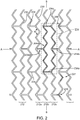
- the strengthened and toughened cylindrical, polymer tube of FIG. 1 is formed into a scaffold structure, in one embodiment a structure having a plurality of struts 230 and links 234 forming a pattern 200 as shown in FIG. 2 (pattern 200 is illustrated in a planar or flattened view), which is about the pattern for the scaffold before crimping and after the scaffold is plastically, or irreversibly deformed from its crimped state to its deployed state within a vessel by balloon expansion.
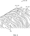
- the pattern 200 of FIG. 2 therefore, represents a tubular scaffold structure (as partially shown in three dimensional space in FIG. 3 ), so that an axis A-A is parallel to the central or longitudinal axis of the scaffold.
- the scaffold comprises a framework of struts and links that define a generally tubular body.
- the cylindrical, deformed tube of FIG. 1 may be formed into this open framework of struts and links described in FIGS. 2-3 by a laser cutting device, preferably, a pico-second green light laser that uses Helium gas as a coolant during cutting.
- the pattern 200 includes longitudinally-spaced rings 212 formed by struts 230. There are eight crowns or crests formed by the struts.
- a ring 212 is connected to an adjacent ring by no more than two links 234, each of which extends parallel to axis A-A.
- two links 234 connect the interior ring 212, which refers to a ring having a ring to its left and right in FIG. 2 , to each of the two adjacent rings.
- ring 212b is connected by two links 234 to ring 212c and two links 234 to ring 212a.
- An end ring (not shown) is an end ring connected to only one other ring.
- a ring 212 is formed by struts 230 connected at crowns 207, 209 and 210.
- a link 234 is joined with struts 230 at a crown 209 (W-crown) and at a crown 210 (Y-crown).
- a crown 207 (free-crown) does not have a link 234 connected to it.
- the struts 230 that extend from a crown 207, 209 and 210 at a constant angle from the crown center, i.e., the rings 212 are approximately zig-zag in shape, as opposed to sinusoidal for pattern 200.
- a ring 212 height which is the longitudinal distance between adjacent crowns 207 and 209/210 may be derived from the lengths of the two struts 230 connecting at the crown and a crown angle ⁇ .
- the angle ⁇ at different crowns will vary, depending on whether a link 234 is connected to a free or unconnected crown, W-crown or Y-crown.
- the zig-zag variation of the rings 212 occurs primarily about the circumference of the scaffold (i.e., along direction B-B in FIG. 2 ).
- the struts 212 centroidal axes lie primarily at about the same radial distance from the scaffold's longitudinal axis. Ideally, substantially all relative movement among struts forming rings also occurs axially, but not radially, during crimping and deployment.
- polymer scaffolds often times do not deform in this manner due to misalignments and/or uneven radial loads being applied.
- the rings 212 are capable of being collapsed to a smaller diameter during crimping and expanded to a larger diameter during deployment in a vessel.
- the pre-crimp diameter e.g., the diameter of the axially and radially expanded tube from which the scaffold is cut
- the pre-crimp diameter is always greater than, or equal to a maximum expanded scaffold diameter that the delivery balloon can, or is capable of producing when inflated.
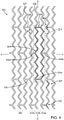
- a second embodiment of a scaffold structure has the pattern 300 illustrated in FIG. 4 .
- the pattern 300 includes longitudinally-spaced rings 312 formed by struts 330. There are twelve crests or crowns formed by the struts for each ring 312.
- a ring 312 is connected to an adjacent ring by no more than two links 334, each of which extends parallel to axis A-A.
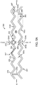
- FIGS. 5A and 5B depict aspects of the repeating pattern of closed cell elements associated with each of the patterns 300 and 200, respectively.
- FIG. 5A shows the portion of pattern 300 bounded by the phantom box VA and
- FIG. 5B shows the portion of pattern 200 bounded by the phantom box VB.
- cell 304 and cell 204 are shown in FIGS. 5A , 5B
- the vertical axis reference is indicated by the axis B-B and the longitudinal axis A-A.
- each pair of rings 212 in pattern 200 there are two such cells 204 formed by each pair of rings 212 in pattern 200, e.g., two cells 204 are formed by rings 212b and 212c and the links 234 connecting this ring pair, another two cells 204 are formed by rings 212a and 212b and the links connecting this ring pair, etc.
- there are two cells 304 formed by rings 312b and 312c and the links 334 connecting this ring pair another two cells 304 are formed by rings 312a and 312b and the links connecting this ring pair, etc..
- the space 336 of cell 304 is bounded by the longitudinally spaced rings 312b and 312c portions shown, and the circumferentially spaced and parallel links 334a and 334c connecting rings 312b and 312c.
- Links 334b and 334d extend parallel to each other and connect the cell 304 to the right and left adjacent ring in FIG. 4 , respectively.
- Link 334b connects to cell 304 at a W-crown 309.
- Link 334d connects to cell 304 at a Y-crown 310.
- a "W-crown" refers to a crown where the angle extending between a strut 330 and the link 336 at the crown 310 is an acute angle (less than 90 degrees).
- a "Y-crown” refers to a crown where the angle extending between a strut 330 and the link 334 at the crown 309 is an obtuse angle (greater than 90 degrees).
- the same definitions for Y-crown and W-crown also apply to the cell 204.
- Additional aspects of the cell 304 of FIG. 5A include angles for the respective crowns 307, 309 and 310. Those angles are identified in FIG. 6A .
- the struts 330 have strut widths 363 and strut lengths 364, and the links 334 have link widths 363.
- Each of the rings 312 has a ring height 365.
- the radii at the crowns are, in general, not equal to each other.
- the radii of the crowns are identified in FIG. 6A .
- Cell 304 of pattern 300 may be regarded as a symmetric cell, by virtue of it always having two U-crowns on each side of a W-crown and Y-crown as shown.
- the space 236 of cell 204 is bounded by the portions of longitudinally spaced rings 212b and 212c as shown, and the circumferentially spaced and parallel links 234a and 234c connecting these rings.
- Links 234b and 234d connect the cell 204 to the right and left adjacent rings in FIG. 2 , respectively.
- Link 234b connects to cell 236 at a W-crown 209.
- Link 234d connects to cell 236 at a Y-crown 210.
- There are four crowns 207 for cell 204 which may be understood as four crowns devoid of a link 234 connected at the crown.
- Cell 204 may also be regarded as a symmetric cell, by virtue of it always having one U-crown on each side of a W-crown and Y-crown as shown.
- Additional aspects of the cell 204 of FIG. 5B include angles for the respective crowns 207, 209 and 210. Those angles are indentified in FIG. 5B as angles 267, 269 and 268, respectively associated with crowns 207, 209 and 210.
- the struts 230 have strut widths 263a and strut lengths 264
- the crowns 207, 209, 210 have crown widths 270
- the links 234 have link widths 263b.
- Each of the rings 212 has a ring height 265.
- the radii of the crowns are identified in FIG. 5A as inner radii 272 and outer radii 273.
- the V76 and V80 both have a symmetric cell design.
- a "symmetric" cell design (as shown in FIGS. 5A and 5B ) has an equal number of U-crowns on each side of a W-crown or Y-crown.
- An example of an asymmetric cell design would be the V23 scaffold pattern, as described in US2011/0190871 .
- V80 has eight crowns and two links whereas the V80 design has twelve crowns and two links. Having more crowns and therefore shorter bar arms than other designs, the V80 has a higher density of struts.
- a 60 mm V80 scaffold has 33 rings and a total of 396 ring struts/scaffold, which can be compared to a total of 216 ring struts (27 rings x 8 struts per ring)/scaffold for the V76 design, and 200 ring struts/scaffold for the V59. In-vivo tests show that with a higher density of struts there is a lower late lumen loss for the V80.
- Crimping of the scaffold includes heating the polymer material to a temperature less then, but near to the glass transition temperature of the polymer. In one embodiment the temperature of the scaffold during crimping is raised to about 5 to 10 degrees below the glass transition temperature for PLLA.
- the crimping jaws are held at the final crimp diameter for final dwell period. This method for crimping a polymer scaffold having crush recovery is advantageous to reduce recoil when the crimp jaws are released.
- the scaffold is removed from the crimper and a constraining sheath is immediately placed over the scaffold to minimize recoil. Examples of such a sheath are described in U.S. Application No. 13/118,311 ( 62571.534 ).
- TABLE 1 provides a summary of the characteristics of various scaffolds that were tested in in-vitro and in-vivo to evaluate and compare various performance characteristics, as described in FIGS. 7-22 and the description that follows.
- TABLE 1 - scaffold types Scaffold Type Pattern Wall thickness (in) Tube OD (mm) Number of crowns Links connecting adjacent rings material S-1, S-2 see US application no. 13/252,121 (docket no.
- FIGS. 7-16 show results from various in-vitro tests, which were used to compare the mechanical properties of the V76 and V62 scaffolds to the V59 scaffold (see US2011/0190871 for full description of the V59). These tests were directed towards determining the radial strength and/or stiffness, acute recoil, crush recovery, pinching stiffness, and fatigue or fracture of the scaffold after repeated loading of the scaffold.
- the scaffolds were crimped to about a 0.085 in outer diameter (within the crimper head), sterilized by E-beam radiation, then expanded to 6.4mm outer diameter using a 6.0 mm balloon prior to initiating the tests.
- the scaffold were made from PLLA and cut from a biaxial expanded tube using the process described earlier. Tests were conducted to assess the fracture toughness or number of discontinuous, cracked or broken struts appearing in the V59, V62 and V76 scaffolds under different test conditions.
- FIG. 7 compares results from a three-point bending test between the V59, V62 and V76 scaffolds.
- FIG. 8 compares results from a bending fatigue test between the V59, V62 and V76 scaffolds.
- the bending axis is considered to be random, i.e., the statistical results depict the fatigue data for a bending axis about any axis passing through and perpendicular to the bending axis of the scaffold.
- FIG. 9 compares the axial force for a 10% static compression and extension of the V76 scaffold compared to the V59 and V62 scaffolds.
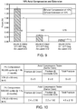
- FIG. 10 is a table showing the mean and standard deviation fractures at crowns and links for the V76 scaffold for one month and six month simulations of axial loading of the V76 scaffold when implanted within the femoral artery.
- the V76 scaffold was subjected to a 7% axial compression and extension at 37 degrees Celsius within a loaded silicon tubing simulating axial loading of the femoral artery.
- FIG.11 compares the radial strength of the V76 and V62 scaffolds to the V59 scaffold.
- FIG. 12 compares the radial stiffness of the V76 and V62 scaffolds to the V59 scaffold.
- FIG. 13 compares the acute recoil of the V76 scaffold to the V59, V2 (as described in US2011/0190871 ) and V62 scaffolds.
- FIG. 14 compares the crush-recovery of the V76 scaffold to the V59 scaffold and V62 scaffolds.
- FIG. 15 compares the deploy-to-fracture of the V76 scaffold to the V59 scaffold and V62 scaffolds. This plot shows that the V76 begins to develop critical fractures at a higher diameter than the V59.
- FIG. 16 compares the pinching stiffness of the V76 scaffold to the V59 scaffold and V62 scaffolds.
- FIG. 17 shows the total percentage of discontinuity (cracked or broken struts and links) for the V59, V62, V76, V78, V79 and V80 scaffolds after 500,000 cycles of 7% axial compression of the scaffold (equivalent to 6-month walking).
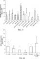
- FIGS. 18-21 compares minimum lumen diameter (MLD) or late loss and percentage of stenosis following a 28 day implant for each of the scaffold in TABLE 1.
- MLD minimum lumen diameter
- Each scaffold was implanted into the iliofemoral artery of a healthy porcine model and after 28 days explants were obtained in order to evaluate and compare the effectiveness of the polymer scaffolds in maintaining vascular patency.
- the implanted scaffolds were subject to various degrees of hip extension and flexion by the swine, which is believed to impose about 90 degrees bending, and about 3-15% axial compression of the implanted scaffold during a maximum hip and knee flexion.
- the scaffold were crimped to about a 0.085 in outer diameter (within the crimper head), sterilized by E-beam radiation, introduced into the animal model using standard procedures, then expanded within the artery to a 6.4mm outer diameter using a 6.0 mm balloon.
- the scaffold were made from PLLA (exc. V79 PLLA-PCL) and cut from a biaxial expanded tube using the process described earlier.
- FIGS. 18-21 were obtained using Quantitative Vascular Analysis (QVA) to determine the MLD and stenosis %.
- QVA Quantitative Vascular Analysis
- the number "n” in the figures represents the number of explants that were used to arrive at the mean and standard deviation values provide in FIGS. 18-21 .
- FIG. 18 counts the total number of strut discontinuities found in the explants for the V59, V62, V76, V79 and V80 scaffolds.
- FIG. 19 compares the late lumen loss or minimum lumen diameter (MLD) in the explants for the V59, V62, V76, V79 and V80 scaffolds.
- MLD minimum lumen diameter
- FIG. 20 shows late lumen loss from FIG. 19 with statistical significance indicated between scaffolds.
- TABLE 2 performance characteristics for scaffold types in TABLE 1 Scaffold Type Stenosis (28 days) (%) Late Lumen loss (28 days) (mm) Axial Fatigue % (6 months) Stiffness (N/mm) In vivo % fracture (28 days) Acute recoil (%) struts Links FIG. 21 FIG. 19 FIG. 17 FIG. 17 FIG. 16 FIG.18 FIGS.
- the high number of crests provides the V80 scaffolds with unique flexibility and as a result is more fracture resistant than the other scaffolds when axial fatigue properties are evaluated using 7% compression through 500,000 cycles (equivalent to 6-month walking).
- the low fracture rate is also well translated and shows good correlation with in-vivo testing, as demonstrated in FIG. 18 .
- V80 scaffold has more struts/scaffold-length than the other scaffolds, the struts need to be less wide and as a result the radial strength of the V80 scaffold is significantly lower than other two-link scaffolds (V76-V79).
- the V80 design would therefore appear to have a poor ability to maintain patency as compared to the other scaffolds.
- the V80 scaffold shows a significantly lower late loss than the other more radially stiff scaffolds, even where the fracture percentages and/or rates are similar, e.g., V79 compared with V80.
- the lower late loss shows statistical significance at 28 days relative to the other scaffold designs.
- the explanation for why the V80 design shows significantly lower late loss is believed to lie in the higher number of, or density of struts. With a greater number of struts the V80 provides more scaffolding (higher surface area and more support). In particular, when a strut is fracturing there is still significant support to push back the vessel.
- This aspect of the V80 may be understood in the following manner. For an equal number of fractures, there is a lower percentage of non-functioning strut-crown structures to the total number of strut-crown structures. Thus, while there may be an equal number of fractures as in other designs, the V80 is capable of providing a better or more consistent scaffolding over the vessel luminal surface because it has a larger number of intact crown-strut structures for every failed crown-strut structure.
- FIG. 21 shows that the V23-014 scaffold, which has a lower number of crowns but a higher wall thickness, produced a lower percentage of stenosis than the V80. This may be explained by an increase in the fatigue life of the scaffold struts (i.e., fewer fractures) since the thicker wall lowers the average stress for a strut for the same loading conditions.
- FIG. 22 shows acute recoil for the V78, V79, V80 and V79 scaffolds.
- a scaffold characterized as flexible, long and bioresorbable for below the knee (BTK) applications.
- CLI Critical limb ischemia
- PED peripheral disease
- Balloon expandable bare metal stents and DES self-expanding nitinol stents have been used. In either of cases, if damage is done due to an external force or there is a need to implant another stent in the distal position of the limb, the patient needs to go under surgery or lose the limb.
- the scaffold design for "BTK_01 x 100mm" is the same as V76, V78, and V79 (i.e. two link, in phase, symmetric, eight crowns).
- the design concept is symmetric, meaning there is an even number of U-crowns on either side of the linked W-V (one or two).
- the concept as shown has one U-crown on either side.
- the BTK_01 x 100mm may alternatively adopt the V80 pattern. The advantages of these designs are that they have better and more symmetric deformation during axial loading.
- ABSORB BTK uses a 'non-symmetric" 28mm length stent.
- the "BTK_01 x 100mm” design is longer (100mm as shown).
- TABLE 3 BTK scaffold ("BTK 01 x 100mm” as compared to V79 and ABSORB BTK V79 ABSORB BTK BTK_01 x 100mm Design 8C-2L.
- BTK_01 x 100mm although similar in concept to V79 (8C-2L symmetric) is cut from the same tubing as ABSORB BTK and is designed for similar artery diameters.
- BTK_01 x 100mm has a similar theoretical min crimp and max expansion diameters. A slightly larger max expansion diameter is given to accommodate for tapering along a longer vessel length.
Description
- The present invention relates to drug-eluting medical devices; more particularly, this invention relates to polymeric scaffolds that are expanded by a delivery balloon.
- Radially expandable endoprostheses are artificial devices adapted to be implanted in an anatomical lumen. An "anatomical lumen" refers to a cavity, duct, of a tubular organ such as a blood vessel, urinary tract, and bile duct. Stents are examples of endoprostheses that are generally cylindrical in shape and function to hold open and sometimes expand a segment of an anatomical lumen (one example of a stent is found in
U.S. Pat. No. 6,066,167 to Lau et al ). Stents are often used in the treatment of atherosclerotic stenosis in blood vessels. "Stenosis" refers to a narrowing or constriction of the diameter of a bodily passage or orifice. In such treatments, stents reinforce the walls of the blood vessel and prevent restenosis following angioplasty in the vascular system. "Restenosis" refers to the reoccurrence of stenosis in a blood vessel or heart valve after it has been treated (as by balloon angioplasty, stenting, or valvuloplasty) with apparent success. - The treatment of a diseased site or lesion with a stent involves both delivery and deployment of the stent. "Delivery" refers to introducing and transporting the stent through an anatomical lumen to a desired treatment site, such as a lesion. "Deployment" corresponds to expansion of the stent within the lumen at the treatment region. Delivery and deployment of a stent are accomplished by positioning the stent about one end of a catheter, inserting the end of the catheter through the skin into an anatomical lumen, advancing the catheter in the anatomical lumen to a desired treatment location, expanding the stent at the treatment location, and removing the catheter from the lumen.
- In the case of a balloon expandable stent, the stent is mounted about a balloon disposed on the catheter. Mounting the stent typically involves compressing or crimping the stent onto the balloon prior to insertion in an anatomical lumen. At the treatment site within the lumen, the stent is expanded by inflating the balloon. The balloon may then be deflated and the catheter withdrawn from the stent and the lumen, leaving the stent at the treatment site. In the case of a self-expanding stent, the stent may be secured to the catheter via a retractable sheath. When the stent is at the treatment site, the sheath may be withdrawn which allows the stent to self-expand.
- The stent must be able to satisfy a number of basic, functional requirements. The stent must be capable of withstanding the structural loads, for example, radial compressive forces, imposed on the stent as it supports the walls of a vessel after deployment. Therefore, a stent must possess adequate radial strength. After deployment, the stent must adequately maintain its size and shape throughout its service life despite the various forces that may come to bear on it. In particular, the stent must adequately maintain a vessel at a prescribed diameter for a desired treatment time despite these forces. The treatment time may correspond to the time required for the vessel walls to remodel, after which the stent is no longer necessary for the vessel to maintain a desired diameter.
- Radial strength, which is the ability of a stent to resist radial compressive forces, relates to a stent's radial yield strength and radial stiffness around a circumferential direction of the stent. A stent's "radial yield strength" or "radial strength" (for purposes of this application) may be understood as the compressive loading, which if exceeded, creates a yield stress condition resulting in the stent diameter not returning to its unloaded diameter, i.e., there is irrecoverable deformation of the stent. When the radial yield strength is exceeded the stent is expected to yield more severely and only a minimal force is required to cause major deformation.
- Even before the radial yield strength is exceeded there may be permanent deformation in the stent a following radial compressive load, but this degree of permanent deformation somewhere in the stent is not severe enough to have a significant effect on the stent's overall ability to radially support a vessel. Therefore, in some cases the art may view "radial yield strength" as the maximum radial loading, beyond which the scaffold stiffness changes dramatically. "Radial yield strength" units are sometimes force-divided-by-length, which is an expression of radial yield strength on a per-unit-length basis. Thus, for a radial yield strength per unit length, e.g., F N/mm, the radial load which, if it exceeds this value, would result in significant change in stiffness for a stent having two different lengths, L1 and L2, would therefore be the product F*L1 and F*L2, respectively. The value F, however, is the same in both cases, so that a convenient expression can be used to appreciate the radial yield strength independent of the length of the stent. Typically, the radial force that identifies the point where stiffness is lost does not change much on a per-unit-length basis when the stent length changes.
- A commonly used type of peripheral stent is the self-expanding stent made from super-elastic material, such as Nitinol. This type of material is known for its ability to return to its original configuration after severe deformation, such as a crushing load or longitudinal bending. However, this variety of self-expanding stents have undesired qualities; most notably, the high resiliency of super-elastic material produces what is commonly referred to as a "chronic outward force" (COF) on the blood vessel supported by the stent. Complications resulting from COF are discussed in Schwartz, Lewis B. et al. Does Stent Placement have a learning curve: what mistakes do we as operators have to make and how can they be avoided?, Abbott Laboratories; Abbott Park, IL, USA. It is believed that a COF exerted on a blood vessel by a self-expending stent is a main contributor to high degrees of restenosis of lesions treated by the self-expanding stent. It has been shown that not even an anti-proliferative drug delivered from drug eluting self-expandable stents can mitigate the restenosis caused by the stent's COF. Stents that are plastically deformed by a balloon to support a vessel do not suffer from this drawback. Indeed, balloon expanded stents, in contrast to self-expanding stents made from a super-elastic material, have the desirable quality of being deployable to the desired diameter for supporting the vessel without exerting residual outward forces on the vessel.
- A balloon-expanded polymer scaffold, such as that described in
US 2010/0004735 is made from a biodegradable, bioabsorbable, bioresorbable, or bioerodable polymer. The terms biodegradable, bioabsorbable, bioresorbable, biosoluble or bioerodable refer to the property of a material or stent to degrade, absorb, resorb, or erode away from an implant site. The polymer scaffold described inUS 2010/0004735 , as opposed to a metal stent, is intended to remain in the body for only a limited period of time. The scaffold is made from a biodegradable or bioerodable polymer. In many treatment applications, the presence of a stent in a body may be necessary for a limited period of time until its intended function of, for example, maintaining vascular patency and/or drug delivery is accomplished. Moreover, it has been shown that biodegradable scaffolds allow for improved healing of the anatomical lumen as compared to metal stents, which may lead to a reduced incidence of late stage thrombosis. In these cases, there is a desire to treat a vessel using a polymer scaffold, in particular a bioerodible polymer scaffold, as opposed to a metal stent, so that the prosthesis's presence in the vessel is for a limited duration. However, there are numerous challenges to overcome when developing a polymer scaffold. - The art recognizes a variety of factors that affect a polymeric scaffold's ability to retain its structural integrity and/or shape when subjected to external loadings, such as crimping and balloon expansion forces. These interactions are complex and the mechanisms of action not fully understood. According to the art, characteristics differentiating a polymeric, bio-absorbable scaffold of the type expanded to a deployed state by plastic deformation from a similarly functioning metal scaffold are many and significant. Indeed, several of the accepted analytic or empirical methods / models used to predict the behavior of metallic scaffolds tend to be unreliable, if not inappropriate, as methods / models for reliably and consistently predicting the highly non-linear, time dependent behavior of a polymeric load-bearing structure of a balloon-expandable scaffold. The models are not generally capable of providing an acceptable degree of certainty required for purposes of implanting the scaffold within a body, or predicting / anticipating the empirical data.
- Polymer material considered for use as a polymeric scaffold, e.g. poly(L-lactide) ("PLLA"), poly(L-lactide-co-glycolide) ("PLGA"), poly(D-lactide-co-glycolide) or poly(L-lactide-co-D-lactide) ("PLLA-co-PDLA") with less than 10% D-lactide, and PLLD/PDLA stereo complex, may be described, through comparison with a metallic material used to form a stent, in some of the following ways. A suitable polymer has a low strength to weight ratio, which means more material is needed to provide an equivalent mechanical property to that of a metal. Therefore, struts must be made thicker and wider to have the required strength for a stent to support lumen walls at a desired radius. The scaffold made from such polymers also tends to be brittle or have limited fracture toughness. The anisotropic and rate-dependant inelastic properties (i.e., strength / stiffness of the material varies depending upon the rate at which the material is deformed) inherent in the material, only compound this complexity in working with a polymer, particularly, bio-absorbable polymer such as PLLA or PLGA.
- Processing steps performed on, and design changes made to a metal stent that have not typically raised concerns for, or required careful attention to unanticipated changes in the average mechanical properties of the material, therefore, may not also apply to a polymer scaffold due to the non-linear and sometimes unpredictable nature of the mechanical properties of the polymer under a similar loading condition. It is sometimes the case that one needs to undertake extensive validation before it even becomes possible to predict more generally whether a particular condition is due to one factor or another - e.g., was a defect the result of one or more steps of a fabrication process, or one or more steps in a process that takes place after scaffold fabrication, e.g., crimping? As a consequence, a change to a fabrication process, post-fabrication process or even relatively minor changes to a scaffold pattern design must, generally speaking, be investigated more thoroughly than if a metallic material were used instead of the polymer. It follows, therefore, that when choosing among different polymeric scaffold designs for improvement thereof, there are far less inferences, theories, or systematic methods of discovery available, as a tool for steering one clear of unproductive paths, and towards more productive paths for improvement, than when making changes in a metal stent.
- The present inventors recognize, therefore, that, whereas inferences previously accepted in the art for stent validation or feasibility when an isotropic and ductile metallic material was used, those inferences would be inappropriate for a polymeric scaffold. A change in a polymeric scaffold pattern may affect not only the stiffness or lumen coverage of the scaffold in its deployed state supporting a lumen, but also the propensity for fractures to develop when the scaffold is crimped or being deployed. This means that, in comparison to a metallic stent, there is generally no assumption that can be made as to whether a changed scaffold pattern may not produce an adverse outcome, or require a significant change in a processing step (e.g., tube forming, laser cutting, crimping, etc.). Simply put, the highly favorable, inherent properties of a metal (generally invariant stress/strain properties with respect to the rate of deformation or the direction of loading, and the material's ductile nature), which simplify the stent fabrication process, allow for inferences to be more easily drawn between a changed stent pattern and/or a processing step and the ability for the stent to be reliably manufactured with the new pattern and without defects when implanted within a living being.
- A change in the pattern of the struts and rings of a polymeric scaffold that is plastically deformed, both when crimped to, and when later deployed by a balloon, unfortunately, is not predictable to the same or similar degree as for a metal stent. Indeed, it is recognized that unexpected problems may arise in polymer scaffold fabrication steps as a result of a changed pattern that would not have necessitated any changes if the pattern was instead formed from a metal tube. In contrast to changes in a metallic stent pattern, a change in polymer scaffold pattern may necessitate other modifications in fabrication steps or post-fabrication processing, such as crimping and sterilization.
- Scaffolds used to treat coronary vessels experience, for the most part, a primarily radial loading. However, scaffolds intended for peripheral vessels experience a quite different loading, to such an extent that the traditional measure of a stent's fitness for use, i.e., its radial strength / stiffness, is not an accurate measure of whether the scaffold will have sufficient strength to provide mechanical support within the peripheral vessel for the duration needed. This is because a peripheral scaffold is placed in a significantly different environment from a coronary scaffold. The vessel size is larger. And there is much more movement of the vessel, especially when located close to an appendage. As such, a scaffold intended for a peripheral vessel will need to be able to sustain more complex loading, including a combination of axial, bending, torsional and radial loading. See e.g. Bosiers, M. and Schwartz, L., Development of Bioresorbable Scaffolds for the Superficial Femoral Artery, SFA: CONTEMPORARY ENDOVASCULAR MANAGEMENT ('Interventions in the SFA" section). These and related challenges facing peripherally implanted stents and scaffolds are also discussed in
U.S. Application Serial No. 13/015,474 (docket no. 104584.10). - There is a need to develop a prosthesis for treating peripheral blood vessels that can maintain its structural integrity for a period of time long enough to provide a mechanical support for the vessel, until this support is no longer needed. There is a further need to develop such a prosthesis that minimizes late lumen loss and stenosis of the vessel, such as within the first month following implantation, thereby providing improved vascular patency.
- Where in the following the word invention is used and/ or features are presented as optional this should be interpreted in such a way that protection is sought for the invention as claimed. In response to these needs there is provided a peripherally-implantable and bio-erodible polymer scaffold that has a lower fracture rate, discontinuity or percentage of fractured structure. The scaffold is capable of maintaining its scaffolding support of a vessel wall sufficiently for up to about a 1, 2, and 3 month period following implantation, following which the scaffolding begins to degrade as it should no longer be needed to maintain vascular patency. Surprisingly and unexpectedly, the polymer scaffold according to one embodiment is capable of producing a significantly lower late lumen loss than prior scaffold designs about 28 days after implantation.
- According to one aspect of the invention, there is a balloon-expandable scaffold forming ring structures. Each ring is connected to adjacent rings by no more than two links and each ring has at least 8 crowns, and preferably 12 crowns formed by strut elements. The high number of crowns in the preferred embodiment is believed to provide a higher density of strut elements to support the vessel such that the surface area provided to support the vessel increases over a scaffold having fewer crowns. Additionally, for the same number of cracks or fractures occurring in the scaffold (as compared to a scaffold having fewer crowns) the overall percentage of cracks at crowns is reduced. It is believed that this combination of increased supporting surface area for the vessel walls and lower percentage of cracked to un-cracked or functional crowns is a significant factor contributing to a reduction in late lumen loss and reduced stenosis of the vessel.
- According to another aspect of the invention, a scaffold provides a desired vascular patency by increasing the surface area coverage of a scaffold at the expense of reducing the radial strength of the scaffold. In one example, a scaffold pattern is characterized by a reduced strut length and increased number of crowns for ring structures. For this scaffold an equal number of fractures as a more radial-stiff scaffold produces a lower percentage of functioning-to-nonfunctioning crown-strut structures due to a higher number of such structures as compared to the more radial stiff scaffold.
- According to another aspect of the invention, there is provided a scaffold having at most two links connecting adjacent ring structure and with or without an increased number of crowns to extend the scaffold's fatigue life during the period of time when the scaffold is needed to provide mechanical support to the vessel, e.g., during the first about one, two or three months following implantation. Tests have revealed that for a peripherally-implanted scaffold, particularly for scaffold located within arteries of appendages, failure in the scaffold structure has most often occurred due to repeated axial compression/extension and bending. Although the scaffold is in general subjected to a complex and time-varying combination of radial, axial, bending and torsion loads, it has been found that prior scaffold designs have been mostly susceptible to crack formation due to repeated cyclic axial and bending loads, e.g., 500,000 cycles of 7% axial compression / extension, which is considered equivalent to walking over a six month period. Repeated impacts between ring structures, longitudinal buckling (bending) of links or other behavior that may result from a reduction of axial and bending stiffness were not found to have a significant negative impact on vessel support or scaffold integrity based on in-vivo studies.
- As an example of bending-induced fractures, an earlier design - the V59, which is described in
WO2011094621 - showed by comparison many more fractures during bending fatigue tests (90 degree bending at 1 Hz underwater at 37 Deg. Celsius) up 1.7 million cycles. The cause for these failures was the scaffold being too stiff in bending, or its fracture toughness in bending not adequate for the test loading environment. The V59 has four links connecting adjacent ring structures. When a two link design is used, e.g., the V76 or V80, the same testing revealed substantially less fractures. - Again, the actual in-vivo loading environment is quite complex, involving axial, bending, torsion and radial loads. However, it was revealed through separate bending and axial loading bench tests for a four link verses a two link design compared to in-vivo data that when both bending and axial loading induced fractures were reduced in the bench tests, the fracture count of explanted scaffolds was also reduced significantly for the two verses four link scaffolds. This indicates that it is not so much the radial loading, but other loading not typically associated with critical stent mechanical functioning that is a key driver for balloon-expandable and peripherally-implantable scaffold design.
- According to one embodiment, a peripherally-implanted medical device includes a balloon-expanded scaffold formed from a radially expanded polymer tube, the scaffold forming a network of rings interconnected by links, including at least 8 or 12 crowns per ring, and at most 2 links connecting substantially all pairs of adjacent rings, wherein for any ring of the scaffold there are an equal number of unsupported crowns on each side of each crown connected to a link. The two links allows the structure to better absorb / distribute stresses induced during combined axial loading and bending. Moreover, it was found that the structure's overall fatigue life is significantly increased when two links are used. Additionally, symmetry of the crowns or crests about a link helps to more equally distribute stresses, or reduce stress concentrations near crowns to improve fatigue life during axial loading and bending.
- According to another aspect of invention, there is a method of treating a peripheral vessel including implanting a polymer scaffold at the vessel site, the scaffold having a network of rings interconnected by links, including 12 crowns per ring, and at most 2 links connecting substantially all pairs of adjacent rings, wherein the scaffold produces a substantially reduced late lumen loss after 28 days. For example the late lumen loss is about 0.4 mm or less than 1 mm for a 5-6 mm average vessel size. Clinically this is expected to result in in-stent late loss of at most 0.5 mm at 6-9 months in the SFA, compared to about 0.4 - 0.6 mm for the sirolimus eluting SMART stent or >1.0 mm for bare metal stents.
-
-
FIG. 1 is a perspective view of a deformed polymer tube. The tube is formed into a scaffold. -
FIG. 2 is a partial planar view of a scaffold pattern according to a first embodiment of a scaffold. -
FIG. 3 is a partial perspective view of a scaffold structure. -
FIG. 4 is a partial planar view of a scaffold pattern according to a second embodiment of a scaffold. -
FIG. 5A is a planar view of a portion of the scaffold pattern ofFIG. 4 taken at section VA-VA. -
FIG. 5B is a planar view of a portion of the scaffold pattern ofFIG. 2 taken at section VB-VB. -
FIGS. 6A and6B are tables showing examples of scaffold features in accordance with aspects of the disclosure. -
FIG. 7 compares results from a three-point bending test of a V76 scaffold design to a V62 scaffold and the V59 scaffold described inWO2011094621 . -
FIG. 8 compares results from a bending fatigue test among the V76, V62 and V59 scaffolds. -
FIG. 9 compares the axial force among the V76, V62 and V59 scaffolds for a 10% static compression and extension. -
FIG. 10 shows a mean and standard deviation fractures at crowns and links for the V76 scaffold for one month and six month simulations of axial loading of the V76 scaffold when contained within a model of the femoral artery. -
FIG.11 compares the radial strength among the V76, V62 and V59 scaffolds. -
FIG. 12 compares the radial stiffness among the V76, V62 and V59 scaffolds. -
FIG. 13 compares the acute recoil of the V76 scaffold to the V59 and V62 scaffold, and the V2 scaffold described inWO2011094621 . -
FIG. 14 compares the crush-recovery among the V76, V62 and V59 scaffolds. -
FIG. 15 compares the deploy-to-fracture among the V76, V62 and V59 scaffolds. This plot shows that the V76 begins to develop critical fractures at a higher diameter than the V59. -
FIG. 16 compares the pinching stiffness among the V76, V62 and V59 scaffolds. -
FIG. 17 compares the percentage of discontinuities, fractures or failures of struts and links among several scaffold designs having different numbers of crowns and/or links connecting ring structures. -
FIG. 18 counts the total number of discontinuities, fractures or failures of struts and links among the several scaffold designs fromFIG. 17 . -
FIG. 19 compares the in-vivo late lumen loss among several scaffold designs after 28 days implantation. -
FIG. 20 provides statistical significance values (t-test) for the late lumen loss inFIG. 19 . -
FIG. 21 compares the percentage diameter stenosis 28 days following implantation for different scaffolds. -
FIG. 22 compares the acute recoil percentage for several different scaffolds. - The disclosure proceeds as follows. First, definitions of terms that may be used during the course of the subsequent disclosure are explained. Embodiments of processes for forming a deformed polymer tube from a precursor are provided. According to the disclosure, the crush recoverable and balloon expandable scaffold is cut from a tube (
FIG. 1 ) formed through a process intended to enhance mechanical properties of the scaffold including fracture toughness. Discussion of the scaffold patterns according to several embodiments are discussed next. Examples of the scaffold patterns are provided. During this discussion, reference is made to aspects of a scaffold found to play an important role in the stiffness, strength, crimping and deployment of a polymer scaffold. Finally, bench and in-vivo test results are discussed, including exemplary examples of embodiments of invention and explanation of the results observed and problems overcome. In these examples there may be gained a further appreciation of aspects of invention - a balloon-expandable polymer scaffold having increased flexibility and lower fracture rates or percentage in peripheral arteries, and a lower late lumen loss. - For purposes of this disclosure, the following terms and definitions apply:
- "Reference vessel diameter" (RVD) is the diameter of a vessel in areas adjacent to a diseased section of a vessel that appear either normal or only minimally diseased.
- "Minimal lumen diameter" (MLD) is the diameter of a diseased section of a vessel at the site of maximal reduction in the diameter.
- % "Diameter restenosis" (%DS) is the percent difference between the reference vessel diameter and the minimal lumen diameter: (RVD - MLD)/RVD
- "Acute gain" is defined as the difference between pre- and post- procedural minimal lumen diameter.
- "Late loss" is defined as the difference between minimal luminal diameter after the procedure or post-percutaneous coronary intervention (PCI) and minimal luminal diameter at follow-up.
- "Acute Recoil" is defined as the percentage decrease in scaffold diameter within the first about ½ hour following implantation within a vessel.
- "Inflated diameter" or "expanded diameter" refers to the maximum diameter the scaffold attains when its supporting balloon is inflated to expand the scaffold from its crimped configuration to implant the scaffold within a vessel. The inflated diameter may refer to a post-dilation diameter which is beyond the nominal balloon diameter, e.g., a 6.5 mm semi-compliant PEBAX balloon has about a 7.4 mm post-dilation diameter. The scaffold diameter, after attaining its inflated diameter by balloon pressure, will to some degree decrease in diameter due to recoil effects and/or compressive forces imposed by the wall of the vessel after the balloon is removed.
- The glass transition temperature (referred to herein as "Tg") is the temperature at which the amorphous domains of a polymer change from a brittle vitreous state to a solid deformable or ductile state at atmospheric pressure. In other words, Tg corresponds to the temperature where the onset of segmental motion in the chains of the polymer occurs. Tg of a given polymer can be dependent on the heating rate and can be influenced by the thermal history of the polymer. Furthermore, the chemical structure of the polymer heavily influences the glass transition by affecting mobility of polymer chains.
- "Stress" refers to force per unit area, as in the force acting through a small area within a plane within a subject material. Stress can be divided into components, normal and parallel to the plane, called normal stress and shear stress, respectively. Tensile stress, for example, is a normal component of stress that leads to expansion (increase in length) of the subject material. In addition, compressive stress is a normal component of stress resulting in compaction (decrease in length) of the subject material.
- "Strain" refers to the amount of expansion or compression that occurs in a material at a given stress or load. Strain may be expressed as a fraction or percentage of the original length, i.e., the change in length divided by the original length. Strain, therefore, is positive for expansion and negative for compression.
- "Modulus" may be defined as the ratio of a component of stress or force per unit area applied to a material divided by the strain along an axis of applied force that result from the applied force. For example, a material has both a tensile and a compressive modulus.
- "Toughness", or "fracture toughness" is the amount of energy absorbed prior to fracture, or equivalently, the amount of work required to fracture a material. One measure of toughness is the area under a stress-strain curve from zero strain to the strain at fracture. The stress is proportional to the tensile force on the material and the strain is proportional to its length. The area under the curve then is proportional to the integral of the force over the distance the polymer stretches before breaking. This integral is the work (energy) required to break the sample. The toughness is a measure of the energy a sample can absorb before it breaks. There is a difference between toughness and strength. A material that is strong, but not tough is said to be brittle. Brittle materials are strong, but cannot deform very much before breaking.
- As used herein, the terms "axial" and "longitudinal" are used interchangeably and refer to a direction, orientation, or line that is parallel or substantially parallel to the central axis of a stent or the central axis of a tubular construct. The term "circumferential" refers to the direction along a circumference of the stent or tubular construct. The term "radial" refers to a direction, orientation, or line that is perpendicular or substantially perpendicular to the central axis of the stent or the central axis of a tubular construct and is sometimes used to describe a circumferential property, i.e radial strength.
- The term "crush recovery" is used to describe how the scaffold recovers from a pinch or crush load, while the term "crush resistance" is used to describe the force required to cause a permanent deformation of a scaffold. A scaffold or stent that does not possess good crush recovery does not substantially return to its original diameter following removal of a crushing force. As noted earlier, a scaffold or stent having a desired radial force can have an unacceptable crush recovery. And a scaffold or stent having a desired crush recovery can have an unacceptable radial force. Crush recovery and crush resistance aspects of scaffolds is described in greater detail in
US20110190871 . - The polymer scaffold illustrated in
FIG. 2 is formed from a poly(L-lactide) ("PLLA") tube. The process for forming this PLLA tube may be the process described inU.S. Patent Application No. 12/558,105 (docket no. 62571.382). Reference is made to a precursor that is "deformed" in order to produce the tube ofFIG. 1 having the desired scaffold diameter, thickness and material properties as set forth below. Before the tube is deformed or, in some embodiments, expanded to produce the desired properties in the starting tube for the scaffold, the precursor is formed. The precursor may be formed by an extrusion process which starts with raw PLLA resin material heated above the melt temperature of the polymer which is then extruded through a die. Then, in one example, an expansion process for forming an expanded PLLA tube includes heating a PLLA precursor above the PLLA glass transition temperature (i.e., 60-70 degrees C) but below the melt temperature (165-175 degrees C), e.g., around 110-120 degrees C. - A precursor tube is deformed in radial and axial directions by a blow molding process wherein deformation occurs progressively at a predetermined longitudinal speed along the longitudinal axis of the tube. As explained below, the deformation improves the mechanical properties of the tube before it is formed into the scaffold of
FIG. 2 . The tube deformation process is intended to orient polymer chains in radial and/or biaxial directions. The orientation or deformation causing re-alignment is performed according to a precise selection of processing parameters, e.g. pressure, heat (i.e., temperature), deformation rate, to affect material crystallinity and type of crystalline formation during the deformation process. - In an alternative embodiment the tube may be made of poly(L-lactide-co-glycolide), poly(D-lactide-co-glycolide) ("PLGA"), polycaprolactone, ("PCL), any semi-crystalline copolymers combining any of these monomers, or any blends of these polymers. Material choices for the scaffold should take into consideration the complex loading environment associated with many peripheral vessel locations, particularly those located close to limbs. Examples are described in
U.S. Patent Application No. 13/525,145 (docket no. 104584.43). - The femoral artery provides a dynamic environment for vascular implants as various forces may crush, twist, extend, or shorten the device simultaneously. The force application may vary between point load to distributed load or a combination thereof and also as a function of time. Recent results have shown that bioresorbable scaffolds made from highly crystalline PLLA can provide crush recovery without causing a permanent and constant outward radial force on the vessel. The permanent and constant outward radial force may be the cause of late clinical issues with nitinol self-expandable stents. However, a remaining challenge with bioresorbable scaffolds is to make them optimally fracture resistant as a function of time; that is, to improve their fatigue life or survivability under a variety of dynamic loading environments. There is a continuing need to improve fracture toughness for a scaffold; and in particular a peripherally implanted scaffold.
- The fracture resistance of a vascular scaffold depends not only on the design and the material, but is also the manufacturing process and deployment parameters. Therefore it is in particular necessary to have a process, design, and a delivery system that allows the scaffold to be uniformly expanded and deployed. As a consequence of non-uniform deployment the various struts and crowns of a scaffold will potentially be exposed to very different forces and motions, which has a deleterious effect on the fatigue life.
- Alternative ways to improve the fatigue properties are through introduction of axial flexibility and the use of pre-designed fracture points, in particular in the connector links. The fracture points could function as precursors of actual fractures, e.g., crazes and cracks or small dimension of fracture distributed in the implant. A distribution or pattern of cracks or crazes may dictate or inform one of an expected toughness of the scaffold when subjected to a particular loading, e.g., torsion, radial force, tensile etc. Although it is understand that, due to the generally highly non-linear relationship between crack formation and a coupled loading environment, that is, simultaneously applied and time varying bending, torsion and axial loading, such predictive methods may not be applicable to all situations.
- Alternative ways to improve the fatigue properties are through introduction of axial flexibility and the use of pre-designed fracture points, in particular, fracture points in or near connector links as discussed in greater detail below.
- For a tube of
FIG. 1 having a diameter about 7mm and a wall thickness above 200 micro-meters and more specifically a diameter of 8mm and a wall thickness of 280 micro-meters, the temperature at expansion is 235 +/- 5 degrees Fahrenheit, the expansion pressure is 110 +/- 10 psi and the expansion speed is 0.68 +/- 0.20 mm/sec. - The degree of radial expansion that the polymer tube undergoes can partially characterize the degree of induced circumferential molecular and crystal orientation as well as strength in a circumferential direction. The degree of radial expansion is quantified by a radial expansion ("RE") ratio, defined as RE Ratio = (Inside Diameter of Expanded Tube)/(Original Inside Diameter of the tube). The RE ratio can also be expressed as a percentage, defined as RE %=(RE ratio-1).times.100%. The degree of axial extension that the polymer tube undergoes can partially characterize induced axial molecular or crystal orientation as well as strength in an axial direction. The degree of axial extension is quantified by an axial extension ("AE") ratio, defined as AE Ratio = (Length of Extended Tube)/(Original Length of the Tube). The AE ratio can also be expressed as a percentage, defined as AE % = (AE ratio-1).times.100%. In a preferred embodiment the RE is about 400% and the AE is 40-50%.
- The strengthened and toughened cylindrical, polymer tube of
FIG. 1 is formed into a scaffold structure, in one embodiment a structure having a plurality ofstruts 230 andlinks 234 forming a pattern 200 as shown inFIG. 2 (pattern 200 is illustrated in a planar or flattened view), which is about the pattern for the scaffold before crimping and after the scaffold is plastically, or irreversibly deformed from its crimped state to its deployed state within a vessel by balloon expansion. The pattern 200 ofFIG. 2 , therefore, represents a tubular scaffold structure (as partially shown in three dimensional space inFIG. 3 ), so that an axis A-A is parallel to the central or longitudinal axis of the scaffold.FIG. 3 shows the scaffold in a state prior to crimping or after deployment. As can be seen fromFIG. 3 , the scaffold comprises a framework of struts and links that define a generally tubular body. The cylindrical, deformed tube ofFIG. 1 may be formed into this open framework of struts and links described inFIGS. 2-3 by a laser cutting device, preferably, a pico-second green light laser that uses Helium gas as a coolant during cutting. - Referring to
FIG. 2 , the pattern 200 includes longitudinally-spacedrings 212 formed bystruts 230. There are eight crowns or crests formed by the struts. Aring 212 is connected to an adjacent ring by no more than twolinks 234, each of which extends parallel to axis A-A. In this first embodiment of a scaffold pattern (pattern 200) twolinks 234 connect theinterior ring 212, which refers to a ring having a ring to its left and right inFIG. 2 , to each of the two adjacent rings. Thus,ring 212b is connected by twolinks 234 toring 212c and twolinks 234 toring 212a. An end ring (not shown) is an end ring connected to only one other ring. - A
ring 212 is formed bystruts 230 connected atcrowns link 234 is joined withstruts 230 at a crown 209 (W-crown) and at a crown 210 (Y-crown). A crown 207 (free-crown) does not have alink 234 connected to it. Preferably thestruts 230 that extend from acrown rings 212 are approximately zig-zag in shape, as opposed to sinusoidal for pattern 200. As such, in this embodiment aring 212 height, which is the longitudinal distance betweenadjacent crowns struts 230 connecting at the crown and a crown angle θ. In some embodiments the angle θ at different crowns will vary, depending on whether alink 234 is connected to a free or unconnected crown, W-crown or Y-crown. - The zig-zag variation of the
rings 212 occurs primarily about the circumference of the scaffold (i.e., along direction B-B inFIG. 2 ). Thestruts 212 centroidal axes lie primarily at about the same radial distance from the scaffold's longitudinal axis. Ideally, substantially all relative movement among struts forming rings also occurs axially, but not radially, during crimping and deployment. Although, as explained in greater detail, below, polymer scaffolds often times do not deform in this manner due to misalignments and/or uneven radial loads being applied. - The
rings 212 are capable of being collapsed to a smaller diameter during crimping and expanded to a larger diameter during deployment in a vessel. According to one aspect of the disclosure, the pre-crimp diameter (e.g., the diameter of the axially and radially expanded tube from which the scaffold is cut) is always greater than, or equal to a maximum expanded scaffold diameter that the delivery balloon can, or is capable of producing when inflated. - A second embodiment of a scaffold structure has the
pattern 300 illustrated inFIG. 4 . Like the pattern 200, thepattern 300 includes longitudinally-spacedrings 312 formed bystruts 330. There are twelve crests or crowns formed by the struts for eachring 312. Aring 312 is connected to an adjacent ring by no more than twolinks 334, each of which extends parallel to axis A-A. The description of the structure associated withrings 212, struts 230,links 234, and crowns 207, 209, 210 in connection withFIG. 2 , above, also applies to therespective rings 312, struts 330,links 334 andcrowns ring 312 forpattern 300. -
FIGS. 5A and5B depict aspects of the repeating pattern of closed cell elements associated with each of thepatterns 300 and 200, respectively.FIG. 5A shows the portion ofpattern 300 bounded by the phantom box VA andFIG. 5B shows the portion of pattern 200 bounded by the phantom box VB. Therein are showncell 304 andcell 204, respectively. InFIGS. 5A ,5B the vertical axis reference is indicated by the axis B-B and the longitudinal axis A-A. There are twosuch cells 204 formed by each pair ofrings 212 in pattern 200, e.g., twocells 204 are formed byrings links 234 connecting this ring pair, another twocells 204 are formed byrings cells 304 formed byrings links 334 connecting this ring pair, another twocells 304 are formed byrings - Referring to
FIG. 5A , thespace 336 ofcell 304 is bounded by the longitudinally spacedrings parallel links 334c connecting rings Links cell 304 to the right and left adjacent ring inFIG. 4 , respectively.Link 334b connects tocell 304 at a W-crown 309.Link 334d connects tocell 304 at a Y-crown 310. A "W-crown" refers to a crown where the angle extending between astrut 330 and thelink 336 at thecrown 310 is an acute angle (less than 90 degrees). A "Y-crown" refers to a crown where the angle extending between astrut 330 and thelink 334 at thecrown 309 is an obtuse angle (greater than 90 degrees). The same definitions for Y-crown and W-crown also apply to thecell 204. There are eight unconnected or "U-crowns" 307 forcell 304, which may be understood as eight crowns devoid of alink 334 connected at the crown. There are always two U-crowns between a Y-crown or W-crown for thecell 304. - Additional aspects of the
cell 304 ofFIG. 5A include angles for therespective crowns FIG. 6A . For the scaffold having thepattern 300 thestruts 330 havestrut widths 363 and strutlengths 364, and thelinks 334 havelink widths 363. Each of therings 312 has aring height 365. The radii at the crowns are, in general, not equal to each other. The radii of the crowns are identified inFIG. 6A .Cell 304 ofpattern 300 may be regarded as a symmetric cell, by virtue of it always having two U-crowns on each side of a W-crown and Y-crown as shown. - Referring to
FIG. 5B , the space 236 ofcell 204 is bounded by the portions of longitudinally spacedrings parallel links Links cell 204 to the right and left adjacent rings inFIG. 2 , respectively.Link 234b connects to cell 236 at a W-crown 209.Link 234d connects to cell 236 at a Y-crown 210. There are fourcrowns 207 forcell 204, which may be understood as four crowns devoid of alink 234 connected at the crown.Cell 204 may also be regarded as a symmetric cell, by virtue of it always having one U-crown on each side of a W-crown and Y-crown as shown. - Additional aspects of the
cell 204 ofFIG. 5B include angles for therespective crowns FIG. 5B asangles crowns struts 230 havestrut widths 263a and strutlengths 264, thecrowns links 234 havelink widths 263b. Each of therings 212 has aring height 265. The radii of the crowns are identified inFIG. 5A asinner radii 272 andouter radii 273. - The V76 and V80 both have a symmetric cell design. A "symmetric" cell design (as shown in
FIGS. 5A and5B ) has an equal number of U-crowns on each side of a W-crown or Y-crown. An example of an asymmetric cell design would be the V23 scaffold pattern, as described inUS2011/0190871 . - A significant difference between the V80 and V76 is that the V76 (as well as other designs, described below) has eight crowns and two links whereas the V80 design has twelve crowns and two links. Having more crowns and therefore shorter bar arms than other designs, the V80 has a higher density of struts. For example, a 60 mm V80 scaffold has 33 rings and a total of 396 ring struts/scaffold, which can be compared to a total of 216 ring struts (27 rings x 8 struts per ring)/scaffold for the V76 design, and 200 ring struts/scaffold for the V59. In-vivo tests show that with a higher density of struts there is a lower late lumen loss for the V80.
- Crimping of the scaffold, as detailed in
US Application No. 13/194,162 U.S. Application No. 13/118,311 (62571.534 - TABLE 1 provides a summary of the characteristics of various scaffolds that were tested in in-vitro and in-vivo to evaluate and compare various performance characteristics, as described in
FIGS. 7-22 and the description that follows.TABLE 1 - scaffold types Scaffold Type Pattern Wall thickness (in) Tube OD (mm) Number of crowns Links connecting adjacent rings material S-1, S-2 see US application no. 13/252,121 V2 .008 7 9 3 PLLA V23-008 .008 7 9 3 PLLA V23-014 .014 9 9 3 PLLA V59 .011 8 8 4 PLLA V62 .011 7 9 3 PLLA V76 .011 7 8 2 PLLA V78 .011 7 8 2 PLLA V79 .011 7 8 2 PLLA V79 .011 8 8 2 PLLA-PCL (90/10) V80 .011 7 12 2 PLLA -
FIGS. 7-16 show results from various in-vitro tests, which were used to compare the mechanical properties of the V76 and V62 scaffolds to the V59 scaffold (seeUS2011/0190871 for full description of the V59). These tests were directed towards determining the radial strength and/or stiffness, acute recoil, crush recovery, pinching stiffness, and fatigue or fracture of the scaffold after repeated loading of the scaffold. - The scaffolds were crimped to about a 0.085 in outer diameter (within the crimper head), sterilized by E-beam radiation, then expanded to 6.4mm outer diameter using a 6.0 mm balloon prior to initiating the tests. The scaffold were made from PLLA and cut from a biaxial expanded tube using the process described earlier. Tests were conducted to assess the fracture toughness or number of discontinuous, cracked or broken struts appearing in the V59, V62 and V76 scaffolds under different test conditions.
-
FIG. 7 compares results from a three-point bending test between the V59, V62 and V76 scaffolds.FIG. 8 compares results from a bending fatigue test between the V59, V62 and V76 scaffolds. For the three-point bending test and the bending fatigue test the bending axis is considered to be random, i.e., the statistical results depict the fatigue data for a bending axis about any axis passing through and perpendicular to the bending axis of the scaffold. -
FIG. 9 compares the axial force for a 10% static compression and extension of the V76 scaffold compared to the V59 and V62 scaffolds. -
FIG. 10 is a table showing the mean and standard deviation fractures at crowns and links for the V76 scaffold for one month and six month simulations of axial loading of the V76 scaffold when implanted within the femoral artery. For these tests the V76 scaffold was subjected to a 7% axial compression and extension at 37 degrees Celsius within a loaded silicon tubing simulating axial loading of the femoral artery. -
FIG.11 compares the radial strength of the V76 and V62 scaffolds to the V59 scaffold. -
FIG. 12 compares the radial stiffness of the V76 and V62 scaffolds to the V59 scaffold. -
FIG. 13 compares the acute recoil of the V76 scaffold to the V59, V2 (as described inUS2011/0190871 ) and V62 scaffolds. -
FIG. 14 compares the crush-recovery of the V76 scaffold to the V59 scaffold and V62 scaffolds. -
FIG. 15 compares the deploy-to-fracture of the V76 scaffold to the V59 scaffold and V62 scaffolds. This plot shows that the V76 begins to develop critical fractures at a higher diameter than the V59.FIG. 16 compares the pinching stiffness of the V76 scaffold to the V59 scaffold and V62 scaffolds. -
FIG. 17 shows the total percentage of discontinuity (cracked or broken struts and links) for the V59, V62, V76, V78, V79 and V80 scaffolds after 500,000 cycles of 7% axial compression of the scaffold (equivalent to 6-month walking). -
FIGS. 18-21 compares minimum lumen diameter (MLD) or late loss and percentage of stenosis following a 28 day implant for each of the scaffold in TABLE 1. Each scaffold was implanted into the iliofemoral artery of a healthy porcine model and after 28 days explants were obtained in order to evaluate and compare the effectiveness of the polymer scaffolds in maintaining vascular patency. The implanted scaffolds were subject to various degrees of hip extension and flexion by the swine, which is believed to impose about 90 degrees bending, and about 3-15% axial compression of the implanted scaffold during a maximum hip and knee flexion. - The scaffold were crimped to about a 0.085 in outer diameter (within the crimper head), sterilized by E-beam radiation, introduced into the animal model using standard procedures, then expanded within the artery to a 6.4mm outer diameter using a 6.0 mm balloon. The scaffold were made from PLLA (exc. V79 PLLA-PCL) and cut from a biaxial expanded tube using the process described earlier.
- The data in
FIGS. 18-21 were obtained using Quantitative Vascular Analysis (QVA) to determine the MLD and stenosis %. The number "n" in the figures represents the number of explants that were used to arrive at the mean and standard deviation values provide inFIGS. 18-21 . -
FIG. 18 counts the total number of strut discontinuities found in the explants for the V59, V62, V76, V79 and V80 scaffolds. -
FIG. 19 compares the late lumen loss or minimum lumen diameter (MLD) in the explants for the V59, V62, V76, V79 and V80 scaffolds. -
FIG. 20 shows late lumen loss fromFIG. 19 with statistical significance indicated between scaffolds. There is a p value of .011 (t-test) for the V80 scaffold data compared to the V59 scaffold data. Table 2, below, provides a summary of characteristics of the scaffolds. "ACL" and "CRF" indicate different locations for the in-vivo tests.TABLE 2: performance characteristics for scaffold types in TABLE 1 Scaffold Type Stenosis (28 days) (%) Late Lumen loss (28 days) (mm) Axial Fatigue % (6 months) Stiffness (N/mm) In vivo % fracture (28 days) Acute recoil (%) struts Links FIG. 21 FIG. 19 FIG. 17 FIG. 17 FIG. 16 FIG.18 FIGS. 13 and22 V2 18(ACL) 1.6 (ACL) - - 0.15* 19 2.5 V23-008 10(ACL) 1.8 (ACL) - - 0.20* 18 - V23-014 6(ACL) 1.0 (ACL) - - 0.39* - - V59 24 (CRF) /10 (ACL) 1.5 (CRF) / 2.1 (ACL) 8.1 31.7 0.54* 38 (ACL) / 28 (CRF) 3.2 V62 - - 2.3 15.7 0.34 - 3.8 V76 13 (CRF) 1.0 (CRF) 0.58 4.23 0.50 11 3.3 V78 16 1.6 0.60 0.00 - 16 4 V79 12 1.4 0.89 0.00 - 13 1 V79 (PLLA-PCL) 37 1.3 - - - 1 13 V80 12 0.4 0.00 0.00 - 8 8 - Referring to
FIG. 17 , the high number of crests provides the V80 scaffolds with unique flexibility and as a result is more fracture resistant than the other scaffolds when axial fatigue properties are evaluated using 7% compression through 500,000 cycles (equivalent to 6-month walking). The low fracture rate is also well translated and shows good correlation with in-vivo testing, as demonstrated inFIG. 18 . - Because the V80 scaffold has more struts/scaffold-length than the other scaffolds, the struts need to be less wide and as a result the radial strength of the V80 scaffold is significantly lower than other two-link scaffolds (V76-V79).
- Radial strength and stiffness are sometimes thought of as synonymous to scaffolding properties. According to this view, the V80 design would therefore appear to have a poor ability to maintain patency as compared to the other scaffolds. However, as seen in
FIG. 19 the V80 scaffold shows a significantly lower late loss than the other more radially stiff scaffolds, even where the fracture percentages and/or rates are similar, e.g., V79 compared with V80. As shown inFIG. 20 the lower late loss shows statistical significance at 28 days relative to the other scaffold designs. - While not wishing to be tied to any particular theory, the explanation for why the V80 design shows significantly lower late loss is believed to lie in the higher number of, or density of struts. With a greater number of struts the V80 provides more scaffolding (higher surface area and more support). In particular, when a strut is fracturing there is still significant support to push back the vessel. This aspect of the V80 may be understood in the following manner. For an equal number of fractures, there is a lower percentage of non-functioning strut-crown structures to the total number of strut-crown structures. Thus, while there may be an equal number of fractures as in other designs, the V80 is capable of providing a better or more consistent scaffolding over the vessel luminal surface because it has a larger number of intact crown-strut structures for every failed crown-strut structure.
-
FIG. 21 shows that the V23-014 scaffold, which has a lower number of crowns but a higher wall thickness, produced a lower percentage of stenosis than the V80. This may be explained by an increase in the fatigue life of the scaffold struts (i.e., fewer fractures) since the thicker wall lowers the average stress for a strut for the same loading conditions. -
FIG. 22 shows acute recoil for the V78, V79, V80 and V79 scaffolds. - In one embodiment there is a scaffold characterized as flexible, long and bioresorbable for below the knee (BTK) applications.
- Critical limb ischemia (CLI) represents the most severe clinical manifestation of peripheral disease (PAD). CLI is a chronic disease process that ultimately leads to limb loss left untreated and perhaps death from development of sepsis. Approximately 30% of lesions of CLI cases are confined to the BTK arteries and most procedures include more proximal femoral and popliteal segments. Disease in the tibial arteries tends to be diffuse and is usually associated with long segment stenoses and occlusions. The small caliber of the arteries, heavy calcification, slow of distal beds, and poor run-off vessels represent significant challenges to endovascular interventions. There are many angioplasty technologies such as BTK balloon angioplasty with a reasonably high technical success, Endovascular cryoplasty (Boston Scientific), Cutting balloon angioplasty, Drug-eluting balloons, Excimer laser atherectomy, rotational atherectomy are few of these techniques to name.
- Restenosis after PTA remains a problem that significantly affects mid-and long term outcomes. However, stents are not widely used in BTK vessels compared to ileofemoral diseases. The main reason is the small caliber and slow flow in these vessels increase the risk of stent thrombosis and intimal hyperplasia. The traditional indications for stenting are for bail-out after failed or unsuccessful angioplasty, such as flow limiting dissection or elastic recoil. A meta-analysis of 640 patients showed that BTK stent implantation after failed or unsuccessful balloon angioplasty was associated with favorable clinical results in patients with CLI. With advances in scaffold technology, there is increasing evidence to support primary scaffolding in CLI with BTK disease. Balloon expandable bare metal stents and DES self-expanding nitinol stents have been used. In either of cases, if damage is done due to an external force or there is a need to implant another stent in the distal position of the limb, the patient needs to go under surgery or lose the limb.
- As an example of a scaffolding for BTK, polylactic acid tubes were expanded to 3.5 mm in OD and cut into 100 mm in length pieces. The tubes were laser cut. The scaffold design for "BTK_01 x 100mm" is the same as V76, V78, and V79 (i.e. two link, in phase, symmetric, eight crowns). The design concept is symmetric, meaning there is an even number of U-crowns on either side of the linked W-V (one or two). The concept as shown has one U-crown on either side. The BTK_01 x 100mm may alternatively adopt the V80 pattern. The advantages of these designs are that they have better and more symmetric deformation during axial loading.
- Currently the ABSORB BTK uses a 'non-symmetric" 28mm length stent. The "BTK_01 x 100mm" design is longer (100mm as shown). As compared to other scaffold designs (TABLE 3):
TABLE 3: BTK scaffold ("BTK 01 x 100mm" as compared to V79 and ABSORB BTK V79 ABSORB BTK BTK_01 x 100mm Design 8C-2L. 6C-3L 8C-2L Length (mm) NA 28 100 Tubing (mm) 7.0x0279 3.5 x 0.152 3.5 x 0.152 BA Length (mm) 1.74 0.86 0.78 'Strut Width (mm) 0.300 0.165 0.130 Link Width (mm) 0.300 0.127 0.110 Inner Radius (mm) 0.18 0.31/0.07 0.10 Theor. Min Crimp (mm) 0228 1.06 1.04 Theor. Max Exp (mm) 9.60 3.87 4.25 - BTK_01 x 100mm, although similar in concept to V79 (8C-2L symmetric) is cut from the same tubing as ABSORB BTK and is designed for similar artery diameters. BTK_01 x 100mm has a similar theoretical min crimp and max expansion diameters. A slightly larger max expansion diameter is given to accommodate for tapering along a longer vessel length.
- While particular embodiments of the present invention have been shown and described, it will be obvious to those skilled in the art that changes and modifications can be made without departing from this invention in its broader aspects. Therefore, the appended claims are to encompass within their scope all such changes and modifications as fall within the scope of this invention.
Claims (15)
- A peripherally-implanted medical device, comprising:a balloon-expanded scaffold formed from a biaxially expanded polymer tube;the scaffold (300) forming a network of rings (312, 312a, 12b, 312c) interconnected by links (334, 334a, 334b, 334c,334d), characterized by includingexactly 12 crowns per ring, andat most 2 links connecting substantially all pairs of adjacent rings,wherein for any ring of the scaffold there are an equal number of unsupported crowns (307) on each side of each crown connected to a link; andwherein there is at most 1 mm of late lumen loss for a vessel having a 5-6 mm nominal lumen diameter, the late lumen loss being observable within the first month following implantation of the medical device within a peripheral vessel of the body.
- The device of Claim 1, wherein the scaffold is formed from a polymer tube having a semi-crystalline structure resulting from a process where an extruded polymer tube is radially expanded using a radial draw ratio of over 400% to produce the radially expanded tube having an average crystal size after radial expansion of less than about 10 microns.
- The device of Claim 2, where the polymer is PLLA.
- The device of Claim 1, wherein the scaffold is crimped to a 6 mm delivery balloon and is cut from a tube having at least a 7 mm outer diameter.
- The device of Claim 1, wherein the scaffold is crimped to a delivery balloon.
- The device of Claim 1, wherein the scaffold has about a 0.28 mm (0.011 in) wall thickness.
- The device of Claim 1, wherein the scaffold has a length of 100 mm and a 3.5 outer wall diameter.
- The device of Claim 1, wherein an aspect ratio (AR) of a strut width of a strut forming a ring structure to wall thickness is about 0.7.
- The device of Claim 1, wherein an aspect ratio (AR) of a connecting link width to wall thickness is about 0.7.
- The device of Claim 1, wherein a crown angle for the scaffold prior to crimping to a balloon is about 80 degrees.
- The device of Claim 1, wherein a first pair of links connecting a first and second ring are separated by 180 degrees and a second pair of links connecting the second ring to a third ring are separated by 180 degrees and disposed 90 degrees from the first pair of connecting links.
- The device of Claim 1, wherein a cell of the scaffold has two U-crowns (307) between each Y crown (310) and W crown (309) and the links forming W and Y crowns are parallel to each other.
- The device of Claim 1, wherein the scaffold is crimped to a balloon, the crimped scaffold structure being characterized by(1) the scaffold having substantially radially aligned polymer chains resulting from a biaxial expansion of the polymer tube, and(2) the scaffold being crimped from a starting or pre-crimp diameter to a diameter that is at least 2-3 times reduced from its starting diameter.
- The device of Claim 13, wherein the scaffold is made from PLLA.
- The device of Claim 13, wherein the scaffold forms crown angles of about 80 degrees before crimping and when crimped the crown angles are less than 10 degrees, or less than 5 degrees, or about zero degrees.
Applications Claiming Priority (2)
| Application Number | Priority Date | Filing Date | Title |
|---|---|---|---|
| US13/549,366 US9498359B2 (en) | 2012-07-13 | 2012-07-13 | Polymer scaffolds for peripheral vessels |
| PCT/US2013/025975 WO2014011214A1 (en) | 2012-07-13 | 2013-02-13 | Polymer scaffolds for peripheral vessels |
Publications (2)
| Publication Number | Publication Date |
|---|---|
| EP2872075A1 EP2872075A1 (en) | 2015-05-20 |
| EP2872075B1 true EP2872075B1 (en) | 2017-07-05 |
Family
ID=47790516
Family Applications (1)
| Application Number | Title | Priority Date | Filing Date |
|---|---|---|---|
| EP13707497.7A Not-in-force EP2872075B1 (en) | 2012-07-13 | 2013-02-13 | Polymer scaffolds for peripheral vessels |
Country Status (6)
| Country | Link |
|---|---|
| US (1) | US9498359B2 (en) |
| EP (1) | EP2872075B1 (en) |
| JP (1) | JP6267196B2 (en) |
| CN (1) | CN104427957B (en) |
| HK (1) | HK1208797A1 (en) |
| WO (1) | WO2014011214A1 (en) |
Families Citing this family (12)
| Publication number | Priority date | Publication date | Assignee | Title |
|---|---|---|---|---|
| US8814930B2 (en) | 2007-01-19 | 2014-08-26 | Elixir Medical Corporation | Biodegradable endoprosthesis and methods for their fabrication |
| US8968387B2 (en) * | 2012-07-23 | 2015-03-03 | Abbott Cardiovascular Systems Inc. | Shape memory bioresorbable polymer peripheral scaffolds |
| US9956097B2 (en) | 2012-10-23 | 2018-05-01 | Abbott Cardiovascular Systems Inc. | Methods for vascular restoration therapy |
| CN107155299A (en) * | 2014-06-02 | 2017-09-12 | 阿玛安斯医药私人公司 | Bioabsorbable support |
| US10207449B2 (en) | 2014-06-24 | 2019-02-19 | Cook Medical Technologies Llc | Sequential biaxial strain of semi-crystalline tubes |
| US10675387B2 (en) * | 2014-07-07 | 2020-06-09 | Meril Life Sciences Pvt. Ltd. | Multi stage radial deformation for manufacturing thin strut stent from bioabsorbable polymer |
| US9730819B2 (en) | 2014-08-15 | 2017-08-15 | Elixir Medical Corporation | Biodegradable endoprostheses and methods of their fabrication |
| US9855156B2 (en) | 2014-08-15 | 2018-01-02 | Elixir Medical Corporation | Biodegradable endoprostheses and methods of their fabrication |
| US9480588B2 (en) | 2014-08-15 | 2016-11-01 | Elixir Medical Corporation | Biodegradable endoprostheses and methods of their fabrication |
| US11622872B2 (en) | 2016-05-16 | 2023-04-11 | Elixir Medical Corporation | Uncaging stent |
| EP3457985B1 (en) | 2016-05-16 | 2021-02-17 | Elixir Medical Corporation | Uncaging stent |
| PL3700475T3 (en) * | 2018-03-29 | 2022-01-03 | Sahajanand Medical Technologies Limited | Stent |
Family Cites Families (24)
| Publication number | Priority date | Publication date | Assignee | Title |
|---|---|---|---|---|
| CA2380683C (en) | 1991-10-28 | 2006-08-08 | Advanced Cardiovascular Systems, Inc. | Expandable stents and method for making same |
| US20070073384A1 (en) * | 1995-03-01 | 2007-03-29 | Boston Scientific Scimed, Inc. | Longitudinally flexible expandable stent |
| US5925061A (en) | 1997-01-13 | 1999-07-20 | Gore Enterprise Holdings, Inc. | Low profile vascular stent |
| ES2290995T3 (en) | 1997-09-24 | 2008-02-16 | Med Institute, Inc. | RADIALLY EXPANDABLE ENDOPROTESIS. |
| AU1084101A (en) | 1999-10-14 | 2001-04-23 | United Stenting, Inc. | Stents with multilayered struts |
| AU2004281122B2 (en) | 2003-10-15 | 2010-04-15 | Kabushikikaisha Igaki Iryo Sekkei | Vessel stent feeder |
| US8597716B2 (en) | 2009-06-23 | 2013-12-03 | Abbott Cardiovascular Systems Inc. | Methods to increase fracture resistance of a drug-eluting medical device |
| US20110066222A1 (en) | 2009-09-11 | 2011-03-17 | Yunbing Wang | Polymeric Stent and Method of Making Same |
| US7731890B2 (en) | 2006-06-15 | 2010-06-08 | Advanced Cardiovascular Systems, Inc. | Methods of fabricating stents with enhanced fracture toughness |
| US8366762B2 (en) | 2004-08-31 | 2013-02-05 | Advanced Cardiovascular Systems, Inc. | Method of making a medical device with regioselective structure-property distribution |
| US7875233B2 (en) * | 2004-09-30 | 2011-01-25 | Advanced Cardiovascular Systems, Inc. | Method of fabricating a biaxially oriented implantable medical device |
| US7837726B2 (en) * | 2005-03-14 | 2010-11-23 | Abbott Laboratories | Visible endoprosthesis |
| US20060271170A1 (en) | 2005-05-31 | 2006-11-30 | Gale David C | Stent with flexible sections in high strain regions |
| US20070282433A1 (en) | 2006-06-01 | 2007-12-06 | Limon Timothy A | Stent with retention protrusions formed during crimping |
| US8211163B2 (en) | 2006-09-13 | 2012-07-03 | Boston Scientific Scimed, Inc. | Hybrid symmetrical stent designs |
| US8512392B2 (en) * | 2007-03-09 | 2013-08-20 | Boston Scientific Scimed, Inc. | Stent design with struts of various angles and stiffness |
| US8388673B2 (en) | 2008-05-02 | 2013-03-05 | Abbott Cardiovascular Systems Inc. | Polymeric stent |
| US8002817B2 (en) | 2007-05-04 | 2011-08-23 | Abbott Cardiovascular Systems Inc. | Stents with high radial strength and methods of manufacturing same |
| US20100217377A1 (en) * | 2007-10-10 | 2010-08-26 | Miv Therapeutics, Inc. | Calcium phosphate coated stents comprising cobalt chromium alloy |
| US20100174309A1 (en) * | 2008-05-19 | 2010-07-08 | Mindframe, Inc. | Recanalization/revascularization and embolus addressing systems including expandable tip neuro-microcatheter |
| US7972373B2 (en) * | 2007-12-19 | 2011-07-05 | Advanced Technologies And Regenerative Medicine, Llc | Balloon expandable bioabsorbable stent with a single stress concentration region interconnecting adjacent struts |
| US8206636B2 (en) | 2008-06-20 | 2012-06-26 | Amaranth Medical Pte. | Stent fabrication via tubular casting processes |
| US8568471B2 (en) | 2010-01-30 | 2013-10-29 | Abbott Cardiovascular Systems Inc. | Crush recoverable polymer scaffolds |
| US20120029618A1 (en) * | 2010-07-28 | 2012-02-02 | Boston Scientific Scimed, Inc. | Stent Connector Bump Design |
-
2012
- 2012-07-13 US US13/549,366 patent/US9498359B2/en active Active
-
2013
- 2013-02-13 JP JP2015521595A patent/JP6267196B2/en active Active
- 2013-02-13 WO PCT/US2013/025975 patent/WO2014011214A1/en active Application Filing
- 2013-02-13 CN CN201380037006.XA patent/CN104427957B/en active Active
- 2013-02-13 EP EP13707497.7A patent/EP2872075B1/en not_active Not-in-force
-
2015
- 2015-09-29 HK HK15109578.4A patent/HK1208797A1/en unknown
Non-Patent Citations (1)
| Title |
|---|
| None * |
Also Published As
| Publication number | Publication date |
|---|---|
| JP2015527116A (en) | 2015-09-17 |
| CN104427957A (en) | 2015-03-18 |
| EP2872075A1 (en) | 2015-05-20 |
| CN104427957B (en) | 2016-11-02 |
| HK1208797A1 (en) | 2016-03-18 |
| US9498359B2 (en) | 2016-11-22 |
| JP6267196B2 (en) | 2018-01-24 |
| WO2014011214A1 (en) | 2014-01-16 |
| US20140018903A1 (en) | 2014-01-16 |
Similar Documents
| Publication | Publication Date | Title |
|---|---|---|
| EP2872075B1 (en) | Polymer scaffolds for peripheral vessels | |
| US20220226133A1 (en) | Balloon expanded polymer stent | |
| JP6344727B2 (en) | Fabrication method of crushable polymer scaffold | |
| US11135074B2 (en) | Methods for vascular restoration therapy | |
| US9662231B2 (en) | Polymer scaffolds having enhanced axial fatigue properties | |
| US8808353B2 (en) | Crush recoverable polymer scaffolds having a low crossing profile | |
| EP2752173B1 (en) | Crush recoverable polymer stents with markers |
Legal Events
| Date | Code | Title | Description |
|---|---|---|---|
| PUAI | Public reference made under article 153(3) epc to a published international application that has entered the european phase |
Free format text: ORIGINAL CODE: 0009012 |
|
| 17P | Request for examination filed |
Effective date: 20150213 |
|
| AK | Designated contracting states |
Kind code of ref document: A1 Designated state(s): AL AT BE BG CH CY CZ DE DK EE ES FI FR GB GR HR HU IE IS IT LI LT LU LV MC MK MT NL NO PL PT RO RS SE SI SK SM TR |
|
| AX | Request for extension of the european patent |
Extension state: BA ME |
|
| DAX | Request for extension of the european patent (deleted) | ||
| REG | Reference to a national code |
Ref country code: HK Ref legal event code: DE Ref document number: 1208797 Country of ref document: HK |
|
| GRAP | Despatch of communication of intention to grant a patent |
Free format text: ORIGINAL CODE: EPIDOSNIGR1 |
|
| INTG | Intention to grant announced |
Effective date: 20161222 |
|
| GRAS | Grant fee paid |
Free format text: ORIGINAL CODE: EPIDOSNIGR3 |
|
| GRAJ | Information related to disapproval of communication of intention to grant by the applicant or resumption of examination proceedings by the epo deleted |
Free format text: ORIGINAL CODE: EPIDOSDIGR1 |
|
| GRAL | Information related to payment of fee for publishing/printing deleted |
Free format text: ORIGINAL CODE: EPIDOSDIGR3 |
|
| GRAR | Information related to intention to grant a patent recorded |
Free format text: ORIGINAL CODE: EPIDOSNIGR71 |
|
| GRAA | (expected) grant |
Free format text: ORIGINAL CODE: 0009210 |
|
| INTC | Intention to grant announced (deleted) | ||
| AK | Designated contracting states |
Kind code of ref document: B1 Designated state(s): AL AT BE BG CH CY CZ DE DK EE ES FI FR GB GR HR HU IE IS IT LI LT LU LV MC MK MT NL NO PL PT RO RS SE SI SK SM TR |
|
| INTG | Intention to grant announced |
Effective date: 20170530 |
|
| REG | Reference to a national code |
Ref country code: GB Ref legal event code: FG4D |
|
| REG | Reference to a national code |
Ref country code: CH Ref legal event code: EP |
|
| REG | Reference to a national code |
Ref country code: AT Ref legal event code: REF Ref document number: 906053 Country of ref document: AT Kind code of ref document: T Effective date: 20170715 |
|
| REG | Reference to a national code |
Ref country code: IE Ref legal event code: FG4D |
|
| REG | Reference to a national code |
Ref country code: DE Ref legal event code: R096 Ref document number: 602013023086 Country of ref document: DE |
|
| REG | Reference to a national code |
Ref country code: NL Ref legal event code: MP Effective date: 20170705 |
|
| REG | Reference to a national code |
Ref country code: AT Ref legal event code: MK05 Ref document number: 906053 Country of ref document: AT Kind code of ref document: T Effective date: 20170705 |
|
| REG | Reference to a national code |
Ref country code: LT Ref legal event code: MG4D |
|
| PG25 | Lapsed in a contracting state [announced via postgrant information from national office to epo] |
Ref country code: AT Free format text: LAPSE BECAUSE OF FAILURE TO SUBMIT A TRANSLATION OF THE DESCRIPTION OR TO PAY THE FEE WITHIN THE PRESCRIBED TIME-LIMIT Effective date: 20170705 Ref country code: LT Free format text: LAPSE BECAUSE OF FAILURE TO SUBMIT A TRANSLATION OF THE DESCRIPTION OR TO PAY THE FEE WITHIN THE PRESCRIBED TIME-LIMIT Effective date: 20170705 Ref country code: HR Free format text: LAPSE BECAUSE OF FAILURE TO SUBMIT A TRANSLATION OF THE DESCRIPTION OR TO PAY THE FEE WITHIN THE PRESCRIBED TIME-LIMIT Effective date: 20170705 Ref country code: FI Free format text: LAPSE BECAUSE OF FAILURE TO SUBMIT A TRANSLATION OF THE DESCRIPTION OR TO PAY THE FEE WITHIN THE PRESCRIBED TIME-LIMIT Effective date: 20170705 Ref country code: NL Free format text: LAPSE BECAUSE OF FAILURE TO SUBMIT A TRANSLATION OF THE DESCRIPTION OR TO PAY THE FEE WITHIN THE PRESCRIBED TIME-LIMIT Effective date: 20170705 Ref country code: SE Free format text: LAPSE BECAUSE OF FAILURE TO SUBMIT A TRANSLATION OF THE DESCRIPTION OR TO PAY THE FEE WITHIN THE PRESCRIBED TIME-LIMIT Effective date: 20170705 Ref country code: NO Free format text: LAPSE BECAUSE OF FAILURE TO SUBMIT A TRANSLATION OF THE DESCRIPTION OR TO PAY THE FEE WITHIN THE PRESCRIBED TIME-LIMIT Effective date: 20171005 |
|
| PG25 | Lapsed in a contracting state [announced via postgrant information from national office to epo] |
Ref country code: IS Free format text: LAPSE BECAUSE OF FAILURE TO SUBMIT A TRANSLATION OF THE DESCRIPTION OR TO PAY THE FEE WITHIN THE PRESCRIBED TIME-LIMIT Effective date: 20171105 Ref country code: RS Free format text: LAPSE BECAUSE OF FAILURE TO SUBMIT A TRANSLATION OF THE DESCRIPTION OR TO PAY THE FEE WITHIN THE PRESCRIBED TIME-LIMIT Effective date: 20170705 Ref country code: ES Free format text: LAPSE BECAUSE OF FAILURE TO SUBMIT A TRANSLATION OF THE DESCRIPTION OR TO PAY THE FEE WITHIN THE PRESCRIBED TIME-LIMIT Effective date: 20170705 Ref country code: BG Free format text: LAPSE BECAUSE OF FAILURE TO SUBMIT A TRANSLATION OF THE DESCRIPTION OR TO PAY THE FEE WITHIN THE PRESCRIBED TIME-LIMIT Effective date: 20171005 Ref country code: GR Free format text: LAPSE BECAUSE OF FAILURE TO SUBMIT A TRANSLATION OF THE DESCRIPTION OR TO PAY THE FEE WITHIN THE PRESCRIBED TIME-LIMIT Effective date: 20171006 Ref country code: LV Free format text: LAPSE BECAUSE OF FAILURE TO SUBMIT A TRANSLATION OF THE DESCRIPTION OR TO PAY THE FEE WITHIN THE PRESCRIBED TIME-LIMIT Effective date: 20170705 Ref country code: PL Free format text: LAPSE BECAUSE OF FAILURE TO SUBMIT A TRANSLATION OF THE DESCRIPTION OR TO PAY THE FEE WITHIN THE PRESCRIBED TIME-LIMIT Effective date: 20170705 |
|
| REG | Reference to a national code |
Ref country code: DE Ref legal event code: R097 Ref document number: 602013023086 Country of ref document: DE |
|
| PG25 | Lapsed in a contracting state [announced via postgrant information from national office to epo] |
Ref country code: RO Free format text: LAPSE BECAUSE OF FAILURE TO SUBMIT A TRANSLATION OF THE DESCRIPTION OR TO PAY THE FEE WITHIN THE PRESCRIBED TIME-LIMIT Effective date: 20170705 Ref country code: DK Free format text: LAPSE BECAUSE OF FAILURE TO SUBMIT A TRANSLATION OF THE DESCRIPTION OR TO PAY THE FEE WITHIN THE PRESCRIBED TIME-LIMIT Effective date: 20170705 Ref country code: CZ Free format text: LAPSE BECAUSE OF FAILURE TO SUBMIT A TRANSLATION OF THE DESCRIPTION OR TO PAY THE FEE WITHIN THE PRESCRIBED TIME-LIMIT Effective date: 20170705 |
|
| PLBE | No opposition filed within time limit |
Free format text: ORIGINAL CODE: 0009261 |
|
| STAA | Information on the status of an ep patent application or granted ep patent |
Free format text: STATUS: NO OPPOSITION FILED WITHIN TIME LIMIT |
|
| PG25 | Lapsed in a contracting state [announced via postgrant information from national office to epo] |
Ref country code: SM Free format text: LAPSE BECAUSE OF FAILURE TO SUBMIT A TRANSLATION OF THE DESCRIPTION OR TO PAY THE FEE WITHIN THE PRESCRIBED TIME-LIMIT Effective date: 20170705 Ref country code: IT Free format text: LAPSE BECAUSE OF FAILURE TO SUBMIT A TRANSLATION OF THE DESCRIPTION OR TO PAY THE FEE WITHIN THE PRESCRIBED TIME-LIMIT Effective date: 20170705 Ref country code: SK Free format text: LAPSE BECAUSE OF FAILURE TO SUBMIT A TRANSLATION OF THE DESCRIPTION OR TO PAY THE FEE WITHIN THE PRESCRIBED TIME-LIMIT Effective date: 20170705 Ref country code: EE Free format text: LAPSE BECAUSE OF FAILURE TO SUBMIT A TRANSLATION OF THE DESCRIPTION OR TO PAY THE FEE WITHIN THE PRESCRIBED TIME-LIMIT Effective date: 20170705 |
|
| 26N | No opposition filed |
Effective date: 20180406 |
|
| PG25 | Lapsed in a contracting state [announced via postgrant information from national office to epo] |
Ref country code: SI Free format text: LAPSE BECAUSE OF FAILURE TO SUBMIT A TRANSLATION OF THE DESCRIPTION OR TO PAY THE FEE WITHIN THE PRESCRIBED TIME-LIMIT Effective date: 20170705 |
|
| REG | Reference to a national code |
Ref country code: CH Ref legal event code: PL |
|
| PG25 | Lapsed in a contracting state [announced via postgrant information from national office to epo] |
Ref country code: MC Free format text: LAPSE BECAUSE OF FAILURE TO SUBMIT A TRANSLATION OF THE DESCRIPTION OR TO PAY THE FEE WITHIN THE PRESCRIBED TIME-LIMIT Effective date: 20170705 |
|
| REG | Reference to a national code |
Ref country code: BE Ref legal event code: MM Effective date: 20180228 |
|
| PG25 | Lapsed in a contracting state [announced via postgrant information from national office to epo] |
Ref country code: LI Free format text: LAPSE BECAUSE OF NON-PAYMENT OF DUE FEES Effective date: 20180228 Ref country code: LU Free format text: LAPSE BECAUSE OF NON-PAYMENT OF DUE FEES Effective date: 20180213 Ref country code: CH Free format text: LAPSE BECAUSE OF NON-PAYMENT OF DUE FEES Effective date: 20180228 |
|
| REG | Reference to a national code |
Ref country code: FR Ref legal event code: ST Effective date: 20181031 |
|
| PG25 | Lapsed in a contracting state [announced via postgrant information from national office to epo] |
Ref country code: FR Free format text: LAPSE BECAUSE OF NON-PAYMENT OF DUE FEES Effective date: 20180228 Ref country code: BE Free format text: LAPSE BECAUSE OF NON-PAYMENT OF DUE FEES Effective date: 20180228 |
|
| PG25 | Lapsed in a contracting state [announced via postgrant information from national office to epo] |
Ref country code: MT Free format text: LAPSE BECAUSE OF NON-PAYMENT OF DUE FEES Effective date: 20180213 |
|
| PG25 | Lapsed in a contracting state [announced via postgrant information from national office to epo] |
Ref country code: TR Free format text: LAPSE BECAUSE OF FAILURE TO SUBMIT A TRANSLATION OF THE DESCRIPTION OR TO PAY THE FEE WITHIN THE PRESCRIBED TIME-LIMIT Effective date: 20170705 |
|
| PGFP | Annual fee paid to national office [announced via postgrant information from national office to epo] |
Ref country code: GB Payment date: 20200130 Year of fee payment: 8 Ref country code: IE Payment date: 20200128 Year of fee payment: 8 Ref country code: DE Payment date: 20200115 Year of fee payment: 8 |
|
| PG25 | Lapsed in a contracting state [announced via postgrant information from national office to epo] |
Ref country code: PT Free format text: LAPSE BECAUSE OF FAILURE TO SUBMIT A TRANSLATION OF THE DESCRIPTION OR TO PAY THE FEE WITHIN THE PRESCRIBED TIME-LIMIT Effective date: 20170705 |
|
| PG25 | Lapsed in a contracting state [announced via postgrant information from national office to epo] |
Ref country code: CY Free format text: LAPSE BECAUSE OF FAILURE TO SUBMIT A TRANSLATION OF THE DESCRIPTION OR TO PAY THE FEE WITHIN THE PRESCRIBED TIME-LIMIT Effective date: 20170705 Ref country code: MK Free format text: LAPSE BECAUSE OF NON-PAYMENT OF DUE FEES Effective date: 20170705 Ref country code: HU Free format text: LAPSE BECAUSE OF FAILURE TO SUBMIT A TRANSLATION OF THE DESCRIPTION OR TO PAY THE FEE WITHIN THE PRESCRIBED TIME-LIMIT; INVALID AB INITIO Effective date: 20130213 |
|
| PG25 | Lapsed in a contracting state [announced via postgrant information from national office to epo] |
Ref country code: AL Free format text: LAPSE BECAUSE OF FAILURE TO SUBMIT A TRANSLATION OF THE DESCRIPTION OR TO PAY THE FEE WITHIN THE PRESCRIBED TIME-LIMIT Effective date: 20170705 |
|
| REG | Reference to a national code |
Ref country code: DE Ref legal event code: R119 Ref document number: 602013023086 Country of ref document: DE |
|
| GBPC | Gb: european patent ceased through non-payment of renewal fee |
Effective date: 20210213 |
|
| PG25 | Lapsed in a contracting state [announced via postgrant information from national office to epo] |
Ref country code: DE Free format text: LAPSE BECAUSE OF NON-PAYMENT OF DUE FEES Effective date: 20210901 Ref country code: IE Free format text: LAPSE BECAUSE OF NON-PAYMENT OF DUE FEES Effective date: 20210213 Ref country code: GB Free format text: LAPSE BECAUSE OF NON-PAYMENT OF DUE FEES Effective date: 20210213 |
|
| REG | Reference to a national code |
Ref country code: HK Ref legal event code: WD Ref document number: 1208797 Country of ref document: HK |