EP2868461A1 - Method for producing a spectacle lens - Google Patents
Method for producing a spectacle lens Download PDFInfo
- Publication number
- EP2868461A1 EP2868461A1 EP20140190975 EP14190975A EP2868461A1 EP 2868461 A1 EP2868461 A1 EP 2868461A1 EP 20140190975 EP20140190975 EP 20140190975 EP 14190975 A EP14190975 A EP 14190975A EP 2868461 A1 EP2868461 A1 EP 2868461A1
- Authority
- EP
- European Patent Office
- Prior art keywords
- casting
- mold
- sealing ring
- flexible membrane
- spectacle lens
- Prior art date
- Legal status (The legal status is an assumption and is not a legal conclusion. Google has not performed a legal analysis and makes no representation as to the accuracy of the status listed.)
- Granted
Links
- 238000004519 manufacturing process Methods 0.000 title claims description 31
- 238000005266 casting Methods 0.000 claims abstract description 103
- 238000007789 sealing Methods 0.000 claims abstract description 54
- 239000012528 membrane Substances 0.000 claims abstract description 39
- 239000000463 material Substances 0.000 claims abstract description 32
- 238000000034 method Methods 0.000 claims abstract description 25
- 239000011521 glass Substances 0.000 claims abstract description 20
- 238000011049 filling Methods 0.000 claims abstract description 16
- 230000002093 peripheral effect Effects 0.000 claims abstract description 15
- 238000006116 polymerization reaction Methods 0.000 claims abstract description 10
- 230000008569 process Effects 0.000 claims abstract description 10
- 238000005086 pumping Methods 0.000 claims abstract description 9
- 230000009471 action Effects 0.000 claims abstract description 4
- 238000010146 3D printing Methods 0.000 claims description 13
- 238000012805 post-processing Methods 0.000 claims description 9
- 239000000178 monomer Substances 0.000 claims description 7
- 238000007493 shaping process Methods 0.000 claims description 5
- 230000007246 mechanism Effects 0.000 claims description 4
- 238000001746 injection moulding Methods 0.000 claims description 2
- 210000004379 membrane Anatomy 0.000 description 35
- 230000003287 optical effect Effects 0.000 description 20
- 238000012545 processing Methods 0.000 description 11
- 238000000576 coating method Methods 0.000 description 10
- 238000000227 grinding Methods 0.000 description 8
- 238000013461 design Methods 0.000 description 7
- 230000000694 effects Effects 0.000 description 6
- 239000000126 substance Substances 0.000 description 6
- 230000008901 benefit Effects 0.000 description 5
- 239000004033 plastic Substances 0.000 description 5
- 229920003023 plastic Polymers 0.000 description 5
- 239000011248 coating agent Substances 0.000 description 4
- 239000011347 resin Substances 0.000 description 4
- 229920005989 resin Polymers 0.000 description 4
- 238000000137 annealing Methods 0.000 description 3
- 229920000704 biodegradable plastic Polymers 0.000 description 2
- 238000001816 cooling Methods 0.000 description 2
- 238000005516 engineering process Methods 0.000 description 2
- 229910001385 heavy metal Inorganic materials 0.000 description 2
- 239000007788 liquid Substances 0.000 description 2
- 230000013011 mating Effects 0.000 description 2
- 238000005259 measurement Methods 0.000 description 2
- 238000000465 moulding Methods 0.000 description 2
- 229920000642 polymer Polymers 0.000 description 2
- 239000007787 solid Substances 0.000 description 2
- 238000004528 spin coating Methods 0.000 description 2
- BVKZGUZCCUSVTD-UHFFFAOYSA-L Carbonate Chemical compound [O-]C([O-])=O BVKZGUZCCUSVTD-UHFFFAOYSA-L 0.000 description 1
- VYZAMTAEIAYCRO-UHFFFAOYSA-N Chromium Chemical compound [Cr] VYZAMTAEIAYCRO-UHFFFAOYSA-N 0.000 description 1
- MDNWOSOZYLHTCG-UHFFFAOYSA-N Dichlorophen Chemical compound OC1=CC=C(Cl)C=C1CC1=CC(Cl)=CC=C1O MDNWOSOZYLHTCG-UHFFFAOYSA-N 0.000 description 1
- 229920000491 Polyphenylsulfone Polymers 0.000 description 1
- 230000006978 adaptation Effects 0.000 description 1
- 239000000654 additive Substances 0.000 description 1
- 230000000996 additive effect Effects 0.000 description 1
- 239000000853 adhesive Substances 0.000 description 1
- 230000001070 adhesive effect Effects 0.000 description 1
- 229910045601 alloy Inorganic materials 0.000 description 1
- 239000000956 alloy Substances 0.000 description 1
- 239000011324 bead Substances 0.000 description 1
- 230000000903 blocking effect Effects 0.000 description 1
- 229910052804 chromium Inorganic materials 0.000 description 1
- 239000011651 chromium Substances 0.000 description 1
- 230000003749 cleanliness Effects 0.000 description 1
- 150000001875 compounds Chemical class 0.000 description 1
- 238000011109 contamination Methods 0.000 description 1
- 238000012937 correction Methods 0.000 description 1
- 238000000151 deposition Methods 0.000 description 1
- 230000008021 deposition Effects 0.000 description 1
- MTHSVFCYNBDYFN-UHFFFAOYSA-N diethylene glycol Chemical compound OCCOCCO MTHSVFCYNBDYFN-UHFFFAOYSA-N 0.000 description 1
- 230000009977 dual effect Effects 0.000 description 1
- 229920001971 elastomer Polymers 0.000 description 1
- 239000008187 granular material Substances 0.000 description 1
- 238000010438 heat treatment Methods 0.000 description 1
- 229920001903 high density polyethylene Polymers 0.000 description 1
- 239000004700 high-density polyethylene Substances 0.000 description 1
- 239000012535 impurity Substances 0.000 description 1
- 238000002347 injection Methods 0.000 description 1
- 239000007924 injection Substances 0.000 description 1
- 238000003780 insertion Methods 0.000 description 1
- 230000037431 insertion Effects 0.000 description 1
- 238000003754 machining Methods 0.000 description 1
- 238000002844 melting Methods 0.000 description 1
- 230000008018 melting Effects 0.000 description 1
- 229910001092 metal group alloy Inorganic materials 0.000 description 1
- 239000000203 mixture Substances 0.000 description 1
- 239000002105 nanoparticle Substances 0.000 description 1
- 230000010287 polarization Effects 0.000 description 1
- 238000005498 polishing Methods 0.000 description 1
- 229920000371 poly(diallyldimethylammonium chloride) polymer Polymers 0.000 description 1
- 229920000747 poly(lactic acid) Polymers 0.000 description 1
- 229920002635 polyurethane Polymers 0.000 description 1
- 239000004814 polyurethane Substances 0.000 description 1
- 230000000750 progressive effect Effects 0.000 description 1
- 238000000746 purification Methods 0.000 description 1
- 238000004064 recycling Methods 0.000 description 1
- 238000001028 reflection method Methods 0.000 description 1
- 230000002940 repellent Effects 0.000 description 1
- 239000005871 repellent Substances 0.000 description 1
- 239000005060 rubber Substances 0.000 description 1
- 239000011265 semifinished product Substances 0.000 description 1
- 239000007858 starting material Substances 0.000 description 1
- 238000003860 storage Methods 0.000 description 1
- 238000005496 tempering Methods 0.000 description 1
- 229920001169 thermoplastic Polymers 0.000 description 1
- 239000012815 thermoplastic material Substances 0.000 description 1
- 239000004416 thermosoftening plastic Substances 0.000 description 1
- 238000012546 transfer Methods 0.000 description 1
- 230000007704 transition Effects 0.000 description 1
- 238000013022 venting Methods 0.000 description 1
- 239000002351 wastewater Substances 0.000 description 1
- XLYOFNOQVPJJNP-UHFFFAOYSA-N water Substances O XLYOFNOQVPJJNP-UHFFFAOYSA-N 0.000 description 1
Images


Classifications
-
- B—PERFORMING OPERATIONS; TRANSPORTING
- B29—WORKING OF PLASTICS; WORKING OF SUBSTANCES IN A PLASTIC STATE IN GENERAL
- B29D—PRODUCING PARTICULAR ARTICLES FROM PLASTICS OR FROM SUBSTANCES IN A PLASTIC STATE
- B29D11/00—Producing optical elements, e.g. lenses or prisms
- B29D11/00009—Production of simple or compound lenses
-
- B—PERFORMING OPERATIONS; TRANSPORTING
- B29—WORKING OF PLASTICS; WORKING OF SUBSTANCES IN A PLASTIC STATE IN GENERAL
- B29C—SHAPING OR JOINING OF PLASTICS; SHAPING OF MATERIAL IN A PLASTIC STATE, NOT OTHERWISE PROVIDED FOR; AFTER-TREATMENT OF THE SHAPED PRODUCTS, e.g. REPAIRING
- B29C45/00—Injection moulding, i.e. forcing the required volume of moulding material through a nozzle into a closed mould; Apparatus therefor
- B29C45/0053—Injection moulding, i.e. forcing the required volume of moulding material through a nozzle into a closed mould; Apparatus therefor combined with a final operation, e.g. shaping
- B29C45/0055—Shaping
-
- B—PERFORMING OPERATIONS; TRANSPORTING
- B29—WORKING OF PLASTICS; WORKING OF SUBSTANCES IN A PLASTIC STATE IN GENERAL
- B29C—SHAPING OR JOINING OF PLASTICS; SHAPING OF MATERIAL IN A PLASTIC STATE, NOT OTHERWISE PROVIDED FOR; AFTER-TREATMENT OF THE SHAPED PRODUCTS, e.g. REPAIRING
- B29C45/00—Injection moulding, i.e. forcing the required volume of moulding material through a nozzle into a closed mould; Apparatus therefor
- B29C45/17—Component parts, details or accessories; Auxiliary operations
- B29C45/26—Moulds
- B29C45/37—Mould cavity walls, i.e. the inner surface forming the mould cavity, e.g. linings
- B29C45/376—Mould cavity walls, i.e. the inner surface forming the mould cavity, e.g. linings adjustable
-
- B—PERFORMING OPERATIONS; TRANSPORTING
- B29—WORKING OF PLASTICS; WORKING OF SUBSTANCES IN A PLASTIC STATE IN GENERAL
- B29D—PRODUCING PARTICULAR ARTICLES FROM PLASTICS OR FROM SUBSTANCES IN A PLASTIC STATE
- B29D11/00—Producing optical elements, e.g. lenses or prisms
- B29D11/00009—Production of simple or compound lenses
- B29D11/0048—Moulds for lenses
- B29D11/00538—Feeding arrangements
-
- B—PERFORMING OPERATIONS; TRANSPORTING
- B29—WORKING OF PLASTICS; WORKING OF SUBSTANCES IN A PLASTIC STATE IN GENERAL
- B29D—PRODUCING PARTICULAR ARTICLES FROM PLASTICS OR FROM SUBSTANCES IN A PLASTIC STATE
- B29D11/00—Producing optical elements, e.g. lenses or prisms
- B29D11/00009—Production of simple or compound lenses
- B29D11/0048—Moulds for lenses
- B29D11/00548—Moulds for lenses with surfaces formed by films
-
- B—PERFORMING OPERATIONS; TRANSPORTING
- B29—WORKING OF PLASTICS; WORKING OF SUBSTANCES IN A PLASTIC STATE IN GENERAL
- B29L—INDEXING SCHEME ASSOCIATED WITH SUBCLASS B29C, RELATING TO PARTICULAR ARTICLES
- B29L2011/00—Optical elements, e.g. lenses, prisms
- B29L2011/0016—Lenses
Definitions
- the invention relates to a casting mold for producing a spectacle lens, with an integrated block piece and a casting shell.
- the invention further relates to a sealing ring for such a casting mold, an arrangement of a casting mold according to the invention and a sealing ring according to the invention, a process for producing a casting mold according to the invention and a process for the production of spectacle lenses.
- a blank is usually first cast from a suitable plastic, which in a second production step, the so-called recipe glass production, is brought into the final shape to achieve the recipe values.
- the recipe glass production includes a machining.
- these blanks are provided only in coarse gradations in terms of diameter and curvature of the front and rear surfaces available.
- a significant material removal is usually required, it is usually about 70 wt .-% of the material of the blank machined and discarded. Recycling of this material is not possible.
- US 2011/0018150 A1 discloses a method for producing a spectacle lens in which the not yet polymerized resin is placed in a mold whose front and rear end faces are flexible and transparent.
- the script suggests the not yet cured resin Form the eye of the future spectacle wearer by means of the flexible end faces in such a way that a lens is produced with the desired correction values. It seems doubtful whether such a procedure is workable.
- WO 2006/114789 A2 discloses a mold and a sealing ring for producing a spectacle lens.
- the object of the invention is to provide a possibility for the simple and cost-effective production of spectacle lenses individually adapted to a spectacle wearer.
- Suitable materials for sealing ring and flexible membrane are, for example, rubbers and polymers.
- a mold is used to mold at least one surface (front or back surface) of a spectacle lens of a polymerizable material (monomer). It has a mold shell (usually either a front or back surface mold shell) which has a so-called optical surface.
- the optical surface is the mating surface to the front and back surfaces of the blank cast in such a mold.
- the mold has an integrated block piece. Integrated means that it is connected (preferably in one piece) to the casting mold.
- the block piece serves the temporary Connection of the casting mold (with adhering casting (or blank) with a processing machine.
- the casting shell is produced by prototyping. This means that at least the region of the casting mold that forms the optical surface (mating surface with the cast-off surface) is produced by building up the material by means of prototyping.
- Urformen referred to DIN 8580 all manufacturing processes in which a solid body is made from a formless material. It is the shape of a geometrically determined, solid body produced and created the substance cohesion.
- the starting materials used may be liquid, plastic, granular or powdery.
- a preferred sub-group of the primary forming in the context of the invention is injection molding.
- a plastic usually granules
- Its cavity determines the shape and the surface structure of the finished part.
- 3D printing is an additive manufacturing process in which the desired shape is produced exclusively by material application.
- a preferred 3D printing process is Fused Deposition Modeling (FDM), in which preferably a thermoplastic material is applied in a strand from a nozzle to form the desired structure.
- Suitable thermoplastics may include, for example, ABS, PC, PLA, HDPE and PPSU plastics be. Since the mold is preferably used as a disposable mold for producing only a single spectacle lens, preferably biodegradable plastics can be used.
- the manufacture of the spectacle lens is carried out by casting.
- the casting mold interacts with a sealing ring.
- the sealing ring together with the casting mold, forms a casting cavity, into which polymerizable material for producing a blank is introduced.
- This may be a known polymerizable material used to make spectacle lenses, exemplified by CR-39® (polyallyl diglycol carbonate (PDAC)), CR-607® and Trivex® (nitrogen-modified polyurethane) from PPG Industries, and the MR series (Thiourethane polymers) from Mitsui Chemicals.
- Suitable polymerizable compositions are familiar to the person skilled in the art.
- the flexible membrane of the sealing ring is fixed in the desired surface shape and carried out the polymerization.
- the casting mold with the molded blank is removed from the sealing ring. Subsequently, any necessary post-processing is carried out, in particular a recipe processing (recipe grinding) for the production of the finished spectacle lens.
- the filling of the polymerizable material in the casting cavity is carried out with the aid of the pumping action of flexible membrane of the sealing ring.
- the fixing of the flexible membrane of the sealing ring in the desired surface shape is preferably carried out by a shaping element, more preferably a spring tensioning element.
- Optionally required post-processing steps are preferably carried out at least in part while retaining the lens blank on the casting mold and using the integrated block piece.
- the blank is preferably produced with an area allowance of 10 mm or less, more preferably 5 mm or less, more preferably 0.2-5 mm.
- the material removal in the post-processing can be low according to the invention, it is preferably 20 wt .-% or less, more preferably 10 wt .-% or less.
- the peripheral seal forms the edge regions of the casting cavity, for casting a circular blank, it is thus circular.
- the peripheral seal sealingly engages the edges of the mold, sealing means here that the tightness is sufficient to prevent leakage of polymerizable material from the mold cavity.
- the peripheral seal may be flexible in design so that it can interact with differently shaped molds. These need not necessarily be circular, but their edge can be adapted from the outset to the desired final edge shape of the lens.
- the sealing ring has an opening for receiving a casting mold on one end face. As a rule, it is completely open on this end face, so that the circumferential seal sealingly surrounds the edge of an inserted casting mold. At the second end face it has a flexible membrane. This flexible membrane forms the boundary of the casting cavity at this end face.
- the mold with a mold shell shaped individually by 3D printing, allows to cast a lens blank with front and back surfaces that are finished and individually adapted from the outset.
- the further processing of the blank, in particular the recipe grinding on the opposite surface, can be done using the mold as a block piece.
- the substituted surface in particular the recipe grinding on the opposite surface, can be done using the mold as a block piece.
- Cast blanks must be annealed after casting in the course of cooling stress-free. In the prior art, this is usually done by storing the semi-finished products with the concave surface lying down on glass plates. Annealing may cause deformation at elevated temperature.
- the tempering of the blank can be carried out with the casting mold still attached. The blank is thereby fully supported, a deformation can not take place.
- the molds are usually used many times, so that individualization in the Togossenen surfaces are not possible or at best very limited. This means that in the subsequent recipe production usually a significant material loss of 70% or more occurs.
- An individually produced mold can be adapted to the future wearer in terms of diameter, edge shape, shape of the cast surface and thickness of the blank from the outset, so that in the subsequent processing (recipe loops) only a small material removal takes place.
- the surface cast with the mold may be the back surface or, preferably, the front surface of a spectacle lens. It may in particular be concave or convex and have a single or multiple intensity effect.
- the surface may, for example, be spherical, aspherical, toric, atorical, bifocal, trifocal or progressive.
- the casting shell and the optical surface of the casting mold can be designed, in particular, for casting a finished lens surface; in this case, it can be a prescription surface which comprises some or all prescription effects provided for the spectacle wearer.
- a frontal surface is drained with a progression effect, it can basically be a standard progression surface without adaptation to an individual user.
- a progression surface is designed as an individual progression surface in which the progression effect and / or arrangement and progression of the progression channel are adapted from the outset to the intended spectacle wearer.
- the sealing ring cooperates with a mold to form a casting cavity. Unlike in the prior art, therefore, according to the invention, only one mold is needed whose optical surface is used for casting a lens surface.
- the opposite surface of the spectacle lens is poured off according to the invention by using the flexible membrane of the sealing ring as a shaped element.
- a shaping element is provided for the flexible membrane of the sealing ring, which is preferably designed as a spring tensioning element. With this shaping element, the membrane can be brought into the desired basic shape (usually convex or concave).
- the shape for example, by a spring tensioning element is sufficiently accurate, so that on the shape of the proposed final area (usually a prescription surface) only a small material allowance of preferably between 0.2 and 5 mm is present that will be removed in the course of recipe production got to.
- the shaping element is preferably elastic, such as a spring tensioning element, so that volume changes or, in particular, shrinkage during polymerization can be automatically compensated during the polymerization.
- the surface of the spectacle lens formed by the flexible membrane must be reworked as part of a prescription production in order to achieve the desired recipe effects.
- at least some of the desired receptor effects can be provided by the individually 3D printed surface of the mold.
- the sealing ring in the region of the peripheral seal at least two inlet / outlet channels for casting material.
- these inlet / outlet channels are arranged radially outward on the circumference, more preferably approximately diametrically opposite each other, more preferably they are in the axial direction closely adjacent to that edge region the periphery facing the flexible membrane.
- the liquid resin When casting a lens blank, the liquid resin must be poured into the mold. Due to the tendency of air bubbles present in the resin to adhere to inner walls of the casting mold, in particular on the walls of the sealing ring, it is problematic to completely displace the air and, in particular, to obtain no air pockets in the edge region.
- the described aspect of the invention provides that at least two channels are present, so that filling can take place through a channel, while the trapped air escapes through the second channel. This substantially facilitates a bubble-free filling.
- the flexible membrane of the sealing ring which serves as a pumping element for filling. If the membrane, for example, by means of negative pressure moves axially away from the mold, this causes suction of casting material.
- the inlet / outlet channels may preferably be designed to be flexible and thus clampable or abdrückbar. This makes it possible to close the casting cavity in a simple manner after filling the assembly of the mold and sealing ring prior to the implementation of the polymerization.
- the inlet / outlet channels can be made very space-saving and require only little space in the axial direction.
- a particular advantage of the invention is also that very thin blanks can be annealed stress-free after casting without deformation, as they continue to be supported throughout the entire surface of the mold during this process.
- the glasses are usually stored for stress-free annealing only on the edge of the concave surface, undesirable deformations occur especially with thin glasses, which often have to be corrected by reworking during the recipe production again consuming.
- the sealing ring may be designed to receive a casting mold in different positions in such a way that casting cavities are formed with different edge heights.
- the casting mold can be inserted, for example, at different depths in the peripheral seal.
- An arrangement of casting mold and sealing ring can thus be used variably for different edge heights of blanks, preferably for edge heights of 1 to 20 mm, for example.
- the center thicknesses of glasses can thus according to the invention also be simple Can be varied manner, preferred center thicknesses may for example be between 1 and 20 mm.
- the possible casting according to the invention of glasses with low center thicknesses allows the production of strong minus glasses, which have very little surface allowance and therefore require little material removal during finishing.
- a sealing ring on the inner circumference of the peripheral seal has means for fixing a casting mold in at least one depth dimension. This may be, for example, a step on the inner circumference, which abuts against the edge of the mold and thus brings the mold and sealing ring in a defined axial position to each other. Optionally, several stages may be present on the inner circumference to allow a fixation with different depth dimensions.
- the sealing ring may additionally have an insertion bevel to facilitate assembly with a mold.
- blanks can be produced individually in a wide range of dimensions and curvatures.
- the base curves of the cast-off surfaces may be flat or curved (preferably convex) with radii preferably up to 30 mm.
- the diameters according to the invention can be, for example, between 40 and 100 mm. It can be provided meaningful and sufficiently small gradations of the diameter, so that the final lens can be produced cheaply and with little material removal on the edge.
- the gradations in diameter can be for example 5 mm, meaningful
- diameter steps may be 58, 63, 68, 73, 78 mm, and so on.
- the surface design of the casting shell can be determined in the first step. It may be a standard design, but it is preferably already an at least partially customized design, the individually adapted aspects may be for example diameter or shape of the glass, the curvature of the poured surface or individual prescription values such as a progression surface with a given progression value and course of the progression channel.
- the specified surface design is transferred to a 3D printer.
- at least the casting shell with its optical surface, but preferably the entire casting mold is produced by 3D printing. For the production of this only once to be used mold, a biodegradable plastic can be used, which facilitates the disposal of the mold after their use.
- FIG. 1 shows in cross section a mold 1 inserted into a sealing ring. 2
- the casting mold 1 has a casting shell 11, which has a casting surface or optical surface 12 designed for casting a blank.
- this optical surface 12 is concave, it may for example be a spherical surface or a rotationally symmetric aspherical surface.
- the mold 1 and in particular the mold shell 11 with the optical surface 12 are produced by 3D printing.
- the optical surface 12 has a shape and surface quality, which defines a surface of a spectacle lens during casting, which has a sufficient optical quality without further post-processing.
- This surface can be customized to the intended user and for example already have recipe values.
- the casting mold 1 has a block piece 13, which serves to connect the casting mold 1 and a blank cast onto it with processing machines for finishing the blank up to the finished spectacle lens.
- the optical surface 12 is provided with wet-chemical coatings, as described in more detail above.
- the mold 1 is inserted with its peripheral edge 14 in the circumferential seal 21 of the sealing ring 2 and is sealingly surrounded by this peripheral seal 21.
- the sealing ring 2 has a flexible membrane 22, in the region of the transition of the flexible membrane 22 in the circumferential seal 21 can be found at two diametrically opposite points of the circumference two inlet and outlet channels 23,24.
- the two channels 23,24 are also made of flexible material and can thus be closed by squeezing.
- the mold 1 can be used at different depths in the circumferential seal 21 of the sealing ring 2, so as to pour blanks with different edge heights.
- the mold shell 12 and the sealing ring 2 with the peripheral seal 21 and the flexible membrane 22 close together a casting cavity 3 a.
- the casting cavity 3 is filled with monomer (polymerizable mass).
- the filling takes place via one of the channels 23, 24, preferably the air is allowed to escape from the casting cavity 3 via the respective other channel.
- the outside of the flexible membrane 22 is subjected to negative pressure.
- FIG. 2 schematically shows a state in which the spring tensioning element 4 is already used and, as indicated at 5, the casting cavity 3 is partially filled with polymerizable mass. It should be noted that this schematically illustrated state does not occur in regular operation in practice, since the spring tensioning element 4 is usually used only after complete filling and venting of the casting cavity 3.
- the mold 1 with its concave optical surface 12 serves for molding a convex surface of a blank, this will usually be the front surface of a spectacle lens. Due to the individual production of the casting shell 12 by 3D printing, this front surface can not only be a standard surface, but rather it can already be adapted individually to the user of the spectacle lens, for example already be an individually adapted progression surface.
- the Figures 3 and 4 show a second embodiment of the invention. It largely corresponds to the first embodiment, but here the mold shell 11 is convexly formed with the optical surface 12 for casting a concave surface of a spectacle lens. As a rule, this variant will be the back surface of a spectacle lens.
- a particular advantage of the invention is that even in the mold 1 according to the embodiment in the Figures 3 and 4 an identical sealing ring 2 can be used, which cooperates with the corresponding casting mold 1.
- the flexible membrane 22 of the sealing ring 2 can be brought by a correspondingly shaped spring tensioning element 6 in a direction of the casting cavity 3 facing concave shape, so that in the embodiment of Figures 3 and 4 on the side of the flexible membrane 22 a convex-shaped spectacle lens surface is poured.
- the spectacle lens surface cast off on the side of the flexible membrane 22 will generally have an area allowance of 0.2-5 mm in order to allow a corresponding post-processing in the course of the recipe grinding.
- the surface design of the mold is determined, preferably taking into account individual requirements and / or recipe values.
- the defined surface design is used to derive and model 3D files that are transferred to a 3D printer.
- the complete casting mold 1 including the associated block piece 13 is made by 3D printing. she is in FIG. 5 shown.
- the optical surface 12 of the printed casting mold may be polished ( Fig. 6 ). Then it can be cleaned and optionally activated.
- a coating of the thus prepared optical surface with one or more wet-chemically applied layers preferably applied by means of spin-coating technology, as in Fig. 7 shown. These layers are later transferred to the blank during casting.
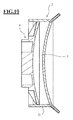
- the inlet and outlet channels 23, 24 of the sealing ring 2 are connected to the monomer supply ( Fig. 11 ).
- the thus prepared arrangement of the casting mold and sealing ring is inserted into a pumping mechanism, by means of which the flexible membrane can be subjected to negative pressure and / or overpressure.
- the casting cavity 3 is pumped down as far as possible, so the air is removed therefrom ( Fig. 12 ).
- the casting cavity is filled with monomer ( Fig. 12 and 13 ).
- the inventively provided inlet and outlet channels allow in a simple manner, the bubble-free filling.
- the outlet channel is only closed when all air bubbles are discharged.
- the inlet channel can be closed. The closing can be done by clamping, as indicated schematically in Figure 14 at 25, 26.
- the flexible membrane is fixed by means of the attached and latched spring tensioning element 4 in the desired shape ( Fig. 14 ). According to the invention, the entire process can be carried out fully automatically in an inline process which is completely completed by the environment, since the simple filling and removal of air bubbles which is possible in accordance with the invention makes such automation possible.
- the filled assembly is removed from the monomer supply and the polymerization is carried out ( Fig. 15 ).
- a polymerization cycle can last up to 48 hours and include cooling and heating phases.
- the spring tensioning element and the sealing ring are removed.
- the blank 27 remains on the casting mold according to the invention ( Fig. 16 ), the corresponding side of the blank is thus protected in the course of further processing. There is a check of the blank for cleanliness.
- a stress-free annealing of the blank ( Fig. 17 ). This remains on the mold, which supports it over the entire surface and prevents deformation even at the edge or in the middle of thin blanks.
- the mold 1 and the block piece 13 of the mold serve in the course of further processing as an interface to holding elements of machine tools or the like.
- the surface fidelity can be checked by suitable mechanical scanning methods or by reflection methods (for example the Dual Lensmapper from the company Automation & Robotics).
- the finished blanks together with the remaining casting molds can be packaged and sent for recipe grinding.
- the casting mold serves as a block piece ( Fig. 18 ). After completion of the conventionally performed recipe grinding the finished spectacle lens is separated from the mold, this is disposed of.
Abstract
Verfahren zur Herstellung eines Brillenglases, gekennzeichnet durch folgende Schritte: a) Zusammenfügen i. einer Gießform (1) mit einem integrierten Blockstück (13) und einer durch Urformen hergestellten Gießformschale (11), ii. und eines Dichtrings, der eine Umfangsdichtung (21), an einer ersten Stirnseite eine Öffnung zur Aufnahme einer Gießform, und an der zweiten Stirnseite eine flexible Membran (22) aufweist, unter Bildung eines Gießhohlraums, b) Einfüllen eines polymerisierbaren Materials in den Gießhohlraum (3) unter Zuhilfenahme einer Pumpwirkung der flexiblen Membran (22) des Dichtrings (2), c) Fixieren der flexiblen Membran (22) des Dichtrings (2) in der gewünschten Flächenform, d) Durchführen der Polymerisation, e) Entnahme der Gießform (1) mit dem angegossenen Brillenglasrohling aus dem Dichtring (2).Process for producing a spectacle lens, characterized by the following steps: a) Assembly i. a casting mold (1) with an integrated block piece (13) and a mold shell (11) produced by primary forming, ii. and a sealing ring, which has a peripheral seal (21), at a first end face an opening for receiving a casting mold, and at the second end face a flexible membrane (22), forming a casting cavity, b) filling a polymerizable material in the casting cavity (3) with the aid of a pumping action of the flexible membrane (22) of the sealing ring (2), c) fixing the flexible membrane (22) of the sealing ring (2) in the desired surface shape, d) carrying out the polymerization, e) removal of the casting mold (1) with the molded-glass lens blank from the sealing ring (2).
Description
Die Erfindung betrifft eine Gießform zur Herstellung eines Brillenglases, mit einem integrierten Blockstück und einer Gießformschale. Gegenstand der Erfindung ist ferner ein Dichtring für eine solche Gießform, eine Anordnung aus einer erfindungsgemäßen Gießform und einem erfindungsgemäßen Dichtring, ein Verfahren zur Herstellung einer erfindungsgemäßen Gießform sowie ein Verfahren zur Herstellung von Brillengläsern.The invention relates to a casting mold for producing a spectacle lens, with an integrated block piece and a casting shell. The invention further relates to a sealing ring for such a casting mold, an arrangement of a casting mold according to the invention and a sealing ring according to the invention, a process for producing a casting mold according to the invention and a process for the production of spectacle lenses.
Bei der Herstellung eines Brillenglases wird in der Regel zunächst aus einem geeigneten Kunststoff ein Rohling gegossen, der in einem zweiten Fertigungsschritt, der so genannten Rezeptglasfertigung, in die endgültige Form zur Erzielung der Rezeptwerte gebracht wird. Die Rezeptglasfertigung beinhaltet eine spanende Bearbeitung. Zur Minimierung der erforderlichen Lagerhaltung von Rohlingen werden in der Regel diese Rohlinge nur in groben Abstufungen hinsichtlich Durchmesser und Krümmung der Vorder- und Rückflächen zur Verfügung gestellt. Bei der Rezeptglasfertigung ist daher in der Regel ein erheblicher Materialabtrag erforderlich, es werden üblicherweise etwa 70 Gew.-% des Materials des Rohlings zerspant und verworfen. Ein Recycling dieses Materials ist nicht möglich.In the production of a spectacle lens, a blank is usually first cast from a suitable plastic, which in a second production step, the so-called recipe glass production, is brought into the final shape to achieve the recipe values. The recipe glass production includes a machining. In order to minimize the required storage of blanks, as a rule, these blanks are provided only in coarse gradations in terms of diameter and curvature of the front and rear surfaces available. In the recipe glass production, therefore, a significant material removal is usually required, it is usually about 70 wt .-% of the material of the blank machined and discarded. Recycling of this material is not possible.
Zur Bearbeitung des Rohlings in der Rezeptglasfertigung muss an diesem ein Blockstück angebracht werden, mittels dem der Rohling zur Bearbeitung in einer geeigneten Werkzeugmaschine gehaltert werden kann. Zum Anbringen des Rohlings an das Blockstück wird in der Regel eine niedrigschmelzende Metalllegierung verwendet. Es wird in der Regel nur ein kleiner Flächenanteil des Rohlings geblockt, da die verwendeten Schwermetalllegierungen sehr teuer sind und zudem eine sehr aufwändige Reinigung des Abwassers erforderlich ist, um dessen Kontaminierung mit Schwermetallen zu vermeiden. Die überstehenden Glasränder neigen bei der Bearbeitung zu unerwünschten Schwingungen oder zum Nachgeben und zum Bruch. Durch das Schwingen kann sich eine unerwünschte Struktur auf der Fläche ergeben, die nicht herauspoliert werden kann, da auch beim Polieren ein Schwingen und Nachgeben des Glasrandes erfolgt. Ferner wird der Außenbereich beim Bearbeiten nach unten gedrückt und schnappt nach der Belastung wieder zurück, dadurch kann sich auf der nicht bearbeiteten Rückfläche eine Art Wulst ergeben.To edit the blank in the recipe glass production must be attached to this block piece, by means of the blank can be held for processing in a suitable machine tool. To attach the blank to the block piece, a low melting metal alloy is typically used. As a rule, only a small proportion of the area of the blank is blocked, since the heavy metal alloys used are very expensive and, in addition, a very complicated purification of the waste water is required in order to avoid its contamination with heavy metals. The protruding glass edges tend during processing to undesirable vibrations or yielding and breaking. The swinging can result in an undesirable structure on the surface, which can not be polished out, since even during polishing, a swinging and yielding of the edge of the glass takes place. Furthermore, the outer area is pressed down during processing and snaps back after the load, thereby may result in a kind of bead on the non-machined rear surface.
Es ist bereits vorgeschlagen worden (
Der Erfindung liegt die Aufgabe zu Grunde, eine Möglichkeit zur einfachen und kostengünstigen Herstellung von individuell an einen Brillenträger angepassten Brillengläsern zur Verfügung zu stellen.The object of the invention is to provide a possibility for the simple and cost-effective production of spectacle lenses individually adapted to a spectacle wearer.
Gemäß einem ersten Aspekt der Erfindung wird diese Aufgabe gelöst durch ein Verfahren zur Herstellung eines Brillenglases, gekennzeichnet durch folgende Schritte:
- a. Zusammenfügen
- i. einer Gießform (1) mit einem integrierten Blockstück (13) und einer durch Urformen hergestellten Gießformschale (11),
- ii. und eines Dichtrings, der eine Umfangsdichtung (21), an einer ersten Stirnseite eine Öffnung zur Aufnahme einer Gießform, und an der zweiten Stirnseite eine flexible Membran (22) aufweist,
unter Bildung eines Gießhohlraums,
- b. Einfüllen eines polymerisierbaren Materials in den Gießhohlraum (3) unter Zuhilfenahme einer Pumpwirkung der flexiblen Membran (22) des Dichtrings (2),
- c. Fixieren der flexiblen Membran (22) des Dichtrings (2) in der gewünschten Flächenform,
- d. Durchführen der Polymerisation,
- e. Entnahme der Gießform (1) mit dem angegossenen Brillenglasrohling aus dem Dichtring (2).
- a. Put together
- i. a casting mold (1) with an integrated block piece (13) and a mold shell (11) produced by primary forming,
- ii. and a sealing ring, which has a peripheral seal (21), at a first end face an opening for receiving a casting mold, and at the second end face a flexible membrane (22),
forming a casting cavity,
- b. Filling a polymerizable material in the casting cavity (3) with the aid of a Pumping action of the flexible membrane (22) of the sealing ring (2),
- c. Fixing the flexible membrane (22) of the sealing ring (2) in the desired surface shape,
- d. Performing the polymerization,
- e. Removal of the casting mold (1) with the cast-on lens blank from the sealing ring (2).
Optional können zusätzlich ggf. erforderliche Nachbearbeitungsschritten, insbesondere Rezeptschleifen, zur Herstellung des fertigen Brillenglases, durchgeführt werden.Optionally, optionally required post-processing steps, in particular recipe loops, for the production of the finished spectacle lens, carried out.
Geeignete Materialien für Dichtring und flexible Membran sind bspw. Kautschuke und Polymere.Suitable materials for sealing ring and flexible membrane are, for example, rubbers and polymers.
Zunächst seien einige im Rahmen der Erfindung verwendete Begriffe erläutert.First, some terms used in the invention are explained.
Eine Gießform dient zum Abformen wenigstens einer Fläche (Vorder- oder Rückfläche) eines Brillenglases aus einem polymerisierbaren Material (Monomer). Sie weist eine Gießformschale (in der Regel entweder eine Vorder- oder Rückflächenformschale) auf, die eine so genannte optische Fläche aufweist. Die optische Fläche ist die Gegenfläche zu der Vorder- bzw. Rückfläche des in einer solchen Gießform gegossenen Rohlings.A mold is used to mold at least one surface (front or back surface) of a spectacle lens of a polymerizable material (monomer). It has a mold shell (usually either a front or back surface mold shell) which has a so-called optical surface. The optical surface is the mating surface to the front and back surfaces of the blank cast in such a mold.
Die Gießform weist ein integriertes Blockstück auf. Integriert bedeutet, dass es (vorzugsweise einstückig) mit der Gießform verbunden ist. Das Blockstück dient der temporären Verbindung der Gießform (mit daran anhaftenden Gießling (bzw. Rohling) mit einer Bearbeitungsmaschine.The mold has an integrated block piece. Integrated means that it is connected (preferably in one piece) to the casting mold. The block piece serves the temporary Connection of the casting mold (with adhering casting (or blank) with a processing machine.
Erfindungsgemäß ist die Gießformschale durch Urformen hergestellt. Dies bedeutet, dass wenigstens der die optische Fläche (Gegenfläche zu der abgegossenen Fläche) bildende Bereich der Gießform durch Materialaufbau mittels Urformen hergestellt ist.According to the invention, the casting shell is produced by prototyping. This means that at least the region of the casting mold that forms the optical surface (mating surface with the cast-off surface) is produced by building up the material by means of prototyping.
Urformen bezeichnet gemäß DIN 8580 alle Fertigungsverfahren, bei denen aus einem formlosen Stoff ein fester Körper hergestellt wird. Es wird dabei die Form eines geometrisch bestimmten, festen Körpers hergestellt und der Stoffzusammenhalt geschaffen. Die verwendeten Ausgangsstoffe können flüssig, plastisch, körnig oder pulverförmig sein.Urformen referred to DIN 8580 all manufacturing processes in which a solid body is made from a formless material. It is the shape of a geometrically determined, solid body produced and created the substance cohesion. The starting materials used may be liquid, plastic, granular or powdery.
Eine im Rahmen der Erfindung bevorzugte Untergruppe des Urformens ist das Spritzgießen. Bei diesem Verfahren wird ein Kunststoff (in der Regel ein Granulat) plastifiziert und in ein Spritzgießwerkzeug eingespritzt. Dessen Hohlraum bestimmt die Form und die Oberflächenstruktur des fertigen Teils.A preferred sub-group of the primary forming in the context of the invention is injection molding. In this process, a plastic (usually granules) is plasticized and injected into an injection mold. Its cavity determines the shape and the surface structure of the finished part.
Ebenfalls durchführbar ist im Rahmen der Erfindung das 3D-Drucken als eine Variante des Urformens. Beim 3D-Drucken handelt es sich um ein additives Herstellungsverfahren, bei dem die gewünschte Form ausschließlich durch Materialauftrag hergestellt wird. Ein bevorzugtes 3D-Druckverfahren ist das Fused Deposition Modeling (FDM) bei dem vorzugsweise ein thermoplastisches Material aus einer Düse zur Bildung der gewünschten Struktur strangförmig aufgetragen wird. Geeignete thermoplastische Kunststoffe können beispielsweise ABS-, PC-, PLA-, HDPE- und PPSU-Kunststoffe sein. Da die Gießform bevorzugt als Einwegform zur Herstellung lediglich eines einzigen Brillenglases verwendet wird, können bevorzugt biologisch abbaubare Kunststoffe Verwendung finden. Ebenfalls einsetzbar im Rahmen der Erfindung ist das 3D-Drucken unter Verwendung fotopolymerisierbarer, insbesondere UV-härtbarer Kunststoffe.Also feasible in the context of the invention, the 3D printing as a variant of the original molding. 3D printing is an additive manufacturing process in which the desired shape is produced exclusively by material application. A preferred 3D printing process is Fused Deposition Modeling (FDM), in which preferably a thermoplastic material is applied in a strand from a nozzle to form the desired structure. Suitable thermoplastics may include, for example, ABS, PC, PLA, HDPE and PPSU plastics be. Since the mold is preferably used as a disposable mold for producing only a single spectacle lens, preferably biodegradable plastics can be used. Also usable in the context of the invention is 3D printing using photopolymerizable, in particular UV-curable plastics.
Das Herstellen des Brillenglases erfolgt durch Gießen. Zur Bildung eines Gießhohlraums wirkt die Gießform mit einem Dichtring zusammenwirken.The manufacture of the spectacle lens is carried out by casting. To form a casting cavity, the casting mold interacts with a sealing ring.
Der Dichtring bildet zusammen mit der Gießform einen Gießhohlraum, in den polymerisierbares Material zur Herstellung eines Rohlings eingefüllt wird. Es kann sich dabei um ein bekanntes, zur Herstellung von Brillengläsern verwendetes polymerisierbares Material handeln, beispielhaft genannt seien CR-39® (Polyallyldiglycolcarbonat (PDAC)), CR-607® und Trivex® (stickstoffmodifiziertes Polyurethan) von PPG Industries sowie die MR-Serie (Thiourethanpolymere) von Mitsui Chemicals. Geeignete polymerisierbare Massen sind dem Fachmann geläufig.The sealing ring, together with the casting mold, forms a casting cavity, into which polymerizable material for producing a blank is introduced. This may be a known polymerizable material used to make spectacle lenses, exemplified by CR-39® (polyallyl diglycol carbonate (PDAC)), CR-607® and Trivex® (nitrogen-modified polyurethane) from PPG Industries, and the MR series (Thiourethane polymers) from Mitsui Chemicals. Suitable polymerizable compositions are familiar to the person skilled in the art.
Die flexible Membran des Dichtrings wird in der gewünschten Flächenform fixiert und die Polymerisation durchgeführt. Die Gießform mit dem angegossenen Rohling wird aus dem Dichtring entnommen. Anschließend wird eine gegebenenfalls erforderliche Nachbearbeitung durchgeführt, insbesondere eine Rezeptbearbeitung (Rezeptschleifen) zur Herstellung des fertigen Brillenglases.The flexible membrane of the sealing ring is fixed in the desired surface shape and carried out the polymerization. The casting mold with the molded blank is removed from the sealing ring. Subsequently, any necessary post-processing is carried out, in particular a recipe processing (recipe grinding) for the production of the finished spectacle lens.
Das Einfüllen des polymerisierbaren Materials in den Gießhohlraum erfolgt unter Zuhilfenahme der Pumpwirkung der flexiblen Membran des Dichtrings. Das Fixieren der flexiblen Membran des Dichtrings in der gewünschten Flächenform erfolgt bevorzugt durch ein formgebendes Element, weiter bevorzugt ein Federspannelement. Gegebenenfalls erforderliche Nachbearbeitungsschritte werden bevorzugt wenigstens zum Teil unter Verbleib des Brillenglasrohlings auf der Gießform und Verwendung des integrierten Blockstücks durchgeführt.The filling of the polymerizable material in the casting cavity is carried out with the aid of the pumping action of flexible membrane of the sealing ring. The fixing of the flexible membrane of the sealing ring in the desired surface shape is preferably carried out by a shaping element, more preferably a spring tensioning element. Optionally required post-processing steps are preferably carried out at least in part while retaining the lens blank on the casting mold and using the integrated block piece.
Bevorzugt wird der Rohling mit einem Flächenaufmaß von 10 mm oder weniger, weiter vorzugsweise 5 mm oder weniger, weiter vorzugsweise 0,2-5 mm hergestellt. Der Materialabtrag bei der Nachbearbeitung kann erfindungsgemäß gering ausfallen, er beträgt bevorzugt 20 Gew.-% oder weniger, weiter vorzugsweise 10 Gew.-% oder weniger.The blank is preferably produced with an area allowance of 10 mm or less, more preferably 5 mm or less, more preferably 0.2-5 mm. The material removal in the post-processing can be low according to the invention, it is preferably 20 wt .-% or less, more preferably 10 wt .-% or less.
Die Umfangsdichtung bildet die Randbereiche des Gießhohlraums, zum Gießen eines kreisförmigen Rohlings ist sie somit kreisförmig ausgebildet. Die Umfangsdichtung wirkt mit den Rändern der Gießform abdichtend zusammen, abdichtend bedeutet hier, dass die Dichtigkeit hinreichend ist, um ein Austreten von polymerisierbaren Material aus dem Gießhohlraum zu verhindern. Die Umfangsdichtung kann dergestalt flexibel ausgebildet sein, dass sie mit unterschiedlich geformten Gießformen zusammenwirken kann. Diese müssen nicht notwendigerweise kreisförmig sein, vielmehr kann ihr Rand von vornherein an die gewünschte endgültige Randform des Brillenglases angepasst sein.The peripheral seal forms the edge regions of the casting cavity, for casting a circular blank, it is thus circular. The peripheral seal sealingly engages the edges of the mold, sealing means here that the tightness is sufficient to prevent leakage of polymerizable material from the mold cavity. The peripheral seal may be flexible in design so that it can interact with differently shaped molds. These need not necessarily be circular, but their edge can be adapted from the outset to the desired final edge shape of the lens.
Der Dichtring weist an einer Stirnseite eine Öffnung zur Aufnahme einer Gießform auf. In der Regel ist er an dieser Stirnseite vollständig offen, so dass die Umfangsdichtung den Rand einer eingesetzten Gießform dichtend umfasst. An der zweiten Stirnseite weist er eine flexible Membran auf. Diese flexible Membran bildet an dieser Stirnseite die Begrenzung des Gießhohlraums.The sealing ring has an opening for receiving a casting mold on one end face. As a rule, it is completely open on this end face, so that the circumferential seal sealingly surrounds the edge of an inserted casting mold. At the second end face it has a flexible membrane. This flexible membrane forms the boundary of the casting cavity at this end face.
Die Gießform mit einer individuell durch 3D-Druck geformten Gießformschale erlaubt es, einen Brillenglasrohling mit von vornherein fertiger und individuell angepasster Vorder- oder Rückfläche zu gießen. Die weitere Bearbeitung des Rohlings, insbesondere das Rezeptschleifen auf der gegenüberliegenden Fläche, kann unter Verwendung der Gießform als Blockstück erfolgen. Über die gesamte Fertigung des Brillenglases bleibt somit die abgegossene fertige Fläche geschützt, ein nachträgliches Aufblocken von einem Blockstück für das Rezeptschleifen entfällt. Die gesamte abgegossene Fläche ist während des Fertigungsvorgangs durchgehend vollflächig geschütztThe mold, with a mold shell shaped individually by 3D printing, allows to cast a lens blank with front and back surfaces that are finished and individually adapted from the outset. The further processing of the blank, in particular the recipe grinding on the opposite surface, can be done using the mold as a block piece. Throughout the entire production of the spectacle lens thus the abgegossene finished surface remains protected, a subsequent blocking of a block piece for the recipe grinding is eliminated. The entire cast-off area is completely protected throughout the manufacturing process
Gegossene Rohlinge müssen nach dem Gießen im Zuge des Abkühlen spannungsfrei getempert werden. Im Stand der Technik erfolgt dies in der Regel durch Lagern der Halbfertigfabrikate mit der konkaven Fläche nach unten auf Glasplatten liegend. Beim Tempern kann es zu Deformationen bei der erhöhten Temperatur kommen. Erfindungsgemäß kann hingegen das Tempern des Rohlings mit der noch angeblockten Gießform erfolgen. Der Rohling wird dabei vollflächig unterstützt, eine Deformation kann nicht stattfinden.Cast blanks must be annealed after casting in the course of cooling stress-free. In the prior art, this is usually done by storing the semi-finished products with the concave surface lying down on glass plates. Annealing may cause deformation at elevated temperature. By contrast, according to the invention, the tempering of the blank can be carried out with the casting mold still attached. The blank is thereby fully supported, a deformation can not take place.
Durch die individuelle Fertigung und lediglich einmalige Verwendung einer durch 3D-Druck gefertigten Gießform ist es möglich, die abgegossene Fläche von vornherein an die individuellen Anforderungen eines Brillenträgers anzupassen. Dies beinhaltet mehrere Aspekte und Vorteile.Due to the individual production and only one use of a mold manufactured by 3D-printing, it is possible to adapt the cast-off surface from the outset to the individual requirements of a spectacle wearer. This includes several aspects and benefits.
Im Stand der Technik werden die Formen in der Regel vielfach verwendet, so dass Individualisierung in der abgegossenen Flächen nicht oder allenfalls sehr begrenzt möglich sind. Dies bedeutet, dass in der anschließenden Rezeptfertigung in der Regel ein erheblicher Materialverlust von 70 % oder mehr auftritt. Eine individuell hergestellte Gießform kann von vornherein hinsichtlich Durchmesser, Randform, Form der abgegossenen Fläche und Dicke des Rohlings an den zukünftigen Brillenträger angepasst werden, so dass in der nachfolgenden Bearbeitung (Rezeptschleifen) nur noch ein geringer Materialabtrag erfolgt.In the prior art, the molds are usually used many times, so that individualization in the abgegossenen surfaces are not possible or at best very limited. This means that in the subsequent recipe production usually a significant material loss of 70% or more occurs. An individually produced mold can be adapted to the future wearer in terms of diameter, edge shape, shape of the cast surface and thickness of the blank from the outset, so that in the subsequent processing (recipe loops) only a small material removal takes place.
Die mit der Gießform abgegossene Fläche kann die Rückfläche oder vorzugsweise die Vorderfläche eines Brillenglases sein. Sie kann insbesondere konkav oder konvex ausgebildet sein und eine Einstärken- oder Mehrstärkenwirkung aufweisen. Die Fläche kann beispielsweise sphärisch, asphärisch, torisch, atorisch, bifokal, trifokal oder als progressive Fläche ausgebildet sein.The surface cast with the mold may be the back surface or, preferably, the front surface of a spectacle lens. It may in particular be concave or convex and have a single or multiple intensity effect. The surface may, for example, be spherical, aspherical, toric, atorical, bifocal, trifocal or progressive.
Die Gießformschale und optische Fläche der Gießform kann insbesondere zum Abgießen einer fertigen Brillenglasfläche ausgebildet sein, dabei kann es sich um eine Rezeptfläche handeln, die einige oder alle für den Brillenträger vorgesehenen Rezeptwirkungen umfasst. Wird beispielsweise eine Vorderfläche mit einer Progressionswirkung abgegossen, kann es sich grundsätzlich um eine Standard-Progressionsfläche ohne Anpassung an einen individuellen Benutzer handeln. Bevorzugt ist es im Rahmen der Erfindung jedoch, wenn eine solche Progressionsfläche als individuelle Progressionsfläche ausgebildet ist, bei der Progressionswirkung und/oder Anordnung und Verlauf des Progressionskanals von vorneherein an den vorgesehenen Brillenträger angepasst sind.The casting shell and the optical surface of the casting mold can be designed, in particular, for casting a finished lens surface; in this case, it can be a prescription surface which comprises some or all prescription effects provided for the spectacle wearer. For example, if a frontal surface is drained with a progression effect, it can basically be a standard progression surface without adaptation to an individual user. In the context of the invention, however, it is preferred if such a progression surface is designed as an individual progression surface in which the progression effect and / or arrangement and progression of the progression channel are adapted from the outset to the intended spectacle wearer.
Ein weiterer Vorteil der Erfindung ist die Möglichkeit, die abgegossene Fläche des Brillenglases im Zuge des Abgießens mit verschiedenen Beschichtungen zu versehen. Vorzugsweise werden zu diesem Zweck auf die optische Fläche der Gießformschale nasschemische Beschichtungen aufgebracht, die beim Abgießen auf die entsprechende Brillenglasfläche übertragen werden. Das Auftragen nasschemischer Beschichtungen auf die optische Fläche kann bevorzugt durch geeignete Verfahren wie beispielsweise die Spin-Coating-Technologie erfolgen. Beispielsweise können solche Beschichtungen die nachfolgend aufgeführten Funktionen haben, die aufgezählt werden von außen nach innen (aus der Sicht des fertigen Brillenglases):
- Antifog-Schicht (bspw. Nanopartikel)
- Antistatik-Beschichtung
- Hydrophobierungsschicht
- Antireflexbeschichtung
- Polarisationsschicht
- Photochromschicht
- Haftvermittler zur Verbesserung der Haftung am Material des Brillenglases
- Antifogging layer (eg nanoparticles)
- Antistatic coating
- Water repellent layer
- Antireflection coating
- polarization layer
- Photo chromium layer
- Adhesive for improving the adhesion to the material of the spectacle lens
Der Dichtring wirkt mit einer Gießform zur Bildung eines Gießhohlraums zusammen. Anders als im Stand der Technik wird somit erfindungsgemäß lediglich eine Gießform benötigt, deren optische Fläche zum Abgießen einer Brillenglasfläche dient. Die gegenüberliegende Fläche des Brillenglases wird erfindungsgemäß abgegossen durch Verwendung der flexiblen Membran des Dichtrings als Formelement. Bevorzugt ist ein formgebendes Element für die flexible Membran des Dichtrings vorgesehen, das vorzugsweise als Federspannelement ausgebildet ist. Mit diesem formgebenden Element kann die Membran in die gewünschte Grundform (in der Regel konvex oder konkav) gebracht werden. Die Formgebung beispielsweise durch ein Federspannelement ist hinreichend genau, so dass über die Form der vorgesehenen endgültigen Fläche (in der Regel eine Rezeptfläche) lediglich ein geringes Materialaufmaß von bevorzugt zwischen 0,2 und 5 mm vorhanden ist, dass im Zuge der Rezeptfertigung noch abgetragen werden muss.The sealing ring cooperates with a mold to form a casting cavity. Unlike in the prior art, therefore, according to the invention, only one mold is needed whose optical surface is used for casting a lens surface. The opposite surface of the spectacle lens is poured off according to the invention by using the flexible membrane of the sealing ring as a shaped element. Preferably, a shaping element is provided for the flexible membrane of the sealing ring, which is preferably designed as a spring tensioning element. With this shaping element, the membrane can be brought into the desired basic shape (usually convex or concave). The shape, for example, by a spring tensioning element is sufficiently accurate, so that on the shape of the proposed final area (usually a prescription surface) only a small material allowance of preferably between 0.2 and 5 mm is present that will be removed in the course of recipe production got to.
Das formgebende Element ist bevorzugt elastisch, wie beispielsweise ein Federspannelement, so dass während der Durchführung der Polymerisation auftretende Volumenänderungen oder insbesondere Schrumpfung bei der Polymerisation automatisch ausgeglichen werden können.The shaping element is preferably elastic, such as a spring tensioning element, so that volume changes or, in particular, shrinkage during polymerization can be automatically compensated during the polymerization.
Die durch die flexible Membran geformte Fläche des Brillenglases wird in aller Regel im Rahmen einer Rezeptfertigung nachbearbeitet werden müssen, um die gewünschten Rezeptwirkungen zu erreichen. Wie vorstehend beschrieben kann jedoch wenigstens ein Teil der gewünschten Rezeptwirkungen durch die individuell durch 3D-Druck geformte optische Fläche der Gießform erfolgen.As a rule, the surface of the spectacle lens formed by the flexible membrane must be reworked as part of a prescription production in order to achieve the desired recipe effects. However, as described above, at least some of the desired receptor effects can be provided by the individually 3D printed surface of the mold.
Bevorzugt weist der Dichtring im Bereich der Umfangsdichtung wenigstens zwei Ein/Auslaufkanäle für Gießmasse auf. Bevorzugt sind diese Ein/Auslaufkanäle radial nach außen weisend am Umfang angeordnet, weiter bevorzugt etwa einander diametral gegenüberliegend, weiter bevorzugt sind sie in Axialrichtung dicht benachbart an demjenigen Randbereich des Umfangs angeordnet, der zu der flexiblen Membran hinweist.Preferably, the sealing ring in the region of the peripheral seal at least two inlet / outlet channels for casting material. Preferably, these inlet / outlet channels are arranged radially outward on the circumference, more preferably approximately diametrically opposite each other, more preferably they are in the axial direction closely adjacent to that edge region the periphery facing the flexible membrane.
Beim Gießen eines Brillenglasrohlings muss das flüssige Harz in die Gießform eingefüllt werden. Aufgrund der Neigung von im Harz vorhandenen Luftblasen, an Innenwänden der Gießform, insbesondere an Wänden des Dichtrings, anzuhaften, ist es problematisch, dabei die Luft vollständig zu verdrängen und insbesondere im Randbereich keine Lufteinschlüsse zu erhalten. Der beschriebene Aspekt der Erfindung sieht vor, dass wenigstens zwei Kanäle vorhanden sind, so dass ein Befüllen durch einen Kanal erfolgen kann, während die eingeschlossene Luft durch den zweiten Kanal entweicht. Dies erleichtert wesentlich ein blasenfreies Befüllen. Von besonderem Vorteil ist in diesem Zusammenhang die flexible Membran des Dichtrings, die als Pumpelement zum Befüllen dient. Wird die Membran beispielsweise mittels Unterdruck axial von der Gießform weg bewegt, bewirkt dies ein Ansaugen von Gießmasse. Wird sie nach dem Ansaugen beispielsweise durch Überdruck in die Gegenrichtung axial zurück bewegt, werden überschüssige Gießmasse und gegebenenfalls noch vorhandene Luftblasen ausgedrückt. Die Ein/Auslaufkanäle können bevorzugt flexibel und damit abklemmbar bzw. abdrückbar ausgestaltet sein. Dies ermöglicht es, nach dem Befüllen der Anordnung aus Gießform und Dichtring vor der Durchführung der Polymerisation den Gießhohlraum auf einfache Art und Weise zu verschließen.When casting a lens blank, the liquid resin must be poured into the mold. Due to the tendency of air bubbles present in the resin to adhere to inner walls of the casting mold, in particular on the walls of the sealing ring, it is problematic to completely displace the air and, in particular, to obtain no air pockets in the edge region. The described aspect of the invention provides that at least two channels are present, so that filling can take place through a channel, while the trapped air escapes through the second channel. This substantially facilitates a bubble-free filling. Of particular advantage in this context is the flexible membrane of the sealing ring, which serves as a pumping element for filling. If the membrane, for example, by means of negative pressure moves axially away from the mold, this causes suction of casting material. If it is moved back axially after the suction, for example, by overpressure in the opposite direction, excess casting compound and any remaining air bubbles are expressed. The inlet / outlet channels may preferably be designed to be flexible and thus clampable or abdrückbar. This makes it possible to close the casting cavity in a simple manner after filling the assembly of the mold and sealing ring prior to the implementation of the polymerization.
Von besonderem Vorteil ist es, dass erfindungsgemäß die Ein/Auslaufkanäle sehr platzsparend ausgeführt sein können und in Axialrichtung nur wenig Raum benötigen. Dies ermöglicht es, erfindungsgemäß mit einer Anordnung aus Gießform und Dichtring Gläser mit sehr dünnen Randhöhen (diese sind insbesondere bei Plusgläsern erforderlich) abzugießen, bei denen im Zuge der nachfolgenden Bearbeitung nur noch ein sehr geringer Materialabtrag erforderlich ist. Erfindungsgemäß ist es beispielsweise möglich, bei jedweden Glasformen, so auch bei den beschriebenen Plusgläsern mit geringen Randhöhen, bei der durch die flexible Membran abgegossenen Fläche des Brillenglases nur ein sehr geringes Flächenaufmaß vorzusehen, dass beispielsweise zwischen 0,2 und 5 mm liegen kann. Bevorzugt sind Werte von 0,2-3 mm, weiter vorzugsweise 0,2-1,5 mm, weiter vorzugsweise 0,2-1 mm. Dementsprechend erfolgt bei der nachgelagerten Rezeptfertigung nur ein sehr geringer Materialabtrag. Ein besonderer Vorteil der Erfindung ist es auch, dass sehr dünne Rohlinge nach dem Gießen ohne Deformationen spannungsfrei getempert werden können, da sie während dieses Vorgangs weiterhin vollflächig von der Gießform unterstützt werden. Im Stand der Technik hingegen, bei dem die Gläser zum spannungsfrei Tempern in der Regel nur auf dem Rand der konkaven Fläche gelagert werden, treten gerade bei dünnen Gläsern verstärkt unerwünschte Deformationen auf, die häufig durch Nachbearbeiten während der Rezeptfertigung wieder aufwändig korrigiert werden müssen.It is particularly advantageous that, according to the invention, the inlet / outlet channels can be made very space-saving and require only little space in the axial direction. This makes it possible, according to the invention with an arrangement of casting mold and sealing ring glasses with very thin edge heights (these are especially with plus glasses required), in which only a very small material removal is required in the course of subsequent processing. According to the invention, it is possible, for example, to provide only a very small area allowance for any glass molds, including the described plus glasses with low edge heights, in the area of the spectacle lens cast off by the flexible membrane, which may for example be between 0.2 and 5 mm. Values of 0.2-3 mm, more preferably 0.2-1.5 mm, more preferably 0.2-1 mm are preferred. Accordingly, only a very small removal of material takes place in the downstream recipe production. A particular advantage of the invention is also that very thin blanks can be annealed stress-free after casting without deformation, as they continue to be supported throughout the entire surface of the mold during this process. In the prior art, however, in which the glasses are usually stored for stress-free annealing only on the edge of the concave surface, undesirable deformations occur especially with thin glasses, which often have to be corrected by reworking during the recipe production again consuming.
Der Dichtring kann zur Aufnahme einer Gießform in unterschiedlichen Stellungen ausgebildet sein dergestalt, dass Gießhohlräume mit unterschiedlichen Randhöhen entstehen. Die Gießform kann beispielsweise unterschiedlich tief in die Umfangsdichtung eingeschoben werden. Eine Anordnung aus Gießform und Dichtring kann somit für verschiedene Randhöhen von Rohlingen variabel genutzt werden, bevorzugt beispielsweise für Randhöhen von 1 bis 20 mm. Die Mittendicken von Gläsern können erfindungsgemäß somit ebenfalls auf einfache Art und Weise variiert werden, bevorzugte Mittendicken können beispielsweise zwischen 1 und 20 mm liegen. Das erfindungsgemäß mögliche Gießen von Gläsern mit geringen Mittendicken erlaubt die Fertigung von starken Minusgläsern, die sehr wenig Flächenaufmaß aufweisen und dementsprechend wenig Materialabtrag bei der Nachbearbeitung erfordern.The sealing ring may be designed to receive a casting mold in different positions in such a way that casting cavities are formed with different edge heights. The casting mold can be inserted, for example, at different depths in the peripheral seal. An arrangement of casting mold and sealing ring can thus be used variably for different edge heights of blanks, preferably for edge heights of 1 to 20 mm, for example. The center thicknesses of glasses can thus according to the invention also be simple Can be varied manner, preferred center thicknesses may for example be between 1 and 20 mm. The possible casting according to the invention of glasses with low center thicknesses allows the production of strong minus glasses, which have very little surface allowance and therefore require little material removal during finishing.
Es kann vorgesehen sein, dass ein Dichtring am Innenumfang der Umfangsdichtung Einrichtungen zur Fixierung einer Gießform in wenigstens einem Tiefenmaß aufweist. Dabei kann es sich beispielsweise um eine Stufe am Innenumfang handeln, an die der Rand der Gießform anschlägt und damit Gießform und Dichtring in eine definierte axiale Lage zueinander bringt. Gegebenenfalls können auch mehrere Stufen am Innenumfang vorhanden sein, um eine Fixierung mit unterschiedlichen Tiefenmaßen zu ermöglichen. Der Dichtring kann zusätzlich eine Einführschräge aufweisen, um das Zusammenfügen mit einer Gießform zu erleichtern.It can be provided that a sealing ring on the inner circumference of the peripheral seal has means for fixing a casting mold in at least one depth dimension. This may be, for example, a step on the inner circumference, which abuts against the edge of the mold and thus brings the mold and sealing ring in a defined axial position to each other. Optionally, several stages may be present on the inner circumference to allow a fixation with different depth dimensions. The sealing ring may additionally have an insertion bevel to facilitate assembly with a mold.
Erfindungsgemäß lassen sich Rohlinge individualisiert in einem breiten Bereich von Abmessungen und Krümmungen herstellen. Beispielsweise können die Grundkurven der abgegossenen Flächen eben sein oder gekrümmt (vorzugsweise konvex) mit Radien bevorzugt bis zu 30 mm. Wenn zunächst Rohlinge mit kreisrunder Umfangsform hergestellt werden sollen, können die Durchmesser erfindungsgemäß beispielsweise zwischen 40 und 100 mm liegen. Es können sinnvolle und hinreichend kleine Abstufungen des Durchmessers vorgesehen sein, so dass sich das endgültige Brillenglas günstig und mit wenig Materialabtrag am Rand herstellen lässt. Die Abstufungen im Durchmesser können beispielsweise 5 mm betragen, sinnvolle Durchmesserstufen können beispielsweise 58, 63, 68, 73, 78 mm usw. betragen.According to the invention, blanks can be produced individually in a wide range of dimensions and curvatures. For example, the base curves of the cast-off surfaces may be flat or curved (preferably convex) with radii preferably up to 30 mm. If initially blanks with circular peripheral shape are to be produced, the diameters according to the invention can be, for example, between 40 and 100 mm. It can be provided meaningful and sufficiently small gradations of the diameter, so that the final lens can be produced cheaply and with little material removal on the edge. The gradations in diameter can be for example 5 mm, meaningful For example, diameter steps may be 58, 63, 68, 73, 78 mm, and so on.
Bei der Herstellung einer Gießform kann im ersten Schritt das Flächendesign der Gießformschale festgelegt werden. Es kann sich dabei um ein Standarddesign handeln, bevorzugt ist es jedoch ein bereits wenigstens teilweise individuell angepasstes Design, die individuell angepassten Aspekte können beispielsweise Durchmesser bzw. Form des Glases sein, die Krümmung der abgegossenen Fläche oder individuelle Rezeptwerte wie beispielsweise eine Progressionsfläche mit vorgegebenem Progressionswert und Verlauf des Progressionskanals. Das so festgelegte Flächendesign wird an einen 3D-Drucker übertragen. Im nächsten Schritt wird wenigstens die Gießformschale mit ihrer optischen Fläche, bevorzugt jedoch die gesamte Gießform durch 3D-Drucken hergestellt. Zur Herstellung dieser lediglich einmalig zu verwendenden Gießform kann ein biologisch abbaubarer Kunststoff verwendet werden, der die Entsorgung der Gießform nach deren Verwendung erleichtert.When producing a casting mold, the surface design of the casting shell can be determined in the first step. It may be a standard design, but it is preferably already an at least partially customized design, the individually adapted aspects may be for example diameter or shape of the glass, the curvature of the poured surface or individual prescription values such as a progression surface with a given progression value and course of the progression channel. The specified surface design is transferred to a 3D printer. In the next step, at least the casting shell with its optical surface, but preferably the entire casting mold, is produced by 3D printing. For the production of this only once to be used mold, a biodegradable plastic can be used, which facilitates the disposal of the mold after their use.
Die optische Fläche der Gießform kann zusätzlich poliert und/oder mit wenigstens einer nasschemischen Beschichtung versehen werden, die zur Übertragung auf die abgegossene Fläche des Rohlings bzw. Gießlings ausgebildet ist. Mögliche und bevorzugte Beschichtungen sind weiter oben bereits beschrieben worden. Eine Gießform kann durch 3D-Druck mit einer Vorlaufzeit von wenigen Stunden hergestellt und dem Abgießen zugeführt werden. Da die Form bevorzugt lediglich einmal verwendet wird, können bei Mehrfachverwendungen übliche Störungen auf der optischen Fläche der Gießform (verursacht beispielsweise durch Verunreinigungen oder dergleichen bei einer Mehrfachverwendung) vermieden werden. Ausführungsbeispiele der Erfindung werden nachfolgend anhand der Zeichnung erläutert. Darin zeigen schematisch:
- Fig. 1:
- Eine Anordnung mit konkaver Gießform im Querschnitt;
- Fig. 2:
- Die Anordnung der
Fig. 1 teilweise befüllt und mit durch ein Federspannelement fixierter Membran; - Fig. 3:
- Eine Anordnung mit konvexer Gießform im Querschnitt;
- Fig. 4:
- Die Anordnung der
Fig. 3 teilweise befüllt und mit durch ein Federspannelement fixierter Membran; - Fig. 5-18:
- Schematisch den Ablauf eines erfindungsgemäßen Verfahrens zum Gießen eines Brillenglases;
- Fig. 1:
- An arrangement with concave mold in cross section;
- Fig. 2:
- The arrangement of
Fig. 1 partially filled and fixed by a spring tensioning membrane; - 3:
- An arrangement with convex casting mold in cross section;
- 4:
- The arrangement of
Fig. 3 partially filled and fixed by a spring tensioning membrane; - Fig. 5-18:
- Schematically the sequence of a method according to the invention for casting a spectacle lens;
Die Gießform 1 weist eine Gießformschale 11 auf, die eine zum Abgießen eines Rohlings ausgebildete Gießformfläche bzw. optische Fläche 12 aufweist. Im gezeigten Ausführungsbeispiel ist diese optische Fläche 12 konkav ausgebildet, sie kann beispielsweise eine sphärische Fläche oder eine rotationssymmetrische asphärische Fläche sein.The casting
Die Gießform 1 und insbesondere die Gießformschale 11 mit der optischen Fläche 12 sind durch 3D-Druck hergestellt. Die optische Fläche 12 besitzt eine Form und Oberflächengüte, die beim Abgießen eine Fläche eines Brillenglases definiert, die ohne weitere Nachbearbeitung eine hinreichende optische Qualität besitzt. Durch die Herstellung mittels 3D-Druck kann insbesondere diese Fläche individuell an den vorgesehenen Benutzer angepasst sein und beispielsweise bereits Rezeptwerte aufweisen.The
Die Gießform 1 weist ein Blockstück 13 auf, das der Verbindung der Gießform 1 und eines daran angegossenen Rohlings mit Bearbeitungsmaschinen zur Nachbearbeitung des Rohlings bis hin zum fertigen Brillenglas dient.The casting
Die optische Fläche 12 ist mit nasschemischen Beschichtungen versehen, wie vorstehend näher beschrieben.The
Die Gießform 1 ist mit ihrem Umfangsrand 14 in die Umfangsdichtung 21 des Dichtrings 2 eingesetzt und wird von dieser Umfangsdichtung 21 dichtend umfasst. Der Dichtring 2 weist eine flexible Membran 22 auf, im Bereich des Übergangs der flexiblen Membran 22 in die Umfangsdichtung 21 finden sich an zwei diametral gegenüberliegenden Stellen des Umfangs zwei Ein- bzw. Auslasskanäle 23,24. Die beiden Kanäle 23,24 sind ebenfalls aus flexiblem Material gefertigt und können somit durch Abquetschen verschlossen werden. Die Gießform 1 kann unterschiedlich tief in die Umfangsdichtung 21 des Dichtrings 2 eingesetzt werden, um so Rohlinge mit unterschiedlichen Randhöhen abzugießen. Die Gießformschale 12 und der Dichtring 2 mit der Umfangsdichtung 21 und der flexiblen Membran 22 schließen miteinander einen Gießhohlraum 3 ein.The
Zum Gießen eines Rohlings wird der Gießhohlraum 3 mit Monomer (polymerisierbarer Masse) gefüllt. Das Befüllen geschieht über einen der Kanäle 23, 24, vorzugsweise wird über den jeweils anderen Kanal die Luft aus dem Gießhohlraum 3 entweichen gelassen. Um das Befüllen zu erleichtern, wird die Außenseite der flexiblen Membran 22 mit Unterdruck beaufschlagt.For casting a blank, the
Nach dem Befüllen des Gießhohlraums 3 kann die flexible Membran 22 durch ein in
Bei dem Ausführungsbeispiel der
Die
Ein besonderer Vorteil der Erfindung ist, dass auch bei der Gießform 1 gemäß dem Ausführungsbeispiel in den
Ein vollständiger Verfahrensablauf der erfindungsgemäßen Herstellung eines Brillenglases wird nachfolgend unter Bezugnahme auf die
Im ersten Schritt wird das Flächendesign der Gießform festgelegt, vorzugsweise unter Berücksichtigung individueller Anforderungen und/oder Rezeptwerte. Aus dem festgelegten Flächendesign werden 3D-Dateien abgeleitet und modelliert, die an einen 3D-Drucker übertragen. Die vollständige Gießform 1 einschließlich des damit verbundenen Blockstücks 13 wird durch 3D-Druck hergestellt. Sie ist in
Die optische Fläche 12 der gedruckten Gießform kann gegebenenfalls poliert werden (
Bevorzugt ist eine Beschichtung der so vorbereiteten optischen Fläche mit einer oder mehrerer nasschemisch aufgetragenen Schichten (bevorzugt aufgetragen mittels Spin-Coating-Technologie), wie in
Es ist erfindungsgemäß bevorzugt, die so hergestellte Gießformfläche genau zu vermessen und das Messergebnis in einer Datenbank zu speichern. Beim späteren Rezeptschleifen kann dann auf dieses Messergebnis zurückgegriffen werden.It is inventively preferred to accurately measure the mold surface thus prepared and to store the measurement result in a database. During later recipe grinding, this measurement result can then be used.
Die so hergestellte und vorbereitete Gießform wird in einen passenden Dichtring 2 eingeführt, der in
Die Ein- und Auslaufkanäle 23, 24 des Dichtrings 2 werden an die Monomerversorgung angeschlossen (
Die flexible Membran wird mittels des aufgesetzten und eingerasteten Federspannelements 4 in der gewünschten Form fixiert (
Die befüllte Anordnung wird von der Monomerversorgung abgenommen und die Polymerisation durchgeführt (
Nach Abschluss der Polymerisation werden das Federspannelement und der Dichtring abgenommen. Der Rohling 27 verbleibt auf der erfindungsgemäßen Gießform (
Im nächsten Schritt erfolgt ein spannungsfrei Tempern des Rohlings (
Im nächsten Schritt kann die Flächentreue durch geeignete mechanische Abtastverfahren oder durch Reflexionsverfahren (bspw. den Dual Lensmapper der Fa. Automation & Robotics) geprüft werden. Die fertigen Rohlinge mitsamt der daran verbleibenden Gießformen können verpackt werden und zum Rezeptschleifen versendet werden.In the next step, the surface fidelity can be checked by suitable mechanical scanning methods or by reflection methods (for example the Dual Lensmapper from the company Automation & Robotics). The finished blanks together with the remaining casting molds can be packaged and sent for recipe grinding.
Beim nachgelagerten Rezeptschleifen dient die Gießform als Blockstück (
Claims (12)
unter Bildung eines Gießhohlraums,
forming a casting cavity,
Applications Claiming Priority (1)
| Application Number | Priority Date | Filing Date | Title |
|---|---|---|---|
| DE102013222232.7A DE102013222232B4 (en) | 2013-10-31 | 2013-10-31 | Manufacturing process for a spectacle lens |
Publications (2)
| Publication Number | Publication Date |
|---|---|
| EP2868461A1 true EP2868461A1 (en) | 2015-05-06 |
| EP2868461B1 EP2868461B1 (en) | 2019-12-18 |
Family
ID=51862137
Family Applications (1)
| Application Number | Title | Priority Date | Filing Date |
|---|---|---|---|
| EP14190975.4A Active EP2868461B1 (en) | 2013-10-31 | 2014-10-30 | Method for producing a spectacle lens |
Country Status (5)
| Country | Link |
|---|---|
| US (1) | US9738040B2 (en) |
| EP (1) | EP2868461B1 (en) |
| CN (1) | CN104760308B (en) |
| DE (1) | DE102013222232B4 (en) |
| IN (1) | IN2014DE03138A (en) |
Families Citing this family (12)
| Publication number | Priority date | Publication date | Assignee | Title |
|---|---|---|---|---|
| CN104802347B (en) * | 2015-05-11 | 2017-01-25 | 江苏万新光学有限公司 | Lens degumming device |
| EP3296798B1 (en) * | 2015-06-22 | 2021-11-03 | Tokai Optical Co., Ltd. | Spectacle lens manufacturing system |
| JP6703226B2 (en) * | 2015-07-24 | 2020-06-03 | 東海光学株式会社 | Eyeglass lens manufacturing system |
| DE102017003224A1 (en) | 2016-09-06 | 2018-03-08 | Schneider Gmbh & Co. Kg | Arrangement and method for holding an optical workpiece and optical workpiece and glasses |
| EP3312662B1 (en) | 2016-10-21 | 2019-07-17 | Carl Zeiss Vision International GmbH | Brillenglas und verfahren zu dessen herstellung |
| JP6817624B2 (en) * | 2016-11-29 | 2021-01-20 | 東海光学株式会社 | Eyeglass lens manufacturing system |
| EP3399366A1 (en) * | 2017-05-04 | 2018-11-07 | Essilor International | Back side fresnel ophthalmic lens with a limited transmittance of visible light |
| DE102018219192A1 (en) | 2018-11-09 | 2020-05-14 | Magna Exteriors (Bohemia) s.r.o. | Tool for plastic injection molding and method for manufacturing the tool |
| US10969594B2 (en) | 2018-11-30 | 2021-04-06 | Snap Inc. | Low pressure molded article and method for making same |
| NL2022782B1 (en) * | 2019-03-21 | 2020-09-28 | Addoptics B V | Mould for casting an optical element and method for manufacturing |
| DE102019208275A1 (en) * | 2019-06-06 | 2020-12-10 | Adidas Ag | Method for providing a nonwoven fabric |
| US20230004025A1 (en) * | 2019-12-24 | 2023-01-05 | Hoya Lens Thailand Ltd. | Semi-finished lens and method for manufacturing eyeglass lens |
Citations (8)
| Publication number | Priority date | Publication date | Assignee | Title |
|---|---|---|---|---|
| US3938775A (en) * | 1973-08-20 | 1976-02-17 | Sarofeen George M J | Mold assembly for casting synthetic lenses |
| GB2040213A (en) * | 1979-01-15 | 1980-08-28 | American Optical Corp | Method and apparatus for making plastics lenses |
| US4257988A (en) * | 1978-09-12 | 1981-03-24 | Optical Warehouse Showroom And Manufacturing, Inc. | Method and assembly for molding optical lenses |
| US6103148A (en) * | 1998-02-19 | 2000-08-15 | Technology Resources International Corporation | Method for curing a lens-forming fluid |
| US20050179148A1 (en) * | 2002-03-19 | 2005-08-18 | Jean-Marc Tridon | Method for obtaining an optical lens and joint and device for the implementation thereof |
| WO2006114789A2 (en) | 2005-04-28 | 2006-11-02 | Shamir Special Optical Products Ltd. | Improved lens molding gasket |
| US20110018150A1 (en) | 2005-06-13 | 2011-01-27 | Joshua David Silver | Moulding Lenses |
| DE102010044893A1 (en) * | 2010-03-10 | 2011-09-15 | Rodenstock Gmbh | New glass manufacturing process for plastic glasses |
Family Cites Families (4)
| Publication number | Priority date | Publication date | Assignee | Title |
|---|---|---|---|---|
| FR2762916B1 (en) * | 1997-04-30 | 1999-07-16 | Sgs Thomson Microelectronics | VOLUMETRIC CONTROL OF THE FLOW OF A FILTERING PUMP |
| DE102009004377C5 (en) * | 2009-01-12 | 2022-08-11 | Rodenstock Gmbh | Method for manufacturing an ophthalmic lens, computer program product, use and ophthalmic lens manufacturing apparatus |
| DE102009004379B4 (en) * | 2009-01-12 | 2016-09-22 | Rodenstock Gmbh | Method for producing and coating a spectacle lens and use of a material processing apparatus |
| JP6316184B2 (en) * | 2012-08-02 | 2018-04-25 | イーエイチエス レンズ フィリピン インク | Manufacturing method of polarizing lens |
-
2013
- 2013-10-31 DE DE102013222232.7A patent/DE102013222232B4/en not_active Expired - Fee Related
-
2014
- 2014-10-30 EP EP14190975.4A patent/EP2868461B1/en active Active
- 2014-10-31 IN IN3138DE2014 patent/IN2014DE03138A/en unknown
- 2014-10-31 US US14/530,465 patent/US9738040B2/en active Active
- 2014-10-31 CN CN201410858257.0A patent/CN104760308B/en active Active
Patent Citations (10)
| Publication number | Priority date | Publication date | Assignee | Title |
|---|---|---|---|---|
| US3938775A (en) * | 1973-08-20 | 1976-02-17 | Sarofeen George M J | Mold assembly for casting synthetic lenses |
| US4257988A (en) * | 1978-09-12 | 1981-03-24 | Optical Warehouse Showroom And Manufacturing, Inc. | Method and assembly for molding optical lenses |
| GB2040213A (en) * | 1979-01-15 | 1980-08-28 | American Optical Corp | Method and apparatus for making plastics lenses |
| US6103148A (en) * | 1998-02-19 | 2000-08-15 | Technology Resources International Corporation | Method for curing a lens-forming fluid |
| US20050179148A1 (en) * | 2002-03-19 | 2005-08-18 | Jean-Marc Tridon | Method for obtaining an optical lens and joint and device for the implementation thereof |
| WO2006114789A2 (en) | 2005-04-28 | 2006-11-02 | Shamir Special Optical Products Ltd. | Improved lens molding gasket |
| US20090179339A1 (en) * | 2005-04-28 | 2009-07-16 | Youval Katzman | Lens molding gasket |
| US20110018150A1 (en) | 2005-06-13 | 2011-01-27 | Joshua David Silver | Moulding Lenses |
| DE102010044893A1 (en) * | 2010-03-10 | 2011-09-15 | Rodenstock Gmbh | New glass manufacturing process for plastic glasses |
| WO2011110300A2 (en) | 2010-03-10 | 2011-09-15 | Rodenstock Gmbh | Novel glass producing process for synthetic glasses |
Also Published As
| Publication number | Publication date |
|---|---|
| IN2014DE03138A (en) | 2015-07-03 |
| EP2868461B1 (en) | 2019-12-18 |
| US9738040B2 (en) | 2017-08-22 |
| CN104760308B (en) | 2018-06-05 |
| DE102013222232A1 (en) | 2015-04-30 |
| DE102013222232B4 (en) | 2021-01-28 |
| US20150115486A1 (en) | 2015-04-30 |
| CN104760308A (en) | 2015-07-08 |
Similar Documents
| Publication | Publication Date | Title |
|---|---|---|
| EP2868461B1 (en) | Method for producing a spectacle lens | |
| EP3492964B1 (en) | Spectacle glass and method for its production | |
| EP0458734A1 (en) | Process for the production of contact lenses | |
| DE1504002A1 (en) | Process for making lenses | |
| US6383419B1 (en) | Method for cast molding toric contact lenses | |
| DE60310757T2 (en) | METHOD FOR PRODUCING A POLARIZED LENS | |
| DE69918346T2 (en) | Method and mold for producing a contact lens with prism ballast | |
| EP0447361B1 (en) | Mould for casting contact lenses | |
| EP2909016A1 (en) | Production of ophthalmic lenses with protected microstructures | |
| EP2922692B1 (en) | Producing microstructured spectacle lenses by means of transfer layer | |
| DE60206291T2 (en) | Method of making a spectacle lens or mask lens with at least one insert | |
| EP3167334B1 (en) | Set of eyeglass-lens semifinished products and method for the design of said set, method and device for producing eyeglass lenses, and use of a set of semifinished products | |
| WO2011110300A2 (en) | Novel glass producing process for synthetic glasses | |
| DE3906564A1 (en) | METHOD AND DEVICE FOR PRODUCING OBJECTS, IN PARTICULAR OPTICAL LENSES | |
| DE19858849A1 (en) | Molding of plastic spectacle lenses involves placing polished film into mold having required optical shape and bonding injected material to film | |
| DE102017003224A1 (en) | Arrangement and method for holding an optical workpiece and optical workpiece and glasses | |
| EP3752347B1 (en) | Method for producing a semifinished spectacle lens and semifinished spectacle lens | |
| DE3346785A1 (en) | Cemented lens | |
| DE102008064333A1 (en) | Single and multi-focal eyeglass lenses manufacturing method, involves connecting lens blank with lens carrier, and removing special plastic from lens blank after blocking by simple process steps without changing surface of special plastic | |
| DE112019006413T5 (en) | Plastic part and its manufacturing process | |
| DE2416830A1 (en) | PROCESS FOR MANUFACTURING PLASTIC CASTING MOLDS FOR THE MANUFACTURING OF HIGHLY POLYMERIC MOLDED BODIES, IN PARTICULAR OF LENSES OR THE SAME, AS WELL AS MOLDING MOLDS PRODUCED THEREFORE |
Legal Events
| Date | Code | Title | Description |
|---|---|---|---|
| PUAI | Public reference made under article 153(3) epc to a published international application that has entered the european phase |
Free format text: ORIGINAL CODE: 0009012 |
|
| 17P | Request for examination filed |
Effective date: 20141030 |
|
| AK | Designated contracting states |
Kind code of ref document: A1 Designated state(s): AL AT BE BG CH CY CZ DE DK EE ES FI FR GB GR HR HU IE IS IT LI LT LU LV MC MK MT NL NO PL PT RO RS SE SI SK SM TR |
|
| AX | Request for extension of the european patent |
Extension state: BA ME |
|
| R17P | Request for examination filed (corrected) |
Effective date: 20150910 |
|
| RBV | Designated contracting states (corrected) |
Designated state(s): AL AT BE BG CH CY CZ DE DK EE ES FI FR GB GR HR HU IE IS IT LI LT LU LV MC MK MT NL NO PL PT RO RS SE SI SK SM TR |
|
| RAP1 | Party data changed (applicant data changed or rights of an application transferred) |
Owner name: CARL ZEISS VISION INTERNATIONAL GMBH |
|
| REG | Reference to a national code |
Ref country code: DE Ref legal event code: R079 Ref document number: 502014013272 Country of ref document: DE Free format text: PREVIOUS MAIN CLASS: B29D0011000000 Ipc: B29L0011000000 |
|
| GRAP | Despatch of communication of intention to grant a patent |
Free format text: ORIGINAL CODE: EPIDOSNIGR1 |
|
| STAA | Information on the status of an ep patent application or granted ep patent |
Free format text: STATUS: GRANT OF PATENT IS INTENDED |
|
| RIC1 | Information provided on ipc code assigned before grant |
Ipc: B29L 11/00 20060101AFI20190701BHEP Ipc: B29D 11/00 20060101ALI20190701BHEP |
|
| INTG | Intention to grant announced |
Effective date: 20190731 |
|
| GRAS | Grant fee paid |
Free format text: ORIGINAL CODE: EPIDOSNIGR3 |
|
| GRAA | (expected) grant |
Free format text: ORIGINAL CODE: 0009210 |
|
| STAA | Information on the status of an ep patent application or granted ep patent |
Free format text: STATUS: THE PATENT HAS BEEN GRANTED |
|
| AK | Designated contracting states |
Kind code of ref document: B1 Designated state(s): AL AT BE BG CH CY CZ DE DK EE ES FI FR GB GR HR HU IE IS IT LI LT LU LV MC MK MT NL NO PL PT RO RS SE SI SK SM TR |
|
| REG | Reference to a national code |
Ref country code: CH Ref legal event code: EP |
|
| REG | Reference to a national code |
Ref country code: DE Ref legal event code: R096 Ref document number: 502014013272 Country of ref document: DE |
|
| REG | Reference to a national code |
Ref country code: IE Ref legal event code: FG4D Free format text: LANGUAGE OF EP DOCUMENT: GERMAN |
|
| REG | Reference to a national code |
Ref country code: AT Ref legal event code: REF Ref document number: 1214117 Country of ref document: AT Kind code of ref document: T Effective date: 20200115 |
|
| REG | Reference to a national code |
Ref country code: NL Ref legal event code: MP Effective date: 20191218 |
|
| PG25 | Lapsed in a contracting state [announced via postgrant information from national office to epo] |
Ref country code: BG Free format text: LAPSE BECAUSE OF FAILURE TO SUBMIT A TRANSLATION OF THE DESCRIPTION OR TO PAY THE FEE WITHIN THE PRESCRIBED TIME-LIMIT Effective date: 20200318 Ref country code: FI Free format text: LAPSE BECAUSE OF FAILURE TO SUBMIT A TRANSLATION OF THE DESCRIPTION OR TO PAY THE FEE WITHIN THE PRESCRIBED TIME-LIMIT Effective date: 20191218 Ref country code: LT Free format text: LAPSE BECAUSE OF FAILURE TO SUBMIT A TRANSLATION OF THE DESCRIPTION OR TO PAY THE FEE WITHIN THE PRESCRIBED TIME-LIMIT Effective date: 20191218 Ref country code: GR Free format text: LAPSE BECAUSE OF FAILURE TO SUBMIT A TRANSLATION OF THE DESCRIPTION OR TO PAY THE FEE WITHIN THE PRESCRIBED TIME-LIMIT Effective date: 20200319 Ref country code: NO Free format text: LAPSE BECAUSE OF FAILURE TO SUBMIT A TRANSLATION OF THE DESCRIPTION OR TO PAY THE FEE WITHIN THE PRESCRIBED TIME-LIMIT Effective date: 20200318 Ref country code: SE Free format text: LAPSE BECAUSE OF FAILURE TO SUBMIT A TRANSLATION OF THE DESCRIPTION OR TO PAY THE FEE WITHIN THE PRESCRIBED TIME-LIMIT Effective date: 20191218 Ref country code: LV Free format text: LAPSE BECAUSE OF FAILURE TO SUBMIT A TRANSLATION OF THE DESCRIPTION OR TO PAY THE FEE WITHIN THE PRESCRIBED TIME-LIMIT Effective date: 20191218 |
|
| REG | Reference to a national code |
Ref country code: LT Ref legal event code: MG4D |
|
| PG25 | Lapsed in a contracting state [announced via postgrant information from national office to epo] |
Ref country code: HR Free format text: LAPSE BECAUSE OF FAILURE TO SUBMIT A TRANSLATION OF THE DESCRIPTION OR TO PAY THE FEE WITHIN THE PRESCRIBED TIME-LIMIT Effective date: 20191218 Ref country code: RS Free format text: LAPSE BECAUSE OF FAILURE TO SUBMIT A TRANSLATION OF THE DESCRIPTION OR TO PAY THE FEE WITHIN THE PRESCRIBED TIME-LIMIT Effective date: 20191218 |
|
| PG25 | Lapsed in a contracting state [announced via postgrant information from national office to epo] |
Ref country code: AL Free format text: LAPSE BECAUSE OF FAILURE TO SUBMIT A TRANSLATION OF THE DESCRIPTION OR TO PAY THE FEE WITHIN THE PRESCRIBED TIME-LIMIT Effective date: 20191218 |
|
| PG25 | Lapsed in a contracting state [announced via postgrant information from national office to epo] |
Ref country code: NL Free format text: LAPSE BECAUSE OF FAILURE TO SUBMIT A TRANSLATION OF THE DESCRIPTION OR TO PAY THE FEE WITHIN THE PRESCRIBED TIME-LIMIT Effective date: 20191218 Ref country code: RO Free format text: LAPSE BECAUSE OF FAILURE TO SUBMIT A TRANSLATION OF THE DESCRIPTION OR TO PAY THE FEE WITHIN THE PRESCRIBED TIME-LIMIT Effective date: 20191218 Ref country code: EE Free format text: LAPSE BECAUSE OF FAILURE TO SUBMIT A TRANSLATION OF THE DESCRIPTION OR TO PAY THE FEE WITHIN THE PRESCRIBED TIME-LIMIT Effective date: 20191218 Ref country code: CZ Free format text: LAPSE BECAUSE OF FAILURE TO SUBMIT A TRANSLATION OF THE DESCRIPTION OR TO PAY THE FEE WITHIN THE PRESCRIBED TIME-LIMIT Effective date: 20191218 Ref country code: PT Free format text: LAPSE BECAUSE OF FAILURE TO SUBMIT A TRANSLATION OF THE DESCRIPTION OR TO PAY THE FEE WITHIN THE PRESCRIBED TIME-LIMIT Effective date: 20200513 |
|
| PG25 | Lapsed in a contracting state [announced via postgrant information from national office to epo] |
Ref country code: SM Free format text: LAPSE BECAUSE OF FAILURE TO SUBMIT A TRANSLATION OF THE DESCRIPTION OR TO PAY THE FEE WITHIN THE PRESCRIBED TIME-LIMIT Effective date: 20191218 Ref country code: SK Free format text: LAPSE BECAUSE OF FAILURE TO SUBMIT A TRANSLATION OF THE DESCRIPTION OR TO PAY THE FEE WITHIN THE PRESCRIBED TIME-LIMIT Effective date: 20191218 Ref country code: IS Free format text: LAPSE BECAUSE OF FAILURE TO SUBMIT A TRANSLATION OF THE DESCRIPTION OR TO PAY THE FEE WITHIN THE PRESCRIBED TIME-LIMIT Effective date: 20200418 |
|
| REG | Reference to a national code |
Ref country code: DE Ref legal event code: R097 Ref document number: 502014013272 Country of ref document: DE |
|
| PLBE | No opposition filed within time limit |
Free format text: ORIGINAL CODE: 0009261 |
|
| STAA | Information on the status of an ep patent application or granted ep patent |
Free format text: STATUS: NO OPPOSITION FILED WITHIN TIME LIMIT |
|
| PG25 | Lapsed in a contracting state [announced via postgrant information from national office to epo] |
Ref country code: ES Free format text: LAPSE BECAUSE OF FAILURE TO SUBMIT A TRANSLATION OF THE DESCRIPTION OR TO PAY THE FEE WITHIN THE PRESCRIBED TIME-LIMIT Effective date: 20191218 Ref country code: DK Free format text: LAPSE BECAUSE OF FAILURE TO SUBMIT A TRANSLATION OF THE DESCRIPTION OR TO PAY THE FEE WITHIN THE PRESCRIBED TIME-LIMIT Effective date: 20191218 |
|
| 26N | No opposition filed |
Effective date: 20200921 |
|
| PG25 | Lapsed in a contracting state [announced via postgrant information from national office to epo] |
Ref country code: SI Free format text: LAPSE BECAUSE OF FAILURE TO SUBMIT A TRANSLATION OF THE DESCRIPTION OR TO PAY THE FEE WITHIN THE PRESCRIBED TIME-LIMIT Effective date: 20191218 |
|
| PG25 | Lapsed in a contracting state [announced via postgrant information from national office to epo] |
Ref country code: IT Free format text: LAPSE BECAUSE OF FAILURE TO SUBMIT A TRANSLATION OF THE DESCRIPTION OR TO PAY THE FEE WITHIN THE PRESCRIBED TIME-LIMIT Effective date: 20191218 |
|
| PG25 | Lapsed in a contracting state [announced via postgrant information from national office to epo] |
Ref country code: PL Free format text: LAPSE BECAUSE OF FAILURE TO SUBMIT A TRANSLATION OF THE DESCRIPTION OR TO PAY THE FEE WITHIN THE PRESCRIBED TIME-LIMIT Effective date: 20191218 |
|
| REG | Reference to a national code |
Ref country code: CH Ref legal event code: PL |
|
| GBPC | Gb: european patent ceased through non-payment of renewal fee |
Effective date: 20201030 |
|
| PG25 | Lapsed in a contracting state [announced via postgrant information from national office to epo] |
Ref country code: MC Free format text: LAPSE BECAUSE OF FAILURE TO SUBMIT A TRANSLATION OF THE DESCRIPTION OR TO PAY THE FEE WITHIN THE PRESCRIBED TIME-LIMIT Effective date: 20191218 Ref country code: LU Free format text: LAPSE BECAUSE OF NON-PAYMENT OF DUE FEES Effective date: 20201030 |
|
| REG | Reference to a national code |
Ref country code: BE Ref legal event code: MM Effective date: 20201031 |
|
| PG25 | Lapsed in a contracting state [announced via postgrant information from national office to epo] |
Ref country code: GB Free format text: LAPSE BECAUSE OF NON-PAYMENT OF DUE FEES Effective date: 20201030 Ref country code: LI Free format text: LAPSE BECAUSE OF NON-PAYMENT OF DUE FEES Effective date: 20201031 Ref country code: CH Free format text: LAPSE BECAUSE OF NON-PAYMENT OF DUE FEES Effective date: 20201031 Ref country code: BE Free format text: LAPSE BECAUSE OF NON-PAYMENT OF DUE FEES Effective date: 20201031 |
|
| PG25 | Lapsed in a contracting state [announced via postgrant information from national office to epo] |
Ref country code: IE Free format text: LAPSE BECAUSE OF NON-PAYMENT OF DUE FEES Effective date: 20201030 |
|
| REG | Reference to a national code |
Ref country code: AT Ref legal event code: MM01 Ref document number: 1214117 Country of ref document: AT Kind code of ref document: T Effective date: 20201030 |
|
| PG25 | Lapsed in a contracting state [announced via postgrant information from national office to epo] |
Ref country code: AT Free format text: LAPSE BECAUSE OF NON-PAYMENT OF DUE FEES Effective date: 20201030 |
|
| PG25 | Lapsed in a contracting state [announced via postgrant information from national office to epo] |
Ref country code: TR Free format text: LAPSE BECAUSE OF FAILURE TO SUBMIT A TRANSLATION OF THE DESCRIPTION OR TO PAY THE FEE WITHIN THE PRESCRIBED TIME-LIMIT Effective date: 20191218 Ref country code: MT Free format text: LAPSE BECAUSE OF FAILURE TO SUBMIT A TRANSLATION OF THE DESCRIPTION OR TO PAY THE FEE WITHIN THE PRESCRIBED TIME-LIMIT Effective date: 20191218 Ref country code: CY Free format text: LAPSE BECAUSE OF FAILURE TO SUBMIT A TRANSLATION OF THE DESCRIPTION OR TO PAY THE FEE WITHIN THE PRESCRIBED TIME-LIMIT Effective date: 20191218 |
|
| PG25 | Lapsed in a contracting state [announced via postgrant information from national office to epo] |
Ref country code: MK Free format text: LAPSE BECAUSE OF FAILURE TO SUBMIT A TRANSLATION OF THE DESCRIPTION OR TO PAY THE FEE WITHIN THE PRESCRIBED TIME-LIMIT Effective date: 20191218 |
|
| PGFP | Annual fee paid to national office [announced via postgrant information from national office to epo] |
Ref country code: FR Payment date: 20231025 Year of fee payment: 10 Ref country code: DE Payment date: 20231020 Year of fee payment: 10 |