EP2840357A1 - Vehicle position validation - Google Patents
Vehicle position validation Download PDFInfo
- Publication number
- EP2840357A1 EP2840357A1 EP14171200.0A EP14171200A EP2840357A1 EP 2840357 A1 EP2840357 A1 EP 2840357A1 EP 14171200 A EP14171200 A EP 14171200A EP 2840357 A1 EP2840357 A1 EP 2840357A1
- Authority
- EP
- European Patent Office
- Prior art keywords
- ship
- vehicle
- offset
- positioning system
- computer
- Prior art date
- Legal status (The legal status is an assumption and is not a legal conclusion. Google has not performed a legal analysis and makes no representation as to the accuracy of the status listed.)
- Granted
Links
Images


Classifications
-
- G—PHYSICS
- G01—MEASURING; TESTING
- G01C—MEASURING DISTANCES, LEVELS OR BEARINGS; SURVEYING; NAVIGATION; GYROSCOPIC INSTRUMENTS; PHOTOGRAMMETRY OR VIDEOGRAMMETRY
- G01C21/00—Navigation; Navigational instruments not provided for in groups G01C1/00 - G01C19/00
- G01C21/005—Navigation; Navigational instruments not provided for in groups G01C1/00 - G01C19/00 with correlation of navigation data from several sources, e.g. map or contour matching
-
- G—PHYSICS
- G01—MEASURING; TESTING
- G01S—RADIO DIRECTION-FINDING; RADIO NAVIGATION; DETERMINING DISTANCE OR VELOCITY BY USE OF RADIO WAVES; LOCATING OR PRESENCE-DETECTING BY USE OF THE REFLECTION OR RERADIATION OF RADIO WAVES; ANALOGOUS ARRANGEMENTS USING OTHER WAVES
- G01S13/00—Systems using the reflection or reradiation of radio waves, e.g. radar systems; Analogous systems using reflection or reradiation of waves whose nature or wavelength is irrelevant or unspecified
- G01S13/88—Radar or analogous systems specially adapted for specific applications
- G01S13/93—Radar or analogous systems specially adapted for specific applications for anti-collision purposes
- G01S13/937—Radar or analogous systems specially adapted for specific applications for anti-collision purposes of marine craft
-
- G—PHYSICS
- G01—MEASURING; TESTING
- G01S—RADIO DIRECTION-FINDING; RADIO NAVIGATION; DETERMINING DISTANCE OR VELOCITY BY USE OF RADIO WAVES; LOCATING OR PRESENCE-DETECTING BY USE OF THE REFLECTION OR RERADIATION OF RADIO WAVES; ANALOGOUS ARRANGEMENTS USING OTHER WAVES
- G01S19/00—Satellite radio beacon positioning systems; Determining position, velocity or attitude using signals transmitted by such systems
- G01S19/38—Determining a navigation solution using signals transmitted by a satellite radio beacon positioning system
- G01S19/39—Determining a navigation solution using signals transmitted by a satellite radio beacon positioning system the satellite radio beacon positioning system transmitting time-stamped messages, e.g. GPS [Global Positioning System], GLONASS [Global Orbiting Navigation Satellite System] or GALILEO
- G01S19/396—Determining accuracy or reliability of position or pseudorange measurements
-
- G—PHYSICS
- G01—MEASURING; TESTING
- G01S—RADIO DIRECTION-FINDING; RADIO NAVIGATION; DETERMINING DISTANCE OR VELOCITY BY USE OF RADIO WAVES; LOCATING OR PRESENCE-DETECTING BY USE OF THE REFLECTION OR RERADIATION OF RADIO WAVES; ANALOGOUS ARRANGEMENTS USING OTHER WAVES
- G01S5/00—Position-fixing by co-ordinating two or more direction or position line determinations; Position-fixing by co-ordinating two or more distance determinations
- G01S5/02—Position-fixing by co-ordinating two or more direction or position line determinations; Position-fixing by co-ordinating two or more distance determinations using radio waves
- G01S5/0205—Details
- G01S5/0244—Accuracy or reliability of position solution or of measurements contributing thereto
-
- G—PHYSICS
- G01—MEASURING; TESTING
- G01S—RADIO DIRECTION-FINDING; RADIO NAVIGATION; DETERMINING DISTANCE OR VELOCITY BY USE OF RADIO WAVES; LOCATING OR PRESENCE-DETECTING BY USE OF THE REFLECTION OR RERADIATION OF RADIO WAVES; ANALOGOUS ARRANGEMENTS USING OTHER WAVES
- G01S7/00—Details of systems according to groups G01S13/00, G01S15/00, G01S17/00
- G01S7/02—Details of systems according to groups G01S13/00, G01S15/00, G01S17/00 of systems according to group G01S13/00
- G01S7/04—Display arrangements
- G01S7/06—Cathode-ray tube displays or other two dimensional or three-dimensional displays
- G01S7/10—Providing two-dimensional and co-ordinated display of distance and direction
- G01S7/12—Plan-position indicators, i.e. P.P.I.
-
- G—PHYSICS
- G01—MEASURING; TESTING
- G01S—RADIO DIRECTION-FINDING; RADIO NAVIGATION; DETERMINING DISTANCE OR VELOCITY BY USE OF RADIO WAVES; LOCATING OR PRESENCE-DETECTING BY USE OF THE REFLECTION OR RERADIATION OF RADIO WAVES; ANALOGOUS ARRANGEMENTS USING OTHER WAVES
- G01S7/00—Details of systems according to groups G01S13/00, G01S15/00, G01S17/00
- G01S7/02—Details of systems according to groups G01S13/00, G01S15/00, G01S17/00 of systems according to group G01S13/00
- G01S7/04—Display arrangements
- G01S7/06—Cathode-ray tube displays or other two dimensional or three-dimensional displays
- G01S7/22—Producing cursor lines and indicia by electronic means
-
- G—PHYSICS
- G01—MEASURING; TESTING
- G01S—RADIO DIRECTION-FINDING; RADIO NAVIGATION; DETERMINING DISTANCE OR VELOCITY BY USE OF RADIO WAVES; LOCATING OR PRESENCE-DETECTING BY USE OF THE REFLECTION OR RERADIATION OF RADIO WAVES; ANALOGOUS ARRANGEMENTS USING OTHER WAVES
- G01S7/00—Details of systems according to groups G01S13/00, G01S15/00, G01S17/00
- G01S7/02—Details of systems according to groups G01S13/00, G01S15/00, G01S17/00 of systems according to group G01S13/00
- G01S7/04—Display arrangements
- G01S7/06—Cathode-ray tube displays or other two dimensional or three-dimensional displays
- G01S7/24—Cathode-ray tube displays or other two dimensional or three-dimensional displays the display being orientated or displaced in accordance with movement of object carrying the transmitting and receiving apparatus, e.g. true-motion radar
Definitions
- Ships and other vehicles often utilize various types of positioning systems and technologies to safely navigate between locations.
- ship crews may employ an electronic chart, such as an electronic chart display and information system (ECDIS), and global positioning system (GPS) to provide a dynamic, real-time visualization of the geographical features of the surrounding environment and the precise position of the ship within that environment.
- ECDIS electronic chart display and information system
- GPS global positioning system
- the ECDIS provides a visualization of the ship's location with respect to the fixed objects, land, and other features around the ship that could present a navigational hazard.
- a first position of a vehicle may be determined using a first positioning system.
- a second position of the vehicle may be determined using a second positioning system.
- a position validation computer may determine an offset between the first and second positions, and if the offset exceeds a threshold offset, may provide a notification to indicate a potential error in the position of the vehicle.
- a computer-implemented method for validating a position of a vehicle may include determining a first position of an element with respect to a first position of the vehicle using a first positioning system. Representations of the element and of the vehicle may be provided at their respective positions on a first image. A second position of the element with respect to a second position of the vehicle may be determined using a second positioning system. Representations of the element and of the vehicle may be provided at their respective second positions on a second image. The two images may be aligned such that the first position of the element aligns with the second position of the element. An offset between the first and second positions of the vehicle may be determined, and if the offset exceeds a threshold offset, a notification may be provided.
- a first position of a ship may be determined using a GPS and plotted on an electronic chart.
- a second position of the ship may be determined using a second positioning system.
- An offset between the first position and the second position may be determined. If the offset exceeds a threshold offset, then a notification may be provided to indicate a potential error in the position of the ship.
- the electronic chart typically plots a representation of the ship's position according to GPS data, along with surrounding environmental features such as the location of nearby land, fixed objects such as buoys, underwater hazards such as reefs or shallow areas, as well as nearby ships and other moving objects whose positions are known.
- Typical electronic charts just like conventional paper-based charts, are very accurate, providing the precise geographic location of all potential hazards.
- a ship's captain relies on the accurate positioning of the ship on the electronic chart for safe navigation.
- GPS When working properly, GPS is very accurate. Ships and other vehicles utilize GPS technology to determine the location of the ship within a very small margin of error. However, equipment failures in a GPS satellite and/or a shipboard receiver, incorrect calibrations in the GPS satellite, GPS receiving equipment, or the ECDIS, among other reasons, may result in the incorrect positioning of the ship by an offset distance that can be significant. If unnoticed, such offsets may lead the captain or crew to believe that the ship is in a different location than it actually is, and could cause them to inadvertently run the ship aground or into submerged hazards.
- a position validation computer electronically compares a position of the ship obtained via GPS or other positioning system, to a ship position obtained by an independent positioning system. If the two ship positions are offset by a threshold distance, a visual and/or audible notification is provided to the captain or crew. As a result, the crew is able to devote time to other duties without concern for errors in the plotted position of the ship or for performing manual validation.
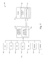
- FIGURE 1 is a block diagram of a position validation system 100 according to embodiments described herein.
- FIGURE 1 will be used to introduce the components of the position validation system 100. A detailed explanation and example embodiments will then be discussed with respect to FIGURES 2-6 .
- the position validation system 100 includes a position validation computer 102 and an ECDIS 104. It should be appreciated that in some implementations, the position validation computer 102 may be incorporated into the ECDIS 104 or vice versa. For clarity, the position validation computer 102 and ECDIS will be described as separate components that may communicate directly or via a network (not shown here).
- the position validation computer 102 may store and execute a position validation application 106 that is operative to validate the position of the ship per the embodiments disclosed herein. Further components of the position validation computer 102 will be described in greater detail below with respect to FIGURE 7 .
- the position validation computer 102 receives position data from any type and number of positioning systems 107.
- the ship's position is plotted within the surrounding environment corresponding to at least two positioning systems 107, and the images are scaled, overlaid, and aligned to determine if an offset exists that exceeds a predetermined threshold. If the threshold offset is exceeded, then the position validation application provides a visual and/or audible notification 122 on or in conjunction with the electronic chart 120 of the ECDIS 104.
- the notification 122 may be provided from the ECDIS 104 or elsewhere, including from a separate component. Also, the nature and method of notification 122 may vary to reflect the level of urgency and the amount the threshold is exceeded.
- the position validation computer 102 may utilize position data from any type of positioning systems 107.
- positioning systems 107 include, but are not limited to, GPS 108, automatic identification system (AIS) 110, very high frequency (VHF) direction finder 112, shore-based cellular phone towers 114, inertial navigation system (INS) 116, radar 118, and sonar 119.
- the position validation computer 102 executing the position validation application 106 will utilize at least two positioning systems 107. Because the ECDIS 104 of many conventional ships utilize GPS 108 for determining the position of the ship and plotting that position accordingly on the electronic chart 120, this disclosure will describe the GPS 108 as the first positioning system 107 for which a second positioning system 107 will be used for position validation. It should be appreciated, however, that any two or more positioning systems 107 may be used by the position validation application 107 in validating the position of the ship. Each positioning system will be described further below.
- FIGURE 2 an example of an electronic chart 120 of an ECDIS 104 will be described.
- the electronic chart 120 shown and described here will be used in FIGURES 4-5B to illustrate an example of the validation process according to one embodiment.
- the electronic chart 120 shown in FIGURE 2 includes a number of environmental elements 202.
- an "environmental element” may include any type of object, land, vehicle, or feature, man-made or natural, that may be plotted on an electronic chart 120 and may be of interest to the captain or crew of a ship in the area.
- two types of environmental elements 202 are shown here, objects 204 and land 206.
- the objects 204 may include buoys, channel markers, or any other type of objects that may be of a navigational interest to the crew of the ship. Various types of symbols and identification patterns on those symbols are shown, but are not relevant to this discussion. It should be understood that conventional electronic charts 120 may be very complex, depicting large quantities of information using various and often numerous symbols, shapes, colors, patterns, and graphics.
- the objects 204 have been simplified in this example in both type and quantity for clarity purposes.
- the land 206 may include rocks, soil, sand, reef, or any type of land that is exposed or submerged at a depth that may be a hazard to the ship.
- the electronic chart 120 plots a ship indicator 210 at the position of the ship according to current or recent GPS data.
- GPS is typically used by the ECDIS 104 to determine and plot the position of the ship indicator 210 on the electronic chart 120, although any positioning system 107 may be used.
- the accuracy of the position of the ship indicator 210 is paramount to the captain and crew of the ship. As the ship navigates close to shore or through potentially hazardous areas such as these, the crew's attention may be diverted while maneuvering the ship or communicating with other traffic. However, it is during times such as these that validating the ship's GPS position should be a high priority due to the impact of any error. Because manual confirmation of the GPS position is time consuming, it may not be possible or practical, leading to an increased risk for error and for corresponding mishap.
- FIGURE 3 shows an example of a radar image 300 captured from the ship of FIGURE 2 .
- Radar 118 is a positioning system 107 that may be used by the position validation application 106 to validate the position of the ship.
- Radar 118 is a well-known system in which a ship-based radar antenna or transmitter transmits radio waves and receives and interprets the energy reflected back by surrounding objects to create the radar image 300 that visually represents the surrounding environment.
- the radar image 300 shows a number of environmental element reflections 302.
- the environmental element reflections 302 correspond to the environmental elements 202 shown and described above with respect to FIGURE 2 .
- the environmental element reflections 302 include object reflections 304 and land reflections 306 corresponding to the objects 204 and land 206.
- the center of the radar image 300 represents the ship radar indicator 310, which is the location of the radar transmitter, and consequently, the location of the ship. For clarity purposes, the location of the ship has been encircled with a broken line.
- the position validation application 106 of this embodiment utilizes the radar image 300.
- the position validation application 106 overlays the radar image 300 on the electronic chart 120 to create an image overlay 400.
- the radar image 300 and the electronic chart 120 are both visible, but not yet aligned.
- the environmental element reflections 302 must be substantially aligned with the corresponding environmental elements 202.
- the land reflections 306 represent the leading edge of the land 206, but do not yet align with the representations of the land 206.
- the dots that represent the object reflections 304 do not yet align with the objects 204 represented on the electronic chart 120.
- the ship indicator 210 does not align with the ship radar indicator 310.
- the position validation application 106 aligns the environmental element reflections 302 with the corresponding environmental elements 202 in order to properly align the images, as seen in FIGURE 5A .
- the image overlay 400 of FIGURE 5A shows the result of the alignment of the radar image 300 with the electronic chart 120 such that the environmental element reflections 302 align with the corresponding environmental elements 202.
- the object reflections 304 substantially align with the objects 204
- the land reflections 306 substantially align with the edge of the land 206 where the land and water meet.
- the position validation application may analyze the electronic chart 120 image and the radar image 300 to detect edges, colors, symbols, and like features using known technology.
- the position validation application 106 may compare the indicated positions of the ship to determine if any offset exists. For example, looking at FIGURE 5A , the broken circle highlights the ship indicator 210 that represents the position of the ship according to GPS 108, as well as the ship radar indicator 310 that represents the position of the ship according to radar 118. Because the ship indicator 210 and ship radar indicator 310 are located at substantially the same geographic location, the position validation application 106 may conclude that the ship's position as indicated by the ship indicator 210 is correct and take no further immediate action.
- FIGURE 5B illustrates the image overlay 400 of the radar image 300 and electronic chart 120 that, when properly aligned such that the environmental element reflections 302 align with the corresponding environmental elements 202, illustrates an offset 502 between the ship indicator 210 and the ship radar indicator 310.
- the position validation application 106 determines what the offset 502 in any predetermined format, including but not limited to a specific distance directly between the two positions, an x-axis or y-axis component of the separation between the two positions, or a depth discrepancy if operating in a three-dimensional environment such as with a submarine. After determining the offset 502, the position validation application 106 compares the offset 502 to a predetermined threshold offset in order to determine whether or not a notification 122 is to be provided.
- the position validation application 106 provides a notification 122 to the captain or crew.
- the notification may be audible, visual, tactile (vibrations), or a combination thereof.
- the ship indicator 210 on the electronic chart 120 may turn red and flash, while text simultaneously appears at a location on the electronic chart 120 that indicates a potential position discrepancy.
- the position validation application 106 may also, automatically or in response to a manual request, provide the image overlay 400 to show the radar image 300 and offset 502 to the captain. The captain may then determine a course of action, which may include further validation with a third positioning system 107. If a notification 122 is not acknowledged within a specified period of time, its urgency may increase both visually and audibly.
- the threshold offset may be set or predetermined according to standard minimums used by a particular regulatory agency, industry, company, or crew to be used uniformly in all situations and environments. According to an alternative embodiment, the threshold offset may change or be customized according to any criteria, including but not limited to, the particular geographic area, vehicle operating parameters, time of day, weather conditions, or mission. For example, the threshold offset may decrease as the speed of the ship increases in order to provide the crew with more time to slow or alter course should even a minor positioning error be determined. Similar decreases in the threshold offset may be desired if the visibility decreases due to darkness or weather conditions. In geographic areas with many potential hazards in which accurate positioning is paramount, the threshold offset may be minimized to ensure that any positioning errors are discovered and corrected early. Similarly, in open unrestricted areas with no nearby hazards, the threshold may be increased, for example, to decrease the likelihood of unnecessary notifications 122.
- any other positioning system 107 may be used by the position validation application 106.
- other positioning systems 107 may be utilized as the first positioning system used to plot the ship indicator 210 on the electronic chart 120, rather than GPS 108.
- Various examples will now be described to illustrate the use of the positioning systems 107 shown in FIGURE 1 .
- AIS 110 technology may be used to plot the position of a nearby ship ("traffic").
- traffic AIS transmissions from the traffic are received at the ship and converted to ASCII and parsed.
- the traffic identification, GPS position, course over ground, true bearing, and other information may be included in the AIS transmissions.
- the converted data may be used to plot the position of the traffic on the electronic chart 120 per known techniques.
- Radar 118 may then be used as a second positioning system for validation purposes.
- a radar image 300 is created and overlaid on the electronic chart 120 as described above with respect to FIGURES 3-5B .
- the position validation application 106 aligns the radar reflection of the traffic with the plotted representation of the traffic on the electronic chart.
- the position validation application 106 may then determine the offset 502 between the ship radar indicator 310 and the ship indicator 210 (determined using GPS 108 or other positioning system 107) and determine if a threshold offset has been exceeded.
- AIS broadcasts from numerous traffic ships and fixed objects may be used to plot corresponding representations on the electronic chart 120, which provide for numerous environmental elements 202 against which corresponding environmental element reflections 302 may be aligned prior to determining the offset 502.
- AIS information may be used to look up detailed information regarding the broadcasting vessel.
- a graphic representation of the vessel (vector or pixel) may be constructed and plotted at the determined location on the electronic chart 120.
- the radar reflection of the vessel may be used to compare the radar image size of the vessel with the graphic representation based on AIS information to confirm match and alignment of the radar and electronic chart representations.
- VHF transmissions may be used for direction finding, such as with VHF omnidirectional radio range (VOR) systems.
- VOR VHF omnidirectional radio range
- the position validation application 106 may determine the position of the ship. This location may be superimposed onto the electronic chart 120 for determination of the offset 502 with respect to the ship indicator 210 positioned according to a location determination made using GPS 108 or other positioning system 107.
- the position validation application 106 may utilize triangulation techniques and signals from shore-based cellular phone towers 114 to determine the position of the ship. Data from an INS 116 may also be used for position determination and validation based on dead reckoning and associated navigational tools coupled with a prior validated ship position.
- any position determination techniques and technology may be used to determine the position of the ship using at least two different positioning systems 107. These positions may then be separately plotted, scaled to match one another, overlaid, aligned, and compared to determine the offset 502. The offset is compared to a threshold offset, which if exceeded, results in a notification 122 provided to the captain or crew.
- the notification may be visual, audible, tactile, or a combination thereof.
- a notification 122 that the validation process has been performed and a threshold offset has not been exceeded may be provided to ensure the captain or crew that validation is ongoing and the indicated ship's position is accurate.
- this validation process occurs automatically in the background, providing and validating an accurate representation of the position of the ship on the electronic chart 120, with notifications 122 provided if a threshold offset is exceeded. Because the overlay of the radar image 300 and electronic chart 120 occurs in the background without being displayed on the ECDIS 104, clutter on the electronic chart is reduced. If a threshold offset is exceeded, or if desired at any time by the captain or crew, the overlay of the images may be visualized on the ECDIS 104.
- a traffic ship's position may be validated using AIS 110 information from the traffic, as well as radar 118 from the ship doing the validating (primary ship).
- the difference from this scenario and the example described above in which the position of the primary ship was being validated using AIS 110 and radar 118 information is that during alignment, the position validation application 106 aligns the radar image 300 and electronic chart 120 using the primary ship's position, as well as those of other environmental elements 202.
- the offset 502 is then calculated with respect to the traffic ship to determine if the positions of the traffic ship with respect to the AIS information and the radar reflection are accurate.
- the position validation application 106 may align images according to the "best fit" of the majority of environmental elements 202 and corresponding environmental element reflections 302, and provide notifications 122 regarding any offsets 502 that exceed an applicable threshold. In this manner, the captain or crew may be provided with up-to-date information regarding any position anomalies corresponding to the ship itself, or any surrounding elements.
- FIGURE 6 additional details will be provided regarding embodiments presented herein for providing an automated validation of vehicle positioning.
- the logical operations described herein are implemented (1) as a sequence of computer implemented acts or program modules running on a computing system and/or (2) as interconnected machine logic circuits or circuit modules within the computing system. The implementation is a matter of choice dependent on the performance and other operating parameters of the computing system. Accordingly, the logical operations described herein are referred to variously as operations, structural devices, acts, or modules. These operations, structural devices, acts, and modules may be implemented in software, in firmware, hardware, in special purpose digital logic, and any combination thereof. It should also be appreciated that more or fewer operations may be performed than shown in the figures and described herein. These operations may also be performed in parallel, or in a different order than those described herein.
- FIGURE 6 shows a routine 600 for validating vehicle positioning and providing appropriate error notification.
- the routine 600 may be performed by the position validation application 106, including or in combination with the ECDIS 104.
- the routine 600 begins at operation 602, where the position validation application 106 determines a first position of the ship according to a first positioning system 107.
- this first positioning system may include GPS 108.
- the first position determined at operation 602 may be the position of the traffic ship or other object or environmental element 202.
- the routine 600 continues to operation 604, where the position validation application 106 provides the first position of the ship and any appropriate environmental elements 202 on a first image. From the examples provided above, this operation may include providing the ship indicator 210 on the electronic chart 120, which includes the representations of the environmental elements 202.
- the routine 600 continues to operation 606, where the position validation application 106 determines a second position of the ship according to a second positioning system 107.
- the second position of the ship may be at the ship radar indicator 310 located at the center of the radar image 300 created via radar 118. When validating the position of an element surrounding the ship, this second position may be the position of an environmental element reflection 302 or traffic reflection with respect to the position of the ship at the center of the radar image 300.
- routine 600 continues to operation 608, where the position validation application 106 provides the second position of the ship and any appropriate environmental elements 202 on a second image. Continuing with the examples provided above, this operation may include providing the radar image 300 having the ship radar indicator 310 and appropriate environmental element reflections 302. The routine 600 continues to operation 610, where the position validation application 106 scales and aligns the images, such as scaling and aligning the radar image 300 over the electronic chart 120 with the representations of the environmental elements 202 aligning with the environmental element reflections 302.
- the offset 502 with respect to the positions of the ship or with respect to an applicable environmental element 202 is determined, and at operation 614, the position validation application 106 determines if the offset 502 exceeds a threshold offset. If the threshold offset is exceeded, then the routine 600 proceeds to operation 616, where a notification 122 is provided via the ECDIS 104 or other desired means. The routine 600 then returns to operation 602 and proceeds as described above. It should be appreciated that the routine 600, or the return to operation 602 and repeat of the routine 600, may be initiated by any predetermined or customized trigger, including but not limited to, a programmed time interval, a location of the ship, operating parameter of the ship, manual initiation, or a combination thereof. Returning to operation 614, if the position validation application 106 determines that the offset 502 does not exceed a threshold offset, then the routine returns to operation 602 and proceeds as described above.
- FIGURE 7 shows an illustrative position validation computer 102 capable of executing the software elements described herein for providing validation of a vehicle position.
- the position validation computer 102 may be embodied in single computing device or in a combination of one or more processing units, storage units, and/or other computing devices. As described above, the position validation computer 102 may include the ECDIS 104, or may operate in combination with the ECDIS 104.
- the position validation computer 102 includes one or more central processing units 702 ("CPUs"), a system memory 704, including a random access memory 706 (“RAM”) and a read-only memory 708 (“ROM”), and a system bus 710 that couples the memory to the CPUs 702.
- CPUs central processing units
- RAM random access memory
- ROM read-only memory
- the CPUs 702 may be standard programmable processors that perform arithmetic and logical operations necessary for the operation of the position validation computer 102.
- the CPUs 702 may perform the necessary operations by transitioning from one discrete, physical state to the next through the manipulation of switching elements that differentiate between and change these states.
- Switching elements may generally include electronic circuits that maintain one of two binary states, such as flip-flops, and electronic circuits that provide an output state based on the logical combination of the states of one or more other switching elements, such as logic gates. These basic switching elements may be combined to create more complex logic circuits, including registers, adders-subtractors, arithmetic logic units, floating-point units, and the like.
- the position validation computer 102 also includes a mass storage device 712.
- the mass storage device 712 may be connected to the CPUs 702 through a mass storage controller (not shown) further connected to the bus 710.
- the mass storage device 712 and its associated computer-readable media provide non-volatile, non-transitory storage for the position validation computer 102.
- the mass storage device 712 may store an operating system 718, as well as specific application modules or other program modules, such as the position validation application 106, described above.
- the mass storage device 712 may also store data collected or utilized by the various systems and modules, such as the electronic chart 120 and notifications 122 described above.
- the position validation computer 102 may store programs and data on the mass storage device 712 by transforming the physical state of the mass storage device to reflect the information being stored.
- the specific transformation of physical state may depend on various factors, in different implementations of this disclosure. Examples of such factors may include, but are not limited to, the technology used to implement the mass storage device 712, whether the mass storage device is characterized as primary or secondary storage, and the like.
- the position validation computer 102 may store information to the mass storage device 712 by issuing instructions through the storage controller to alter the magnetic characteristics of a particular location within a magnetic disk drive device, the reflective or refractive characteristics of a particular location in an optical storage device, or the electrical characteristics of a particular capacitor, transistor, or other discrete element in a solid-state storage device.
- the position validation computer 102 may further read information from the mass storage device 712 by detecting the physical states or characteristics of one or more particular locations within the mass storage device.
- Computer-readable media can be any available computer media that can be accessed by the position validation computer 102.
- Computer-readable media includes communication media, such as signals, and computer-readable storage media.
- Computer-readable storage media includes volatile and non-volatile, removable and non-removable media implemented in any method or technology for the storage of information, such as computer-readable instructions, data structures, program modules, or other data.
- computer-readable storage media includes, but is not limited to, RAM, ROM, EPROM, EEPROM, flash memory or other solid state memory technology, CD-ROM, digital versatile disks ("DVD"), HD-DVD, BLU-RAY, or other optical storage, magnetic cassettes, magnetic tape, magnetic disk storage or other magnetic storage devices, or any other medium which can be used to store the desired information in a non-transitory fashion and which can be accessed by the position validation computer 102.
- the position validation computer 102 may have access to computer-readable storage media storing computer-executable instructions that, when executed by the computer, perform the routine 600 for providing an automated cross-check of vehicle positioning and corresponding error notification, as described above in regard to FIGURE 6 .
- the position validation computer 102 may operate in a networked environment using logical connections to remote computers through a network, such as the network 701.
- the position validation computer 102 may connect to the network 701 through a network interface unit 806 connected to the bus 710. It should be appreciated that the network interface unit 806 may also be utilized to connect to other types of networks and remote computer systems.
- the position validation computer 102 may also include an input/output controller 716 for providing output to a display device, such as an ECDIS 104, computer monitor, a printer, or other type of output device.
- the input/output controller 716 may further receive input from devices, such as a keyboard, mouse, electronic stylus, touch screen, and the like. It will be further appreciated that the position validation computer 102 may not include all of the elements shown in FIGURE 7 , may include other elements that are not explicitly shown in FIGURE 7 , or may utilize an architecture completely different than that shown in FIGURE 7 .
Abstract
Description
- Ships and other vehicles often utilize various types of positioning systems and technologies to safely navigate between locations. For example, ship crews may employ an electronic chart, such as an electronic chart display and information system (ECDIS), and global positioning system (GPS) to provide a dynamic, real-time visualization of the geographical features of the surrounding environment and the precise position of the ship within that environment. As the ship moves through an area, the ECDIS provides a visualization of the ship's location with respect to the fixed objects, land, and other features around the ship that could present a navigational hazard.
- However, limitations of GPS technology introduce errors that may result in the inaccurate positioning of the ship on the ECDIS. In other words, the displayed position of the ship on the electronic chart utilized by the crew may not be accurate due to GPS errors. If relied upon as the sole means of navigation, an inaccurate representation of the ship's position due to a GPS error could result in the ship running aground or coming into contact with a fixed object. To account for the potential for errors, a crew member must manually confirm the ship's positioning via another navigational tool in order to ensure that the position of the ship on the electronic chart is accurate. Doing so takes time and attention away from other duties. Inattentive seamanship due to overly optimistic reliance on technology could result in an accident, close call, or navigational error as the ship may be positioned at a location that is substantially different from the position indicated on the electronic chart.
- It is with respect to these considerations and others that the disclosure made herein is presented.
- It should be appreciated that this Summary is provided to introduce a selection of concepts in a simplified form that are further described below in the Detailed Description. This Summary is not intended to be used to limit the scope of the claimed subject matter.
- Methods and computer-readable media are described herein for providing an automated validation of vehicle or other element positioning and corresponding error notification. According to embodiments presented herein, a first position of a vehicle may be determined using a first positioning system. A second position of the vehicle may be determined using a second positioning system. A position validation computer may determine an offset between the first and second positions, and if the offset exceeds a threshold offset, may provide a notification to indicate a potential error in the position of the vehicle.
- According to another aspect, a computer-implemented method for validating a position of a vehicle may include determining a first position of an element with respect to a first position of the vehicle using a first positioning system. Representations of the element and of the vehicle may be provided at their respective positions on a first image. A second position of the element with respect to a second position of the vehicle may be determined using a second positioning system. Representations of the element and of the vehicle may be provided at their respective second positions on a second image. The two images may be aligned such that the first position of the element aligns with the second position of the element. An offset between the first and second positions of the vehicle may be determined, and if the offset exceeds a threshold offset, a notification may be provided.
- According to yet another aspect, a first position of a ship may be determined using a GPS and plotted on an electronic chart. A second position of the ship may be determined using a second positioning system. An offset between the first position and the second position may be determined. If the offset exceeds a threshold offset, then a notification may be provided to indicate a potential error in the position of the ship.
- The features, functions, and advantages discussed herein can be achieved independently in various embodiments of the present disclosure or may be combined in yet other embodiments, further details of which can be seen with reference to the following description and drawings.
-
-
FIGURE 1 is a block diagram of a position validation system according to various embodiments presented herein; -
FIGURE 2 is a top view of an electronic chart showing an illustrative representation of the position of a ship according to a GPS or other positioning system, as well as the positions of surrounding land and other objects, according to various embodiments presented herein; -
FIGURE 3 is a top view of an illustrative radar image originating from the ship ofFIGURE 2 , showing radar reflections of the land and other objects surrounding the ship, according to various embodiments presented herein; -
FIGURE 4 is a top view of the electronic chart ofFIGURE 2 with the radar image ofFIGURE 3 overlaid but unaligned, according to various embodiments presented herein; -
FIGURE 5A is a top view of the radar image ofFIGURE 3 overlaid and aligned with the electronic chart ofFIGURE 2 , illustrating confirmation of ship position according to various embodiments presented herein; -
FIGURE 5B is a top view of the radar image ofFIGURE 3 overlaid and aligned with the electronic chart ofFIGURE 2 , illustrating an offset in ship position, indicating an error according to various embodiments presented herein; -
FIGURE 6 is a flow diagram illustrating a method for validating vehicle position, in accordance with the embodiments presented herein; and -
FIGURE 7 is a block diagram showing an illustrative computer hardware and software architecture for a computing system capable of implementing aspects of the embodiments presented herein. - The following detailed description is directed to methods, computer-readable storage media, and other suitable technologies for providing an automated validation of vehicle positioning and corresponding error notification. It should be appreciated that for clarity purposes, concepts disclosed herein will be described in the context of a ship, and the confirmation of the geographic location or position of the ship at any given time. Although the concepts will be described in the context of a ship, the concepts and technologies described herein are applicable to any vehicle, land, sea, or air. Consequently, a "vehicle" as described herein and as recited in the accompanying claims, may include, but is not limited to, a ship, boat, submersible, aircraft, dirigible, land-based vehicle or craft, spacecraft, or any transportation apparatus that is capable of utilizing any number of positioning systems to establish its geographic location.
- As discussed briefly above, ship crews often utilize an electronic chart for navigational purposes. The electronic chart typically plots a representation of the ship's position according to GPS data, along with surrounding environmental features such as the location of nearby land, fixed objects such as buoys, underwater hazards such as reefs or shallow areas, as well as nearby ships and other moving objects whose positions are known. Typical electronic charts, just like conventional paper-based charts, are very accurate, providing the precise geographic location of all potential hazards. However, when operating in restricted waters such as coastal areas, ports, harbors, fjords, bays, deltas, and rivers, a ship's captain relies on the accurate positioning of the ship on the electronic chart for safe navigation.
- When working properly, GPS is very accurate. Ships and other vehicles utilize GPS technology to determine the location of the ship within a very small margin of error. However, equipment failures in a GPS satellite and/or a shipboard receiver, incorrect calibrations in the GPS satellite, GPS receiving equipment, or the ECDIS, among other reasons, may result in the incorrect positioning of the ship by an offset distance that can be significant. If unnoticed, such offsets may lead the captain or crew to believe that the ship is in a different location than it actually is, and could cause them to inadvertently run the ship aground or into submerged hazards.
- According to the concepts and technologies described herein, a position validation computer electronically compares a position of the ship obtained via GPS or other positioning system, to a ship position obtained by an independent positioning system. If the two ship positions are offset by a threshold distance, a visual and/or audible notification is provided to the captain or crew. As a result, the crew is able to devote time to other duties without concern for errors in the plotted position of the ship or for performing manual validation.
- In the following detailed description, references are made to the accompanying drawings that form a part hereof and that show, by way of illustration, specific embodiments, or examples. In referring to the drawings, like numerals represent like elements throughout the several figures.
FIGURE 1 is a block diagram of aposition validation system 100 according to embodiments described herein.FIGURE 1 will be used to introduce the components of theposition validation system 100. A detailed explanation and example embodiments will then be discussed with respect toFIGURES 2-6 . - According to various embodiments, the
position validation system 100 includes aposition validation computer 102 and an ECDIS 104. It should be appreciated that in some implementations, theposition validation computer 102 may be incorporated into the ECDIS 104 or vice versa. For clarity, theposition validation computer 102 and ECDIS will be described as separate components that may communicate directly or via a network (not shown here). - The
position validation computer 102 may store and execute aposition validation application 106 that is operative to validate the position of the ship per the embodiments disclosed herein. Further components of theposition validation computer 102 will be described in greater detail below with respect toFIGURE 7 . According to various embodiments, theposition validation computer 102 receives position data from any type and number ofpositioning systems 107. The ship's position is plotted within the surrounding environment corresponding to at least twopositioning systems 107, and the images are scaled, overlaid, and aligned to determine if an offset exists that exceeds a predetermined threshold. If the threshold offset is exceeded, then the position validation application provides a visual and/oraudible notification 122 on or in conjunction with theelectronic chart 120 of theECDIS 104. It should be appreciated that thenotification 122 may be provided from theECDIS 104 or elsewhere, including from a separate component. Also, the nature and method ofnotification 122 may vary to reflect the level of urgency and the amount the threshold is exceeded. - The
position validation computer 102 may utilize position data from any type ofpositioning systems 107. Examples ofpositioning systems 107 include, but are not limited to,GPS 108, automatic identification system (AIS) 110, very high frequency (VHF)direction finder 112, shore-based cellular phone towers 114, inertial navigation system (INS) 116,radar 118, andsonar 119. According to various embodiments, theposition validation computer 102 executing theposition validation application 106 will utilize at least twopositioning systems 107. Because theECDIS 104 of many conventional ships utilizeGPS 108 for determining the position of the ship and plotting that position accordingly on theelectronic chart 120, this disclosure will describe theGPS 108 as thefirst positioning system 107 for which asecond positioning system 107 will be used for position validation. It should be appreciated, however, that any two ormore positioning systems 107 may be used by theposition validation application 107 in validating the position of the ship. Each positioning system will be described further below. - Turning now to
FIGURE 2 , an example of anelectronic chart 120 of anECDIS 104 will be described. Theelectronic chart 120 shown and described here will be used inFIGURES 4-5B to illustrate an example of the validation process according to one embodiment. Theelectronic chart 120 shown inFIGURE 2 includes a number ofenvironmental elements 202. As used herein, an "environmental element" may include any type of object, land, vehicle, or feature, man-made or natural, that may be plotted on anelectronic chart 120 and may be of interest to the captain or crew of a ship in the area. For clarity purposes, two types ofenvironmental elements 202 are shown here, objects 204 andland 206. - The
objects 204 may include buoys, channel markers, or any other type of objects that may be of a navigational interest to the crew of the ship. Various types of symbols and identification patterns on those symbols are shown, but are not relevant to this discussion. It should be understood that conventionalelectronic charts 120 may be very complex, depicting large quantities of information using various and often numerous symbols, shapes, colors, patterns, and graphics. Theobjects 204 have been simplified in this example in both type and quantity for clarity purposes. Theland 206 may include rocks, soil, sand, reef, or any type of land that is exposed or submerged at a depth that may be a hazard to the ship. - The
electronic chart 120 plots aship indicator 210 at the position of the ship according to current or recent GPS data. As previously discussed, GPS is typically used by theECDIS 104 to determine and plot the position of theship indicator 210 on theelectronic chart 120, although anypositioning system 107 may be used. As seen in this example, due to the proximity of the ship with theland 206 andnumerous objects 204, the accuracy of the position of theship indicator 210 is paramount to the captain and crew of the ship. As the ship navigates close to shore or through potentially hazardous areas such as these, the crew's attention may be diverted while maneuvering the ship or communicating with other traffic. However, it is during times such as these that validating the ship's GPS position should be a high priority due to the impact of any error. Because manual confirmation of the GPS position is time consuming, it may not be possible or practical, leading to an increased risk for error and for corresponding mishap. -
FIGURE 3 shows an example of aradar image 300 captured from the ship ofFIGURE 2 .Radar 118 is apositioning system 107 that may be used by theposition validation application 106 to validate the position of the ship.Radar 118 is a well-known system in which a ship-based radar antenna or transmitter transmits radio waves and receives and interprets the energy reflected back by surrounding objects to create theradar image 300 that visually represents the surrounding environment. Theradar image 300 shows a number ofenvironmental element reflections 302. In this example, theenvironmental element reflections 302 correspond to theenvironmental elements 202 shown and described above with respect toFIGURE 2 . Theenvironmental element reflections 302 includeobject reflections 304 andland reflections 306 corresponding to theobjects 204 andland 206. The center of theradar image 300 represents theship radar indicator 310, which is the location of the radar transmitter, and consequently, the location of the ship. For clarity purposes, the location of the ship has been encircled with a broken line. - In order to validate the GPS position of the ship as represented on the
electronic chart 120 by theship indicator 210, theposition validation application 106 of this embodiment utilizes theradar image 300. Looking atFIGURE 4 , after properly scaling theradar image 300 to match the scale of theelectronic chart 120, theposition validation application 106 overlays theradar image 300 on theelectronic chart 120 to create animage overlay 400. In theimage overlay 400, theradar image 300 and theelectronic chart 120 are both visible, but not yet aligned. In order to validate the position of the ship, theenvironmental element reflections 302 must be substantially aligned with the correspondingenvironmental elements 202. As seen here, theland reflections 306 represent the leading edge of theland 206, but do not yet align with the representations of theland 206. Similarly, the dots that represent theobject reflections 304 do not yet align with theobjects 204 represented on theelectronic chart 120. For at least the reason that the images are not yet aligned, theship indicator 210 does not align with theship radar indicator 310. - After creating the
image overlay 400, theposition validation application 106 aligns theenvironmental element reflections 302 with the correspondingenvironmental elements 202 in order to properly align the images, as seen inFIGURE 5A . Theimage overlay 400 ofFIGURE 5A shows the result of the alignment of theradar image 300 with theelectronic chart 120 such that theenvironmental element reflections 302 align with the correspondingenvironmental elements 202. As seen, theobject reflections 304 substantially align with theobjects 204, while theland reflections 306 substantially align with the edge of theland 206 where the land and water meet. In aligning the images to create theimage overlay 400, the position validation application may analyze theelectronic chart 120 image and theradar image 300 to detect edges, colors, symbols, and like features using known technology. - Once the images are properly aligned, the
position validation application 106 may compare the indicated positions of the ship to determine if any offset exists. For example, looking atFIGURE 5A , the broken circle highlights theship indicator 210 that represents the position of the ship according toGPS 108, as well as theship radar indicator 310 that represents the position of the ship according toradar 118. Because theship indicator 210 andship radar indicator 310 are located at substantially the same geographic location, theposition validation application 106 may conclude that the ship's position as indicated by theship indicator 210 is correct and take no further immediate action. - In contrast,
FIGURE 5B illustrates theimage overlay 400 of theradar image 300 andelectronic chart 120 that, when properly aligned such that theenvironmental element reflections 302 align with the correspondingenvironmental elements 202, illustrates an offset 502 between theship indicator 210 and theship radar indicator 310. Theposition validation application 106 determines what the offset 502 in any predetermined format, including but not limited to a specific distance directly between the two positions, an x-axis or y-axis component of the separation between the two positions, or a depth discrepancy if operating in a three-dimensional environment such as with a submarine. After determining the offset 502, theposition validation application 106 compares the offset 502 to a predetermined threshold offset in order to determine whether or not anotification 122 is to be provided. - For example, if the offset 502 of
FIGURE 5B is approximately 500 meters and the threshold offset for that particular geographic area or operating condition is 100 meters, then theposition validation application 106 provides anotification 122 to the captain or crew. The notification may be audible, visual, tactile (vibrations), or a combination thereof. As an example, theship indicator 210 on theelectronic chart 120 may turn red and flash, while text simultaneously appears at a location on theelectronic chart 120 that indicates a potential position discrepancy. Theposition validation application 106 may also, automatically or in response to a manual request, provide theimage overlay 400 to show theradar image 300 and offset 502 to the captain. The captain may then determine a course of action, which may include further validation with athird positioning system 107. If anotification 122 is not acknowledged within a specified period of time, its urgency may increase both visually and audibly. - The threshold offset may be set or predetermined according to standard minimums used by a particular regulatory agency, industry, company, or crew to be used uniformly in all situations and environments. According to an alternative embodiment, the threshold offset may change or be customized according to any criteria, including but not limited to, the particular geographic area, vehicle operating parameters, time of day, weather conditions, or mission. For example, the threshold offset may decrease as the speed of the ship increases in order to provide the crew with more time to slow or alter course should even a minor positioning error be determined. Similar decreases in the threshold offset may be desired if the visibility decreases due to darkness or weather conditions. In geographic areas with many potential hazards in which accurate positioning is paramount, the threshold offset may be minimized to ensure that any positioning errors are discovered and corrected early. Similarly, in open unrestricted areas with no nearby hazards, the threshold may be increased, for example, to decrease the likelihood of
unnecessary notifications 122. - When
radar 118 is not available, anyother positioning system 107 may be used by theposition validation application 106. Similarly,other positioning systems 107 may be utilized as the first positioning system used to plot theship indicator 210 on theelectronic chart 120, rather thanGPS 108. Various examples will now be described to illustrate the use of thepositioning systems 107 shown inFIGURE 1 . - According to one example,
AIS 110 technology may be used to plot the position of a nearby ship ("traffic"). In doing so, AIS transmissions from the traffic are received at the ship and converted to ASCII and parsed. The traffic identification, GPS position, course over ground, true bearing, and other information may be included in the AIS transmissions. The converted data may be used to plot the position of the traffic on theelectronic chart 120 per known techniques. -
Radar 118 may then be used as a second positioning system for validation purposes. Aradar image 300 is created and overlaid on theelectronic chart 120 as described above with respect toFIGURES 3-5B . In aligning theradar image 300 with theelectronic chart 120, theposition validation application 106 aligns the radar reflection of the traffic with the plotted representation of the traffic on the electronic chart. As described above with respect toFIGURE 5B , theposition validation application 106 may then determine the offset 502 between theship radar indicator 310 and the ship indicator 210 (determined usingGPS 108 or other positioning system 107) and determine if a threshold offset has been exceeded. It should be appreciated that AIS broadcasts from numerous traffic ships and fixed objects may be used to plot corresponding representations on theelectronic chart 120, which provide for numerousenvironmental elements 202 against which correspondingenvironmental element reflections 302 may be aligned prior to determining the offset 502. It should also be appreciated that AIS information may be used to look up detailed information regarding the broadcasting vessel. In doing so, a graphic representation of the vessel (vector or pixel) may be constructed and plotted at the determined location on theelectronic chart 120. The radar reflection of the vessel may be used to compare the radar image size of the vessel with the graphic representation based on AIS information to confirm match and alignment of the radar and electronic chart representations. - Another
positioning system 107 includes aVHF direction finder 112. VHF transmissions may be used for direction finding, such as with VHF omnidirectional radio range (VOR) systems. Using VOR technologies, theposition validation application 106 may determine the position of the ship. This location may be superimposed onto theelectronic chart 120 for determination of the offset 502 with respect to theship indicator 210 positioned according to a location determination made usingGPS 108 orother positioning system 107. Similarly, theposition validation application 106 may utilize triangulation techniques and signals from shore-based cellular phone towers 114 to determine the position of the ship. Data from anINS 116 may also be used for position determination and validation based on dead reckoning and associated navigational tools coupled with a prior validated ship position. - It should be understood from the examples provided herein that any position determination techniques and technology may be used to determine the position of the ship using at least two
different positioning systems 107. These positions may then be separately plotted, scaled to match one another, overlaid, aligned, and compared to determine the offset 502. The offset is compared to a threshold offset, which if exceeded, results in anotification 122 provided to the captain or crew. The notification may be visual, audible, tactile, or a combination thereof. Additionally, according to one embodiment, anotification 122 that the validation process has been performed and a threshold offset has not been exceeded may be provided to ensure the captain or crew that validation is ongoing and the indicated ship's position is accurate. - According to various embodiments, this validation process occurs automatically in the background, providing and validating an accurate representation of the position of the ship on the
electronic chart 120, withnotifications 122 provided if a threshold offset is exceeded. Because the overlay of theradar image 300 andelectronic chart 120 occurs in the background without being displayed on theECDIS 104, clutter on the electronic chart is reduced. If a threshold offset is exceeded, or if desired at any time by the captain or crew, the overlay of the images may be visualized on theECDIS 104. - The concepts described herein may not only be used to validate the position of a ship, but also to validate the position of any object within the environment surround the ship. For example, a traffic ship's position may be validated using
AIS 110 information from the traffic, as well asradar 118 from the ship doing the validating (primary ship). The difference from this scenario and the example described above in which the position of the primary ship was being validated usingAIS 110 andradar 118 information is that during alignment, theposition validation application 106 aligns theradar image 300 andelectronic chart 120 using the primary ship's position, as well as those of otherenvironmental elements 202. The offset 502 is then calculated with respect to the traffic ship to determine if the positions of the traffic ship with respect to the AIS information and the radar reflection are accurate. Essentially, according to various embodiments, theposition validation application 106 may align images according to the "best fit" of the majority ofenvironmental elements 202 and correspondingenvironmental element reflections 302, and providenotifications 122 regarding anyoffsets 502 that exceed an applicable threshold. In this manner, the captain or crew may be provided with up-to-date information regarding any position anomalies corresponding to the ship itself, or any surrounding elements. - Referring now to
FIGURE 6 , additional details will be provided regarding embodiments presented herein for providing an automated validation of vehicle positioning. It should be appreciated that the logical operations described herein are implemented (1) as a sequence of computer implemented acts or program modules running on a computing system and/or (2) as interconnected machine logic circuits or circuit modules within the computing system. The implementation is a matter of choice dependent on the performance and other operating parameters of the computing system. Accordingly, the logical operations described herein are referred to variously as operations, structural devices, acts, or modules. These operations, structural devices, acts, and modules may be implemented in software, in firmware, hardware, in special purpose digital logic, and any combination thereof. It should also be appreciated that more or fewer operations may be performed than shown in the figures and described herein. These operations may also be performed in parallel, or in a different order than those described herein. -
FIGURE 6 shows a routine 600 for validating vehicle positioning and providing appropriate error notification. In some embodiments, the routine 600 may be performed by theposition validation application 106, including or in combination with theECDIS 104. The routine 600 begins atoperation 602, where theposition validation application 106 determines a first position of the ship according to afirst positioning system 107. According to examples described above, this first positioning system may includeGPS 108. As described above, according to alternative embodiments in which the position of an element surrounding the ship is to be validated, the first position determined atoperation 602 may be the position of the traffic ship or other object orenvironmental element 202. - From
operation 602, the routine 600 continues tooperation 604, where theposition validation application 106 provides the first position of the ship and any appropriateenvironmental elements 202 on a first image. From the examples provided above, this operation may include providing theship indicator 210 on theelectronic chart 120, which includes the representations of theenvironmental elements 202. The routine 600 continues tooperation 606, where theposition validation application 106 determines a second position of the ship according to asecond positioning system 107. As an example, the second position of the ship may be at theship radar indicator 310 located at the center of theradar image 300 created viaradar 118. When validating the position of an element surrounding the ship, this second position may be the position of anenvironmental element reflection 302 or traffic reflection with respect to the position of the ship at the center of theradar image 300. - From
operation 606, the routine 600 continues tooperation 608, where theposition validation application 106 provides the second position of the ship and any appropriateenvironmental elements 202 on a second image. Continuing with the examples provided above, this operation may include providing theradar image 300 having theship radar indicator 310 and appropriateenvironmental element reflections 302. The routine 600 continues tooperation 610, where theposition validation application 106 scales and aligns the images, such as scaling and aligning theradar image 300 over theelectronic chart 120 with the representations of theenvironmental elements 202 aligning with theenvironmental element reflections 302. - At
operation 612, the offset 502 with respect to the positions of the ship or with respect to an applicableenvironmental element 202 is determined, and atoperation 614, theposition validation application 106 determines if the offset 502 exceeds a threshold offset. If the threshold offset is exceeded, then the routine 600 proceeds tooperation 616, where anotification 122 is provided via theECDIS 104 or other desired means. The routine 600 then returns tooperation 602 and proceeds as described above. It should be appreciated that the routine 600, or the return tooperation 602 and repeat of the routine 600, may be initiated by any predetermined or customized trigger, including but not limited to, a programmed time interval, a location of the ship, operating parameter of the ship, manual initiation, or a combination thereof. Returning tooperation 614, if theposition validation application 106 determines that the offset 502 does not exceed a threshold offset, then the routine returns tooperation 602 and proceeds as described above. -
FIGURE 7 shows an illustrativeposition validation computer 102 capable of executing the software elements described herein for providing validation of a vehicle position. Theposition validation computer 102 may be embodied in single computing device or in a combination of one or more processing units, storage units, and/or other computing devices. As described above, theposition validation computer 102 may include theECDIS 104, or may operate in combination with theECDIS 104. Theposition validation computer 102 includes one or more central processing units 702 ("CPUs"), asystem memory 704, including a random access memory 706 ("RAM") and a read-only memory 708 ("ROM"), and asystem bus 710 that couples the memory to theCPUs 702. - The
CPUs 702 may be standard programmable processors that perform arithmetic and logical operations necessary for the operation of theposition validation computer 102. TheCPUs 702 may perform the necessary operations by transitioning from one discrete, physical state to the next through the manipulation of switching elements that differentiate between and change these states. Switching elements may generally include electronic circuits that maintain one of two binary states, such as flip-flops, and electronic circuits that provide an output state based on the logical combination of the states of one or more other switching elements, such as logic gates. These basic switching elements may be combined to create more complex logic circuits, including registers, adders-subtractors, arithmetic logic units, floating-point units, and the like. - The
position validation computer 102 also includes amass storage device 712. Themass storage device 712 may be connected to theCPUs 702 through a mass storage controller (not shown) further connected to thebus 710. Themass storage device 712 and its associated computer-readable media provide non-volatile, non-transitory storage for theposition validation computer 102. Themass storage device 712 may store anoperating system 718, as well as specific application modules or other program modules, such as theposition validation application 106, described above. Themass storage device 712 may also store data collected or utilized by the various systems and modules, such as theelectronic chart 120 andnotifications 122 described above. - The
position validation computer 102 may store programs and data on themass storage device 712 by transforming the physical state of the mass storage device to reflect the information being stored. The specific transformation of physical state may depend on various factors, in different implementations of this disclosure. Examples of such factors may include, but are not limited to, the technology used to implement themass storage device 712, whether the mass storage device is characterized as primary or secondary storage, and the like. For example, theposition validation computer 102 may store information to themass storage device 712 by issuing instructions through the storage controller to alter the magnetic characteristics of a particular location within a magnetic disk drive device, the reflective or refractive characteristics of a particular location in an optical storage device, or the electrical characteristics of a particular capacitor, transistor, or other discrete element in a solid-state storage device. Other transformations of physical media are possible without departing from the scope and spirit of the present description, with the foregoing examples provided only to facilitate this description. Theposition validation computer 102 may further read information from themass storage device 712 by detecting the physical states or characteristics of one or more particular locations within the mass storage device. - Although the description of computer-readable media contained herein refers to a mass storage device, such as a hard disk or CD-ROM drive, it should be appreciated by those skilled in the art that computer-readable media can be any available computer media that can be accessed by the
position validation computer 102. Computer-readable media includes communication media, such as signals, and computer-readable storage media. By way of example, and not limitation, computer-readable storage media includes volatile and non-volatile, removable and non-removable media implemented in any method or technology for the storage of information, such as computer-readable instructions, data structures, program modules, or other data. For example, computer-readable storage media includes, but is not limited to, RAM, ROM, EPROM, EEPROM, flash memory or other solid state memory technology, CD-ROM, digital versatile disks ("DVD"), HD-DVD, BLU-RAY, or other optical storage, magnetic cassettes, magnetic tape, magnetic disk storage or other magnetic storage devices, or any other medium which can be used to store the desired information in a non-transitory fashion and which can be accessed by theposition validation computer 102. According to one embodiment, theposition validation computer 102 may have access to computer-readable storage media storing computer-executable instructions that, when executed by the computer, perform the routine 600 for providing an automated cross-check of vehicle positioning and corresponding error notification, as described above in regard toFIGURE 6 . - According to various embodiments, the
position validation computer 102 may operate in a networked environment using logical connections to remote computers through a network, such as thenetwork 701. Theposition validation computer 102 may connect to thenetwork 701 through a network interface unit 806 connected to thebus 710. It should be appreciated that the network interface unit 806 may also be utilized to connect to other types of networks and remote computer systems. Theposition validation computer 102 may also include an input/output controller 716 for providing output to a display device, such as anECDIS 104, computer monitor, a printer, or other type of output device. The input/output controller 716 may further receive input from devices, such as a keyboard, mouse, electronic stylus, touch screen, and the like. It will be further appreciated that theposition validation computer 102 may not include all of the elements shown inFIGURE 7 , may include other elements that are not explicitly shown inFIGURE 7 , or may utilize an architecture completely different than that shown inFIGURE 7 . - Further, the disclosure comprises embodiments according to the following clauses:
- Clause 1. A computer-implemented method for validating a position of a vehicle, the method comprising:
- determining a first position of the vehicle using a first positioning system;
- determining a second position of the vehicle using a second positioning system;
- determining with a position validation computer an offset between the first position and the second position;
- determining if the offset exceeds a threshold offset; and
- if the offset exceeds the threshold offset, providing a notification to indicate a potential error in the position of the vehicle.
- Clause 2. The method of clause 1, wherein the first positioning system comprises a Global Positioning System (GPS).
- Clause 3. The method of clause 2, wherein the second positioning system comprises radar mounted on the vehicle and wherein determining the second position of the vehicle using the radar comprises providing a radar image comprising a location of land or an object and the second position of the vehicle at which the radar is mounted.
- Clause 4. The method of clause 3, wherein determining with a position validation computer the offset between the first position and the second position comprises:
- providing an electronic chart comprising a representation of the land or object and the first position of the vehicle determined using GPS;
- overlaying the radar image on the electronic chart and aligning the location of the land or the object in the radar image with the representation of the land or the object in the electronic chart;
- comparing the first position of the vehicle on the electronic chart positioned according to GPS with the second position of the vehicle on the radar image positioned according to radar; and
- determining the offset as the distance from the first position to the second position.
- Clause 5. The method of clause 2, wherein the second positioning system comprises an inertial navigation system (INS).
- Clause 6. The method of clause 2, wherein the second positioning system comprises sonar.
- Clause 7. The method of clause 2, wherein the second positioning system comprises an automatic identification system (AIS) component operative to receive and interpret transmitted AIS signals or a system operative to triangulate signals associated with a plurality of fixed broadcast signal generators.
- Clause 8. A computer-implemented method for validating a position of a vehicle, the method comprising:
- determining a first position of an element with respect to a first position of the vehicle via a first positioning system;
- providing a first representation of the first position of the element and the first position of the vehicle on a first image;
- determining a second position of the element with respect to a second position of the vehicle via a second positioning system;
- providing a second representation of the second position of the element and the second position of the vehicle on a second image;
- scaling and aligning the first image and the second image such that the first position of the element aligns with the second position of the element;
- determining an offset between the first position of the vehicle and the second position of the vehicle; and
- if the offset exceeds a threshold offset, providing a notification to indicate a potential error in the position of the vehicle.
- Clause 9. The method of clause 8, wherein the first positioning system comprises a GPS.
- Clause 10. The method of clause 9, wherein the second positioning system comprises radar or sonar.
- Clause 11. The method of clause 9, wherein the second positioning system comprises an INS.
- Clause 12. The method of clause 9, wherein the second positioning system comprises an AIS component operative to receive and interpret transmitted AIS signals.
- Clause 13. The method of clause 9, wherein the second positioning system comprises a system operative to triangulate signals associated with a plurality of fixed broadcast signal generators.
- Clause 14. The method of clause 8, wherein the vehicle comprises a ship and wherein the element comprises land or a fixed object.
- Clause 15. The method of clause 8, wherein the vehicle comprises a first ship, wherein the element comprises a second ship, and wherein the second positioning system comprises an AIS component operative to receive and interpret transmitted AIS signals.
- Clause 16. The method of clause 8,
wherein the vehicle comprises a ship,
wherein the first positioning system comprises a GPS,
wherein the element comprises land or a fixed object,
wherein the second positioning system comprises radar,
wherein the first representation comprises an electronic chart displaying the first position of the land or fixed object and the first position of the ship according to the GPS, and
wherein the second representation comprises a radar image displaying the second position of the land or fixed object with respect to the vehicle. - Clause 17. The method of clause 8, further comprising:
- determining a third position of the element with respect to a third position of the vehicle via a third positioning system;
- providing a third representation of the third position of the element and the third position of the vehicle; and
- scaling and aligning the third representation with the first representation and the second representation such that the first, second, and third positions align,
- wherein determining the offset between the first position of the vehicle and the second position of the vehicle further comprises determining the offset between first, second, and third positions of the vehicle.
- Clause 18. A computer-readable storage medium comprising computer-executable instructions that, when executed by a computer, cause the computer to:
- determine a first position of a ship using a GPS;
- plot the first position of the ship on an electronic chart;
- determine a second position of the ship using a second positioning system;
- determine an offset between the first position and the second position;
- determine if the offset exceeds a threshold offset; and
- if the offset exceeds the threshold offset, provide a notification to indicate a potential error in the position of the ship.
- Clause 19. The computer-readable storage medium of clause 18, wherein causing the computer to determine the offset between the first position and the second position comprises causing the computer to:
- overlay an image comprising a location of land or an object and the second position of the ship on the electronic chart;
- scale and align the location of the land or the object in the image with the representation of the land or the object in the electronic chart;
- compare the first position of the ship on the electronic chart positioned according to GPS with the second position of the ship on the image positioned according to the second positioning system; and
- determine the offset as the distance from the first position to the second position.
- Clause 20. The computer-readable storage medium of clause 19, wherein causing the computer to determine the offset between the first position and the second position occurs when a separation distance between the ship and a known geographical location or feature is less than a threshold distance and continues at predetermined intervals until the separation distance ship exceeds the threshold distance.
- Based on the foregoing, it should be appreciated that technologies for providing an automated cross-check of vehicle positioning and corresponding error notification are disclosed herein. Although the subject matter presented herein has been described in language specific to computer structural features, methodological acts, and computer-readable media, it is to be understood that the disclosure defined in the appended claims is not necessarily limited to the specific features, acts, or media described herein. Rather, the specific features, acts, and mediums are disclosed as example forms of implementing the claims.
- The subject matter described above is provided by way of illustration only and should not be construed as limiting. Various modifications and changes may be made to the subject matter described herein without following the example embodiments and applications illustrated and described, and without departing from the true spirit and scope of the present disclosure, which is set forth in the following claims.
Claims (13)
- A computer-implemented method for validating a position of a vehicle, the method comprising:determining a first position of an element with respect to a first position of the vehicle via a first positioning system;providing a first representation of the first position of the element and the first position of the vehicle on a first image;determining a second position of the element with respect to a second position of the vehicle via a second positioning system;providing a second representation of the second position of the element and the second position of the vehicle on a second image;scaling and aligning the first image and the second image such that the first position of the element aligns with the second position of the element;determining an offset between the first position of the vehicle and the second position of the vehicle; andif the offset exceeds a threshold offset, providing a notification to indicate a potential error in the position of the vehicle.
- The method of claim 1, wherein the first positioning system comprises a GPS.
- The method of claim 2, wherein the second positioning system comprises radar or sonar.
- The method of claim 2, wherein the second positioning system comprises an INS.
- The method of claim 2, wherein the second positioning system comprises an AIS component operative to receive and interpret transmitted AIS signals.
- The method of claim 2, wherein the second positioning system comprises a system operative to triangulate signals associated with a plurality of fixed broadcast signal generators.
- The method of claim 1, wherein the vehicle comprises a ship and wherein the element comprises land or a fixed object.
- The method of claim 1, wherein the vehicle comprises a first ship, wherein the element comprises a second ship, and wherein the second positioning system comprises an AIS component operative to receive and interpret transmitted AIS signals.
- The method of claim 1,
wherein the vehicle comprises a ship,
wherein the first positioning system comprises a GPS,
wherein the element comprises land or a fixed object,
wherein the second positioning system comprises radar,
wherein the first representation comprises an electronic chart displaying the first position of the land or fixed object and the first position of the ship according to the GPS, and
wherein the second representation comprises a radar image displaying the second position of the land or fixed object with respect to the vehicle. - The method of claim 1, further comprising:determining a third position of the element with respect to a third position of the vehicle via a third positioning system;providing a third representation of the third position of the element and the third position of the vehicle; andscaling and aligning the third representation with the first representation and the second representation such that the first, second, and third positions align,wherein determining the offset between the first position of the vehicle and the second position of the vehicle further comprises determining the offset between first, second, and third positions of the vehicle.
- A computer-readable storage medium comprising computer-executable instructions that, when executed by a computer, cause the computer to:determine a first position of a ship using a GPS;plot the first position of the ship on an electronic chart;determine a second position of the ship using a second positioning system;determine an offset between the first position and the second position;determine if the offset exceeds a threshold offset; andif the offset exceeds the threshold offset, provide a notification to indicate a potential error in the position of the ship.
- The computer-readable storage medium of claim 11, wherein causing the computer to determine the offset between the first position and the second position comprises causing the computer to:overlay an image comprising a location of land or an object and the second position of the ship on the electronic chart;scale and align the location of the land or the object in the image with the representation of the land or the object in the electronic chart;compare the first position of the ship on the electronic chart positioned according to GPS with the second position of the ship on the image positioned according to the second positioning system; anddetermine the offset as the distance from the first position to the second position.
- The computer-readable storage medium of claim 12, wherein causing the computer to determine the offset between the first position and the second position occurs when a separation distance between the ship and a known geographical location or feature is less than a threshold distance and continues at predetermined intervals until the separation distance ship exceeds the threshold distance.
Applications Claiming Priority (1)
| Application Number | Priority Date | Filing Date | Title |
|---|---|---|---|
| US13/974,657 US9772403B2 (en) | 2013-08-23 | 2013-08-23 | Vehicle position validation |
Publications (2)
| Publication Number | Publication Date |
|---|---|
| EP2840357A1 true EP2840357A1 (en) | 2015-02-25 |
| EP2840357B1 EP2840357B1 (en) | 2021-03-17 |
Family
ID=50846863
Family Applications (1)
| Application Number | Title | Priority Date | Filing Date |
|---|---|---|---|
| EP14171200.0A Active EP2840357B1 (en) | 2013-08-23 | 2014-06-04 | Vehicle position validation |
Country Status (2)
| Country | Link |
|---|---|
| US (1) | US9772403B2 (en) |
| EP (1) | EP2840357B1 (en) |
Cited By (2)
| Publication number | Priority date | Publication date | Assignee | Title |
|---|---|---|---|---|
| US20190107399A1 (en) * | 2016-03-23 | 2019-04-11 | Clarion Co., Ltd. | In-vehicle device and vehicle |
| CN111801598A (en) * | 2017-12-29 | 2020-10-20 | 所尼托技术股份公司 | Location determination using acoustic context data |
Families Citing this family (2)
| Publication number | Priority date | Publication date | Assignee | Title |
|---|---|---|---|---|
| CN105262603B (en) * | 2015-09-16 | 2018-07-06 | 上海海事大学 | VHF communication device drives AIS equipment sends out the device of automatic identification message |
| JP7005106B2 (en) | 2016-11-04 | 2022-02-10 | 日本無線株式会社 | Radar display device and radar display system |
Citations (3)
| Publication number | Priority date | Publication date | Assignee | Title |
|---|---|---|---|---|
| US4590569A (en) * | 1983-10-14 | 1986-05-20 | Navigation Sciences Inc. | Navigation system including an integrated electronic chart display |
| WO2000002009A1 (en) * | 1998-07-06 | 2000-01-13 | Alliedsignal Inc. | Aircraft position validation using radar and digital terrain elevation database |
| US7859449B1 (en) * | 2007-09-06 | 2010-12-28 | Rockwell Collins, Inc. | System and method for a terrain database and/or position validation |
Family Cites Families (10)
| Publication number | Priority date | Publication date | Assignee | Title |
|---|---|---|---|---|
| US4428057A (en) * | 1981-06-09 | 1984-01-24 | Texas Instruments Incorporated | Electronic chart system |
| US6469664B1 (en) * | 1999-10-05 | 2002-10-22 | Honeywell International Inc. | Method, apparatus, and computer program products for alerting surface vessels to hazardous conditions |
| JP4349758B2 (en) * | 2001-03-27 | 2009-10-21 | パイオニア株式会社 | Positioning device |
| CA2390895C (en) * | 2001-06-18 | 2012-05-29 | Globvision Inc. | Data sensor validation system and method |
| EP2506032B1 (en) * | 2008-06-18 | 2013-10-02 | Saab Ab | Validity check of vehicle position information |
| EP2136221B1 (en) * | 2008-06-18 | 2013-10-09 | Saab Ab | Validity check of vehicle position information transmitted over a time-synchronized data link |
| US8154438B1 (en) * | 2009-09-08 | 2012-04-10 | The United States Of America As Represented By The Secretary Of The Navy | Registration of latitude/longitude coordinates using range detection sensors and digital nautical charts |
| JP5566076B2 (en) * | 2009-10-14 | 2014-08-06 | 古野電気株式会社 | Navigation support device |
| US8576123B2 (en) * | 2010-06-29 | 2013-11-05 | International Business Machines Corporation | Method and system for vessel authentication and location validation |
| FR2973518A1 (en) * | 2011-03-31 | 2012-10-05 | Thales Sa | POSITIONING SYSTEM WITH FRAUD DETECTION MECHANISM FOR CRITICAL APPLICATION |
-
2013
- 2013-08-23 US US13/974,657 patent/US9772403B2/en active Active
-
2014
- 2014-06-04 EP EP14171200.0A patent/EP2840357B1/en active Active
Patent Citations (3)
| Publication number | Priority date | Publication date | Assignee | Title |
|---|---|---|---|---|
| US4590569A (en) * | 1983-10-14 | 1986-05-20 | Navigation Sciences Inc. | Navigation system including an integrated electronic chart display |
| WO2000002009A1 (en) * | 1998-07-06 | 2000-01-13 | Alliedsignal Inc. | Aircraft position validation using radar and digital terrain elevation database |
| US7859449B1 (en) * | 2007-09-06 | 2010-12-28 | Rockwell Collins, Inc. | System and method for a terrain database and/or position validation |
Non-Patent Citations (1)
| Title |
|---|
| GILLES E D ET AL: "AUTOMATISIERUNG DES SCHIFFSVERKEHRS AUF WASSERSTRASSEN. ÖAUTOMATION OF THE TRAFFIC ON WATERWAYS", AUTOMATISIERUNGSTECHNISCHE PRAXIS - ATP, OLDENBOURG INDUSTRIEVERLAG, MUNCHEN, DE, vol. 35, no. 10, 1 October 1993 (1993-10-01), pages 543 - 552, XP000408731, ISSN: 0178-2320 * |
Cited By (5)
| Publication number | Priority date | Publication date | Assignee | Title |
|---|---|---|---|---|
| US20190107399A1 (en) * | 2016-03-23 | 2019-04-11 | Clarion Co., Ltd. | In-vehicle device and vehicle |
| EP3435034A4 (en) * | 2016-03-23 | 2019-11-20 | Clarion Co., Ltd. | Vehicle-mounted device and vehicle |
| US10928205B2 (en) * | 2016-03-23 | 2021-02-23 | Clarion Co., Ltd. | In-vehicle device and vehicle |
| CN111801598A (en) * | 2017-12-29 | 2020-10-20 | 所尼托技术股份公司 | Location determination using acoustic context data |
| CN111801598B (en) * | 2017-12-29 | 2023-07-14 | 所尼托技术股份公司 | Position determination using acoustic context data |
Also Published As
| Publication number | Publication date |
|---|---|
| US9772403B2 (en) | 2017-09-26 |
| EP2840357B1 (en) | 2021-03-17 |
| US20150054674A1 (en) | 2015-02-26 |
Similar Documents
| Publication | Publication Date | Title |
|---|---|---|
| Bhatti et al. | Hostile control of ships via false GPS signals: Demonstration and detection | |
| EP2504719B1 (en) | A method and system of navigational decision support in the process of safe vessel navigation | |
| JP6150418B2 (en) | Information display device, fish finder and information display method | |
| US20150330803A1 (en) | Information display device and method | |
| US20120274504A1 (en) | Information display device, information display method, and radar apparatus | |
| US11772758B2 (en) | Apparatus, method, and recording medium for autonomous ship navigation | |
| CN111536962B (en) | Route planning method and device for intelligent ship, storage medium and computer equipment | |
| EP2840357B1 (en) | Vehicle position validation | |
| JP2014173958A (en) | State display device, state display device and state display method | |
| KR20220117241A (en) | Management server in ship navigation support system, ship navigation support method, and ship navigation support program | |
| US20130265188A1 (en) | Radar device, radar positioning system, radar positioning method, and computer readable media storing radar positioning program | |
| CA3051692C (en) | Marine electronic device for generating a route based on water depth | |
| US20150100291A1 (en) | Horizon Night View Simulation | |
| WO2014081351A1 (en) | Method for improving the accuracy of a radio based navigation system | |
| CN109283528B (en) | Navigation information display device, navigation information display method, and recording medium | |
| Glenn Wright et al. | Arctic environment preservation through grounding avoidance | |
| Lubczonek | Analysis of accuracy of surveillance radar image overlay by using georeferencing method | |
| Wright et al. | Correlation of Virtual Aids to Navigation to the Physical Environment | |
| KR20150050766A (en) | based on ECDIS collision risk recognition and support system | |
| CN104680842A (en) | Automatic driving system of tugboat | |
| KR101968699B1 (en) | Method reducing iceberg collision by seawater flow for planning optimized route and ship having system implementing the same | |
| Zalewski | Presentation of satellite based augmentation system integrity data in an electronic chart system display | |
| Uriasz | Determination of ship's safe navigation lane in the navigational information system | |
| Lee | Integration of AIS and radar target information for offshore fishing vessels | |
| JP2023183937A (en) | Target detector and radar device |
Legal Events
| Date | Code | Title | Description |
|---|---|---|---|
| PUAI | Public reference made under article 153(3) epc to a published international application that has entered the european phase |
Free format text: ORIGINAL CODE: 0009012 |
|
| 17P | Request for examination filed |
Effective date: 20140604 |
|
| AK | Designated contracting states |
Kind code of ref document: A1 Designated state(s): AL AT BE BG CH CY CZ DE DK EE ES FI FR GB GR HR HU IE IS IT LI LT LU LV MC MK MT NL NO PL PT RO RS SE SI SK SM TR |
|
| AX | Request for extension of the european patent |
Extension state: BA ME |
|
| R17P | Request for examination filed (corrected) |
Effective date: 20150325 |
|
| RBV | Designated contracting states (corrected) |
Designated state(s): AL AT BE BG CH CY CZ DE DK EE ES FI FR GB GR HR HU IE IS IT LI LT LU LV MC MK MT NL NO PL PT RO RS SE SI SK SM TR |
|
| STAA | Information on the status of an ep patent application or granted ep patent |
Free format text: STATUS: EXAMINATION IS IN PROGRESS |
|
| RIC1 | Information provided on ipc code assigned before grant |
Ipc: G01C 21/00 20060101AFI20180321BHEP Ipc: G01S 7/24 20060101ALI20180321BHEP Ipc: G01S 7/22 20060101ALI20180321BHEP Ipc: G01S 5/02 20100101ALI20180321BHEP Ipc: G01S 19/39 20100101ALI20180321BHEP Ipc: G01S 7/12 20060101ALI20180321BHEP Ipc: G01S 13/93 20060101ALI20180321BHEP |
|
| 17Q | First examination report despatched |
Effective date: 20180329 |
|
| RIC1 | Information provided on ipc code assigned before grant |
Ipc: G01C 21/00 20060101AFI20200618BHEP Ipc: G01S 7/12 20060101ALI20200618BHEP Ipc: G01S 5/02 20100101ALI20200618BHEP Ipc: G01S 19/39 20100101ALI20200618BHEP Ipc: G01S 13/93 20200101ALI20200618BHEP Ipc: G01S 7/22 20060101ALI20200618BHEP Ipc: G01S 7/24 20060101ALI20200618BHEP Ipc: G01S 13/937 20200101ALI20200618BHEP |
|
| GRAP | Despatch of communication of intention to grant a patent |
Free format text: ORIGINAL CODE: EPIDOSNIGR1 |
|
| STAA | Information on the status of an ep patent application or granted ep patent |
Free format text: STATUS: GRANT OF PATENT IS INTENDED |
|
| INTG | Intention to grant announced |
Effective date: 20201006 |
|
| RIN1 | Information on inventor provided before grant (corrected) |
Inventor name: BALLOU, PHILIP J. |
|
| GRAS | Grant fee paid |
Free format text: ORIGINAL CODE: EPIDOSNIGR3 |
|
| GRAA | (expected) grant |
Free format text: ORIGINAL CODE: 0009210 |
|
| STAA | Information on the status of an ep patent application or granted ep patent |
Free format text: STATUS: THE PATENT HAS BEEN GRANTED |
|
| AK | Designated contracting states |
Kind code of ref document: B1 Designated state(s): AL AT BE BG CH CY CZ DE DK EE ES FI FR GB GR HR HU IE IS IT LI LT LU LV MC MK MT NL NO PL PT RO RS SE SI SK SM TR |
|
| REG | Reference to a national code |
Ref country code: GB Ref legal event code: FG4D |
|
| REG | Reference to a national code |
Ref country code: CH Ref legal event code: EP |
|
| REG | Reference to a national code |
Ref country code: DE Ref legal event code: R096 Ref document number: 602014075710 Country of ref document: DE |
|
| REG | Reference to a national code |
Ref country code: IE Ref legal event code: FG4D |
|
| REG | Reference to a national code |
Ref country code: AT Ref legal event code: REF Ref document number: 1372649 Country of ref document: AT Kind code of ref document: T Effective date: 20210415 |
|
| REG | Reference to a national code |
Ref country code: LT Ref legal event code: MG9D |
|
| PG25 | Lapsed in a contracting state [announced via postgrant information from national office to epo] |
Ref country code: GR Free format text: LAPSE BECAUSE OF FAILURE TO SUBMIT A TRANSLATION OF THE DESCRIPTION OR TO PAY THE FEE WITHIN THE PRESCRIBED TIME-LIMIT Effective date: 20210618 Ref country code: FI Free format text: LAPSE BECAUSE OF FAILURE TO SUBMIT A TRANSLATION OF THE DESCRIPTION OR TO PAY THE FEE WITHIN THE PRESCRIBED TIME-LIMIT Effective date: 20210317 Ref country code: HR Free format text: LAPSE BECAUSE OF FAILURE TO SUBMIT A TRANSLATION OF THE DESCRIPTION OR TO PAY THE FEE WITHIN THE PRESCRIBED TIME-LIMIT Effective date: 20210317 Ref country code: BG Free format text: LAPSE BECAUSE OF FAILURE TO SUBMIT A TRANSLATION OF THE DESCRIPTION OR TO PAY THE FEE WITHIN THE PRESCRIBED TIME-LIMIT Effective date: 20210617 Ref country code: NO Free format text: LAPSE BECAUSE OF FAILURE TO SUBMIT A TRANSLATION OF THE DESCRIPTION OR TO PAY THE FEE WITHIN THE PRESCRIBED TIME-LIMIT Effective date: 20210617 |
|
| REG | Reference to a national code |
Ref country code: AT Ref legal event code: MK05 Ref document number: 1372649 Country of ref document: AT Kind code of ref document: T Effective date: 20210317 |
|
| REG | Reference to a national code |
Ref country code: NL Ref legal event code: MP Effective date: 20210317 |
|
| PG25 | Lapsed in a contracting state [announced via postgrant information from national office to epo] |
Ref country code: SE Free format text: LAPSE BECAUSE OF FAILURE TO SUBMIT A TRANSLATION OF THE DESCRIPTION OR TO PAY THE FEE WITHIN THE PRESCRIBED TIME-LIMIT Effective date: 20210317 Ref country code: RS Free format text: LAPSE BECAUSE OF FAILURE TO SUBMIT A TRANSLATION OF THE DESCRIPTION OR TO PAY THE FEE WITHIN THE PRESCRIBED TIME-LIMIT Effective date: 20210317 Ref country code: LV Free format text: LAPSE BECAUSE OF FAILURE TO SUBMIT A TRANSLATION OF THE DESCRIPTION OR TO PAY THE FEE WITHIN THE PRESCRIBED TIME-LIMIT Effective date: 20210317 |
|
| PG25 | Lapsed in a contracting state [announced via postgrant information from national office to epo] |
Ref country code: NL Free format text: LAPSE BECAUSE OF FAILURE TO SUBMIT A TRANSLATION OF THE DESCRIPTION OR TO PAY THE FEE WITHIN THE PRESCRIBED TIME-LIMIT Effective date: 20210317 |
|
| PG25 | Lapsed in a contracting state [announced via postgrant information from national office to epo] |
Ref country code: SM Free format text: LAPSE BECAUSE OF FAILURE TO SUBMIT A TRANSLATION OF THE DESCRIPTION OR TO PAY THE FEE WITHIN THE PRESCRIBED TIME-LIMIT Effective date: 20210317 Ref country code: CZ Free format text: LAPSE BECAUSE OF FAILURE TO SUBMIT A TRANSLATION OF THE DESCRIPTION OR TO PAY THE FEE WITHIN THE PRESCRIBED TIME-LIMIT Effective date: 20210317 Ref country code: EE Free format text: LAPSE BECAUSE OF FAILURE TO SUBMIT A TRANSLATION OF THE DESCRIPTION OR TO PAY THE FEE WITHIN THE PRESCRIBED TIME-LIMIT Effective date: 20210317 Ref country code: LT Free format text: LAPSE BECAUSE OF FAILURE TO SUBMIT A TRANSLATION OF THE DESCRIPTION OR TO PAY THE FEE WITHIN THE PRESCRIBED TIME-LIMIT Effective date: 20210317 Ref country code: AT Free format text: LAPSE BECAUSE OF FAILURE TO SUBMIT A TRANSLATION OF THE DESCRIPTION OR TO PAY THE FEE WITHIN THE PRESCRIBED TIME-LIMIT Effective date: 20210317 |
|
| PG25 | Lapsed in a contracting state [announced via postgrant information from national office to epo] |
Ref country code: IS Free format text: LAPSE BECAUSE OF FAILURE TO SUBMIT A TRANSLATION OF THE DESCRIPTION OR TO PAY THE FEE WITHIN THE PRESCRIBED TIME-LIMIT Effective date: 20210717 Ref country code: PL Free format text: LAPSE BECAUSE OF FAILURE TO SUBMIT A TRANSLATION OF THE DESCRIPTION OR TO PAY THE FEE WITHIN THE PRESCRIBED TIME-LIMIT Effective date: 20210317 Ref country code: PT Free format text: LAPSE BECAUSE OF FAILURE TO SUBMIT A TRANSLATION OF THE DESCRIPTION OR TO PAY THE FEE WITHIN THE PRESCRIBED TIME-LIMIT Effective date: 20210719 Ref country code: ES Free format text: LAPSE BECAUSE OF FAILURE TO SUBMIT A TRANSLATION OF THE DESCRIPTION OR TO PAY THE FEE WITHIN THE PRESCRIBED TIME-LIMIT Effective date: 20210317 Ref country code: RO Free format text: LAPSE BECAUSE OF FAILURE TO SUBMIT A TRANSLATION OF THE DESCRIPTION OR TO PAY THE FEE WITHIN THE PRESCRIBED TIME-LIMIT Effective date: 20210317 Ref country code: SK Free format text: LAPSE BECAUSE OF FAILURE TO SUBMIT A TRANSLATION OF THE DESCRIPTION OR TO PAY THE FEE WITHIN THE PRESCRIBED TIME-LIMIT Effective date: 20210317 |
|
| REG | Reference to a national code |
Ref country code: DE Ref legal event code: R097 Ref document number: 602014075710 Country of ref document: DE |
|
| PLBE | No opposition filed within time limit |
Free format text: ORIGINAL CODE: 0009261 |
|
| STAA | Information on the status of an ep patent application or granted ep patent |
Free format text: STATUS: NO OPPOSITION FILED WITHIN TIME LIMIT |
|
| PG25 | Lapsed in a contracting state [announced via postgrant information from national office to epo] |
Ref country code: AL Free format text: LAPSE BECAUSE OF FAILURE TO SUBMIT A TRANSLATION OF THE DESCRIPTION OR TO PAY THE FEE WITHIN THE PRESCRIBED TIME-LIMIT Effective date: 20210317 Ref country code: MC Free format text: LAPSE BECAUSE OF FAILURE TO SUBMIT A TRANSLATION OF THE DESCRIPTION OR TO PAY THE FEE WITHIN THE PRESCRIBED TIME-LIMIT Effective date: 20210317 Ref country code: DK Free format text: LAPSE BECAUSE OF FAILURE TO SUBMIT A TRANSLATION OF THE DESCRIPTION OR TO PAY THE FEE WITHIN THE PRESCRIBED TIME-LIMIT Effective date: 20210317 |
|
| REG | Reference to a national code |
Ref country code: CH Ref legal event code: PL |
|
| 26N | No opposition filed |
Effective date: 20211220 |
|
| PG25 | Lapsed in a contracting state [announced via postgrant information from national office to epo] |
Ref country code: SI Free format text: LAPSE BECAUSE OF FAILURE TO SUBMIT A TRANSLATION OF THE DESCRIPTION OR TO PAY THE FEE WITHIN THE PRESCRIBED TIME-LIMIT Effective date: 20210317 |
|
| REG | Reference to a national code |
Ref country code: BE Ref legal event code: MM Effective date: 20210630 |
|
| PG25 | Lapsed in a contracting state [announced via postgrant information from national office to epo] |
Ref country code: LU Free format text: LAPSE BECAUSE OF NON-PAYMENT OF DUE FEES Effective date: 20210604 |
|
| PG25 | Lapsed in a contracting state [announced via postgrant information from national office to epo] |
Ref country code: LI Free format text: LAPSE BECAUSE OF NON-PAYMENT OF DUE FEES Effective date: 20210630 Ref country code: IT Free format text: LAPSE BECAUSE OF FAILURE TO SUBMIT A TRANSLATION OF THE DESCRIPTION OR TO PAY THE FEE WITHIN THE PRESCRIBED TIME-LIMIT Effective date: 20210317 Ref country code: IE Free format text: LAPSE BECAUSE OF NON-PAYMENT OF DUE FEES Effective date: 20210604 Ref country code: CH Free format text: LAPSE BECAUSE OF NON-PAYMENT OF DUE FEES Effective date: 20210630 |
|
| PG25 | Lapsed in a contracting state [announced via postgrant information from national office to epo] |
Ref country code: IS Free format text: LAPSE BECAUSE OF FAILURE TO SUBMIT A TRANSLATION OF THE DESCRIPTION OR TO PAY THE FEE WITHIN THE PRESCRIBED TIME-LIMIT Effective date: 20210717 |
|
| PG25 | Lapsed in a contracting state [announced via postgrant information from national office to epo] |
Ref country code: BE Free format text: LAPSE BECAUSE OF NON-PAYMENT OF DUE FEES Effective date: 20210630 |
|
| PG25 | Lapsed in a contracting state [announced via postgrant information from national office to epo] |
Ref country code: HU Free format text: LAPSE BECAUSE OF FAILURE TO SUBMIT A TRANSLATION OF THE DESCRIPTION OR TO PAY THE FEE WITHIN THE PRESCRIBED TIME-LIMIT; INVALID AB INITIO Effective date: 20140604 |
|
| P01 | Opt-out of the competence of the unified patent court (upc) registered |
Effective date: 20230516 |
|
| PG25 | Lapsed in a contracting state [announced via postgrant information from national office to epo] |
Ref country code: CY Free format text: LAPSE BECAUSE OF FAILURE TO SUBMIT A TRANSLATION OF THE DESCRIPTION OR TO PAY THE FEE WITHIN THE PRESCRIBED TIME-LIMIT Effective date: 20210317 |
|
| PGFP | Annual fee paid to national office [announced via postgrant information from national office to epo] |
Ref country code: FR Payment date: 20230626 Year of fee payment: 10 Ref country code: DE Payment date: 20230626 Year of fee payment: 10 |
|
| PGFP | Annual fee paid to national office [announced via postgrant information from national office to epo] |
Ref country code: GB Payment date: 20230627 Year of fee payment: 10 |