EP2814411B1 - Spinal correction system - Google Patents
Spinal correction system Download PDFInfo
- Publication number
- EP2814411B1 EP2814411B1 EP13749658.4A EP13749658A EP2814411B1 EP 2814411 B1 EP2814411 B1 EP 2814411B1 EP 13749658 A EP13749658 A EP 13749658A EP 2814411 B1 EP2814411 B1 EP 2814411B1
- Authority
- EP
- European Patent Office
- Prior art keywords
- collar
- configuration
- extender
- bridge member
- defining
- Prior art date
- Legal status (The legal status is an assumption and is not a legal conclusion. Google has not performed a legal analysis and makes no representation as to the accuracy of the status listed.)
- Active
Links
Images


Classifications
-
- A—HUMAN NECESSITIES
- A61—MEDICAL OR VETERINARY SCIENCE; HYGIENE
- A61B—DIAGNOSIS; SURGERY; IDENTIFICATION
- A61B17/00—Surgical instruments, devices or methods, e.g. tourniquets
- A61B17/56—Surgical instruments or methods for treatment of bones or joints; Devices specially adapted therefor
- A61B17/58—Surgical instruments or methods for treatment of bones or joints; Devices specially adapted therefor for osteosynthesis, e.g. bone plates, screws, setting implements or the like
- A61B17/68—Internal fixation devices, including fasteners and spinal fixators, even if a part thereof projects from the skin
- A61B17/70—Spinal positioners or stabilisers ; Bone stabilisers comprising fluid filler in an implant
- A61B17/7074—Tools specially adapted for spinal fixation operations other than for bone removal or filler handling
- A61B17/7076—Tools specially adapted for spinal fixation operations other than for bone removal or filler handling for driving, positioning or assembling spinal clamps or bone anchors specially adapted for spinal fixation
- A61B17/7077—Tools specially adapted for spinal fixation operations other than for bone removal or filler handling for driving, positioning or assembling spinal clamps or bone anchors specially adapted for spinal fixation for moving bone anchors attached to vertebrae, thereby displacing the vertebrae
- A61B17/708—Tools specially adapted for spinal fixation operations other than for bone removal or filler handling for driving, positioning or assembling spinal clamps or bone anchors specially adapted for spinal fixation for moving bone anchors attached to vertebrae, thereby displacing the vertebrae with tubular extensions coaxially mounted on the bone anchors
-
- A—HUMAN NECESSITIES
- A61—MEDICAL OR VETERINARY SCIENCE; HYGIENE
- A61B—DIAGNOSIS; SURGERY; IDENTIFICATION
- A61B17/00—Surgical instruments, devices or methods, e.g. tourniquets
- A61B17/56—Surgical instruments or methods for treatment of bones or joints; Devices specially adapted therefor
- A61B17/58—Surgical instruments or methods for treatment of bones or joints; Devices specially adapted therefor for osteosynthesis, e.g. bone plates, screws, setting implements or the like
- A61B17/68—Internal fixation devices, including fasteners and spinal fixators, even if a part thereof projects from the skin
- A61B17/70—Spinal positioners or stabilisers ; Bone stabilisers comprising fluid filler in an implant
- A61B17/7074—Tools specially adapted for spinal fixation operations other than for bone removal or filler handling
- A61B17/7076—Tools specially adapted for spinal fixation operations other than for bone removal or filler handling for driving, positioning or assembling spinal clamps or bone anchors specially adapted for spinal fixation
- A61B17/7077—Tools specially adapted for spinal fixation operations other than for bone removal or filler handling for driving, positioning or assembling spinal clamps or bone anchors specially adapted for spinal fixation for moving bone anchors attached to vertebrae, thereby displacing the vertebrae
Definitions
- the present disclosure generally relates to medical devices for the treatment of musculoskeletal disorders, and more particularly to a surgical system for correction of a spine disorder.
- Spinal pathologies and disorders such as scoliosis and other curvature abnormalities, kyphosis, degenerative disc disease, disc herniation, osteoporosis, spondylolisthesis, stenosis, tumor, and fracture may result from factors including trauma, disease and degenerative conditions caused by injury and aging.
- Spinal disorders typically result in symptoms including deformity, pain, nerve damage, and partial or complete loss of mobility.
- Non-surgical treatments such as medication, rehabilitation and exercise can be effective, however, may fail to relieve the symptoms associated with these disorders.
- Surgical treatment of these spinal disorders includes correction, fusion, fixation, discectomy, laminectomy and implantable prosthetics. Correction treatments may employ implants that are manipulated for engagement with vertebrae in the spinal column in an effort to position and align one or more vertebrae. This disclosure describes an improvement over these prior art technologies.
- a spinal correction system according to claim 1 is provided. Examples of such a system are defined in the dependent claims.
- a spinal correction system comprises at least one elongate member defining a longitudinal axis and extending between a first end and a second end.
- the first end includes a first inner surface defining a first cavity and the second end includes a collar having a second inner surface defining a second cavity.
- the second cavity is movable relative to the elongate member in at least one orientation.
- the second end includes an interior surface defining an elongated cavity.
- At least one first extender defines a first outer surface configured for engagement with the first inner surface.
- At least one second extender defines a second outer surface configured for engagement with the second inner surface.
- the at least one elongate member is disposable between a first configuration and a second configuration such that the second cavity is movable in the at least one orientation to a position such that the first inner surface is forcibly disposed in a fixed engagement with the first outer surface and the interior surface is forcibly disposed in a fixed engagement with at least a portion of the collar.
- the spinal correction system comprises at least one bridge member defining a first longitudinal axis and extending between a first end and a second end.
- the first end includes a first collar defining a first opening and the second end includes a second collar defining a second opening that defines a second axis oriented transverse to the first longitudinal axis.
- the second end further including an interior surface defining an elongated slot configured for moving the second collar relative to the bridge member in an angular orientation and an axial orientation.
- At least one first extender defines an outer surface configured for engagement with the first collar and disposal with a concave portion of a spine.
- At least one second extender defines an outer surface configured for engagement with the second collar and disposal with a convex portion of the spine.
- the at least one bridge member is disposable between a first configuration and a second configuration such that the second collar is movable to a position such that the second axis is selectively angularly oriented relative to the first longitudinal axis and the second collar is selectively axially oriented relative to the slot such that the first inner surface is forcibly disposed in a pivot coupling with the outer surface of the first extender and the interior surface is forcibly disposed in a fixed engagement with at least a portion of the second collar.
- the spinal correction system comprises a plurality of bridge members.
- Each bridge member defines a longitudinal axis and extending between a first end and a second end.
- the first end of each bridge member includes a first collar defining a first opening and the second end of each bridge member including a second collar defining a second opening that defines a second axis oriented transverse to the respective longitudinal axis.
- the second end of each bridge member further includes an interior surface defining an elongated slot configured for moving the second collar relative to the respective elongate member in an angular orientation and an axial orientation.
- the system further comprises a plurality of concave extenders. Each concave extender defines an outer surface configured for engagement with the first collar of one of the plurality of bridge members.
- the system further comprises a plurality of convex extenders.
- Each convex extender defines an outer surface configured for engagement with the second collar of a one of the plurality of bridge members.
- a link member extends through the slots of each of the bridge members.
- the plurality of bridge members are collectively disposable between a first configuration and a second configuration such that the second collar of each bridge member is movable to a position such that the second axis is angularly oriented relative to the first longitudinal axis and the second collar is axially oriented relative to the slot such that the first collar is forcibly disposed in a pivot coupling with the outer surface of the first extender and the second collar is forcibly disposed in a fixed engagement with the interior surface so that the plurality of bridge members are configured for derotation of vertebrae such that a first force oriented in a first direction is applied to the first end of each bridge member and a second force oriented in a second direction is applied to the second end of each bridge member.
- the spinal correction system can include extenders, reducers and translators, which can be used to introduce a vertebral construct such as a rod to a bone fastener, such as a bone anchor or bone screw.
- a bone fastener such as a bone anchor or bone screw.
- an extender can include bone anchor attachment features on one or both sides of the instrument. It is contemplated that the system may be used with a reducer assembly to introduce a rod into a bone fastener.
- the system includes a segmental derotation apparatus, which comprises an adjustable link for connecting at least two screw extenders in an axial plane.
- the segmental derotation apparatus includes a link having a bridge bar and a hinge.
- the bridge bar connects to a screw extender, for example, a concave extender, while the hinge connects to another screw extender, for example, a convex extender.
- the adjustable link provides for varying distances between extenders by having a scalloped slot that allows movement when external force is not applied. Upon application of external forces, the hinge locks into one of the scallops of the scalloped slots to provide rigidity along the bridge bar.
- the bridge bar connects to an extender by sliding over a top surface of the extender. The hinge also slides over an extender.
- the hinge may include a lip, such as, for example, a shoulder that prevents ventral translation of the extender to maintain the hinge from sliding down the extender shaft.
- a lip such as, for example, a shoulder that prevents ventral translation of the extender to maintain the hinge from sliding down the extender shaft.
- the system includes a global derotation apparatus, which comprises locking onto only one vertebral level in an axial plane.
- a global derotation apparatus which comprises locking onto only one vertebral level in an axial plane.
- two levels could be linked together. It is envisioned that one or two levels above and below an apex can be locked as a unit so that correction of the unit can be achieved. It is contemplated that the system can be employed with a method that allows for distraction and kyphosis adjustments while the unit is attached with the extenders.
- the spinal correction system may include instruments that are connected or attached to an extender(s) such as, for example, a lateral translation handle or derotation instruments.
- an extender(s) such as, for example, a lateral translation handle or derotation instruments.
- one or all of the components of the surgical system are disposable, peel-pack, prepacked sterile devices used with a spinal correction system.
- One or all of the components of the spinal correction system may be reusable.
- the spinal correction system may be configured as a kit with multiple sized and configured components.
- the present disclosure may be employed to treat spinal disorders such as, for example, degenerative disc disease, disc herniation, osteoporosis, spondylolisthesis, stenosis, scoliosis and other curvature abnormalities, kyphosis, tumor and fractures. It is contemplated that the present disclosure may be employed with other osteal and bone related applications, including those associated with diagnostics and therapeutics.
- the disclosed surgical system may be alternatively employed in a surgical treatment with a patient in a prone or supine position, and/or employ various surgical approaches to the spine, including anterior, posterior, posterior mid-line, direct lateral, postero-lateral, and/or antero-lateral approaches, and in other body regions.
- the present disclosure may also be alternatively employed with procedures for treating the lumbar, cervical, thoracic and pelvic regions of a spinal column.
- the system of the present disclosure may also be used on animals, bone models and other non-living substrates, such as, for example, in training, testing and demonstration.
- Ranges may be expressed herein as from “about” or “approximately” one particular value and/or to “about” or “approximately” another particular value. When such a range is expressed, another embodiment includes from the one particular value and/or to the other particular value. Similarly, when values are expressed as approximations, by use of the antecedent "about,” it will be understood that the particular value forms another embodiment. It is also understood that all spatial references, such as, for example, horizontal, vertical, top, upper, lower, bottom, left and right, are for illustrative purposes only and can be varied within the scope of the disclosure. For example, the references “upper” and “lower” are relative and used only in the context to the other, and are not necessarily “superior” and “inferior”.
- treating or “treatment” of a disease or condition refers to performing a procedure that may include administering one or more drugs to a patient (human, normal or otherwise or other mammal), in an effort to alleviate signs or symptoms of the disease or condition. Alleviation can occur prior to signs or symptoms of the disease or condition appearing, as well as after their appearance.
- treating or treatment includes preventing or prevention of disease or undesirable condition (e.g., preventing the disease from occurring in a patient, who may be predisposed to the disease but has not yet been diagnosed as having it).
- treating or treatment does not require complete alleviation of signs or symptoms, does not require a cure, and specifically includes procedures that have only a marginal effect on the patient.
- Treatment can include inhibiting the disease, e.g., arresting its development, or relieving the disease, e.g., causing regression of the disease.
- treatment can include reducing acute or chronic inflammation; alleviating pain and mitigating and inducing re-growth of new ligament, bone and other tissues; as an adjunct in surgery; and/or any repair procedure.
- tissue includes soft tissue, ligaments, tendons, cartilage and/or bone unless specifically referred to otherwise.
- FIGS. 1-12 there is illustrated components of a surgical system, such as, for example, a spinal correction system 20 in accordance with the principles of the present disclosure.
- the components of spinal correction system 20 can be fabricated from biologically acceptable materials suitable for medical applications, including metals, synthetic polymers, ceramics and bone material and/or their composites, depending on the particular application and/or preference of a medical practitioner.
- the components of spinal correction system 20, individually or collectively can be fabricated from materials such as stainless steel alloys, commercially pure titanium, titanium alloys, Grade 5 titanium, super-elastic titanium alloys, cobalt-chrome alloys, stainless steel alloys, superelastic metallic alloys (e.g., Nitinol, super elasto-plastic metals, such as GUM METAL® manufactured by Toyota Material Incorporated of Japan), ceramics and composites thereof such as calcium phosphate (e.g., SKELITE TM manufactured by Biologix Inc.), thermoplastics such as polyaryletherketone (PAEK) including polyetheretherketone (PEEK), polyetherketoneketone (PEKK) and polyetherketone (PEK), carbon-PEEK composites, PEEK
- Various components of spinal correction system 20 may have material composites, including the above materials, to achieve various desired characteristics such as strength, rigidity, elasticity, compliance, biomechanical performance, durability and radiolucency or imaging preference.
- the components of spinal correction system 20, individually or collectively, may also be fabricated from a heterogeneous material such as a combination of two or more of the above-described materials.
- the components of spinal correction system 20 may be monolithically formed, integrally connected or include fastening elements and/or instruments, as described herein.
- Spinal correction system 20 is employed, for example, with an open or mini-open, minimal access and/or minimally invasive including percutaneous surgical technique for engagement with an implant, such as, for example, a bone fastener for a correction treatment at a surgical site within a body of a patient, for example, a section of a spine to treat various spine pathologies, such as, for example, adolescent idiopathic scoliosis and Scheuermann's kyphosis.
- the components of spinal correction system 20 are configured to deliver and introduce an implant, such as, for example, a vertebral construct such as a rod to a bone fastener.
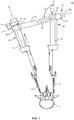
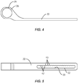
- Spinal correction system 20 includes an elongate member, such as for example, a bridge member 22 defining a longitudinal axis L. Bridge member 22 extends between a first end 24 and a second end 26. It is contemplated that system 20 may include one or a plurality of elongate members 22.
- First end 24 includes a first collar 28 having an inner surface 25, as shown in FIGS. 2 and 3 .
- Inner surface 25 defines a first cavity, such as for example, a first opening 29.
- opening 29 may be variously configured and dimensioned, such as, for example, round, oval, oblong, square, rectangular, polygonal, irregular, uniform, non-uniform, offset, staggered, tapered, consistent or variable, depending on the requirements of a particular application.
- the first cavity may extend through only a portion of first collar 28 and not completely through.
- Opening 29 defines a first axis a.
- First axis a is disposed at a transverse orientation relative to axis L.
- Opening 29 is configured for disposal of a surgical instrument, such as, for example, an extender 34 described below.
- Second end 26 includes a second collar 30 having a second inner surface 27.
- Inner surface 27 defines a second cavity, such as for example, a second opening 31.
- opening 31 may be variously configured and dimensioned, such as, for example, round, oval, oblong, square, rectangular, polygonal, irregular, uniform, non-uniform, offset, staggered, tapered, consistent or variable, depending on the requirements of a particular application.
- the second cavity may extend through only a portion of second collar 30 and not completely through.
- Opening 31 defines a second axis b. Second axis b is disposed at a transverse orientation relative to axis L. Opening 31 is configured for disposal of a surgical instrument, such as, for example, an extender 36 described below.
- Collar 30 includes a threaded opening 60 and a hinge 44.
- Hinge 44 includes a post 62 configured for engagement with opening 60.
- Hinge 44 includes a knob 64 for manipulation.
- Post 62 can be a threaded or smooth pin or other connecting device such as a set screw.
- Hinge 44 is configured for movable disposal relative to second end 26, as described below.
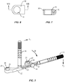
- Second collar 30 includes a flange, such as for example, a shoulder 50, as shown in FIGS. 6 and 7 , configured for preventing translation of second collar 30 onto extender 36, for example, ventral translation of second collar 30 along second extender 36.
- Second end 26 includes an interior surface 33 that defines an elongated cavity, such as, for example, a slot 32 configured for movement of second collar 30 including hinge 44 relative to the bridge member 22 in at least one orientation.
- the at least one orientation includes an angular rotation of axis b relative to axis L through an angle ⁇ and/or an axial translation of second collar 30 along axis L and relative to second end 26. It is contemplated that angle ⁇ includes a range of 0 to 360 degrees.
- Interior surface 33 of slot 32 includes projections 42 that define recesses 43 configured for disposal of post 62.
- Inner surface 33 has a scalloped configuration for adjustable and/or selective fixation of second collar 30 along slot 32. It is contemplated that interior surface 33 can have one or a plurality of projections and/or recesses. It is further contemplated that interior surface 33 may have alternate surface configurations to enhance fixation with hinge 44, such as, for example, rough, arcuate, undulating, mesh, porous, semi-porous, dimpled and/or textured according to the requirements of a particular application.
- Slot 32 extends between a first end 66 and a second end 68. Hinge 44 moves along the length of slot 32 between the first end 66 and the second end 68.
- System 20 includes a first extender 34 and a second extender 36.
- First extender 34 includes an outer surface 38, which is configured for engagement with first collar 28.
- First extender 34 is configured for disposal with a concave portion of a spine.
- Second extender 36 includes an outer surface 40 configured for engagement with the second collar 30.
- Second extender 36 is configured for disposal with a convex portion of the spine. It is contemplated that system 20 may include one or a plurality of first extenders and/or second extenders.
- System 20 includes a dorsal handle 46 disposed intermediate first end 24 and second end 26.
- Handle 46 is disposed perpendicular to axis L.
- Handle 46 includes a gripping surface for manipulation thereof. It is contemplated that handle 46 may be disposed in alternate orientations relative to axis L such as, for example, transverse and/or other angular orientations such as acute or obtuse, co-axial and/or may be offset or staggered.
- System 20 includes a lateral handle 48 disposed adjacent second end 26.
- Handle 48 is disposed co-axial with axis L. It is contemplated that handle 48 may be disposed adjacent first end 28. Handle 48 includes a gripping surface for manipulation thereof. It is contemplated that handle 48 may be disposed in alternate orientations relative to axis L such as, for example, transverse, perpendicular and/or other angular orientations such as acute or obtuse and/or may be offset or staggered.
- Handles 46, 48 are configured for manipulation and application of forces thereto to create one or a plurality of forces and/or moments for application to a body to create for example, a derotation force for a spinal treatment.
- handle 46 and/or handle 48 can be removable for example, to reposition components of system 20 and/or modify treatment. It is envisioned that handles 46, 48 may be employed to displace, pull, twist or align vertebrae, according to the requirements of a particular application.
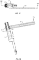
- the components of system 20 are disposable between a first configuration ( FIGS. 9 and 10 ) and a second configuration ( FIGS. 11 and 12 ).
- first configuration no appreciable force is applied to handles 46, 48.
- second configuration no appreciable force is applied to bridge member 22.
- Outer surface 38 of extender 34 is freely slidable within inner surface 25 of collar 28, as shown in FIG. 9 .
- Post 62 is freely translatable with slot 32 and collar 30 is angularly movable relative to second end 26.
- the components of system 20 are moved to the second configuration upon application of forces to handles 46, 48.
- a first force F1 is applied to handle 46, in the direction shown by the corresponding arrow in FIG. 8
- a second force F2 is applied to handle 48, in the direction shown by the corresponding arrow in FIG. 8 .
- Application of forces F1, F2 create a moment M on bridge member 22.
- Application of moment M to bridge member 22 creates a resultant force Fr1 that drives inner surface 25 into fixed engagement with outer surface 38 and creates a resultant force Fr2 which, depending on the anatomy of a body and/or orientation of the components of system 20 including bone fasteners, forces post 62 into fixed engagement with a particular recess 43.
- the fixed engagement of inner surface 25 with outer surface 38 results in a pivot coupling therebetween to fix collar 28 with extender 34.
- first collar 28 is locked with extender 34 and second collar 30 is locked to extender 36.
- the application of forces F1, F2 to handles 46,48 can be maintained and/or increased to apply a treatment force, such as, for example, a derotation force to a body. It is envisioned that this configuration avoids the need for a separate locking structure to fix collars 28, 30 with extenders 34, 36. It is further envisioned that system 20 may be disposed in the second configuration by applying forces F1, F2 in alternate directions to that shown in FIG. 8 , such as an opposite direction. In one embodiment, collar 28 can be locked into place along first extender 34 with a locking collar 54, as shown in FIG. 1 .
- spinal correction system 20 In assembly, operation and use, spinal correction system 20, similar to the system described above, is employed with a surgical procedure, such as, for example, a correction treatment to treat adolescent idiopathic scoliosis and/or Scheuermann's kyphosis of a spine. It is contemplated that one or all of the components of spinal correction system 20 can be delivered or utilized as a pre-assembled device or can be assembled in situ.
- spinal correction system 20 can be employed with a surgical correction treatment of an applicable condition or injury of an affected section of a spinal column and adjacent areas within a body, such as, for example, vertebrae V, as shown in FIG. 1 . It is envisioned that spinal correction system 20 may be employed with one or a plurality of vertebrae.
- spinal correction system 20 can be used in any existing surgical method or technique including open surgery, mini-open surgery, minimally invasive surgery and percutaneous surgical implantation, whereby vertebrae V is accessed through a mini-incision, or sleeve that provides a protected passageway to the area. Once access to the surgical site is obtained, the particular surgical procedure can be performed for treating the spine disorder.
- a cutting instrument (not shown) creates a surgical pathway for implantation of components of spinal correction system 20.
- a preparation instrument (not shown) can be employed to prepare tissue surfaces of vertebrae V, as well as for aspiration and irrigation of a surgical region according to the requirements of a particular surgical application.
- Pilot holes are made bilaterally in selected levels of vertebrae V for receiving bone fasteners 70, 72.
- Extenders 34, 36 are oriented for manipulation, alignment and capture of bone fasteners 70, 72.
- First extender 34 is configured for disposal with a concave portion of a selected vertebra of vertebrae V and second extender 36 is configured for disposal with a convex portion of a selected vertebra of vertebrae V.
- Extenders 34, 36 are attached with vertebrae V via bone fasteners 70, 72, such that the components of system 20 are disposed in the first configuration, as described above and shown in FIGS. 9 and 10 .
- Force F1 is applied to handle 46, in the direction shown by the corresponding arrow in FIG. 8
- force F2 is applied to handle 48, in the direction shown by the corresponding arrow in FIG. 8 , to create moment M on bridge member 22.
- Moment M creates force Fr1 that drives inner surface 25 into fixed engagement with outer surface 38 and creates force Fr2 to force post 62 into fixed engagement with a recess 43, as shown in FIG. 1 .
- First collar 28 is locked with extender 34 and second collar 30 is locked to extender 36 such that spinal correction system 20 is disposed in the second configuration.
- the application of forces F1, F2 to handles 46, 48 can be maintained and/or increased to apply a derotation force to vertebrae V.
- microsurgical and image guided technologies may be employed to access, view and repair spinal deterioration or damage, with the aid of spinal correction system 20.
- the surgical instruments and assemblies are removed and the incision is closed.
- spinal correction system 20 may be employed to treat progressive idiopathic scoliosis with or without sagittal deformity in either infantile or juvenile patients, including but not limited to prepubescent children, adolescents from 10-12 years old with continued growth potential, and/or older children whose growth spurt is late or who otherwise retain growth potential. It is further contemplated that the components of spinal correction system 20 and method of use may be used to prevent or minimize curve progression in individuals of various ages.
- a spinal correction system 20 similar to system 20 described above with regard to FIGS. 1-12 , includes a plurality ofbridge members 122.
- the plurality of bridge members 122 define longitudinal axes L1, L2 and L3, respectively.
- Each bridge member 122 extends between a first end 124 and a second end 126.
- First end 124 includes a first collar 128 having an inner surface 125.
- Inner surface 125 defines a first opening 129.
- Second end 126 includes a second collar 130 having an inner surface 127.
- Inner surface 127 defines a second opening 131.
- First openings 129 define first axes a1, a2 and a3, respectively, oriented transverse and movable relative to the respective axes L1, L2 or L3.
- Second openings 131 define second axes b1, b2 and b3, respectively, oriented transverse to the respective axes L1, L2 or L3.
- Second end 126 includes an interior surface 133 defining an elongated slot 132 configured for selectively moving second collar 130 relative to bridge member 122 in at least one orientation, similar to that described above, relative to axes L1, L2 or L3.
- a plurality of first extenders 134 each having an outer surface 138, which is configured for engagement with first collar 128.
- a plurality of second extenders 136 each having an outer surface 140 configured for engagement with second collar 130.
- the plurality of bridge members 122 is disposed in a linked configuration. Elongated slots 132 are configured for disposal of a link member 158 for linking the elongated members. Linking the plurality of bridge members 122 allows for global derotation of multiple vertebrae.
- Each of the bridge members 22 is disposable between a first configuration and a second configuration, as described above with regard to FIGS. 1-12 . It is contemplated that each of the plurality of bridge members 22 may include handles, such as handles 46, 48 described above, to apply forces to system 20, or may include one set of handles 46, 48 for all bridge members 22.
- a spinal correction system 20 similar to system 20 described above with regard to FIGS. 1-12 , includes a bridge member, such as, for example, a frame 210.
- Frame 210 extends between a first end 224 and a second end 226.
- First end 224 includes a first collar 228 having an inner surface 225.
- Inner surface 225 defines a plurality of cavities including openings 229a, 229b, 229c.
- Opening 229a has an elongated configuration
- opening 229b has a circular configuration
- opening 229c has an elongated configuration.
- Openings 229a, 229b, 229c are each configured for disposal of a surgical instrument, such as, for example, extenders 234. It is contemplated that openings 229a, 229b, 229c may have other configurations, such as, for example, a singular elongated opening.
- Second end 226 includes a second collar 230 having a second inner surface 227.
- Inner surface 227 defines a plurality of cavities including openings 231a, 231b, 231c.
- Opening 231a has an elongated configuration
- opening 231b has a circular configuration
- opening 231c has an elongated configuration.
- Openings 231a, 231b, 231c are each configured for disposal of a surgical instrument, such as, for example, extenders 236. It is contemplated that openings 231a, 231b, 231c may have other configurations, such as, for example, a singular elongated opening.
- Collar 230 includes a pair of opposing hinges 244 disposed on lateral sides of frame 210. Collar 230 includes threaded openings 260 that receive hinges 244. Each hinge 244 includes a post 262 configured for engagement with opening 260. Hinge 244 is configured for movable disposal relative to second end 226. Second collar 230 includes a shoulder 250 configured for preventing translation of second extender 236 out of second collar 236.
- Second end 226 includes an interior surface 233 that defines an elongated slot 232 configured for movement of second collar 230 including hinge 244 relative to frame 210 in at least one orientation, as described above.
- Interior surface 233 of slot 232 includes projections 242 that define recesses 243 configured for disposal of post 262. Hinge 244 moves along the length of slot 232.
- System 20 includes a dorsal handle 246, a first side handle 248 and a second side handle 249, similar to the handles described above.
- Handles 246, 248, 249 are configured for manipulation and application of forces thereto to create one or a plurality of forces and/or moments for application to a body to create for example, a derotation force for a spinal treatment.
- the components of system 20 are disposable between a first configuration and a second configuration. In the first configuration, no appreciable force is applied to frame 210, similar to that described above.
- the components of system 20 are moved to the second configuration upon application of forces to handles 246, 248.
- a first force F10 is applied to handle 246, in the direction shown by the corresponding arrow in FIG. 14
- a second force F20 is applied to handle 248, in the direction shown by the corresponding arrow in FIG. 14 .
- Application of forces F10, F20 create a moment M1 on frame 210.
- Application of moment M1 to frame 210 creates a resultant force Fr10 that drives inner surface 225 into fixed engagement with outer surfaces 238 and creates a resultant force Fr20 which, depending on the anatomy of a body and/or orientation of the components of system 20 including bone fasteners, forces opposing posts 262 into fixed engagement with particular opposing recesses 243.
- collar 228 is locked with extenders 234 and second collar 230 is locked to extenders 236.
- the application of forces F10, F20 to handles 246,248 can be maintained and/or increased to apply a treatment force, such as, for example, a derotation force to a body.
- the components of system 20 are moved to the second configuration upon application of forces to handles 246, 249, such that a force F10 is applied to handle 246, and a force is applied to handle 249 in a downward direction.
Description
- The present disclosure generally relates to medical devices for the treatment of musculoskeletal disorders, and more particularly to a surgical system for correction of a spine disorder.
- Spinal pathologies and disorders such as scoliosis and other curvature abnormalities, kyphosis, degenerative disc disease, disc herniation, osteoporosis, spondylolisthesis, stenosis, tumor, and fracture may result from factors including trauma, disease and degenerative conditions caused by injury and aging. Spinal disorders typically result in symptoms including deformity, pain, nerve damage, and partial or complete loss of mobility.
- Non-surgical treatments, such as medication, rehabilitation and exercise can be effective, however, may fail to relieve the symptoms associated with these disorders. Surgical treatment of these spinal disorders includes correction, fusion, fixation, discectomy, laminectomy and implantable prosthetics. Correction treatments may employ implants that are manipulated for engagement with vertebrae in the spinal column in an effort to position and align one or more vertebrae. This disclosure describes an improvement over these prior art technologies.
- Spinal correction systems are known from
FR 2 887 756 A1 US 2011/0172714 A1 ,EP 2 305 154 A1 ,US 2010/0298885 A1 , andUS 2011/0106082 A1 . - According to the present invention, a spinal correction system according to claim 1 is provided. Examples of such a system are defined in the dependent claims.
- The methods not covered by the claims represent background art that is useful in understanding the invention.
- Accordingly, a surgical system for correction of a spine disorder is provided. In one particular embodiment, in accordance with the principles of the present disclosure, a spinal correction system comprises at least one elongate member defining a longitudinal axis and extending between a first end and a second end. The first end includes a first inner surface defining a first cavity and the second end includes a collar having a second inner surface defining a second cavity. The second cavity is movable relative to the elongate member in at least one orientation. The second end includes an interior surface defining an elongated cavity. At least one first extender defines a first outer surface configured for engagement with the first inner surface. At least one second extender defines a second outer surface configured for engagement with the second inner surface. The at least one elongate member is disposable between a first configuration and a second configuration such that the second cavity is movable in the at least one orientation to a position such that the first inner surface is forcibly disposed in a fixed engagement with the first outer surface and the interior surface is forcibly disposed in a fixed engagement with at least a portion of the collar.
- In one embodiment, the spinal correction system comprises at least one bridge member defining a first longitudinal axis and extending between a first end and a second end. The first end includes a first collar defining a first opening and the second end includes a second collar defining a second opening that defines a second axis oriented transverse to the first longitudinal axis. The second end further including an interior surface defining an elongated slot configured for moving the second collar relative to the bridge member in an angular orientation and an axial orientation. At least one first extender defines an outer surface configured for engagement with the first collar and disposal with a concave portion of a spine. At least one second extender defines an outer surface configured for engagement with the second collar and disposal with a convex portion of the spine. The at least one bridge member is disposable between a first configuration and a second configuration such that the second collar is movable to a position such that the second axis is selectively angularly oriented relative to the first longitudinal axis and the second collar is selectively axially oriented relative to the slot such that the first inner surface is forcibly disposed in a pivot coupling with the outer surface of the first extender and the interior surface is forcibly disposed in a fixed engagement with at least a portion of the second collar.
- In one embodiment, the spinal correction system comprises a plurality of bridge members. Each bridge member defines a longitudinal axis and extending between a first end and a second end. The first end of each bridge member includes a first collar defining a first opening and the second end of each bridge member including a second collar defining a second opening that defines a second axis oriented transverse to the respective longitudinal axis. The second end of each bridge member further includes an interior surface defining an elongated slot configured for moving the second collar relative to the respective elongate member in an angular orientation and an axial orientation. The system further comprises a plurality of concave extenders. Each concave extender defines an outer surface configured for engagement with the first collar of one of the plurality of bridge members. The system further comprises a plurality of convex extenders. Each convex extender defines an outer surface configured for engagement with the second collar of a one of the plurality of bridge members. A link member extends through the slots of each of the bridge members. The plurality of bridge members are collectively disposable between a first configuration and a second configuration such that the second collar of each bridge member is movable to a position such that the second axis is angularly oriented relative to the first longitudinal axis and the second collar is axially oriented relative to the slot such that the first collar is forcibly disposed in a pivot coupling with the outer surface of the first extender and the second collar is forcibly disposed in a fixed engagement with the interior surface so that the plurality of bridge members are configured for derotation of vertebrae such that a first force oriented in a first direction is applied to the first end of each bridge member and a second force oriented in a second direction is applied to the second end of each bridge member.
- The present disclosure will become more readily apparent from the specific description accompanied by the following drawings, in which:
-
FIG. 1 is a side view of one particular embodiment of a system in accordance with the principles of the present disclosure; -
FIG. 2 is a perspective view of components of the system shown inFIG. 1 ; -
FIG. 3 is a perspective view of components of the system shown inFIG. 1 with parts separated; -
FIG. 4 is a top view of an elongated member of the system shown inFIG. 1 ; -
FIG. 5 is a side view of the elongated member shown inFIG. 2 ; -
FIG. 6 is a top view of a collar of the system shown inFIG. 1 ; -
FIG. 7 is a side cross section view of the collar shown inFIG. 6 taken along lines VII-VII; -
FIG. 8 is a perspective view of components of the system shown inFIG. 1 ; -
FIG. 9 is a top view of components of the system shown inFIG. 1 ; -
FIG. 10 is a side view, in part cross section, of the components of the system taken along the lines X-X shown inFIG. 9 ; -
FIG. 11 is a top view of components of the system shown inFIG. 1 ; -
FIG. 12 is a side view, in part cross section, of the components of the system taken along the lines XII-XII shown inFIG. 11 ; -
FIG. 13 is a perspective view of one embodiment of the system shown inFIG. 1 ; -
FIG. 14 is a perspective view of one embodiment of the system shown inFIG. 1 ; -
FIG. 15 is a perspective view of an elongated member of the system shown inFIG. 14 ; -
FIG. 16 is a perspective view of the elongated member shown inFIG. 15 with parts separated; -
FIG. 17 is a top view of the system shown inFIG. 14 ; and -
FIG. 18 is a side view of the system shown inFIG. 14 . - Like reference numerals indicate similar parts throughout the figures.
- The exemplary embodiments of the spinal correction system disclosed are discussed in terms of medical devices for the treatment of musculoskeletal disorders and more particularly, in terms of a spinal correction system that facilitates implant delivery and treatment of a spine. It is envisioned that the spinal correction system can include extenders, reducers and translators, which can be used to introduce a vertebral construct such as a rod to a bone fastener, such as a bone anchor or bone screw. For example, an extender can include bone anchor attachment features on one or both sides of the instrument. It is contemplated that the system may be used with a reducer assembly to introduce a rod into a bone fastener.
- In one embodiment, the system includes a segmental derotation apparatus, which comprises an adjustable link for connecting at least two screw extenders in an axial plane. The segmental derotation apparatus includes a link having a bridge bar and a hinge. The bridge bar connects to a screw extender, for example, a concave extender, while the hinge connects to another screw extender, for example, a convex extender. The adjustable link provides for varying distances between extenders by having a scalloped slot that allows movement when external force is not applied. Upon application of external forces, the hinge locks into one of the scallops of the scalloped slots to provide rigidity along the bridge bar. The bridge bar connects to an extender by sliding over a top surface of the extender. The hinge also slides over an extender. The hinge may include a lip, such as, for example, a shoulder that prevents ventral translation of the extender to maintain the hinge from sliding down the extender shaft. By applying a downward force to a handle or hinge side of the bridge bar, a moment is applied about the hinge creating a pivot coupling between the bridge bar of an associated extender. It is contemplated that a setscrew could be used to lock the bridge bar onto an extender. It is further contemplated that a linking member may be employed to link multiple bridge bars together so that all levels operate as one global unit.
- In one embodiment, the system includes a global derotation apparatus, which comprises locking onto only one vertebral level in an axial plane. For example, two levels could be linked together. It is envisioned that one or two levels above and below an apex can be locked as a unit so that correction of the unit can be achieved. It is contemplated that the system can be employed with a method that allows for distraction and kyphosis adjustments while the unit is attached with the extenders.
- It is envisioned that the spinal correction system may include instruments that are connected or attached to an extender(s) such as, for example, a lateral translation handle or derotation instruments. In one embodiment, one or all of the components of the surgical system are disposable, peel-pack, prepacked sterile devices used with a spinal correction system. One or all of the components of the spinal correction system may be reusable. The spinal correction system may be configured as a kit with multiple sized and configured components.
- It is envisioned that the present disclosure may be employed to treat spinal disorders such as, for example, degenerative disc disease, disc herniation, osteoporosis, spondylolisthesis, stenosis, scoliosis and other curvature abnormalities, kyphosis, tumor and fractures. It is contemplated that the present disclosure may be employed with other osteal and bone related applications, including those associated with diagnostics and therapeutics. It is further contemplated that the disclosed surgical system may be alternatively employed in a surgical treatment with a patient in a prone or supine position, and/or employ various surgical approaches to the spine, including anterior, posterior, posterior mid-line, direct lateral, postero-lateral, and/or antero-lateral approaches, and in other body regions. The present disclosure may also be alternatively employed with procedures for treating the lumbar, cervical, thoracic and pelvic regions of a spinal column. The system of the present disclosure may also be used on animals, bone models and other non-living substrates, such as, for example, in training, testing and demonstration.
- The present disclosure may be understood more readily by reference to the following detailed description of the disclosure taken in connection with the accompanying drawing figures, which form a part of this disclosure. It is to be understood that this disclosure is not limited to the specific devices conditions or parameters described and/or shown herein, and that the terminology used herein is for the purpose of describing particular embodiments by way of example only and is not intended to be limiting of the claimed disclosure. Also, as used in the specification and including the appended claims, the singular forms "a," "an," and "the" include the plural, and reference to a particular numerical value includes at least that particular value, unless the context clearly dictates otherwise. Ranges may be expressed herein as from "about" or "approximately" one particular value and/or to "about" or "approximately" another particular value. When such a range is expressed, another embodiment includes from the one particular value and/or to the other particular value. Similarly, when values are expressed as approximations, by use of the antecedent "about," it will be understood that the particular value forms another embodiment. It is also understood that all spatial references, such as, for example, horizontal, vertical, top, upper, lower, bottom, left and right, are for illustrative purposes only and can be varied within the scope of the disclosure. For example, the references "upper" and "lower" are relative and used only in the context to the other, and are not necessarily "superior" and "inferior".
- Further, as used in the specification and including the appended claims, "treating" or "treatment" of a disease or condition refers to performing a procedure that may include administering one or more drugs to a patient (human, normal or otherwise or other mammal), in an effort to alleviate signs or symptoms of the disease or condition. Alleviation can occur prior to signs or symptoms of the disease or condition appearing, as well as after their appearance. Thus, treating or treatment includes preventing or prevention of disease or undesirable condition (e.g., preventing the disease from occurring in a patient, who may be predisposed to the disease but has not yet been diagnosed as having it). In addition, treating or treatment does not require complete alleviation of signs or symptoms, does not require a cure, and specifically includes procedures that have only a marginal effect on the patient. Treatment can include inhibiting the disease, e.g., arresting its development, or relieving the disease, e.g., causing regression of the disease. For example, treatment can include reducing acute or chronic inflammation; alleviating pain and mitigating and inducing re-growth of new ligament, bone and other tissues; as an adjunct in surgery; and/or any repair procedure. Also, as used in the specification and including the appended claims, the term "tissue" includes soft tissue, ligaments, tendons, cartilage and/or bone unless specifically referred to otherwise.
- The following discussion includes a description of a spinal correction system in accordance with the principles of the present disclosure. Alternate embodiments are also disclosed. Reference will now be made in detail to the exemplary embodiments
of the present disclosure, which are illustrated in the accompanying figures. Turning now toFIGS. 1-12 , there is illustrated components of a surgical system, such as, for example, aspinal correction system 20 in accordance with the principles of the present disclosure. - The components of
spinal correction system 20 can be fabricated from biologically acceptable materials suitable for medical applications, including metals, synthetic polymers, ceramics and bone material and/or their composites, depending on the particular application and/or preference of a medical practitioner. For example, the components of spinal correction system 20, individually or collectively, can be fabricated from materials such as stainless steel alloys, commercially pure titanium, titanium alloys, Grade 5 titanium, super-elastic titanium alloys, cobalt-chrome alloys, stainless steel alloys, superelastic metallic alloys (e.g., Nitinol, super elasto-plastic metals, such as GUM METAL® manufactured by Toyota Material Incorporated of Japan), ceramics and composites thereof such as calcium phosphate (e.g., SKELITE™ manufactured by Biologix Inc.), thermoplastics such as polyaryletherketone (PAEK) including polyetheretherketone (PEEK), polyetherketoneketone (PEKK) and polyetherketone (PEK), carbon-PEEK composites, PEEK-BaSO4 polymeric rubbers, polyethylene terephthalate (PET), fabric, silicone, polyurethane, silicone-polyurethane copolymers, polymeric rubbers, polyolefin rubbers, hydrogels, semi-rigid and rigid materials, elastomers, rubbers, thermoplastic elastomers, thermoset elastomers, elastomeric composites, rigid polymers including polyphenylene, polyamide, polyimide, polyetherimide, polyethylene, epoxy, bone material including autograft, allograft, xenograft or transgenic cortical and/or corticocancellous bone, and tissue growth or differentiation factors, partially resorbable materials, such as, for example, composites of metals and calcium-based ceramics, composites of PEEK and calcium based ceramics, composites of PEEK with resorbable polymers, totally resorbable materials, such as, for example, calcium based ceramics such as calcium phosphate, tri-calcium phosphate (TCP), hydroxyapatite (HA)-TCP, calcium sulfate, or other resorbable polymers such as polyaetide, polyglyclolide, polytyrosine carbonate, polycaroplaetohe and their combinations. Various components ofspinal correction system 20 may have material composites, including the above materials, to achieve various desired characteristics such as strength, rigidity, elasticity, compliance, biomechanical performance, durability and radiolucency or imaging preference. The components ofspinal correction system 20, individually or collectively, may also be fabricated from a heterogeneous material such as a combination of two or more of the above-described materials. The components of spinal correction
system 20 may be monolithically formed, integrally connected or include fastening elements and/or instruments, as described herein. -
Spinal correction system 20 is employed, for example, with an open or mini-open, minimal access and/or minimally invasive including percutaneous surgical technique for engagement with an implant, such as, for example, a bone fastener for a correction treatment at a surgical site within a body of a patient, for example, a section of a spine to treat various spine pathologies, such as, for example, adolescent idiopathic scoliosis and Scheuermann's kyphosis. In one embodiment, the components ofspinal correction system 20 are configured to deliver and introduce an implant, such as, for example, a vertebral construct such as a rod to a bone fastener. -
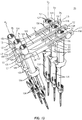
Spinal correction system 20 includes an elongate member, such as for example, abridge member 22 defining a longitudinal axisL. Bridge member 22 extends between afirst end 24 and asecond end 26. It is contemplated thatsystem 20 may include one or a plurality ofelongate members 22. -
First end 24 includes afirst collar 28 having aninner surface 25, as shown inFIGS. 2 and 3 .Inner surface 25 defines a first cavity, such as for example, afirst opening 29. It is envisioned that opening 29 may be variously configured and dimensioned, such as, for example, round, oval, oblong, square, rectangular, polygonal, irregular, uniform, non-uniform, offset, staggered, tapered, consistent or variable, depending on the requirements of a particular application. In one embodiment, the first cavity may extend through only a portion offirst collar 28 and not completely through.Opening 29 defines a first axis a. First axis a is disposed at a transverse orientation relative toaxis L. Opening 29 is configured for disposal of a surgical instrument, such as, for example, anextender 34 described below. -
Second end 26 includes asecond collar 30 having a secondinner surface 27.Inner surface 27 defines a second cavity, such as for example, asecond opening 31. It is envisioned that opening 31 may be variously configured and dimensioned, such as, for example, round, oval, oblong, square, rectangular, polygonal, irregular, uniform, non-uniform, offset, staggered, tapered, consistent or variable, depending on the requirements of a particular application. In one embodiment, the second cavity may extend through only a portion ofsecond collar 30 and not completely through.Opening 31 defines a second axis b. Second axis b is disposed at a transverse orientation relative toaxis L. Opening 31 is configured for disposal of a surgical instrument, such as, for example, anextender 36 described below. -
Collar 30 includes a threadedopening 60 and ahinge 44.Hinge 44 includes apost 62 configured for engagement withopening 60.Hinge 44 includes aknob 64 for manipulation.Post 62 can be a threaded or smooth pin or other connecting device such as a set screw.Hinge 44 is configured for movable disposal relative tosecond end 26, as described below. -
Second collar 30 includes a flange, such as for example, ashoulder 50, as shown inFIGS. 6 and 7 , configured for preventing translation ofsecond collar 30 ontoextender 36, for example, ventral translation ofsecond collar 30 alongsecond extender 36.Second end 26 includes aninterior surface 33 that defines an elongated cavity, such as, for example, aslot 32 configured for movement ofsecond collar 30 includinghinge 44 relative to thebridge member 22 in at least one orientation. In one embodiment, the at least one orientation includes an angular rotation of axis b relative to axis L through an angle α and/or an axial translation ofsecond collar 30 along axis L and relative tosecond end 26. It is contemplated that angle α includes a range of 0 to 360 degrees. -
Interior surface 33 ofslot 32 includesprojections 42 that define recesses 43 configured for disposal ofpost 62.Inner surface 33 has a scalloped configuration for adjustable and/or selective fixation ofsecond collar 30 alongslot 32. It is contemplated thatinterior surface 33 can have one or a plurality of projections and/or recesses. It is further contemplated thatinterior surface 33 may have alternate surface configurations to enhance fixation withhinge 44, such as, for example, rough, arcuate, undulating, mesh, porous, semi-porous, dimpled and/or textured according to the requirements of a particular application.Slot 32 extends between afirst end 66 and asecond end 68.Hinge 44 moves along the length ofslot 32 between thefirst end 66 and thesecond end 68. -
System 20 includes afirst extender 34 and asecond extender 36.First extender 34 includes anouter surface 38, which is configured for engagement withfirst collar 28.First extender 34 is configured for disposal with a concave portion of a spine.Second extender 36 includes anouter surface 40 configured for engagement with thesecond collar 30.Second extender 36 is configured for disposal with a convex portion of the spine. It is contemplated thatsystem 20 may include one or a plurality of first extenders and/or second extenders. -
System 20 includes adorsal handle 46 disposed intermediatefirst end 24 andsecond end 26.Handle 46 is disposed perpendicular to axis L. Handle 46 includes a gripping surface for manipulation thereof. It is contemplated that handle 46 may be disposed in alternate orientations relative to axis L such as, for example, transverse and/or other angular orientations such as acute or obtuse, co-axial and/or may be offset or staggered. -
System 20 includes alateral handle 48 disposed adjacentsecond end 26.Handle 48 is disposed co-axial with axis L. It is contemplated that handle 48 may be disposed adjacentfirst end 28.Handle 48 includes a gripping surface for manipulation thereof. It is contemplated that handle 48 may be disposed in alternate orientations relative to axis L such as, for example, transverse, perpendicular and/or other angular orientations such as acute or obtuse and/or may be offset or staggered. -
Handles system 20 and/or modify treatment. It is envisioned that handles 46, 48 may be employed to displace, pull, twist or align vertebrae, according to the requirements of a particular application. - In operation, the components of
system 20 are disposable between a first configuration (FIGS. 9 and 10 ) and a second configuration (FIGS. 11 and 12 ). In the first configuration, no appreciable force is applied tohandles bridge member 22.Outer surface 38 ofextender 34 is freely slidable withininner surface 25 ofcollar 28, as shown inFIG. 9 .Post 62 is freely translatable withslot 32 andcollar 30 is angularly movable relative tosecond end 26. - The components of
system 20 are moved to the second configuration upon application of forces to handles 46, 48. A first force F1 is applied to handle 46, in the direction shown by the corresponding arrow inFIG. 8 , and a second force F2 is applied to handle 48, in the direction shown by the corresponding arrow inFIG. 8 . Application of forces F1, F2 create a moment M onbridge member 22. Application of moment M to bridgemember 22 creates a resultant force Fr1 that drivesinner surface 25 into fixed engagement withouter surface 38 and creates a resultant force Fr2 which, depending on the anatomy of a body and/or orientation of the components ofsystem 20 including bone fasteners, forces post 62 into fixed engagement with aparticular recess 43. In one embodiment, the fixed engagement ofinner surface 25 withouter surface 38 results in a pivot coupling therebetween to fixcollar 28 withextender 34. - In the second configuration,
first collar 28 is locked withextender 34 andsecond collar 30 is locked toextender 36. The application of forces F1, F2 tohandles collars extenders system 20 may be disposed in the second configuration by applying forces F1, F2 in alternate directions to that shown inFIG. 8 , such as an opposite direction. In one embodiment,collar 28 can be locked into place alongfirst extender 34 with a lockingcollar 54, as shown inFIG. 1 . - In assembly, operation and use,
spinal correction system 20, similar to the system described above, is employed with a surgical procedure, such as, for example, a correction treatment to treat adolescent idiopathic scoliosis and/or Scheuermann's kyphosis of a spine. It is contemplated that one or all of the components ofspinal correction system 20 can be delivered or utilized as a pre-assembled device or can be assembled in situ. - For example,
spinal correction system 20 can be employed with a surgical correction treatment of an applicable condition or injury of an affected section of a spinal column and adjacent areas within a body, such as, for example, vertebrae V, as shown inFIG. 1 . It is envisioned thatspinal correction system 20 may be employed with one or a plurality of vertebrae. - In use, to treat vertebrae V, a medical practitioner obtains access to a surgical site including vertebrae V in any appropriate manner, such as through incision and retraction of tissues. It is envisioned that
spinal correction system 20 can be used in any existing surgical method or technique including open surgery, mini-open surgery, minimally invasive surgery and percutaneous surgical implantation, whereby vertebrae V is accessed through a mini-incision, or sleeve that provides a protected passageway to the area. Once access to the surgical site is obtained, the particular surgical procedure can be performed for treating the spine disorder. - An incision is made in the body of a patient and a cutting instrument (not shown) creates a surgical pathway for implantation of components of
spinal correction system 20. A preparation instrument (not shown) can be employed to prepare tissue surfaces of vertebrae V, as well as for aspiration and irrigation of a surgical region according to the requirements of a particular surgical application. - Pilot holes (not shown) are made bilaterally in selected levels of vertebrae V for receiving
bone fasteners Extenders bone fasteners First extender 34 is configured for disposal with a concave portion of a selected vertebra of vertebrae V andsecond extender 36 is configured for disposal with a convex portion of a selected vertebra of vertebrae V. -
Extenders bone fasteners system 20 are disposed in the first configuration, as described above and shown inFIGS. 9 and 10 . Force F1 is applied to handle 46, in the direction shown by the corresponding arrow inFIG. 8 , and force F2 is applied to handle 48, in the direction shown by the corresponding arrow inFIG. 8 , to create moment M onbridge member 22. Moment M creates force Fr1 that drivesinner surface 25 into fixed engagement withouter surface 38 and creates force Fr2 to forcepost 62 into fixed engagement with arecess 43, as shown inFIG. 1 . -
First collar 28 is locked withextender 34 andsecond collar 30 is locked to extender 36 such thatspinal correction system 20 is disposed in the second configuration. The application of forces F1, F2 tohandles - It is envisioned that the use of microsurgical and image guided technologies may be employed to access, view and repair spinal deterioration or damage, with the aid of
spinal correction system 20. Upon completion of the procedure, the surgical instruments and assemblies are removed and the incision is closed. - It is contemplated that the components of
spinal correction system 20 may be employed to treat progressive idiopathic scoliosis with or without sagittal deformity in either infantile or juvenile patients, including but not limited to prepubescent children, adolescents from 10-12 years old with continued growth potential, and/or older children whose growth spurt is late or who otherwise retain growth potential. It is further contemplated that the components ofspinal correction system 20 and method of use may be used to prevent or minimize curve progression in individuals of various ages. - In one embodiment, as shown in
FIG. 13 , aspinal correction system 20, similar tosystem 20 described above with regard toFIGS. 1-12 , includes aplurality ofbridge members 122. The plurality ofbridge members 122 define longitudinal axes L1, L2 and L3, respectively. Eachbridge member 122 extends between afirst end 124 and asecond end 126.First end 124 includes afirst collar 128 having aninner surface 125.Inner surface 125 defines afirst opening 129.Second end 126 includes asecond collar 130 having aninner surface 127.Inner surface 127 defines asecond opening 131.First openings 129 define first axes a1, a2 and a3, respectively, oriented transverse and movable relative to the respective axes L1, L2 or L3.Second openings 131 define second axes b1, b2 and b3, respectively, oriented transverse to the respective axes L1, L2 or L3. -
Second end 126 includes aninterior surface 133 defining anelongated slot 132 configured for selectively movingsecond collar 130 relative to bridgemember 122 in at least one orientation, similar to that described above, relative to axes L1, L2 or L3. A plurality offirst extenders 134, each having anouter surface 138, which is configured for engagement withfirst collar 128. A plurality ofsecond extenders 136, each having anouter surface 140 configured for engagement withsecond collar 130. - The plurality of
bridge members 122 is disposed in a linked configuration.Elongated slots 132 are configured for disposal of alink member 158 for linking the elongated members. Linking the plurality ofbridge members 122 allows for global derotation of multiple vertebrae. Each of thebridge members 22 is disposable between a first configuration and a second configuration, as described above with regard toFIGS. 1-12 . It is contemplated that each of the plurality ofbridge members 22 may include handles, such ashandles system 20, or may include one set ofhandles bridge members 22. - In one embodiment, as shown in
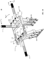
FIGS. 14-18 , aspinal correction system 20, similar tosystem 20 described above with regard toFIGS. 1-12 , includes a bridge member, such as, for example, aframe 210.Frame 210 extends between afirst end 224 and asecond end 226. -
First end 224 includes afirst collar 228 having aninner surface 225.Inner surface 225 defines a plurality ofcavities including openings Opening 229a has an elongated configuration,opening 229b has a circular configuration and opening 229c has an elongated configuration.Openings extenders 234. It is contemplated thatopenings -
Second end 226 includes asecond collar 230 having a secondinner surface 227.Inner surface 227 defines a plurality ofcavities including openings Opening 231a has an elongated configuration,opening 231b has a circular configuration and opening 231c has an elongated configuration.Openings extenders 236. It is contemplated thatopenings -
Collar 230 includes a pair of opposinghinges 244 disposed on lateral sides offrame 210.Collar 230 includes threadedopenings 260 that receive hinges 244. Eachhinge 244 includes apost 262 configured for engagement withopening 260.Hinge 244 is configured for movable disposal relative tosecond end 226.Second collar 230 includes ashoulder 250 configured for preventing translation ofsecond extender 236 out ofsecond collar 236. -
Second end 226 includes aninterior surface 233 that defines anelongated slot 232 configured for movement ofsecond collar 230 includinghinge 244 relative to frame 210 in at least one orientation, as described above.Interior surface 233 ofslot 232 includesprojections 242 that definerecesses 243 configured for disposal ofpost 262. Hinge 244 moves along the length ofslot 232. -
System 20 includes adorsal handle 246, afirst side handle 248 and asecond side handle 249, similar to the handles described above.Handles system 20 are disposable between a first configuration and a second configuration. In the first configuration, no appreciable force is applied to frame 210, similar to that described above. - In one embodiment, the components of
system 20 are moved to the second configuration upon application of forces tohandles FIG. 14 , and a second force F20 is applied to handle 248, in the direction shown by the corresponding arrow inFIG. 14 . Application of forces F10, F20 create a moment M1 onframe 210. Application of moment M1 to frame 210 creates a resultant force Fr10 that drivesinner surface 225 into fixed engagement withouter surfaces 238 and creates a resultant force Fr20 which, depending on the anatomy of a body and/or orientation of the components ofsystem 20 including bone fasteners,forces opposing posts 262 into fixed engagement with particular opposing recesses 243. In the second configuration,collar 228 is locked withextenders 234 andsecond collar 230 is locked to extenders 236. The application of forces F10, F20 to handles 246,248 can be maintained and/or increased to apply a treatment force, such as, for example, a derotation force to a body. - In one embodiment, the components of
system 20 are moved to the second configuration upon application of forces tohandles
Claims (9)
- A spinal correction system (20) comprising:at least one bridge member (22) defining a longitudinal axis (L) and extending between a first end (24) and a second end (26), the first end (24) including a first inner surface (25) defining a first cavity (29) and the second end (26) including a collar (30) having a second inner surface (27) defining a second cavity (31), the second cavity (31) being movable relative to the bridge member (22) in at least one orientation, the second end (26) comprising an interior surface (33) defining an elongated cavity (32), wherein the interior surface (33) includes a plurality of projections (42) defining a plurality of recesses (43) therebetween;at least one first extender (34) defining a first outer surface (38) configured for engagement with the first inner surface (25); andat least one second extender (36) defining a second outer surface (40) configured for engagement with the second inner surface (27),wherein the at least one bridge member (22) is disposable between a first configuration and a second configuration, wherein the bridge member (22) is disposed in the first configuration when no forces are applied to it, and is disposed in the second configuration when forces (F1, F2) are applied to it to create a moment (M) on the bridge member (22), thereby moving the second cavity (31) in the at least one orientation to a position in which the first inner surface (25) is forcibly disposable in a fixed engagement with the first outer surface (38) and the interior surface (33) is forcibly disposed in a fixed engagement with at least a portion of the collar (30), the system (20) further comprising at least one handle (46, 48) attached with the at least one bridge member (22) to apply the moment (M) to the bridge member (22) to dispose the bridge member (22) in the second configuration, wherein in the first configuration the collar (30) is freely translatable within the elongated cavity (32), and in the second configuration the collar (30) is disposed in one of the plurality of recesses (43).
- The system (20) as recited in claim 1, wherein the fixed engagement includes a pivot coupling between the first inner surface (25) and the first outer surface (38).
- The system (20) as recited in claim 1, wherein the elongated cavity (32) includes a slot and the collar (30) includes a post (62) configured for fixation with the interior surface (33).
- The system (20) as recited in claim 1, wherein the collar (30) includes a hinge (44) having a post (62) configured to fix the collar (30) with the bridge member (22) in the position.
- The system (20) as recited in claim 1, wherein the interior surface (33) includes a scalloped configuration.
- The system (20) as recited in claim 1, wherein the second cavity (31) defines a second axis (b) oriented transverse and is movable relative to the longitudinal axis (L).
- The system (20) as recited in claim 1, wherein the at least one orientation includes an angular orientation and an axial orientation relative to the longitudinal axis (L).
- The system (20) as recited in claim 1, wherein the first end (24) includes a collar (28) defining an opening (29) extending therethrough and the collar (30) of the second end (26) includes a flange (50) configured for engaging the second extender (36).
- The system (20) as recited in claim 1, wherein the collar (30) includes a shoulder (50) configured for preventing ventral translation of the second extender (36).
Applications Claiming Priority (2)
| Application Number | Priority Date | Filing Date | Title |
|---|---|---|---|
| US13/397,365 US8951257B2 (en) | 2012-02-15 | 2012-02-15 | Spinal correction system and method |
| PCT/US2013/024637 WO2013122767A1 (en) | 2012-02-15 | 2013-02-04 | Spinal correction system and method |
Publications (3)
| Publication Number | Publication Date |
|---|---|
| EP2814411A1 EP2814411A1 (en) | 2014-12-24 |
| EP2814411A4 EP2814411A4 (en) | 2016-02-17 |
| EP2814411B1 true EP2814411B1 (en) | 2017-08-23 |
Family
ID=48946243
Family Applications (1)
| Application Number | Title | Priority Date | Filing Date |
|---|---|---|---|
| EP13749658.4A Active EP2814411B1 (en) | 2012-02-15 | 2013-02-04 | Spinal correction system |
Country Status (6)
| Country | Link |
|---|---|
| US (1) | US8951257B2 (en) |
| EP (1) | EP2814411B1 (en) |
| JP (1) | JP6196636B2 (en) |
| CN (1) | CN104125808A (en) |
| AU (1) | AU2013219884B2 (en) |
| WO (1) | WO2013122767A1 (en) |
Families Citing this family (24)
| Publication number | Priority date | Publication date | Assignee | Title |
|---|---|---|---|---|
| US9439691B2 (en) * | 2009-05-22 | 2016-09-13 | Clifford Tribus | Fixation-based surgery |
| US9907582B1 (en) | 2011-04-25 | 2018-03-06 | Nuvasive, Inc. | Minimally invasive spinal fixation system and related methods |
| US10098665B2 (en) * | 2012-08-01 | 2018-10-16 | DePuy Synthes Products, Inc. | Spine derotation system |
| US9155573B2 (en) * | 2012-10-24 | 2015-10-13 | Warsaw Orthopedic, Inc. | Spinal correction system |
| US9119732B2 (en) * | 2013-03-15 | 2015-09-01 | Orthocision, Inc. | Method and implant system for sacroiliac joint fixation and fusion |
| US9668789B2 (en) * | 2013-03-15 | 2017-06-06 | Ebi, Llc | Reduction instrument, surgical assembly including a reduction instrument and related method |
| US9351770B2 (en) * | 2013-09-13 | 2016-05-31 | Chester H. Sharps | System and method for spinal deformity correction |
| DE102013110880A1 (en) * | 2013-10-01 | 2015-04-02 | Z.-Medical Gmbh & Co. Kg | Surgical instrument |
| DE102013111683A1 (en) * | 2013-10-23 | 2015-04-23 | Aesculap Ag | Spine stabilization system, medical instrumentation and medical device for aligning medical instruments in parallel |
| US9907583B2 (en) | 2013-11-12 | 2018-03-06 | Alphatec Spine, Inc. | Spondylolisthesis reduction system |
| GB2521631B (en) | 2013-12-23 | 2017-10-11 | Tidal Generation Ltd | Water current power generation systems |
| US11602379B2 (en) | 2015-03-23 | 2023-03-14 | Globus Medical, Inc. | Orthopedic derotation devices and methods of installation thereof |
| US9681899B2 (en) | 2015-03-23 | 2017-06-20 | Globus Medical, Inc. | Orthopedic derotation devices and methods of installation thereof |
| DE102015120955A1 (en) * | 2015-12-02 | 2017-06-08 | Aesculap Ag | Medical instrument and medical instrument |
| US10194960B1 (en) | 2015-12-03 | 2019-02-05 | Nuvasive, Inc. | Spinal compression instrument and related methods |
| US10420593B2 (en) | 2016-07-21 | 2019-09-24 | Warsaw Orthopedic, Inc. | Spinal correction system and method |
| EP3582703B1 (en) * | 2017-02-17 | 2024-03-27 | Warsaw Orthopedic, Inc. | Surgical adaptor and system |
| USD921898S1 (en) | 2017-12-22 | 2021-06-08 | Orthocision Inc. | Helical implant |
| ES2871543T3 (en) * | 2018-01-26 | 2021-10-29 | Aesculap Ag | Spinal Repositioning Instrument and Spinal Repositioning System |
| US11617602B2 (en) * | 2020-04-16 | 2023-04-04 | Medtronic, Inc. | Systems, methods of use and surgical instruments employing a secure slide lock to fasten a head |
| US11439442B2 (en) * | 2020-04-16 | 2022-09-13 | Warsaw Orthopedic, Inc. | Modular screw system with head locker and derotator |
| CN111839696A (en) * | 2020-06-02 | 2020-10-30 | 温州医科大学附属第二医院、温州医科大学附属育英儿童医院 | Accurate control type reduction device for scoliosis deformity correction |
| US11617603B2 (en) | 2020-12-09 | 2023-04-04 | Warsaw Orthopedic, Inc. | Modular surgical instrument system with ratcheting reduction mechanism |
| US11406431B1 (en) | 2021-05-10 | 2022-08-09 | Warsaw Orthopedic, Inc. | Systems and methods of use and modular instruments with a lateral reducer |
Family Cites Families (64)
| Publication number | Priority date | Publication date | Assignee | Title |
|---|---|---|---|---|
| DE3131472C2 (en) * | 1981-08-08 | 1984-09-20 | Olaf 6103 Griesheim Tulaszewski | Holding device for the held X-ray image of the leg |
| US4505268A (en) * | 1983-02-17 | 1985-03-19 | Vicente Sgandurra | Scoliosis frame |
| DE8704901U1 (en) * | 1987-04-02 | 1987-07-23 | Kluger, Patrick, Dr.Med., 3590 Bad Wildungen, De | |
| US4907577A (en) * | 1989-04-03 | 1990-03-13 | Wu Shing Sheng | Spinal transpedicle drill jig |
| DE4202748A1 (en) * | 1992-01-31 | 1993-08-05 | Kluger Patrick | SPINAL IMPLANT AND REPOSITION INSTRUMENTS |
| FR2722393B1 (en) * | 1993-08-27 | 1996-08-23 | Martin Jean Raymond | ANCILLARY MATERIAL FOR CORRECTING A VERTEBRAL DEFORMATION |
| FR2757761B1 (en) * | 1996-12-27 | 1999-08-20 | Stryker France Sa | SPINE OTEOSYNTHESIS SYSTEM WITH POSITION ADJUSTMENT |
| DE59711387D1 (en) * | 1997-11-21 | 2004-04-08 | Synthes Ag | DEVICE FOR SIMULATING IMPLANTS POSITIONED UNDER THE SKIN |
| US6214004B1 (en) * | 1998-06-09 | 2001-04-10 | Wesley L. Coker | Vertebral triplaner alignment facilitator |
| FR2780631B1 (en) * | 1998-07-06 | 2000-09-29 | Dimso Sa | SPINAL OSTEOSYNTHESIS DEVICE FOR ANTERIOR FIXATION WITH PLATE |
| US6302883B1 (en) * | 1998-10-22 | 2001-10-16 | Depuy Acromed, Inc. | Bone plate-ratcheting compression apparatus |
| US6123707A (en) * | 1999-01-13 | 2000-09-26 | Spinal Concepts, Inc. | Reduction instrument |
| FR2789886B1 (en) * | 1999-02-18 | 2001-07-06 | Dimso Sa | DISTRACTION / CONTRACTION DEVICE FOR A SPINAL OSTEOSYNTHESIS SYSTEM |
| US6332887B1 (en) * | 1999-04-06 | 2001-12-25 | Benjamin D. Knox | Spinal fusion instrumentation system |
| US6238396B1 (en) | 1999-10-07 | 2001-05-29 | Blackstone Medical, Inc. | Surgical cross-connecting apparatus and related methods |
| US6530929B1 (en) * | 1999-10-20 | 2003-03-11 | Sdgi Holdings, Inc. | Instruments for stabilization of bony structures |
| ATE359744T1 (en) * | 2000-02-03 | 2007-05-15 | Fed State Institution Of Scien | DEVICE FOR EXTERNAL TRANSPEDICULAR SPINE FIXATION |
| US6605088B1 (en) * | 2000-03-15 | 2003-08-12 | Richard A. St. Onge | Bone setting apparatus and method |
| CN1681443A (en) * | 2002-07-10 | 2005-10-12 | 约瑟夫·艾弗尔松 | Spinal support coupling device |
| DE50301185D1 (en) * | 2003-04-24 | 2005-10-20 | Zimmer Gmbh Winterthur | Distance measuring device for pedicle screws |
| JP2005169064A (en) * | 2003-05-22 | 2005-06-30 | Sohei Ebara | Surgical device for correction of spinal deformity, and method for using the same |
| US20050090822A1 (en) * | 2003-10-24 | 2005-04-28 | Dipoto Gene | Methods and apparatus for stabilizing the spine through an access device |
| US9055934B2 (en) * | 2004-08-26 | 2015-06-16 | Zimmer Spine, Inc. | Methods and apparatus for access to and/or treatment of the spine |
| US7597694B2 (en) * | 2004-01-30 | 2009-10-06 | Warsaw Orthopedic, Inc. | Instruments and methods for minimally invasive spinal stabilization |
| US7524323B2 (en) * | 2004-04-16 | 2009-04-28 | Kyphon Sarl | Subcutaneous support |
| US8075591B2 (en) * | 2004-11-09 | 2011-12-13 | Depuy Spine, Inc. | Minimally invasive spinal fixation guide systems and methods |
| EP1814474B1 (en) * | 2004-11-24 | 2011-09-14 | Samy Abdou | Devices for inter-vertebral orthopedic device placement |
| US7951175B2 (en) * | 2005-03-04 | 2011-05-31 | Depuy Spine, Inc. | Instruments and methods for manipulating a vertebra |
| US7758617B2 (en) * | 2005-04-27 | 2010-07-20 | Globus Medical, Inc. | Percutaneous vertebral stabilization system |
| FR2887756B1 (en) * | 2005-07-01 | 2007-09-21 | Spinevision Sa | INSTRUMENT FOR MOVING A VERTEBRA |
| US7695475B2 (en) * | 2005-08-26 | 2010-04-13 | Warsaw Orthopedic, Inc. | Instruments for minimally invasive stabilization of bony structures |
| WO2007056379A2 (en) * | 2005-11-04 | 2007-05-18 | Trans1 Inc. | Application of therapy aligned to an internal target path |
| US20070173831A1 (en) * | 2005-11-14 | 2007-07-26 | Abdou M S | Device and method for the placement of spinal fixators |
| FR2894129B1 (en) * | 2005-12-07 | 2008-08-22 | Alain Tornier | DEVICE FOR STABILIZING THE RACHIS |
| US7918792B2 (en) * | 2006-01-04 | 2011-04-05 | Depuy Spine, Inc. | Surgical retractor for use with minimally invasive spinal stabilization systems and methods of minimally invasive surgery |
| US8894655B2 (en) * | 2006-02-06 | 2014-11-25 | Stryker Spine | Rod contouring apparatus and method for percutaneous pedicle screw extension |
| US7794464B2 (en) * | 2006-02-09 | 2010-09-14 | Warsaw Orthopedic, Inc. | Spinal derotation instruments and methods |
| US7655008B2 (en) * | 2006-02-09 | 2010-02-02 | Warsaw Orthopedic, Inc. | Methods and instruments for spinal derotation |
| US8162952B2 (en) * | 2006-09-26 | 2012-04-24 | Ebi, Llc | Percutaneous instrument assembly |
| US8721689B2 (en) | 2006-10-04 | 2014-05-13 | Life Spine, Inc. | Multi-axial spinal cross-connectors |
| US8097021B1 (en) * | 2006-12-22 | 2012-01-17 | Kornel Ezriel E | Percutaneous spinous process and inter-spinous process stapler and plate stabilizing systems |
| US20080172062A1 (en) * | 2007-01-12 | 2008-07-17 | Depuy Spine, Inc. | Bone anchor manipulation device |
| EP3009089B1 (en) * | 2007-05-18 | 2017-06-21 | Stryker European Holdings I, LLC | System for direct vertebral rotation |
| US8961523B2 (en) * | 2007-07-13 | 2015-02-24 | K2M, Inc. | Rod reduction device and method of use |
| US8512343B2 (en) * | 2007-08-31 | 2013-08-20 | DePuy Synthes Products, LLC | Methods and instruments for approximating misaligned vertebra |
| US8469960B2 (en) * | 2007-10-23 | 2013-06-25 | Alphatec Spine, Inc. | Systems and methods for spinal fixation |
| US20090216278A1 (en) * | 2008-02-25 | 2009-08-27 | Dr. John K. Song | Method and device for stabilization |
| JP2011526194A (en) * | 2008-06-27 | 2011-10-06 | ケー2エム, インコーポレイテッド | System and method for performing spinal surgery |
| US8444649B2 (en) * | 2008-07-07 | 2013-05-21 | Depuy Spine, Inc. | System and method for manipulating a spinal construct |
| US8287546B2 (en) * | 2008-07-31 | 2012-10-16 | Zimmer Spine, Inc. | Surgical instrument with integrated compression and distraction mechanisms |
| US20100057127A1 (en) | 2008-08-26 | 2010-03-04 | Mcguire Brian | Expandable Laminoplasty Fixation System |
| EP2421452B1 (en) * | 2009-04-23 | 2014-12-31 | Synthes GmbH | Adaptable bone fixation plate |
| US9439691B2 (en) * | 2009-05-22 | 2016-09-13 | Clifford Tribus | Fixation-based surgery |
| KR100942226B1 (en) * | 2009-09-30 | 2010-02-16 | 주식회사 지에스메디칼 | Rod holder and minimally invasive system for spinal surgical operation using the same |
| US8277453B2 (en) * | 2009-10-30 | 2012-10-02 | Warsaw Orthopedic, Inc. | Instruments and systems for vertebral column manipulation |
| US9050146B2 (en) * | 2009-11-10 | 2015-06-09 | Nuvasive, Inc. | Method and apparatus for performing spinal surgery |
| US8475467B2 (en) * | 2009-12-07 | 2013-07-02 | Globus Medical, Inc. | Derotation apparatus for treating spinal irregularities |
| US8540719B2 (en) * | 2010-02-09 | 2013-09-24 | Aesculap Implant Systems, Llc | Percutaneous rod insertion system and method |
| KR101030065B1 (en) | 2010-07-23 | 2011-04-19 | 주식회사 지에스메디칼 | Transverse rod connector |
| EP2621385B1 (en) * | 2010-10-01 | 2018-01-24 | K2M, Inc. | Devices and systemsfor performing spinal surgery |
| US8702713B2 (en) * | 2011-01-26 | 2014-04-22 | Warsaw Orthopedic, Inc. | Instruments and techniques for adjusting relative positioning of bones or bony tissues |
| US8608782B1 (en) * | 2011-02-10 | 2013-12-17 | Robert A. Rovner | Scoliosis de-rotation system and method |
| US8936605B2 (en) * | 2011-12-30 | 2015-01-20 | Blackstone Medical, Inc. | Direct vertebral rotation tool and method of using same |
| US9125703B2 (en) * | 2012-01-16 | 2015-09-08 | K2M, Inc. | Rod reducer, compressor, distractor system |
-
2012
- 2012-02-15 US US13/397,365 patent/US8951257B2/en active Active
-
2013
- 2013-02-04 CN CN201380009463.8A patent/CN104125808A/en active Pending
- 2013-02-04 EP EP13749658.4A patent/EP2814411B1/en active Active
- 2013-02-04 JP JP2014557681A patent/JP6196636B2/en not_active Expired - Fee Related
- 2013-02-04 AU AU2013219884A patent/AU2013219884B2/en active Active
- 2013-02-04 WO PCT/US2013/024637 patent/WO2013122767A1/en active Application Filing
Also Published As
| Publication number | Publication date |
|---|---|
| EP2814411A1 (en) | 2014-12-24 |
| CN104125808A (en) | 2014-10-29 |
| AU2013219884B2 (en) | 2015-10-29 |
| US8951257B2 (en) | 2015-02-10 |
| JP2015509392A (en) | 2015-03-30 |
| US20130211453A1 (en) | 2013-08-15 |
| JP6196636B2 (en) | 2017-09-13 |
| WO2013122767A1 (en) | 2013-08-22 |
| AU2013219884A1 (en) | 2014-07-10 |
| EP2814411A4 (en) | 2016-02-17 |
Similar Documents
| Publication | Publication Date | Title |
|---|---|---|
| EP2814411B1 (en) | Spinal correction system | |
| US20200330133A1 (en) | Spinal implant system and method | |
| US9949763B2 (en) | Bone fastener and methods of use | |
| US8470009B1 (en) | Bone fastener and method of use | |
| US9956003B2 (en) | Spinal implant system and methods of use | |
| US9155573B2 (en) | Spinal correction system | |
| US9974569B2 (en) | Spinal implant system and methods of use | |
| US10045796B2 (en) | Spinal correction system and method | |
| US9050143B2 (en) | Spinal correction system | |
| US9788867B2 (en) | Spinal correction system and method | |
| US20140343612A1 (en) | Spinal correction system | |
| EP3366242A1 (en) | Spinal implant system | |
| US10463401B2 (en) | Spinal implant system and methods of use | |
| WO2014107144A1 (en) | Surgical implant bending system and method | |
| US10772662B2 (en) | Surgical instrument and method | |
| US9277939B2 (en) | Spinal correction system and method | |
| US20140074169A1 (en) | Spinal correction system and method | |
| US20130204302A1 (en) | Spinal implant system and method | |
| US9924983B2 (en) | Spinal correction method and system | |
| US20140277182A1 (en) | Spinal implant system and method | |
| US20190105080A1 (en) | Spinal implant system and methods of use | |
| US20160262808A1 (en) | Surgical instrument and method |
Legal Events
| Date | Code | Title | Description |
|---|---|---|---|
| PUAI | Public reference made under article 153(3) epc to a published international application that has entered the european phase |
Free format text: ORIGINAL CODE: 0009012 |
|
| 17P | Request for examination filed |
Effective date: 20140610 |
|
| AK | Designated contracting states |
Kind code of ref document: A1 Designated state(s): AL AT BE BG CH CY CZ DE DK EE ES FI FR GB GR HR HU IE IS IT LI LT LU LV MC MK MT NL NO PL PT RO RS SE SI SK SM TR |
|
| AX | Request for extension of the european patent |
Extension state: BA ME |
|
| DAX | Request for extension of the european patent (deleted) | ||
| RA4 | Supplementary search report drawn up and despatched (corrected) |
Effective date: 20160114 |
|
| RIC1 | Information provided on ipc code assigned before grant |
Ipc: A61B 17/86 20060101ALI20160108BHEP Ipc: A61B 17/70 20060101AFI20160108BHEP Ipc: A61B 17/66 20060101ALI20160108BHEP |
|
| 17Q | First examination report despatched |
Effective date: 20161027 |
|
| GRAP | Despatch of communication of intention to grant a patent |
Free format text: ORIGINAL CODE: EPIDOSNIGR1 |
|
| INTG | Intention to grant announced |
Effective date: 20170321 |
|
| GRAS | Grant fee paid |
Free format text: ORIGINAL CODE: EPIDOSNIGR3 |
|
| GRAA | (expected) grant |
Free format text: ORIGINAL CODE: 0009210 |
|
| AK | Designated contracting states |
Kind code of ref document: B1 Designated state(s): AL AT BE BG CH CY CZ DE DK EE ES FI FR GB GR HR HU IE IS IT LI LT LU LV MC MK MT NL NO PL PT RO RS SE SI SK SM TR |
|
| REG | Reference to a national code |
Ref country code: GB Ref legal event code: FG4D |
|
| REG | Reference to a national code |
Ref country code: CH Ref legal event code: EP |
|
| REG | Reference to a national code |
Ref country code: AT Ref legal event code: REF Ref document number: 920454 Country of ref document: AT Kind code of ref document: T Effective date: 20170915 |
|
| REG | Reference to a national code |
Ref country code: IE Ref legal event code: FG4D |
|
| REG | Reference to a national code |
Ref country code: DE Ref legal event code: R096 Ref document number: 602013025497 Country of ref document: DE |
|
| REG | Reference to a national code |
Ref country code: NL Ref legal event code: MP Effective date: 20170823 |
|
| REG | Reference to a national code |
Ref country code: LT Ref legal event code: MG4D |
|
| REG | Reference to a national code |
Ref country code: AT Ref legal event code: MK05 Ref document number: 920454 Country of ref document: AT Kind code of ref document: T Effective date: 20170823 |
|
| PG25 | Lapsed in a contracting state [announced via postgrant information from national office to epo] |
Ref country code: HR Free format text: LAPSE BECAUSE OF FAILURE TO SUBMIT A TRANSLATION OF THE DESCRIPTION OR TO PAY THE FEE WITHIN THE PRESCRIBED TIME-LIMIT Effective date: 20170823 Ref country code: FI Free format text: LAPSE BECAUSE OF FAILURE TO SUBMIT A TRANSLATION OF THE DESCRIPTION OR TO PAY THE FEE WITHIN THE PRESCRIBED TIME-LIMIT Effective date: 20170823 Ref country code: NL Free format text: LAPSE BECAUSE OF FAILURE TO SUBMIT A TRANSLATION OF THE DESCRIPTION OR TO PAY THE FEE WITHIN THE PRESCRIBED TIME-LIMIT Effective date: 20170823 Ref country code: SE Free format text: LAPSE BECAUSE OF FAILURE TO SUBMIT A TRANSLATION OF THE DESCRIPTION OR TO PAY THE FEE WITHIN THE PRESCRIBED TIME-LIMIT Effective date: 20170823 Ref country code: AT Free format text: LAPSE BECAUSE OF FAILURE TO SUBMIT A TRANSLATION OF THE DESCRIPTION OR TO PAY THE FEE WITHIN THE PRESCRIBED TIME-LIMIT Effective date: 20170823 Ref country code: NO Free format text: LAPSE BECAUSE OF FAILURE TO SUBMIT A TRANSLATION OF THE DESCRIPTION OR TO PAY THE FEE WITHIN THE PRESCRIBED TIME-LIMIT Effective date: 20171123 Ref country code: LT Free format text: LAPSE BECAUSE OF FAILURE TO SUBMIT A TRANSLATION OF THE DESCRIPTION OR TO PAY THE FEE WITHIN THE PRESCRIBED TIME-LIMIT Effective date: 20170823 |
|
| REG | Reference to a national code |
Ref country code: FR Ref legal event code: PLFP Year of fee payment: 6 |
|
| PG25 | Lapsed in a contracting state [announced via postgrant information from national office to epo] |
Ref country code: LV Free format text: LAPSE BECAUSE OF FAILURE TO SUBMIT A TRANSLATION OF THE DESCRIPTION OR TO PAY THE FEE WITHIN THE PRESCRIBED TIME-LIMIT Effective date: 20170823 Ref country code: IS Free format text: LAPSE BECAUSE OF FAILURE TO SUBMIT A TRANSLATION OF THE DESCRIPTION OR TO PAY THE FEE WITHIN THE PRESCRIBED TIME-LIMIT Effective date: 20171223 Ref country code: ES Free format text: LAPSE BECAUSE OF FAILURE TO SUBMIT A TRANSLATION OF THE DESCRIPTION OR TO PAY THE FEE WITHIN THE PRESCRIBED TIME-LIMIT Effective date: 20170823 Ref country code: GR Free format text: LAPSE BECAUSE OF FAILURE TO SUBMIT A TRANSLATION OF THE DESCRIPTION OR TO PAY THE FEE WITHIN THE PRESCRIBED TIME-LIMIT Effective date: 20171124 Ref country code: BG Free format text: LAPSE BECAUSE OF FAILURE TO SUBMIT A TRANSLATION OF THE DESCRIPTION OR TO PAY THE FEE WITHIN THE PRESCRIBED TIME-LIMIT Effective date: 20171123 Ref country code: RS Free format text: LAPSE BECAUSE OF FAILURE TO SUBMIT A TRANSLATION OF THE DESCRIPTION OR TO PAY THE FEE WITHIN THE PRESCRIBED TIME-LIMIT Effective date: 20170823 Ref country code: PL Free format text: LAPSE BECAUSE OF FAILURE TO SUBMIT A TRANSLATION OF THE DESCRIPTION OR TO PAY THE FEE WITHIN THE PRESCRIBED TIME-LIMIT Effective date: 20170823 |
|
| PG25 | Lapsed in a contracting state [announced via postgrant information from national office to epo] |
Ref country code: RO Free format text: LAPSE BECAUSE OF FAILURE TO SUBMIT A TRANSLATION OF THE DESCRIPTION OR TO PAY THE FEE WITHIN THE PRESCRIBED TIME-LIMIT Effective date: 20170823 Ref country code: CZ Free format text: LAPSE BECAUSE OF FAILURE TO SUBMIT A TRANSLATION OF THE DESCRIPTION OR TO PAY THE FEE WITHIN THE PRESCRIBED TIME-LIMIT Effective date: 20170823 Ref country code: DK Free format text: LAPSE BECAUSE OF FAILURE TO SUBMIT A TRANSLATION OF THE DESCRIPTION OR TO PAY THE FEE WITHIN THE PRESCRIBED TIME-LIMIT Effective date: 20170823 |
|
| REG | Reference to a national code |
Ref country code: DE Ref legal event code: R097 Ref document number: 602013025497 Country of ref document: DE |
|
| PG25 | Lapsed in a contracting state [announced via postgrant information from national office to epo] |
Ref country code: IT Free format text: LAPSE BECAUSE OF FAILURE TO SUBMIT A TRANSLATION OF THE DESCRIPTION OR TO PAY THE FEE WITHIN THE PRESCRIBED TIME-LIMIT Effective date: 20170823 Ref country code: EE Free format text: LAPSE BECAUSE OF FAILURE TO SUBMIT A TRANSLATION OF THE DESCRIPTION OR TO PAY THE FEE WITHIN THE PRESCRIBED TIME-LIMIT Effective date: 20170823 Ref country code: SK Free format text: LAPSE BECAUSE OF FAILURE TO SUBMIT A TRANSLATION OF THE DESCRIPTION OR TO PAY THE FEE WITHIN THE PRESCRIBED TIME-LIMIT Effective date: 20170823 Ref country code: SM Free format text: LAPSE BECAUSE OF FAILURE TO SUBMIT A TRANSLATION OF THE DESCRIPTION OR TO PAY THE FEE WITHIN THE PRESCRIBED TIME-LIMIT Effective date: 20170823 |
|
| PLBE | No opposition filed within time limit |
Free format text: ORIGINAL CODE: 0009261 |
|
| STAA | Information on the status of an ep patent application or granted ep patent |
Free format text: STATUS: NO OPPOSITION FILED WITHIN TIME LIMIT |
|
| 26N | No opposition filed |
Effective date: 20180524 |
|
| PG25 | Lapsed in a contracting state [announced via postgrant information from national office to epo] |
Ref country code: SI Free format text: LAPSE BECAUSE OF FAILURE TO SUBMIT A TRANSLATION OF THE DESCRIPTION OR TO PAY THE FEE WITHIN THE PRESCRIBED TIME-LIMIT Effective date: 20170823 |
|
| REG | Reference to a national code |
Ref country code: CH Ref legal event code: PL |
|
| PG25 | Lapsed in a contracting state [announced via postgrant information from national office to epo] |
Ref country code: MC Free format text: LAPSE BECAUSE OF FAILURE TO SUBMIT A TRANSLATION OF THE DESCRIPTION OR TO PAY THE FEE WITHIN THE PRESCRIBED TIME-LIMIT Effective date: 20170823 |
|
| GBPC | Gb: european patent ceased through non-payment of renewal fee |
Effective date: 20180204 |
|
| REG | Reference to a national code |
Ref country code: IE Ref legal event code: MM4A |
|
| REG | Reference to a national code |
Ref country code: BE Ref legal event code: MM Effective date: 20180228 |
|
| PG25 | Lapsed in a contracting state [announced via postgrant information from national office to epo] |
Ref country code: LI Free format text: LAPSE BECAUSE OF NON-PAYMENT OF DUE FEES Effective date: 20180228 Ref country code: LU Free format text: LAPSE BECAUSE OF NON-PAYMENT OF DUE FEES Effective date: 20180204 Ref country code: CH Free format text: LAPSE BECAUSE OF NON-PAYMENT OF DUE FEES Effective date: 20180228 |
|
| PG25 | Lapsed in a contracting state [announced via postgrant information from national office to epo] |
Ref country code: IE Free format text: LAPSE BECAUSE OF NON-PAYMENT OF DUE FEES Effective date: 20180204 |
|
| PG25 | Lapsed in a contracting state [announced via postgrant information from national office to epo] |
Ref country code: BE Free format text: LAPSE BECAUSE OF NON-PAYMENT OF DUE FEES Effective date: 20180228 Ref country code: GB Free format text: LAPSE BECAUSE OF NON-PAYMENT OF DUE FEES Effective date: 20180204 |
|
| PG25 | Lapsed in a contracting state [announced via postgrant information from national office to epo] |
Ref country code: MT Free format text: LAPSE BECAUSE OF NON-PAYMENT OF DUE FEES Effective date: 20180204 |
|
| PG25 | Lapsed in a contracting state [announced via postgrant information from national office to epo] |
Ref country code: TR Free format text: LAPSE BECAUSE OF FAILURE TO SUBMIT A TRANSLATION OF THE DESCRIPTION OR TO PAY THE FEE WITHIN THE PRESCRIBED TIME-LIMIT Effective date: 20170823 |
|
| PG25 | Lapsed in a contracting state [announced via postgrant information from national office to epo] |
Ref country code: HU Free format text: LAPSE BECAUSE OF FAILURE TO SUBMIT A TRANSLATION OF THE DESCRIPTION OR TO PAY THE FEE WITHIN THE PRESCRIBED TIME-LIMIT; INVALID AB INITIO Effective date: 20130204 Ref country code: PT Free format text: LAPSE BECAUSE OF FAILURE TO SUBMIT A TRANSLATION OF THE DESCRIPTION OR TO PAY THE FEE WITHIN THE PRESCRIBED TIME-LIMIT Effective date: 20170823 |
|
| PG25 | Lapsed in a contracting state [announced via postgrant information from national office to epo] |
Ref country code: CY Free format text: LAPSE BECAUSE OF FAILURE TO SUBMIT A TRANSLATION OF THE DESCRIPTION OR TO PAY THE FEE WITHIN THE PRESCRIBED TIME-LIMIT Effective date: 20170823 Ref country code: MK Free format text: LAPSE BECAUSE OF NON-PAYMENT OF DUE FEES Effective date: 20170823 |
|
| PG25 | Lapsed in a contracting state [announced via postgrant information from national office to epo] |
Ref country code: AL Free format text: LAPSE BECAUSE OF FAILURE TO SUBMIT A TRANSLATION OF THE DESCRIPTION OR TO PAY THE FEE WITHIN THE PRESCRIBED TIME-LIMIT Effective date: 20170823 |
|
| PGFP | Annual fee paid to national office [announced via postgrant information from national office to epo] |
Ref country code: FR Payment date: 20230119 Year of fee payment: 11 |
|
| PGFP | Annual fee paid to national office [announced via postgrant information from national office to epo] |
Ref country code: DE Payment date: 20230119 Year of fee payment: 11 |