EP2805682A1 - Power controlled coagulation device - Google Patents
Power controlled coagulation device Download PDFInfo
- Publication number
- EP2805682A1 EP2805682A1 EP13169105.7A EP13169105A EP2805682A1 EP 2805682 A1 EP2805682 A1 EP 2805682A1 EP 13169105 A EP13169105 A EP 13169105A EP 2805682 A1 EP2805682 A1 EP 2805682A1
- Authority
- EP
- European Patent Office
- Prior art keywords
- source
- phase
- control unit
- current
- tissue
- Prior art date
- Legal status (The legal status is an assumption and is not a legal conclusion. Google has not performed a legal analysis and makes no representation as to the accuracy of the status listed.)
- Granted
Links
Images
Classifications
-
- A—HUMAN NECESSITIES
- A61—MEDICAL OR VETERINARY SCIENCE; HYGIENE
- A61B—DIAGNOSIS; SURGERY; IDENTIFICATION
- A61B18/00—Surgical instruments, devices or methods for transferring non-mechanical forms of energy to or from the body
- A61B18/04—Surgical instruments, devices or methods for transferring non-mechanical forms of energy to or from the body by heating
- A61B18/12—Surgical instruments, devices or methods for transferring non-mechanical forms of energy to or from the body by heating by passing a current through the tissue to be heated, e.g. high-frequency current
- A61B18/1206—Generators therefor
-
- A—HUMAN NECESSITIES
- A61—MEDICAL OR VETERINARY SCIENCE; HYGIENE
- A61B—DIAGNOSIS; SURGERY; IDENTIFICATION
- A61B18/00—Surgical instruments, devices or methods for transferring non-mechanical forms of energy to or from the body
- A61B2018/00571—Surgical instruments, devices or methods for transferring non-mechanical forms of energy to or from the body for achieving a particular surgical effect
- A61B2018/00589—Coagulation
-
- A—HUMAN NECESSITIES
- A61—MEDICAL OR VETERINARY SCIENCE; HYGIENE
- A61B—DIAGNOSIS; SURGERY; IDENTIFICATION
- A61B18/00—Surgical instruments, devices or methods for transferring non-mechanical forms of energy to or from the body
- A61B2018/00571—Surgical instruments, devices or methods for transferring non-mechanical forms of energy to or from the body for achieving a particular surgical effect
- A61B2018/00619—Welding
-
- A—HUMAN NECESSITIES
- A61—MEDICAL OR VETERINARY SCIENCE; HYGIENE
- A61B—DIAGNOSIS; SURGERY; IDENTIFICATION
- A61B18/00—Surgical instruments, devices or methods for transferring non-mechanical forms of energy to or from the body
- A61B2018/00571—Surgical instruments, devices or methods for transferring non-mechanical forms of energy to or from the body for achieving a particular surgical effect
- A61B2018/0063—Sealing
-
- A—HUMAN NECESSITIES
- A61—MEDICAL OR VETERINARY SCIENCE; HYGIENE
- A61B—DIAGNOSIS; SURGERY; IDENTIFICATION
- A61B18/00—Surgical instruments, devices or methods for transferring non-mechanical forms of energy to or from the body
- A61B2018/00636—Sensing and controlling the application of energy
- A61B2018/00666—Sensing and controlling the application of energy using a threshold value
-
- A—HUMAN NECESSITIES
- A61—MEDICAL OR VETERINARY SCIENCE; HYGIENE
- A61B—DIAGNOSIS; SURGERY; IDENTIFICATION
- A61B18/00—Surgical instruments, devices or methods for transferring non-mechanical forms of energy to or from the body
- A61B2018/00636—Sensing and controlling the application of energy
- A61B2018/00696—Controlled or regulated parameters
- A61B2018/00702—Power or energy
-
- A—HUMAN NECESSITIES
- A61—MEDICAL OR VETERINARY SCIENCE; HYGIENE
- A61B—DIAGNOSIS; SURGERY; IDENTIFICATION
- A61B18/00—Surgical instruments, devices or methods for transferring non-mechanical forms of energy to or from the body
- A61B2018/00636—Sensing and controlling the application of energy
- A61B2018/00696—Controlled or regulated parameters
- A61B2018/00761—Duration
-
- A—HUMAN NECESSITIES
- A61—MEDICAL OR VETERINARY SCIENCE; HYGIENE
- A61B—DIAGNOSIS; SURGERY; IDENTIFICATION
- A61B18/00—Surgical instruments, devices or methods for transferring non-mechanical forms of energy to or from the body
- A61B2018/00636—Sensing and controlling the application of energy
- A61B2018/00773—Sensed parameters
- A61B2018/00779—Power or energy
-
- A—HUMAN NECESSITIES
- A61—MEDICAL OR VETERINARY SCIENCE; HYGIENE
- A61B—DIAGNOSIS; SURGERY; IDENTIFICATION
- A61B18/00—Surgical instruments, devices or methods for transferring non-mechanical forms of energy to or from the body
- A61B2018/00636—Sensing and controlling the application of energy
- A61B2018/00773—Sensed parameters
- A61B2018/00827—Current
-
- A—HUMAN NECESSITIES
- A61—MEDICAL OR VETERINARY SCIENCE; HYGIENE
- A61B—DIAGNOSIS; SURGERY; IDENTIFICATION
- A61B18/00—Surgical instruments, devices or methods for transferring non-mechanical forms of energy to or from the body
- A61B2018/00636—Sensing and controlling the application of energy
- A61B2018/00773—Sensed parameters
- A61B2018/00892—Voltage
Definitions
- the invention relates to a device for tissue coagulation, in particular for tissue fusion.
- the EP 1 862 137 A1 a coagulation device with a generator that feeds two electrodes between which biological tissue is captured.
- the tissue undergoes a first phase I during coagulation, during which it significantly decreases the tissue impedance and a second phase II, during which the tissue impedance increases again.
- a sensor circuit is provided which emits an interrogation signal to determine the initial tissue impedance and subsequently to define a particular trajectory for the desired time course of the tissue impedance.
- the interrogation signal is formed by an electrical pulse with which a tissue property is measured.
- the measured tissue property may be energy, power, impedance, current, voltage, electrical phase angle, reflected power or temperature.
- the US 8216223 B2 deals with the coagulation of tissue.
- the tissue impedance is first measured. As time passes, the minimum of the impedance is detected. Starting from this point, a setpoint curve generated for the desired impedance increase and a target value for the impedance calculated. If this is reached, the HF generator is switched off. The shutdown is followed by a cooling phase whose length is also specified from the setpoint curve. At the end of the cooling phase, the merger is complete.
- thermofusion according to US 8,034,049 B2 controlled.
- phase I of the thermofusion for example, the impedance characteristic is measured while the current is kept constant. From this the initial impedance, the drop of the impedance, the minimum of the impedance or the increase of the impedance are derived. From this information, other activation parameters are generated.
- the EP 2 213 255 B1 describes the control of energy in a thermofusion.
- a state variable SV is defined, which indicates the falling or rising of the impedance.
- a nominal value trajectory for the impedance is specified.
- the energy input is controlled so that the desired temporal impedance curve is approximated.
- the energy input is coupled or counter-coupled to the impedance as a function of the state variable SV.
- the EP 2 394 593 A1 describes the measurement of impedance during thermofusion. It is intended, after a certain minimum time has elapsed, to check whether a minimum impedance has been reached. Once this is the case, the activation is completed.
- the US 6,733,498 B2 discloses a method for thermofusion in which the time course of the tissue impedance during the application of RF voltage is detected. The end of the first phase and the duration of the second phase will be determined by the impedance curve accordingly.
- US 8,147,485 B2 uses tissue impedance monitoring to regulate thermofusion. From the minimum of the tissue impedance and the impedance increase, an impedance trajectory is calculated.
- US 2010/0179563 A1 and the US 2011/0160725 A1 detect the tissue impedance or its change to control or regulate the electrosurgical process.
- the local state of tissue is characterized by the local specific tissue impedance. Although the detection of the impedance between two electrodes provides an indication of the condition and thus the treatment progress of the tissue as a whole, but the local specific tissue impedance is not detected. This can lead to erroneous results in inhomogeneous tissue.
- the inventive device is used for tissue coagulation and, if necessary, for tissue fusion.
- an electrical source is connected or connectable to electrodes for the action of current on biological tissue.
- the electrical source may be a source of DC or AC, preferably RF.
- the source is preferably designed to be controllable in order to be able to control the magnitude of the emitted current and / or the delivered voltage. It is connected to a control unit.
- the monitoring unit is connected to the output of the source, to which the electrodes are also connected.
- the monitoring unit may be connected to the electrodes.
- the monitoring unit thus detects at least one electrical quantity that characterizes the energy that has been emitted from the source to the electrodes and thus from the electrodes to the tissue during a first operating phase.
- the first phase of operation corresponds to phase I of tissue coagulation, during which the tissue resistance decreases and passes through a minimum.
- the monitoring unit may detect the current power and integrate it during the first phase of operation to determine the energy output.
- the monitoring unit detects the active power output by the electrodes.
- the active energy is determined, which has been thermally converted in the tissue.
- the energy introduced into the tissue during the first phase of operation is used to control the second phase of operation. This corresponds to phase II of tissue coagulation, during which tissue resistance increases and the tissue dries by boiling down tissue fluid.
- the apparent power may be detected but includes reactive power components. If these are known or constant, the apparent power and thus the total apparent energy output can also be used to control the second operating phase.
- the control unit controls the source in the second operating phase based on the determined during the first phase of operation energy (active energy or apparent energy). This will ensure that in the second phase of operation applied amount of energy is adapted to the size of the detected and influenced by the electrodes tissue area.
- the cells opened in the first phase I release tissue fluid. In the second phase II, this is evaporated while drying the tissue.
- a parameter is available by means of which phase II can be controlled such that the entire tissue electrosurgically influenced in phase I is uniformly coagulated.
- control unit operates the source in the first operating phase I with controlled current. It is both possible to initially specify a time-increasing current, as well as in the further progress of the operating phase I a constant current. As a result, tissue heating and electrode heating occur. Thermal tissue denaturation reduces tissue impedance, which may be between 2 ohms and 40 ohms, for example. As a result of the formation of steam and the drying out of the fabric, the impedance can rise again during the operating phase I until the end of the phase I is detected. For this purpose, different recognition criteria can be used. For example, the voltage-to-current ratio at the source, and thus the tissue impedance, may increase above a threshold.
- the rate of change of tissue resistance may alternatively be used as a turn-off criterion, for example by setting a limit on the rate of rise of the tissue impedance and monitoring its attainment.
- the previously applied energy is stored at the end of the operating phase I.
- the progress of the further control of the operating phase II is derived from this energy value.
- the duration of the operating phase II can be determined according to the energy value from the operating phase I.
- the shutdown criterion i. the end of a subsequent phase of operation III, be determined on the basis of the energy value determined in the first phase of operation.
- the control parameters i. the duration of the operating phase II and the switch-off criterion, i. the end of the operating phase III, functions of the energy measured in the operating phase 1.
- the transition from the operating phase I to the operating phase II is continuous, i. without a sudden change in the current supplied to the biological tissue and / or without a sudden change in the voltage applied to the tissue and / or without a sudden change in the power delivered to the tissue.
- the control unit preferably operates the source with impedance control as the nominal value of the impedance increase.
- impedance For tissue impedance, a value above 100 ohms per second is recommended.
- the targeted slow increase in impedance causes a stabilization of the evaporation of tissue fluid.
- the formation of steam takes place evenly and spatially.
- the desired temporal The course of the impedance can have a constant increase or a variable increase.
- the control unit preferably determines the length of time of the operating phase II as a function of the energy detected in the first operating phase.
- the second phase of operation is terminated when the time t 2 has elapsed. It joins (optional) the third phase III operation. In this, a constant tension is preferably applied to the biological tissue.
- the end of the third operating phase III can be determined by the fact that the minimum treatment time has elapsed and an energy E ges has been reached.
- the energy E tot may be determined as a function of the energy E 1 detected in the first operating phase.
- the minimum treatment time t min can also be determined by the energy E 1 .
- the operation phase III may be terminated when the maximum treatment time has elapsed. This can in turn be determined as a function of the minimum treatment time and thus likewise as a function of the energy E 1 detected in the first operating phase. Further shutdown criteria, each of which depends on the energy E 1 , can be defined.
- treatment parameters may change. For example, by inadvertently loosening the electrodes temporarily from the biological tissue (opening fusion clips), penetrating tissue fluid, such as blood or irrigation fluid, may affect the process. Thus, it may be necessary that a larger amount of energy and longer application time is required than was originally derived from the energy E 1 . In order to achieve a proper merger in such cases, during the second (and / or third) operating phase the current performance can be observed.
- the application time ie the times t 2 and t 3 , as well as the calculation parameters t min and / or t maX, may be appropriate be extended.
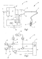
- FIG. 1 There is illustrated an apparatus 10 for coagulating biological tissue 11, which may be, for example, a hollow vessel or any other biological tissue.
- the tissue 11 is a blood vessel which is to be closed by coagulation, ie a fusion of the opposing walls of the vessel is to be carried out.
- two electrodes 12, 13 which grasp the fabric 11 between each other and also stress it mechanically, for example by compressing it.
- the electrodes 12, 13 may be the branches of a bipolar fusion instrument.
- the electrodes 12, 13 are connected via a line 14 to a feeding device 15.
- the line 14 has, for example, two cores 16, 17, to which high-frequency current is supplied or can be supplied by the device 15.
- the device 15 has a source 18, for example in the form of a controllable HF generator 19. This can be supplied via a power supply 20 and a power supply 21 via a supply network with operating voltage.
- the HF generator 19 and / or the power supply 20 are designed to be controllable.
- a control unit 22 is connected, which in particular controls or regulates the output of electrical power by the HF generator 19.
- the control unit 22 includes a monitoring unit 23, which detects the electrical quantities of the electrodes 12, 13 supplied electrical energy.
- the monitoring unit 23 is set up, at least temporarily to detect and integrate the electrical power supplied to the electrodes 12, 13 to determine the energy delivered in a time interval.
- the monitoring unit 23 may have a voltage block 24 for monitoring the voltage applied to the terminals 12, 13.
- the monitoring unit 23 may have a current block 25 for determining the size of the current supplied to the electrodes 12, 13.
- the control unit 22 may further comprise a module 26 for determining the end of a first phase of operation I, the module receiving at least one output signal of the voltage block 24 or the current block 25 or a signal derived from its output signals for operating phase end detection.
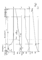
- the control unit 22 is in FIG. 2 schematically simplified and illustrated only in part.
- the current block 25 the current I IST flowing through the tissue 11 is detected.
- the voltage block 24 the voltage applied to the fabric 11 actual voltage U IST is detected. From both variables, the actual power P IST supplied to the fabric 11 is calculated, at least temporarily.
- the power P IST may be the detected active power or the apparent power supplied to the electrodes 12, 13.
- a corresponding block 27 is used for calculating or otherwise determining the power P IST .
- the control unit 22 may also have a current specification block 28, which specifies a current I SOLL depending on the time and / or situation.
- a voltage specification block 29 may be provided to specify a desired voltage U SOLL .
- the current specification block 28 and the voltage specification block 29 may be controlled by an impedance block 30, which determines a desired relationship between the voltage U SOLL and the current I SOLL time and or situation-dependent, for example, a desired tissue resistance Set R G or a desired time course of the same.
- the target actual deviations for the current I IST and the voltage U IST are respectively formed and fed to a processing module 33.
- the latter controls the generator 19.
- the processing module 33 also includes the module 26 for detecting various phases of operation.
- This module 26 may receive (via non-illustrated signal paths) at least the actual current I IST and / or the actual U actual voltage or a value derived from these quantities as an input variable.
- an energy block 34 for determining the power supplied to the fabric 11. This integrates the measured power P IST over a period of time predetermined by the processing module 33 and supplies the integral to the processing block 33.
- blocks 27 to 32 and 34 may also be part of the processing module 33.
- the operating phase I begins first with a partial phase Ia.
- the current I IST is controlled to a desired current value of 4 A, for example. It can be guided from an initial value, such as 1 A within a period t 1a to the target value of, for example, 4 A. This can be done in a linear ramp: the time for this can be between 200 ms and 2 s.
- the effective value of the current is preferably taken as the measured variable.
- the tissue resistance R G drops from an initial value to a minimum value of, for example, 2 ohms to 40 ohms.
- the voltage U IST increases during the period t 1a .
- the current I is increased during this time, preferably in the form of a ramp.
- the peak voltage between the electrodes 12, 13 can be measured as the measured value for the voltage U IST .
- the current I IST is then kept constant at a value i 1b during a further partial phase Ib.
- the control unit 22 operates as a current control circuit for keeping constant the value i 1b .
- the energy block 34 integrates the power determined by the block 27 and supplies the determined value of the energy E 1 to the processing module 33 at the end of the operating phase I.
- the start and end of the operating phase I are determined by the times t 0 and t 1 marked.
- the time t 1 is determined by the processing module 33 according to one of the above criteria.
- the operating phase II With the end of the operating phase I begins the operating phase II. This starts preferably with the same current I IST , with the operating phase I has ended. In addition, it preferably starts with the same voltage U actual , with which the first operating phase I has ended.
- the generator 19 is operated impedance controlled in the operating phase II, ie the control unit 22 forms a regulator for the tissue impedance.
- a desired temporal impedance increase A is set. In FIG. 3 For example , the impedance increase A as a desired dashed line over time is illustrated as R Gsoll .
- the impedance increase A may be 50 to 200, preferably 100 ohms per second.
- the targeted slow increase of the impedance causes a stabilization of the evaporation of the tissue fluid.
- the operating phase II is terminated when the duration t 2 has elapsed.
- the time t max is the maximum duration of treatment.
- t min is a fixed value of, for example, 5.4 seconds, or the value resulting from calculating the parenthesis, whichever is less.
- phase III of operations will commence.
- the voltage U IST is controlled to the value U 3 for a time t 3 constant.
- the control unit 22 operates here as a voltage regulator circuit.
- the achievement of the maximum duration t 3 of the operating phase III can be detected.
- a device 10 for tissue coagulation, in particular fusion has an electrical source 18 which is connected or connectable to electrodes 12, 13 for the action of current on biological tissue 11.
- a controller 22 controls the source 18 during phases I and II of tissue fusion.
- Operating phases I, II and III of the device 10 correspond to these phases I and II.
- a monitoring unit 23 detects the energy E 1 applied to the tissue 11.
- the control unit 22 controls the source 18 in the subsequent operating phases II and III on the basis of the detected energy E 1 .
- Such a device proves to be particularly reliable and robust in use.
Abstract
Eine Einrichtung (10) zur Gewebekoagulation, insbesondere Fusion, weist eine elektrische Quelle (18) auf, die mit Elektroden (12, 13) zur Stromeinwirkung auf biologisches Gewebe (11) verbunden oder verbindbar ist. Eine Steuereinheit (22) steuert die Quelle (18) während der Phasen I und II der Gewebefusion. Diesen Phasen I und II entsprechen Betriebsphasen I, II und III der Einrichtung (10). Während der Betriebsphase I erfasst eine Überwachungseinheit (23), die in das Gewebe (11) applizierte Energie E 1 . Die Steuereinheit (22) steuert die Quelle (18) in den nachfolgenden Betriebsphasen II und III anhand der erfassten Energie E 1 . Eine solche Einrichtung erweist sich als besonders zuverlässig und im Einsatz robust.A device (10) for tissue coagulation, in particular fusion, has an electrical source (18) which is connected or connectable to electrodes (12, 13) for the action of current on biological tissue (11). A controller (22) controls the source (18) during phases I and II of tissue fusion. These phases I and II correspond to operating phases I, II and III of the device (10). During the operating phase I, a monitoring unit (23) detects the energy E 1 applied to the tissue (11). The control unit (22) controls the source (18) in the subsequent operating phases II and III on the basis of the detected energy E 1. Such a device proves to be particularly reliable and robust in use.
Description
Die Erfindung betrifft eine Einrichtung zur Gewebekoagulation, insbesondere zur Gewebefusion.The invention relates to a device for tissue coagulation, in particular for tissue fusion.
Es sind verschiedene elektrochirurgische Verfahren in Gebrauch, deren Effekt auf einer kontrollierten Denaturierung biologischen Gewebes beruht.There are various electrosurgical procedures in use, the effect of which is based on a controlled denaturation of biological tissue.
Beispielsweise offenbart die
Auch die
Ebenfalls anhand der initialen Gewebeimpedanz wird die Thermofusion gemäß
Die
Die
Die
Auch die
Auch die
Der lokale Zustand von Gewebe wird durch die lokale spezifische Gewebeimpedanz charakterisiert. Die Erfassung der Impedanz zwischen zwei Elektroden liefert zwar einen Anhaltspunkt für den Zustand und somit den Behandlungsfortschritt des Gewebes insgesamt, wobei jedoch die lokale spezifische Gewebeimpedanz nicht erfasst wird. Dies kann zu Fehlschlüssen bei inhomogenem Gewebe führen.The local state of tissue is characterized by the local specific tissue impedance. Although the detection of the impedance between two electrodes provides an indication of the condition and thus the treatment progress of the tissue as a whole, but the local specific tissue impedance is not detected. This can lead to erroneous results in inhomogeneous tissue.
Es ist Aufgabe der Erfindung, eine alternative Einrichtung zur Gewebekoagulation zu schaffen.It is an object of the invention to provide an alternative device for tissue coagulation.
Diese Aufgabe wird mit der Einrichtung nach Anspruch 1 gelöst:This object is achieved with the device according to claim 1:
Die erfindungsgemäße Einrichtung dient zur Gewebekoagulation sowie bedarfsweise auch zur Gewebefusion. Dazu ist eine elektrische Quelle mit Elektroden zur Stromeinwirkung auf biologisches Gewebe verbunden oder verbindbar. Die elektrische Quelle kann eine Quelle für Gleichstrom oder Wechselstrom, vorzugsweise HF-Strom, sein. Die Quelle ist vorzugsweise steuerbar ausgebildet, um die Größe des abgegebenen Stroms und/oder der abgegebenen Spannung steuern zu können. Sie ist dazu an eine Steuereinheit angeschlossen. Diese enthält eine Überwachungseinheit, die mit der Quelle verbunden ist. Insbesondere ist die Überwachungseinheit mit dem Ausgang der Quelle verbunden, an den auch die Elektroden angeschlossen sind. Alternativ kann die Überwachungseinheit mit den Elektroden verbunden sein. Die Überwachungseinheit erfasst somit mindestens eine elektrische Größe, die die Energie kennzeichnet, die während einer ersten Betriebsphase von der Quelle an die Elektroden und somit von den Elektroden an das Gewebe abgegeben worden ist. Die erste Betriebsphase entspricht der Phase I der Gewebekoagulation, während derer der Gewebewiderstand abnimmt und ein Minimum durchläuft.The inventive device is used for tissue coagulation and, if necessary, for tissue fusion. For this purpose, an electrical source is connected or connectable to electrodes for the action of current on biological tissue. The electrical source may be a source of DC or AC, preferably RF. The source is preferably designed to be controllable in order to be able to control the magnitude of the emitted current and / or the delivered voltage. It is connected to a control unit. This contains a monitoring unit that works with the source connected is. In particular, the monitoring unit is connected to the output of the source, to which the electrodes are also connected. Alternatively, the monitoring unit may be connected to the electrodes. The monitoring unit thus detects at least one electrical quantity that characterizes the energy that has been emitted from the source to the electrodes and thus from the electrodes to the tissue during a first operating phase. The first phase of operation corresponds to phase I of tissue coagulation, during which the tissue resistance decreases and passes through a minimum.
Zum Beispiel kann die Überwachungseinheit die aktuelle Leistung erfassen und diese während der ersten Betriebsphase aufintegrieren, um die abgegebene Energie zu ermitteln. Insbesondere ist es vorteilhaft, wenn die Überwachungseinheit die von den Elektroden abgegebene Wirkleistung erfasst. Durch Aufintegrieren wird daraus die Wirkenergie ermittelt, die im Gewebe thermisch umgesetzt worden ist. Die in der ersten Betriebsphase in das Gewebe eingebrachte Energie wird zur Steuerung der zweiten Betriebsphase genutzt. Diese entspricht der Phase II der Gewebekoagulation, während derer der Gewebewiderstand zunimmt und das Gewebe durch verkochen von Gewebeflüssigkeit trocknet.For example, the monitoring unit may detect the current power and integrate it during the first phase of operation to determine the energy output. In particular, it is advantageous if the monitoring unit detects the active power output by the electrodes. By integrating the active energy is determined, which has been thermally converted in the tissue. The energy introduced into the tissue during the first phase of operation is used to control the second phase of operation. This corresponds to phase II of tissue coagulation, during which tissue resistance increases and the tissue dries by boiling down tissue fluid.
Alternativ kann die Scheinleistung erfasst werden, die jedoch Blindleistungsanteile enthält. Sind diese bekannt oder konstant, kann auch die Scheinleistung und damit die insgesamt abgegebene Scheinenergie zur Steuerung der zweiten Betriebsphase genutzt werden.Alternatively, the apparent power may be detected but includes reactive power components. If these are known or constant, the apparent power and thus the total apparent energy output can also be used to control the second operating phase.
Die Steuereinheit steuert die Quelle in der zweiten Betriebsphase anhand der während der ersten Betriebsphase ermittelten Energie (Wirkenergie oder Scheinenergie). Dadurch wird sichergestellt, dass die in der zweiten Betriebsphase applizierte Energiemenge an die Größe des von den Elektroden erfassten und beeinflussten Gewebeareals angepasst ist. Die in der ersten Phase I geöffneten Zellen setzen Gewebeflüssigkeit frei. In der zweiten Phase II wird diese unter Auftrocknung des Gewebes verdampft. Durch Erfassung der in der ersten Betriebsphase applizierten Energie steht ein Parameter zur Verfügung, anhand dessen die Phase II so gesteuert werden kann, dass das gesamte in Phase I elektrochirurgisch beeinflusste Gewebe gleichmäßig koaguliert wird.The control unit controls the source in the second operating phase based on the determined during the first phase of operation energy (active energy or apparent energy). This will ensure that in the second phase of operation applied amount of energy is adapted to the size of the detected and influenced by the electrodes tissue area. The cells opened in the first phase I release tissue fluid. In the second phase II, this is evaporated while drying the tissue. By detecting the energy applied in the first phase of operation, a parameter is available by means of which phase II can be controlled such that the entire tissue electrosurgically influenced in phase I is uniformly coagulated.
Es ist zweckmäßig, wenn die Steuereinheit die Quelle in der ersten Betriebsphase I mit geregeltem Strom betreibt. Dabei ist es sowohl möglich, zu Beginn einen zeitlich ansteigenden Strom vorzugeben, wie auch im weiteren Fortschritt der Betriebsphase I einen konstanten Strom. Dadurch tritt eine Gewebeerwärmung und eine Elektrodenerwärmung auf. Durch thermische Gewebedenaturierung kommt es zu einer Verminderung der Gewebeimpedanz, die zum Beispiel zwischen 2 Ohm und 40 Ohm liegen kann. Durch Dampfbildung und beginnende Austrocknung des Gewebes kann die Impedanz während der Betriebsphase I wieder ansteigen, bis das Ende der Phase I erkannt wird. Dazu können verschiedene Erkennungskriterien genutzt werden. Zum Beispiel kann das Verhältnis zwischen Spannung und Strom an der Quelle und somit die Gewebeimpedanz über einen Grenzwert hinaus ansteigen. Alternativ kann als Erkennungskriterium genutzt werden, wenn das Verhältnis zwischen Spannung und Strom an der Quelle, d.h. die Gewebeimpedanz, ein Minimum durchläuft. Weiter alternativ kann als Erkennungskriterium genutzt werden, dass die Spannung an der Quelle einen Grenzwert übersteigt. Weiter alternativ kann als Erkennungskriterium genutzt werden, dass der von der Quelle konstant zu haltende Strom unter einen Schwellwert abfällt, weil beispielsweise die von der Steuereinheit und der Quelle gebildete Stromregelschaltung ihren Regelbereich verlässt. Dies kann geschehen, wenn die Quelle ihre Maximalspannung oder eine sonstige Spannungsgrenze erreicht hat. Auch kann alternativ die Geschwindigkeit der Änderung des Gewebewiderstands (Verhältnis zwischen Spannung und Strom an der Quelle) als Abschaltkriterium genutzt werden, zum Beispiel indem für die Anstiegsgeschwindigkeit der Gewebeimpedanz eine Grenze festgelegt und deren Erreichen überwacht wird.It is expedient if the control unit operates the source in the first operating phase I with controlled current. It is both possible to initially specify a time-increasing current, as well as in the further progress of the operating phase I a constant current. As a result, tissue heating and electrode heating occur. Thermal tissue denaturation reduces tissue impedance, which may be between 2 ohms and 40 ohms, for example. As a result of the formation of steam and the drying out of the fabric, the impedance can rise again during the operating phase I until the end of the phase I is detected. For this purpose, different recognition criteria can be used. For example, the voltage-to-current ratio at the source, and thus the tissue impedance, may increase above a threshold. Alternatively, it can be used as a recognition criterion when the voltage-to-current ratio at the source, ie, the tissue impedance, goes through a minimum. Further alternatively, it can be used as a recognition criterion that the voltage at the source exceeds a limit value. As a further alternative, it can be used as a recognition criterion that the current to be kept constant by the source drops below a threshold value, because, for example, the current control circuit formed by the control unit and the source leaves its control range. This can happen when the source has reached its maximum voltage or other voltage limit. Alternatively, the rate of change of tissue resistance (voltage-to-current ratio at the source) may alternatively be used as a turn-off criterion, for example by setting a limit on the rate of rise of the tissue impedance and monitoring its attainment.
Jedenfalls wird am Ende der Betriebsphase I die bislang applizierte Energie gespeichert. Der Fortgang der weiteren Steuerung der Betriebsphase II wird aus diesem Energiewert abgeleitet. Insbesondere kann die Dauer der Betriebsphase II entsprechend dem Energiewert aus der Betriebsphase I festgelegt werden. Auch kann das Abschaltkriterium, d.h. das Ende einer sich anschließenden Betriebsphase III, anhand des in der ersten Betriebsphase ermittelten Energiewerts festgelegt werden. Somit sind die Steuerungsparameter, d.h. die Dauer der Betriebsphase II und das Abschaltkriterium, d.h. das Ende der Betriebsphase III, Funktionen der in der Betriebsphase 1 gemessenen Energie. Vorzugsweise erfolgt der Übergang von der Betriebsphase I zur Betriebsphase II stetig, d.h. ohne sprungartige Änderung des an das biologische Gewebe gelieferten Stroms und/oder ohne sprungartige Änderung der an das Gewebe angelegten Spannung und/oder ohne sprungartige Änderung der an das Gewebe abgegebenen Leistung.In any case, the previously applied energy is stored at the end of the operating phase I. The progress of the further control of the operating phase II is derived from this energy value. In particular, the duration of the operating phase II can be determined according to the energy value from the operating phase I. Also, the shutdown criterion, i. the end of a subsequent phase of operation III, be determined on the basis of the energy value determined in the first phase of operation. Thus, the control parameters, i. the duration of the operating phase II and the switch-off criterion, i. the end of the operating phase III, functions of the energy measured in the
In der Betriebsphase II betreibt die Steuereinheit die Quelle vorzugsweise impedanzgeregelt als Sollwert des Impedanzanstiegs. Für die Gewebeimpedanz empfiehlt sich ein Wert oberhalb 100 Ohm pro Sekunde. Die gezielte langsame Erhöhung der Impedanz bewirkt eine Verstetigung der Verdampfung von Gewebeflüssigkeit. Die Dampfbildung erfolgt gleichmäßig und räumlich verteilt. Der gewünschte zeitliche Verlauf der Impedanz kann einen konstanten Anstieg oder auch einen variablen Anstieg haben. Vorzugsweise legt die Steuereinheit die zeitliche Länge der Betriebsphase II in Abhängigkeit von der in der ersten Betriebsphase erfassten Energie fest. Die zweite Betriebsphase wird beendet, wenn die Zeit t2 verstrichen ist. Es schließt sich (optional) die dritte Betriebsphase III an. In dieser wird vorzugsweise an das biologische Gewebe eine konstante Spannung appliziert.In the operating phase II, the control unit preferably operates the source with impedance control as the nominal value of the impedance increase. For tissue impedance, a value above 100 ohms per second is recommended. The targeted slow increase in impedance causes a stabilization of the evaporation of tissue fluid. The formation of steam takes place evenly and spatially. The desired temporal The course of the impedance can have a constant increase or a variable increase. The control unit preferably determines the length of time of the operating phase II as a function of the energy detected in the first operating phase. The second phase of operation is terminated when the time t 2 has elapsed. It joins (optional) the third phase III operation. In this, a constant tension is preferably applied to the biological tissue.
Das Ende der dritten Betriebsphase III kann dadurch festgelegt sein, dass die minimale Behandlungszeit verstrichen ist und eine Energie Eges erreicht worden ist. Die Energie Eges kann in Abhängigkeit von der in der ersten Betriebsphase erfassten Energie E1 festgelegt sein. Die minimale Behandlungszeit tmin kann ebenfalls von der Energie E1 bestimmt werden. Alternativ kann die Betriebsphase III beendet werden, wenn die maximale Behandlungszeit verstrichen ist. Diese kann wiederum in Abhängigkeit von der minimalen Behandlungszeit und somit ebenfalls in Abhängigkeit von der in der ersten Betriebsphase erfassten Energie E1 festgelegt werden. Weitere Abschaltkriterien in die jeweils in Abhängigkeit von der Energie E1 stehen, können festgelegt werden.The end of the third operating phase III can be determined by the fact that the minimum treatment time has elapsed and an energy E ges has been reached. The energy E tot may be determined as a function of the energy E 1 detected in the first operating phase. The minimum treatment time t min can also be determined by the energy E 1 . Alternatively, the operation phase III may be terminated when the maximum treatment time has elapsed. This can in turn be determined as a function of the minimum treatment time and thus likewise as a function of the energy E 1 detected in the first operating phase. Further shutdown criteria, each of which depends on the energy E 1 , can be defined.
Im Laufe der Behandlung kann es vorkommen, dass sich Behandlungsparameter ändern. Beispielsweise kann durch versehentliches zeitweiliges Lockern der Elektroden von dem biologischen Gewebe (Öffnen von Fusionsklemmen) nachdringende Gewebeflüssigkeit, wie Blut oder Spülflüssigkeit, den Prozess beeinflussen. Somit kann es notwendig werden, dass eine größere Energiemenge und längere Applikationszeit notwendig wird als ursprünglich aus der Energie E1 abgeleitet wurde. Um in solchen Fällen eine ordnungsgemäße Fusion zu erreichen, kann während der zweiten (und/oder dritten) Betriebsphase die aktuelle Leistung beobachtet werden. Sofern die Leistung innerhalb eines Beobachtungszeitintervalls ein vorgegebenes Fenster aus minimaler Leistung Pmin und maximaler Leistung Pmax für einen nicht vernachlässigbar kurzen Zeitraum verlässt, kann die Applikationszeit, d.h. die Zeiten t2 und t3, sowie Rechenparameter tmin und/oder tmaX entsprechend verlängert werden.In the course of treatment, treatment parameters may change. For example, by inadvertently loosening the electrodes temporarily from the biological tissue (opening fusion clips), penetrating tissue fluid, such as blood or irrigation fluid, may affect the process. Thus, it may be necessary that a larger amount of energy and longer application time is required than was originally derived from the energy E 1 . In order to achieve a proper merger in such cases, during the second (and / or third) operating phase the current performance can be observed. If the power within a monitoring time interval leaves a predetermined window of minimum power P min and maximum power P max for a not insignificantly short period of time, the application time, ie the times t 2 and t 3 , as well as the calculation parameters t min and / or t maX, may be appropriate be extended.
Weitere Einzelheiten von Ausführungsformen der Erfindung ergeben sich aus Ansprüchen, aus der Zeichnung und/ oder aus der nachfolgenden Beschreibung eines veranschaulichenden Beispiels. Es zeigen:
-
Figur 1 -
Figur 2 eine Steuereinheit für dieEinrichtung nach Figur 1 , in ausschnittsweiser schematisierter Blockdarstellung und -
Figur 3 Zeitdiagramme zur Erläuterung der Funktion der Steuereinheit.
-
FIG. 1 the device according to the invention, in a schematic representation. -
FIG. 2 a control unit for the device according toFIG. 1 , in a fragmentary schematic block diagram and -
FIG. 3 Timing diagrams to explain the function of the control unit.
In
Die Elektroden 12, 13 sind über eine Leitung 14 mit einem speisenden Gerät 15 verbunden. Die Leitung 14 weist dazu zum Beispiel zwei Adern 16, 17 auf, denen von dem Gerät 15 hochfrequenter Strom zugeführt wird oder zugeführt werden kann.The
Dazu weist das Gerät 15 eine Quelle 18, zum Beispiel in Gestalt eines steuerbaren HF-Generators 19, auf. Dieser kann über ein Netzteil 20 und einen Netzanschluss 21 über ein Versorgungsnetz mit Betriebsspannung versorgt sein.For this purpose, the
Der HF-Generator 19 und/oder das Netzteil 20 sind steuerbar ausgebildet. An ihren entsprechenden Steuereingänge ist, wie Pfeile veranschaulichen, eine Steuereinheit 22 angeschlossen, die insbesondere die Abgabe elektrischer Leistung durch den HF-Generator 19 steuert oder regelt. Dazu enthält die Steuereinheit 22 eine Überwachungseinheit 23, die die elektrischen Größen der den Elektroden 12, 13 zugeführten Elektroenergie erfasst. Insbesondere ist die Überwachungseinheit 23 dazu eingerichtet, zumindest zeitweilig die den Elektroden 12, 13 zugeführte elektrische Leistung zu erfassen und aufzuintegrieren, um die in einem Zeitintervall gelieferte Energie zu bestimmen. Die Überwachungseinheit 23 kann einen Spannungsblock 24 zur Überwachung der an den Klemmen 12, 13 liegenden Spannung aufweisen. Außerdem kann die Überwachungseinheit 23 einen Stromblock 25 zur Bestimmung der Größe des zu den Elektroden 12, 13 gelieferten Stroms aufweisen. Die Steuereinheit 22 kann außerdem ein Modul 26 zur Festlegung des Endes einer ersten Betriebsphase I aufweisen, wobei das Modul wenigstens ein Ausgangssignal des Spannungsblocks 24 oder des Stromblocks 25 oder ein aus deren Ausgangssignalen abgeleitetes Signal zur Betriebsphasenenderkennung erhält.The
Die Steuereinheit 22 ist in
Die Steuereinheit 22 kann außerdem einen Stromvorgabeblock 28 aufweisen, der zeit- und/oder situationsabhängig einen Strom ISOLL vorgibt. Ebenso kann ein Spannungsvorgabeblock 29 vorgesehen sein, um eine gewünschte Spannung USOLL vorzugeben. Der Stromvorgabeblock 28 und der Spannungsvorgabeblock 29 können von einem Impedanzblock 30 gesteuert sein, der ein gewünschtes Verhältnis zwischen der Spannung USOLL und dem Strom ISOLL zeit- und oder situationsabhängig festlegt, beispielsweise um einen gewünschten Gewebewiderstand RG oder einen gewünschten zeitlichen Verlauf desselben festzulegen.The
In entsprechenden Differenzbildungsblöcken 31, 32 werden jeweils die Soll-Ist-Abweichungen für den Strom IIST und die Spannung UIST gebildet und einem Verarbeitungsmodul 33 zugeführt. Letzteres steuert den Generator 19.In respective subtraction blocks 31, 32, the target actual deviations for the current I IST and the voltage U IST are respectively formed and fed to a
Das Verarbeitungsmodul 33 enthält außerdem das Modul 26 zur Erkennung verschiedener Betriebsphasen. Dieses Modul 26 kann (über nicht veranschaulichte Signalwege) wenigstens den tatsächlichen Strom IIST und/oder die tatsächliche UIST Spannung oder einen aus diesen Größen abgeleiteten Wert als Eingangsgröße erhalten.The
An den Block 27 zur Leistungsermittlung ist ein Energieblock 34 zur Bestimmung der an das Gewebe 11 gelieferten Energie angeschlossen. Dieser integriert die gemessene Leistung PIST über einen von dem Verarbeitungsmodul 33 vorgegebenen Zeitraum auf und liefert das Integral an den Verarbeitungsblock 33.To the
Es wird darauf hingewiesen, dass die Blöcke 27 bis 32 sowie 34 auch Teil des Verarbeitungsmoduls 33 sein können.It should be noted that the
Der weitere Aufbau des Geräts 15 und insbesondere seiner Steuereinheit 22 ergibt sich aus der nachfolgenden Beschreibung von deren Zeitverhalten:The further construction of the
Es wird davon ausgegangen, dass zunächst zwischen den Elektroden 12, 13 lebendes, nicht denaturiertes Gewebe 11 gefasst ist. Das Gerät 15 erhält nun an seinem Aktivierungseingang 35 das Signal zur Koagulation und gegebenenfalls Fusion des biologischen Gewebes 11. Dies entspricht dem in
Während der ersten Teilphase Ia oder während der zweiten Teilphase Ib durchläuft der Gewebewiderstand RG ein Minimum, um dann wieder anzusteigen. Wird das Gewebewiderstands-Minimum schon in der ersten Teilphase Ia erreicht, kann die Teilphase Ib übersprungen und direkt in die Betriebsphase II übergegangen werden. Dabei kann unter Umständen die Leistungsgrenze des Generators 19 erreicht werden, so dass es der Stromregelschaltung nicht mehr gelingt, den Strom IIST mit dem gewünschten Strom ISOLL in Übereinstimmung zu bringen. Der Strom fällt somit gegen Ende der Betriebsphase I ab. Je nach Ausführungsform kann dieser Abfall des Stroms i1b oder auch der von dem Differenzbildungsblock 31 gebildete Stromdifferenzwert (ISOLL - IIST) als Kennzeichen für das Ende der Betriebsphase I genutzt werden. Es ist auch möglich, dass die Steuereinheit 22 die Gewebeimpedanz RG als Quotient aus UIST und IIST ermittelt und das Ende der Betriebsphase I feststellt, wenn der Gewebewiderstand eine gegebene Schwelle überschreitet. Alternativ kann auch die Anstiegsgeschwindigkeit für den Gewebewiderstand RG überwacht werden. Demnach können kumulativ oder alternativ von der Steuereinheit 22 folgende Kriterien zur Erkennung der Betriebsphase I genutzt werden:
- Detektion des Durchlaufens des Minimums der Gewebeimpedanz oder des Gewebewiderstands dR/dt = 0)
- Unterschreiten eines Schwellwerts des Stroms IIST, zum Beispiel 0,5 * i1b
- Überschreiten eines Schwellwert der Gewebeimpedanz, zum Beispiel von 80 Ohm
- Überschreiten eines Schwellwerts der Anstiegsgeschwindigkeit der Gewebeimpedanz (dR/dt)
- Detection of passage of the minimum of tissue impedance or tissue resistance dR / dt = 0)
- Falling below a threshold value of the current I IST , for example, 0.5 * i 1b
- Exceeding a tissue impedance threshold, for example 80 ohms
- Exceeding a Threshold Rate of Tissue Impedance Rise Rate (dR / dt)
Während der gesamten Betriebsphase I integriert der Energieblock 34 die von dem Block 27 ermittelte Leistung und liefert am Ende der Betriebsphase I den ermittelten Wert der Energie E1 an das Verarbeitungsmodul 33. Anfang und Ende der Betriebsphase I werden durch die Zeitpunkte t0 und t1 markiert. Der Zeitpunkt t1 wird von dem Verarbeitungsmodul 33 nach einem der oben genannten Kriterien bestimmt.During the entire operating phase I, the
Mit dem Ende der Betriebsphase I beginnt die Betriebsphase II. Diese beginnt vorzugsweise mit dem gleichen Strom IIST, mit der die Betriebsphase I geendet hat. Außerdem beginnt sie vorzugsweise mit der gleichen Spannung UIST, mit der die erste Betriebsphase I geendet hat. Für die Betriebsphase II werden nun Betriebskriterien anhand der in der Betriebsphase I ermittelten applizierten Energie E1 festgelegt. Vorzugsweise wird der Generator 19 in der Betriebsphase II impedanzgeregelt betrieben, d.h. die Steuereinheit 22 bildet einen Regler für die Gewebeimpedanz. Für die Gewebeimpedanz wird ein gewünschter zeitlicher Impedanzanstieg A festgelegt. In
Der Impedanzanstieg A kann 50 bis 200, vorzugsweise 100 Ohm pro Sekunde betragen. Die gezielte langsame Erhöhung der Impedanz bewirkt eine Verstetigung der Verdampfung der Gewebeflüssigkeit.The impedance increase A may be 50 to 200, preferably 100 ohms per second. The targeted slow increase of the impedance causes a stabilization of the evaporation of the tissue fluid.
Die Betriebsphase II wird beendet, wenn die Dauer t2 verstrichen ist. Die Dauer t2 kann auf folgende Weise aus der Energie E1 ermittelt werden: 
Die Zeit tmaX ist dabei die maximale Behandlungsdauer. Die maximale Behandlungsdauer tmax lässt sich aus der minimalen Behandlungsdauer errechnen, indem ein konstanter vorgegeben Summand addiert wird, zum Beispiel: 
Die minimale Behandlungsdauer tmin lässt sich beispielsweise nach folgender Beziehung aus der Energie E1 bestimmen: 
Danach ist tmin ein festgelegter Wert von zum Beispiel 5,4 s oder der sich durch Ausrechnen der runden Klammer ergebende Wert, je nachdem, welcher Wert geringer ist.Thereafter, t min is a fixed value of, for example, 5.4 seconds, or the value resulting from calculating the parenthesis, whichever is less.
Mit Ende der Betriebsphase II wird die Betriebsphase III begonnen. In dieser wird die Spannung UIST auf den Wert U3 für eine Zeitspanne t3 konstant geregelt. Die Steuereinheit 22 arbeitet hier als Spannungsreglerschaltung.At the end of phase II, phase III of operations will commence. In this, the voltage U IST is controlled to the value U 3 for a time t 3 constant. The
Während der Betriebsphasen II und III, die der Phase II der Gewebekoagulation entsprechen, wird die Leistung weiter aufintegriert. Erreicht dieser Wert den Gesamthöchstwert Eges, wird die Behandlung beendet. Der Gesamthöchstwert Eges kann nach verschiedenen empirisch gewonnenen Formeln in Abhängigkeit von der Energie E1 ermittelt werden, beispielsweise folgendermaßen: 
Alternativ kann das Erreichen der maximalen Dauer t3 der Betriebsphase III erkannt werden. Diese Dauer t3 kann zum Beispiel nach: 
berechnet werden.Alternatively, the achievement of the maximum duration t 3 of the operating phase III can be detected. This duration t 3 can be, for example, after:
be calculated.
Zur Vermeidung von Fehlbehandlungen durch unvorhergesehene Änderungen der Behandlungsparameter, beispielsweise durch versehentliches Öffnen der Fusionsklemmen, kann zusätzlich überwacht werden, ob innerhalb eines Beobachtungszeitintervalls, beispielsweise während der Betriebshase II und/oder III, die tatsächliche Leistung ein Leistungsfenster aus Pmin und Pmax verlässt. Falls dies für längere Zeit der Fall ist, kann die Applikationszeit verlängert werden.In order to avoid maltreatment due to unforeseen changes in the treatment parameters, for example by accidentally opening the fusion clamps, it is additionally possible to monitor whether within an observation time interval, For example, during operational phase II and / or III, the actual power leaves a power window of P min and P max . If this is the case for a longer time, the application time can be extended.
Eine Einrichtung 10 zur Gewebekoagulation, insbesondere Fusion, weist eine elektrische Quelle 18 auf, die mit Elektroden 12, 13 zur Stromeinwirkung auf biologisches Gewebe 11 verbunden oder verbindbar ist. Eine Steuereinheit 22 steuert die Quelle 18 während der Phasen I und II der Gewebefusion. Diesen Phasen I und II entsprechen Betriebsphasen I, II und III der Einrichtung 10. Während der Betriebsphase I erfasst eine Überwachungseinheit 23, die in das Gewebe 11 applizierte Energie E1. Die Steuereinheit 22 steuert die Quelle 18 in den nachfolgenden Betriebsphasen II und III anhand der erfassten Energie E1. Eine solche Einrichtung erweist sich als besonders zuverlässig und im Einsatz robust.A
- 1010
- EinrichtungFacility
- 1111
- biologisches Gewebebiological tissue
- 12, 1312, 13
- Elektrodenelectrodes
- 1414
- Leitungmanagement
- 1515
- Gerätdevice
- 16, 1716, 17
- Adernveins
- 1818
- Quellesource
- 1919
- HF-GeneratorRF generator
- 2020
- Netzteilpower adapter
- 2121
- Netzanschlussmains connection
- 2222
- Steuereinheitcontrol unit
- 2323
- Überwachungseinheitmonitoring unit
- 2424
- Spannungsblockvoltage block
- 2525
- Stromblockpower block
- 2626
- Modul zur Erkennung von BetriebsphasenModule for detecting operating phases
- UIST U IS
- Spannung (z.B. Spitzenwert)Voltage (e.g., peak)
- IIST I IS
- Strom (z.B. Effektivwert)Current (e.g., rms value)
- PIST P IS
- Leistungpower
- 2727
- Block zur LeistungsermittlungBlock for performance determination
- 2828
- StromvorgabeblockCurrent instruction block
- ISOLL I SHOULD
- gewünschter Stromdesired current
- 2929
- SpannungsvorgabeblockVoltage setting block
- USOLL U SHOULD
- gewünschte Spannungdesired voltage
- 3030
- Impedanzblockimpedance block
- RG R G
- Gewebewiderstandtissue resistance
- 31, 3231, 32
- DifferenzbildungsblöckeDifference blocks
- 3333
- Verarbeitungsmodulprocessing module
- 3434
- Energieblockenergy block
- 3535
- Aktivierungseingangenable input
- t0 t 0
- Aktivierungsbeginnactivation beginning
- II
- erste Betriebsphasefirst operating phase
- IaIa
- Teilphasepartial phase
- t1a t 1a
- Dauer der ersten TeilphaseDuration of the first subphase
- Ibib
- Teilphasepartial phase
- i1a i 1a
- Wert des Stroms IIST in der Teilphase IaValue of the current I IS in the subphase Ia
- i1b i 1b
- Wert des Stroms IIST in der Teilphase IbValue of the current I IS in the subphase Ib
- t1 t 1
- Dauer der Betriebsphase IDuration of the operating phase I
- E1 E 1
-
in Phase I in das Gewebe 11 eingetragene Energiein phase I entered into the
tissue 11 energy - AA
- Impedanzanstiegimpedance rise
- RGsoll R Goll
- gewünschter Impedanzverlaufdesired impedance curve
- RGist R Gist
- tatsächlicher Impedanzverlaufactual impedance curve
- t2 t 2
- Dauer der Betriebsphase IIDuration of the operating phase II
- tmaX t maX
- maximale Behandlungsdauermaximum duration of treatment
- tmin min
- minimale Behandlungsdauerminimal treatment duration
- Eges E ges
- Gesamthöchstwert der EnergieTotal maximum value of energy
- t3 t 3
- Dauer der Betriebsphase IIIDuration of the operating phase III
- tges t tot
- gesamte Dauer der Behandlungentire duration of treatment
- RGmax R Gmax
- Grenzwert für Gewebewiderstand in der Betriebsphase IThreshold for tissue resistance in the operational phase I
- MM
- Minimum des Gewebewiderstands in der Betriebsphase IMinimum of tissue resistance in the operational phase I
- U3 U 3
- Spannung in der Betriebsphase IIIVoltage in the operating phase III
- Pmax, Pmin P max , P min
-
legen Leistungsfenster für die Leistung P der Quelle 18 in den Betriebsphasen II und/oder III festdefine power windows for the power P of the
source 18 in the operating phases II and / or III
Claims (15)
zur Gewebefusion,
mit einer elektrischen Quelle (18), die mit Elektroden (12, 13) zur Stromeinwirkung auf biologisches Gewebe (11) verbindbar ist,
mit einer Überwachungseinheit (23), die an die Quelle (18) angeschlossen ist, um den von der Quelle (18) abgegebenen Strom (IIST) und/oder die von der Quelle (18) abgegebene Spannung (UIST) zu erfassen,
mit einer Steuereinheit (22), die die Überwachungseinheit (23) enthält und mit der Quelle (18) steuernd verbunden ist, um:
for tissue fusion,
with an electrical source (18) which is connectable to electrodes (12, 13) for the action of current on biological tissue (11),
with a monitoring unit (23) connected to the source (18) for detecting the current (I IST ) delivered by the source (18) and / or the voltage (U actual ) delivered by the source (18),
a control unit (22) containing the monitoring unit (23) and connected to the source (18) for:
dadurch gekennzeichnet, dass die Steuereinheit (22) während zumindest eines Abschnitts (Ib) der ersten Betriebsphase (I) einen konstanten Strom (i1b) vorgebend ausgebildet ist.Device according to one of the preceding claims,
characterized in that the control unit (22) during at least a portion (Ib) of the first operating phase (I) is designed to be a constant current (i 1b ).
Priority Applications (8)
| Application Number | Priority Date | Filing Date | Title |
|---|---|---|---|
| EP13169105.7A EP2805682B1 (en) | 2013-05-24 | 2013-05-24 | Power controlled coagulation device |
| PL13169105T PL2805682T3 (en) | 2013-05-24 | 2013-05-24 | Power controlled coagulation device |
| BR102014011590-0A BR102014011590B1 (en) | 2013-05-24 | 2014-05-14 | TISSUE COAGULATION DEVICE |
| KR1020140061504A KR101630919B1 (en) | 2013-05-24 | 2014-05-22 | Coagulation device comprising an energy control |
| US14/285,189 US9962218B2 (en) | 2013-05-24 | 2014-05-22 | Coagulation device comprising an energy control |
| CN201410220492.5A CN104173103B (en) | 2013-05-24 | 2014-05-23 | Coagulation devices including energy hole |
| JP2014107828A JP2014226561A (en) | 2013-05-24 | 2014-05-26 | Coagulation device with energy control |
| US15/971,804 US11207121B2 (en) | 2013-05-24 | 2018-05-04 | Coagulation device comprising an energy control |
Applications Claiming Priority (1)
| Application Number | Priority Date | Filing Date | Title |
|---|---|---|---|
| EP13169105.7A EP2805682B1 (en) | 2013-05-24 | 2013-05-24 | Power controlled coagulation device |
Publications (2)
| Publication Number | Publication Date |
|---|---|
| EP2805682A1 true EP2805682A1 (en) | 2014-11-26 |
| EP2805682B1 EP2805682B1 (en) | 2019-03-20 |
Family
ID=48569941
Family Applications (1)
| Application Number | Title | Priority Date | Filing Date |
|---|---|---|---|
| EP13169105.7A Active EP2805682B1 (en) | 2013-05-24 | 2013-05-24 | Power controlled coagulation device |
Country Status (6)
| Country | Link |
|---|---|
| US (2) | US9962218B2 (en) |
| EP (1) | EP2805682B1 (en) |
| JP (1) | JP2014226561A (en) |
| KR (1) | KR101630919B1 (en) |
| CN (1) | CN104173103B (en) |
| PL (1) | PL2805682T3 (en) |
Families Citing this family (6)
| Publication number | Priority date | Publication date | Assignee | Title |
|---|---|---|---|---|
| DE102014115868A1 (en) * | 2014-10-31 | 2016-05-04 | Aesculap Ag | Method and device for controlling a treatment process |
| GB2552452A (en) * | 2016-05-23 | 2018-01-31 | Creo Medical Ltd | Electrosurgical apparatus and method for promoting haemostasis in biological tissue |
| DE102017106747A1 (en) * | 2017-03-29 | 2018-10-04 | Erbe Elektromedizin Gmbh | Generator for supplying a coagulation instrument and control method for this |
| US11172984B2 (en) | 2019-05-03 | 2021-11-16 | Biosense Webster (Israel) Ltd. | Device, system and method to ablate cardiac tissue |
| KR20220007884A (en) | 2019-05-09 | 2022-01-19 | 자이러스 에이씨엠아이, 인코포레이티드 디.비.에이. 올림푸스 써지컬 테크놀러지스 아메리카 | Electrosurgical systems and methods |
| WO2020227519A1 (en) * | 2019-05-09 | 2020-11-12 | Gyrus Acmi, Inc. D/B/A Olympus Surgical Technologies America | Electrosurgical systems and methods |
Citations (12)
| Publication number | Priority date | Publication date | Assignee | Title |
|---|---|---|---|---|
| EP0717967A2 (en) * | 1994-12-22 | 1996-06-26 | Ethicon Endo-Surgery, Inc. | Impedance feedback monitor for electrosurgical instrument |
| US6733498B2 (en) | 2002-02-19 | 2004-05-11 | Live Tissue Connect, Inc. | System and method for control of tissue welding |
| EP1862137A1 (en) | 2006-05-30 | 2007-12-05 | Covidien AG | System and method for controlling tissue heating rate prior to cellular vaporization |
| WO2008102154A2 (en) * | 2007-02-22 | 2008-08-28 | Ecshmann Holdings Limited | Electrosurgical systems |
| US20100179563A1 (en) | 2002-09-17 | 2010-07-15 | Medtronic, Inc. | Low Profile Instrument Immobilizer |
| US20110160725A1 (en) | 2009-10-28 | 2011-06-30 | Olympus Medical Systems Corp. | High-frequency surgical apparatus and medical instrument operating method |
| US8034049B2 (en) | 2006-08-08 | 2011-10-11 | Covidien Ag | System and method for measuring initial tissue impedance |
| EP2213255B1 (en) | 2009-01-12 | 2012-03-07 | Tyco Healthcare Group LP | Energy delivery algorithm for medical devices |
| US8147485B2 (en) | 2006-01-24 | 2012-04-03 | Covidien Ag | System and method for tissue sealing |
| US8216223B2 (en) | 2006-01-24 | 2012-07-10 | Covidien Ag | System and method for tissue sealing |
| EP2499982A1 (en) * | 2011-03-17 | 2012-09-19 | Vivant Medical, Inc. | Energy-based ablation completion algorithm |
| US20130006237A1 (en) * | 2011-06-30 | 2013-01-03 | Erich Werner | Method and device for optimized coagulation of biological tissue |
Family Cites Families (1)
| Publication number | Priority date | Publication date | Assignee | Title |
|---|---|---|---|---|
| US5330471A (en) | 1991-06-07 | 1994-07-19 | Hemostatic Surgery Corporation | Bi-polar electrosurgical endoscopic instruments and methods of use |
-
2013
- 2013-05-24 PL PL13169105T patent/PL2805682T3/en unknown
- 2013-05-24 EP EP13169105.7A patent/EP2805682B1/en active Active
-
2014
- 2014-05-22 US US14/285,189 patent/US9962218B2/en active Active
- 2014-05-22 KR KR1020140061504A patent/KR101630919B1/en active IP Right Grant
- 2014-05-23 CN CN201410220492.5A patent/CN104173103B/en active Active
- 2014-05-26 JP JP2014107828A patent/JP2014226561A/en active Pending
-
2018
- 2018-05-04 US US15/971,804 patent/US11207121B2/en active Active
Patent Citations (13)
| Publication number | Priority date | Publication date | Assignee | Title |
|---|---|---|---|---|
| EP0717967A2 (en) * | 1994-12-22 | 1996-06-26 | Ethicon Endo-Surgery, Inc. | Impedance feedback monitor for electrosurgical instrument |
| US6733498B2 (en) | 2002-02-19 | 2004-05-11 | Live Tissue Connect, Inc. | System and method for control of tissue welding |
| US20100179563A1 (en) | 2002-09-17 | 2010-07-15 | Medtronic, Inc. | Low Profile Instrument Immobilizer |
| US8216223B2 (en) | 2006-01-24 | 2012-07-10 | Covidien Ag | System and method for tissue sealing |
| US8147485B2 (en) | 2006-01-24 | 2012-04-03 | Covidien Ag | System and method for tissue sealing |
| EP1862137A1 (en) | 2006-05-30 | 2007-12-05 | Covidien AG | System and method for controlling tissue heating rate prior to cellular vaporization |
| US8034049B2 (en) | 2006-08-08 | 2011-10-11 | Covidien Ag | System and method for measuring initial tissue impedance |
| WO2008102154A2 (en) * | 2007-02-22 | 2008-08-28 | Ecshmann Holdings Limited | Electrosurgical systems |
| EP2213255B1 (en) | 2009-01-12 | 2012-03-07 | Tyco Healthcare Group LP | Energy delivery algorithm for medical devices |
| EP2394593A1 (en) | 2009-10-28 | 2011-12-14 | Olympus Medical Systems Corp. | High-frequency surgery device and surgery control method |
| US20110160725A1 (en) | 2009-10-28 | 2011-06-30 | Olympus Medical Systems Corp. | High-frequency surgical apparatus and medical instrument operating method |
| EP2499982A1 (en) * | 2011-03-17 | 2012-09-19 | Vivant Medical, Inc. | Energy-based ablation completion algorithm |
| US20130006237A1 (en) * | 2011-06-30 | 2013-01-03 | Erich Werner | Method and device for optimized coagulation of biological tissue |
Also Published As
| Publication number | Publication date |
|---|---|
| KR20140138058A (en) | 2014-12-03 |
| US20180250063A1 (en) | 2018-09-06 |
| CN104173103A (en) | 2014-12-03 |
| US20140350548A1 (en) | 2014-11-27 |
| BR102014011590A2 (en) | 2015-01-06 |
| JP2014226561A (en) | 2014-12-08 |
| KR101630919B1 (en) | 2016-06-15 |
| US11207121B2 (en) | 2021-12-28 |
| CN104173103B (en) | 2018-09-14 |
| PL2805682T3 (en) | 2019-07-31 |
| EP2805682B1 (en) | 2019-03-20 |
| US9962218B2 (en) | 2018-05-08 |
Similar Documents
| Publication | Publication Date | Title |
|---|---|---|
| EP2805682B1 (en) | Power controlled coagulation device | |
| DE69530646T2 (en) | Impedance feedback monitor for electrosurgical instrument | |
| EP2540244B1 (en) | Device for optimised coagulation of biological tissue | |
| EP1816969B1 (en) | Hf surgical instrument | |
| DE102010028895B4 (en) | Generator for electrosurgery | |
| EP2306918B1 (en) | Electrosurgical device for the treatment of a biological tissue | |
| EP2992848B1 (en) | Device for contact coagulation of biological tissue | |
| DE102005025946A1 (en) | High frequency surgical device for treating monopolar coagulation of biological tissue, has control unit controlling generator to supply voltage to target region and producing switching off signal if target input reaches final value | |
| EP3381392A1 (en) | Generator for supplying a coagulation instrument and control method for this | |
| EP2520240B1 (en) | Device for tissue fusion or coagulation by means of electric force with negative source impedance | |
| EP3569171B1 (en) | Device and method for setting parameters for creating plasma in an aqueous environment | |
| EP2520241B1 (en) | Device for tissue fusion or coagulation by means of tissue resistance-dependent voltage-controlled electric force | |
| EP0978259B1 (en) | Surgical highfrequency generator with selectable power output | |
| EP3030181B1 (en) | Device for controlling a treatment process | |
| EP3011923B1 (en) | Device for metal detection when acting on biological tissue by means of a spark-forming electrosurgical instrument | |
| EP3334359A1 (en) | Method and device for controlling the energy supply to a medical instrument | |
| WO2016155973A1 (en) | Plasma-surgical device and method for operating a device of this type | |
| DE102016220157A1 (en) | High-frequency generator | |
| DE4126609A1 (en) | Surgical HF generator with parameter control - has time period and rated value generators for different time separated operational modes | |
| EP0952790A1 (en) | Ablation instrument for intracardiac treatments | |
| DE102021132365A1 (en) | Electrosurgical generator with extended measuring range | |
| EP3964152A1 (en) | Tissue treatment device and method for detecting electrode head / tissue contact | |
| DE4135185A1 (en) | HF generator for surgical cutting and coagulation instrument | |
| EP2639512B1 (en) | Household appliance with a lambda probe and method for operating a domestic appliance with a lambda probe | |
| DE4135184A1 (en) | HF generator for surgical cutting or coagulation instrument |
Legal Events
| Date | Code | Title | Description |
|---|---|---|---|
| PUAI | Public reference made under article 153(3) epc to a published international application that has entered the european phase |
Free format text: ORIGINAL CODE: 0009012 |
|
| 17P | Request for examination filed |
Effective date: 20130524 |
|
| AK | Designated contracting states |
Kind code of ref document: A1 Designated state(s): AL AT BE BG CH CY CZ DE DK EE ES FI FR GB GR HR HU IE IS IT LI LT LU LV MC MK MT NL NO PL PT RO RS SE SI SK SM TR |
|
| AX | Request for extension of the european patent |
Extension state: BA ME |
|
| RAP1 | Party data changed (applicant data changed or rights of an application transferred) |
Owner name: ERBE ELEKTROMEDIZIN GMBH |
|
| GRAP | Despatch of communication of intention to grant a patent |
Free format text: ORIGINAL CODE: EPIDOSNIGR1 |
|
| STAA | Information on the status of an ep patent application or granted ep patent |
Free format text: STATUS: GRANT OF PATENT IS INTENDED |
|
| INTG | Intention to grant announced |
Effective date: 20181031 |
|
| GRAJ | Information related to disapproval of communication of intention to grant by the applicant or resumption of examination proceedings by the epo deleted |
Free format text: ORIGINAL CODE: EPIDOSDIGR1 |
|
| STAA | Information on the status of an ep patent application or granted ep patent |
Free format text: STATUS: REQUEST FOR EXAMINATION WAS MADE |
|
| GRAR | Information related to intention to grant a patent recorded |
Free format text: ORIGINAL CODE: EPIDOSNIGR71 |
|
| GRAS | Grant fee paid |
Free format text: ORIGINAL CODE: EPIDOSNIGR3 |
|
| STAA | Information on the status of an ep patent application or granted ep patent |
Free format text: STATUS: GRANT OF PATENT IS INTENDED |
|
| GRAA | (expected) grant |
Free format text: ORIGINAL CODE: 0009210 |
|
| STAA | Information on the status of an ep patent application or granted ep patent |
Free format text: STATUS: THE PATENT HAS BEEN GRANTED |
|
| INTC | Intention to grant announced (deleted) | ||
| INTG | Intention to grant announced |
Effective date: 20190206 |
|
| AK | Designated contracting states |
Kind code of ref document: B1 Designated state(s): AL AT BE BG CH CY CZ DE DK EE ES FI FR GB GR HR HU IE IS IT LI LT LU LV MC MK MT NL NO PL PT RO RS SE SI SK SM TR |
|
| REG | Reference to a national code |
Ref country code: GB Ref legal event code: FG4D Free format text: NOT ENGLISH |
|
| REG | Reference to a national code |
Ref country code: CH Ref legal event code: EP |
|
| REG | Reference to a national code |
Ref country code: DE Ref legal event code: R096 Ref document number: 502013012439 Country of ref document: DE |
|
| REG | Reference to a national code |
Ref country code: AT Ref legal event code: REF Ref document number: 1109683 Country of ref document: AT Kind code of ref document: T Effective date: 20190415 |
|
| REG | Reference to a national code |
Ref country code: IE Ref legal event code: FG4D Free format text: LANGUAGE OF EP DOCUMENT: GERMAN |
|
| REG | Reference to a national code |
Ref country code: NL Ref legal event code: MP Effective date: 20190320 |
|
| PG25 | Lapsed in a contracting state [announced via postgrant information from national office to epo] |
Ref country code: NO Free format text: LAPSE BECAUSE OF FAILURE TO SUBMIT A TRANSLATION OF THE DESCRIPTION OR TO PAY THE FEE WITHIN THE PRESCRIBED TIME-LIMIT Effective date: 20190620 Ref country code: FI Free format text: LAPSE BECAUSE OF FAILURE TO SUBMIT A TRANSLATION OF THE DESCRIPTION OR TO PAY THE FEE WITHIN THE PRESCRIBED TIME-LIMIT Effective date: 20190320 Ref country code: SE Free format text: LAPSE BECAUSE OF FAILURE TO SUBMIT A TRANSLATION OF THE DESCRIPTION OR TO PAY THE FEE WITHIN THE PRESCRIBED TIME-LIMIT Effective date: 20190320 Ref country code: LT Free format text: LAPSE BECAUSE OF FAILURE TO SUBMIT A TRANSLATION OF THE DESCRIPTION OR TO PAY THE FEE WITHIN THE PRESCRIBED TIME-LIMIT Effective date: 20190320 |
|
| REG | Reference to a national code |
Ref country code: LT Ref legal event code: MG4D |
|
| PG25 | Lapsed in a contracting state [announced via postgrant information from national office to epo] |
Ref country code: LV Free format text: LAPSE BECAUSE OF FAILURE TO SUBMIT A TRANSLATION OF THE DESCRIPTION OR TO PAY THE FEE WITHIN THE PRESCRIBED TIME-LIMIT Effective date: 20190320 Ref country code: NL Free format text: LAPSE BECAUSE OF FAILURE TO SUBMIT A TRANSLATION OF THE DESCRIPTION OR TO PAY THE FEE WITHIN THE PRESCRIBED TIME-LIMIT Effective date: 20190320 Ref country code: HR Free format text: LAPSE BECAUSE OF FAILURE TO SUBMIT A TRANSLATION OF THE DESCRIPTION OR TO PAY THE FEE WITHIN THE PRESCRIBED TIME-LIMIT Effective date: 20190320 Ref country code: BG Free format text: LAPSE BECAUSE OF FAILURE TO SUBMIT A TRANSLATION OF THE DESCRIPTION OR TO PAY THE FEE WITHIN THE PRESCRIBED TIME-LIMIT Effective date: 20190620 Ref country code: GR Free format text: LAPSE BECAUSE OF FAILURE TO SUBMIT A TRANSLATION OF THE DESCRIPTION OR TO PAY THE FEE WITHIN THE PRESCRIBED TIME-LIMIT Effective date: 20190621 Ref country code: RS Free format text: LAPSE BECAUSE OF FAILURE TO SUBMIT A TRANSLATION OF THE DESCRIPTION OR TO PAY THE FEE WITHIN THE PRESCRIBED TIME-LIMIT Effective date: 20190320 |
|
| PG25 | Lapsed in a contracting state [announced via postgrant information from national office to epo] |
Ref country code: EE Free format text: LAPSE BECAUSE OF FAILURE TO SUBMIT A TRANSLATION OF THE DESCRIPTION OR TO PAY THE FEE WITHIN THE PRESCRIBED TIME-LIMIT Effective date: 20190320 Ref country code: CZ Free format text: LAPSE BECAUSE OF FAILURE TO SUBMIT A TRANSLATION OF THE DESCRIPTION OR TO PAY THE FEE WITHIN THE PRESCRIBED TIME-LIMIT Effective date: 20190320 Ref country code: RO Free format text: LAPSE BECAUSE OF FAILURE TO SUBMIT A TRANSLATION OF THE DESCRIPTION OR TO PAY THE FEE WITHIN THE PRESCRIBED TIME-LIMIT Effective date: 20190320 Ref country code: ES Free format text: LAPSE BECAUSE OF FAILURE TO SUBMIT A TRANSLATION OF THE DESCRIPTION OR TO PAY THE FEE WITHIN THE PRESCRIBED TIME-LIMIT Effective date: 20190320 Ref country code: AL Free format text: LAPSE BECAUSE OF FAILURE TO SUBMIT A TRANSLATION OF THE DESCRIPTION OR TO PAY THE FEE WITHIN THE PRESCRIBED TIME-LIMIT Effective date: 20190320 Ref country code: SK Free format text: LAPSE BECAUSE OF FAILURE TO SUBMIT A TRANSLATION OF THE DESCRIPTION OR TO PAY THE FEE WITHIN THE PRESCRIBED TIME-LIMIT Effective date: 20190320 Ref country code: PT Free format text: LAPSE BECAUSE OF FAILURE TO SUBMIT A TRANSLATION OF THE DESCRIPTION OR TO PAY THE FEE WITHIN THE PRESCRIBED TIME-LIMIT Effective date: 20190720 |
|
| PG25 | Lapsed in a contracting state [announced via postgrant information from national office to epo] |
Ref country code: SM Free format text: LAPSE BECAUSE OF FAILURE TO SUBMIT A TRANSLATION OF THE DESCRIPTION OR TO PAY THE FEE WITHIN THE PRESCRIBED TIME-LIMIT Effective date: 20190320 |
|
| REG | Reference to a national code |
Ref country code: CH Ref legal event code: PL |
|
| PG25 | Lapsed in a contracting state [announced via postgrant information from national office to epo] |
Ref country code: IS Free format text: LAPSE BECAUSE OF FAILURE TO SUBMIT A TRANSLATION OF THE DESCRIPTION OR TO PAY THE FEE WITHIN THE PRESCRIBED TIME-LIMIT Effective date: 20190720 |
|
| REG | Reference to a national code |
Ref country code: DE Ref legal event code: R097 Ref document number: 502013012439 Country of ref document: DE |
|
| PLBE | No opposition filed within time limit |
Free format text: ORIGINAL CODE: 0009261 |
|
| STAA | Information on the status of an ep patent application or granted ep patent |
Free format text: STATUS: NO OPPOSITION FILED WITHIN TIME LIMIT |
|
| PG25 | Lapsed in a contracting state [announced via postgrant information from national office to epo] |
Ref country code: DK Free format text: LAPSE BECAUSE OF FAILURE TO SUBMIT A TRANSLATION OF THE DESCRIPTION OR TO PAY THE FEE WITHIN THE PRESCRIBED TIME-LIMIT Effective date: 20190320 Ref country code: CH Free format text: LAPSE BECAUSE OF NON-PAYMENT OF DUE FEES Effective date: 20190531 Ref country code: LI Free format text: LAPSE BECAUSE OF NON-PAYMENT OF DUE FEES Effective date: 20190531 Ref country code: MC Free format text: LAPSE BECAUSE OF FAILURE TO SUBMIT A TRANSLATION OF THE DESCRIPTION OR TO PAY THE FEE WITHIN THE PRESCRIBED TIME-LIMIT Effective date: 20190320 |
|
| REG | Reference to a national code |
Ref country code: BE Ref legal event code: MM Effective date: 20190531 |
|
| 26N | No opposition filed |
Effective date: 20200102 |
|
| PG25 | Lapsed in a contracting state [announced via postgrant information from national office to epo] |
Ref country code: SI Free format text: LAPSE BECAUSE OF FAILURE TO SUBMIT A TRANSLATION OF THE DESCRIPTION OR TO PAY THE FEE WITHIN THE PRESCRIBED TIME-LIMIT Effective date: 20190320 Ref country code: LU Free format text: LAPSE BECAUSE OF NON-PAYMENT OF DUE FEES Effective date: 20190524 |
|
| PG25 | Lapsed in a contracting state [announced via postgrant information from national office to epo] |
Ref country code: TR Free format text: LAPSE BECAUSE OF FAILURE TO SUBMIT A TRANSLATION OF THE DESCRIPTION OR TO PAY THE FEE WITHIN THE PRESCRIBED TIME-LIMIT Effective date: 20190320 |
|
| PG25 | Lapsed in a contracting state [announced via postgrant information from national office to epo] |
Ref country code: IE Free format text: LAPSE BECAUSE OF NON-PAYMENT OF DUE FEES Effective date: 20190524 |
|
| PG25 | Lapsed in a contracting state [announced via postgrant information from national office to epo] |
Ref country code: BE Free format text: LAPSE BECAUSE OF NON-PAYMENT OF DUE FEES Effective date: 20190531 |
|
| REG | Reference to a national code |
Ref country code: AT Ref legal event code: MM01 Ref document number: 1109683 Country of ref document: AT Kind code of ref document: T Effective date: 20190524 |
|
| PG25 | Lapsed in a contracting state [announced via postgrant information from national office to epo] |
Ref country code: AT Free format text: LAPSE BECAUSE OF NON-PAYMENT OF DUE FEES Effective date: 20190524 |
|
| PG25 | Lapsed in a contracting state [announced via postgrant information from national office to epo] |
Ref country code: CY Free format text: LAPSE BECAUSE OF FAILURE TO SUBMIT A TRANSLATION OF THE DESCRIPTION OR TO PAY THE FEE WITHIN THE PRESCRIBED TIME-LIMIT Effective date: 20190320 |
|
| PG25 | Lapsed in a contracting state [announced via postgrant information from national office to epo] |
Ref country code: MT Free format text: LAPSE BECAUSE OF FAILURE TO SUBMIT A TRANSLATION OF THE DESCRIPTION OR TO PAY THE FEE WITHIN THE PRESCRIBED TIME-LIMIT Effective date: 20190320 Ref country code: HU Free format text: LAPSE BECAUSE OF FAILURE TO SUBMIT A TRANSLATION OF THE DESCRIPTION OR TO PAY THE FEE WITHIN THE PRESCRIBED TIME-LIMIT; INVALID AB INITIO Effective date: 20130524 |
|
| PG25 | Lapsed in a contracting state [announced via postgrant information from national office to epo] |
Ref country code: MK Free format text: LAPSE BECAUSE OF FAILURE TO SUBMIT A TRANSLATION OF THE DESCRIPTION OR TO PAY THE FEE WITHIN THE PRESCRIBED TIME-LIMIT Effective date: 20190320 |
|
| PGFP | Annual fee paid to national office [announced via postgrant information from national office to epo] |
Ref country code: IT Payment date: 20230525 Year of fee payment: 11 Ref country code: FR Payment date: 20230523 Year of fee payment: 11 Ref country code: DE Payment date: 20230530 Year of fee payment: 11 |
|
| PGFP | Annual fee paid to national office [announced via postgrant information from national office to epo] |
Ref country code: PL Payment date: 20230427 Year of fee payment: 11 |
|
| PGFP | Annual fee paid to national office [announced via postgrant information from national office to epo] |
Ref country code: GB Payment date: 20230523 Year of fee payment: 11 |