EP2803315A1 - Heart activity sensor structure - Google Patents
Heart activity sensor structure Download PDFInfo
- Publication number
- EP2803315A1 EP2803315A1 EP13167788.2A EP13167788A EP2803315A1 EP 2803315 A1 EP2803315 A1 EP 2803315A1 EP 13167788 A EP13167788 A EP 13167788A EP 2803315 A1 EP2803315 A1 EP 2803315A1
- Authority
- EP
- European Patent Office
- Prior art keywords
- heart activity
- electrodes
- sensor structure
- activity sensor
- textile substrate
- Prior art date
- Legal status (The legal status is an assumption and is not a legal conclusion. Google has not performed a legal analysis and makes no representation as to the accuracy of the status listed.)
- Granted
Links
Images


Classifications
-
- A—HUMAN NECESSITIES
- A61—MEDICAL OR VETERINARY SCIENCE; HYGIENE
- A61B—DIAGNOSIS; SURGERY; IDENTIFICATION
- A61B5/00—Measuring for diagnostic purposes; Identification of persons
- A61B5/02—Detecting, measuring or recording pulse, heart rate, blood pressure or blood flow; Combined pulse/heart-rate/blood pressure determination; Evaluating a cardiovascular condition not otherwise provided for, e.g. using combinations of techniques provided for in this group with electrocardiography or electroauscultation; Heart catheters for measuring blood pressure
- A61B5/024—Detecting, measuring or recording pulse rate or heart rate
- A61B5/0245—Detecting, measuring or recording pulse rate or heart rate by using sensing means generating electric signals, i.e. ECG signals
-
- A—HUMAN NECESSITIES
- A61—MEDICAL OR VETERINARY SCIENCE; HYGIENE
- A61B—DIAGNOSIS; SURGERY; IDENTIFICATION
- A61B5/00—Measuring for diagnostic purposes; Identification of persons
- A61B5/24—Detecting, measuring or recording bioelectric or biomagnetic signals of the body or parts thereof
- A61B5/25—Bioelectric electrodes therefor
- A61B5/279—Bioelectric electrodes therefor specially adapted for particular uses
- A61B5/28—Bioelectric electrodes therefor specially adapted for particular uses for electrocardiography [ECG]
- A61B5/282—Holders for multiple electrodes
-
- A—HUMAN NECESSITIES
- A61—MEDICAL OR VETERINARY SCIENCE; HYGIENE
- A61B—DIAGNOSIS; SURGERY; IDENTIFICATION
- A61B5/00—Measuring for diagnostic purposes; Identification of persons
- A61B5/68—Arrangements of detecting, measuring or recording means, e.g. sensors, in relation to patient
- A61B5/6801—Arrangements of detecting, measuring or recording means, e.g. sensors, in relation to patient specially adapted to be attached to or worn on the body surface
- A61B5/6802—Sensor mounted on worn items
- A61B5/6804—Garments; Clothes
-
- A—HUMAN NECESSITIES
- A61—MEDICAL OR VETERINARY SCIENCE; HYGIENE
- A61B—DIAGNOSIS; SURGERY; IDENTIFICATION
- A61B5/00—Measuring for diagnostic purposes; Identification of persons
- A61B5/68—Arrangements of detecting, measuring or recording means, e.g. sensors, in relation to patient
- A61B5/6801—Arrangements of detecting, measuring or recording means, e.g. sensors, in relation to patient specially adapted to be attached to or worn on the body surface
- A61B5/6813—Specially adapted to be attached to a specific body part
- A61B5/6823—Trunk, e.g., chest, back, abdomen, hip
-
- A—HUMAN NECESSITIES
- A61—MEDICAL OR VETERINARY SCIENCE; HYGIENE
- A61B—DIAGNOSIS; SURGERY; IDENTIFICATION
- A61B2562/00—Details of sensors; Constructional details of sensor housings or probes; Accessories for sensors
- A61B2562/16—Details of sensor housings or probes; Details of structural supports for sensors
- A61B2562/164—Details of sensor housings or probes; Details of structural supports for sensors the sensor is mounted in or on a conformable substrate or carrier
-
- A—HUMAN NECESSITIES
- A61—MEDICAL OR VETERINARY SCIENCE; HYGIENE
- A61B—DIAGNOSIS; SURGERY; IDENTIFICATION
- A61B2562/00—Details of sensors; Constructional details of sensor housings or probes; Accessories for sensors
- A61B2562/18—Shielding or protection of sensors from environmental influences, e.g. protection from mechanical damage
- A61B2562/182—Electrical shielding, e.g. using a Faraday cage
-
- A—HUMAN NECESSITIES
- A61—MEDICAL OR VETERINARY SCIENCE; HYGIENE
- A61B—DIAGNOSIS; SURGERY; IDENTIFICATION
- A61B5/00—Measuring for diagnostic purposes; Identification of persons
- A61B5/68—Arrangements of detecting, measuring or recording means, e.g. sensors, in relation to patient
- A61B5/6801—Arrangements of detecting, measuring or recording means, e.g. sensors, in relation to patient specially adapted to be attached to or worn on the body surface
- A61B5/683—Means for maintaining contact with the body
- A61B5/6831—Straps, bands or harnesses
-
- Y—GENERAL TAGGING OF NEW TECHNOLOGICAL DEVELOPMENTS; GENERAL TAGGING OF CROSS-SECTIONAL TECHNOLOGIES SPANNING OVER SEVERAL SECTIONS OF THE IPC; TECHNICAL SUBJECTS COVERED BY FORMER USPC CROSS-REFERENCE ART COLLECTIONS [XRACs] AND DIGESTS
- Y10—TECHNICAL SUBJECTS COVERED BY FORMER USPC
- Y10T—TECHNICAL SUBJECTS COVERED BY FORMER US CLASSIFICATION
- Y10T29/00—Metal working
- Y10T29/49—Method of mechanical manufacture
- Y10T29/49002—Electrical device making
- Y10T29/49117—Conductor or circuit manufacturing
- Y10T29/49124—On flat or curved insulated base, e.g., printed circuit, etc.
- Y10T29/4913—Assembling to base an electrical component, e.g., capacitor, etc.
Definitions
- the invention relates generally to heart activity sensors. More particularly, the invention relates to a structure of the heart activity sensor used while exercising.
- the measuring may comprise, for example, determining the heart rate or the heart rate variation of the exerciser. Typically this is done by wearing a heart rate activity sensor having electrodes against the skin of the exerciser.
- the conditions for measuring the heart activity while exercising are harsh.
- a heart activity sensor structure as specified in claim 1.
- ECG electrocardiogram
- the voltage changes may be in the range of millivolts, thus making the detection of the changes relatively difficult.
- the conditions for measuring the heart activity while exercising are harsh due to, e.g., movement of the exerciser.
- a flexible textile adapts better to the body shape of the exerciser and thereby ensures a better electrode contact to skin of the exerciser.
- An integrated heart activity sensor structure is disclosed in US patents 5,491,474 and 6,327,486 which are hereby incorporated by reference.
- the integrated heart activity sensor structure is significantly different than a sensor structure applying the flexible textile in the point of view of the functionality and from the point of view of the implementation and assembly.
- electrodes and transmitter electronics are both functional entities molded into a single plastic casing.
- the plastic casing structure is simple, durable and relatively easy to manufacture.
- the structure is relatively rigid, thus having a negative impact on the user experience.
- the electrode structure is typically implemented with conductive plastic or textile applied on an elastic strap.
- the heart activity sensor structure 100 may be attached to, e.g., a strap 10, which the exerciser 60 may wear around his/her body, such as chest, in order to hold electrodes, which are comprised in the heart activity sensor structure 100, firmly against the skin 32 during the exercise.
- the exerciser 60 is the user of the heart activity sensor structure 100.
- the heart activity sensor structure 100 may comprise fastening elements 11A and 11C for detachably fastening/connecting the heart activity sensor structure 100 to fastening elements 11B and 11D of the strap 10, respectively.
- the strap 10 may comprise a length adjustment portion 10A adjusting the length of the strap by the exerciser 60.
- the heart activity sensor structure 100 comprises the strap 10. It should be noted that the heart activity sensor structure 100 may alternatively be attached to a garment, such as a shirt, a top, a bra, a wristband or trousers, instead of the strap 10.
- the garment is a glove, sock, a shirt arm, or a trouser leg.
- the heart activity sensor structure 100 may comprise one or more skin electrodes used to receive a physiological signal from the skin of the user 60, and an electronic circuit may be used to process and measure the physiological signal.
- the electronic circuit may be installed to an electronics module 16 which may be fixed or detachably attached to the strap 10 through instant connectors 12, 14, such as press stud connectors.
- the electronics module 16 may further comprise a battery for powering the heart activity sensor structure 100, wherein the battery may be rechargeable or disposable.
- the electronics module 16 may also comprise a wireless transmitter circuitry. Then, the measuring device may realize exercise data transmission to a training computer 17, such as to a wrist watch or to a portable receiver, e.g. a mobile phone. In an embodiment, the data transmission carries exercise data to the training computer 17. In an embodiment, the transmitted signal may carry, for instance, ECG information. In an embodiment, the electronics module 16 may be configured to measure, for instance, a physiological signal such as an electromyogram (EMG) from the skin of the user 60. In an embodiment, the heart activity sensor structure 100 may also comprise a receiver for reception of data wirelessly from another device, such as from the training computer 17. In an embodiment, the received data may comprise information needed for upholding the communication connection and/or information needed for reconfiguring the electronics module 16. Thus, the communication link to/from the electronic module 16 may, in an embodiment, be bi-directional.
- ECG electromyogram
- the heart activity sensor structure 100 comprises the flexible textile substrate 20, also known as a base layer or a supporting layer.
- the flexible textile substrate 20 may form the base of the heart activity sensor structure 100, and the flexible textile substrate 20 may comprise textile that supports the heart activity sensor structure 100.
- the flexible textile substrate 20 may comprise woven or knitted textile with elastic components, such as rubber and/or thermoplastic.
- the flexible textile substrate 20 may form a substrate for mounting at least the electrodes 24, 26.
- the physical dimensions of the flexible textile substrate 20 may be in the order of 15 cm times 2 cm (length x width).
- the flexible textile substrate 20 is bendably flexible (e.g. flexible so that the textile substrate 20 may be bent, flexed or twisted without breaking). In an embodiment, the flexible textile substrate 20 is stretchably flexible (e.g. flexible so that it may be stretched in longitudinal and/or transversal direction).
- the heart activity sensor structure may further comprise an electrode layer 30 comprising one or more electrodes 24, 26.
- the at least two electrodes 24, 26 may be applied on one side of the flexible textile substrate 20 and configured to be placed against (contact) the skin 32 of the exerciser 60 either directly or indirectly.
- the electrodes 24, 26 may measure biosignals related to heart activity, such as ECG signals, from the skin 32 of the exerciser 60 and convey the detected electric signals to the electronics module 16 connected to the connectors 12, 14.
- the electrodes 24, 26 may be made at least partially of a conductive material, e.g. conductive silicon, conductive thermoplastic and/or conductive yarn.
- the connectors 12, 14 may be disposed to penetrate the flexible textile substrate 20 and any layer between the flexible textile substrate 20 and the electrode layer 30 to provide a galvanic connection between the electrodes 24, 26 and the electronics module 16 disposed on opposite sides of the flexible textile substrate 20.
- the connectors 12, 14 penetrate also the electrode layer 30, e.g. each electrode 24, 26.
- An intermediate insulation layer 22 may be provided as an intermediate layer between the flexible textile substrate 20 and the electrode layer 30.
- the intermediate insulation layer 22 functions as an electric insulation layer insulating the electrode layer 30 from the flexible textile substrate 20.
- the definition of the electrode layer 30 should be interpreted broadly to cover an electrode layer comprising at least two skin electrodes 24, 26 which may be electrically isolated from each other.
- one of the at least two skin electrodes 24, 26 may be coupled to a ground, and a physiological signal delivered by at least one other skin electrode may be amplified and measured with respect to the ground.
- a difference signal detected between the skin electrodes 24, 26 may be amplified and measured with respect to the ground.
- the ground level may be defined by a skin 32 or a user's body part, such as chest or arm.
- the electrodes module 16 may comprise a differential amplifier to perform the amplifying of the difference signal.
- the electrodes 24, 26 may be electrically isolated/insulated from each other.
- the electrical isolation from a surface contacting the skin 32 of the exerciser 60 may be achieved by providing a skin insulation layer 28 such that the electrodes 24, 26 are at least partially disposed between the skin isolation layer 28 and the flexible textile substrate 20.
- the skin isolation layer 28 reduces a short circuit between the electrodes 24, 26 through the skin 32 of the exerciser 60.
- the skin insulation layer 28 comprises insulating material, such as thermoplastic material, to carry out the isolation.
- the skin insulation layer 28 may in some embodiments comprise a plurality of separate insulating portions to insulate the different electrodes 24, 26 from each other.
- the environmental conditions affect the success of the heart activity measurement, which may be based on detecting millivolt-range signals on the skin 32 of the person 60.
- These environmental conditions may include static electricity and voltage generation from external sources, such as from the clothes or textiles of the exerciser 60.
- the heart activity sensor structure 100 as shown in Figures 4A and 4B , further comprises an electrostatic discharge (ESD) shield 40 applied on one side of the textile substrate 20 for protecting the at least two electrodes 24, 26 from static electricity.
- ESD electrostatic discharge
- the intermediate insulation layer 22, the skin insulation layer 28, the instant connectors 12, 14, and other through-hole related elements shown in Figures 1 to 3 are not depicted in all of the Figures for reasons of simplicity. However, in an embodiment, at least some or all of the omitted elements are comprised in the various embodiments of the heart activity sensor structure 100.
- Static electricity may be seen as a contrary to current electricity, which flows via wires or other conductors and transmits energy.
- the phenomenon of static electricity may be caused whenever two surfaces contact and separate. When two materials are in contact, electrons may move from one material to the other, which leaves an excess of positive charge on one material, and an equal negative charge on the other. When the materials are separated they retain this charge imbalance. In the field of exercising, such two surfaces may be the shirt 34 worn by the exerciser 60 and the heart activity sensor structure 100.
- the ESD denotes a sudden flow of electricity between two objects, such as the shirt 34 worn by the exerciser 60 and the heart activity sensor structure 100, and may be caused by the static electricity.
- the ESD may damage the heart activity sensor structure 100 or the ESD may affect the accuracy of the heart activity measurement.
- the possibly generated static electric charges may be conducted away from the vicinity of the electrodes 24, 26, or at least the electric charges may be spread evenly in the vicinity of the electrodes 24. 26.
- Such even distribution of the static electricity may be beneficial as then the skin electrodes 24, 26 have the same ambient environment and may thus detect the voltage differences on the skin 32 more accurately without being interrupted by the static electricity possibly generated on the opposite side of the electrodes 24, 26 than the skin 32.
- the ESD shield 40 is flexible.
- the material of the flexible ESD shield 40 may be any conductive material, such as any metal, e.g. silver or copper.
- the ESD shield 40 may be made of a conductive metal tape, metal film or a conductive textile arranged on the opposite side of the electrodes 24, 26 than the skin 32.
- the ESD shield 40 may be on the opposite side of the at least two electrodes 24, 26 than the skin 32.
- the flexible ESD shield 40 may be applied on (attached to) the flexible textile substrate 20 and, more particularly, on either side of the flexible textile substrate 20.
- the ESD shield 40 is arranged on either surface of the flexible substrate 20. Let us look at these closer with reference to Figures 4A and 4B .
- the heart activity sensor 100 comprises at least the following plurality of layers: a first layer comprising the at least two electrodes 24, 26 and configured to be placed against the skin 32 of the exerciser 60, a second layer arranged on top of the first layer and comprising the textile substrate 20, and a third layer arranged at least partially on top of the second layer and comprising the ESD shield 40.
- the electrodes 24, 26, the flexible substrate 20 and the flexible ESD shield 40 form layers which may be attached on top of each other.
- the attachment may be obtained with tape, wire, glue, stitching, knitting, weaving, for example, to mention only a few non-limiting options.
- the embodiment of Figure 4A provides ease of implementation as the attachment between the electrodes 24, 26 and the substrate 20 remains as usual.
- Figure 4B the order of the second and third layers is switched.
- the ESD shield 40 covers at least the area in which the at least two electrodes 24, 26 are located.
- the area in which the at least two electrodes 24, 26 are located may be defined both in length and in width of the heart activity sensor structure 100. From Figures 4A and 4B it may be seen that the ESD shield 40 is longer than the area in which the at least two electrodes 24, 26 are located. This is shown by the ESD shield 40 exceeding vertical dotted lines in Figures 4A, 4B .
- the length may be defined in the horizontal dimension on the surface of the skin 32 when the heart activity sensor structure 100 is worn against the chest of the exerciser 60, for example.
- the ESD shield 40 is wider than the area in which the at least two electrodes 24, 26 are located, as shown by the ESD shield 40 exceeding vertical dotted lines in Figure 5B .
- the width may be defined in the vertical dimension on the surface of the skin 32 when the heart activity sensor structure 100 is worn against the chest of the exerciser 60, for example. In this way the ESD shield 40 may protect and cover the electrodes 24, 26 from the static electricity efficiently.
- the flexible ESD shield 40 is electrically insulated from the textile substrate 20 and from the at least two electrodes 24, 26. This may be beneficial, for example, when the textile substrate 20 absorbs moisture during the exercise which may lead the textile substrate to become at least somewhat electrically conducting. Such electrical conduction of the textile substrate 20 may cause any non-insulated ESD shield to be in electrical contact with the skin 32 via the conductive substrate 20 in an uncontrollable manner (depending on the location of the ESD shield 40). This may cause the signal-to-noise ratio (SNR) of the ECG signal to become weaker, thus leading to poorer ECG measurement accuracy.
- SNR signal-to-noise ratio
- the ESD shield 40 does not become uncontrollably contacted with the skin 32, for example. Further, it may be important that the ESD shield 40 is not in electrical contact with the electrodes 24, 26. Thus, depending on the location of the ESD shield 40, an electrical insulation between the ESD shield 40 and the electrode 24, 26 (electrode layer 30) may be provided.
- the ESD shield 40 comprises at least one layer 42A, 42B made of an electrically non-conducting material which provides for the electrical insulation.
- the insulation may be obtained with a plastic or thermoplastic tape glued onto the ESD shield 40, for example.
- the insulation layer 42A may be omitted.
- the ESD shield 40 is between the flexible substrate 20 and the electrode layer 30, as is the case in Figure 4B , there may be need to apply both of the insulation layers 42A and 42B on both sides of the ESD shield 40 in order to obtain electric insulation to the electrodes 24, 26 and also to the flexible substrate 20.
- the insulation layers 42A, 42B may be wider and longer than the ESD shield 40 in order to provide for efficient insulation.
- the ESD shield 40 is formed into a sock-like structure comprising both of the insulation layers 42A, 42B, which provides for the electric insulation from the ESD shield structure 40 to the flexible substrate 20 to the electrodes 24, 26.
- the insulation layers 42A, 42B may be attached to each other at least at one end, although not shown in the Figures.
- the insulation layers 42A, 42B are attached to each other at both ends.
- Figure 5B which shows a horizontal view along the skin 32 of the person 60, the insulation layers 42A, 42B are attached to each other longitudinally at sides to form the sock-like structure.
- dashed lines show how the electrical connection between the electrodes 24, 26 and the electronics module16 is provided.
- the electrical connection such as an electrically conducting wire, may penetrate the flexible textile substrate 20, the ESD shield 40 and/or the insulation layer(s) 42A, 42B.
- the penetration may be provided with through-holes in the flexible textile substrate 20, in the ESD shield 40 and/or in the insulation layer(s) 42A, 42B.
- the through-holes may be electrically insulated from the corresponding layer to which they are formed, e.g. from the flexible textile substrate 20, the ESD shield 40 and/or the insulation layer(s) 42A, 42B. This may be beneficial so as conduct the measured ECG signals only to the electronics module 16 and not to the layers of the heart activity sensor structure 100.
- Figure 5B shows how the electrical connection penetrates the flexible textile substrate 20, the ESD shield 40 and the insulation layer(s) 42A, 42B.
- Figure 5C shows how the electrical connection, such as a wire, may be arranged to circulate the ESD shield 40 and the insulation layer(s) 42A, 42B from the sides (an upper side and a lower side when the heart activity sensor structure 100 is worn on the chest of the exerciser 60). This may be beneficial to avoid implementing through-holes in the ESD shield 40 and in the insulation layer(s) 42A, 42B.
- the electrical connection, such as wires may travel at least partly inside the flexible substrate 20 to which the electrodes 24, 26 may be mounted.
- the heart activity sensor structure 100 further comprises, as shown in Figures 6A and 6B , at least one grounding element 44A, 44B coupled to the ESD shield 40 and configured to contact the skin 32 of the exerciser 60 during use.
- This at least one grounding element 44A, 44B provides for grounding of the ESD shield 40 to the skin 32 and therefore acts as a gateway for the static electricity to pass to the skin 32 which may be seen as an electrical ground.
- Figure 6A shows the heart activity sensor structure 100 from the side which is against the skin 32 of the exerciser 60 during use
- Figure 6B shows an opposite (top) view of the heart activity sensor structure 100.
- the grounding element(s) 44A, 44B may be made of any conducting material.
- At least one location in which the at least one grounding element 44A, 44B contacts the skin is at the at least one end of the flexible textile substrate 20.
- An end of the flexible textile substrate 20 may be defined as an area between the longitudinal end of the flexible textile substrate 20 and the electrode 24 or 26 on the respective longitudinal side of the flexible textile substrate.
- the heart activity sensor structure 100 further comprises a conducting string structure 46 for coupling the at least one grounding element 44A, 44B and the ESD shield 40, wherein the conducting string structure 46 penetrates the textile substrate 20.
- the ESD shield 40 may be on top of the textile substrate 20 whereas the electrode layer 30 (comprising electrodes 24, 26) is on the opposite side of the textile substrate 20.
- the conducting string structure 46 may provide a reliable and cost-efficient manner of electrically coupling the ESD shield 40 to the grounding element(s) 44A, 44B.
- the string structure 46 may be, for example, a metal string attached (e.g.
- the string structure 46 may be easily added (e.g. knitted, woven) to the heart activity sensor structure 100 without having to make any special through-holes or a like in the flexible textile substrate 20. Similarly, the string structure 46 may penetrate the insulating layer 42B, if such is used.
- the grounding element(s) 44A, 44B may be directly attached to the ESD shield 40.
- the portion(s) of the ESD shield 40 touching the skin 32 may be seen as the grounding element(s) 44A, 44B.
- the grounding element(s) 44A, 44B may be also in this case connected to the ESD shield 40 via the conducting string structure 46 penetrating the insulation layer 44B, if such exists.
- the intermediate insulation layer 22 of Figure 3 may provide for the insulation between the electrodes 24, 26 and the ESD shield 40, instead of the insulation layer 44B.
- the portion(s) of the ESD shield 40 extending further than the intermediate insulation layer 22 may be seen as the grounding element(s) 44A, 44B contacting the skin 32 of the exerciser 60.
- the heart activity sensor structure 100 comprises an electronics module 16 configured at least to transmit information related to the heart activity to the training computer 16, as indicated with reference to Figures 1A and 1B .
- the electronics module 16 may further comprise also other functional entities than the transmitter, as described earlier.
- the electronics module 16 is detachably coupled to the at least two electrodes 24, 26.
- the ESD shield 40 may comprise at least one through-hole 48A, 48B in order to allow the electrical coupling between the at least two electrodes 24, 26 and the electronics module 16 to pass the ESD shield 40.
- the substrate 20 may comprise through-holes for allowing the electrical connection to pass. The through-holes may be electrically insulated from the layer to which they are formed.
- the electronics module 16 is integrated (non-detachably) as part of the heart activity sensor structure 100.
- the electronics module 16 is, as shown in Figures 7B and 7C , mounted integrally to a base 50 of the substrate 20.
- the base 50 may be an engraving in the substrate 20, wherein the dimensions of the engraving may be appropriate to fit the electronics module 16.
- the base 50 may be a location on the surface of the substrate 20 to which the electronics module 16 is mounted to.
- the attachment between the electronics module 16 and the base 50 may be obtained with glue, for example.
- the base 50 and the electronics module 16 may comprise electrical connecting elements which provide for electrical connection between the electronics module 16 and the electrodes 24, 26.
- the heart activity sensor structure 100 comprises a first part of the ESD 40 on one side of the electronics module 16 and a second part of the ESD 40 on the other side of the electronics module 16.
- the first and second parts may be electrically separated from each other.
- the electronics module 16 comprises a conducting structure configured to electrically connect the first part and the second part with each other.
- Such conducting structure may, e.g. in a casing that covers the electronics module 16.
- the heart activity sensor structure 100 and, more particularly, the base 50 comprises electrically conducting periphery element 52 coupled to the ESD shield 40, as shown in Figures 7B, 7C and 8 .
- the periphery element 52 may be in the form of a ring, an ellipse or a rectangular, to mention only a few possibly non-limiting options.
- the shape of the periphery element 52 may depend on the shape of the base 50, for example.
- the ESD shield 40 may advantageously be a continuous element in front of the electrodes 24, 26.
- the periphery element 52 may be electrically connected to the ESD shield 40, thus forming part of the ESD shield 40.
- the electronics module 16 comprises a casing covering the electronics module 16.
- the casing may comprise an electrically non- conductive outer surface 54 and electrically conductive inner film 56.
- the electrically non- conductive outer surface 54 which may be of plastic, may be beneficial so as no electric shocks are passed to the exerciser 60 touching the electronics module 16.
- the electrically conductive inner film 56 may be of importance in protecting the electronic components of the electronic module 16 from the ESD of the static electricity.
- the electrically conductive inner film 56 may be electrically coupled to the ESD shield 40. This may take place either directly or via the periphery element 52 of the base 50. In the latter case, the electrically conducting periphery element 52 may be coupled to the electrically conductive inner film 56 of the electronics module 16, as shown in Figure 8 .
- the inner film 56 may form part of the (continuous) ESD shield 40. This may provide protection for the electronic components inside the electronics module 16 and also provide more efficient shielding of the electrodes 24, 26.
- the surface of the base 50 is electrically conductive and acts as part of the ESD shield 40. There may be electric insulations applied in required portions of the base in order to ensure that, for example, the electrical connection between the module 16 and the electrodes 24, 26 is not affected by the ESD shield 40.
- the surface of the base 50 is electrically conductive and the electronics module 16 comprises the electrically conductive inner film 56, and these electrically conductive portions are coupled to each other.
- This embodiment may create a Faraday's cage or shield for the electronics module 16, thus protecting it from static electricity efficiently.
- Figures 4A to 5C , 7A , 7B , and 8 are explosion Figures.
- the layers/components in the Figures are drawn separated from each other, the layers/components may be attached layer wise on top of each other to form the heart activity sensor structure 100.
- the ESD shield 40 is at least partially inside the flexible textile substrate 20.
- the electronics module 16 may comprise a control circuitry (CTRL) 102, such as at least one processor, and at least one memory 104 including a computer program code, wherein the at least one memory 104 and the computer program code, are configured, with the at least one processor 104, to cause the electronics module 16 to carry out a specific task with respect to the detected ECG signal, for example.
- CTRL control circuitry
- the memory 104 may be implemented using any suitable data storage technology, such as semiconductor based memory devices, flash memory, magnetic memory devices and systems, optical memory devices and systems, fixed memory and removable memory.
- the control circuitry 102 may comprise an exercise data generation circuitry 108 for generating the exercise data related to the detected ECG signals.
- the generated data may represent, for example, heart rate or heart rate variation.
- the apparatus may further comprise communication interface 106 comprising hardware and/or software for realizing communication connectivity according to one or more communication protocols, such as Bluetooth, Bluetooth Smart, wireless local area network (WLAN, WiFi), infrared (IR), wireless communication utilizing electric and/or magnetic fields, ANT, ANT+, or WIND.
- the communication connection may be applied for transmitting exercise data to the training computer 17 or to receive data from the training computer 17, for example.
- step 900 comprising, in step 900, forming a flexible textile substrate.
- the method comprises applying at least two electrodes 24, 26 on one side of the flexible textile substrate 20 with an electric insulation between each of the at least two electrodes 24, 26, wherein the at least two electrodes 24, 26 are configured to be placed against a skin 32 of an exerciser 60 in order to measure biosignals related to heart activity.
- the method comprises applying an electrostatic discharge shield 40 on one side of the flexible textile substrate 20 for protecting the at least two electrodes 24, 26 from static electricity.
- circuitry refers to all of the following: (a) hardware-only circuit implementations, such as implementations in only analog and/or digital circuitry, and (b) combinations of circuits and software (and/or firmware), such as (as applicable): (i) a combination of processor(s) or (ii) portions of processor(s)/software including digital signal processor(s), software, and memory(ies) that work together to cause an apparatus to perform various functions, and (c) circuits, such as a microprocessor(s) or a portion of a microprocessor(s), that require software or firmware for operation, even if the software or firmware is not physically present.
- This definition of 'circuitry' applies to all uses of this term in this application.
- the term 'circuitry' would also cover an implementation of merely a processor (or multiple processors) or a portion of a processor and its (or their) accompanying software and/or firmware.
- the term 'circuitry' would also cover, for example and if applicable to the particular element, a baseband integrated circuit or applications processor integrated circuit for a mobile phone or a similar integrated circuit in a server, a cellular network device, or another network device.
- the computer program may be in source code form, object code form, or in some intermediate form, and it may be stored in some sort of carrier, which may be any entity or device capable of carrying the program.
- the computer program may be stored on a computer program distribution medium readable by a computer or a processor.
- the computer program medium may be, for example but not limited to, a record medium, computer memory, read-only memory, electrical carrier signal, telecommunications signal, and software distribution package, for example. Coding of software for carrying out the embodiments as shown and described is well within the scope of a person of ordinary skill in the art.
Abstract
Description
- The invention relates generally to heart activity sensors. More particularly, the invention relates to a structure of the heart activity sensor used while exercising.
- It is common to measure heart activity while exercising in order to better monitor the effect of the exercise by the exerciser. The measuring may comprise, for example, determining the heart rate or the heart rate variation of the exerciser. Typically this is done by wearing a heart rate activity sensor having electrodes against the skin of the exerciser. However, the conditions for measuring the heart activity while exercising are harsh.
- According to an aspect of the invention, there is provided a heart activity sensor structure as specified in
claim 1. - According to an aspect of the invention, there is provided a method as specified in claim 15.
- Embodiments of the invention are defined in the dependent claims.
- In the following, the invention will be described in greater detail with reference to the embodiments and the accompanying drawings, in which
-
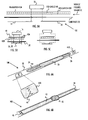
Figure 1 to 3 present a heart rate sensor structure to which the embodiments are applicable to; -
Figure 4A and 4B represent an electrostatic discharge (ESD) shield applied to the heart rate sensor structure according to some embodiments; -
Figure 5A shows an insulation applied to the ESD shield according to an embodiment; -
Figures 5B and 5C illustrate electrical connection between electrodes and an electronics module according to some embodiments -
Figures 6A and 6B depict grounding elements according to an embodiment; -
Figures 7A to 7C illustrate mounting of the electronics module according to some embodiments; -
Figure 8 shows the electronic module according to an embodiment; and -
Figure 9 illustrates a method according to an embodiment. - The following embodiments are exemplary. Although the specification may refer to "an", "one", or "some" embodiment(s) in several locations of the text, this does not necessarily mean that each reference is made to the same embodiment(s), or that a particular feature only applies to a single embodiment. Single features of different embodiments may also be combined to provide other embodiments.
- As said, it is common to measure heart activity while exercising in order to better monitor the effect of the exercise by the exerciser. Typically the measuring takes place with a heart rate activity sensor having electrodes against the skin of the exerciser. The location of the skin may be, e.g. the chest of the exerciser. The electrodes may measure voltage variations on the skin wherein the variations are due to the activity of the heart muscle. As a result, an electrocardiogram (ECG) signal may be generated. From the ECG signal, a variety of information may be derived. These include heart rate or heart rate variation, for example.
- The voltage changes may be in the range of millivolts, thus making the detection of the changes relatively difficult. Further, the conditions for measuring the heart activity while exercising are harsh due to, e.g., movement of the exerciser. At least partly for this reason, it is known to use a flexible textile as a substrate for mounting the electrodes which are placed against the chest of the exerciser. This is because the flexible textile is comfortable to the user compared to an integrated heart activity sensor structure. Furthermore, a flexible textile adapts better to the body shape of the exerciser and thereby ensures a better electrode contact to skin of the exerciser. An integrated heart activity sensor structure is disclosed in
US patents 5,491,474 and6,327,486 which are hereby incorporated by reference. - The integrated heart activity sensor structure is significantly different than a sensor structure applying the flexible textile in the point of view of the functionality and from the point of view of the implementation and assembly. For example, in the integrated heart activity sensor, electrodes and transmitter electronics are both functional entities molded into a single plastic casing. The plastic casing structure is simple, durable and relatively easy to manufacture. However, the structure is relatively rigid, thus having a negative impact on the user experience. On the contrary, in the sensor structure applying the flexible textile substrate, the electrode structure is typically implemented with conductive plastic or textile applied on an elastic strap.
- With reference to an embodiment shown in
Figures 1A and 1B , let us consider an embodiment of a heartactivity sensor structure 100 to which embodiments of the invention may be applied. The heartactivity sensor structure 100 may be attached to, e.g., astrap 10, which the exerciser 60 may wear around his/her body, such as chest, in order to hold electrodes, which are comprised in the heartactivity sensor structure 100, firmly against theskin 32 during the exercise. The exerciser 60 is the user of the heartactivity sensor structure 100. The heartactivity sensor structure 100 may comprisefastening elements activity sensor structure 100 tofastening elements strap 10, respectively. Thestrap 10 may comprise alength adjustment portion 10A adjusting the length of the strap by the exerciser 60. In an embodiment, the heartactivity sensor structure 100 comprises thestrap 10. It should be noted that the heartactivity sensor structure 100 may alternatively be attached to a garment, such as a shirt, a top, a bra, a wristband or trousers, instead of thestrap 10. In an embodiment, the garment is a glove, sock, a shirt arm, or a trouser leg. - The heart
activity sensor structure 100 may comprise one or more skin electrodes used to receive a physiological signal from the skin of the user 60, and an electronic circuit may be used to process and measure the physiological signal. The electronic circuit may be installed to anelectronics module 16 which may be fixed or detachably attached to thestrap 10 throughinstant connectors electronics module 16 may further comprise a battery for powering the heartactivity sensor structure 100, wherein the battery may be rechargeable or disposable. - The
electronics module 16 may also comprise a wireless transmitter circuitry. Then, the measuring device may realize exercise data transmission to a training computer 17, such as to a wrist watch or to a portable receiver, e.g. a mobile phone. In an embodiment, the data transmission carries exercise data to the training computer 17. In an embodiment, the transmitted signal may carry, for instance, ECG information. In an embodiment, theelectronics module 16 may be configured to measure, for instance, a physiological signal such as an electromyogram (EMG) from the skin of the user 60. In an embodiment, the heartactivity sensor structure 100 may also comprise a receiver for reception of data wirelessly from another device, such as from the training computer 17. In an embodiment, the received data may comprise information needed for upholding the communication connection and/or information needed for reconfiguring theelectronics module 16. Thus, the communication link to/from theelectronic module 16 may, in an embodiment, be bi-directional. - Let us now consider the structure of the heart
activity sensor structure 100 in greater detail with reference to an embodiment illustrated inFigures 2 and 3. Figures 2 and 3 illustrate different explosion views of the components of the heartactivity sensor structure 100, whereinFigure 2 is a side view, andFigure 3 is a perspective view. Referring toFigures 2 and 3 , the heartactivity sensor structure 100 comprises theflexible textile substrate 20, also known as a base layer or a supporting layer. Theflexible textile substrate 20 may form the base of the heartactivity sensor structure 100, and theflexible textile substrate 20 may comprise textile that supports the heartactivity sensor structure 100. Theflexible textile substrate 20 may comprise woven or knitted textile with elastic components, such as rubber and/or thermoplastic. Theflexible textile substrate 20 may form a substrate for mounting at least theelectrodes flexible textile substrate 20 may be in the order of 15 cm times 2 cm (length x width). - In an embodiment, the
flexible textile substrate 20 is bendably flexible (e.g. flexible so that thetextile substrate 20 may be bent, flexed or twisted without breaking). In an embodiment, theflexible textile substrate 20 is stretchably flexible (e.g. flexible so that it may be stretched in longitudinal and/or transversal direction). - The heart activity sensor structure may further comprise an
electrode layer 30 comprising one ormore electrodes electrodes flexible textile substrate 20 and configured to be placed against (contact) theskin 32 of the exerciser 60 either directly or indirectly. Theelectrodes skin 32 of the exerciser 60 and convey the detected electric signals to theelectronics module 16 connected to theconnectors electrodes connectors flexible textile substrate 20 and any layer between theflexible textile substrate 20 and theelectrode layer 30 to provide a galvanic connection between theelectrodes electronics module 16 disposed on opposite sides of theflexible textile substrate 20. In the embodiment shown inFigures 2 and 3 , theconnectors electrode layer 30, e.g. eachelectrode - An
intermediate insulation layer 22 may be provided as an intermediate layer between theflexible textile substrate 20 and theelectrode layer 30. Theintermediate insulation layer 22 functions as an electric insulation layer insulating theelectrode layer 30 from theflexible textile substrate 20. However in an embodiment, there is no need for theintermediate insulation layer 22 in case theflexible textile substrate 20 is not electrically conductive or is not directly contacting the electrodes. It should be noted though that theflexible textile substrate 20 may become electrically conducting after absorbing moisture during the exercise. - The definition of the
electrode layer 30 should be interpreted broadly to cover an electrode layer comprising at least twoskin electrodes skin electrodes skin electrodes skin 32 or a user's body part, such as chest or arm. Theelectrodes module 16 may comprise a differential amplifier to perform the amplifying of the difference signal. - When the number of
electrodes electrodes skin 32 of the exerciser 60 may be achieved by providing askin insulation layer 28 such that theelectrodes skin isolation layer 28 and theflexible textile substrate 20. Theskin isolation layer 28 reduces a short circuit between theelectrodes skin 32 of the exerciser 60. Theskin insulation layer 28 comprises insulating material, such as thermoplastic material, to carry out the isolation. In the case the number ofelectrodes skin insulation layer 28 may in some embodiments comprise a plurality of separate insulating portions to insulate thedifferent electrodes - As said earlier, the environmental conditions affect the success of the heart activity measurement, which may be based on detecting millivolt-range signals on the
skin 32 of the person 60. These environmental conditions may include static electricity and voltage generation from external sources, such as from the clothes or textiles of the exerciser 60. Accordingly, the heartactivity sensor structure 100, as shown inFigures 4A and 4B , further comprises an electrostatic discharge (ESD)shield 40 applied on one side of thetextile substrate 20 for protecting the at least twoelectrodes intermediate insulation layer 22, theskin insulation layer 28, theinstant connectors Figures 1 to 3 are not depicted in all of the Figures for reasons of simplicity. However, in an embodiment, at least some or all of the omitted elements are comprised in the various embodiments of the heartactivity sensor structure 100. - Static electricity may be seen as a contrary to current electricity, which flows via wires or other conductors and transmits energy. The phenomenon of static electricity may be caused whenever two surfaces contact and separate. When two materials are in contact, electrons may move from one material to the other, which leaves an excess of positive charge on one material, and an equal negative charge on the other. When the materials are separated they retain this charge imbalance. In the field of exercising, such two surfaces may be the
shirt 34 worn by the exerciser 60 and the heartactivity sensor structure 100. The ESD, on other hand, denotes a sudden flow of electricity between two objects, such as theshirt 34 worn by the exerciser 60 and the heartactivity sensor structure 100, and may be caused by the static electricity. The ESD may damage the heartactivity sensor structure 100 or the ESD may affect the accuracy of the heart activity measurement. However, advantageously due to the application of theESD shield 40, the possibly generated static electric charges may be conducted away from the vicinity of theelectrodes electrodes 24. 26. Such even distribution of the static electricity may be beneficial as then theskin electrodes skin 32 more accurately without being interrupted by the static electricity possibly generated on the opposite side of theelectrodes skin 32. - In an embodiment, the
ESD shield 40 is flexible. In an embodiment, the material of theflexible ESD shield 40 may be any conductive material, such as any metal, e.g. silver or copper. In an embodiment, theESD shield 40 may be made of a conductive metal tape, metal film or a conductive textile arranged on the opposite side of theelectrodes skin 32. Thus, theESD shield 40 may be on the opposite side of the at least twoelectrodes skin 32. - The
flexible ESD shield 40 may be applied on (attached to) theflexible textile substrate 20 and, more particularly, on either side of theflexible textile substrate 20. In an embodiment, theESD shield 40 is arranged on either surface of theflexible substrate 20. Let us look at these closer with reference toFigures 4A and 4B . InFigure 4A , theheart activity sensor 100 comprises at least the following plurality of layers: a first layer comprising the at least twoelectrodes skin 32 of the exerciser 60, a second layer arranged on top of the first layer and comprising thetextile substrate 20, and a third layer arranged at least partially on top of the second layer and comprising theESD shield 40. Thus, theelectrodes flexible substrate 20 and theflexible ESD shield 40 form layers which may be attached on top of each other. The attachment may be obtained with tape, wire, glue, stitching, knitting, weaving, for example, to mention only a few non-limiting options. The embodiment ofFigure 4A provides ease of implementation as the attachment between theelectrodes substrate 20 remains as usual. InFigure 4B , the order of the second and third layers is switched. - In an embodiment, as shown in
Figures 4A and 4B , theESD shield 40 covers at least the area in which the at least twoelectrodes electrodes activity sensor structure 100. FromFigures 4A and 4B it may be seen that theESD shield 40 is longer than the area in which the at least twoelectrodes ESD shield 40 exceeding vertical dotted lines inFigures 4A, 4B . The length may be defined in the horizontal dimension on the surface of theskin 32 when the heartactivity sensor structure 100 is worn against the chest of the exerciser 60, for example. Further, for example, inFigure 5B it may be seen that theESD shield 40 is wider than the area in which the at least twoelectrodes ESD shield 40 exceeding vertical dotted lines inFigure 5B . The width may be defined in the vertical dimension on the surface of theskin 32 when the heartactivity sensor structure 100 is worn against the chest of the exerciser 60, for example. In this way theESD shield 40 may protect and cover theelectrodes - In an embodiment, as shown in
Figure 5A , theflexible ESD shield 40 is electrically insulated from thetextile substrate 20 and from the at least twoelectrodes textile substrate 20 absorbs moisture during the exercise which may lead the textile substrate to become at least somewhat electrically conducting. Such electrical conduction of thetextile substrate 20 may cause any non-insulated ESD shield to be in electrical contact with theskin 32 via theconductive substrate 20 in an uncontrollable manner (depending on the location of the ESD shield 40). This may cause the signal-to-noise ratio (SNR) of the ECG signal to become weaker, thus leading to poorer ECG measurement accuracy. However owing to the electrical insulation applied to theESD shield 40 according to this embodiment, theESD shield 40 does not become uncontrollably contacted with theskin 32, for example. Further, it may be important that theESD shield 40 is not in electrical contact with theelectrodes ESD shield 40, an electrical insulation between theESD shield 40 and theelectrode 24, 26 (electrode layer 30) may be provided. - In an embodiment, the
ESD shield 40 comprises at least onelayer ESD shield 40, for example. In an embodiment, in case theESD shield 40 is on top of theflexible substrate 20, as shown inFigure 5A , theinsulation layer 42A may be omitted. However, in case theESD shield 40 is between theflexible substrate 20 and theelectrode layer 30, as is the case inFigure 4B , there may be need to apply both of the insulation layers 42A and 42B on both sides of theESD shield 40 in order to obtain electric insulation to theelectrodes flexible substrate 20. The insulation layers 42A, 42B may be wider and longer than theESD shield 40 in order to provide for efficient insulation. - In an embodiment, the
ESD shield 40 is formed into a sock-like structure comprising both of the insulation layers 42A, 42B, which provides for the electric insulation from theESD shield structure 40 to theflexible substrate 20 to theelectrodes Figure 5B which shows a horizontal view along theskin 32 of the person 60, the insulation layers 42A, 42B are attached to each other longitudinally at sides to form the sock-like structure. - In
Figures 4A to 5C , dashed lines show how the electrical connection between theelectrodes flexible textile substrate 20, theESD shield 40 and/or the insulation layer(s) 42A, 42B. The penetration may be provided with through-holes in theflexible textile substrate 20, in theESD shield 40 and/or in the insulation layer(s) 42A, 42B. The through-holes may be electrically insulated from the corresponding layer to which they are formed, e.g. from theflexible textile substrate 20, theESD shield 40 and/or the insulation layer(s) 42A, 42B. This may be beneficial so as conduct the measured ECG signals only to theelectronics module 16 and not to the layers of the heartactivity sensor structure 100. - For example, looking horizontally along the
skin 32 of the person 60,Figure 5B shows how the electrical connection penetrates theflexible textile substrate 20, theESD shield 40 and the insulation layer(s) 42A, 42B. However,Figure 5C shows how the electrical connection, such as a wire, may be arranged to circulate theESD shield 40 and the insulation layer(s) 42A, 42B from the sides (an upper side and a lower side when the heartactivity sensor structure 100 is worn on the chest of the exerciser 60). This may be beneficial to avoid implementing through-holes in theESD shield 40 and in the insulation layer(s) 42A, 42B. It should be noted that the electrical connection, such as wires, may travel at least partly inside theflexible substrate 20 to which theelectrodes - In an embodiment, the heart
activity sensor structure 100 further comprises, as shown inFigures 6A and 6B , at least onegrounding element ESD shield 40 and configured to contact theskin 32 of the exerciser 60 during use. This at least onegrounding element ESD shield 40 to theskin 32 and therefore acts as a gateway for the static electricity to pass to theskin 32 which may be seen as an electrical ground.Figure 6A shows the heartactivity sensor structure 100 from the side which is against theskin 32 of the exerciser 60 during use, whereasFigure 6B shows an opposite (top) view of the heartactivity sensor structure 100. In these Figures, it is assumed that theESD shield 40 is placed on top of theflexible textile substrate 20. The grounding element(s) 44A, 44B may be made of any conducting material. - In an embodiment, at least one location in which the at least one
grounding element flexible textile substrate 20. However, in order to provide more efficient grounding, in an embodiment, there are two groundingelements flexible textile substrate 20. An end of theflexible textile substrate 20 may be defined as an area between the longitudinal end of theflexible textile substrate 20 and theelectrode insulation layer ESD shield 40 may be connected to the at least onegrounding element - In an embodiment, the heart
activity sensor structure 100 further comprises a conductingstring structure 46 for coupling the at least onegrounding element ESD shield 40, wherein the conductingstring structure 46 penetrates thetextile substrate 20. As shown inFigures 6A and 6B , theESD shield 40 may be on top of thetextile substrate 20 whereas the electrode layer 30 (comprisingelectrodes 24, 26) is on the opposite side of thetextile substrate 20. In such case, the conductingstring structure 46 may provide a reliable and cost-efficient manner of electrically coupling theESD shield 40 to the grounding element(s) 44A, 44B. Thestring structure 46 may be, for example, a metal string attached (e.g. knitted, woven) to theESD shield 40 and to therespective grounding element activity sensor structure 100, thestring structure 46 may be easily added (e.g. knitted, woven) to the heartactivity sensor structure 100 without having to make any special through-holes or a like in theflexible textile substrate 20. Similarly, thestring structure 46 may penetrate the insulatinglayer 42B, if such is used. - In the case both the
electrode layer 30 and theESD shield 40 are on the same side of the flexible textile substrate 20 (not shown inFigures 6A, 6B ), the grounding element(s) 44A, 44B may be directly attached to theESD shield 40. In an embodiment referring to such order of the layers, there may be hole(s) in theinsulation layer 42B which allow theESD shield 40 to contact theskin 32 during use. In this embodiment, the portion(s) of theESD shield 40 touching theskin 32 may be seen as the grounding element(s) 44A, 44B. In yet one embodiment referring to such order of the layers, the grounding element(s) 44A, 44B may be also in this case connected to theESD shield 40 via the conductingstring structure 46 penetrating theinsulation layer 44B, if such exists. It should be noted that theintermediate insulation layer 22 ofFigure 3 may provide for the insulation between theelectrodes ESD shield 40, instead of theinsulation layer 44B. In such case, if the ESD shield is longer than theintermediate insulation layer 22, the portion(s) of theESD shield 40 extending further than theintermediate insulation layer 22 may be seen as the grounding element(s) 44A, 44B contacting theskin 32 of the exerciser 60. - In an embodiment, the heart
activity sensor structure 100 comprises anelectronics module 16 configured at least to transmit information related to the heart activity to thetraining computer 16, as indicated with reference toFigures 1A and 1B . Theelectronics module 16 may further comprise also other functional entities than the transmitter, as described earlier. - In an embodiment, as shown in
Figure 7A , theelectronics module 16 is detachably coupled to the at least twoelectrodes press studs electronics module 16 to/from thesubstrate 20. Further, in this case theESD shield 40 may comprise at least one through-hole electrodes electronics module 16 to pass theESD shield 40. As said, also thesubstrate 20 may comprise through-holes for allowing the electrical connection to pass. The through-holes may be electrically insulated from the layer to which they are formed. - However, in an embodiment, the
electronics module 16 is integrated (non-detachably) as part of the heartactivity sensor structure 100. In this case, theelectronics module 16 is, as shown inFigures 7B and 7C , mounted integrally to abase 50 of thesubstrate 20. In an embodiment, thebase 50 may be an engraving in thesubstrate 20, wherein the dimensions of the engraving may be appropriate to fit theelectronics module 16. In another embodiment, thebase 50 may be a location on the surface of thesubstrate 20 to which theelectronics module 16 is mounted to. The attachment between theelectronics module 16 and the base 50 may be obtained with glue, for example. Thebase 50 and theelectronics module 16 may comprise electrical connecting elements which provide for electrical connection between theelectronics module 16 and theelectrodes - In an embodiment, the heart
activity sensor structure 100 comprises a first part of theESD 40 on one side of theelectronics module 16 and a second part of theESD 40 on the other side of theelectronics module 16. The first and second parts may be electrically separated from each other. However, in an embodiment, theelectronics module 16 comprises a conducting structure configured to electrically connect the first part and the second part with each other. Such conducting structure may, e.g. in a casing that covers theelectronics module 16. - In an embodiment, the heart
activity sensor structure 100 and, more particularly, thebase 50 comprises electrically conductingperiphery element 52 coupled to theESD shield 40, as shown inFigures 7B, 7C and8 . Theperiphery element 52 may be in the form of a ring, an ellipse or a rectangular, to mention only a few possibly non-limiting options. The shape of theperiphery element 52 may depend on the shape of thebase 50, for example. Thus, theESD shield 40 may advantageously be a continuous element in front of theelectrodes periphery element 52 may be electrically connected to theESD shield 40, thus forming part of theESD shield 40. - In an embodiment, as shown in
Figure 8 , theelectronics module 16 comprises a casing covering theelectronics module 16. The casing may comprise an electrically non- conductiveouter surface 54 and electrically conductiveinner film 56. The electrically non- conductiveouter surface 54, which may be of plastic, may be beneficial so as no electric shocks are passed to the exerciser 60 touching theelectronics module 16. - There may be static electricity generated in the
electronics module 16 due to the movement of theshirt 34 against themodule 16, for example. Thus, in such case, the electrically conductiveinner film 56 may be of importance in protecting the electronic components of theelectronic module 16 from the ESD of the static electricity. Accordingly, in an embodiment, the electrically conductiveinner film 56 may be electrically coupled to theESD shield 40. This may take place either directly or via theperiphery element 52 of thebase 50. In the latter case, the electrically conductingperiphery element 52 may be coupled to the electrically conductiveinner film 56 of theelectronics module 16, as shown inFigure 8 . As a result, theinner film 56 may form part of the (continuous)ESD shield 40. This may provide protection for the electronic components inside theelectronics module 16 and also provide more efficient shielding of theelectrodes - In an embodiment, the surface of the
base 50 is electrically conductive and acts as part of theESD shield 40. There may be electric insulations applied in required portions of the base in order to ensure that, for example, the electrical connection between themodule 16 and theelectrodes ESD shield 40. - In an embodiment, the surface of the
base 50 is electrically conductive and theelectronics module 16 comprises the electrically conductiveinner film 56, and these electrically conductive portions are coupled to each other. This embodiment may create a Faraday's cage or shield for theelectronics module 16, thus protecting it from static electricity efficiently. - It should be noted that
Figures 4A to 5C ,7A ,7B , and8 are explosion Figures. Thus, it is clear that although the layers/components in the Figures are drawn separated from each other, the layers/components may be attached layer wise on top of each other to form the heartactivity sensor structure 100. In an embodiment, theESD shield 40 is at least partially inside theflexible textile substrate 20. - As shown in
Figure 8 , theelectronics module 16 may comprise a control circuitry (CTRL) 102, such as at least one processor, and at least one memory 104 including a computer program code, wherein the at least one memory 104 and the computer program code, are configured, with the at least one processor 104, to cause theelectronics module 16 to carry out a specific task with respect to the detected ECG signal, for example. The memory 104 may be implemented using any suitable data storage technology, such as semiconductor based memory devices, flash memory, magnetic memory devices and systems, optical memory devices and systems, fixed memory and removable memory. - The
control circuitry 102 may comprise an exercisedata generation circuitry 108 for generating the exercise data related to the detected ECG signals. The generated data may represent, for example, heart rate or heart rate variation. The apparatus may further comprisecommunication interface 106 comprising hardware and/or software for realizing communication connectivity according to one or more communication protocols, such as Bluetooth, Bluetooth Smart, wireless local area network (WLAN, WiFi), infrared (IR), wireless communication utilizing electric and/or magnetic fields, ANT, ANT+, or WIND. The communication connection may be applied for transmitting exercise data to the training computer 17 or to receive data from the training computer 17, for example. - There is also provided a method, as shown in
Figure 9 , comprising, instep 900, forming a flexible textile substrate. Instep 902, the method comprises applying at least twoelectrodes flexible textile substrate 20 with an electric insulation between each of the at least twoelectrodes electrodes skin 32 of an exerciser 60 in order to measure biosignals related to heart activity. Instep 904, the method comprises applying anelectrostatic discharge shield 40 on one side of theflexible textile substrate 20 for protecting the at least twoelectrodes - As used in this application, the term 'circuitry' refers to all of the following: (a) hardware-only circuit implementations, such as implementations in only analog and/or digital circuitry, and (b) combinations of circuits and software (and/or firmware), such as (as applicable): (i) a combination of processor(s) or (ii) portions of processor(s)/software including digital signal processor(s), software, and memory(ies) that work together to cause an apparatus to perform various functions, and (c) circuits, such as a microprocessor(s) or a portion of a microprocessor(s), that require software or firmware for operation, even if the software or firmware is not physically present. This definition of 'circuitry' applies to all uses of this term in this application. As a further example, as used in this application, the term 'circuitry' would also cover an implementation of merely a processor (or multiple processors) or a portion of a processor and its (or their) accompanying software and/or firmware. The term 'circuitry' would also cover, for example and if applicable to the particular element, a baseband integrated circuit or applications processor integrated circuit for a mobile phone or a similar integrated circuit in a server, a cellular network device, or another network device.
- Some of the functionalities performed by the
electronics module 16 embodiments as described may also be carried out in the form of a computer process defined by a computer program. The computer program may be in source code form, object code form, or in some intermediate form, and it may be stored in some sort of carrier, which may be any entity or device capable of carrying the program. For example, the computer program may be stored on a computer program distribution medium readable by a computer or a processor. The computer program medium may be, for example but not limited to, a record medium, computer memory, read-only memory, electrical carrier signal, telecommunications signal, and software distribution package, for example. Coding of software for carrying out the embodiments as shown and described is well within the scope of a person of ordinary skill in the art. - Even though the invention has been described above with reference to an example according to the accompanying drawings, it is clear that the invention is not restricted thereto but can be modified in several ways within the scope of the appended claims. Therefore, all words and expressions should be interpreted broadly and they are intended to illustrate, not to restrict, the embodiment. It will be obvious to a person skilled in the art that, as technology advances, the inventive concept can be implemented in various ways. Further, it is clear to a person skilled in the art that the described embodiments may, but are not required to, be combined with other embodiments in various ways.
Claims (16)
- A heart activity sensor structure (100), comprising:a flexible textile substrate (20);at least two electrodes (24, 26) with an electric insulation between each of the at least two electrodes, wherein the at least two electrodes (24, 26) are applied on one side of the flexible textile substrate (20) and configured to be placed against a skin (32) of an exerciser (60) in order to measure biosignals related to heart activity; andan electrostatic discharge shield (40) applied on one side the flexible textile substrate (20) for protecting the at least two electrodes (24, 26) from static electricity.
- The heart activity sensor structure (100) of claim 1, comprising at least the following plurality of layers:a first layer comprising the at least two electrodes (24, 26) and configured to be placed against the skin (32) of the exerciser (60);a second layer arranged on top of the first layer and comprising the flexible textile substrate (20); anda third layer arranged at least partially on top of the second layer and comprising the electrostatic discharge shield (40).
- The heart activity sensor structure (100) of claim 1, comprising at least the following plurality of layers:a first layer comprising the at least two electrodes and configured to be placed against the skin (32) of the exerciser (60);a third layer arranged on top of the first layer and comprising the electrostatic discharge shield (40); anda second layer arranged on top of the third layer and comprising the flexible textile substrate (20).
- The heart activity sensor structure (100) of any of claims 1 to 3, wherein the electrostatic discharge shield (40) covers at least the area of the heart activity sensor structure (100) in which the at least two electrodes (24, 26) are located.
- The heart activity sensor structure (100) of any of claims 1 to 4, wherein the electrostatic discharge shield (40) is electrically insulated from the flexible textile substrate (20) and from the at least two electrodes (24, 26).
- The heart activity sensor structure (100) of claim 5, wherein the electrostatic discharge shield (40) comprises at least one layer (42A, 42B) made of an electrically non-conducting material which provides for the electrical insulation.
- The heart activity sensor structure (100) of any of claims 1 to 6, further comprising:at least one grounding element (44A, 44B) coupled to the electrostatic discharge shield (40) and configured to contact the skin (32) of the exerciser (60).
- The heart activity sensor structure (100) of claim 7, wherein at least one location in which the at least one grounding element (44A, 44B) is configured to contact the skin (32) is at the at least one end of the flexible textile substrate (20).
- The heart activity sensor structure (100) of any of claims 7 to 8, further comprising:a conducting string structure (46) for coupling the at least one grounding element (44A, 44B) and the electrostatic discharge shield (40), wherein the conducting string structure (46) penetrates the flexible textile substrate (20).
- The heart activity sensor structure (100) of any of claims 1 to 9, further comprising:an electronics module (16) detachably coupled to the at least two electrodes (24, 26) and configured at least to transmit information related to the heart activity to a training computer (17), wherein the electrostatic discharge shield (40) comprises at least one through-hole (48A, 48B) in order to enable the coupling between the at least two electrodes (24, 26) and the electronics module (16).
- The heart activity sensor structure (100) of any of claims 1 to 9, further comprising:an electronics module (16) integrated as part of the heart activity sensor structure (100), coupled to the at least two electrodes (24, 26) and configured at least to transmit information related to the heart activity to a training computer (17).
- The heart activity sensor structure of claim 11, wherein the flexible textile substrate (20) comprises a base (50) for integrally mounting the electronics module (16), wherein the base (50) comprises electrically conducting periphery element (52) coupled to the electrostatic discharge shield (40).
- The heart activity sensor structure (100) of any of claims 11 to 12, wherein the electronics module (16) comprises a casing covering the electronics module (16), wherein the casing comprises an electrically non-conducting outer surface (54) and electrically conducting inner film (56), wherein the electrically conducting inner film (56) is electrically coupled to the electrostatic discharge shield (40).
- The heart activity sensor structure (100) of any of claims 10 to 13, further comprising:a first part of electrostatic discharge shield (40) on one side of the electronics module (16) and a second part of electrostatic discharge shield (40) on the other side of the electronics module (16), wherein the electronics module (16) comprises a casing having a conducting structure configured to electrically connect the first part of electrostatic discharge shield (40) to the second part of electrostatic discharge shield (40).
- A method for manufacturing a heart activity sensor structure (100), comprising:forming a flexible textile substrate (20);applying at least two electrodes (24, 26) on one side of the flexible textile substrate (20) with an electric insulation between each of the at least two electrodes (24, 26), wherein the at least two electrodes (24, 26) are configured to be placed against a skin (32) of an exerciser (60) in order to measure biosignals related to heart activity; andapplying an electrostatic discharge shield (40) on one side of the flexible textile substrate (20) for protecting the at least two electrodes (24, 26) from static electricity.
- The method of claim 15, wherein the flexible textile substrate (20), the at least two electrodes (24, 26), the electrostatic discharge shield (40) are each comprised in a dedicated layer, and the method comprises attaching the layers on top of each other.
Priority Applications (3)
| Application Number | Priority Date | Filing Date | Title |
|---|---|---|---|
| EP13167788.2A EP2803315B1 (en) | 2013-05-15 | 2013-05-15 | Heart activity sensor structure |
| US14/274,137 US10070798B2 (en) | 2013-05-15 | 2014-05-09 | Heart activity sensor structure |
| US14/643,759 US10314506B2 (en) | 2013-05-15 | 2015-03-10 | Heart activity sensor structure |
Applications Claiming Priority (1)
| Application Number | Priority Date | Filing Date | Title |
|---|---|---|---|
| EP13167788.2A EP2803315B1 (en) | 2013-05-15 | 2013-05-15 | Heart activity sensor structure |
Publications (2)
| Publication Number | Publication Date |
|---|---|
| EP2803315A1 true EP2803315A1 (en) | 2014-11-19 |
| EP2803315B1 EP2803315B1 (en) | 2019-10-02 |
Family
ID=48534145
Family Applications (1)
| Application Number | Title | Priority Date | Filing Date |
|---|---|---|---|
| EP13167788.2A Active EP2803315B1 (en) | 2013-05-15 | 2013-05-15 | Heart activity sensor structure |
Country Status (2)
| Country | Link |
|---|---|
| US (1) | US10070798B2 (en) |
| EP (1) | EP2803315B1 (en) |
Cited By (5)
| Publication number | Priority date | Publication date | Assignee | Title |
|---|---|---|---|---|
| US20170340226A1 (en) * | 2014-12-08 | 2017-11-30 | Nippon Telegraph And Telephone Corporation | Bioelectrode and garment |
| DE102016117354A1 (en) | 2016-09-15 | 2018-03-15 | Ntt New Textile Technologies Gmbh | On the skin portable electrode |
| CN108135516A (en) * | 2015-12-22 | 2018-06-08 | 京瓷株式会社 | Measurement sensor packaging body and measurement sensor |
| DE102018104774B3 (en) | 2018-03-02 | 2019-02-28 | Ntt New Textile Technologies Gmbh | On the skin portable electrode as well as garment |
| EP3928692A1 (en) | 2020-06-26 | 2021-12-29 | CSEM Centre Suisse d'Electronique et de Microtechnique SA - Recherche et Développement | Sensor device for potential and impedance measurements |
Families Citing this family (14)
| Publication number | Priority date | Publication date | Assignee | Title |
|---|---|---|---|---|
| FI20115759A0 (en) * | 2011-07-19 | 2011-07-19 | Polar Electro Oy | sports Clothing |
| US11219396B2 (en) | 2013-11-23 | 2022-01-11 | MAD Apparel, Inc. | System and method for monitoring biometric signals |
| US10321832B2 (en) | 2013-11-23 | 2019-06-18 | MAD Apparel, Inc. | System and method for monitoring biometric signals |
| US10292652B2 (en) | 2013-11-23 | 2019-05-21 | MAD Apparel, Inc. | System and method for monitoring biometric signals |
| US10398376B2 (en) | 2014-06-17 | 2019-09-03 | MAD Apparel, Inc. | Garment integrated electrical interface system and method of manufacture |
| US20150359485A1 (en) * | 2014-06-17 | 2015-12-17 | MAD Apparel, Inc. | Biometric signal conduction system and method of manufacture |
| DE102014009890A1 (en) * | 2014-07-04 | 2016-01-07 | Drägerwerk AG & Co. KGaA | Device for an impedance tomograph |
| US20160278702A1 (en) * | 2015-03-23 | 2016-09-29 | Zentan Technology Co., Ltd. | Physiological signal monitoring belt |
| CN104739403B (en) * | 2015-04-10 | 2017-08-25 | 中国科学院重庆绿色智能技术研究院 | Graphene nano wall flexibility electrocardioelectrode and preparation method thereof |
| CN108697374B (en) * | 2016-01-13 | 2021-09-17 | 丹麦专用绷带股份有限公司 | Apparatus and method for providing a measure of the circumference of a body part |
| DK3402401T3 (en) * | 2016-01-13 | 2021-06-07 | Specialbandager Dk As | Method for determining the effectiveness of a compression bandage |
| ES2951325T3 (en) | 2017-10-06 | 2023-10-19 | Fund Eurecat | Thoracic element adaptable to the body to detect, monitor and report on the physiological state of an individual |
| US11185284B2 (en) | 2019-01-02 | 2021-11-30 | Samsung Electronics Co., Ltd. | Wearable electrocardiogram device |
| CN109770894A (en) * | 2019-03-18 | 2019-05-21 | 长江大学 | A kind of cardiac monitoring band |
Citations (7)
| Publication number | Priority date | Publication date | Assignee | Title |
|---|---|---|---|---|
| US5491474A (en) | 1991-05-22 | 1996-02-13 | Polar Electro Oy | Telemetric transmitter unit |
| US6327486B1 (en) | 1998-06-22 | 2001-12-04 | Polar Electro Oy | Screen |
| US6453186B1 (en) * | 2001-04-13 | 2002-09-17 | Ge Medical Systems Information Technologies, Inc. | Electrocardiogram electrode patch |
| GB2438953A (en) * | 2006-06-08 | 2007-12-12 | Suunto Oy | A sensor for measuring a physiological signal and a method for manufacturing such a sensor. |
| EP2057943A1 (en) * | 2007-11-12 | 2009-05-13 | Polar Electro Oy | Electrode structure |
| US20100160763A1 (en) * | 2008-12-24 | 2010-06-24 | Dung-Han Tsai | Anti-interference physiological sensing device |
| WO2012104484A1 (en) * | 2011-01-31 | 2012-08-09 | Clothing Plus Oy | Textile substrate for measuring physical quantity |
Family Cites Families (7)
| Publication number | Priority date | Publication date | Assignee | Title |
|---|---|---|---|---|
| US3534727A (en) * | 1967-03-24 | 1970-10-20 | Nasa | Biomedical electrode arrangement |
| US4122843A (en) * | 1977-08-10 | 1978-10-31 | Electro-Technics, Inc. | Electrode system for a heart rate monitor |
| US4763660A (en) * | 1985-12-10 | 1988-08-16 | Cherne Industries, Inc. | Flexible and disposable electrode belt device |
| JP2631261B2 (en) * | 1993-02-23 | 1997-07-16 | 務 大竹 | Bioelectric signal recorder |
| FR2704131B1 (en) * | 1993-04-22 | 1995-06-30 | Odam | Sensor device for electrocardiogram. |
| FI20045503A (en) * | 2004-12-28 | 2006-06-29 | Polar Electro Oy | Sensor systems, accessories and heart rate monitors |
| US20130178728A1 (en) * | 2012-01-05 | 2013-07-11 | Garmin Switzerland Gmbh | Heart rate monitor having electrostatic discharge protective layer |
-
2013
- 2013-05-15 EP EP13167788.2A patent/EP2803315B1/en active Active
-
2014
- 2014-05-09 US US14/274,137 patent/US10070798B2/en active Active
Patent Citations (7)
| Publication number | Priority date | Publication date | Assignee | Title |
|---|---|---|---|---|
| US5491474A (en) | 1991-05-22 | 1996-02-13 | Polar Electro Oy | Telemetric transmitter unit |
| US6327486B1 (en) | 1998-06-22 | 2001-12-04 | Polar Electro Oy | Screen |
| US6453186B1 (en) * | 2001-04-13 | 2002-09-17 | Ge Medical Systems Information Technologies, Inc. | Electrocardiogram electrode patch |
| GB2438953A (en) * | 2006-06-08 | 2007-12-12 | Suunto Oy | A sensor for measuring a physiological signal and a method for manufacturing such a sensor. |
| EP2057943A1 (en) * | 2007-11-12 | 2009-05-13 | Polar Electro Oy | Electrode structure |
| US20100160763A1 (en) * | 2008-12-24 | 2010-06-24 | Dung-Han Tsai | Anti-interference physiological sensing device |
| WO2012104484A1 (en) * | 2011-01-31 | 2012-08-09 | Clothing Plus Oy | Textile substrate for measuring physical quantity |
Cited By (9)
| Publication number | Priority date | Publication date | Assignee | Title |
|---|---|---|---|---|
| US20170340226A1 (en) * | 2014-12-08 | 2017-11-30 | Nippon Telegraph And Telephone Corporation | Bioelectrode and garment |
| EP3231364A4 (en) * | 2014-12-08 | 2018-07-25 | Nippon Telegraph and Telephone Corporation | Bioelectrode and garment |
| AU2015362507B2 (en) * | 2014-12-08 | 2020-05-21 | Nippon Telegraph And Telephone Corporation | Bioelectrode and garment |
| US10799136B2 (en) | 2014-12-08 | 2020-10-13 | Nippon Telegraph And Telephone Corporation | Bioelectrode and garment |
| CN108135516A (en) * | 2015-12-22 | 2018-06-08 | 京瓷株式会社 | Measurement sensor packaging body and measurement sensor |
| DE102016117354A1 (en) | 2016-09-15 | 2018-03-15 | Ntt New Textile Technologies Gmbh | On the skin portable electrode |
| WO2018050172A1 (en) | 2016-09-15 | 2018-03-22 | Ntt New Textile Technologies Gmbh | Electrode for wearing on the skin |
| DE102018104774B3 (en) | 2018-03-02 | 2019-02-28 | Ntt New Textile Technologies Gmbh | On the skin portable electrode as well as garment |
| EP3928692A1 (en) | 2020-06-26 | 2021-12-29 | CSEM Centre Suisse d'Electronique et de Microtechnique SA - Recherche et Développement | Sensor device for potential and impedance measurements |
Also Published As
| Publication number | Publication date |
|---|---|
| US10070798B2 (en) | 2018-09-11 |
| US20140343391A1 (en) | 2014-11-20 |
| EP2803315B1 (en) | 2019-10-02 |
Similar Documents
| Publication | Publication Date | Title |
|---|---|---|
| EP2803315B1 (en) | Heart activity sensor structure | |
| US10314506B2 (en) | Heart activity sensor structure | |
| US9504396B2 (en) | Exercise apparel | |
| US9782124B2 (en) | Apparel for physiological telemetry during athletics | |
| EP2057943B1 (en) | Electrode structure | |
| US6327486B1 (en) | Screen | |
| CN205512398U (en) | Human biological electricity monitoring brassiere | |
| US11259580B2 (en) | Health monitoring garment and system | |
| WO2021165677A1 (en) | Electronics module for a wearable article | |
| US11937942B2 (en) | Wearable article and method of making the same | |
| US20230145601A1 (en) | Wearable Article, Assembly, and Method of Making the Same | |
| GB2596047A (en) | Article and method of making the same | |
| GB2596440A (en) | A wearable article | |
| US20210219895A1 (en) | Wearable muscle activity sensor and electrode | |
| US20230010015A1 (en) | Wearable Assembly Comprising a Wearable Article and an Electronics Module | |
| US20220296147A1 (en) | Electrode for organism | |
| US20230042347A1 (en) | Wearable Assembly Comprising a Wearable Article and an Electronics Module | |
| GB2547631A (en) | Heart rate and activity monitor system filters | |
| GB2592207A (en) | Electronics module for a wearable article | |
| GB2615480A (en) | Wearable assembly | |
| GB2592205A (en) | Electronics module for a wearable article | |
| GB2592362A (en) | Electronics module for a wearable article | |
| GB2607704A (en) | Compression garment | |
| GB2596269A (en) | Article and method of making the same |
Legal Events
| Date | Code | Title | Description |
|---|---|---|---|
| PUAI | Public reference made under article 153(3) epc to a published international application that has entered the european phase |
Free format text: ORIGINAL CODE: 0009012 |
|
| 17P | Request for examination filed |
Effective date: 20130515 |
|
| AK | Designated contracting states |
Kind code of ref document: A1 Designated state(s): AL AT BE BG CH CY CZ DE DK EE ES FI FR GB GR HR HU IE IS IT LI LT LU LV MC MK MT NL NO PL PT RO RS SE SI SK SM TR |
|
| R17P | Request for examination filed (corrected) |
Effective date: 20150511 |
|
| RBV | Designated contracting states (corrected) |
Designated state(s): AL AT BE BG CH CY CZ DE DK EE ES FI FR GB GR HR HU IE IS IT LI LT LU LV MC MK MT NL NO PL PT RO RS SE SI SK SM TR |
|
| GRAP | Despatch of communication of intention to grant a patent |
Free format text: ORIGINAL CODE: EPIDOSNIGR1 |
|
| STAA | Information on the status of an ep patent application or granted ep patent |
Free format text: STATUS: GRANT OF PATENT IS INTENDED |
|
| INTG | Intention to grant announced |
Effective date: 20190503 |
|
| GRAS | Grant fee paid |
Free format text: ORIGINAL CODE: EPIDOSNIGR3 |
|
| GRAA | (expected) grant |
Free format text: ORIGINAL CODE: 0009210 |
|
| STAA | Information on the status of an ep patent application or granted ep patent |
Free format text: STATUS: THE PATENT HAS BEEN GRANTED |
|
| AK | Designated contracting states |
Kind code of ref document: B1 Designated state(s): AL AT BE BG CH CY CZ DE DK EE ES FI FR GB GR HR HU IE IS IT LI LT LU LV MC MK MT NL NO PL PT RO RS SE SI SK SM TR |
|
| REG | Reference to a national code |
Ref country code: GB Ref legal event code: FG4D |
|
| REG | Reference to a national code |
Ref country code: CH Ref legal event code: EP Ref country code: AT Ref legal event code: REF Ref document number: 1185282 Country of ref document: AT Kind code of ref document: T Effective date: 20191015 |
|
| REG | Reference to a national code |
Ref country code: DE Ref legal event code: R096 Ref document number: 602013061166 Country of ref document: DE |
|
| REG | Reference to a national code |
Ref country code: IE Ref legal event code: FG4D |
|
| REG | Reference to a national code |
Ref country code: NL Ref legal event code: MP Effective date: 20191002 |
|
| REG | Reference to a national code |
Ref country code: LT Ref legal event code: MG4D |
|
| REG | Reference to a national code |
Ref country code: AT Ref legal event code: MK05 Ref document number: 1185282 Country of ref document: AT Kind code of ref document: T Effective date: 20191002 |
|
| PG25 | Lapsed in a contracting state [announced via postgrant information from national office to epo] |
Ref country code: LV Free format text: LAPSE BECAUSE OF FAILURE TO SUBMIT A TRANSLATION OF THE DESCRIPTION OR TO PAY THE FEE WITHIN THE PRESCRIBED TIME-LIMIT Effective date: 20191002 Ref country code: SE Free format text: LAPSE BECAUSE OF FAILURE TO SUBMIT A TRANSLATION OF THE DESCRIPTION OR TO PAY THE FEE WITHIN THE PRESCRIBED TIME-LIMIT Effective date: 20191002 Ref country code: NL Free format text: LAPSE BECAUSE OF FAILURE TO SUBMIT A TRANSLATION OF THE DESCRIPTION OR TO PAY THE FEE WITHIN THE PRESCRIBED TIME-LIMIT Effective date: 20191002 Ref country code: ES Free format text: LAPSE BECAUSE OF FAILURE TO SUBMIT A TRANSLATION OF THE DESCRIPTION OR TO PAY THE FEE WITHIN THE PRESCRIBED TIME-LIMIT Effective date: 20191002 Ref country code: LT Free format text: LAPSE BECAUSE OF FAILURE TO SUBMIT A TRANSLATION OF THE DESCRIPTION OR TO PAY THE FEE WITHIN THE PRESCRIBED TIME-LIMIT Effective date: 20191002 Ref country code: PL Free format text: LAPSE BECAUSE OF FAILURE TO SUBMIT A TRANSLATION OF THE DESCRIPTION OR TO PAY THE FEE WITHIN THE PRESCRIBED TIME-LIMIT Effective date: 20191002 Ref country code: GR Free format text: LAPSE BECAUSE OF FAILURE TO SUBMIT A TRANSLATION OF THE DESCRIPTION OR TO PAY THE FEE WITHIN THE PRESCRIBED TIME-LIMIT Effective date: 20200103 Ref country code: NO Free format text: LAPSE BECAUSE OF FAILURE TO SUBMIT A TRANSLATION OF THE DESCRIPTION OR TO PAY THE FEE WITHIN THE PRESCRIBED TIME-LIMIT Effective date: 20200102 Ref country code: PT Free format text: LAPSE BECAUSE OF FAILURE TO SUBMIT A TRANSLATION OF THE DESCRIPTION OR TO PAY THE FEE WITHIN THE PRESCRIBED TIME-LIMIT Effective date: 20200203 Ref country code: BG Free format text: LAPSE BECAUSE OF FAILURE TO SUBMIT A TRANSLATION OF THE DESCRIPTION OR TO PAY THE FEE WITHIN THE PRESCRIBED TIME-LIMIT Effective date: 20200102 Ref country code: FI Free format text: LAPSE BECAUSE OF FAILURE TO SUBMIT A TRANSLATION OF THE DESCRIPTION OR TO PAY THE FEE WITHIN THE PRESCRIBED TIME-LIMIT Effective date: 20191002 Ref country code: AT Free format text: LAPSE BECAUSE OF FAILURE TO SUBMIT A TRANSLATION OF THE DESCRIPTION OR TO PAY THE FEE WITHIN THE PRESCRIBED TIME-LIMIT Effective date: 20191002 |
|
| PG25 | Lapsed in a contracting state [announced via postgrant information from national office to epo] |
Ref country code: RS Free format text: LAPSE BECAUSE OF FAILURE TO SUBMIT A TRANSLATION OF THE DESCRIPTION OR TO PAY THE FEE WITHIN THE PRESCRIBED TIME-LIMIT Effective date: 20191002 Ref country code: HR Free format text: LAPSE BECAUSE OF FAILURE TO SUBMIT A TRANSLATION OF THE DESCRIPTION OR TO PAY THE FEE WITHIN THE PRESCRIBED TIME-LIMIT Effective date: 20191002 Ref country code: IS Free format text: LAPSE BECAUSE OF FAILURE TO SUBMIT A TRANSLATION OF THE DESCRIPTION OR TO PAY THE FEE WITHIN THE PRESCRIBED TIME-LIMIT Effective date: 20200224 Ref country code: CZ Free format text: LAPSE BECAUSE OF FAILURE TO SUBMIT A TRANSLATION OF THE DESCRIPTION OR TO PAY THE FEE WITHIN THE PRESCRIBED TIME-LIMIT Effective date: 20191002 |
|
| PG25 | Lapsed in a contracting state [announced via postgrant information from national office to epo] |
Ref country code: AL Free format text: LAPSE BECAUSE OF FAILURE TO SUBMIT A TRANSLATION OF THE DESCRIPTION OR TO PAY THE FEE WITHIN THE PRESCRIBED TIME-LIMIT Effective date: 20191002 |
|
| REG | Reference to a national code |
Ref country code: DE Ref legal event code: R097 Ref document number: 602013061166 Country of ref document: DE |
|
| PG2D | Information on lapse in contracting state deleted |
Ref country code: IS |
|
| PG25 | Lapsed in a contracting state [announced via postgrant information from national office to epo] |
Ref country code: RO Free format text: LAPSE BECAUSE OF FAILURE TO SUBMIT A TRANSLATION OF THE DESCRIPTION OR TO PAY THE FEE WITHIN THE PRESCRIBED TIME-LIMIT Effective date: 20191002 Ref country code: EE Free format text: LAPSE BECAUSE OF FAILURE TO SUBMIT A TRANSLATION OF THE DESCRIPTION OR TO PAY THE FEE WITHIN THE PRESCRIBED TIME-LIMIT Effective date: 20191002 Ref country code: DK Free format text: LAPSE BECAUSE OF FAILURE TO SUBMIT A TRANSLATION OF THE DESCRIPTION OR TO PAY THE FEE WITHIN THE PRESCRIBED TIME-LIMIT Effective date: 20191002 Ref country code: IS Free format text: LAPSE BECAUSE OF FAILURE TO SUBMIT A TRANSLATION OF THE DESCRIPTION OR TO PAY THE FEE WITHIN THE PRESCRIBED TIME-LIMIT Effective date: 20200202 |
|
| PLBE | No opposition filed within time limit |
Free format text: ORIGINAL CODE: 0009261 |
|
| STAA | Information on the status of an ep patent application or granted ep patent |
Free format text: STATUS: NO OPPOSITION FILED WITHIN TIME LIMIT |
|
| PG25 | Lapsed in a contracting state [announced via postgrant information from national office to epo] |
Ref country code: SK Free format text: LAPSE BECAUSE OF FAILURE TO SUBMIT A TRANSLATION OF THE DESCRIPTION OR TO PAY THE FEE WITHIN THE PRESCRIBED TIME-LIMIT Effective date: 20191002 Ref country code: IT Free format text: LAPSE BECAUSE OF FAILURE TO SUBMIT A TRANSLATION OF THE DESCRIPTION OR TO PAY THE FEE WITHIN THE PRESCRIBED TIME-LIMIT Effective date: 20191002 Ref country code: SM Free format text: LAPSE BECAUSE OF FAILURE TO SUBMIT A TRANSLATION OF THE DESCRIPTION OR TO PAY THE FEE WITHIN THE PRESCRIBED TIME-LIMIT Effective date: 20191002 |
|
| 26N | No opposition filed |
Effective date: 20200703 |
|
| PG25 | Lapsed in a contracting state [announced via postgrant information from national office to epo] |
Ref country code: SI Free format text: LAPSE BECAUSE OF FAILURE TO SUBMIT A TRANSLATION OF THE DESCRIPTION OR TO PAY THE FEE WITHIN THE PRESCRIBED TIME-LIMIT Effective date: 20191002 |
|
| PG25 | Lapsed in a contracting state [announced via postgrant information from national office to epo] |
Ref country code: LI Free format text: LAPSE BECAUSE OF NON-PAYMENT OF DUE FEES Effective date: 20200531 Ref country code: CH Free format text: LAPSE BECAUSE OF NON-PAYMENT OF DUE FEES Effective date: 20200531 Ref country code: MC Free format text: LAPSE BECAUSE OF FAILURE TO SUBMIT A TRANSLATION OF THE DESCRIPTION OR TO PAY THE FEE WITHIN THE PRESCRIBED TIME-LIMIT Effective date: 20191002 |
|
| REG | Reference to a national code |
Ref country code: BE Ref legal event code: MM Effective date: 20200531 |
|
| PG25 | Lapsed in a contracting state [announced via postgrant information from national office to epo] |
Ref country code: LU Free format text: LAPSE BECAUSE OF NON-PAYMENT OF DUE FEES Effective date: 20200515 |
|
| PG25 | Lapsed in a contracting state [announced via postgrant information from national office to epo] |
Ref country code: IE Free format text: LAPSE BECAUSE OF NON-PAYMENT OF DUE FEES Effective date: 20200515 |
|
| PG25 | Lapsed in a contracting state [announced via postgrant information from national office to epo] |
Ref country code: BE Free format text: LAPSE BECAUSE OF NON-PAYMENT OF DUE FEES Effective date: 20200531 |
|
| PG25 | Lapsed in a contracting state [announced via postgrant information from national office to epo] |
Ref country code: TR Free format text: LAPSE BECAUSE OF FAILURE TO SUBMIT A TRANSLATION OF THE DESCRIPTION OR TO PAY THE FEE WITHIN THE PRESCRIBED TIME-LIMIT Effective date: 20191002 Ref country code: MT Free format text: LAPSE BECAUSE OF FAILURE TO SUBMIT A TRANSLATION OF THE DESCRIPTION OR TO PAY THE FEE WITHIN THE PRESCRIBED TIME-LIMIT Effective date: 20191002 Ref country code: CY Free format text: LAPSE BECAUSE OF FAILURE TO SUBMIT A TRANSLATION OF THE DESCRIPTION OR TO PAY THE FEE WITHIN THE PRESCRIBED TIME-LIMIT Effective date: 20191002 |
|
| PG25 | Lapsed in a contracting state [announced via postgrant information from national office to epo] |
Ref country code: MK Free format text: LAPSE BECAUSE OF FAILURE TO SUBMIT A TRANSLATION OF THE DESCRIPTION OR TO PAY THE FEE WITHIN THE PRESCRIBED TIME-LIMIT Effective date: 20191002 |
|
| PGFP | Annual fee paid to national office [announced via postgrant information from national office to epo] |
Ref country code: FR Payment date: 20230516 Year of fee payment: 11 Ref country code: DE Payment date: 20230524 Year of fee payment: 11 |
|
| PGFP | Annual fee paid to national office [announced via postgrant information from national office to epo] |
Ref country code: GB Payment date: 20230523 Year of fee payment: 11 |