EP2777653A1 - Prosthesis delivery device - Google Patents
Prosthesis delivery device Download PDFInfo
- Publication number
- EP2777653A1 EP2777653A1 EP14275065.2A EP14275065A EP2777653A1 EP 2777653 A1 EP2777653 A1 EP 2777653A1 EP 14275065 A EP14275065 A EP 14275065A EP 2777653 A1 EP2777653 A1 EP 2777653A1
- Authority
- EP
- European Patent Office
- Prior art keywords
- prosthesis
- cannula
- handle
- proximal end
- positioner
- Prior art date
- Legal status (The legal status is an assumption and is not a legal conclusion. Google has not performed a legal analysis and makes no representation as to the accuracy of the status listed.)
- Granted
Links
- 230000014759 maintenance of location Effects 0.000 claims abstract description 18
- 230000000717 retained effect Effects 0.000 claims abstract description 4
- 230000007246 mechanism Effects 0.000 claims description 53
- 238000000034 method Methods 0.000 description 13
- 244000208734 Pisonia aculeata Species 0.000 description 7
- 239000003550 marker Substances 0.000 description 7
- 239000000463 material Substances 0.000 description 7
- 230000036961 partial effect Effects 0.000 description 7
- 230000008901 benefit Effects 0.000 description 3
- 230000008878 coupling Effects 0.000 description 3
- 238000010168 coupling process Methods 0.000 description 3
- 238000005859 coupling reaction Methods 0.000 description 3
- 238000002513 implantation Methods 0.000 description 3
- 230000002829 reductive effect Effects 0.000 description 3
- 238000013270 controlled release Methods 0.000 description 2
- 230000001419 dependent effect Effects 0.000 description 2
- 238000012986 modification Methods 0.000 description 2
- 230000004048 modification Effects 0.000 description 2
- 230000002441 reversible effect Effects 0.000 description 2
- 230000000007 visual effect Effects 0.000 description 2
- 239000004743 Polypropylene Substances 0.000 description 1
- 210000003484 anatomy Anatomy 0.000 description 1
- 210000000709 aorta Anatomy 0.000 description 1
- 238000005452 bending Methods 0.000 description 1
- 230000006835 compression Effects 0.000 description 1
- 238000007906 compression Methods 0.000 description 1
- 238000010276 construction Methods 0.000 description 1
- 239000002872 contrast media Substances 0.000 description 1
- 238000013461 design Methods 0.000 description 1
- 238000011010 flushing procedure Methods 0.000 description 1
- 230000023597 hemostasis Effects 0.000 description 1
- 238000002347 injection Methods 0.000 description 1
- 239000007924 injection Substances 0.000 description 1
- 238000003780 insertion Methods 0.000 description 1
- 230000037431 insertion Effects 0.000 description 1
- 230000000670 limiting effect Effects 0.000 description 1
- HLXZNVUGXRDIFK-UHFFFAOYSA-N nickel titanium Chemical compound [Ti].[Ti].[Ti].[Ti].[Ti].[Ti].[Ti].[Ti].[Ti].[Ti].[Ti].[Ni].[Ni].[Ni].[Ni].[Ni].[Ni].[Ni].[Ni].[Ni].[Ni].[Ni].[Ni].[Ni].[Ni] HLXZNVUGXRDIFK-UHFFFAOYSA-N 0.000 description 1
- 229910001000 nickel titanium Inorganic materials 0.000 description 1
- 238000012856 packing Methods 0.000 description 1
- -1 polypropylene Polymers 0.000 description 1
- 229920001155 polypropylene Polymers 0.000 description 1
- 230000008569 process Effects 0.000 description 1
- 230000000452 restraining effect Effects 0.000 description 1
- 238000000926 separation method Methods 0.000 description 1
- 229910000679 solder Inorganic materials 0.000 description 1
- 230000002792 vascular Effects 0.000 description 1
- 210000005166 vasculature Anatomy 0.000 description 1
Images


Classifications
-
- A—HUMAN NECESSITIES
- A61—MEDICAL OR VETERINARY SCIENCE; HYGIENE
- A61F—FILTERS IMPLANTABLE INTO BLOOD VESSELS; PROSTHESES; DEVICES PROVIDING PATENCY TO, OR PREVENTING COLLAPSING OF, TUBULAR STRUCTURES OF THE BODY, e.g. STENTS; ORTHOPAEDIC, NURSING OR CONTRACEPTIVE DEVICES; FOMENTATION; TREATMENT OR PROTECTION OF EYES OR EARS; BANDAGES, DRESSINGS OR ABSORBENT PADS; FIRST-AID KITS
- A61F2/00—Filters implantable into blood vessels; Prostheses, i.e. artificial substitutes or replacements for parts of the body; Appliances for connecting them with the body; Devices providing patency to, or preventing collapsing of, tubular structures of the body, e.g. stents
- A61F2/95—Instruments specially adapted for placement or removal of stents or stent-grafts
- A61F2/962—Instruments specially adapted for placement or removal of stents or stent-grafts having an outer sleeve
- A61F2/966—Instruments specially adapted for placement or removal of stents or stent-grafts having an outer sleeve with relative longitudinal movement between outer sleeve and prosthesis, e.g. using a push rod
- A61F2/9662—Instruments specially adapted for placement or removal of stents or stent-grafts having an outer sleeve with relative longitudinal movement between outer sleeve and prosthesis, e.g. using a push rod the middle portion of the stent or stent-graft is released first
-
- A—HUMAN NECESSITIES
- A61—MEDICAL OR VETERINARY SCIENCE; HYGIENE
- A61F—FILTERS IMPLANTABLE INTO BLOOD VESSELS; PROSTHESES; DEVICES PROVIDING PATENCY TO, OR PREVENTING COLLAPSING OF, TUBULAR STRUCTURES OF THE BODY, e.g. STENTS; ORTHOPAEDIC, NURSING OR CONTRACEPTIVE DEVICES; FOMENTATION; TREATMENT OR PROTECTION OF EYES OR EARS; BANDAGES, DRESSINGS OR ABSORBENT PADS; FIRST-AID KITS
- A61F2/00—Filters implantable into blood vessels; Prostheses, i.e. artificial substitutes or replacements for parts of the body; Appliances for connecting them with the body; Devices providing patency to, or preventing collapsing of, tubular structures of the body, e.g. stents
- A61F2/02—Prostheses implantable into the body
- A61F2/04—Hollow or tubular parts of organs, e.g. bladders, tracheae, bronchi or bile ducts
- A61F2/06—Blood vessels
- A61F2/07—Stent-grafts
-
- A—HUMAN NECESSITIES
- A61—MEDICAL OR VETERINARY SCIENCE; HYGIENE
- A61F—FILTERS IMPLANTABLE INTO BLOOD VESSELS; PROSTHESES; DEVICES PROVIDING PATENCY TO, OR PREVENTING COLLAPSING OF, TUBULAR STRUCTURES OF THE BODY, e.g. STENTS; ORTHOPAEDIC, NURSING OR CONTRACEPTIVE DEVICES; FOMENTATION; TREATMENT OR PROTECTION OF EYES OR EARS; BANDAGES, DRESSINGS OR ABSORBENT PADS; FIRST-AID KITS
- A61F2/00—Filters implantable into blood vessels; Prostheses, i.e. artificial substitutes or replacements for parts of the body; Appliances for connecting them with the body; Devices providing patency to, or preventing collapsing of, tubular structures of the body, e.g. stents
- A61F2/95—Instruments specially adapted for placement or removal of stents or stent-grafts
- A61F2/9517—Instruments specially adapted for placement or removal of stents or stent-grafts handle assemblies therefor
-
- A—HUMAN NECESSITIES
- A61—MEDICAL OR VETERINARY SCIENCE; HYGIENE
- A61F—FILTERS IMPLANTABLE INTO BLOOD VESSELS; PROSTHESES; DEVICES PROVIDING PATENCY TO, OR PREVENTING COLLAPSING OF, TUBULAR STRUCTURES OF THE BODY, e.g. STENTS; ORTHOPAEDIC, NURSING OR CONTRACEPTIVE DEVICES; FOMENTATION; TREATMENT OR PROTECTION OF EYES OR EARS; BANDAGES, DRESSINGS OR ABSORBENT PADS; FIRST-AID KITS
- A61F2/00—Filters implantable into blood vessels; Prostheses, i.e. artificial substitutes or replacements for parts of the body; Appliances for connecting them with the body; Devices providing patency to, or preventing collapsing of, tubular structures of the body, e.g. stents
- A61F2/95—Instruments specially adapted for placement or removal of stents or stent-grafts
- A61F2002/9505—Instruments specially adapted for placement or removal of stents or stent-grafts having retaining means other than an outer sleeve, e.g. male-female connector between stent and instrument
-
- A—HUMAN NECESSITIES
- A61—MEDICAL OR VETERINARY SCIENCE; HYGIENE
- A61F—FILTERS IMPLANTABLE INTO BLOOD VESSELS; PROSTHESES; DEVICES PROVIDING PATENCY TO, OR PREVENTING COLLAPSING OF, TUBULAR STRUCTURES OF THE BODY, e.g. STENTS; ORTHOPAEDIC, NURSING OR CONTRACEPTIVE DEVICES; FOMENTATION; TREATMENT OR PROTECTION OF EYES OR EARS; BANDAGES, DRESSINGS OR ABSORBENT PADS; FIRST-AID KITS
- A61F2/00—Filters implantable into blood vessels; Prostheses, i.e. artificial substitutes or replacements for parts of the body; Appliances for connecting them with the body; Devices providing patency to, or preventing collapsing of, tubular structures of the body, e.g. stents
- A61F2/95—Instruments specially adapted for placement or removal of stents or stent-grafts
- A61F2/962—Instruments specially adapted for placement or removal of stents or stent-grafts having an outer sleeve
- A61F2/966—Instruments specially adapted for placement or removal of stents or stent-grafts having an outer sleeve with relative longitudinal movement between outer sleeve and prosthesis, e.g. using a push rod
- A61F2002/9665—Instruments specially adapted for placement or removal of stents or stent-grafts having an outer sleeve with relative longitudinal movement between outer sleeve and prosthesis, e.g. using a push rod with additional retaining means
Definitions
- This invention relates to medical device delivery systems for the introduction of a medical device into a patient, in particular to an introducer/delivery device, systems and methods for delivering a prosthesis to an implantation site in a patient.
- aspects of the invention seek to provide an improved prosthesis delivery device.
- the proximal end of the positioner comprises a releasable capture mechanism engaging the distal end of the prosthesis.
- Embodiments of the present invention relate to delivery devices for prostheses, such as stents, grafts and stent grafts (collectively prostheses) in the vascular system of a patient.
- Embodiments of the invention relate to a prosthesis delivery system, device and method that provides the controlled release and implantation of a prosthesis in a controlled manner.
- Embodiments of the invention relate to an introducer/delivery device delivery handle that permits controlled release of a prosthesis from the introducer/delivery device.
- a prosthesis delivery device comprises a proximal end and a distal end, a prosthesis retention section at the proximal end, and a prosthesis retained on the prosthesis retention section.
- the prosthesis has a proximal end releasably attached at the prosthesis retention section and a distal end releasably attached at the prosthesis retention section.
- a sheath is slidably disposed over the prosthesis.
- a delivery handle near the distal end the delivery device comprises a rotatable inner cannula having a cannula lumen and cannula handle.
- the cannula handle is rotatable with the inner cannula, the inner cannula having a proximal end releasably engaged to the proximal end of the prosthesis.
- a positioner handle is releasably engaged with the cannula handle. Rotation of the inner cannula releases the proximal end of the prosthesis from the delivery device and withdrawal of the sheath from over the prosthesis releases the distal end of the prosthesis from the delivery device.
- prostheses such as stents, grafts and stent grafts into the aorta
- the disclosure is not so limited and may be applied to other vasculature or other body vessels or lumens.
- proximal refers to a direction that is generally closest to the heart during a medical procedure
- distal refers to a direction that is furthest from the heart during a medical procedure
- stent graft refers to a device that has a tubular body of biocompatible graft material and at least one stent fastened to the tubular body to define a lumen through the stent graft.
- the stent graft may be bifurcated and/or may include fenestrations, side arms, or the like. Other arrangements of stent grafts also are within the scope of this disclosure.
- the present delivery device operates to release a prosthesis from a delivery device at an implantation site within a body vessel.
- the delivery device may release the proximal end of a prosthesis from retention at and/or within the delivery system.
- the delivery device may release the proximal end, such as an end stent of a prosthesis from within a top cap holding the proximal end, such as an end stent of the prosthesis by twisting the cannula.
- the delivery device may further release the distal end of the stent graft through sheath pull back.
- the distal end of the prosthesis may be held to the delivery device prior to release by holding the distal end to a part of the delivery device.
- a distal capture feature on the delivery device holds the distal end of the prosthesis. While the sheath is in place over the prosthesis the distal end remains held or captured on the delivery device. With the withdrawal of the sheath in a distal direction and past the distal capture feature, the distal end of the prosthesis is released from the delivery device.
- a trigger wire is not needed to retain the distal end of prosthesis or to release the distal end.
- the delivery handle of the present delivery device includes one or more interlocks to prevent the physician from performing deployment steps out of sequence and from failing to perform or complete the delivery steps, which may be critical to the proper delivery of the prosthesis.
- the present device also provides a handle design that eliminates or reduces the need for the physician to remove his/her hands from the handle to complete delivery of the prosthesis, hence providing increased control over the device and the delivery process, which can mean the difference between a successful and a less than successful or unsuccessful procedure.
- the delivery device 100 has a deployment handle 102 which accomplishes the above functions.
- the handle has three primary grip points-a sheath handle 104, a positioner handle 106, and a cannula handle 108.
- the sheath handle 104 also may provide a valve housing for one or more valves for maintaining hemostasis.
- the sheath handle also may allow for flushing of the sheath. Exemplary valve structures that may be used as the one or more valves in the valve housing are shown in U.S. Patent/Publication Nos.
- the sheath handle 104 is gripped by the physician to withdraw the sheath from over the prosthesis.
- the second handle maintains the position of the prosthesis during all stages of deployment.
- the positioner handle 106 provides a consistent point of reference of the prosthesis during the procedure.
- the third handle provides control over the cannula and the proximal end of the delivery device. Specifically, the cannula handle 108 provides rotational control of the cannula and hence controls release of the proximal part or stent of the prosthesis from the delivery device.
- FIGS 1-5 illustrate prosthesis delivery device 100 with deployment handle 102 as it is operated by a user to release the proximal and distal ends of a prosthesis, such as a stent, graft or stent graft.
- Figures 6-10 illustrate an embodiment of the release of proximal end of the prosthesis with the deployment handle 102 of Figures 1-5 is operated as described below.
- Figures 1 and 2 show a partial side view of a prosthesis delivery device 100 having a distal end 101 a proximal end (not shown in Figures 1 and 2 , but 103 in later figures) and a deployment handle 102 near the distal end 101 of the delivery device 100.
- the deployment handle 102 is intended to remain outside of the patient.
- the deployment handle 102 preferably has three primary grip points, the sheath handle 104, the positioner handle 106 and the cannula handle 108.
- Any or all of the handles may be provided with gripping features that provide secure and/or ergonomic gripping of the handles by the physician.
- Any or all of the handles may further be provided with a mechanism or ability to provide the physician with tactile feedback while gripping and/or operating the handle.
- the deployment handle 102 includes a sheath 110, a sheath handle 104, a positioner 112 having a positioner shaft 114, a positioner handle 106, a cannula 116 having an inner lumen 118, a cannula handle 108, a cannula handle stop 120, a cannula safety 122, and a safety collar 124.
- the sheath handle 104 is connected to the sheath 110. As set forth above, sheath handle 104 provides a gripping point for the physician to withdrawn the sheath from over the prosthesis for deployment.
- the sheath 110 extends proximally of the sheath handle 104 and is disposed over the prosthesis prior to delivery of the prosthesis to the target treatment site.
- the positioner shaft 114 is operatively connected to the positioner handle 106, and extends proximally of the positioner handle 106.
- the proximal end 126 (shown in Figures 10-16 ) of the positioner handle 106 is located at or near the distal end 204 of a prosthesis 200 that is disposed on the delivery device 100.
- the positioner proximal end 126 may engage the distal end 204 of the prosthesis 200 by way of a releasable distal attachment and release mechanism 132.
- Positioner 112 further may include a positioner handle attachment region 134, for attaching to the cannula handle 108.
- the positioner handle attachment region 134 may be a keyed region with threading.
- a mechanism to limit full sheath pullback such as safety collar 124, may be disposed on the positioner 112 and is located adjacent to the proximal end 126 of the positioner handle 106.
- safety collar 124 is shown as disposed about the shaft of the positioner, other mechanisms, such as a protrusion or other feature that at least temporarily prevents full pullback of the sheath, may be used.
- the cannula 116 has a distal end 136 and a proximal end (not shown) and extends from the distal end 101 of the delivery device 100 to the proximal end 103 of the delivery device 100.
- the cannula 116 may have an inner lumen 118 that runs from the distal end 136 of the cannula 116 to the proximal end of the cannula and/or the delivery device 100.
- the cannula inner lumen 118 may accommodate a guide wire (not shown), one or more prosthesis release mechanisms (not shown), such as one or more trigger wires, and further may provide a passageway for the injection of a contrast medium through the lumen for viewing the delivery device and/or the prosthesis during a procedure.
- Positioner 112 has an inner lumen 138.
- Cannula 116 is at least partially disposed within the inner lumen 138 of positioner 112 and, in operation, may be axially slideable and rotatable relative to the positioner 112.
- Sheath has sheath inner lumen 140, which lumen inner diameter may closely approximate the outer diameter of the positioner 112.
- Positioner 112 is at least partially disposed over the cannula 116 and may be at least partially disposed within the sheath 110 and/or the prosthesis 200.
- the cannula 116 includes at least one cannula marker 142, which may be one or more marker bands, a notch, a color marker or other physical marker device that is physically viewable to the physician at least one point during the delivery procedure to indicate the completion of one or more delivery steps.
- Cannula 116 includes a cannula handle 108, and a cannula handle stop 120.
- Cannula handle 108 further may include a cannula/cannula handle connection element 144, which be keyed, and connection element 146.
- cannula handle 108 may be keyed through the cannula/cannula handle connection element 144 to the cannula 116.
- the cannula/cannula handle connection element 144 permits the cannula handle 108 to slide on the cannula 116, even as the cannula handle 108 rotates the cannula 116, to the cannula handle stop 120.
- the cannula/cannula handle connection element 144 is more fully described with reference to Figure 20 below.
- the cannula/cannula handle connection element 144 may be keyed and may include a ratchet mechanism, as known to those of skill in the art, to allow uni-directional turning.
- Cannula handle connection element 146 which engages the positioner handle attachment region 134, also may be keyed and is temporarily connected to the positioner handle attachment region 134.
- the positioner handle 106 is engaged with the cannula handle 108 through the positioner handle attachment region 134 and the cannula handle connection element 146.
- the connection between the cannula handle 116 and the positioner handle 106 is described here as a keyed connection, other connections may be contemplated or used.
- the cannula safety 122 which may be located on the cannula handle 108, locks the connection between the cannula handle 108 and positioner handle 106, until their disengagement is required.
- cannula safety 122 which may be located on the cannula handle 108, locks the connection between the cannula handle 108 and positioner handle 106, until their disengagement is required.
- Cannula safety 122 prevents rotational and axial movement of the cannula handle 108 relative to the positioner handle 106 until their disengagement.
- the cannula safety 122 may engage the positioner handle 106 through a latching or other engagement, such as a pin, clip and others known to one of skill in the art. Further, rather than be provided on the cannula handle, the safety may be provided on the positioner handle 106.
- the graft deployment handle 102 is shown with the sheath 110 partially withdrawn along the positioner 112 in the distal direction as indicated by the arrow.
- the physician places one hand on the sheath handle 104 (valve housing) and the second hand on the positioner handle 106, which is initially combined with the cannula handle 108.
- the physician slowly pulls the sheath handle in the direction of the arrow shown in Figure 2 toward the positioner handle to unsheath the prosthesis.
- the positioner shaft 114 is constructed of a material or in such a manner to have sufficient rigidity/stiffness to resist buckling of the positioner shaft 114 as sheath 110 is withdrawn over it.
- the safety collar 124 on the positioner shaft 114 prevents the sheath handle 104 from moving too far distally and prematurely releasing the distal attachment of the prosthesis.
- Figure 3 shows the deployment handle 102 with the cannula safety 122 disengaged from the positioner handle 106.
- the cannula safety 122 may be disengaged from the positioner handle 106 by moving the cannula safety 122 distally, as shown by the arrow in Figure 3 .
- the cannula handle 108 and cannula 116 are rotated as shown by the arrow in Figure 3 to disengage the cannula handle 108 from the positioner handle 106.
- the cannula handle 108 is connected to the cannula 116 through the cannula/cannula handle connection element 144 which causes the cannula 116 to turn as the cannula handle 108 is disengaged from the positioner handle 106.
- the cannula handle 108 As the cannula handle 108 rotates the cannula 116, the cannula handle 108 is removed from engagement with the positioner handle 116 by, for example, unthreading the cannula handle 108 from the positioner handle 106. As the unthreading or disconnection occurs, the cannula handle 108 separates from the positioner handle 106 and slides axially along the cannula 116 in a distal direction until it reaches the cannula handle stop 120 as shown in Figure 3 . As set forth above, the cannula handle 108 includes a mechanism, such as a ratchet mechanism, to permit rotation in a single direction.
- a mechanism such as a ratchet mechanism
- the number of turns required to separate the two handles is preferably equal to the minimum number of cannula turns required to release the proximal end of the prosthesis from its holding mechanism.
- the cannula handle 108 and the positioner handle 106 may be further withdrawn to pull the delivery device tip out of the proximal region of the prosthesis, such as the area where one or more stents are located at the proximal end, and into the main body of the prosthesis.
- the cannula handle 108 makes contact with cannula handle stop 120, further withdrawal of the handle causes pullback of the cannula 116 as shown by the arrow in Figure 4 to a desired point.
- Marker(s) 142 on the cannula gives the physician the visual indication that the cannula 116 is pulled back to the desired point.
- a further stop may be provided to limit the pullback of the cannula to the desired point.
- FIG. 5 further shows the completion of the retraction of the sheath 110.
- a mechanism 124 sheath stop
- sheath pullback such as a removable safety collar 124.
- the safety collar 124 is removed from the positioner shaft 114 and the sheath 110 is further withdrawn in a distal direction until the sheath 110 is adjacent to the proximal end of the positioner handle 106.
- the safety collar 124 may be a hinge ring that may be opened and removed from the positioner.
- the further withdrawal of the sheath 110 exposes the proximal end (shown in Figures 10-16 as element 126) of the positioner 112 and releases the distal end 204 of prosthesis 200 from the positioner 112, as discussed in further detail below.
- the various features described provide for sequential operation of the delivery device with various interlocks to prevent performing of the deployment steps in the wrong order and require completion or to prevent completion of the steps.
- the sheath 110 is pulled back to partially release the prosthesis from the sheath.
- the sheath is prevented from complete pullback due to a safety mechanism, such as a collar, that prevents further movement ( Figure 2 showing sheath handle moves in the direction of the arrow).
- a safety connecting the positioner handle and the cannula handle is released and the cannula handle is unthreaded from the positioner handle by rotating the cannula handle ( Figure 3 ).
- This unthreading also causes the cannula handle to move distally dues to its keyed relationship with the cannula ( Figure 3 ).
- the cannula handle moves distally until it meets the cannula stop, at which point the cannula and the cannula handle move distally together to fully disengage the cannula handle from the positioner handle ( Figure 3 ).
- the unthreading of the cannula handle from the positioner handle by rotating the cannula handle serves to rotate the proximal end of the cannula to release the proximal end of the prosthesis from the delivery device as will be explained in detail below.
- cannula handle 108 makes contact with cannula handle stop 120, further withdrawal of the handle causes pullback of the cannula 116 as shown by the arrow in Figure 4 .
- Marker(s) 142 on the cannula gives the physician the visual indication that the cannula 116 is pulled back to the desired point ( Figure 4 ).
- the safety collar 124 is then removed permitting further withdrawal of the sheath over and off the prosthesis. This further withdrawal of the sheath operates to release the distal end of the prosthesis from the delivery device as further explained below.
- Figures 6 and 7 show partial views of a proximal end and proximal portion of the delivery device 100, and illustrate an embodiment of a prosthesis proximal attachment and release mechanism for the release of the proximal end of the prosthesis using the delivery handle described above.
- Figure 6 shows the cannula 116, a tapered nose cone/dilator 148 having a proximal tip 150.
- nose cone 148 has a reverse distal taper 152 at its distal end 154.
- the nose cone surface 162 presents a smooth tapered surface to facilitate entry into and movement through a body vessel.
- An exemplary prosthesis proximal end attachment and release mechanism 156 is disposed at or near the distal end 154 of the nose cone 148 and on the cannula 116.
- Figure 7 shows the proximal end attachment and release mechanism 156 in greater detail.
- the proximal end attachment and release mechanism 156 comprises coiled member 164 which comprises a proximal end 166, a distal end 168, and a plurality of turns 170 disposed therebetween, as shown in Figure 7 .
- the proximal end 166 of the coiled member 164 is secured to the outer surface 172 of the cannula 116 using a suitable mechanism, such as a solder, weld, mechanical attachment, friction fit, crimp, or combination of these or other techniques and mechanisms. Accordingly, the proximal end 166 of the coiled member 164 cannot move relative to the outer surface 172 of the cannula 116.
- the proximal end 166 of the coiled member 164 comprises a first diameter d1, which may be approximately the same diameter, or slightly greater than, an outer diameter of the cannula 116.
- the distal end 168 of the coiled member 164 is unsecured relative to the outer surface 172 of the cannula 30, as shown.
- the distal end 168 of the coiled member 164 may comprise a second diameter d2, which is greater than the first diameter d1 of the proximal end 166 of the coiled member 164.
- the plurality of turns 170 are divided into a proximal series of turns 170a, which have the first diameter d1, and a distal series of turns 170b, which have the second diameter d2.
- the proximal series of turns 170a may be disposed in close proximity or abutting one another, as depicted in Figure 7 .
- the distal series of turns 170b may be spaced apart from one another a greater distance than the proximal series of turns 170a.
- the distal series of turns 170b are spaced apart a predetermined distance denoted by spacing 176.
- stent graft 200 is disposed on the device and has a proximal end 202 and distal end 204.
- Stent graft 200 includes, in this example, a graft material 206, a bare proximal top stent 208 (though the disclosure is not so limited), and one or more stents 210 attached to the graft material 206.
- the stents 210 may be on either or both surfaces of the tube of graft material 206 and may have the characteristics of self expanding stents, balloon expanding stents, or both, depending on the desired stent characteristics.
- a proximal prosthesis retention mechanism 156 (shown in the dotted box, which is not part of the device) may be disposed.
- the release mechanism may include the coiled member 164 discussed with regard to Figures 6 and 7 , and further include at least one suture loop 212.
- FIGs 8 and 9 an exemplary coupling of the stent graft 200 to the delivery device 100 of Figure 1-5 is shown and described.
- the stent graft 200 has an uncoupled state in which the stent graft 200 is positioned coaxially over the cannula 116 with the proximal end 202 of the stent graft 200 in longitudinal proximity relative to the distal end 216 of the coiled member 164, as shown in Figure 9 .
- one or more suture loops 212 that are coupled to the proximal apices 214 of the stent 208 are threaded around the distal end 160 of the coiled member 164 one at a time, preferably until all of the suture loops 212 are coupled to the coiled member 164.
- Such coupling may be achieved by rotating the cannula 116 in a clockwise direction until the proximal end 202 of the stent 208 is sufficiently compressed in a radially inward direction, as depicted in Figure 8 .
- the suture loops 212 are further accommodated within a spacing between the distal series of turns.
- the suture loops 212 preferably are coupled to the coiled member 164 in a manner in which at least one suture loop 212 is positioned around at least one full turn of the distal series of turns, and preferably around at least 1.5 turns at the distal end 168 of the coiled member 164, thereby reducing the likelihood of inadvertent uncoupling of the suture loops 212 from the coiled member 164.
- the coupling shown in Figure 9 secures the stent 208 to the cannula 116 via the coiled member 164 in a manner that may subsequently facilitate insertion of the subassembly comprising the cannula 116 and the stent graft 200 into an outer sheath.
- the outer sheath is configured to radially restrain other regions of the stent graft 200 for delivery to a target site within a patient's anatomy.
- the suture loops 212 may be coupled to every other proximal apex 214 as shown in Figures 8 to restrain the stent 208 during delivery.
- the suture loops 212 are not coupled to the second proximal apices 214b, which may comprise barbs.
- the adjacent second proximal apices 214b also may be indirectly pulled in a radially inward direction during delivery.
- the configuration of the stent 208 facilitates the indirect compression of the adjacent second proximal apices 214b.
- Figures 10-14 illustrate the release of the distal end of the stent graft, with further reference to Figures 15 and 16 for particular embodiments of the distal end attachment and release mechanism.
- Figure 10 shows the stent graft 200 loaded on the device and compressed by the sheath 110. In operation, the operator withdraws the sheath 100 in the direction indicated by the arrow shown in Figure 11 .
- the cannula 116 may be rotated in a counter-clockwise direction (as shown by the arrow in Figure 12 ) until the suture loops 212 are uncoupled from the coiled member 164, i.e., in a reverse manner from which the suture loops 212 were coupled to the coiled member 164.
- the stent 208 then may be deployed as shown in Figures 8 and 9 , and the remainder of the stent graft 200 may be deployed by further retraction of the sheath 110 (as shown by the arrows in Figures 13 and 14 ) or actuation of any other devices that are constraining the remainder of the stent graft 200.
- the proximal end of the stent 208 is radially restrained without the use of conventional trigger wires that span a full longitudinal length of the delivery system. Accordingly, the radial profile of the delivery system may be reduced without the provision of multiple trigger wires and one or more associated sleeves to house the trigger wires, thereby reducing packing density of the system. Moreover, deployment may be simplified as reduced deployment forces are expected to be needed relative to the use of conventional trigger wires.
- deployment of a stent using the described device comprising at least one coiled member may allow for more precise positioning of the stent.
- deployment using the coiled member may provide a more controlled unwinding of the associated portion of the stent, whereas the release of conventional trigger wires may require higher deployment forces that can cause a portion of the stent to jump longitudinally, thereby potentially deploying the stent offset from the intended target site.
- Figures 12-14 demonstrate the continued operation of the device to release the distal end 204 of the stent graft 200.
- the distal end 204 of the stent graft is attached to the device by way of at least one distal end capture mechanism 132 on the positioner 112 which engages a corresponding element at the distal end of the stent graft 204, such as a looped portion 306.
- the sheath is fully withdrawn in the direction of the arrow and removed from the stent graft 200.
- the full withdrawal of the sheath 110 exposes the distal end 204 of the stent graft 200 and the distal end 204 of the stent graft 200 is released by releasing the loop 216 from the releasable distal attachment and release mechanism 132.
- FIGS 15A-D are perspective views of a prosthesis distal end with an exemplary distal attachment and release mechanism.
- the sheath 110 is shown as transparent to allow objects covered by the sheath 110 to be visible.
- the sheath 110 may actually be opaque or transparent.
- positioner 112 has releasable distal attachment and release mechanism 132 at the proximal end 126 of positioner 112.
- capture mechanism comprises a capture wire 302 on the positioner 112 which is bent to engage a loop 306 or other configuration at the distal end 204 of the stent graft 200.
- the sheath 110 Prior to release of the distal end, the sheath 110 is over the capture wire 302.
- the space shown between the sheath 110, the positioner 112, and capture wire 302 in Figures 15A-D may be exaggerated to show the components device more clearly.
- the sheath 110 While the sheath 110 is disposed over the capture wire 302, as shown in Figures 15A-D , the sheath 110 prevents the bent capture wire 302 from straightening. A close fit of the sheath 110 over the positioner 112 and capture wire 302, as shown in Figure 15B prevents the looped portion 306 from releasing or becoming detached from the capture wire 302 while the sheath is positioned over it. As shown, at least a portion of the capture wire 302 is affixed to the positioner 112. As shown, another portion 309 of the capture wire 302 may be free and not attached to positioner.
- the unattached section 309 of the capture wire 302 may include an atraumatic section 304.
- the atraumatic section 304 may prevent damage to a vessel wall or body cavity if the unattached section 309 of the capture wire 302 contacts vessel wall or body cavity.
- the atraumatic section 304 may take any shape that prevents or minimizes damage to a vessel wall or body cavity that comes in contact with the atraumatic section 304, including, for example, a rounded ball, curved segment, curved end, or cushioned area.
- the capture wire 302 may include one or more bends in the unattached section of the capture wire 302 when the sheath 110 covers the capture wire 302.
- the bend may be approximately 180 degrees.
- the unattached section of the capture wire 302 is held in the bent position by the presence of the sheath 110 where the unattached section 309 is prevented from straightening out and removing the bend 308.
- the capture wire 302 may be composed of any material capable of deforming and later returning to its un-deformed shape, such as bending and later straightening.
- the capture wire 302 may consist of, for example, nitinol or polypropylene filament.
- the length, thickness, and flexibility of the capture wire 302 may be varied depending on the application. For example, a thicker or less flexible capture wire 302 may be used if the looped portion 306 applies a relatively large force to the capture wire 302.
- a longer capture wire 302 may be used if the diameter of the looped portion 306 is relatively large or if the space between the proximal end 126 of the positioner 112 is relatively large.
- the capture wire 302 may return to its un-deformed or unbent shape automatically upon removal of the sheath 110 from over it.
- the material properties of capture wire 302 may cause it to return to an unbent or substantially straight shape without any external force applied.
- Figure 15D shows the sheath withdrawn from the capture wire 302. Removal from the sheath from over the capture wire 302 permits the capture wire 302 to be relieved from its bent shape and release loop 306 and consequently releasing the distal end 204 of the prosthesis. After the distal end is released, the device may be removed from the prosthesis and the body vessel.
- Figures 16-18 are further embodiments of a releasable distal attachment and release mechanism 132.
- the sheath 110 is shown as transparent to allow objects covered by the sheath to be visible.
- the sheath 110 may actually be opaque or transparent.
- the space shown between the sheath 110 and the positioner may be exaggerated to show the components of the exemplary medical device delivery systems more clearly, and the inner diameter of the sheath 110 may more approximate the outer diameter of the positioner 112.
- the capture wire 302 may include a bend 308 and an atraumatic portion 304 with the bend maintained by the presence of the sheath over the positioner 112 and the capture wire 302.
- the positioner has a recessed area 310 in the surface of the positioner for receiving the capture wire 302.
- the recessed area 310 may contain part or all of the unattached section of capture wire 302, as shown in Figure 16A , and may have a similar configuration to the unattached section 309, or any other shape that is capable of substantially containing the unattached section 309 of capture wire 302.
- Containing the unattached section 309 of capture wire 302 within the recessed area 310 may reduce the overall diameter of the delivery device, because space between the sheath and the positioner does not have to be maintained to accommodate the capture wire 302.
- the attached end of the capture wire 302 may attached to the positioner proximal end within the recess 310 as shown in Figure 16 or it may be attached at another area of the surface of the positioner as shown in Figure 17 .
- the capture wire 302 When the capture wire 302 is bent, the free or unattached end of the capture wire 302 may be held almost entirely within the recess when the sheath is disposed over the recess as shown in Figures 16A and 17A .
- the capture wire 302 of Figure 15 once the sheath 110 is withdrawn, the capture wire 302 resumes its unbent or previous shape and releases the distal end of the prosthesis.
- the capture wire 302 fixed section may be attached at any location around the perimeter of the positioner proximal end, including away from the recessed area as shown in Figure 17A . Attaching the fixed section of capture wire 302 at a location outside of the recessed area may allow the bend 308 to have a larger radius of curvature. A large radius of curvature may reduce the strain on capture wire 302 and improve is durability.
- FIG 18 shows another embodiment of the releasable distal attachment and release mechanism 132.
- the releasable distal attachment and release mechanism 132 forms a closed loop.
- the closed loop has two attached or fixed ends that are attached to the positioner at the proximal end.
- the loop lies against the positioner and is held there by the sheath.
- the loop engages a corresponding loop or hook at the distal end of the prosthesis.
- the loop is permitted to spring away from the positioner in a proximal direction and release the distal end of the prosthesis by releasing the corresponding loop or hook.
- FIG. 19A-D A further embodiment of the capture mechanism is shown at Figures 19A-D .
- This embodiment and further details of its construction and use are set forth in the concurrently filed application entitled "Wireless Medical Device Release Mechanism," (Inventors William Havel, Matt Huser and Richard Hadley).
- the proximal end of the positioner itself has a configuration that engages a portion of the distal end of the prosthesis, such as a loop as described above.
- the engagement element 306 at the distal end of the prosthesis may be a separate loop such as a suture loop, a hook, a part of the stent, or the like.
- the engagement element 306 of the prosthesis engages a recessed region 310 of the proximal end of the positioner 112 such that the engagement element 306 is held in the recessed region 310.
- the engagement element 306 is held within the recess against an inclined surface 312 which may be inclined away from the prosthesis distal end, thus capturing the engagement element 306 in the recess.
- the recess 310 may take the form of that sent forth in Figures 1-16 of the concurrently filed application to Havel et al., entitled “Wireless Medical Device Release Mechanism,” incorporated by reference herein, for example that shown as element 506 in Figures 5 and 7 , and the accompanying text, of the above incorporated reference or that shown in Figures 8 and 9 of the incorporated reference above which includes a looped capture mechanism releasably embedded in a recess in the surface of the positioner.
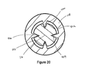
- figure 20 show an exemplary cannula/cannula connection element 144 (though not shown in this figure, cannula 116 includes a lumen as set forth above).
- Figure 20 is cross-section of cannula 116 and cannula handle 108.
- Connection element 114 comprises one or more radially projections 400 from the inner surface 402 of the cannula handle 108 cooperating with one or more slots, channels, indents, recesses or the like 404 in cannula outer surface 172.
- the cannula/cannula connection element provides for rotation of the cannula with rotation of the cannula handle while also permitting longitudinal movement of the cannula handle along the cannula.
Abstract
Description
- This invention relates to medical device delivery systems for the introduction of a medical device into a patient, in particular to an introducer/delivery device, systems and methods for delivering a prosthesis to an implantation site in a patient.
- Aspects of the invention seek to provide an improved prosthesis delivery device.
- According to an aspect of the invention, there is provided a device as in claim 1.
- According to an aspect of the invention, there is provided a device as in claim 12.
- In embodiments, the proximal end of the positioner comprises a releasable capture mechanism engaging the distal end of the prosthesis.
- Embodiments of the present invention relate to delivery devices for prostheses, such as stents, grafts and stent grafts (collectively prostheses) in the vascular system of a patient. Embodiments of the invention relate to a prosthesis delivery system, device and method that provides the controlled release and implantation of a prosthesis in a controlled manner. Embodiments of the invention relate to an introducer/delivery device delivery handle that permits controlled release of a prosthesis from the introducer/delivery device.
- In an embodiment, a prosthesis delivery device comprises a proximal end and a distal end, a prosthesis retention section at the proximal end, and a prosthesis retained on the prosthesis retention section. The prosthesis has a proximal end releasably attached at the prosthesis retention section and a distal end releasably attached at the prosthesis retention section. A sheath is slidably disposed over the prosthesis. A delivery handle near the distal end the delivery device comprises a rotatable inner cannula having a cannula lumen and cannula handle. The cannula handle is rotatable with the inner cannula, the inner cannula having a proximal end releasably engaged to the proximal end of the prosthesis.
- Further, a positioner handle is releasably engaged with the cannula handle. Rotation of the inner cannula releases the proximal end of the prosthesis from the delivery device and withdrawal of the sheath from over the prosthesis releases the distal end of the prosthesis from the delivery device.
- Other systems, methods, features and advantages of embodiments of the invention will be, or will become, apparent to one with skill in the art upon examination of the following figures and detailed description. It is intended that all such additional systems, methods, features and advantages be within the scope of the invention, and be encompassed by the following claims.
- Embodiments of the invention are described below, by way of example only, with reference to the accompanying drawings.
-
Figure 1 is a partial side view of a prosthesis delivery device, in particular the handle portion of the device at the distal end of the delivery device. -
Figure 2 is a further view of the prosthesis delivery device ofFigure 1 at a stage of deployment of a prosthesis. -
Figure 3 is a further side view of the prosthesis delivery device of theFigure 1 at another stage of deployment of the prosthesis. -
Figure 4 is a further side view of the prosthesis delivery device of theFigure 1 at another stage of deployment of the prosthesis -
Figure 5 is a further side view of the prosthesis delivery device of theFigure 1 at another stage of deployment stage of deployment of the prosthesis -
Figure 6 is a partial side view of a proximal end of a delivery device with an exemplary prosthesis end attachment and release mechanism. -
Figure 7 is a close up partial side view of the proximal end attachment and release mechanism -
Figure 8 shows a partial side view of the delivery device ofFigure 6 having a prosthesis on the delivery device with the proximal end stent attached to the proximal end attachment and release mechanism. -
Figure 9 shows the device ofFigure 8 with the end stent released from the proximal end attachment and release mechanism. -
Figures 10-14 show further partial side views of the device ofFigures 8 and 9 and the procedure for releasing the distal end of the prosthesis from the distal end attachment and release mechanism and releasing the proximal end of the prosthesis from the proximal end attachment and release mechanism. -
Figures 15A-D are perspective views of the prosthesis distal end with exemplary distal end attachment and release mechanisms. -
Figures 16A-B are perspective views of the prosthesis distal end with another exemplary distal end attachment and release mechanism. -
Figures 17A-B are perspective views of the prosthesis distal end with another exemplary distal end attachment and release mechanism. -
Figures 18A-B are perspective views of the prosthesis distal end with another exemplary distal end attachment and release mechanism. -
Figures 19A-D are perspective views of the prosthesis distal end with another exemplary distal end attachment and release mechanism. -
Figure 20 is a cross-sectional view of the cannula/cannula handle connection element. - The embodiments described in this disclosure will be discussed generally in relation to deployment of prostheses, such as stents, grafts and stent grafts into the aorta, but the disclosure is not so limited and may be applied to other vasculature or other body vessels or lumens.
- In the present application, the term "proximal" refers to a direction that is generally closest to the heart during a medical procedure, while the term "distal" refers to a direction that is furthest from the heart during a medical procedure.
- The term "stent graft" refers to a device that has a tubular body of biocompatible graft material and at least one stent fastened to the tubular body to define a lumen through the stent graft. The stent graft may be bifurcated and/or may include fenestrations, side arms, or the like. Other arrangements of stent grafts also are within the scope of this disclosure.
- The present delivery device operates to release a prosthesis from a delivery device at an implantation site within a body vessel. In particular, the delivery device may release the proximal end of a prosthesis from retention at and/or within the delivery system. For example, the delivery device may release the proximal end, such as an end stent of a prosthesis from within a top cap holding the proximal end, such as an end stent of the prosthesis by twisting the cannula.
- The delivery device may further release the distal end of the stent graft through sheath pull back. The distal end of the prosthesis may be held to the delivery device prior to release by holding the distal end to a part of the delivery device. In one example, a distal capture feature on the delivery device holds the distal end of the prosthesis. While the sheath is in place over the prosthesis the distal end remains held or captured on the delivery device. With the withdrawal of the sheath in a distal direction and past the distal capture feature, the distal end of the prosthesis is released from the delivery device. In this example, a trigger wire is not needed to retain the distal end of prosthesis or to release the distal end.
- The delivery handle of the present delivery device includes one or more interlocks to prevent the physician from performing deployment steps out of sequence and from failing to perform or complete the delivery steps, which may be critical to the proper delivery of the prosthesis. The present device also provides a handle design that eliminates or reduces the need for the physician to remove his/her hands from the handle to complete delivery of the prosthesis, hence providing increased control over the device and the delivery process, which can mean the difference between a successful and a less than successful or unsuccessful procedure.
- As described more fully below with regard to
Figure 1-5 , thedelivery device 100 has adeployment handle 102 which accomplishes the above functions. The handle has three primary grip points-asheath handle 104, apositioner handle 106, and acannula handle 108. Thesheath handle 104 also may provide a valve housing for one or more valves for maintaining hemostasis. The sheath handle also may allow for flushing of the sheath. Exemplary valve structures that may be used as the one or more valves in the valve housing are shown inU.S. Patent/Publication Nos. 2012/0310178 ;2005/0171479 ;2007/0078395 ;2008/0157017 ;2011/0054585 ; and2012/0238958 in which the descriptions and operations of the valves disclosed are incorporated by reference in their entirety herein. In operation, thesheath handle 104 is gripped by the physician to withdraw the sheath from over the prosthesis. - The second handle, the positioner handle 106, maintains the position of the prosthesis during all stages of deployment. The
positioner handle 106 provides a consistent point of reference of the prosthesis during the procedure. The third handle, the cannula handle 108, provides control over the cannula and the proximal end of the delivery device. Specifically, thecannula handle 108 provides rotational control of the cannula and hence controls release of the proximal part or stent of the prosthesis from the delivery device. -
Figures 1-5 illustrateprosthesis delivery device 100 withdeployment handle 102 as it is operated by a user to release the proximal and distal ends of a prosthesis, such as a stent, graft or stent graft.Figures 6-10 illustrate an embodiment of the release of proximal end of the prosthesis with the deployment handle 102 ofFigures 1-5 is operated as described below. -
Figures 1 and 2 show a partial side view of aprosthesis delivery device 100 having a distal end 101 a proximal end (not shown inFigures 1 and 2 , but 103 in later figures) and adeployment handle 102 near thedistal end 101 of thedelivery device 100. The deployment handle 102 is intended to remain outside of the patient. As set forth above, the deployment handle 102 preferably has three primary grip points, thesheath handle 104, thepositioner handle 106 and thecannula handle 108. Any or all of the handles may be provided with gripping features that provide secure and/or ergonomic gripping of the handles by the physician. Any or all of the handles may further be provided with a mechanism or ability to provide the physician with tactile feedback while gripping and/or operating the handle. - As shown in
Figures 1-4 , thedeployment handle 102 includes asheath 110, asheath handle 104, apositioner 112 having apositioner shaft 114, apositioner handle 106, acannula 116 having aninner lumen 118, acannula handle 108, acannula handle stop 120, acannula safety 122, and asafety collar 124. - The sheath handle 104 is connected to the
sheath 110. As set forth above, sheath handle 104 provides a gripping point for the physician to withdrawn the sheath from over the prosthesis for deployment. Thesheath 110 extends proximally of thesheath handle 104 and is disposed over the prosthesis prior to delivery of the prosthesis to the target treatment site. - The
positioner shaft 114 is operatively connected to thepositioner handle 106, and extends proximally of thepositioner handle 106. In a preferred embodiment, the proximal end 126 (shown inFigures 10-16 ) of thepositioner handle 106 is located at or near thedistal end 204 of aprosthesis 200 that is disposed on thedelivery device 100. As described more fully below with reference toFigures 10-16 , the positionerproximal end 126 may engage thedistal end 204 of theprosthesis 200 by way of a releasable distal attachment andrelease mechanism 132.Positioner 112 further may include a positionerhandle attachment region 134, for attaching to thecannula handle 108. The positionerhandle attachment region 134 may be a keyed region with threading. A mechanism to limit full sheath pullback, such assafety collar 124, may be disposed on thepositioner 112 and is located adjacent to theproximal end 126 of thepositioner handle 106. Althoughsafety collar 124 is shown as disposed about the shaft of the positioner, other mechanisms, such as a protrusion or other feature that at least temporarily prevents full pullback of the sheath, may be used. - The
cannula 116 has a distal end 136 and a proximal end (not shown) and extends from thedistal end 101 of thedelivery device 100 to theproximal end 103 of thedelivery device 100. Thecannula 116 may have aninner lumen 118 that runs from the distal end 136 of thecannula 116 to the proximal end of the cannula and/or thedelivery device 100. The cannulainner lumen 118 may accommodate a guide wire (not shown), one or more prosthesis release mechanisms (not shown), such as one or more trigger wires, and further may provide a passageway for the injection of a contrast medium through the lumen for viewing the delivery device and/or the prosthesis during a procedure. -
Positioner 112 has aninner lumen 138.Cannula 116 is at least partially disposed within theinner lumen 138 ofpositioner 112 and, in operation, may be axially slideable and rotatable relative to thepositioner 112. Sheath has sheathinner lumen 140, which lumen inner diameter may closely approximate the outer diameter of thepositioner 112.Positioner 112 is at least partially disposed over thecannula 116 and may be at least partially disposed within thesheath 110 and/or theprosthesis 200. - The
cannula 116 includes at least onecannula marker 142, which may be one or more marker bands, a notch, a color marker or other physical marker device that is physically viewable to the physician at least one point during the delivery procedure to indicate the completion of one or more delivery steps.Cannula 116 includes acannula handle 108, and acannula handle stop 120. Cannula handle 108 further may include a cannula/cannulahandle connection element 144, which be keyed, andconnection element 146. For example, cannula handle 108 may be keyed through the cannula/cannulahandle connection element 144 to thecannula 116. The cannula/cannulahandle connection element 144 permits the cannula handle 108 to slide on thecannula 116, even as thecannula handle 108 rotates thecannula 116, to thecannula handle stop 120. The cannula/cannulahandle connection element 144 is more fully described with reference toFigure 20 below. The cannula/cannulahandle connection element 144 may be keyed and may include a ratchet mechanism, as known to those of skill in the art, to allow uni-directional turning. Cannulahandle connection element 146, which engages the positionerhandle attachment region 134, also may be keyed and is temporarily connected to the positionerhandle attachment region 134. As shown inFigures 1 and 2 , thepositioner handle 106 is engaged with the cannula handle 108 through the positionerhandle attachment region 134 and the cannulahandle connection element 146. Although the connection between thecannula handle 116 and thepositioner handle 106 is described here as a keyed connection, other connections may be contemplated or used. Thecannula safety 122, which may be located on thecannula handle 108, locks the connection between thecannula handle 108 andpositioner handle 106, until their disengagement is required. - As shown in the figures,
cannula safety 122, which may be located on thecannula handle 108, locks the connection between thecannula handle 108 andpositioner handle 106, until their disengagement is required.Cannula safety 122 prevents rotational and axial movement of the cannula handle 108 relative to thepositioner handle 106 until their disengagement. Thecannula safety 122 may engage thepositioner handle 106 through a latching or other engagement, such as a pin, clip and others known to one of skill in the art. Further, rather than be provided on the cannula handle, the safety may be provided on thepositioner handle 106. - In
Figure 2 the graft deployment handle 102 is shown with thesheath 110 partially withdrawn along thepositioner 112 in the distal direction as indicated by the arrow. In operation, the physician places one hand on the sheath handle 104 (valve housing) and the second hand on thepositioner handle 106, which is initially combined with thecannula handle 108. The physician slowly pulls the sheath handle in the direction of the arrow shown inFigure 2 toward the positioner handle to unsheath the prosthesis. Thepositioner shaft 114 is constructed of a material or in such a manner to have sufficient rigidity/stiffness to resist buckling of thepositioner shaft 114 assheath 110 is withdrawn over it. Thesafety collar 124 on thepositioner shaft 114 prevents the sheath handle 104 from moving too far distally and prematurely releasing the distal attachment of the prosthesis. -
Figure 3 shows the deployment handle 102 with thecannula safety 122 disengaged from thepositioner handle 106. Thecannula safety 122 may be disengaged from thepositioner handle 106 by moving thecannula safety 122 distally, as shown by the arrow inFigure 3 . Thecannula handle 108 andcannula 116 are rotated as shown by the arrow inFigure 3 to disengage the cannula handle 108 from thepositioner handle 106. As set forth above, thecannula handle 108 is connected to thecannula 116 through the cannula/cannulahandle connection element 144 which causes thecannula 116 to turn as thecannula handle 108 is disengaged from thepositioner handle 106. - As the
cannula handle 108 rotates thecannula 116, thecannula handle 108 is removed from engagement with thepositioner handle 116 by, for example, unthreading the cannula handle 108 from thepositioner handle 106. As the unthreading or disconnection occurs, thecannula handle 108 separates from thepositioner handle 106 and slides axially along thecannula 116 in a distal direction until it reaches thecannula handle stop 120 as shown inFigure 3 . As set forth above, thecannula handle 108 includes a mechanism, such as a ratchet mechanism, to permit rotation in a single direction. - The number of turns required to separate the two handles is preferably equal to the minimum number of cannula turns required to release the proximal end of the prosthesis from its holding mechanism. Once the
cannula handle 108 and thepositioner handle 106 are separated, the cannula handle 108 may be further withdrawn to pull the delivery device tip out of the proximal region of the prosthesis, such as the area where one or more stents are located at the proximal end, and into the main body of the prosthesis. When thecannula handle 108 makes contact withcannula handle stop 120, further withdrawal of the handle causes pullback of thecannula 116 as shown by the arrow inFigure 4 to a desired point. Marker(s) 142 on the cannula gives the physician the visual indication that thecannula 116 is pulled back to the desired point. In lieu of a marker, a further stop may be provided to limit the pullback of the cannula to the desired point. -
Figure 5 further shows the completion of the retraction of thesheath 110. Up to this point, further retraction of thesheath 110 has been prevented by a mechanism 124 (sheath stop) to prevent sheath pullback, such as aremovable safety collar 124. As shown, thesafety collar 124 is removed from thepositioner shaft 114 and thesheath 110 is further withdrawn in a distal direction until thesheath 110 is adjacent to the proximal end of thepositioner handle 106. Thesafety collar 124 may be a hinge ring that may be opened and removed from the positioner. The further withdrawal of thesheath 110 exposes the proximal end (shown inFigures 10-16 as element 126) of thepositioner 112 and releases thedistal end 204 ofprosthesis 200 from thepositioner 112, as discussed in further detail below. - As set forth above, the various features described provide for sequential operation of the delivery device with various interlocks to prevent performing of the deployment steps in the wrong order and require completion or to prevent completion of the steps. In summary, the
sheath 110 is pulled back to partially release the prosthesis from the sheath. The sheath is prevented from complete pullback due to a safety mechanism, such as a collar, that prevents further movement (Figure 2 showing sheath handle moves in the direction of the arrow). A safety connecting the positioner handle and the cannula handle is released and the cannula handle is unthreaded from the positioner handle by rotating the cannula handle (Figure 3 ). This unthreading also causes the cannula handle to move distally dues to its keyed relationship with the cannula (Figure 3 ). The cannula handle moves distally until it meets the cannula stop, at which point the cannula and the cannula handle move distally together to fully disengage the cannula handle from the positioner handle (Figure 3 ). The unthreading of the cannula handle from the positioner handle by rotating the cannula handle serves to rotate the proximal end of the cannula to release the proximal end of the prosthesis from the delivery device as will be explained in detail below. When thecannula handle 108 makes contact withcannula handle stop 120, further withdrawal of the handle causes pullback of thecannula 116 as shown by the arrow inFigure 4 . Marker(s) 142 on the cannula gives the physician the visual indication that thecannula 116 is pulled back to the desired point (Figure 4 ). Thesafety collar 124 is then removed permitting further withdrawal of the sheath over and off the prosthesis. This further withdrawal of the sheath operates to release the distal end of the prosthesis from the delivery device as further explained below. -
Figures 6 and 7 show partial views of a proximal end and proximal portion of thedelivery device 100, and illustrate an embodiment of a prosthesis proximal attachment and release mechanism for the release of the proximal end of the prosthesis using the delivery handle described above.Figure 6 shows thecannula 116, a tapered nose cone/dilator 148 having aproximal tip 150. As shown,nose cone 148 has a reversedistal taper 152 at itsdistal end 154. Thenose cone surface 162 presents a smooth tapered surface to facilitate entry into and movement through a body vessel. An exemplary prosthesis proximal end attachment andrelease mechanism 156 is disposed at or near thedistal end 154 of thenose cone 148 and on thecannula 116.Figure 7 shows the proximal end attachment andrelease mechanism 156 in greater detail. The proximal end attachment andrelease mechanism 156 comprises coiledmember 164 which comprises aproximal end 166, adistal end 168, and a plurality ofturns 170 disposed therebetween, as shown inFigure 7 . In this non-limiting example, theproximal end 166 of the coiledmember 164 is secured to theouter surface 172 of thecannula 116 using a suitable mechanism, such as a solder, weld, mechanical attachment, friction fit, crimp, or combination of these or other techniques and mechanisms. Accordingly, theproximal end 166 of the coiledmember 164 cannot move relative to theouter surface 172 of thecannula 116. Theproximal end 166 of the coiledmember 164 comprises a first diameter d1, which may be approximately the same diameter, or slightly greater than, an outer diameter of thecannula 116. - The
distal end 168 of the coiledmember 164 is unsecured relative to theouter surface 172 of the cannula 30, as shown. Thedistal end 168 of the coiledmember 164 may comprise a second diameter d2, which is greater than the first diameter d1 of theproximal end 166 of the coiledmember 164. There is a separation orgap 174 between thedistal end 168 of the coiledmember 164 and theouter surface 172 of thecannula 116, as best seen inFigure 7 . - The plurality of
turns 170 are divided into a proximal series ofturns 170a, which have the first diameter d1, and a distal series of turns 170b, which have the second diameter d2. The proximal series ofturns 170a may be disposed in close proximity or abutting one another, as depicted inFigure 7 . By contrast, the distal series of turns 170b may be spaced apart from one another a greater distance than the proximal series ofturns 170a. InFigure 7 , the distal series of turns 170b are spaced apart a predetermined distance denoted by spacing 176. - As shown in
Figures 8 and 9 ,stent graft 200 is disposed on the device and has aproximal end 202 anddistal end 204.Stent graft 200 includes, in this example, agraft material 206, a bare proximal top stent 208 (though the disclosure is not so limited), and one ormore stents 210 attached to thegraft material 206. Thestents 210 may be on either or both surfaces of the tube ofgraft material 206 and may have the characteristics of self expanding stents, balloon expanding stents, or both, depending on the desired stent characteristics. - At or adjacent the
distal end 154 of thenose cone 148, a proximal prosthesis retention mechanism 156 (shown in the dotted box, which is not part of the device) may be disposed. For example, the release mechanism may include thecoiled member 164 discussed with regard toFigures 6 and 7 , and further include at least onesuture loop 212. - In
Figures 8 and 9 , an exemplary coupling of thestent graft 200 to thedelivery device 100 ofFigure 1-5 is shown and described. Thestent graft 200 has an uncoupled state in which thestent graft 200 is positioned coaxially over thecannula 116 with theproximal end 202 of thestent graft 200 in longitudinal proximity relative to the distal end 216 of the coiledmember 164, as shown inFigure 9 . During assembly, one ormore suture loops 212 that are coupled to theproximal apices 214 of thestent 208 are threaded around the distal end 160 of the coiledmember 164 one at a time, preferably until all of thesuture loops 212 are coupled to the coiledmember 164. Such coupling may be achieved by rotating thecannula 116 in a clockwise direction until theproximal end 202 of thestent 208 is sufficiently compressed in a radially inward direction, as depicted inFigure 8 . As gap between the distal end 160 of the coiledmember 164 and the outer surface of thecannula 116 permits positioning of thesuture loops 212 in the series of turns at the distal end 160 of the coiledmember 164. This type of attachment system of the proximal stent to the delivery system is more fully described with reference toFigures 4 and 5 ofU.S. Application 13/796,395 (filed March 12, 2013 Figures 1, 2 ,4 and 5 and the corresponding description are hereby incorporated by reference in their entirety. - The
suture loops 212 are further accommodated within a spacing between the distal series of turns. Thesuture loops 212 preferably are coupled to the coiledmember 164 in a manner in which at least onesuture loop 212 is positioned around at least one full turn of the distal series of turns, and preferably around at least 1.5 turns at thedistal end 168 of the coiledmember 164, thereby reducing the likelihood of inadvertent uncoupling of thesuture loops 212 from the coiledmember 164. - The coupling shown in
Figure 9 secures thestent 208 to thecannula 116 via the coiledmember 164 in a manner that may subsequently facilitate insertion of the subassembly comprising thecannula 116 and thestent graft 200 into an outer sheath. As will be apparent, the outer sheath is configured to radially restrain other regions of thestent graft 200 for delivery to a target site within a patient's anatomy. - The
suture loops 212 may be coupled to every otherproximal apex 214 as shown inFigures 8 to restrain thestent 208 during delivery. Thesuture loops 212 are not coupled to the second proximal apices 214b, which may comprise barbs. By restraining the alternatingproximal apices 214 using thesuture loops 212 coupled to the coiledmember 164, the adjacent second proximal apices 214b also may be indirectly pulled in a radially inward direction during delivery. The configuration of thestent 208 facilitates the indirect compression of the adjacent second proximal apices 214b. Since only selected ones of the proximal apices are restrained during delivery, the number ofsuture loops 212 may be reduced. This type of attachment system of the proximal stent to the delivery system is more fully described with reference toFigures 4 and 5 ofU.S. Application 13/796,395 (filed March 12, 2013 Figures 1, 2 ,4 and 5 and the corresponding description are hereby incorporated by reference in their entirety. -
Figures 10-14 illustrate the release of the distal end of the stent graft, with further reference toFigures 15 and16 for particular embodiments of the distal end attachment and release mechanism.Figure 10 shows thestent graft 200 loaded on the device and compressed by thesheath 110. In operation, the operator withdraws thesheath 100 in the direction indicated by the arrow shown inFigure 11 . When thestent 208 is at least partially exposed, and it is desirable to deploy the restrained proximal end of thestent 208, thecannula 116 may be rotated in a counter-clockwise direction (as shown by the arrow inFigure 12 ) until thesuture loops 212 are uncoupled from the coiledmember 164, i.e., in a reverse manner from which thesuture loops 212 were coupled to the coiledmember 164. Thestent 208 then may be deployed as shown inFigures 8 and 9 , and the remainder of thestent graft 200 may be deployed by further retraction of the sheath 110 (as shown by the arrows inFigures 13 and 14 ) or actuation of any other devices that are constraining the remainder of thestent graft 200. - Advantageously, the proximal end of the
stent 208 is radially restrained without the use of conventional trigger wires that span a full longitudinal length of the delivery system. Accordingly, the radial profile of the delivery system may be reduced without the provision of multiple trigger wires and one or more associated sleeves to house the trigger wires, thereby reducing packing density of the system. Moreover, deployment may be simplified as reduced deployment forces are expected to be needed relative to the use of conventional trigger wires. - As a further advantage, deployment of a stent using the described device comprising at least one coiled member may allow for more precise positioning of the stent. In particular, deployment using the coiled member may provide a more controlled unwinding of the associated portion of the stent, whereas the release of conventional trigger wires may require higher deployment forces that can cause a portion of the stent to jump longitudinally, thereby potentially deploying the stent offset from the intended target site.
-
Figures 12-14 demonstrate the continued operation of the device to release thedistal end 204 of thestent graft 200. As shown inFigures 10-12 , thedistal end 204 of the stent graft is attached to the device by way of at least one distalend capture mechanism 132 on thepositioner 112 which engages a corresponding element at the distal end of thestent graft 204, such as a loopedportion 306. As shown inFigure 13 , the sheath is fully withdrawn in the direction of the arrow and removed from thestent graft 200. The full withdrawal of thesheath 110 exposes thedistal end 204 of thestent graft 200 and thedistal end 204 of thestent graft 200 is released by releasing the loop 216 from the releasable distal attachment andrelease mechanism 132. -
Figures 15A-D are perspective views of a prosthesis distal end with an exemplary distal attachment and release mechanism. InFigures 15A-D , thesheath 110 is shown as transparent to allow objects covered by thesheath 110 to be visible. Thesheath 110 may actually be opaque or transparent. As shown,positioner 112 has releasable distal attachment andrelease mechanism 132 at theproximal end 126 ofpositioner 112. In this example, capture mechanism comprises acapture wire 302 on thepositioner 112 which is bent to engage aloop 306 or other configuration at thedistal end 204 of thestent graft 200. Prior to release of the distal end, thesheath 110 is over thecapture wire 302. The space shown between thesheath 110, thepositioner 112, andcapture wire 302 inFigures 15A-D may be exaggerated to show the components device more clearly. - While the
sheath 110 is disposed over thecapture wire 302, as shown inFigures 15A-D , thesheath 110 prevents thebent capture wire 302 from straightening. A close fit of thesheath 110 over thepositioner 112 andcapture wire 302, as shown inFigure 15B prevents the loopedportion 306 from releasing or becoming detached from thecapture wire 302 while the sheath is positioned over it. As shown, at least a portion of thecapture wire 302 is affixed to thepositioner 112. As shown, anotherportion 309 of thecapture wire 302 may be free and not attached to positioner. - The
unattached section 309 of thecapture wire 302 may include anatraumatic section 304. Theatraumatic section 304 may prevent damage to a vessel wall or body cavity if theunattached section 309 of thecapture wire 302 contacts vessel wall or body cavity. Theatraumatic section 304 may take any shape that prevents or minimizes damage to a vessel wall or body cavity that comes in contact with theatraumatic section 304, including, for example, a rounded ball, curved segment, curved end, or cushioned area. - As shown, the
capture wire 302 may include one or more bends in the unattached section of thecapture wire 302 when thesheath 110 covers thecapture wire 302. In the case of a single bend, the bend may be approximately 180 degrees. The unattached section of thecapture wire 302 is held in the bent position by the presence of thesheath 110 where theunattached section 309 is prevented from straightening out and removing thebend 308. - The
capture wire 302 may be composed of any material capable of deforming and later returning to its un-deformed shape, such as bending and later straightening. Thecapture wire 302 may consist of, for example, nitinol or polypropylene filament. The length, thickness, and flexibility of thecapture wire 302 may be varied depending on the application. For example, a thicker or lessflexible capture wire 302 may be used if the loopedportion 306 applies a relatively large force to thecapture wire 302. Alonger capture wire 302 may be used if the diameter of the loopedportion 306 is relatively large or if the space between theproximal end 126 of thepositioner 112 is relatively large. Thecapture wire 302 may return to its un-deformed or unbent shape automatically upon removal of thesheath 110 from over it. The material properties ofcapture wire 302 may cause it to return to an unbent or substantially straight shape without any external force applied. -
Figure 15D shows the sheath withdrawn from thecapture wire 302. Removal from the sheath from over thecapture wire 302 permits thecapture wire 302 to be relieved from its bent shape andrelease loop 306 and consequently releasing thedistal end 204 of the prosthesis. After the distal end is released, the device may be removed from the prosthesis and the body vessel. -
Figures 16-18 are further embodiments of a releasable distal attachment andrelease mechanism 132. Thesheath 110 is shown as transparent to allow objects covered by the sheath to be visible. Thesheath 110 may actually be opaque or transparent. The space shown between thesheath 110 and the positioner may be exaggerated to show the components of the exemplary medical device delivery systems more clearly, and the inner diameter of thesheath 110 may more approximate the outer diameter of thepositioner 112. - As previously described with regard to
Figure 15 , thecapture wire 302 may include abend 308 and anatraumatic portion 304 with the bend maintained by the presence of the sheath over thepositioner 112 and thecapture wire 302. In the examples ofFigures 15 and16 , the positioner has a recessedarea 310 in the surface of the positioner for receiving thecapture wire 302. The recessedarea 310 may contain part or all of the unattached section ofcapture wire 302, as shown inFigure 16A , and may have a similar configuration to theunattached section 309, or any other shape that is capable of substantially containing theunattached section 309 ofcapture wire 302. Containing theunattached section 309 ofcapture wire 302 within the recessedarea 310 may reduce the overall diameter of the delivery device, because space between the sheath and the positioner does not have to be maintained to accommodate thecapture wire 302. The attached end of thecapture wire 302 may attached to the positioner proximal end within therecess 310 as shown inFigure 16 or it may be attached at another area of the surface of the positioner as shown inFigure 17 . When thecapture wire 302 is bent, the free or unattached end of thecapture wire 302 may be held almost entirely within the recess when the sheath is disposed over the recess as shown inFigures 16A and 17A . As with thecapture wire 302 ofFigure 15 , once thesheath 110 is withdrawn, thecapture wire 302 resumes its unbent or previous shape and releases the distal end of the prosthesis. - The
capture wire 302 fixed section may be attached at any location around the perimeter of the positioner proximal end, including away from the recessed area as shown inFigure 17A . Attaching the fixed section ofcapture wire 302 at a location outside of the recessed area may allow thebend 308 to have a larger radius of curvature. A large radius of curvature may reduce the strain oncapture wire 302 and improve is durability. -
Figure 18 shows another embodiment of the releasable distal attachment andrelease mechanism 132. In this embodiment the releasable distal attachment andrelease mechanism 132 forms a closed loop. The closed loop has two attached or fixed ends that are attached to the positioner at the proximal end. When the sheath is in place over releasable distal attachment andrelease mechanism 132, the loop lies against the positioner and is held there by the sheath. Although not shown, the loop engages a corresponding loop or hook at the distal end of the prosthesis. When the sheath is removed, the loop is permitted to spring away from the positioner in a proximal direction and release the distal end of the prosthesis by releasing the corresponding loop or hook. Further details regarding the embodiments ofFigures 16-18 are set forth in the concurrently filed application entitled "Automatic Wireless Medical Device Release System," Inventors Blayne Roeder and Zach Wagner) which disclosure is incorporated in its entirety by reference herein and, in particular the disclosure regarding the capture wire. - A further embodiment of the capture mechanism is shown at
Figures 19A-D . This embodiment and further details of its construction and use are set forth in the concurrently filed application entitled "Wireless Medical Device Release Mechanism," (Inventors William Havel, Matt Huser and Richard Hadley). As shown there, and in presentFigures 19A-D , the proximal end of the positioner itself has a configuration that engages a portion of the distal end of the prosthesis, such as a loop as described above. As described, theengagement element 306 at the distal end of the prosthesis may be a separate loop such as a suture loop, a hook, a part of the stent, or the like. - As shown in
Figures 19A and B , theengagement element 306 of the prosthesis engages a recessedregion 310 of the proximal end of thepositioner 112 such that theengagement element 306 is held in the recessedregion 310. For example, theengagement element 306 is held within the recess against aninclined surface 312 which may be inclined away from the prosthesis distal end, thus capturing theengagement element 306 in the recess. Therecess 310 may take the form of that sent forth inFigures 1-16 of the concurrently filed application to Havel et al., entitled "Wireless Medical Device Release Mechanism," incorporated by reference herein, for example that shown as element 506 inFigures 5 and7 , and the accompanying text, of the above incorporated reference or that shown inFigures 8 and 9 of the incorporated reference above which includes a looped capture mechanism releasably embedded in a recess in the surface of the positioner. In the case ofFigures 1-5 and7 , and the accompanying text, of the incorporated reference, upon removal of the sheath, a slight proximal axial movement of the positioner will release the loop from the recess and release the distal end of the prosthesis from the delivery device. - Although not so limited,
figure 20 show an exemplary cannula/cannula connection element 144 (though not shown in this figure,cannula 116 includes a lumen as set forth above).Figure 20 is cross-section ofcannula 116 and cannula handle 108.Connection element 114 comprises one or moreradially projections 400 from theinner surface 402 of the cannula handle 108 cooperating with one or more slots, channels, indents, recesses or the like 404 in cannulaouter surface 172. Hence, the cannula/cannula connection element provides for rotation of the cannula with rotation of the cannula handle while also permitting longitudinal movement of the cannula handle along the cannula. - All optional and preferred features and modifications of the described embodiments and dependent claims are usable in all aspects of the invention taught herein. Furthermore, the individual features of the dependent claims, as well as all optional and preferred features and modifications of the described embodiments are combinable and interchangeable with one another.
- The disclosures in United States patent application number
13/844,237
Claims (15)
- A prosthesis delivery device (100) comprising:a proximal end (103) and a distal end (101),a prosthesis retention section (149) at the proximal end (103) and a prosthesis (200) retained on the prosthesis retention section (149), the prosthesis (200) having a proximal end (202) releasably attached at the prosthesis retention section (149) and a distal end (204) releasably attached at the prosthesis retention section (149),a sheath (110) slidably disposed over the prosthesis (200),a delivery handle (102) near the distal end (101) of the delivery device (100), the delivery handle (102) comprising:a rotatable inner cannula (116) having a cannula lumen (118) and cannula handle (108), the cannula handle (108) rotatable with the rotatable inner cannula (116), the rotatable inner cannula (116) having a proximal end releasably engaged to the proximal end (202) of the prosthesis (200), anda positioner handle (106) releasably engaged with the cannula handle (108);wherein rotation of the rotatable inner cannula (116) releases the proximal end (202) of the prosthesis (200) from the delivery device (100) and withdrawal of the sheath (110) from over the prosthesis (200) releases the distal end (202) of the prosthesis (200) from the delivery device (100).
- The prosthesis delivery device (100) of claim 1 comprising a prosthesis proximal end attachment and release mechanism (156) and prosthesis distal end attachment and release mechanism (132).
- The prosthesis delivery device (100) of claim 2, wherein the prosthesis (200) comprises a stent graft (200) having a stent (208) at the proximal end (202) of the stent graft (200), wherein the stent (208) at the end of the stent graft (200) engages the proximal attachment and release mechanism (156).
- The prosthesis delivery device (100) of claim 3, wherein the proximal attachment and release mechanism (156) comprises a coil and the coil (164) engages one or more apices (214) at a proximal end (202) of the stent (200).
- The prosthesis delivery device (100) of any preceding claim, wherein the cannula handle (108) comprises a cannula/cannula handle connection (144) wherein the connection (144) permits the rotatable inner cannula (116) and cannula handle (108) to rotate together and permits the cannula handle (108) to slide longitudinally over the rotatable inner cannula (116).
- The prosthesis delivery device (100) of claim 5, where the cannula/cannula handle connection (144) comprises projections (400) projecting from an inner surface (402) of the cannula handle (108) and engaging recesses (404) in an outer surface (172) of the rotatable inner cannula (116).
- The prosthesis delivery device (100) of any preceding claim comprising a positioner(112) having a proximal end (126), wherein the proximal end (126) of the positioner (112) comprises a releasable capture mechanism (132) engaging the distal end (204) of the prosthesis (200).
- The prosthesis delivery device (100) of claim 7, wherein the capture mechanism (132) comprises a releasable capture wire (302).
- The prosthesis delivery device (100) of any preceding claim comprising a sheath handle (104), where the sheath handle (104) is distal to the positioner handle(106) and the positioner handle (106) is distal to the cannula handle (108).
- The prosthesis delivery device (100) of any preceding claim comprising one or more of a cannula safety (122), a cannula stop (120), and a sheath stop (124).
- The prosthesis delivery device (100) of any preceding claim:wherein the cannula handle (108) is at least partially slidable relative to the rotatable inner cannula (116) and the rotatable inner cannula (116) has a proximal end component (164) releasably engaged to the proximal end (202) of the prosthesis (200);wherein the device comprises:a positioner (112) disposed at least partially over the rotatable inner cannula (116) and having the positioner handle (106) proximal to the cannula handle (108), the positioner (112) having a lumen (138) and a proximal end (126), where the proximal end (126) is releasably attached to the distal end (204) of the prosthesis (200); anda sheath handle (104) proximal to the positioner handle (106) and attached to the sheath (110), the sheath having a sheath lumen (140), wherein the sheath (110) and sheath handle (104) are distally slideable;wherein withdrawal of the sheath (110) from over the proximal end (126) of the positioner shaft (114) releases the distal end (204) of the prosthesis (200) from the positioner proximal end (126).
- A prosthesis delivery device (100) comprising:a proximal end (103) and a distal end (101),a prosthesis retention section (149) at the proximal end (103) and a prosthesis (200) retained on the prosthesis retention section (149), the prosthesis (200) having a proximal end (202) releasably attached at the prosthesis retention section (149) and a distal end (204) releasably attached at the prosthesis retention section (149),a delivery handle (102) near the distal end of the delivery device (100), the delivery handle (102) comprising:a rotatable inner cannula (116) having a cannula lumen (118) and cannula handle (108), the cannula handle (108) at least partially slidable relative to the rotatable inner cannula (116) and rotatable with the rotatable inner cannula (116), the rotatable inner cannula (116) having a proximal end component (164) releasably engaged to the proximal end (202) of the prosthesis (200);a positioner (112) disposed at least partially over the rotatable inner cannula (116) and having a positioner handle (106) proximal to the cannula handle (108), the positioner (112) having a lumen (138) and a proximal end (126), where the proximal end (126) is releasably attached to the distal end (204) of the prosthesis (200), and where the positioner handle is releasably engaged with the cannula handle (108);a sheath handle (104) proximal to the positioner handle (106) and attached to a sheath (110) having a sheath lumen (140), wherein the sheath (110) and sheath handle (104) are distally slideable; andwherein rotation of the rotatable inner cannula (116) releases the proximal end (202) of the prosthesis (200) from the delivery device (100) and withdrawal of the sheath (110) from over the proximal end (126) of the positioner shaft (114) releases the distal end (204) of the prosthesis (200) from the positioner proximal end (126).
- The prosthesis delivery device (100) of claim 12, wherein the prosthesis (200) comprises a stent graft (200) having a stent (208) at the proximal end (202) of the stent graft (200), wherein the stent (208) at the end of the stent graft (200) engages the proximal attachment and release mechanism (156), and the proximal attachment and release mechanism (156) comprises a coil (164) and the coil (164) engages one or more apices (214) at a proximal end of the stent (208).
- The prosthesis delivery device (100) of claim 12 or 13, wherein the cannula handle (108) comprises a cannula/cannula handle connection (144) wherein the connection (144) permits the rotatable inner cannula (116) and cannula handle (108) to rotate together and permits the cannula handle (108) to slide longitudinally over the rotatable inner cannula (116).
- The prosthesis delivery device of claim 14, where the cannula/cannula handle connection (144) comprises projections (400) projecting from an inner surface (402) of the cannula handle (108) and engaging recesses (404) in an outer surface (172) of the rotatable inner cannula (116).
Priority Applications (1)
| Application Number | Priority Date | Filing Date | Title |
|---|---|---|---|
| EP16185011.0A EP3143968B1 (en) | 2013-03-15 | 2014-03-14 | Prosthesis delivery device |
Applications Claiming Priority (1)
| Application Number | Priority Date | Filing Date | Title |
|---|---|---|---|
| US13/844,237 US9439796B2 (en) | 2013-03-15 | 2013-03-15 | Prosthesis delivery device |
Related Child Applications (2)
| Application Number | Title | Priority Date | Filing Date |
|---|---|---|---|
| EP16185011.0A Division EP3143968B1 (en) | 2013-03-15 | 2014-03-14 | Prosthesis delivery device |
| EP16185011.0A Division-Into EP3143968B1 (en) | 2013-03-15 | 2014-03-14 | Prosthesis delivery device |
Publications (2)
| Publication Number | Publication Date |
|---|---|
| EP2777653A1 true EP2777653A1 (en) | 2014-09-17 |
| EP2777653B1 EP2777653B1 (en) | 2016-10-12 |
Family
ID=50280319
Family Applications (2)
| Application Number | Title | Priority Date | Filing Date |
|---|---|---|---|
| EP16185011.0A Active EP3143968B1 (en) | 2013-03-15 | 2014-03-14 | Prosthesis delivery device |
| EP14275065.2A Active EP2777653B1 (en) | 2013-03-15 | 2014-03-14 | Prosthesis delivery device |
Family Applications Before (1)
| Application Number | Title | Priority Date | Filing Date |
|---|---|---|---|
| EP16185011.0A Active EP3143968B1 (en) | 2013-03-15 | 2014-03-14 | Prosthesis delivery device |
Country Status (2)
| Country | Link |
|---|---|
| US (2) | US9439796B2 (en) |
| EP (2) | EP3143968B1 (en) |
Cited By (7)
| Publication number | Priority date | Publication date | Assignee | Title |
|---|---|---|---|---|
| US9827121B2 (en) | 2013-03-15 | 2017-11-28 | Cook Medical Technologies Llc | Quick release deployment handle for medical devices |
| WO2018005628A1 (en) * | 2016-06-29 | 2018-01-04 | Boston Scientific Scimed, Inc. | Stent delivery system |
| CN109700564A (en) * | 2018-12-27 | 2019-05-03 | 东莞先健畅通医疗有限公司 | Conveying device and system |
| WO2020048325A1 (en) * | 2018-09-03 | 2020-03-12 | 南微医学科技股份有限公司 | Medical instrument implantation apparatus |
| CN111053634A (en) * | 2018-10-16 | 2020-04-24 | 先健科技(深圳)有限公司 | Release component of implantation instrument, implantation instrument conveyer and conveying system |
| WO2020260695A1 (en) * | 2019-06-28 | 2020-12-30 | Protembis Gmbh | Embolism protection device for introducing into an aortic arch |
| US11969370B2 (en) | 2018-09-03 | 2024-04-30 | Micro-Tech (Nanjing) Co., Ltd. | Medical device implantation apparatus |
Families Citing this family (19)
| Publication number | Priority date | Publication date | Assignee | Title |
|---|---|---|---|---|
| US10420665B2 (en) * | 2010-06-13 | 2019-09-24 | W. L. Gore & Associates, Inc. | Intragastric device for treating obesity |
| US9526648B2 (en) | 2010-06-13 | 2016-12-27 | Synerz Medical, Inc. | Intragastric device for treating obesity |
| GB201402758D0 (en) * | 2014-02-17 | 2014-04-02 | Isis Innovation | Stent placement device |
| CN113244032B (en) * | 2015-09-18 | 2023-06-27 | 泰尔茂株式会社 | Pushable implant delivery system |
| CN107550524B (en) * | 2016-07-01 | 2020-01-03 | 先健科技(深圳)有限公司 | Conveying device |
| GB201615219D0 (en) * | 2016-09-07 | 2016-10-19 | Vascutek Ltd And Univ Medical Center Hamburg-Eppendorf (Uke) | Hybrid prosthesis and delivery system |
| US10603198B2 (en) | 2016-09-09 | 2020-03-31 | Cook Medical Technologies Llc | Prosthesis deployment system and method |
| GB2554670B (en) | 2016-09-30 | 2022-01-05 | Vascutek Ltd | A vascular graft |
| US10653523B2 (en) | 2017-01-19 | 2020-05-19 | 4C Medical Technologies, Inc. | Systems, methods and devices for delivery systems, methods and devices for implanting prosthetic heart valves |
| US10561495B2 (en) | 2017-01-24 | 2020-02-18 | 4C Medical Technologies, Inc. | Systems, methods and devices for two-step delivery and implantation of prosthetic heart valve |
| GB201707929D0 (en) | 2017-05-17 | 2017-06-28 | Vascutek Ltd | Tubular medical device |
| GB201715658D0 (en) | 2017-09-27 | 2017-11-08 | Vascutek Ltd | An endoluminal device |
| US11857441B2 (en) | 2018-09-04 | 2024-01-02 | 4C Medical Technologies, Inc. | Stent loading device |
| EP3903731A4 (en) * | 2018-12-27 | 2022-09-28 | Shenzhen Lifetech Endovascular Medical Co., Ltd. | Delivery apparatus and system |
| US11931253B2 (en) | 2020-01-31 | 2024-03-19 | 4C Medical Technologies, Inc. | Prosthetic heart valve delivery system: ball-slide attachment |
| CN111513899B (en) * | 2020-04-28 | 2022-09-13 | 刘卫辉 | Cystic duct expansion bracket and cystic duct expansion device formed by same |
| US20210346158A1 (en) * | 2020-05-08 | 2021-11-11 | Medtronic Vascular, Inc. | Delivery system for prosthetic valve device having controlled release of inflow and outflow ends |
| CN114681113A (en) * | 2020-12-29 | 2022-07-01 | 上海微创心脉医疗科技(集团)股份有限公司 | Covered stent system |
| US20230026939A1 (en) * | 2021-07-26 | 2023-01-26 | Tensor Flow Ventures Llc | Dual stent and delivery system, delivery tool apparatus, and method of delivery of dual stents |
Citations (9)
| Publication number | Priority date | Publication date | Assignee | Title |
|---|---|---|---|---|
| US20050171479A1 (en) | 2003-12-11 | 2005-08-04 | Hruska Christopher L. | Hemostatic valve assembly |
| US20070078395A1 (en) | 2005-09-09 | 2007-04-05 | Cook Incorporated | Hemostatic valve system |
| US20080157017A1 (en) | 2007-01-03 | 2008-07-03 | Cook Incorporated | Valve assembly |
| WO2010120926A1 (en) * | 2004-05-25 | 2010-10-21 | Chestnut Medical Technologies, Inc. | Vascular stenting for aneurysms |
| US20110054585A1 (en) | 2005-12-23 | 2011-03-03 | Cook Incorporated | Prosthesis deployment system |
| US20110251664A1 (en) * | 2010-04-08 | 2011-10-13 | Medtronic Vascular, Inc. | Short Legged Bifurcated Stent Graft Distal Capture Element and Method |
| US20110307049A1 (en) * | 2010-06-08 | 2011-12-15 | Stephen Kao | Bi-directional stent delivery system |
| US20120238958A1 (en) | 2011-03-18 | 2012-09-20 | Cook Medical Technologies Llc | Adjustable diameter hemostatic valve |
| US20120310178A1 (en) | 2011-06-01 | 2012-12-06 | Cook Medical Technologies Llc | Valve assembly |
Family Cites Families (4)
| Publication number | Priority date | Publication date | Assignee | Title |
|---|---|---|---|---|
| EP1779810B1 (en) * | 2002-06-28 | 2011-11-16 | Cook Medical Technologies LLC | Thoracic deployment device |
| US8267985B2 (en) * | 2005-05-25 | 2012-09-18 | Tyco Healthcare Group Lp | System and method for delivering and deploying an occluding device within a vessel |
| ATE518502T1 (en) * | 2008-01-24 | 2011-08-15 | Medtronic Vascular Inc | INFUNDIBULUM REDUCING DEVICE DEPLOYMENT SYSTEM AND RELATED METHODS |
| US9173756B2 (en) | 2012-06-13 | 2015-11-03 | Cook Medical Technologies Llc | Systems and methods for deploying a portion of a stent using at least one coiled member |
-
2013
- 2013-03-15 US US13/844,237 patent/US9439796B2/en active Active
-
2014
- 2014-03-14 EP EP16185011.0A patent/EP3143968B1/en active Active
- 2014-03-14 EP EP14275065.2A patent/EP2777653B1/en active Active
-
2016
- 2016-09-12 US US15/262,657 patent/US10327934B2/en active Active
Patent Citations (9)
| Publication number | Priority date | Publication date | Assignee | Title |
|---|---|---|---|---|
| US20050171479A1 (en) | 2003-12-11 | 2005-08-04 | Hruska Christopher L. | Hemostatic valve assembly |
| WO2010120926A1 (en) * | 2004-05-25 | 2010-10-21 | Chestnut Medical Technologies, Inc. | Vascular stenting for aneurysms |
| US20070078395A1 (en) | 2005-09-09 | 2007-04-05 | Cook Incorporated | Hemostatic valve system |
| US20110054585A1 (en) | 2005-12-23 | 2011-03-03 | Cook Incorporated | Prosthesis deployment system |
| US20080157017A1 (en) | 2007-01-03 | 2008-07-03 | Cook Incorporated | Valve assembly |
| US20110251664A1 (en) * | 2010-04-08 | 2011-10-13 | Medtronic Vascular, Inc. | Short Legged Bifurcated Stent Graft Distal Capture Element and Method |
| US20110307049A1 (en) * | 2010-06-08 | 2011-12-15 | Stephen Kao | Bi-directional stent delivery system |
| US20120238958A1 (en) | 2011-03-18 | 2012-09-20 | Cook Medical Technologies Llc | Adjustable diameter hemostatic valve |
| US20120310178A1 (en) | 2011-06-01 | 2012-12-06 | Cook Medical Technologies Llc | Valve assembly |
Cited By (11)
| Publication number | Priority date | Publication date | Assignee | Title |
|---|---|---|---|---|
| US9827121B2 (en) | 2013-03-15 | 2017-11-28 | Cook Medical Technologies Llc | Quick release deployment handle for medical devices |
| EP2777645B1 (en) * | 2013-03-15 | 2018-07-18 | Cook Medical Technologies LLC | Quick release deployment handle for medical devices |
| WO2018005628A1 (en) * | 2016-06-29 | 2018-01-04 | Boston Scientific Scimed, Inc. | Stent delivery system |
| JP2019524185A (en) * | 2016-06-29 | 2019-09-05 | ボストン サイエンティフィック サイムド,インコーポレイテッドBoston Scientific Scimed,Inc. | Stent delivery system |
| US10687969B2 (en) | 2016-06-29 | 2020-06-23 | Boston Scientific Scimed, Inc. | Stent delivery system |
| WO2020048325A1 (en) * | 2018-09-03 | 2020-03-12 | 南微医学科技股份有限公司 | Medical instrument implantation apparatus |
| US11969370B2 (en) | 2018-09-03 | 2024-04-30 | Micro-Tech (Nanjing) Co., Ltd. | Medical device implantation apparatus |
| CN111053634A (en) * | 2018-10-16 | 2020-04-24 | 先健科技(深圳)有限公司 | Release component of implantation instrument, implantation instrument conveyer and conveying system |
| CN111053634B (en) * | 2018-10-16 | 2022-05-27 | 先健科技(深圳)有限公司 | Release component of implantation instrument, implantation instrument conveyer and conveying system |
| CN109700564A (en) * | 2018-12-27 | 2019-05-03 | 东莞先健畅通医疗有限公司 | Conveying device and system |
| WO2020260695A1 (en) * | 2019-06-28 | 2020-12-30 | Protembis Gmbh | Embolism protection device for introducing into an aortic arch |
Also Published As
| Publication number | Publication date |
|---|---|
| EP3143968B1 (en) | 2019-08-28 |
| US9439796B2 (en) | 2016-09-13 |
| US20160374842A1 (en) | 2016-12-29 |
| EP2777653B1 (en) | 2016-10-12 |
| US10327934B2 (en) | 2019-06-25 |
| EP3143968A1 (en) | 2017-03-22 |
| US20140277345A1 (en) | 2014-09-18 |
Similar Documents
| Publication | Publication Date | Title |
|---|---|---|
| US10327934B2 (en) | Prosthesis delivery device | |
| US10292850B2 (en) | Deployment handle for a prosthesis delivery device | |
| US9271832B2 (en) | Inversion delivery device and method for a prosthesis | |
| US10820995B2 (en) | Inversion delivery device and method for a prosthesis | |
| CN111971000A (en) | Prosthesis delivery system with end travel limiter and method of use thereof | |
| EP2596770A1 (en) | Endoluminal prosthesis introducer | |
| US10383753B2 (en) | Deployment handle for delivery device with mechanism for quick release of a prosthesis and re-sheathing of device tip | |
| WO2011017189A1 (en) | Roll sleeve mechanism for proximal release stent delivery device | |
| US10932932B2 (en) | Delivery device with an expandable positioner for positioning a prosthesis | |
| WO2008012285A1 (en) | Reversible applicator for an intraluminal endoprosthesis | |
| EP3028682B1 (en) | Magnetic handle assembly for prosthesis delivery device | |
| US20220346952A1 (en) | Inversion delivery device and method for a prosthesis | |
| CN107233145B (en) | Inverted delivery apparatus and method for prosthesis |
Legal Events
| Date | Code | Title | Description |
|---|---|---|---|
| 17P | Request for examination filed |
Effective date: 20140314 |
|
| AK | Designated contracting states |
Kind code of ref document: A1 Designated state(s): AL AT BE BG CH CY CZ DE DK EE ES FI FR GB GR HR HU IE IS IT LI LT LU LV MC MK MT NL NO PL PT RO RS SE SI SK SM TR |
|
| AX | Request for extension of the european patent |
Extension state: BA ME |
|
| PUAI | Public reference made under article 153(3) epc to a published international application that has entered the european phase |
Free format text: ORIGINAL CODE: 0009012 |
|
| R17P | Request for examination filed (corrected) |
Effective date: 20150317 |
|
| RBV | Designated contracting states (corrected) |
Designated state(s): AL AT BE BG CH CY CZ DE DK EE ES FI FR GB GR HR HU IE IS IT LI LT LU LV MC MK MT NL NO PL PT RO RS SE SI SK SM TR |
|
| GRAP | Despatch of communication of intention to grant a patent |
Free format text: ORIGINAL CODE: EPIDOSNIGR1 |
|
| INTG | Intention to grant announced |
Effective date: 20160420 |
|
| GRAS | Grant fee paid |
Free format text: ORIGINAL CODE: EPIDOSNIGR3 |
|
| GRAA | (expected) grant |
Free format text: ORIGINAL CODE: 0009210 |
|
| AK | Designated contracting states |
Kind code of ref document: B1 Designated state(s): AL AT BE BG CH CY CZ DE DK EE ES FI FR GB GR HR HU IE IS IT LI LT LU LV MC MK MT NL NO PL PT RO RS SE SI SK SM TR |
|
| REG | Reference to a national code |
Ref country code: GB Ref legal event code: FG4D |
|
| REG | Reference to a national code |
Ref country code: CH Ref legal event code: EP |
|
| REG | Reference to a national code |
Ref country code: AT Ref legal event code: REF Ref document number: 835779 Country of ref document: AT Kind code of ref document: T Effective date: 20161015 |
|
| REG | Reference to a national code |
Ref country code: IE Ref legal event code: FG4D |
|
| REG | Reference to a national code |
Ref country code: DE Ref legal event code: R096 Ref document number: 602014004220 Country of ref document: DE |
|
| REG | Reference to a national code |
Ref country code: LT Ref legal event code: MG4D |
|
| REG | Reference to a national code |
Ref country code: NL Ref legal event code: MP Effective date: 20161012 |
|
| PG25 | Lapsed in a contracting state [announced via postgrant information from national office to epo] |
Ref country code: LV Free format text: LAPSE BECAUSE OF FAILURE TO SUBMIT A TRANSLATION OF THE DESCRIPTION OR TO PAY THE FEE WITHIN THE PRESCRIBED TIME-LIMIT Effective date: 20161012 |
|
| REG | Reference to a national code |
Ref country code: AT Ref legal event code: MK05 Ref document number: 835779 Country of ref document: AT Kind code of ref document: T Effective date: 20161012 |
|
| PG25 | Lapsed in a contracting state [announced via postgrant information from national office to epo] |
Ref country code: NO Free format text: LAPSE BECAUSE OF FAILURE TO SUBMIT A TRANSLATION OF THE DESCRIPTION OR TO PAY THE FEE WITHIN THE PRESCRIBED TIME-LIMIT Effective date: 20170112 Ref country code: SE Free format text: LAPSE BECAUSE OF FAILURE TO SUBMIT A TRANSLATION OF THE DESCRIPTION OR TO PAY THE FEE WITHIN THE PRESCRIBED TIME-LIMIT Effective date: 20161012 Ref country code: LT Free format text: LAPSE BECAUSE OF FAILURE TO SUBMIT A TRANSLATION OF THE DESCRIPTION OR TO PAY THE FEE WITHIN THE PRESCRIBED TIME-LIMIT Effective date: 20161012 Ref country code: GR Free format text: LAPSE BECAUSE OF FAILURE TO SUBMIT A TRANSLATION OF THE DESCRIPTION OR TO PAY THE FEE WITHIN THE PRESCRIBED TIME-LIMIT Effective date: 20170113 |
|
| PG25 | Lapsed in a contracting state [announced via postgrant information from national office to epo] |
Ref country code: IS Free format text: LAPSE BECAUSE OF FAILURE TO SUBMIT A TRANSLATION OF THE DESCRIPTION OR TO PAY THE FEE WITHIN THE PRESCRIBED TIME-LIMIT Effective date: 20170212 Ref country code: RS Free format text: LAPSE BECAUSE OF FAILURE TO SUBMIT A TRANSLATION OF THE DESCRIPTION OR TO PAY THE FEE WITHIN THE PRESCRIBED TIME-LIMIT Effective date: 20161012 Ref country code: AT Free format text: LAPSE BECAUSE OF FAILURE TO SUBMIT A TRANSLATION OF THE DESCRIPTION OR TO PAY THE FEE WITHIN THE PRESCRIBED TIME-LIMIT Effective date: 20161012 Ref country code: NL Free format text: LAPSE BECAUSE OF FAILURE TO SUBMIT A TRANSLATION OF THE DESCRIPTION OR TO PAY THE FEE WITHIN THE PRESCRIBED TIME-LIMIT Effective date: 20161012 Ref country code: PT Free format text: LAPSE BECAUSE OF FAILURE TO SUBMIT A TRANSLATION OF THE DESCRIPTION OR TO PAY THE FEE WITHIN THE PRESCRIBED TIME-LIMIT Effective date: 20170213 Ref country code: BE Free format text: LAPSE BECAUSE OF FAILURE TO SUBMIT A TRANSLATION OF THE DESCRIPTION OR TO PAY THE FEE WITHIN THE PRESCRIBED TIME-LIMIT Effective date: 20161012 Ref country code: PL Free format text: LAPSE BECAUSE OF FAILURE TO SUBMIT A TRANSLATION OF THE DESCRIPTION OR TO PAY THE FEE WITHIN THE PRESCRIBED TIME-LIMIT Effective date: 20161012 Ref country code: HR Free format text: LAPSE BECAUSE OF FAILURE TO SUBMIT A TRANSLATION OF THE DESCRIPTION OR TO PAY THE FEE WITHIN THE PRESCRIBED TIME-LIMIT Effective date: 20161012 Ref country code: ES Free format text: LAPSE BECAUSE OF FAILURE TO SUBMIT A TRANSLATION OF THE DESCRIPTION OR TO PAY THE FEE WITHIN THE PRESCRIBED TIME-LIMIT Effective date: 20161012 Ref country code: FI Free format text: LAPSE BECAUSE OF FAILURE TO SUBMIT A TRANSLATION OF THE DESCRIPTION OR TO PAY THE FEE WITHIN THE PRESCRIBED TIME-LIMIT Effective date: 20161012 |
|
| REG | Reference to a national code |
Ref country code: DE Ref legal event code: R097 Ref document number: 602014004220 Country of ref document: DE |
|
| PG25 | Lapsed in a contracting state [announced via postgrant information from national office to epo] |
Ref country code: EE Free format text: LAPSE BECAUSE OF FAILURE TO SUBMIT A TRANSLATION OF THE DESCRIPTION OR TO PAY THE FEE WITHIN THE PRESCRIBED TIME-LIMIT Effective date: 20161012 Ref country code: RO Free format text: LAPSE BECAUSE OF FAILURE TO SUBMIT A TRANSLATION OF THE DESCRIPTION OR TO PAY THE FEE WITHIN THE PRESCRIBED TIME-LIMIT Effective date: 20161012 Ref country code: SK Free format text: LAPSE BECAUSE OF FAILURE TO SUBMIT A TRANSLATION OF THE DESCRIPTION OR TO PAY THE FEE WITHIN THE PRESCRIBED TIME-LIMIT Effective date: 20161012 Ref country code: CZ Free format text: LAPSE BECAUSE OF FAILURE TO SUBMIT A TRANSLATION OF THE DESCRIPTION OR TO PAY THE FEE WITHIN THE PRESCRIBED TIME-LIMIT Effective date: 20161012 Ref country code: DK Free format text: LAPSE BECAUSE OF FAILURE TO SUBMIT A TRANSLATION OF THE DESCRIPTION OR TO PAY THE FEE WITHIN THE PRESCRIBED TIME-LIMIT Effective date: 20161012 |
|
| PLBE | No opposition filed within time limit |
Free format text: ORIGINAL CODE: 0009261 |
|
| STAA | Information on the status of an ep patent application or granted ep patent |
Free format text: STATUS: NO OPPOSITION FILED WITHIN TIME LIMIT |
|
| PG25 | Lapsed in a contracting state [announced via postgrant information from national office to epo] |
Ref country code: IT Free format text: LAPSE BECAUSE OF FAILURE TO SUBMIT A TRANSLATION OF THE DESCRIPTION OR TO PAY THE FEE WITHIN THE PRESCRIBED TIME-LIMIT Effective date: 20161012 Ref country code: SM Free format text: LAPSE BECAUSE OF FAILURE TO SUBMIT A TRANSLATION OF THE DESCRIPTION OR TO PAY THE FEE WITHIN THE PRESCRIBED TIME-LIMIT Effective date: 20161012 Ref country code: BG Free format text: LAPSE BECAUSE OF FAILURE TO SUBMIT A TRANSLATION OF THE DESCRIPTION OR TO PAY THE FEE WITHIN THE PRESCRIBED TIME-LIMIT Effective date: 20170112 |
|
| 26N | No opposition filed |
Effective date: 20170713 |
|
| REG | Reference to a national code |
Ref country code: CH Ref legal event code: PL |
|
| PG25 | Lapsed in a contracting state [announced via postgrant information from national office to epo] |
Ref country code: MC Free format text: LAPSE BECAUSE OF FAILURE TO SUBMIT A TRANSLATION OF THE DESCRIPTION OR TO PAY THE FEE WITHIN THE PRESCRIBED TIME-LIMIT Effective date: 20161012 Ref country code: SI Free format text: LAPSE BECAUSE OF FAILURE TO SUBMIT A TRANSLATION OF THE DESCRIPTION OR TO PAY THE FEE WITHIN THE PRESCRIBED TIME-LIMIT Effective date: 20161012 |
|
| REG | Reference to a national code |
Ref country code: FR Ref legal event code: ST Effective date: 20171130 |
|
| PG25 | Lapsed in a contracting state [announced via postgrant information from national office to epo] |
Ref country code: FR Free format text: LAPSE BECAUSE OF NON-PAYMENT OF DUE FEES Effective date: 20170331 Ref country code: LU Free format text: LAPSE BECAUSE OF NON-PAYMENT OF DUE FEES Effective date: 20170314 |
|
| PG25 | Lapsed in a contracting state [announced via postgrant information from national office to epo] |
Ref country code: LI Free format text: LAPSE BECAUSE OF NON-PAYMENT OF DUE FEES Effective date: 20170331 Ref country code: CH Free format text: LAPSE BECAUSE OF NON-PAYMENT OF DUE FEES Effective date: 20170331 |
|
| PG25 | Lapsed in a contracting state [announced via postgrant information from national office to epo] |
Ref country code: MT Free format text: LAPSE BECAUSE OF NON-PAYMENT OF DUE FEES Effective date: 20170314 |
|
| PG25 | Lapsed in a contracting state [announced via postgrant information from national office to epo] |
Ref country code: HU Free format text: LAPSE BECAUSE OF FAILURE TO SUBMIT A TRANSLATION OF THE DESCRIPTION OR TO PAY THE FEE WITHIN THE PRESCRIBED TIME-LIMIT; INVALID AB INITIO Effective date: 20140314 |
|
| PG25 | Lapsed in a contracting state [announced via postgrant information from national office to epo] |
Ref country code: CY Free format text: LAPSE BECAUSE OF NON-PAYMENT OF DUE FEES Effective date: 20161012 |
|
| PG25 | Lapsed in a contracting state [announced via postgrant information from national office to epo] |
Ref country code: MK Free format text: LAPSE BECAUSE OF FAILURE TO SUBMIT A TRANSLATION OF THE DESCRIPTION OR TO PAY THE FEE WITHIN THE PRESCRIBED TIME-LIMIT Effective date: 20161012 |
|
| PG25 | Lapsed in a contracting state [announced via postgrant information from national office to epo] |
Ref country code: TR Free format text: LAPSE BECAUSE OF FAILURE TO SUBMIT A TRANSLATION OF THE DESCRIPTION OR TO PAY THE FEE WITHIN THE PRESCRIBED TIME-LIMIT Effective date: 20161012 |
|
| PG25 | Lapsed in a contracting state [announced via postgrant information from national office to epo] |
Ref country code: AL Free format text: LAPSE BECAUSE OF FAILURE TO SUBMIT A TRANSLATION OF THE DESCRIPTION OR TO PAY THE FEE WITHIN THE PRESCRIBED TIME-LIMIT Effective date: 20161012 |
|
| PGFP | Annual fee paid to national office [announced via postgrant information from national office to epo] |
Ref country code: IE Payment date: 20230223 Year of fee payment: 10 |
|
| PGFP | Annual fee paid to national office [announced via postgrant information from national office to epo] |
Ref country code: GB Payment date: 20230208 Year of fee payment: 10 Ref country code: DE Payment date: 20230210 Year of fee payment: 10 |
|
| P01 | Opt-out of the competence of the unified patent court (upc) registered |
Effective date: 20230602 |
|
| PGFP | Annual fee paid to national office [announced via postgrant information from national office to epo] |
Ref country code: IE Payment date: 20240226 Year of fee payment: 11 |