EP2770801A1 - Induction heating device for household appliances - Google Patents
Induction heating device for household appliances Download PDFInfo
- Publication number
- EP2770801A1 EP2770801A1 EP14154170.6A EP14154170A EP2770801A1 EP 2770801 A1 EP2770801 A1 EP 2770801A1 EP 14154170 A EP14154170 A EP 14154170A EP 2770801 A1 EP2770801 A1 EP 2770801A1
- Authority
- EP
- European Patent Office
- Prior art keywords
- induction heating
- carrier
- sub
- coil
- coil section
- Prior art date
- Legal status (The legal status is an assumption and is not a legal conclusion. Google has not performed a legal analysis and makes no representation as to the accuracy of the status listed.)
- Granted
Links
- 230000006698 induction Effects 0.000 title claims abstract description 92
- 238000010438 heat treatment Methods 0.000 title claims abstract description 91
- 238000004519 manufacturing process Methods 0.000 claims abstract description 11
- 238000000034 method Methods 0.000 claims abstract description 4
- 239000000969 carrier Substances 0.000 claims description 17
- 239000000853 adhesive Substances 0.000 claims description 10
- 230000001070 adhesive effect Effects 0.000 claims description 10
- XAGFODPZIPBFFR-UHFFFAOYSA-N aluminium Chemical compound [Al] XAGFODPZIPBFFR-UHFFFAOYSA-N 0.000 claims description 5
- 229910052782 aluminium Inorganic materials 0.000 claims description 5
- 230000015572 biosynthetic process Effects 0.000 description 34
- 238000005755 formation reaction Methods 0.000 description 34
- 238000004804 winding Methods 0.000 description 13
- 238000010411 cooking Methods 0.000 description 5
- 239000000463 material Substances 0.000 description 4
- 239000013464 silicone adhesive Substances 0.000 description 4
- 230000007704 transition Effects 0.000 description 4
- 230000004888 barrier function Effects 0.000 description 3
- 230000003014 reinforcing effect Effects 0.000 description 3
- 239000004020 conductor Substances 0.000 description 2
- 230000000694 effects Effects 0.000 description 2
- 238000009413 insulation Methods 0.000 description 2
- 230000003647 oxidation Effects 0.000 description 2
- 238000007254 oxidation reaction Methods 0.000 description 2
- 230000008569 process Effects 0.000 description 2
- RYGMFSIKBFXOCR-UHFFFAOYSA-N Copper Chemical compound [Cu] RYGMFSIKBFXOCR-UHFFFAOYSA-N 0.000 description 1
- 230000006978 adaptation Effects 0.000 description 1
- 239000000654 additive Substances 0.000 description 1
- 230000000996 additive effect Effects 0.000 description 1
- 239000000919 ceramic Substances 0.000 description 1
- 238000010276 construction Methods 0.000 description 1
- 229910052802 copper Inorganic materials 0.000 description 1
- 239000010949 copper Substances 0.000 description 1
- 230000001419 dependent effect Effects 0.000 description 1
- 229910052500 inorganic mineral Inorganic materials 0.000 description 1
- 239000011707 mineral Substances 0.000 description 1
- 238000012986 modification Methods 0.000 description 1
- 230000004048 modification Effects 0.000 description 1
- 238000002161 passivation Methods 0.000 description 1
- 230000002787 reinforcement Effects 0.000 description 1
- 239000011347 resin Substances 0.000 description 1
- 229920005989 resin Polymers 0.000 description 1
- 229910000859 α-Fe Inorganic materials 0.000 description 1
Images


Classifications
-
- H—ELECTRICITY
- H05—ELECTRIC TECHNIQUES NOT OTHERWISE PROVIDED FOR
- H05B—ELECTRIC HEATING; ELECTRIC LIGHT SOURCES NOT OTHERWISE PROVIDED FOR; CIRCUIT ARRANGEMENTS FOR ELECTRIC LIGHT SOURCES, IN GENERAL
- H05B6/00—Heating by electric, magnetic or electromagnetic fields
- H05B6/02—Induction heating
- H05B6/10—Induction heating apparatus, other than furnaces, for specific applications
- H05B6/12—Cooking devices
- H05B6/1209—Cooking devices induction cooking plates or the like and devices to be used in combination with them
- H05B6/1245—Cooking devices induction cooking plates or the like and devices to be used in combination with them with special coil arrangements
- H05B6/1272—Cooking devices induction cooking plates or the like and devices to be used in combination with them with special coil arrangements with more than one coil or coil segment per heating zone
-
- H—ELECTRICITY
- H05—ELECTRIC TECHNIQUES NOT OTHERWISE PROVIDED FOR
- H05B—ELECTRIC HEATING; ELECTRIC LIGHT SOURCES NOT OTHERWISE PROVIDED FOR; CIRCUIT ARRANGEMENTS FOR ELECTRIC LIGHT SOURCES, IN GENERAL
- H05B6/00—Heating by electric, magnetic or electromagnetic fields
- H05B6/02—Induction heating
- H05B6/10—Induction heating apparatus, other than furnaces, for specific applications
- H05B6/12—Cooking devices
- H05B6/1209—Cooking devices induction cooking plates or the like and devices to be used in combination with them
- H05B6/1245—Cooking devices induction cooking plates or the like and devices to be used in combination with them with special coil arrangements
- H05B6/1254—Cooking devices induction cooking plates or the like and devices to be used in combination with them with special coil arrangements using conductive pieces to direct the induced magnetic field
-
- H—ELECTRICITY
- H05—ELECTRIC TECHNIQUES NOT OTHERWISE PROVIDED FOR
- H05B—ELECTRIC HEATING; ELECTRIC LIGHT SOURCES NOT OTHERWISE PROVIDED FOR; CIRCUIT ARRANGEMENTS FOR ELECTRIC LIGHT SOURCES, IN GENERAL
- H05B2206/00—Aspects relating to heating by electric, magnetic, or electromagnetic fields covered by group H05B6/00
- H05B2206/02—Induction heating
- H05B2206/022—Special supports for the induction coils
-
- Y—GENERAL TAGGING OF NEW TECHNOLOGICAL DEVELOPMENTS; GENERAL TAGGING OF CROSS-SECTIONAL TECHNOLOGIES SPANNING OVER SEVERAL SECTIONS OF THE IPC; TECHNICAL SUBJECTS COVERED BY FORMER USPC CROSS-REFERENCE ART COLLECTIONS [XRACs] AND DIGESTS
- Y02—TECHNOLOGIES OR APPLICATIONS FOR MITIGATION OR ADAPTATION AGAINST CLIMATE CHANGE
- Y02B—CLIMATE CHANGE MITIGATION TECHNOLOGIES RELATED TO BUILDINGS, e.g. HOUSING, HOUSE APPLIANCES OR RELATED END-USER APPLICATIONS
- Y02B40/00—Technologies aiming at improving the efficiency of home appliances, e.g. induction cooking or efficient technologies for refrigerators, freezers or dish washers
Definitions
- the invention is based on a household appliance induction heating device according to the preamble of claim 1.
- Home appliance induction heaters which comprise an induction heating conductor forming inner and outer coil sections, both coil sections being tightly wound and arranged on a flat coil support to which they have been transferred after a winding operation on a separate device.
- the object of the invention is in particular to provide a generic device with improved properties in terms of low cost, high quality and / or simple production.
- the object is achieved by the features of claim 1, while advantageous embodiments and modifications of the invention can be taken from the dependent claims.
- the invention is based on a household appliance induction heating device, in particular a cooktop induction heating device, with at least one induction heating line forming at least one tightly wound inner coil section and at least one outer coil section, and a coil carrier intended to support the induction heating line.
- the bobbin has at least one inner support core around which the induction heating cable is wound to form the inner coil.
- An "induction heating line” is to be understood as meaning, in particular, an electrical line which is intended to carry an electric current which is intended to induce induction effects in a suitable heating means.
- the induction heating is intended, at least in an operating state of high-frequency alternating current, in particular an alternating current having a frequency of at least 1 kHz, in particular at least 3 kHz, advantageously at least 10 kHz, preferably at least 20 kHz, in particular at most 100 kHz, in particular with a current strength of at least 0.5 A, in particular at least 1 A, advantageously at least 3 A, preferably at least 10 A, to be flowed through.
- the induction heating is as inductance, in particular as a coil, advantageously as a flat coil, preferably at least substantially in the form of a circular disc, alternatively in the form of an oval or a rectangle formed.
- the induction heating line in particular with a coupled heating means, has an inductance of at least 0.1 ⁇ H, in particular at least 0.3 ⁇ H, advantageously at least 1 ⁇ H.
- the induction heating in particular without a coupled heating means, an inductance of at most 100 mH, in particular at most 10 mH, advantageously at most 1 mH, on.
- the induction heating is provided in at least one operating condition to convert a provided by the high-frequency alternating current heating power of at least 100 W, in particular at least 300 W, advantageously at least 1000 W, preferably at least 2000 W, in a magnetic alternating field, which in turn in a heating medium , in particular a cooking utensil, advantageously a cooking dish bottom, alternatively a GarröhrenrobterrorismSystem to be converted by eddy current effects and / or Ummagnetmaschinesemble into heat.
- a "tightly wound coil section” is to be understood in particular a section of the induction heating line whose turns, in particular their successive turns, have a distance from one another which is smaller than 0.5 mm, in particular smaller than 0.3 mm, is advantageously smaller as 0.1 mm.
- different, in particular successive, turns of the tightly wound coil section abut each other.
- the turns of a coil section are arranged in a plane.
- it is conceivable that the turns of a coil section are arranged in several planes.
- a coil section has a number of at least three, in particular at least five, advantageously at least ten, windings.
- the inner coil section and the outer coil section are preferably separated from one another by a transition region, which in particular has a width of at least 0.5 cm, in particular at least 1 cm, advantageously at least 2 cm, wherein in the transition region advantageously at most one, in particular at most one half, preferably a maximum of a quarter, winding of the induction heating is located.
- the outer coil portion is formed by turns that encircle turns of the inner coil portion.
- the turns of the different coil sections are arranged in a same plane. Under one "Winding" of the induction heating is to be understood in particular a portion of the induction heating, which occupies each angle portion about the axis with respect to an axis which advantageously cuts a center of the bobbin.
- a “coil carrier” is to be understood in particular a unit which is intended to hold the induction heating in shape and / or position.
- the coil support of an insulating, advantageously at least partially flexible material, advantageously at least partially made of a plastic, alternatively and / or additionally at least partially formed of a ceramic and / or a mineral.
- the carrier unit serves to carry a bundling unit, which is provided to bundle magnetic field lines at least on one side of the induction heating line, which is preferably remote from a heating means.
- the carrier unit serves for fastening a shielding unit, which is intended to intercept at least magnetic stray fields, which are not detected by the bundling unit in particular.
- the coil carrier has at least one holding means for fastening a temperature sensor.
- a temperature sensor By “provided” is to be understood in particular specially shaped, designed and / or equipped.
- an object By the fact that an object is intended for a function, it should be understood in particular that the object fulfills the function in at least one operating state.
- a “carrier core” is to be understood in particular a part of the carrier unit which is intended to influence at least one form of an innermost turn of the coil section.
- the carrier core is intended to counteract a radial force with which the winding acts in particular on the carrier core.
- the carrier core is annular.
- the carrier core has at least one spirally extending outside, wherein in particular a spiral offset deviates at most 1 mm from a thickness of the induction heating line, in particular smaller than the thickness of the induction heating line.
- the carrier core protrudes above a, in particular partially interrupted, plane of the carrier unit, on which the corresponding coil section is arranged, by a distance which, in particular, deviates at most 1 mm, advantageously at most 0.5 mm, from the thickness of the induction heating cable.
- the inventive design in particular a simple construction can be achieved. In particular, production costs can be saved.
- an error-prone production step in which a coil wound on a separate winding device is transferred to a coil carrier can be dispensed with.
- a defined position of the inner coil section can be achieved by the carrier core.
- the coil carrier has at least one outer carrier core, around which the induction heating line is wound, in order to form the outer coil section.
- the outer coil core has at least one transition opening, through which the induction heating line is guided during a transition from the inner to the outer coil section.
- a simple and / or inexpensive production process can be achieved.
- a defined position of the outer coil section can be achieved.
- the outer coil section is tightly wound.
- a simple production can be achieved.
- a high winding density and thus a high magnetic field density can be achieved.
- small inductors with high performance can be achieved.
- the outer coil section it is conceivable for the outer coil section to be formed by windings arranged separately from one another, in particular by at least 0.5 mm, in particular at least 1 mm, spaced apart, in particular guided by a guide groove of the coil carrier.
- the coil carrier is formed by at least two partial carriers.
- the sub-carriers are formed by a same material.
- the partial carriers have positive locking means which are intended to allow and / or facilitate an assembly of the partial carriers, in particular, unambiguously.
- the second sub-carrier is of annular design and the first sub-carrier is intended to be arranged in the hole of the second sub-carrier. In particular, a simple production can be achieved. If the bobbin carrier is formed by partial carriers of different material, in particular an improved rigidity can be achieved.
- the inner coil section and the outer coil section are arranged on different sub-carriers.
- the first sub-carrier has the inner carrier core and the second sub-carrier the outer Carrier core on.
- the first sub-carrier is intended to support the inner coil section and the second sub-carrier is intended to carry the outer coil section.
- a simple production in particular a simple winding process, can be achieved by mounting the second sub-carrier only after a winding of the first sub-carrier, so that the second sub-carrier is not in the way during the winding process.
- conductive components of the induction heating line are formed at least essentially, in particular at least 50%, advantageously at least 80%, particularly advantageously at least 95%, preferably completely, from aluminum.
- the natural oxidation layer is reinforced by an electrolytic oxidation.
- the invention is particularly advantageous to use when using aluminum as the conductor of the induction heating, since in this case an increased space requirement, in particular with respect to copper lines, and a separate winding guide, especially in the inner coil section, only provides insufficient space.
- the induction heating line is connected to the coil carrier at least in the area of the inner coil section, advantageously at least also in the region of the outer coil section, at least in sections by means of an adhesive, in particular a silicone adhesive.
- the adhesive is applied from one side, which, viewed from the inner or outer coil section, lies behind the coil carrier.
- the coil carrier has recesses, in particular holes, into which the adhesive is introduced, in particular from the side facing away from the induction heating line, in order to connect the coil carrier to the induction heating line.
- the adhesive is provided at the same time for fixing the bundling unit to the bobbin.
- FIG. 1 shows a designed as an induction hob home appliance 10 with inventive, designed as Kochfeldindu Needles Needlesswvortechnik Hausöikiindutechnikswvortechnischen 12, 12 ', 12 ", 12”'.
- Domestic appliance induction heaters 12, 12 ', 12 ", 12”' are disposed on an underside of a cooking plate 14 and form independent cooking zones.
- the cooktop panel 14 is intended to carry cooking utensils for heating by the home appliance induction heaters 12, 12 ', 12 ", 12”'.
- the domestic appliance induction heaters 12, 12 ', 12 “, 12”' have different sizes, but the invention is advantageously used, at least for large home appliance induction heaters 12, 12 ", in particular with diameters greater than 20 cm, in particular greater than 25 cm an insert is conceivable even with small diameters.
- FIGS. 2 to 8 show, step by step, an assembly of a domestic appliance induction heating device 12, 12 ', 12 ", 12" using the domestic appliance induction heating device 12 as an example.
- the finished domestic appliance induction heating device 12 has an induction heating line 16 (FIG. FIG. 6 ).
- the induction heating line 16 forms a tightly wound inner coil section 18 and a tightly wound outer coil section 19.
- the induction heating line 16 forms a circular coil and is intended to heat a circular heating zone.
- the household appliance induction heating device 12 has a coil carrier 20, which is intended to carry the induction heating line 16.
- the bobbin 20 is formed by two sub-carriers 30, 40, wherein a first of the sub-carrier 30 is arranged in a ring-like second of the sub-carrier 40.
- the inner coil section 18 and the outer coil section 19 are arranged on different sub-carriers 30, 40.
- the first sub-carrier 30 carries the inner coil section 18.
- the second sub-carrier 40 carries the outer coil section 19.
- the coil carrier 20 has an inner carrier core 31 around which the induction heating line 16 is wound to form the inner coil section 18.
- the inner carrier core 31 is formed out of the first sub-carrier 30.
- the bobbin 20 has an outer support core 41 around which the induction heating pipe 16 is wound to form the outer coil portion 19.
- the outer carrier core 41 is formed out of the second sub-carrier 40.
- the carrier cores 31, 41 are each formed spirally.
- the carrier cores 31, 41 each have an inlet opening 32, 42, through which the induction heating line 16 is guided.
- the outer carrier core 41 also has sections interruptions 43, which serve a material savings and a simple manufacturing process.
- Individual wires of the formed as a stranded wire induction heating 16 are formed of aluminum.
- the first sub-carrier 30 is formed by a plastic.
- the first sub-carrier 30 has a carrier surface 34, which is aligned perpendicular to the inner carrier core 31.
- the carrier surface 34 is formed by protrusions 35, 35 ', 35 "extending from a center of the first sub-carrier 30 in a spoke-like manner.
- the protrusions 35, 35', 35" have different lengths.
- the formations 35, 35 ', 35' each have a U-profile on a side facing away from the support surface 34.
- the first sub-carrier 30 has eight formations 35, 35 ', which receive bundling elements 24 of a bundling unit 22 in a completely assembled state ( FIG. 8 ).
- the bundling elements 24 are formed by ferrite.
- the formations 35, 35 ' which receive the bundling elements 24, are arranged at the same angular distance from each other. Another of the formations 35 "is formed narrower than the other formations 35, 35 'and lies between two formations 35, 35' .
- This further formation 35" is provided in an assembled state, the induction heating line 16 at an underside of the bobbin 20 of outside to lead to a hole 39. The induction heating line 16 is guided through the hole 39 to the inlet opening 32 of the inner carrier core 31 and thus to the innermost turn of the inner coil section 18 ( FIG. 8 ).
- the second sub-carrier 40 is formed by a same plastic as the first sub-carrier 30.
- the second sub-carrier 40 has a carrier surface 44.
- the carrier surface 44 is formed by the upper sides of spoke-like formations 45, 45 ', 45 ".
- the formations 45, 45', 45" each have a U-profile.
- the formations 45, 45 ', 45 " are connected to one another on a radial outer side via a hollow-cylinder-like ring 47.
- Annular sections 48 are arranged in spaces between the formations 45, 45', 45" on radial inner sides of the formations 45, 45 ', 45 " that connect the formations 45, 45 ', 45 "with each other.
- the sub-carriers 30, 40 are connected to each other in a form-fitting manner in the circumferential direction by the configuration of the spoke-like formations 35, 35 ', 45, 45'.
- the second sub-carrier 40 on reinforcing struts 49 which extend radially from the middle of the ring portions 48, starting to the ring 47 and between the formations 45, 45 'are arranged.
- the inner carrier core 41 provides an additional connection and reinforcement of the formations 45, 45 ', 45 "with each other and the reinforcing struts 49.
- the second sub-carrier 40 has eight formations 45, 45', which in a finished assembled state bundling elements 24 of the bundling unit 22nd take up ( FIG. 8 ).
- the formations 45, 45 ' which receive the bundling elements 24 are arranged at the same angular distance from one another.
- Each of the bundling elements 24 is intended to simultaneously fill a formation 45, 45 'of the second sub-carrier 40 and a formation 35, 35' of the first sub-carrier 30.
- each elongated holes 36, 46 are arranged in the spoke-shaped formations 35, 35 ', 45, 45'.
- the elongated holes 36, 46 each extend in the radial direction.
- the elongated holes 36, 46 each have different lengths and distances to a center of the bobbin 20.
- Long holes 36, 46 of different sub-carriers 30, 40 are partially formed so that they continue each other.
- the inner coil section 18 is fixed by these slots 36 from below in sections by means of an adhesive formed as a silicone adhesive 21 on the first sub-carrier 30 and thus the coil carrier 20 ( FIG. 7 ).
- the outer coil portion 19 is fixed by these elongated holes 46 from below in sections by means of the adhesive formed as a silicone adhesive 21 on the second sub-carrier 40 and thus the coil carrier 20.
- the bundling elements 24 are also connected by the adhesive 21 to the bobbin 20. Positions of the breaks 43 coincide with positions at which slots 46 intersect the outer carrier core 41.
- the first sub-carrier 30 is connected by means of attachment points 37 with a rotary device.
- the induction heating pipe 16 is passed through the entrance opening 32 of the inner support core 31 with an inner end of the induction heating pipe 16 being temporarily disposed within a portion surrounded by the inner support core 31.
- the first sub-carrier 30 is now set in a rotational movement and the induction heating line 16 winds around the inner carrier core 31.
- a rotary motion is stopped.
- the second sub-carrier 40 is attached to the first sub-carrier 30.
- adhesive 21 formed as a silicone adhesive is introduced into the oblong holes 36, 46 from a side of the coil carrier 20 facing away from the induction heating line 16, and the bundling elements 24 are glued into the protrusions 35, 35 ', 45, 45'.
- the bundling elements 24 each extend from an outermost to an innermost turn of the induction heating line 16.
- a barrier wall 28 is arranged ( FIG. 8 ).
- the induction heating line 16 is guided around it.
- the barrier wall 28 serves a clamping and a strain relief of the induction heating 16th
- the bobbin 20 has a sensor receptacle 38.
- the sensor receptacle 38 is arranged in a center of the first sub-carrier 30 and is intended to receive a temperature sensor. After mounting the temperature sensor, an electrical connection of the sensor is also guided via the further formations 35 ", 45" to the outside.
- a one-piece coil carrier is used. It is also conceivable that different sub-carriers are each equipped with separate bundling elements. Particularly in the case of very large home appliance induction heaters, it is conceivable for a coil carrier to be formed by more than two, in particular three or even four, partial carriers, and an induction heating line advantageously has just as many coil sections which are each arranged on one of the partial carriers. Furthermore, it is conceivable that an induction heating cable is wound into a rectangular or oval shape, with a corresponding adaptation of a shape of the coil carrier and / or the sub-carrier takes place. Furthermore, it is conceivable that the winding of the induction heating is carried out by hand instead of with a rotary device. Furthermore, it is conceivable that sub-carriers are firmly connected to each other when attached to each other.
Abstract
Description
Die Erfindung geht aus von einer Hausgeräteinduktionsheizvorrichtung nach dem Oberbegriff des Anspruchs 1.The invention is based on a household appliance induction heating device according to the preamble of claim 1.
Es sind Hausgeräteinduktionsheizvorrichtungen bekannt, die einen Induktionsheizleiter aufweisen, der einen inneren und einen äußeren Spulenabschnitt ausbildet, wobei beide Spulenabschnitte dicht gewickelt sind und auf einem flachen Spulenträger angeordnet sind, auf den sie nach einem Wickelvorgang auf einer separaten Vorrichtung übertragen wurden.Home appliance induction heaters are known which comprise an induction heating conductor forming inner and outer coil sections, both coil sections being tightly wound and arranged on a flat coil support to which they have been transferred after a winding operation on a separate device.
Die Aufgabe der Erfindung besteht insbesondere darin, eine gattungsgemäße Vorrichtung mit verbesserten Eigenschaften hinsichtlich geringer Kosten, einer hohen Qualität und/oder einer einfachen Produktion bereitzustellen. Die Aufgabe wird erfindungsgemäß durch die Merkmale des Patentanspruchs 1 gelöst, während vorteilhafte Ausgestaltungen und Weiterbildungen der Erfindung den Unteransprüchen entnommen werden können.The object of the invention is in particular to provide a generic device with improved properties in terms of low cost, high quality and / or simple production. The object is achieved by the features of claim 1, while advantageous embodiments and modifications of the invention can be taken from the dependent claims.
Die Erfindung geht aus von einer Hausgeräteinduktionsheizvorrichtung, insbesondere einer Kochfeldinduktionsheizvorrichtung, mit zumindest einer Induktionsheizleitung, die zumindest einen dichtgewickelten inneren Spulenabschnitt und zumindest einen äußeren Spulenabschnitt ausbildet, und einem Spulenträger, der dazu vorgesehen ist, die Induktionsheizleitung zu tragen.The invention is based on a household appliance induction heating device, in particular a cooktop induction heating device, with at least one induction heating line forming at least one tightly wound inner coil section and at least one outer coil section, and a coil carrier intended to support the induction heating line.
Es wird vorgeschlagen, dass der Spulenträger zumindest einen inneren Trägerkern aufweist, um den die Induktionsheizleitung gewickelt ist, um die innere Spule zu bilden. Unter einer "Induktionsheizleitung" soll insbesondere eine elektrische Leitung verstanden werden, die dazu vorgesehen ist, einen elektrischen Strom zu führen, der dazu vorgesehen ist, in einem geeigneten Heizmittel Induktionseffekte hervorzurufen. Vorzugsweise ist die Induktionsheizleitung dazu vorgesehen, zumindest in einem Betriebszustand von hochfrequentem Wechselstrom, insbesondere einem Wechselstrom mit einer Frequenz von zumindest 1 kHz, insbesondere zumindest 3 kHz, vorteilhaft zumindest 10 kHz, vorzugsweise zumindest 20 kHz, insbesondere maximal 100 kHz, insbesondere mit einer Stromstärke von zumindest 0,5 A, insbesondere zumindest 1 A, vorteilhaft zumindest 3 A, vorzugsweise zumindest 10 A, durchflossen zu werden. Vorteilhaft ist die Induktionsheizleitung von einer Litzenleitung, mit vorteilhaft gegeneinander isolierten Einzeladern, gebildet, um eine hohe Effizienz zu erreichen. Vorzugsweise ist die Induktionsheizleitung als Induktivität, insbesondere als Spule, vorteilhaft als Flachspule, vorzugsweise zumindest im Wesentlichen in Form einer Kreisscheibe, alternativ in Form eines Ovals oder eines Rechtecks, ausgebildet. Insbesondere weist die Induktionsheizleitung, insbesondere mit einem gekoppelten Heizmittel, eine Induktivität von zumindest 0,1 µH, insbesondere zumindest 0,3 µH, vorteilhaft zumindest 1 µH, auf. Insbesondere weist die Induktionsheizleitung, insbesondere ohne ein gekoppeltes Heizmittel, eine Induktivität von maximal 100 mH, insbesondere maximal 10 mH, vorteilhaft maximal 1 mH, auf. Insbesondere ist die Induktionsheizleitung in zumindest einem Betriebszustand dazu vorgesehen, eine durch den hochfrequenten Wechselstrom bereitgestellte Heizleistung von zumindest 100 W, insbesondere zumindest 300 W, vorteilhaft zumindest 1000 W, vorzugsweise zumindest 2000 W, in ein magnetisches Wechselfeld zu wandeln, das wiederum in einem Heizmittel, insbesondere einem Gargeschirr, vorteilhaft einem Gargeschirrboden, alternativ einem Garröhrenheizkörper, durch Wirbelstromeffekte und/oder Ummagnetisierungseffekte in Wärme umgewandelt zu werden. Unter einem "dichtgewickelten Spulenabschnitt" soll insbesondere ein Abschnitt der Induktionsheizleitung verstanden werden, dessen Windungen, insbesondere dessen aufeinander folgende Windungen, einen Abstand zueinander aufweisen, der kleiner ist als 0,5 mm, insbesondere kleiner ist als 0,3 mm, vorteilhaft kleiner ist als 0,1 mm. Vorteilhaft liegen unterschiedliche, insbesondere aufeinander folgende, Windungen des dichtgewickelten Spulenabschnitts aneinander an. Insbesondere sind die Windungen eines Spulenabschnitts in einer Ebene angeordnet. Alternativ ist es denkbar, dass die Windungen eines Spulenabschnitts in mehreren Ebenen angeordnet sind. Vorteilhaft weist ein Spulenabschnitt eine Anzahl von zumindest drei, insbesondere zumindest fünf, vorteilhaft zumindest zehn, Windungen auf. Vorzugsweise sind der innere Spulenabschnitt und der äußere Spulenabschnitt durch einen Übergangsbereich, der insbesondere eine Breite von zumindest 0,5 cm, insbesondere zumindest 1 cm, vorteilhaft zumindest 2 cm, aufweist, voneinander getrennt, wobei in dem Übergangsbereich vorteilhaft maximal eine, insbesondere maximal eine halbe, vorzugsweise maximal eine viertel, Windung der Induktionsheizleitung liegt. Insbesondere ist der äußere Spulenabschnitt von Windungen gebildet, die Windungen des inneren Spulenabschnitts umschließen. Insbesondere sind die Windungen der unterschiedlichen Spulenabschnitte in einer gleichen Ebene angeordnet. Unter einer "Windung" der Induktionsheizleitung soll insbesondere ein Abschnitt der Induktionsheizleitung verstanden werden, der bezüglich einer Achse, die vorteilhaft einen Mittelpunkt des Spulenträgers schneidet, jeden Winkelteilbereich um die Achse belegt. Unter einem "Spulenträger" soll insbesondere eine Einheit verstanden werden, die dazu vorgesehen ist, die Induktionsheizleitung in Form und/oder Position zu halten. Insbesondere ist der Spulenträger von einem isolierenden, vorteilhaft zumindest teilweise flexiblen, Material, vorteilhaft zumindest teilweise von einem Kunststoff, alternativ und/oder zusätzlich zumindest teilweise von einer Keramik und/oder einem Mineral, gebildet. Insbesondere dient die Trägereinheit zu einem Tragen einer Bündelungseinheit, die dazu vorgesehen ist, zumindest an einer Seite der Induktionsheizleitung, die vorzugsweise von einem Heizmittel abgewandt ist, Magnetfeldlinien zu bündeln. Insbesondere dient die Trägereinheit zu einer Befestigung einer Abschirmeinheit, die dazu vorgesehen ist, zumindest magnetische Streufelder, die insbesondere von der Bündelungseinheit nicht erfasst sind, abzufangen. Insbesondere weist der Spulenträger zumindest ein Haltemittel zur Befestigung eines Temperatursensors auf. Unter "vorgesehen" soll insbesondere speziell ausgeformt, ausgelegt und/oder ausgestattet verstanden werden. Darunter, dass ein Objekt zu einer Funktion vorgesehen ist, soll insbesondere verstanden werden, dass das Objekt die Funktion in zumindest einem Betriebszustand erfüllt. Unter einem "Trägerkern" soll insbesondere ein Teil der Trägereinheit verstanden werden, der dazu vorgesehen ist, zumindest eine Form einer innersten Windung des Spulenabschnitts zu beeinflussen. Insbesondere ist der Trägerkern dazu vorgesehen, einer radialen Kraft, mit der die Windung insbesondere auf den Trägerkern wirkt, entgegenzuwirken. Insbesondere ist der Trägerkern ringförmig ausgebildet. Insbesondere weist der Trägerkern zumindest eine spiralförmig verlaufende Außenseite auf, wobei insbesondere ein Spiralversatz maximal 1 mm von einer Dicke der Induktionsheizleitung abweicht, insbesondere kleiner ist als die Dicke der Induktionsheizleitung. Insbesondere ragt der Trägerkern über einer, insbesondere teilweise unterbrochenen, Ebene der Trägereinheit, auf der der entsprechende Spulenabschnitt angeordnet ist, um eine Distanz hinaus, die insbesondere maximal 1 mm, vorteilhaft maximal 0,5 mm, von der Dicke der Induktionsheizleitung abweicht.It is proposed that the bobbin has at least one inner support core around which the induction heating cable is wound to form the inner coil. An "induction heating line" is to be understood as meaning, in particular, an electrical line which is intended to carry an electric current which is intended to induce induction effects in a suitable heating means. Preferably, the induction heating is intended, at least in an operating state of high-frequency alternating current, in particular an alternating current having a frequency of at least 1 kHz, in particular at least 3 kHz, advantageously at least 10 kHz, preferably at least 20 kHz, in particular at most 100 kHz, in particular with a current strength of at least 0.5 A, in particular at least 1 A, advantageously at least 3 A, preferably at least 10 A, to be flowed through. Advantageously, the induction heating of a stranded wire, with advantageously mutually insulated individual cores, formed in order to achieve high efficiency. Preferably, the induction heating is as inductance, in particular as a coil, advantageously as a flat coil, preferably at least substantially in the form of a circular disc, alternatively in the form of an oval or a rectangle formed. In particular, the induction heating line, in particular with a coupled heating means, has an inductance of at least 0.1 μH, in particular at least 0.3 μH, advantageously at least 1 μH. In particular, the induction heating, in particular without a coupled heating means, an inductance of at most 100 mH, in particular at most 10 mH, advantageously at most 1 mH, on. In particular, the induction heating is provided in at least one operating condition to convert a provided by the high-frequency alternating current heating power of at least 100 W, in particular at least 300 W, advantageously at least 1000 W, preferably at least 2000 W, in a magnetic alternating field, which in turn in a heating medium , in particular a cooking utensil, advantageously a cooking dish bottom, alternatively a Garröhrenheizkörper to be converted by eddy current effects and / or Ummagnetisierungseffekte into heat. A "tightly wound coil section" is to be understood in particular a section of the induction heating line whose turns, in particular their successive turns, have a distance from one another which is smaller than 0.5 mm, in particular smaller than 0.3 mm, is advantageously smaller as 0.1 mm. Advantageously, different, in particular successive, turns of the tightly wound coil section abut each other. In particular, the turns of a coil section are arranged in a plane. Alternatively, it is conceivable that the turns of a coil section are arranged in several planes. Advantageously, a coil section has a number of at least three, in particular at least five, advantageously at least ten, windings. The inner coil section and the outer coil section are preferably separated from one another by a transition region, which in particular has a width of at least 0.5 cm, in particular at least 1 cm, advantageously at least 2 cm, wherein in the transition region advantageously at most one, in particular at most one half, preferably a maximum of a quarter, winding of the induction heating is located. In particular, the outer coil portion is formed by turns that encircle turns of the inner coil portion. In particular, the turns of the different coil sections are arranged in a same plane. Under one "Winding" of the induction heating is to be understood in particular a portion of the induction heating, which occupies each angle portion about the axis with respect to an axis which advantageously cuts a center of the bobbin. A "coil carrier" is to be understood in particular a unit which is intended to hold the induction heating in shape and / or position. In particular, the coil support of an insulating, advantageously at least partially flexible material, advantageously at least partially made of a plastic, alternatively and / or additionally at least partially formed of a ceramic and / or a mineral. In particular, the carrier unit serves to carry a bundling unit, which is provided to bundle magnetic field lines at least on one side of the induction heating line, which is preferably remote from a heating means. In particular, the carrier unit serves for fastening a shielding unit, which is intended to intercept at least magnetic stray fields, which are not detected by the bundling unit in particular. In particular, the coil carrier has at least one holding means for fastening a temperature sensor. By "provided" is to be understood in particular specially shaped, designed and / or equipped. By the fact that an object is intended for a function, it should be understood in particular that the object fulfills the function in at least one operating state. A "carrier core" is to be understood in particular a part of the carrier unit which is intended to influence at least one form of an innermost turn of the coil section. In particular, the carrier core is intended to counteract a radial force with which the winding acts in particular on the carrier core. In particular, the carrier core is annular. In particular, the carrier core has at least one spirally extending outside, wherein in particular a spiral offset deviates at most 1 mm from a thickness of the induction heating line, in particular smaller than the thickness of the induction heating line. In particular, the carrier core protrudes above a, in particular partially interrupted, plane of the carrier unit, on which the corresponding coil section is arranged, by a distance which, in particular, deviates at most 1 mm, advantageously at most 0.5 mm, from the thickness of the induction heating cable.
Durch die erfindungsgemäße Ausgestaltung kann insbesondere eine einfache Konstruktion erreicht werden. Insbesondere können Produktionskosten gespart werden. In dem die Induktionsheizleitung auf den Spulenträger aufgewickelt wird, kann insbesondere kann auf einen fehleranfälligen Produktionsschritt, bei dem eine, auf einer separaten Wickelvorrichtung gewickelte Spule auf einen Spulenträger übertragen wird, verzichtet werden. Insbesondere kann durch den Trägerkern eine definierte Position des inneren Spulenabschnitts erreicht werden.The inventive design, in particular a simple construction can be achieved. In particular, production costs can be saved. In which the induction heating is wound onto the bobbin, can In particular, an error-prone production step in which a coil wound on a separate winding device is transferred to a coil carrier can be dispensed with. In particular, a defined position of the inner coil section can be achieved by the carrier core.
Vorteilhaft wird vorgeschlagen, dass der Spulenträger zumindest einen äußeren Trägerkern aufweist, um den die Induktionsheizleitung gewickelt ist, um den äußeren Spulenabschnitt zu bilden. Insbesondere weist der äußere Spulenkern zumindest eine Übergangsöffnung auf, durch die die Induktionsheizleitung bei einem Übergang von dem inneren zum äußeren Spulenteilbereich geführt ist. Es kann insbesondere ein einfacher und/oder preiswerter Produktionsprozess erreicht werden. Insbesondere kann eine definierte Position des äußeren Spulenabschnitts erreicht werden.It is advantageously proposed that the coil carrier has at least one outer carrier core, around which the induction heating line is wound, in order to form the outer coil section. In particular, the outer coil core has at least one transition opening, through which the induction heating line is guided during a transition from the inner to the outer coil section. In particular, a simple and / or inexpensive production process can be achieved. In particular, a defined position of the outer coil section can be achieved.
Weiterhin wird vorgeschlagen, dass der äußere Spulenabschnitt dicht gewickelt ist. Es kann insbesondere eine einfache Produktion erreicht werden. Insbesondere kann eine hohe Windungsdichte und somit eine hohe Magnetfelddichte erreicht werden. Insbesondere können kleine Induktoren mit hoher Leistungsfähigkeit erreicht werden. Alternativ ist es denkbar, dass der äußere Spulenabschnitt von zueinander separat angeordneten, insbesondere um zumindest 0,5 mm, insbesondere zumindest 1 mm, zueinander beabstandeten, insbesondere durch eine Führungsnut des Spulenträgers geführten, Windungen gebildet ist.Furthermore, it is proposed that the outer coil section is tightly wound. In particular, a simple production can be achieved. In particular, a high winding density and thus a high magnetic field density can be achieved. In particular, small inductors with high performance can be achieved. Alternatively, it is conceivable for the outer coil section to be formed by windings arranged separately from one another, in particular by at least 0.5 mm, in particular at least 1 mm, spaced apart, in particular guided by a guide groove of the coil carrier.
Ferner wird vorgeschlagen, dass der Spulenträger von zumindest zwei Teilträgern gebildet ist. Insbesondere sind die Teilträger von einem gleichen Material gebildet. Insbesondere weisen die Teilträger Formschlussmittel auf, die dazu vorgesehen sind, ein Zusammenfügen der Teilträger, in insbesondere eindeutiger Weise, erlauben und/oder erleichtern. Insbesondere ist der zweite Teilträger ringartig ausgebildet und der erste Teilträger ist dazu vorgesehen, in dem Loch des zweiten Teilträgers angeordnet zu werden. Es kann insbesondere eine einfache Produktion erreicht werden. Wird der Spulenträger von Teilträgern unterschiedlichen Materials gebildet, kann insbesondere eine verbesserte Steifigkeit erreicht werden.It is also proposed that the coil carrier is formed by at least two partial carriers. In particular, the sub-carriers are formed by a same material. In particular, the partial carriers have positive locking means which are intended to allow and / or facilitate an assembly of the partial carriers, in particular, unambiguously. In particular, the second sub-carrier is of annular design and the first sub-carrier is intended to be arranged in the hole of the second sub-carrier. In particular, a simple production can be achieved. If the bobbin carrier is formed by partial carriers of different material, in particular an improved rigidity can be achieved.
Weiterhin wird vorgeschlagen, dass der innere Spulenabschnitt und der äußere Spulenabschnitt auf unterschiedlichen Teilträgern angeordnet sind. Insbesondere weist der erste Teilträger den inneren Trägerkern und der zweite Teilträger den äußeren Trägerkern auf. Insbesondere ist der erste Teilträger dazu vorgesehen, den inneren Spulenabschnitt zu tragen und der zweite Teilträger dazu vorgesehen, den äußeren Spulenabschnitt zu tragen. Es kann insbesondere eine einfache Produktion, insbesondere ein einfacher Wickelprozess, erreicht werden, indem der zweite Teilträger erst nach einem Bewickeln des ersten Teilträgers montiert wird, so dass der zweite Teilträger bei dem Wickelvorgang nicht im Weg ist.Furthermore, it is proposed that the inner coil section and the outer coil section are arranged on different sub-carriers. In particular, the first sub-carrier has the inner carrier core and the second sub-carrier the outer Carrier core on. In particular, the first sub-carrier is intended to support the inner coil section and the second sub-carrier is intended to carry the outer coil section. In particular, a simple production, in particular a simple winding process, can be achieved by mounting the second sub-carrier only after a winding of the first sub-carrier, so that the second sub-carrier is not in the way during the winding process.
Vorteilhaft wird vorgeschlagen, dass leitende Bestandteile der Induktionsheizleitung zumindest im Wesentlichen, insbesondere zu mindestens 50 %, vorteilhaft zu mindestens 80 %, besonders vorteilhaft zu mindestens 95 %, vorzugsweise komplett, aus Aluminium gebildet sind. Insbesondere wird auf eine additive Isolation der Einzeladern einer Litzenleitung gegeneinander, insbesondere durch einen Kunststoff und/oder ein Harz, verzichtet, da die Einzeladern aufgrund einer Selbstpassivierung des Aluminiums eine natürliche Isolation aufweisen. Insbesondere ist es denkbar, dass die natürliche Oxidationsschicht durch eine elektrolytische Oxidation verstärkt ist. Die Erfindung ist besonders vorteilhaft bei Verwendung von Aluminium als Leiter der Induktionsheizleitung einzusetzen, da in diesem Fall ein erhöhter Platzbedarf, insbesondere gegenüber Kupferleitungen, besteht und eine separate Windungsführung, insbesondere im inneren Spulenabschnitt, lediglich ungenügend Platz bereitstellt.Advantageously, it is proposed that conductive components of the induction heating line are formed at least essentially, in particular at least 50%, advantageously at least 80%, particularly advantageously at least 95%, preferably completely, from aluminum. In particular, an additive insulation of the individual wires of a stranded wire against each other, in particular by a plastic and / or a resin dispensed with, since the individual wires have a natural insulation due to a self-passivation of the aluminum. In particular, it is conceivable that the natural oxidation layer is reinforced by an electrolytic oxidation. The invention is particularly advantageous to use when using aluminum as the conductor of the induction heating, since in this case an increased space requirement, in particular with respect to copper lines, and a separate winding guide, especially in the inner coil section, only provides insufficient space.
Ferner wird vorgeschlagen, dass die Induktionsheizleitung zumindest im Bereich des inneren Spulenabschnitts, vorteilhaft zumindest auch im Bereich des äußeren Spulenabschnitts, zumindest abschnittsweise mittels eines Klebstoffs, insbesondere eines Silikonklebers, mit dem Spulenträger verbunden ist. Insbesondere ist der Klebstoff von einer Seite her aufgetragen, die von dem inneren bzw. äußeren Spulenabschnitt gesehen hinter dem Spulenträger liegt. Insbesondere weist der Spulenträger Ausnehmungen, insbesondere Löcher, auf, in die der Klebstoff, insbesondere von bezüglich der Induktionsheizleitung abgewandter Seite, eingebracht ist, um den Spulenträger mit der Induktionsheizleitung zu verbinden. Insbesondere ist der Klebstoff gleichzeitig zu einer Fixierung der Bündelungseinheit an dem Spulenträger vorgesehen.It is also proposed that the induction heating line is connected to the coil carrier at least in the area of the inner coil section, advantageously at least also in the region of the outer coil section, at least in sections by means of an adhesive, in particular a silicone adhesive. In particular, the adhesive is applied from one side, which, viewed from the inner or outer coil section, lies behind the coil carrier. In particular, the coil carrier has recesses, in particular holes, into which the adhesive is introduced, in particular from the side facing away from the induction heating line, in order to connect the coil carrier to the induction heating line. In particular, the adhesive is provided at the same time for fixing the bundling unit to the bobbin.
Weitere Vorteile ergeben sich aus der folgenden Zeichnungsbeschreibung. In der Zeichnung sind Ausführungsbeispiele der Erfindung dargestellt. Die Zeichnung, die Beschreibung und die Ansprüche enthalten zahlreiche Merkmale in Kombination. Der Fachmann wird die Merkmale zweckmäßigerweise auch einzeln betrachten und zu sinnvollen weiteren Kombinationen zusammenfassen.Further advantages emerge from the following description of the drawing. In the drawings, embodiments of the invention are shown. The drawing, the description and the claims contain numerous features in combination. Of the A person skilled in the art will expediently also consider the features individually and combine them into meaningful further combinations.
Es zeigen:
- Fig. 1
- ein erfindungsgemäßes Kochfeld in einer schematischen Ansicht von oben,
- Fig. 2
- einen ersten Teilträger eines Spulenträgers,
- Fig. 3
- einen inneren Spulenabschnitt, der auf den ersten Teilträger aufgewickelt ist,
- Fig. 4
- einen zweiten Teilträger eines Spulenträgers, der an den ersten Teilträger angefügt wird,
- Fig. 5
- die zusammengefügten Teilträger des Spulenträgers in einer Ansicht von unten,
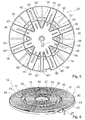
- Fig. 6
- den Spulenträger mit aufgewickelten inneren und äußeren Spulenabschnitten in einer perspektivischen Ansicht von oben,
- Fig. 7
- den Spulenträger mit aufgewickelten inneren und äußeren Spulenabschnitten in einer Ansicht von unten, wobei ein Teil einer Bündelungseinheit montiert wird und
- Fig. 8
- den Spulenträger mit fertig montierter Induktionsheizleitung und fertig montierter Bündelungseinheit.
- Fig. 1
- an inventive hob in a schematic view from above,
- Fig. 2
- a first sub-carrier of a bobbin carrier,
- Fig. 3
- an inner coil section wound on the first sub-carrier,
- Fig. 4
- a second sub-carrier of a bobbin, which is attached to the first sub-carrier,
- Fig. 5
- the assembled sub-carriers of the bobbin in a view from below,
- Fig. 6
- the bobbin with wound inner and outer coil sections in a perspective view from above,
- Fig. 7
- the bobbin with wound inner and outer coil sections in a view from below, wherein a part of a bundling unit is mounted and
- Fig. 8
- the bobbin with fully assembled induction heating cable and fully assembled bundling unit.
Die
Der erste Teilträger 30 ist von einem Kunststoff gebildet. Der erste Teilträger 30 weist eine Trägerfläche 34 auf, die senkrecht zu dem inneren Trägerkern 31 ausgerichtet ist. Die Trägerfläche 34 wird von speichenartig von einem Zentrum des ersten Teilträgers 30 ausgehenden Ausformungen 35, 35', 35" gebildet. Die Ausformungen 35, 35', 35" weisen unterschiedliche Längen auf. Die Ausformungen 35, 35', 35' weisen jeweils auf einer der Trägerfläche 34 abgewandten Seite ein U-Profil auf. Der erste Teilträger 30 weist acht Ausformungen 35, 35' auf, die in einem fertig montierten Zustand Bündelungselemente 24 einer Bündelungseinheit 22 aufnehmen (
Der zweite Teilträger 40 ist von einem gleichen Kunststoff gebildet, wie der erste Teilträger 30. Der zweite Teilträger 40 weist eine Trägerfläche 44 auf. Die Trägerfläche 44 ist von den Oberseiten von speichenartigen Ausformungen 45, 45', 45" gebildet. Die Ausformungen 45, 45', 45" weisen jeweils ein U-Profil auf. Die Ausformungen 45, 45', 45" sind an einer radialen Außenseite über einen hohlzylinderartigen Ring 47 miteinander verbunden. In Zwischenräumen zwischen den Ausformungen 45, 45', 45" an radialen Innenseiten der Ausformungen 45, 45', 45" sind Ringabschnitte 48 angeordnet, die die Ausformungen 45, 45', 45" miteinander verbinden. Vier der Ausformungen 45' des zweiten Teilträgers 40 weisen an ihrer Innenseite als Einschnitte ausgebildete Formschlussmittel auf, in die die längeren Ausformungen 35' des ersten Teilträgers 30 eingreifen. In einem montierten Zustand sind die Teilträger 30, 40 in Umfangsrichtung durch die Ausgestaltung der speichenartigen Ausformungen 35, 35', 45, 45' formschlüssig miteinander verbunden.The
Weiterhin weist der zweite Teilträger 40 Verstärkungsstreben 49 auf, die radial von Mitten der Ringabschnitte 48 ausgehend bis zu dem Ring 47 reichen und zwischen den Ausformungen 45, 45' angeordnet sind. Der innere Trägerkern 41 sorgt für ein zusätzliche Verbindung und Verstärkung der Ausformungen 45, 45', 45" miteinander und den Verstärkungsstreben 49. Der zweite Teilträger 40 weist acht Ausformungen 45, 45' auf, die in einem fertig montierten Zustand Bündelungselemente 24 der Bündelungseinheit 22 aufnehmen (
In den speichenförmigen Ausformungen 35, 35', 45, 45' sind jeweils Langlöcher 36, 46 angeordnet. Die Langlöcher 36, 46 erstrecken sich jeweils in radialer Richtung. Die Langlöcher 36, 46 weisen jeweils unterschiedliche Längen und Abstände zu einem Zentrum des Spulenträgers 20 auf. Langlöcher 36, 46 unterschiedlicher Teilträger 30, 40 sind teilweise so ausgebildet, dass sie sich gegenseitig fortsetzen. Der innere Spulenabschnitt 18 ist durch diese Langlöcher 36 von unten her abschnittsweise mittels eines als Silikonkleber ausgebildeten Klebstoffs 21 an dem ersten Teilträger 30 und somit dem Spulenträger 20 fixiert (
Bei einer Herstellung der Hausgeräteinduktionsheizvorrichtung 12 wird der erste Teilträger 30 mittels Befestigungspunkten 37 mit einer Rotationsvorrichtung verbunden. Die Induktionsheizleitung 16 wird durch die Eintrittsöffnung 32 des inneren Trägerkerns 31 geführt, wobei ein inneres Ende der Induktionsheizleitung 16 innerhalb eines von dem inneren Trägerkern 31 umgebenen Teilbereichs vorübergehend angeordnet wird. Durch eine Rotation der Rotationsvorrichtung wird nun der erste Teilträger 30 in eine Rotationsbewegung versetzt und die Induktionsheizleitung 16 wickelt sich um den inneren Trägerkern 31 auf. Nach einer vorbestimmten Anzahl an Windungen wird eine Drehbewegung gestoppt. Anschließend wird der zweite Teilträger 40 an den ersten Teilträger 30 angesetzt. Hierbei wird auf eine korrekte Ausrichtung der speichenartigen Ausformungen 35, 35', 45, 45', vor allem der weiteren Ausformungen 35", 45", die die Induktionsheizleitung 16 zum Zentrum des Spulenträgers 20 führen, geachtet. Die Induktionsheizleitung 16 wird durch die Eintrittsöffnung 42 des äußeren Trägerkerns 41 geführt. Anschließend wird der Spulenträger 20 erneut in Rotation versetzt, wodurch sich die Induktionsheizleitung 16 auf den zweiten Teilträger 40, um den äußeren Trägerkern 41 aufwickelt. Die Induktionsheizleitung 16 wird mittels einer am Rand des zweiten Teilträgers 40 angeordneten Klemmstelle 27 fixiert. Die Klemmstelle 27 dient gleichzeitig als Zugentlastung für die Induktionsheizleitung 16.In a production of the household appliance
Anschließend wird in die Langlöcher 36, 46 von einer der Induktionsheizleitung 16 abgewandten Seite des Spulenträgers 20 her als Silikonkleber ausgebildeter Klebstoff 21 eingebracht und die Bündelungselemente 24 werden in die Ausformungen 35, 35', 45, 45' eingeklebt. Die Bündelungselemente 24 erstrecken sich jeweils von einer äußersten bis zu einer innersten Windung der Induktionsheizleitung 16. Anschließend wird das vorrübergehend im Inneren des inneren Trägerkerns 31 angeordnete Ende der Induktionsheizleitung 16 durch das Loch 39 geführt und an einer Unterseite des Spulenträgers 20 in den weiteren Ausformungen 35", 45" zu einem äußeren Rand des Spulenträgers 20 geführt. An einem inneren Ende der weiteren Ausformung 45" des zweiten Teilträgers 40 ist eine Sperrwand 28 angeordnet (
Der Spulenträger 20 weist eine Sensoraufnahme 38 auf. Die Sensoraufnahme 38 ist in einer Mitte des ersten Teilträgers 30 angeordnet und ist dazu vorgesehen, einen Temperatursensor aufzunehmen. Nach Montage des Temperatursensors wird eine elektrische Verbindung des Sensors ebenfalls über die weiteren Ausformungen 35", 45" nach außen geführt.The
In alternativen Ausgestaltungen der Erfindung ist es denkbar, dass ein einstückiger Spulenträger zum Einsatz kommt. Ebenso ist es denkbar, dass unterschiedliche Teilträger jeweils mit separaten Bündelungselementen ausgestattet sind. Insbesondere bei sehr großen Hausgeräteinduktionsheizvorrichtungen ist es denkbar, dass ein Spulenträger von mehr als zwei, insbesondere drei oder gar vier Teilträgern gebildet ist und eine Induktionsheizleitung vorteilhaft ebenso viele Spulenabschnitte aufweist, die jeweils auf einem der Teilträger angeordnet sind. Weiterhin ist es denkbar, dass eine Induktionsheizleitung zu einer rechteckigen oder ovalen Form gewunden ist, wobei eine entsprechende Anpassung einer Form des Spulenträgers und/oder der Teilträger stattfindet. Ferner ist es denkbar, dass die Wicklung der Induktionsheizleitung von Hand statt mit einer Rotationsvorrichtung durchgeführt wird. Weiterhin ist es denkbar, dass Teilträger bei einem Ansetzen aneinander fest miteinander verbunden werden.In alternative embodiments of the invention, it is conceivable that a one-piece coil carrier is used. It is also conceivable that different sub-carriers are each equipped with separate bundling elements. Particularly in the case of very large home appliance induction heaters, it is conceivable for a coil carrier to be formed by more than two, in particular three or even four, partial carriers, and an induction heating line advantageously has just as many coil sections which are each arranged on one of the partial carriers. Furthermore, it is conceivable that an induction heating cable is wound into a rectangular or oval shape, with a corresponding adaptation of a shape of the coil carrier and / or the sub-carrier takes place. Furthermore, it is conceivable that the winding of the induction heating is carried out by hand instead of with a rotary device. Furthermore, it is conceivable that sub-carriers are firmly connected to each other when attached to each other.
- 1010
- Hausgeräthousehold appliance
- 1212
- HausgeräteinduktionsheizvorrichtungHausgeräteinduktionsheizvorrichtung
- 1414
- KochfeldplatteHotplate
- 1616
- InduktionsheizleitungInduktionsheizleitung
- 1818
- Spulenabschnittcoil section
- 1919
- Spulenabschnittcoil section
- 2020
- Spulenträgercoil carrier
- 2121
- Klebstoffadhesive
- 2222
- Bündelungseinheitbuncher
- 2424
- Bündelungselementbundling element
- 2727
- Klemmstellenip
- 2828
- Sperrwandbarrier wall
- 3030
- Teilträgersubcarrier
- 3131
- Trägerkerncarrier core
- 3232
- Eintrittsöffnunginlet opening
- 3434
- Trägerflächesupport surface
- 3535
- Ausformungformation
- 3636
- LanglochLong hole
- 3737
- Befestigungspunktattachment point
- 3838
- Sensoraufnahmesensor recording
- 3939
- Lochhole
- 4040
- Teilträgersubcarrier
- 4141
- Trägerkerncarrier core
- 4242
- Eintrittsöffnunginlet opening
- 4343
- Unterbrechunginterruption
- 4444
- Trägerflächesupport surface
- 4545
- Ausformungformation
- 4646
- LanglochLong hole
- 4747
- Ringring
- 4848
- Ringabschnittring section
- 4949
- Verstärkungsstrebereinforcing strut
Claims (11)
Applications Claiming Priority (1)
| Application Number | Priority Date | Filing Date | Title |
|---|---|---|---|
| ES201330228 | 2013-02-20 |
Publications (2)
| Publication Number | Publication Date |
|---|---|
| EP2770801A1 true EP2770801A1 (en) | 2014-08-27 |
| EP2770801B1 EP2770801B1 (en) | 2017-04-12 |
Family
ID=50068866
Family Applications (1)
| Application Number | Title | Priority Date | Filing Date |
|---|---|---|---|
| EP14154170.6A Active EP2770801B1 (en) | 2013-02-20 | 2014-02-06 | Induction heating device for household appliances |
Country Status (2)
| Country | Link |
|---|---|
| EP (1) | EP2770801B1 (en) |
| ES (1) | ES2627155T3 (en) |
Cited By (6)
| Publication number | Priority date | Publication date | Assignee | Title |
|---|---|---|---|---|
| WO2016124526A1 (en) * | 2015-02-05 | 2016-08-11 | Würth Elektronik eiSos Gmbh & Co. KG | Inductor, in particular for magnetically coupled energy transfer, as well as method for operating an inductor of this type |
| EP3340738A1 (en) * | 2016-12-22 | 2018-06-27 | Whirlpool Corporation | Induction burner element having a plurality of single piece frames |
| CN109156051A (en) * | 2016-05-30 | 2019-01-04 | 美食之燃有限公司 | induction furnace |
| EP3450856A1 (en) * | 2017-09-01 | 2019-03-06 | Panasonic Intellectual Property Management Co., Ltd. | Induction heating cooker |
| EP3468301A4 (en) * | 2016-06-07 | 2020-01-29 | LG Electronics Inc. | Induction heating device |
| EP4329429A1 (en) * | 2022-08-25 | 2024-02-28 | Peaceworld.Co., Ltd | Base-plate structure having good heat dissipation function of heating coil |
Families Citing this family (1)
| Publication number | Priority date | Publication date | Assignee | Title |
|---|---|---|---|---|
| KR20220072207A (en) * | 2020-11-25 | 2022-06-02 | 엘지전자 주식회사 | Electric range |
Citations (5)
| Publication number | Priority date | Publication date | Assignee | Title |
|---|---|---|---|---|
| US4947464A (en) * | 1985-12-07 | 1990-08-07 | Sumitomo Electric Industries, Ltd. | Heating coil assembly for an electromagnetic induction cooking assembly |
| JP2003197358A (en) * | 2001-12-25 | 2003-07-11 | Matsushita Electric Ind Co Ltd | Induction heating cooker |
| JP2005302406A (en) * | 2004-04-08 | 2005-10-27 | Hitachi Home & Life Solutions Inc | Induction heating cooker |
| DE102005005527A1 (en) * | 2005-01-31 | 2006-08-03 | E.G.O. Elektro-Gerätebau GmbH | Induction heating device for cooking area of hob tray, has supply part converting applied voltage into power control for induction coil, where device is formed as installation-finished and/or connection-finished component |
| WO2012108136A1 (en) * | 2011-02-10 | 2012-08-16 | 三菱電機株式会社 | Induction heating cooker |
-
2014
- 2014-02-06 EP EP14154170.6A patent/EP2770801B1/en active Active
- 2014-02-06 ES ES14154170.6T patent/ES2627155T3/en active Active
Patent Citations (5)
| Publication number | Priority date | Publication date | Assignee | Title |
|---|---|---|---|---|
| US4947464A (en) * | 1985-12-07 | 1990-08-07 | Sumitomo Electric Industries, Ltd. | Heating coil assembly for an electromagnetic induction cooking assembly |
| JP2003197358A (en) * | 2001-12-25 | 2003-07-11 | Matsushita Electric Ind Co Ltd | Induction heating cooker |
| JP2005302406A (en) * | 2004-04-08 | 2005-10-27 | Hitachi Home & Life Solutions Inc | Induction heating cooker |
| DE102005005527A1 (en) * | 2005-01-31 | 2006-08-03 | E.G.O. Elektro-Gerätebau GmbH | Induction heating device for cooking area of hob tray, has supply part converting applied voltage into power control for induction coil, where device is formed as installation-finished and/or connection-finished component |
| WO2012108136A1 (en) * | 2011-02-10 | 2012-08-16 | 三菱電機株式会社 | Induction heating cooker |
Cited By (11)
| Publication number | Priority date | Publication date | Assignee | Title |
|---|---|---|---|---|
| WO2016124526A1 (en) * | 2015-02-05 | 2016-08-11 | Würth Elektronik eiSos Gmbh & Co. KG | Inductor, in particular for magnetically coupled energy transfer, as well as method for operating an inductor of this type |
| US10541080B2 (en) | 2015-02-05 | 2020-01-21 | Würth Elektronik eiSos Gmbh & Co. KG | Inductor, in particular for magnetically coupled energy transfer, as well as method for operating an inductor of this type |
| CN109156051A (en) * | 2016-05-30 | 2019-01-04 | 美食之燃有限公司 | induction furnace |
| EP3468301A4 (en) * | 2016-06-07 | 2020-01-29 | LG Electronics Inc. | Induction heating device |
| US11166347B2 (en) | 2016-06-07 | 2021-11-02 | Lg Electronics Inc. | Induction heating device |
| EP3340738A1 (en) * | 2016-12-22 | 2018-06-27 | Whirlpool Corporation | Induction burner element having a plurality of single piece frames |
| US20180184489A1 (en) * | 2016-12-22 | 2018-06-28 | Whirlpool Corporation | Induction burner element having a plurality of single piece frames |
| EP3340738B1 (en) | 2016-12-22 | 2020-03-25 | Whirlpool Corporation | Induction burner element having a plurality of single piece frames |
| US11665790B2 (en) | 2016-12-22 | 2023-05-30 | Whirlpool Corporation | Induction burner element having a plurality of single piece frames |
| EP3450856A1 (en) * | 2017-09-01 | 2019-03-06 | Panasonic Intellectual Property Management Co., Ltd. | Induction heating cooker |
| EP4329429A1 (en) * | 2022-08-25 | 2024-02-28 | Peaceworld.Co., Ltd | Base-plate structure having good heat dissipation function of heating coil |
Also Published As
| Publication number | Publication date |
|---|---|
| ES2627155T3 (en) | 2017-07-26 |
| EP2770801B1 (en) | 2017-04-12 |
Similar Documents
| Publication | Publication Date | Title |
|---|---|---|
| EP2770801B1 (en) | Induction heating device for household appliances | |
| EP2838315B1 (en) | Induction heating unit | |
| EP3130197B1 (en) | Inductance, especially for transmission of energy via magnetic coupling, and method to control such an inductance | |
| EP2642636B1 (en) | Hollow cylinder iron-free coil | |
| DE3741909C2 (en) | Electric induction heating with reduced harmonic emission | |
| WO2014121897A2 (en) | Device having a winding arrangement and arrangement, in particular a charging station, for contactless transfer of energy to an electric vehicle, having a winding arrangement | |
| DE102013218714A1 (en) | Cooking field device i.e. induction cooking field device, has spring elements pressing heating units against cooking field plate and in detent connection with assembly strips, which connect cooking field housing unit with field plate | |
| DE10343011A1 (en) | Device for heating food by induction and device for the transmission of energy | |
| WO2011015491A1 (en) | Current compensated inductor and method for producing a current compensated inductor | |
| DE102011083128A1 (en) | electric motor | |
| DE102015220788A1 (en) | Hob device and method of assembling a Hob device | |
| EP3692555A1 (en) | System for non-contact transmission of electrical energy to a mobile part | |
| EP2592899A2 (en) | Domestic appliance | |
| EP3030044B1 (en) | Hotplate device | |
| EP2973622A1 (en) | Winding arrangement having partial windings, and arrangement, in particular charging station, for contactless energy transmission to an electric vehicle, having a winding arrangement | |
| DE69333119T2 (en) | Signal separation device with coil construction | |
| EP2786637B1 (en) | Induction heating apparatus | |
| DE102013214434A1 (en) | Induction heating device of cooking apparatus, has induction heating units that are provided with induction heating pipelines having two strip conductors which are formed on two different printed circuit boards | |
| WO2018116064A1 (en) | Cooking appliance apparatus, and method for producing a cooking appliance apparatus | |
| DE102014001185A1 (en) | Magnetic field application with slotted laminated core for magnetic stimulation of body tissue | |
| EP1683394B1 (en) | Inductor comprising a litz wire that is rolled up so as to form a spiral-shaped induction coil | |
| DE102022205386A1 (en) | Induction hob with a support structure with antennas and/or sensors, method for producing such a support structure and a use of a support structure for an induction hob | |
| WO2005018282A1 (en) | Device for heating food using induction and device for transmitting energy | |
| DE2850190A1 (en) | High dielectric strength HV transformer - uses inter-connecting combs to form half-shells for accommodating coil bobbins | |
| DE102018214486A1 (en) | Induction hob device |
Legal Events
| Date | Code | Title | Description |
|---|---|---|---|
| PUAI | Public reference made under article 153(3) epc to a published international application that has entered the european phase |
Free format text: ORIGINAL CODE: 0009012 |
|
| 17P | Request for examination filed |
Effective date: 20140206 |
|
| AK | Designated contracting states |
Kind code of ref document: A1 Designated state(s): AL AT BE BG CH CY CZ DE DK EE ES FI FR GB GR HR HU IE IS IT LI LT LU LV MC MK MT NL NO PL PT RO RS SE SI SK SM TR |
|
| AX | Request for extension of the european patent |
Extension state: BA ME |
|
| RAP1 | Party data changed (applicant data changed or rights of an application transferred) |
Owner name: BSH HAUSGERAETE GMBH |
|
| R17P | Request for examination filed (corrected) |
Effective date: 20150227 |
|
| RBV | Designated contracting states (corrected) |
Designated state(s): AL AT BE BG CH CY CZ DE DK EE ES FI FR GB GR HR HU IE IS IT LI LT LU LV MC MK MT NL NO PL PT RO RS SE SI SK SM TR |
|
| GRAP | Despatch of communication of intention to grant a patent |
Free format text: ORIGINAL CODE: EPIDOSNIGR1 |
|
| RIC1 | Information provided on ipc code assigned before grant |
Ipc: H05B 6/12 20060101AFI20161017BHEP |
|
| INTG | Intention to grant announced |
Effective date: 20161108 |
|
| GRAS | Grant fee paid |
Free format text: ORIGINAL CODE: EPIDOSNIGR3 |
|
| GRAA | (expected) grant |
Free format text: ORIGINAL CODE: 0009210 |
|
| AK | Designated contracting states |
Kind code of ref document: B1 Designated state(s): AL AT BE BG CH CY CZ DE DK EE ES FI FR GB GR HR HU IE IS IT LI LT LU LV MC MK MT NL NO PL PT RO RS SE SI SK SM TR |
|
| REG | Reference to a national code |
Ref country code: GB Ref legal event code: FG4D Free format text: NOT ENGLISH |
|
| REG | Reference to a national code |
Ref country code: CH Ref legal event code: EP |
|
| REG | Reference to a national code |
Ref country code: IE Ref legal event code: FG4D Free format text: LANGUAGE OF EP DOCUMENT: GERMAN |
|
| REG | Reference to a national code |
Ref country code: AT Ref legal event code: REF Ref document number: 884965 Country of ref document: AT Kind code of ref document: T Effective date: 20170515 |
|
| REG | Reference to a national code |
Ref country code: DE Ref legal event code: R096 Ref document number: 502014003343 Country of ref document: DE |
|
| REG | Reference to a national code |
Ref country code: ES Ref legal event code: FG2A Ref document number: 2627155 Country of ref document: ES Kind code of ref document: T3 Effective date: 20170726 |
|
| REG | Reference to a national code |
Ref country code: NL Ref legal event code: MP Effective date: 20170412 |
|
| REG | Reference to a national code |
Ref country code: LT Ref legal event code: MG4D |
|
| PG25 | Lapsed in a contracting state [announced via postgrant information from national office to epo] |
Ref country code: NL Free format text: LAPSE BECAUSE OF FAILURE TO SUBMIT A TRANSLATION OF THE DESCRIPTION OR TO PAY THE FEE WITHIN THE PRESCRIBED TIME-LIMIT Effective date: 20170412 |
|
| PG25 | Lapsed in a contracting state [announced via postgrant information from national office to epo] |
Ref country code: GR Free format text: LAPSE BECAUSE OF FAILURE TO SUBMIT A TRANSLATION OF THE DESCRIPTION OR TO PAY THE FEE WITHIN THE PRESCRIBED TIME-LIMIT Effective date: 20170713 Ref country code: NO Free format text: LAPSE BECAUSE OF FAILURE TO SUBMIT A TRANSLATION OF THE DESCRIPTION OR TO PAY THE FEE WITHIN THE PRESCRIBED TIME-LIMIT Effective date: 20170712 Ref country code: HR Free format text: LAPSE BECAUSE OF FAILURE TO SUBMIT A TRANSLATION OF THE DESCRIPTION OR TO PAY THE FEE WITHIN THE PRESCRIBED TIME-LIMIT Effective date: 20170412 Ref country code: FI Free format text: LAPSE BECAUSE OF FAILURE TO SUBMIT A TRANSLATION OF THE DESCRIPTION OR TO PAY THE FEE WITHIN THE PRESCRIBED TIME-LIMIT Effective date: 20170412 Ref country code: LT Free format text: LAPSE BECAUSE OF FAILURE TO SUBMIT A TRANSLATION OF THE DESCRIPTION OR TO PAY THE FEE WITHIN THE PRESCRIBED TIME-LIMIT Effective date: 20170412 |
|
| PG25 | Lapsed in a contracting state [announced via postgrant information from national office to epo] |
Ref country code: IS Free format text: LAPSE BECAUSE OF FAILURE TO SUBMIT A TRANSLATION OF THE DESCRIPTION OR TO PAY THE FEE WITHIN THE PRESCRIBED TIME-LIMIT Effective date: 20170812 Ref country code: PL Free format text: LAPSE BECAUSE OF FAILURE TO SUBMIT A TRANSLATION OF THE DESCRIPTION OR TO PAY THE FEE WITHIN THE PRESCRIBED TIME-LIMIT Effective date: 20170412 Ref country code: BG Free format text: LAPSE BECAUSE OF FAILURE TO SUBMIT A TRANSLATION OF THE DESCRIPTION OR TO PAY THE FEE WITHIN THE PRESCRIBED TIME-LIMIT Effective date: 20170712 Ref country code: SE Free format text: LAPSE BECAUSE OF FAILURE TO SUBMIT A TRANSLATION OF THE DESCRIPTION OR TO PAY THE FEE WITHIN THE PRESCRIBED TIME-LIMIT Effective date: 20170412 Ref country code: RS Free format text: LAPSE BECAUSE OF FAILURE TO SUBMIT A TRANSLATION OF THE DESCRIPTION OR TO PAY THE FEE WITHIN THE PRESCRIBED TIME-LIMIT Effective date: 20170412 Ref country code: LV Free format text: LAPSE BECAUSE OF FAILURE TO SUBMIT A TRANSLATION OF THE DESCRIPTION OR TO PAY THE FEE WITHIN THE PRESCRIBED TIME-LIMIT Effective date: 20170412 |
|
| REG | Reference to a national code |
Ref country code: DE Ref legal event code: R097 Ref document number: 502014003343 Country of ref document: DE |
|
| PG25 | Lapsed in a contracting state [announced via postgrant information from national office to epo] |
Ref country code: RO Free format text: LAPSE BECAUSE OF FAILURE TO SUBMIT A TRANSLATION OF THE DESCRIPTION OR TO PAY THE FEE WITHIN THE PRESCRIBED TIME-LIMIT Effective date: 20170412 Ref country code: EE Free format text: LAPSE BECAUSE OF FAILURE TO SUBMIT A TRANSLATION OF THE DESCRIPTION OR TO PAY THE FEE WITHIN THE PRESCRIBED TIME-LIMIT Effective date: 20170412 Ref country code: CZ Free format text: LAPSE BECAUSE OF FAILURE TO SUBMIT A TRANSLATION OF THE DESCRIPTION OR TO PAY THE FEE WITHIN THE PRESCRIBED TIME-LIMIT Effective date: 20170412 Ref country code: SK Free format text: LAPSE BECAUSE OF FAILURE TO SUBMIT A TRANSLATION OF THE DESCRIPTION OR TO PAY THE FEE WITHIN THE PRESCRIBED TIME-LIMIT Effective date: 20170412 Ref country code: DK Free format text: LAPSE BECAUSE OF FAILURE TO SUBMIT A TRANSLATION OF THE DESCRIPTION OR TO PAY THE FEE WITHIN THE PRESCRIBED TIME-LIMIT Effective date: 20170412 |
|
| PLBE | No opposition filed within time limit |
Free format text: ORIGINAL CODE: 0009261 |
|
| STAA | Information on the status of an ep patent application or granted ep patent |
Free format text: STATUS: NO OPPOSITION FILED WITHIN TIME LIMIT |
|
| REG | Reference to a national code |
Ref country code: FR Ref legal event code: PLFP Year of fee payment: 5 |
|
| PG25 | Lapsed in a contracting state [announced via postgrant information from national office to epo] |
Ref country code: SM Free format text: LAPSE BECAUSE OF FAILURE TO SUBMIT A TRANSLATION OF THE DESCRIPTION OR TO PAY THE FEE WITHIN THE PRESCRIBED TIME-LIMIT Effective date: 20170412 |
|
| 26N | No opposition filed |
Effective date: 20180115 |
|
| PG25 | Lapsed in a contracting state [announced via postgrant information from national office to epo] |
Ref country code: SI Free format text: LAPSE BECAUSE OF FAILURE TO SUBMIT A TRANSLATION OF THE DESCRIPTION OR TO PAY THE FEE WITHIN THE PRESCRIBED TIME-LIMIT Effective date: 20170412 |
|
| REG | Reference to a national code |
Ref country code: CH Ref legal event code: PL |
|
| PG25 | Lapsed in a contracting state [announced via postgrant information from national office to epo] |
Ref country code: MT Free format text: LAPSE BECAUSE OF FAILURE TO SUBMIT A TRANSLATION OF THE DESCRIPTION OR TO PAY THE FEE WITHIN THE PRESCRIBED TIME-LIMIT Effective date: 20170412 Ref country code: MC Free format text: LAPSE BECAUSE OF FAILURE TO SUBMIT A TRANSLATION OF THE DESCRIPTION OR TO PAY THE FEE WITHIN THE PRESCRIBED TIME-LIMIT Effective date: 20170412 |
|
| REG | Reference to a national code |
Ref country code: IE Ref legal event code: MM4A |
|
| REG | Reference to a national code |
Ref country code: BE Ref legal event code: MM Effective date: 20180228 |
|
| PG25 | Lapsed in a contracting state [announced via postgrant information from national office to epo] |
Ref country code: LI Free format text: LAPSE BECAUSE OF NON-PAYMENT OF DUE FEES Effective date: 20180228 Ref country code: CH Free format text: LAPSE BECAUSE OF NON-PAYMENT OF DUE FEES Effective date: 20180228 Ref country code: LU Free format text: LAPSE BECAUSE OF NON-PAYMENT OF DUE FEES Effective date: 20180206 |
|
| PG25 | Lapsed in a contracting state [announced via postgrant information from national office to epo] |
Ref country code: IE Free format text: LAPSE BECAUSE OF NON-PAYMENT OF DUE FEES Effective date: 20180206 |
|
| PG25 | Lapsed in a contracting state [announced via postgrant information from national office to epo] |
Ref country code: BE Free format text: LAPSE BECAUSE OF NON-PAYMENT OF DUE FEES Effective date: 20180228 |
|
| PG25 | Lapsed in a contracting state [announced via postgrant information from national office to epo] |
Ref country code: TR Free format text: LAPSE BECAUSE OF FAILURE TO SUBMIT A TRANSLATION OF THE DESCRIPTION OR TO PAY THE FEE WITHIN THE PRESCRIBED TIME-LIMIT Effective date: 20170412 |
|
| REG | Reference to a national code |
Ref country code: AT Ref legal event code: MM01 Ref document number: 884965 Country of ref document: AT Kind code of ref document: T Effective date: 20190206 |
|
| PG25 | Lapsed in a contracting state [announced via postgrant information from national office to epo] |
Ref country code: AT Free format text: LAPSE BECAUSE OF NON-PAYMENT OF DUE FEES Effective date: 20190206 |
|
| PG25 | Lapsed in a contracting state [announced via postgrant information from national office to epo] |
Ref country code: HU Free format text: LAPSE BECAUSE OF FAILURE TO SUBMIT A TRANSLATION OF THE DESCRIPTION OR TO PAY THE FEE WITHIN THE PRESCRIBED TIME-LIMIT; INVALID AB INITIO Effective date: 20140206 Ref country code: PT Free format text: LAPSE BECAUSE OF FAILURE TO SUBMIT A TRANSLATION OF THE DESCRIPTION OR TO PAY THE FEE WITHIN THE PRESCRIBED TIME-LIMIT Effective date: 20170412 |
|
| PG25 | Lapsed in a contracting state [announced via postgrant information from national office to epo] |
Ref country code: MK Free format text: LAPSE BECAUSE OF NON-PAYMENT OF DUE FEES Effective date: 20170412 Ref country code: CY Free format text: LAPSE BECAUSE OF FAILURE TO SUBMIT A TRANSLATION OF THE DESCRIPTION OR TO PAY THE FEE WITHIN THE PRESCRIBED TIME-LIMIT Effective date: 20170412 |
|
| PG25 | Lapsed in a contracting state [announced via postgrant information from national office to epo] |
Ref country code: AL Free format text: LAPSE BECAUSE OF FAILURE TO SUBMIT A TRANSLATION OF THE DESCRIPTION OR TO PAY THE FEE WITHIN THE PRESCRIBED TIME-LIMIT Effective date: 20170412 |
|
| PGFP | Annual fee paid to national office [announced via postgrant information from national office to epo] |
Ref country code: FR Payment date: 20230217 Year of fee payment: 10 Ref country code: ES Payment date: 20230317 Year of fee payment: 10 |
|
| PGFP | Annual fee paid to national office [announced via postgrant information from national office to epo] |
Ref country code: IT Payment date: 20230228 Year of fee payment: 10 Ref country code: GB Payment date: 20230221 Year of fee payment: 10 Ref country code: DE Payment date: 20230228 Year of fee payment: 10 |
|
| PGFP | Annual fee paid to national office [announced via postgrant information from national office to epo] |
Ref country code: ES Payment date: 20240319 Year of fee payment: 11 |