EP2769876A1 - Motor car chair for a child - Google Patents
Motor car chair for a child Download PDFInfo
- Publication number
- EP2769876A1 EP2769876A1 EP20130460050 EP13460050A EP2769876A1 EP 2769876 A1 EP2769876 A1 EP 2769876A1 EP 20130460050 EP20130460050 EP 20130460050 EP 13460050 A EP13460050 A EP 13460050A EP 2769876 A1 EP2769876 A1 EP 2769876A1
- Authority
- EP
- European Patent Office
- Prior art keywords
- chair
- bottom seat
- base
- child
- seat
- Prior art date
- Legal status (The legal status is an assumption and is not a legal conclusion. Google has not performed a legal analysis and makes no representation as to the accuracy of the status listed.)
- Granted
Links
- 210000000078 claw Anatomy 0.000 claims description 3
- 238000004873 anchoring Methods 0.000 description 11
- 230000008878 coupling Effects 0.000 description 8
- 238000010168 coupling process Methods 0.000 description 8
- 238000005859 coupling reaction Methods 0.000 description 8
- 229920006328 Styrofoam Polymers 0.000 description 1
- 239000000463 material Substances 0.000 description 1
- 238000012986 modification Methods 0.000 description 1
- 230000004048 modification Effects 0.000 description 1
- 230000002787 reinforcement Effects 0.000 description 1
- 239000008261 styrofoam Substances 0.000 description 1
Images


Classifications
-
- B—PERFORMING OPERATIONS; TRANSPORTING
- B60—VEHICLES IN GENERAL
- B60N—SEATS SPECIALLY ADAPTED FOR VEHICLES; VEHICLE PASSENGER ACCOMMODATION NOT OTHERWISE PROVIDED FOR
- B60N2/00—Seats specially adapted for vehicles; Arrangement or mounting of seats in vehicles
- B60N2/24—Seats specially adapted for vehicles; Arrangement or mounting of seats in vehicles for particular purposes or particular vehicles
- B60N2/26—Seats specially adapted for vehicles; Arrangement or mounting of seats in vehicles for particular purposes or particular vehicles for children
- B60N2/28—Seats readily mountable on, and dismountable from, existing seats or other parts of the vehicle
- B60N2/2803—Adaptations for seat belts
- B60N2/2806—Adaptations for seat belts for securing the child seat to the vehicle
-
- B—PERFORMING OPERATIONS; TRANSPORTING
- B60—VEHICLES IN GENERAL
- B60N—SEATS SPECIALLY ADAPTED FOR VEHICLES; VEHICLE PASSENGER ACCOMMODATION NOT OTHERWISE PROVIDED FOR
- B60N2/00—Seats specially adapted for vehicles; Arrangement or mounting of seats in vehicles
- B60N2/24—Seats specially adapted for vehicles; Arrangement or mounting of seats in vehicles for particular purposes or particular vehicles
- B60N2/26—Seats specially adapted for vehicles; Arrangement or mounting of seats in vehicles for particular purposes or particular vehicles for children
- B60N2/28—Seats readily mountable on, and dismountable from, existing seats or other parts of the vehicle
- B60N2/2803—Adaptations for seat belts
- B60N2/2812—Adaptations for seat belts for securing the child to the child seat
-
- B—PERFORMING OPERATIONS; TRANSPORTING
- B60—VEHICLES IN GENERAL
- B60N—SEATS SPECIALLY ADAPTED FOR VEHICLES; VEHICLE PASSENGER ACCOMMODATION NOT OTHERWISE PROVIDED FOR
- B60N2/00—Seats specially adapted for vehicles; Arrangement or mounting of seats in vehicles
- B60N2/24—Seats specially adapted for vehicles; Arrangement or mounting of seats in vehicles for particular purposes or particular vehicles
- B60N2/26—Seats specially adapted for vehicles; Arrangement or mounting of seats in vehicles for particular purposes or particular vehicles for children
- B60N2/28—Seats readily mountable on, and dismountable from, existing seats or other parts of the vehicle
- B60N2/2821—Seats readily mountable on, and dismountable from, existing seats or other parts of the vehicle having a seat and a base part
-
- B—PERFORMING OPERATIONS; TRANSPORTING
- B60—VEHICLES IN GENERAL
- B60N—SEATS SPECIALLY ADAPTED FOR VEHICLES; VEHICLE PASSENGER ACCOMMODATION NOT OTHERWISE PROVIDED FOR
- B60N2/00—Seats specially adapted for vehicles; Arrangement or mounting of seats in vehicles
- B60N2/24—Seats specially adapted for vehicles; Arrangement or mounting of seats in vehicles for particular purposes or particular vehicles
- B60N2/26—Seats specially adapted for vehicles; Arrangement or mounting of seats in vehicles for particular purposes or particular vehicles for children
- B60N2/28—Seats readily mountable on, and dismountable from, existing seats or other parts of the vehicle
- B60N2/2884—Seats readily mountable on, and dismountable from, existing seats or other parts of the vehicle with protection systems against abnormal g-forces
-
- B—PERFORMING OPERATIONS; TRANSPORTING
- B60—VEHICLES IN GENERAL
- B60N—SEATS SPECIALLY ADAPTED FOR VEHICLES; VEHICLE PASSENGER ACCOMMODATION NOT OTHERWISE PROVIDED FOR
- B60N2/00—Seats specially adapted for vehicles; Arrangement or mounting of seats in vehicles
- B60N2/24—Seats specially adapted for vehicles; Arrangement or mounting of seats in vehicles for particular purposes or particular vehicles
- B60N2/26—Seats specially adapted for vehicles; Arrangement or mounting of seats in vehicles for particular purposes or particular vehicles for children
- B60N2/28—Seats readily mountable on, and dismountable from, existing seats or other parts of the vehicle
- B60N2/2887—Fixation to a transversal anchorage bar, e.g. isofix
Definitions
- the base is fastened on a car seat by means of the isofix system, car seat belts or in some other way.
- the chair shell may be detached from the base and this operation does not require disassembling of the base from the car seat.
- the child is supported in the chair shell by means of internal belts - mounted to the chair shell.
- a motor car chair for a child is known as presented in patent document CA 2558978 .
- the chair comprises: a bottom seat frame with a backrest with a slot for internal seat belts of the chair that limit the seat occupied by a child, a bottom seat frame comprising an energy-absorbing element operationally connected to the slot so as to reduce the amount of force of the internal belt affecting the child occupying the chair during sudden braking.
- several slots are contemplated in the chair frame through which slots the internal belt may be threaded.
- An seat for a child is known to be used in vehicles as presented in patent document EP 1059194 . It comprises a chair body with a first and second side surfaces, where the first abutting surface extends between the side surfaces and is arranged to abut the cushion of the bottom seat of the car seat, while the other abutting surface extends between the side surfaces and is arranged to abut the backrest of the car vehicle seat.
- a motor car chair for a child is known intended for small infants, as presented in patent document EP 1470952 .
- the chair comprises a frame mounted on the bottom seat of a vehicle seat and a rear bracket which may be rotated relative to the frame.
- the seat of the vehicle comprises a part that constitutes a bottom seat and a backrest.
- the lower part of the rear chair bracket positioned at the frame is movable relative to the frame, in the directions towards and from the rear part of the vehicle.
- the rear bracket is upright in a first position where at the lower part of the rear bracket it is located near the rear part of the vehicle and it is inclined in a second position where at the lower part of the rear bracket it is spaced from the rear part of the vehicle.
- a securing frame is known for a motor car seat for a child, as presented in patent document EP 1517810 .
- the frame is provided with anchoring elements connected to the chair and rigidly coupled with the base and/or the bottom seat of the vehicle seat.
- the anchoring elements may be released from the coupling with the anchoring elements of the infant chair affixed to the vehicle by means of links connected together with a transverse bar and the latter is coupled with a pulling handle for detachment.
- a motor car chair is known as presented in patent document FR 2957313 .
- the chair is provided with a footing integrated with a vehicle seat in one mounting position.
- the chair along with a base and backrest takes a front or rear position relative to the footing.
- Pairs of two fastening elements are arranged symmetrically in a manner that one pair of first fastening elements interacts with a second pair of first fastening elements in a position oriented backwards relative to the direction of driving, where the second pair of first fastening elements interacts with the first pair of second fastening elements.
- a system for holding a child in a chair as presented in patent document US 5567008 .
- the system comprises a base mounted to a motor car seat and a carrycot for an infant, comprising a chair shell assembled with the base by means of a clamp arm.
- the clamp arm is movable so as to disengage the shell from the base, and for this purpose a release button mounted on the shell is provided.
- a system for coupling a carrycot for infants to another device that constitutes a base, as presented in patent document US 5772279 .
- the system comprises a carrycot that comprises coupling means extending from a side of the carrycot, and the coupling means form mounting pockets.
- the devices that constitute the base such a pram or a vehicle chair, have coupling posts arranged for the mounting pockets of the carrycot.
- a chair for a child is further known to be mounted on a motor car seat as presented in patent document US 6592183 .
- the chair comprises a first pair of apertures and a second pair of apertures.
- the vehicle anchoring system comprises an anchoring system for coupling a pair of anchoring mounting elements used in the vehicle seat or in the vicinity thereof.
- the vehicle anchoring system comprises a securing belt that has a central part and opposite end parts as well as a fastener coupled with each of the end parts, arranged to couple one of the mounting elements.
- the vehicle anchoring system also comprises a leash coupled with the chair and the central part of the securing belt. The leash remains coupled with the chair and the securing belt, while the securing belt is moved between the first and second aperture of the chair.
- a motor car chair is known as presented in patent document US 6428099 .
- the car vehicle chair for a child is releasably mounted to the base adapted for a motor car seat.
- the chair may be positioned in an upright or inclined position, and additionally it may comprise a compartment for housing small accessories.
- a motor car chair is known as presented in patent document US 6692073 . This is a chair/carrycot for an infant arranged in a motor car so as to enable swinging thereof.
- a motor car chair is known as presented in patent document US 2007176477 .
- This is an infant chair where the harness for holding the infant is fastened relative to the vehicle through a mounting system independent of any chair framework.
- the chair itself is mounted to a motor car seat.
- the harness advantageously, comprises an internal main belt which is looped behind the chair through a pair of slots so as to provide surrounding the infant with two internal shoulder belts. Multiple pairs of slots provide a possibility to change the height of the internal shoulder belts.
- the chair is fastened with the internal belts to the vehicle seat.
- This set has no chair base.
- the chair has an additional internal belt loop that holds the chair.
- a single drawing in element comprises an extendable arm connected with an internal belt of the chair that has at its opposite ends coupling elements to lock anchoring loops.
- a release button on the drawing in element upon being pressed, enables retraction of the arm of the drawing in element when maintaining the coupling elements in the vicinity of the infant chair in a storage position.
- a vehicle chair for a child is mounted on a motor car seat and has a base where clamping catches are positioned, and a shell bottom seat.
- the bottom seat has internal belts for the child, having two shoulder segments extending in the space of the bottom seat intended for the child and passing to the other side of the bottom seat and there connected to a tensioning belt by a tensioner, and in the space of the bottom seat intended for a child it has a connecting crotch element provided with a clamp for internal belts.
- the fastening part of the connecting crotch element is provided with a handle, positioned at the opposite side of the bottom seat relative to the side of the bottom seat intended for a child, and the belt tensioner of the chair is provided with a connector.
- the handle of the fastening element of the connecting crotch element and the tensioner connector are coupled with clamp catches of the chair base, when the bottom seat is seated in the base.
- the chair base is mounted to a motor car seat by means of an isofix system as defined by the applicable international standards and used by numerous manufacturers of automotive vehicles.
- the chair base is mounted to a motor car seat by means of safety belts the motor car is equipped with.
- the connecting crotch element is a belt.
- the clamp catches have claw elements, are rotatable on shafts, and are released by springs, where the tensioner connector and the handle of the fastening element of the crotch belt have a cross-section that cooperates with clamp catches in a circular shape.
- the chair base is provided with longitudinal side channels, where the central part thereof, at the side corresponding to the bottom seat the backrest has a projection of a cylinder-like shape the axis of which extends transversely to the longitudinal axis of the bottom seat, where longitudinal rails of the bottom seat enter channels of the base and the protrusion of the base enters a recess of the bottom seat during positioning the bottom seat in the chair base.
- Fig. 1 shows a motor car chair for a child in exploded side view, which means that a chair base is positioned on a motor car seat with a bottom seat of the chair above before the chair is clamped in the base;
- Fig 2 shows a section of a segment of the chair illustrating fastening of a handle of a connecting crotch element in a clamp catch of the bottom seat;
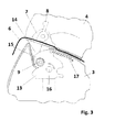
- Fig. 3 shows a section of a chair segment, illustrating fastening of a tensioner connector in a clamp catcher of a bottom seat.
- a motor car chair 1 is intended to be mounted on a car seat 2.
- a chair 1 comprises a base 3 and a bottom seat 4. It is provided with internal belts 5 for a child, where two shoulder segments extend in a bottom seat space 4, intended for a child, and pass to the other side of the bottom seat 4 where they are connected with a tensioning belt 6 threaded through a tensioner 7.
- a handle 12 of a fastening part of a connecting crotch element 10 and a connector 9 of the tensioner 7 are coupled with clamping catches 13 of the base 3 of the chair 1 when the bottom seat 4 is set in the base 3.
- Clamping catches 13 are positioned in recesses of the base 4.
- Clamping catches 13 have claw elements 15 that rotate on shafts 16 and are released by springs 17.
- the tensioner 7 is provided with a lever 8 of the tensioner 7 and the connector 9.
- a connecting crotch element 10 in a form of a belt, provided with a clamp 11 for internal belts 5, and the fastening part of the connecting crotch element 10 is connected to a handle 12, positioned at the opposite side of the bottom seat 4 to the side of the bottom seat 4 intended for a child.
- the handle 12 of the fastening part of the connecting crotch element 10 has is in the cross-section cooperating with the clamping catch 13 a circular shape.
- the connector 9 of the tensioner 7 has in the cross-section cooperating with the clamping catch 13 a circular shape.
- Connecting crotch element 10 passes through an opening 18 in the bottom seat 4 and around the opening 18 there is a reinforcement 19 of the bottom seat 4.
- Base 3 o the chair 1, as shown in Fig. 1 is provided with longitudinal side channels 20 and the central part thereof at the side corresponding to the backrest of the bottom seat 4 is provided with a protrusion 21 of a cylinder-like shape the axis of which extends transversely to the longitudinal axis of the base 3, and the bottom seat 4 of the chair 1 is provided with longitudinal rails 22 and a recess 23 of a cylinder-like shape the axis of which extends transversely to the longitudinal axis of the bottom seat 4, and the longitudinal rails 22 of the bottom seat 4 enter channels 20 in the base 3, while the protrusion 21 of the base 3 enters the recess 23 of the bottom seat 4 during seating the bottom seat 4 in the base 3 of the chair 1.
- the base 3 of the chair 1 is mounted on a motor car seat 2 by means of an isofix system device 24.
- Base 3 of the chair 1 may be of course mounted to a motor car seat 2 by means of safety belts of the motor car or other technical means.
Abstract
Description
- It is the object of the invention to provide a motor car chair for a child, to be fastened on the bottom seat of a car seat.
- Known are motor car chairs for a child, mounted on a bottom seat of a motor car, comprising a bottom seat, i.e. a chair shell, fastened to a base which is a base mounted on a car seat by means of clamping systems that clamp the chair shell to the base. The base is fastened on a car seat by means of the isofix system, car seat belts or in some other way. The chair shell may be detached from the base and this operation does not require disassembling of the base from the car seat. The child is supported in the chair shell by means of internal belts - mounted to the chair shell.
- A motor car chair for a child is known as presented in patent document
CA 2558978 . The chair comprises: a bottom seat frame with a backrest with a slot for internal seat belts of the chair that limit the seat occupied by a child, a bottom seat frame comprising an energy-absorbing element operationally connected to the slot so as to reduce the amount of force of the internal belt affecting the child occupying the chair during sudden braking. In the invention several slots are contemplated in the chair frame through which slots the internal belt may be threaded. - An seat for a child is known to be used in vehicles as presented in patent document
EP 1059194 . It comprises a chair body with a first and second side surfaces, where the first abutting surface extends between the side surfaces and is arranged to abut the cushion of the bottom seat of the car seat, while the other abutting surface extends between the side surfaces and is arranged to abut the backrest of the car vehicle seat. - A motor car chair for a child is known intended for small infants, as presented in patent document
EP 1470952 . The chair comprises a frame mounted on the bottom seat of a vehicle seat and a rear bracket which may be rotated relative to the frame. The seat of the vehicle comprises a part that constitutes a bottom seat and a backrest. The lower part of the rear chair bracket positioned at the frame is movable relative to the frame, in the directions towards and from the rear part of the vehicle. The rear bracket is upright in a first position where at the lower part of the rear bracket it is located near the rear part of the vehicle and it is inclined in a second position where at the lower part of the rear bracket it is spaced from the rear part of the vehicle. - A securing frame is known for a motor car seat for a child, as presented in patent document
EP 1517810 . The frame is provided with anchoring elements connected to the chair and rigidly coupled with the base and/or the bottom seat of the vehicle seat. The anchoring elements may be released from the coupling with the anchoring elements of the infant chair affixed to the vehicle by means of links connected together with a transverse bar and the latter is coupled with a pulling handle for detachment. - A motor car chair is known as presented in patent document
FR 2957313 - A system is known for holding a child in a chair as presented in patent document
US 5567008 . The system comprises a base mounted to a motor car seat and a carrycot for an infant, comprising a chair shell assembled with the base by means of a clamp arm. The clamp arm is movable so as to disengage the shell from the base, and for this purpose a release button mounted on the shell is provided. - A system is known for coupling a carrycot for infants to another device that constitutes a base, as presented in patent document
US 5772279 . The system comprises a carrycot that comprises coupling means extending from a side of the carrycot, and the coupling means form mounting pockets. The devices that constitute the base, such a pram or a vehicle chair, have coupling posts arranged for the mounting pockets of the carrycot. - A chair for a child is further known to be mounted on a motor car seat as presented in patent document
US 6592183 . The chair comprises a first pair of apertures and a second pair of apertures. The vehicle anchoring system comprises an anchoring system for coupling a pair of anchoring mounting elements used in the vehicle seat or in the vicinity thereof. The vehicle anchoring system comprises a securing belt that has a central part and opposite end parts as well as a fastener coupled with each of the end parts, arranged to couple one of the mounting elements. The vehicle anchoring system also comprises a leash coupled with the chair and the central part of the securing belt. The leash remains coupled with the chair and the securing belt, while the securing belt is moved between the first and second aperture of the chair. - A motor car chair is known as presented in patent document
US 6428099 . The car vehicle chair for a child is releasably mounted to the base adapted for a motor car seat. The chair may be positioned in an upright or inclined position, and additionally it may comprise a compartment for housing small accessories. - A motor car chair is known as presented in patent document
US 6692073 . This is a chair/carrycot for an infant arranged in a motor car so as to enable swinging thereof. - A motor car chair is known as presented in patent document
US 2007176477 . This is an infant chair where the harness for holding the infant is fastened relative to the vehicle through a mounting system independent of any chair framework. Preferably, the chair itself is mounted to a motor car seat. There is also disclosed a set with a chair structure that has a slot through which internal belts may be threaded which constitute the harness. The harness, advantageously, comprises an internal main belt which is looped behind the chair through a pair of slots so as to provide surrounding the infant with two internal shoulder belts. Multiple pairs of slots provide a possibility to change the height of the internal shoulder belts. The chair is fastened with the internal belts to the vehicle seat. This set has no chair base. The chair has an additional internal belt loop that holds the chair. - There is known a lower anchoring connection for fastening an infant chair to anchoring clamps of a vehicle, as presented in patent document
US 2010033001 . In this connection, a single drawing in element comprises an extendable arm connected with an internal belt of the chair that has at its opposite ends coupling elements to lock anchoring loops. A release button on the drawing in element, upon being pressed, enables retraction of the arm of the drawing in element when maintaining the coupling elements in the vicinity of the infant chair in a storage position. - In the known solutions for motor car chairs for a child, mounted on a motor car seat, the force of inertia acting on a child during an accident is transferred to the internal belts, then to the chair shell, next to the base and only then to the structure of the vehicle.
- It is the purpose of this invention to provide a chair where the path of transfer of the force of inertia, during an accident, is shorter, and thus safety of the child being carried is enhanced.
- A vehicle chair for a child, according to the invention, is mounted on a motor car seat and has a base where clamping catches are positioned, and a shell bottom seat. The bottom seat has internal belts for the child, having two shoulder segments extending in the space of the bottom seat intended for the child and passing to the other side of the bottom seat and there connected to a tensioning belt by a tensioner, and in the space of the bottom seat intended for a child it has a connecting crotch element provided with a clamp for internal belts. The fastening part of the connecting crotch element is provided with a handle, positioned at the opposite side of the bottom seat relative to the side of the bottom seat intended for a child, and the belt tensioner of the chair is provided with a connector. The handle of the fastening element of the connecting crotch element and the tensioner connector are coupled with clamp catches of the chair base, when the bottom seat is seated in the base.
- Preferably, the chair base is mounted to a motor car seat by means of an isofix system as defined by the applicable international standards and used by numerous manufacturers of automotive vehicles.
- Also preferably, the chair base is mounted to a motor car seat by means of safety belts the motor car is equipped with.
- Also preferably, the connecting crotch element is a belt.
- Also preferably, the clamp catches have claw elements, are rotatable on shafts, and are released by springs, where the tensioner connector and the handle of the fastening element of the crotch belt have a cross-section that cooperates with clamp catches in a circular shape.
- Also preferably, the chair base is provided with longitudinal side channels, where the central part thereof, at the side corresponding to the bottom seat the backrest has a projection of a cylinder-like shape the axis of which extends transversely to the longitudinal axis of the bottom seat, where longitudinal rails of the bottom seat enter channels of the base and the protrusion of the base enters a recess of the bottom seat during positioning the bottom seat in the chair base.
- The object of the invention is presented by an embodiment in the drawing, where
Fig. 1 shows a motor car chair for a child in exploded side view, which means that a chair base is positioned on a motor car seat with a bottom seat of the chair above before the chair is clamped in the base;Fig 2 shows a section of a segment of the chair illustrating fastening of a handle of a connecting crotch element in a clamp catch of the bottom seat; andFig. 3 shows a section of a chair segment, illustrating fastening of a tensioner connector in a clamp catcher of a bottom seat. - A
motor car chair 1 is intended to be mounted on a car seat 2. As shown inFig. 1 , achair 1 comprises abase 3 and abottom seat 4. It is provided withinternal belts 5 for a child, where two shoulder segments extend in abottom seat space 4, intended for a child, and pass to the other side of thebottom seat 4 where they are connected with atensioning belt 6 threaded through atensioner 7. - As shown in
Fig. 1 andFig. 2 , ahandle 12 of a fastening part of a connectingcrotch element 10 and aconnector 9 of thetensioner 7 are coupled with clampingcatches 13 of thebase 3 of thechair 1 when thebottom seat 4 is set in thebase 3. Clamping catches 13 are positioned in recesses of thebase 4. Clamping catches 13 haveclaw elements 15 that rotate onshafts 16 and are released bysprings 17. - As shown in
Figs. 1 and3 , thetensioner 7 is provided with alever 8 of thetensioner 7 and theconnector 9. In the space of thebottom seat 4, intended for a child, there is a connectingcrotch element 10 in a form of a belt, provided with aclamp 11 forinternal belts 5, and the fastening part of the connectingcrotch element 10 is connected to ahandle 12, positioned at the opposite side of thebottom seat 4 to the side of thebottom seat 4 intended for a child. - As shown in
Fig. 2 , thehandle 12 of the fastening part of the connectingcrotch element 10 has is in the cross-section cooperating with the clamping catch 13 a circular shape. - As shown in
Fig. 3 , theconnector 9 of thetensioner 7 has in the cross-section cooperating with the clamping catch 13 a circular shape.Connecting crotch element 10 passes through anopening 18 in thebottom seat 4 and around theopening 18 there is areinforcement 19 of thebottom seat 4. - Base 3 o the
chair 1, as shown inFig. 1 , is provided withlongitudinal side channels 20 and the central part thereof at the side corresponding to the backrest of thebottom seat 4 is provided with aprotrusion 21 of a cylinder-like shape the axis of which extends transversely to the longitudinal axis of thebase 3, and thebottom seat 4 of thechair 1 is provided withlongitudinal rails 22 and arecess 23 of a cylinder-like shape the axis of which extends transversely to the longitudinal axis of thebottom seat 4, and thelongitudinal rails 22 of thebottom seat 4enter channels 20 in thebase 3, while theprotrusion 21 of thebase 3 enters therecess 23 of thebottom seat 4 during seating thebottom seat 4 in thebase 3 of thechair 1. Thebase 3 of thechair 1 is mounted on a motor car seat 2 by means of anisofix system device 24. -
Base 3 of thechair 1 may be of course mounted to a motor car seat 2 by means of safety belts of the motor car or other technical means. - Mounting of the
bottom seat 4 of thechair 1 on thebase 3 is effected with the use of ahandle 12 connected to the connectingcrotch element 10 and theconnector 9, coupled with thetensioning belt 6 which is linked withinternal belts 5 of the chair - 1. As a result, in the case of high overloading as may occur during sharp braking or collision, the transferred force of inertia (child - belts of the chair 1 (internal shoulder belts, crotch belt and tensioning belt) - base 3 - motor car structure) bypasses the
bottom seat 4 of thechair 1 and from the belts of thechair 1 is transferred to thebase 3. This shortened path of transfer of the force of inertia, affecting the child during an accident, enhances safety of the child in thechair 1. Moreover, the structure of thebottom seat 4 of thechair 1 is not a system element that provides safety during an accident, and therefore it may be formed of any suitable material such as for example dense Styrofoam that determines inter alia low mass of thechair 1 which provides another advantage, i.e. makes it easier to carry a child in thechair 1 outside the motor car. - The object of the invention, of course, is not limited to the presented embodiment and numerous modifications thereof within the scope of the patent claims are possible without departing from the scope of the subject-matter of the invention.
Claims (6)
- A motor car chair for a child, mounted on a motor car seat, comprising a base where camping catches and a shell bottom seat are positioned, said bottom seat comprising internal belts for a child said belts having two shoulder segments extending within the space of the bottom seat intended for a child and passing to the other side of the bottom seat and there being linked with a tensioning belt that passes through a tensioner, and in the space of the bottom seat intended for a child a connecting crotch element provided with a internal belt clamp, characterized in that a fastening part of a connecting crotch element (10) is provided with a handle (12) positioned at the opposite side of the bottom seat (4) than a side of the bottom seat (4) intended for a child, and the tensioner (7) of the belts (5) of the chair (1) being provided with a connector (9), where the handle (12) of the fastening part of the connecting crotch element (1) and the connector (9) of the tensioner (7) are coupled with clamping catches (13) of the base (3) of the chair (1) upon setting of the bottom seat (4) on the base (3).
- A chair according to claim 1, characterized in that the base (3) of the chair (1) is mounted to a motor car seat (2) by means of an isofix system device (24).
- A chair according to claim 1, characterized in that the base (3) of the chair (1) is mounted to a motor car seat (2) by means of the motor car belts.
- A chair according to claim 1, characterized in that the connecting crotch element (10) is a belt.
- A chair according to claim 1, characterized in that the clamping catches (13) have claw elements (15), are rotatable on shafts (16) and are released by springs (17) and the connector (9) of the tensioner (7) and the handle (12) of the fastening part of the connecting crotch element (10) have in the cross-section cooperating with the clamping catches (13) a circular shape.
- A chair according to claim 1, characterized in that the base (3) of the chair (1) is provided with longitudinal side channels (20) and the central part thereof at the side corresponding to the backrest of the bottom seat (4) is provided with a protrusion (21) of a cylinder-like shape the axis of which extends transversely to the longitudinal axis of the base (3) and the bottom seat (4) of the chair (1) is provided with longitudinal rails (22) and with a recess (23) of a cylinder-like shape the axis of which extends transversely to the longitudinal axis of the bottom seat (4), where the longitudinal rails (22) of the bottom seat (4) enter the channels (20) of the base (3) and the protrusion (21) of the base (3) enters the bottom seat recess (23) when the bottom seat (4) is set on the base (3) of the chair (1).
Priority Applications (1)
| Application Number | Priority Date | Filing Date | Title |
|---|---|---|---|
| PL13460050T PL2769876T3 (en) | 2013-02-26 | 2013-07-24 | Motor car chair for a child |
Applications Claiming Priority (1)
| Application Number | Priority Date | Filing Date | Title |
|---|---|---|---|
| PL402917A PL225439B1 (en) | 2013-02-26 | 2013-02-26 | Car seat for children |
Publications (2)
| Publication Number | Publication Date |
|---|---|
| EP2769876A1 true EP2769876A1 (en) | 2014-08-27 |
| EP2769876B1 EP2769876B1 (en) | 2015-09-16 |
Family
ID=49029049
Family Applications (1)
| Application Number | Title | Priority Date | Filing Date |
|---|---|---|---|
| EP13460050.1A Active EP2769876B1 (en) | 2013-02-26 | 2013-07-24 | Motor car chair for a child |
Country Status (3)
| Country | Link |
|---|---|
| EP (1) | EP2769876B1 (en) |
| ES (1) | ES2556029T3 (en) |
| PL (2) | PL225439B1 (en) |
Cited By (3)
| Publication number | Priority date | Publication date | Assignee | Title |
|---|---|---|---|---|
| CN106043014A (en) * | 2016-06-18 | 2016-10-26 | 金余和 | Basket type safety seat with locking hinge mechanism |
| EP2933134B1 (en) | 2014-04-18 | 2019-03-20 | Firma LOOKART Eksport Import Lukasz Karwala | Motor car chair for a child |
| CN111361472A (en) * | 2018-12-26 | 2020-07-03 | 北京弦歌科技有限公司 | Baby basket |
Citations (14)
| Publication number | Priority date | Publication date | Assignee | Title |
|---|---|---|---|---|
| US5567008A (en) | 1994-11-04 | 1996-10-22 | Cosco, Inc. | Portable infant seat having a detachable base |
| US5772279A (en) | 1995-08-31 | 1998-06-30 | Kolcraft Enterprises, Inc. | Coupling system for infant carrier to second support device |
| EP1059194A1 (en) | 1999-06-10 | 2000-12-13 | Britax Child Safety Inc. | Child safety seat |
| US6428099B1 (en) | 1999-07-12 | 2002-08-06 | Cosco Management, Inc. | Child vehicle seat with adjustable and removable base |
| US6592183B2 (en) | 2001-02-16 | 2003-07-15 | Cosco Management, Inc. | Vehicle anchor system for juvenile vehicle seat |
| US6692073B1 (en) | 2002-08-02 | 2004-02-17 | Linda M. Weathersby | Infant car seat/carrier apparatus |
| EP1470952A1 (en) | 2003-04-25 | 2004-10-27 | Maxi Miliaan B.V. | Infant vehicle seat |
| EP1517810A1 (en) | 2002-07-01 | 2005-03-30 | Fair - S.R.L. | Fastening frame and restraint device having a fastening frame |
| US20050110318A1 (en) * | 2004-02-13 | 2005-05-26 | Meeker Paul K. | Infant carrier and receiving base |
| WO2006128615A2 (en) * | 2005-06-03 | 2006-12-07 | Daimlerchrysler Ag | Child seat for vehicles |
| CA2558978A1 (en) | 2005-09-09 | 2007-03-09 | Britax Child Safety, Inc. | Safety seat |
| US20070176477A1 (en) | 2004-06-09 | 2007-08-02 | Britax Childcare Pty Ltd | Child safety seat, shell and harness |
| US20100033001A1 (en) | 2008-08-07 | 2010-02-11 | Jason Boyer | Single retractor lower anchor connection system |
| FR2957313A1 (en) | 2010-03-15 | 2011-09-16 | Dorel France Sa | CHILDREN'S CAR SEAT, TAKING POSITION FACING THE ROAD AND A POSITION BACK TO THE ROAD |
-
2013
- 2013-02-26 PL PL402917A patent/PL225439B1/en unknown
- 2013-07-24 ES ES13460050.1T patent/ES2556029T3/en active Active
- 2013-07-24 EP EP13460050.1A patent/EP2769876B1/en active Active
- 2013-07-24 PL PL13460050T patent/PL2769876T3/en unknown
Patent Citations (14)
| Publication number | Priority date | Publication date | Assignee | Title |
|---|---|---|---|---|
| US5567008A (en) | 1994-11-04 | 1996-10-22 | Cosco, Inc. | Portable infant seat having a detachable base |
| US5772279A (en) | 1995-08-31 | 1998-06-30 | Kolcraft Enterprises, Inc. | Coupling system for infant carrier to second support device |
| EP1059194A1 (en) | 1999-06-10 | 2000-12-13 | Britax Child Safety Inc. | Child safety seat |
| US6428099B1 (en) | 1999-07-12 | 2002-08-06 | Cosco Management, Inc. | Child vehicle seat with adjustable and removable base |
| US6592183B2 (en) | 2001-02-16 | 2003-07-15 | Cosco Management, Inc. | Vehicle anchor system for juvenile vehicle seat |
| EP1517810A1 (en) | 2002-07-01 | 2005-03-30 | Fair - S.R.L. | Fastening frame and restraint device having a fastening frame |
| US6692073B1 (en) | 2002-08-02 | 2004-02-17 | Linda M. Weathersby | Infant car seat/carrier apparatus |
| EP1470952A1 (en) | 2003-04-25 | 2004-10-27 | Maxi Miliaan B.V. | Infant vehicle seat |
| US20050110318A1 (en) * | 2004-02-13 | 2005-05-26 | Meeker Paul K. | Infant carrier and receiving base |
| US20070176477A1 (en) | 2004-06-09 | 2007-08-02 | Britax Childcare Pty Ltd | Child safety seat, shell and harness |
| WO2006128615A2 (en) * | 2005-06-03 | 2006-12-07 | Daimlerchrysler Ag | Child seat for vehicles |
| CA2558978A1 (en) | 2005-09-09 | 2007-03-09 | Britax Child Safety, Inc. | Safety seat |
| US20100033001A1 (en) | 2008-08-07 | 2010-02-11 | Jason Boyer | Single retractor lower anchor connection system |
| FR2957313A1 (en) | 2010-03-15 | 2011-09-16 | Dorel France Sa | CHILDREN'S CAR SEAT, TAKING POSITION FACING THE ROAD AND A POSITION BACK TO THE ROAD |
Cited By (5)
| Publication number | Priority date | Publication date | Assignee | Title |
|---|---|---|---|---|
| EP2933134B1 (en) | 2014-04-18 | 2019-03-20 | Firma LOOKART Eksport Import Lukasz Karwala | Motor car chair for a child |
| EP2933134B2 (en) † | 2014-04-18 | 2024-01-10 | Lukasz Karwala | Motor car chair for a child |
| CN106043014A (en) * | 2016-06-18 | 2016-10-26 | 金余和 | Basket type safety seat with locking hinge mechanism |
| CN111361472A (en) * | 2018-12-26 | 2020-07-03 | 北京弦歌科技有限公司 | Baby basket |
| CN111361472B (en) * | 2018-12-26 | 2023-10-24 | 北京弦歌科技有限公司 | Infant basket |
Also Published As
| Publication number | Publication date |
|---|---|
| PL225439B1 (en) | 2017-04-28 |
| EP2769876B1 (en) | 2015-09-16 |
| PL402917A1 (en) | 2014-09-01 |
| PL2769876T3 (en) | 2016-02-29 |
| ES2556029T3 (en) | 2016-01-12 |
Similar Documents
| Publication | Publication Date | Title |
|---|---|---|
| US8833854B2 (en) | Child seat | |
| CN109130975B (en) | Child safety seat | |
| JP6452053B2 (en) | Child safety seat | |
| US6450576B1 (en) | Universal attachment for child car seat | |
| KR101740378B1 (en) | Child seat | |
| US20130001991A1 (en) | Child Seat | |
| JPH06344817A (en) | Safety seat for child | |
| US8991919B2 (en) | Child safety seat for vehicles | |
| AU2013207593B2 (en) | Improved tether strap arrangement | |
| JP2010076758A (en) | Child seat-isofix | |
| CN111452682A (en) | Child safety seat | |
| JP2008542101A (en) | Child seat for vehicle | |
| US20180022241A1 (en) | Portable Child Safety Seat with Five-Point Restraint | |
| JPH04238751A (en) | Seat unit for automobile equipped with standable central component to receive seat for toddler | |
| CN110001470B (en) | Child safety seat | |
| EP2769876B1 (en) | Motor car chair for a child | |
| EP2933134B1 (en) | Motor car chair for a child | |
| CN215904358U (en) | Automobile safety seat for children | |
| AU2010100364B4 (en) | Anchorage Member | |
| AU2020210268A1 (en) | Child Restraint for a Vehicle | |
| EP2746096A1 (en) | Dynamic child restraint | |
| AU2014224164B2 (en) | A belt tension indicator and a child restraint incorporating a belt tension indicator | |
| US20110057491A1 (en) | Self-contained multi-adjustable child safety seat | |
| CN111374839B (en) | Vehicle-mounted fixing device of wheel type auxiliary tool | |
| GB2497844A (en) | Child seat having an anchoring harness |
Legal Events
| Date | Code | Title | Description |
|---|---|---|---|
| PUAI | Public reference made under article 153(3) epc to a published international application that has entered the european phase |
Free format text: ORIGINAL CODE: 0009012 |
|
| 17P | Request for examination filed |
Effective date: 20130724 |
|
| AK | Designated contracting states |
Kind code of ref document: A1 Designated state(s): AL AT BE BG CH CY CZ DE DK EE ES FI FR GB GR HR HU IE IS IT LI LT LU LV MC MK MT NL NO PL PT RO RS SE SI SK SM TR |
|
| AX | Request for extension of the european patent |
Extension state: BA ME |
|
| R17P | Request for examination filed (corrected) |
Effective date: 20141030 |
|
| GRAP | Despatch of communication of intention to grant a patent |
Free format text: ORIGINAL CODE: EPIDOSNIGR1 |
|
| INTG | Intention to grant announced |
Effective date: 20150410 |
|
| GRAS | Grant fee paid |
Free format text: ORIGINAL CODE: EPIDOSNIGR3 |
|
| GRAA | (expected) grant |
Free format text: ORIGINAL CODE: 0009210 |
|
| AK | Designated contracting states |
Kind code of ref document: B1 Designated state(s): AL AT BE BG CH CY CZ DE DK EE ES FI FR GB GR HR HU IE IS IT LI LT LU LV MC MK MT NL NO PL PT RO RS SE SI SK SM TR |
|
| REG | Reference to a national code |
Ref country code: GB Ref legal event code: FG4D |
|
| REG | Reference to a national code |
Ref country code: CH Ref legal event code: EP |
|
| REG | Reference to a national code |
Ref country code: IE Ref legal event code: FG4D |
|
| REG | Reference to a national code |
Ref country code: AT Ref legal event code: REF Ref document number: 749533 Country of ref document: AT Kind code of ref document: T Effective date: 20151015 |
|
| REG | Reference to a national code |
Ref country code: DE Ref legal event code: R096 Ref document number: 602013003134 Country of ref document: DE |
|
| REG | Reference to a national code |
Ref country code: ES Ref legal event code: FG2A Ref document number: 2556029 Country of ref document: ES Kind code of ref document: T3 Effective date: 20160112 |
|
| REG | Reference to a national code |
Ref country code: NL Ref legal event code: MP Effective date: 20150916 |
|
| PG25 | Lapsed in a contracting state [announced via postgrant information from national office to epo] |
Ref country code: GR Free format text: LAPSE BECAUSE OF FAILURE TO SUBMIT A TRANSLATION OF THE DESCRIPTION OR TO PAY THE FEE WITHIN THE PRESCRIBED TIME-LIMIT Effective date: 20151217 Ref country code: NO Free format text: LAPSE BECAUSE OF FAILURE TO SUBMIT A TRANSLATION OF THE DESCRIPTION OR TO PAY THE FEE WITHIN THE PRESCRIBED TIME-LIMIT Effective date: 20151216 Ref country code: FI Free format text: LAPSE BECAUSE OF FAILURE TO SUBMIT A TRANSLATION OF THE DESCRIPTION OR TO PAY THE FEE WITHIN THE PRESCRIBED TIME-LIMIT Effective date: 20150916 Ref country code: LV Free format text: LAPSE BECAUSE OF FAILURE TO SUBMIT A TRANSLATION OF THE DESCRIPTION OR TO PAY THE FEE WITHIN THE PRESCRIBED TIME-LIMIT Effective date: 20150916 Ref country code: LT Free format text: LAPSE BECAUSE OF FAILURE TO SUBMIT A TRANSLATION OF THE DESCRIPTION OR TO PAY THE FEE WITHIN THE PRESCRIBED TIME-LIMIT Effective date: 20150916 |
|
| REG | Reference to a national code |
Ref country code: LT Ref legal event code: MG4D |
|
| REG | Reference to a national code |
Ref country code: AT Ref legal event code: MK05 Ref document number: 749533 Country of ref document: AT Kind code of ref document: T Effective date: 20150916 |
|
| PG25 | Lapsed in a contracting state [announced via postgrant information from national office to epo] |
Ref country code: HR Free format text: LAPSE BECAUSE OF FAILURE TO SUBMIT A TRANSLATION OF THE DESCRIPTION OR TO PAY THE FEE WITHIN THE PRESCRIBED TIME-LIMIT Effective date: 20150916 Ref country code: RS Free format text: LAPSE BECAUSE OF FAILURE TO SUBMIT A TRANSLATION OF THE DESCRIPTION OR TO PAY THE FEE WITHIN THE PRESCRIBED TIME-LIMIT Effective date: 20150916 Ref country code: SE Free format text: LAPSE BECAUSE OF FAILURE TO SUBMIT A TRANSLATION OF THE DESCRIPTION OR TO PAY THE FEE WITHIN THE PRESCRIBED TIME-LIMIT Effective date: 20150916 |
|
| PG25 | Lapsed in a contracting state [announced via postgrant information from national office to epo] |
Ref country code: NL Free format text: LAPSE BECAUSE OF FAILURE TO SUBMIT A TRANSLATION OF THE DESCRIPTION OR TO PAY THE FEE WITHIN THE PRESCRIBED TIME-LIMIT Effective date: 20150916 |
|
| PG25 | Lapsed in a contracting state [announced via postgrant information from national office to epo] |
Ref country code: EE Free format text: LAPSE BECAUSE OF FAILURE TO SUBMIT A TRANSLATION OF THE DESCRIPTION OR TO PAY THE FEE WITHIN THE PRESCRIBED TIME-LIMIT Effective date: 20150916 Ref country code: IS Free format text: LAPSE BECAUSE OF FAILURE TO SUBMIT A TRANSLATION OF THE DESCRIPTION OR TO PAY THE FEE WITHIN THE PRESCRIBED TIME-LIMIT Effective date: 20160116 Ref country code: CZ Free format text: LAPSE BECAUSE OF FAILURE TO SUBMIT A TRANSLATION OF THE DESCRIPTION OR TO PAY THE FEE WITHIN THE PRESCRIBED TIME-LIMIT Effective date: 20150916 Ref country code: SK Free format text: LAPSE BECAUSE OF FAILURE TO SUBMIT A TRANSLATION OF THE DESCRIPTION OR TO PAY THE FEE WITHIN THE PRESCRIBED TIME-LIMIT Effective date: 20150916 |
|
| PG25 | Lapsed in a contracting state [announced via postgrant information from national office to epo] |
Ref country code: PT Free format text: LAPSE BECAUSE OF FAILURE TO SUBMIT A TRANSLATION OF THE DESCRIPTION OR TO PAY THE FEE WITHIN THE PRESCRIBED TIME-LIMIT Effective date: 20160118 Ref country code: RO Free format text: LAPSE BECAUSE OF FAILURE TO SUBMIT A TRANSLATION OF THE DESCRIPTION OR TO PAY THE FEE WITHIN THE PRESCRIBED TIME-LIMIT Effective date: 20150916 Ref country code: AT Free format text: LAPSE BECAUSE OF FAILURE TO SUBMIT A TRANSLATION OF THE DESCRIPTION OR TO PAY THE FEE WITHIN THE PRESCRIBED TIME-LIMIT Effective date: 20150916 |
|
| REG | Reference to a national code |
Ref country code: DE Ref legal event code: R097 Ref document number: 602013003134 Country of ref document: DE |
|
| PLBE | No opposition filed within time limit |
Free format text: ORIGINAL CODE: 0009261 |
|
| STAA | Information on the status of an ep patent application or granted ep patent |
Free format text: STATUS: NO OPPOSITION FILED WITHIN TIME LIMIT |
|
| 26N | No opposition filed |
Effective date: 20160617 |
|
| PG25 | Lapsed in a contracting state [announced via postgrant information from national office to epo] |
Ref country code: DK Free format text: LAPSE BECAUSE OF FAILURE TO SUBMIT A TRANSLATION OF THE DESCRIPTION OR TO PAY THE FEE WITHIN THE PRESCRIBED TIME-LIMIT Effective date: 20150916 |
|
| PG25 | Lapsed in a contracting state [announced via postgrant information from national office to epo] |
Ref country code: SI Free format text: LAPSE BECAUSE OF FAILURE TO SUBMIT A TRANSLATION OF THE DESCRIPTION OR TO PAY THE FEE WITHIN THE PRESCRIBED TIME-LIMIT Effective date: 20150916 |
|
| PG25 | Lapsed in a contracting state [announced via postgrant information from national office to epo] |
Ref country code: BE Free format text: LAPSE BECAUSE OF FAILURE TO SUBMIT A TRANSLATION OF THE DESCRIPTION OR TO PAY THE FEE WITHIN THE PRESCRIBED TIME-LIMIT Effective date: 20150916 |
|
| REG | Reference to a national code |
Ref country code: CH Ref legal event code: PL |
|
| PG25 | Lapsed in a contracting state [announced via postgrant information from national office to epo] |
Ref country code: MC Free format text: LAPSE BECAUSE OF FAILURE TO SUBMIT A TRANSLATION OF THE DESCRIPTION OR TO PAY THE FEE WITHIN THE PRESCRIBED TIME-LIMIT Effective date: 20150916 |
|
| PG25 | Lapsed in a contracting state [announced via postgrant information from national office to epo] |
Ref country code: LI Free format text: LAPSE BECAUSE OF NON-PAYMENT OF DUE FEES Effective date: 20160731 Ref country code: FR Free format text: LAPSE BECAUSE OF NON-PAYMENT OF DUE FEES Effective date: 20160801 Ref country code: CH Free format text: LAPSE BECAUSE OF NON-PAYMENT OF DUE FEES Effective date: 20160731 |
|
| REG | Reference to a national code |
Ref country code: FR Ref legal event code: ST Effective date: 20170331 |
|
| REG | Reference to a national code |
Ref country code: IE Ref legal event code: MM4A |
|
| PG25 | Lapsed in a contracting state [announced via postgrant information from national office to epo] |
Ref country code: IE Free format text: LAPSE BECAUSE OF NON-PAYMENT OF DUE FEES Effective date: 20160724 |
|
| PG25 | Lapsed in a contracting state [announced via postgrant information from national office to epo] |
Ref country code: LU Free format text: LAPSE BECAUSE OF NON-PAYMENT OF DUE FEES Effective date: 20160724 |
|
| PG25 | Lapsed in a contracting state [announced via postgrant information from national office to epo] |
Ref country code: SM Free format text: LAPSE BECAUSE OF FAILURE TO SUBMIT A TRANSLATION OF THE DESCRIPTION OR TO PAY THE FEE WITHIN THE PRESCRIBED TIME-LIMIT Effective date: 20150916 Ref country code: HU Free format text: LAPSE BECAUSE OF FAILURE TO SUBMIT A TRANSLATION OF THE DESCRIPTION OR TO PAY THE FEE WITHIN THE PRESCRIBED TIME-LIMIT; INVALID AB INITIO Effective date: 20130724 |
|
| PG25 | Lapsed in a contracting state [announced via postgrant information from national office to epo] |
Ref country code: MT Free format text: LAPSE BECAUSE OF NON-PAYMENT OF DUE FEES Effective date: 20160731 Ref country code: MK Free format text: LAPSE BECAUSE OF FAILURE TO SUBMIT A TRANSLATION OF THE DESCRIPTION OR TO PAY THE FEE WITHIN THE PRESCRIBED TIME-LIMIT Effective date: 20150916 Ref country code: CY Free format text: LAPSE BECAUSE OF FAILURE TO SUBMIT A TRANSLATION OF THE DESCRIPTION OR TO PAY THE FEE WITHIN THE PRESCRIBED TIME-LIMIT Effective date: 20150916 |
|
| PG25 | Lapsed in a contracting state [announced via postgrant information from national office to epo] |
Ref country code: BG Free format text: LAPSE BECAUSE OF FAILURE TO SUBMIT A TRANSLATION OF THE DESCRIPTION OR TO PAY THE FEE WITHIN THE PRESCRIBED TIME-LIMIT Effective date: 20150916 |
|
| PG25 | Lapsed in a contracting state [announced via postgrant information from national office to epo] |
Ref country code: TR Free format text: LAPSE BECAUSE OF FAILURE TO SUBMIT A TRANSLATION OF THE DESCRIPTION OR TO PAY THE FEE WITHIN THE PRESCRIBED TIME-LIMIT Effective date: 20150916 Ref country code: AL Free format text: LAPSE BECAUSE OF FAILURE TO SUBMIT A TRANSLATION OF THE DESCRIPTION OR TO PAY THE FEE WITHIN THE PRESCRIBED TIME-LIMIT Effective date: 20150916 |
|
| P01 | Opt-out of the competence of the unified patent court (upc) registered |
Effective date: 20230411 |
|
| P02 | Opt-out of the competence of the unified patent court (upc) changed |
Effective date: 20230411 |
|
| PGFP | Annual fee paid to national office [announced via postgrant information from national office to epo] |
Ref country code: PL Payment date: 20230511 Year of fee payment: 11 |
|
| PGFP | Annual fee paid to national office [announced via postgrant information from national office to epo] |
Ref country code: IT Payment date: 20230621 Year of fee payment: 11 Ref country code: GB Payment date: 20230620 Year of fee payment: 11 Ref country code: ES Payment date: 20230808 Year of fee payment: 11 |
|
| PGFP | Annual fee paid to national office [announced via postgrant information from national office to epo] |
Ref country code: DE Payment date: 20230628 Year of fee payment: 11 |