EP2756799A1 - System for localizing markers or tissue structures within a body - Google Patents
System for localizing markers or tissue structures within a body Download PDFInfo
- Publication number
- EP2756799A1 EP2756799A1 EP14165269.3A EP14165269A EP2756799A1 EP 2756799 A1 EP2756799 A1 EP 2756799A1 EP 14165269 A EP14165269 A EP 14165269A EP 2756799 A1 EP2756799 A1 EP 2756799A1
- Authority
- EP
- European Patent Office
- Prior art keywords
- marker
- probe
- target
- patient
- signals
- Prior art date
- Legal status (The legal status is an assumption and is not a legal conclusion. Google has not performed a legal analysis and makes no representation as to the accuracy of the status listed.)
- Granted
Links
- 0 C=CCC1*2C1*CC2 Chemical compound C=CCC1*2C1*CC2 0.000 description 3
Images


Classifications
-
- A—HUMAN NECESSITIES
- A61—MEDICAL OR VETERINARY SCIENCE; HYGIENE
- A61B—DIAGNOSIS; SURGERY; IDENTIFICATION
- A61B5/00—Measuring for diagnostic purposes; Identification of persons
- A61B5/06—Devices, other than using radiation, for detecting or locating foreign bodies ; determining position of probes within or on the body of the patient
- A61B5/061—Determining position of a probe within the body employing means separate from the probe, e.g. sensing internal probe position employing impedance electrodes on the surface of the body
-
- A—HUMAN NECESSITIES
- A61—MEDICAL OR VETERINARY SCIENCE; HYGIENE
- A61B—DIAGNOSIS; SURGERY; IDENTIFICATION
- A61B5/00—Measuring for diagnostic purposes; Identification of persons
- A61B5/05—Detecting, measuring or recording for diagnosis by means of electric currents or magnetic fields; Measuring using microwaves or radio waves
- A61B5/0507—Detecting, measuring or recording for diagnosis by means of electric currents or magnetic fields; Measuring using microwaves or radio waves using microwaves or terahertz waves
-
- A—HUMAN NECESSITIES
- A61—MEDICAL OR VETERINARY SCIENCE; HYGIENE
- A61B—DIAGNOSIS; SURGERY; IDENTIFICATION
- A61B5/00—Measuring for diagnostic purposes; Identification of persons
- A61B5/06—Devices, other than using radiation, for detecting or locating foreign bodies ; determining position of probes within or on the body of the patient
-
- A—HUMAN NECESSITIES
- A61—MEDICAL OR VETERINARY SCIENCE; HYGIENE
- A61B—DIAGNOSIS; SURGERY; IDENTIFICATION
- A61B90/00—Instruments, implements or accessories specially adapted for surgery or diagnosis and not covered by any of the groups A61B1/00 - A61B50/00, e.g. for luxation treatment or for protecting wound edges
- A61B90/39—Markers, e.g. radio-opaque or breast lesions markers
-
- A—HUMAN NECESSITIES
- A61—MEDICAL OR VETERINARY SCIENCE; HYGIENE
- A61B—DIAGNOSIS; SURGERY; IDENTIFICATION
- A61B17/00—Surgical instruments, devices or methods, e.g. tourniquets
- A61B2017/0042—Surgical instruments, devices or methods, e.g. tourniquets with special provisions for gripping
- A61B2017/00438—Surgical instruments, devices or methods, e.g. tourniquets with special provisions for gripping connectable to a finger
-
- A—HUMAN NECESSITIES
- A61—MEDICAL OR VETERINARY SCIENCE; HYGIENE
- A61B—DIAGNOSIS; SURGERY; IDENTIFICATION
- A61B17/00—Surgical instruments, devices or methods, e.g. tourniquets
- A61B2017/0042—Surgical instruments, devices or methods, e.g. tourniquets with special provisions for gripping
- A61B2017/00442—Surgical instruments, devices or methods, e.g. tourniquets with special provisions for gripping connectable to wrist or forearm
-
- A—HUMAN NECESSITIES
- A61—MEDICAL OR VETERINARY SCIENCE; HYGIENE
- A61B—DIAGNOSIS; SURGERY; IDENTIFICATION
- A61B34/00—Computer-aided surgery; Manipulators or robots specially adapted for use in surgery
- A61B34/20—Surgical navigation systems; Devices for tracking or guiding surgical instruments, e.g. for frameless stereotaxis
- A61B2034/2046—Tracking techniques
- A61B2034/2051—Electromagnetic tracking systems
-
- A—HUMAN NECESSITIES
- A61—MEDICAL OR VETERINARY SCIENCE; HYGIENE
- A61B—DIAGNOSIS; SURGERY; IDENTIFICATION
- A61B34/00—Computer-aided surgery; Manipulators or robots specially adapted for use in surgery
- A61B34/20—Surgical navigation systems; Devices for tracking or guiding surgical instruments, e.g. for frameless stereotaxis
- A61B2034/2072—Reference field transducer attached to an instrument or patient
-
- A—HUMAN NECESSITIES
- A61—MEDICAL OR VETERINARY SCIENCE; HYGIENE
- A61B—DIAGNOSIS; SURGERY; IDENTIFICATION
- A61B90/00—Instruments, implements or accessories specially adapted for surgery or diagnosis and not covered by any of the groups A61B1/00 - A61B50/00, e.g. for luxation treatment or for protecting wound edges
- A61B90/39—Markers, e.g. radio-opaque or breast lesions markers
- A61B2090/3904—Markers, e.g. radio-opaque or breast lesions markers specially adapted for marking specified tissue
- A61B2090/3908—Soft tissue, e.g. breast tissue
-
- A—HUMAN NECESSITIES
- A61—MEDICAL OR VETERINARY SCIENCE; HYGIENE
- A61B—DIAGNOSIS; SURGERY; IDENTIFICATION
- A61B90/00—Instruments, implements or accessories specially adapted for surgery or diagnosis and not covered by any of the groups A61B1/00 - A61B50/00, e.g. for luxation treatment or for protecting wound edges
- A61B90/39—Markers, e.g. radio-opaque or breast lesions markers
- A61B2090/397—Markers, e.g. radio-opaque or breast lesions markers electromagnetic other than visible, e.g. microwave
- A61B2090/3975—Markers, e.g. radio-opaque or breast lesions markers electromagnetic other than visible, e.g. microwave active
-
- A—HUMAN NECESSITIES
- A61—MEDICAL OR VETERINARY SCIENCE; HYGIENE
- A61B—DIAGNOSIS; SURGERY; IDENTIFICATION
- A61B90/00—Instruments, implements or accessories specially adapted for surgery or diagnosis and not covered by any of the groups A61B1/00 - A61B50/00, e.g. for luxation treatment or for protecting wound edges
- A61B90/39—Markers, e.g. radio-opaque or breast lesions markers
- A61B2090/3987—Applicators for implanting markers
-
- A—HUMAN NECESSITIES
- A61—MEDICAL OR VETERINARY SCIENCE; HYGIENE
- A61B—DIAGNOSIS; SURGERY; IDENTIFICATION
- A61B5/00—Measuring for diagnostic purposes; Identification of persons
- A61B5/06—Devices, other than using radiation, for detecting or locating foreign bodies ; determining position of probes within or on the body of the patient
- A61B5/061—Determining position of a probe within the body employing means separate from the probe, e.g. sensing internal probe position employing impedance electrodes on the surface of the body
- A61B5/064—Determining position of a probe within the body employing means separate from the probe, e.g. sensing internal probe position employing impedance electrodes on the surface of the body using markers
-
- A—HUMAN NECESSITIES
- A61—MEDICAL OR VETERINARY SCIENCE; HYGIENE
- A61B—DIAGNOSIS; SURGERY; IDENTIFICATION
- A61B90/00—Instruments, implements or accessories specially adapted for surgery or diagnosis and not covered by any of the groups A61B1/00 - A61B50/00, e.g. for luxation treatment or for protecting wound edges
- A61B90/36—Image-producing devices or illumination devices not otherwise provided for
- A61B90/37—Surgical systems with images on a monitor during operation
Definitions
- the present invention relates generally to apparatus and methods for performing surgical procedures, and more particularly to apparatus and methods for localizing targets, markers, lesions, and/or other body structures within a patient's body, e.g., during surgical or other procedures, such as during lumpectomy procedures.
- the location of the lesion Before a biopsy or surgical procedure to remove a lesion within a breast, such as a lumpectomy procedure, the location of the lesion must be identified.
- mammography or ultrasound imaging may be used to identify and/or confirm the location of the lesion before a procedure.
- the resulting images may be used by a surgeon during a procedure to identify the location of the lesion and guide the surgeon, e.g., during dissection to access and/or remove the lesion.
- images are generally two dimensional and therefore provide only limited guidance for localization of the lesion since the breast and any lesion to be removed are three-dimensional structures. Further, such images may provide only limited guidance in determining a proper margin around the lesion, i.e., defining a desired specimen volume to be removed.
- a wire may be inserted into the breast, e.g., via a needle, such that a tip of the wire is positioned at the location of the lesion.
- the wire may be secured in place, e.g., using a bandage or tape applied to the patient's skin where the wire emerges from the breast.
- the patient may proceed to surgery, e.g., to have a biopsy or lumpectomy performed.
- the wire may move between the time of placement and the surgical procedure. For example, if the wire is not secured sufficiently, the wire may move relative to the tract used to access the lesion and consequently the tip may misrepresent the location of the lesion. If this occurs, when the location is accessed and tissue removed, the lesion may not be fully removed and/or healthy tissue may be unnecessarily removed.
- a surgeon merely estimates the location of the wire tip and lesion, e.g., based on mammograms or other images obtained during wire placement, and may proceed with dissection without any further guidance. Again, since such images are two dimensional, they may provide limited guidance to localize the lesion being treated or removed.
- a radioactive seed to provide localization during a procedure.
- a needle may be introduced through a breast into a lesion, and then a seed may be deployed from the needle. The needle may be withdrawn, and the position of the seed may be confirmed using mammography.
- a hand-held gamma probe may be placed over the breast to identify a location overlying the seed. An incision may be made and the probe may be used to guide excision of the seed and lesion.
- the seed may not accurately identify the location of the lesion, particularly, since there is no external way to stabilize the seed once placed. Further, such gamma probes may not provide desired precision in identifying the location of the seed, e.g., in three dimensions, and therefore may only provide limited guidance in localizing a lesion.
- the present invention is directed to apparatus and methods for performing surgical or other medical procedures. More particularly, the present invention is directed to implantable markers and to apparatus and methods for localizing targets, markers, lesions, and/or other tissue structures within a patient's body during surgical or other medical procedures, e.g., for localizing breast lesions before or during lumpectomy procedures.
- a system for localization of a target tissue region within a patient's body that includes one or more markers or targets; and a probe for transmitting and receiving electromagnetic signals to detect a target after the target is introduced into a target tissue region and the probe is placed adjacent and/or aimed towards the target tissue region.
- the probe may include one or more output devices, e.g., a display, speaker, and the like, that provide spatial information based on the spatial relationship of the target relative to the probe, e.g., a distance and/or angular orientation between the probe and the target.
- the system may also include one or more delivery devices for introducing the target(s) into tissue or otherwise into a patient's body, e.g., including a needle, cannula, or other tubular member within which one or more targets may be loaded.
- delivery devices for introducing the target(s) into tissue or otherwise into a patient's body, e.g., including a needle, cannula, or other tubular member within which one or more targets may be loaded.
- the target may include a plurality of angled surfaces that may enhance reflection of the electromagnetic signals from the probe, e.g., such that the target provides a passive marker.
- the target may be an elongate marker including a plurality of beads coupled to a core element, the beads including angled surfaces and/or edges to enhance detection by the probe.
- the core element may be biased to one or more predetermined shapes, e.g., a wave shape, a tapered helix, a cylindrical helix, and the like, yet may be sufficiently resilient to be straightened, e.g., to facilitate loading the marker into a delivery device.
- the target may include a spherical, elliptical, discus, or other shape, e.g., including one or more surface features to enhance reflection of the electromagnetic signals.
- the target may include one or more circuits, features, and the like that modulate an incident signal from the probe to facilitate identification of the target, e.g., such that the target provides an active reflector marker.
- the target may impose a phase shift on signals from the probe that strike the target, e.g., to distinguish the target from other targets, tissue structures, and the like.
- the target may include a circuit and power source such that the target may generate predetermined signals in response to detecting a signal from the probe, e.g., to provide an active transponder marker.
- the target may include a marker releasably or substantially permanently coupled to an elongate flexible tether.
- the target may include a localization wire including a shaft and a marker on a distal end of the shaft.
- a system for localization of a target tissue region within a patient's body that includes a delivery device carrying one or more markers or targets sized for implantation within or around the target tissue region; and a probe for transmitting and receiving electromagnetic signals to detect the one or more markers implanted within or around the target tissue region when the probe is placed adjacent the target tissue region and/or aimed at the target tissue region.
- the delivery device may include a shaft including a proximal end and a distal end sized for introduction through tissue within a patient's body into a target tissue region, and one or more markers deliverable from the distal end.
- the shaft may include a lumen and a plurality of markers may be carried within the lumen such that the markers may be delivered sequentially from the shaft and implanted in locations within or around a lesion or other target tissue region.
- Exemplary markers that may be delivered with the delivery device may include a passive marker, an active reflector marker, and an active transponder marker.
- a method for localizing a target tissue region within a patient's body that includes introducing a marker or other target through tissue into the target tissue region; placing a probe against the patient's skin or otherwise adjacent the target tissue region and/or aimed towards the target tissue region; and activating the probe, whereupon the probe transmits electromagnetic signals towards the target tissue region, receives electromagnetic signals reflected from the target, and displays, emits, or otherwise provides spatial information to provide a spatial relationship between the target and the probe.
- the target may be a localization wire introduced through the tissue into the target tissue region, the localization wire carrying the target.
- the target may be one or more markers implanted within the target tissue region.
- the target may be a catheter or other device, e.g., that may be introduced into a target region and deployed to delineate a volume or region.
- the device may include special features that are configured for locating and/or defining the volume, e.g., using an electromagnetic wave probe.
- the target may be placed before or during a diagnostic, therapeutic, and/or surgical procedure, e.g., using stereotactic, ultrasound, or electromagnetic wave based imaging.
- the target tissue region may include a region within a patient's breast having a lesion therein, and the target may be delivered into or around the lesion.
- the target tissue region may be located in other regions of the body, e.g.., within or around the intestines, fallopian tubes, and the like.
- the target may include a first marker that is introduced into the target tissue region spaced apart from a lesion to define a desired margin for removal of a specimen volume from the target tissue region.
- a second marker and/or a plurality of additional markers may be introduced into the target tissue region spaced apart from the lesion and the first marker to further define the desired margin.
- a three dimensional array of markers may be placed within or around the target tissue region to facilitate localization thereof A tissue specimen may then be removed from the target tissue region, the tissue specimen including the lesion and the target.
- a method for removing a lesion within a target tissue region of a patient's breast that includes introducing a target through breast tissue into the target tissue region; placing a probe adjacent the patient's skin, e.g., oriented generally towards the target tissue region, the probe transmitting electromagnetic signals towards the target tissue region, receiving electromagnetic signals reflected from the target, and providing spatial information to provide a spatial relationship between the target and the probe; and removing a tissue specimen from the target tissue region, the tissue specimen including the lesion and the target.
- a method for removing a lesion within a target tissue region of a patient's breast that includes introducing a target through breast tissue into the target tissue region; placing a probe adjacent the patient's skin, e.g., oriented generally towards the target tissue region, the probe transmitting electromagnetic signals towards the target tissue region and receiving electromagnetic signals reflected from the target; using the probe to determine a desired margin within the target tissue region around the lesion; and removing a tissue specimen from the target tissue region, the tissue specimen defined by the desired margin and including the lesion and the target.
- an implantable marker for localization of a target tissue region within a patient's body that includes an elongate core member, and a plurality of beads carried by the core member.
- the beads may include a plurality of surfaces and/or edges to enhance reflection of electromagnetic signals to facilitate identification of the marker.
- the marker may include an electronic circuit, e.g., embedded in or otherwise carried by one of the beads or the core member, that may provide one of an active reflector and an active transponder.
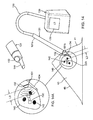
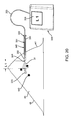
- FIG. 1 shows an exemplary embodiment of a system 10 for localization of a target tissue region within a patient's body, such as a tumor, lesion, or other tissue structure within a breast or other location within a body.
- the system 10 generally includes a marker device or localization wire 20 and a probe 30 for detecting at least a portion of the localization wire 20 using electromagnetic pulses, waves, or other signals, such as radar.
- the localization wire 20 may include an elongated member or shaft 22 including a proximal end 22a, a distal end 22b, and a target 26 on the distal end 22b.
- the system 10 may include one or more additional localization wires and/or targets (not shown) in addition to localization wire 20.
- the shaft 22 may be formed from a relatively rigid material, e.g., a solid rod or hollow tubular body, having sufficient column strength to facilitate percutaneous introduction of the localization wire 20 through tissue.
- the shaft 22 may have a length sufficient to extend from a location outside a patient's body through tissue to a target tissue region, e.g., between about half and ten centimeters (0.5-10 cm).
- the shaft 22 may be malleable or otherwise plastically deformable, e.g., such that the shaft 22 may be bent or otherwise formed into a desired shape, if desired.
- the target 26 may include one or more features on the distal end 22b of the shaft 22 to facilitate localization of the distal end 22b using the probe 30.
- the target 26 may be a bulbous structure, e.g., a sphere having a larger diameter than the distal end 22b of the shaft 22, e.g., between about half and five millimeters (0.5-5 mm).
- the target 26 may include one or more features to enhance electromagnetic signal reception and reflection.
- the target 26 may be formed from one or more materials and/or may have a surface finish that enhances detection by radar, e.g., similar to the markers described elsewhere herein.
- shapes and/or geometries may be provided, e.g., cubes, triangles, helixes, and the like, including one or more corners and/or edges that may enhance radar reflection and/or detection, similar to other embodiments herein.
- the target 26 may have a size and/or shape approximating the size and/or shape of the lesion 42, e.g., to facilitate identifying a desired margin around the lesion 42.
- the size and/or shape of the lesion 42 may be determined in advance, and a target 26 may be selected from a set of different size and/or shape targets and secured to the shaft 22 (or each target may be provided on its own shaft).
- each target may have a different shape and/or features, e.g., to facilitate distinguishing the targets from one another using the probe 30.
- the shaft 22 and target 26 may be integrally formed from the same material.
- the target 26 may be formed from different material(s) than the shaft 22, and the target 26 may be secured to the distal end 22b, e.g., by bonding with adhesive, welding, soldering, interference fit, threads or other cooperating connectors, and the like.
- the target 26 may be formed from material that enhances detection by radar relative to the shaft 22.
- each target may have a surface, shape, and/or additional material feature that may distinguish a particular target relative to one or more others.
- each target may absorb or reflect a particular electromagnetic signal that is specific to that target and can be used to uniquely identify it.
- the localization wire 20 may include one or more anchoring elements 24 on the distal end 22b, e.g., adjacent the target 26, although the target 26 itself may stabilize the localization wire 20 sufficiently that anchoring elements 24 may be unnecessary.
- the anchoring elements 24 include a plurality of barbs 24 (two shown) that extend transversely from the shaft 22, e.g., angled proximally away from the target 26.
- the barbs 24 may be configured for anchoring the localization wire 20 in position after the localization wire 20 is inserted into tissue, e.g., allowing the localization wire 20 to be advanced distally through tissue while preventing subsequent proximal withdrawal.
- the barbs 24 may be sufficiently flexible such that the barbs 24 may be compressed against or otherwise adjacent the shaft 22, e.g., to minimize a profile of the localization wire 20 to facilitate advancement, yet resiliently biased to return outwardly to a transverse orientation, as shown.
- the probe 30 may be a portable device having electromagnetic signal emitting and receiving capabilities, e.g., a micro-power impulse radar (MIR) probe.
- MIR micro-power impulse radar
- the probe 30 may be a handheld device including a first end 30a intended to be placed against or adjacent tissue, e.g., a patient's skin or underlying tissue, and a second opposite end 30b, e.g., which may be held by a user.
- the probe 30 generally includes one or more antennas, e.g., a transmit antenna 32 and a receive antenna 34, one or more processors or controllers 36, and a display 38.
- the processor 36 may include one or more controllers, circuits, signal generators, gates, and the like (not shown) needed to generate signals for transmission by the transmit antenna 32 and/or to process signals received from the receive antenna 34.
- the components of the processor 36 may include discrete components, solid state devices, programmable devices, software components, and the like, as desired.
- the probe 30 may include an impulse generator 36b, e.g., a pulse generator and/or pseudo noise generator (not shown), coupled to the transmit antenna 32 to generate transmit signals, and an impulse receiver 36c for receiving signals detected by the receive antenna 34.
- the processor 36 may include a micro controller 36a and a range gate control 36d that alternately activate the impulse generator 36b and impulse receiver 36c to transmit electromagnetic pulses, waves, or other signals via the antenna 32, and then receive any reflected electromagnetic signals via antenna 34.
- Exemplary signals that may be used include microwave, radio waves, such as micro-impulse radar signals, e.g., in the Ultra Low bandwidth region.
- each of the antennas 32, 34 may be a UWB antenna, e.g., a horn obtrusive physical profile, a dipole and patch, or a co-planar antenna, such as a diamond dipole antenna, a single ended elliptical antenna ("SEA"), a patch antenna, and the like.
- the processor 36 may activate a single antenna to operate alternately as a transmit antenna and a receive antenna (not shown) instead of providing separate antennas 32, 34.
- each antenna 32, 34 may be a TEM horn antenna, such as that disclosed in " TEM Horn Antenna for Ultra-Wide Band Microwave Breast Imaging,” published in Progress in Electromagnetics Research B, Vol. 13, 59-74 (2009 ).
- each antenna 32, 34 may be a patch antenna, such as those disclosed in U.S. Publication No. 2008/ 0071169, published March 20, 2008 , and in " Wideband Microstrip Patch Antenna Design for Breast Cancer Tumour Detection,” by Nilavalan, et al., published in Microwaves, Antennas, & Propagation, IET, Volume 1, Issue 2 (April 2007), pp. 277-281 .
- the patch antenna may be coupled to an enclosure (not shown), e.g., filled with dielectric material, to facilitate use with micro-impulse radar.
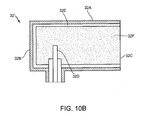
- each antenna may be a waveguide horn, e.g., as shown in FIG. 10B .
- antenna 32' includes a casing 32A that is closed on a first end 32B, and open on a second end 32C, and within which a waveguide 32D is mounted.
- the walls of the casing 32A may be lined with an absorber material 32E, e.g., a broadband silicone absorber material, such as Eccosorb-FGM40, sold by Emerson & Cuming Microwave Products N.V. of Westerlo, Belgium.
- the volume within the casing 32A may be filled with a dielectric 32F, e.g., having a relative permittivity of 10.
- the antenna 32' may be a square waveguide horn configured to operate at ultrawide band frequencies 9"UWB") between about three and ten Gigahertz (3-10 Ghz), e.g., having a width of about fifteen by fifteen millimeters (15x15 mm), and a length between the first and second ends 32B-32C of about thirty millimeters (30 mm).
- the open end 32B may be oriented outwardly from a probe within which the antenna 32' is mounted, e.g., such that the open end 32B may contact or otherwise be coupled with tissue through which the antenna 32' is intended to transmit and/or receive signals, as described elsewhere herein.
- the signals from the impulse receiver 36c may be filtered or otherwise processed, e.g., by a return signal de-clutter and shaper circuit 36e, before being communicated to the micro-controller 36a for further processing, display, storage, transmission, and the like.
- the circuit 36e may receive signals from the antenna 34, e.g., return echo noise and clutter, may de-clutter the signals, e.g., using LPF, and/or may include digital adaptive filtering and/or pulse shapers, as desired.
- the micro-controller 36a may then interpret the received and/or processed signals to identify a spatial relationship, e.g., distance, angle, orientation, and the like, of the target 26 or other structures relative to the probe 30, as described further below. Exemplary embodiments of processors and/or other components that may be included in the probe 30 are disclosed in U.S. Patent Nos. 5,573,012 and 5,766,208, issued to McEwan .
- the probe 30 may be configured to operate as a magneto-radar system, such as that disclosed in U.S. Patent No. 6,914,552, issued to McEwan .
- the probe 30 may include a magnetic field excitation source, e.g., an electromagnet (not shown), coupled to a generator and/or current coil driver (not shown), which may be provided within or external to the probe 30.
- the probe may induce a magnetic field to a marker or other target, generating a pole to pole vibration at a specific frequency that the radar unit may identify and/or recognize to provide a distance measurement or location coordinates.
- a probe may be useful when the target is implanted in tissue, bone, or bodily fluid with a relatively high impedance or dielectric constant that may attenuate the radar pulse from reaching the target or the reflected signal from reaching the radar antenna.
- the probe's display 38 may be coupled to the micro-controller 36a for displaying information to a user of the probe 30, e.g., spatial or image data obtained via the antenna(s) 32, 34.
- the display 38 may simply be a readout providing distance, angle, orientation, and/or other data based on predetermined criteria, e.g., based on the relative location of the target 26 to the probe 30, as described further below.
- FIG. 10A shows an exemplary embodiment of an output for display 38 that may be provided, which may include an array of arrows or other indicators 38a and a distance readout 38b.
- the micro-controller 36a may analyze the received signals to determine in which direction relative to the probe 30 a marker (not shown) may be located and activate the appropriate arrow 38a, and display a distance (e.g., "3 cm” shown) to the marker.
- a distance e.g., "3 cm” shown
- the user may be able to identify in what direction and how far in that direction the marker is located, thereby providing the user guidance towards the marker and the target tissue region within which the marker is implanted.
- the display 38 may provide other information, e.g., real-time images of the region towards which the probe 30 is oriented, i.e., beyond the first end 30a, operational parameters of the probe 30, and the like.
- the probe 30 may include one or more other output devices in addition to or instead of the display 38.
- the probe 30 may include one or more speakers (not shown) that may provide audio output, one or more LEDs or other light sources that provide visual output, and the like e.g., to provide information such as spatial information, operation parameters, and the like.
- a speaker or LED may be activated when the probe 30 reaches a predetermined threshold distance from the marker, e.g., a desired margin, or may be activated when successively closer distances are achieved.
- the probe 30 may include other features or components, such as one or more user interfaces, memory, transmitters, receivers, connectors, cables, power sources, and the like (not shown).
- the probe 30 may include one or more batteries or other internal power sources for operating the components of the probe 30.
- the probe 30 may include a cable (not shown) that may be coupled to an external power source, e.g., standard AC power, for operating the components of the probe 30.
- the user controls 37 may include one or more input devices, such as a keypad, touch screen, individual buttons, and the like (not shown).
- the user controls 37 may allow the user to perform simple operations, e.g., turn the probe 30 on and off, reset the probe 30, and the like, or may allow more complicated control of the probe 30.
- the user controls 37 may allow the sensitivity or other parameters of the probe 30 to be adjusted, may allow data to be captured, stored, transmitted remotely, and the like.
- the probe 30 may include internal memory 36f that may record or otherwise store data obtained via the antenna(s) 32, 34 and/or micro-controller 36a.
- the micro-controller 36a may automatically record data during operation, or may be instructed to selectively save data to the memory 36f.
- the micro-controller 36a may transfer data to one or more external devices, e.g., for storage, display, and the like.
- the probe 30 may include one or more cables (not shown) to allow such data transfer and/or the probe 30 may include a transmitter and/or receiver (not shown) for wirelessly transferring data and/or receiving commands, e.g., via radio frequency, infrared, or other signals.
- the internal components ofthe probe 30 may be provided in a housing or casing 39 such that the probe 30 is self-contained.
- the casing 39 may be relatively small and portable, e.g., such that the entire probe 30 may be held in a user's hand.
- the first end 30a of the casing 39 may be formed from like or different materials than other portions of the casing 39.
- the first end 30a may be formed from materials that easily accommodate passage of electromagnetic signals therethrough, e.g., from the transmit antenna 32 and/or to the receive antenna 34, without substantial interference.
- the materials may be selected to reduce interference, match impedance, or otherwise facilitate transmitting and receiving signals via the probe 30 into and out of a patient's body.
- the probe 30 may include a handle, finger grips, and/or other features (not shown) to facilitate holding or otherwise manipulating the probe 30.
- a probe instrument 130 may be provided that includes a separate controller 139 including one or more of the components within a casing remote from a handheld probe 131.
- the handheld probe 131 may include an elongate housing 131a including a tip 131b with one or more antennas 132.
- the controller 139 may include one or more processors for controlling the antenna(s) 132, a display 138, and the like, similar to the previous embodiments.
- the handheld probe 131 may be coupled to the processor(s) in the controller 139 by one or more cables 133.
- an impulse generator, impulse receiver, and/or gate control may be provided within the casing of the controller 139 or, optionally, within the housing 131a, if desired.
- the cable 133 may be removably connectable to a connector (not shown) on the controller 139 for electrically coupling the antenna 132 of the handheld probe 131 to the electronics within the controller 139.
- the handheld probe 131 may be a disposable, single-use device while the controller 139 may be used during multiple procedures by connecting a new handheld probe 131 to the controller 139, which may remain out of the surgical field yet remain accessible and/or visible, as desired, as explained further below.
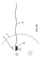
- the localization system 10 of FIG. 1 may be used during a medical procedure, for example, in a breast biopsy or lumpectomy procedure, e.g., to facilitate localization of a lesion or other target tissue region 42 and/or to facilitate dissection and/or removal of a specimen from a breast 41 or other body structure.
- a medical procedure for example, in a breast biopsy or lumpectomy procedure, e.g., to facilitate localization of a lesion or other target tissue region 42 and/or to facilitate dissection and/or removal of a specimen from a breast 41 or other body structure.
- the system 10 is described as being particularly useful in localization of breast lesions, the system 10 can also be used in localization of other objects in other areas of the body, e.g., as described elsewhere herein.
- a target tissue region e.g., a tumor or other lesion
- a lesion 42 within a breast 41 may be identified, e.g., using mammography and/or other imaging, and a decision may be made to remove the lesion 42.
- the dashed line 44 surrounding the tumor 42 defines a "clear" margin, e.g., indicating the size and shape of a desired tissue specimen 46 that is to be removed during the procedure.
- the margin 44 may be selected to ensure that the remaining tissue after removing the specimen 46 is substantially clear of cancerous or other undesired cells.
- the distance between the outer boundaries of the lesion 42 and the outer edges or margin 44 of the tissue specimen 46 may be between about one and ten millimeters (1-10 mm), e.g., at least about two millimeters (2 mm) or at least about one centimeter (1 cm).
- the localization wire 20 may be introduced percutaneously through tissue 40, e.g., from the patient's skin 48 through intervening tissue until the target 26 is positioned within the lesion 42.
- the localization wire 20 may be introduced through a delivery sheath (not shown), which may be placed previously using a needle and/or dilator (also not shown), similar to the cannula 340 described with reference to FIGS. 20-22 elsewhere herein.
- a cannula or delivery sheath having a sharpened tip may be penetrated through the skin 48 and intervening tissue 40 into the lesion 42, e.g., using ultrasound or x-ray imaging for guidance, and then the localization wire 20 may be advanced through the cannula.
- a needle having a sharpened tip may be advanced through tissue and then a delivery sheath may be advanced over the needle (not shown), e.g., along with a dilator between the needle and delivery sheath. Once the delivery sheath is positioned such that it extends from the skin 48 to the lesion 42, the needle and any dilator may be removed.
- the distal end 22b of the localization wire 22 may then be advanced through the delivery sheath until the target 26 is positioned within the lesion 42, whereupon the delivery sheath may be removed.
- the localization wire 22 may include one or more markers (not shown) on the distal end, e.g., radiopaque or echogenic markers, on or adjacent the target 26, to facilitate imaging the target 26 and/or distal end 22b of the localization wire 22. External imaging may then be used during and/or after introduction of the localization wire 20 to ensure that the target 26 is properly positioned within the lesion 42.
- the localization wire 20 includes anchoring element(s), such as barbs 24, the barbs 24 may be compressed inwardly when the localization wire 20 is advanced through the delivery sheath. Once the target 26 is positioned within the lesion 42, the delivery sheath may be withdrawn, whereupon the barbs 24 may resiliently expand outwardly into the adjacent tissue. Thus, the barbs 24 on the distal end 22b of the shaft 22 may anchor the localization wire 20 relative to the lesion 42, e.g., such the target 26 may be substantially secured in a fixed position within the lesion 42.
- anchoring element(s) such as barbs 24
- a bandage, tape, and the like may be used to secure the proximal end 22a of the localization wire 22a to the patient's skin 48, e.g., to prevent migration of the localization wire 22.
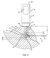
- the first end 30a of the probe 30 may be placed adjacent or in contact with the patient's skin 48, e.g., generally above the lesion 42, and/or otherwise aimed generally towards the target 26, and activated, as shown in FIG. 3 .
- the transmit antenna 32 (not shown, see FIG. 10 ) of the probe 30 may emit electromagnetic signals 31 that travel through the tissue 40 and are reflected off of the target 26.
- the signals 33 may be reflected back to the receive antenna 34 (not shown, see FIG. 10 ) in the probe 30.
- the probe 30 may then determine a spatial relationship between the target 26 and the first end 30a of the probe 30, e.g., a distance 52 between the target 26 and the probe 30 (and the patient's skin 48 if contacted by the first end 30a of the probe 30), e.g., based on the distance traveled by the signals 31, passage of time between transmission of signals 31 and reception of reflected signals 33, and the like.
- the probe 30 may also determine a relative angle between the target 26 and the first end 30a, e.g., to facilitate determining a proper direction of dissection.
- the micro-controller 36a (not shown, see FIG. 10 ) of the probe 30 may filter or otherwise analyze received signals to identify the target 26, e.g., based on recognition of the size, shape, or other aspects of the target 26.
- the micro-controller 36a may automatically be able to identify the target 26 and distinguish it from other structures that may be present in the patient's body.
- the micro-controller 36a may simply identify any objects reflecting signals back to the probe 30, which presumably would identify the target 26.
- the micro-controller 36a may calculate the distance 52 and/or an angle relative to an axis extending orthogonally from the first end 30a of the probe 30, and display this spatial information on the display 38.
- This information may facilitate localizing the target 26, and consequently the lesion 42, which may provide guidance to a surgeon dissecting tissue overlying the lesion 42, e.g., by providing a direction and depth of dissection to access the target tissue region including the lesion 42.
- the display 38 may provide a distance 54 between the target 26 and the outer margin 44 of the target tissue specimen 46, which may facilitate defining the targeted size and shape of the tissue specimen 46 to be removed.
- the probe 30 may automatically subtract a predetermined distance between the desired margin 44 and the target 42, e.g., based on preset parameters programmed into the processor 36 of the probe 30 or based on dimensions provided to the micro-controller 36a by the user immediately before the procedure, e.g., via user controls 37 (not shown, see FIG. 10 ).
- the probe 30 may be positioned at several locations against or otherwise adjacent the skin 48 and spatial information obtained, if desired. Such information may facilitate the surgeon determining an optimal approach path for dissection, e.g., the shortest path to the lesion 42, or otherwise help orient the surgeon relative to the lesion 42 in three dimensions.
- the tissue 40 may be dissected to reach the predetermined outer edge 44 of the tissue specimen 46, as shown in FIG. 4 .
- an incision may be made in the patient's skin 48 at the location where the probe 30 was placed and the intervening tissue dissected using known methods until the depth corresponding to the margin 44 is achieved.
- the probe 30 may be placed against or adjacent the exposed tissue and spatial information obtained to confirm the approach and/or depth of dissection.
- the tissue specimen 46 may be excised or otherwise removed using conventional lumpectomy procedures with the target 26 remaining within the removed specimen 46. If desired, the target 26 may be separated from the shaft 22 to facilitate removal of the specimen 46, e.g., by cutting the distal end 22b of the shaft 22, by disconnecting any connectors (not shown) between the shaft 22 and target 26, and the like.
- the probe 30 may be used to analyze the excised tissue specimen 46, e.g., to confirm that the desired margin 44 has been achieved around the target 26, and consequently around the lesion 42.
- transmit signals 31 are transmitted by the probe 30 and signals 33 are reflected off the target 26 and received by the probe 30, whereupon the probe 30 may determine and display the distance 54 and/or any other spatial information. In this manner, it can be verified that the predetermined tissue margin has been achieved.
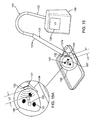
- FIGS. 6-9 another exemplary embodiment of a system 110 for localizing a lesion or other tissue structure, e.g., a plurality of non-palpable lesions 142, is shown that includes a probe 30 and a plurality of implantable markers or targets 120.
- the probe 30 may be a portable device capable of transmitting electromagnetic signals and receiving reflected signals, similar to the embodiments described elsewhere herein.
- the markers 120 may include a plurality of implantable elements sized for introduction through tissue into a region surrounding the lesion 142.
- the markers 120 may be formed as a plurality of strips, cylinders, helixes, spheres, and the like, e.g., having features to enhance reflection of electromagnetic signals transmitted by the probe 30, similar to the target 26 described above with reference to FIG. 1 and/or the markers described further elsewhere herein, e.g., with reference to FIGS. 23A-28C , 34A, 34B, 41A, and 41B .
- the markers 120 may be elongate strips, e.g., rectangular or other shaped markers having a length between about half to four millimeters (0.5-4.0 mm), a width between about half and two millimeters (0.5-2.0 mm), and a thickness between about half and three millimeters (0.5-3.0 mm).
- the markers 120 may be formed from metal or other material that may enhance detection by the probe 30, e.g., having a desired dielectric constant.
- the markers 120 may be formed from bioabsorbable material, e.g., such that the markers 120 may be implanted within tissue and then dissolved or otherwise absorbed by the tissue over time, e.g., over several days, weeks, or months.
- the markers 120 may be formed from radiopaque material, radioactive material, and/or echogenic material, which may facilitate imaging or otherwise monitoring the markers 120, e.g., during introduction, after placement during a procedure, or afterwards if the markers 120 remain within the patient's body after the procedure.
- each marker 120 may have a surface, shape, and/or additional material feature that may distinguish one or more of the markers from others, as described elsewhere herein.
- each marker 120 may modulate an incident signal from the probe 30 in a predetermined manner and/or absorb or reflect a particular electromagnetic signal that is specific to that marker 120 and may be used to uniquely identify it.
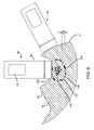
- the system 110 may also include one or more delivery devices 160 for introducing the markers 120 into a patient's body.
- a delivery device 160 may be provided that includes a shaft 162 including a proximal end 162a and a distal end 162b sized for introduction through tissue into a target tissue region (not shown) and carrying one or more markers 120.
- the delivery device 160 may include a lumen 164 extending at least partially between the proximal and distal ends 162a, 162b of the shaft 162, and a pusher member 166 slidable within the shaft 162 for selectively delivering one or more markers 120 successively or otherwise independently from the lumen 164.
- the distal end 162b of the shaft 162 may be beveled and/or otherwise sharpened such that the shaft 162 may be introduced directly through tissue.
- the delivery device 160 may be introduced through a cannula, sheath, or other tubular member (not shown) previously placed through tissue, e.g., as described elsewhere herein.
- the distal end 162b may include a band or other feature, e.g., formed from radiopaque, echogenic, or other material, which may facilitate monitoring the distal end 162b during introduction, e.g., using fluoroscopy, ultrasound, electromagnetic signals, and the like.
- the pusher member 166 includes a piston or other element (not shown) disposed within the lumen 164 adjacent the marker(s) 120 and a plunger or other actuator 168 coupled to the piston for advancing the piston to push the marker(s) 120 from the lumen 164.
- the plunger 168 may be manually advanced to deliver one or more markers 120 successively from the lumen 164.
- a trigger device or other automated actuator may be provided on the proximal end 162b of the shaft 162, which may advance the piston sufficiently with each activation, e.g., to delivery an individual marker 120 from the distal end 162b.
- an exemplary method is shown for using the markers 120 and probe 30 to localize a lesion or other target tissue region 142 within a breast 41 or other tissue structure.
- the markers 120 may be implanted within the tissue 40 to delineate a desired margin or volume 144 of a tissue specimen 146 to be excised.
- the shaft 162 of the delivery device 160 may be inserted percutaneously through the patient's skin 48, through any intervening tissue 40, and the distal end 162b positioned within or around the lesion 142, e.g., using external imaging to guide the distal end 162b to a desired location.
- the plunger 168 may be advanced (or the shaft 162 withdrawn relative to the plunger 168) to deliver a marker 120 into the tissue.
- the delivery device 160 may be advanced further to another location and/or removed entirely from the breast 41 and reintroduced through another location of the skin 48 into the target tissue region, e.g., to deliver one or more additional markers 120.
- the delivery device 160 may carry only a single marker 120, and multiple delivery devices (not shown) may be provided for delivering each of the markers 120.
- a stereotactic device (not shown) may be used, e.g., to introduce one or multiple delivery devices into the patient's body in a desired three-dimensional array or other arrangement for localizing the lesion 142.
- the markers 120 may be replaced with multiple localization wires, similar to wire 10, one or more catheters (not shown) which may be delivered sequentially, simultaneously, and the like.
- the catheter(s), wire(s), or other devices may be expandable, e.g., at a distal region (not shown) to facilitate dilating and/or identifying a specimen volume or region.
- the markers 120 surround a group of non-palpable lesions 142, e.g., before or during a procedure to remove a specimen volume surrounding the lesions 142.
- the distance 156 between the outer edge 144 of the tissue specimen 146 and the lesions 142 may be selected to ensure that the volume of tissue removed is sufficient to ensure clear margins, similar to the methods described above.
- the probe 30 may be placed against or otherwise adjacent the patient's skin 48 (e.g., it may be unnecessary to contact the patient's skin 48 with the probe 30 to transmit and receive signals into and from the tissue 40), and the probe 30 may be used to determine the distance 152 (and/or other spatial information) between the probe 30 and the markers 120, similar to the previous embodiments.
- the signals 31 emitted by the probe 30 may be received at the markers 120 and reflected back to a receiver in the probe 30 as signals 33, and the probe 30 may use the signals to determine the distance 152 between the patient's skin 48 and the markers 120.
- the tissue 40 surrounding the lesions 142 may then be dissected until one of the markers 120 is encountered, as shown in FIG. 8 . At this point, another measurement may be taken with the probe 30 to ensure proper dissection depth. The probe 30 may then be repositioned, as shown in phantom in FIG. 8 , to locate another one of the markers 120 around the periphery 144 of the tissue specimen 146. The resulting distance measurements may be used to determine a desired margin volume for excision around the lesions 142. This process may be repeated as often as desired to facilitate measuring the desired margin based on the distance to the markers 120 during excision of the tissue specimen 146 around the lesions 142.
- the tissue specimen 146 may include the markers 120 therein such that all of the markers 120 are removed with the tissue specimen 146.
- the desired margin may be defined within the markers 120 such that the markers 120 remain within the breast after the tissue specimen 120 is removed.
- the markers 120 may be bioabsorbable or may be inert and remain indefinitely within the patient's breast 41.
- FIGS. 11-15 another exemplary system and method are shown for localizing one or more lesions 142 within a breast 41 and/or removing a tissue specimen 146 (shown in FIGS. 14A-15A ) including the lesion(s) 142.
- the system includes one or more markers 220 and a probe instrument 130, which may facilitate localizing the lesion(s) 142 and/or ensuring desired margins are achieved for the tissue specimen 146 removed from the breast 41.
- the probe instrument 130 includes a handheld probe 131 coupled to a processor 139 including one or more processors for controlling operation of the probe 131, as described above.
- the handheld probe 131 includes an elongate housing 131a including one or more antennas 132 on or within a tip 131b on one end of the probe 131 that may be placed against the skin 48 or other tissue and/or otherwise oriented generally towards the marker 220 and/or lesion(s) 142.
- the processor 139 may include one or more processors for controlling the antenna(s) 132, a display 138, and the like, similar to the previous embodiments.
- the handheld probe 131 may be coupled to the processor 139 by one or more cables 133.
- an impulse generator, impulse receiver, and/or gate control may be provided within the processor 139, which may be controlled to emit and receive signals via the antenna(s) 132.
- the handheld probe 131 may include a dissecting feature 133, e.g., extending from the tip 131b ofthe housing 131a.
- the dissecting feature 133 may be a relatively flat blunt dissector fixed to the tip 131b of the probe 131, e.g., having a length of about ten to fifty millimeters (10-50 mm) and/or a width of about one to ten millimeters (1-10 mm).
- the dissecting feature 133 may be retractable, e.g., such that the dissecting feature 133 may be initially retracted within the housing 131a, but may be selectively deployed when desired to dissect layers of tissue to access tissue adjacent the marker 220.
- the dissecting feature 133 may include a sharpened blade or edge, which may facilitate cutting through the patient's skin 48 and/or underlying layers of tissue 40.
- one or more markers 220 may be implanted within the target tissue region, e.g., using the markers and/or methods described elsewhere herein.
- the probe 131 may be coupled to the processor 139, e.g., by cable 133, and the tip 131b placed against the skin 48.
- the probe 131 may be activated, e.g., to obtain an initial distance measurement from the tip 131b of the probe 131 to the marker 220 using the antenna(s) 132, thereby providing an approximate distance to the lesion(s) 142.
- the distance measurement may be displayed on the display 138 of the processor 139, e.g., as shown in FIG. 12 , and/or otherwise provided to the user.
- a speaker may provide the distance measurement, e.g., using a synthesized voice, one or more tones identifying corresponding distances, and the like, to identify the distance.
- the processor 139 may analyze the received signals to determine the actual distance from the tip 131b of the probe 131 to the marker 220, and may provide the actual measurement via the speaker.
- the speaker may provide a tone corresponding to a predetermined threshold, e.g., a first tone for a first threshold distance, a second tone or multiple tones for a second, closer distance, and the like, thereby indicating to the user that they are getting closer to the marker 220.
- a measurement L1 is obtained, while with the probe 131' placed on a second opposite side of the breast 41, a measurement L2 is obtained, which is greater than L1.
- the physician may decide to initiate dissection on the first side since it provides a shorter path requiring less tissue dissection than a path initiated from the second side, as shown in FIG. 12 .
- the probe 131 may be used to identify a desired margin L3 around the marker 220 and consequently around the lesion(s) 142. For example, if a desired margin L3 of one centimeter (1 cm) is desired, the probe 131 may be display or otherwise provide the actual distance L1 from the probe 131 to the marker, as shown on the display 138, thereby indicating that the probe 131 remains outside the margin L3. Alternatively, if the processor 139 knows the desired margin L3, the display 138 may provide the difference between the actual distance L1 and the desired margin L3 (i.e., L1-L3), thereby informing the physician of the depth of dissection necessary to attain the desired margin.
- L1-L3 the difference between the actual distance L1 and the desired margin L3
- the blunt dissector 144 may be deployed from the tip 131b of the probe 131 (if not permanently deployed) and advanced through the tissue 40 towards the marker 220, e.g., until the desired margin L3 is attained.
- the probe 131 may then be manipulated to dissect tissue around the marker 220 using the blunt dissector 144 and/or using one or more additional dissectors, scalpels, or other tools (not shown).
- a tissue specimen 146 has been removed from the breast 41 that includes the marker 220 and the lesion(s) 142 therein.
- the probe 131 may then be used to confirm that the desired margin L3 was achieved around the marker 220, thereby providing confirmation that sufficient tissue has been removed from the breast 41, similar to the previous embodiments.
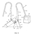
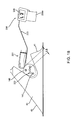
- FIGS. 16A and 16B still another embodiment of a system is shown that includes one or more markers 220, a probe 231 including a finger cot 231a carrying one or more antennas 232, and a processor 239 coupled to the antenna(s) 232, e.g., by cable 233.
- the finger cot 231a may be a flexible sleeve, e.g., including an open end 231b into which a finger 90 may be inserted, a closed end 231c, and having sufficient length to be securely received over the finger 90.
- the finger cot 231a may be formed from elastic material, such as a relatively thin layer of latex, natural or synthetic rubber, and the like, e.g., similar to surgical or examination gloves, having sufficient flexibility to expand to accommodate receiving the finger 90 while compressing inwardly to prevent the finger cot from 231a sliding off the finger 90 during use.
- elastic material such as a relatively thin layer of latex, natural or synthetic rubber, and the like, e.g., similar to surgical or examination gloves, having sufficient flexibility to expand to accommodate receiving the finger 90 while compressing inwardly to prevent the finger cot from 231a sliding off the finger 90 during use.
- the antenna(s) 232 may be provided adjacent the closed end 231c, as shown.
- the antenna(s) 232 may include a transmit antenna and a receive antenna (not shown), similar to the previous embodiments, provided within a casing.
- the casing may be attached to the finger cot 231a, e.g., adjacent the closed end 231c, for example, by bonding with adhesive, fusing, one or more overlying bands (not shown), and the like.
- the processor 239 may include one or more components for operating the antenna(s) 232 and/or processing signals received from the antenna(s) 232, e.g., coupled to the antenna(s) 232 by cable 233 and including display 238, similar to the previous embodiments.
- the processor 239 includes one or more clips 239a, straps, belts, clamps, or other features (not shown) that allow the processor 239 to be removably secured to the arm of a user whose finger is inserted into the finger cot 231a.
- the clips 239a may be curved to extend partially around a user's forearm, and the clips 239a may be sufficiently flexible to open them to receive an arm therein and then resiliently close to engage at least partially around the arm.
- the processor 239 may be provided in a casing (not shown) that may be placed remotely from the patient and/or user, e.g., similar to the processor 139 described above.
- a physician or other user may insert one of their fingers 90, e.g., their index finger or thumb, into the finger cot 231a, and the processor 239 may be activated to send and receive signals via the antenna(s) 232, similar to the previous embodiments.
- the finger 90 inserted into the finger cot 231a may be placed against the patient's skin 48 and distance measurements obtained to identify the distance to the marker 220.
- the user may insert the finger 90 into the path created, as shown in FIG. 18 , thereby providing direct feedback to the user of the location of the marker 220, and consequently, the lesion(s) 142, relative to the finger 90.
- this embodiment of the probe 231 may provide tactile feedback as well as distance measurements, which may facilitate dissection and/or removal of a tissue specimen 146 including the marker 220 and lesion(s) 142 therein. For example, as shown in FIG.
- an initial distance measurement L1 may be obtained informing the user of the depth of dissection needed, while, as shown in FIG. 18 , a distance measurement L2 may be obtained (corresponding to the desired margin), thereby informing the user that sufficient dissection has been achieved and the tissue specimen 146 may be isolated and removed, similar to the previous embodiments.
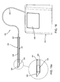
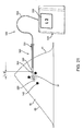
- the system includes a probe instrument 330, including a handheld probe 331 coupled to a processor 339, similar to the previous embodiments.
- the probe 331 includes one or more antennas 332, and the processor 238 includes a display 338.
- the system includes a cannula or other tubular member 340 that includes a proximal end 342, distal end 344, and a lumen 346 extending therebetween.
- the cannula 340 may be a substantially rigid tubular body having a size such that the probe 331 may be received within the lumen 346, as shown in FIG. 19 .
- the distal end 344 may be beveled, sharpened, and/or otherwise formed to facilitate advancement directly through tissue.
- the distal end 344 may be tapered and/or rounded (not shown), e.g., such that the cannula 340 may be advanced over a needle (not shown) either before or after the needle has been introduced into the tissue 40, similar to the previous embodiments.
- the probe 330 may be inserted into the lumen 346 of the cannula 340, e.g., such that the antenna(s) 332 are disposed immediately adjacent the distal end 344 of the cannula 340.
- the cannula 340 and/or probe 331 may include one or more connectors (not shown) for releasably securing the probe 331 relative to the cannula 340, e.g., to maintain the antenna(s) 332 adjacent the distal end 344, while allowing the probe 331 to be removed when desired.
- the cannula 340 may include one or more seals (not shown), e.g., within the proximal end 342 and/or distal end 344, to provide a substantially fluid-tight seal when the probe 331 is disposed within the lumen 346 and/or when the probe 331 is removed.
- a hemostatic seal (not shown) may be provided in the proximal end 342 that may provide a seal to prevent fluid flow through the lumen 346, yet accommodate receiving the probe 331 or other instruments (not shown) therethrough.
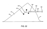
- the distal end 344 of the cannula 340 may be inserted through the patient's skin 48 and tissue 40 towards the marker 220.
- the probe 331 may transmit signals 31 and the display 338 of the processor 339 may provide a distance measurement L1 or other indication of the relative location of the marker 220 to the antenna(s) 332 based on the reflected signals received by the antenna(s) 332, and consequently, relative to the distal end 344 of the cannula 340.
- the depth of penetration and/or direction of advancement of the cannula 340 may be adjusted based upon the information provided by the probe 331 and processor 339.
- the cannula 340 may be advanced until a desired distance L2 is achieved, thereby placing the distal end 344 a desired distance away from the marker 220, e.g., within a target tissue region adjacent the lesion(s) 142.
- the probe 331 may be removed, leaving the cannula 340 in place, as shown.
- the cannula 340 may thereby provide a passage for accessing the target tissue region, e.g., to perform one or more diagnostic and/or therapeutic procedure.
- a needle or other tool (not shown) may be advanced through the lumen 346 of the cannula to perform a biopsy and/or to deliver fluids or other diagnostic or therapeutic material into the target tissue region.
- one or more instruments may be introduced through the cannula 340 for removing a tissue specimen, e.g., including the lesion(s) 142, for delivering radiation therapy, and/or other procedures.
- a tissue specimen e.g., including the lesion(s) 142
- the cannula 340 may simply be removed.
- the probe 331 may be reintroduced into the lumen 346 and the cannula 340 relocated within the tissue with the probe 331 providing additional guidance.
- markers 220 are shown, which may be implanted or otherwise placed within the tissue 40, e.g., within or otherwise adjacent the lesion(s) 142, using methods similar to those described above.
- the markers 220 are generally elongate bodies including relatively narrow middle stem portions between bulbous ends.
- the markers 220 may be formed from desired materials and/or may include surface features similar to other markers herein, which may facilitate localization of the markers 220 and/or distinguishing markers from one another.
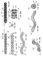
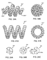
- a first exemplary marker 320 is shown that includes a core wire 322 carrying a plurality of beads or segments 324.
- the core wire 322 may be an elongate member, e.g., a solid or hollow structure having a diameter or other maximum cross-section between about half and two millimeters (0.5-2 mm) and a length between about one and ten millimeters (1.0-10 mm).
- the core wire 322 may be formed from elastic or superelastic material and/or from shape memory material, e.g., stainless steel, Nitinol, and the like, such that the core wire 322 is biased to a predetermined shape when deployed within tissue, as explained further below.
- the core wire 322 may be substantially rigid such that the marker 320 remains in a fixed shape, e.g., linear or curved, as described further below.
- the beads 324 may include a plurality of individual annular bodies, e.g., each defining a portion of a generally cylindrical or spherical shape.
- the beads 324 may be formed from desired materials similar to the previous embodiments, e.g., metals, such as stainless steel, Nitinol, titanium, and the like, plastic materials, or composite materials.
- the beads 324 may be formed by injection molding, casting, machining, cutting, grinding base material, and the like.
- a desired finish may be applied to the beads 324, e.g., by sand blasting, etching, vapor deposition, and the like.
- each bead 324 may include a passage 326 therethrough for receiving the core wire 322 (not shown, see, e.g., FIGS. 23A-23C ) therethrough.
- the beads 324 may include shapes and/or surface features to allow the beads 324 to be nested at least partially adjacent one another when secured onto the core wire 322, yet allow the marker 320 to change shape, e.g., as the core wire 322 changes shape.
- each bead 324 may include a first convex or bulbous end 324a and a second concave end 324b including flat surfaces 324d. As shown in FIG.
- adjacent beads 324' may define recesses 324c' between the flat surfaces 324d' on the concave end 324b' of a first bead 324 and a surface 324e' on the bulbous end 324a' of the adjacent bead 324.
- the surfaces 324d' and 324e' may define abrupt corners therebetween, which may enhance detection using radar, e.g., defining angles of about ninety degrees (90°).
- the beads 324' may include a desired surface finish 324f' intended to customize reflected signals generated when electromagnetic signals strike the surfaces of the beads 324.
- the surface finish 324f may include a plurality of pores or dimples formed in the beads 324' and having a desired diameter and/or depth.
- the probes and processors described elsewhere herein may analyze such reflected signals to uniquely identify a particular marker, e.g., when multiple markers are implanted or otherwise placed within a patient's body.
- a plurality of beads 324 may be placed over and secured to the core wire 322 to provide a finished marker 320.
- the core wire 322 may be inserted successively through the passages 326 in the beads 324 until beads 324 extend substantially between the ends of the core wire 322.
- the beads 324 may be secured to the core wire 322, e.g., by crimping individual beads 324 onto the core wire 322, crimping or otherwise expanding the ends of the core wire 322 after sliding on sufficient beads 324, bonding with adhesive, fusing, and the like.
- the beads 324 may be substantially permanently attached to the core wire 322 such that the beads 324 cannot move or the beads 324 may be free floating on the core wire 322, e.g., which may facilitate bending or otherwise shaping the core wire 322, and consequently the marker 320.
- the marker 320 may be formed from a single piece of material, e.g., such that the shapes and surfaces defined by the beads 324 shown in FIGS. 23A are formed in the workpiece.
- the core wire 322 may be eliminated, or a passage may be formed through the workpiece for receiving the core wire 322.
- the marker 320 may define a substantially fixed shape, e.g., a linear shape as shown in FIGS. 23A and 23B , or a curvilinear shape, as shown in FIGS. 23D and 26A-26C .
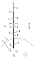
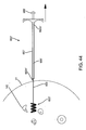
- the core wire 322 of the marker 320 may be sufficiently flexible such that the marker 320 may be straightened, e.g., to facilitate loading the marker 320 into a delivery device and/or otherwise delivering the marker 320, yet the marker 320 may be biased to a curvilinear or other nonlinear shape.
- the marker 320 may be biased to assume a wave configuration, e.g., a serpentine or other curved shape lying within a plane.
- the core wire 322 may be formed from elastic or superelastic material that is shape set such that the core wire 322 is biased to the wave configuration, yet may be resiliently straightened to a linear configuration.
- the beads 324 may be spaced apart or otherwise nested such that the beads 324 do not interfere substantially with the transformation of the core wire 322 between the linear and wave configurations, e.g., to facilitate loading the marker 320 into a delivery device and/or introducing the marker 320 into a body.
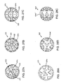
- a marker 320"' may be provided that is biased to assume a tapered helical shape, e.g., including a relatively wide intermediate region 320a"' between tapered end regions 320b.
- FIGS. 41A and 41B Another alternative embodiment of a marker 320"” is shown in FIGS. 41A and 41B that is biased to assume a substantially uniform diameter helical shape.
- markers 320,"' 320" may provide a relatively constant and/or consistent Radar Cross Section ("RCS") regardless of the reflective angle and/or position of the markers 320,"' 320”” relative to the antenna(s) of the probe (not shown).
- the markers 320,"' 320"" may provide a RCS substantially similar to when viewed laterally relative to the helical axis, e.g., as viewed in FIGS. 34A and 41A .
- any of the markers described herein may be provided as a passive marker, an active marker, an active reflector, or an active transponder.
- the marker 320 may simply be a "passive reflector," i.e., the marker 320 may simply reflect incident waves or signals striking the marker 320. The incident signals may be reflected off of the various surfaces and/or edges of the marker 320, e.g., thereby providing reflected waves or signals that may be detected by a probe, as described further elsewhere herein.
- One disadvantage of a passive marker is that the Radar Cross Section (RCS) may change based on the aspect angle of the antenna of the probe and the marker 320, which may cause changes in the strength of the returned signal reflected from the marker 320.
- RCS Radar Cross Section
- the marker 320 may include one or more features to provide an "active reflector," i.e., a marker 320 that includes one or more electronic circuits that modulate signals striking the marker 320 in a predetermined manner without adding external energy or power to the reflected signals.
- a marker may include an active reflector radio element that includes a modulated dipole or other type of active reflector antenna, e.g., including one or more very low power diodes and/or FET transistors that require very little current to operate.
- the active reflector may provide a substantially unique radar signal signature in an embedded tissue environment that may be detected and identified by a probe.
- the active reflector may provide a relatively larger signal return to the probe, e.g., thereby maintaining a target RCS regardless of antenna aspect.
- the marker 320 may include one or more circuits or other elements (not shown) coupled to or embedded in the marker 320 that may modulate incident waves or signals from the probe.
- a nanoscale semiconductor chip may be carried by the marker 320 that does not include its own energy source and therefore merely processes and modulates the signals when they are received and reflected off the marker 320.
- active reflectors that may be provided on a marker are disclosed in U.S. Patent No. 6,492,933 .
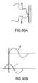
- FIGS. 50A and 50B show an example of modulation of a reflected signal B relative to an incident signal A that may be achieved using an active reflector.
- Incident signal A may represent waves or signals transmitted by a probe (not shown), such as any ofthose described elsewhere herein.
- the incident signal A may strike and be reflected off of a surface, e.g., of any of the markers described herein, resulting in a reflected signal B.
- the surface of the marker may simply reflect the incident signal A, and therefore the reflected signal B may have similar properties, e.g., bandwidth, phase, and the like, as the incident signal A.
- the marker may modulate the incident signal A in a predetermined manner, for example, to change the frequency and/or phase of the reflected signal B.
- the circuit on the marker may change an ultrawide broadband radar incident signal A into a relatively narrow band reflected signal B, e.g., between about one and ten GigaHertz (1-10GHz), that also includes a predetermined phase shift.
- the relatively narrow band reflected signal B may enhance the RCS of the marker and thereby enhance detection by the probe.
- the phase of the reflected signal B has been modulated by ninety degrees (90°) relative to the incident signal A.
- the phase shift may facilitate the probe identifying and distinguishing the marker from other structures, e.g., other markers having a different phase shift, tissue structures, and the like.
- each marker's circuit may be configured to impose a different phase shift (e.g., +90°, +180°, -90°, and the like) and/or bandwidth in the reflected signal.
- the probe may be able to easily identify and distinguish the markers from each other and/or from other structures in the patient's body.
- the circuit does not require its own power source.
- the size of the circuit may be substantially reduced and, if desired, the marker may be implanted within a patient's body for an extended or even indefinite period of time, yet the marker may respond to signals from a probe to facilitate locating and/or identifying the marker.
- an "active marker” may be provided that includes one or more features that generate detectable energy in response to an excitation energy reference. Examples of such active markers are disclosed in U.S. Patent No. 6,363,940 .
- an active transponder may be provided, e.g., that retransmits or "transponds" the MIR probe's energy providing for a uniqueness of radar signal signature in an embedded tissue environment.
- the active transponder may include one or more electronic circuits embedded in or carried by the marker and including an internal energy source, e.g., one or more batteries, capacitors, and the like.
- the active transponder may include a microwave receiver and/or transmitter, a data processing and storage element, and a modulation system for the returned signal.
- the active transponder may generate microwave energy in response to excitation microwave energy emitted by the probe, e.g., to provide a larger signal return to the probe than would be possible with only a passive marker.
- the marker may generate RF energy including formatted data in response to a unique radar signature and/or frequency from the probe.
- the active transponder may be quadrature modulated to emit a single side band ("SSB") signal in either the Upper Sideband Band (“USB”) or the Lower Sideband ("LSB”) of the MIR radar.
- SSB single side band
- USB Upper Sideband Band
- LSB Lower Sideband
- a delivery device 260 may be provided that includes a shaft 262 including a proximal end 262a and a distal end 262b sized for introduction through tissue into a target tissue region, e.g., within breast 41, and carrying a marker 320 (or optionally multiple markers, not shown).
- the delivery device 260 may include a lumen 264 extending between the proximal and distal ends 262a, 262b of the shaft 262, and a pusher member 266 slidable within the shaft 262 for delivering the marker 320 of FIGS. 23A-23D from the lumen 264.
- the distal end 262b of the shaft 262 may be beveled and/or otherwise sharpened such that the shaft 262 may be introduced directly through tissue.
- the delivery device 260 may be introduced through a cannula, sheath, or other tubular member (not shown) placed through tissue, e.g., as described elsewhere herein.
- the distal end 262b may include a band or other feature, e.g., formed from radiopaque, echogenic, or other material, which may facilitate monitoring the distal end 262b during introduction, also as described elsewhere herein.
- the pusher member 266 includes a distal end 267 disposed within the lumen 264 adjacent the marker 320 and a plunger or other actuator 268 for advancing the distal end 267 to push the marker 320 from the lumen 264.
- the shaft 262 may be retracted relative to the plunger 268 to eject the markers 320 successively from the lumen 264.
- a trigger device or other automated actuator may be provided on the proximal end 262b of the shaft 262to delivery the marker 320 from the distal end 262b.
- FIGS. 26A-26C an alternative embodiment of a marker 320" is shown that is generally similar to the marker 320 shown in FIGS. 23A-23D , e.g., including a core wire 322" carrying a plurality of beads 324."
- the core wire 322" is biased to a helical shape, e.g., such that the marker 320" is biased to a helical configuration as shown.
- the marker 320" may be straightened, e.g., to facilitate loading into a delivery device, such as the delivery device 260 shown in FIGS. 29A and 29B , yet may be biased to return resiliently to the helical configuration.
- any of the markers 320, 320,' or 320" may be formed at least partially from shape memory material, e.g., such that the markers may be biased to assume a predetermined configuration when heated to a target temperature.
- the core wire 322 may be formed from a shape memory material, e.g., Nitinol, such that the core wire 322 is in a martensitic state at or below ambient temperature, e.g., twenty degrees Celsius (20°C) or less, and an austenitic state at or above body temperature, e.g., thirty seven degrees Celsius (37°C) or more.
- the core wire 322 may be relatively soft and malleable, e.g., such that the marker 320 may be straightened and loaded into the delivery device 260 of FIGS. 29A and 29B .
- the shape memory of the core wire 322 may be heat set or otherwise programmed into the material such that, when the core wire 322 is heated to the target temperature, the core wire 322 may become biased to the wave, helical, or other nonlinear shape.
- the marker 320 may automatically become biased to assume the deployment configuration once introduced into a patient's body or otherwise heated to the target temperature.
- the marker 420 includes a core wire 422 carrying a plurality of beads or segments 424.
- Each of the beads 424 includes a plurality of recesses 424c, e.g., for enhancing reflection of signals from a probe (not shown), such as those described elsewhere herein.
- the core wire 422 and beads 424 may be manufactured and assembled similar to the previous embodiments, e.g., such that the beads 424 are free to rotate on or are fixed to the core wire 422.
- the recesses 424c may be formed entirely in each respective bead 424 or may be defined by cooperating surfaces of adjacent beads (not shown), similar to the previous embodiments.
- the recesses 424c may define substantially flat or curved surfaces that meet at abrupt edges defining corners that may enhance radar detection.
- FIGS. 28A-28C alternative embodiments ofspherical markers 520, 520,' 520" are shown that include recesses 524c, 524c,' 524c" having different shapes and/or configurations.
- the recesses 524c, 524c,' 524c" may generate reflected signals that are substantially different than one another, e.g., such that a processor of a probe may be able to distinguish different markers based on the different reflected signals, as described above.
- the markers 520, 520,' 520" are formed from a single piece of material and do not include a core wire and multiple beads.
- a core wire and multiple beads may be provided, if desired, for the markers 520, 520,' 520" and/or that the marker 420 of FIGS. 27A-27C may be formed from a single piece of material, if desired.
- the delivery device 360 includes a needle or other tubular shaft 362 including a proximal end 362a and a distal end 362b sized for introduction through tissue into a target tissue region, e.g., within breast 41, and a lumen 364 extending between the proximal and distal ends 362a, 362b.
- the delivery device 360 also includes a pusher member 366 slidable within the shaft 362 for delivering the marker 320 from the lumen 364.
- the distal end 362b ofthe shaft 362 may be beveled and/or otherwise sharpened such that the shaft 362 may be introduced directly through tissue.
- the delivery device 360 may be introduced through a cannula, sheath, or other tubular member (not shown) placed through tissue, e.g., as described elsewhere herein.
- the distal end 362b may include a band or other feature, e.g., formed from radiopaque, echogenic, or other material, which may facilitate monitoring the distal end 362b during introduction, e.g., using x-ray or ultrasound imaging, also as described elsewhere herein.
- the pusher member 366 includes a distal end 367 disposed within the lumen 364, e.g., initially adjacent the marker 320 as shown in FIG. 30B .
- the pusher member 366 may be substantially stationary relative to a handle 370 of the delivery device 360, while the shaft 362 may be retractable, e.g., for exposing the marker 320, as described further below.
- a proximal end 366a of the pusher member 366 may be fixed to a pusher holder 372 mounted within the handle 370.
- the shaft 362 may coupled to shaft holder 374, which is slidable within the handle 370.
- the shaft holder 374 may be slidable axially from a first or distal position, shown in FIG. 30B , to a second or proximal position, shown in FIG. 31B .
- the distal end 367 of the pusher member 366 may be offset proximally from the distal end 362b of the shaft 362, thereby providing sufficient space within the shaft lumen 364 to receive the marker 320, as shown in FIG. 30B .
- the shaft 362 When the shaft holder 374 is directed to the second position, the shaft 362 is retracted until the distal end 362b of the shaft 362 is disposed adjacent the distal end 367 of the pusher member 366, e.g., as shown in FIG. 31B .
- the distal end 367 of the pusher member 366 prevents the marker 320 from migrating proximally during this retraction of the shaft 362 such that the marker 320 is consequently deployed from the lumen 364 of the shaft 362, as shown in FIGS. 33 and 33A .
- the shaft holder 372 and shaft 362 may be biased to the second position, but may be selectively retained in the first position, e.g., to allow a marker 320 to be loaded into and delivered using the delivery device 360.
- the handle 370 includes a spring or other mechanism received in a recess 378 in the housing and abutting the shaft holder 374. In the first position, the spring 376 is compressed, as shown in FIG. 30B , while in the second position, the spring 376 is relaxed or in a lower potential energy state, as shown in FIG. 31B .
- the handle 370 also includes an actuator for selectively retaining and releasing the shaft holder 374 and shaft 362 in the first position.
- an actuator for selectively retaining and releasing the shaft holder 374 and shaft 362 in the first position.
- the shaft holder 374 may be rotated within the handle 370 until a proximal end 374a of the shaft holder 374 abuts or otherwise engages a distal end 372a of the pusher holder 372.
- the handle 370 may include one or more other features (not shown) that may selectively engage the shaft holder 374 in the first position. As shown in FIG.
- the proximal end 372a may be free to travel proximally within the handle 370.
- the spring 376 may automatically direct the shaft holder 374 proximally, thereby deploying the marker 320.
- actuators e.g., releasable detents or locks may be provided on the handle 370 and/or shaft holder 374 that may interact to releasably secure the shaft 362 in its advanced position and allow the shaft 362 to automatically retract when the actuator is activated.
- the delivery device 360 may be used to deliver a marker 320 into a breast 40 or other tissue structure, e.g., within a target tissue region including one or more lesions 142, similar to the previous embodiments. Once the marker 320 is delivered, the marker 320 may be used to localize the target tissue region, e.g., using any of the systems and methods described elsewhere herein.
- a marker device 610 that includes a marker 620 coupled to a tether or other elongate element 630.
- the tether 630 may be a suture, e.g., formed from bioabsorbable or non-absorbable material, a wire, and the like, e.g., formed from flexible, rigid, or malleable material, and having sufficient length to extend out of a patient's body when the marker is introduced into a target tissue region.
- the marker 620 may be similar to the marker 320"' shown in FIGS.
- tether 630 may be releasably or substantially permanently attached to a distal end 634 of the tether 630, e.g., similar to the localization wire described elsewhere herein.
- Adding an elongate tether 630 extending from a marker 620 may provide an additional reference of the location of the marker 620 when implanted within tissue.
- the tether 630 may help guide a surgeon to the exact location of the marker 620 during lumpectomy surgery and/or may confirm the presence of the marker 620 inside a removed tumor volume.
- the tether 630 may also be used to place a tag to help identify the orientation of the marker 620 within a target tissue region, and may be left in place or removed, as desired.
- a delivery device 660 and method are shown for implanting the marker device 610 within a target tissue region, e.g., for implanting the marker 620 within a non-palpable lesion 142 within a breast 41.
- the delivery device 660 includes a shaft 262 including a proximal end 262a and a distal end 262b sized for introduction through tissue into a target tissue region, e.g., within breast 41, and carrying the marker device 610.
- the delivery device 660 may include a lumen 664 extending at least partially between the proximal and distal ends 662a, 662b of the shaft 662, and a pusher member 666 slidable within the shaft 662 for delivering the marker 620 from the lumen 664.
- the distal end 662b of the shaft 662 may be beveled and/or otherwise sharpened such that the shaft 662 may be introduced directly through tissue.
- the delivery device 660 may be introduced through a cannula, sheath, or other tubular member (not shown) placed through tissue, e.g., as described elsewhere herein.
- the distal end 662b may include a band or other feature, e.g., formed from radiopaque, echogenic, or other material, which may facilitate monitoring the distal end 662b during introduction, also as described elsewhere herein.
- the pusher member 666 includes a lumen 667 for slidably receiving the tether 630 therethrough.
- the marker device 610 may be loaded in the delivery device 660 such that the marker 620 is disposed within the lumen 664 adjacent the distal end 662b and the tether 630 extends through the lumen 667 of the pusher member 666 and out a plunger 668 coupled to the pusher member 666. If the marker is 620 is biased to a helical or other shape, the marker 620 may be straightened as it is loaded into the shaft 662, as shown in FIG. 36 .
- the marker device 610 may be implanted before a lumpectomy procedure, to replace a wire localization procedure, or at the time of a biopsy. Alternatively, the marker device 610 may be delivered through a core needle biopsy instrument or a vacuum assisted core needle system (not shown).
- the distal end 662b may be inserted through tissue into the target tissue region, e.g., within lesion(s) 142, as shown in FIG. 36 .
- the shaft 662 may be retracted relative to a plunger 668 coupled to the pusher member 666 to deliver the marker 620 from the lumen 664, as shown in FIG. 37 .
- the marker 620 may automatically and/or resiliently change shape upon deployment, e.g., returning towards the tapered helical shape shown in FIG. 37 .
- the delivery device 660 may be withdrawn from the patient's body leaving the marker 620 within the target tissue region, e.g., within lesion(s) 142.
- the tether 630 may simply slide through the pusher member 666 until the end is exposed from the breast 41, e.g., as shown in FIG. 39 .
- the tether 630 may be separated from the marker 620, leaving the marker 620 in place within the lesion(s) 142.
- the tether 630 may include a weakened region (not shown) immediately adjacent the marker 620, which may be broken upon application of a predetermined tension.
- the tether 630 may include a threaded distal end 634 or other connectors that may be released from the marker 620, e.g., by rotating the tether 630 to unthread the distal end 634 from the marker 620.
- the tether 630 may remain attached to the marker 620 during a subsequent lumpectomy or other procedure.
- FIG. 42 another exemplary embodiment of a marker device 610' is shown that is generally similar to the marker device 610, i.e., including a tether 630 and a marker 620.'
- the marker 620' may be similar to the marker 320"" shown in FIGS. 41A and 41B .
- FIGS. 43-46 show an exemplary embodiment of a delivery device 620' and method for implanting the marker device 610,' which are generally similar to that shown in FIGS. 36-40 .
- one or more markers or targets may be implanted or otherwise introduced into other regions of a patient's body for subsequent localization using a probe, such as probe 30 described above.
- a probe such as probe 30 described above.
- one or more targets may be placed within or adjacent a bile duct, femoral artery or vein, fallopian tube, or other body lumen for subsequent localization.
- the target(s) may be carried by a catheter, wire, or other delivery device within the lumen of the body lumen from a remote access site and secured therein, e.g., by immobilizing the catheter or wire, or by anchoring the marker(s) to, within, or through the wall of the body lumen or otherwise within the body lumen.
- FIG. 47 shows a gastrointestinal tract 3 of a patient upon whom one or more diagnostic and/or therapeutic procedures are to be performed.
- a catheter 1 carrying a marker 2 may be introduced into the patient's GI tract 3, e.g., via the mouth or rectum.
- the catheter 1 may include a marker 2, e.g., similar to the other markers described elsewhere herein.
- the marker 2 may include features similar to one or more of the beads 320 shown in FIGS. 23A-23C and described above.
- the catheter 1 and marker 2 may be advanced to a desired location within the GI tract 3, e.g., using fluoroscopy, ultrasound, or other external imaging.
- a probe such as any of those described elsewhere herein, may then be used to locate the marker 2, and thereby locate the location in the GI tract 3.
- other body lumens may be localized in a similar manner, e.g., to facilitate access to the body lumen, e.g., in a minimally invasive manner from outside the patient's body.
- the marker 2 may be used to locate a particular location in the GI tract 3, e.g., to facilitate puncturing the wall and enter the body lumen, to clip, cut, ligate, or otherwise close the body lumen, and the like.
- a probe 5 which may be similar to any of the probes described elsewhere herein, may be inserted through an access cannula 6 to scan and/or detect the location of the marker 2 on the catheter 1.
- a laparoscope 7 may then be used to visualize the position of the probe 5 relative to the marker 2.
- an access sheath 8 may be used to gain access to the GI tract 3 at the desired location, e.g., to perform one or more diagnostic and/or therapeutic procedures.
- the marker 2 and catheter 1 may be removed once access is achieved or after the procedure(s) is complete, as desired.
- a marker may be introduced into a fallopian tube using a catheter, and then a needle or other device may be introduced in a minimally invasive manner, e.g., punctured through the patient's skin and tissue above the marker to access the fallopian tube, for example, to ligate, cauterize, or otherwise sever or close the fallopian tube.
- a needle or other device may be introduced in a minimally invasive manner, e.g., punctured through the patient's skin and tissue above the marker to access the fallopian tube, for example, to ligate, cauterize, or otherwise sever or close the fallopian tube.
- endoscopic access may be used under guidance of the probe 30 to access the bile duct, e.g., to perform a procedure within a patient's intestine.
- markers may be placed in branches communicating with a length of femoral artery, vein, or other vessel intended for harvest, and then the probe 30 may be used to localize each of the branches external to the vessel, e.g., such that each branch may be cut, ligated, cauterized, and/or otherwise separated, to allow the length of vessel to be separated from the adjacent vessels and harvested.
- one or more markers may be implanted within a target tissue structure for localized therapy using the systems described herein.
- the marker(s) may carry one or more drugs, radioactive material, or other therapeutic substances that may be released over an extended time within or around the target tissue region in which they are implanted.
- the probe 30 may be used to localize the marker(s) to facilitate recovering and/or removing the marker(s), e.g., in a minimally invasive manner
Abstract
Description
- The present invention relates generally to apparatus and methods for performing surgical procedures, and more particularly to apparatus and methods for localizing targets, markers, lesions, and/or other body structures within a patient's body, e.g., during surgical or other procedures, such as during lumpectomy procedures.
- Before a biopsy or surgical procedure to remove a lesion within a breast, such as a lumpectomy procedure, the location of the lesion must be identified. For example, mammography or ultrasound imaging may be used to identify and/or confirm the location of the lesion before a procedure. The resulting images may be used by a surgeon during a procedure to identify the location of the lesion and guide the surgeon, e.g., during dissection to access and/or remove the lesion. However, such images are generally two dimensional and therefore provide only limited guidance for localization of the lesion since the breast and any lesion to be removed are three-dimensional structures. Further, such images may provide only limited guidance in determining a proper margin around the lesion, i.e., defining a desired specimen volume to be removed.
- To facilitate localization, immediately before a procedure, a wire may be inserted into the breast, e.g., via a needle, such that a tip of the wire is positioned at the location of the lesion. Once the wire is positioned, it may be secured in place, e.g., using a bandage or tape applied to the patient's skin where the wire emerges from the breast. With the wire placed and secured in position, the patient may proceed to surgery, e.g., to have a biopsy or lumpectomy performed.
- One problem with using a wire for localization is that the wire may move between the time of placement and the surgical procedure. For example, if the wire is not secured sufficiently, the wire may move relative to the tract used to access the lesion and consequently the tip may misrepresent the location of the lesion. If this occurs, when the location is accessed and tissue removed, the lesion may not be fully removed and/or healthy tissue may be unnecessarily removed. In addition, during the procedure, a surgeon merely estimates the location of the wire tip and lesion, e.g., based on mammograms or other images obtained during wire placement, and may proceed with dissection without any further guidance. Again, since such images are two dimensional, they may provide limited guidance to localize the lesion being treated or removed.
- Alternatively, it has been suggested to place a radioactive seed to provide localization during a procedure. For example, a needle may be introduced through a breast into a lesion, and then a seed may be deployed from the needle. The needle may be withdrawn, and the position of the seed may be confirmed using mammography. During a subsequent surgical procedure, a hand-held gamma probe may be placed over the breast to identify a location overlying the seed. An incision may be made and the probe may be used to guide excision of the seed and lesion.
- Because the seed is delivered through a needle that is immediately removed, there is risk that the seed may migrate within the patient's body between the time of placement and the surgical procedure. Thus, similar to using a localization wire, the seed may not accurately identify the location of the lesion, particularly, since there is no external way to stabilize the seed once placed. Further, such gamma probes may not provide desired precision in identifying the location of the seed, e.g., in three dimensions, and therefore may only provide limited guidance in localizing a lesion.
- Accordingly, apparatus and methods for localization of lesions or other tissue structures in advance of and/or during surgical, diagnostic, or other medical procedures would be useful.
- The present invention is directed to apparatus and methods for performing surgical or other medical procedures. More particularly, the present invention is directed to implantable markers and to apparatus and methods for localizing targets, markers, lesions, and/or other tissue structures within a patient's body during surgical or other medical procedures, e.g., for localizing breast lesions before or during lumpectomy procedures.
- In accordance with one embodiment, a system is provided for localization of a target tissue region within a patient's body that includes one or more markers or targets; and a probe for transmitting and receiving electromagnetic signals to detect a target after the target is introduced into a target tissue region and the probe is placed adjacent and/or aimed towards the target tissue region. The probe may include one or more output devices, e.g., a display, speaker, and the like, that provide spatial information based on the spatial relationship of the target relative to the probe, e.g., a distance and/or angular orientation between the probe and the target. Optionally, the system may also include one or more delivery devices for introducing the target(s) into tissue or otherwise into a patient's body, e.g., including a needle, cannula, or other tubular member within which one or more targets may be loaded.
- In an exemplary embodiment, the target may include a plurality of angled surfaces that may enhance reflection of the electromagnetic signals from the probe, e.g., such that the target provides a passive marker. For example, the target may be an elongate marker including a plurality of beads coupled to a core element, the beads including angled surfaces and/or edges to enhance detection by the probe. The core element may be biased to one or more predetermined shapes, e.g., a wave shape, a tapered helix, a cylindrical helix, and the like, yet may be sufficiently resilient to be straightened, e.g., to facilitate loading the marker into a delivery device. In another embodiment, the target may include a spherical, elliptical, discus, or other shape, e.g., including one or more surface features to enhance reflection of the electromagnetic signals.
- Optionally, the target may include one or more circuits, features, and the like that modulate an incident signal from the probe to facilitate identification of the target, e.g., such that the target provides an active reflector marker. For example, the target may impose a phase shift on signals from the probe that strike the target, e.g., to distinguish the target from other targets, tissue structures, and the like. In another option, the target may include a circuit and power source such that the target may generate predetermined signals in response to detecting a signal from the probe, e.g., to provide an active transponder marker.
- Optionally, the target may include a marker releasably or substantially permanently coupled to an elongate flexible tether. Alternatively, the target may include a localization wire including a shaft and a marker on a distal end of the shaft.
- In accordance with another embodiment, a system is provided for localization of a target tissue region within a patient's body that includes a delivery device carrying one or more markers or targets sized for implantation within or around the target tissue region; and a probe for transmitting and receiving electromagnetic signals to detect the one or more markers implanted within or around the target tissue region when the probe is placed adjacent the target tissue region and/or aimed at the target tissue region.
- In an exemplary embodiment, the delivery device may include a shaft including a proximal end and a distal end sized for introduction through tissue within a patient's body into a target tissue region, and one or more markers deliverable from the distal end. For example, the shaft may include a lumen and a plurality of markers may be carried within the lumen such that the markers may be delivered sequentially from the shaft and implanted in locations within or around a lesion or other target tissue region. Exemplary markers that may be delivered with the delivery device may include a passive marker, an active reflector marker, and an active transponder marker.
- In accordance with still another embodiment, a method is provided for localizing a target tissue region within a patient's body that includes introducing a marker or other target through tissue into the target tissue region; placing a probe against the patient's skin or otherwise adjacent the target tissue region and/or aimed towards the target tissue region; and activating the probe, whereupon the probe transmits electromagnetic signals towards the target tissue region, receives electromagnetic signals reflected from the target, and displays, emits, or otherwise provides spatial information to provide a spatial relationship between the target and the probe.
- In one embodiment, the target may be a localization wire introduced through the tissue into the target tissue region, the localization wire carrying the target. In another embodiment, the target may be one or more markers implanted within the target tissue region. In yet another embodiment, the target may be a catheter or other device, e.g., that may be introduced into a target region and deployed to delineate a volume or region. The device may include special features that are configured for locating and/or defining the volume, e.g., using an electromagnetic wave probe. Optionally, the target may be placed before or during a diagnostic, therapeutic, and/or surgical procedure, e.g., using stereotactic, ultrasound, or electromagnetic wave based imaging.
- In an exemplary embodiment, the target tissue region may include a region within a patient's breast having a lesion therein, and the target may be delivered into or around the lesion. Alternatively, the target tissue region may be located in other regions of the body, e.g.., within or around the intestines, fallopian tubes, and the like. For example, the target may include a first marker that is introduced into the target tissue region spaced apart from a lesion to define a desired margin for removal of a specimen volume from the target tissue region. Optionally, a second marker and/or a plurality of additional markers may be introduced into the target tissue region spaced apart from the lesion and the first marker to further define the desired margin. Thus, if desired, a three dimensional array of markers may be placed within or around the target tissue region to facilitate localization thereof A tissue specimen may then be removed from the target tissue region, the tissue specimen including the lesion and the target.
- In accordance with yet another embodiment, a method is provided for removing a lesion within a target tissue region of a patient's breast that includes introducing a target through breast tissue into the target tissue region; placing a probe adjacent the patient's skin, e.g., oriented generally towards the target tissue region, the probe transmitting electromagnetic signals towards the target tissue region, receiving electromagnetic signals reflected from the target, and providing spatial information to provide a spatial relationship between the target and the probe; and removing a tissue specimen from the target tissue region, the tissue specimen including the lesion and the target.
- In accordance with still another embodiment, a method is provided for removing a lesion within a target tissue region of a patient's breast that includes introducing a target through breast tissue into the target tissue region; placing a probe adjacent the patient's skin, e.g., oriented generally towards the target tissue region, the probe transmitting electromagnetic signals towards the target tissue region and receiving electromagnetic signals reflected from the target; using the probe to determine a desired margin within the target tissue region around the lesion; and removing a tissue specimen from the target tissue region, the tissue specimen defined by the desired margin and including the lesion and the target.
- In accordance with yet another embodiment, an implantable marker is provided for localization of a target tissue region within a patient's body that includes an elongate core member, and a plurality of beads carried by the core member. Optionally, the beads may include a plurality of surfaces and/or edges to enhance reflection of electromagnetic signals to facilitate identification of the marker. In addition or alternatively, the marker may include an electronic circuit, e.g., embedded in or otherwise carried by one of the beads or the core member, that may provide one of an active reflector and an active transponder.
- Other aspects and features of the present invention will become apparent from consideration of the following description taken in conjunction with the accompanying drawings.
-
-
FIG. 1 is a front view of an exemplary embodiment of a system for localizing a target tissue region within a body including a localization wire and a probe. -
FIG. 2A is a front elevation view of a torso of a patient's body, showing the localization wire ofFIG. 1 being inserted into a target tissue region within a breast, e.g., a tumor or other lesion. -
FIG. 2B is a cross-sectional view of the breast, taken alongline 2B-2B inFIG. 2A , showing a target on the localization wire disposed within the target tissue region. -
FIG. 3 is a cross-sectional view of the breast depicted inFIGS. 2A and2B , showing the probe ofFIG. 1 being used to take a first distance measurement to the target of the localization wire, e.g., to determine the distance from the skin to the lesion, a desired margin, and/or a size of a specimen to be removed from the breast. -
FIG. 4 is a cross-sectional view ofthe breast depicted inFIGS. 2A ,2B , and3 after initial dissection has been performed, showing the probe being used to take a second distance measurement, e.g., to determine whether the tissue has been dissected sufficiently to reach the desired margin for the specimen to be removed. -
FIG. 5 is cross-sectional view of an excised tissue specimen taken from the breast ofFIGS. 2A and2B , showing the probe being used to take a third distance measurement, e.g., to confirm that the desired margin around the lesion has been achieved. -
FIG. 6 is a perspective view of a breast, showing a delivery device being used to deliver a plurality of markers around one or more lesions, e.g., a group of non-palpable lesions, within the breast. -
FIG. 7 is a cross-sectional view of the breast ofFIG. 6 , showing a plurality of markers placed around the lesions. -
FIG. 8 is a cross-sectional view of the breast depicted inFIGS. 6 and7 , showing a probe being used to take a first set of distance measurements, e.g., to determine a distance to one or more of the markers. -
FIG. 9 is a cross-sectional view ofthe breast depicted inFIGS. 6-8 , showing the probe being used to facilitate dissection down to the markers, e.g., to define a desired margin around a specimen to be removed from the breast. -
FIG. 10 is a schematic showing an exemplary embodiment of a probe that may be included in various systems for localizing markers. -
FIG. 10A is an exemplary display output that may be provided on a probe, such as the probe instrument shown inFIG. 10 . -
FIG. 10B is a cross-sectional view of an antenna that may be provided in a probe, such as that shown inFIG. 10 . -
FIG. 11 shows another exemplary embodiment of a system for localizing a target tissue region within a body including a marker implanted in a breast and a probe instrument including a handheld probe for locating the marker and a controller coupled to the probe. -
FIGS. 12-15 are side views of the system ofFIG. 11 being used to locate the marker to facilitate removing a tissue specimen from the breast including the lesion. -
FIG. 14A is a detail fromFIG. 14 , showing the probe being used to locate the marker and thereby identify a desired margin for the tissue specimen being removed the breast. -
FIG. 15A is a detail fromFIG. 15 , showing the probe being used to locate the marker and thereby confirm that the desired margin for the removed tissue specimen has been achieved. -
FIG. 16A is a perspective view of another exemplary embodiment of a probe instrument including a finger cot with integral probe and a controller coupled to the probe. -
FIG. 16B is a side view detail ofthe finger cot ofFIG. 16A showing a finger received therein. -
FIGS. 17 and18 are cross-sectional views of a breast showing a marker implanted adjacent lesions and located using the probe instrument ofFIGS. 16A and 16B during dissection of breast tissue to remove a tissue specimen including the lesions. -
FIG. 19 is a side view of yet another exemplary embodiment of a probe instrument including a cannula carrying a probe and a controller coupled to the probe. -
FIG. 19A is a detail of a sharpened distal tip of the cannula ofFIG. 19 showing the probe therein. -
FIGS. 20-22 are cross-sectional views of a breast having a marker implanted adjacent lesions and showing a method for placing the cannula into the breast to provide access to the site of the lesions. -
FIG. 23A is a side view of a first exemplary embodiment of an elongate marker that may be implanted into tissue and located using a probe. -
FIG. 23B is a cross-sectional view of the marker ofFIG. 23A taken alongline 23B-23B. -
FIG. 23C is an end view of the marker ofFIG. 23A . -
FIG. 23D is a side view of the marker ofFIGS. 23A-23C having a wave shape in its deployed configuration. -
FIGS. 24A-24C are perspective, end, and side views, respectively, of a bead that may be used for making an implantable marker, such as the marker ofFIGS. 23A-23D . -
FIG. 25A is a side view of an alternative embodiment of an elongate marker that may be implanted into tissue and located using a probe. -
FIG. 25B is a detail ofthe marker ofFIG. 24A showing features incorporated into the surface finish ofthe marker. -
FIGS. 26A-26C are side, perspective, and end views, respectively, of another alternative embodiment of an elongate marker having a helical configuration that may be implanted into tissue and located using a probe. -
FIGS. 27A-27C are perspective, end, and side views, respectively, of an exemplary embodiment of a spherical marker that may be implanted into tissue and located using a probe. -
FIGS. 28A-28C are perspective views of alternative embodiments of a spherical marker that may be implanted into tissue and located using a probe. -
FIGS. 29A and 29B are side views of an exemplary embodiment of a delivery cannula being used to deliver the marker ofFIG. 25 into a breast. -
FIG. 30A is a side view of another exemplary embodiment of a delivery cannula for delivering a marker. -
FIG. 30B is a cross-sectional view of the delivery cannula ofFIG. 30A taken alongline 30B-30B. -
FIG. 31A is a side view of the delivery cannula ofFIGS. 30A and 30B after delivering the marker. -
FIG. 31B is a cross-sectional view of the delivery cannula ofFIG. 31A taken alongline 31B-31B. -
FIGS. 32 and33 are cross-sectional views of a breast showing a method for implanting the marker ofFIG. 25 into the breast using the delivery cannula ofFIGS. 30A-31B . -
FIGS. 33A and 33A are details of the marker being implanted in the breast as shown inFIGS. 32 and33 , respectively. -
FIGS. 34A and 34B are side and end views, respectively, of yet another exemplary embodiment of a marker for implantation in tissue. -
FIG. 35 is a side view of an alternative embodiment of a marker device including the marker ofFIGS. 34A and 34B coupled to an elongate tether. -
FIGS. 36-40 are cross-sectional views of a breast showing a delivery device for delivering the marker ofFIG. 35 and showing a method for introducing the deliver device into the breast to implant the marker adjacent one or more lesions. -
FIGS. 41A and 41B are side and end views, respectively, of still another exemplary embodiment of a marker for implantation in tissue. -
FIG. 42 is a side view of an alternative embodiment of a marker device including the marker ofFIGS. 36A and 36B coupled to an elongate tether. -
FIGS. 43-46 are cross-sectional views of a breast showing a delivery device for delivering the marker ofFIG. 42 and showing a method for introducing the deliver device into the breast to implant the marker adjacent one or more lesions. -
FIG. 47 is a cross-sectional view of a patient's body showing markers being introduced into the patient's gastrointestinal system. -
FIG. 48 is a detail of a marker that may be introduced into the patient's body shown inFIG. 47 . -
FIG. 49 is a detail of the patient's body ofFIG. 47 , showing instruments being introduced into the patient's body based at least in part on the location of a marker introduced into the patient's gastrointestinal system in order to perform a procedure. -
FIG. 50A is a schematic representation of a signal from a probe striking and reflecting from a marker, whileFIG. 50B shows a phase shift between the incident signal and the reflected signal. - Turning to the drawings,
FIG. 1 shows an exemplary embodiment of asystem 10 for localization of a target tissue region within a patient's body, such as a tumor, lesion, or other tissue structure within a breast or other location within a body. Thesystem 10 generally includes a marker device orlocalization wire 20 and aprobe 30 for detecting at least a portion of thelocalization wire 20 using electromagnetic pulses, waves, or other signals, such as radar. Thelocalization wire 20 may include an elongated member orshaft 22 including aproximal end 22a, adistal end 22b, and atarget 26 on thedistal end 22b. Optionally, thesystem 10 may include one or more additional localization wires and/or targets (not shown) in addition tolocalization wire 20. - The
shaft 22 may be formed from a relatively rigid material, e.g., a solid rod or hollow tubular body, having sufficient column strength to facilitate percutaneous introduction of thelocalization wire 20 through tissue. Theshaft 22 may have a length sufficient to extend from a location outside a patient's body through tissue to a target tissue region, e.g., between about half and ten centimeters (0.5-10 cm). Optionally, theshaft 22 may be malleable or otherwise plastically deformable, e.g., such that theshaft 22 may be bent or otherwise formed into a desired shape, if desired. - The
target 26 may include one or more features on thedistal end 22b of theshaft 22 to facilitate localization of thedistal end 22b using theprobe 30. In the exemplary embodiment shown, thetarget 26 may be a bulbous structure, e.g., a sphere having a larger diameter than thedistal end 22b of theshaft 22, e.g., between about half and five millimeters (0.5-5 mm). Optionally, thetarget 26 may include one or more features to enhance electromagnetic signal reception and reflection. For example, thetarget 26 may be formed from one or more materials and/or may have a surface finish that enhances detection by radar, e.g., similar to the markers described elsewhere herein. In alternative embodiments, other shapes and/or geometries may be provided, e.g., cubes, triangles, helixes, and the like, including one or more corners and/or edges that may enhance radar reflection and/or detection, similar to other embodiments herein. - In addition or alternatively, the
target 26 may have a size and/or shape approximating the size and/or shape of thelesion 42, e.g., to facilitate identifying a desired margin around thelesion 42. For example, the size and/or shape of thelesion 42 may be determined in advance, and atarget 26 may be selected from a set of different size and/or shape targets and secured to the shaft 22 (or each target may be provided on its own shaft). In addition or alternatively, if multiple localization wires and/or targets are provided, each target may have a different shape and/or features, e.g., to facilitate distinguishing the targets from one another using theprobe 30. - In one embodiment, the
shaft 22 andtarget 26 may be integrally formed from the same material. Alternatively, thetarget 26 may be formed from different material(s) than theshaft 22, and thetarget 26 may be secured to thedistal end 22b, e.g., by bonding with adhesive, welding, soldering, interference fit, threads or other cooperating connectors, and the like. Thus, in this alternative, thetarget 26 may be formed from material that enhances detection by radar relative to theshaft 22. - Optionally, if multiple targets are to be implanted, each target may have a surface, shape, and/or additional material feature that may distinguish a particular target relative to one or more others. For example, each target may absorb or reflect a particular electromagnetic signal that is specific to that target and can be used to uniquely identify it.
- In another option, the
localization wire 20 may include one ormore anchoring elements 24 on thedistal end 22b, e.g., adjacent thetarget 26, although thetarget 26 itself may stabilize thelocalization wire 20 sufficiently that anchoringelements 24 may be unnecessary. As shown, the anchoringelements 24 include a plurality of barbs 24 (two shown) that extend transversely from theshaft 22, e.g., angled proximally away from thetarget 26. Thus, thebarbs 24 may be configured for anchoring thelocalization wire 20 in position after thelocalization wire 20 is inserted into tissue, e.g., allowing thelocalization wire 20 to be advanced distally through tissue while preventing subsequent proximal withdrawal. For example, thebarbs 24 may be sufficiently flexible such that thebarbs 24 may be compressed against or otherwise adjacent theshaft 22, e.g., to minimize a profile of thelocalization wire 20 to facilitate advancement, yet resiliently biased to return outwardly to a transverse orientation, as shown. - The
probe 30 may be a portable device having electromagnetic signal emitting and receiving capabilities, e.g., a micro-power impulse radar (MIR) probe. For example, as shown inFIG. 1 , theprobe 30 may be a handheld device including afirst end 30a intended to be placed against or adjacent tissue, e.g., a patient's skin or underlying tissue, and a secondopposite end 30b, e.g., which may be held by a user. With additional reference toFIG. 10 , theprobe 30 generally includes one or more antennas, e.g., a transmitantenna 32 and a receiveantenna 34, one or more processors or controllers 36, and adisplay 38. - Turning to
FIG. 10 , the processor 36 may include one or more controllers, circuits, signal generators, gates, and the like (not shown) needed to generate signals for transmission by the transmitantenna 32 and/or to process signals received from the receiveantenna 34. The components of the processor 36 may include discrete components, solid state devices, programmable devices, software components, and the like, as desired. For example, as shown, theprobe 30 may include animpulse generator 36b, e.g., a pulse generator and/or pseudo noise generator (not shown), coupled to the transmitantenna 32 to generate transmit signals, and animpulse receiver 36c for receiving signals detected by the receiveantenna 34. The processor 36 may include amicro controller 36a and arange gate control 36d that alternately activate theimpulse generator 36b andimpulse receiver 36c to transmit electromagnetic pulses, waves, or other signals via theantenna 32, and then receive any reflected electromagnetic signals viaantenna 34. Exemplary signals that may be used include microwave, radio waves, such as micro-impulse radar signals, e.g., in the Ultra Low bandwidth region. - In exemplary embodiments, each of the
antennas separate antennas - For example, each
antenna antenna U.S. Publication No. 2008/ 0071169, published March 20, 2008 , and in "Wideband Microstrip Patch Antenna Design for Breast Cancer Tumour Detection," by Nilavalan, et al., published in Microwaves, Antennas, & Propagation, IET, . The patch antenna may be coupled to an enclosure (not shown), e.g., filled with dielectric material, to facilitate use with micro-impulse radar. - In another alternative embodiment, each antenna may be a waveguide horn, e.g., as shown in
FIG. 10B . As shown, antenna 32' includes acasing 32A that is closed on afirst end 32B, and open on asecond end 32C, and within which awaveguide 32D is mounted. The walls of thecasing 32A may be lined with anabsorber material 32E, e.g., a broadband silicone absorber material, such as Eccosorb-FGM40, sold by Emerson & Cuming Microwave Products N.V. of Westerlo, Belgium. The volume within thecasing 32A may be filled with a dielectric 32F, e.g., having a relative permittivity of 10. In an exemplary embodiment, the antenna 32' may be a square waveguide horn configured to operate at ultrawide band frequencies 9"UWB") between about three and ten Gigahertz (3-10 Ghz), e.g., having a width of about fifteen by fifteen millimeters (15x15 mm), and a length between the first and second ends 32B-32C of about thirty millimeters (30 mm). Theopen end 32B may be oriented outwardly from a probe within which the antenna 32' is mounted, e.g., such that theopen end 32B may contact or otherwise be coupled with tissue through which the antenna 32' is intended to transmit and/or receive signals, as described elsewhere herein. - The signals from the
impulse receiver 36c may be filtered or otherwise processed, e.g., by a return signal de-clutter andshaper circuit 36e, before being communicated to themicro-controller 36a for further processing, display, storage, transmission, and the like. Thecircuit 36e may receive signals from theantenna 34, e.g., return echo noise and clutter, may de-clutter the signals, e.g., using LPF, and/or may include digital adaptive filtering and/or pulse shapers, as desired. Themicro-controller 36a may then interpret the received and/or processed signals to identify a spatial relationship, e.g., distance, angle, orientation, and the like, of thetarget 26 or other structures relative to theprobe 30, as described further below. Exemplary embodiments of processors and/or other components that may be included in theprobe 30 are disclosed inU.S. Patent Nos. 5,573,012 and5,766,208, issued to McEwan . - In an alternative embodiment, the
probe 30 may be configured to operate as a magneto-radar system, such as that disclosed inU.S. Patent No. 6,914,552, issued to McEwan . For example, theprobe 30 may include a magnetic field excitation source, e.g., an electromagnet (not shown), coupled to a generator and/or current coil driver (not shown), which may be provided within or external to theprobe 30. For example, the probe may induce a magnetic field to a marker or other target, generating a pole to pole vibration at a specific frequency that the radar unit may identify and/or recognize to provide a distance measurement or location coordinates. Such a probe may be useful when the target is implanted in tissue, bone, or bodily fluid with a relatively high impedance or dielectric constant that may attenuate the radar pulse from reaching the target or the reflected signal from reaching the radar antenna. - Returning to
FIG. 10 , the probe'sdisplay 38 may be coupled to themicro-controller 36a for displaying information to a user of theprobe 30, e.g., spatial or image data obtained via the antenna(s) 32, 34. For example, thedisplay 38 may simply be a readout providing distance, angle, orientation, and/or other data based on predetermined criteria, e.g., based on the relative location of thetarget 26 to theprobe 30, as described further below.FIG. 10A shows an exemplary embodiment of an output fordisplay 38 that may be provided, which may include an array of arrows orother indicators 38a and adistance readout 38b. For example, themicro-controller 36a may analyze the received signals to determine in which direction relative to theprobe 30 a marker (not shown) may be located and activate theappropriate arrow 38a, and display a distance (e.g., "3 cm" shown) to the marker. Thus, the user may be able to identify in what direction and how far in that direction the marker is located, thereby providing the user guidance towards the marker and the target tissue region within which the marker is implanted. - In addition or alternatively, the
display 38 may provide other information, e.g., real-time images of the region towards which theprobe 30 is oriented, i.e., beyond thefirst end 30a, operational parameters of theprobe 30, and the like. Optionally, theprobe 30 may include one or more other output devices in addition to or instead of thedisplay 38. For example, theprobe 30 may include one or more speakers (not shown) that may provide audio output, one or more LEDs or other light sources that provide visual output, and the like e.g., to provide information such as spatial information, operation parameters, and the like. For example, a speaker or LED may be activated when theprobe 30 reaches a predetermined threshold distance from the marker, e.g., a desired margin, or may be activated when successively closer distances are achieved. - Optionally, the
probe 30 may include other features or components, such as one or more user interfaces, memory, transmitters, receivers, connectors, cables, power sources, and the like (not shown). For example, theprobe 30 may include one or more batteries or other internal power sources for operating the components of theprobe 30. Alternatively, theprobe 30 may include a cable (not shown) that may be coupled to an external power source, e.g., standard AC power, for operating the components of theprobe 30. - Returning to
FIG. 10 , the user controls 37 may include one or more input devices, such as a keypad, touch screen, individual buttons, and the like (not shown). The user controls 37 may allow the user to perform simple operations, e.g., turn theprobe 30 on and off, reset theprobe 30, and the like, or may allow more complicated control of theprobe 30. For example, the user controls 37 may allow the sensitivity or other parameters of theprobe 30 to be adjusted, may allow data to be captured, stored, transmitted remotely, and the like. - Optionally, the
probe 30 may includeinternal memory 36f that may record or otherwise store data obtained via the antenna(s) 32, 34 and/ormicro-controller 36a. For example, themicro-controller 36a may automatically record data during operation, or may be instructed to selectively save data to thememory 36f. In addition or alternatively, themicro-controller 36a may transfer data to one or more external devices, e.g., for storage, display, and the like. For example, theprobe 30 may include one or more cables (not shown) to allow such data transfer and/or theprobe 30 may include a transmitter and/or receiver (not shown) for wirelessly transferring data and/or receiving commands, e.g., via radio frequency, infrared, or other signals. - As shown in
FIGS. 1 and10 , all ofthe internal components oftheprobe 30 may be provided in a housing or casing 39 such that theprobe 30 is self-contained. For example, thecasing 39 may be relatively small and portable, e.g., such that theentire probe 30 may be held in a user's hand. Optionally, as shown inFIG. 1 , thefirst end 30a of thecasing 39 may be formed from like or different materials than other portions of thecasing 39. For example, thefirst end 30a may be formed from materials that easily accommodate passage of electromagnetic signals therethrough, e.g., from the transmitantenna 32 and/or to the receiveantenna 34, without substantial interference. Optionally, the materials may be selected to reduce interference, match impedance, or otherwise facilitate transmitting and receiving signals via theprobe 30 into and out of a patient's body. In addition or alternatively, if desired, theprobe 30 may include a handle, finger grips, and/or other features (not shown) to facilitate holding or otherwise manipulating theprobe 30. - Alternatively, as shown in
FIG. 11 , aprobe instrument 130 may be provided that includes aseparate controller 139 including one or more of the components within a casing remote from ahandheld probe 131. For example, thehandheld probe 131 may include anelongate housing 131a including atip 131b with one ormore antennas 132. Thecontroller 139 may include one or more processors for controlling the antenna(s) 132, adisplay 138, and the like, similar to the previous embodiments. Thehandheld probe 131 may be coupled to the processor(s) in thecontroller 139 by one ormore cables 133. For example, an impulse generator, impulse receiver, and/or gate control may be provided within the casing of thecontroller 139 or, optionally, within thehousing 131a, if desired. In one embodiment, thecable 133 may be removably connectable to a connector (not shown) on thecontroller 139 for electrically coupling theantenna 132 of thehandheld probe 131 to the electronics within thecontroller 139. Thus, thehandheld probe 131 may be a disposable, single-use device while thecontroller 139 may be used during multiple procedures by connecting a newhandheld probe 131 to thecontroller 139, which may remain out of the surgical field yet remain accessible and/or visible, as desired, as explained further below. - Turning to
FIGS. 2A-5 , thelocalization system 10 ofFIG. 1 may be used during a medical procedure, for example, in a breast biopsy or lumpectomy procedure, e.g., to facilitate localization of a lesion or othertarget tissue region 42 and/or to facilitate dissection and/or removal of a specimen from abreast 41 or other body structure. It should be noted that, although thesystem 10 is described as being particularly useful in localization of breast lesions, thesystem 10 can also be used in localization of other objects in other areas of the body, e.g., as described elsewhere herein. - Before the procedure, a target tissue region, e.g., a tumor or other lesion, may be identified using conventional methods. For example, as shown in
FIG. 2A , alesion 42 within abreast 41 may be identified, e.g., using mammography and/or other imaging, and a decision may be made to remove thelesion 42. The dashedline 44 surrounding thetumor 42 defines a "clear" margin, e.g., indicating the size and shape of a desiredtissue specimen 46 that is to be removed during the procedure. For example, themargin 44 may be selected to ensure that the remaining tissue after removing thespecimen 46 is substantially clear of cancerous or other undesired cells. In an exemplary embodiment, the distance between the outer boundaries of thelesion 42 and the outer edges ormargin 44 of thetissue specimen 46 may be between about one and ten millimeters (1-10 mm), e.g., at least about two millimeters (2 mm) or at least about one centimeter (1 cm). - Referring to
FIGS. 2A and2B , thelocalization wire 20 may be introduced percutaneously throughtissue 40, e.g., from the patient'sskin 48 through intervening tissue until thetarget 26 is positioned within thelesion 42. In an exemplary embodiment, thelocalization wire 20 may be introduced through a delivery sheath (not shown), which may be placed previously using a needle and/or dilator (also not shown), similar to thecannula 340 described with reference toFIGS. 20-22 elsewhere herein. For example, a cannula or delivery sheath having a sharpened tip may be penetrated through theskin 48 and interveningtissue 40 into thelesion 42, e.g., using ultrasound or x-ray imaging for guidance, and then thelocalization wire 20 may be advanced through the cannula. Alternatively, a needle having a sharpened tip may be advanced through tissue and then a delivery sheath may be advanced over the needle (not shown), e.g., along with a dilator between the needle and delivery sheath. Once the delivery sheath is positioned such that it extends from theskin 48 to thelesion 42, the needle and any dilator may be removed. Thedistal end 22b of thelocalization wire 22 may then be advanced through the delivery sheath until thetarget 26 is positioned within thelesion 42, whereupon the delivery sheath may be removed. Optionally, thelocalization wire 22 may include one or more markers (not shown) on the distal end, e.g., radiopaque or echogenic markers, on or adjacent thetarget 26, to facilitate imaging thetarget 26 and/ordistal end 22b of thelocalization wire 22. External imaging may then be used during and/or after introduction of thelocalization wire 20 to ensure that thetarget 26 is properly positioned within thelesion 42. - If the
localization wire 20 includes anchoring element(s), such asbarbs 24, thebarbs 24 may be compressed inwardly when thelocalization wire 20 is advanced through the delivery sheath. Once thetarget 26 is positioned within thelesion 42, the delivery sheath may be withdrawn, whereupon thebarbs 24 may resiliently expand outwardly into the adjacent tissue. Thus, thebarbs 24 on thedistal end 22b of theshaft 22 may anchor thelocalization wire 20 relative to thelesion 42, e.g., such thetarget 26 may be substantially secured in a fixed position within thelesion 42. In addition or alternatively, a bandage, tape, and the like (not shown) may be used to secure theproximal end 22a of thelocalization wire 22a to the patient'sskin 48, e.g., to prevent migration of thelocalization wire 22. - After the
localization wire 20 is correctly positioned and/or secured, thefirst end 30a of theprobe 30 may be placed adjacent or in contact with the patient'sskin 48, e.g., generally above thelesion 42, and/or otherwise aimed generally towards thetarget 26, and activated, as shown inFIG. 3 . The transmit antenna 32 (not shown, seeFIG. 10 ) of theprobe 30 may emitelectromagnetic signals 31 that travel through thetissue 40 and are reflected off of thetarget 26. Thesignals 33 may be reflected back to the receive antenna 34 (not shown, seeFIG. 10 ) in theprobe 30. Theprobe 30 may then determine a spatial relationship between thetarget 26 and thefirst end 30a of theprobe 30, e.g., adistance 52 between thetarget 26 and the probe 30 (and the patient'sskin 48 if contacted by thefirst end 30a of the probe 30), e.g., based on the distance traveled by thesignals 31, passage of time between transmission ofsignals 31 and reception of reflectedsignals 33, and the like. Optionally, theprobe 30 may also determine a relative angle between thetarget 26 and thefirst end 30a, e.g., to facilitate determining a proper direction of dissection. - In one embodiment, the
micro-controller 36a (not shown, seeFIG. 10 ) of theprobe 30 may filter or otherwise analyze received signals to identify thetarget 26, e.g., based on recognition of the size, shape, or other aspects of thetarget 26. Thus, themicro-controller 36a may automatically be able to identify thetarget 26 and distinguish it from other structures that may be present in the patient's body. Alternatively, themicro-controller 36a may simply identify any objects reflecting signals back to theprobe 30, which presumably would identify thetarget 26. For example, themicro-controller 36a may calculate thedistance 52 and/or an angle relative to an axis extending orthogonally from thefirst end 30a of theprobe 30, and display this spatial information on thedisplay 38. This information may facilitate localizing thetarget 26, and consequently thelesion 42, which may provide guidance to a surgeon dissecting tissue overlying thelesion 42, e.g., by providing a direction and depth of dissection to access the target tissue region including thelesion 42. - In addition or alternatively, other information may be displayed on the
display 38 if desired. For example, thedisplay 38 may provide adistance 54 between thetarget 26 and theouter margin 44 of thetarget tissue specimen 46, which may facilitate defining the targeted size and shape of thetissue specimen 46 to be removed. To determine thedistance 54, theprobe 30 may automatically subtract a predetermined distance between the desiredmargin 44 and thetarget 42, e.g., based on preset parameters programmed into the processor 36 of theprobe 30 or based on dimensions provided to themicro-controller 36a by the user immediately before the procedure, e.g., via user controls 37 (not shown, seeFIG. 10 ). - Optionally, with continued reference to
FIG. 3 , theprobe 30 may be positioned at several locations against or otherwise adjacent theskin 48 and spatial information obtained, if desired. Such information may facilitate the surgeon determining an optimal approach path for dissection, e.g., the shortest path to thelesion 42, or otherwise help orient the surgeon relative to thelesion 42 in three dimensions. After thedistance 52 between the patient'sskin 48 and thetarget 26 from a desired location on theskin 48 is determined, thetissue 40 may be dissected to reach the predeterminedouter edge 44 of thetissue specimen 46, as shown inFIG. 4 . For example, an incision may be made in the patient'sskin 48 at the location where theprobe 30 was placed and the intervening tissue dissected using known methods until the depth corresponding to themargin 44 is achieved. Optionally, at any time during dissection, theprobe 30 may be placed against or adjacent the exposed tissue and spatial information obtained to confirm the approach and/or depth of dissection. - With continued reference to
FIG. 4 , if desired, once the surgeon believes the desiredmargin 44 has been reached, another length measurement may be taken with theprobe 30 to verify that thepredetermined distance 54 to thetarget 26 has been reached. For example, thefirst end 30a of theprobe 30 may be placed in contact with the bottom surface of the dissected tissue area, signals 31 may be transmitted by the transmitantenna 32, and signals 33 may be received by the receiveantenna 34 in order for theprobe 30 to determine the distance between the bottom surface of the dissected tissue area and thetarget 26. After verifying that the desiredmargin 44 of thetissue specimen 46 has been reached, thetissue specimen 46 may be excised or otherwise removed using conventional lumpectomy procedures with thetarget 26 remaining within the removedspecimen 46. If desired, thetarget 26 may be separated from theshaft 22 to facilitate removal of thespecimen 46, e.g., by cutting thedistal end 22b of theshaft 22, by disconnecting any connectors (not shown) between theshaft 22 andtarget 26, and the like. - Turning to
FIG. 5 , if desired, theprobe 30 may be used to analyze the excisedtissue specimen 46, e.g., to confirm that the desiredmargin 44 has been achieved around thetarget 26, and consequently around thelesion 42. As shown, transmitsignals 31 are transmitted by theprobe 30 and signals 33 are reflected off thetarget 26 and received by theprobe 30, whereupon theprobe 30 may determine and display thedistance 54 and/or any other spatial information. In this manner, it can be verified that the predetermined tissue margin has been achieved. - Turning to
FIGS. 6-9 , another exemplary embodiment of asystem 110 for localizing a lesion or other tissue structure, e.g., a plurality ofnon-palpable lesions 142, is shown that includes aprobe 30 and a plurality of implantable markers or targets 120. Theprobe 30 may be a portable device capable of transmitting electromagnetic signals and receiving reflected signals, similar to the embodiments described elsewhere herein. - The
markers 120 may include a plurality of implantable elements sized for introduction through tissue into a region surrounding thelesion 142. For example, themarkers 120 may be formed as a plurality of strips, cylinders, helixes, spheres, and the like, e.g., having features to enhance reflection of electromagnetic signals transmitted by theprobe 30, similar to thetarget 26 described above with reference toFIG. 1 and/or the markers described further elsewhere herein, e.g., with reference toFIGS. 23A-28C ,34A, 34B, 41A, and 41B . - As shown in
FIG. 6 , themarkers 120 may be elongate strips, e.g., rectangular or other shaped markers having a length between about half to four millimeters (0.5-4.0 mm), a width between about half and two millimeters (0.5-2.0 mm), and a thickness between about half and three millimeters (0.5-3.0 mm). Themarkers 120 may be formed from metal or other material that may enhance detection by theprobe 30, e.g., having a desired dielectric constant. In addition or alternatively, themarkers 120 may be formed from bioabsorbable material, e.g., such that themarkers 120 may be implanted within tissue and then dissolved or otherwise absorbed by the tissue over time, e.g., over several days, weeks, or months. - Optionally, the
markers 120 may be formed from radiopaque material, radioactive material, and/or echogenic material, which may facilitate imaging or otherwise monitoring themarkers 120, e.g., during introduction, after placement during a procedure, or afterwards if themarkers 120 remain within the patient's body after the procedure. In addition, if desired, eachmarker 120 may have a surface, shape, and/or additional material feature that may distinguish one or more of the markers from others, as described elsewhere herein. For example, eachmarker 120 may modulate an incident signal from theprobe 30 in a predetermined manner and/or absorb or reflect a particular electromagnetic signal that is specific to thatmarker 120 and may be used to uniquely identify it. - In addition, as shown in
FIG. 6 , thesystem 110 may also include one ormore delivery devices 160 for introducing themarkers 120 into a patient's body. For example, adelivery device 160 may be provided that includes ashaft 162 including aproximal end 162a and adistal end 162b sized for introduction through tissue into a target tissue region (not shown) and carrying one ormore markers 120. Thedelivery device 160 may include alumen 164 extending at least partially between the proximal anddistal ends shaft 162, and apusher member 166 slidable within theshaft 162 for selectively delivering one ormore markers 120 successively or otherwise independently from thelumen 164. - As shown, the
distal end 162b of theshaft 162 may be beveled and/or otherwise sharpened such that theshaft 162 may be introduced directly through tissue. Alternatively, thedelivery device 160 may be introduced through a cannula, sheath, or other tubular member (not shown) previously placed through tissue, e.g., as described elsewhere herein. Optionally, thedistal end 162b may include a band or other feature, e.g., formed from radiopaque, echogenic, or other material, which may facilitate monitoring thedistal end 162b during introduction, e.g., using fluoroscopy, ultrasound, electromagnetic signals, and the like. - As shown, the
pusher member 166 includes a piston or other element (not shown) disposed within thelumen 164 adjacent the marker(s) 120 and a plunger orother actuator 168 coupled to the piston for advancing the piston to push the marker(s) 120 from thelumen 164. As shown, theplunger 168 may be manually advanced to deliver one ormore markers 120 successively from thelumen 164. Alternatively, a trigger device or other automated actuator (not shown) may be provided on theproximal end 162b of theshaft 162, which may advance the piston sufficiently with each activation, e.g., to delivery anindividual marker 120 from thedistal end 162b. - Returning to
FIGS. 6-9 , an exemplary method is shown for using themarkers 120 and probe 30 to localize a lesion or othertarget tissue region 142 within abreast 41 or other tissue structure. As shown inFIGS. 6 and7 , themarkers 120 may be implanted within thetissue 40 to delineate a desired margin orvolume 144 of atissue specimen 146 to be excised. For example, theshaft 162 of thedelivery device 160 may be inserted percutaneously through the patient'sskin 48, through any interveningtissue 40, and thedistal end 162b positioned within or around thelesion 142, e.g., using external imaging to guide thedistal end 162b to a desired location. Once in position, theplunger 168 may be advanced (or theshaft 162 withdrawn relative to the plunger 168) to deliver amarker 120 into the tissue. Thedelivery device 160 may be advanced further to another location and/or removed entirely from thebreast 41 and reintroduced through another location of theskin 48 into the target tissue region, e.g., to deliver one or moreadditional markers 120. - Alternatively, the
delivery device 160 may carry only asingle marker 120, and multiple delivery devices (not shown) may be provided for delivering each of themarkers 120. In addition or alternatively, a stereotactic device (not shown) may be used, e.g., to introduce one or multiple delivery devices into the patient's body in a desired three-dimensional array or other arrangement for localizing thelesion 142. In a further alternative, themarkers 120 may be replaced with multiple localization wires, similar towire 10, one or more catheters (not shown) which may be delivered sequentially, simultaneously, and the like. Optionally, the catheter(s), wire(s), or other devices may be expandable, e.g., at a distal region (not shown) to facilitate dilating and/or identifying a specimen volume or region. - In the exemplary embodiment shown in
FIGS. 6 and7 , themarkers 120 surround a group ofnon-palpable lesions 142, e.g., before or during a procedure to remove a specimen volume surrounding thelesions 142. Thedistance 156 between theouter edge 144 of thetissue specimen 146 and thelesions 142 may be selected to ensure that the volume of tissue removed is sufficient to ensure clear margins, similar to the methods described above. - As shown in
FIG. 7 , after themarkers 120 have been implanted, theprobe 30 may be placed against or otherwise adjacent the patient's skin 48 (e.g., it may be unnecessary to contact the patient'sskin 48 with theprobe 30 to transmit and receive signals into and from the tissue 40), and theprobe 30 may be used to determine the distance 152 (and/or other spatial information) between theprobe 30 and themarkers 120, similar to the previous embodiments. In particular, thesignals 31 emitted by theprobe 30 may be received at themarkers 120 and reflected back to a receiver in theprobe 30 assignals 33, and theprobe 30 may use the signals to determine thedistance 152 between the patient'sskin 48 and themarkers 120. - The
tissue 40 surrounding thelesions 142 may then be dissected until one of themarkers 120 is encountered, as shown inFIG. 8 . At this point, another measurement may be taken with theprobe 30 to ensure proper dissection depth. Theprobe 30 may then be repositioned, as shown in phantom inFIG. 8 , to locate another one of themarkers 120 around theperiphery 144 of thetissue specimen 146. The resulting distance measurements may be used to determine a desired margin volume for excision around thelesions 142. This process may be repeated as often as desired to facilitate measuring the desired margin based on the distance to themarkers 120 during excision of thetissue specimen 146 around thelesions 142. Thetissue specimen 146 may include themarkers 120 therein such that all of themarkers 120 are removed with thetissue specimen 146. Alternatively, the desired margin may be defined within themarkers 120 such that themarkers 120 remain within the breast after thetissue specimen 120 is removed. In this alternative, themarkers 120 may be bioabsorbable or may be inert and remain indefinitely within the patient'sbreast 41. - Turning to
FIGS. 11-15 , another exemplary system and method are shown for localizing one ormore lesions 142 within abreast 41 and/or removing a tissue specimen 146 (shown inFIGS. 14A-15A ) including the lesion(s) 142. Similar to the previous embodiments, the system includes one ormore markers 220 and aprobe instrument 130, which may facilitate localizing the lesion(s) 142 and/or ensuring desired margins are achieved for thetissue specimen 146 removed from thebreast 41. Theprobe instrument 130 includes ahandheld probe 131 coupled to aprocessor 139 including one or more processors for controlling operation of theprobe 131, as described above. Also as described above, thehandheld probe 131 includes anelongate housing 131a including one ormore antennas 132 on or within atip 131b on one end of theprobe 131 that may be placed against theskin 48 or other tissue and/or otherwise oriented generally towards themarker 220 and/or lesion(s) 142. - The
processor 139 may include one or more processors for controlling the antenna(s) 132, adisplay 138, and the like, similar to the previous embodiments. Thehandheld probe 131 may be coupled to theprocessor 139 by one ormore cables 133. For example, an impulse generator, impulse receiver, and/or gate control may be provided within theprocessor 139, which may be controlled to emit and receive signals via the antenna(s) 132. - Optionally, as shown in
FIGS. 14 and 14A , thehandheld probe 131 may include adissecting feature 133, e.g., extending from thetip 131b ofthehousing 131a. In one embodiment, the dissectingfeature 133 may be a relatively flat blunt dissector fixed to thetip 131b of theprobe 131, e.g., having a length of about ten to fifty millimeters (10-50 mm) and/or a width of about one to ten millimeters (1-10 mm). Alternatively, the dissectingfeature 133 may be retractable, e.g., such that the dissectingfeature 133 may be initially retracted within thehousing 131a, but may be selectively deployed when desired to dissect layers of tissue to access tissue adjacent themarker 220. In a further alternative, the dissectingfeature 133 may include a sharpened blade or edge, which may facilitate cutting through the patient'sskin 48 and/or underlying layers oftissue 40. - Initially, as shown in
FIG. 11 , during use, one ormore markers 220 may be implanted within the target tissue region, e.g., using the markers and/or methods described elsewhere herein. Theprobe 131 may be coupled to theprocessor 139, e.g., bycable 133, and thetip 131b placed against theskin 48. Theprobe 131 may be activated, e.g., to obtain an initial distance measurement from thetip 131b of theprobe 131 to themarker 220 using the antenna(s) 132, thereby providing an approximate distance to the lesion(s) 142. The distance measurement may be displayed on thedisplay 138 of theprocessor 139, e.g., as shown inFIG. 12 , and/or otherwise provided to the user. In addition or alternatively, as described above, a speaker may provide the distance measurement, e.g., using a synthesized voice, one or more tones identifying corresponding distances, and the like, to identify the distance. For example, theprocessor 139 may analyze the received signals to determine the actual distance from thetip 131b of theprobe 131 to themarker 220, and may provide the actual measurement via the speaker. Alternatively, the speaker may provide a tone corresponding to a predetermined threshold, e.g., a first tone for a first threshold distance, a second tone or multiple tones for a second, closer distance, and the like, thereby indicating to the user that they are getting closer to themarker 220. - As shown in
FIG. 11 , with theprobe 131 on a first side ofthebreast 41, a measurement L1 is obtained, while with the probe 131' placed on a second opposite side of thebreast 41, a measurement L2 is obtained, which is greater than L1. With this information, the physician may decide to initiate dissection on the first side since it provides a shorter path requiring less tissue dissection than a path initiated from the second side, as shown inFIG. 12 . - Turning to
FIG. 13 , theprobe 131 may be used to identify a desired margin L3 around themarker 220 and consequently around the lesion(s) 142. For example, if a desired margin L3 of one centimeter (1 cm) is desired, theprobe 131 may be display or otherwise provide the actual distance L1 from theprobe 131 to the marker, as shown on thedisplay 138, thereby indicating that theprobe 131 remains outside the margin L3. Alternatively, if theprocessor 139 knows the desired margin L3, thedisplay 138 may provide the difference between the actual distance L1 and the desired margin L3 (i.e., L1-L3), thereby informing the physician of the depth of dissection necessary to attain the desired margin. - Optionally, as shown in
FIGS. 14 and 14A , if theprobe 131 includes theblunt dissector 144, theblunt dissector 144 may be deployed from thetip 131b of the probe 131 (if not permanently deployed) and advanced through thetissue 40 towards themarker 220, e.g., until the desired margin L3 is attained. Theprobe 131 may then be manipulated to dissect tissue around themarker 220 using theblunt dissector 144 and/or using one or more additional dissectors, scalpels, or other tools (not shown). - As shown in
FIG. 15 and 15A , atissue specimen 146 has been removed from thebreast 41 that includes themarker 220 and the lesion(s) 142 therein. Optionally, theprobe 131 may then be used to confirm that the desired margin L3 was achieved around themarker 220, thereby providing confirmation that sufficient tissue has been removed from thebreast 41, similar to the previous embodiments. - Turning to
FIGS. 16A and 16B , still another embodiment of a system is shown that includes one ormore markers 220, aprobe 231 including afinger cot 231a carrying one ormore antennas 232, and aprocessor 239 coupled to the antenna(s) 232, e.g., bycable 233. Thefinger cot 231a may be a flexible sleeve, e.g., including anopen end 231b into which afinger 90 may be inserted, aclosed end 231c, and having sufficient length to be securely received over thefinger 90. For example, thefinger cot 231a may be formed from elastic material, such as a relatively thin layer of latex, natural or synthetic rubber, and the like, e.g., similar to surgical or examination gloves, having sufficient flexibility to expand to accommodate receiving thefinger 90 while compressing inwardly to prevent the finger cot from 231a sliding off thefinger 90 during use. - The antenna(s) 232 may be provided adjacent the
closed end 231c, as shown. For example, the antenna(s) 232 may include a transmit antenna and a receive antenna (not shown), similar to the previous embodiments, provided within a casing. The casing may be attached to thefinger cot 231a, e.g., adjacent theclosed end 231c, for example, by bonding with adhesive, fusing, one or more overlying bands (not shown), and the like. - The
processor 239 may include one or more components for operating the antenna(s) 232 and/or processing signals received from the antenna(s) 232, e.g., coupled to the antenna(s) 232 bycable 233 and includingdisplay 238, similar to the previous embodiments. In the embodiment shown, theprocessor 239 includes one ormore clips 239a, straps, belts, clamps, or other features (not shown) that allow theprocessor 239 to be removably secured to the arm of a user whose finger is inserted into thefinger cot 231a. For example, theclips 239a may be curved to extend partially around a user's forearm, and theclips 239a may be sufficiently flexible to open them to receive an arm therein and then resiliently close to engage at least partially around the arm. Alternatively, theprocessor 239 may be provided in a casing (not shown) that may be placed remotely from the patient and/or user, e.g., similar to theprocessor 139 described above. - With additional reference to
FIGS. 17 and18 , during use, a physician or other user may insert one of theirfingers 90, e.g., their index finger or thumb, into thefinger cot 231a, and theprocessor 239 may be activated to send and receive signals via the antenna(s) 232, similar to the previous embodiments. - As shown in
FIG. 17 , thefinger 90 inserted into thefinger cot 231a may be placed against the patient'sskin 48 and distance measurements obtained to identify the distance to themarker 220. As the tissue overlying themarker 220 is dissected, the user may insert thefinger 90 into the path created, as shown inFIG. 18 , thereby providing direct feedback to the user of the location of themarker 220, and consequently, the lesion(s) 142, relative to thefinger 90. Thus, this embodiment of theprobe 231 may provide tactile feedback as well as distance measurements, which may facilitate dissection and/or removal of atissue specimen 146 including themarker 220 and lesion(s) 142 therein. For example, as shown inFIG. 17 , an initial distance measurement L1 may be obtained informing the user of the depth of dissection needed, while, as shown inFIG. 18 , a distance measurement L2 may be obtained (corresponding to the desired margin), thereby informing the user that sufficient dissection has been achieved and thetissue specimen 146 may be isolated and removed, similar to the previous embodiments. - Turning to
FIGS. 19-22 , still another system is shown for localizing and/or accessing a target tissue region, e.g., including one ormore lesions 142. Generally, the system includes aprobe instrument 330, including ahandheld probe 331 coupled to aprocessor 339, similar to the previous embodiments. For example, theprobe 331 includes one ormore antennas 332, and theprocessor 238 includes adisplay 338. - In addition, the system includes a cannula or other
tubular member 340 that includes aproximal end 342,distal end 344, and alumen 346 extending therebetween. Thecannula 340 may be a substantially rigid tubular body having a size such that theprobe 331 may be received within thelumen 346, as shown inFIG. 19 . As shown, thedistal end 344 may be beveled, sharpened, and/or otherwise formed to facilitate advancement directly through tissue. Alternatively, thedistal end 344 may be tapered and/or rounded (not shown), e.g., such that thecannula 340 may be advanced over a needle (not shown) either before or after the needle has been introduced into thetissue 40, similar to the previous embodiments. - With reference to
FIG. 19 , before use, theprobe 330 may be inserted into thelumen 346 of thecannula 340, e.g., such that the antenna(s) 332 are disposed immediately adjacent thedistal end 344 of thecannula 340. Optionally, thecannula 340 and/or probe 331 may include one or more connectors (not shown) for releasably securing theprobe 331 relative to thecannula 340, e.g., to maintain the antenna(s) 332 adjacent thedistal end 344, while allowing theprobe 331 to be removed when desired. In addition or alternatively, thecannula 340 may include one or more seals (not shown), e.g., within theproximal end 342 and/ordistal end 344, to provide a substantially fluid-tight seal when theprobe 331 is disposed within thelumen 346 and/or when theprobe 331 is removed. For example, a hemostatic seal (not shown) may be provided in theproximal end 342 that may provide a seal to prevent fluid flow through thelumen 346, yet accommodate receiving theprobe 331 or other instruments (not shown) therethrough. - Turning to
FIG. 20 , during use, with theprobe 331 activated and within thecannula 340, thedistal end 344 of thecannula 340 may be inserted through the patient'sskin 48 andtissue 40 towards themarker 220. As shown, theprobe 331 may transmitsignals 31 and thedisplay 338 of theprocessor 339 may provide a distance measurement L1 or other indication of the relative location of themarker 220 to the antenna(s) 332 based on the reflected signals received by the antenna(s) 332, and consequently, relative to thedistal end 344 of thecannula 340. Thus, the depth of penetration and/or direction of advancement of thecannula 340 may be adjusted based upon the information provided by theprobe 331 andprocessor 339. For example, as shown inFIG. 21 , thecannula 340 may be advanced until a desired distance L2 is achieved, thereby placing the distal end 344 a desired distance away from themarker 220, e.g., within a target tissue region adjacent the lesion(s) 142. - Turning to
FIG. 22 , with thedistal end 344 of thecannula 340 placed at a desired location relative to the lesion(s) 142, theprobe 331 may be removed, leaving thecannula 340 in place, as shown. Thecannula 340 may thereby provide a passage for accessing the target tissue region, e.g., to perform one or more diagnostic and/or therapeutic procedure. For example, a needle or other tool (not shown) may be advanced through thelumen 346 of the cannula to perform a biopsy and/or to deliver fluids or other diagnostic or therapeutic material into the target tissue region. In addition or alternatively, one or more instruments (not shown) may be introduced through thecannula 340 for removing a tissue specimen, e.g., including the lesion(s) 142, for delivering radiation therapy, and/or other procedures. When access is no longer needed, thecannula 340 may simply be removed. Alternatively, if it is desired to relocate thecannula 340 during a procedure, theprobe 331 may be reintroduced into thelumen 346 and thecannula 340 relocated within the tissue with theprobe 331 providing additional guidance. - In
FIGS. 11-22 ,markers 220 are shown, which may be implanted or otherwise placed within thetissue 40, e.g., within or otherwise adjacent the lesion(s) 142, using methods similar to those described above. As shown, themarkers 220 are generally elongate bodies including relatively narrow middle stem portions between bulbous ends. Themarkers 220 may be formed from desired materials and/or may include surface features similar to other markers herein, which may facilitate localization of themarkers 220 and/or distinguishing markers from one another. - Turning to
FIGS. 23A-28C , additional embodiments of markers are shown that may be used in any of the systems and methods described herein. For example, turning toFIGS. 23A-23C , a firstexemplary marker 320 is shown that includes acore wire 322 carrying a plurality of beads orsegments 324. Thecore wire 322 may be an elongate member, e.g., a solid or hollow structure having a diameter or other maximum cross-section between about half and two millimeters (0.5-2 mm) and a length between about one and ten millimeters (1.0-10 mm). Thecore wire 322 may be formed from elastic or superelastic material and/or from shape memory material, e.g., stainless steel, Nitinol, and the like, such that thecore wire 322 is biased to a predetermined shape when deployed within tissue, as explained further below. Alternatively, thecore wire 322 may be substantially rigid such that themarker 320 remains in a fixed shape, e.g., linear or curved, as described further below. - As best seen in
FIGS. 24A-24C , thebeads 324 may include a plurality of individual annular bodies, e.g., each defining a portion of a generally cylindrical or spherical shape. Thebeads 324 may be formed from desired materials similar to the previous embodiments, e.g., metals, such as stainless steel, Nitinol, titanium, and the like, plastic materials, or composite materials. Thebeads 324 may be formed by injection molding, casting, machining, cutting, grinding base material, and the like. In addition, a desired finish may be applied to thebeads 324, e.g., by sand blasting, etching, vapor deposition, and the like. - As best seen in
FIG. 24B , eachbead 324 may include apassage 326 therethrough for receiving the core wire 322 (not shown, see, e.g.,FIGS. 23A-23C ) therethrough. Thebeads 324 may include shapes and/or surface features to allow thebeads 324 to be nested at least partially adjacent one another when secured onto thecore wire 322, yet allow themarker 320 to change shape, e.g., as thecore wire 322 changes shape. In addition, thebeads 324 include surface geometries to enhance reflection of electromagnetic waves, e.g., radar, for example, including one or more recesses around a periphery of the beads that include multiple surfaces with adjacent surfaces defining abrupt angles, e.g., between about forty five and one hundred thirty five degrees (45-135°), or, e.g., about ninety degrees (90°). For example, as best seen inFIG. 24C , eachbead 324 may include a first convex orbulbous end 324a and a secondconcave end 324b includingflat surfaces 324d. As shown inFIG. 25B , adjacent beads 324' may definerecesses 324c' between theflat surfaces 324d' on theconcave end 324b' of afirst bead 324 and asurface 324e' on thebulbous end 324a' of theadjacent bead 324.' Thesurfaces 324d' and 324e' may define abrupt corners therebetween, which may enhance detection using radar, e.g., defining angles of about ninety degrees (90°). - Optionally, as shown in
FIGS. 25A and 25B , the beads 324' may include a desiredsurface finish 324f' intended to customize reflected signals generated when electromagnetic signals strike the surfaces of thebeads 324.' For example, thesurface finish 324f may include a plurality of pores or dimples formed in the beads 324' and having a desired diameter and/or depth. As explained above, the probes and processors described elsewhere herein may analyze such reflected signals to uniquely identify a particular marker, e.g., when multiple markers are implanted or otherwise placed within a patient's body. - Returning to
FIGS. 23A-23C , during assembly, a plurality ofbeads 324 may be placed over and secured to thecore wire 322 to provide afinished marker 320. For example, thecore wire 322 may be inserted successively through thepassages 326 in thebeads 324 untilbeads 324 extend substantially between the ends of thecore wire 322. Thebeads 324 may be secured to thecore wire 322, e.g., by crimpingindividual beads 324 onto thecore wire 322, crimping or otherwise expanding the ends of thecore wire 322 after sliding onsufficient beads 324, bonding with adhesive, fusing, and the like. Thus, thebeads 324 may be substantially permanently attached to thecore wire 322 such that thebeads 324 cannot move or thebeads 324 may be free floating on thecore wire 322, e.g., which may facilitate bending or otherwise shaping thecore wire 322, and consequently themarker 320. - Alternatively, the
marker 320 may be formed from a single piece of material, e.g., such that the shapes and surfaces defined by thebeads 324 shown inFIGS. 23A are formed in the workpiece. In this alternative, thecore wire 322 may be eliminated, or a passage may be formed through the workpiece for receiving thecore wire 322. - In one embodiment, the
marker 320 may define a substantially fixed shape, e.g., a linear shape as shown inFIGS. 23A and 23B , or a curvilinear shape, as shown inFIGS. 23D and 26A-26C . For example, thecore wire 322 of themarker 320 may be sufficiently flexible such that themarker 320 may be straightened, e.g., to facilitate loading themarker 320 into a delivery device and/or otherwise delivering themarker 320, yet themarker 320 may be biased to a curvilinear or other nonlinear shape. - As shown in
FIG. 23D , themarker 320 may be biased to assume a wave configuration, e.g., a serpentine or other curved shape lying within a plane. For example, thecore wire 322 may be formed from elastic or superelastic material that is shape set such that thecore wire 322 is biased to the wave configuration, yet may be resiliently straightened to a linear configuration. Thebeads 324 may be spaced apart or otherwise nested such that thebeads 324 do not interfere substantially with the transformation of thecore wire 322 between the linear and wave configurations, e.g., to facilitate loading themarker 320 into a delivery device and/or introducing themarker 320 into a body. - Alternatively, as shown in
FIGS. 34A and 34B , amarker 320"' may be provided that is biased to assume a tapered helical shape, e.g., including a relatively wideintermediate region 320a"' betweentapered end regions 320b. "' Another alternative embodiment of amarker 320"" is shown inFIGS. 41A and 41B that is biased to assume a substantially uniform diameter helical shape. One of the advantages ofmarkers 320,"' 320"" is that they may provide a relatively constant and/or consistent Radar Cross Section ("RCS") regardless of the reflective angle and/or position of themarkers 320,"' 320"" relative to the antenna(s) of the probe (not shown). For example, even when themarkers 320,"' 320"" are viewed along the helix axis, e.g., as viewed inFIGS. 34B and 41B , themarkers 320,"' 320"" may provide a RCS substantially similar to when viewed laterally relative to the helical axis, e.g., as viewed inFIGS. 34A and 41A . - Optionally, any of the markers described herein may be provided as a passive marker, an active marker, an active reflector, or an active transponder. For example, with reference to
FIGS. 23A-23D , themarker 320 may simply be a "passive reflector," i.e., themarker 320 may simply reflect incident waves or signals striking themarker 320. The incident signals may be reflected off of the various surfaces and/or edges of themarker 320, e.g., thereby providing reflected waves or signals that may be detected by a probe, as described further elsewhere herein. One disadvantage of a passive marker is that the Radar Cross Section (RCS) may change based on the aspect angle of the antenna of the probe and themarker 320, which may cause changes in the strength of the returned signal reflected from themarker 320. - Alternatively, the
marker 320 may include one or more features to provide an "active reflector," i.e., amarker 320 that includes one or more electronic circuits that modulate signals striking themarker 320 in a predetermined manner without adding external energy or power to the reflected signals. Such a marker may include an active reflector radio element that includes a modulated dipole or other type of active reflector antenna, e.g., including one or more very low power diodes and/or FET transistors that require very little current to operate. The active reflector may provide a substantially unique radar signal signature in an embedded tissue environment that may be detected and identified by a probe. In addition, the active reflector may provide a relatively larger signal return to the probe, e.g., thereby maintaining a target RCS regardless of antenna aspect. - For example, the
marker 320 may include one or more circuits or other elements (not shown) coupled to or embedded in themarker 320 that may modulate incident waves or signals from the probe. In an exemplary embodiment, a nanoscale semiconductor chip may be carried by themarker 320 that does not include its own energy source and therefore merely processes and modulates the signals when they are received and reflected off themarker 320. Exemplary embodiments of active reflectors that may be provided on a marker are disclosed inU.S. Patent No. 6,492,933 . -
FIGS. 50A and 50B show an example of modulation of a reflected signal B relative to an incident signal A that may be achieved using an active reflector. Incident signal A may represent waves or signals transmitted by a probe (not shown), such as any ofthose described elsewhere herein. As shown inFIG. 50A , the incident signal A may strike and be reflected off of a surface, e.g., of any of the markers described herein, resulting in a reflected signal B. With a passive reflector, the surface of the marker may simply reflect the incident signal A, and therefore the reflected signal B may have similar properties, e.g., bandwidth, phase, and the like, as the incident signal A. - In contrast, with an active reflector, the marker may modulate the incident signal A in a predetermined manner, for example, to change the frequency and/or phase of the reflected signal B. For example, as shown in
FIG. 50B , the circuit on the marker may change an ultrawide broadband radar incident signal A into a relatively narrow band reflected signal B, e.g., between about one and ten GigaHertz (1-10GHz), that also includes a predetermined phase shift. The relatively narrow band reflected signal B may enhance the RCS of the marker and thereby enhance detection by the probe. - In addition, as shown in
FIG. 50B , the phase of the reflected signal B has been modulated by ninety degrees (90°) relative to the incident signal A. If the marker is unique in this phase shift, the phase shift may facilitate the probe identifying and distinguishing the marker from other structures, e.g., other markers having a different phase shift, tissue structures, and the like. For example, if multiple markers are to be implanted in a patient's body, each marker's circuit may be configured to impose a different phase shift (e.g., +90°, +180°, -90°, and the like) and/or bandwidth in the reflected signal. Thus, the probe may be able to easily identify and distinguish the markers from each other and/or from other structures in the patient's body. - One of the advantages of active reflectors is that the circuit does not require its own power source. Thus, the size of the circuit may be substantially reduced and, if desired, the marker may be implanted within a patient's body for an extended or even indefinite period of time, yet the marker may respond to signals from a probe to facilitate locating and/or identifying the marker.
- In a further alternative, an "active marker" may be provided that includes one or more features that generate detectable energy in response to an excitation energy reference. Examples of such active markers are disclosed in
U.S. Patent No. 6,363,940 . - In still a further alternative, an active transponder may be provided, e.g., that retransmits or "transponds" the MIR probe's energy providing for a uniqueness of radar signal signature in an embedded tissue environment. The active transponder may include one or more electronic circuits embedded in or carried by the marker and including an internal energy source, e.g., one or more batteries, capacitors, and the like. In an exemplary embodiment, the active transponder may include a microwave receiver and/or transmitter, a data processing and storage element, and a modulation system for the returned signal. The active transponder may generate microwave energy in response to excitation microwave energy emitted by the probe, e.g., to provide a larger signal return to the probe than would be possible with only a passive marker. For example, the marker may generate RF energy including formatted data in response to a unique radar signature and/or frequency from the probe. In an exemplary embodiment, the active transponder may be quadrature modulated to emit a single side band ("SSB") signal in either the Upper Sideband Band ("USB") or the Lower Sideband ("LSB") of the MIR radar. Such a transponder may provide the possibility of mult-channel operations across the RF spectrum.
- Turning to
FIGS. 29A and 29B , adelivery device 260 may be provided that includes ashaft 262 including aproximal end 262a and adistal end 262b sized for introduction through tissue into a target tissue region, e.g., withinbreast 41, and carrying a marker 320 (or optionally multiple markers, not shown). Thedelivery device 260 may include alumen 264 extending between the proximal anddistal ends shaft 262, and apusher member 266 slidable within theshaft 262 for delivering themarker 320 ofFIGS. 23A-23D from thelumen 264. As shown, thedistal end 262b of theshaft 262 may be beveled and/or otherwise sharpened such that theshaft 262 may be introduced directly through tissue. Alternatively, thedelivery device 260 may be introduced through a cannula, sheath, or other tubular member (not shown) placed through tissue, e.g., as described elsewhere herein. Optionally, thedistal end 262b may include a band or other feature, e.g., formed from radiopaque, echogenic, or other material, which may facilitate monitoring thedistal end 262b during introduction, also as described elsewhere herein. - As shown in
FIG. 29A , thepusher member 266 includes adistal end 267 disposed within thelumen 264 adjacent themarker 320 and a plunger orother actuator 268 for advancing thedistal end 267 to push themarker 320 from thelumen 264. As shown inFIG. 29B , once thedistal end 264 of thedelivery device 260 has been advanced to a desired location withintissue 40, theshaft 262 may be retracted relative to theplunger 268 to eject themarkers 320 successively from thelumen 264. Alternatively, a trigger device or other automated actuator (not shown) may be provided on theproximal end 262b of the shaft 262to delivery themarker 320 from thedistal end 262b. - Turning to
FIGS. 26A-26C , an alternative embodiment of amarker 320" is shown that is generally similar to themarker 320 shown inFIGS. 23A-23D , e.g., including acore wire 322" carrying a plurality ofbeads 324." Unlike themarker 320, however, thecore wire 322" is biased to a helical shape, e.g., such that themarker 320" is biased to a helical configuration as shown. Thus, themarker 320" may be straightened, e.g., to facilitate loading into a delivery device, such as thedelivery device 260 shown inFIGS. 29A and 29B , yet may be biased to return resiliently to the helical configuration. - In an alternative embodiment, any of the
markers marker 320 ofFIG. 24 , thecore wire 322 may be formed from a shape memory material, e.g., Nitinol, such that thecore wire 322 is in a martensitic state at or below ambient temperature, e.g., twenty degrees Celsius (20°C) or less, and an austenitic state at or above body temperature, e.g., thirty seven degrees Celsius (37°C) or more. In the martensitic state, thecore wire 322 may be relatively soft and malleable, e.g., such that themarker 320 may be straightened and loaded into thedelivery device 260 ofFIGS. 29A and 29B . The shape memory of thecore wire 322 may be heat set or otherwise programmed into the material such that, when thecore wire 322 is heated to the target temperature, thecore wire 322 may become biased to the wave, helical, or other nonlinear shape. Thus, even if themarker 320 is bent, straightened, or otherwise deformed from its desired deployment configuration while in the martensitic state, themarker 320 may automatically become biased to assume the deployment configuration once introduced into a patient's body or otherwise heated to the target temperature. - Turning to
FIGS. 27A-27C , another exemplary embodiment of amarker 420 is shown. Similar to themarker 320, themarker 420 includes acore wire 422 carrying a plurality of beads orsegments 424. Each of thebeads 424 includes a plurality ofrecesses 424c, e.g., for enhancing reflection of signals from a probe (not shown), such as those described elsewhere herein. Thecore wire 422 andbeads 424 may be manufactured and assembled similar to the previous embodiments, e.g., such that thebeads 424 are free to rotate on or are fixed to thecore wire 422. Therecesses 424c may be formed entirely in eachrespective bead 424 or may be defined by cooperating surfaces of adjacent beads (not shown), similar to the previous embodiments. Therecesses 424c may define substantially flat or curved surfaces that meet at abrupt edges defining corners that may enhance radar detection. - Optionally, as shown in
FIGS. 28A-28C , alternative embodiments ofsphericalmarkers recesses recesses FIGS. 28A-28C , themarkers markers marker 420 ofFIGS. 27A-27C may be formed from a single piece of material, if desired. - Turning to
FIGS. 30A-31B , another embodiment of adelivery device 360 is shown that may be used for delivering amarker 320, such as themarker 320 shown inFIGS. 23A-23D , but which alternatively may be any of the markers described elsewhere herein. Generally, thedelivery device 360 includes a needle or othertubular shaft 362 including aproximal end 362a and adistal end 362b sized for introduction through tissue into a target tissue region, e.g., withinbreast 41, and alumen 364 extending between the proximal anddistal ends delivery device 360 also includes apusher member 366 slidable within theshaft 362 for delivering themarker 320 from thelumen 364. As shown, thedistal end 362b oftheshaft 362 may be beveled and/or otherwise sharpened such that theshaft 362 may be introduced directly through tissue. Alternatively, thedelivery device 360 may be introduced through a cannula, sheath, or other tubular member (not shown) placed through tissue, e.g., as described elsewhere herein. Optionally, thedistal end 362b may include a band or other feature, e.g., formed from radiopaque, echogenic, or other material, which may facilitate monitoring thedistal end 362b during introduction, e.g., using x-ray or ultrasound imaging, also as described elsewhere herein. - As shown in
FIGS. 30B and 31B , thepusher member 366 includes adistal end 367 disposed within thelumen 364, e.g., initially adjacent themarker 320 as shown inFIG. 30B . Thepusher member 366 may be substantially stationary relative to ahandle 370 of thedelivery device 360, while theshaft 362 may be retractable, e.g., for exposing themarker 320, as described further below. For example, as shown inFIG. 30B , aproximal end 366a of thepusher member 366 may be fixed to apusher holder 372 mounted within thehandle 370. - The
shaft 362 may coupled toshaft holder 374, which is slidable within thehandle 370. For example, theshaft holder 374 may be slidable axially from a first or distal position, shown inFIG. 30B , to a second or proximal position, shown inFIG. 31B . Thus, with theshaft holder 374 in the first position, thedistal end 367 of thepusher member 366 may be offset proximally from thedistal end 362b of theshaft 362, thereby providing sufficient space within theshaft lumen 364 to receive themarker 320, as shown inFIG. 30B . When theshaft holder 374 is directed to the second position, theshaft 362 is retracted until thedistal end 362b of theshaft 362 is disposed adjacent thedistal end 367 of thepusher member 366, e.g., as shown inFIG. 31B . Thedistal end 367 of thepusher member 366 prevents themarker 320 from migrating proximally during this retraction of theshaft 362 such that themarker 320 is consequently deployed from thelumen 364 of theshaft 362, as shown inFIGS. 33 and 33A . - The
shaft holder 372 andshaft 362 may be biased to the second position, but may be selectively retained in the first position, e.g., to allow amarker 320 to be loaded into and delivered using thedelivery device 360. For example, as shown inFIGS. 30B and 31B , thehandle 370 includes a spring or other mechanism received in arecess 378 in the housing and abutting theshaft holder 374. In the first position, thespring 376 is compressed, as shown inFIG. 30B , while in the second position, thespring 376 is relaxed or in a lower potential energy state, as shown inFIG. 31B . - The
handle 370 also includes an actuator for selectively retaining and releasing theshaft holder 374 andshaft 362 in the first position. For example, as shown inFIG. 30B , with theshaft holder 374 in the first position, theshaft holder 374 may be rotated within thehandle 370 until aproximal end 374a of theshaft holder 374 abuts or otherwise engages adistal end 372a of thepusher holder 372. Alternatively, thehandle 370 may include one or more other features (not shown) that may selectively engage theshaft holder 374 in the first position. As shown inFIG. 31B , if theshaft holder 374 is rotated within thehandle 370 to disengage theproximal end 374a from thedistal end 372a of thepusher holder 372, theproximal end 372a may be free to travel proximally within thehandle 370. Thus, once theshaft holder 374 is rotated, thespring 376 may automatically direct theshaft holder 374 proximally, thereby deploying themarker 320. It will be appreciated that other actuators, e.g., releasable detents or locks may be provided on thehandle 370 and/orshaft holder 374 that may interact to releasably secure theshaft 362 in its advanced position and allow theshaft 362 to automatically retract when the actuator is activated. - Turning to
FIGS. 32 and33 , thedelivery device 360 may be used to deliver amarker 320 into abreast 40 or other tissue structure, e.g., within a target tissue region including one ormore lesions 142, similar to the previous embodiments. Once themarker 320 is delivered, themarker 320 may be used to localize the target tissue region, e.g., using any of the systems and methods described elsewhere herein. - Turning to
FIG. 35 , still another embodiment of amarker device 610 is shown that includes amarker 620 coupled to a tether or otherelongate element 630. Thetether 630 may be a suture, e.g., formed from bioabsorbable or non-absorbable material, a wire, and the like, e.g., formed from flexible, rigid, or malleable material, and having sufficient length to extend out of a patient's body when the marker is introduced into a target tissue region. Themarker 620 may be similar to themarker 320"' shown inFIGS. 34A and 34B or any of the other embodiments described elsewhere herein, and may be releasably or substantially permanently attached to adistal end 634 of thetether 630, e.g., similar to the localization wire described elsewhere herein. Adding anelongate tether 630 extending from amarker 620 may provide an additional reference of the location of themarker 620 when implanted within tissue. For example, thetether 630 may help guide a surgeon to the exact location of themarker 620 during lumpectomy surgery and/or may confirm the presence of themarker 620 inside a removed tumor volume. Thetether 630 may also be used to place a tag to help identify the orientation of themarker 620 within a target tissue region, and may be left in place or removed, as desired. - Turning to
FIGS. 36-41 , adelivery device 660 and method are shown for implanting themarker device 610 within a target tissue region, e.g., for implanting themarker 620 within anon-palpable lesion 142 within abreast 41. Similar to previous embodiments, thedelivery device 660 includes ashaft 262 including aproximal end 262a and adistal end 262b sized for introduction through tissue into a target tissue region, e.g., withinbreast 41, and carrying themarker device 610. Thedelivery device 660 may include alumen 664 extending at least partially between the proximal anddistal ends shaft 662, and apusher member 666 slidable within theshaft 662 for delivering themarker 620 from thelumen 664. As shown, thedistal end 662b of theshaft 662 may be beveled and/or otherwise sharpened such that theshaft 662 may be introduced directly through tissue. Alternatively, thedelivery device 660 may be introduced through a cannula, sheath, or other tubular member (not shown) placed through tissue, e.g., as described elsewhere herein. Optionally, thedistal end 662b may include a band or other feature, e.g., formed from radiopaque, echogenic, or other material, which may facilitate monitoring thedistal end 662b during introduction, also as described elsewhere herein. - As shown in
FIG. 36 , thepusher member 666 includes alumen 667 for slidably receiving thetether 630 therethrough. Thus, during manufacturing or at any time before use, themarker device 610 may be loaded in thedelivery device 660 such that themarker 620 is disposed within thelumen 664 adjacent thedistal end 662b and thetether 630 extends through thelumen 667 of thepusher member 666 and out aplunger 668 coupled to thepusher member 666. If the marker is 620 is biased to a helical or other shape, themarker 620 may be straightened as it is loaded into theshaft 662, as shown inFIG. 36 . Themarker device 610 may be implanted before a lumpectomy procedure, to replace a wire localization procedure, or at the time of a biopsy. Alternatively, themarker device 610 may be delivered through a core needle biopsy instrument or a vacuum assisted core needle system (not shown). - For example, during a procedure, the
distal end 662b may be inserted through tissue into the target tissue region, e.g., within lesion(s) 142, as shown inFIG. 36 . Once thedistal end 662b of thedelivery device 660 has been advanced to a desired location within tissue, theshaft 662 may be retracted relative to aplunger 668 coupled to thepusher member 666 to deliver themarker 620 from thelumen 664, as shown inFIG. 37 . As shown, themarker 620 may automatically and/or resiliently change shape upon deployment, e.g., returning towards the tapered helical shape shown inFIG. 37 . Turning toFIG. 38 , thedelivery device 660 may be withdrawn from the patient's body leaving themarker 620 within the target tissue region, e.g., within lesion(s) 142. Thetether 630 may simply slide through thepusher member 666 until the end is exposed from thebreast 41, e.g., as shown inFIG. 39 . - Optionally, as shown in
FIG. 40 , thetether 630 may be separated from themarker 620, leaving themarker 620 in place within the lesion(s) 142. For example, thetether 630 may include a weakened region (not shown) immediately adjacent themarker 620, which may be broken upon application of a predetermined tension. Alternatively, thetether 630 may include a threadeddistal end 634 or other connectors that may be released from themarker 620, e.g., by rotating thetether 630 to unthread thedistal end 634 from themarker 620. Alternatively, thetether 630 may remain attached to themarker 620 during a subsequent lumpectomy or other procedure. - Turning to
FIG. 42 , another exemplary embodiment of a marker device 610' is shown that is generally similar to themarker device 610, i.e., including atether 630 and amarker 620.' However, the marker 620' may be similar to themarker 320"" shown inFIGS. 41A and 41B .FIGS. 43-46 show an exemplary embodiment of a delivery device 620' and method for implanting themarker device 610,' which are generally similar to that shown inFIGS. 36-40 . - Although the systems and methods described above relate to lesions within breasts, one or more markers or targets may be implanted or otherwise introduced into other regions of a patient's body for subsequent localization using a probe, such as
probe 30 described above. For example, one or more targets may be placed within or adjacent a bile duct, femoral artery or vein, fallopian tube, or other body lumen for subsequent localization. The target(s) may be carried by a catheter, wire, or other delivery device within the lumen of the body lumen from a remote access site and secured therein, e.g., by immobilizing the catheter or wire, or by anchoring the marker(s) to, within, or through the wall of the body lumen or otherwise within the body lumen. - For example,
FIG. 47 shows a gastrointestinal tract 3 of a patient upon whom one or more diagnostic and/or therapeutic procedures are to be performed. As shown, acatheter 1 carrying amarker 2 may be introduced into the patient's GI tract 3, e.g., via the mouth or rectum. As can be seen inFIG. 48 , thecatheter 1 may include amarker 2, e.g., similar to the other markers described elsewhere herein. For example, themarker 2 may include features similar to one or more of thebeads 320 shown inFIGS. 23A-23C and described above. Thecatheter 1 andmarker 2 may be advanced to a desired location within the GI tract 3, e.g., using fluoroscopy, ultrasound, or other external imaging. - A probe, such as any of those described elsewhere herein, may then be used to locate the
marker 2, and thereby locate the location in the GI tract 3. It will be appreciated that other body lumens may be localized in a similar manner, e.g., to facilitate access to the body lumen, e.g., in a minimally invasive manner from outside the patient's body. For example, as shown inFIG. 49 , themarker 2 may be used to locate a particular location in the GI tract 3, e.g., to facilitate puncturing the wall and enter the body lumen, to clip, cut, ligate, or otherwise close the body lumen, and the like.FIG. 49 is a cross-sectional view of aninsufflated abdomen 4, e.g., using conventional laparoscopic procedures. Aprobe 5, which may be similar to any of the probes described elsewhere herein, may be inserted through anaccess cannula 6 to scan and/or detect the location of themarker 2 on thecatheter 1. A laparoscope 7 may then be used to visualize the position of theprobe 5 relative to themarker 2. Once themarker 2 has been located, anaccess sheath 8 may be used to gain access to the GI tract 3 at the desired location, e.g., to perform one or more diagnostic and/or therapeutic procedures. Themarker 2 andcatheter 1 may be removed once access is achieved or after the procedure(s) is complete, as desired. - In an exemplary embodiment, a marker may be introduced into a fallopian tube using a catheter, and then a needle or other device may be introduced in a minimally invasive manner, e.g., punctured through the patient's skin and tissue above the marker to access the fallopian tube, for example, to ligate, cauterize, or otherwise sever or close the fallopian tube. Alternatively, if a marker is placed within a bile duct, endoscopic access may be used under guidance of the
probe 30 to access the bile duct, e.g., to perform a procedure within a patient's intestine. In a further alternative, markers may be placed in branches communicating with a length of femoral artery, vein, or other vessel intended for harvest, and then theprobe 30 may be used to localize each of the branches external to the vessel, e.g., such that each branch may be cut, ligated, cauterized, and/or otherwise separated, to allow the length of vessel to be separated from the adjacent vessels and harvested. - In a further alternative, one or more markers may be implanted within a target tissue structure for localized therapy using the systems described herein. For example, the marker(s) may carry one or more drugs, radioactive material, or other therapeutic substances that may be released over an extended time within or around the target tissue region in which they are implanted. After sufficient time, e.g., after the therapeutic substance(s) have been substantially completely depleted or otherwise sufficiently delivered, the
probe 30 may be used to localize the marker(s) to facilitate recovering and/or removing the marker(s), e.g., in a minimally invasive manner - While the invention is susceptible to various modifications, and alternative forms, specific examples thereof have been shown in the drawings and are herein described in detail. It should be understood, however, that the invention is not to be limited to the particular forms or methods disclosed, but to the contrary, the invention is to cover all modifications, equivalents and alternatives falling within the scope of the appended claims. The present application discloses subject matter in accordance with the following clauses:
- A. A system for localization of a target tissue region within a patient's body, comprising:
- a probe comprising one or more antennas for transmitting electromagnetic signals into a patient's body and receiving reflected signals from the patient's body, the probe analyzing the reflected signals to identify one or more objects within the patient's body; and
- a marker sized for implantation within a patient's body, the marker comprising an active reflector to enhance identification of the marker by the probe.
- B. The system of clause A, wherein the marker comprises an elongate tether.
- C. The system of clause A or B, wherein the marker comprises a plurality of beads carried by an elongate core member, the beads configured for enhancing reflection of signals from the probe to facilitate identification of the marker.
- D. The marker of any preceding clause, wherein a predetermined surface finish is provided on one or more of the beads to modulate signals reflected from the one or more beads to enhance identification of the marker.
- E. The system of any preceding clause, wherein the marker comprising an electronic circuit that modulates incident signals from the probe striking the marker such that reflected signals from the marker to enhance identification by the probe.
- F. The system of clause E, wherein the electronic circuit imposes a phase shift on the reflected signals, the probe configured to identify the phase shift to distinguish the marker from other objects in the patient's body.
- G. The system of clause E, wherein the probe is configured for transmitting ultrawide band ("UWB") signals, and wherein the electronic circuit modulates the UWB signals such that the reflected signals have a relatively narrow band.
- H. The system of any preceding clause, wherein the marker is configured for enhancing a radar cross section ("RCS") of the marker to enhance identification of the marker by the probe.
- I. The system of any preceding clause, wherein the marker is biased to assume a nonlinear shape yet is resiliently flexible to allow the core member to be straightened to facilitate introduction of the marker into a target tissue region.
- J. The system of any preceding clause, further comprising a delivery device for introducing the marker into a patient's body.
- K. The system of clause J, wherein the delivery device comprises one of a needle and a cannula.
- L. A marker for localization of a target tissue region within a patient's body, comprising:
- an elongate core member; and
- a plurality of beads coupled to the core member, the beads comprising a plurality of surfaces and edges to enhance reflection of electromagnetic signals to facilitate identification of the marker.
- M. The marker of clause L, further comprising an electronic circuit carried by one of the beads or the core member, the electronic circuit configured for modulating electromagnetic signals striking the marker such that reflected signals enhance identification of the marker.
- N. The marker of clause L or M, wherein the core member is biased to a nonlinear shape yet is resiliently flexible to allow the core member to be straightened to facilitate loading the marker into a delivery device.
- O. The marker of clause N, wherein the core member is biased to a helical shape.
- P. The marker of clause O, wherein the core member is biased to a tapered helical shape.
- Q. The marker of any one of clauses L-P, further comprising an elongate tether extending from one of the beads or the core wire.
- R. The marker of clause Q, wherein the elongate tether is releasably coupled to one of the beads or the core wire.
- S. A system for localization of a target tissue region within a patient's body, comprising:
- a marker as in any one of clauses L-R; and a probe comprising one or more antennas for transmitting electromagnetic signals into a patient's body and receiving reflected signals from the patient's body, the probe analyzing the reflected signals to identify the marker after being implanted within the patient's body.
- T. A system for localization of a target tissue region within a patient's body, comprising:
- a probe comprising one or more antennas for transmitting electromagnetic signals into a patient's body and receiving reflected signals from the patient's body, the probe analyzing the reflected signals to identify one or more objects within the patient's body; and
- a marker sized for implantation within a patient's body, the marker comprising an active transponder to enhance identification of the marker by the probe.
- U. A system for localization of a target tissue region within a patient's body, comprising:
- a localization wire comprising a shaft including proximal and distal ends and a target on the distal end; and
- a probe comprising one or more antennas for transmitting and receiving electromagnetic signals to detect the target when the localization wire is introduced into a target tissue region and the probe is placed adjacent the target tissue region.
- V. The system of clause U, wherein the target comprises one or more features to enhance reflection of the electromagnetic signals from the probe.
- W. The system of clause U or V, wherein the target comprises a geometric shape.
- X. The system of any one of clauses U-W, further comprising one or more anchoring elements on the distal end of the shaft.
- Y. The system of clause X, wherein the one or more anchoring elements are compressible to allow insertion of the localization wire distally through tissue and are expandable to prevent subsequent removal proximally through tissue.
- Z. The system of any preceding clause, wherein the probe comprises an output device that provides spatial information based on the spatial relationship of the target relative to the probe.
- A1. The system of clause Z, wherein the output device comprises a display.
-
B 1. The system of clause Z, wherein the spatial information comprises a distance from an end of the probe placed against tissue and oriented generally towards the target to the target. - C1. The system of any preceding clause, wherein the probe comprises a processor, the processor configured for automatically identifying the target from data obtained using the one or more antennas and for determining spatial information based on the spatial relationship of the target relative to the probe.
- D1. The system of any preceding clause, wherein the probe comprises a portable device having a first end configured to be placed against tissue of a patient's body, thereby orienting the one or more antennas towards tissues within the patient's body.
- E1. A system for localization of a target tissue region within a patient's body, comprising:
- a delivery device comprising a shaft including a proximal end and a distal end sized for introduction through tissue within a patient's body into a target tissue region, the delivery device carrying one or more markers implantable within or around the target tissue region; and
- a probe comprising one or more antennas for transmitting and receiving electromagnetic signals to detect the one or more markers implanted within or around the target tissue region when the probe is placed adjacent the target tissue region.
- F1. The system of clause E1, wherein the delivery device is configured for sequentially delivering a plurality of markers within or around the target tissue region.
- G1. The system of clause E1 or F1, wherein the markers comprise one or more features to enhance reflection of the electromagnetic signals from the probe.
- H1. The system of any one of clauses E1-G1 wherein each of the markers comprise a geometric shape.
- II. A method for localizing a target tissue region within a patient's body, comprising:
- introducing a target through breast tissue into the target tissue region;
- placing a probe adjacent the target tissue region, the probe transmitting electromagnetic signals towards the target tissue region, receiving electromagnetic signals reflected from the target, and displaying spatial information provide a spatial relationship between the target and the probe;
- wherein the target is configured for modulating signals from the probe that strike the target such that signals reflected enhance identification of the target by the probe.
- J1. A method for localizing a target tissue region within a patient's body, comprising:
- introducing a target into the target tissue region;
- placing a probe adjacent the target tissue region; and
- activating the probe, whereupon the probe transmits electromagnetic signals towards the target tissue region, receives electromagnetic signals reflected from the target, and displays spatial information providing a spatial relationship between the target and the probe.
- K1. The method of clause J1, wherein the spatial information comprises a distance between the target and the probe.
- L1. The method of clause J1 or K1, wherein the spatial information comprises a relative angular orientation between the target and the probe.
- M1. The method of any one of clauses J1-L1, wherein introducing a target comprises advancing a localization wire through the tissue into the target tissue region, the localization wire carrying the target.
- N1. The method of any one of clauses J1-M1, wherein introducing a target comprises implanting a plurality of markers within the target tissue region.
- O1. The method of any one of clauses J1-N1, wherein the target tissue region comprises a region within a patient's breast having a lesion therein.
- P1. The method of clause O1, wherein the target is introduced into the lesion.
- Q1. The method of clause O1, wherein the target comprises a first marker that is introduced into the target tissue region spaced apart from the lesion to define a desired margin for removal of a specimen from the target tissue region.
- R1. The method of clause Q1, further comprising introducing a second marker into the target tissue region spaced apart from the lesion and the first marker to further define the desired margin.
- S1. The method of clauses Q1 or R1, further comprising introducing a plurality of additional markers into the target tissue region to at least partially surround the lesion, the additional markers spaced apart from the lesion to further define the desired margin.
- T1. The method of any one of clause O1-S1, further comprising removing a tissue specimen from the target tissue region, the tissue specimen including the lesion and the target.
- U1. The method of any one of clauses J1-N1, wherein the target tissue region comprises a body lumen, and wherein the target is introduced into the body lumen intraluminally.
- V1. The method of clause U1, wherein the spatial relationship is used to access the body lumen in a minimally invasive manner.
- W1. The method of clause V1, wherein the body lumen is accessed for one of cauterizing, ligating, severing, or sealing the body lumen.
- X1. The method of any one of clauses J1-T1, wherein the target is introduced through intervening tissue into the target tissue region.
- Y1. A method for removing a lesion within a target tissue region of a patient's breast, comprising:
- introducing a target through breast tissue into the target tissue region;
- placing a probe adjacent the target tissue region, the probe transmitting electromagnetic signals towards the target tissue region, receiving electromagnetic signals reflected from the target, and displaying spatial information provide a spatial relationship between the target and the probe; and
- removing a tissue specimen from the target tissue region, the tissue specimen including the lesion and the target.
- Z1. A method for removing a lesion within a target tissue region of a patient's breast, comprising:
- introducing a target through breast tissue into the target tissue region;
- placing a probe against the patient's skin adjacent the target tissue region, the probe transmitting electromagnetic signals towards the target tissue region, receiving electromagnetic signals reflected from the target; using the probe to determine a desired margin within the target tissue region around the lesion; and
- removing a tissue specimen from the target tissue region, the tissue specimen defined by the desired margin and including the lesion and the target.
- A2. A method for localizing a target tissue region within a patient's body, comprising:
- introducing a plurality of targets in a three dimensional array within or around the target tissue region;
- placing a probe adjacent the target tissue region; and activating the probe, whereupon the probe transmits electromagnetic signals towards the target tissue region, receives electromagnetic signals reflected from the targets, and displays spatial information providing a spatial relationship between the targets and the probe.
- B2. The method of clause A2, wherein each of the targets includes one or more features to distinguish the targets from each other, and wherein the probe displays spatial information providing a spatial relationship between specific targets and the probe.
- C2. A method for delivering one or more therapeutic substances within a target tissue region, comprising:
- introducing a target into the target tissue region, the target carrying one or more substances for treating the target tissue region;
- placing a probe against the patient's skin adjacent the target tissue region, the probe transmitting electromagnetic signals towards the target tissue region, receiving electromagnetic signals reflected from the target; and removing the target from the target tissue region with guidance provided by the probe after the one or more substances have been delivered for a desired time.
- Nonetheless, for the avoidance of doubt, please note that the scope of the invention is to be defined by the appended clauses.
Claims (15)
- A system for localization of a target tissue region within a patient's body, comprising:a probe (30) comprising one or more antennas (32, 34) for transmitting electromagnetic signals into a patient's body and receiving reflected signals from the patient's body, the probe (30) analyzing the reflected signals to identify one or more objects within the patient's body; anda marker (320) sized for implantation within a patient's body, the marker (320) comprising an active reflector to enhance identification of the marker by the probe;wherein the marker (320) comprises an elongate core member (322) biased to assume a nonlinear shape yet is resiliently flexible to allow the core member (322) to be straightened to facilitate introduction of the marker (320) into a target tissue region.
- The system of claim 1, wherein the marker comprises an elongate tether (630).
- The system of claim 1 or 2, wherein the marker (320) comprises a plurality of beads (324) carried by the elongate core member (322), the beads (324) configured for enhancing reflection of signals from the probe (30) to facilitate identification of the marker (320).
- The marker of claim 3, wherein a predetermined surface finish is provided on one or more of the beads (324) to modulate signals reflected from the one or more beads (324) to enhance identification of the marker (320).
- The system of any preceding claim, wherein the marker (320) comprising an electronic circuit that modulates incident signals from the probe (30) striking the marker (320) such that reflected signals from the marker (320) to enhance identification by the probe (30).
- The system of claim 5, wherein the electronic circuit imposes a phase shift on the reflected signals, the probe (30) configured to identify the phase shift to distinguish the marker (320) from other objects in the patient's body.
- The system of claim 5, wherein the probe (30) is configured for transmitting ultrawide band ("UWB") signals, and wherein the electronic circuit modulates the UWB signals such that the reflected signals have a relatively narrow band.
- The system of any preceding claim, wherein the marker (320"', 320"") is configured for enhancing a radar cross section ("RCS") of the marker (320) to enhance identification of the marker (320) by the probe (30).
- The system of any preceding claim, further comprising a delivery device (260, 360) for introducing the marker (320) into a patient's body.
- The system of claim 9, wherein the delivery device (260, 360) comprises one of a needle and a cannula.
- The system of any preceding claim, wherein the probe comprises an output device (38) that provides spatial information based on the spatial relationship of the target relative to the probe.
- The system of claim 11, wherein the output device comprises a display (38).
- The system of claim 11, wherein the spatial information comprises a distance from an end of the probe (30) placed against tissue and oriented generally towards the marker (320).
- The system of any preceding claim, wherein the probe (30) comprises a processor (36), the processor (36) configured for automatically identifying the marker (320) from data obtained using the one or more antennas (32, 34) and for determining spatial information based on the spatial relationship of the marker (320 relative to the probe (30).
- The system of any preceding claim, wherein the probe (30) comprises a portable device having a first end (30a) configured to be placed against tissue of a patient's body, thereby orienting the one or more antennas (32, 34) towards tissues within the patient's body.
Priority Applications (2)
| Application Number | Priority Date | Filing Date | Title |
|---|---|---|---|
| EP16165843.0A EP3106089B1 (en) | 2009-06-26 | 2010-06-25 | System for localizing markers or tissue structures within a body |
| EP20206986.0A EP3847959A1 (en) | 2009-06-26 | 2010-06-25 | System for localizing markers or tissue structures within a body |
Applications Claiming Priority (4)
| Application Number | Priority Date | Filing Date | Title |
|---|---|---|---|
| US22090009P | 2009-06-26 | 2009-06-26 | |
| US25546909P | 2009-10-27 | 2009-10-27 | |
| US29769410P | 2010-01-22 | 2010-01-22 | |
| EP10731661.4A EP2445402B1 (en) | 2009-06-26 | 2010-06-25 | Apparatus, systems, and methods for localizing markers or tissue structures within a body |
Related Parent Applications (1)
| Application Number | Title | Priority Date | Filing Date |
|---|---|---|---|
| EP10731661.4A Division EP2445402B1 (en) | 2009-06-26 | 2010-06-25 | Apparatus, systems, and methods for localizing markers or tissue structures within a body |
Related Child Applications (2)
| Application Number | Title | Priority Date | Filing Date |
|---|---|---|---|
| EP20206986.0A Division EP3847959A1 (en) | 2009-06-26 | 2010-06-25 | System for localizing markers or tissue structures within a body |
| EP16165843.0A Division EP3106089B1 (en) | 2009-06-26 | 2010-06-25 | System for localizing markers or tissue structures within a body |
Publications (2)
| Publication Number | Publication Date |
|---|---|
| EP2756799A1 true EP2756799A1 (en) | 2014-07-23 |
| EP2756799B1 EP2756799B1 (en) | 2016-04-20 |
Family
ID=42543304
Family Applications (4)
| Application Number | Title | Priority Date | Filing Date |
|---|---|---|---|
| EP20206986.0A Pending EP3847959A1 (en) | 2009-06-26 | 2010-06-25 | System for localizing markers or tissue structures within a body |
| EP16165843.0A Active EP3106089B1 (en) | 2009-06-26 | 2010-06-25 | System for localizing markers or tissue structures within a body |
| EP10731661.4A Active EP2445402B1 (en) | 2009-06-26 | 2010-06-25 | Apparatus, systems, and methods for localizing markers or tissue structures within a body |
| EP14165269.3A Active EP2756799B1 (en) | 2009-06-26 | 2010-06-25 | System for localizing markers or tissue structures within a body |
Family Applications Before (3)
| Application Number | Title | Priority Date | Filing Date |
|---|---|---|---|
| EP20206986.0A Pending EP3847959A1 (en) | 2009-06-26 | 2010-06-25 | System for localizing markers or tissue structures within a body |
| EP16165843.0A Active EP3106089B1 (en) | 2009-06-26 | 2010-06-25 | System for localizing markers or tissue structures within a body |
| EP10731661.4A Active EP2445402B1 (en) | 2009-06-26 | 2010-06-25 | Apparatus, systems, and methods for localizing markers or tissue structures within a body |
Country Status (7)
| Country | Link |
|---|---|
| US (2) | US8892185B2 (en) |
| EP (4) | EP3847959A1 (en) |
| JP (4) | JP5700577B2 (en) |
| AU (2) | AU2010265891B2 (en) |
| CA (1) | CA2766341C (en) |
| ES (1) | ES2843628T3 (en) |
| WO (1) | WO2010151843A2 (en) |
Families Citing this family (56)
| Publication number | Priority date | Publication date | Assignee | Title |
|---|---|---|---|---|
| US8552915B2 (en) | 2009-06-19 | 2013-10-08 | Covidien Lp | Microwave ablation antenna radiation detector |
| EP3847959A1 (en) * | 2009-06-26 | 2021-07-14 | Cianna Medical, Inc. | System for localizing markers or tissue structures within a body |
| US9386942B2 (en) * | 2009-06-26 | 2016-07-12 | Cianna Medical, Inc. | Apparatus, systems, and methods for localizing markers or tissue structures within a body |
| US20110105946A1 (en) * | 2009-10-31 | 2011-05-05 | Sorensen Peter L | Biopsy system with infrared communications |
| US9427186B2 (en) | 2009-12-04 | 2016-08-30 | Endomagnetics Ltd. | Magnetic probe apparatus |
| US10634741B2 (en) | 2009-12-04 | 2020-04-28 | Endomagnetics Ltd. | Magnetic probe apparatus |
| US8930391B2 (en) * | 2010-12-29 | 2015-01-06 | Microsoft Corporation | Progressive spatial searching using augmented structures |
| WO2012171029A1 (en) * | 2011-06-09 | 2012-12-13 | The Regents Of The University Of California | Excised specimen imaging using a combined pet and micro ct scanner |
| US10204415B2 (en) * | 2012-01-16 | 2019-02-12 | Koninklijke Philips N.V. | Imaging apparatus |
| CN104303184B (en) * | 2012-03-21 | 2018-05-15 | 皇家飞利浦有限公司 | Integrate the Clinical workstations of imaging of medical and biopsy data and use its method |
| US20130289389A1 (en) * | 2012-04-26 | 2013-10-31 | Focal Therapeutics | Surgical implant for marking soft tissue |
| US9342887B2 (en) * | 2012-04-27 | 2016-05-17 | Koh Young Technology Inc. | High accuracy image matching apparatus and high accuracy image matching method using a skin marker and a feature point in a body |
| AU2013255438A1 (en) * | 2012-05-02 | 2014-11-20 | Stryker Global Technology Center | Handheld tracking systems and devices for aligning implant systems during surgery |
| ES2860529T3 (en) * | 2013-01-18 | 2021-10-05 | Univ Johns Hopkins | Ultrasound detectable markers |
| AU2014229811B2 (en) | 2013-03-11 | 2018-02-15 | Endomagnetics Ltd. | Hypoosmotic solutions for lymph node detection |
| US9239314B2 (en) | 2013-03-13 | 2016-01-19 | Endomagnetics Ltd. | Magnetic detector |
| US9234877B2 (en) | 2013-03-13 | 2016-01-12 | Endomagnetics Ltd. | Magnetic detector |
| JP6501751B2 (en) * | 2013-03-15 | 2019-04-17 | シアナ メディカル,インク. | Microwave antenna device, system and method for locating markers or tissue structures in the body |
| US20140276200A1 (en) * | 2013-03-15 | 2014-09-18 | Covidien Lp | Microwave energy-delivery device and system |
| US9301723B2 (en) | 2013-03-15 | 2016-04-05 | Covidien Lp | Microwave energy-delivery device and system |
| WO2015023671A1 (en) * | 2013-08-15 | 2015-02-19 | Intuitive Surgical Operations, Inc. | Systems and methods for medical procedure confirmation |
| EP3096708A4 (en) | 2014-01-24 | 2017-10-18 | Elucent Medical, Inc. | Systems and methods comprising localization agents |
| US9649185B2 (en) | 2014-08-28 | 2017-05-16 | Elwha Llc | Adjuncts for gastrointestinal devices |
| US9949855B2 (en) | 2014-08-28 | 2018-04-24 | Elwha Llc | Gastrointestinal device with associated microbe-promoting agents |
| EP3203925B1 (en) * | 2014-10-08 | 2024-03-13 | Devicor Medical Products, Inc. | Biopsy marker |
| CN113558782A (en) | 2015-06-04 | 2021-10-29 | 安都磁学有限公司 | Marker materials and forms for Magnetic Marker Localization (MML) |
| US10610326B2 (en) | 2015-06-05 | 2020-04-07 | Cianna Medical, Inc. | Passive tags, and systems and methods for using them |
| CA2989342A1 (en) | 2015-06-12 | 2016-12-15 | The Trustees Of Dartmouth College | Systems and methods for guiding tissue resection |
| US10688286B2 (en) | 2015-09-17 | 2020-06-23 | Secure Surgical Inc | Devices and methods for securing surgical guide wires |
| US9730764B2 (en) | 2015-10-02 | 2017-08-15 | Elucent Medical, Inc. | Signal tag detection components, devices, and systems |
| EP4302720A3 (en) * | 2015-10-02 | 2024-03-20 | Elucent Medical, Inc. | Signal tag detection systems |
| US9987097B2 (en) | 2015-10-02 | 2018-06-05 | Elucent Medical, Inc. | Signal tag detection components, devices, and systems |
| US10813692B2 (en) | 2016-02-29 | 2020-10-27 | Covidien Lp | 90-degree interlocking geometry for introducer for facilitating deployment of microwave radiating catheter |
| US11045626B2 (en) | 2016-03-06 | 2021-06-29 | Andrew N. Ellingson | Guide wire device and method |
| US10118696B1 (en) | 2016-03-31 | 2018-11-06 | Steven M. Hoffberg | Steerable rotating projectile |
| GB201608687D0 (en) * | 2016-05-17 | 2016-06-29 | Micrima Ltd | A medical imaging system and method |
| EP3496623B1 (en) * | 2016-08-12 | 2023-11-01 | Elucent Medical, Inc. | Surgical device guidance and monitoring systems |
| WO2018146682A1 (en) * | 2017-02-09 | 2018-08-16 | Gynisus Ltd | A medical monitoring system and method |
| EP3443898B1 (en) * | 2017-08-17 | 2019-12-18 | Micrima Limited | A medical imaging system |
| WO2019070996A1 (en) | 2017-10-04 | 2019-04-11 | Cianna Medical, Inc. | Impedance reflector detection systems and methods for using them |
| US10521916B2 (en) * | 2018-02-21 | 2019-12-31 | Covidien Lp | Locating tumors using structured light scanning |
| US11712637B1 (en) | 2018-03-23 | 2023-08-01 | Steven M. Hoffberg | Steerable disk or ball |
| US10278779B1 (en) | 2018-06-05 | 2019-05-07 | Elucent Medical, Inc. | Exciter assemblies |
| CN109171959A (en) * | 2018-07-19 | 2019-01-11 | 王葆春 | A kind of human body inner disease foci precise positioning system and method |
| US11883150B2 (en) | 2018-09-06 | 2024-01-30 | Cianna Medical, Inc. | Systems for identifying and locating reflectors using orthogonal sequences of reflector switching |
| US11406454B2 (en) | 2019-03-29 | 2022-08-09 | Gyrus Acmi, Inc. | Anti-perforation device |
| EP3781025A4 (en) * | 2019-05-08 | 2022-01-26 | AtriCure, Inc. | Biological tissue position location and marking |
| KR102378779B1 (en) * | 2019-06-21 | 2022-03-25 | 울산과학기술원 | Resonator assembly for bio sensing and bio sensor using electromagnetic wave |
| JP2022537642A (en) * | 2019-06-21 | 2022-08-29 | ユニスト(ウルサン ナショナル インスティテュート オブ サイエンス アンド テクノロジー) | Biosensor using array antenna |
| CN110478007A (en) * | 2019-09-10 | 2019-11-22 | 刘思瑶 | A kind of magnetic auxiliary palpation negative breast lesion localization system |
| JP2022552021A (en) * | 2019-10-18 | 2022-12-14 | ザ ブリガム アンド ウィメンズ ホスピタル インコーポレイテッド | System and method for tissue resection margin measurement device |
| WO2023007702A1 (en) * | 2021-07-30 | 2023-02-02 | 株式会社マトリックス細胞研究所 | Magnetic marker set and method for arranging magnetic marker |
| CN114376625A (en) * | 2022-01-14 | 2022-04-22 | 上海立升医疗科技有限公司 | Biopsy data visualization system and biopsy device |
| WO2023163720A1 (en) * | 2022-02-28 | 2023-08-31 | Ko Harvey Wayne | Handheld breast cancer probe and bioimpedance detection method |
| WO2023205496A1 (en) * | 2022-04-22 | 2023-10-26 | The Brigham And Women's Hospital, Inc. | System and method for a tissue resection margin measurement device |
| WO2023225052A1 (en) * | 2022-05-18 | 2023-11-23 | Intuitive Surgical Operations, Inc. | Medical procedures and systems using active implants |
Citations (7)
| Publication number | Priority date | Publication date | Assignee | Title |
|---|---|---|---|---|
| US5573012A (en) | 1994-08-09 | 1996-11-12 | The Regents Of The University Of California | Body monitoring and imaging apparatus and method |
| US6363940B1 (en) | 1998-05-14 | 2002-04-02 | Calypso Medical Technologies, Inc. | System and method for bracketing and removing tissue |
| US6492933B1 (en) | 1999-09-02 | 2002-12-10 | Mcewan Technologies, Llc | SSB pulse Doppler sensor and active reflector system |
| EP1374793A1 (en) * | 2002-06-17 | 2004-01-02 | Biosense, Inc. | Invasive medical device with position sensing and display |
| US6914552B1 (en) | 2003-06-25 | 2005-07-05 | The Regents Of The University Of California | Magneto-radar detector and method |
| WO2007117478A2 (en) * | 2006-04-05 | 2007-10-18 | Health Beacons, Inc. | Marking and scanning surical targets in vivo |
| US20080071169A1 (en) | 2005-02-09 | 2008-03-20 | Ian Craddock | Methods and apparatus for measuring the internal structure of an object |
Family Cites Families (71)
| Publication number | Priority date | Publication date | Assignee | Title |
|---|---|---|---|---|
| US4114601A (en) * | 1976-08-09 | 1978-09-19 | Micro Tec Instrumentation, Inc. | Medical and surgical implement detection system |
| US6996432B2 (en) | 1992-06-30 | 2006-02-07 | Scimed Life Systems, Inc. | Automated longitudinal position translator for ultrasonic imaging probes, and methods of using same |
| US5361070B1 (en) * | 1993-04-12 | 2000-05-16 | Univ California | Ultra-wideband radar motion sensor |
| EP0694282B1 (en) | 1994-07-01 | 2004-01-02 | Interstitial, LLC | Breast cancer detection and imaging by electromagnetic millimeter waves |
| GB9506909D0 (en) * | 1995-04-04 | 1995-05-24 | Scient Generics Ltd | Spatial magnetic interrogation system |
| US5764162A (en) | 1995-07-20 | 1998-06-09 | Union Switch & Signal Inc. | Micropower impulse radar based wheel detector |
| CA2187975C (en) * | 1995-10-20 | 2001-05-01 | Lisa W. Heaton | Surgical apparatus and method for marking tissue location |
| US5729694A (en) * | 1996-02-06 | 1998-03-17 | The Regents Of The University Of California | Speech coding, reconstruction and recognition using acoustics and electromagnetic waves |
| US5853366A (en) | 1996-07-08 | 1998-12-29 | Kelsey, Inc. | Marker element for interstitial treatment and localizing device and method using same |
| US6030377A (en) * | 1996-10-21 | 2000-02-29 | Plc Medical Systems, Inc. | Percutaneous transmyocardial revascularization marking system |
| ES2208963T3 (en) * | 1997-01-03 | 2004-06-16 | Biosense, Inc. | PRESSURE SENSITIVE VASCULAR ENDOPROTESIS. |
| US5964705A (en) * | 1997-08-22 | 1999-10-12 | Image-Guided Drug Delivery System, Inc. | MR-compatible medical devices |
| US6226548B1 (en) * | 1997-09-24 | 2001-05-01 | Surgical Navigation Technologies, Inc. | Percutaneous registration apparatus and method for use in computer-assisted surgical navigation |
| US6261312B1 (en) * | 1998-06-23 | 2001-07-17 | Innercool Therapies, Inc. | Inflatable catheter for selective organ heating and cooling and method of using the same |
| US6026818A (en) * | 1998-03-02 | 2000-02-22 | Blair Port Ltd. | Tag and detection device |
| DE29804046U1 (en) * | 1998-03-07 | 1998-04-30 | Schmitz Rode Thomas Dipl Ing D | Percutaneously implantable, self-expanding axial pump for temporary heart support |
| EP2289423A1 (en) | 1998-05-14 | 2011-03-02 | David N. Krag | System for bracketing tissue |
| WO2002039917A1 (en) | 1998-05-14 | 2002-05-23 | Calypso Medical, Inc. | Systems and methods for locating and defining a target location within a human body |
| EP2279692A3 (en) * | 1998-08-02 | 2011-02-23 | Super Dimension Ltd. | Intrabody navigation system for medical applications |
| US6233479B1 (en) * | 1998-09-15 | 2001-05-15 | The Regents Of The University Of California | Microwave hematoma detector |
| AU763446B2 (en) * | 1998-09-30 | 2003-07-24 | North Carolina State University | Methods, systems, and associated implantable devices for dynamic monitoring of tumors |
| US8114006B2 (en) | 1998-10-06 | 2012-02-14 | University Of South Florida | Radio guided seed localization of imaged lesions |
| US6496717B2 (en) | 1998-10-06 | 2002-12-17 | University Of South Florida | Radio guided seed localization of imaged lesions |
| US6725083B1 (en) | 1999-02-02 | 2004-04-20 | Senorx, Inc. | Tissue site markers for in VIVO imaging |
| US7558616B2 (en) | 1999-03-11 | 2009-07-07 | Biosense, Inc. | Guidance of invasive medical procedures using implantable tags |
| US7174201B2 (en) | 1999-03-11 | 2007-02-06 | Biosense, Inc. | Position sensing system with integral location pad and position display |
| US6575991B1 (en) | 1999-06-17 | 2003-06-10 | Inrad, Inc. | Apparatus for the percutaneous marking of a lesion |
| DE19960020A1 (en) * | 1999-12-13 | 2001-06-21 | Ruediger Marmulla | Device for optical detection and referencing between data set, surgical site and 3D marker system for instrument and bone segment navigation |
| US8052600B2 (en) | 2000-02-28 | 2011-11-08 | Alcatel Lucent | Method and system for non-invasive measurement of prescribed characteristics of a subject |
| AU2002235159A1 (en) | 2000-12-05 | 2002-06-18 | Lumend, Inc. | Catheter system for vascular re-entry from a sub-intimal space |
| US20090163980A1 (en) | 2007-12-21 | 2009-06-25 | Greatbatch Ltd. | Switch for turning off therapy delivery of an active implantable medical device during mri scans |
| CA2470801C (en) | 2001-07-26 | 2014-01-28 | Medrad, Inc. | Detection of fluids in tissue |
| US6603997B2 (en) * | 2001-11-02 | 2003-08-05 | Michael C. Doody | Probe penetration detector and method of operation |
| US6812842B2 (en) * | 2001-12-20 | 2004-11-02 | Calypso Medical Technologies, Inc. | System for excitation of a leadless miniature marker |
| US20070100666A1 (en) * | 2002-08-22 | 2007-05-03 | Stivoric John M | Devices and systems for contextual and physiological-based detection, monitoring, reporting, entertainment, and control of other devices |
| US8027712B2 (en) * | 2002-10-11 | 2011-09-27 | Ion Beam Applications S.A. | Elongated markers for soft tissue volume identification |
| AU2003290918A1 (en) * | 2002-11-18 | 2004-06-15 | Chesbrough, Richard, M. | Tissue localizing and marking device and method of using same |
| WO2004064611A2 (en) * | 2003-01-17 | 2004-08-05 | Macropore Biosurgery, Inc. | Resorbable radiopaque markers and related medical implants |
| US7744852B2 (en) * | 2003-07-25 | 2010-06-29 | Rubicor Medical, Llc | Methods and systems for marking post biopsy cavity sites |
| US7632234B2 (en) * | 2003-08-29 | 2009-12-15 | Medtronic, Inc. | Implantable biosensor devices for monitoring cardiac marker molecules |
| US7280863B2 (en) * | 2003-10-20 | 2007-10-09 | Magnetecs, Inc. | System and method for radar-assisted catheter guidance and control |
| WO2005067563A2 (en) * | 2004-01-12 | 2005-07-28 | Calypso Medical Technologies, Inc. | Instruments with location markers and methods for tracking instruments through anatomical passageways |
| US20050165480A1 (en) | 2004-01-23 | 2005-07-28 | Maybelle Jordan | Endovascular treatment devices and methods |
| DE102004030391A1 (en) * | 2004-06-23 | 2006-01-26 | Somatex Medical Technologies Gmbh | marker |
| WO2006020377A2 (en) * | 2004-07-23 | 2006-02-23 | Calypso Medical Technologies, Inc. | Anchoring wireless markers within a human body |
| US20080097199A1 (en) * | 2004-08-20 | 2008-04-24 | David Mullen | Tissue Marking Devices and Systems |
| EP1804918A1 (en) * | 2004-10-01 | 2007-07-11 | Calypso Medical Technologies, INC. | Systems and methods for treating a patient using radiation therapy |
| US8060183B2 (en) | 2004-10-13 | 2011-11-15 | Suros Surgical Systems, Inc. | Site marker visible under multiple modalities |
| WO2006044868A1 (en) * | 2004-10-20 | 2006-04-27 | Nervonix, Inc. | An active electrode, bio-impedance based, tissue discrimination system and methods and use |
| US8617152B2 (en) * | 2004-11-15 | 2013-12-31 | Medtronic Ablation Frontiers Llc | Ablation system with feedback |
| US20060145853A1 (en) | 2004-12-22 | 2006-07-06 | Time Domain Corporation | System and method for detecting objects and communicating information |
| EP1922010A2 (en) * | 2005-05-02 | 2008-05-21 | Smith & Nephew, Inc. | System and method for determining tibial rotation |
| US7831293B2 (en) * | 2005-05-10 | 2010-11-09 | Advanced Clinical Solutions, Inc. | Method of defining a biological target for treatment |
| JP2009502251A (en) * | 2005-07-22 | 2009-01-29 | トモセラピー・インコーポレーテッド | System and method for evaluating dose delivered by a radiation therapy system |
| IL185609A0 (en) * | 2007-08-30 | 2008-01-06 | Dan Furman | Multi function senssor |
| WO2007087447A2 (en) | 2006-01-25 | 2007-08-02 | Health Beacens, Inc. | Surgical procedure |
| US7869854B2 (en) * | 2006-02-23 | 2011-01-11 | Magnetecs, Inc. | Apparatus for magnetically deployable catheter with MOSFET sensor and method for mapping and ablation |
| US7741273B2 (en) * | 2006-04-13 | 2010-06-22 | Warsaw Orthopedic, Inc. | Drug depot implant designs |
| EP1860458A1 (en) * | 2006-05-22 | 2007-11-28 | Interuniversitair Microelektronica Centrum | Detection of resonant tags by UWB radar |
| US8113210B2 (en) | 2006-10-06 | 2012-02-14 | Health Beacons, Inc. | Medical tube and system for locating the same in a body using passive integrated transponders |
| EP2101641A2 (en) | 2006-12-07 | 2009-09-23 | Philometron, Inc. | Platform for detection of tissue content and/or structural changes with closed-loop control in mammalian organisms |
| US9220573B2 (en) * | 2007-01-02 | 2015-12-29 | Medtronic Navigation, Inc. | System and method for tracking positions of uniform marker geometries |
| US8320995B2 (en) * | 2007-04-26 | 2012-11-27 | Schwamb Jr John P | Fiducial marker with rings |
| US8089417B2 (en) | 2007-06-01 | 2012-01-03 | The Royal Institution For The Advancement Of Learning/Mcgill University | Microwave scanning system and miniaturized microwave antenna |
| US8366652B2 (en) * | 2007-08-17 | 2013-02-05 | The Invention Science Fund I, Llc | Systems, devices, and methods including infection-fighting and monitoring shunts |
| US20090157068A1 (en) * | 2007-10-01 | 2009-06-18 | Faouzi Kallel | Intraoperative electrical conduction mapping system |
| US20090281422A1 (en) | 2008-05-06 | 2009-11-12 | Salama Khaled N | Multi-modality system for imaging in dense compressive media and method of use thereof |
| US9386942B2 (en) * | 2009-06-26 | 2016-07-12 | Cianna Medical, Inc. | Apparatus, systems, and methods for localizing markers or tissue structures within a body |
| EP3847959A1 (en) * | 2009-06-26 | 2021-07-14 | Cianna Medical, Inc. | System for localizing markers or tissue structures within a body |
| US8394087B2 (en) * | 2009-09-24 | 2013-03-12 | Vivant Medical, Inc. | Optical detection of interrupted fluid flow to ablation probe |
| CA2827528A1 (en) | 2011-02-22 | 2012-08-30 | PneumoSonics, Inc. | Planar antenna device and structure |
-
2010
- 2010-06-25 EP EP20206986.0A patent/EP3847959A1/en active Pending
- 2010-06-25 JP JP2012517805A patent/JP5700577B2/en active Active
- 2010-06-25 WO PCT/US2010/040107 patent/WO2010151843A2/en active Application Filing
- 2010-06-25 US US12/824,139 patent/US8892185B2/en active Active
- 2010-06-25 ES ES16165843T patent/ES2843628T3/en active Active
- 2010-06-25 CA CA2766341A patent/CA2766341C/en active Active
- 2010-06-25 EP EP16165843.0A patent/EP3106089B1/en active Active
- 2010-06-25 AU AU2010265891A patent/AU2010265891B2/en active Active
- 2010-06-25 EP EP10731661.4A patent/EP2445402B1/en active Active
- 2010-06-25 EP EP14165269.3A patent/EP2756799B1/en active Active
-
2013
- 2013-11-13 US US14/079,547 patent/US10835150B2/en active Active
-
2015
- 2015-02-12 JP JP2015024866A patent/JP6202636B2/en active Active
-
2016
- 2016-09-19 AU AU2016228319A patent/AU2016228319B2/en active Active
-
2017
- 2017-08-24 JP JP2017160745A patent/JP6783725B2/en active Active
-
2020
- 2020-06-29 JP JP2020111267A patent/JP2020163217A/en active Pending
Patent Citations (8)
| Publication number | Priority date | Publication date | Assignee | Title |
|---|---|---|---|---|
| US5573012A (en) | 1994-08-09 | 1996-11-12 | The Regents Of The University Of California | Body monitoring and imaging apparatus and method |
| US5766208A (en) | 1994-08-09 | 1998-06-16 | The Regents Of The University Of California | Body monitoring and imaging apparatus and method |
| US6363940B1 (en) | 1998-05-14 | 2002-04-02 | Calypso Medical Technologies, Inc. | System and method for bracketing and removing tissue |
| US6492933B1 (en) | 1999-09-02 | 2002-12-10 | Mcewan Technologies, Llc | SSB pulse Doppler sensor and active reflector system |
| EP1374793A1 (en) * | 2002-06-17 | 2004-01-02 | Biosense, Inc. | Invasive medical device with position sensing and display |
| US6914552B1 (en) | 2003-06-25 | 2005-07-05 | The Regents Of The University Of California | Magneto-radar detector and method |
| US20080071169A1 (en) | 2005-02-09 | 2008-03-20 | Ian Craddock | Methods and apparatus for measuring the internal structure of an object |
| WO2007117478A2 (en) * | 2006-04-05 | 2007-10-18 | Health Beacons, Inc. | Marking and scanning surical targets in vivo |
Non-Patent Citations (3)
| Title |
|---|
| "TEM Horn Antenna for Ultra-Wide Band Microwave Breast Imaging", PROGRESS IN ELECTROMAGNETICS RESEARCH B, vol. 13, 2009, pages 59 - 74 |
| AMINEH R K ET AL: "Ultra-wide band TEM horn antenna for microwave imaging of the breast", ANTENNA TECHNOLOGY AND APPLIED ELECTROMAGNETICS AND THE CANADIAN RADIO SCIENCE MEETING, 2009. ANTEM/URSI 2009. 13TH INTERNATIONAL SYMPOSIUM ON, IEEE, PISCATAWAY, NJ, USA, 15 February 2009 (2009-02-15), pages 1 - 4, XP031444166, ISBN: 978-1-4244-2979-0 * |
| NILAVALAN ET AL.: "Wideband Microstrip Patch Antenna Design for Breast Cancer Tumour Detection", MICROWAVES, ANTENNAS, & PROPAGATION, IET, vol. 1, no. 2, April 2007 (2007-04-01), pages 277 - 281, XP006028556 |
Also Published As
| Publication number | Publication date |
|---|---|
| EP3847959A1 (en) | 2021-07-14 |
| US10835150B2 (en) | 2020-11-17 |
| CA2766341A1 (en) | 2010-12-29 |
| EP3106089B1 (en) | 2020-12-02 |
| EP3106089A2 (en) | 2016-12-21 |
| WO2010151843A2 (en) | 2010-12-29 |
| JP2015154930A (en) | 2015-08-27 |
| US20210204832A1 (en) | 2021-07-08 |
| JP2012531276A (en) | 2012-12-10 |
| JP6783725B2 (en) | 2020-11-11 |
| AU2010265891A1 (en) | 2012-02-02 |
| AU2010265891B2 (en) | 2016-06-23 |
| JP6202636B2 (en) | 2017-09-27 |
| JP5700577B2 (en) | 2015-04-15 |
| EP2445402A2 (en) | 2012-05-02 |
| AU2016228319A1 (en) | 2016-10-13 |
| WO2010151843A3 (en) | 2011-02-17 |
| US20140066754A1 (en) | 2014-03-06 |
| CA2766341C (en) | 2020-03-24 |
| EP2445402B1 (en) | 2014-04-23 |
| ES2843628T3 (en) | 2021-07-19 |
| JP2018020128A (en) | 2018-02-08 |
| AU2016228319B2 (en) | 2018-05-10 |
| US8892185B2 (en) | 2014-11-18 |
| EP3106089A3 (en) | 2017-03-15 |
| EP2756799B1 (en) | 2016-04-20 |
| JP2020163217A (en) | 2020-10-08 |
| US20110021888A1 (en) | 2011-01-27 |
Similar Documents
| Publication | Publication Date | Title |
|---|---|---|
| US20220151726A1 (en) | Apparatus, systems, and methods for localizing markers or tissue structures within a body | |
| AU2016228319B2 (en) | Apparatus, systems, and methods for localizing markers or tissue structures within a body | |
| US11298045B2 (en) | Microwave antenna apparatus, systems, and methods for localizing markers or tissue structures within a body | |
| AU2019257372B2 (en) | Microwave antenna apparatus, systems and methods for localizing markers or tissue structures within a body | |
| US11963753B2 (en) | Apparatus, systems, and methods for localizing markers or tissue structures within a body |
Legal Events
| Date | Code | Title | Description |
|---|---|---|---|
| PUAI | Public reference made under article 153(3) epc to a published international application that has entered the european phase |
Free format text: ORIGINAL CODE: 0009012 |
|
| 17P | Request for examination filed |
Effective date: 20140417 |
|
| AC | Divisional application: reference to earlier application |
Ref document number: 2445402 Country of ref document: EP Kind code of ref document: P |
|
| AK | Designated contracting states |
Kind code of ref document: A1 Designated state(s): AL AT BE BG CH CY CZ DE DK EE ES FI FR GB GR HR HU IE IS IT LI LT LU LV MC MK MT NL NO PL PT RO SE SI SK SM TR |
|
| R17P | Request for examination filed (corrected) |
Effective date: 20150123 |
|
| RBV | Designated contracting states (corrected) |
Designated state(s): AL AT BE BG CH CY CZ DE DK EE ES FI FR GB GR HR HU IE IS IT LI LT LU LV MC MK MT NL NO PL PT RO SE SI SK SM TR |
|
| RIC1 | Information provided on ipc code assigned before grant |
Ipc: A61B 17/00 20060101ALN20150528BHEP Ipc: A61B 5/05 20060101AFI20150528BHEP Ipc: A61B 19/00 20060101ALI20150528BHEP Ipc: A61B 5/06 20060101ALI20150528BHEP |
|
| GRAP | Despatch of communication of intention to grant a patent |
Free format text: ORIGINAL CODE: EPIDOSNIGR1 |
|
| RIC1 | Information provided on ipc code assigned before grant |
Ipc: A61B 17/00 20060101ALN20150617BHEP Ipc: A61B 19/00 20060101ALI20150617BHEP Ipc: A61B 5/06 20060101ALI20150617BHEP Ipc: A61B 5/05 20060101AFI20150617BHEP |
|
| RIC1 | Information provided on ipc code assigned before grant |
Ipc: A61B 17/00 20060101ALN20150623BHEP Ipc: A61B 5/06 20060101ALI20150623BHEP Ipc: A61B 19/00 20060101ALI20150623BHEP Ipc: A61B 5/05 20060101AFI20150623BHEP |
|
| INTG | Intention to grant announced |
Effective date: 20150708 |
|
| RAP1 | Party data changed (applicant data changed or rights of an application transferred) |
Owner name: CIANNA MEDICAL, INC. |
|
| RIC1 | Information provided on ipc code assigned before grant |
Ipc: A61B 19/00 20060101ALI20151123BHEP Ipc: A61B 5/05 20060101AFI20151123BHEP Ipc: A61B 5/06 20060101ALI20151123BHEP Ipc: A61B 17/00 20060101ALN20151123BHEP |
|
| INTG | Intention to grant announced |
Effective date: 20151211 |
|
| GRAS | Grant fee paid |
Free format text: ORIGINAL CODE: EPIDOSNIGR3 |
|
| REG | Reference to a national code |
Ref country code: DE Ref legal event code: R079 Ref document number: 602010032741 Country of ref document: DE Free format text: PREVIOUS MAIN CLASS: A61B0005060000 Ipc: A61B0005050000 |
|
| GRAA | (expected) grant |
Free format text: ORIGINAL CODE: 0009210 |
|
| RIC1 | Information provided on ipc code assigned before grant |
Ipc: A61B 5/06 20060101ALI20160225BHEP Ipc: A61B 17/00 20060101ALN20160225BHEP Ipc: A61B 5/05 20060101AFI20160225BHEP Ipc: A61B 90/00 20160101ALI20160225BHEP |
|
| AC | Divisional application: reference to earlier application |
Ref document number: 2445402 Country of ref document: EP Kind code of ref document: P |
|
| AK | Designated contracting states |
Kind code of ref document: B1 Designated state(s): AL AT BE BG CH CY CZ DE DK EE ES FI FR GB GR HR HU IE IS IT LI LT LU LV MC MK MT NL NO PL PT RO SE SI SK SM TR |
|
| REG | Reference to a national code |
Ref country code: GB Ref legal event code: FG4D |
|
| REG | Reference to a national code |
Ref country code: CH Ref legal event code: EP |
|
| REG | Reference to a national code |
Ref country code: AT Ref legal event code: REF Ref document number: 791456 Country of ref document: AT Kind code of ref document: T Effective date: 20160515 |
|
| REG | Reference to a national code |
Ref country code: IE Ref legal event code: FG4D |
|
| REG | Reference to a national code |
Ref country code: NL Ref legal event code: FP |
|
| REG | Reference to a national code |
Ref country code: DE Ref legal event code: R096 Ref document number: 602010032741 Country of ref document: DE |
|
| REG | Reference to a national code |
Ref country code: FR Ref legal event code: PLFP Year of fee payment: 7 |
|
| REG | Reference to a national code |
Ref country code: LT Ref legal event code: MG4D |
|
| REG | Reference to a national code |
Ref country code: AT Ref legal event code: MK05 Ref document number: 791456 Country of ref document: AT Kind code of ref document: T Effective date: 20160420 |
|
| PG25 | Lapsed in a contracting state [announced via postgrant information from national office to epo] |
Ref country code: NO Free format text: LAPSE BECAUSE OF FAILURE TO SUBMIT A TRANSLATION OF THE DESCRIPTION OR TO PAY THE FEE WITHIN THE PRESCRIBED TIME-LIMIT Effective date: 20160720 Ref country code: PL Free format text: LAPSE BECAUSE OF FAILURE TO SUBMIT A TRANSLATION OF THE DESCRIPTION OR TO PAY THE FEE WITHIN THE PRESCRIBED TIME-LIMIT Effective date: 20160420 Ref country code: LT Free format text: LAPSE BECAUSE OF FAILURE TO SUBMIT A TRANSLATION OF THE DESCRIPTION OR TO PAY THE FEE WITHIN THE PRESCRIBED TIME-LIMIT Effective date: 20160420 Ref country code: FI Free format text: LAPSE BECAUSE OF FAILURE TO SUBMIT A TRANSLATION OF THE DESCRIPTION OR TO PAY THE FEE WITHIN THE PRESCRIBED TIME-LIMIT Effective date: 20160420 |
|
| PG25 | Lapsed in a contracting state [announced via postgrant information from national office to epo] |
Ref country code: HR Free format text: LAPSE BECAUSE OF FAILURE TO SUBMIT A TRANSLATION OF THE DESCRIPTION OR TO PAY THE FEE WITHIN THE PRESCRIBED TIME-LIMIT Effective date: 20160420 Ref country code: LV Free format text: LAPSE BECAUSE OF FAILURE TO SUBMIT A TRANSLATION OF THE DESCRIPTION OR TO PAY THE FEE WITHIN THE PRESCRIBED TIME-LIMIT Effective date: 20160420 Ref country code: PT Free format text: LAPSE BECAUSE OF FAILURE TO SUBMIT A TRANSLATION OF THE DESCRIPTION OR TO PAY THE FEE WITHIN THE PRESCRIBED TIME-LIMIT Effective date: 20160822 Ref country code: ES Free format text: LAPSE BECAUSE OF FAILURE TO SUBMIT A TRANSLATION OF THE DESCRIPTION OR TO PAY THE FEE WITHIN THE PRESCRIBED TIME-LIMIT Effective date: 20160420 Ref country code: AT Free format text: LAPSE BECAUSE OF FAILURE TO SUBMIT A TRANSLATION OF THE DESCRIPTION OR TO PAY THE FEE WITHIN THE PRESCRIBED TIME-LIMIT Effective date: 20160420 Ref country code: SE Free format text: LAPSE BECAUSE OF FAILURE TO SUBMIT A TRANSLATION OF THE DESCRIPTION OR TO PAY THE FEE WITHIN THE PRESCRIBED TIME-LIMIT Effective date: 20160420 Ref country code: GR Free format text: LAPSE BECAUSE OF FAILURE TO SUBMIT A TRANSLATION OF THE DESCRIPTION OR TO PAY THE FEE WITHIN THE PRESCRIBED TIME-LIMIT Effective date: 20160721 |
|
| PG25 | Lapsed in a contracting state [announced via postgrant information from national office to epo] |
Ref country code: BE Free format text: LAPSE BECAUSE OF FAILURE TO SUBMIT A TRANSLATION OF THE DESCRIPTION OR TO PAY THE FEE WITHIN THE PRESCRIBED TIME-LIMIT Effective date: 20160420 Ref country code: IT Free format text: LAPSE BECAUSE OF FAILURE TO SUBMIT A TRANSLATION OF THE DESCRIPTION OR TO PAY THE FEE WITHIN THE PRESCRIBED TIME-LIMIT Effective date: 20160420 |
|
| REG | Reference to a national code |
Ref country code: DE Ref legal event code: R097 Ref document number: 602010032741 Country of ref document: DE |
|
| PG25 | Lapsed in a contracting state [announced via postgrant information from national office to epo] |
Ref country code: EE Free format text: LAPSE BECAUSE OF FAILURE TO SUBMIT A TRANSLATION OF THE DESCRIPTION OR TO PAY THE FEE WITHIN THE PRESCRIBED TIME-LIMIT Effective date: 20160420 Ref country code: RO Free format text: LAPSE BECAUSE OF FAILURE TO SUBMIT A TRANSLATION OF THE DESCRIPTION OR TO PAY THE FEE WITHIN THE PRESCRIBED TIME-LIMIT Effective date: 20160420 Ref country code: MC Free format text: LAPSE BECAUSE OF FAILURE TO SUBMIT A TRANSLATION OF THE DESCRIPTION OR TO PAY THE FEE WITHIN THE PRESCRIBED TIME-LIMIT Effective date: 20160420 Ref country code: DK Free format text: LAPSE BECAUSE OF FAILURE TO SUBMIT A TRANSLATION OF THE DESCRIPTION OR TO PAY THE FEE WITHIN THE PRESCRIBED TIME-LIMIT Effective date: 20160420 Ref country code: CZ Free format text: LAPSE BECAUSE OF FAILURE TO SUBMIT A TRANSLATION OF THE DESCRIPTION OR TO PAY THE FEE WITHIN THE PRESCRIBED TIME-LIMIT Effective date: 20160420 Ref country code: SK Free format text: LAPSE BECAUSE OF FAILURE TO SUBMIT A TRANSLATION OF THE DESCRIPTION OR TO PAY THE FEE WITHIN THE PRESCRIBED TIME-LIMIT Effective date: 20160420 |
|
| REG | Reference to a national code |
Ref country code: CH Ref legal event code: PL |
|
| PLBE | No opposition filed within time limit |
Free format text: ORIGINAL CODE: 0009261 |
|
| STAA | Information on the status of an ep patent application or granted ep patent |
Free format text: STATUS: NO OPPOSITION FILED WITHIN TIME LIMIT |
|
| PG25 | Lapsed in a contracting state [announced via postgrant information from national office to epo] |
Ref country code: SM Free format text: LAPSE BECAUSE OF FAILURE TO SUBMIT A TRANSLATION OF THE DESCRIPTION OR TO PAY THE FEE WITHIN THE PRESCRIBED TIME-LIMIT Effective date: 20160420 |
|
| REG | Reference to a national code |
Ref country code: IE Ref legal event code: MM4A |
|
| 26N | No opposition filed |
Effective date: 20170123 |
|
| PG25 | Lapsed in a contracting state [announced via postgrant information from national office to epo] |
Ref country code: CH Free format text: LAPSE BECAUSE OF NON-PAYMENT OF DUE FEES Effective date: 20160630 Ref country code: LI Free format text: LAPSE BECAUSE OF NON-PAYMENT OF DUE FEES Effective date: 20160630 |
|
| PG25 | Lapsed in a contracting state [announced via postgrant information from national office to epo] |
Ref country code: SI Free format text: LAPSE BECAUSE OF FAILURE TO SUBMIT A TRANSLATION OF THE DESCRIPTION OR TO PAY THE FEE WITHIN THE PRESCRIBED TIME-LIMIT Effective date: 20160420 Ref country code: IE Free format text: LAPSE BECAUSE OF NON-PAYMENT OF DUE FEES Effective date: 20160625 |
|
| REG | Reference to a national code |
Ref country code: FR Ref legal event code: PLFP Year of fee payment: 8 |
|
| PG25 | Lapsed in a contracting state [announced via postgrant information from national office to epo] |
Ref country code: HU Free format text: LAPSE BECAUSE OF FAILURE TO SUBMIT A TRANSLATION OF THE DESCRIPTION OR TO PAY THE FEE WITHIN THE PRESCRIBED TIME-LIMIT; INVALID AB INITIO Effective date: 20100625 |
|
| REG | Reference to a national code |
Ref country code: FR Ref legal event code: PLFP Year of fee payment: 9 |
|
| PG25 | Lapsed in a contracting state [announced via postgrant information from national office to epo] |
Ref country code: MT Free format text: LAPSE BECAUSE OF NON-PAYMENT OF DUE FEES Effective date: 20160630 Ref country code: LU Free format text: LAPSE BECAUSE OF NON-PAYMENT OF DUE FEES Effective date: 20160625 Ref country code: CY Free format text: LAPSE BECAUSE OF FAILURE TO SUBMIT A TRANSLATION OF THE DESCRIPTION OR TO PAY THE FEE WITHIN THE PRESCRIBED TIME-LIMIT Effective date: 20160420 Ref country code: MK Free format text: LAPSE BECAUSE OF FAILURE TO SUBMIT A TRANSLATION OF THE DESCRIPTION OR TO PAY THE FEE WITHIN THE PRESCRIBED TIME-LIMIT Effective date: 20160420 Ref country code: IS Free format text: LAPSE BECAUSE OF FAILURE TO SUBMIT A TRANSLATION OF THE DESCRIPTION OR TO PAY THE FEE WITHIN THE PRESCRIBED TIME-LIMIT Effective date: 20160420 |
|
| PG25 | Lapsed in a contracting state [announced via postgrant information from national office to epo] |
Ref country code: BG Free format text: LAPSE BECAUSE OF FAILURE TO SUBMIT A TRANSLATION OF THE DESCRIPTION OR TO PAY THE FEE WITHIN THE PRESCRIBED TIME-LIMIT Effective date: 20160420 |
|
| PG25 | Lapsed in a contracting state [announced via postgrant information from national office to epo] |
Ref country code: TR Free format text: LAPSE BECAUSE OF FAILURE TO SUBMIT A TRANSLATION OF THE DESCRIPTION OR TO PAY THE FEE WITHIN THE PRESCRIBED TIME-LIMIT Effective date: 20160420 Ref country code: AL Free format text: LAPSE BECAUSE OF FAILURE TO SUBMIT A TRANSLATION OF THE DESCRIPTION OR TO PAY THE FEE WITHIN THE PRESCRIBED TIME-LIMIT Effective date: 20160420 |
|
| P01 | Opt-out of the competence of the unified patent court (upc) registered |
Effective date: 20230521 |
|
| PGFP | Annual fee paid to national office [announced via postgrant information from national office to epo] |
Ref country code: NL Payment date: 20230515 Year of fee payment: 14 Ref country code: FR Payment date: 20230510 Year of fee payment: 14 Ref country code: DE Payment date: 20230502 Year of fee payment: 14 |
|
| PGFP | Annual fee paid to national office [announced via postgrant information from national office to epo] |
Ref country code: GB Payment date: 20230504 Year of fee payment: 14 |