EP2747202A1 - Radome wall - Google Patents
Radome wall Download PDFInfo
- Publication number
- EP2747202A1 EP2747202A1 EP12008394.4A EP12008394A EP2747202A1 EP 2747202 A1 EP2747202 A1 EP 2747202A1 EP 12008394 A EP12008394 A EP 12008394A EP 2747202 A1 EP2747202 A1 EP 2747202A1
- Authority
- EP
- European Patent Office
- Prior art keywords
- layers
- layer
- dielectric
- core layer
- wall according
- Prior art date
- Legal status (The legal status is an assumption and is not a legal conclusion. Google has not performed a legal analysis and makes no representation as to the accuracy of the status listed.)
- Withdrawn
Links
Images


Classifications
-
- H—ELECTRICITY
- H01—ELECTRIC ELEMENTS
- H01Q—ANTENNAS, i.e. RADIO AERIALS
- H01Q1/00—Details of, or arrangements associated with, antennas
- H01Q1/42—Housings not intimately mechanically associated with radiating elements, e.g. radome
- H01Q1/422—Housings not intimately mechanically associated with radiating elements, e.g. radome comprising two or more layers of dielectric material
- H01Q1/424—Housings not intimately mechanically associated with radiating elements, e.g. radome comprising two or more layers of dielectric material comprising a layer of expanded material
Definitions
- the invention relates to a wall of a radome according to the features of patent claim 1.
- a radome (antenna dome) must have a wall, which on the one hand allows the transmission of electromagnetic energy, on the other hand, the wall of the radome must be designed such that the required structural integrity is present and a microwave antenna system is protected.
- a radome is essentially an electromagnetic window that can be made in any desired shape. Radomes are commonly used in ground-based systems as well as on board aircraft, unmanned aerial vehicles or other radar or microwave-powered aircraft.
- the wall of a radome in a classical construction has a single layer structure in the form of a monolithic structure. This wall is characterized by high stability and high weight.
- the single layer usually has a homogeneous dielectric constant, which means that the layer and thus the wall of the radome has sufficient transmissive properties only in a certain frequency range. This structure is not suitable for the transmission of a broadband antenna signal.
- monolithic radomes For the particular case of nose radomes on fighter aircraft, almost exclusively monolithic structures are chosen in the prior art. These are characterized by a sufficiently good transmission behavior in the main band of the primary radar system. In the future, however, more and more sensor functions will be integrated into such a central antenna frontend, which is accompanied by a significant expansion of the frequency band.
- monolithic radomes can not conceptually have consistent transmissivity over the typical 5GHz to 18GHz frequency range, especially when required for all possible angles of incidence and both fundamental polarizations (TE - transverse electric, TM - transverse magnetic).
- a sandwich ( Fig. 1 a) A wall 10 of a radome in A sandwich construction is characterized in that two layers 14,16 of a high dielectric constant dielectric material are separated by a core layer 12 of a low dielectric constant dielectric material.
- An A sandwich is transparent to electromagnetic energy over a given frequency range.
- a disadvantage is that with increasing oblique incidence of electromagnetic waves, the electromagnetic transparency decreases sharply.
- a sandwich structures reduce weight by the use of foams or honeycomb structures made of phenolic paper in the middle layer at the expense of, for example, the bird strike resistance.
- a wall 20 of a radome in B-sandwich construction is characterized in that two layers 24, 26 of a dielectric material with a low dielectric constant are separated by a core layer 22 of a dielectric material with a high dielectric constant.
- This layer sequence is advantageous in the electromagnetic sense because, starting from the impedance of the free space (377 ohms) through the layers 24, 26, a step-shaped transition to the wave impedance within the core layer 22 takes place.
- the disadvantage is the fact that the mechanical stability decreases significantly with decreasing size of the dielectric constant. In this sense, the layers 24, 26 are not suitable for carrying large mechanical loads, or significantly more sensitive in terms of bird strike resistance.
- a wall 30 of a C sandwich radome is characterized in that two layers 34, 36 of a low dielectric constant dielectric material are separated by a core layer 32 of a high dielectric constant dielectric material. Each of these two outer layers 34, 36 of a low-dielectric-constant dielectric material has a further layer 38, 40 of a high-dielectric-constant dielectric material applied thereto.
- a C-sandwich wall has a higher complexity but offers more degrees of freedom in the electromagnetic design than the A or B sandwich structures.
- a disadvantage is a higher mass, but at the same time means a high structural strength.
- a wall of a C-sandwich radome is characterized in that two layers 54, 56 of a high dielectric constant dielectric material are separated by a core layer 52 of a low dielectric constant dielectric material.
- Each of these two outer layers 54, 56 of a dielectric material with a high dielectric constant is a further layer 58, 60 of a applied dielectric material with a low dielectric constant.
- EP 0 843 379 A2 Another construction of a wall of a radome in which several layers are used is out EP 0 843 379 A2 known.
- This structure is characterized in that it is transparent to electromagnetic waves from two widely spaced frequency ranges, in particular 9.3 GHz and 94 GHz.
- the structure of the wall comprises foam materials whose thickness is selected according to the wavelength. By varying the thickness over the length of the wall, a homogeneous transmission is achieved as a function of the angle of incidence.
- a disadvantage is the low stability.
- the object of the invention is to provide a wall of a radome, which ensures a homogeneous and high transmissivity for electromagnetic radiation of both polarizations over a large frequency and incident angle range and at the same time has a high mechanical stability.
- the invention is based on a wall of a type B sandwich antenna dome, namely a wall of an antenna dome having an inside and an outside, the wall comprising a core layer of dielectric material separating two layers of dielectric material, the dielectric constant of the dielectric material of the core layer is larger than the dielectric constant of the dielectric material of the two layers.
- the invention is characterized in that two further layers for impedance transformation of dielectric material are arranged on the layer facing the inside of the wall. Their dielectric constants are selected such that, layer by layer, a drop in the dielectric constant proceeding from the core layer and progressing towards the inside results.
- the dielectric constant of the dielectric material of the core layer is between 4.5 and 6.0, wherein the dielectric constant of the dielectric material of the two layers separated by the core layer is between 2.8 and 3.5.
- the dielectric constant of the dielectric material of these two layers is different.
- the multilayer structure according to the invention is characterized in that on its outside are three massive layers, which in their sum resemble a quasi-monolithic structure, which relates to the mechanical strength and resilience. In this sense, with the layer structure according to the invention, it is not necessary to impose restrictions with regard to the radome parameters accepted in the past. These three massive layers essentially serve to carry mechanical loads.
- the core layer comprises a synthetic resin with E or S2 glass fibers.
- E-glass fibers are known in the art.
- E-glass fibers have gained great importance.
- E stands for electro-glass, since it was originally mainly in the electrical industry was used.
- pure quartz glass melts are made with additions of limestone, kaolin and boric acid.
- SiO2 silicon dioxide
- they contain different amounts of different metal oxides. The composition determines the properties of the products.
- S2 glass fibers are characterized by increased rigidity.
- the two layers separated by the core layer comprise a synthetic resin with quartz glass fibers, in one expedient embodiment the synthetic resin of the core layer and the synthetic resin of the two layers separated by the core layer being identical.
- the dielectric constants of the dielectric materials of the two further layers for impedance transformation are smaller than the dielectric constants of the dielectric materials in the layers separated by the core layer.
- the dielectric constants of these two impedance-transformation layers are selected such that the dielectric constant of the transformation layer closer to the outside of the wall lies between 1.4 and 1.6, and the dielectric constant of the transformation layer closer to the inside of the wall is between 1.05 and 1.05 1,2 is located.
- the two last-described dielectric layers in no way bear mechanical loads. They serve exclusively for the impedance matching of incident electromagnetic waves at different angles of incidence.
- such layers are made from high frequency foam materials which are influenced in their dielectric constant, e.g. by adding fillers. Especially the use of syntactic foams is an advantage here.
- the impedance transformation layers comprise the use of high-frequency open-cell, closed-cell, or syntactic foam materials Addition of fillers trimmed to a required size of the dielectric constant.
- the layer structure of the wall according to the invention for an antenna dome is formally similar to that of a B sandwich.
- the dielectric contrast between the three loaded resin / fiber layers involved in carrying loads is not very high, so that the entire structure with the core layer and the two adjacent layers consists of a single resin grade and two different types of glass fiber (eg quartz glass and E-glass) can be realized.
- the use of only one resin system simplifies mechanical compatibility with respect to thermal expansion and other shear forces.
- the realization of the wall according to the invention with its layers takes place via different types of glass fibers together with a single suitable resin system. It is up to the expert to choose a suitable resin system. Due to this configuration, the B-sandwich-like construction of the wall can be done in one step e.g. by Harzinfiltrationsvon so that a coherent block is formed, which includes in its structure the necessary gradation of the dielectric constant.
- the thickness of all the layers together can be made constant over the entire surface of the radome.
- this thickness is selected differently, at least in sections.
- Such a change in the total thickness of the layers may be particularly advantageous depending on the longitudinal axis of the radome.
- Fig. 2a shows an exemplary representation of the transmission losses in a monolithic wall for transverse magnetic (TM) waves according to the prior art.
- the illustration shows the simplified case of an infinite long wall of a radome at the incidence of plane waves of polarization TM.
- the representation in Fig. 2b shows the transmission behavior at an incidence of TE waves.
- ⁇ the transmission loss in the range below 11 GHz and above 13 GHz increase sharply.
- the dependence of the transmission behavior on the angle of incidence Eind can be clearly seen.
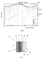
- Figure 3 shows the wall 70 of a radome according to the invention.
- the dielectric constants of the individual layers are numbered below.
- the wall 70 of the radome has an outer side A and an inner side I. Starting from the outer side A in the direction of the inner side I, the three layers 74, 72, 76 counted from the left correspond to the construction of a B sandwich (FIG. Fig. 1 b) , A core layer 72 comprising a dielectric material of a first dielectric constant is surrounded by two layers 74, 76 with a dielectric material of a second and a third dielectric constant, respectively.
- the second and third dielectric constants are not identical, it being ensured that, starting from the core layer 72, the dielectric material of the layer 76 directly adjacent to the inner side I, having a dielectric constant which is smaller than the core layer 72 the dielectric constant of the dielectric material of the core layer 72.
- the fourth and fifth layers 78, 80 of a dielectric material counted from the outside A are each an impedance transformation layer. These two layers 78, 80 of a dielectric material are only for impedance matching of incident electromagnetic waves at different angles of incidence. These layers 78, 80 of a dielectric material do not have adequate stability to support mechanical loads. These layers 78, 80 consist of HF-compatible foam materials which are open or closed-cell or syntactic. By admixture of fillers familiar to a person skilled in the art, the dielectric constant can be trimmed to the required size, ie the required value.
- the dielectric material of the fourth layer 78 and the fifth Layer 80 is the same and thus the fourth layer 78 and fifth layer 80 can be considered as a single layer.
- a radome protective layer 82 is applied on the outside A of the wall 70 of the radome.
- This protective layer 82 serves to protect the outer glass fiber / epoxy layer of the multilayer structure of the wall 70 from external influences, e.g. Corrosion etc. It is also expedient to apply a plurality of protective layers 82. These protective layers 82 should expediently be thin, preferably in the ⁇ m range, so that there are no negative properties with regard to the transmission of incident electromagnetic waves.
- On the inner side facing I layer 80 of the multi-layer structure of the wall 70 of the radome is also a thin, preferably in the micron range, protective layer 84 applied.
- the two impedance transformation layers 78, 80 are bonded together by means of an adhesive applied in a thin adhesive layer 86.
- This adhesive layer serves as a boundary layer between the two layers 78, 80 for impedance transformation.
- the adhesive layer 86 is present at an interface between the two layers for impedance transformation, with the adhesive layer 86 being deposited on opposite surfaces of the two layers 78, 80.
- This adhesive layer 86 is expediently designed in such a way that it has no or insignificant effects on the transmission behavior of the multilayer construction of the wall.
- the adhesive layer 88 which is present between the third layer 76 counted from the outside A and the first layer 78 for the impedance transformation.
- the thickness of the individual layers 72, 74, 76, 78, 80 of the wall according to the invention is constant over the length of the radome. However, it is possible that the thickness of the individual layers 72, 74, 76, 78, 80 or of all layers 72, 74, 76, 78, 80 varies in regions of large angles of incidence of the electromagnetic wave.
- Fig. 4a and 4b show correspond to the Fig. 2a and Fig. 2b Fig. 2a a representation of the transmission losses in a wall according to the invention in the multi-layer structure of a radome for transverse magnetic (TM) waves ( Fig. 4a ) and transversal electric (TE) waves ( Fig. 4b ).
- TM transverse magnetic
- TE transversal electric
Abstract
Description
Die Erfindung betrifft eine Wandung eines Radoms gemäß den Merkmalen des Patentanspruchs 1.The invention relates to a wall of a radome according to the features of patent claim 1.
Aus dem Stand der Technik sind verschiedene Konstruktionen bekannt, welche geeignet sind als Abdeckung für Mikrowellenantennen zu dienen. Ein Radom (Antennenkuppel) muss eine Wandung aufweisen, welche zum einen die Transmission elektromagnetischer Energie erlaubt, andererseits muss die Wandung des Radoms derart ausgeführt sein, dass die erforderliche strukturelle Integrität vorhanden ist und ein Mikrowellenantennensystem geschützt ist.From the prior art, various constructions are known, which are suitable to serve as a cover for microwave antennas. A radome (antenna dome) must have a wall, which on the one hand allows the transmission of electromagnetic energy, on the other hand, the wall of the radome must be designed such that the required structural integrity is present and a microwave antenna system is protected.
Ein Radom stellt im Wesentlichen ein elektromagnetisches Fenster dar, welches in jeder gewünschten Form hergestellt werden kann. Radome werden üblicherweise in bodengestützten Systemen als auch an Bord von Flugzeugen, unbemannten Fluggeräten oder anderen Fluggeräten mit Radar- oder Mikrowelleneinrichtungen genutzt.A radome is essentially an electromagnetic window that can be made in any desired shape. Radomes are commonly used in ground-based systems as well as on board aircraft, unmanned aerial vehicles or other radar or microwave-powered aircraft.
Aus
Die Wandung von einem Radom in klassischem Aufbau weist einen Einzelschichtaufbau in Form eines monolithischen Aufbaus auf. Diese Wandung zeichnet sich durch hohe Stabilität und durch ein hohes Gewicht aus. Die Einzelschicht weist üblicherweise eine homogene Dielektrizitätskonstante auf, was dazu führt, dass die Schicht und damit die Wandung des Radoms nur in einem bestimmten Frequenzbereich ausreichende transmittierende Eigenschaften aufweist. Dieser Aufbau ist für die Transmission eines breitbandigen Antennensignals nicht geeignet.The wall of a radome in a classical construction has a single layer structure in the form of a monolithic structure. This wall is characterized by high stability and high weight. The single layer usually has a homogeneous dielectric constant, which means that the layer and thus the wall of the radome has sufficient transmissive properties only in a certain frequency range. This structure is not suitable for the transmission of a broadband antenna signal.
Für den speziellen Fall von Nasenradomen an Kampfflugzeugen werden im Stand der Technik fast ausschließlich monolithische Aufbauten gewählt. Diese zeichnen sich durch ein hinreichend gutes Transmissionsverhalten im Hauptband des Primärradarsystems aus. Zukünftig werden jedoch immer mehr Sensorfunktionen in solch ein zentrales Antennen-Frontend integriert, was mit einer deutlichen Erweiterung des Frequenzbandes einhergeht. Jedoch können monolithische Radome über den typischen Frequenzbereich von 5 GHz bis hin zu 18GHz konzeptionell nicht eine gleichbleibende Transmissivität aufweisen, speziell wenn diese für alle möglichen Einfallswinkel und beide grundlegenen Polarisationen (TE - transversal elektrisch, TM - transversal magnetisch) gefordert ist.For the particular case of nose radomes on fighter aircraft, almost exclusively monolithic structures are chosen in the prior art. These are characterized by a sufficiently good transmission behavior in the main band of the primary radar system. In the future, however, more and more sensor functions will be integrated into such a central antenna frontend, which is accompanied by a significant expansion of the frequency band. However, monolithic radomes can not conceptually have consistent transmissivity over the typical 5GHz to 18GHz frequency range, especially when required for all possible angles of incidence and both fundamental polarizations (TE - transverse electric, TM - transverse magnetic).
Aufbauten im Mehrschichtaufbau erweisen sich bei der Transmission von breitbandigen Antennensignalen als vorteilhafter. Mit diesen Aufbauten ist es möglich, eine elektromagnetische Transparenz von Signalen mit einem weiten Frequenzbereich zu erzielen. Wandungen im Mehrschichtaufbau zeichnen sich im Wesentlichen dadurch aus, dass Schichten mit einer hohen Dielektrizitätskonstanten und einer niedrigen Dielektrizitätskonstanten verwendet werden. Hierbei wird zwischen verschiedenen Anordnungen unterschieden:Superstructures in multilayer construction prove to be more advantageous in the transmission of broadband antenna signals. With these structures, it is possible to achieve electromagnetic transparency of signals having a wide frequency range. Walls in the multilayer structure are characterized essentially by the fact that layers with a high dielectric constant and a low dielectric constant are used. Here, a distinction is made between different arrangements:
A-Sandwich (
B-Sandwich (
C-Sandwich (
D-Sandwich (
Der Aufbau verschiedener Wandungen, insbesondere in A- und B-SandwichBauweise ist auch aus "Ka-Band Radome Design"; PHASE REPORT AIRTASK NO. A3533E12021/RO08-01-01 Work Unit No. 48; Naval Air Development Center; 20. May 1969 bekannt.The construction of different walls, especially in A- and B-sandwich construction is also from "Ka-band Radome Design"; PHASE REPORT AIRTASK NO. A3533E12021 / RO08-01-01 Work Unit no. 48; Naval Air Development Center; May 20, 1969 known.
Ein weiterer Aufbau einer Wandung eines Radoms bei welchem mehrere Schichten eingesetzt werden ist aus
Für alle beschriebenen Wandungen (A- bis D-Sandwich) gilt, dass eine gleichbleibende elektromagnetische Transparenz im Sinne der beiden Polarisationen TE und TM nicht immer gewährleistet werden kann. Oftmals verschlechtert sich die Transparenz bei steigenden Einfallswinkeln θ innerhalb der TE-Polarisation stärker, als innerhalb der TM-Polarisation.For all described walls (A to D sandwich), it can not always be guaranteed that consistent electromagnetic transparency in terms of the two polarizations TE and TM can be guaranteed. Often, transparency increases with increasing angles of incidence θ within the TE polarization, than within the TM polarization.
Aufgabe der Erfindung ist es, eine Wandung eines Radoms anzugeben, welche über einen großen Frequenz- und Einfallswinkelbereich eine homogene und hohe Transmissivität für elektromagnetische Strahlung beider Polarisationen sicherstellt und zugleich eine hohe mechanische Stabilität aufweist.The object of the invention is to provide a wall of a radome, which ensures a homogeneous and high transmissivity for electromagnetic radiation of both polarizations over a large frequency and incident angle range and at the same time has a high mechanical stability.
Diese Aufgabe wird durch die Wandung gemäß den Merkmalen des geltenden Anspruchs 1 gelöst. Vorteilhafte Ausführungen sind Gegenstand von Unteransprüchen.This object is achieved by the wall according to the features of the current claim 1. Advantageous embodiments are the subject of dependent claims.
Die Erfindung geht aus von einer Wandung einer Antennenkuppel im Typ B-Sandwichaufbau, nämlich einer Wandung einer Antennenkuppel mit einer Innen- und einer Außenseite, wobei die Wandung eine Kernschicht aus dielektrischem Material, welche zwei Schichten aus dielektrischem Material trennt, umfasst, wobei die Dielektrizitätskonstante des dielektrischen Materials der Kernschicht größer ist als die Dielektrizitätskonstante des dielektrischen Materials der zwei Schichten. Die Erfindung zeichnet sich dadurch aus, dass auf der der Innenseite der Wandung zugewandten Schicht zwei weitere Schichten zur Impedanztransformation aus dielektrischem Material angeordnet sind. Deren Dielektrizitätskonstanten sind so gewählt, dass sich Schicht um Schicht ein von der Kernschicht ausgehender, in Richtung auf die Innenseite fortschreitender Abfall der Dielektrizitätskonstante ergibt.The invention is based on a wall of a type B sandwich antenna dome, namely a wall of an antenna dome having an inside and an outside, the wall comprising a core layer of dielectric material separating two layers of dielectric material, the dielectric constant of the dielectric material of the core layer is larger than the dielectric constant of the dielectric material of the two layers. The invention is characterized in that two further layers for impedance transformation of dielectric material are arranged on the layer facing the inside of the wall. Their dielectric constants are selected such that, layer by layer, a drop in the dielectric constant proceeding from the core layer and progressing towards the inside results.
In einer bevorzugten Ausführungsform der Erfindung beträgt die Dielektrizitätskonstante des dielektrischen Materials der Kernschicht zwischen 4,5 und 6,0, wobei die Dielektrizitätskonstante des dielektrischen Materials der zwei durch die Kernschicht getrennten Schichten zwischen 2,8 und 3,5 liegt. Zweckmäßig ist die Dielektrizitätskonstante des dielektrischen Materials dieser zwei Schichten unterschiedlich.In a preferred embodiment of the invention, the dielectric constant of the dielectric material of the core layer is between 4.5 and 6.0, wherein the dielectric constant of the dielectric material of the two layers separated by the core layer is between 2.8 and 3.5. Suitably, the dielectric constant of the dielectric material of these two layers is different.
Der erfindungsgemäße Mehrschichtaufbau zeichnet sich dadurch aus, dass sich an seiner Außenseite drei massive Schichten befinden, welche in ihrer Summe einem quasi-monolithischen Aufbau ähneln, was die mechanische Festigkeit und Belastbarkeit betrifft. In diesem Sinne ist es mit dem erfindungsgemäßen Schichtaufbau nicht nötig, Einschränkungen hinsichtlich der in der Vergangenheit akzeptieren Radom-Parameter zu treffen. Diese drei massiven Schichten dienen im Wesentlichen zum Tragen von mechanischen Lasten.The multilayer structure according to the invention is characterized in that on its outside are three massive layers, which in their sum resemble a quasi-monolithic structure, which relates to the mechanical strength and resilience. In this sense, with the layer structure according to the invention, it is not necessary to impose restrictions with regard to the radome parameters accepted in the past. These three massive layers essentially serve to carry mechanical loads.
In einer weiteren bevorzugten Ausführungsform der Erfindung umfasst die Kernschicht ein Kunstharz mit E- oder S2-Glasfasern. E-Glasfasern sind aus dem Stand der Technik bekannt. Für die Kunststoffverstärkung haben E-Glasfasern große Bedeutung erlangt. E steht für Elektro-Glas, da es ursprünglich vor allem in der Elektroindustrie eingesetzt wurde. Für die Produktion von E-Glas werden Glasschmelzen aus reinem Quarz mit Zusätzen aus Kalkstein, Kaolin und Borsäure hergestellt. Sie enthalten neben SiO2 (Siliciumdioxid) unterschiedliche Mengen verschiedener Metalloxide. Die Zusammensetzung bestimmt die Eigenschaften der Produkte. S2-Glasfasern zeichnen sich durch erhöhte Steifigkeit aus.In a further preferred embodiment of the invention, the core layer comprises a synthetic resin with E or S2 glass fibers. E-glass fibers are known in the art. For the plastic reinforcement E-glass fibers have gained great importance. E stands for electro-glass, since it was originally mainly in the electrical industry was used. For the production of E-glass, pure quartz glass melts are made with additions of limestone, kaolin and boric acid. In addition to SiO2 (silicon dioxide), they contain different amounts of different metal oxides. The composition determines the properties of the products. S2 glass fibers are characterized by increased rigidity.
In einer weiteren bevorzugten Ausführungsform der Erfindung umfasst die zwei durch die Kernschicht getrennten Schichten ein Kunstharz mit Quarzglasfasern, wobei in einer zweckmäßigen Ausgestaltungsform das Kunstharz der Kernschicht und das Kunstharz der zwei durch die Kernschicht getrennten Schichten gleich ist.In a further preferred embodiment of the invention, the two layers separated by the core layer comprise a synthetic resin with quartz glass fibers, in one expedient embodiment the synthetic resin of the core layer and the synthetic resin of the two layers separated by the core layer being identical.
In einer weiteren bevorzugten Ausführungsform der Erfindung sind die Dielektrizitätskonstanten der dielektrischen Materialien der zwei weiteren Schichten zur Impendanztransformation kleiner als die Dielektrizitätskonstanten der dielektrischen Materialien beider durch die Kernschicht getrennten Schichten. Zweckmä-βig sind die Dielektrizitätskonstanten dieser beiden Schichten zur Impedanztransformation derart gewählt, dass die Dielektrizitätskonstante der näher zur Außenseite der Wandung liegenden Transformationsschicht zwischen 1,4 und 1,6 liegt und die Dielektrizitätskonstante der näher zur Innenseite der Wandung liegenden Transformationsschicht zwischen 1,05 und 1,2 liegt.In a further preferred embodiment of the invention, the dielectric constants of the dielectric materials of the two further layers for impedance transformation are smaller than the dielectric constants of the dielectric materials in the layers separated by the core layer. Expediently, the dielectric constants of these two impedance-transformation layers are selected such that the dielectric constant of the transformation layer closer to the outside of the wall lies between 1.4 and 1.6, and the dielectric constant of the transformation layer closer to the inside of the wall is between 1.05 and 1.05 1,2 is located.
Die zwei zuletzt beschriebenen dielektrischen Schichten tragen in keiner Weise mechanische Lasten. Sie dienen ausschließlich der Impedanzanpassung von einfallenden elektromagnetischen Wellen unter verschiedenen Einfallswinkeln. Zweckmäßig werden solche Schichten aus Hochfrequenz-Schaummaterialien hergestellt, welche in ihrer dielektrischen Konstante beeinflussbar sind, z.B. durch das Zugeben von Füllstoffen. Speziell die Verwendung von syntaktischen Schäumen ist hier von Vorteil.The two last-described dielectric layers in no way bear mechanical loads. They serve exclusively for the impedance matching of incident electromagnetic waves at different angles of incidence. Conveniently, such layers are made from high frequency foam materials which are influenced in their dielectric constant, e.g. by adding fillers. Especially the use of syntactic foams is an advantage here.
In einer weiteren bevorzugten Ausführungsform umfassen die Schichten zur Impedanztransformation die Verwendung von hochfrequenztauglichen offenzelligen, geschlossenzellig, oder syntaktischen Schaummaterialien, wobei diese durch Beimengung von Füllstoffen auf eine erforderliche Größe der Dielektrizitätskonstante getrimmt sind.In a further preferred embodiment, the impedance transformation layers comprise the use of high-frequency open-cell, closed-cell, or syntactic foam materials Addition of fillers trimmed to a required size of the dielectric constant.
Der Schichtaufbau der erfindungsgemäßen Wandung für eine Antennenkuppel ähnelt, wie bereits oben beschrieben, formal dem eines B-Sandwichs. Allerdings ist der dielektrische Kontrast zwischen den, dem Tragen von Lasten dienenden drei beteiligten Kunstharz/Glasfaser-Schichten nicht sehr hoch, so dass die gesamte Struktur mit der Kernschicht und der beiden benachbarten Schichten aus einer einzigen Kunstharz-Sorte und zwei verschiedenen Glasfasersorten (z.B. Quarzglas und E-Glas) realisiert werden kann. Die Verwendung von nur einem Harzsystem vereinfacht die mechanische Kompatibilität in Bezug auf thermische Ausdehnung und sonstige Scherkräfte.The layer structure of the wall according to the invention for an antenna dome, as already described above, is formally similar to that of a B sandwich. However, the dielectric contrast between the three loaded resin / fiber layers involved in carrying loads is not very high, so that the entire structure with the core layer and the two adjacent layers consists of a single resin grade and two different types of glass fiber (eg quartz glass and E-glass) can be realized. The use of only one resin system simplifies mechanical compatibility with respect to thermal expansion and other shear forces.
Wie schon erwähnt erfolgt die Realisierung der erfindungsgemäßen Wandung mit seinen Schichten über verschiedene Glasfaser-Sorten zusammen mit einem einzigen passenden Harzsystem. Es liegt im fachmännischen Können, ein passendes Harzsystem zu wählen. Auf Grund dieser Konfiguration kann der B-Sandwich-artige Aufbau der Wandung in einem Schritt z.B. durch Harzinfiltrationsverfahren erfolgen, so dass ein zusammenhängender Block entsteht, der in seinem Aufbau die notwendige Abstufung der dielektrischen Konstanten beinhaltet.As already mentioned, the realization of the wall according to the invention with its layers takes place via different types of glass fibers together with a single suitable resin system. It is up to the expert to choose a suitable resin system. Due to this configuration, the B-sandwich-like construction of the wall can be done in one step e.g. by Harzinfiltrationsverfahren so that a coherent block is formed, which includes in its structure the necessary gradation of the dielectric constant.
Es ist noch darauf hinzuweisen, dass die Dicke aller Schichten zusammen über die gesamte Fläche des Radoms konstant ausgebildet sein kann. Es sind aber auch Ausführungen möglich, in welcher diese Dicke zumindest abschnittsweise unterschiedlich gewählt wird. Eine solche Veränderung in der Gesamtdicke der Schichten kann insbesondere in Abhängigkeit von der Längsachse des Radoms von Vorteil sein.It should also be pointed out that the thickness of all the layers together can be made constant over the entire surface of the radome. However, embodiments are also possible in which this thickness is selected differently, at least in sections. Such a change in the total thickness of the layers may be particularly advantageous depending on the longitudinal axis of the radome.
Die Erfindung sowie weitere vorteilhafte Ausführungsformen werden im Weiteren anhand von Figuren näher erläutert. Es zeigen:
- Fig. 1a
- eine Wandung im A-Sandwichaufbau gemäß dem Stand der Technik,
- Fig. 1b
- eine Wandung im B-Sandwichaufbau gemäß dem Stand der Technik,
- Fig. 1c
- eine Wandung im C-Sandwichaufbau gemäß dem Stand der Technik,
- Fig. 1d
- eine Wandung im D-Sandwichaufbau gemäß dem Stand der Technik,
- Fig. 2a
- eine beispielhafte Darstellung der Transmissionsverluste bei einer monolithische Wandung für Transversal-Magnetisch-(TM-) Wellen nach dem Stand der Technik,
- Fig. 2b
- eine beispielhafte Darstellung der Transmissionsverluste bei einer monolithische Wandung für Transversal-Elektrisch-(TE-) Wellen nach dem Stand der Technik,
- Fig. 3
- eine Wandung in Mehrschichtaufbau gemäß der Erfindung,
- Fig. 4a
- eine beispielhafte Darstellung der Transmissionsverluste bei einer erfindungsgemäßen Wandung für Transversal-Magnetisch-(TM-) Wellen,
- Fig. 4b
- eine beispielhafte Darstellung der Transmissionsverluste bei einer erfindungsgemäßen Wandung für Transversal-Elektrisch-(TE-) Wellen.
- Fig. 1a
- a wall in the A-sandwich construction according to the prior art,
- Fig. 1b
- a wall in the B-sandwich construction according to the prior art,
- Fig. 1c
- a wall in C sandwich construction according to the prior art,
- Fig. 1d
- a wall in the D-sandwich construction according to the prior art,
- Fig. 2a
- an exemplary representation of the transmission losses in a monolithic wall for transverse magnetic (TM) waves according to the prior art,
- Fig. 2b
- an exemplary representation of the transmission losses in a monolithic wall for transversal electrical (TE) waves according to the prior art,
- Fig. 3
- a wall in multilayer construction according to the invention,
- Fig. 4a
- an exemplary representation of the transmission losses in a wall according to the invention for transverse magnetic (TM) waves,
- Fig. 4b
- an exemplary representation of the transmission losses in a wall according to the invention for transverse electric (TE) waves.
Die Wandung 70 des Radoms weist eine Außenseite A und eine Innenseite I auf. Ausgehend von der Außenseite A in Richtung der Innenseite I entsprechen die drei von links gezählten Schichten 74, 72, 76 dem aus dem Stand der Technik bekannten Aufbau eines B-Sandwich (
Die von der Außenseite A gezählte vierte und fünfte Schicht 78, 80 eines dielektrischen Materials ist jeweils eine Schicht zur Impedanztransformation. Diese beiden Schichten 78, 80 eines dielektrischen Materials dienen nur der Impedanzanspassung von einfallenden elektromagnetischen Wellen unter verschiedenen Einfallswinkeln. Diese Schichten 78, 80 eines dielektrischen Materials weisen keine entsprechende Stabilität auf, um mechanische Lasten zu tragen. Diese Schichten 78, 80 bestehen aus HF-tauglichen Schaummaterialien, welche offen- oder geschlossenzellig oder syntaktisch sind. Durch Beimengung von einem Fachmann geläufigen Füllstoffen kann die Dielektrizitätskonstante auf die erforderliche Größe, d.h. den erforderliche Wert getrimmt, also eingestellt werden. Zweckmäßig weist das dielektrische Material der vierten Schicht 78 eine Dielektrizitätskonstante er=1,5 und das dielektrische Material der fünften Schicht 80 eine Dielektrizitätskonstante er=1,1 auf. Es ist aber auch möglich, dass in einer bevorzugten Ausführungsform das dielektrische Material der vierten Schicht 78 und der fünften Schicht 80 gleich ist und somit die vierte Schicht 78 und fünfte Schicht 80 als eine einzelne Schicht betrachtet werden kann.The fourth and
Auf der Außenseite A der Wandung 70 des Radoms ist eine Radom-Schutzschicht 82 aufgebracht. Diese Schutzschicht 82 dient dazu, die äußere Glasfaser/Epoxy-Schicht des Mehrschichtaufbaus der Wandung 70 vor äußeren Einflüssen zu schützen, z.B. Korrosion etc. Zweckmäßig können auch mehrere Schutzschichten 82 aufgetragen sein. Diese Schutzschichten 82 sollten zweckmäßig dünn sein, vorzugsweise im µm-Bereich, so dass es zu keinen negativen Eigenschaften bezüglich der Transmission einfallender elektromagnetischer Wellen kommt. Auf der der Innenseite I zugewandten Schicht 80 des Mehrschichtaufbaus der Wandung 70 des Radoms ist ebenfalls eine dünne, vorzugsweise im µm-Bereich, Schutzschicht 84 aufgetragen.On the outside A of the
Die beiden Schichten 78, 80 zur Impedanztransformation sind mittels eines in einer dünnen Klebeschicht 86 aufgetragenem Kleber miteinander verbunden. Diese Klebeschicht dient als Grenzschicht zwischen den beiden Schichten 78, 80 zur Impedanztransformation. Die Klebeschicht 86 ist an einer Grenzfläche zwischen den beiden Schichten zur Impedanztransformation vorhanden, wobei die Klebeschicht 86 auf zueinander gegenüberliegenden Oberflächen der beiden Schichten 78, 80 aufgetragen ist. Diese Klebeschicht 86 ist zweckmäßig derart gestaltet, dass sie keine bzw. unwesentliche Auswirkungen auf das Transmissionsverhalten des Mehrlagenaufbaus der Wandung zeigt. Gleiches soll in analoger Weise für die Klebeschicht 88 gelten, die zwischen der von der Außenseite A gezählt, dritten Schicht 76 und der ersten Schicht 78 zur Impedanztransformation vorhanden ist.The two impedance transformation layers 78, 80 are bonded together by means of an adhesive applied in a thin
Die Dicke der einzelnen Schichten 72, 74, 76, 78, 80 der erfindungsgemäßen Wandung ist über die Längenausdehnung des Radoms hinweg konstant. Es ist aber möglich, dass in Bereichen großer Einfallswinkel der elektromagnetischen Welle die Dicke der einzelnen Schichten 72, 74, 76, 78, 80 oder aller Schichten 72, 74, 76, 78, 80 variiert.The thickness of the
Die
Auf
Claims (14)
Priority Applications (1)
| Application Number | Priority Date | Filing Date | Title |
|---|---|---|---|
| EP12008394.4A EP2747202A1 (en) | 2012-12-18 | 2012-12-18 | Radome wall |
Applications Claiming Priority (1)
| Application Number | Priority Date | Filing Date | Title |
|---|---|---|---|
| EP12008394.4A EP2747202A1 (en) | 2012-12-18 | 2012-12-18 | Radome wall |
Publications (1)
| Publication Number | Publication Date |
|---|---|
| EP2747202A1 true EP2747202A1 (en) | 2014-06-25 |
Family
ID=47605264
Family Applications (1)
| Application Number | Title | Priority Date | Filing Date |
|---|---|---|---|
| EP12008394.4A Withdrawn EP2747202A1 (en) | 2012-12-18 | 2012-12-18 | Radome wall |
Country Status (1)
| Country | Link |
|---|---|
| EP (1) | EP2747202A1 (en) |
Cited By (6)
| Publication number | Priority date | Publication date | Assignee | Title |
|---|---|---|---|---|
| WO2018077823A1 (en) | 2016-10-27 | 2018-05-03 | Lufthansa Technik Ag | Radome wall for communication applications |
| CN108258411A (en) * | 2018-01-25 | 2018-07-06 | 合肥驼峰电子科技发展有限公司 | A kind of radome based on high strength composite |
| WO2021000704A1 (en) * | 2019-06-30 | 2021-01-07 | Oppo广东移动通信有限公司 | Housing assembly, antenna apparatus, and electronic device |
| KR20210109002A (en) * | 2018-12-27 | 2021-09-03 | 생-고뱅 퍼포먼스 플라스틱스 코포레이션 | Broadband radome design |
| KR20220088936A (en) * | 2019-12-30 | 2022-06-28 | 생-고뱅 퍼포먼스 플라스틱스 코포레이션 | radome design |
| US20220311134A1 (en) * | 2021-03-25 | 2022-09-29 | Airbus Defence and Space GmbH | Asymmetrically Constructed Radome |
Citations (9)
| Publication number | Priority date | Publication date | Assignee | Title |
|---|---|---|---|---|
| DE2441540A1 (en) * | 1974-08-30 | 1976-03-11 | Deutsche Bundespost | Self-supporting dielectric cover for microwave aerials - has low reflection coefficient over wide range of wavelengths |
| US4783666A (en) * | 1987-05-21 | 1988-11-08 | General Electric Company | Protective shield for an antenna array |
| EP0420137A2 (en) * | 1989-09-26 | 1991-04-03 | Hughes Aircraft Company | Two layer matching dielectrics for radomes and lenses for wide angles of incidence |
| US5408244A (en) | 1991-01-14 | 1995-04-18 | Norton Company | Radome wall design having broadband and mm-wave characteristics |
| EP0843379A2 (en) | 1996-11-19 | 1998-05-20 | Norton Performance Plastics Corporation | W-band and X-band radome wall |
| DE20219029U1 (en) * | 2002-12-04 | 2003-02-20 | Fus Torsten | Reflection optimized antenna cladding for microwave range |
| US20040246194A1 (en) * | 2003-06-09 | 2004-12-09 | Mitsubishi Denki Kabushiki Kaisha | Radome |
| US20080136731A1 (en) * | 2005-12-08 | 2008-06-12 | Raytheon Company | Broadband ballistic resistant radome |
| US20100103072A1 (en) * | 2008-10-24 | 2010-04-29 | Kuang-Yuh Wu | Honey Comb-Backed Armored Radome |
-
2012
- 2012-12-18 EP EP12008394.4A patent/EP2747202A1/en not_active Withdrawn
Patent Citations (9)
| Publication number | Priority date | Publication date | Assignee | Title |
|---|---|---|---|---|
| DE2441540A1 (en) * | 1974-08-30 | 1976-03-11 | Deutsche Bundespost | Self-supporting dielectric cover for microwave aerials - has low reflection coefficient over wide range of wavelengths |
| US4783666A (en) * | 1987-05-21 | 1988-11-08 | General Electric Company | Protective shield for an antenna array |
| EP0420137A2 (en) * | 1989-09-26 | 1991-04-03 | Hughes Aircraft Company | Two layer matching dielectrics for radomes and lenses for wide angles of incidence |
| US5408244A (en) | 1991-01-14 | 1995-04-18 | Norton Company | Radome wall design having broadband and mm-wave characteristics |
| EP0843379A2 (en) | 1996-11-19 | 1998-05-20 | Norton Performance Plastics Corporation | W-band and X-band radome wall |
| DE20219029U1 (en) * | 2002-12-04 | 2003-02-20 | Fus Torsten | Reflection optimized antenna cladding for microwave range |
| US20040246194A1 (en) * | 2003-06-09 | 2004-12-09 | Mitsubishi Denki Kabushiki Kaisha | Radome |
| US20080136731A1 (en) * | 2005-12-08 | 2008-06-12 | Raytheon Company | Broadband ballistic resistant radome |
| US20100103072A1 (en) * | 2008-10-24 | 2010-04-29 | Kuang-Yuh Wu | Honey Comb-Backed Armored Radome |
Cited By (13)
| Publication number | Priority date | Publication date | Assignee | Title |
|---|---|---|---|---|
| WO2018077823A1 (en) | 2016-10-27 | 2018-05-03 | Lufthansa Technik Ag | Radome wall for communication applications |
| DE102016221143A1 (en) | 2016-10-27 | 2018-05-03 | Lufthansa Technik Ag | Radome wall for communication applications |
| DE102016221143B4 (en) | 2016-10-27 | 2018-05-09 | Lufthansa Technik Ag | Radome wall for communication applications |
| EP4009440A1 (en) | 2016-10-27 | 2022-06-08 | Lufthansa Technik AG | Radome wall for communication applications |
| US11095025B2 (en) | 2016-10-27 | 2021-08-17 | Lufthansa Technik Ag | Radome wall for communication applications |
| CN108258411A (en) * | 2018-01-25 | 2018-07-06 | 合肥驼峰电子科技发展有限公司 | A kind of radome based on high strength composite |
| KR20210109002A (en) * | 2018-12-27 | 2021-09-03 | 생-고뱅 퍼포먼스 플라스틱스 코포레이션 | Broadband radome design |
| JP2022515525A (en) * | 2018-12-27 | 2022-02-18 | サン-ゴバン パフォーマンス プラスティックス コーポレイション | Wideband radome design |
| WO2021000704A1 (en) * | 2019-06-30 | 2021-01-07 | Oppo广东移动通信有限公司 | Housing assembly, antenna apparatus, and electronic device |
| KR20220088936A (en) * | 2019-12-30 | 2022-06-28 | 생-고뱅 퍼포먼스 플라스틱스 코포레이션 | radome design |
| US11380984B2 (en) | 2019-12-30 | 2022-07-05 | Saint-Gobain Performance Plastics Corporation | Radome design |
| US20220311134A1 (en) * | 2021-03-25 | 2022-09-29 | Airbus Defence and Space GmbH | Asymmetrically Constructed Radome |
| US11777203B2 (en) * | 2021-03-25 | 2023-10-03 | Airbus Defence and Space GmbH | Asymmetrically constructed radome |
Similar Documents
| Publication | Publication Date | Title |
|---|---|---|
| EP2747202A1 (en) | Radome wall | |
| DE2600138C2 (en) | Device based on surface acoustic waves with a carrier body made of piezoelectric material and used for the transmission of surface acoustic waves and a method for their production | |
| DE2211438C3 (en) | Covering for antennas | |
| DE3023562C2 (en) | Device for polarization conversion of electromagnetic waves | |
| DE102016101583B4 (en) | Radom | |
| EP1754284A1 (en) | Waveguide structure | |
| EP4009440B1 (en) | Radome wall for communication applications | |
| DE3534059C1 (en) | Fibre composite material | |
| DE2136918A1 (en) | Antenna with adjustable bundling angle | |
| DE2753180A1 (en) | CIRCULAR ANTENNA | |
| DE3722793A1 (en) | WHEEL ARM MATERIAL | |
| DE69836457T2 (en) | PLATES AND MATERIAL FOR THE ABSORBENT OF ELECTROMAGNETIC WAVES | |
| DE2441540C3 (en) | Self-supporting, low reflection, dielectric cover for microwave antennas | |
| DE2800266A1 (en) | COMPENSATION ARRANGEMENT FOR TWO RELATIVELY TWISTED SEMICONDUCTORS | |
| DE3700886A1 (en) | SEMICONDUCTOR SLOT AERIAL FOR DOPPLER NAVIGATORS | |
| DE19902511C2 (en) | Linings for directional antennas | |
| EP0443564A2 (en) | Absorber for electromagnetic waves | |
| DE202022101604U1 (en) | Inlay for metal doors | |
| EP2461023B1 (en) | Rotor blade for a wind turbine and combination of a radar station and wind turbine | |
| DE3812029C2 (en) | Wall for antenna dome and antenna domes made with it | |
| EP0309850B1 (en) | Spurious electromagnetic-mode suppression arrangement in a waveguide installation | |
| DE4234486C1 (en) | Arrangement for splitting an optical input signal into two signals with mutually orthogonal polarization | |
| DE112018007136T5 (en) | RADAR DEVICE | |
| EP1303003B1 (en) | Protective covering for radio systems, components thereof, and methods of fabrication | |
| DE2811750A1 (en) | HIGHEST FREQUENCY PHASE SHIFT |
Legal Events
| Date | Code | Title | Description |
|---|---|---|---|
| PUAI | Public reference made under article 153(3) epc to a published international application that has entered the european phase |
Free format text: ORIGINAL CODE: 0009012 |
|
| 17P | Request for examination filed |
Effective date: 20121218 |
|
| AK | Designated contracting states |
Kind code of ref document: A1 Designated state(s): AL AT BE BG CH CY CZ DE DK EE ES FI FR GB GR HR HU IE IS IT LI LT LU LV MC MK MT NL NO PL PT RO RS SE SI SK SM TR |
|
| AX | Request for extension of the european patent |
Extension state: BA ME |
|
| STAA | Information on the status of an ep patent application or granted ep patent |
Free format text: STATUS: THE APPLICATION IS DEEMED TO BE WITHDRAWN |
|
| 18D | Application deemed to be withdrawn |
Effective date: 20150106 |