EP2745858A1 - Homecare suction device - Google Patents
Homecare suction device Download PDFInfo
- Publication number
- EP2745858A1 EP2745858A1 EP13159711.4A EP13159711A EP2745858A1 EP 2745858 A1 EP2745858 A1 EP 2745858A1 EP 13159711 A EP13159711 A EP 13159711A EP 2745858 A1 EP2745858 A1 EP 2745858A1
- Authority
- EP
- European Patent Office
- Prior art keywords
- air
- container
- air inlet
- homecare
- suction device
- Prior art date
- Legal status (The legal status is an assumption and is not a legal conclusion. Google has not performed a legal analysis and makes no representation as to the accuracy of the status listed.)
- Withdrawn
Links
Images


Classifications
-
- A—HUMAN NECESSITIES
- A61—MEDICAL OR VETERINARY SCIENCE; HYGIENE
- A61M—DEVICES FOR INTRODUCING MEDIA INTO, OR ONTO, THE BODY; DEVICES FOR TRANSDUCING BODY MEDIA OR FOR TAKING MEDIA FROM THE BODY; DEVICES FOR PRODUCING OR ENDING SLEEP OR STUPOR
- A61M11/00—Sprayers or atomisers specially adapted for therapeutic purposes
- A61M11/06—Sprayers or atomisers specially adapted for therapeutic purposes of the injector type
-
- A—HUMAN NECESSITIES
- A61—MEDICAL OR VETERINARY SCIENCE; HYGIENE
- A61B—DIAGNOSIS; SURGERY; IDENTIFICATION
- A61B17/00—Surgical instruments, devices or methods, e.g. tourniquets
- A61B17/24—Surgical instruments, devices or methods, e.g. tourniquets for use in the oral cavity, larynx, bronchial passages or nose; Tongue scrapers
-
- A—HUMAN NECESSITIES
- A61—MEDICAL OR VETERINARY SCIENCE; HYGIENE
- A61M—DEVICES FOR INTRODUCING MEDIA INTO, OR ONTO, THE BODY; DEVICES FOR TRANSDUCING BODY MEDIA OR FOR TAKING MEDIA FROM THE BODY; DEVICES FOR PRODUCING OR ENDING SLEEP OR STUPOR
- A61M1/00—Suction or pumping devices for medical purposes; Devices for carrying-off, for treatment of, or for carrying-over, body-liquids; Drainage systems
- A61M1/06—Milking pumps
-
- A—HUMAN NECESSITIES
- A61—MEDICAL OR VETERINARY SCIENCE; HYGIENE
- A61M—DEVICES FOR INTRODUCING MEDIA INTO, OR ONTO, THE BODY; DEVICES FOR TRANSDUCING BODY MEDIA OR FOR TAKING MEDIA FROM THE BODY; DEVICES FOR PRODUCING OR ENDING SLEEP OR STUPOR
- A61M1/00—Suction or pumping devices for medical purposes; Devices for carrying-off, for treatment of, or for carrying-over, body-liquids; Drainage systems
- A61M1/71—Suction drainage systems
- A61M1/74—Suction control
-
- A—HUMAN NECESSITIES
- A61—MEDICAL OR VETERINARY SCIENCE; HYGIENE
- A61B—DIAGNOSIS; SURGERY; IDENTIFICATION
- A61B17/00—Surgical instruments, devices or methods, e.g. tourniquets
- A61B17/24—Surgical instruments, devices or methods, e.g. tourniquets for use in the oral cavity, larynx, bronchial passages or nose; Tongue scrapers
- A61B2017/246—Surgical instruments, devices or methods, e.g. tourniquets for use in the oral cavity, larynx, bronchial passages or nose; Tongue scrapers for cleaning of the nose
-
- A—HUMAN NECESSITIES
- A61—MEDICAL OR VETERINARY SCIENCE; HYGIENE
- A61M—DEVICES FOR INTRODUCING MEDIA INTO, OR ONTO, THE BODY; DEVICES FOR TRANSDUCING BODY MEDIA OR FOR TAKING MEDIA FROM THE BODY; DEVICES FOR PRODUCING OR ENDING SLEEP OR STUPOR
- A61M15/00—Inhalators
- A61M15/0001—Details of inhalators; Constructional features thereof
- A61M15/0021—Mouthpieces therefor
-
- A—HUMAN NECESSITIES
- A61—MEDICAL OR VETERINARY SCIENCE; HYGIENE
- A61M—DEVICES FOR INTRODUCING MEDIA INTO, OR ONTO, THE BODY; DEVICES FOR TRANSDUCING BODY MEDIA OR FOR TAKING MEDIA FROM THE BODY; DEVICES FOR PRODUCING OR ENDING SLEEP OR STUPOR
- A61M2205/00—General characteristics of the apparatus
- A61M2205/27—General characteristics of the apparatus preventing use
- A61M2205/276—General characteristics of the apparatus preventing use preventing unwanted use
Definitions
- the present invention relates to a homecare suction device and, more particularly, to a homecare suction device including a main body and a breast pump.
- a suction device generally includes a main body having an air inlet or an air outlet for sucking or injecting purposes.
- the suction device can be used in medical treatments, such as medical care of nasal cavities and throats of patients in ear-nose-throat departments of hospitals and elderly healthcare centers.
- a nasal mucus sucker can be used with the main body of the suction device to suck nasal mucus and accumulated phlegm out of the nasal cavity of a patient.
- an injector or nasal spray
- a sprayer can be used with the main body to proceed with spray treatment in the nasal cavity or throat.
- a breast pump for sucking breast milk operates under a suction force.
- a large space will be occupied if a main body is attached to each of the nasal mucus sucker, the injector, the sprayer, and the breast pump.
- a breast pump is generally connected to a container for receiving breast milk.
- a negative pressure will be generated in the breast pump and an interior of the container if no ventilation device is provided in the breast pump or the container.
- the breast milk will be sucked into an air pump in the main body of the suction device if the negative pressure is too large, adversely affecting operation of the air pump and shortening the service life of the main body.
- a homecare suction device includes a main body having a housing.
- An air pump is mounted in the housing.
- the housing includes an air outlet and an air inlet.
- the air pump is in communication with the air outlet and the air inlet.
- a container includes an opening.
- the container is adapted to receive a liquid.
- a breast pump includes a cover mounted to the opening of the container.
- the cover includes a liquid sucking unit and an air sucking unit.
- Each of the liquid sucking unit and the air sucking unit is in communication with an interior of the container.
- the liquid sucking unit includes a liquid passage and a cup.
- the cup is adapted to contact with an object.
- the air sucking unit includes an air passage and a connection port in communication with the air inlet of the main body.
- a funnel is mounted in the cover and in communication with the liquid passage, the air passage, and the interior of the container.
- the cover further includes a vent communicating the interior of the container with the outside, preventing generation of an excessive negative pressure in the container to avoid the liquid in the container from being sucked into the air passage.
- a hose includes two ends respectively connected to the air inlet and the connection port.
- the hose connected between the air inlet and the connection port allows easy detachment of the breast pump from the main body, allowing use of the main body with a device requiring suction, injection, or atomization.
- Due to provision of the funnel between the cover and the opening of the container the liquid from the breast pump can flow through the liquid passage and the funnel into the container in which the liquid can be stored. Since the air pump continuously draws air to suck the liquid, a sucking force is applied to the object during operation of the air pump because the air passage is also in communication with the interior of the container via the funnel. Namely, the air in the container is sucked out and generates a negative pressure in the container.
- a homecare suction device A includes a main body 1 having a housing 11.
- An air pump 12 is mounted in the housing 11.
- the housing 11 includes an air outlet 142 and an air inlet 144.
- the air pump 12 is in communication with the air outlet 142 and the air inlet 144.
- the homecare suction device A further includes a container 2 having an opening 21.
- the container 2 is adapted to receive a liquid 9.
- the container 2 is supported on a base 22.
- the homecare suction device A further includes a breast pump 3 having a cover 31 mounted to the opening 21 of the container 2.
- the cover 31 and the opening 21 of the container 2 are connected by threading connection.
- the cover 31 includes a liquid sucking unit 32 and an air sucking unit 33.
- Each of the liquid sucking unit 32 and the air sucking unit 33 is in communication with an interior of the container 2.
- the liquid sucking unit 32 includes a liquid passage 321 and a cup 322.
- the cup 322 is adapted to contact with an object 8.
- the liquid sucking unit 32 is trumpet-shaped, and a soft rubber pad 323 is mounted to a surface of the cup 322.
- the air sucking unit 33 includes an air passage 331 and a connection port 332 in communication with the air inlet 144 of the main body 1.
- the air sucking unit 33 further includes a control switch 333 for controlling a suction force of the air sucking unit 33, which is known in the art.
- a funnel 311 is mounted in the cover 31 and in communication with the liquid passage 321, the air passage 331, and the interior of the container 2.
- the funnel 311 tapers downward and is located between the cover 31 and the opening 21 of the container 2.
- the funnel 311 is made of soft rubber.
- the cover 31 further includes a vent 312 communicating the interior of the container 2 with the outside, preventing generation of an excessive negative pressure in the container 2 to avoid the liquid 9 in the container 2 from being sucked into the air passage 331.
- the homecare suction device A further includes a hose 4 having two ends respectively connected to the air inlet 144 and the connection port 332.
- a hose 4 having two ends respectively connected to the air inlet 144 and the connection port 332.
- the air inlet 144 is connected by the hose 4 to a nasal mucus sucker 5.
- the nasal mucus sucker 5 includes a nasal suction tube 51 and a control hole 52.
- the air inlet 144 is connected by the hose 4 to a sprayer 6 with a mask 61 for medical treatment of a nasal cavity of a patient.
- the air inlet 144 is connected by the hose 4 to a sprayer 6 with a mouth-biting portion 62 for medical treatment of a throat of a patient.
- FIG. 6 the air inlet 144 is connected by the hose 4 to a sprayer 6 with a mouth-biting portion 62 for medical treatment of a throat of a patient.
- the air inlet 144 is connected by the hose 4 to an injector 7 including an injection tube 71 and a control hole 72.
- an injector 7 including an injection tube 71 and a control hole 72.
- the funnel 311 is in communication with the liquid passage 321, the air passage 331, and the container 2, the liquid 9 from the breast pump 3 can flow through the liquid passage 321 and the funnel 311 into the container 2 in which the liquid 9 can be stored. Since the air pump 12 continuously draws air to suck the liquid 9, a sucking force is applied to the object 8 during operation of the air pump 12 because the air passage 331 is also in communication with the interior of the container 2 via the funnel 311. Namely, the air in the container 2 is sucked out and generates a negative pressure in the container 2. When the negative pressure in the container 2 becomes too large, the liquid 9 in the container 2 will be sucked into the air passage 331 via the funnel 311, causing damage to the air pump 12.
- vent 312 of the cover 31 communicating the interior of the container 2 with the outside avoids excessive negative pressure in the container 2, avoiding the liquid 9 in the container 2 from entering the air pump 12 via the air passage 331, maintaining normal operation of the air pump 12 and prolonging the service life of the air pump 12.
- the housing 11 includes an upper housing 111, a lower housing 112, and a connection portion 13 sandwiched between the upper and lower housings 111 and 112.
- the connection portion 13 includes a board 14.
- An air outlet tube 141 and a first air inlet tube 143 extend through the board 14.
- the air outlet tube 141 includes the air outlet 142.
- the first air inlet tube 143 includes the air inlet 144.
- An annular flange 145 is formed around a top end of the first air inlet tube 143.
- An annular wall 146 is formed around the annular flange 145.
- An annular groove is defined between the annular flange 145 and the annular wall 146.
- Filter cotton 147 is mounted in the annular flange 145 and covers the top end of the first air inlet tube 143.
- a seal ring 148 is mounted in the annular groove.
- An inlet coupler 15 is mounted in the annular wall 146.
- the inlet coupler 15 includes a second air inlet tube 152 and an annular outer wall 151 surrounding the second air inlet tube 152.
- the second air inlet tube 152 is in communication with the first air inlet tube 143.
- Air is filtered by the filter cotton 147 before entering the air pump 12, avoiding accumulation of dirt or bacteria and keeping the air inlet tube 121 clean. Since the filter cotton 147 is mounted to the connection portion 13, replacement of the filter cotton 147 can be easily achieved after detaching the inlet coupler 15.
- an air cap 153 is provided to avoid a user from attachment with the second air inlet tube 152 or the air outlet tube 141.
- the air cap 153 is tightly mounted to the second air inlet tube 152 and located in the annular outer wall 151.
- the air cap 153 includes a top face having an air passageway 154.
- the air passageway 154 has an inner diameter smaller than an outer diameter of the hose 4.
- the housing 11 includes a fixing hole 16 in an end thereof.
- the hose 4 can be fixed in the fixing hole 16 when not in use.
Abstract
A homecare suction device includes a main body (1) having a housing (11). An air pump (12) is mounted in the housing (11) and in communication with an air outlet (142) and an air inlet (144) of the housing (11). A breast pump (3) includes a cover (31) mounted to an opening (21) of a container (2) for receiving a liquid. The cover (31) includes a liquid sucking unit (32) and an air sucking unit (33). The liquid sucking unit (32) includes a liquid passage (321) and a cup (322) for contacting with an object. The air sucking unit (33) includes an air passage (331) and a connection port (332) in communication with the air inlet (144) of the main body (1). A funnel (311) is mounted in the cover (31) and in communication with the liquid passage (321), the air passage (331), and the interior of the container (2). The cover (31) further includes a vent (312)communicating the interior of the container (2) with the outside. The air inlet (144) is connected to the connection port (332) by a hose (4).
Description
- The present invention relates to a homecare suction device and, more particularly, to a homecare suction device including a main body and a breast pump.
- A suction device generally includes a main body having an air inlet or an air outlet for sucking or injecting purposes. The suction device can be used in medical treatments, such as medical care of nasal cavities and throats of patients in ear-nose-throat departments of hospitals and elderly healthcare centers. In an application of the sucking function, a nasal mucus sucker can be used with the main body of the suction device to suck nasal mucus and accumulated phlegm out of the nasal cavity of a patient. In an application of the injecting function, an injector (or nasal spray) can be used with the main body to clean the nasal cavity, the throat or a wound of a patient. In another application of the injecting function, a sprayer can be used with the main body to proceed with spray treatment in the nasal cavity or throat.
- In addition to treatment in the nasal cavity or throat using the sucking or injecting function of the suction device, a breast pump for sucking breast milk operates under a suction force. A large space will be occupied if a main body is attached to each of the nasal mucus sucker, the injector, the sprayer, and the breast pump. Thus, a need exists for a novel suction device main body that can be detachably assembled with the nasal mucus sucker, the injector, the sprayer, or the breast pump to reduce the space for storage.
- Furthermore, a breast pump is generally connected to a container for receiving breast milk. A negative pressure will be generated in the breast pump and an interior of the container if no ventilation device is provided in the breast pump or the container. The breast milk will be sucked into an air pump in the main body of the suction device if the negative pressure is too large, adversely affecting operation of the air pump and shortening the service life of the main body.
- A homecare suction device according to the present invention includes a main body having a housing. An air pump is mounted in the housing. The housing includes an air outlet and an air inlet. The air pump is in communication with the air outlet and the air inlet. A container includes an opening. The container is adapted to receive a liquid. A breast pump includes a cover mounted to the opening of the container. The cover includes a liquid sucking unit and an air sucking unit. Each of the liquid sucking unit and the air sucking unit is in communication with an interior of the container. The liquid sucking unit includes a liquid passage and a cup. The cup is adapted to contact with an object. The air sucking unit includes an air passage and a connection port in communication with the air inlet of the main body. A funnel is mounted in the cover and in communication with the liquid passage, the air passage, and the interior of the container. The cover further includes a vent communicating the interior of the container with the outside, preventing generation of an excessive negative pressure in the container to avoid the liquid in the container from being sucked into the air passage. A hose includes two ends respectively connected to the air inlet and the connection port.
- The hose connected between the air inlet and the connection port allows easy detachment of the breast pump from the main body, allowing use of the main body with a device requiring suction, injection, or atomization. Due to provision of the funnel between the cover and the opening of the container, the liquid from the breast pump can flow through the liquid passage and the funnel into the container in which the liquid can be stored. Since the air pump continuously draws air to suck the liquid, a sucking force is applied to the object during operation of the air pump because the air passage is also in communication with the interior of the container via the funnel. Namely, the air in the container is sucked out and generates a negative pressure in the container. When the negative pressure in the container becomes too large, the liquid in the container will be sucked into the air passage via the funnel, causing damage to the air pump. The vent of the cover communicating the interior of the container with the outside avoids excessive negative pressure in the container, avoiding the liquid in the container from entering the air pump via the air passage, maintaining normal operation of the air pump and prolonging the service life of the air pump.
- The present invention will become clearer in light of the following detailed description of illustrative embodiments of this invention described in connection with the drawings.
-
-
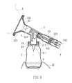
FIG. 1 shows a perspective view of a homecare suction device according to the present invention. -
FIG. 2 shows a cross sectional view of a main body of the homecare suction device according to the present invention. -
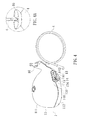
FIG. 3 shows a cross sectional view of a breast pump and a container. -
FIG. 4 shows a perspective view of the main body and a hose. -
FIG. 4A is an enlarged view of a portion of the main body and an end of the hose. -
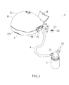
FIG. 5 shows a perspective view of the main body and a nasal mucus sucker. -
FIG. 6 shows a perspective view of the main body and a sprayer with a mask. -
FIG. 7 shows a perspective view of the main body and a sprayer with a mouth biting portion. -
FIG. 8 shows a perspective view of the main body and an injector. - With reference to
FIGS. 1-3 , a homecare suction device A according to the present invention includes amain body 1 having ahousing 11. Anair pump 12 is mounted in thehousing 11. Thehousing 11 includes anair outlet 142 and anair inlet 144. Theair pump 12 is in communication with theair outlet 142 and theair inlet 144. - The homecare suction device A further includes a
container 2 having anopening 21. Thecontainer 2 is adapted to receive aliquid 9. In the preferred embodiment, thecontainer 2 is supported on abase 22. - The homecare suction device A further includes a
breast pump 3 having acover 31 mounted to the opening 21 of thecontainer 2. In the preferred embodiment, thecover 31 and the opening 21 of thecontainer 2 are connected by threading connection. Thecover 31 includes aliquid sucking unit 32 and anair sucking unit 33. Each of theliquid sucking unit 32 and theair sucking unit 33 is in communication with an interior of thecontainer 2. Theliquid sucking unit 32 includes aliquid passage 321 and acup 322. Thecup 322 is adapted to contact with anobject 8. In the preferred embodiment, theliquid sucking unit 32 is trumpet-shaped, and asoft rubber pad 323 is mounted to a surface of thecup 322. Theair sucking unit 33 includes anair passage 331 and aconnection port 332 in communication with theair inlet 144 of themain body 1. In the preferred embodiment, theair sucking unit 33 further includes acontrol switch 333 for controlling a suction force of theair sucking unit 33, which is known in the art. Afunnel 311 is mounted in thecover 31 and in communication with theliquid passage 321, theair passage 331, and the interior of thecontainer 2. In the preferred embodiment, thefunnel 311 tapers downward and is located between thecover 31 and theopening 21 of thecontainer 2. Thefunnel 311 is made of soft rubber. Thecover 31 further includes avent 312 communicating the interior of thecontainer 2 with the outside, preventing generation of an excessive negative pressure in thecontainer 2 to avoid the liquid 9 in thecontainer 2 from being sucked into theair passage 331. - The homecare suction device A further includes a
hose 4 having two ends respectively connected to theair inlet 144 and theconnection port 332. Thus, themain body 1 and thebreast pump 3 can be easily detached from each other, allowing use of themain body 1 with a device requiring suction, injection, or atomization. - In an embodiment shown in
FIG. 5 , theair inlet 144 is connected by thehose 4 to anasal mucus sucker 5. Thenasal mucus sucker 5 includes anasal suction tube 51 and acontrol hole 52. In another embodiment shown inFIG. 6 , theair inlet 144 is connected by thehose 4 to asprayer 6 with amask 61 for medical treatment of a nasal cavity of a patient. In a further embodiment shown inFIG. 7 , theair inlet 144 is connected by thehose 4 to asprayer 6 with a mouth-bitingportion 62 for medical treatment of a throat of a patient. In still another embodiment shown inFIG. 8 , theair inlet 144 is connected by thehose 4 to an injector 7 including aninjection tube 71 and acontrol hole 72. Thus, themain body 1 provides many applications. Use of thenasal mucus sucker 5, thesprayer 6, and the injector 7 are well known in the art and, therefore, not described to avoid redundancy. - Since the
funnel 311 is in communication with theliquid passage 321, theair passage 331, and thecontainer 2, the liquid 9 from thebreast pump 3 can flow through theliquid passage 321 and thefunnel 311 into thecontainer 2 in which theliquid 9 can be stored. Since theair pump 12 continuously draws air to suck theliquid 9, a sucking force is applied to theobject 8 during operation of theair pump 12 because theair passage 331 is also in communication with the interior of thecontainer 2 via thefunnel 311. Namely, the air in thecontainer 2 is sucked out and generates a negative pressure in thecontainer 2. When the negative pressure in thecontainer 2 becomes too large, theliquid 9 in thecontainer 2 will be sucked into theair passage 331 via thefunnel 311, causing damage to theair pump 12. Thevent 312 of thecover 31 communicating the interior of thecontainer 2 with the outside avoids excessive negative pressure in thecontainer 2, avoiding theliquid 9 in thecontainer 2 from entering theair pump 12 via theair passage 331, maintaining normal operation of theair pump 12 and prolonging the service life of theair pump 12. - With reference to
FIG. 2 , thehousing 11 includes anupper housing 111, alower housing 112, and aconnection portion 13 sandwiched between the upper andlower housings connection portion 13 includes aboard 14. Anair outlet tube 141 and a firstair inlet tube 143 extend through theboard 14. Theair outlet tube 141 includes theair outlet 142. The firstair inlet tube 143 includes theair inlet 144. Anannular flange 145 is formed around a top end of the firstair inlet tube 143. Anannular wall 146 is formed around theannular flange 145. An annular groove is defined between theannular flange 145 and theannular wall 146.Filter cotton 147 is mounted in theannular flange 145 and covers the top end of the firstair inlet tube 143. Aseal ring 148 is mounted in the annular groove. Aninlet coupler 15 is mounted in theannular wall 146. Theinlet coupler 15 includes a second air inlet tube 152 and an annularouter wall 151 surrounding the second air inlet tube 152. The second air inlet tube 152 is in communication with the firstair inlet tube 143. - Air is filtered by the
filter cotton 147 before entering theair pump 12, avoiding accumulation of dirt or bacteria and keeping theair inlet tube 121 clean. Since thefilter cotton 147 is mounted to theconnection portion 13, replacement of thefilter cotton 147 can be easily achieved after detaching theinlet coupler 15. - With reference to
FIGS. 2 ,4 , and6-8 , anair cap 153 is provided to avoid a user from attachment with the second air inlet tube 152 or theair outlet tube 141. Theair cap 153 is tightly mounted to the second air inlet tube 152 and located in the annularouter wall 151. Theair cap 153 includes a top face having anair passageway 154. Theair passageway 154 has an inner diameter smaller than an outer diameter of thehose 4. When the user is intended to use theair outlet tube 141, thehose 4 can not be attached to the second air inlet 152, avoiding adverse affect to the normal operation of theair pump 12 and avoiding shortening of the service life of themain body 1. With reference toFIGS. 1 and5 , when it is intended to use the second inlet tube 152, theair cap 153 is removed, and thehose 4 is connected to the second inlet tube 152. - With reference to
FIG. 4A , thehousing 11 includes a fixinghole 16 in an end thereof. Thehose 4 can be fixed in the fixinghole 16 when not in use. - Although specific embodiments have been illustrated and described, numerous modifications and variations are still possible without departing from the scope of the invention. The scope of the invention is limited by the accompanying claims.
Claims (10)
- A homecare suction device comprising:a main body including a housing, with an air pump mounted in the housing, with the housing including an air outlet and an air inlet, with the air pump being in communication with the air outlet and the air inlet;a container including an opening, with the container adapted to receive a liquid;a breast pump including a cover mounted to the opening of the container, with the cover including a liquid sucking unit and an air sucking unit, with each of the liquid sucking unit and the air sucking unit being in communication with an interior of the container, with the liquid sucking unit including a liquid passage and a cup, with the cup adapted to contact with an object, with the air sucking unit including an air passage and a connection port in communication with the air inlet of the main body, with a funnel mounted in the cover and in communication with the liquid passage, the air passage, and the interior of the container, with the cover further including a vent communicating the interior of the container with outside, preventing generation of an excessive negative pressure in the container to avoid the liquid in the container from being sucked into the air passage; anda hose including two ends respectively connected to the air inlet and the connection port.
- The homecare suction device as claimed in claim 1, with the housing including an upper housing, a lower housing, and a connection portion sandwiched between the upper and lower housings, with the connection portion including a board, with an air outlet tube and a first air inlet tube extending through the board, with the air outlet tube including the air outlet, with the first air inlet tube including the air inlet, with an annular flange formed around a top end of the first air inlet tube, with an annular wall formed around the annular flange, with an annular groove defined between the annular flange and the annular wall, with filter cotton mounted in the annular flange and covering the top end of the first air inlet tube, with a seal ring mounted in the annular groove, with an inlet coupler mounted in the annular wall, with the inlet coupler including a second air inlet tube and an annular outer wall surrounding the second air inlet tube, with the second air inlet tube being in communication with the first air inlet tube.
- The homecare suction device as claimed in claim 2, further comprising an air cap tightly mounted to the second air inlet tube and located in the annular outer wall, with the air cap including a top face having an air passageway, with the air passageway having an inner diameter smaller than an outer diameter of the hose.
- The homecare suction device as claimed in claim 2, wherein the funnel is made of soft rubber.
- The homecare suction device as claimed in claim 1, with the liquid sucking unit being trumpet-shaped, with a soft rubber pad mounted to a surface of the cup.
- The homecare suction device as claimed in claim 1, with the air sucking unit further including a control switch, with the control switch controlling a suction force of the air sucking unit.
- The homecare suction device as claimed in claim 1, further comprising a base, with the container supported on the base.
- The homecare suction device as claimed in claim 1, with the housing including a fixing hole in an end thereof, with the hose fixed in the fixing hole.
- The homecare suction device as claimed in claim 1, with the air outlet selectively connected to a sprayer or an injector by the hose.
- The homecare suction device as claimed in claim 1, with the air inlet selectively connected to a nasal mucus sucker by the hose.
Applications Claiming Priority (1)
| Application Number | Priority Date | Filing Date | Title |
|---|---|---|---|
| CN2012207149776U CN203075300U (en) | 2012-12-21 | 2012-12-21 | Home nursing collecting and sucking machine |
Publications (1)
| Publication Number | Publication Date |
|---|---|
| EP2745858A1 true EP2745858A1 (en) | 2014-06-25 |
Family
ID=47900902
Family Applications (1)
| Application Number | Title | Priority Date | Filing Date |
|---|---|---|---|
| EP13159711.4A Withdrawn EP2745858A1 (en) | 2012-12-21 | 2013-03-18 | Homecare suction device |
Country Status (3)
| Country | Link |
|---|---|
| US (1) | US9511176B2 (en) |
| EP (1) | EP2745858A1 (en) |
| CN (1) | CN203075300U (en) |
Families Citing this family (14)
| Publication number | Priority date | Publication date | Assignee | Title |
|---|---|---|---|---|
| WO2015035224A1 (en) * | 2013-09-05 | 2015-03-12 | Maternal Life, Llc | Connector for collection and dispensing of breast milk or colostrum |
| US10426705B2 (en) * | 2013-09-05 | 2019-10-01 | Lansinoh Laboratories, Inc. | Colostrum collection system |
| US10080825B2 (en) * | 2013-09-05 | 2018-09-25 | Lansinoh Laboratories, Inc. | Connector for collection and dispensing of breast milk or colostrum |
| WO2017035769A1 (en) * | 2015-09-01 | 2017-03-09 | 温玉桂 | Household atomisation device |
| CN105597201A (en) * | 2016-02-04 | 2016-05-25 | 深圳金亿帝医疗设备股份有限公司 | Atomizer and atomizer main body |
| USD811579S1 (en) * | 2016-02-10 | 2018-02-27 | Exploramed Nc7, Inc. | Flex conduit for a breast pump |
| SG10202011077XA (en) * | 2016-02-10 | 2020-12-30 | Exploramed Nc7 Inc | A breast pump container assemblies and methods |
| USD862680S1 (en) * | 2016-02-10 | 2019-10-08 | Exploramed Nc7, Inc. | Container assembly for a breast pump |
| US20190191970A1 (en) * | 2017-12-26 | 2019-06-27 | Maurice A. Greene | Handheld vacuum device with camera and illumination |
| JP2022500209A (en) | 2018-09-06 | 2022-01-04 | ランシノー ラボラトリーズ,インコーポレイティド | Vibration waveform for milking machine |
| US10857271B2 (en) | 2018-09-06 | 2020-12-08 | Lansinoh Laboratories, Inc. | Closed loop electric breast pump |
| WO2020051456A1 (en) | 2018-09-06 | 2020-03-12 | Lansinoh Laboratories, Inc. | Breast pumps |
| CN114650801A (en) * | 2019-07-29 | 2022-06-21 | 巴比娅什公司 | Breast pump system |
| CN110917019A (en) * | 2019-11-08 | 2020-03-27 | 深圳市海文生物科技有限公司 | Spray nose washing device |
Citations (10)
| Publication number | Priority date | Publication date | Assignee | Title |
|---|---|---|---|---|
| EP0330845A2 (en) * | 1988-02-29 | 1989-09-06 | I S G Ag | Improved breast pump assembly having motor drive for use with manual piston pump |
| DE9420699U1 (en) * | 1994-12-27 | 1995-03-23 | Illes Csok & Partner Arbeitsge | Nasal mucus and / or breast milk suction apparatus |
| US5590648A (en) * | 1992-11-30 | 1997-01-07 | Tremont Medical | Personal health care system |
| US5830198A (en) * | 1994-10-11 | 1998-11-03 | Stryker Corporation | Blood conservation system |
| WO1999051882A1 (en) * | 1998-04-03 | 1999-10-14 | Medela, Inc. | Diaphragm pump and pump for double-breast pumping |
| WO2000001431A1 (en) * | 1998-07-06 | 2000-01-13 | Evenflo Company, Inc. | Self cycling breast pump |
| DE102004030692B3 (en) * | 2004-06-24 | 2005-12-22 | Kaweco Gmbh | Milchabsaugvorrichtung |
| EP2186532A1 (en) * | 2008-11-12 | 2010-05-19 | Ardo medical AG | Breast pump |
| EP2335750A1 (en) * | 2002-07-19 | 2011-06-22 | Medela Holding AG | Connector device |
| DE102010019041A1 (en) * | 2010-05-03 | 2011-11-03 | Mapa Gmbh | Electric breastmilk pump |
Family Cites Families (10)
| Publication number | Priority date | Publication date | Assignee | Title |
|---|---|---|---|---|
| GB185521A (en) * | 1921-06-10 | 1922-09-11 | Miguel Rodriguez Del Castillo | Pneumatic milk extractor |
| US3084691A (en) * | 1960-11-04 | 1963-04-09 | Air Shields | Aspirator |
| FR2398249B1 (en) * | 1977-07-18 | 1981-11-27 | Boyer Jean Jacques | |
| US5295957A (en) * | 1991-12-23 | 1994-03-22 | Pigeon Co., Ltd. | Breast pump having a pressure adjusting mechanism |
| JP3593434B2 (en) * | 1997-02-06 | 2004-11-24 | サンデン株式会社 | Heat exchanger unit |
| US20030212374A1 (en) * | 2002-05-08 | 2003-11-13 | Timothy Gusler | Nose vacuum |
| US7354418B2 (en) * | 2004-05-06 | 2008-04-08 | L. Jason Clute | Express kits and cup liners for human milking apparatus |
| US20050283900A1 (en) * | 2004-06-23 | 2005-12-29 | Campbell Graham J | Safety suction inlet |
| US7615037B2 (en) * | 2005-12-14 | 2009-11-10 | Stryker Corporation | Removable inlet manifold for a medical/surgical waste collection system, the manifold including a driver for actuating a valve integral with the waste collection system |
| US20110054389A1 (en) * | 2009-08-31 | 2011-03-03 | Christopher Do | Method and apparatus for cleaning a nasal passage |
-
2012
- 2012-12-21 CN CN2012207149776U patent/CN203075300U/en not_active Expired - Lifetime
-
2013
- 2013-03-12 US US13/795,166 patent/US9511176B2/en active Active
- 2013-03-18 EP EP13159711.4A patent/EP2745858A1/en not_active Withdrawn
Patent Citations (10)
| Publication number | Priority date | Publication date | Assignee | Title |
|---|---|---|---|---|
| EP0330845A2 (en) * | 1988-02-29 | 1989-09-06 | I S G Ag | Improved breast pump assembly having motor drive for use with manual piston pump |
| US5590648A (en) * | 1992-11-30 | 1997-01-07 | Tremont Medical | Personal health care system |
| US5830198A (en) * | 1994-10-11 | 1998-11-03 | Stryker Corporation | Blood conservation system |
| DE9420699U1 (en) * | 1994-12-27 | 1995-03-23 | Illes Csok & Partner Arbeitsge | Nasal mucus and / or breast milk suction apparatus |
| WO1999051882A1 (en) * | 1998-04-03 | 1999-10-14 | Medela, Inc. | Diaphragm pump and pump for double-breast pumping |
| WO2000001431A1 (en) * | 1998-07-06 | 2000-01-13 | Evenflo Company, Inc. | Self cycling breast pump |
| EP2335750A1 (en) * | 2002-07-19 | 2011-06-22 | Medela Holding AG | Connector device |
| DE102004030692B3 (en) * | 2004-06-24 | 2005-12-22 | Kaweco Gmbh | Milchabsaugvorrichtung |
| EP2186532A1 (en) * | 2008-11-12 | 2010-05-19 | Ardo medical AG | Breast pump |
| DE102010019041A1 (en) * | 2010-05-03 | 2011-11-03 | Mapa Gmbh | Electric breastmilk pump |
Also Published As
| Publication number | Publication date |
|---|---|
| CN203075300U (en) | 2013-07-24 |
| US20140180205A1 (en) | 2014-06-26 |
| US9511176B2 (en) | 2016-12-06 |
Similar Documents
| Publication | Publication Date | Title |
|---|---|---|
| US9511176B2 (en) | Homecare suction device | |
| US8529501B2 (en) | One time use breastpump assembly | |
| JP5581388B2 (en) | Breast shield for milking human breast milk | |
| JP5554829B2 (en) | Nasal aspirator | |
| JP2013163014A (en) | Medical/nursing-care suction device | |
| TW201634066A (en) | Adapter with media separating diaphragm for a breast shield | |
| US20090105674A1 (en) | Snivel aspirator | |
| CN105848691B (en) | Storage container | |
| CN109481750A (en) | A kind of ear-nose-throat department suction sputum cleaning device | |
| US20160175496A1 (en) | Suction device | |
| KR101342444B1 (en) | Breast milk pump | |
| CN211068278U (en) | Breathe sputum aspirator for internal medicine | |
| CN213311628U (en) | Belt cleaning device is used to otolaryngology branch of academic or vocational study | |
| KR101070932B1 (en) | Pparatus extracting mother's milk | |
| JP6529741B2 (en) | Medical suction machine | |
| CN210433780U (en) | Safe type pediatric internal medicine sputum aspirator | |
| KR20210086320A (en) | Thermo massage breast pump | |
| CN206837173U (en) | Detached type vacuum suction connecting tube | |
| KR101028916B1 (en) | Medical Suction Apparatus | |
| CN213251687U (en) | Novel sputum aspirator and system | |
| CN111840667B (en) | Double-layer nasal aspirator | |
| CN211634510U (en) | Department of respiration nursing is with inhaling phlegm device | |
| CN218652615U (en) | Sputum aspirator | |
| CN211132365U (en) | Medical portable sputum suction cup device | |
| CN218652723U (en) | A subassembly is placed in disinfection for inhaling phlegm connecting pipe |
Legal Events
| Date | Code | Title | Description |
|---|---|---|---|
| PUAI | Public reference made under article 153(3) epc to a published international application that has entered the european phase |
Free format text: ORIGINAL CODE: 0009012 |
|
| 17P | Request for examination filed |
Effective date: 20130418 |
|
| AK | Designated contracting states |
Kind code of ref document: A1 Designated state(s): AL AT BE BG CH CY CZ DE DK EE ES FI FR GB GR HR HU IE IS IT LI LT LU LV MC MK MT NL NO PL PT RO RS SE SI SK SM TR |
|
| AX | Request for extension of the european patent |
Extension state: BA ME |
|
| STAA | Information on the status of an ep patent application or granted ep patent |
Free format text: STATUS: THE APPLICATION IS DEEMED TO BE WITHDRAWN |
|
| 18D | Application deemed to be withdrawn |
Effective date: 20150106 |