EP2740591B1 - Color Shifting Film - Google Patents
Color Shifting Film Download PDFInfo
- Publication number
- EP2740591B1 EP2740591B1 EP13180705.9A EP13180705A EP2740591B1 EP 2740591 B1 EP2740591 B1 EP 2740591B1 EP 13180705 A EP13180705 A EP 13180705A EP 2740591 B1 EP2740591 B1 EP 2740591B1
- Authority
- EP
- European Patent Office
- Prior art keywords
- film
- color
- optical
- films
- layers
- Prior art date
- Legal status (The legal status is an assumption and is not a legal conclusion. Google has not performed a legal analysis and makes no representation as to the accuracy of the status listed.)
- Expired - Lifetime
Links
- 239000000463 material Substances 0.000 claims description 106
- 230000005540 biological transmission Effects 0.000 claims description 96
- 238000001228 spectrum Methods 0.000 claims description 56
- 239000010408 film Substances 0.000 description 344
- 239000010410 layer Substances 0.000 description 280
- 230000003287 optical effect Effects 0.000 description 127
- 238000000034 method Methods 0.000 description 82
- 239000011112 polyethylene naphthalate Substances 0.000 description 58
- 229920003207 poly(ethylene-2,6-naphthalate) Polymers 0.000 description 54
- 238000013461 design Methods 0.000 description 52
- 230000003595 spectral effect Effects 0.000 description 47
- 230000008569 process Effects 0.000 description 46
- 238000005266 casting Methods 0.000 description 44
- 239000004926 polymethyl methacrylate Substances 0.000 description 40
- 229920003229 poly(methyl methacrylate) Polymers 0.000 description 38
- 230000000694 effects Effects 0.000 description 37
- 239000012788 optical film Substances 0.000 description 34
- 238000000411 transmission spectrum Methods 0.000 description 28
- 229920000642 polymer Polymers 0.000 description 27
- 239000003086 colorant Substances 0.000 description 22
- 230000008859 change Effects 0.000 description 20
- 238000002310 reflectometry Methods 0.000 description 19
- 239000010409 thin film Substances 0.000 description 17
- 230000007423 decrease Effects 0.000 description 16
- 238000009826 distribution Methods 0.000 description 15
- 230000001965 increasing effect Effects 0.000 description 14
- 238000004519 manufacturing process Methods 0.000 description 13
- 230000010287 polarization Effects 0.000 description 13
- 238000001125 extrusion Methods 0.000 description 12
- 239000011347 resin Substances 0.000 description 11
- 229920005989 resin Polymers 0.000 description 11
- 230000007704 transition Effects 0.000 description 10
- 230000009467 reduction Effects 0.000 description 9
- 238000005482 strain hardening Methods 0.000 description 9
- 239000011521 glass Substances 0.000 description 8
- 239000000155 melt Substances 0.000 description 8
- 230000002829 reductive effect Effects 0.000 description 8
- 230000008033 biological extinction Effects 0.000 description 7
- 230000003247 decreasing effect Effects 0.000 description 7
- 238000010791 quenching Methods 0.000 description 7
- 239000000976 ink Substances 0.000 description 6
- 229920006254 polymer film Polymers 0.000 description 6
- 238000000985 reflectance spectrum Methods 0.000 description 6
- 230000009897 systematic effect Effects 0.000 description 6
- XLYOFNOQVPJJNP-UHFFFAOYSA-N water Substances O XLYOFNOQVPJJNP-UHFFFAOYSA-N 0.000 description 6
- 230000015556 catabolic process Effects 0.000 description 5
- 238000006731 degradation reaction Methods 0.000 description 5
- 239000011229 interlayer Substances 0.000 description 5
- 238000003754 machining Methods 0.000 description 5
- 239000000203 mixture Substances 0.000 description 5
- 239000000049 pigment Substances 0.000 description 5
- 229920006395 saturated elastomer Polymers 0.000 description 5
- 238000000926 separation method Methods 0.000 description 5
- 230000007480 spreading Effects 0.000 description 5
- 238000003892 spreading Methods 0.000 description 5
- 238000010521 absorption reaction Methods 0.000 description 4
- 238000000576 coating method Methods 0.000 description 4
- 238000007906 compression Methods 0.000 description 4
- 230000006835 compression Effects 0.000 description 4
- WOZVHXUHUFLZGK-UHFFFAOYSA-N dimethyl terephthalate Chemical compound COC(=O)C1=CC=C(C(=O)OC)C=C1 WOZVHXUHUFLZGK-UHFFFAOYSA-N 0.000 description 4
- 239000000975 dye Substances 0.000 description 4
- 230000001747 exhibiting effect Effects 0.000 description 4
- 230000033001 locomotion Effects 0.000 description 4
- 238000010128 melt processing Methods 0.000 description 4
- 230000001681 protective effect Effects 0.000 description 4
- 230000000171 quenching effect Effects 0.000 description 4
- 230000002441 reversible effect Effects 0.000 description 4
- 229920001634 Copolyester Polymers 0.000 description 3
- 238000004364 calculation method Methods 0.000 description 3
- 239000013078 crystal Substances 0.000 description 3
- 239000006185 dispersion Substances 0.000 description 3
- 230000009977 dual effect Effects 0.000 description 3
- 238000004049 embossing Methods 0.000 description 3
- 238000010438 heat treatment Methods 0.000 description 3
- 230000007246 mechanism Effects 0.000 description 3
- 230000000737 periodic effect Effects 0.000 description 3
- 229920006267 polyester film Polymers 0.000 description 3
- 238000012545 processing Methods 0.000 description 3
- 230000003746 surface roughness Effects 0.000 description 3
- 238000001429 visible spectrum Methods 0.000 description 3
- BQCADISMDOOEFD-UHFFFAOYSA-N Silver Chemical compound [Ag] BQCADISMDOOEFD-UHFFFAOYSA-N 0.000 description 2
- GWEVSGVZZGPLCZ-UHFFFAOYSA-N Titan oxide Chemical compound O=[Ti]=O GWEVSGVZZGPLCZ-UHFFFAOYSA-N 0.000 description 2
- 230000001154 acute effect Effects 0.000 description 2
- 239000000654 additive Substances 0.000 description 2
- 230000000996 additive effect Effects 0.000 description 2
- 238000004458 analytical method Methods 0.000 description 2
- 239000005395 beveled glass Substances 0.000 description 2
- 238000006243 chemical reaction Methods 0.000 description 2
- 239000011248 coating agent Substances 0.000 description 2
- 238000010276 construction Methods 0.000 description 2
- 238000001816 cooling Methods 0.000 description 2
- 238000007334 copolymerization reaction Methods 0.000 description 2
- 238000002425 crystallisation Methods 0.000 description 2
- 230000008025 crystallization Effects 0.000 description 2
- 230000002939 deleterious effect Effects 0.000 description 2
- 238000010586 diagram Methods 0.000 description 2
- VNGOYPQMJFJDLV-UHFFFAOYSA-N dimethyl benzene-1,3-dicarboxylate Chemical compound COC(=O)C1=CC=CC(C(=O)OC)=C1 VNGOYPQMJFJDLV-UHFFFAOYSA-N 0.000 description 2
- 238000002474 experimental method Methods 0.000 description 2
- 238000001914 filtration Methods 0.000 description 2
- 238000009499 grossing Methods 0.000 description 2
- 238000005286 illumination Methods 0.000 description 2
- 238000007654 immersion Methods 0.000 description 2
- 230000006872 improvement Effects 0.000 description 2
- 238000005495 investment casting Methods 0.000 description 2
- 238000002955 isolation Methods 0.000 description 2
- 229910052751 metal Inorganic materials 0.000 description 2
- 239000002184 metal Substances 0.000 description 2
- 238000002156 mixing Methods 0.000 description 2
- 229920006255 plastic film Polymers 0.000 description 2
- 239000002985 plastic film Substances 0.000 description 2
- 229920000728 polyester Polymers 0.000 description 2
- 229920005644 polyethylene terephthalate glycol copolymer Polymers 0.000 description 2
- 238000004886 process control Methods 0.000 description 2
- 238000005086 pumping Methods 0.000 description 2
- 229910052709 silver Inorganic materials 0.000 description 2
- 239000004332 silver Substances 0.000 description 2
- 239000012748 slip agent Substances 0.000 description 2
- 239000011734 sodium Substances 0.000 description 2
- 239000000758 substrate Substances 0.000 description 2
- 230000001629 suppression Effects 0.000 description 2
- 238000009736 wetting Methods 0.000 description 2
- 238000004804 winding Methods 0.000 description 2
- PXGZQGDTEZPERC-UHFFFAOYSA-N 1,4-cyclohexanedicarboxylic acid Chemical compound OC(=O)C1CCC(C(O)=O)CC1 PXGZQGDTEZPERC-UHFFFAOYSA-N 0.000 description 1
- OCJBOOLMMGQPQU-UHFFFAOYSA-N 1,4-dichlorobenzene Chemical compound ClC1=CC=C(Cl)C=C1 OCJBOOLMMGQPQU-UHFFFAOYSA-N 0.000 description 1
- MCSXGCZMEPXKIW-UHFFFAOYSA-N 3-hydroxy-4-[(4-methyl-2-nitrophenyl)diazenyl]-N-(3-nitrophenyl)naphthalene-2-carboxamide Chemical compound Cc1ccc(N=Nc2c(O)c(cc3ccccc23)C(=O)Nc2cccc(c2)[N+]([O-])=O)c(c1)[N+]([O-])=O MCSXGCZMEPXKIW-UHFFFAOYSA-N 0.000 description 1
- 229910000968 Chilled casting Inorganic materials 0.000 description 1
- RYGMFSIKBFXOCR-UHFFFAOYSA-N Copper Chemical compound [Cu] RYGMFSIKBFXOCR-UHFFFAOYSA-N 0.000 description 1
- DGAQECJNVWCQMB-PUAWFVPOSA-M Ilexoside XXIX Chemical compound C[C@@H]1CC[C@@]2(CC[C@@]3(C(=CC[C@H]4[C@]3(CC[C@@H]5[C@@]4(CC[C@@H](C5(C)C)OS(=O)(=O)[O-])C)C)[C@@H]2[C@]1(C)O)C)C(=O)O[C@H]6[C@@H]([C@H]([C@@H]([C@H](O6)CO)O)O)O.[Na+] DGAQECJNVWCQMB-PUAWFVPOSA-M 0.000 description 1
- 241000692870 Inachis io Species 0.000 description 1
- 241000145324 Paracheirodon innesi Species 0.000 description 1
- ISWSIDIOOBJBQZ-UHFFFAOYSA-N Phenol Chemical compound OC1=CC=CC=C1 ISWSIDIOOBJBQZ-UHFFFAOYSA-N 0.000 description 1
- -1 Polyethylene naphthalate Polymers 0.000 description 1
- 206010037867 Rash macular Diseases 0.000 description 1
- 229920010524 Syndiotactic polystyrene Polymers 0.000 description 1
- YIMQCDZDWXUDCA-UHFFFAOYSA-N [4-(hydroxymethyl)cyclohexyl]methanol Chemical compound OCC1CCC(CO)CC1 YIMQCDZDWXUDCA-UHFFFAOYSA-N 0.000 description 1
- 238000005299 abrasion Methods 0.000 description 1
- 238000002835 absorbance Methods 0.000 description 1
- 238000000137 annealing Methods 0.000 description 1
- 238000013459 approach Methods 0.000 description 1
- 230000004888 barrier function Effects 0.000 description 1
- 230000008901 benefit Effects 0.000 description 1
- 230000000740 bleeding effect Effects 0.000 description 1
- 230000003749 cleanliness Effects 0.000 description 1
- 230000000295 complement effect Effects 0.000 description 1
- 239000002131 composite material Substances 0.000 description 1
- 230000001010 compromised effect Effects 0.000 description 1
- 239000000470 constituent Substances 0.000 description 1
- 238000011109 contamination Methods 0.000 description 1
- 229910052802 copper Inorganic materials 0.000 description 1
- 239000010949 copper Substances 0.000 description 1
- 239000002537 cosmetic Substances 0.000 description 1
- 230000008878 coupling Effects 0.000 description 1
- 238000010168 coupling process Methods 0.000 description 1
- 238000005859 coupling reaction Methods 0.000 description 1
- 238000004132 cross linking Methods 0.000 description 1
- 238000013016 damping Methods 0.000 description 1
- 230000032798 delamination Effects 0.000 description 1
- 230000001419 dependent effect Effects 0.000 description 1
- 239000002274 desiccant Substances 0.000 description 1
- 238000011161 development Methods 0.000 description 1
- 229940117389 dichlorobenzene Drugs 0.000 description 1
- 150000005690 diesters Chemical class 0.000 description 1
- 238000009792 diffusion process Methods 0.000 description 1
- 230000003292 diminished effect Effects 0.000 description 1
- 150000002009 diols Chemical class 0.000 description 1
- 238000001035 drying Methods 0.000 description 1
- 230000005670 electromagnetic radiation Effects 0.000 description 1
- 238000000572 ellipsometry Methods 0.000 description 1
- 150000002148 esters Chemical class 0.000 description 1
- 210000003746 feather Anatomy 0.000 description 1
- 238000009472 formulation Methods 0.000 description 1
- 230000008014 freezing Effects 0.000 description 1
- 238000007710 freezing Methods 0.000 description 1
- 239000000499 gel Substances 0.000 description 1
- 229910000078 germane Inorganic materials 0.000 description 1
- 230000009477 glass transition Effects 0.000 description 1
- 238000009998 heat setting Methods 0.000 description 1
- 229920001519 homopolymer Polymers 0.000 description 1
- 239000012535 impurity Substances 0.000 description 1
- 230000001939 inductive effect Effects 0.000 description 1
- 229910010272 inorganic material Inorganic materials 0.000 description 1
- 239000011147 inorganic material Substances 0.000 description 1
- 238000009434 installation Methods 0.000 description 1
- 238000012886 linear function Methods 0.000 description 1
- 239000011159 matrix material Substances 0.000 description 1
- 238000002844 melting Methods 0.000 description 1
- 230000008018 melting Effects 0.000 description 1
- 150000002739 metals Chemical class 0.000 description 1
- 230000004048 modification Effects 0.000 description 1
- 238000012986 modification Methods 0.000 description 1
- 239000000178 monomer Substances 0.000 description 1
- 230000006911 nucleation Effects 0.000 description 1
- 238000010899 nucleation Methods 0.000 description 1
- 238000005457 optimization Methods 0.000 description 1
- 230000010355 oscillation Effects 0.000 description 1
- 230000003534 oscillatory effect Effects 0.000 description 1
- 238000000643 oven drying Methods 0.000 description 1
- 239000005022 packaging material Substances 0.000 description 1
- 239000003973 paint Substances 0.000 description 1
- 230000036961 partial effect Effects 0.000 description 1
- 239000002245 particle Substances 0.000 description 1
- 239000011236 particulate material Substances 0.000 description 1
- 238000009304 pastoral farming Methods 0.000 description 1
- 230000000704 physical effect Effects 0.000 description 1
- 229920000515 polycarbonate Polymers 0.000 description 1
- 239000004417 polycarbonate Substances 0.000 description 1
- 239000002952 polymeric resin Substances 0.000 description 1
- 229920000909 polytetrahydrofuran Polymers 0.000 description 1
- 238000004321 preservation Methods 0.000 description 1
- 239000011241 protective layer Substances 0.000 description 1
- 230000004044 response Effects 0.000 description 1
- 238000000518 rheometry Methods 0.000 description 1
- 150000003839 salts Chemical class 0.000 description 1
- 239000004576 sand Substances 0.000 description 1
- 238000002791 soaking Methods 0.000 description 1
- 229910052708 sodium Inorganic materials 0.000 description 1
- 230000003068 static effect Effects 0.000 description 1
- 239000000126 substance Substances 0.000 description 1
- 229920003002 synthetic resin Polymers 0.000 description 1
- 239000004408 titanium dioxide Substances 0.000 description 1
- 238000005809 transesterification reaction Methods 0.000 description 1
- 125000000391 vinyl group Chemical group [H]C([*])=C([H])[H] 0.000 description 1
- 229920002554 vinyl polymer Polymers 0.000 description 1
- 230000000007 visual effect Effects 0.000 description 1
- 238000010792 warming Methods 0.000 description 1
- 239000002023 wood Substances 0.000 description 1
- 238000013316 zoning Methods 0.000 description 1
Images


Classifications
-
- B—PERFORMING OPERATIONS; TRANSPORTING
- B32—LAYERED PRODUCTS
- B32B—LAYERED PRODUCTS, i.e. PRODUCTS BUILT-UP OF STRATA OF FLAT OR NON-FLAT, e.g. CELLULAR OR HONEYCOMB, FORM
- B32B7/00—Layered products characterised by the relation between layers; Layered products characterised by the relative orientation of features between layers, or by the relative values of a measurable parameter between layers, i.e. products comprising layers having different physical, chemical or physicochemical properties; Layered products characterised by the interconnection of layers
- B32B7/02—Physical, chemical or physicochemical properties
- B32B7/023—Optical properties
-
- B—PERFORMING OPERATIONS; TRANSPORTING
- B29—WORKING OF PLASTICS; WORKING OF SUBSTANCES IN A PLASTIC STATE IN GENERAL
- B29C—SHAPING OR JOINING OF PLASTICS; SHAPING OF MATERIAL IN A PLASTIC STATE, NOT OTHERWISE PROVIDED FOR; AFTER-TREATMENT OF THE SHAPED PRODUCTS, e.g. REPAIRING
- B29C48/00—Extrusion moulding, i.e. expressing the moulding material through a die or nozzle which imparts the desired form; Apparatus therefor
- B29C48/03—Extrusion moulding, i.e. expressing the moulding material through a die or nozzle which imparts the desired form; Apparatus therefor characterised by the shape of the extruded material at extrusion
- B29C48/07—Flat, e.g. panels
- B29C48/08—Flat, e.g. panels flexible, e.g. films
-
- B—PERFORMING OPERATIONS; TRANSPORTING
- B32—LAYERED PRODUCTS
- B32B—LAYERED PRODUCTS, i.e. PRODUCTS BUILT-UP OF STRATA OF FLAT OR NON-FLAT, e.g. CELLULAR OR HONEYCOMB, FORM
- B32B27/00—Layered products comprising a layer of synthetic resin
- B32B27/06—Layered products comprising a layer of synthetic resin as the main or only constituent of a layer, which is next to another layer of the same or of a different material
- B32B27/08—Layered products comprising a layer of synthetic resin as the main or only constituent of a layer, which is next to another layer of the same or of a different material of synthetic resin
-
- B—PERFORMING OPERATIONS; TRANSPORTING
- B32—LAYERED PRODUCTS
- B32B—LAYERED PRODUCTS, i.e. PRODUCTS BUILT-UP OF STRATA OF FLAT OR NON-FLAT, e.g. CELLULAR OR HONEYCOMB, FORM
- B32B7/00—Layered products characterised by the relation between layers; Layered products characterised by the relative orientation of features between layers, or by the relative values of a measurable parameter between layers, i.e. products comprising layers having different physical, chemical or physicochemical properties; Layered products characterised by the interconnection of layers
- B32B7/04—Interconnection of layers
- B32B7/12—Interconnection of layers using interposed adhesives or interposed materials with bonding properties
-
- B—PERFORMING OPERATIONS; TRANSPORTING
- B44—DECORATIVE ARTS
- B44F—SPECIAL DESIGNS OR PICTURES
- B44F1/00—Designs or pictures characterised by special or unusual light effects
- B44F1/08—Designs or pictures characterised by special or unusual light effects characterised by colour effects
- B44F1/14—Iridescent effects
-
- G—PHYSICS
- G02—OPTICS
- G02B—OPTICAL ELEMENTS, SYSTEMS OR APPARATUS
- G02B5/00—Optical elements other than lenses
- G02B5/08—Mirrors
- G02B5/0816—Multilayer mirrors, i.e. having two or more reflecting layers
- G02B5/0825—Multilayer mirrors, i.e. having two or more reflecting layers the reflecting layers comprising dielectric materials only
- G02B5/0841—Multilayer mirrors, i.e. having two or more reflecting layers the reflecting layers comprising dielectric materials only comprising organic materials, e.g. polymers
-
- G—PHYSICS
- G02—OPTICS
- G02B—OPTICAL ELEMENTS, SYSTEMS OR APPARATUS
- G02B5/00—Optical elements other than lenses
- G02B5/20—Filters
- G02B5/28—Interference filters
- G02B5/281—Interference filters designed for the infrared light
-
- G—PHYSICS
- G02—OPTICS
- G02B—OPTICAL ELEMENTS, SYSTEMS OR APPARATUS
- G02B5/00—Optical elements other than lenses
- G02B5/20—Filters
- G02B5/28—Interference filters
- G02B5/285—Interference filters comprising deposited thin solid films
- G02B5/287—Interference filters comprising deposited thin solid films comprising at least one layer of organic material
-
- G—PHYSICS
- G02—OPTICS
- G02B—OPTICAL ELEMENTS, SYSTEMS OR APPARATUS
- G02B5/00—Optical elements other than lenses
- G02B5/30—Polarising elements
- G02B5/3025—Polarisers, i.e. arrangements capable of producing a definite output polarisation state from an unpolarised input state
- G02B5/3033—Polarisers, i.e. arrangements capable of producing a definite output polarisation state from an unpolarised input state in the form of a thin sheet or foil, e.g. Polaroid
- G02B5/3041—Polarisers, i.e. arrangements capable of producing a definite output polarisation state from an unpolarised input state in the form of a thin sheet or foil, e.g. Polaroid comprising multiple thin layers, e.g. multilayer stacks
- G02B5/305—Polarisers, i.e. arrangements capable of producing a definite output polarisation state from an unpolarised input state in the form of a thin sheet or foil, e.g. Polaroid comprising multiple thin layers, e.g. multilayer stacks including organic materials, e.g. polymeric layers
-
- B—PERFORMING OPERATIONS; TRANSPORTING
- B29—WORKING OF PLASTICS; WORKING OF SUBSTANCES IN A PLASTIC STATE IN GENERAL
- B29C—SHAPING OR JOINING OF PLASTICS; SHAPING OF MATERIAL IN A PLASTIC STATE, NOT OTHERWISE PROVIDED FOR; AFTER-TREATMENT OF THE SHAPED PRODUCTS, e.g. REPAIRING
- B29C48/00—Extrusion moulding, i.e. expressing the moulding material through a die or nozzle which imparts the desired form; Apparatus therefor
- B29C48/25—Component parts, details or accessories; Auxiliary operations
- B29C48/88—Thermal treatment of the stream of extruded material, e.g. cooling
- B29C48/911—Cooling
- B29C48/9135—Cooling of flat articles, e.g. using specially adapted supporting means
- B29C48/914—Cooling of flat articles, e.g. using specially adapted supporting means cooling drums
-
- B—PERFORMING OPERATIONS; TRANSPORTING
- B29—WORKING OF PLASTICS; WORKING OF SUBSTANCES IN A PLASTIC STATE IN GENERAL
- B29C—SHAPING OR JOINING OF PLASTICS; SHAPING OF MATERIAL IN A PLASTIC STATE, NOT OTHERWISE PROVIDED FOR; AFTER-TREATMENT OF THE SHAPED PRODUCTS, e.g. REPAIRING
- B29C48/00—Extrusion moulding, i.e. expressing the moulding material through a die or nozzle which imparts the desired form; Apparatus therefor
- B29C48/25—Component parts, details or accessories; Auxiliary operations
- B29C48/88—Thermal treatment of the stream of extruded material, e.g. cooling
- B29C48/911—Cooling
- B29C48/9135—Cooling of flat articles, e.g. using specially adapted supporting means
- B29C48/915—Cooling of flat articles, e.g. using specially adapted supporting means with means for improving the adhesion to the supporting means
- B29C48/9165—Electrostatic pinning
-
- B—PERFORMING OPERATIONS; TRANSPORTING
- B32—LAYERED PRODUCTS
- B32B—LAYERED PRODUCTS, i.e. PRODUCTS BUILT-UP OF STRATA OF FLAT OR NON-FLAT, e.g. CELLULAR OR HONEYCOMB, FORM
- B32B2307/00—Properties of the layers or laminate
- B32B2307/40—Properties of the layers or laminate having particular optical properties
- B32B2307/416—Reflective
-
- Y—GENERAL TAGGING OF NEW TECHNOLOGICAL DEVELOPMENTS; GENERAL TAGGING OF CROSS-SECTIONAL TECHNOLOGIES SPANNING OVER SEVERAL SECTIONS OF THE IPC; TECHNICAL SUBJECTS COVERED BY FORMER USPC CROSS-REFERENCE ART COLLECTIONS [XRACs] AND DIGESTS
- Y10—TECHNICAL SUBJECTS COVERED BY FORMER USPC
- Y10S—TECHNICAL SUBJECTS COVERED BY FORMER USPC CROSS-REFERENCE ART COLLECTIONS [XRACs] AND DIGESTS
- Y10S428/00—Stock material or miscellaneous articles
- Y10S428/916—Fraud or tamper detecting
-
- Y—GENERAL TAGGING OF NEW TECHNOLOGICAL DEVELOPMENTS; GENERAL TAGGING OF CROSS-SECTIONAL TECHNOLOGIES SPANNING OVER SEVERAL SECTIONS OF THE IPC; TECHNICAL SUBJECTS COVERED BY FORMER USPC CROSS-REFERENCE ART COLLECTIONS [XRACs] AND DIGESTS
- Y10—TECHNICAL SUBJECTS COVERED BY FORMER USPC
- Y10T—TECHNICAL SUBJECTS COVERED BY FORMER US CLASSIFICATION
- Y10T428/00—Stock material or miscellaneous articles
- Y10T428/12—All metal or with adjacent metals
- Y10T428/12229—Intermediate article [e.g., blank, etc.]
- Y10T428/12236—Panel having nonrectangular perimeter
- Y10T428/1225—Symmetrical
-
- Y—GENERAL TAGGING OF NEW TECHNOLOGICAL DEVELOPMENTS; GENERAL TAGGING OF CROSS-SECTIONAL TECHNOLOGIES SPANNING OVER SEVERAL SECTIONS OF THE IPC; TECHNICAL SUBJECTS COVERED BY FORMER USPC CROSS-REFERENCE ART COLLECTIONS [XRACs] AND DIGESTS
- Y10—TECHNICAL SUBJECTS COVERED BY FORMER USPC
- Y10T—TECHNICAL SUBJECTS COVERED BY FORMER US CLASSIFICATION
- Y10T428/00—Stock material or miscellaneous articles
- Y10T428/12—All metal or with adjacent metals
- Y10T428/12229—Intermediate article [e.g., blank, etc.]
- Y10T428/12271—Intermediate article [e.g., blank, etc.] having discrete fastener, marginal fastening, taper, or end structure
- Y10T428/12278—Same structure at both ends of plural taper
-
- Y—GENERAL TAGGING OF NEW TECHNOLOGICAL DEVELOPMENTS; GENERAL TAGGING OF CROSS-SECTIONAL TECHNOLOGIES SPANNING OVER SEVERAL SECTIONS OF THE IPC; TECHNICAL SUBJECTS COVERED BY FORMER USPC CROSS-REFERENCE ART COLLECTIONS [XRACs] AND DIGESTS
- Y10—TECHNICAL SUBJECTS COVERED BY FORMER USPC
- Y10T—TECHNICAL SUBJECTS COVERED BY FORMER US CLASSIFICATION
- Y10T428/00—Stock material or miscellaneous articles
- Y10T428/12—All metal or with adjacent metals
- Y10T428/12306—Workpiece of parallel, nonfastened components [e.g., fagot, pile, etc.]
- Y10T428/12313—Arranged to avoid lateral displacement
-
- Y—GENERAL TAGGING OF NEW TECHNOLOGICAL DEVELOPMENTS; GENERAL TAGGING OF CROSS-SECTIONAL TECHNOLOGIES SPANNING OVER SEVERAL SECTIONS OF THE IPC; TECHNICAL SUBJECTS COVERED BY FORMER USPC CROSS-REFERENCE ART COLLECTIONS [XRACs] AND DIGESTS
- Y10—TECHNICAL SUBJECTS COVERED BY FORMER USPC
- Y10T—TECHNICAL SUBJECTS COVERED BY FORMER US CLASSIFICATION
- Y10T428/00—Stock material or miscellaneous articles
- Y10T428/24—Structurally defined web or sheet [e.g., overall dimension, etc.]
- Y10T428/24802—Discontinuous or differential coating, impregnation or bond [e.g., artwork, printing, retouched photograph, etc.]
- Y10T428/24851—Intermediate layer is discontinuous or differential
- Y10T428/24868—Translucent outer layer
-
- Y—GENERAL TAGGING OF NEW TECHNOLOGICAL DEVELOPMENTS; GENERAL TAGGING OF CROSS-SECTIONAL TECHNOLOGIES SPANNING OVER SEVERAL SECTIONS OF THE IPC; TECHNICAL SUBJECTS COVERED BY FORMER USPC CROSS-REFERENCE ART COLLECTIONS [XRACs] AND DIGESTS
- Y10—TECHNICAL SUBJECTS COVERED BY FORMER USPC
- Y10T—TECHNICAL SUBJECTS COVERED BY FORMER US CLASSIFICATION
- Y10T428/00—Stock material or miscellaneous articles
- Y10T428/24—Structurally defined web or sheet [e.g., overall dimension, etc.]
- Y10T428/24942—Structurally defined web or sheet [e.g., overall dimension, etc.] including components having same physical characteristic in differing degree
-
- Y—GENERAL TAGGING OF NEW TECHNOLOGICAL DEVELOPMENTS; GENERAL TAGGING OF CROSS-SECTIONAL TECHNOLOGIES SPANNING OVER SEVERAL SECTIONS OF THE IPC; TECHNICAL SUBJECTS COVERED BY FORMER USPC CROSS-REFERENCE ART COLLECTIONS [XRACs] AND DIGESTS
- Y10—TECHNICAL SUBJECTS COVERED BY FORMER USPC
- Y10T—TECHNICAL SUBJECTS COVERED BY FORMER US CLASSIFICATION
- Y10T428/00—Stock material or miscellaneous articles
- Y10T428/25—Web or sheet containing structurally defined element or component and including a second component containing structurally defined particles
-
- Y—GENERAL TAGGING OF NEW TECHNOLOGICAL DEVELOPMENTS; GENERAL TAGGING OF CROSS-SECTIONAL TECHNOLOGIES SPANNING OVER SEVERAL SECTIONS OF THE IPC; TECHNICAL SUBJECTS COVERED BY FORMER USPC CROSS-REFERENCE ART COLLECTIONS [XRACs] AND DIGESTS
- Y10—TECHNICAL SUBJECTS COVERED BY FORMER USPC
- Y10T—TECHNICAL SUBJECTS COVERED BY FORMER US CLASSIFICATION
- Y10T428/00—Stock material or miscellaneous articles
- Y10T428/28—Web or sheet containing structurally defined element or component and having an adhesive outermost layer
- Y10T428/2848—Three or more layers
-
- Y—GENERAL TAGGING OF NEW TECHNOLOGICAL DEVELOPMENTS; GENERAL TAGGING OF CROSS-SECTIONAL TECHNOLOGIES SPANNING OVER SEVERAL SECTIONS OF THE IPC; TECHNICAL SUBJECTS COVERED BY FORMER USPC CROSS-REFERENCE ART COLLECTIONS [XRACs] AND DIGESTS
- Y10—TECHNICAL SUBJECTS COVERED BY FORMER USPC
- Y10T—TECHNICAL SUBJECTS COVERED BY FORMER US CLASSIFICATION
- Y10T428/00—Stock material or miscellaneous articles
- Y10T428/29—Coated or structually defined flake, particle, cell, strand, strand portion, rod, filament, macroscopic fiber or mass thereof
-
- Y—GENERAL TAGGING OF NEW TECHNOLOGICAL DEVELOPMENTS; GENERAL TAGGING OF CROSS-SECTIONAL TECHNOLOGIES SPANNING OVER SEVERAL SECTIONS OF THE IPC; TECHNICAL SUBJECTS COVERED BY FORMER USPC CROSS-REFERENCE ART COLLECTIONS [XRACs] AND DIGESTS
- Y10—TECHNICAL SUBJECTS COVERED BY FORMER USPC
- Y10T—TECHNICAL SUBJECTS COVERED BY FORMER US CLASSIFICATION
- Y10T428/00—Stock material or miscellaneous articles
- Y10T428/31504—Composite [nonstructural laminate]
- Y10T428/31786—Of polyester [e.g., alkyd, etc.]
Definitions
- the present invention relates generally to optical films, and more specifically to optical films that change color as a function of viewing angle.
- the present invention pertains to optical films that are useful in colored displays. Such displays are frequently used as a means to display information in an eye-catching manner, or to draw attention to a specific article on display or for sale. These displays are often used in signage (e.g., outdoor billboards and street signs), in kiosks, and on a wide variety of packaging materials.
- signage e.g., outdoor billboards and street signs
- a display can be made to change color as a function of viewing angle.
- Such displays known as “color shifting displays”, are noticeable even when viewed peripherally, and serve to direct the viewer's attention to the object on display.
- inks which are printed onto card stock or onto a transparent or translucent substrate.
- inks are typically not color shifting (i.e., the colors of such inks do not normally change as a function of viewing angle).
- Some color shifting inks have also been developed, chiefly for use in security applications. However, in addition to their considerable expense, some inks of this type are opaque and are therefore not suitable for backlit applications. Furthermore, such inks are typically based on multilayer stacks of isotropic materials, and hence lose color saturation as viewing angle increases.
- Color shifting pigments are also known.
- a family of light interference pigments are commercially available from Flex Products, Inc. under the trade designation CHROMAFLAIR, and these pigments have been used to make decals.
- the product literature accompanying these decals describes them as consisting of color shifting pigments in a commercial paint formulation, which is then applied to a vinyl substrate.
- the color shifting effect provided by these materials is only observable at fairly large oblique angles, and is limited to a shift between two colors.
- these materials which are apparently described in U.S. Patent No. 5,084,351 (Phillips et al. ), U.S. Patent No. 5,569,535 (Phillips et al. ), and U.S. Patent No.
- An iridescent plastic film is currently sold under the trade designation BLACK MAGIC by the Engelhard Corporation.
- the film has been advertised in Cosmetics & Personal Care Magazine (Sept.-Oct. 1997) as a black tinted, translucent film 0.7 mil thick but containing more than 100 layers which provides an effect similar to that seen with neon tetra fish, peacock feathers and oil films.
- the plastic film is a multilayer stack of optically thin films. Thickness variations in the films results in color variations across the area of the film. Although the deviations of the thickness caliper from its average value are not large, they are significant in terms of the color differences in adjacent areas.
- the various versions of the film are not labeled as a single reflectance color, but instead as dual colored films. For example, the film is commercially available in blue/green and red/green color combinations, among others.
- Multilayer films made from extruded polymeric materials have been found to be highly susceptible to distortions in layer thickness and optical caliper, which result in color variations and impurities across the width of the film. This problem was commented on in Optical Document Security, 251-252 (Ed. R. van Renesse, 1994 ). In describing the multilayer polymeric films produced to date by Dow Chemical Company and their licensee, Mearl Corporation, the reference notes that control of thickness variations of the individual layers in these films is very difficult and that, as a result, the films exhibit "countless narrow streaks of varying color, few of which are wider than 2-3 mm.” Id, At 251.
- the present invention pertains to multilayer birefringent color shifting films and other optical bodies having particular relationships between the refractive indices of successive layers for light polarized along mutually orthogonal in-plane axes (the x-axis and the y-axis) and along an axis perpendicular to the in-plane axes (the z-axis).
- the differences in refractive indices along the x-, y-, and z-axes are such that the absolute value of ⁇ z is less than about one half the larger of the absolute value of ⁇ x and the absolute value of ⁇ y (e.g., (
- ⁇ 0.5k, k max ⁇
- Films having this property can be made to exhibit transmission spectra in which the widths and intensities of the transmission or reflection peaks (when plotted as a function of frequency, or 1/ ⁇ ) for p-polarized light remain substantially constant over a wide range of viewing angles.
- the spectral features shift toward the blue region of the spectrum at a higher rate with angle change than the spectral features of isotropic thin film stacks.
- the present invention pertains to color shifting films having at least one reflection band.
- the numeric signs of the layer birefringences, the z-index mismatch, and the stack f-ratio either the short or long wavelength bandedges of the reflection bands for s- and p-polarized light are substantially coincident at all angles of incidence.
- Films of this type when designed using the bandedge sharpening techniques described herein, exhibit the maximum color purity possible with a thin film stack designed for use over large angle and wavelength ranges. In addition to sharp color transitions and high color purity, such films are advantageous in applications requiring non-polarizing color beamsplitters.
- the present invention pertains to a multilayer color shifting film made from strain hardening materials which exhibits a high degree of color uniformity at a given angle of incidence, and to a method for making the same, wherein at least some of the primary reflection bands in the film arise from an optical stack within the film having optically thin layers (i.e., layers whose optical thickness is within the range 0.01 to 0.45 micrometers).
- the layers within the optical stack have a high degree of physical and optical caliper uniformity.
- the distortions in layer thickness and optical caliper encountered in prior art non-strain hardening films is avoided by biaxially stretching the cast web by a factor of 2x2 to 6x6, and preferably, about 4x4, which tends to make the lateral layer thickness variations, and therefore the color variations, much less abrupt.
- a narrower die can be used in making stretched film compared to making cast film of the same width, and this allows for the possibility of fewer distortions of the layer thickness distribution in the extrusion die because of the significantly less melt flow spreading occurring in the narrower die. Additional control over layer thickness and optical caliper is achieved through the use of a precision casting wheel drive mechanism having a constant rotation speed.
- the casting wheel is designed and operated such that it is free of vibrations that would otherwise cause web thickness chatter and subsequent layer thickness variations in the down-web direction. It has been found that, absent these controls, the normal vibrations encountered in the extrusion process are sufficient to noticeably affect color uniformity, due in part to the low tensile strength in the molten state of the strain hardening materials that are employed in making the optical films of the present invention.
- the method of the invention has allowed the production, for the first time, of color shifting films made from polymeric materials which have a high degree of color uniformity at a particular viewing angle (e.g., films in which the wavelength values of the bandedges of the spectral bands of light which are transmitted or reflected at a particular angle of incidence vary by less than about 2% over an area of at least 10 cm 2 .
- the films resulting from the method exhibit essentially uniform layer thickness and optical caliper within the optical stack, thereby resulting in color shifts that are sharper and more rapid as a function of viewing angle as compared to films having a lower degree of physical and optical caliper uniformity.
- the present invention pertains to color shifting films that are made with strain hardening materials (e.g., strain hardening polyesters).
- strain hardening materials e.g., strain hardening polyesters.
- the reflectivity, or extinction, of a reflectance band increases as a function of both the number of layers tuned to that wavelength band and the index differential of the layer pairs.
- strain hardening materials which exhibit high indices of refraction after stretching, creates large index differentials when paired with selected low index polymers.
- the required number of layers decreases in direct proportion with an increase in the index differential.
- the layer thickness uniformity can be improved as the number of layers is decreased, since a lower number of layers lessens the dependence on layer multipliers and large feedblock sizes to produce the required number of layers As a result, polymeric film stacks can be made with more precise control of layer thickness for improved spectral characteristics.
- the present invention relates to color shifting films that behave as-polarizers over one or more regions of the spectrum. Such films exhibit color shifts when viewed in transmission, or when viewed in reflection after being laminated to (or coated with) a white, diffusely reflective background such as cardstock.
- the color shifting polarizers may also be combined with other polarizers or mirrors to produce a variety of interesting optical effects.
- the color shifting films of the present invention may be used advantageously as low absorbence materials in displays, providing bright display colors with high luminous efficiency.
- the display colors may be readily derived by coupling a source of broadband light to the optical film in such a way that various colors of the source light can be viewed in either transmission or reflection.
- the film may also be combined with a broadband mirror.
- a broadband mirror such that the film and the mirror are approximately parallel but are separated by a small distance, an article is obtained which exhibits 3-D "depth”.
- the film may be formed into several different geometries and combined with different light sources to advantageously utilize the high spectral reflectivity and angular selectivity of the film.
- the color shifting films of the present invention are optically anisotropic multilayer polymer films that change color as a function of viewing angle. These films, which may be designed to reflect one or both polarizations of light over at least one bandwidth, can be tailored to exhibit a sharp bandedge at one or both sides of at least one reflective bandwidth, thereby giving a high degree of color saturation at acute angles.
- the layer thicknesses and indices of refraction of the optical stacks within the color shifting films of the present invention are controlled to reflect at least one polarization of specific wavelengths of light (at a particular angle of incidence) while being transparent over other wavelengths.
- the films of the present invention may be made to behave as mirrors or polarizers over one or more regions of the spectrum.
- the films of the present invention may be tuned to reflect both polarizations of light in the IR region of the spectrum while being transparent over other portions of the spectrum, thereby making them ideal for use in low-E type fenestrations.
- the films of the present invention have two features that make them ideal for certain types of color displays.
- the shape e.g., the bandwidth and reflectivity values
- the optical transmission/reflection spectrum of the multilayer film for p-polarized light can be made to remain essentially unchanged over a wide range of angles of incidence.
- a broadband mirror film having a narrow transmission band at, for example, 650 nm will appear deep red in transmission at normal incidence, then red, yellow, green, and blue at successively higher angles of incidence.
- Such behavior is analogous to moving a color dispersed beam of light across a slit in a spectrophotometer.
- the films of the present invention may be used to make a simple spectrophotometer.
- the color shift with angle is typically greater than that of conventional isotropic multilayer films.
- the color shifting films of the present invention may be designed with a wide variety of reflective spectral features to produce varying optical effects.
- bandedge sharpening may be used to render a more dramatic change in color with angle, or this feature may be combined with light sources that have one or more narrow emission bands.
- softer color changes may be achieved by increasing the bandedge slope, or by the use of films that do not reflect light of a given polarization state equally along orthogonal film planes. This is the case, for example, with asymmetrically biaxially stretched films, which have weaker reflectivity for light with the E-field along the minor stretch axis than for light with the E-field along the major stretch axis. In such films, the color purity of both transmitted and reflected light will be lessened.
- the material layer with high in-plane indices has a thickness axis (z-axis) index that is equal to the z-axis index of the low index material, and if index dispersion is neglected, then the shape of the transmission spectrum will not change with angle for p-polarized light when plotted in frequency space, i.e., when plotted as a function of reciprocal wavelength.
- This effect derives from the functional form of the Fresnel reflection coefficient for p-polarized light incident at the interface between uniaxially birefringent materials, and the functional form of the f-ratio for a quarterwave stack of birefringent films.
- the optical axes x, y, and z are assumed to be mutually orthogonal, with x and y being in the plane of the film stack and z being orthogonal to the film plane.
- x and y are typically the orthogonal stretch directions of the film, and the z axis is normal to the plane of the film.
- the Fresnel coefficients for sand p-polarized light are given by EQUATIONS B1-1 and B1-2.
- EQUATIONS B1-1 and B1-2 also are valid along the orthogonal stretch and nonstretch axes of uniaxially stretched films used to make biaxially birefringent reflective polarizers.
- EQUATION B1-1 is also valid along the in-plane optical axes of films in which these axes are not orthogonal, or are not coincident with the stretch directions of the film. Performance at azimuthal angles between such axes require more extensive mathematical descriptions, but the required mathematical modeling techniques are known in the art.
- a particularly useful optical stack is one in which the two z-indices of refraction are equal, or nearly equal, compared to the in-plane index differential.
- the above equations for the Fresnel reflection coefficient are independent of layer thicknesses, and predict only interfacial effects.
- the magnitude of the achievable reflectance and bandwidth of a multilayer thin film stack depends greatly on the thickness of all the layers as the optical thickness of the layers determines the phasing required for constructive interference.
- a two component quarterwave stack is used, having equal optical thickness for each layer in the half wave unit cell.
- An f-ratio of 0.5 offers maximum bandwidth and reflectivity for a thin film optical stack. If the stack is designed to have an f-ratio of 0.5 at normal incidence, the f-ratio will increase at oblique angles for isotropic materials assuming the first material has the higher index.
- the f-ratio can increase, decrease, or remain constant as a function of angle of incidence, depending on the relationship of the z-indices to the in-plane indices of the two material components.
- each material can be calculated by multiplying its physical thickness by the effective phase index given by EQUATIONS B1-5 and B 1-6.
- multilayer interference filters made with alternating layers of materials which satisfy the matched z-index relationship exhibit spectral features such as reflectivity and fractional bandwidth for p-polarized light which are independent of angle of incidence.
- the constant spectral shape as a function of angle for p-polarized light is an important effect at work in many of the color shifting displays described herein, and can be utilized to produce colored multilayer interference films having high color purity at all angles of incidence.
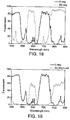
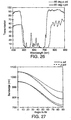
- An example of a multilayer film exhibiting a constant reflectance spectrum for p-polarized light is shown in FIG. 18 .
- a film was made in accordance with EXAMPLE E1-2, but with about a 30% slower casting wheel speed.
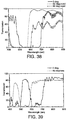
- the transmission spectrum at normal incidence and at 60° for p-polarized light is shown in FIG. 18 .
- the transmission spectrum at normal incidence and at 60° for s-polarized light is shown in FIG. 19 .
- the stop band near 600 nm at normal incidence has a bandwidth of 103 nm (543 to 646 nm) and an average transmission of 5.5% within that stopband.
- the blue bandedge has a slope of 0.66% per nm, while the red edge has a slope of 2.1 % per nm.
- the passband at 700 nm at normal incidence has a bandwidth of 100 nm and a maximum transmission of 85%.
- the slopes of the passband bandedges are: 2.3 percent per nm on the blue side, and 1.9 percent per nm on the red side.
- the shape of the entire spectral curve is substantially the same at a 60° angle of incidence as compared to normal incidence.
- the spectra of FIG. 18 and FIG. 19 were obtained with light polarized parallel to the TD (crossweb direction).
- the indices of refraction of the quarter wave thick PET layers cannot be measured directly, it is thought that they will be approximately the same as the indices of the PET skin layers.
- the latter indices were measured for this example using a Metricon Prism coupler manufactured by Metricon Corporation of Pennington, NJ.
- the indices were measured for the crossweb (tentered or TD) direction, the downweb (Machine or MD) direction, also referred to as the Length Oriented or LO direction, and thickness or z axis direction.
- the isotropic index of the Ecdel is about 1.52.
- the average of the spectra for s- and p-polarized light will be observed in typical ambient lighting conditions.
- the differing behavior of s- and p-polarized light can be advantageously utilized in various applications.
- the f-ratios of the optical films and devices of the present invention can be manipulated to produce band pass color filters or multiple reflectance bands tuned to particular regions of the spectrum using the extrusion equipment designed only to produce a graded stack of unit cells having a single reflectance band.
- the F-ratios can be controlled to produce a narrow pass green filter with a highly saturated transmission color, while using only a simple thickness graded stack of layers.
- Quarter-wave unit cells suppress the 2 nd order reflection harmonics, while maximizing the intrinsic bandwidth (reflection potential) of the 1 st harmonic.
- a unit cell design which has a relatively high intrinsic bandwidth for both the 1 st and 2 nd order harmonic reflection bands can be obtained by changing the F-ratio to a particular range of values, well away from the QxQ design point.
- the adjacent 1 st and 2 nd order reflectance bandedges will form a passband filter. If the layer pair thickness is adjusted so that the short wavelength bandedge of the 1 st order band is about 600 nm, a pass band in the middle of the visible spectrum will result, as shown in FIG. 20 .
- the PMMA has an isotropic index of about 1.50. Beginning with the thinnest layer pair, each successive layer pair in the stack was designed to be 0.46% thicker than the previous pair. If a larger gradient is used, such as 0.63%, the red bandedge of the 1 st order band is extended further into the IR, the red bandedge of the 2 nd order peak will also increase, resulting in a narrower pass band near 550 nm, as illustrated in FIG. 21 .
- bandedge sharpening techniques can be used to sharpen the edges of the pass band (linear profiles were used in these calculation examples). Suitable bandedge sharpening techniques are described in U.S. Serial No. 09-006,085 entitled "Optical Film with Sharpened Bandedge".
- the cross web uniformity for such a film design will be significantly better than for a two-packet multiplier design such as in example E1-2, as no cross-web multiplier errors will be present. See EXAMPLE B7-1 for comparison to E1-2 as an example of the crossweb variation in multiplier performance.
- FIG. 1 shows a cross-sectional view of a film structure which is not to scale but which is helpful in describing such desirable profiles.
- multilayer film 120 comprises 12 individual layers arranged in an alternating sequence of two optical materials: "A" and "B" material. Three or more distinct optical materials can be used in other embodiments.
- Each pair of adjacent "A” and “B” layers make up an ORU, beginning at the top of the film with ORU1 and ending with ORU6, with the ORUs having optical thicknesses OT 1 , OT 2 , ... OT 6 .
- These optical thicknesses are the same as the term "D r " identified in equation I above.
- each of the ORUs should have a 50% f-ratio with respect to either the A or B layer.
- the A layers can be considered to have a higher X- (in-plane) refractive index than the B layers, since the former are shown thinner than the latter.
- ORUs 1-3 are shown grouped into a multilayer stack S1 in which the optical thickness of the ORUs decrease monotonically in the minus-Z direction.
- ORUs 4-6 are shown grouped into another multilayer stack S2 in which the optical thickness of the ORUs increase monotonically. This ORU optical thickness profile is depicted in FIG. 2 . Thickness profiles such as this are helpful in producing sharpened spectral transitions. Before proceeding with examples of such preferred profiles, however, an example of a bandpass filter without band edge sharpening will be described.
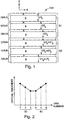
- FIG. 3 illustrates the design of a bandpass multilayer film made up of 300 individual layers. The physical thickness of each individual layer in the film is shown, beginning at the top or front of the film and proceeding toward the bottom or back of the film.
- Data points 122 represent a material having an in-plane refractive index of 1.5 (e.g., PMMA) and points 124 represent a material having an in-plane refractive index of 1.75 (e.g. PEN).
- Layer numbers 1 and 2 constitute the "first" ORU, layers 3 and 4 constitute the second ORU, and so on.
- the optical thickness of a given ORU equals the sum of the optical thickness of the high and low index layer.
- Layers 1 to 150 constitute a first multilayer stack S3 and layers 151 to 300 constitute a second multilayer stack S4. Both such component stacks have a monotonically decreasing ORU optical thicknesses.
- the discontinuity in optical thickness between the two stacks gives rise to a simple notch transmission band 126, shown in FIG. 4.
- FIG. 4 was calculated from the multilayer film of FIG. 1 using the 4x4 matrix methods of Berreman as outlined in Azzam & Bashara, Ellipsometry And Polarized Light , assuming normally incident light and constant refractive index as a function of wavelength (no dispersion).
- Band 126 has a peak transmission of about 60%, a full width at half maximum 128 of about 50 nm, and a center wavelength as shown by line 130 of about 565 nm. The fractional bandwidth of band 126 is slightly below 10%. Reflectance is at least 80% over about 75% of the visible spectrum.
- a film having a much smaller fractional bandwidth can be made by providing additional layers (ORUs) having a particular optical thickness profile which have the effect of sharpening the spectral cut-on and cut-off transitions.
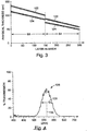
- FIG. 5 illustrates the design of such a film.
- Data points 122,124 stand for the same materials as in FIG. 3 , having refractive indices 1.5 and 1.75 respectively, and the series of 150 layers in multilayer stacks S3 and S4 have the same graded linear thickness distribution as in FIG. 3 .
- the film of FIG. 5 simply adds stacks S5, S6 having substantially constant (non-graded) optical thickness ORUs between stacks S3,S4.
- the ORUs of stack S5 have an optical thickness substantially equal to the minimum optical thickness of stack S3, and the ORUs of stack S6 have an optical thickness substantially equal to the maximum optical thickness of stack S4.
- the same relationship also applies to each constituent of the ORUs.
- the calculated on-axis spectrum for the illustrated stack is given in FIG. 6 , showing a much sharper transmission band 132.
- the percent bandwidth of band 132 is on the order of 3% or less.
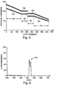
- Another multilayer film whose design is shown in FIG. 7 , was created to improve peak transmission and to make even steeper band edges (narrower transmission band). This was achieved with the same materials used for data points 122,124, by arranging the individual layers into component multilayer stacks S7-S10 as shown, where the stacks S8 and S9 have oppositely curved thickness profiles and the adjacent portions of stacks S7 and S10 have a slightly curved profile to match the curvature of stacks S8 and S9, respectively.
- the curved profile can follow any number of functional forms; the main purpose of the form is to break the exact repetition of thickness present in a quarter wave stack with layers tuned to only single wavelength.
- the particular a function used here is an additive function of a linear profile (the same as used on the short wavelength side of S7 and the long wavelength side of S10) and a sinusoidal function to curve the profile with an appropriate negative or positive first derivative.
- the second derivative of the ORU thickness profile be positive for the red (long wavelength) band edge of a reflectance stack and negative for the blue (short wavelength) band edge of a reflectance stack. Note that the opposite sense is required if one refers to the band edges of the notched transmission band.
- Other embodiments of the same principle include layer profiles that have multiple points with a zero value of the first derivative. In all cases here, the derivatives refer to those of a best fit curve fitted through the actual ORU optical thickness profile, which can contain small statistical errors of less than 10% sigma one standard deviation in optical thickness values.
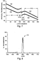
- FIG. 8 shows the calculated on-axis transmission of the film of FIG. 7 .
- Peak transmission of the band 134 is above 75%, and fractional bandwidth is on the order of 2% or less.
- Off-axis transmission spectra, for both p- and s- polarizations were also calculated and are shown as curves 136, 138 respectively in FIG. 9 .
- the calculation was done for an entrance angle of 60 degrees and assumed that the out-of-plane refractive indices of the two types of layers were matched, at an index of 1.5. Note the preservation of the high peak transmission and the small fractional bandwidth for p-polarization. Note also that the transmission peak for s-polarization has disappeared.
- broader transmission bands which were disposed in the near infrared region on-axis are now visible for both s- and p-polarization in the red end of the spectrum in FIG. 9 .
- transition-sharpening techniques can be used for multilayer films having broader transmission features, such as high- or low-pass filters.
- the physical thickness of each layer constituting an ORU is varied at the same pace across the thickness of the film, for example according to the same linear function, while in others the thickness of the layers constituting an ORU are varied differently.
- the high and low index layers have an index of 1.75 and 1.5, respectively, and are dispersionless.
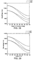
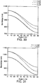
- the component multilayer stack S11 serves as a baseline film design.
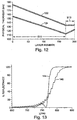
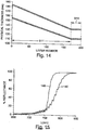
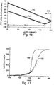
- An on-axis reflectance spectrum 140 was calculated for stack S11 alone, and then for the film combinations: S11+S12 (see FIG. 10 for physical thickness profile and FIG. 11 for reflectance curve 142); S11+S13 (see FIG. 12 for physical thickness profile and FIG. 13 for reflectance curve 144); S11+S14 (see FIG. 14 for physical thickness profile and FIG. 15 for reflectance curve 146); and S11+S15 (see FIG. 16 for physical thickness profile and FIG. 17 for reflectance curve 148).
- stack S11 of a stack with a reverse thickness gradient stack S 12
- a stack with a reverse thickness gradient with f-ratio deviation stack S13
- a stack with a substantially zero thickness gradient stack S14
- a stack with a reverse thickness gradient using only one component of the ORUs stack S15
- higher harmonics can be utilized to produce multiple reflection bands in the visible region of the spectrum without the need for two or more groups of layers.
- Various harmonic suppression designs can be used to create various spectral spacings and colors.
- the second order has maxima.
- the first and fourth orders have equal peak heights, as do the second and third orders.
- the first and fourth orders have equal peak heights, as do the second and third orders.
- the preferred f-ratio will depend on the application and the selected higher order peaks which one desires to suppress or enhance.
- the intrinsic reflection bandwidth for a QxQ stack of a given material layer pair is approximately equal to the Fresnel reflection coefficient of their interface, which at normal incidence depends only on the in-plane index differential.
- Materials selection can also be utilized to produce films and other optical bodies which exhibit a decrease in reflectivity as a function of angle.
- certain combinations of isotropic and birefringent layers can be used in which the spectral contribution of the isotropic layers decreases oblique angle.
- stack designs can also be used to produce a film or other optical body which exhibits color shifts in reflectance with respect to angle of incidence other than those created by the usual monotonic shift of a given spectrum towards shorter wavelengths.
- a 3-material combination can be used to suppress higher order harmonics of p-polarized light at one angle but not at other angles.
- a similar effect for s-polarized light can be achieved with a two-layer design.
- a large or small F-ratio can be used to limit the intrinsic bandwidth. Additional layers are then required to obtain the same reflectivity achievable with a QxQ stack. (A QxQ stack by definition has an f-ratio of 0.5.)
- a QxQ stack by definition has an f-ratio of 0.5.
- a large or small f-ratio can be used and the reflective envelop can be filled out by using a large number of layers (e.g., a thousand or more) with the appropriate thickness gradient and/or materials which exhibit large refractive index mismatches. Alternatively a smaller in-plane refractive index difference to limit the intrinsic bandwidth, and the number of layers increased to compensate for the intensity loss.
- a UV-reflective film can be made which has little or no reflection in the visible region of the spectrum at any angle, but which maintains a broad reflection band in the UV region close to 400 nm across a wide range of angles.
- This is achieved by arranging the layers into two film stacks or packets, a UV and an IR reflecting stack with the UV packet being first order in the UV, and the IR packet designed so it exhibits a higher order reflection peak in the UV region of the spectrum that exhibit a maximum in reflectivity at oblique angles.
- the angle of incidence is varied from normality, and the first order UV peak shifts to shorter wavelengths, the unsuppressed higher order peak from the IR packet moves into the UV.
- the films and optical devices of the present invention may incorporate one or more dyes such that the reflectance band of the film coincides with the absorbance band of the dye for at least one angle of incidence. Since the absorption band(s) of the dye, unlike the reflect bands of the film, will not typically shift with angle of incidence, the film will then exhibit one color at the angle for which the bands coincide, but one or more different colors at other angles after the bands separate. Conversely, the absorption bands could be made to coincide with certain transmission bands in the optical stack at a given angle of incidence. In this way, the film could be made black for example at normal incidence, but at oblique angles, the pass band will move to shorter wavelengths where it will not be covered by the dye spectrum, and the film will become colored. Copper pthalocyanine pigment has rather sharp spectral features in the visible and is particularly suited for this embodiment.
- the films and optical devices of the present invention may be combined with one or more beveled glass prisms.
- a beveled glass prism strip is combined with a film to allow viewing of the colored mirror film at angles other than the spectral angle.
- a microprism material available from 3M Company, St. Paul, MN, under the trade designation such as Optical Lighting Film can be placed adjacent or optically coupled to the multilayer film. The layered film transmits different colors at different angles, and since prisms redirect light, the two can be combined so that one can see a color at a given angle that would normally not be seen had the prism not redirected it toward the viewer.
- the prism can change the angle which light is transmitted into the film, thus altering the color at that point.
- the film exhibits a 3-dimensional effect in which the colored mirror is visible at non-spectral angles. It also produced a variation in color between areas with and without the prisms.
- a film or optical body having a spiky spectral distribution is used as a first element in combination with a second element comprising a broadband colored mirror film.
- the first element has the effect of converting a broadband light source used to illuminate the film to a spiky light source, thereby producing more vivid colors in the colored mirror film. Color changes made by illuminating interference films with spiky light sources have been found to produce color changes which are extraordinarily angularly sensitive.
- iridescent color cancellation may be used to impart a decorative effect to the resulting device.
- two films made in accordance with the present invention may be positioned such that the films are parallel at some points but not at others, or else a colored mirror film made in accordance with the invention may be combined with a broadband mirror film. If the films have complimentary colors, or if one of the films is a broadband mirror film and the other is a colored mirror film, the resulting combination will alter or neutralize the color of the top film in some places, but not in others.
- Certain optical stack designs can be used to produce color shifts with angle of incidence differing from those created by the usual monotonic shift of a given spectrum with angle towards shorter wavelengths.
- the multilayer stacks of the present invention can be combined with multilayer stacks of the prior art to create some unusual angularity effects.
- a birefringent colored film of the present invention having one or more transmission peaks centered at given wavelengths at normal incidence, could be coated, coextruded, or laminated with a stack of isotropic layers which reflect at those given wavelengths at normal incidence. The combined article will then appear as a silvered mirror at normal incidence.
- the isotropic films will leak p-polarized light, allowing the transmission peaks of the birefringent film to be visible, changing to a colored mirror at high angles of incidence.
- This assumes that the reflectance bandwidth of the birefringent stack extends far enough into the IR to block all red light at oblique angles.
- the greatest effect will appear for isotropic film stacks which have a Brewster angle at or near an oblique viewing angle.
- the birefringent stack could also be designed to transmit red at oblique angles if desired.
- a variation of the above design technique includes a birefringent stack with more than one spectral passband in which not all of the passbands are blocked by isotropic reflectance stacks.
- the article will not be silver colored at normal incidence, and will change from one color to another from normal to oblique angles.
- the materials can be selected so that some layers have a z-index mismatch, wherein the z-index of the material having the higher in-plane indices of refraction is the lowest.
- One such combination is PEN/PETG.
- PETG if stretched at temperatures above 120° Celsius has an isotropic index of about 1.57.
- PEN if stretched as described in example E1-1, has nx ⁇ 1.75, ny ⁇ 1.75, and nz ⁇ 1.50.
- These layers will exhibit increased reflectivity at oblique angles for both polarizations so that, if used alone or in combination with z-index matched layers, the resulting film can be designed to appear colored at normal incidence and silver at oblique angles.
- copolyesters and polycarbonates with indices above 1.55 are suitable materials to use in combination with PEN to achieve this effect. While the above examples deal with making a composite film which is colorless for at least one angle of view, these same design techniques can be used to make unusual color shifts (desirable for decorative, security, etc.) which are not colorless at practically any angle of view.
- Certain of the films made in accordance with the present invention can be made to exhibit a blue shift (i.e., a shift of spectral peaks toward the blue end of the spectrum as angle of incidence is varied) that is noticeably larger than that observed with conventional color shifting films. Furthermore, since, for a given (non-normal) angle of incidence, the magnitude of the blue shift will be larger than that observed with conventional films for p-polarized light, the differential of the color shift with respect to the angle of incidence will be greater for the films of the present invention than for conventional films. This latter feature has the effect of making the color shifts in the films of the present invention more noticeable, which in turn makes them more suitable for color shifting displays.
- L the wavelength tuned to the given layer
- ⁇ the angle of incidence measured from normality in that layer
- n the effective index of refraction for the material layer for the given direction and polarization of the light traveling through the layer
- d is the physical thickness of the layer.
- n and Cos ⁇ decrease for p-polarized light as 9 increases.
- the unit cell includes one or more layers of a uniaxially negative birefringent material or biaxially birefringent layers composed of, for example, PEN or PET, wherein the p-polarized light senses a z-index value instead of only the higher in-plane values of the index, the result is a decreasing effective index of refraction for higher angles of incidence.
- the effective low z-index caused by the presence of negatively birefringent layers in the unit cell creates a secondary blue shift in addition to the blue shift present in an isotropic thin stack.
- the compounded effects result in a greater blue shift of the spectrum compared to film stacks composed entirely of isotropic materials.
- the magnitude of the blue shift will be determined by the thickness weighted average change in L with angle of incidence for all material layers in the unit cell.
- the blue shift can be enhanced or lessened by adjusting the relative thickness of the birefringent layer(s) to the isotropic layer(s) in the unit cell. This will result in f-ratio changes that must first be considered in the product design.
- the maximum blue shift in mirrors is attained by using negatively uniaxially birefringent materials in all layers of the stack.
- the extinction bands for p-polarized light move to the blue at a slightly lower rate with angular change than do the same bands for s-polarized light.
- the minimum blue shift is attained by using only uniaxially positive birefringent materials in the optical stack.
- biaxially birefringent materials are used, but for the simple case of light incident along one of the major axes of a birefringent thin film polarizer, the analysis is the same for both uniaxial and biaxial birefringent films.
- the effect is still observable but the analysis is more complex.
- the blue shift of the transmission spectrum for light incident at azimuthal angles between the major axes will have a value intermediate that for light incident along either of the optic axes of the film.
- the optics axes are either aligned with or orthogonal to the stretch axes of the film.
- the in-plane/z-axis index differential of the PEN layers is about 0.25 (1.75 - 1.50). This index differential is less for PET-based films (i.e., about 1.66 - 1.50).
- the effect is even more pronounced because the difference in the PEN in-plane index compared to the PEN z-axis index can be much greater (i.e., about 1.85 - 1.50), resulting in an even greater blue shift for p-polarized light than that observed in biaxially stretched multilayer film stacks.
- the z-index differential of the two materials must be substantially smaller than the in-plane index differentials if high reflectivity is desired for p-polarized light at all angles of incidence.
- An example would be a uniaxially positive birefringent material such as biaxially oriented syndiotactic polystyrene which has a z-index of about 1.63 and in-plane indices of about 1.57.
- the other material could be an isotropic coPEN with an index of about 1.63.
- the birefringent color shifting films of the present invention exhibit improved color saturation, especially as compared to prior art isotropic multilayer films.
- Multilayer color shifting films with isotropic refractive indices suffer from a degradation in their color purity (in either transmission or reflection) as viewing angle through the films is increased from normal-angle to oblique angles (e.g., grazing angles). This is due in part to the fact that the fraction of randomly polarized light that is p-polarized is less efficiently reflected as the propagation angle through the film is increased. Accordingly, the reflection band, while shifting to shorter wavelengths at off-normal angles, also becomes weaker, allowing unwanted spectral components to contaminate the overall transmission spectrum. The problem is especially serious when the films are immersed in glass via cemented prisms or other media with indices substantially higher than 1.0.
- the multilayer birefringent color shifting films of the present invention can maintain their color saturation with increasing viewing angle so long as the refractive indices of the optical layers are appropriately matched along the z-axis (the axis normal to the plane of the film).
- a calculational example of the way color and color saturation changes with increasing viewing angle, for both an isotropic multilayer film and a birefringent multilayer film, is shown below.
- Color purity will increase as the bandwidth narrows toward that of a spike.
- the color purity of the reflected light from a polymeric multilayer stack may be reduced by the broadband reflection from the air/polymer skin layer interface. In this case it may be desirable to provide the polymer film with an anti-reflection coating.
- the index of refraction and the absorption coefficient change.
- the principles of index match and mismatch still apply at each wavelength of interest, and may be utilized in the selection of materials for an optical device that will operate over a specific region of the spectrum.
- proper scaling of dimensions will allow operation in the infrared, near-ultraviolet, and ultra-violet regions of the spectrum.
- the indices of refraction refer to the values at these wavelengths of operation, and the optical thicknesses of the optical layers should also be approximately scaled with wavelength.
- Even more of the electromagnetic spectrum can be used, including very high, ultrahigh, microwave and millimeter wave frequencies.
- Polarizing effects will be present with proper scaling to wavelength and the indices of refraction can be obtained from the square root of the dielectric function (including real and imaginary parts).
- Useful products in these longer wavelength bands can be specularly reflective polarizers and partial polarizers.
- a reflectance band is defined in general as a spectral band of reflection bounded on either side by wavelength regions of low reflection. With dielectric stacks, the absorption is typically low enough to be ignored for many applications, and the definition is given in terms of transmission. In those terms, a reflectance band, or stop band is defined in general as a region of low transmission bounded on both sides by regions of high transmission.
- a single reflectance band or stop band for p-polarized light has a continuous spectrum between any two successive wavelengths at which the transmission is greater than 50 percent, and including such successive wavelengths as endpoints, and where the average transmission from one endpoint to the other is less than 20 percent.
- Such preferred reflectance band or stop band is described in the same way for unpolarized light and light of normal incidence.
- the transmission values in the preceding description are calculated in a way that excludes the portion of light reflected by an air interface with the stack or the stack's skin layers or coatings.
- the bandwidth is defined to be the distance, in nm, between the two wavelengths within the band which are nearest each 50 percent transmission point, at which the transmission is 10 percent. In commonly used terms, the bandwidths are defined by the 10 percent transmission points.
- the respective blue and red (i.e., short and long wavelength) bandedges are then taken to be the wavelength at the above defined 10% transmission points.
- the transmission of the preferred stop band is taken to be the average transmission between the 10 percent transmission points.
- the slope of a bandedge of a stop band as described in the preceding paragraph is taken from the 50 percent and 10 percent transmission/wavelength points, and is given in units of % transmission per nm. If a reflectance band does not have high enough reflectivity to satisfy the definitions of bandwidth and bandedge slopes of the preferred embodiment, then the bandwidth is taken to mean the Full Width at Half Maximum reflectivity.
- a pass band is defined in general as a spectral transmitting band bounded by spectral regions of relatively low transmission. With the multilayer color shifting film, the passband is bounded by reflective stopbands. The width of the pass band is the Full Width at Half Maximum (FWHM) value. Bandedge slopes are calculated from the two points on a given bandedge nearest the peak transmission point, the transmission values of which are 50 and 10 percent of the peak transmission value.
- FWHM Full Width at Half Maximum
- the passband has a transmission band having low transmission regions on both sides of the transmission peak with transmission minima of 10 percent or less of the transmission value of the peak transmission point.
- a pass band having a 50 percent transmission maximum would be bounded on both sides by reflectance bands having 5 percent or lower transmission minima. More preferably, the transmission minima on both sides of the passband are less than 5 percent of the peak transmission value of the passband.
- the bandedge slopes for a pass band be greater than about 0.5 percent transmission per nm. More preferably, the bandedge slopes are greater than about 1 percent per nm, and even more preferably, the slopes are greater than about 2 percent per nm.
- the bandwidth and reflectivity of the birefringent thin film stacks described herein both increase with angle of incidence in the same manner as for conventional isotropic materials.
- the same effects can be produced for p-polarized light if materials of the proper indices are chosen.
- the spectra for s- and p-polarized light can be made to behave similarly or even identically as a function of the angle of incidence.
- U.S. Patent No. 5,808,798 See U.S. Patent No. 5,808,798 .
- the multilayer films described therein have a relatively large z-index mismatch, of the opposite sign as the in-plane index mismatch.
- the phenomenon therein is independent of filter bandwidth and reflectivity.
- birefringent multilayer stacks which have a relatively small z-index mismatch can function as non polarizing color filters in certain special cases.
- bandedges short or long wavelength edge
- Certain color filters such as, e.g., blue or cyan transmitting filters, can have their red bandedges sufficiently far into the IR portions of the spectrum that the polarizing effects there are of no consequence to the intended application.
- bandedges of a thin film stack having an approximate z-index match at the interfaces of two or more materials could be made nonpolarizing to a degree superior to that of an isotropic thin film stack.
- Two examples are given below of birefringent stacks which display an essentially nonpolarizing effect at their blue bandedges, and have simple layer thickness profiles.
- Such thin film stacks would provide a significant improvement over the art for nonpolarizing color beamsplitters, an example of which is given by L. Songer, Photonics Spectra, November 1994, page 88 .
- the five layer ABCBA optical repeating unit stacks of Songer were designed to work at 37.5 degrees in BK-7 glass, which has an index of about 1.52.
- the transmission spectra for s and p-polarized light of a 417 layer coextruded PET/Ecdel film are shown in FIG. 26 . Both spectra were taken at 60 degrees angle of incidence in air, which is equivalent to about 35 degrees in glass having an index of 1.52 such as e.g., BK-7 glass.
- This multilayer film was made as described in EXAMPLE E1-2. As described in that example, the process used to make this multilayer sample utilized an asymmetric two times layer multiplier which doubles the number of layers produced in the feedblock. The multiplier was designed so that the two sets of layers are tuned to reflect separate wavelength bands, centered at wavelengths separated by the multiplier ratio. However, the multipliers do not produce the exact same multiplication ratio at all points across the meltstream.
- the transmission values below 500 nm and above 700nm for the s-polarization are determined primarily by the polymer/air interfaces of the film, and can be improved with anti-reflection coatings, or by immersion in a high index medium such as cementing between glass prisms.
- the average transmission of the stopband for p-polarized light (500 nm to 710 nm) is about 6 percent.
- the slopes of the all the bandedges in this example are about 2.5 percent per nm.
- the reflection band of EXAMPLE B7-1 for p-polarized light has several significant spectral leaks, the average transmission from 500 nm to 710 nm being 6 percent, this example is presented only to illustrate the nonpolarizing bandedges of this optical stack.
- One skilled in the art could easily produce a wide reflectance band filter composed of PET and Ecdel which transmits an average of less than 5 percent or even less than 2percent across over the bandwidth of the stop band.
- the spectra for FIG. 26 were obtained with light polarized parallel to the TD direction, which is also referred to as the x direction in this example.
- the low index material is Ecdel and the index of Ecdel is about 1.52.
- EXAMPLE E1-1 is a multilayer stack of PEN and PMMA.
- the bandedges of the transmission spectra for s and p-polarized light are essentially coincident near 410 nm, while the red bandedges near 600 nm are separated by almost 40 nm.
- the z-index of the PEN in this example is fairly well matched to that of the PMMA, both being about 1.49 at 700 nm.
- PEN has a higher dispersion than PMMA, and near 400 nm nzPEN ⁇ 1.53 while nPMMA ⁇ 1.51.
- the average transmission within the stop band for p-polarized light is 1.23 percent.
- the red bandedge slope is about 4.2 percent per nm and the blue bandedge slope is about 2.2 percent per nm.
- the slope of the red bandedge at normal incidence is about 5.5 percent per nm.
- the optical stack must also provide for high reflectance so that only several percent or less of the p-polarized light of the undesired wavelengths is transmitted. This is necessary as the s-polarization will be more highly reflected than the p-polarization since the Fresnel reflection coefficients will be greatly different at high angles of incidence for the two polarizations.
- the average transmission of p-polarized light within the reflectance band of a nonpolarizing color filter, at the nominal design angle is less than 10 percent, more preferably less than 5 percent, and even more preferably, less than 2 percent.
- the bandedges exhibit a high slope.
- Sharp bandedges also are desirable in obtaining saturated colors of high purity.
- the slopes are at least about 1 percent per nm, more preferably greater than about 2 percent per nm, and even more preferably greater than about 4 percent per nm.
- a computer optimized layer thickness distribution may be utilized, or a band sharpening thickness profile may be applied to the layer thickness distribution design.
- the coincidence of the blue bandedges in the two examples given above is due to a combination of differing bandwidths for s and p-polarized light, and the different rate of spectral shift with angle of the spectra for those polarizations.
- the fractional bandwidth increases for s-polarized light as the incidence angle is increased from zero.
- the fractional bandwidth for p-polarized light does not change with angle because matching the z-indices produces an angle independent Fresnel reflection coefficient for each interface, but the entire band moves slightly faster to the blue, as described above, than does the same band for s-polarized light.
- the two effects nearly cancel on the blue side of the band, with the result that the blue bandedges for both s and p-polarized light remaining nearly coincident at all angles of incidence.
- the two effects add on the red side, with the bandedges for s- and p-polarized light becoming separated.
- the resulting red bandedge becomes an average of the two plots, resulting in slightly lower color purity on the red side in this case for unpolarized light.
- the extinction bands for p-polarized light move to the blue at a slightly lower rate with angular change than do the same bands for s-polanzed light.
- Such an film stack can be used to maintain a sharp bandedge on the red side of an extinction band for unpolarized light, such as, for example, non polarizing yellow and red transmitting filters. Alignment of the blue or red bandedges for s and p-polarized light can be fined tuned by adjustments to the f-ratio of the material layers, or by adjusting the z-index mismatch.
- the f-ratio of a thin film stack can be adjusted to aid in aligning the s and p-polarization bandedges of a reflectance band of the present invention.
- the bandedge positions can be calculated as a function of the angle of incidence.
- the hi and low bandedges are at 953 nm and 1052 nm at normal incidence.
- the p-pol bandedges shift more than the s-pol ones, particularly for the hi bandedge.
- the p-pol band narrows from 99 nm to 73 nm while the s-pol band widens to 124 nm.
- the chart shows a decreasing width for the p-pol reflection band, but if the bandedge values were plotted in terms of reciprocal wavelength, the bandwidth of p-pol band would remain constant. Also note that, while the bandedges on the low wavelength side do not exactly match for the s and p-polarizations, at 60 degrees in air, the difference is only about 10 nm, which is sufficient for many nonpolarizing color filter applications. The p-pol bandedge does shift further to the blue than the corresponding bandedge for the s-polarization which contrasts greatly with the behavior of isotropic quarter wave stacks.
- the p-pol band narrows from 99 nm to 29 nm while the s-pol band widens to 124 nm.
- the center of the isotropic band is the same for s-pol and p-pol, while for anisotropic material, the center of the p-pol band decreases more than the center of the s-pol band.
- the separation of the s-pol and p-pol bandedges at 60° in air is greater than 30 nm. As the index differential of the isotropic materials is increased, the separation of the s and p-pol bandedges also increases. Separations of 50 nm are typical. See, for example, L. Songer, Photonics Spectra, November 1994, page 88 .
- the relative shift of the p-pol bandedges compared to the shift of the s-pol bandedges is substantially affected by the amount of birefringent materials in the stack as well as their absolute birefringence values. For example, increasing the f-ratio of a PEN/PMMA stack will increase the relative amount of material having an in-plane index of 1.75, and will promote a small blue shift in the s-pol reflection band.
- Pushing the f-ratio in the opposite direction for a stack of the same materials will bring the blue bandedge of the p-pol spectrum into alignment with the s-pol spectrum.
- the two are nearly coincident.
- the low wavelength bandedge shifts the same for s-pol and p-pol.
- the p-pol band narrows from 70 nm to 52 nm while the s-pol band widens to 91 nm.
- a large reduction in the f-ratio to provide a match in the s and p-pol bandedges has the drawback of lowering the overall reflective power of the stack, as illustrated in FIG. 22 .
- Another way to provide a match of the s and p blue bandedges at all angles of incidence is to introduce a mismatch in the z-indices. If PET with an in-plane index of 1.66 and a z-index of 1.50 is assumed in an alternating stack with a second material having an isotropic index of 1.45, we see from Fig. 31 that the s and p low wavelength bandedges are substantially coincident at all angles of incidence.
- the coincidence of the blue bandedges for the s- and p-polarization spectra is an important feature of the color shifting films disclosed herein, and has a utility beyond that of a nonpolarizing color filter.
- the coincidence of the s and p bandedges allows the fabrication of color shifting films having an abrupt change of color with viewing angle, and also the fabrication of certain color filters having a high degree of color purity.
- the separation of bandedges for the s- and p-polarizations is preferably less than about 30 about degrees, and more preferably less than about 20 nm. Even more preferably, the separation is less than about 10 nm.
- nonpolarizing color filters described above are useful as color beamsplitters in applications requiring equal bandwidth and reflectivity for s and p-polarizations of colored light.
- such films may find application as the color filters in a three prism color separator of the type described by Doany in U.S. Patent No. 5,644,432 for LCD projection systems.
- a particularly preferred configuration for these films in that type of color separator is to have the light sequentially strike a red reflecting film (cyan transmitter) first, then a film which reflects both green and red (blue transmitter). The blue light traverses both films and strikes the blue LCD light modulator.
- the preferred angle of incidence in the glass prisms described by Doany was 30 degrees, and this angle is easily accomodated by the present invention.
- Typical angles of incidence in glass for a variety of applications are 30 degrees, 35 degrees, 37.5 degrees, and 45 degrees. These angles refer to the center ray of a cone of light.
- the half cone angle may be 5, 10, 15, or even 20 degrees, depending on the f number of the optical system.
- a beamsplitter positioned for a 35 degrees angle of incidence would encounter a range of angles from 20 degrees to 50 degrees angle of incidence on the thin film stack.
- the process used for making the coextruded polymeric multilayer optical films of the present invention will vary depending on the resin materials selected and the optical properties desired in the finished film product.
- Moisture sensitive resins should be dried before or during extrusion to prevent degradation. This can be done by any means known in the art.
- One well-known means employs ovens or more sophisticated heated vacuum and/or desiccant hopper-dryers to dry resin prior to its being fed to an extruder.
- Another means employs a vacuum-vented twinscrew extruder to remove moisture from the resin while it is being extruded. Drying time and temperature should be limited to prevent thermal degradation or sticking during hopper-dryer or oven drying.
- resins coextruded with moisture sensitive resins should be dried to prevent damage to the moisture sensitive coextruded resin from moisture carried by the other resin.
- Extrusion conditions are chosen to adequately feed, melt, mix and pump the polymer resin feed streams in a continuous and stable manner.
- Final melt stream temperatures are chosen within a range which avoids freezing, crystallization or unduly high pressure drops at the low end of the temperature range and which avoids degradation at the high end of the temperature range.
- polyethylene naphthalate (PEN) is dried for 8 hours at 135°C and then vacuum fed to an extruder with a final zone temperature, or melt temperature, ranging preferably between 270°C and 300°C and more preferably between 275°C and 290°C.
- the PEN processing temperature may be reduced so as to match it to the typical melt processing temperatures for PMMA.
- the melting point, and hence, the processing temperature, of PEN may be reduced by the addition of comonomers into the PEN polymer with only a very slight accompanying reduction of the ability of the PEN to develop birefringence upon drawing.
- a PEN copolymer made using DiMethyl Isophthalate (DM1) in place of 3 mol% of the 2,6-DiMethyl Naphthalate (DMN) monomer has been found to have a reduction in birefringence of only 0.02 units, and a reduction of glass transition temperature of only about 4 or 5° C while the melt processing temperature is reduced by 15°C.
- Small amounts of DiMethyl Terephthalate (DMT) or other diacid or diol comonomers may also be useful in this regard. Esters or diesters of the diacid comonomers may also be used.
- melt streams are then filtered to remove undesirable particles and gels.
- Primary and secondary filters known in the art of polyester film manufacture may be used, with mesh sizes in the 1-30 micrometer range. While the prior art indicates the importance of such filtration to film cleanliness and surface properties, its significance in the present invention extends to layer uniformity as well.
- Each melt stream is then conveyed through a neck tube into a gear pump used to regulate the continuous and uniform rate of polymer flow.
- a static mixing unit may be placed at the end of the neck tube carrying the melt from the gear pump into the multilayer feedblock, in order to ensure uniform melt stream temperature. The entire melt stream is heated as uniformly as possible to ensure both uniform flow and minimal degradation during melt processing.
- Multilayer feedblocks are designed to divide two or more polymer melt streams into many layers each, interleave these layers, and merge the many layers of two or more polymers into a single multilayer stream.
- the layers from any given melt stream are created by sequentially bleeding off part of the stream from a main flow channel into side channel tubes that feed layer slots for the individual layers in the feed block manifold.
- Many designs are possible, including those disclosed in U.S. Patent Nos. 3,737,882 ; 3,884,606 ; and 3,687,589 to Schrenk et al. Methods have also been described to introduce a layer thickness gradient by controlling layer flow as described in U.S. Patent Nos.
- layer flow is generally controlled by choices made in machining the shape and physical dimensions of the individual side channel tubes and layer slots.
- the side channel tubes and layer slots of the two or more melt streams are interleaved as desired to form alternating layers.
- the feed block's downstream-side manifold for the combined multilayer stack is shaped to compress and uniformly spread the layers transversely.
- Special thick layers known as protective boundary layers (PBLs) may be fed nearest to the manifold walls from any of the melt streams used for the optical multilayer stack, or by a separate feed stream, in order to protect the thinner optical layers from the effects of wall stress and possible resulting flow instabilities.
- Control of layer thickness is especially useful in producing films having specific layer thicknesses or thickness gradient profiles that are modified in a prescribed way throughout the thickness of the multilayer film.
- layer thickness designs have been described for infrared films which minimize higher order harmonics which result in color in the visible region of the spectrum. Examples of such film include those described in U.S. Patent No. RE 3,034,605 .
- Another suitable film includes the film described in U.S. Patent No. 5,360,659 , which describes a two component film having a six layer alternating repeating unit suppresses the unwanted second, third, and fourth order reflections in the visible wavelength region of between about 380 - 770 nm while reflecting light in the infrared wavelength region of between about 770 - 2000 nm.
- a hybrid design can also be used wherein a first portion of the multilayer stack is designed to reflect at wavelengths above about 1200 nm.and a second portion of alternating layers having an AB repeat unit and substantially equal optical thicknesses which reflect infrared light of wavelengths between about 770-1200 nm. Such a combination of alternating layers results in reflection of light across the infrared wavelength region through 2000 nm.
- the film or optical body By designing the film or optical body within these constraints, at least some combination of second, third and forth higher-order reflections can be suppressed without a substantial decrease of the first harmonic reflection with angle of incidence, particularly when the first reflection band is in the infrared region of the spectrum.
- Such films and optical bodies are particularly useful as IR mirrors, and may be used advantageously as window films and in similar applications where IR protection is desired but good transparency and low color are important.
- the various layers in the film preferably have different thicknesses across the film. This is commonly referred to as the layer thickness gradient.
- a layer thickness gradient is selected to achieve the desired band width of reflection.
- One common layer thickness gradient is a linear one, in which the thickness of the thickest layer pairs is a certain percent thicker than the thickness of the thinnest layer pairs.
- a 1.055:1 layer thickness gradient means that the thickest layer pair (adjacent to one major surface) is 5.5% thicker than the thinnest layer pair (adjacent to the opposite surface of the film).
- the layer thickness could decrease, then increase, then decrease again from one major surface of the film to the other. This is believed to provide sharper bandedges, and thus a sharper or more abrupt transition from reflective to transmissive regions of the spectrum.
- each pair of adjacent "A" and “B” layers make up an optical repeating unit (ORU), beginning at the top of the film with ORU1 and ending with ORU6, with the ORUs having optical thicknesses OT 1 , OT 2 , ... OT 6 .
- ORU optical repeating unit
- These optical thicknesses are the same as the term "D r " identified previously.
- each of the ORUs should have a 50% f-ratio with respect to either the A or B layer.
- the A layers can be considered to have a higher X- (in-plane) refractive index than the B layers, since the former are shown thinner than the latter.
- ORUs 1-3 may be grouped into a multilayer stack S1 in which the optical thickness of the ORUs decrease monotonically in the minus-Z direction, while ORUs 4-6 may be grouped into another multilayer stack S2 in which the optical thickness of the ORUs increase monotonically. Thickness profiles such as this are helpful in producing sharpened spectral transitions. In contrast, thickness profiles of previously known films typically increase or decrease monotonically in only one direction. If desired for some applications, a discontinuity in optical thickness can be incorporated between the two stacks to give rise to a simple notch transmission band spectrum.
- thickness gradients may be designed which improve peak transmission and to make even steeper band edges (narrower transmission band). This can be achieved by arranging the individual layers into component multilayer stacks where one portion of the stacks has oppositely curved thickness profiles and the adjacent portions of the stacks have a slightly curved profile to match the curvature of the first portion of the stacks.
- the curved profile can follow any number of functional forms; the main purpose of the form is to break the exact repetition of thickness present in a quarter wave stack with layers tuned to only a single wavelength.
- the particular function used here is an additive function of a linear profile and a sinusoidal function to curve the profile with an appropriate negative or positive first derivative.
- the second derivative of the ORU thickness profile be positive for the red (long wavelength) band edge of a reflectance stack and negative for the blue (short wavelength) band edge of a reflectance stack. Note that the opposite sense is required if one refers to the band edges of the notched transmission band.
- Other embodiments of the same principle include layer profiles that have multiple points with a zero value of the first derivative. In all cases here, the derivatives refer to those of a best fit curve fitted through the actual ORU optical thickness profile, which can contain small statistical errors of less than 10% sigma one standard deviation in optical thickness values.
- each original portion of the multilayer stack that exits the feedblock manifold, excluding PBLs, is known as a packet.
- each packet is designed to reflect, transmit, or polarize over a given band of wavelengths. More than one packet may be present as the multilayer stack leaves the feedblock.
- the film may be designed to provide optical performance over dual or multiple bands. These bands may be separate and distinct, or may be overlapping. Multiple packets may be made of the same or of different combinations of two or more polymers.
- each packet is made of the same two or more polymers
- each packet may be made by constructing the feedblock and its gradient plate in such a way that one melt train for each polymer feeds all packets, or each packet may be fed by a separate set of melt trains.
- Packets designed to confer on the film other non-optical properties, such as physical properties, may also be combined with optical packets in a single multilayer feedblock stack.
- An alternative to creating dual or multiple packets in the feedblock is to create them from one feedblock packet via the use of a multiplier with multiplier ratio greater than unity. Depending on the bandwidth of the original packet and the multiplier ratio, the resulting packets can be made to overlap in bandwidth or to leave between them a bandwidth gap. It will be evident to one skilled in the art that the best combination of feedblock and multiplier strategies for any given optical film objective will depend on many factors, and must be determined on an individual basis.
- additional layers can be added to the multilayer stack. These outer layers again perform as PBLs, this time within the multiplier. After multiplication and stacking, part of the PBL streams will form internal boundary layers between optical layers, while the rest will form skin layers. Thus the packets are separated by PBLs in this case. Additional PBLs may be added and additional multiplication steps may be accomplished prior to final feed into a forming unit such as a die. Prior to such feed, final additional layers may be added to the outside of the multilayer stack, whether or not multiplication has been performed, and whether or not PBLs have been added prior to said multiplication, if any. These will form final skin layers and the external portions of the earlier-applied PBLs will form sub-skins under these final skin layers.
- the die performs the additional compression and width spreading of the melt stream. Again, the die (including its internal manifold, pressure zones, etc.) is designed to create uniformity of the layer distribution across the web when the web exits the die.
- Temperature control is extremely important in the feedblock and subsequent flow leading to casting at the die lip. While temperature uniformity is often desired, in some cases deliberate temperature gradients in the feedblock or temperature differences of up to about 40°C in the feed streams can be used to narrow or widen the stack layer thickness distribution. Feedstreams into the PBL or skin blocks can also be set at different temperatures than the feedblock average temperature. Often, these PBL or skin streams are set to be up to about 40°C hotter to reduce viscosity or elasticity in these protective streams and thus enhance their effectiveness as protective layers. Sometimes, these streams may be decreased in temperature up to about 40°C to improve the rheology matching between them and the rest of the flow stream. For example, decreasing the temperature of a low viscosity skin may enhance viscosity matching and enhance flow stability. Other times, elastic effects need to be matched.
- Shear rate is observed to affect viscosity and other rheological properties, such as elasticity.
- Flow stability sometimes appears to improve by matching the relative shape of the viscosity (or other rheological function) versus shear rate curves of the coextruded polymers. In other words, minimization of maximal mismatch between such curves may be an appropriate objective for flow stability.
- temperature differences at various stages in the flow can help to balance shear or other flow rate differences over the course of that flow.
- the web is cast onto a chill roll, sometimes also referred to as a casting wheel or casting drum.
- a chill roll sometimes also referred to as a casting wheel or casting drum.
- this casting is assisted by electrostatic pinning, the details of which are well-known in the art of polyester film manufacture.
- electrostatic pinning the details of which are well-known in the art of polyester film manufacture.
- great care should be exercised in setting the parameters of the electrostatic pinning apparatus.
- Periodic cast web thickness variations along the extrusion direction of the film frequently referred to as "pinning chatter" must be avoided to the extent possible.
- Adjustments to the current, voltage, pinning wire thickness, and pinning wire location with respect to the die and the casting chill roll are all known to have an affect, and must be set on a case-by case basis by one skilled in the art.
- the web may attain a sidedness in surface texture, degree of crystallinity, or other properties due to wheel contact on one side and merely air contact on the other. This can be desirable in some applications and undesirable in others.
- a nip roll may be used in combination with the chill roll to enhance quenching or to provide smoothing onto what would otherwise be the air side of the cast web.
- one side of the multilayer stack be the side chosen for the superior quench that is attained on the chill roll side.
- the multilayer stack consists of a a distribution of layer thicknesses, it is frequently desired to place the thinnest layers nearest the chill roll.
- the film In some cases, it is desired to provide the film with a surface roughness or surface texture to improve handling in winding and/or subsequent conversion and use. Many such instances will be known to one skilled in the art of film manufacture.
- a specific example germane to optical films of the present invention arises when such films are intended for use in intimate contact with a glass plate or a second film.
- selective "wetting out" of the optical film onto the plate or second film can result in the phenomenon known as "Newton's Rings", which damages the uniformity of the optics over large areas.
- a textured or rough surface prevents the intimacy of contact required for wetting out and the appearance of Newton's Rings.
- the polyester film art It is well-known in the polyester film art to include small amounts of fine particulate materials, often referred to as "slip agents", to provide such surface roughness or texture. This can be done in the optical films of the present invention. However, the inclusion of slip agent particulates introduces a small amount of haze and decreases the optical transmission of the film somewhat.
- Newton's Rings can be as or even more effectively prevented, without the introduction of haze, if surface roughness or texture is provided by contact with a micro-embossing roll during film casting.
- the micro-embossing roll will serve as a nip roll to the casting wheel.
- the casting wheel itself may be micro-textured to provide a similar effect. Further, both a micro-textured casting wheel and a micro-textured nip roll may be used together to provide micro-embossed two-sided roughness or texture.
- the web may be cast to a uniform thickness across the web or a deliberate profiling of the web thickness may be induced using die lip controls. Such profiles may improve uniformity by the end of the film process. In other cases, a uniform cast thickness provides best uniformity at the end of the film process. Controlling vibrations in the process equipment is also important to reduce "chatter" in the cast multilayer web.
- Interdiffusion between layers can be altered and controlled by adjusting residence times.
- Interdiffusion here refers to all mingling and reactive processes between materials of the individual layers including, for example, various molecular motions such as normal diffusion, cross-linking reactions, or transesterification reactions.
- Sufficient interdiffusion is desirable to ensure good interlayer adhesion and prevent delamination.
- too much interdiffusion can lead to deleterious effects, such as the substantial loss of compositional distinctness between layers.
- Interdiffusion can also result in copolymerization or mixing between layers, which may reduce the ability of a layer to be oriented when drawn.
- the scale of residence time on which such deleterious interdiffusion occurs is often much larger (e.g., by an order of magnitude) than that required to achieve good interlayer adhesion, thus the residence time can be optimized.
- some large scale interdiffusion may be useful in profiling the interlayer compositions, for example to make rugate structures.
- interdiffusion can also be altered by further layer compression.
- the effect at a given residence time is also a function of the state of layer compression during that interval relative to the final layer compression ratio.
- thinner layers are more susceptible to interdiffusion, they are typically placed closest to the casting wheel for maximal quenching.
- Conditions at the casting wheel are set according to the desired result. Quenching temperatures must be cold enough to limit haze when optical clarity is desired. For polyesters, typical casting temperatures range between 10°C and 60°C. The higher portion of the range may be used in conjunction with smoothing or embossing rolls while the lower portion leads to more effective quenching of thick webs.
- the speed of the casting wheel may also be used to control quench and layer thickness. For example, extruder pumping rates may be slowed to reduce shear rates or increase interdiffusion while the casting wheel is increased in speed to maintain the desired cast web thickness.
- the cast web thickness is chosen so that the final layer thickness distribution covers the desired spectral band at the end of all drawing with concomitant thickness reductions.
- the multilayer web is drawn to produce the final multilayer optical film.
- a principal reason for drawing is to increase the optical power of the final optical stack by inducing birefringence in one or more of the material layers.
- at least one material becomes birefringent under draw.
- This birefringence results from the molecular orientation of the material under the chosen draw process.
- this birefringence greatly increases with the nucleation and growth of crystals induced by the stress or strain of the draw process (e.g. stress-induced crystallization). Crystallinity suppresses the molecular relaxation which would inhibit the development of birefringence, and crystals may themselves also orient with the draw.
- some or all of the crystals may be pre-existing or induced by casting or preheating prior to draw.
- Other reasons to draw the optical film may include, but are not limited to, increasing throughput and improving the mechanical properties in the film.
- a single drawing step is used. This process may be performed in a tenter or a length orienter. Typical tenters draw transversely (TD) to the web path, although certain tenters are equipped with mechanisms to draw or relax (shrink) the film dimensionally in the web path or machine direction (MD).
- TD transversely
- MD machine direction
- a film is drawn in one in-plane direction.
- the second in-plane dimension is either held constant as in a conventional tenter, or is allowed to neck in to a smaller width as in a length orienter. Such necking in may be substantial and increases with draw ratio.
- the final width may be estimated theoretically as the reciprocal of the square root of the lengthwise draw ratio times the initial width. In this theoretical case, the thickness also decreases by this same proportion. In practice, such necking may produce somewhat wider than theoretical widths, in which case the thickness of the web may decrease to maintain approximate volume conservation. However, since volume is not necessarily conserved, deviations from this description are possible.
- a two step drawing process is used to orient the birefringent material in both in-plane directions.
- the draw processes may be any combination of the single step processes described that allow drawing in two in-plane directions.
- a tenter that allows drawing along MD e.g. a biaxial tenter which can draw in two directions sequentially or simultaneously, may be used. In this latter case, a single biaxial draw process may be used.
- a multiple drawing process is used that exploits the different behavior of the various materials to the individual drawing steps to make the different layers comprising the different materials within a single coextruded multilayer film possess different degrees and types of orientation relative to each other.
- Mirrors can also be formed in this manner.
- Such optical films and processes are described further in U.S. Serial No. 09/006,455 entitled "An Optical Film and Process for Manufacture Thereof".
- polarizers may be made via a biaxial process.
- balanced mirrors may be made by a process that creates two or more materials of significant in-plane birefringence and thus in-plane asymmetry such that the asymmetries match to form a balanced result, e.g. nearly equal refractive index differences in both principal in-plane directions.
- drawing film transverse to the machine direction in a tenter is non-uniform, with thickness, orientation, or both changing as one approaches the gripped edges of the web.
- these changes are consistent with the assumption of a cooler web temperature near the gripped edges than in the web center.
- the result of such non-uniformity can be a serious reduction in usable width of the finished film.
- This restriction can be even more severe for the optical films of the present invention, as very small differences in film thickness can result in non-uniformity of optical properties across the web.
- Drawing, thickness, and color uniformity as recognized by the present inventors, can be improved by the use of infrared heaters to additionally heat the edges of the film web near the tenter grippers.
- Such infrared heaters can be used before the tenter's preheat zone, in the preheat zone, in the stretch zone, or in a combination of locations.
- One skilled in the art will appreciate the many options for zoning and controlling the addition of infrared heat. Further, the possibilities for combining infrared edge heating with changes in the cast web crossweb thickness profile will also be apparent.
- Machine- and transverse-direction balance may be achieved by selecting process conditions via techniques well-known in the art of biaxially-oriented film-making.
- process parameters explored include machine-direction orientation preheat temperature, stretch temperature, and draw ratio, tenter preheat temperature, stretch temperature, and draw ratio, and, sometimes, parameters related to the post-stretching zones of the tenter. Other parameters may also be significant.
- designed experiments are performed and analyzed to arrive at appropriate combinations of conditions. Those skilled in the art will appreciate the need to perform such an assessment individually for each film construction and each film line on which it is to be made.
- parameters of dimensional stability such as shrinkage at elevated temperature and reversible coefficient of thermal expansion
- process conditions similarly to the case for conventional films known in the art.
- parameters include, but are not limited to, heat set temperature, heat set duration, transverse direction dimensional relaxation ("toe-in") during heat set, web cooling, web tension, and heat "soaking” (or annealing) after winding into rolls.
- toe-in transverse direction dimensional relaxation
- heat-in transverse direction dimensional relaxation
- web cooling web tension
- heat "soaking” or annealing
- multilayer films and other optical devices made in accordance with the present invention can be made so as to exhibit a degree of physical and optical uniformity over a large area that far exceeds that accessible with prior art films.
- the distortions of layer thickness and optical caliper encountered in prior art cast (not drawn) films is avoided by biaxially stretching the cast web by a factor of between about 2x2 and about 6x6, and preferably about 4x4, which tends to make the lateral layer thickness variations, and therefore the color variations, much less abrupt.
- the narrower cast web thus required allows for the possibility of fewer distortions of the layer thickness distribution in the extrusion die because of significantly less layer spreading occurring in the narrower die.
- Systematic errors are repeatable deviations from the design thickness for any or all layers in the stack. They can occur because of design approximations inherent in the polymer flow model used to design the multipliers and feedblock, or because of machining errors in the feedblock and die. These errors can be eliminated by redesign and re-machining until the errors are reduced to design criteria. These errors can also be reduced by machining a feedblock that will produce the required number of layers in the optical film without resort to a multiplier.
- Random errors can be caused by fluctuations in feedblock and die zone temperatures, resin inhomogeneity, improper control of melt temperatures through the melt train which selectively degrade parts of the melt stream, contamination of the feedblock or die due to degraded or burnt resin, process control errors such as melt pressure, temperature and pumping rate variations, and hydrodynamic flow instabilities.
- the flow modeling should provide input to the feedblock and die designs in order to avoid conditions that could cause such flow instabilities.
- brush servo motor such as part number TT -10051A, available commercially from Kollmorgan. Higher speed motors with gear reduction can be used, but a high quality system with proper electrical tuning and a smooth gearbox is essential. System vibrations, particularly of the die relative to the casting wheel, can be minimized by placing the casting station on concrete pads on the ground floor of the casting installation. Other means of dampening or isolation will be apparent to one skilled in the mechanical arts.
- the sources of vibrations can be identified with the help of a web thickness variation scanning device. If the period of an oscillation can be identified from the output of such a device, a search may be made for process elements, or even extraneous sources, which exhibit oscillatory behavior of identical period. These units can then be made more rigid, vibration-damped, or vibration-isolated from the die and casting wheel by methods known in the art, or may simply be turned off or relocated if not essential to the process.
- a vibration identified by periodicity as being due to the rotation of the extruder screw could be isolated, for example, by the use of a damping material between the extruder gate and the neck tube, while a vibration identified by periodicity as being due to a room fan could be removed by turning off or relocating the fan.
- a vibration of the die or casting station which cannot be totally eliminated can be prevented from resulting in vibratory relative motion between the die and casting station by mechanically linking the die to the casting station via some form of rigid superstructure. Many designs for such a vibration-communicating mechanical linkage will be apparent.
- strain hardening materials are employed in the film, stretching should be performed at sufficiently low temperatures to produce a uniform stretch across the web, and the pinning wire should be rigidly mounted.
- Additional control over layer thickness and optical caliper is achieved through the use of a precision casting wheel drive mechanism having a constant rotation speed.
- the casting wheel is designed and operated such that it is free of vibrations that would otherwise cause web thickness "chatter" and subsequent layer thickness variations in the down-web direction.
- Applicants have found that those vibrations which produce a relative motion between the die and casting wheel result in effective speed variations in the casting wheel as it draws out the extrudate coming from the die.
- These speed variations cause modulations in film caliper and optical layer thickness that are particularly pronounced in the strain-hardening materials advantageously employed in making the optical films of the present invention, resulting in color variations across the surface of the film.
- films may be made in accordance with the method of the present invention in which the desired bandwidth of light transmitted or reflected at a particular angle of incidence varies by less than about 1 or 2 nm over an area of at least 10 cm 2 , and more preferably, at least 100 cm 2 , and in which the wavelength values of the bandedges of the spectral reflectance peaks vary in wavelength by less than about +/- 4 nm over the same area.
- the following example illustrates the color uniformity of some popular commercially available color films.
- a sample of commercially available optical film (8631 red/green) was obtained from the Mearl Corporation.
- the film was iridescent in appearance (e.g., randomly shaped, adjacent areas on the film change to dissimilar colors as viewing angle is changed, giving the film an "oil on water” appearance).
- the color contours within the film gave it a wood grain appearance similar to a color coded topographical map of a hilly terrain.
- a transmission spectrum of the film was taken over visible wavelengths using an Oriel "Instaspec" diode array.
- the spectra were each taken at normal incidence, although similar spectra are observed at other angles of incidence.
- the spectra were taken at 0.5 inch intervals in the cross-web direction, starting at 0.5 inches from one end of the film sample. Given its small size, it is likely that the sample itself was likely cut from a much larger web of material. Since each of these spectra would be identical for a film exhibiting perfect color uniformity, the spectral variations are an indication of variations in color uniformity.
- the spectra for the Mearl film at these various points is shown in FIGS. 32 and 33 , for the cross web and down web directions respectively.
- the Mearl films exhibit substantial variance in color uniformity in the cross-web direction, amounting to +/-13 nm over a distance of 3 inches.
- the spectral variations in the down web direction are somewhat less, but still notable.
- the green transmitting film of EXAMPLE E1-2 was examined for down web and cross web spectral variations.
- the crossweb spectra taken one inch apart for several inches show only a +/- 4 nm shift in the blue bandedge of the pass band centered at 550 nm.
- the cross web spectra are shown in FIG. 34 and the down web spectra are shown in FIG. 35 .
- the blue transmitting film of EXAMPLE E1-1 was also analyzed for uniformity. A series of spectral curves were obtained 0.5 inches apart in the downweb and crossweb directions. The local uniformity was substantially the same for both over the scale show in FIG. 36 which is for the down web direction.
- the spectral variances of the film were echoed in the color appearance of the films.
- the Mearl film contained areas on the order of about 0.5 inches in diameter where the color was fairly uniform (though still somewhat blotchy due to differences in spectral shape from point to point), but the color uniformity in the film became worse over larger areas, exhibiting a downweb variation in bandedge of about +/- 7 nm over an area of about a square inch.
- the blue film of EXAMPLE C2-3 exhibited a +/- 3 nm variation on the blue bandedge over a 2.5 inch downweb length
- the green film of EXAMPLE C2-2 exhibited a +/- 4 nm variation on the green bandedge over a 3.5 inch downweb distance.
- the films made in accordance with the method of the present invention exhibit essentially uniform optical caliper over a relatively large area of the film, thereby resulting in color shifts that are sharper and more rapid as a function of viewing angle when compared to films having a lower degree of physical and optical caliper uniformity.
- the principles of the present invention may be used to construct colored mirrors.
- these mirrors will exhibit a transmission band in the visible region of the spectrum for both polarizations of light, but will reflect both polarizations of light over the rest of the visible spectrum.
- Such mirrors are often referred to herein as "pass filters".
- the transmission bands shift color as a function of angle of incidence.
- a coextruded film containing 209 layers was made on a sequential flat-film making line via a coextrusion process.
- This multilayer polymer film was made from polyethylene naphthalate (PEN) and polymethyl methacrylate (PMMA CP82).
- a feedblock method (such as that described by U.S. Patent No. 3,801,429 ) was used to generate about 209 layers which were coextruded onto a water chilled casting wheel and continuously oriented by conventional sequential length orienter (LO) and tenter equipment.
- LO sequential length orienter
- PEN Polyethylene naphthalate
- PEN 60 wt. % phenol/40 wt.
- % dichlorobenzene with an intrinsic viscosity (IV) of 0.56 dl/g was delivered to the feedblock by one extruder at a rate of 60.5 Kg/hr and the PMMA was delivered by another extruder at a rate of 63.2 Kg/hr.
- IV intrinsic viscosity
- the feedblock created 209 alternating layers of PEN and PMMA with the two outside layers of PEN serving as the protective boundary layers (PBL's) through the feedblock.
- the PMMA melt process equipment was maintained at about 249° C; the PEN melt process equipment was maintained at about 290° C; and the feedblock, skin-layer modules, and die were also maintained at about 290° C.
- the portion of the feedblock making the thinnest layers was heated to 304 °C, while the portion making the thickest layers was heated to 274 °C. Portions intermediate were heated between these temperature extremes. The overall effect is a much narrower layer thickness distribution which results in a narrower reflectance spectrum.
- a third extruder delivered a 50/50 blend of 0.56 IV and 0.48 IV PEN as skin layers (same thickness on both sides of the optical layer stream) at about 37.3 kg/hr.
- the skin layers were of a lower viscosity than the optics layers, resulting in a stable laminar melt flow of the coextruded layers.
- the material stream passed through a film die and onto a water cooled casting wheel using an inlet water temperature of about 7 °C.
- a high voltage pinning system was used to pin the extrudate to the casting wheel.
- the pinning wire was about 0.17 mm thick and a voltage of about 5.5 kV was applied.
- the pinning wire was positioned manually by an operator about 3 to 5 mm from the web at the point of contact to the casting wheel to obtain a smooth appearance to the cast web.
- the cast web was length oriented with a draw ratio of about 3.8:1 at about 130 °C.
- the film was preheated before drawing to about 138 °C in about 9 seconds and then drawn in the transverse direction at about 140 °C to a draw ratio of about 5:1, at a rate of about 60% per second.
- the finished film had a final thickness of about 0.02 mm.
- the optical spectra are shown in FIG. 38 .
- the average transmission within the stop band for p-polarized light is 1.23%.
- the bandwidth at normal incidence is about 200 nm.
- the slopes of the red bandedge at normal incidence is about 5.5% per nm.
- the red bandedge slope for p-polarized light is about 4.2% per nm and the blue bandedge slope for p-polarized light is about 2.2% per nm.
- the spectrum of FIG. 38 was obtained with light polarized parallel to the tenter direction (crossweb direction). Although the indices of refraction of the quarter wave thick PEN layers cannot be measured directly, they are believed to be approximately the same as the indices of the PEN skin layers.
- the later indices were measured for this example using a Metricon Prism coupler manufactured by Metricon Corp. of Pennington, NJ.
- the indices were measured for the crossweb (tentered or TD) direction, the downweb (machine or MD) direction, also referred to as the Length Oriented or LO direction, and the thickness or z-axis direction.
- a better balance of equality between the TD and MD directions can be obtained by adjusting the relative stretch ratios in those two directions.
- a multilayer film containing about 418 layers was made on a sequential flat-film making line via a coextrusion process.
- This multilayer polymer film was made from PET and ECDEL 9967.
- ECDEL 9967 believed to be a copolyester based on 1,4-cyclohexane dicarboxylic acid, 1,4-cyclohexane dimethanol, and polytetramethylene ether glycol, is commercially available from Eastman Chemicals Co., Rochester, N.Y.
- a feedblock method (such as that described by U.S. Patent No. 3,801,429 ) was used to generate about 209 layers with an approximately linear layer thickness gradient from layer to layer through the extrudate.
- the PET with an Intrinsic Viscosity (IV) of 0.6 dl/g was delivered to the feedblock by an extruder at a rate of about 34.5 kg/hr and the ECDEL at about 41 kg/hr.
- IV Intrinsic Viscosity
- the same PET extruder delivered PET as protective boundary layers (PBL's), to both sides of the extrudate at about 6.8 kg/hr total flow.
- PBL's protective boundary layers
- the material stream then passed though an asymmetric two times multiplier ( U.S. Patent Nos. 5,094,788 and 5,094,793 ) with a multiplier design ratio of about 1.40.
- the multiplier ratio is defined as the average layer thickness of layers produced in the major conduit divided by the average layer thickness of layers in the minor conduit.
- This multiplier ratio was chosen so as to leave a spectral gap between the two reflectance bands created by the two sets of 209 layers.
- Each set of 209 layers has the approximate layer thickness profile created by the feedblock, with overall thickness scale factors determined by the multiplier and film extrusion rates.
- the spectrum for normal incidence ( FIG. 39 ) has two extinction bands with layer thickness weighted centers of approximately 450 and 635 nm. The ratio of 635 to 450 is 1.41 which is close to the intended multiplier design of 1.40.
- the ECDEL melt process equipment was maintained at about 250 °C
- the PET (optical layers) melt process equipment was maintained at about 265 °C
- the feedblock, multiplier, skin-layer meltstream, and die were maintained at about 274 °C.
- the feedblock used to make the film for this example was designed to give a linear layer thickness distribution with a 1.3:1 ratio of thickest to thinnest layers under isothermal conditions.
- a thermal profile was applied to the feedblock.
- the portion of the feedblock making the thinnest layers was heated to 285 °C, while the portion making the thickest layers was heated to 265 °C.
- the thinnest layers are made thicker than with isothermal feedblock operation, and the thickest layers are made thinner than under isothermal operation.
- Portions intermediate were set to follow a linear temperature profile between these two extremes.
- the overall effect is a narrower layer thickness distribution which results in a narrower reflectance spectrum.
- thick symmetric PBL's skin layers
- thick symmetric PBL's skin layers
- the material stream passed through a film die and onto a water cooled casting wheel.
- the inlet water temperature on the casting wheel was about 7° C.
- a high voltage pinning system was used to pin the extrudate to the casting wheel.
- the pinning wire was about 0.17 mm thick and a voltage of about 5.5 kV was applied.
- the pinning wire was positioned manually by an operator about 3 to 5 mm from the web at the point of contact to the casting wheel to obtain a smooth appearance to the cast web.
- the cast web was continuously oriented by conventional sequential length orienter (LO) and tenter equipment.
- LO sequential length orienter
- the web was length oriented to a draw ratio of about 3.3 at about 100 °C.
- the film was preheated to about 100 °C in about 22 seconds in the tenter and drawn in the transverse direction to a draw ratio of about 3.5 at a rate of about 20% per second.
- the finished film had a final thickness of about 0.05 mm.
- the transmission spectrum for unpolarized light at zero and 60° angle of incidence is shown in Figure 39 .
- the transmission for p-polarized light of a similar film with thicker caliper (slower casting wheel speed) was shown above in FIGS. 18 and Fig 20 .
- the indices of refraction of the quarter wave thick PET layers cannot be measured directly, they are believed to be approximately the same as the indices of the PET skin layers.
- the stretch ratios may be adjusted to obtain a balanced film.
- the isotropic index of Ecdel is near 1.52. With the process conditions listed in this example, Ecdel is believed to remain substantially isotropic compared to the PET.
- the stop band near 650 nm has a bandwidth of 90 nm, and has an average in-band transmission of 5.6 percent.
- the slopes of the blue and red bandedges are 3.0 and 1.9 percent per nm, respectively.
- the band width of the same stop band at 60° angle of incidence is 86 nm, and has an average in band transmission of 2.6%.
- the slopes of the bandedges do not change substantially between 0 and 60° angle of incidence.
- the pass band near 460 nm has a bandwidth of about 52 nm and a maximum transmission of 72%, and the blue and red bandedges have slopes of 2.4 and 2.9% per nm, respectively.
- the optical stack must provide for high reflectance so that only several percent or less of the light within a stop band is transmitted.
- the average transmission within the reflectance bands of a color shifting film, at the nominal design angle is less than about 10%, more preferably less than about 5%, and even more preferably, less than about 2%.
- the bandedges exhibit a high slope.
- the slopes are at least about 1 per nm, more preferably greater than about 2% per nm, and even more preferably greater than about 4% per nm.
- the average transmission in the stop band is less than about 10% and to have no passbands within said stopband whose peak transmission values are greater than about 20%. More preferably, the average transmission in the stop band is less than about 5% and the maximum transmission of a passband peak within a stopband is about 10%.
- the restriction on leaks is important, even as applied to narrow spectral leaks that may occur in a stop band. When combined with certain narrow band emission sources such as low pressure sodium lamps or certain fluorescent lamps, a large percentage of the light source energy can be transmitted through a narrow band leak in a stopband.
- a reflection band must be relatively narrow, and the out-of-band reflection must be small. Acceptable red, green or blue reflectance colors can be achieved with bandwidths of about 100 nm. High purity colors can be obtained with reflectance bands of 50 nm. Reflectance bands of 25 nm or smaller will produce very high purity colors, with color coordinates near the perimeter of the CIE color space. To obtain these high purity colors in reflection, the out of band reflections from the air polymer interface must be suppressed by an anti-reflection coating, or by immersion in an index matching medium.
- a computer optimized layer thickness distribution may be utilized, or a band sharpening thickness profile as described in U.S. Serial No. 09/006,085 entitled "Optical Film with Sharpened Bandedge", may be applied to the layer thickness distribution design.
- a pass band should have sharp bandedges.
- the slopes of the bandedges of a pass band are at least about 1 % per nm, more preferably greater than about 2% per nm, and even more preferably greater than about 5% per nm.
- the peak transmission within a pass band for many applications is desirably close to that of a clear film, on the order of 90%.
Description
- The present invention relates generally to optical films, and more specifically to optical films that change color as a function of viewing angle.
- The present invention pertains to optical films that are useful in colored displays. Such displays are frequently used as a means to display information in an eye-catching manner, or to draw attention to a specific article on display or for sale. These displays are often used in signage (e.g., outdoor billboards and street signs), in kiosks, and on a wide variety of packaging materials.
- It is particularly advantageous if a display can be made to change color as a function of viewing angle. Such displays, known as "color shifting displays", are noticeable even when viewed peripherally, and serve to direct the viewer's attention to the object on display.
- In the past, color has usually been imparted to displays by absorbing inks which are printed onto card stock or onto a transparent or translucent substrate. However, such inks are typically not color shifting (i.e., the colors of such inks do not normally change as a function of viewing angle).
- Some color shifting inks have also been developed, chiefly for use in security applications. However, in addition to their considerable expense, some inks of this type are opaque and are therefore not suitable for backlit applications. Furthermore, such inks are typically based on multilayer stacks of isotropic materials, and hence lose color saturation as viewing angle increases.
- Color shifting pigments are also known. For example, a family of light interference pigments are commercially available from Flex Products, Inc. under the trade designation CHROMAFLAIR, and these pigments have been used to make decals. The product literature accompanying these decals describes them as consisting of color shifting pigments in a commercial paint formulation, which is then applied to a vinyl substrate. However, the color shifting effect provided by these materials is only observable at fairly large oblique angles, and is limited to a shift between two colors. Also, these materials, which are apparently described in
U.S. Patent No. 5,084,351 (Phillips et al. ),U.S. Patent No. 5,569,535 (Phillips et al. ), andU.S. Patent No. 5,570,847 (Phillips et al. ), all assigned to Flex Products, exhibit fairly low color intensity (see, e.g.,FIGS. 7-9 ofU.S. Patent No. 5,084,351 ). Similar materials are described inU.S. Patent No. 5,437,931 (Tsai et al. ). - An iridescent plastic film is currently sold under the trade designation BLACK MAGIC by the Engelhard Corporation. The film has been advertised in Cosmetics & Personal Care Magazine (Sept.-Oct. 1997) as a black tinted, translucent film 0.7 mil thick but containing more than 100 layers which provides an effect similar to that seen with neon tetra fish, peacock feathers and oil films. The plastic film is a multilayer stack of optically thin films. Thickness variations in the films results in color variations across the area of the film. Although the deviations of the thickness caliper from its average value are not large, they are significant in terms of the color differences in adjacent areas. The various versions of the film are not labeled as a single reflectance color, but instead as dual colored films. For example, the film is commercially available in blue/green and red/green color combinations, among others.
- Other color shifting films have also been developed. Some such films are based on multilayer films of metals, metal salts, or other inorganic materials. Thus,
U.S. Patent No. 4,735,869 (Morita ) describes titanium dioxide multilayer films which exhibits various combinations of reflection and transmission colors (e.g., green reflection with magenta colored transmission). - Other multilayer color shifting films are known which are polymeric. Thus,
U.S. Patent No. 5,122,905 (Wheatley et al. ), in describing the films ofU.S. Patent No. 3,711,176 (Alfrey, Jr. et al. ), notes that the color reflected by those films is dependent on the angle of incidence of light impinging on the film. However, these films are not well suited to color displays, since the color shift observed in these films is very gradual and the color saturation is very poor, particularly at acute angles. There is thus a need in the art for a color shifting film useful in display applications which exhibits sharp color shifts as a function of viewing angle, and which maintains a high degree of color saturation. There is also a need in the art for uniformly colored polymeric interference filters. - Various birefringent optical films have been produced using strain hardening (e.g., semicrystalline or crystalline) materials. These materials have proven advantageous in the production of multilayer optical films, since desired matches and mismatches in the refractive indices of these materials can be achieved through orientation. Such films are described, for example, in
WO 96/19347 - There is also a need in the art for a polymeric multilayer optical film having good color uniformity. Multilayer films made from extruded polymeric materials have been found to be highly susceptible to distortions in layer thickness and optical caliper, which result in color variations and impurities across the width of the film. This problem was commented on in Optical Document Security, 251-252 (Ed. R. van Renesse, 1994). In describing the multilayer polymeric films produced to date by Dow Chemical Company and their licensee, Mearl Corporation, the reference notes that control of thickness variations of the individual layers in these films is very difficult and that, as a result, the films exhibit "countless narrow streaks of varying color, few of which are wider than 2-3 mm." Id, At 251. This problem was also noted in Dow's
patent U.S. Patent No. 5,217,794 (Schrenk ) at Col. 11, Lines 19-32, where it is noted that the processes used to make the films described therein can result in layer thickness variations of 300% or more. At Col. 10, Lines 17-28, the reference notes that it is characteristic of multilayer polymeric bodies having optically thin layers (i.e., layers whose optical thickness is less than about 0.7 micrometers) to exhibit nonuniform streaks and spots of color. A similar comment is made at Col. 2, Lines 18-21, with respect to the films ofU.S. Patent No. 3,711,176 (Alfrey, Jr. et al. ). As demonstrated by these references, there is a long-standing need in the art for polymeric multilayer optical films (and a method for making the same) which have high color uniformity. - Other polymeric multilayer optical films are known which rely on optically thick or optically very thin layers for their primary reflection band. Such films avoid some of the iridescence problems encountered with other multilayer polymeric films, primarily because the bands of iridescence are too close to be discerned by the human eye. However, since the reflection of visible light is provided by higher order harmonics of primary reflection bands located in the infrared region of the spectrum, the ability of the films to produce high reflectivities of visible light is compromised. There is also a need in the art for multilayer polymeric optical films (and a method for making the same) whose primary reflection bands arise from optically thin layers (e.g., layers having an optical thickness between 0.01 micrometers and 0.45 micrometers) and which exhibit highly uniform color.
- These and other needs are met by the color shifting films of the present invention, as hereinafter described.
- In one aspect, the present invention pertains to multilayer birefringent color shifting films and other optical bodies having particular relationships between the refractive indices of successive layers for light polarized along mutually orthogonal in-plane axes (the x-axis and the y-axis) and along an axis perpendicular to the in-plane axes (the z-axis). In particular, the differences in refractive indices along the x-, y-, and z-axes (Δx, Δy, and Δz, respectively) are such that the absolute value of Δz is less than about one half the larger of the absolute value of Δx and the absolute value of Δy (e.g., (|Δz| < 0.5k, k = max{|Δx|, |Δy|}). Films having this property can be made to exhibit transmission spectra in which the widths and intensities of the transmission or reflection peaks (when plotted as a function of frequency, or 1/λ) for p-polarized light remain substantially constant over a wide range of viewing angles. Also for p-polarized light, the spectral features shift toward the blue region of the spectrum at a higher rate with angle change than the spectral features of isotropic thin film stacks.
- In another aspect, the present invention pertains to color shifting films having at least one reflection band. With the proper choice of the numeric signs of the layer birefringences, the z-index mismatch, and the stack f-ratio, either the short or long wavelength bandedges of the reflection bands for s- and p-polarized light are substantially coincident at all angles of incidence. Films of this type, when designed using the bandedge sharpening techniques described herein, exhibit the maximum color purity possible with a thin film stack designed for use over large angle and wavelength ranges. In addition to sharp color transitions and high color purity, such films are advantageous in applications requiring non-polarizing color beamsplitters.
- In still another aspect, the present invention pertains to a multilayer color shifting film made from strain hardening materials which exhibits a high degree of color uniformity at a given angle of incidence, and to a method for making the same, wherein at least some of the primary reflection bands in the film arise from an optical stack within the film having optically thin layers (i.e., layers whose optical thickness is within the range 0.01 to 0.45 micrometers). The layers within the optical stack have a high degree of physical and optical caliper uniformity. In accordance with the method of the invention, the distortions in layer thickness and optical caliper encountered in prior art non-strain hardening films is avoided by biaxially stretching the cast web by a factor of 2x2 to 6x6, and preferably, about 4x4, which tends to make the lateral layer thickness variations, and therefore the color variations, much less abrupt. Furthermore, a narrower die can be used in making stretched film compared to making cast film of the same width, and this allows for the possibility of fewer distortions of the layer thickness distribution in the extrusion die because of the significantly less melt flow spreading occurring in the narrower die. Additional control over layer thickness and optical caliper is achieved through the use of a precision casting wheel drive mechanism having a constant rotation speed. The casting wheel is designed and operated such that it is free of vibrations that would otherwise cause web thickness chatter and subsequent layer thickness variations in the down-web direction. It has been found that, absent these controls, the normal vibrations encountered in the extrusion process are sufficient to noticeably affect color uniformity, due in part to the low tensile strength in the molten state of the strain hardening materials that are employed in making the optical films of the present invention. Consequently, the method of the invention has allowed the production, for the first time, of color shifting films made from polymeric materials which have a high degree of color uniformity at a particular viewing angle (e.g., films in which the wavelength values of the bandedges of the spectral bands of light which are transmitted or reflected at a particular angle of incidence vary by less than about 2% over an area of at least 10 cm2. The films resulting from the method exhibit essentially uniform layer thickness and optical caliper within the optical stack, thereby resulting in color shifts that are sharper and more rapid as a function of viewing angle as compared to films having a lower degree of physical and optical caliper uniformity.
- In a related aspect, the present invention pertains to color shifting films that are made with strain hardening materials (e.g., strain hardening polyesters). The reflectivity, or extinction, of a reflectance band increases as a function of both the number of layers tuned to that wavelength band and the index differential of the layer pairs. The use of strain hardening materials, which exhibit high indices of refraction after stretching, creates large index differentials when paired with selected low index polymers. The required number of layers decreases in direct proportion with an increase in the index differential. Additionally, the layer thickness uniformity can be improved as the number of layers is decreased, since a lower number of layers lessens the dependence on layer multipliers and large feedblock sizes to produce the required number of layers As a result, polymeric film stacks can be made with more precise control of layer thickness for improved spectral characteristics.
- In yet another aspect, the present invention relates to color shifting films that behave as-polarizers over one or more regions of the spectrum. Such films exhibit color shifts when viewed in transmission, or when viewed in reflection after being laminated to (or coated with) a white, diffusely reflective background such as cardstock. The color shifting polarizers may also be combined with other polarizers or mirrors to produce a variety of interesting optical effects.
- The color shifting films of the present invention may be used advantageously as low absorbence materials in displays, providing bright display colors with high luminous efficiency. The display colors may be readily derived by coupling a source of broadband light to the optical film in such a way that various colors of the source light can be viewed in either transmission or reflection. In certain embodiments, the film may also be combined with a broadband mirror. Thus, for example, when the films are combined with a broadband mirror such that the film and the mirror are approximately parallel but are separated by a small distance, an article is obtained which exhibits 3-D "depth". The film may be formed into several different geometries and combined with different light sources to advantageously utilize the high spectral reflectivity and angular selectivity of the film.
-
-
FIG. 1 shows an enlarged and exaggerated sectional view of a simplified multilayer film designed to exhibit sharp spectral transitions. -
FIG. 2 is a graph of optical thickness of the optical repeating units (ORUs) comprising the film ofFIG. 1 . -
FIG. 3 is a graph of physical thickness of individual layers of a bandpass multilayer film. -
FIG. 4 is a computed on-axis transmission spectrum of the film ofFIG. 3 . -
FIG. 5 is a graph of physical thickness of individual layers of a bandpass multilayer film having sharper spectral transitions. -
FIG. 6 is a computed on-axis transmission spectrum of the film ofFIG. 5 . -
FIG. 7 is a graph of physical thickness of individual layers of a bandpass multilayer film having still sharper spectral transitions. -
FIGS. 8 and9 show computed on- and off-axis transmission spectra respectively of the film ofFIG. 7 . -
FIGS. 10 ,12 ,14 , and16 are graphs of physical thickness of individual layers of additional multilayer films, andFIGS. 11 ,13 ,15 , and17 show computed on-axis reflectance spectra of the respective films. -
FIG. 18 is a transmission spectrum illustrating the optical behavior, at normal incidence and at 60°, towards p-polarized light for a film of the present invention; -
FIG. 19 is a transmission spectrum illustrating the optical behavior, at normal incidence and at 60°, towards s-polarized light for a film of the present invention; -
FIG. 20 is a transmission spectrum illustrating the optical behavior, at normal incidence and at 60°, for a computer modeled film of the present invention; -
FIG. 21 is a transmission spectrum illustrating the optical behavior, at normal incidence and at 60°, for a computer modeled film of the present invention; -
FIG. 22 is a graph illustrating the behavior of relative index difference as a function of f-ratio; -
FIG. 23 is a graph illustrating the behavior of relative peak height as a function of f-ratio; -
FIG. 24 is a chromaticity diagram using CIE x-y chromaticity coordinates for a PEN/PMMA multilayer stack; -
FIG. 25 is a chromaticity diagram in La*b* color space for a PEN/PMMA multilayer stack; -
FIG. 26 is a transmission spectrum illustrating the optical behavior, at normal incidence and at 60°, towards s- and p-polarized light for a film of the present invention; -
FIG. 27 is a graph illustrating the variation in bandedge as a function of angle of incidence (in air) for a PEN/PMMA quarter wave stack at an f-ratio of 0.5; -
FIG. 28 is a graph illustrating the variation in bandedge as a function of angle of incidence for an isotropic quarter wave stack at an f-ratio of 0.50; -
FIG. 29 is a graph illustrating the variation in bandedge as a function of angle of incidence (in air) for a PEN/PMMA quarter wave stack at an f-ratio of 0.75; -
FIG. 30 is a graph illustrating the variation in bandedge as a function of angle of incidence (in air) for a PEN/PMMA quarter wave stack at an f-ratio of 0.25; -
FIG. 31 is a graph illustrating the variation in bandedge as a function of angle of incidence (in air) for a quarter wave stack consisting of PET and an isotropic material; -
FIG. 32 is a transmission spectrum for a prior art film taken at various points in the cross-web direction; -
FIG. 33 is a transmission spectrum for a prior art film taken at various points in the down-web direction; -
FIG. 34 is a transmission spectrum for a green pass filter of the present invention taken at various points in the cross-web direction; -
FIG. 35 is a transmission spectrum for a green pass filter of the present invention taken at various points in the down-web direction; -
FIG. 36 is a transmission spectrum for a blue pass filter of the present invention taken at various points in the down-web direction; -
FIG. 37 is a transmission spectrum for a prior art film taken at various points in the cross-web direction; -
FIG. 38 is a transmission spectrum for a blue pass filter of the present invention taken at normal incidence and at 60° for both s- and p-polarized light; and -
FIG. 39 is a transmission spectrum for a green pass filter of the present invention taken at normal incidence and at 60°C. - The color shifting films of the present invention are optically anisotropic multilayer polymer films that change color as a function of viewing angle. These films, which may be designed to reflect one or both polarizations of light over at least one bandwidth, can be tailored to exhibit a sharp bandedge at one or both sides of at least one reflective bandwidth, thereby giving a high degree of color saturation at acute angles.
- The layer thicknesses and indices of refraction of the optical stacks within the color shifting films of the present invention are controlled to reflect at least one polarization of specific wavelengths of light (at a particular angle of incidence) while being transparent over other wavelengths. Through careful manipulation of these layer thicknesses and indices of refraction along the various film axes, the films of the present invention may be made to behave as mirrors or polarizers over one or more regions of the spectrum. Thus, for example, the films of the present invention may be tuned to reflect both polarizations of light in the IR region of the spectrum while being transparent over other portions of the spectrum, thereby making them ideal for use in low-E type fenestrations.
- In addition to their high reflectivities, the films of the present invention have two features that make them ideal for certain types of color displays. First, with particular material choices, the shape (e.g., the bandwidth and reflectivity values) of the optical transmission/reflection spectrum of the multilayer film for p-polarized light can be made to remain essentially unchanged over a wide range of angles of incidence. Because of this feature, a broadband mirror film having a narrow transmission band at, for example, 650 nm will appear deep red in transmission at normal incidence, then red, yellow, green, and blue at successively higher angles of incidence. Such behavior is analogous to moving a color dispersed beam of light across a slit in a spectrophotometer. Indeed, the films of the present invention may be used to make a simple spectrophotometer. Secondly, the color shift with angle is typically greater than that of conventional isotropic multilayer films.
- The movement of variously shaped reflection bands across the spectrum as the angle of incidence is varied is the primary basis for the color change of the film as a function of viewing angle, and may be used advantageously to create a number of interesting articles and effects as are described herein. Many combinations of transmissive and reflective colors are possible. Details of various spectral designs are given below.
- In general, the color shifting films of the present invention may be designed with a wide variety of reflective spectral features to produce varying optical effects. For example, bandedge sharpening may be used to render a more dramatic change in color with angle, or this feature may be combined with light sources that have one or more narrow emission bands. Alternatively, softer color changes may be achieved by increasing the bandedge slope, or by the use of films that do not reflect light of a given polarization state equally along orthogonal film planes. This is the case, for example, with asymmetrically biaxially stretched films, which have weaker reflectivity for light with the E-field along the minor stretch axis than for light with the E-field along the major stretch axis. In such films, the color purity of both transmitted and reflected light will be lessened.
- If the material layer with high in-plane indices has a thickness axis (z-axis) index that is equal to the z-axis index of the low index material, and if index dispersion is neglected, then the shape of the transmission spectrum will not change with angle for p-polarized light when plotted in frequency space, i.e., when plotted as a function of reciprocal wavelength. This effect derives from the functional form of the Fresnel reflection coefficient for p-polarized light incident at the interface between uniaxially birefringent materials, and the functional form of the f-ratio for a quarterwave stack of birefringent films. The optical axes x, y, and z are assumed to be mutually orthogonal, with x and y being in the plane of the film stack and z being orthogonal to the film plane. For birefringent polymer films, x and y are typically the orthogonal stretch directions of the film, and the z axis is normal to the plane of the film. The Fresnel coefficients for sand p-polarized light are given by EQUATIONS B1-1 and B1-2.


materials - EQUATIONS B1-1 and B1-2 also are valid along the orthogonal stretch and nonstretch axes of uniaxially stretched films used to make biaxially birefringent reflective polarizers. EQUATION B1-1 is also valid along the in-plane optical axes of films in which these axes are not orthogonal, or are not coincident with the stretch directions of the film. Performance at azimuthal angles between such axes require more extensive mathematical descriptions, but the required mathematical modeling techniques are known in the art.
- A particularly useful optical stack is one in which the two z-indices of refraction are equal, or nearly equal, compared to the in-plane index differential. As stated above, if n1z is set equal to n2z in EQUATION B1-1, then one gets the remarkable result that rpp is independent of the angle of incidence:

- The above equations for the Fresnel reflection coefficient are independent of layer thicknesses, and predict only interfacial effects. In a thin film stack, the magnitude of the achievable reflectance and bandwidth of a multilayer thin film stack depends greatly on the thickness of all the layers as the optical thickness of the layers determines the phasing required for constructive interference. Typically for maximum optical power, a two component quarterwave stack is used, having equal optical thickness for each layer in the half wave unit cell. This design is said to have an f-ratio of 0.5, where


- The constant spectral shape as a function of angle for p-polarized light is an important effect at work in many of the color shifting displays described herein, and can be utilized to produce colored multilayer interference films having high color purity at all angles of incidence. An example of a multilayer film exhibiting a constant reflectance spectrum for p-polarized light is shown in
FIG. 18 . - A film was made in accordance with EXAMPLE E1-2, but with about a 30% slower casting wheel speed. The transmission spectrum at normal incidence and at 60° for p-polarized light is shown in
FIG. 18 . The transmission spectrum at normal incidence and at 60° for s-polarized light is shown inFIG. 19 . - Using the definitions given below for bandedge and slope, the following values were measured for this example: the stop band near 600 nm at normal incidence has a bandwidth of 103 nm (543 to 646 nm) and an average transmission of 5.5% within that stopband. The blue bandedge has a slope of 0.66% per nm, while the red edge has a slope of 2.1 % per nm. The passband at 700 nm at normal incidence has a bandwidth of 100 nm and a maximum transmission of 85%. The slopes of the passband bandedges are: 2.3 percent per nm on the blue side, and 1.9 percent per nm on the red side. Note that the shape of the entire spectral curve is substantially the same at a 60° angle of incidence as compared to normal incidence. The spectra of
FIG. 18 and FIG. 19 were obtained with light polarized parallel to the TD (crossweb direction). Although the indices of refraction of the quarter wave thick PET layers cannot be measured directly, it is thought that they will be approximately the same as the indices of the PET skin layers. The latter indices were measured for this example using a Metricon Prism coupler manufactured by Metricon Corporation of Pennington, NJ. The indices were measured for the crossweb (tentered or TD) direction, the downweb (Machine or MD) direction, also referred to as the Length Oriented or LO direction, and thickness or z axis direction. The indices of refraction of the PET skin layer for the TD direction were: nx = 1.674; for the MD direction, ny = 1.646; and the z axis index nz = 1.490. The isotropic index of the Ecdel is about 1.52. A better balance of index values between the TD and MD directions for the PET can be obtained by adjusting the relative stretch ratios in those two directions. - The extinction bandwidth and magnitude for s-polarized light in a birefringent reflective multilayer film increases with angle of incidence just as in films made from conventional isotropic materials. Thus, a very narrow transmission band will shrink to zero bandwidth for s-polarized light at the higher angles of incidence. This will not greatly affect the color purity of the transmitted light, since only the intensity will be reduced as the s-polarization is extinguished while the p-polarized component is unchanged. For wider transmission bands, the difference in transmission for s- and p-polarizations becomes less important.
- The average of the spectra for s- and p-polarized light will be observed in typical ambient lighting conditions. The differing behavior of s- and p-polarized light can be advantageously utilized in various applications.
- The f-ratios of the optical films and devices of the present invention can be manipulated to produce band pass color filters or multiple reflectance bands tuned to particular regions of the spectrum using the extrusion equipment designed only to produce a graded stack of unit cells having a single reflectance band. For example, the F-ratios can be controlled to produce a narrow pass green filter with a highly saturated transmission color, while using only a simple thickness graded stack of layers.
- Quarter-wave unit cells (QxQ) suppress the 2nd order reflection harmonics, while maximizing the intrinsic bandwidth (reflection potential) of the 1st harmonic. A unit cell design which has a relatively high intrinsic bandwidth for both the 1st and 2nd order harmonic reflection bands can be obtained by changing the F-ratio to a particular range of values, well away from the QxQ design point. One example of such a system is a biaxially stretched PEN/ PMMA system with F-ratios:


FIG. 20 . This stack was designed to simulate a 224 layer PEN/PMMA stack which could be biaxially stretched as described in example E1-1 to give indices at 633 nm of nx = 1.75, ny = 1.75, and nz of 1.50 for the PEN layers. The PMMA has an isotropic index of about 1.50. Beginning with the thinnest layer pair, each successive layer pair in the stack was designed to be 0.46% thicker than the previous pair. If a larger gradient is used, such as 0.63%, the red bandedge of the 1st order band is extended further into the IR, the red bandedge of the 2nd order peak will also increase, resulting in a narrower pass band near 550 nm, as illustrated inFIG. 21 . - It is to be noted that the F-ratios could be altered somewhat to better balance the strength of the 1st and the 2nd harmonic stop bands. Also, bandedge sharpening techniques can be used to sharpen the edges of the pass band (linear profiles were used in these calculation examples). Suitable bandedge sharpening techniques are described in
U.S. Serial No. 09-006,085 - It has been found that multilayer films having certain film layer profiles can produce much sharper spectral transitions than previously achievable.
FIG. 1 shows a cross-sectional view of a film structure which is not to scale but which is helpful in describing such desirable profiles. As shown,multilayer film 120 comprises 12 individual layers arranged in an alternating sequence of two optical materials: "A" and "B" material. Three or more distinct optical materials can be used in other embodiments. Each pair of adjacent "A" and "B" layers make up an ORU, beginning at the top of the film with ORU1 and ending with ORU6, with the ORUs having optical thicknesses OT1, OT2, ... OT6. These optical thicknesses are the same as the term "Dr" identified in equation I above. For maximum first order reflectance (M= 1 in equation I) at a design wavelength, each of the ORUs should have a 50% f-ratio with respect to either the A or B layer. The A layers can be considered to have a higher X- (in-plane) refractive index than the B layers, since the former are shown thinner than the latter. ORUs 1-3 are shown grouped into a multilayer stack S1 in which the optical thickness of the ORUs decrease monotonically in the minus-Z direction. ORUs 4-6 are shown grouped into another multilayer stack S2 in which the optical thickness of the ORUs increase monotonically. This ORU optical thickness profile is depicted inFIG. 2 . Thickness profiles such as this are helpful in producing sharpened spectral transitions. Before proceeding with examples of such preferred profiles, however, an example of a bandpass filter without band edge sharpening will be described. -
FIG. 3 illustrates the design of a bandpass multilayer film made up of 300 individual layers. The physical thickness of each individual layer in the film is shown, beginning at the top or front of the film and proceeding toward the bottom or back of the film. Data points 122 represent a material having an in-plane refractive index of 1.5 (e.g., PMMA) and points 124 represent a material having an in-plane refractive index of 1.75 (e.g. PEN).Layer numbers Layers 1 to 150 constitute a first multilayer stack S3 and layers 151 to 300 constitute a second multilayer stack S4. Both such component stacks have a monotonically decreasing ORU optical thicknesses. The discontinuity in optical thickness between the two stacks gives rise to a simplenotch transmission band 126, shown inFIG. 4. FIG. 4 was calculated from the multilayer film ofFIG. 1 using the 4x4 matrix methods of Berreman as outlined in Azzam & Bashara, Ellipsometry And Polarized Light, assuming normally incident light and constant refractive index as a function of wavelength (no dispersion).Band 126 has a peak transmission of about 60%, a full width athalf maximum 128 of about 50 nm, and a center wavelength as shown byline 130 of about 565 nm. The fractional bandwidth ofband 126 is slightly below 10%. Reflectance is at least 80% over about 75% of the visible spectrum. - A film having a much smaller fractional bandwidth can be made by providing additional layers (ORUs) having a particular optical thickness profile which have the effect of sharpening the spectral cut-on and cut-off transitions.
FIG. 5 illustrates the design of such a film. Data points 122,124 stand for the same materials as inFIG. 3 , having refractive indices 1.5 and 1.75 respectively, and the series of 150 layers in multilayer stacks S3 and S4 have the same graded linear thickness distribution as inFIG. 3 . The film ofFIG. 5 simply adds stacks S5, S6 having substantially constant (non-graded) optical thickness ORUs between stacks S3,S4. The ORUs of stack S5 have an optical thickness substantially equal to the minimum optical thickness of stack S3, and the ORUs of stack S6 have an optical thickness substantially equal to the maximum optical thickness of stack S4. The same relationship also applies to each constituent of the ORUs. The calculated on-axis spectrum for the illustrated stack is given inFIG. 6 , showing a muchsharper transmission band 132. The percent bandwidth ofband 132 is on the order of 3% or less. - Another multilayer film, whose design is shown in
FIG. 7 , was created to improve peak transmission and to make even steeper band edges (narrower transmission band). This was achieved with the same materials used for data points 122,124, by arranging the individual layers into component multilayer stacks S7-S10 as shown, where the stacks S8 and S9 have oppositely curved thickness profiles and the adjacent portions of stacks S7 and S10 have a slightly curved profile to match the curvature of stacks S8 and S9, respectively. The curved profile can follow any number of functional forms; the main purpose of the form is to break the exact repetition of thickness present in a quarter wave stack with layers tuned to only single wavelength. The particular a function used here is an additive function of a linear profile (the same as used on the short wavelength side of S7 and the long wavelength side of S10) and a sinusoidal function to curve the profile with an appropriate negative or positive first derivative. An important feature is that the second derivative of the ORU thickness profile be positive for the red (long wavelength) band edge of a reflectance stack and negative for the blue (short wavelength) band edge of a reflectance stack. Note that the opposite sense is required if one refers to the band edges of the notched transmission band. Other embodiments of the same principle include layer profiles that have multiple points with a zero value of the first derivative. In all cases here, the derivatives refer to those of a best fit curve fitted through the actual ORU optical thickness profile, which can contain small statistical errors of less than 10% sigma one standard deviation in optical thickness values. -
FIG. 8 shows the calculated on-axis transmission of the film ofFIG. 7 . Peak transmission of theband 134 is above 75%, and fractional bandwidth is on the order of 2% or less. Off-axis transmission spectra, for both p- and s- polarizations, were also calculated and are shown ascurves FIG. 9 . The calculation was done for an entrance angle of 60 degrees and assumed that the out-of-plane refractive indices of the two types of layers were matched, at an index of 1.5. Note the preservation of the high peak transmission and the small fractional bandwidth for p-polarization. Note also that the transmission peak for s-polarization has disappeared. However, broader transmission bands which were disposed in the near infrared region on-axis are now visible for both s- and p-polarization in the red end of the spectrum inFIG. 9 . - Similar transition-sharpening techniques can used for multilayer films having broader transmission features, such as high- or low-pass filters. Several such examples are given below. In some embodiments the physical thickness of each layer constituting an ORU is varied at the same pace across the thickness of the film, for example according to the same linear function, while in others the thickness of the layers constituting an ORU are varied differently. In each of the following examples the high and low index layers have an index of 1.75 and 1.5, respectively, and are dispersionless.
S11 S12 S13 S14 S15 Total number of layers 170 30 30 30 30 High index beginning layer thickness (nm) 154.6 112.4 112.4 112.4 112.4 High index layer thickness increment (nm) -0.4965 0.726 0.726 0 0.726 Low index beginning layer thickness (nm) 183.3 133.3 133.3 133.3 133.3 Low index layer thickness increment (nm) -0.5882 0.8608 0 0 -0.5882 Beginning ORU optical thickness (nm) 545.5 396.65 396.65 396.65 396.65 ORU optical thickness increment (nm) -1.7512 2.5617 1.2705 0 0.3882 - The component multilayer stack S11 serves as a baseline film design. An on-
axis reflectance spectrum 140 was calculated for stack S11 alone, and then for the film combinations: S11+S12 (seeFIG. 10 for physical thickness profile andFIG. 11 for reflectance curve 142); S11+S13 (seeFIG. 12 for physical thickness profile andFIG. 13 for reflectance curve 144); S11+S14 (seeFIG. 14 for physical thickness profile andFIG. 15 for reflectance curve 146); and S11+S15 (seeFIG. 16 for physical thickness profile andFIG. 17 for reflectance curve 148). As seen from the figures, the addition to stack S11 of a stack with a reverse thickness gradient (stack S 12), a stack with a reverse thickness gradient with f-ratio deviation (stack S13), a stack with a substantially zero thickness gradient (stack S14), and a stack with a reverse thickness gradient using only one component of the ORUs (stack S15) have progressively desirable effects on the sharpness of the spectral transition. - Using the above principles, higher harmonics can be utilized to produce multiple reflection bands in the visible region of the spectrum without the need for two or more groups of layers. Various harmonic suppression designs can be used to create various spectral spacings and colors. For example, the relative peak heights of the first and higher order reflectance peaks can be modified compared to the first order peak at f = 0.5 by adjusting the f-ratio to other values. The optical power of the harmonics at any f-ratio can be estimated to a good approximation by calculating an effective index differential for a given f-ratio and harmonic number which can be inserted in the formulas or optical modeling programs for a QxQ (f = 0.5) quarterwave stack. Only one modification of the formulas are required: when calculating the spectral response of a given order, and the stack (with modified f-ratio) is treated as a QxQ stack having the effective index differential given in
FIG. 22 , the number of assumed layers must be multiplied by the order number. The effective indices relative to that of the QxQ stack are given by the plots inFIG. 22 . As a function of f-ratio, the first harmonic has one maximum (the QxQ point), the second harmonic has two maxima, and so forth. The higher order bandwidths and peak reflectances of simple stacks, compared to the first order bandwidth, can be estimated from these values. Since calculating the peak reflectance of the nth higher order requires the assumption of n times as many layers, it is useful to replotFIG. 22 with each higher order curve multiplied by its order number. This plot is shown inFIG. 23 . A number of important f-ratios can be obtained from these plots. - For example, all even orders have zero reflective power at f = 0.5, while all odd orders have maxima at f = 0.5. The third order has maxima at f= 0.167 and 0.833, and the fourth order has maxima at f = .125 and 0.875. The third order reflective power is zero at f = 0.33 and 0.66, while the fourth order is zero at f= 0.25 and 0.75. At the latter pair of f-ratios, the second order has maxima. At f = 0.2 and 0.8, the first and fourth orders have equal peak heights, as do the second and third orders. Again at f = 0.4 and 0.6, the first and fourth orders have equal peak heights, as do the second and third orders. The fifth order curves, not shown, have minima at f = 0.2, 0.4, 0.6, and 0.8 and maxima at f = 0.1, 0.3, 0.5, 0.7, and 0.9. For a given film design, the preferred f-ratio will depend on the application and the selected higher order peaks which one desires to suppress or enhance.
- In addition to stack design, materials selection can be advantageously utilized to adjust the bandwidth of higher order harmonics, without being locked into a particular spacing between reflection bandwidths. The intrinsic reflection bandwidth for a QxQ stack of a given material layer pair is approximately equal to the Fresnel reflection coefficient of their interface, which at normal incidence depends only on the in-plane index differential.
- Materials selection can also be utilized to produce films and other optical bodies which exhibit a decrease in reflectivity as a function of angle. In particular, certain combinations of isotropic and birefringent layers can be used in which the spectral contribution of the isotropic layers decreases oblique angle. These designs are discussed below.
- Besides the isotropic/birefringent stack combinations described below, other stack designs can also be used to produce a film or other optical body which exhibits color shifts in reflectance with respect to angle of incidence other than those created by the usual monotonic shift of a given spectrum towards shorter wavelengths. For example, a 3-material combination can be used to suppress higher order harmonics of p-polarized light at one angle but not at other angles. A similar effect for s-polarized light can be achieved with a two-layer design.
- Where it is desirable to obtain films and other optical bodies exhibiting particularly pure colors such as, for example, a narrow band reflector, a large or small F-ratio can be used to limit the intrinsic bandwidth. Additional layers are then required to obtain the same reflectivity achievable with a QxQ stack. (A QxQ stack by definition has an f-ratio of 0.5.) Similarly, to make a broadband reflector with a sharp bandedge, a large or small f-ratio can be used and the reflective envelop can be filled out by using a large number of layers (e.g., a thousand or more) with the appropriate thickness gradient and/or materials which exhibit large refractive index mismatches. Alternatively a smaller in-plane refractive index difference to limit the intrinsic bandwidth, and the number of layers increased to compensate for the intensity loss.
- In one particular application of the above design, a UV-reflective film can be made which has little or no reflection in the visible region of the spectrum at any angle, but which maintains a broad reflection band in the UV region close to 400 nm across a wide range of angles. This is achieved by arranging the layers into two film stacks or packets, a UV and an IR reflecting stack with the UV packet being first order in the UV, and the IR packet designed so it exhibits a higher order reflection peak in the UV region of the spectrum that exhibit a maximum in reflectivity at oblique angles. As the angle of incidence is varied from normality, and the first order UV peak shifts to shorter wavelengths, the unsuppressed higher order peak from the IR packet moves into the UV.
- In other applications, the films and optical devices of the present invention may incorporate one or more dyes such that the reflectance band of the film coincides with the absorbance band of the dye for at least one angle of incidence. Since the absorption band(s) of the dye, unlike the reflect bands of the film, will not typically shift with angle of incidence, the film will then exhibit one color at the angle for which the bands coincide, but one or more different colors at other angles after the bands separate. Conversely, the absorption bands could be made to coincide with certain transmission bands in the optical stack at a given angle of incidence. In this way, the film could be made black for example at normal incidence, but at oblique angles, the pass band will move to shorter wavelengths where it will not be covered by the dye spectrum, and the film will become colored. Copper pthalocyanine pigment has rather sharp spectral features in the visible and is particularly suited for this embodiment.
- In other embodiments of the present invention, the films and optical devices of the present invention may be combined with one or more beveled glass prisms. In one particular embodiment, a beveled glass prism strip is combined with a film to allow viewing of the colored mirror film at angles other than the spectral angle. A microprism material available from 3M Company, St. Paul, MN, under the trade designation such as Optical Lighting Film can be placed adjacent or optically coupled to the multilayer film. The layered film transmits different colors at different angles, and since prisms redirect light, the two can be combined so that one can see a color at a given angle that would normally not be seen had the prism not redirected it toward the viewer. Additionally, if the prism is optically coupled to the film, it can change the angle which light is transmitted into the film, thus altering the color at that point. The film exhibits a 3-dimensional effect in which the colored mirror is visible at non-spectral angles. It also produced a variation in color between areas with and without the prisms.
- In still other embodiments, a film or optical body having a spiky spectral distribution is used as a first element in combination with a second element comprising a broadband colored mirror film. The first element has the effect of converting a broadband light source used to illuminate the film to a spiky light source, thereby producing more vivid colors in the colored mirror film. Color changes made by illuminating interference films with spiky light sources have been found to produce color changes which are extraordinarily angularly sensitive.
- In various embodiments of the present invention, iridescent color cancellation may be used to impart a decorative effect to the resulting device. For example, two films made in accordance with the present invention may be positioned such that the films are parallel at some points but not at others, or else a colored mirror film made in accordance with the invention may be combined with a broadband mirror film. If the films have complimentary colors, or if one of the films is a broadband mirror film and the other is a colored mirror film, the resulting combination will alter or neutralize the color of the top film in some places, but not in others.
- Certain optical stack designs can be used to produce color shifts with angle of incidence differing from those created by the usual monotonic shift of a given spectrum with angle towards shorter wavelengths. In particular, the multilayer stacks of the present invention can be combined with multilayer stacks of the prior art to create some unusual angularity effects. For example, a birefringent colored film of the present invention, having one or more transmission peaks centered at given wavelengths at normal incidence, could be coated, coextruded, or laminated with a stack of isotropic layers which reflect at those given wavelengths at normal incidence. The combined article will then appear as a silvered mirror at normal incidence. However, at oblique angles, the isotropic films will leak p-polarized light, allowing the transmission peaks of the birefringent film to be visible, changing to a colored mirror at high angles of incidence. This assumes that the reflectance bandwidth of the birefringent stack extends far enough into the IR to block all red light at oblique angles. The greatest effect will appear for isotropic film stacks which have a Brewster angle at or near an oblique viewing angle. The birefringent stack could also be designed to transmit red at oblique angles if desired.
- A variation of the above design technique includes a birefringent stack with more than one spectral passband in which not all of the passbands are blocked by isotropic reflectance stacks. The article will not be silver colored at normal incidence, and will change from one color to another from normal to oblique angles.
- Conversely, the materials can be selected so that some layers have a z-index mismatch, wherein the z-index of the material having the higher in-plane indices of refraction is the lowest. One such combination is PEN/PETG. PETG, if stretched at temperatures above 120° Celsius has an isotropic index of about 1.57. PEN, if stretched as described in example E1-1, has nx≅ 1.75, ny ≅ 1.75, and nz ≅ 1.50. These layers will exhibit increased reflectivity at oblique angles for both polarizations so that, if used alone or in combination with z-index matched layers, the resulting film can be designed to appear colored at normal incidence and silver at oblique angles. Other copolyesters and polycarbonates with indices above 1.55 are suitable materials to use in combination with PEN to achieve this effect. While the above examples deal with making a composite film which is colorless for at least one angle of view, these same design techniques can be used to make unusual color shifts (desirable for decorative, security, etc.) which are not colorless at practically any angle of view.
- Certain of the films made in accordance with the present invention, such as those containing uniaxially negative birefringent layers in the unit cell, can be made to exhibit a blue shift (i.e., a shift of spectral peaks toward the blue end of the spectrum as angle of incidence is varied) that is noticeably larger than that observed with conventional color shifting films. Furthermore, since, for a given (non-normal) angle of incidence, the magnitude of the blue shift will be larger than that observed with conventional films for p-polarized light, the differential of the color shift with respect to the angle of incidence will be greater for the films of the present invention than for conventional films. This latter feature has the effect of making the color shifts in the films of the present invention more noticeable, which in turn makes them more suitable for color shifting displays.
- The magnitude of the blue shift with angle of incidence in any thin film stack can be derived from the basic wavelength tuning formula for an individual layer:

- Alternatively, whenever the z-index of one of the alternating thin film materials in the film is much higher than its in-plane index, and the other material has a low birefringence, the extinction bands for p-polarized light move to the blue at a slightly lower rate with angular change than do the same bands for s-polarized light. Thus, the minimum blue shift is attained by using only uniaxially positive birefringent materials in the optical stack.
- For polarizers, biaxially birefringent materials are used, but for the simple case of light incident along one of the major axes of a birefringent thin film polarizer, the analysis is the same for both uniaxial and biaxial birefringent films. For directions between the major axes of a polarizer, the effect is still observable but the analysis is more complex. In general, however, the blue shift of the transmission spectrum for light incident at azimuthal angles between the major axes will have a value intermediate that for light incident along either of the optic axes of the film. For most oriented polymer films, the optics axes are either aligned with or orthogonal to the stretch axes of the film.
- For mirror films made with PEN with high stretch ratios along the two major axes of the film, using conditions similar to those of the examples given below, the in-plane/z-axis index differential of the PEN layers is about 0.25 (1.75 - 1.50). This index differential is less for PET-based films (i.e., about 1.66 - 1.50). For PEN based polarizers, with light incident with the plane of polarization along the extinction axis, the effect is even more pronounced because the difference in the PEN in-plane index compared to the PEN z-axis index can be much greater (i.e., about 1.85 - 1.50), resulting in an even greater blue shift for p-polarized light than that observed in biaxially stretched multilayer film stacks.
- If only uniaxially positive birefringent materials, or the same in conjunction with isotropic materials were used in the stack, the blue shift would be diminished compared to isotropic optical films. The z-index differential of the two materials must be substantially smaller than the in-plane index differentials if high reflectivity is desired for p-polarized light at all angles of incidence. An example would be a uniaxially positive birefringent material such as biaxially oriented syndiotactic polystyrene which has a z-index of about 1.63 and in-plane indices of about 1.57. The other material could be an isotropic coPEN with an index of about 1.63.
- As noted previously, the birefringent color shifting films of the present invention exhibit improved color saturation, especially as compared to prior art isotropic multilayer films. Multilayer color shifting films with isotropic refractive indices suffer from a degradation in their color purity (in either transmission or reflection) as viewing angle through the films is increased from normal-angle to oblique angles (e.g., grazing angles). This is due in part to the fact that the fraction of randomly polarized light that is p-polarized is less efficiently reflected as the propagation angle through the film is increased. Accordingly, the reflection band, while shifting to shorter wavelengths at off-normal angles, also becomes weaker, allowing unwanted spectral components to contaminate the overall transmission spectrum. The problem is especially serious when the films are immersed in glass via cemented prisms or other media with indices substantially higher than 1.0.
- The multilayer birefringent color shifting films of the present invention, on the other hand, can maintain their color saturation with increasing viewing angle so long as the refractive indices of the optical layers are appropriately matched along the z-axis (the axis normal to the plane of the film). A calculational example of the way color and color saturation changes with increasing viewing angle, for both an isotropic multilayer film and a birefringent multilayer film, is shown below. Color purity will increase as the bandwidth narrows toward that of a spike. However, the color purity of the reflected light from a polymeric multilayer stack may be reduced by the broadband reflection from the air/polymer skin layer interface. In this case it may be desirable to provide the polymer film with an anti-reflection coating.
- The transmission color for an 80-layer optical stack consisting of alternating layers of materials A and B, with in-plane refractive index values Na = 1.75 and Nb = 1.50 and designed to provide a saturated "blue" transmission spectrum (given a uniform white illumination source) at normal angle, was calculated as a function of angle from 0 degrees to 80 degrees. Transmission color was calculated using both the CIE x-y chromaticity coordinates and the La*b* color space. For each color system, color saturation increases as the color coordinate values move away from the illumination source color values: (0,0) for La*b*, and (0.333,0.333) for the x-y system.
- For each color coordinate system, a comparison in color values versus viewing angle was made for a multilayer system where the refractive indices along the z-axis have values nz a = 1.75, n2 b = 1.50 (EXAMPLE B5-1, the isotropic, z-index mismatched case) and nz a = 1.50, nz b =1.50 (EXAMPLE B5-2, the z-index matched, birefringent case). A PEN/PMMA multilayer stack can be made which approximates the latter case. The results are shown in
FIGS. 24 and 25 . As seen in these figures, the birefringent, z-index matched system of EXAMPLE B5-2 has high-angle color values that are highly saturated, while the isotropic system of EXAMPLE B5-1 has strongly decreasing color saturation with increasing viewing angle. - While the present invention is frequently described herein with reference to the visible region of the spectrum, various embodiments of the present invention can be used to operate at different wavelengths (and thus frequencies) of electromagnetic radiation through appropriate adjustment of various parameters (e.g., optical thickness of the optical layers and material selection).
- Of course, one major effect of changing wavelength is that, for most materials of interest, the index of refraction and the absorption coefficient change. However, the principles of index match and mismatch still apply at each wavelength of interest, and may be utilized in the selection of materials for an optical device that will operate over a specific region of the spectrum. Thus, for example, proper scaling of dimensions will allow operation in the infrared, near-ultraviolet, and ultra-violet regions of the spectrum. In these cases, the indices of refraction refer to the values at these wavelengths of operation, and the optical thicknesses of the optical layers should also be approximately scaled with wavelength. Even more of the electromagnetic spectrum can be used, including very high, ultrahigh, microwave and millimeter wave frequencies. Polarizing effects will be present with proper scaling to wavelength and the indices of refraction can be obtained from the square root of the dielectric function (including real and imaginary parts). Useful products in these longer wavelength bands can be specularly reflective polarizers and partial polarizers.
- A reflectance band is defined in general as a spectral band of reflection bounded on either side by wavelength regions of low reflection. With dielectric stacks, the absorption is typically low enough to be ignored for many applications, and the definition is given in terms of transmission. In those terms, a reflectance band, or stop band is defined in general as a region of low transmission bounded on both sides by regions of high transmission.
- In one preferred embodiment, a single reflectance band or stop band for p-polarized light has a continuous spectrum between any two successive wavelengths at which the transmission is greater than 50 percent, and including such successive wavelengths as endpoints, and where the average transmission from one endpoint to the other is less than 20 percent. Such preferred reflectance band or stop band is described in the same way for unpolarized light and light of normal incidence. For s-polarized light, however, the transmission values in the preceding description are calculated in a way that excludes the portion of light reflected by an air interface with the stack or the stack's skin layers or coatings. For such a preferred embodiment, the bandwidth is defined to be the distance, in nm, between the two wavelengths within the band which are nearest each 50 percent transmission point, at which the transmission is 10 percent. In commonly used terms, the bandwidths are defined by the 10 percent transmission points. The respective blue and red (i.e., short and long wavelength) bandedges are then taken to be the wavelength at the above defined 10% transmission points. The transmission of the preferred stop band is taken to be the average transmission between the 10 percent transmission points.
- The slope of a bandedge of a stop band as described in the preceding paragraph is taken from the 50 percent and 10 percent transmission/wavelength points, and is given in units of % transmission per nm. If a reflectance band does not have high enough reflectivity to satisfy the definitions of bandwidth and bandedge slopes of the preferred embodiment, then the bandwidth is taken to mean the Full Width at Half Maximum reflectivity.
- A pass band is defined in general as a spectral transmitting band bounded by spectral regions of relatively low transmission. With the multilayer color shifting film, the passband is bounded by reflective stopbands. The width of the pass band is the Full Width at Half Maximum (FWHM) value. Bandedge slopes are calculated from the two points on a given bandedge nearest the peak transmission point, the transmission values of which are 50 and 10 percent of the peak transmission value.
- In one preferred embodiment, the passband has a transmission band having low transmission regions on both sides of the transmission peak with transmission minima of 10 percent or less of the transmission value of the peak transmission point. For example, in this preferred embodiment, a pass band having a 50 percent transmission maximum would be bounded on both sides by reflectance bands having 5 percent or lower transmission minima. More preferably, the transmission minima on both sides of the passband are less than 5 percent of the peak transmission value of the passband.
- It is preferred that the bandedge slopes for a pass band be greater than about 0.5 percent transmission per nm. More preferably, the bandedge slopes are greater than about 1 percent per nm, and even more preferably, the slopes are greater than about 2 percent per nm.
- With regard to s-polarized light, the bandwidth and reflectivity of the birefringent thin film stacks described herein both increase with angle of incidence in the same manner as for conventional isotropic materials. The same effects can be produced for p-polarized light if materials of the proper indices are chosen. In that case, the spectra for s- and p-polarized light can be made to behave similarly or even identically as a function of the angle of incidence. For a detailed discussion of this topic, see
U.S. Patent No. 5,808,798 . The multilayer films described therein have a relatively large z-index mismatch, of the opposite sign as the in-plane index mismatch. The phenomenon therein is independent of filter bandwidth and reflectivity. Although materials are available to achieve this effect, the selection of compatible materials which provide good interlayer adhesion is limited, and in material selection, one must usually sacrifice the magnitude of the in-plane index differential to achieve the required z-index differential. - We have subsequently discovered that birefringent multilayer stacks which have a relatively small z-index mismatch can function as non polarizing color filters in certain special cases. In these cases, only one of the bandedges (short or long wavelength edge) of the reflectance band of a simple graded QxQ stack will be nonpolarizing, but not both. Certain color filters, such as, e.g., blue or cyan transmitting filters, can have their red bandedges sufficiently far into the IR portions of the spectrum that the polarizing effects there are of no consequence to the intended application. If computer optimization is utilized to adjust layer thickness values then either, or both, bandedges of a thin film stack having an approximate z-index match at the interfaces of two or more materials could be made nonpolarizing to a degree superior to that of an isotropic thin film stack. Two examples are given below of birefringent stacks which display an essentially nonpolarizing effect at their blue bandedges, and have simple layer thickness profiles. Such thin film stacks would provide a significant improvement over the art for nonpolarizing color beamsplitters, an example of which is given by L. Songer, Photonics Spectra, November 1994, page 88. The five layer ABCBA optical repeating unit stacks of Songer were designed to work at 37.5 degrees in BK-7 glass, which has an index of about 1.52.
- The transmission spectra for s and p-polarized light of a 417 layer coextruded PET/Ecdel film are shown in
FIG. 26 . Both spectra were taken at 60 degrees angle of incidence in air, which is equivalent to about 35 degrees in glass having an index of 1.52 such as e.g., BK-7 glass. This multilayer film was made as described in EXAMPLE E1-2. As described in that example, the process used to make this multilayer sample utilized an asymmetric two times layer multiplier which doubles the number of layers produced in the feedblock. The multiplier was designed so that the two sets of layers are tuned to reflect separate wavelength bands, centered at wavelengths separated by the multiplier ratio. However, the multipliers do not produce the exact same multiplication ratio at all points across the meltstream. In particular, there is often a considerable change in ratio near one or both edges of the film. For convenience, the sample of this example was taken near one edge of the film described in EXAMPLE E1-2. The crossweb position of B7-1 was about one-half meter from the crossweb position where the spectra of EXAMPLE E1-2 was obtained. At the cross web position on the film of example B7-1, the multiplier ratio is much reduced, the two reflectance bands having substantially merged into a single wider reflectance band. InFIG. 26 note that the bandedges of this single band, for s and p-polarized light near 525 nm, are coincident to within about 10 nm, while the red bandedges near 800 nm are separated by about 40 nm. The transmission values below 500 nm and above 700nm for the s-polarization are determined primarily by the polymer/air interfaces of the film, and can be improved with anti-reflection coatings, or by immersion in a high index medium such as cementing between glass prisms. The average transmission of the stopband for p-polarized light (500 nm to 710 nm) is about 6 percent. The slopes of the all the bandedges in this example are about 2.5 percent per nm. - The reflection band of EXAMPLE B7-1 for p-polarized light has several significant spectral leaks, the average transmission from 500 nm to 710 nm being 6 percent, this example is presented only to illustrate the nonpolarizing bandedges of this optical stack. One skilled in the art could easily produce a wide reflectance band filter composed of PET and Ecdel which transmits an average of less than 5 percent or even less than 2percent across over the bandwidth of the stop band. The spectra for
FIG. 26 were obtained with light polarized parallel to the TD direction, which is also referred to as the x direction in this example. The measured indices of refraction of the PET skin layer are nx = 1.666, ny = 1.647, nz = 1.490. The low index material is Ecdel and the index of Ecdel is about 1.52. - The second example of a birefringent stack with a nonpolarizing blue bandedge is found in EXAMPLE E1-1, which is a multilayer stack of PEN and PMMA. Note in
FIG. 38 that the bandedges of the transmission spectra for s and p-polarized light are essentially coincident near 410 nm, while the red bandedges near 600 nm are separated by almost 40 nm. The z-index of the PEN in this example is fairly well matched to that of the PMMA, both being about 1.49 at 700 nm. PEN has a higher dispersion than PMMA, and near 400 nm nzPEN ≅ 1.53 while nPMMA ≅ 1.51. The average transmission within the stop band for p-polarized light is 1.23 percent. At 60 degrees, the red bandedge slope is about 4.2 percent per nm and the blue bandedge slope is about 2.2 percent per nm. The slope of the red bandedge at normal incidence is about 5.5 percent per nm. - To obtain the nonpolarizing effect with a birefringent stack that has a z-index match condition, the optical stack must also provide for high reflectance so that only several percent or less of the p-polarized light of the undesired wavelengths is transmitted. This is necessary as the s-polarization will be more highly reflected than the p-polarization since the Fresnel reflection coefficients will be greatly different at high angles of incidence for the two polarizations. Preferably the average transmission of p-polarized light within the reflectance band of a nonpolarizing color filter, at the nominal design angle, is less than 10 percent, more preferably less than 5 percent, and even more preferably, less than 2 percent. For good color rendition, it also preferable that the bandedges exhibit a high slope. Sharp bandedges also are desirable in obtaining saturated colors of high purity. Preferably the slopes are at least about 1 percent per nm, more preferably greater than about 2 percent per nm, and even more preferably greater than about 4 percent per nm. To obtain sharp bandedges, a computer optimized layer thickness distribution may be utilized, or a band sharpening thickness profile may be applied to the layer thickness distribution design.
- Without wishing to be bound by theory, it is thought that the coincidence of the blue bandedges in the two examples given above is due to a combination of differing bandwidths for s and p-polarized light, and the different rate of spectral shift with angle of the spectra for those polarizations. The fractional bandwidth increases for s-polarized light as the incidence angle is increased from zero. The fractional bandwidth for p-polarized light does not change with angle because matching the z-indices produces an angle independent Fresnel reflection coefficient for each interface, but the entire band moves slightly faster to the blue, as described above, than does the same band for s-polarized light. The two effects nearly cancel on the blue side of the band, with the result that the blue bandedges for both s and p-polarized light remaining nearly coincident at all angles of incidence. The two effects add on the red side, with the bandedges for s- and p-polarized light becoming separated. The resulting red bandedge becomes an average of the two plots, resulting in slightly lower color purity on the red side in this case for unpolarized light.
- Alternatively, whenever the z-index of one of the alternating thin film materials in the film is much higher than its in-plane index, and the other material has a low birefringence, the extinction bands for p-polarized light move to the blue at a slightly lower rate with angular change than do the same bands for s-polanzed light. Such an film stack can be used to maintain a sharp bandedge on the red side of an extinction band for unpolarized light, such as, for example, non polarizing yellow and red transmitting filters. Alignment of the blue or red bandedges for s and p-polarized light can be fined tuned by adjustments to the f-ratio of the material layers, or by adjusting the z-index mismatch.
- The f-ratio of a thin film stack can be adjusted to aid in aligning the s and p-polarization bandedges of a reflectance band of the present invention. Assuming the following details for a PEN:PMMA quarterwave stack (n1x = 1.75, n1z=1.50, n2x = 1.50, n2z=1.50) at 1000 nm, for an f-ratio of 0.50 at normal incidence, with layer thicknesses of d1 = 142.86 nm and d2 = 166.67 nm, the bandedge positions can be calculated as a function of the angle of incidence. The hi and low bandedges are at 953 nm and 1052 nm at normal incidence. The p-pol bandedges shift more than the s-pol ones, particularly for the hi bandedge. The p-pol band narrows from 99 nm to 73 nm while the s-pol band widens to 124 nm. By evaluating this result at intermediate angles, the information in
FIG. 27 can be generated. - The chart shows a decreasing width for the p-pol reflection band, but if the bandedge values were plotted in terms of reciprocal wavelength, the bandwidth of p-pol band would remain constant. Also note that, while the bandedges on the low wavelength side do not exactly match for the s and p-polarizations, at 60 degrees in air, the difference is only about 10 nm, which is sufficient for many nonpolarizing color filter applications. The p-pol bandedge does shift further to the blue than the corresponding bandedge for the s-polarization which contrasts greatly with the behavior of isotropic quarter wave stacks.
- The same calculations were made for an isotropic stack, using n1x = 1.75 and n1z = 1.75, with n2x = 1.50 and n2z = 1.50. The results are given in
FIG. 28 . For an f-ratio of 0.50, the layer thicknesses are d1 = 142.86 nm and d2 = 166.67 nm. The hi and low bandedges are at 953 nm and 1052 nm at normal incidence, the same as the anisotropic material. With angle, the p-pol bandedges narrow dramatically, while the s-pol bandedges are identical to the anisotropic ones. The p-pol band narrows from 99 nm to 29 nm while the s-pol band widens to 124 nm. The center of the isotropic band is the same for s-pol and p-pol, while for anisotropic material, the center of the p-pol band decreases more than the center of the s-pol band. The separation of the s-pol and p-pol bandedges at 60° in air is greater than 30 nm. As the index differential of the isotropic materials is increased, the separation of the s and p-pol bandedges also increases. Separations of 50 nm are typical. See, for example, L. Songer, Photonics Spectra, November 1994, page 88. - The relative shift of the p-pol bandedges compared to the shift of the s-pol bandedges is substantially affected by the amount of birefringent materials in the stack as well as their absolute birefringence values. For example, increasing the f-ratio of a PEN/PMMA stack will increase the relative amount of material having an in-plane index of 1.75, and will promote a small blue shift in the s-pol reflection band. For an f-ratio of 0.75, and using n1x = 1.75 and n1z = 1.50, with n2x = 1.50 and n2z = 1.50, and layer thicknesses of d1 = 214.29 nm and d2 = 83.33 nm, the high and low bandedges are at 967 nm and 1037 nm at normal incidence. As shown in
FIG. 29 , this band is not as wide as the QxQ stack one. There is also less shift with angle for the s-pol bandedges than for the p-pol edges. The p-pol band narrows from 70 nm to 52 nm while the s-pol band widens to 86 nm. While this stack design will not provide a non polarizing filter, it will promote a larger color shift with angle than the QxQ (f= 0.5) stack. - Pushing the f-ratio in the opposite direction for a stack of the same materials will bring the blue bandedge of the p-pol spectrum into alignment with the s-pol spectrum. At about an f-ratio of 0.25, the two are nearly coincident. For an f-ratio of 0.25, the layer thicknesses are d1 = 71.43 nm and d2 = 250.00 nm. The hi and low bandedges are at 967 nm and 1037 nm at normal incidence, the same as for the f-ratio = 0.75. The p-pol bandedges shift the same as for f=0.75 because the amount of material with a z-index of 1.50 is unchanged, but the s-pol bands shift more. For this stack, the low wavelength bandedge shifts the same for s-pol and p-pol. The p-pol band narrows from 70 nm to 52 nm while the s-pol band widens to 91 nm. These results are shown in
FIG. 30 . - A large reduction in the f-ratio to provide a match in the s and p-pol bandedges has the drawback of lowering the overall reflective power of the stack, as illustrated in
FIG. 22 . Another way to provide a match of the s and p blue bandedges at all angles of incidence is to introduce a mismatch in the z-indices. If PET with an in-plane index of 1.66 and a z-index of 1.50 is assumed in an alternating stack with a second material having an isotropic index of 1.45, we see fromFig. 31 that the s and p low wavelength bandedges are substantially coincident at all angles of incidence. Even though the z-indices are not matched (Dz = 0.05), and the in-plane index differential is smaller than for the isotropic stack illustrated inFIG. 28 (0.21 vs 0.25), the p-pol band retains a much larger bandwidth at 90 degrees in this case than in the isotropic case. In other words, a film stack of this design retains exceptional reflectivity at all angles of incidence, and can be used in applications requiring color filters having high brightness and good color saturation. The same result of coincident s and p blue band edges were obtained with a modeled birefringent PEN/1.45 isotropic index material stack. These cases are examples of improving film performance by introducing a controlled z index mismatch. Film stacks having a Dz as large as 0.5 times that of the maximum in-plane index differential would also meet the requirements of many color filter applications. - The coincidence of the blue bandedges for the s- and p-polarization spectra is an important feature of the color shifting films disclosed herein, and has a utility beyond that of a nonpolarizing color filter. The coincidence of the s and p bandedges allows the fabrication of color shifting films having an abrupt change of color with viewing angle, and also the fabrication of certain color filters having a high degree of color purity. In one preferred embodiment, the separation of bandedges for the s- and p-polarizations is preferably less than about 30 about degrees, and more preferably less than about 20 nm. Even more preferably, the separation is less than about 10 nm.
- The nonpolarizing color filters described above are useful as color beamsplitters in applications requiring equal bandwidth and reflectivity for s and p-polarizations of colored light. In particular, such films may find application as the color filters in a three prism color separator of the type described by Doany in
U.S. Patent No. 5,644,432 for LCD projection systems. A particularly preferred configuration for these films in that type of color separator is to have the light sequentially strike a red reflecting film (cyan transmitter) first, then a film which reflects both green and red (blue transmitter). The blue light traverses both films and strikes the blue LCD light modulator. The preferred angle of incidence in the glass prisms described by Doany was 30 degrees, and this angle is easily accomodated by the present invention. Typical angles of incidence in glass for a variety of applications are 30 degrees, 35 degrees, 37.5 degrees, and 45 degrees. These angles refer to the center ray of a cone of light. The half cone angle may be 5, 10, 15, or even 20 degrees, depending on the f number of the optical system. As an example, in a system with a half cone angle of 15 degrees, a beamsplitter positioned for a 35 degrees angle of incidence would encounter a range of angles from 20 degrees to 50 degrees angle of incidence on the thin film stack. - The process used for making the coextruded polymeric multilayer optical films of the present invention will vary depending on the resin materials selected and the optical properties desired in the finished film product.
- Moisture sensitive resins should be dried before or during extrusion to prevent degradation. This can be done by any means known in the art. One well-known means employs ovens or more sophisticated heated vacuum and/or desiccant hopper-dryers to dry resin prior to its being fed to an extruder. Another means employs a vacuum-vented twinscrew extruder to remove moisture from the resin while it is being extruded. Drying time and temperature should be limited to prevent thermal degradation or sticking during hopper-dryer or oven drying. In addition, resins coextruded with moisture sensitive resins should be dried to prevent damage to the moisture sensitive coextruded resin from moisture carried by the other resin.
- Extrusion conditions are chosen to adequately feed, melt, mix and pump the polymer resin feed streams in a continuous and stable manner. Final melt stream temperatures are chosen within a range which avoids freezing, crystallization or unduly high pressure drops at the low end of the temperature range and which avoids degradation at the high end of the temperature range. For example, polyethylene naphthalate (PEN) is dried for 8 hours at 135°C and then vacuum fed to an extruder with a final zone temperature, or melt temperature, ranging preferably between 270°C and 300°C and more preferably between 275°C and 290°C.
- It is often preferable for all polymers entering the multilayer feedblock to be at the same or very similar melt temperatures. This may require process compromises if two polymers, whose ideal melt processing temperatures do not match, are to be coextruded. For example, Polymethyl Methacrylate (PMMA) is typically extruded at a temperature between 235°C and 250°C. However, it has been unexpectedly found that PMMA can be coextruded with PEN using PMMA melt temperatures as high as 275°C, provide that design considerations are made in the PMMA melt train to minimize the potential for stagnation points in the flow, and to hold to a minimum the overall residence time in the melt of the PMMA. Another technique found to be useful in this regard is to start up the PMMA melt train at the more conventional processing temperatures, and then to raise the melt train temperatures to the higher, PEN-compatible temperatures only when well-developed flow through the entire process has been attained.
- Conversely, the PEN processing temperature may be reduced so as to match it to the typical melt processing temperatures for PMMA. Thus, it has also been unexpectedly found that the melting point, and hence, the processing temperature, of PEN may be reduced by the addition of comonomers into the PEN polymer with only a very slight accompanying reduction of the ability of the PEN to develop birefringence upon drawing. For example, a PEN copolymer made using DiMethyl Isophthalate (DM1) in place of 3 mol% of the 2,6-DiMethyl Naphthalate (DMN) monomer has been found to have a reduction in birefringence of only 0.02 units, and a reduction of glass transition temperature of only about 4 or 5° C while the melt processing temperature is reduced by 15°C. Small amounts of DiMethyl Terephthalate (DMT) or other diacid or diol comonomers may also be useful in this regard. Esters or diesters of the diacid comonomers may also be used. The advantages of adding comonomers into the PEN polymer are more fully described in U.S. Patent applications entitled "Modified Copolyesters and Improved Multilayer Reflective Film",
U.S. Serial No. 09/006,601 U.S. Serial No. 09/006,468 - It will be evident to one skilled in the art that combinations of PEN process temperature reduction through copolymerization and PMMA melt temperature elevation via process design could be usefully employed, as could the combination of one, the other, or both techniques with still other techniques. Likewise, similar techniques could be employed for equal-temperature coextrusion of PEN with polymers other than PMMA, PMMA with polymers other than PEN, or combinations including neither of the two exemplary polymers.
- Following extrusion, the melt streams are then filtered to remove undesirable particles and gels. Primary and secondary filters known in the art of polyester film manufacture may be used, with mesh sizes in the 1-30 micrometer range. While the prior art indicates the importance of such filtration to film cleanliness and surface properties, its significance in the present invention extends to layer uniformity as well. Each melt stream is then conveyed through a neck tube into a gear pump used to regulate the continuous and uniform rate of polymer flow. A static mixing unit may be placed at the end of the neck tube carrying the melt from the gear pump into the multilayer feedblock, in order to ensure uniform melt stream temperature. The entire melt stream is heated as uniformly as possible to ensure both uniform flow and minimal degradation during melt processing.
- Multilayer feedblocks are designed to divide two or more polymer melt streams into many layers each, interleave these layers, and merge the many layers of two or more polymers into a single multilayer stream. The layers from any given melt stream are created by sequentially bleeding off part of the stream from a main flow channel into side channel tubes that feed layer slots for the individual layers in the feed block manifold. Many designs are possible, including those disclosed in
U.S. Patent Nos. 3,737,882 ;3,884,606 ; and3,687,589 to Schrenk et al. Methods have also been described to introduce a layer thickness gradient by controlling layer flow as described inU.S. Patent Nos. 3,195,865 ;3,182,965 ;3,051,452 ;3,687,589 and5,094,788 to Schrenk et al , and inU.S. pat. No. 5,389,324 to Lewis et al. In typical industrial processes, layer flow is generally controlled by choices made in machining the shape and physical dimensions of the individual side channel tubes and layer slots. - The side channel tubes and layer slots of the two or more melt streams are interleaved as desired to form alternating layers. The feed block's downstream-side manifold for the combined multilayer stack is shaped to compress and uniformly spread the layers transversely. Special thick layers known as protective boundary layers (PBLs) may be fed nearest to the manifold walls from any of the melt streams used for the optical multilayer stack, or by a separate feed stream, in order to protect the thinner optical layers from the effects of wall stress and possible resulting flow instabilities.
- In optical applications, especially for films intended to transmit or reflect a specific color or colors, very precise layer thickness uniformity in the film plane is required. Perfect layer uniformity following this transverse spreading step is difficult to achieve in practice. The greater the amount of transverse spreading required, the higher the likelihood of non-uniformity in the resulting layer thickness profile. Thus, it is advantageous from the standpoint of layer thickness profile uniformity (or for film color uniformity) for the feedblock's layer slots to be relatively wide. However, increasing the widths of the layer slots results in a larger, heavier, and more expensive feedblock. It will be apparent that an assessment of the optimal layer slot widths must be made individually for each feedblock case, taking into consideration the optical uniformity requirements of the resulting film, and can be done using reliable rheological data for the polymer in question and polymer flow simulation software known in the art, along with a model for feedblock fabrication costs.
- Control of layer thickness is especially useful in producing films having specific layer thicknesses or thickness gradient profiles that are modified in a prescribed way throughout the thickness of the multilayer film. For example, several layer thickness designs have been described for infrared films which minimize higher order harmonics which result in color in the visible region of the spectrum. Examples of such film include those described in
U.S. Patent No. RE 3,034,605 . - Another suitable film includes the film described in
U.S. Patent No. 5,360,659 , which describes a two component film having a six layer alternating repeating unit suppresses the unwanted second, third, and fourth order reflections in the visible wavelength region of between about 380 - 770 nm while reflecting light in the infrared wavelength region of between about 770 - 2000 nm. - Another useful film design is described in U.S. patent application entitled "Multicomponent Reflective Film",
U.S. Serial No. 09/006,118 - As described above, a hybrid design can also be used wherein a first portion of the multilayer stack is designed to reflect at wavelengths above about 1200 nm.and a second portion of alternating layers having an AB repeat unit and substantially equal optical thicknesses which reflect infrared light of wavelengths between about 770-1200 nm. Such a combination of alternating layers results in reflection of light across the infrared wavelength region through 2000 nm.
- By designing the film or optical body within these constraints, at least some combination of second, third and forth higher-order reflections can be suppressed without a substantial decrease of the first harmonic reflection with angle of incidence, particularly when the first reflection band is in the infrared region of the spectrum. Such films and optical bodies are particularly useful as IR mirrors, and may be used advantageously as window films and in similar applications where IR protection is desired but good transparency and low color are important.
- The various layers in the film preferably have different thicknesses across the film. This is commonly referred to as the layer thickness gradient. A layer thickness gradient is selected to achieve the desired band width of reflection. One common layer thickness gradient is a linear one, in which the thickness of the thickest layer pairs is a certain percent thicker than the thickness of the thinnest layer pairs. For example, a 1.055:1 layer thickness gradient means that the thickest layer pair (adjacent to one major surface) is 5.5% thicker than the thinnest layer pair (adjacent to the opposite surface of the film). In another embodiment, the layer thickness could decrease, then increase, then decrease again from one major surface of the film to the other. This is believed to provide sharper bandedges, and thus a sharper or more abrupt transition from reflective to transmissive regions of the spectrum.
- The method of achieving sharpened band edges will be briefly described for a multilayer film having layers arranged in an alternating sequence of two optical materials, "A" and "B". Three or more distinct optical materials can be used in other embodiments. Each pair of adjacent "A" and "B" layers make up an optical repeating unit (ORU), beginning at the top of the film with ORU1 and ending with ORU6, with the ORUs having optical thicknesses OT1, OT2, ... OT6. These optical thicknesses are the same as the term "Dr" identified previously. For maximum first order reflectance (M=1 in equation I) at a design wavelength, each of the ORUs should have a 50% f-ratio with respect to either the A or B layer. The A layers can be considered to have a higher X- (in-plane) refractive index than the B layers, since the former are shown thinner than the latter. ORUs 1-3 may be grouped into a multilayer stack S1 in which the optical thickness of the ORUs decrease monotonically in the minus-Z direction, while ORUs 4-6 may be grouped into another multilayer stack S2 in which the optical thickness of the ORUs increase monotonically. Thickness profiles such as this are helpful in producing sharpened spectral transitions. In contrast, thickness profiles of previously known films typically increase or decrease monotonically in only one direction. If desired for some applications, a discontinuity in optical thickness can be incorporated between the two stacks to give rise to a simple notch transmission band spectrum.
- Other thickness gradients may be designed which improve peak transmission and to make even steeper band edges (narrower transmission band). This can be achieved by arranging the individual layers into component multilayer stacks where one portion of the stacks has oppositely curved thickness profiles and the adjacent portions of the stacks have a slightly curved profile to match the curvature of the first portion of the stacks. The curved profile can follow any number of functional forms; the main purpose of the form is to break the exact repetition of thickness present in a quarter wave stack with layers tuned to only a single wavelength. The particular function used here is an additive function of a linear profile and a sinusoidal function to curve the profile with an appropriate negative or positive first derivative. An important feature is that the second derivative of the ORU thickness profile be positive for the red (long wavelength) band edge of a reflectance stack and negative for the blue (short wavelength) band edge of a reflectance stack. Note that the opposite sense is required if one refers to the band edges of the notched transmission band. Other embodiments of the same principle include layer profiles that have multiple points with a zero value of the first derivative. In all cases here, the derivatives refer to those of a best fit curve fitted through the actual ORU optical thickness profile, which can contain small statistical errors of less than 10% sigma one standard deviation in optical thickness values.
- Each original portion of the multilayer stack that exits the feedblock manifold, excluding PBLs, is known as a packet. In a film for optical applications, each packet is designed to reflect, transmit, or polarize over a given band of wavelengths. More than one packet may be present as the multilayer stack leaves the feedblock. Thus, the film may be designed to provide optical performance over dual or multiple bands. These bands may be separate and distinct, or may be overlapping. Multiple packets may be made of the same or of different combinations of two or more polymers. Multiple packets in which each packet is made of the same two or more polymers may be made by constructing the feedblock and its gradient plate in such a way that one melt train for each polymer feeds all packets, or each packet may be fed by a separate set of melt trains. Packets designed to confer on the film other non-optical properties, such as physical properties, may also be combined with optical packets in a single multilayer feedblock stack.
- An alternative to creating dual or multiple packets in the feedblock is to create them from one feedblock packet via the use of a multiplier with multiplier ratio greater than unity. Depending on the bandwidth of the original packet and the multiplier ratio, the resulting packets can be made to overlap in bandwidth or to leave between them a bandwidth gap. It will be evident to one skilled in the art that the best combination of feedblock and multiplier strategies for any given optical film objective will depend on many factors, and must be determined on an individual basis.
- Prior to multiplication, additional layers can be added to the multilayer stack. These outer layers again perform as PBLs, this time within the multiplier. After multiplication and stacking, part of the PBL streams will form internal boundary layers between optical layers, while the rest will form skin layers. Thus the packets are separated by PBLs in this case. Additional PBLs may be added and additional multiplication steps may be accomplished prior to final feed into a forming unit such as a die. Prior to such feed, final additional layers may be added to the outside of the multilayer stack, whether or not multiplication has been performed, and whether or not PBLs have been added prior to said multiplication, if any. These will form final skin layers and the external portions of the earlier-applied PBLs will form sub-skins under these final skin layers. The die performs the additional compression and width spreading of the melt stream. Again, the die (including its internal manifold, pressure zones, etc.) is designed to create uniformity of the layer distribution across the web when the web exits the die.
- While skin layers are frequently added to the multilayer stack to protect the thinner optical layers from the effects of wall stress and possible resulting flow instabilities, there may be other reasons as well to add a thick layer at the surface(s) of the film. Many will be apparent to those skilled in the art of film coextrusion, and these include surface properties such as adhesion, coatability, release, coefficient of friction, and the like, as well as barrier properties, weatherability, scratch and abrasion resistance, and others. In addition to these, surprisingly, in the case of films that are subsequently uniaxially or very unequally biaxially drawn, "splittiness", or the tendency to tear or fail easily along the more highly drawn direction, can be substantially suppressed via the choice of a skin layer polymer which both adheres well to the sub-skin or nearest optical layer polymer and also is less prone itself to orientation upon draw. Exemplary would be the use of a PEN copolymer (coPEN), with a comonomer content sufficient to suppress crystallinity and/or crystalline orientation, as skin layer(s) over an optical multilayer stack containing PEN homopolymer. Marked suppression of splittiness is observed in such a structure, compared to a similar film without the coPEN skin layer(s), when the films are highly drawn in one planar direction and undrawn or only slightly drawn in the orthogonal planar direction. One skilled in the art will be able to select similar skin layer polymers to complement other optical layer polymers and/or sub-skin polymers.
- Temperature control is extremely important in the feedblock and subsequent flow leading to casting at the die lip. While temperature uniformity is often desired, in some cases deliberate temperature gradients in the feedblock or temperature differences of up to about 40°C in the feed streams can be used to narrow or widen the stack layer thickness distribution. Feedstreams into the PBL or skin blocks can also be set at different temperatures than the feedblock average temperature. Often, these PBL or skin streams are set to be up to about 40°C hotter to reduce viscosity or elasticity in these protective streams and thus enhance their effectiveness as protective layers. Sometimes, these streams may be decreased in temperature up to about 40°C to improve the rheology matching between them and the rest of the flow stream. For example, decreasing the temperature of a low viscosity skin may enhance viscosity matching and enhance flow stability. Other times, elastic effects need to be matched.
- Shear rate is observed to affect viscosity and other rheological properties, such as elasticity. Flow stability sometimes appears to improve by matching the relative shape of the viscosity (or other rheological function) versus shear rate curves of the coextruded polymers. In other words, minimization of maximal mismatch between such curves may be an appropriate objective for flow stability. Thus, temperature differences at various stages in the flow can help to balance shear or other flow rate differences over the course of that flow.
- The web is cast onto a chill roll, sometimes also referred to as a casting wheel or casting drum. Preferably, this casting is assisted by electrostatic pinning, the details of which are well-known in the art of polyester film manufacture. For the multilayer optical films of the present invention, great care should be exercised in setting the parameters of the electrostatic pinning apparatus. Periodic cast web thickness variations along the extrusion direction of the film, frequently referred to as "pinning chatter", must be avoided to the extent possible. Adjustments to the current, voltage, pinning wire thickness, and pinning wire location with respect to the die and the casting chill roll are all known to have an affect, and must be set on a case-by case basis by one skilled in the art.
- The web may attain a sidedness in surface texture, degree of crystallinity, or other properties due to wheel contact on one side and merely air contact on the other. This can be desirable in some applications and undesirable in others. When minimization of such sidedness differences is desired, a nip roll may be used in combination with the chill roll to enhance quenching or to provide smoothing onto what would otherwise be the air side of the cast web.
- In some cases, it is important that one side of the multilayer stack be the side chosen for the superior quench that is attained on the chill roll side. For example, if the multilayer stack consists of a a distribution of layer thicknesses, it is frequently desired to place the thinnest layers nearest the chill roll.
- In some cases, it is desired to provide the film with a surface roughness or surface texture to improve handling in winding and/or subsequent conversion and use. Many such instances will be known to one skilled in the art of film manufacture. A specific example germane to optical films of the present invention arises when such films are intended for use in intimate contact with a glass plate or a second film. In such cases, selective "wetting out" of the optical film onto the plate or second film can result in the phenomenon known as "Newton's Rings", which damages the uniformity of the optics over large areas. A textured or rough surface prevents the intimacy of contact required for wetting out and the appearance of Newton's Rings.
- It is well-known in the polyester film art to include small amounts of fine particulate materials, often referred to as "slip agents", to provide such surface roughness or texture. This can be done in the optical films of the present invention. However, the inclusion of slip agent particulates introduces a small amount of haze and decreases the optical transmission of the film somewhat. In accordance with the present invention, Newton's Rings can be as or even more effectively prevented, without the introduction of haze, if surface roughness or texture is provided by contact with a micro-embossing roll during film casting. Preferably, the micro-embossing roll will serve as a nip roll to the casting wheel. Alternatively, the casting wheel itself may be micro-textured to provide a similar effect. Further, both a micro-textured casting wheel and a micro-textured nip roll may be used together to provide micro-embossed two-sided roughness or texture.
- Further, it was surprisingly discovered by the present inventors that the use of a smooth nip roll at the casting chill roll, in addition to aiding quench at what would otherwise be the air side of the film, as already discussed above, can also significant reduce the magnitude of die lines, pinning chatter, and other thickness fluctuations. The web may be cast to a uniform thickness across the web or a deliberate profiling of the web thickness may be induced using die lip controls. Such profiles may improve uniformity by the end of the film process. In other cases, a uniform cast thickness provides best uniformity at the end of the film process. Controlling vibrations in the process equipment is also important to reduce "chatter" in the cast multilayer web.
- Residence times in the various process stages may also be important even at a fixed shear rate. For example, interdiffusion between layers can be altered and controlled by adjusting residence times. Interdiffusion here refers to all mingling and reactive processes between materials of the individual layers including, for example, various molecular motions such as normal diffusion, cross-linking reactions, or transesterification reactions. Sufficient interdiffusion is desirable to ensure good interlayer adhesion and prevent delamination. However, too much interdiffusion can lead to deleterious effects, such as the substantial loss of compositional distinctness between layers. Interdiffusion can also result in copolymerization or mixing between layers, which may reduce the ability of a layer to be oriented when drawn. The scale of residence time on which such deleterious interdiffusion occurs is often much larger (e.g., by an order of magnitude) than that required to achieve good interlayer adhesion, thus the residence time can be optimized. However, some large scale interdiffusion may be useful in profiling the interlayer compositions, for example to make rugate structures.
- The effects of interdiffusion can also be altered by further layer compression. Thus, the effect at a given residence time is also a function of the state of layer compression during that interval relative to the final layer compression ratio. As thinner layers are more susceptible to interdiffusion, they are typically placed closest to the casting wheel for maximal quenching.
- Finally, it was unexpectedly discovered by the present inventors that interdiffusion can be enhanced after the multilayer film has been cast, quenched, and drawn, via heat setting at an elevated temperature.
- Conditions at the casting wheel are set according to the desired result. Quenching temperatures must be cold enough to limit haze when optical clarity is desired. For polyesters, typical casting temperatures range between 10°C and 60°C. The higher portion of the range may be used in conjunction with smoothing or embossing rolls while the lower portion leads to more effective quenching of thick webs. The speed of the casting wheel may also be used to control quench and layer thickness. For example, extruder pumping rates may be slowed to reduce shear rates or increase interdiffusion while the casting wheel is increased in speed to maintain the desired cast web thickness. The cast web thickness is chosen so that the final layer thickness distribution covers the desired spectral band at the end of all drawing with concomitant thickness reductions.
- The multilayer web is drawn to produce the final multilayer optical film. A principal reason for drawing is to increase the optical power of the final optical stack by inducing birefringence in one or more of the material layers. Typically, at least one material becomes birefringent under draw. This birefringence results from the molecular orientation of the material under the chosen draw process. Often this birefringence greatly increases with the nucleation and growth of crystals induced by the stress or strain of the draw process (e.g. stress-induced crystallization). Crystallinity suppresses the molecular relaxation which would inhibit the development of birefringence, and crystals may themselves also orient with the draw. Sometimes, some or all of the crystals may be pre-existing or induced by casting or preheating prior to draw. Other reasons to draw the optical film may include, but are not limited to, increasing throughput and improving the mechanical properties in the film.
- In one typical method for making a multilayer optical polarizer, a single drawing step is used. This process may be performed in a tenter or a length orienter. Typical tenters draw transversely (TD) to the web path, although certain tenters are equipped with mechanisms to draw or relax (shrink) the film dimensionally in the web path or machine direction (MD). Thus, in this typical method, a film is drawn in one in-plane direction. The second in-plane dimension is either held constant as in a conventional tenter, or is allowed to neck in to a smaller width as in a length orienter. Such necking in may be substantial and increases with draw ratio. For an elastic, incompressible web, the final width may be estimated theoretically as the reciprocal of the square root of the lengthwise draw ratio times the initial width. In this theoretical case, the thickness also decreases by this same proportion. In practice, such necking may produce somewhat wider than theoretical widths, in which case the thickness of the web may decrease to maintain approximate volume conservation. However, since volume is not necessarily conserved, deviations from this description are possible.
- In one typical method for making a multilayer mirror, a two step drawing process is used to orient the birefringent material in both in-plane directions. The draw processes may be any combination of the single step processes described that allow drawing in two in-plane directions. In addition, a tenter that allows drawing along MD, e.g. a biaxial tenter which can draw in two directions sequentially or simultaneously, may be used. In this latter case, a single biaxial draw process may be used.
- In still another method for making a multilayer polarizer, a multiple drawing process is used that exploits the different behavior of the various materials to the individual drawing steps to make the different layers comprising the different materials within a single coextruded multilayer film possess different degrees and types of orientation relative to each other. Mirrors can also be formed in this manner. Such optical films and processes are described further in
U.S. Serial No. 09/006,455 - In another embodiment of multilayer optical films, polarizers may be made via a biaxial process. In still another embodiment, balanced mirrors may be made by a process that creates two or more materials of significant in-plane birefringence and thus in-plane asymmetry such that the asymmetries match to form a balanced result, e.g. nearly equal refractive index differences in both principal in-plane directions.
- In certain processes, rotation of these axes can occur due to the effects of process conditions including tension changes down web. This is sometimes referred to as "bowforward" or "bowback" in film made on conventional tenters. Uniform directionality of the optical axes is usually desirable for enhanced yield and performance. Processes that limit such bowing and rotation, such as tension control or isolation via mechanical or thermal methods, may be used.
- Frequently, it is observed that drawing film transverse to the machine direction in a tenter is non-uniform, with thickness, orientation, or both changing as one approaches the gripped edges of the web. Typically, these changes are consistent with the assumption of a cooler web temperature near the gripped edges than in the web center. The result of such non-uniformity can be a serious reduction in usable width of the finished film. This restriction can be even more severe for the optical films of the present invention, as very small differences in film thickness can result in non-uniformity of optical properties across the web. Drawing, thickness, and color uniformity, as recognized by the present inventors, can be improved by the use of infrared heaters to additionally heat the edges of the film web near the tenter grippers. Such infrared heaters can be used before the tenter's preheat zone, in the preheat zone, in the stretch zone, or in a combination of locations. One skilled in the art will appreciate the many options for zoning and controlling the addition of infrared heat. Further, the possibilities for combining infrared edge heating with changes in the cast web crossweb thickness profile will also be apparent.
- For certain of the multilayer optical films of the current invention, it is critical to draw the film in such a way that one or more properties, measured on the finished films, have identical values in the machine and transverse directions. Such films are often referred to as "balanced" films. Machine- and transverse-direction balance may be achieved by selecting process conditions via techniques well-known in the art of biaxially-oriented film-making. Typically, process parameters explored include machine-direction orientation preheat temperature, stretch temperature, and draw ratio, tenter preheat temperature, stretch temperature, and draw ratio, and, sometimes, parameters related to the post-stretching zones of the tenter. Other parameters may also be significant. Typically, designed experiments are performed and analyzed to arrive at appropriate combinations of conditions. Those skilled in the art will appreciate the need to perform such an assessment individually for each film construction and each film line on which it is to be made.
- Similarly, parameters of dimensional stability, such as shrinkage at elevated temperature and reversible coefficient of thermal expansion, are affected by a variety of process conditions, similarly to the case for conventional films known in the art. Such parameters include, but are not limited to, heat set temperature, heat set duration, transverse direction dimensional relaxation ("toe-in") during heat set, web cooling, web tension, and heat "soaking" (or annealing) after winding into rolls. Again, designed experiments can be performed by one skilled in the art to determine optimum conditions for a given set of dimensional stability requirements for a given film composition run on a given film line.
- The need for careful control and uniformity of process conditions should be appreciated to form high quality optical films in accordance with the present invention. Draw uniformity is strongly influenced by temperature, and thus uniform temperature is typically desired for a uniform film. Likewise, caliper (thickness) and compositional uniformity is also desirable. One preferred method to obtain uniformity is to cast a flat uniform film which is then uniformly drawn to make a uniform final film. Often, final film properties are more uniform (in off-angle color, for example) and better (e.g. interlayer adhesion) under such processes. Under certain circumstances, cast thickness profiling can be used to compensate for uneven drawing to produce a final film of uniform caliper. In addition, infrared edge heating, discussed above, can be used in conjunction with cast thickness profiling.
- As noted in the Background section, multilayer films and other optical devices made in accordance with the present invention can be made so as to exhibit a degree of physical and optical uniformity over a large area that far exceeds that accessible with prior art films. In accordance with the method of the invention, the distortions of layer thickness and optical caliper encountered in prior art cast (not drawn) films is avoided by biaxially stretching the cast web by a factor of between about 2x2 and about 6x6, and preferably about 4x4, which tends to make the lateral layer thickness variations, and therefore the color variations, much less abrupt. Furthermore, because the film is made by stretching a cast web (as opposed to casting a finished film directly without stretching), the narrower cast web thus required allows for the possibility of fewer distortions of the layer thickness distribution in the extrusion die because of significantly less layer spreading occurring in the narrower die.
- Many other process considerations, discussed in the sections above and intended to improve layer thickness uniformity, also improve the color uniformity, as color depends directly on layer thickness. These include, but are not limited to, multilayer resin system rheological matching, filtration, feedblock design, multiplier design, die design, PBL and skin layer selection, temperature control, electrostatic pinning parameters, use of web thickness variation scanning devices, use of a casting nip roll, vibration control, and web edge heating in the tenter.
- Errors in extrusion equipment design and machining, and in the extrusion controls, will lead to both systematic and random thickness errors. For uniform color films in general, the random errors can lead to both down web and cross web variations in color, and the systematic errors, although not changing, will affect both the overall color of the film and the crossweb color variation.
- Both random and systematic errors can occur for the overall film caliper as well as for individual layers. Overall film caliper errors are most easily detected and monitored via the optical transmission or reflectance spectra. Thus, an on-line spectrophotometer can be set up to measure the spectral transmission of the film as it comes off the line, thereby providing the necessary information to measure color uniformity and provide feedback for process controls. Individual layer errors may or may not affect the perceived color, depending mostly on where they are in the optical stack and on the magnitude of the errors.
- Systematic errors are repeatable deviations from the design thickness for any or all layers in the stack. They can occur because of design approximations inherent in the polymer flow model used to design the multipliers and feedblock, or because of machining errors in the feedblock and die. These errors can be eliminated by redesign and re-machining until the errors are reduced to design criteria. These errors can also be reduced by machining a feedblock that will produce the required number of layers in the optical film without resort to a multiplier.
- Random errors can be caused by fluctuations in feedblock and die zone temperatures, resin inhomogeneity, improper control of melt temperatures through the melt train which selectively degrade parts of the melt stream, contamination of the feedblock or die due to degraded or burnt resin, process control errors such as melt pressure, temperature and pumping rate variations, and hydrodynamic flow instabilities. The flow modeling should provide input to the feedblock and die designs in order to avoid conditions that could cause such flow instabilities.
- Overall thickness uniformity is affected by die design, casting wheel speed fluctuations, system vibrations, die gap control, electrostatic pinning, and film stretching conditions. These variations can be either random or systematic. Systematic errors do not necessarily give a constant (e.g., unchanging) color. For example, vibrations of the die or casting wheel can cause a repeating spatial color variation with a periodicity on the order of 0.5 to 50 cm. In certain applications such as decorative film, where a periodic spatial color variation may be desirable in the finished film, controlled periodic vibrations may be intentionally imparted to the casting wheel. However, where color uniformity is desired and good thickness control is essential, the casting wheel is fitted with a direct drive motor (e.g., no gear reduction). One example of such a motor is a D.C. brush servo motor, such as part number TT -10051A, available commercially from Kollmorgan. Higher speed motors with gear reduction can be used, but a high quality system with proper electrical tuning and a smooth gearbox is essential. System vibrations, particularly of the die relative to the casting wheel, can be minimized by placing the casting station on concrete pads on the ground floor of the casting installation. Other means of dampening or isolation will be apparent to one skilled in the mechanical arts.
- The sources of vibrations can be identified with the help of a web thickness variation scanning device. If the period of an oscillation can be identified from the output of such a device, a search may be made for process elements, or even extraneous sources, which exhibit oscillatory behavior of identical period. These units can then be made more rigid, vibration-damped, or vibration-isolated from the die and casting wheel by methods known in the art, or may simply be turned off or relocated if not essential to the process. Hence, a vibration identified by periodicity as being due to the rotation of the extruder screw could be isolated, for example, by the use of a damping material between the extruder gate and the neck tube, while a vibration identified by periodicity as being due to a room fan could be removed by turning off or relocating the fan. In addition, a vibration of the die or casting station which cannot be totally eliminated can be prevented from resulting in vibratory relative motion between the die and casting station by mechanically linking the die to the casting station via some form of rigid superstructure. Many designs for such a vibration-communicating mechanical linkage will be apparent. Furthermore, when strain hardening materials are employed in the film, stretching should be performed at sufficiently low temperatures to produce a uniform stretch across the web, and the pinning wire should be rigidly mounted.
- Additional control over layer thickness and optical caliper is achieved through the use of a precision casting wheel drive mechanism having a constant rotation speed. The casting wheel is designed and operated such that it is free of vibrations that would otherwise cause web thickness "chatter" and subsequent layer thickness variations in the down-web direction. Applicants have found that those vibrations which produce a relative motion between the die and casting wheel result in effective speed variations in the casting wheel as it draws out the extrudate coming from the die. These speed variations cause modulations in film caliper and optical layer thickness that are particularly pronounced in the strain-hardening materials advantageously employed in making the optical films of the present invention, resulting in color variations across the surface of the film. Accordingly, absent these controls at the casting wheel, the normal vibrations encountered in the extrusion process are sufficient to noticeably diminish color uniformity in the optical films of the present invention. The methods of the present invention have allowed the production, for the first time, of color shifting films made from polymeric materials which have a high degree of color uniformity at any particular viewing angle. Thus, films may be made in accordance with the method of the present invention in which the desired bandwidth of light transmitted or reflected at a particular angle of incidence varies by less than about 1 or 2 nm over an area of at least 10 cm2, and more preferably, at least 100 cm2, and in which the wavelength values of the bandedges of the spectral reflectance peaks vary in wavelength by less than about +/- 4 nm over the same area.
- The improvement in color uniformity possible with the present invention is illustrated via several examples which allow a comparison of the films of the present invention with that of the prior art.
- The following example illustrates the color uniformity of some popular commercially available color films.
- A sample of commercially available optical film (8631 red/green) was obtained from the Mearl Corporation. The film was iridescent in appearance (e.g., randomly shaped, adjacent areas on the film change to dissimilar colors as viewing angle is changed, giving the film an "oil on water" appearance). The color contours within the film gave it a wood grain appearance similar to a color coded topographical map of a hilly terrain.
- A transmission spectrum of the film was taken over visible wavelengths using an Oriel "Instaspec" diode array. The spectra were each taken at normal incidence, although similar spectra are observed at other angles of incidence. The spectra were taken at 0.5 inch intervals in the cross-web direction, starting at 0.5 inches from one end of the film sample. Given its small size, it is likely that the sample itself was likely cut from a much larger web of material. Since each of these spectra would be identical for a film exhibiting perfect color uniformity, the spectral variations are an indication of variations in color uniformity.
- The spectra for the Mearl film at these various points is shown in
FIGS. 32 and 33 , for the cross web and down web directions respectively. As seen in these figures, the Mearl films exhibit substantial variance in color uniformity in the cross-web direction, amounting to +/-13 nm over a distance of 3 inches. The spectral variations in the down web direction are somewhat less, but still notable. - The green transmitting film of EXAMPLE E1-2 was examined for down web and cross web spectral variations. The crossweb spectra taken one inch apart for several inches show only a +/- 4 nm shift in the blue bandedge of the pass band centered at 550 nm. The cross web spectra are shown in
FIG. 34 and the down web spectra are shown inFIG. 35 . - The blue transmitting film of EXAMPLE E1-1 was also analyzed for uniformity. A series of spectral curves were obtained 0.5 inches apart in the downweb and crossweb directions. The local uniformity was substantially the same for both over the scale show in
FIG. 36 which is for the down web direction. - The films of EXAMPLES C2-2 and C2-3 appeared very uniform in color, with no color variation visibly discernible in
adjacent areas 1 to 2 inches apart Therefore, portions of thefilm 1 to 2 square inches in area appear to change color simultaneously as the sample is turned at various angles. Similarly, when the film of EXAMPLES C2-2 or C2-3 are bent into an s-shape and viewed at various angles, the color bands created appear to have straight, sharp boundaries. - The spectral variances of the film were echoed in the color appearance of the films. The Mearl film contained areas on the order of about 0.5 inches in diameter where the color was fairly uniform (though still somewhat blotchy due to differences in spectral shape from point to point), but the color uniformity in the film became worse over larger areas, exhibiting a downweb variation in bandedge of about +/- 7 nm over an area of about a square inch. By contrast, the blue film of EXAMPLE C2-3 exhibited a +/- 3 nm variation on the blue bandedge over a 2.5 inch downweb length, and the green film of EXAMPLE C2-2 exhibited a +/- 4 nm variation on the green bandedge over a 3.5 inch downweb distance.
- As seen from the above spectra, the films made in accordance with the method of the present invention exhibit essentially uniform optical caliper over a relatively large area of the film, thereby resulting in color shifts that are sharper and more rapid as a function of viewing angle when compared to films having a lower degree of physical and optical caliper uniformity.
- The principles of the present invention may be used to construct colored mirrors. Typically, these mirrors will exhibit a transmission band in the visible region of the spectrum for both polarizations of light, but will reflect both polarizations of light over the rest of the visible spectrum. Such mirrors are often referred to herein as "pass filters". In the pass filters of the present invention, the transmission bands shift color as a function of angle of incidence.
- The following example illustrates the production of a blue pass filter in accordance with the present invention.
- A coextruded film containing 209 layers was made on a sequential flat-film making line via a coextrusion process. This multilayer polymer film was made from polyethylene naphthalate (PEN) and polymethyl methacrylate (PMMA CP82). A feedblock method (such as that described by
U.S. Patent No. 3,801,429 ) was used to generate about 209 layers which were coextruded onto a water chilled casting wheel and continuously oriented by conventional sequential length orienter (LO) and tenter equipment. Polyethylene naphthalate (PEN: 60 wt. % phenol/40 wt. % dichlorobenzene) with an intrinsic viscosity (IV) of 0.56 dl/g was delivered to the feedblock by one extruder at a rate of 60.5 Kg/hr and the PMMA was delivered by another extruder at a rate of 63.2 Kg/hr. These meltstreams were directed to the feedblock to create the PEN and PMMA optical layers. The feedblock created 209 alternating layers of PEN and PMMA with the two outside layers of PEN serving as the protective boundary layers (PBL's) through the feedblock. The PMMA melt process equipment was maintained at about 249° C; the PEN melt process equipment was maintained at about 290° C; and the feedblock, skin-layer modules, and die were also maintained at about 290° C. - An approximate linear gradient in layer thickness was designed for the feedblock for each material with the ratio of thickest to thinnest layers being about 1.72:1. This hardware design of first-to-last layer thickness ratio of 1.72:1 was too great to make the bandwidth desired for the colored mirror of this example. In addition, a sloping blue bandedge resulted from the as-designed hardware. To correct these problems, a temperature profile was applied to the feedblock. Selected layers created by the feedblock can be made thicker or thinner by warming or cooling the section of the feedblock where they are created. This technique was required to produce an acceptably sharp bandedge on the blue side of the reflection band. The portion of the feedblock making the thinnest layers was heated to 304 °C, while the portion making the thickest layers was heated to 274 °C. Portions intermediate were heated between these temperature extremes. The overall effect is a much narrower layer thickness distribution which results in a narrower reflectance spectrum.
- After the feedblock, a third extruder delivered a 50/50 blend of 0.56 IV and 0.48 IV PEN as skin layers (same thickness on both sides of the optical layer stream) at about 37.3 kg/hr. By this method, the skin layers were of a lower viscosity than the optics layers, resulting in a stable laminar melt flow of the coextruded layers. Then the material stream passed through a film die and onto a water cooled casting wheel using an inlet water temperature of about 7 °C. A high voltage pinning system was used to pin the extrudate to the casting wheel. The pinning wire was about 0.17 mm thick and a voltage of about 5.5 kV was applied. The pinning wire was positioned manually by an operator about 3 to 5 mm from the web at the point of contact to the casting wheel to obtain a smooth appearance to the cast web.
- The cast web was length oriented with a draw ratio of about 3.8:1 at about 130 °C. In the tenter, the film was preheated before drawing to about 138 °C in about 9 seconds and then drawn in the transverse direction at about 140 °C to a draw ratio of about 5:1, at a rate of about 60% per second. The finished film had a final thickness of about 0.02 mm. The optical spectra are shown in
FIG. 38 . - At normal incidence, the average transmission within the stop band for p-polarized light is 1.23%. The bandwidth at normal incidence is about 200 nm. The slopes of the red bandedge at normal incidence is about 5.5% per nm. At 60°, the red bandedge slope for p-polarized light is about 4.2% per nm and the blue bandedge slope for p-polarized light is about 2.2% per nm. The spectrum of
FIG. 38 was obtained with light polarized parallel to the tenter direction (crossweb direction). Although the indices of refraction of the quarter wave thick PEN layers cannot be measured directly, they are believed to be approximately the same as the indices of the PEN skin layers. The later indices were measured for this example using a Metricon Prism coupler manufactured by Metricon Corp. of Pennington, NJ. The indices were measured for the crossweb (tentered or TD) direction, the downweb (machine or MD) direction, also referred to as the Length Oriented or LO direction, and the thickness or z-axis direction. The indices of refraction of the PEN skin layer for the TD and MD directions were nx = 1.774 and ny = 1.720, respectively, and the z-axis index was nz = 1.492. A better balance of equality between the TD and MD directions can be obtained by adjusting the relative stretch ratios in those two directions. - The following example illustrates the production of a green pass filter in accordance with the teachings of the present invention.
- A multilayer film containing about 418 layers was made on a sequential flat-film making line via a coextrusion process. This multilayer polymer film was made from PET and ECDEL 9967. ECDEL 9967, believed to be a copolyester based on 1,4-cyclohexane dicarboxylic acid, 1,4-cyclohexane dimethanol, and polytetramethylene ether glycol, is commercially available from Eastman Chemicals Co., Rochester, N.Y. A feedblock method (such as that described by
U.S. Patent No. 3,801,429 ) was used to generate about 209 layers with an approximately linear layer thickness gradient from layer to layer through the extrudate. - The PET, with an Intrinsic Viscosity (IV) of 0.6 dl/g was delivered to the feedblock by an extruder at a rate of about 34.5 kg/hr and the ECDEL at about 41 kg/hr. After the feedblock, the same PET extruder delivered PET as protective boundary layers (PBL's), to both sides of the extrudate at about 6.8 kg/hr total flow. The material stream then passed though an asymmetric two times multiplier (
U.S. Patent Nos. 5,094,788 and5,094,793 ) with a multiplier design ratio of about 1.40. The multiplier ratio is defined as the average layer thickness of layers produced in the major conduit divided by the average layer thickness of layers in the minor conduit. This multiplier ratio was chosen so as to leave a spectral gap between the two reflectance bands created by the two sets of 209 layers. Each set of 209 layers has the approximate layer thickness profile created by the feedblock, with overall thickness scale factors determined by the multiplier and film extrusion rates. The spectrum for normal incidence (FIG. 39 ) has two extinction bands with layer thickness weighted centers of approximately 450 and 635 nm. The ratio of 635 to 450 is 1.41 which is close to the intended multiplier design of 1.40. - The ECDEL melt process equipment was maintained at about 250 °C, the PET (optical layers) melt process equipment was maintained at about 265 °C, and the feedblock, multiplier, skin-layer meltstream, and die were maintained at about 274 °C.
- The feedblock used to make the film for this example was designed to give a linear layer thickness distribution with a 1.3:1 ratio of thickest to thinnest layers under isothermal conditions. To achieve a smaller ratio for this example, a thermal profile was applied to the feedblock. The portion of the feedblock making the thinnest layers was heated to 285 °C, while the portion making the thickest layers was heated to 265 °C. In this manner the thinnest layers are made thicker than with isothermal feedblock operation, and the thickest layers are made thinner than under isothermal operation. Portions intermediate were set to follow a linear temperature profile between these two extremes. The overall effect is a narrower layer thickness distribution which results in a narrower reflectance spectrum. Some layer thickness errors are introduced by the multipliers, and account for the minor differences in the spectral features of each reflectance band. The casting wheel speed was adjusted for precise control of final film thickness, and therefore, final color.
- After the multiplier, thick symmetric PBL's (skin layers) were added at about 28 kg/hour (total) that was fed from a third extruder. Then the material stream passed through a film die and onto a water cooled casting wheel. The inlet water temperature on the casting wheel was about 7° C. A high voltage pinning system was used to pin the extrudate to the casting wheel. The pinning wire was about 0.17 mm thick and a voltage of about 5.5 kV was applied. The pinning wire was positioned manually by an operator about 3 to 5 mm from the web at the point of contact to the casting wheel to obtain a smooth appearance to the cast web. The cast web was continuously oriented by conventional sequential length orienter (LO) and tenter equipment. The web was length oriented to a draw ratio of about 3.3 at about 100 °C. The film was preheated to about 100 °C in about 22 seconds in the tenter and drawn in the transverse direction to a draw ratio of about 3.5 at a rate of about 20% per second. The finished film had a final thickness of about 0.05 mm.
- The transmission spectrum for unpolarized light at zero and 60° angle of incidence is shown in
Figure 39 . The transmission for p-polarized light of a similar film with thicker caliper (slower casting wheel speed) was shown above inFIGS. 18 andFig 20 . Although the indices of refraction of the quarter wave thick PET layers cannot be measured directly, they are believed to be approximately the same as the indices of the PET skin layers. The indices of refraction for the PET skin layers of the film of this example are nx = 1.678, ny = 1.642, nz = 1.488. Again, as in EXAMPLE E1-1, if a closer match between the MD and TD indices is desired, then the stretch ratios may be adjusted to obtain a balanced film. The isotropic index of Ecdel is near 1.52. With the process conditions listed in this example, Ecdel is believed to remain substantially isotropic compared to the PET. - In this example, the stop band near 650 nm has a bandwidth of 90 nm, and has an average in-band transmission of 5.6 percent. The slopes of the blue and red bandedges are 3.0 and 1.9 percent per nm, respectively. The band width of the same stop band at 60° angle of incidence is 86 nm, and has an average in band transmission of 2.6%. The slopes of the bandedges do not change substantially between 0 and 60° angle of incidence. For the spectrum at 60°, the pass band near 460 nm has a bandwidth of about 52 nm and a maximum transmission of 72%, and the blue and red bandedges have slopes of 2.4 and 2.9% per nm, respectively.
- To achieve bright saturated colors in certain preferred embodiments of the present invention, it is important for a color filter to have high transmission in the pass bands and low transmission in the stop bands. To obtain striking visual effects with a birefringent stack that has a given z-index match condition, the optical stack must provide for high reflectance so that only several percent or less of the light within a stop band is transmitted. Preferably, the average transmission within the reflectance bands of a color shifting film, at the nominal design angle, is less than about 10%, more preferably less than about 5%, and even more preferably, less than about 2%. For good color rendition, it also preferable that the bandedges exhibit a high slope. Preferably, the slopes are at least about 1 per nm, more preferably greater than about 2% per nm, and even more preferably greater than about 4% per nm.
- In addition to the above, for good color rendition, it is preferable for the average transmission in the stop band to be less than about 10% and to have no passbands within said stopband whose peak transmission values are greater than about 20%. More preferably, the average transmission in the stop band is less than about 5% and the maximum transmission of a passband peak within a stopband is about 10%. The restriction on leaks is important, even as applied to narrow spectral leaks that may occur in a stop band. When combined with certain narrow band emission sources such as low pressure sodium lamps or certain fluorescent lamps, a large percentage of the light source energy can be transmitted through a narrow band leak in a stopband.
- To provide for pure colors in reflection, a reflection band must be relatively narrow, and the out-of-band reflection must be small. Acceptable red, green or blue reflectance colors can be achieved with bandwidths of about 100 nm. High purity colors can be obtained with reflectance bands of 50 nm. Reflectance bands of 25 nm or smaller will produce very high purity colors, with color coordinates near the perimeter of the CIE color space. To obtain these high purity colors in reflection, the out of band reflections from the air polymer interface must be suppressed by an anti-reflection coating, or by immersion in an index matching medium.
- To obtain sharp bandedges, a computer optimized layer thickness distribution may be utilized, or a band sharpening thickness profile as described in
U.S. Serial No. 09/006,085
Claims (2)
- A multilayer polymeric film, comprising:a plurality of alternating layers of at least a first layer type comprising a first polymeric material and a second layer type comprising a second polymeric material;wherein the difference in indices of refraction between the two layer types is Δx along a first in-plane axis, Δy along a second in-plane axis perpendicular to the first in-plane axis, and Δz along a third axis mutually orthogonal to the first and second axes, and wherein |Δz| is less than about 0.5k, where k is the larger of |Δx| and |Δy|,wherein the film has at least one transmission band in the visible region of the spectrum with a maximum transmission of at least 70%, andwherein the transmission band has a bandedge slope greater than 0.5 percent per nm.
- The multilayer polymeric film of claim 1, wherein the transmission band has a bandedge slope greater than 1 percent per nm.
Applications Claiming Priority (2)
| Application Number | Priority Date | Filing Date | Title |
|---|---|---|---|
| US09/006,591 US6531230B1 (en) | 1998-01-13 | 1998-01-13 | Color shifting film |
| EP99900819.6A EP1047550B1 (en) | 1998-01-13 | 1999-01-13 | Color shifting film |
Related Parent Applications (2)
| Application Number | Title | Priority Date | Filing Date |
|---|---|---|---|
| EP99900819.6A Division EP1047550B1 (en) | 1998-01-13 | 1999-01-13 | Color shifting film |
| EP99900819.6A Division-Into EP1047550B1 (en) | 1998-01-13 | 1999-01-13 | Color shifting film |
Publications (2)
| Publication Number | Publication Date |
|---|---|
| EP2740591A1 EP2740591A1 (en) | 2014-06-11 |
| EP2740591B1 true EP2740591B1 (en) | 2017-07-19 |
Family
ID=21721628
Family Applications (4)
| Application Number | Title | Priority Date | Filing Date |
|---|---|---|---|
| EP13180705.9A Expired - Lifetime EP2740591B1 (en) | 1998-01-13 | 1999-01-13 | Color Shifting Film |
| EP10185425.5A Expired - Lifetime EP2292422B1 (en) | 1998-01-13 | 1999-01-13 | Color shifting film |
| EP10185441.2A Expired - Lifetime EP2292423B1 (en) | 1998-01-13 | 1999-01-13 | Color shifting film |
| EP99900819.6A Expired - Lifetime EP1047550B1 (en) | 1998-01-13 | 1999-01-13 | Color shifting film |
Family Applications After (3)
| Application Number | Title | Priority Date | Filing Date |
|---|---|---|---|
| EP10185425.5A Expired - Lifetime EP2292422B1 (en) | 1998-01-13 | 1999-01-13 | Color shifting film |
| EP10185441.2A Expired - Lifetime EP2292423B1 (en) | 1998-01-13 | 1999-01-13 | Color shifting film |
| EP99900819.6A Expired - Lifetime EP1047550B1 (en) | 1998-01-13 | 1999-01-13 | Color shifting film |
Country Status (9)
| Country | Link |
|---|---|
| US (5) | US6531230B1 (en) |
| EP (4) | EP2740591B1 (en) |
| JP (3) | JP2002509271A (en) |
| KR (2) | KR100597925B1 (en) |
| CN (1) | CN1301853C (en) |
| AU (1) | AU756404B2 (en) |
| BR (1) | BR9906901A (en) |
| CA (1) | CA2316163A1 (en) |
| WO (1) | WO1999036258A1 (en) |
Families Citing this family (492)
| Publication number | Priority date | Publication date | Assignee | Title |
|---|---|---|---|---|
| US5882774A (en) * | 1993-12-21 | 1999-03-16 | Minnesota Mining And Manufacturing Company | Optical film |
| US6498683B2 (en) | 1999-11-22 | 2002-12-24 | 3M Innovative Properties Company | Multilayer optical bodies |
| DE69435173D1 (en) | 1993-12-21 | 2009-01-15 | Minnesota Mining & Mfg | Multilayer optical film |
| AU716525B2 (en) * | 1995-06-26 | 2000-02-24 | Minnesota Mining And Manufacturing Company | Backlight system with multilayer optical film reflector |
| US6080467A (en) * | 1995-06-26 | 2000-06-27 | 3M Innovative Properties Company | High efficiency optical devices |
| US6737154B2 (en) * | 1995-06-26 | 2004-05-18 | 3M Innovative Properties Company | Multilayer polymer film with additional coatings or layers |
| US5943772A (en) | 1997-08-19 | 1999-08-31 | Brazeway, Inc. | Method of cladding tubing and manufacturing condensor cores |
| US7023602B2 (en) * | 1999-05-17 | 2006-04-04 | 3M Innovative Properties Company | Reflective LCD projection system using wide-angle Cartesian polarizing beam splitter and color separation and recombination prisms |
| US6486997B1 (en) | 1997-10-28 | 2002-11-26 | 3M Innovative Properties Company | Reflective LCD projection system using wide-angle Cartesian polarizing beam splitter |
| US6788463B2 (en) * | 1998-01-13 | 2004-09-07 | 3M Innovative Properties Company | Post-formable multilayer optical films and methods of forming |
| US6808658B2 (en) * | 1998-01-13 | 2004-10-26 | 3M Innovative Properties Company | Method for making texture multilayer optical films |
| US6531230B1 (en) * | 1998-01-13 | 2003-03-11 | 3M Innovative Properties Company | Color shifting film |
| US6753056B1 (en) * | 1999-03-10 | 2004-06-22 | 3M Innovative Properties Company | Decorative films for glass-paned window |
| JP2000321431A (en) * | 1999-05-17 | 2000-11-24 | Nitto Denko Corp | Polarizing element, optical element, polarized light source and liquid crystal display device |
| CN1608217A (en) * | 1999-05-24 | 2005-04-20 | 凸版印刷株式会社 | Laminated composite, information recording medium, and member of imparting forgery-preventing characteristic |
| AU7064400A (en) * | 1999-09-20 | 2001-04-24 | 3M Innovative Properties Company | Optical films having at least one particle-containing layer |
| AU2515200A (en) | 1999-09-20 | 2001-04-24 | 3M Innovative Properties Company | Optical films having at least one particle-containing layer |
| US6419483B1 (en) | 2000-03-01 | 2002-07-16 | 3M Innovative Properties Company | Method and apparatus for curling light-curable dental materials |
| US6590707B1 (en) * | 2000-03-31 | 2003-07-08 | 3M Innovative Properties Company | Birefringent reflectors using isotropic materials and form birefringence |
| US7162035B1 (en) | 2000-05-24 | 2007-01-09 | Tracer Detection Technology Corp. | Authentication method and system |
| US6797396B1 (en) | 2000-06-09 | 2004-09-28 | 3M Innovative Properties Company | Wrinkle resistant infrared reflecting film and non-planar laminate articles made therefrom |
| CA2412275C (en) | 2000-06-28 | 2009-12-08 | 3M Innovative Properties Company | Enhanced sample processing devices, systems and methods |
| GB0015873D0 (en) * | 2000-06-28 | 2000-08-23 | Rue De Int Ltd | Optically variable security device |
| US7740925B2 (en) * | 2000-08-14 | 2010-06-22 | Blrp, Llc | Composite laminate and method of producing a composite laminate |
| CN1327253C (en) | 2000-08-21 | 2007-07-18 | 3M创新有限公司 | Loss enhanced reflective optical-filters |
| US6767609B2 (en) | 2000-09-15 | 2004-07-27 | 3M Innovative Properties Company | Perforated film constructions for backlit signs |
| US6506480B2 (en) * | 2001-02-16 | 2003-01-14 | 3M Innovative Properties Company | Color shifting film with a plurality of fluorescent colorants |
| US6534158B2 (en) | 2001-02-16 | 2003-03-18 | 3M Innovative Properties Company | Color shifting film with patterned fluorescent and non-fluorescent colorants |
| US7052762B2 (en) | 2001-05-24 | 2006-05-30 | 3M Innovative Properties Company | Low Tg multilayer optical films |
| US6916440B2 (en) * | 2001-05-31 | 2005-07-12 | 3M Innovative Properties Company | Processes and apparatus for making transversely drawn films with substantially uniaxial character |
| JP2003075206A (en) * | 2001-09-04 | 2003-03-12 | Denso Corp | Vehicular meter |
| GB0123815D0 (en) | 2001-10-03 | 2001-11-21 | 3M Innovative Properties Co | Light-guide lights providing a substantially monochromatic beam |
| US20060035692A1 (en) * | 2002-02-08 | 2006-02-16 | Keith Kirby | Collectible item and code for interactive games |
| JP2003315532A (en) * | 2002-04-22 | 2003-11-06 | Sony Corp | Reflector for extreme uv light and method for manufacturing the same, phase shift mask and exposure device |
| US7396493B2 (en) | 2002-05-21 | 2008-07-08 | 3M Innovative Properties Company | Multilayer optical film with melt zone to control delamination |
| US7095009B2 (en) * | 2002-05-21 | 2006-08-22 | 3M Innovative Properties Company | Photopic detector system and filter therefor |
| US6991695B2 (en) * | 2002-05-21 | 2006-01-31 | 3M Innovative Properties Company | Method for subdividing multilayer optical film cleanly and rapidly |
| JP3923867B2 (en) * | 2002-07-26 | 2007-06-06 | 株式会社アドバンスト・ディスプレイ | Planar light source device and liquid crystal display device using the same |
| GB0218202D0 (en) * | 2002-08-06 | 2002-09-11 | Avecia Ltd | Organic light emitting diodes |
| US8171567B1 (en) * | 2002-09-04 | 2012-05-01 | Tracer Detection Technology Corp. | Authentication method and system |
| AU2003302033A1 (en) | 2002-10-15 | 2004-06-15 | Exxonmobil Chemical Patents Inc. | Multiple catalyst system for olefin polymerization and polymers produced therefrom |
| US7700707B2 (en) | 2002-10-15 | 2010-04-20 | Exxonmobil Chemical Patents Inc. | Polyolefin adhesive compositions and articles made therefrom |
| US7064897B2 (en) | 2002-12-31 | 2006-06-20 | 3M Innovative Properties Company | Optical polarizing films with designed color shifts |
| US7245072B2 (en) * | 2003-01-27 | 2007-07-17 | 3M Innovative Properties Company | Phosphor based light sources having a polymeric long pass reflector |
| US7157839B2 (en) * | 2003-01-27 | 2007-01-02 | 3M Innovative Properties Company | Phosphor based light sources utilizing total internal reflection |
| US7091661B2 (en) * | 2003-01-27 | 2006-08-15 | 3M Innovative Properties Company | Phosphor based light sources having a reflective polarizer |
| US7312560B2 (en) * | 2003-01-27 | 2007-12-25 | 3M Innovative Properties | Phosphor based light sources having a non-planar long pass reflector and method of making |
| US7091653B2 (en) | 2003-01-27 | 2006-08-15 | 3M Innovative Properties Company | Phosphor based light sources having a non-planar long pass reflector |
| WO2004068603A2 (en) * | 2003-01-27 | 2004-08-12 | 3M Innovative Properties Company | Phosphor based light source component and method of making |
| US20040145289A1 (en) * | 2003-01-27 | 2004-07-29 | 3M Innovative Properties Company | Phosphor based light sources having a non-planar short pass reflector and method of making |
| US20040145312A1 (en) * | 2003-01-27 | 2004-07-29 | 3M Innovative Properties Company | Phosphor based light source having a flexible short pass reflector |
| US7118438B2 (en) * | 2003-01-27 | 2006-10-10 | 3M Innovative Properties Company | Methods of making phosphor based light sources having an interference reflector |
| KR100764761B1 (en) * | 2003-02-12 | 2007-10-11 | 엘지전자 주식회사 | Front-filter |
| US7314647B1 (en) * | 2003-03-20 | 2008-01-01 | Imation Corp. | Heat curing and subsequent calendering to produce magnetic recording media |
| US7620220B2 (en) * | 2003-03-21 | 2009-11-17 | Boston Scientific Scimed, Inc. | Scan conversion of medical imaging data from polar format to cartesian format |
| US6956702B2 (en) | 2003-04-23 | 2005-10-18 | Hewlett-Packard Development Company, L.P. | Projector with spectral filter |
| US8486208B2 (en) * | 2003-08-04 | 2013-07-16 | Parkmarx Advertising, Llc | Cold crack additive on paving advertising and related methods |
| US20050031820A1 (en) * | 2003-08-04 | 2005-02-10 | Gorman Gregory Winfield | Information-bearing pavement tape |
| JP2005099417A (en) * | 2003-09-25 | 2005-04-14 | Fuji Xerox Co Ltd | Optical switching device and optical device |
| US7452598B2 (en) * | 2003-10-06 | 2008-11-18 | Certainteed Corporation | Mineral-surfaced roofing shingles with increased solar heat reflectance, and process for producing same |
| US7241500B2 (en) * | 2003-10-06 | 2007-07-10 | Certainteed Corporation | Colored roofing granules with increased solar heat reflectance, solar heat-reflective shingles, and process for producing same |
| US7455899B2 (en) * | 2003-10-07 | 2008-11-25 | 3M Innovative Properties Company | Non-white construction surface |
| CN100462224C (en) * | 2003-10-14 | 2009-02-18 | 东丽株式会社 | Laminated film |
| KR101084516B1 (en) * | 2003-10-27 | 2011-11-18 | 데이진 듀폰 필름 가부시키가이샤 | Near infrared shielding film |
| US20050094037A1 (en) * | 2003-10-31 | 2005-05-05 | Toshiyuki Kawashima | Color uniformity shading element for cathode ray tube-based image display device |
| US20050091905A1 (en) * | 2003-10-31 | 2005-05-05 | Larson Robert A. | Lighted fish landing net |
| US6859323B1 (en) | 2003-12-11 | 2005-02-22 | Optical Coating Laboratory, Inc. | Dichroic neutral density optical filter |
| US20050142329A1 (en) * | 2003-12-24 | 2005-06-30 | Anderson Mark T. | Energy efficient construction surfaces |
| US20050250415A1 (en) * | 2004-04-23 | 2005-11-10 | Barthold Mark J | Toy and card package |
| US20050250416A1 (en) * | 2004-04-23 | 2005-11-10 | Barthold Mark J | Toy and card package |
| CN1957362B (en) * | 2004-05-22 | 2011-05-25 | 3M创新有限公司 | Cards and laminates incorporating multilayer optical films |
| US20050277729A1 (en) * | 2004-05-26 | 2005-12-15 | Nippon Shokubai Co., Ltd. | Pressure-sensitive adhesive composition |
| US7997771B2 (en) | 2004-06-01 | 2011-08-16 | 3M Innovative Properties Company | LED array systems |
| KR20070036129A (en) * | 2004-06-21 | 2007-04-02 | 린텍 가부시키가이샤 | Adhesive sheet |
| US7204630B2 (en) * | 2004-06-30 | 2007-04-17 | 3M Innovative Properties Company | Phosphor based illumination system having a plurality of light guides and an interference reflector |
| US7255469B2 (en) * | 2004-06-30 | 2007-08-14 | 3M Innovative Properties Company | Phosphor based illumination system having a light guide and an interference reflector |
| US7204631B2 (en) * | 2004-06-30 | 2007-04-17 | 3M Innovative Properties Company | Phosphor based illumination system having a plurality of light guides and an interference reflector |
| US20060002108A1 (en) | 2004-06-30 | 2006-01-05 | Ouderkirk Andrew J | Phosphor based illumination system having a short pass reflector and method of making same |
| US7182498B2 (en) * | 2004-06-30 | 2007-02-27 | 3M Innovative Properties Company | Phosphor based illumination system having a plurality of light guides and an interference reflector |
| US7213958B2 (en) * | 2004-06-30 | 2007-05-08 | 3M Innovative Properties Company | Phosphor based illumination system having light guide and an interference reflector |
| US20060003239A1 (en) * | 2004-06-30 | 2006-01-05 | Cooper Terence A | Multilayer optical display device |
| US20060024491A1 (en) * | 2004-07-27 | 2006-02-02 | Engelhard Corporation | Optical effect films with customized central layer |
| WO2006014883A2 (en) * | 2004-07-29 | 2006-02-09 | Luminoz, Inc | Optical display device with asymmetric viewing area |
| DE102004041866A1 (en) * | 2004-08-27 | 2006-03-02 | Schott Ag | Night Vision Spotlight |
| US7256057B2 (en) * | 2004-09-11 | 2007-08-14 | 3M Innovative Properties Company | Methods for producing phosphor based light sources |
| US7583429B2 (en) * | 2004-09-27 | 2009-09-01 | Idc, Llc | Ornamental display device |
| US7369294B2 (en) * | 2004-09-27 | 2008-05-06 | Idc, Llc | Ornamental display device |
| US20060079150A1 (en) * | 2004-10-08 | 2006-04-13 | Miva Filoseta | Toy for collecting and dispersing toy vehicles |
| US20060078684A1 (en) * | 2004-10-08 | 2006-04-13 | Neo Tian B | Paint process for toys |
| US20060079149A1 (en) * | 2004-10-08 | 2006-04-13 | Nathan Proch | Cut-out logo display |
| US20060076735A1 (en) * | 2004-10-08 | 2006-04-13 | Nathan Proch | Wheel having a translucent aspect |
| US7345137B2 (en) * | 2004-10-18 | 2008-03-18 | 3M Innovative Properties Company | Modified copolyesters and optical films including modified copolyesters |
| US7616332B2 (en) | 2004-12-02 | 2009-11-10 | 3M Innovative Properties Company | System for reading and authenticating a composite image in a sheeting |
| US7296916B2 (en) * | 2004-12-21 | 2007-11-20 | 3M Innovative Properties Company | Illumination assembly and method of making same |
| US20060131601A1 (en) * | 2004-12-21 | 2006-06-22 | Ouderkirk Andrew J | Illumination assembly and method of making same |
| US7285802B2 (en) * | 2004-12-21 | 2007-10-23 | 3M Innovative Properties Company | Illumination assembly and method of making same |
| US7632568B2 (en) * | 2005-01-07 | 2009-12-15 | 3M Innovative Properties Company | Solar control multilayer film |
| EP1688302B1 (en) * | 2005-02-02 | 2010-07-14 | Flabeg GmbH & Co. KG | Rear view mirror for vehicles |
| US7270929B2 (en) * | 2005-02-24 | 2007-09-18 | Hewlett-Packard Development Company, L.P. | Media for laser imaging |
| US7386212B2 (en) * | 2005-02-28 | 2008-06-10 | 3M Innovative Properties Company | Polymer photonic crystal fibers |
| US7356231B2 (en) * | 2005-02-28 | 2008-04-08 | 3M Innovative Properties Company | Composite polymer fibers |
| US7362943B2 (en) * | 2005-02-28 | 2008-04-22 | 3M Innovative Properties Company | Polymeric photonic crystals with co-continuous phases |
| US20060193578A1 (en) * | 2005-02-28 | 2006-08-31 | Ouderkirk Andrew J | Composite polymeric optical films with co-continuous phases |
| US7406239B2 (en) * | 2005-02-28 | 2008-07-29 | 3M Innovative Properties Company | Optical elements containing a polymer fiber weave |
| US7356229B2 (en) * | 2005-02-28 | 2008-04-08 | 3M Innovative Properties Company | Reflective polarizers containing polymer fibers |
| US20060196948A1 (en) * | 2005-03-04 | 2006-09-07 | Weber Michael F | Light transmissive cards with suppression of UV-induced fluorescence |
| CN101137916A (en) * | 2005-03-08 | 2008-03-05 | 三菱化学株式会社 | Composition for anisotropic dyestuff film, the anisotropic dyestuff film, and polarizing element |
| GB2424647B (en) * | 2005-03-30 | 2009-11-04 | Univ Sheffield | Self-assembling block copolymer film |
| US20060221022A1 (en) * | 2005-04-01 | 2006-10-05 | Roger Hajjar | Laser vector scanner systems with display screens having optical fluorescent materials |
| US7791561B2 (en) * | 2005-04-01 | 2010-09-07 | Prysm, Inc. | Display systems having screens with optical fluorescent materials |
| US7733310B2 (en) * | 2005-04-01 | 2010-06-08 | Prysm, Inc. | Display screens having optical fluorescent materials |
| US7474286B2 (en) * | 2005-04-01 | 2009-01-06 | Spudnik, Inc. | Laser displays using UV-excitable phosphors emitting visible colored light |
| FR2884111B1 (en) | 2005-04-07 | 2007-05-18 | Saint Gobain Mat Constr Sas | BIOCIDAL GRANULE, IN PARTICULAR FOR THE MANUFACTURE OF ASPHALT SHINGLE |
| KR101287740B1 (en) | 2005-04-08 | 2013-07-18 | 쓰리엠 이노베이티브 프로퍼티즈 컴파니 | Heat setting optical films |
| US20060234014A1 (en) * | 2005-04-14 | 2006-10-19 | Liu Yaoqi J | Patterned adhesives for tamper evident feature |
| US20060234040A1 (en) * | 2005-04-14 | 2006-10-19 | Liu Yaoqi J | Patterned adhesives for color shifting effect |
| JP2008538422A (en) * | 2005-04-18 | 2008-10-23 | スリーエム イノベイティブ プロパティズ カンパニー | Multi-functional thick film reflective polarizer for display |
| US7385763B2 (en) * | 2005-04-18 | 2008-06-10 | 3M Innovative Properties Company | Thick film multilayer reflector with tailored layer thickness profile |
| US8000005B2 (en) | 2006-03-31 | 2011-08-16 | Prysm, Inc. | Multilayered fluorescent screens for scanning beam display systems |
| US7994702B2 (en) * | 2005-04-27 | 2011-08-09 | Prysm, Inc. | Scanning beams displays based on light-emitting screens having phosphors |
| US8089425B2 (en) * | 2006-03-03 | 2012-01-03 | Prysm, Inc. | Optical designs for scanning beam display systems using fluorescent screens |
| US7265370B2 (en) * | 2005-04-28 | 2007-09-04 | Hewlett-Packard Development Company, L.P. | Sensing light |
| US7557989B2 (en) * | 2005-06-03 | 2009-07-07 | 3M Innovative Properties Company | Reflective polarizer and display device having the same |
| TWI351550B (en) * | 2005-06-09 | 2011-11-01 | Ubright Optronics Corp | Optical substrate |
| US7903194B2 (en) * | 2005-06-24 | 2011-03-08 | 3M Innovative Properties Company | Optical element for lateral light spreading in back-lit displays and system using same |
| US7322731B2 (en) * | 2005-06-24 | 2008-01-29 | 3M Innovative Properties Company | Color mixing illumination light unit and system using same |
| US8023065B2 (en) * | 2005-06-24 | 2011-09-20 | 3M Innovative Properties Company | Optical element for lateral light spreading in edge-lit displays and system using same |
| US7180779B2 (en) * | 2005-07-11 | 2007-02-20 | Atmel Corporation | Memory architecture with enhanced over-erase tolerant control gate scheme |
| US7296902B2 (en) * | 2005-07-27 | 2007-11-20 | Christie Digital Systems Canada, Inc. | Opto-mechanical filter for blending of images from a digital projector |
| KR20080040724A (en) * | 2005-08-01 | 2008-05-08 | 린텍 가부시키가이샤 | Adhesive sheet |
| US9044921B2 (en) | 2005-09-07 | 2015-06-02 | Certainteed Corporation | Solar heat reflective roofing membrane and process for making the same |
| US7981499B2 (en) * | 2005-10-11 | 2011-07-19 | 3M Innovative Properties Company | Methods of forming sheeting with a composite image that floats and sheeting with a composite image that floats |
| US7652736B2 (en) * | 2005-10-25 | 2010-01-26 | 3M Innovative Properties Company | Infrared light reflecting film |
| US20070097509A1 (en) * | 2005-10-31 | 2007-05-03 | Nevitt Timothy J | Optical elements for high contrast applications |
| US7641350B2 (en) * | 2005-11-28 | 2010-01-05 | Jds Uniphase Corporation | Front surface mirror for providing white color uniformity for polarized systems with a large range of incidence angles |
| US9498931B2 (en) * | 2005-11-30 | 2016-11-22 | 3M Innovative Properties Company | Energy efficient construction materials |
| US7712944B2 (en) * | 2005-12-06 | 2010-05-11 | Ubright Optronics Corporation | Luminance enhancement optical substrates with anti-chatter structures |
| JP5015953B2 (en) * | 2005-12-23 | 2012-09-05 | スリーエム イノベイティブ プロパティズ カンパニー | Multilayer films containing thermoplastic silicone block copolymers |
| EP1963899B1 (en) | 2005-12-23 | 2013-08-28 | 3M Innovative Properties Company | Films including thermoplastic silicone block copolymers |
| US20070154654A1 (en) * | 2005-12-29 | 2007-07-05 | Eastman Kodak Company | Optical compensator film with controlled birefringence dispersion |
| US7884816B2 (en) * | 2006-02-15 | 2011-02-08 | Prysm, Inc. | Correcting pyramidal error of polygon scanner in scanning beam display systems |
| US8451195B2 (en) * | 2006-02-15 | 2013-05-28 | Prysm, Inc. | Servo-assisted scanning beam display systems using fluorescent screens |
| EP1986024A4 (en) * | 2006-02-17 | 2011-01-26 | Nat Univ Corp Toyohashi Univ | Method for forming functional spectrum filter |
| KR20080104309A (en) * | 2006-02-27 | 2008-12-02 | 가부시키가이샤 니콘 | Dichroic filter |
| US20070236628A1 (en) * | 2006-03-31 | 2007-10-11 | 3M Innovative Properties Company | Illumination Light Unit and Optical System Using Same |
| US20080037127A1 (en) * | 2006-03-31 | 2008-02-14 | 3M Innovative Properties Company | Wide angle mirror system |
| US20070237918A1 (en) * | 2006-04-06 | 2007-10-11 | 3M Innovative Properties Company | Wrapping material comprising a multilayer film as tear strip |
| US20070242197A1 (en) * | 2006-04-12 | 2007-10-18 | 3M Innovative Properties Company | Transflective LC Display Having Backlight With Spatial Color Separation |
| US7508586B2 (en) * | 2006-04-14 | 2009-03-24 | Southwall Technologies, Inc. | Zinc-based film manipulation for an optical filter |
| US20070247573A1 (en) * | 2006-04-19 | 2007-10-25 | 3M Innovative Properties Company | Transflective LC Display Having Narrow Band Backlight and Spectrally Notched Transflector |
| US8064632B2 (en) * | 2006-04-22 | 2011-11-22 | Corporation de l'Ecole Polytechnique de Montf | Interference security image structure |
| US7636193B2 (en) * | 2006-05-02 | 2009-12-22 | 3M Innovative Properties Company | Visible light-transmissive IR filter with distorted portions |
| JP2009537868A (en) * | 2006-05-15 | 2009-10-29 | スプドニック インコーポレイテッド | Multilayer fluorescent screen for beam display system |
| US7523862B2 (en) * | 2006-05-18 | 2009-04-28 | Motorola, Inc. | Multi-function keypad using colored light sources and optical films |
| US7655306B2 (en) * | 2006-05-23 | 2010-02-02 | Cheil Industries, Inc. | Optical film, optical filter and display device including the same |
| US20070281170A1 (en) * | 2006-06-06 | 2007-12-06 | 3M Innovative Properties Company | Infrared radiation reflecting insulated glazing unit |
| US7564628B2 (en) * | 2006-06-06 | 2009-07-21 | Cpfilms, Inc. | Multiple band reflector with metal and dielectric layers |
| US9186593B2 (en) | 2006-06-07 | 2015-11-17 | Toray Plastics (America), Inc. | Stretchable and formable lighter than air balloons made from a biaxially oriented polyester film |
| US7863634B2 (en) * | 2006-06-12 | 2011-01-04 | 3M Innovative Properties Company | LED device with re-emitting semiconductor construction and reflector |
| CN101517465B (en) * | 2006-06-30 | 2014-07-16 | 友辉光电股份有限公司 | Luminance enhancement optical substrates with optical defect masking structures |
| US7749593B2 (en) | 2006-07-07 | 2010-07-06 | Certainteed Corporation | Solar heat responsive exterior surface covering |
| WO2008011464A1 (en) * | 2006-07-18 | 2008-01-24 | 3M Innovative Properties Company | Calendering process for making an optical film |
| US7842374B2 (en) | 2006-07-28 | 2010-11-30 | 3M Innovative Properties Company | Retroreflective article comprising a copolyester ether composition layer and method of making same |
| US7727633B2 (en) | 2006-08-22 | 2010-06-01 | 3M Innovative Properties Company | Solar control glazing laminates |
| US7952805B2 (en) | 2006-08-22 | 2011-05-31 | 3M Innovative Properties Company | Solar control film |
| US7599592B2 (en) * | 2006-08-30 | 2009-10-06 | 3M Innovative Properties Company | Polymer fiber polarizers with aligned fibers |
| US7773834B2 (en) | 2006-08-30 | 2010-08-10 | 3M Innovative Properties Company | Multilayer polarizing fibers and polarizers using same |
| US20080068295A1 (en) * | 2006-09-19 | 2008-03-20 | Hajjar Roger A | Compensation for Spatial Variation in Displayed Image in Scanning Beam Display Systems Using Light-Emitting Screens |
| US7481563B2 (en) * | 2006-09-21 | 2009-01-27 | 3M Innovative Properties Company | LED backlight |
| US8003176B2 (en) * | 2006-10-04 | 2011-08-23 | 3M Innovative Properties Company | Ink receptive article |
| US8012550B2 (en) * | 2006-10-04 | 2011-09-06 | 3M Innovative Properties Company | Ink receptive article |
| US7846548B2 (en) * | 2006-10-27 | 2010-12-07 | Certainteed Corporation | Fence or decking materials with enhanced solar reflectance |
| JP2010509646A (en) * | 2006-11-08 | 2010-03-25 | ビー・エイ・エス・エフ、コーポレーション | Iridescent film with multiple reflection peaks |
| US7800825B2 (en) * | 2006-12-04 | 2010-09-21 | 3M Innovative Properties Company | User interface including composite images that float |
| US8013506B2 (en) * | 2006-12-12 | 2011-09-06 | Prysm, Inc. | Organic compounds for adjusting phosphor chromaticity |
| US20080160321A1 (en) * | 2007-01-03 | 2008-07-03 | 3M Innovative Properties Company | Single pane glazing laminates |
| US7709092B2 (en) * | 2007-01-19 | 2010-05-04 | 3M Innovative Properties Company | Solar control multilayer film |
| JP2008180936A (en) * | 2007-01-25 | 2008-08-07 | Nitto Denko Corp | Color purity improvement sheet, optical device, image display device, and liquid crystal display device |
| CN101682709B (en) | 2007-03-20 | 2013-11-06 | Prysm公司 | Delivering and displaying advertisement or other application data to display systems |
| US9624008B2 (en) | 2007-03-23 | 2017-04-18 | Selig Sealing Products, Inc. | Container seal with removal tab and security ring seal |
| US8522990B2 (en) * | 2007-03-23 | 2013-09-03 | Selig Sealing Products, Inc. | Container seal with removal tab and holographic security ring seal |
| US8703265B2 (en) * | 2007-03-23 | 2014-04-22 | Selig Sealing Products, Inc. | Container seal with removal tab and piercable holographic security seal |
| US8361597B2 (en) | 2007-04-02 | 2013-01-29 | Certainteed Corporation | Solar heat-reflective roofing granules, solar heat-reflective shingles, and process for producing same |
| US7697183B2 (en) * | 2007-04-06 | 2010-04-13 | Prysm, Inc. | Post-objective scanning beam systems |
| US8169454B1 (en) | 2007-04-06 | 2012-05-01 | Prysm, Inc. | Patterning a surface using pre-objective and post-objective raster scanning systems |
| US20080266651A1 (en) * | 2007-04-24 | 2008-10-30 | Katsuhiko Murakami | Optical apparatus, multilayer-film reflective mirror, exposure apparatus, and device |
| US9770611B2 (en) | 2007-05-03 | 2017-09-26 | 3M Innovative Properties Company | Maintenance-free anti-fog respirator |
| US20080271739A1 (en) | 2007-05-03 | 2008-11-06 | 3M Innovative Properties Company | Maintenance-free respirator that has concave portions on opposing sides of mask top section |
| US20080274340A1 (en) * | 2007-05-04 | 2008-11-06 | Giammatteo Marc W | Non-specular iridescent films |
| EP2150407A4 (en) | 2007-05-08 | 2013-03-06 | Hunter Douglas Ind Switzerland | Multivariate color system with texture application |
| US8038822B2 (en) | 2007-05-17 | 2011-10-18 | Prysm, Inc. | Multilayered screens with light-emitting stripes for scanning beam display systems |
| TW200916916A (en) * | 2007-05-20 | 2009-04-16 | 3M Innovative Properties Co | White light backlights and the like with efficient utilization of colored LED sources |
| US9028108B2 (en) * | 2007-05-20 | 2015-05-12 | 3M Innovative Properties Company | Collimating light injectors for edge-lit backlights |
| EP2487535A1 (en) | 2007-05-20 | 2012-08-15 | 3M Innovative Properties Company | Design parameters for backlights, which have a thin hollow cavity and recycle the light |
| JP5336475B2 (en) | 2007-05-20 | 2013-11-06 | スリーエム イノベイティブ プロパティズ カンパニー | Optical recycling hollow cavity type display backlight |
| EP2160644B1 (en) | 2007-05-20 | 2019-05-01 | 3M Innovative Properties Company | Semi-specular components in hollow cavity light recycling backlights |
| US20080292820A1 (en) | 2007-05-23 | 2008-11-27 | 3M Innovative Properties Company | Light diffusing solar control film |
| US20080291541A1 (en) * | 2007-05-23 | 2008-11-27 | 3M Innovative Properties Company | Light redirecting solar control film |
| US20100203336A1 (en) | 2007-05-24 | 2010-08-12 | Ming Liang Shiao | Roofing granules with high solar reflectance, roofing products with high solar reflectance, and processes for preparing same |
| US8556430B2 (en) | 2007-06-27 | 2013-10-15 | Prysm, Inc. | Servo feedback control based on designated scanning servo beam in scanning beam display systems with light-emitting screens |
| US7878657B2 (en) * | 2007-06-27 | 2011-02-01 | Prysm, Inc. | Servo feedback control based on invisible scanning servo beam in scanning beam display systems with light-emitting screens |
| JP5314013B2 (en) * | 2007-07-03 | 2013-10-16 | スリーエム イノベイティブ プロパティズ カンパニー | Backlight assembly having a transmissive optical film (OPTICAL FILM) |
| US8186113B2 (en) * | 2007-07-09 | 2012-05-29 | Raytheon Canada Limited | Building window having a visible-light-reflective optical interference coating thereon |
| EP2165224B1 (en) | 2007-07-11 | 2023-12-13 | Thales Dis France SAS | Sheeting with composite image that floats |
| US7748137B2 (en) * | 2007-07-15 | 2010-07-06 | Yin Wang | Wood-drying solar greenhouse |
| JP2010538306A (en) * | 2007-07-31 | 2010-12-09 | クォルコム・メムズ・テクノロジーズ・インコーポレーテッド | Device for increasing the color shift of interferometric modulators |
| EP2020339B1 (en) * | 2007-07-31 | 2012-03-28 | Micronas GmbH | Activation device for the safety device in a motor vehicle |
| US10690823B2 (en) | 2007-08-12 | 2020-06-23 | Toyota Motor Corporation | Omnidirectional structural color made from metal and dielectric layers |
| US10788608B2 (en) | 2007-08-12 | 2020-09-29 | Toyota Jidosha Kabushiki Kaisha | Non-color shifting multilayer structures |
| US10870740B2 (en) | 2007-08-12 | 2020-12-22 | Toyota Jidosha Kabushiki Kaisha | Non-color shifting multilayer structures and protective coatings thereon |
| US20090045544A1 (en) * | 2007-08-14 | 2009-02-19 | General Electric Company | Method for manufacturing ultra-thin polymeric films |
| BRPI0815325A2 (en) | 2007-08-24 | 2019-09-24 | Selig Sealing Products Inc | cover substrate capable of being bonded to a rim of a container, method of hygienically covering a top portion of a container and hygienically covered container |
| US20090056209A1 (en) * | 2007-08-28 | 2009-03-05 | Epi Environmental Technologies (Nevada) Inc. | Biodegradable agricultural film |
| JPWO2009057551A1 (en) * | 2007-11-02 | 2011-03-10 | コニカミノルタオプト株式会社 | Optical element |
| WO2009062106A1 (en) | 2007-11-07 | 2009-05-14 | Ming-Liang Shiao | Photovoltaic roofing elements and roofs using them |
| EP2223174A4 (en) * | 2007-11-27 | 2014-05-28 | 3M Innovative Properties Co | Methods for forming sheeting with a composite image that floats and a master tooling |
| US7736723B2 (en) * | 2007-12-03 | 2010-06-15 | Applied Extrusion Technologies, Inc. | Holographic films employing cycloolefin copolymers |
| KR100995514B1 (en) * | 2007-12-21 | 2010-11-19 | (주)엘지하우시스 | Recording woven fabrics and manufacturing method thereof |
| JP4636079B2 (en) * | 2007-12-25 | 2011-02-23 | セイコーエプソン株式会社 | Coloring structure and method for producing the same |
| WO2009089133A2 (en) | 2008-01-08 | 2009-07-16 | 3M Innovative Properties Company | Nanoparticle dispersion, compositions containing the same, and articles made therefrom |
| US7946056B2 (en) * | 2008-01-23 | 2011-05-24 | Kroll Family Trust | Ambulatory hairdryer |
| JP5486771B2 (en) * | 2008-02-04 | 2014-05-07 | 三光合成株式会社 | Decorative panel |
| WO2009097896A1 (en) * | 2008-02-05 | 2009-08-13 | Osram Gesellschaft mit beschränkter Haftung | Thermally improved lamp |
| US8848132B2 (en) * | 2008-02-07 | 2014-09-30 | 3M Innovative Properties Company | Hollow backlight with structured films |
| KR20100126389A (en) * | 2008-02-22 | 2010-12-01 | 쓰리엠 이노베이티브 프로퍼티즈 컴파니 | Backlights having selected output light flux distributions and display systems using same |
| US8307580B2 (en) * | 2008-03-24 | 2012-11-13 | Plantra, Inc. | Spectrally selective grow tube |
| WO2009120704A2 (en) * | 2008-03-24 | 2009-10-01 | Plantra, Inc. | A spectrally selective grow tube |
| US7824777B2 (en) * | 2008-03-26 | 2010-11-02 | Southwall Technologies, Inc. | Robust optical filter utilizing pairs of dielectric and metallic layers |
| KR101926954B1 (en) * | 2008-03-31 | 2018-12-07 | 쓰리엠 이노베이티브 프로퍼티즈 컴파니 | Optical film |
| MY163688A (en) | 2008-03-31 | 2017-10-13 | 3M Innovative Properties Co | Low layer count reflective polarizer with optimized gain |
| US8491985B2 (en) | 2008-03-31 | 2013-07-23 | Certainteed Corporation | Coating compositions for roofing granules, dark colored roofing granules with increased solar heat reflectance, solar heat-reflective shingles, and process for producing the same |
| CN103791451B (en) | 2008-04-30 | 2017-03-01 | 3M创新有限公司 | Illuminator and its light injection bonder |
| US8012571B2 (en) * | 2008-05-02 | 2011-09-06 | 3M Innovative Properties Company | Optical film comprising birefringent naphthalate copolyester having branched or cyclic C4-C10 alkyl units |
| EP2294478A2 (en) * | 2008-05-30 | 2011-03-16 | 3M Innovative Properties Company | Suspended optical film |
| JP5351440B2 (en) * | 2008-06-03 | 2013-11-27 | 三光合成株式会社 | Decorative panel |
| JP5819723B2 (en) * | 2008-06-04 | 2015-11-24 | スリーエム イノベイティブ プロパティズ カンパニー | Hollow backlight with tilted light source |
| JP2011523225A (en) * | 2008-06-10 | 2011-08-04 | コーニンクレッカ フィリップス エレクトロニクス エヌ ヴィ | LED module |
| US7869112B2 (en) * | 2008-07-25 | 2011-01-11 | Prysm, Inc. | Beam scanning based on two-dimensional polygon scanner for display and other applications |
| KR100886206B1 (en) * | 2008-09-01 | 2009-02-27 | 바이엘쉬트코리아 주식회사 | Optical sheet and optical sheet manufacturing method |
| EP3236299A1 (en) | 2008-09-05 | 2017-10-25 | Viavi Solutions Inc. | An optical device exhibiting color shift upon rotation |
| US8111463B2 (en) | 2008-10-23 | 2012-02-07 | 3M Innovative Properties Company | Methods of forming sheeting with composite images that float and sheeting with composite images that float |
| US7995278B2 (en) | 2008-10-23 | 2011-08-09 | 3M Innovative Properties Company | Methods of forming sheeting with composite images that float and sheeting with composite images that float |
| EP2179857A1 (en) * | 2008-10-23 | 2010-04-28 | Bayer MaterialScience AG | ID cards with blocked laser engraving writeability |
| WO2010059579A1 (en) * | 2008-11-19 | 2010-05-27 | 3M Innovative Properties Company | High transmission flux leveling multilayer optical film and related constructions |
| CN102265195B (en) | 2008-11-19 | 2014-05-28 | 3M创新有限公司 | Multilayer optical film with output confinement in both polar and azimuthal directions and related constructions |
| CN102265088B (en) * | 2008-11-19 | 2015-02-18 | 3M创新有限公司 | Brewster angle film for light management in luminaires and other lighting systems |
| EP2365906B1 (en) | 2008-11-19 | 2016-12-21 | 3M Innovative Properties Company | Reflective film combinations with output confinement in both polar and azimuthal directions and related constructions |
| TWI391261B (en) * | 2008-12-05 | 2013-04-01 | Hon Hai Prec Ind Co Ltd | Colour coating and electronic product using the same |
| US8394498B2 (en) | 2008-12-16 | 2013-03-12 | Certainteed Corporation | Roofing granules with high solar reflectance, roofing materials with high solar reflectance, and the process of making the same |
| EP2374033A4 (en) | 2008-12-22 | 2017-07-26 | 3M Innovative Properties Company | Multilayer optical films having side-by-side polarizer/polarizer zones |
| WO2010078308A1 (en) | 2008-12-30 | 2010-07-08 | 3M Innovative Properties Company | Lighting assembly |
| WO2010078418A1 (en) | 2008-12-30 | 2010-07-08 | 3M Innovative Properties Company | Lighting assembly |
| WO2010078316A1 (en) | 2008-12-30 | 2010-07-08 | 3M Innovative Properties Company | Lighting assembly |
| WO2010078424A1 (en) | 2008-12-30 | 2010-07-08 | 3M Innovative Properties Company | Lighting assembly |
| WO2010078105A1 (en) | 2008-12-30 | 2010-07-08 | 3M Innovative Properties Company | Broadband reflectors, concentrated solar power systems, and methods of using the same |
| CN102307724B (en) * | 2009-02-06 | 2015-05-13 | 3M创新有限公司 | Light control film and multi-layer optical film stack |
| US20100226006A1 (en) * | 2009-03-04 | 2010-09-09 | American Polarizers, Inc. | Acrylic circular polarization 3d lens and method of producing same |
| WO2010104827A1 (en) | 2009-03-10 | 2010-09-16 | 3M Innovative Properties Company | User interface with a composite image that floats |
| US9271879B2 (en) | 2009-03-13 | 2016-03-01 | The Procter & Gamble Company | Article having a seal and process for forming the same |
| US8206628B2 (en) | 2009-03-13 | 2012-06-26 | The Procter & Gamble Company | Process for making an embossed web |
| EP2405875B1 (en) | 2009-03-13 | 2012-12-12 | The Procter & Gamble Company | Process for making an embossed web |
| JP5624608B2 (en) | 2009-04-24 | 2014-11-12 | スリーエム イノベイティブプロパティズカンパニー | Light assembly |
| BRPI1015200A2 (en) * | 2009-05-01 | 2016-04-26 | Fpinnovations | methods for controlling iridescence wavelength in a nanocrystalline cellulose solid film, and for producing a nanocrystalline cellulose solid film. |
| WO2011002661A1 (en) | 2009-06-29 | 2011-01-06 | 3M Innovative Properties Company | Lighting assembly |
| CN102472470B (en) | 2009-07-21 | 2016-10-12 | 3M创新有限公司 | Lamp assembly |
| CA2768058A1 (en) * | 2009-08-10 | 2011-02-17 | Chroma Technology Corporation | Microscope cube |
| US8637116B2 (en) * | 2009-08-20 | 2014-01-28 | Certainteed Corporation | Process for preparing roofing granules comprising organic colorant, with improved luster, and roofing products including such granules |
| US8722140B2 (en) | 2009-09-22 | 2014-05-13 | Certainteed Corporation | Solar heat-reflective roofing granules, solar heat-reflective shingles, and process for producing the same |
| KR101775077B1 (en) * | 2009-10-09 | 2017-09-06 | 에스케이씨 주식회사 | Multilayer optical film and preparation method thereof |
| CN102039770B (en) * | 2009-10-09 | 2012-12-12 | 颖台科技股份有限公司 | Decorative membrane and in-mold decorative molding process |
| JP2011100111A (en) * | 2009-10-09 | 2011-05-19 | Seiko Epson Corp | Optical article, method for manufacturing the optical article, and electronic apparatus |
| CN102576112B (en) * | 2009-10-21 | 2014-12-31 | 三菱瓦斯化学株式会社 | Functional sheet and lens using same |
| JP6022937B2 (en) | 2009-10-24 | 2016-11-09 | スリーエム イノベイティブ プロパティズ カンパニー | Immersion reflective polarizer with angle restriction to selected entrance plane |
| US9057843B2 (en) * | 2009-10-24 | 2015-06-16 | 3M Innovative Properties Company | Immersed asymmetric reflector with reduced color |
| US8296994B2 (en) * | 2009-12-15 | 2012-10-30 | Korea Institute Of Science And Technology | Film sheet for area focusing of sun light and greenhouse provided with the same |
| DE102009054653A1 (en) * | 2009-12-15 | 2011-06-16 | Carl Zeiss Smt Gmbh | Mirror for the EUV wavelength range, substrate for such a mirror, use of a quartz layer for such a substrate, projection lens for microlithography with such a mirror or such a substrate and Projektionsichtung for microlithography with such a projection lens |
| KR101576330B1 (en) * | 2009-12-17 | 2015-12-09 | 애플 인크. | Dichroic glass for cosmetic appeal in an electronic device |
| CN102667543B (en) | 2009-12-21 | 2016-08-31 | 3M创新有限公司 | Transflection goods and lamp assembly |
| KR101073845B1 (en) | 2009-12-22 | 2011-10-17 | 에스케이씨 주식회사 | Double wavelength-reflective multi-layer film |
| US8384851B2 (en) * | 2010-01-11 | 2013-02-26 | 3M Innovative Properties Company | Reflective display system with enhanced color gamut |
| US9075020B2 (en) * | 2010-02-04 | 2015-07-07 | Spectra Systems Corporation | Gas activated changes to light absorption and emission characteristics for security articles |
| PL2531020T3 (en) * | 2010-02-05 | 2018-11-30 | Aktiebolaget Ludvig Svensson | Greenhouse screen |
| JP5490560B2 (en) * | 2010-02-16 | 2014-05-14 | 富士フイルム株式会社 | Light guide film and plant growing method using the light guide film |
| US9079324B2 (en) * | 2010-03-11 | 2015-07-14 | The Procter & Gamble Company | Process for making a film/nonwoven laminate |
| US20110223385A1 (en) * | 2010-03-15 | 2011-09-15 | Ming Liang Shiao | Roofing granules with high solar reflectance, roofing products with high solar reflectance, and process for preparing same |
| DE102010014783A1 (en) * | 2010-04-13 | 2011-10-13 | Leuze Electronic Gmbh & Co. Kg | Optoelectronic device |
| US9188790B2 (en) | 2010-05-21 | 2015-11-17 | 3M Innovative Properties Company | Partially reflecting multilayer optical films with reduced color |
| US9041885B2 (en) | 2010-06-10 | 2015-05-26 | 3M Innovative Properties Company | Display device and method of LC panel protection |
| JP5651382B2 (en) * | 2010-06-17 | 2015-01-14 | 矢崎総業株式会社 | Vehicle display device |
| EP2588902B1 (en) | 2010-06-30 | 2017-10-25 | 3M Innovative Properties Company | Diffuse reflective optical films with spatially selective birefringence reduction |
| WO2012012118A2 (en) | 2010-06-30 | 2012-01-26 | 3M Innovative Properties Company | Multi-layer articles capable of forming color images and methods of forming color images |
| WO2012012180A2 (en) | 2010-06-30 | 2012-01-26 | 3M Innovative Properties Company | Light directing film |
| NZ605399A (en) | 2010-06-30 | 2014-10-31 | 3M Innovative Properties Co | Multi-layer articles capable of forming color images and methods of forming color images |
| WO2012012177A1 (en) | 2010-06-30 | 2012-01-26 | 3M Innovative Properties Company | Mask processing using films with spatially selective birefringence reduction |
| WO2012003215A1 (en) | 2010-06-30 | 2012-01-05 | 3M Innovative Properties Company | Retarder film combinations with spatially selective birefringence reduction |
| SG187145A1 (en) | 2010-08-05 | 2013-02-28 | 3M Innovative Properties Co | Multilayer film comprising matte surface layer and articles |
| GB2482552A (en) | 2010-08-06 | 2012-02-08 | Univ Sheffield | Multilayer light reflective block copolymer |
| US8936152B2 (en) | 2010-09-21 | 2015-01-20 | Signode Industrial Group Llc | Condensation control film |
| US9995861B2 (en) | 2010-10-20 | 2018-06-12 | 3M Innovative Properties Company | Wide band semi-specular mirror film incorporating nanovoided polymeric layer |
| US20140083001A1 (en) * | 2010-10-25 | 2014-03-27 | Nicholas Alcov | Plant protector |
| KR101920505B1 (en) | 2010-10-25 | 2018-11-20 | 코베스트로 도이칠란드 아게 | Multilayer plastic structure having low energy transmission |
| KR101934603B1 (en) * | 2010-11-25 | 2019-01-02 | 파벨 레키 | A structure for extraction of water from air, use thereof and method of cultivation of plants using the same |
| WO2012074816A2 (en) * | 2010-11-30 | 2012-06-07 | Applied Materials, Inc. | Method and apparatus for modulating wafer treatment profile in uv chamber |
| US9325860B2 (en) | 2010-12-01 | 2016-04-26 | Quadtech, Inc. | Line color monitoring system |
| WO2012075384A2 (en) | 2010-12-04 | 2012-06-07 | 3M Innovative Properties Company | Illumination assembly and method of forming same |
| JP5941059B2 (en) | 2010-12-04 | 2016-06-29 | スリーエム イノベイティブ プロパティズ カンパニー | Lighting assembly and method of forming the same |
| US8854730B2 (en) | 2010-12-30 | 2014-10-07 | 3M Innovative Properties Company | Negatively birefringent polyesters and optical films |
| CN103026270B (en) * | 2010-12-31 | 2015-07-29 | 可隆工业株式会社 | Brightness enhancement film and the back light unit containing this brightness enhancement film |
| WO2012134787A2 (en) | 2011-03-30 | 2012-10-04 | 3M Innovative Properties Company | Hybrid light redirecting and light diffusing constructions |
| US9499436B2 (en) * | 2011-04-01 | 2016-11-22 | Guardian Industries Corp. | Light scattering coating for greenhouse applications, and/or coated article including the same |
| US9353930B2 (en) | 2011-04-08 | 2016-05-31 | 3M Innovative Properties Company | Light duct tee extractor |
| GB201106677D0 (en) | 2011-04-20 | 2011-06-01 | Kritis Plastika | Multilayer plastic film with separable layers for covering of inflated greenhouse |
| EP2707764A2 (en) * | 2011-05-09 | 2014-03-19 | 3M Innovative Properties Company | Architectural article with photovoltaic cell and visible light-transmitting reflector |
| US20120287117A1 (en) * | 2011-05-13 | 2012-11-15 | 3M Innovative Properties Company | Four-color 3d lcd device |
| WO2012166448A1 (en) * | 2011-05-31 | 2012-12-06 | 3M Innovative Properties Company | Retroreflective articles having composite cube-corners and methods of making |
| JP5867393B2 (en) * | 2011-06-27 | 2016-02-24 | 東レ株式会社 | Laminated film and automotive window glass using the same |
| CN103718068B (en) * | 2011-07-01 | 2017-02-22 | 特罗皮格拉斯科技有限公司 | A spectrally selective panel |
| US10137625B2 (en) | 2011-07-08 | 2018-11-27 | Toray Plastics (America), Inc. | Biaxially oriented bio-based polyester films and laminates |
| US20130344345A1 (en) * | 2011-07-08 | 2013-12-26 | Toray Plastics (America), Inc. | Biaxially oriented bio-based polyester window films and laminates |
| US9561676B2 (en) | 2011-07-08 | 2017-02-07 | Toray Plastics (America), Inc. | Biaxially oriented bio-based polyester thin films and laminates for thermal transfer printing |
| US8673427B2 (en) | 2011-08-18 | 2014-03-18 | Certainteed Corporation | System, method and apparatus for increasing average reflectance of a roofing product for sloped roof |
| FR2981461B1 (en) * | 2011-10-12 | 2014-10-10 | Saint Gobain | MIRROR COMPRISING A TAIN MODIFIER LAYER |
| MX2014004610A (en) * | 2011-10-19 | 2014-05-12 | Bayer Ip Gmbh | Roller device for treating flat material, in particular for smoothing foils or plates, smoothing device, and method for producing flat material, in particular foils or plates. |
| US9551818B2 (en) | 2011-10-20 | 2017-01-24 | 3M Innovative Properties Company | Apodized broadband partial reflectors having differing optical packets |
| JP5787736B2 (en) * | 2011-12-10 | 2015-09-30 | 三菱樹脂株式会社 | Translucent biaxially stretched polyester film for glass lamination |
| US10259258B2 (en) * | 2011-12-15 | 2019-04-16 | 3M Innovative Properties Company | Adhesive film and method of making a graphic |
| CN102529208A (en) * | 2011-12-19 | 2012-07-04 | 吴志民 | Lens and coating film manufacturing method thereof |
| EP2811324A4 (en) * | 2012-01-11 | 2015-09-16 | Konica Minolta Inc | Infrared shielding film |
| WO2013105374A1 (en) * | 2012-01-13 | 2013-07-18 | コニカミノルタアドバンストレイヤー株式会社 | Narrow-region bandpass filter |
| KR102241659B1 (en) | 2012-02-03 | 2021-04-20 | 쓰리엠 이노베이티브 프로퍼티즈 컴파니 | Primer compositions for optical films |
| US9128307B2 (en) | 2012-02-20 | 2015-09-08 | Pleotint, L.L.C. | Enhanced thermochromic window which incorporates a film with multiple layers of alternating refractive index |
| KR102129135B1 (en) * | 2012-02-28 | 2020-07-01 | 스미또모 가가꾸 가부시키가이샤 | Polarizing film, circular polarizing plate and method of producing the same |
| CA2866378A1 (en) | 2012-03-08 | 2013-09-12 | Selig Sealing Products, Inc. | Container sealing member with protected security component and removal tab |
| GB201204129D0 (en) * | 2012-03-08 | 2012-04-25 | Supponor Oy | Apparatus and method for image content detection and image content replacement system |
| WO2013137288A1 (en) | 2012-03-16 | 2013-09-19 | 東レ株式会社 | Multi-layer laminated film |
| WO2013148124A1 (en) * | 2012-03-26 | 2013-10-03 | 3M Innovative Properties Company | Light control film and p-polarization multi-layer film optical film stack |
| JP6082917B2 (en) * | 2012-05-31 | 2017-02-22 | 株式会社Joled | Light emitting device and transistor |
| EP2855144B1 (en) | 2012-06-01 | 2017-06-21 | Covestro Deutschland AG | Multilayer structure as reflector |
| KR101376881B1 (en) * | 2012-06-22 | 2014-03-20 | 엘지전자 주식회사 | Decoration film having mirror effect |
| WO2014008416A2 (en) | 2012-07-03 | 2014-01-09 | 3M Innovative Properties Company | Optical body with fresnel-rendering of complex topographical surface |
| TWI572884B (en) * | 2012-07-11 | 2017-03-01 | zhi-min Wu | A method for manufacturing a lens and a pattern coating thereof |
| EP2852275B1 (en) * | 2012-07-11 | 2015-12-30 | Koninklijke Philips N.V. | Lighting device capable of providing horticulture light and method of illuminating horticulture |
| TW202300961A (en) | 2012-07-16 | 2023-01-01 | 美商唯亞威方案公司 | Optical filter and sensor system |
| US8809811B2 (en) | 2012-09-13 | 2014-08-19 | Prysm, Inc. | Reduction of intensity ringing in fluorescent displays |
| TW201418821A (en) * | 2012-10-02 | 2014-05-16 | High Performance Optics Inc | Selective blue light filtered optic |
| JP2014081526A (en) * | 2012-10-17 | 2014-05-08 | Teijin Ltd | Light-selective reflective film and light-selective reflective film for displays |
| TWI609334B (en) * | 2012-11-02 | 2017-12-21 | 金佶科技股份有限公司 | Fingerprint image capturing device |
| CN103869540A (en) * | 2012-12-10 | 2014-06-18 | 京东方科技集团股份有限公司 | Orientation layer forming method |
| TW201435830A (en) | 2012-12-11 | 2014-09-16 | 3M Innovative Properties Co | Inconspicuous optical tags and methods therefor |
| WO2014110101A1 (en) | 2013-01-14 | 2014-07-17 | 3M Innovative Properties Company | Filters to enhance color discrimination for color vision deficient individuals |
| US9279921B2 (en) * | 2013-04-19 | 2016-03-08 | 3M Innovative Properties Company | Multilayer stack with overlapping harmonics for wide visible-infrared coverage |
| US9903549B2 (en) | 2013-05-31 | 2018-02-27 | 3M Innovative Properties Company | Daylight redirecting glazing laminates |
| US10263132B2 (en) | 2013-07-01 | 2019-04-16 | 3M Innovative Properties Company | Solar energy devices |
| US8922895B1 (en) | 2013-07-03 | 2014-12-30 | 3M Innovative Properties Company | Optical body with fresnel-rendering of complex topographical surface |
| DE102013011066A1 (en) * | 2013-07-03 | 2015-01-08 | Oerlikon Trading Ag, Trübbach | Heat-light separation for a UV radiation source |
| EP4272840A1 (en) | 2013-07-15 | 2023-11-08 | 3M Innovative Properties Co. | Respirator having optically active exhalation valve |
| USD746974S1 (en) | 2013-07-15 | 2016-01-05 | 3M Innovative Properties Company | Exhalation valve flap |
| WO2015034910A1 (en) | 2013-09-05 | 2015-03-12 | 3M Innovative Properties Company | Patterned marking of multilayer optical film by thermal conduction |
| KR102227059B1 (en) | 2013-09-06 | 2021-03-15 | 쓰리엠 이노베이티브 프로퍼티즈 컴파니 | Multilayer reflective polarizer |
| JP2015083117A (en) | 2013-09-19 | 2015-04-30 | 株式会社ユニバーサルエンターテインメント | Reel band and gaming machine |
| BR112016006887A2 (en) | 2013-09-30 | 2017-08-01 | 3M Innovative Properties Co | multi-layer polymer optical films, liquid crystal display and roll |
| WO2015050961A1 (en) * | 2013-10-03 | 2015-04-09 | 3M Innovative Properties Company | Remote illumination light duct |
| FR3012255B1 (en) * | 2013-10-17 | 2017-03-10 | Commissariat Energie Atomique | PROCESS FOR FORMING WRINKLES BY FUSIONING A FOUNDATION ON WHICH RESTORATES A CONSTRAINED LAYER |
| JP5884953B2 (en) * | 2013-10-17 | 2016-03-15 | Jsr株式会社 | Optical filter, solid-state imaging device, and camera module |
| US9841606B2 (en) | 2013-11-04 | 2017-12-12 | Massachusetts Institute Of Technology | Optical filters with engineered birefringence |
| CN105745559B (en) | 2013-11-19 | 2018-06-01 | 3M创新有限公司 | Multiple layer polymer reflector |
| US9885885B2 (en) | 2013-11-27 | 2018-02-06 | 3M Innovative Properties Company | Blue edge filter optical lens |
| JP6411736B2 (en) * | 2013-12-17 | 2018-10-24 | 帝人フィルムソリューション株式会社 | Light selective reflection film and light selective reflective film for display |
| US9320201B2 (en) * | 2013-12-20 | 2016-04-26 | Elwha Llc | Reflective articles and methods for increasing photosynthesis |
| JP2017509931A (en) | 2013-12-30 | 2017-04-06 | スリーエム イノベイティブ プロパティズ カンパニー | Optical film with collimating reflective polarizer |
| CA2935298A1 (en) | 2013-12-30 | 2015-07-30 | Avery Dennison Corporation | High reflectivity open bead method and material |
| US9841598B2 (en) | 2013-12-31 | 2017-12-12 | 3M Innovative Properties Company | Lens with embedded multilayer optical film for near-eye display systems |
| US9726913B2 (en) * | 2014-01-30 | 2017-08-08 | Awenyx Inc. | Semiconductor interferometric device |
| US10161593B2 (en) | 2014-02-25 | 2018-12-25 | 3M Innovative Properties Company | Solid state lighting device with virtual filament(s) |
| TW201600324A (en) * | 2014-02-28 | 2016-01-01 | 3M Innovative Properties Co | Nettings, dies, and methods of making the same |
| US9739916B2 (en) * | 2014-03-20 | 2017-08-22 | 3M Innovative Properties Company | Circadian rhythm optical film |
| DE112015001639B4 (en) * | 2014-04-01 | 2023-12-14 | Toyota Jidosha Kabushiki Kaisha | NON-COLOR-SHIFTING MULTI-LAYER STRUCTURES |
| US10642044B2 (en) | 2014-04-09 | 2020-05-05 | 3M Innovative Properties Company | Near-eye display system having a pellicle as a combiner |
| CN106415334B (en) * | 2014-04-10 | 2019-09-17 | 瑞士Csem电子显微技术研发中心 | Solar photovoltaic assembly |
| WO2015155357A1 (en) * | 2014-04-10 | 2015-10-15 | CSEM Centre Suisse d'Electronique et de Microtechnique SA - Recherche et Développement | Infrared transmitting cover sheet |
| FR3021248B1 (en) | 2014-05-21 | 2016-06-03 | Essilor Int | METHOD FOR MANUFACTURING AN OPHTHALMIC LENS |
| FR3021247B1 (en) | 2014-05-21 | 2017-01-27 | Essilor Int | METHOD OF MANUFACTURING AN OPHTHALMIC LENS AND THAT LENS |
| WO2016002585A1 (en) * | 2014-06-30 | 2016-01-07 | シャープ株式会社 | Daylighting member, daylighting device, roll shade and blind |
| JP2017524161A (en) * | 2014-08-13 | 2017-08-24 | スリーエム イノベイティブ プロパティズ カンパニー | Head mounted display system and components |
| TWI526505B (en) | 2014-09-11 | 2016-03-21 | 財團法人工業技術研究院 | Hardcoat composition and polarizer and display device applying the same |
| US9823395B2 (en) * | 2014-10-17 | 2017-11-21 | 3M Innovative Properties Company | Multilayer optical film having overlapping harmonics |
| KR101674559B1 (en) | 2014-12-05 | 2016-11-09 | 부경대학교 산학협력단 | Automatic color changing paint for saving energy and coating layer using thereof |
| BR112017014000A2 (en) | 2014-12-30 | 2018-01-02 | 3M Innovative Properties Co | optical battery including reflective polarizer and compensation film |
| WO2016137777A1 (en) | 2015-02-27 | 2016-09-01 | 3M Innovative Properties Company | Optical film including collimating reflective polarizer and structured layer |
| EP3075803A1 (en) * | 2015-03-31 | 2016-10-05 | Evonik Röhm GmbH | Tamper evident safety film with high transparency and without built-in break points |
| WO2016163175A1 (en) * | 2015-04-07 | 2016-10-13 | 株式会社デンソー | Heater device |
| GB201508114D0 (en) | 2015-05-12 | 2015-06-24 | 3M Innovative Properties Co | Respirator tab |
| EP3308201A1 (en) | 2015-06-15 | 2018-04-18 | 3M Innovative Properties Company | Optical stack including reflecting-absorbing polarizer |
| US9880445B1 (en) * | 2015-06-19 | 2018-01-30 | Stc.Unm | Harmonic generation using optimized stack of thin films |
| KR20180033240A (en) | 2015-07-24 | 2018-04-02 | 쓰리엠 이노베이티브 프로퍼티즈 컴파니 | A reflective stack having a heat spreading layer |
| JP6829969B2 (en) | 2015-09-28 | 2021-02-17 | 日東電工株式会社 | An optical member, a set of polarizing plates using the optical member, and a liquid crystal display device. |
| KR20180059866A (en) | 2015-10-02 | 2018-06-05 | 쓰리엠 이노베이티브 프로퍼티즈 컴파니 | Optical filter |
| EP3377937A4 (en) * | 2015-11-18 | 2019-11-06 | Everix, Inc. | Interference filter film for display applications |
| CN111856634B (en) | 2015-12-18 | 2022-08-09 | 3M创新有限公司 | Broadband visible light reflector |
| GB2547717B (en) * | 2016-02-29 | 2020-09-16 | De La Rue Int Ltd | Security elements and security documents |
| DE102016109519A1 (en) * | 2016-05-24 | 2017-11-30 | Osram Gmbh | Covering part for a greenhouse, greenhouse and use of a layer for a roofing part |
| ES2784437T5 (en) | 2016-05-30 | 2023-07-11 | Svensson Ludvig Ab | Energy Saving Greenhouse Screen |
| CN105842877B (en) * | 2016-05-31 | 2018-12-11 | 杭州灯之塔科技有限公司 | A kind of colour vision correcting lens, colour vision correction equipment and its manufacturing method |
| US20170368807A1 (en) | 2016-06-28 | 2017-12-28 | Toray Plastics (America), Inc. | Formable polyester films |
| KR20190018550A (en) * | 2016-07-12 | 2019-02-22 | 쓰리엠 이노베이티브 프로퍼티즈 컴파니 | Optical stack |
| WO2018013784A2 (en) * | 2016-07-13 | 2018-01-18 | 3M Innovative Properties Company | Optical film |
| FR3054682B1 (en) * | 2016-07-26 | 2019-06-21 | Bnl Eurolens | OPHTHALMIC LENS, PARTICULARLY FOR SUNGLASSES |
| CN106248113B (en) * | 2016-08-26 | 2018-07-27 | 中国电子科技集团公司第四十九研究所 | A kind of optical fiber sensing probe |
| JP2018036586A (en) | 2016-09-02 | 2018-03-08 | 日東電工株式会社 | Optical member |
| JP2018036585A (en) | 2016-09-02 | 2018-03-08 | 日東電工株式会社 | Optical member |
| KR102169582B1 (en) | 2016-09-13 | 2020-10-23 | 쓰리엠 이노베이티브 프로퍼티즈 컴파니 | Single packet reflective polarizer with adjusted thickness profile for low colors at tilt angles |
| TW201819964A (en) * | 2016-10-18 | 2018-06-01 | 美商3M新設資產公司 | Optical filters complementary angular blocking regions |
| KR101831899B1 (en) * | 2016-11-02 | 2018-02-26 | 에스케이씨 주식회사 | Multilayer optical film and display device comprising same |
| KR20160130961A (en) | 2016-11-02 | 2016-11-15 | 부경대학교 산학협력단 | Automatic color changing paint for saving energy and coating layer using thereof |
| US10730799B2 (en) | 2016-12-31 | 2020-08-04 | Certainteed Corporation | Solar reflective composite granules and method of making solar reflective composite granules |
| CN110191797B (en) | 2017-01-04 | 2022-01-18 | 韩国化学研究院 | Photonic crystal structure and anti-counterfeiting color conversion film comprising same |
| KR101873233B1 (en) * | 2017-02-14 | 2018-07-05 | 인탑스 주식회사 | Nameplate and manufacturing method thereof |
| DE102017203105B4 (en) * | 2017-02-27 | 2019-05-16 | Fraunhofer-Gesellschaft zur Förderung der angewandten Forschung e.V. | Glazing unit, process for their preparation and their use |
| CN110622048B (en) * | 2017-03-02 | 2023-03-28 | 3M创新有限公司 | Dynamic reflective color film with low optical thickness sensitivity |
| US11022840B2 (en) * | 2017-03-03 | 2021-06-01 | Apple Inc. | Displays with direct-lit backlight units |
| EP3593194A4 (en) | 2017-03-06 | 2020-12-16 | 3M Innovative Properties Company | Vehicle projection assembly |
| CN106996797B (en) * | 2017-05-02 | 2018-07-27 | 中国电子科技集团公司第四十九研究所 | A kind of optical fiber sensing probe |
| CN110869110B (en) | 2017-07-14 | 2022-11-18 | 3M创新有限公司 | Adapter for delivering multiple liquid streams |
| WO2019032499A1 (en) * | 2017-08-07 | 2019-02-14 | Everix, Inc. | Ultra-thin thin-film optical interference filters |
| US20190044034A1 (en) * | 2017-08-07 | 2019-02-07 | Sabic Global Technologies B.V. | Stable quantum dot extrusion film |
| KR20200051814A (en) * | 2017-10-02 | 2020-05-13 | 쓰리엠 이노베이티브 프로퍼티즈 컴파니 | Partial reflector to correct color shift |
| WO2019069758A1 (en) * | 2017-10-03 | 2019-04-11 | 東レ株式会社 | Laminate film |
| JP6259155B1 (en) * | 2017-10-03 | 2018-01-10 | 日本板硝子株式会社 | Optical filter and imaging device |
| JP6273063B1 (en) * | 2017-10-03 | 2018-01-31 | 日本板硝子株式会社 | Optical filter and imaging device |
| BR112020003100A2 (en) | 2017-10-05 | 2020-09-01 | Wavefront Technology, Inc. | optical structures that provide dichroic effects |
| CN111344613B (en) * | 2017-10-09 | 2022-09-27 | 3M创新有限公司 | Optical component and optical system |
| CN107766849A (en) * | 2017-11-28 | 2018-03-06 | 京东方科技集团股份有限公司 | A kind of fingerprint recognition display panel and fingerprint recognition display device |
| CN111801605A (en) | 2017-12-13 | 2020-10-20 | 3M创新有限公司 | High transmittance light control film |
| CN111465894A (en) | 2017-12-13 | 2020-07-28 | 3M创新有限公司 | High transmittance light control film |
| JP7326287B2 (en) * | 2017-12-20 | 2023-08-15 | スリーエム イノベイティブ プロパティズ カンパニー | Optical Stacks and Polarizing Beamsplitters |
| JP2021510856A (en) | 2018-01-26 | 2021-04-30 | スリーエム イノベイティブ プロパティズ カンパニー | Multilayer reflective polarizer with a crystalline low index of refraction layer |
| WO2019163340A1 (en) * | 2018-02-22 | 2019-08-29 | 大阪瓦斯株式会社 | Radiative cooling device |
| WO2019191690A1 (en) * | 2018-03-29 | 2019-10-03 | The Board Of Trustees Of The Leland Stanford Junior University | Apparatuses and methods involving thermally tuned composite material |
| KR102594844B1 (en) * | 2018-04-10 | 2023-10-27 | 주식회사 엘지화학 | Decoration element |
| KR102164772B1 (en) * | 2018-04-10 | 2020-10-14 | 주식회사 엘지화학 | Decoration element |
| TWI732197B (en) * | 2018-04-25 | 2021-07-01 | 台達電子工業股份有限公司 | Projection system and adjusting method of the same |
| TWI656337B (en) * | 2018-05-07 | 2019-04-11 | 和碩聯合科技股份有限公司 | Electronic device |
| US20210221080A1 (en) | 2018-06-04 | 2021-07-22 | 3M Innovative Properties Company | Thermoformed abrasion-resistant multilayer optical film and method of making the same |
| JP7040709B2 (en) | 2018-06-15 | 2022-03-23 | エルジー・ケム・リミテッド | Decorative material |
| US11932001B2 (en) | 2018-06-15 | 2024-03-19 | Lg Chem, Ltd. | Decoration member |
| US20210302637A1 (en) | 2018-07-17 | 2021-09-30 | 3M Innovative Properties Company | Optical film including infrared reflector and multilayer reflective polarizer with crystalline low index layers |
| CN112424650B (en) | 2018-07-20 | 2022-10-11 | 3M创新有限公司 | Optical film comprising polymeric optical reflector and discontinuous transparent coating |
| KR20210035771A (en) | 2018-07-23 | 2021-04-01 | 오사까 가스 가부시키가이샤 | Radiant cooling device |
| WO2020026139A1 (en) | 2018-08-01 | 2020-02-06 | 3M Innovative Properties Company | High transmission light control film |
| JP7338307B2 (en) | 2018-08-07 | 2023-09-05 | 三菱ケミカル株式会社 | film laminate |
| JP7338306B2 (en) | 2018-08-07 | 2023-09-05 | 三菱ケミカル株式会社 | optical film |
| KR20210040075A (en) * | 2018-08-07 | 2021-04-12 | 미쯔비시 케미컬 주식회사 | Optical film, film laminate, display unit |
| JP2022500689A (en) | 2018-09-06 | 2022-01-04 | スリーエム イノベイティブ プロパティズ カンパニー | Multilayer reflective polarizing element with crystalline low index of refraction layer |
| CN112639546B (en) * | 2018-09-12 | 2022-06-28 | 东丽株式会社 | Laminated film |
| CN112585767A (en) | 2018-09-14 | 2021-03-30 | 3M创新有限公司 | Double-sided solar cell panel |
| WO2020069261A1 (en) | 2018-09-28 | 2020-04-02 | Corning Incorporated | High hardness articles including an optical layer and methods for making the same |
| CN109546005B (en) * | 2018-12-07 | 2022-01-14 | 京东方科技集团股份有限公司 | Display module and preparation method thereof |
| TW202102882A (en) | 2019-03-11 | 2021-01-16 | 美商3M新設資產公司 | High efficiency infrared reflector having reduced color |
| CN113924513A (en) | 2019-03-26 | 2022-01-11 | 东丽株式会社 | Laminate, method for producing same, light guide plate unit, light source unit, display device, projection image display member, projection image display device, and filter for display screen |
| TWI705269B (en) * | 2019-03-27 | 2020-09-21 | 群光電子股份有限公司 | Image captured device, optical filter film, and method for manufacturing optical thin film |
| US20220146728A1 (en) | 2019-04-03 | 2022-05-12 | 3M Innovative Properties Company | Optical film and glass laminate |
| CA3132715A1 (en) | 2019-04-04 | 2020-10-08 | Wavefront Technology, Inc. | Optical structures providing dichroic effects |
| EP3966897A4 (en) | 2019-05-06 | 2023-11-01 | 3M Innovative Properties Company | Patterned article including electrically conductive elements |
| US11906252B2 (en) | 2019-05-31 | 2024-02-20 | 3M Innovative Properties Company | Composite cooling film and article including the same |
| JP7135221B2 (en) | 2019-05-31 | 2022-09-12 | スリーエム イノベイティブ プロパティズ カンパニー | Composite cooling films and articles containing same |
| CN113950634A (en) | 2019-06-12 | 2022-01-18 | 3M创新有限公司 | High transmittance light control films with asymmetric light output |
| WO2020250090A1 (en) | 2019-06-12 | 2020-12-17 | 3M Innovative Properties Company | Coated substrate comprising electrically conductive particles and dried aqueous dispersion of organic polymer |
| JP6972071B2 (en) * | 2019-08-29 | 2021-11-24 | 王子ホールディングス株式会社 | Anti-glare sheet for automobiles and anti-glare laminated glass for automobiles |
| CN110698811B (en) * | 2019-09-04 | 2022-08-05 | 深圳嘉会生物科技有限公司 | Light conversion film capable of promoting plant growth and preparation method and application thereof |
| EP4069498A1 (en) | 2019-12-06 | 2022-10-12 | 3M Innovative Properties Company | Optical assembly with encapsulated multilayer optical film and methods of making same |
| EP4091003A4 (en) | 2020-01-16 | 2024-01-24 | 3M Innovative Properties Company | Composite cooling film comprising a reflective nonporous organic polymeric layer and a uv-protective layer |
| CN111218197B (en) * | 2020-03-05 | 2022-01-28 | 四川智溢实业有限公司 | Hyperspectral stealth coating, preparation method thereof and hyperspectral stealth coating |
| US20210318476A1 (en) * | 2020-04-10 | 2021-10-14 | Viavi Solutions Inc. | Optical filter |
| US11862083B2 (en) | 2020-08-13 | 2024-01-02 | Apple Inc. | Electronic devices with curved display surfaces |
| EP4228887A1 (en) | 2020-10-14 | 2023-08-23 | 3M Innovative Properties Company | Multilayer articles including an absorbent layer and an ultraviolet mirror, systems, devices, and methods of disinfecting |
| WO2022079520A1 (en) * | 2020-10-15 | 2022-04-21 | 3M Innovative Properties Company | Optical systems for side/rear view mirror of a vehicle |
| TWI747575B (en) * | 2020-10-26 | 2021-11-21 | 南亞塑膠工業股份有限公司 | Polymer film with laminated structure |
| WO2022137060A1 (en) * | 2020-12-21 | 2022-06-30 | 3M Innovative Properties Company | Two-factor authentication film |
| WO2022144633A1 (en) | 2021-01-04 | 2022-07-07 | 3M Innovative Properties Company | Devices and systems including an electronic display, recycling light cavity, and uvc light source, and methods of disinfecting |
| KR102215023B1 (en) * | 2021-01-04 | 2021-02-15 | 전북대학교산학협력단 | Compound for Producing Coated Polarizing Film And method for manufacturing a coating type polarizing film capable of selective polarization using redox |
| CN112858048B (en) * | 2021-01-19 | 2022-10-28 | 昆明理工大学 | Dynamic mechanical property testing device for blast hole filler and using method thereof |
| JP2024510621A (en) * | 2021-03-15 | 2024-03-08 | スリーエム イノベイティブ プロパティズ カンパニー | multilayer optical film |
| JP2024513044A (en) * | 2021-03-31 | 2024-03-21 | エヌシーシー ナノ, エルエルシー | Methods for mounting and removing boards during integrated circuit manufacturing |
| WO2022234361A1 (en) * | 2021-05-07 | 2022-11-10 | 3M Innovative Properties Company | Multilayer optical film |
| CN113359220B (en) * | 2021-06-10 | 2022-04-19 | 浙江大学 | Spectral filter based on three-dimensional annular structure and application |
| CN113345619B (en) * | 2021-06-16 | 2022-07-12 | 中国工程物理研究院激光聚变研究中心 | One-dimensional X-ray refraction blazed zone plate |
| KR102645172B1 (en) * | 2021-07-12 | 2024-03-07 | 도레이첨단소재 주식회사 | Light controlling barrier film, wavelength conversion film and display panel including the same |
| WO2023047204A1 (en) | 2021-09-24 | 2023-03-30 | 3M Innovative Properties Company | Coated microstructured films, methods of making same, and methods of making light control films |
| WO2023105314A1 (en) | 2021-12-09 | 2023-06-15 | 3M Innovative Properties Company | Coated microstructured films and methods of making same |
| WO2023203390A1 (en) | 2022-04-19 | 2023-10-26 | 3M Innovative Properties Company | Broadband reflectors including polymeric layers, and composite cooling systems |
| FR3135081A1 (en) | 2022-04-28 | 2023-11-03 | Saint-Gobain Glass France | Glass article, its process for obtaining and automobile glazing comprising such a glass article |
| WO2023223114A1 (en) | 2022-05-19 | 2023-11-23 | 3M Innovative Properties Company | Light shielding articles and electromagnetic receivers and/or emitters including the same |
Family Cites Families (146)
| Publication number | Priority date | Publication date | Assignee | Title |
|---|---|---|---|---|
| US611898A (en) | 1898-10-04 | George eastman | ||
| US540768A (en) | 1895-06-11 | Richard walsingham western | ||
| US608598A (en) | 1898-08-09 | Domenico guarino | ||
| US3124639A (en) | 1964-03-10 | figure | ||
| US599317A (en) * | 1898-02-22 | Composition for stopping leaks in cycle-tires | ||
| US645598A (en) | 1899-03-17 | 1900-03-20 | Otto Kneusel | Knee-brace for bicycles, &c. |
| US646898A (en) | 1900-01-17 | 1900-04-03 | Edward L Bill | Nut-lock. |
| US660198A (en) | 1900-06-28 | 1900-10-23 | Nat Tube Co | Tool for charging plates into furnaces. |
| US929699A (en) | 1908-06-09 | 1909-08-03 | Robert Guy Osten | Road-scraper. |
| US2803552A (en) | 1953-06-23 | 1957-08-20 | Ca Nat Research Council | Antifog materials and method of producing the same |
| US3051452A (en) | 1957-11-29 | 1962-08-28 | American Enka Corp | Process and apparatus for mixing |
| US3075228A (en) | 1958-02-24 | 1963-01-29 | Nathaniel M Elias | Anti-fogging article |
| NL111082C (en) | 1959-10-13 | |||
| US3022178A (en) | 1960-01-11 | 1962-02-20 | Dow Chemical Co | Anti-fogging composition for polystyrene film and coated product |
| US3195865A (en) | 1960-09-09 | 1965-07-20 | Dow Chemical Co | Interfacial surface generator |
| US3212909A (en) | 1960-10-07 | 1965-10-19 | Arthur B Leigh | Antifogging composition |
| US3034605A (en) * | 1961-03-14 | 1962-05-15 | Henry M Pernini | Hydraulic buffer |
| US3565985A (en) | 1969-04-10 | 1971-02-23 | Dow Chemical Co | Method of preparing multilayer plastic articles |
| US3759647A (en) | 1969-04-10 | 1973-09-18 | Turner Alfrey Us | Apparatus for the preparation of multilayer plastic articles |
| US3801429A (en) | 1969-06-06 | 1974-04-02 | Dow Chemical Co | Multilayer plastic articles |
| US3610729A (en) | 1969-06-18 | 1971-10-05 | Polaroid Corp | Multilayered light polarizer |
| US3687589A (en) | 1970-07-20 | 1972-08-29 | Dow Chemical Co | Apparatus for the controlled extrusion of multi-component synthetic resinous bodies |
| US3860036A (en) | 1970-11-02 | 1975-01-14 | Dow Chemical Co | Variable geometry feed block for multilayer extrusion |
| US3711176A (en) | 1971-01-14 | 1973-01-16 | Dow Chemical Co | Highly reflective thermoplastic bodies for infrared, visible or ultraviolet light |
| JPS511535B1 (en) | 1971-02-06 | 1976-01-19 | ||
| BE787234A (en) * | 1971-09-09 | 1973-02-05 | Kalle Ag | PROCESS AND DEVICE FOR VARIING THE THICKNESS OF STRIPS OF FILM IN A CONTINUOUS MANNER DURING THEIR MANUFACTURING |
| US3884606A (en) | 1971-10-01 | 1975-05-20 | Dow Chemical Co | Apparatus for multilayer coextrusion of sheet or film |
| US3819522A (en) | 1972-09-25 | 1974-06-25 | Colgate Palmolive Co | Anti-fogging window cleaner surfactant mixture |
| GB1446596A (en) * | 1973-02-07 | 1976-08-18 | Ici Ltd | Casting of polymeric film |
| US3897356A (en) | 1973-02-28 | 1975-07-29 | Scott Paper Co | Windshield wipers containing nonionic surfactant |
| US4249011A (en) | 1979-06-25 | 1981-02-03 | Minnesota Mining And Manufacturing Company | Poly(ethylenically unsaturated alkoxy) heterocyclic compounds |
| US5569535A (en) | 1979-12-28 | 1996-10-29 | Flex Products, Inc. | High chroma multilayer interference platelets |
| US5084351A (en) | 1979-12-28 | 1992-01-28 | Flex Products, Inc. | Optically variable multilayer thin film interference stack on flexible insoluble web |
| US4478909A (en) | 1980-10-24 | 1984-10-23 | Toray Industries, Inc. | Anti-fogging coating film |
| US4525413A (en) | 1981-03-02 | 1985-06-25 | Polaroid Corporation | Optical device including birefringent polymer |
| US4446305A (en) | 1981-03-02 | 1984-05-01 | Polaroid Corporation | Optical device including birefringent polymer |
| US4521588A (en) | 1981-03-02 | 1985-06-04 | Polaroid Corporation | Optical device including birefringent polyhydrazide polymer |
| US4520189A (en) | 1981-03-02 | 1985-05-28 | Polaroid Corporation | Optical device including birefringent aromatic amino carboxylic acid polymer |
| JPS60162207A (en) | 1984-02-01 | 1985-08-24 | Hitachi Ltd | Optical waveguide and its manufacture |
| US4705356A (en) * | 1984-07-13 | 1987-11-10 | Optical Coating Laboratory, Inc. | Thin film optical variable article having substantial color shift with angle and method |
| JPS61166501A (en) | 1985-01-18 | 1986-07-28 | Yoshio Morita | Formation of thin optical titanium dioxide film by reaction of aqueous solution |
| US4720426A (en) | 1986-06-30 | 1988-01-19 | General Electric Company | Reflective coating for solid-state scintillator bar |
| US5008143A (en) * | 1987-07-06 | 1991-04-16 | The Mearl Corporation | Decorative objects with multi-color effects |
| US5211878A (en) | 1988-03-10 | 1993-05-18 | Merck Patent Gesellschaft Mit Beschrankter Haftung | Difluorobenzonitrile derivatives |
| JPH02242202A (en) * | 1989-03-15 | 1990-09-26 | Toppan Printing Co Ltd | Multilayered interference filter and production thereof |
| US4937134A (en) | 1989-04-17 | 1990-06-26 | The Dow Chemical Company | Elastomeric optical interference films |
| FR2646634B1 (en) * | 1989-05-05 | 1991-08-30 | Solvay | MULTIPLE POLYMERIC LAYER STRUCTURES COMPRISING A VINYLIDENE FLUORIDE POLYMER LAYER LINKED TO A POLAR POLYMER LAYER |
| US5122905A (en) | 1989-06-20 | 1992-06-16 | The Dow Chemical Company | Relective polymeric body |
| US5486949A (en) | 1989-06-20 | 1996-01-23 | The Dow Chemical Company | Birefringent interference polarizer |
| US5235443A (en) | 1989-07-10 | 1993-08-10 | Hoffmann-La Roche Inc. | Polarizer device |
| US5089318A (en) | 1989-10-31 | 1992-02-18 | The Mearl Corporation | Iridescent film with thermoplastic elastomeric components |
| KR100203549B1 (en) | 1989-11-01 | 1999-06-15 | 샤트 마르틴, 부헥커 리하르트 | Temperature compensation of liquid crystal parameters |
| JP2977595B2 (en) * | 1989-11-20 | 1999-11-15 | 三井化学株式会社 | Syndiotactic polypropylene molded article and method for producing the same |
| US5380479A (en) | 1989-12-26 | 1995-01-10 | The Dow Chemical Company | Method and apparatus for producing multilayer plastic articles |
| US5278694A (en) * | 1990-01-11 | 1994-01-11 | The Dow Chemical Company | Optically dissimilar composition for polymeric reflective bodies |
| NL9000808A (en) | 1990-04-06 | 1991-11-01 | Koninkl Philips Electronics Nv | LIQUID CRYSTALLINE MATERIAL AND IMAGE DISPLAY CELL CONTAINING THIS MATERIAL. |
| US5103337A (en) | 1990-07-24 | 1992-04-07 | The Dow Chemical Company | Infrared reflective optical interference film |
| GB9017024D0 (en) * | 1990-08-03 | 1990-09-19 | Erba Carlo Spa | New linker for bioactive agents |
| US5154765A (en) * | 1990-12-11 | 1992-10-13 | The Mearl Corporation | Decorative objects with multicolor effects |
| US5126880A (en) | 1990-12-18 | 1992-06-30 | The Dow Chemical Company | Polymeric reflective bodies with multiple layer types |
| US5094793A (en) | 1990-12-21 | 1992-03-10 | The Dow Chemical Company | Methods and apparatus for generating interfacial surfaces |
| US5094788A (en) | 1990-12-21 | 1992-03-10 | The Dow Chemical Company | Interfacial surface generator |
| US5217794A (en) | 1991-01-22 | 1993-06-08 | The Dow Chemical Company | Lamellar polymeric body |
| JPH05164918A (en) * | 1991-12-11 | 1993-06-29 | Dow Chem Co:The | Multilayered film indicator for determing perfectness and genuineness of article and using method thereof |
| JPH07507152A (en) | 1992-02-25 | 1995-08-03 | ミネソタ マイニング アンド マニュファクチャリング カンパニー | All polymer UV reflective film |
| KR950013819B1 (en) | 1992-03-05 | 1995-11-16 | 주식회사에스·케이·씨 | Polyester film |
| JPH06300697A (en) | 1992-04-28 | 1994-10-28 | Texas Instr Inc <Ti> | Non-reformable inspection platen |
| US5294657A (en) | 1992-05-15 | 1994-03-15 | Melendy Peter S | Adhesive composition with decorative glitter |
| DE4326521B4 (en) | 1992-08-10 | 2005-12-22 | Bridgestone Corp. | Light scattering material and method for its production |
| US5446587A (en) * | 1992-09-03 | 1995-08-29 | Samsung Electronics Co., Ltd. | Projection method and projection system and mask therefor |
| US6040061A (en) | 1992-10-01 | 2000-03-21 | 3M Innovative Properties Company | Tear resistant multilayer films based on sebacic acid copolyesters and articles incorporating such films |
| CA2106262C (en) | 1992-10-01 | 2003-11-18 | Ralph H. Bland | Tear resistant multilayer films and articles incorporating such films |
| US5269995A (en) | 1992-10-02 | 1993-12-14 | The Dow Chemical Company | Coextrusion of multilayer articles using protective boundary layers and apparatus therefor |
| JP4001619B2 (en) | 1992-10-29 | 2007-10-31 | スリーエム カンパニー | Moldable reflective multilayer object |
| TW289095B (en) | 1993-01-11 | 1996-10-21 | ||
| DE69409977T2 (en) | 1993-01-11 | 1998-10-22 | Koninkl Philips Electronics Nv | Lighting system and such a comprehensive display device |
| KR0159050B1 (en) * | 1993-03-30 | 1998-12-15 | 가시오 가즈오 | Composite film composed of polymer and liquid crystal, polymer dispersed liquid crystal display device using the composite film and methods of manufacturing the composite film and the display device |
| US5360659A (en) | 1993-05-24 | 1994-11-01 | The Dow Chemical Company | Two component infrared reflecting film |
| US5389324A (en) | 1993-06-07 | 1995-02-14 | The Dow Chemical Company | Layer thickness gradient control in multilayer polymeric bodies |
| US5486935A (en) | 1993-06-29 | 1996-01-23 | Kaiser Aerospace And Electronics Corporation | High efficiency chiral nematic liquid crystal rear polarizer for liquid crystal displays having a notch polarization bandwidth of 100 nm to 250 nm |
| GB2282145A (en) * | 1993-09-22 | 1995-03-29 | Central Research Lab Ltd | Coloured material comprising aligned liquid crystal laminae |
| US5437931A (en) | 1993-10-20 | 1995-08-01 | Industrial Technology Research Institute | Optically variable multilayer film and optically variable pigment obtained therefrom |
| IL112071A0 (en) | 1993-12-21 | 1995-03-15 | Minnesota Mining & Mfg | Reflective polarizer with brightness enhancement |
| DE69435173D1 (en) | 1993-12-21 | 2009-01-15 | Minnesota Mining & Mfg | Multilayer optical film |
| US5882774A (en) * | 1993-12-21 | 1999-03-16 | Minnesota Mining And Manufacturing Company | Optical film |
| KR100344364B1 (en) | 1993-12-21 | 2002-11-30 | 미네소타 마이닝 앤드 매뉴팩춰링 캄파니 | Optical Polarizers and Display Devices |
| JP3448626B2 (en) | 1993-12-21 | 2003-09-22 | スリーエム イノベイティブ プロパティズ カンパニー | Reflective polarizer display |
| US5629055A (en) | 1994-02-14 | 1997-05-13 | Pulp And Paper Research Institute Of Canada | Solidified liquid crystals of cellulose with optically variable properties |
| CA2187177A1 (en) | 1994-04-06 | 1995-10-19 | Mark E. Gardiner | Polarized light sources |
| JPH07296620A (en) * | 1994-04-25 | 1995-11-10 | Matsushita Electric Works Ltd | Filter |
| GB9409128D0 (en) * | 1994-05-09 | 1994-10-26 | Secr Defence | Anticounterfeit apparatus |
| US5451449A (en) | 1994-05-11 | 1995-09-19 | The Mearl Corporation | Colored iridescent film |
| JP3329070B2 (en) * | 1994-05-31 | 2002-09-30 | 松下電器産業株式会社 | Projection display device |
| US6573961B2 (en) * | 1994-06-27 | 2003-06-03 | Reveo, Inc. | High-brightness color liquid crystal display panel employing light recycling therein |
| EP0797630B1 (en) | 1994-12-12 | 2001-01-31 | Minnesota Mining And Manufacturing Company | Coating composition having anti-reflective and anti-fogging properties |
| US5644432A (en) | 1995-01-17 | 1997-07-01 | Ibm Corporation | Three prism color separator |
| JP4034365B2 (en) | 1995-03-09 | 2008-01-16 | 大日本印刷株式会社 | Ultrafine particle-containing antireflection film, polarizing plate and liquid crystal display device |
| US5751388A (en) | 1995-04-07 | 1998-05-12 | Honeywell Inc. | High efficiency polarized display |
| DE69626018D1 (en) * | 1995-06-26 | 2003-03-06 | Minnesota Mining & Mfg | LIGHT DISTRIBUTING ADHESIVE |
| US5686979A (en) | 1995-06-26 | 1997-11-11 | Minnesota Mining And Manufacturing Company | Optical panel capable of switching between reflective and transmissive states |
| US6088067A (en) | 1995-06-26 | 2000-07-11 | 3M Innovative Properties Company | Liquid crystal display projection system using multilayer optical film polarizers |
| US6080467A (en) | 1995-06-26 | 2000-06-27 | 3M Innovative Properties Company | High efficiency optical devices |
| EP0855043B1 (en) | 1995-06-26 | 2003-02-05 | Minnesota Mining And Manufacturing Company | Diffusely reflecting multilayer polarizers and mirrors |
| US5699188A (en) | 1995-06-26 | 1997-12-16 | Minnesota Mining And Manufacturing Co. | Metal-coated multilayer mirror |
| CN1106937C (en) * | 1995-06-26 | 2003-04-30 | 美国3M公司 | Multilayer polymer film with additional coatings or layers |
| EP0871923A1 (en) | 1995-06-26 | 1998-10-21 | Minnesota Mining And Manufacturing Company | Transflective displays with reflective polarizing transflector |
| AU716525B2 (en) | 1995-06-26 | 2000-02-24 | Minnesota Mining And Manufacturing Company | Backlight system with multilayer optical film reflector |
| CA2225629A1 (en) * | 1995-06-26 | 1997-01-16 | The Minnesota Mining & Manufacturing Company | Transparent multilayer device |
| US5767935A (en) | 1995-08-31 | 1998-06-16 | Sumitomo Chemical Company, Limited | Light control sheet and liquid crystal display device comprising the same |
| US5825543A (en) * | 1996-02-29 | 1998-10-20 | Minnesota Mining And Manufacturing Company | Diffusely reflecting polarizing element including a first birefringent phase and a second phase |
| US5867316A (en) | 1996-02-29 | 1999-02-02 | Minnesota Mining And Manufacturing Company | Multilayer film having a continuous and disperse phase |
| US5783120A (en) | 1996-02-29 | 1998-07-21 | Minnesota Mining And Manufacturing Company | Method for making an optical film |
| EP0883820B1 (en) | 1996-02-29 | 2002-01-09 | Minnesota Mining And Manufacturing Company | An optical body with co-continuous phases |
| WO1997032226A1 (en) | 1996-02-29 | 1997-09-04 | Minnesota Mining And Manufacturing Company | Brightness enhancement film |
| US5759467A (en) | 1996-03-08 | 1998-06-02 | Minnesota Mining And Manufacturing Company | Method for making multilayer polyester film |
| US5783283A (en) | 1996-03-08 | 1998-07-21 | Minnesota Mining And Manufacturing Company | Multilayer polyester film with a low coefficient of friction |
| US5808798A (en) | 1996-03-27 | 1998-09-15 | Minnesota Mining And Manufacturing Co. | Nonpolarizing beamsplitter |
| JP2928789B2 (en) | 1996-04-20 | 1999-08-03 | 前田建設工業株式会社 | Manufacturing method of layered material |
| US5976424A (en) | 1996-07-31 | 1999-11-02 | Minnesota Mining And Manufacturing Company | Method for making multilayer optical films having thin optical layers |
| US5808794A (en) | 1996-07-31 | 1998-09-15 | Weber; Michael F. | Reflective polarizers having extended red band edge for controlled off axis color |
| US5976686A (en) * | 1997-10-24 | 1999-11-02 | 3M Innovative Properties Company | Diffuse reflective articles |
| FR2771741B1 (en) * | 1997-11-28 | 2001-07-13 | Inst Nat Sante Rech Med | SPLICE VARIANTS OF THE HUMAN 5-HT4 SEROTONINERGIC RECEPTOR AND THEIR APPLICATIONS, ESPECIALLY FOR SCREENING |
| US5999316A (en) | 1997-12-06 | 1999-12-07 | 3M Innovative Properties Company | Light valve with rotating polarizing element |
| US5940149A (en) | 1997-12-11 | 1999-08-17 | Minnesota Mining And Manufacturing Company | Planar polarizer for LCD projectors |
| US6024455A (en) * | 1998-01-13 | 2000-02-15 | 3M Innovative Properties Company | Reflective article with concealed retroreflective pattern |
| US6207260B1 (en) | 1998-01-13 | 2001-03-27 | 3M Innovative Properties Company | Multicomponent optical body |
| US6113811A (en) | 1998-01-13 | 2000-09-05 | 3M Innovative Properties Company | Dichroic polarizing film and optical polarizer containing the film |
| US6045894A (en) * | 1998-01-13 | 2000-04-04 | 3M Innovative Properties Company | Clear to colored security film |
| US6111697A (en) | 1998-01-13 | 2000-08-29 | 3M Innovative Properties Company | Optical device with a dichroic polarizer and a multilayer optical film |
| US6531230B1 (en) * | 1998-01-13 | 2003-03-11 | 3M Innovative Properties Company | Color shifting film |
| US6157486A (en) | 1998-01-13 | 2000-12-05 | 3M Innovative Properties Company | Retroreflective dichroic reflector |
| US6120026A (en) | 1998-01-13 | 2000-09-19 | 3M Innovative Properties Co. | Game with privacy material |
| US6157490A (en) | 1998-01-13 | 2000-12-05 | 3M Innovative Properties Company | Optical film with sharpened bandedge |
| US6012820A (en) | 1998-01-13 | 2000-01-11 | 3M Innovative Properties Compnay | Lighted hand-holdable novelty article |
| US6569515B2 (en) * | 1998-01-13 | 2003-05-27 | 3M Innovative Properties Company | Multilayered polymer films with recyclable or recycled layers |
| US6082876A (en) * | 1998-01-13 | 2000-07-04 | 3M Innovative Properties Company | Hand-holdable toy light tube with color changing film |
| KR20010034064A (en) | 1998-01-13 | 2001-04-25 | 스프레이그 로버트 월터 | Color Shifting Film Glitter |
| US6053795A (en) | 1998-01-13 | 2000-04-25 | 3M Innovative Properties Company | Toy having image mode and changed image mode |
| US5999317A (en) | 1998-01-13 | 1999-12-07 | 3M Innovative Properties Company | Toy mirror with transmissive image mode |
| US6179948B1 (en) | 1998-01-13 | 2001-01-30 | 3M Innovative Properties Company | Optical film and process for manufacture thereof |
| US6549514B1 (en) * | 1998-07-07 | 2003-04-15 | Nokia Corporation | Method and apparatus for shaping traffice for a SIMA network |
| US6455140B1 (en) * | 1999-01-13 | 2002-09-24 | 3M Innovative Properties Company | Visible mirror film glitter |
| US6506480B2 (en) * | 2001-02-16 | 2003-01-14 | 3M Innovative Properties Company | Color shifting film with a plurality of fluorescent colorants |
| US6534158B2 (en) * | 2001-02-16 | 2003-03-18 | 3M Innovative Properties Company | Color shifting film with patterned fluorescent and non-fluorescent colorants |
| JP2003075920A (en) * | 2001-06-19 | 2003-03-12 | Teijin Ltd | Image display screen and image display unit |
| US6952312B2 (en) * | 2002-12-31 | 2005-10-04 | 3M Innovative Properties Company | Head-up display with polarized light source and wide-angle p-polarization reflective polarizer |
-
1998
- 1998-01-13 US US09/006,591 patent/US6531230B1/en not_active Expired - Lifetime
-
1999
- 1999-01-13 JP JP2000539996A patent/JP2002509271A/en active Pending
- 1999-01-13 KR KR1020007007695A patent/KR100597925B1/en not_active IP Right Cessation
- 1999-01-13 WO PCT/US1999/000713 patent/WO1999036258A1/en not_active Application Discontinuation
- 1999-01-13 EP EP13180705.9A patent/EP2740591B1/en not_active Expired - Lifetime
- 1999-01-13 CN CNB998039551A patent/CN1301853C/en not_active Expired - Lifetime
- 1999-01-13 AU AU20315/99A patent/AU756404B2/en not_active Ceased
- 1999-01-13 CA CA002316163A patent/CA2316163A1/en not_active Abandoned
- 1999-01-13 EP EP10185425.5A patent/EP2292422B1/en not_active Expired - Lifetime
- 1999-01-13 EP EP10185441.2A patent/EP2292423B1/en not_active Expired - Lifetime
- 1999-01-13 KR KR1020067005071A patent/KR100653287B1/en not_active IP Right Cessation
- 1999-01-13 EP EP99900819.6A patent/EP1047550B1/en not_active Expired - Lifetime
- 1999-01-13 BR BR9906901-6A patent/BR9906901A/en not_active IP Right Cessation
-
2002
- 2002-07-01 US US10/188,175 patent/US6797366B2/en not_active Expired - Lifetime
-
2004
- 2004-09-27 US US10/952,335 patent/US7138173B2/en not_active Expired - Fee Related
-
2006
- 2006-11-20 US US11/561,822 patent/US20070184274A1/en not_active Abandoned
-
2009
- 2009-04-30 US US12/433,364 patent/US7851054B2/en not_active Expired - Fee Related
-
2011
- 2011-01-21 JP JP2011010484A patent/JP5980478B2/en not_active Expired - Lifetime
-
2015
- 2015-03-31 JP JP2015073773A patent/JP6218772B2/en not_active Expired - Lifetime
Non-Patent Citations (1)
| Title |
|---|
| None * |
Also Published As
| Publication number | Publication date |
|---|---|
| EP2292423A1 (en) | 2011-03-09 |
| US20090323180A1 (en) | 2009-12-31 |
| EP1047550B1 (en) | 2015-04-15 |
| EP2292423B1 (en) | 2018-08-08 |
| US20070184274A1 (en) | 2007-08-09 |
| KR100597925B1 (en) | 2006-07-13 |
| CN1301853C (en) | 2007-02-28 |
| JP2015148813A (en) | 2015-08-20 |
| EP2292422A1 (en) | 2011-03-09 |
| JP5980478B2 (en) | 2016-08-31 |
| JP2002509271A (en) | 2002-03-26 |
| EP1047550A1 (en) | 2000-11-02 |
| JP2011085959A (en) | 2011-04-28 |
| KR100653287B1 (en) | 2006-12-05 |
| CN1293613A (en) | 2001-05-02 |
| US7851054B2 (en) | 2010-12-14 |
| WO1999036258A1 (en) | 1999-07-22 |
| JP6218772B2 (en) | 2017-10-25 |
| AU756404B2 (en) | 2003-01-09 |
| EP2292422B1 (en) | 2016-10-12 |
| US6531230B1 (en) | 2003-03-11 |
| KR20010034085A (en) | 2001-04-25 |
| KR20060029295A (en) | 2006-04-05 |
| US7138173B2 (en) | 2006-11-21 |
| US20050079333A1 (en) | 2005-04-14 |
| CA2316163A1 (en) | 1999-07-22 |
| EP2740591A1 (en) | 2014-06-11 |
| US6797366B2 (en) | 2004-09-28 |
| BR9906901A (en) | 2000-10-17 |
| AU2031599A (en) | 1999-08-02 |
| US20030035972A1 (en) | 2003-02-20 |
Similar Documents
| Publication | Publication Date | Title |
|---|---|---|
| EP2740591B1 (en) | Color Shifting Film | |
| JP4394831B2 (en) | Multilayer optical film manufacturing method | |
| US5962114A (en) | Polarizing beam-splitting optical component | |
| KR100582973B1 (en) | A reflective film body and a method of reflecting light using the same | |
| JP3971455B2 (en) | Multilayer optical film | |
| US6808658B2 (en) | Method for making texture multilayer optical films | |
| US6967778B1 (en) | Optical film with sharpened bandedge |
Legal Events
| Date | Code | Title | Description |
|---|---|---|---|
| PUAI | Public reference made under article 153(3) epc to a published international application that has entered the european phase |
Free format text: ORIGINAL CODE: 0009012 |
|
| 17P | Request for examination filed |
Effective date: 20130917 |
|
| AC | Divisional application: reference to earlier application |
Ref document number: 1047550 Country of ref document: EP Kind code of ref document: P |
|
| AK | Designated contracting states |
Kind code of ref document: A1 Designated state(s): DE FR GB |
|
| 17Q | First examination report despatched |
Effective date: 20140722 |
|
| GRAP | Despatch of communication of intention to grant a patent |
Free format text: ORIGINAL CODE: EPIDOSNIGR1 |
|
| INTG | Intention to grant announced |
Effective date: 20161019 |
|
| RIN1 | Information on inventor provided before grant (corrected) |
Inventor name: WEBER, MICHAEL F. Inventor name: BOETTCHER, JEFFREY A. Inventor name: OUDERKIRK, ANDREW J. Inventor name: LIU, YAOQI J. Inventor name: NEAVIN, TERENCE D. Inventor name: MERRILL, WILLIAM W. Inventor name: JONZA, JAMES M. Inventor name: ROSCOE, KELLY M. Inventor name: NEVITT, TIMOTHY J. Inventor name: HANSON, GARY B. Inventor name: WHEATLEY, JOHN A. |
|
| GRAJ | Information related to disapproval of communication of intention to grant by the applicant or resumption of examination proceedings by the epo deleted |
Free format text: ORIGINAL CODE: EPIDOSDIGR1 |
|
| GRAP | Despatch of communication of intention to grant a patent |
Free format text: ORIGINAL CODE: EPIDOSNIGR1 |
|
| INTC | Intention to grant announced (deleted) | ||
| INTG | Intention to grant announced |
Effective date: 20170330 |
|
| GRAS | Grant fee paid |
Free format text: ORIGINAL CODE: EPIDOSNIGR3 |
|
| GRAA | (expected) grant |
Free format text: ORIGINAL CODE: 0009210 |
|
| AC | Divisional application: reference to earlier application |
Ref document number: 1047550 Country of ref document: EP Kind code of ref document: P |
|
| AK | Designated contracting states |
Kind code of ref document: B1 Designated state(s): DE FR GB |
|
| REG | Reference to a national code |
Ref country code: GB Ref legal event code: FG4D |
|
| REG | Reference to a national code |
Ref country code: DE Ref legal event code: R096 Ref document number: 69945773 Country of ref document: DE |
|
| REG | Reference to a national code |
Ref country code: FR Ref legal event code: PLFP Year of fee payment: 20 |
|
| PGFP | Annual fee paid to national office [announced via postgrant information from national office to epo] |
Ref country code: FR Payment date: 20171211 Year of fee payment: 20 |
|
| REG | Reference to a national code |
Ref country code: DE Ref legal event code: R097 Ref document number: 69945773 Country of ref document: DE |
|
| PGFP | Annual fee paid to national office [announced via postgrant information from national office to epo] |
Ref country code: GB Payment date: 20180110 Year of fee payment: 20 Ref country code: DE Payment date: 20180103 Year of fee payment: 20 |
|
| PLBE | No opposition filed within time limit |
Free format text: ORIGINAL CODE: 0009261 |
|
| STAA | Information on the status of an ep patent application or granted ep patent |
Free format text: STATUS: NO OPPOSITION FILED WITHIN TIME LIMIT |
|
| 26N | No opposition filed |
Effective date: 20180420 |
|
| REG | Reference to a national code |
Ref country code: DE Ref legal event code: R071 Ref document number: 69945773 Country of ref document: DE |
|
| REG | Reference to a national code |
Ref country code: GB Ref legal event code: PE20 Expiry date: 20190112 |
|
| PG25 | Lapsed in a contracting state [announced via postgrant information from national office to epo] |
Ref country code: GB Free format text: LAPSE BECAUSE OF EXPIRATION OF PROTECTION Effective date: 20190112 |