EP2720019A1 - Pressure transducer using ceramic diaphragm - Google Patents
Pressure transducer using ceramic diaphragm Download PDFInfo
- Publication number
- EP2720019A1 EP2720019A1 EP13187201.2A EP13187201A EP2720019A1 EP 2720019 A1 EP2720019 A1 EP 2720019A1 EP 13187201 A EP13187201 A EP 13187201A EP 2720019 A1 EP2720019 A1 EP 2720019A1
- Authority
- EP
- European Patent Office
- Prior art keywords
- ceramic diaphragm
- pressure transducer
- base plate
- diaphragm
- strain gages
- Prior art date
- Legal status (The legal status is an assumption and is not a legal conclusion. Google has not performed a legal analysis and makes no representation as to the accuracy of the status listed.)
- Withdrawn
Links
Images


Classifications
-
- G—PHYSICS
- G01—MEASURING; TESTING
- G01L—MEASURING FORCE, STRESS, TORQUE, WORK, MECHANICAL POWER, MECHANICAL EFFICIENCY, OR FLUID PRESSURE
- G01L9/00—Measuring steady of quasi-steady pressure of fluid or fluent solid material by electric or magnetic pressure-sensitive elements; Transmitting or indicating the displacement of mechanical pressure-sensitive elements, used to measure the steady or quasi-steady pressure of a fluid or fluent solid material, by electric or magnetic means
- G01L9/0041—Transmitting or indicating the displacement of flexible diaphragms
- G01L9/0042—Constructional details associated with semiconductive diaphragm sensors, e.g. etching, or constructional details of non-semiconductive diaphragms
- G01L9/0044—Constructional details of non-semiconductive diaphragms
-
- G—PHYSICS
- G01—MEASURING; TESTING
- G01L—MEASURING FORCE, STRESS, TORQUE, WORK, MECHANICAL POWER, MECHANICAL EFFICIENCY, OR FLUID PRESSURE
- G01L19/00—Details of, or accessories for, apparatus for measuring steady or quasi-steady pressure of a fluent medium insofar as such details or accessories are not special to particular types of pressure gauges
- G01L19/06—Means for preventing overload or deleterious influence of the measured medium on the measuring device or vice versa
- G01L19/0618—Overload protection
-
- G—PHYSICS
- G01—MEASURING; TESTING
- G01L—MEASURING FORCE, STRESS, TORQUE, WORK, MECHANICAL POWER, MECHANICAL EFFICIENCY, OR FLUID PRESSURE
- G01L9/00—Measuring steady of quasi-steady pressure of fluid or fluent solid material by electric or magnetic pressure-sensitive elements; Transmitting or indicating the displacement of mechanical pressure-sensitive elements, used to measure the steady or quasi-steady pressure of a fluid or fluent solid material, by electric or magnetic means
- G01L9/0041—Transmitting or indicating the displacement of flexible diaphragms
- G01L9/0051—Transmitting or indicating the displacement of flexible diaphragms using variations in ohmic resistance
- G01L9/0052—Transmitting or indicating the displacement of flexible diaphragms using variations in ohmic resistance of piezoresistive elements
- G01L9/0055—Transmitting or indicating the displacement of flexible diaphragms using variations in ohmic resistance of piezoresistive elements bonded on a diaphragm
Definitions
- the following description relates to a pressure transducer using a ceramic diaphragm, and more particularly, to a pressure transducer using a ceramic diaphragm, which is not easily damaged so that there is no risk of leakage of a target medium to be measured, having a superior mass-production capability and a reduced volume and enabling low-price by simplifying a flexible cable and a printed circuit board (PCB) to connect the transducer and a signal processing chip.
- PCB printed circuit board
- a pressure transducer is used for measuring, for example, a pressure of a vehicle engine, and a wide range of pressure in various fields, such as industrial fields and civil engineering fields, which require a high level of precision in measurement.
- the pressure transducer includes strain gages for pressure measurement.
- a strain gage may be categorized into an electrical strain gage that electrically measures the strain of an object and a mechanical strain gage that mechanically measures the strain.
- the electrical strain gage measures a deformation rate of an object from the change of an electrical resistance of the strain gage which is caused when the object deforms.
- the mechanical strain gage detects a slight change in distances between two points and measures a deformation rate of an object to be measured from the detected distance change. With the introduction of the strain gages, deformation of an object can be precisely measured, and it is possible to estimate stress from the measured deformation.
- a pressure transducer using a stainless diaphragm As a conventional pressure transducer, a pressure transducer using a stainless diaphragm (Korean Patent Registration No. 10-240012 ) is used.
- the fabricating processes of the stainless diaphragm for the conventional pressure transducer are complicated and a gage is attached manually, the manufacturing process is complicated and thus the manufacturing costs are increased.
- the gage if the gage is exposed to the air or to a medium (liquid or gas) to be measured, it is easy to corrode, which may result in deterioration of long-term stability or reliability of the gage.
- a metal thin film strain gage is broken, the entire pressure transducer needs to be replaced, and the stainless diaphragm is not suitable to measure a pressure of a corrosive gas and liquid.
- Korean Laid-Open Patent No. 2001-0105085 discloses a pressure transducer using a ceramic diaphragm that is formed to have thereon a high-resistance thick film or a thin film gage, which is air-tightly sealed by a ceramic cap or coated with a protective layer of a special insulating coating, whereby the pressure transducer can be used for both a gas and liquid and have superior anti-corrosion properties.
- the ceramic diaphragm 1 is made of ceramic, which may be damaged when excessive pressure is exerted thereon, and thus may cause a serious risk of leakage of a medium to be measured. Especially, if the medium is a toxic gas, the leakage of the medium may result in severe consequences.
- the pressure transducers using a ceramic diaphragm use a circular-shaped ceramic diaphragm 1 as shown in FIGS. 7A and 7B , which is not effective for mass-production. Accordingly, the price of the pressure transducer is increased. Furthermore, since flexible cables (not shown) and a printed circuit board (PCB) (not shown) to connect the transducer and a signal processing chip have to be fabricated to fit the shape and size of the circular ceramic diaphragm 1, it causes an increase in volume and cost of the pressure transducer.
- PCB printed circuit board
- the following description relates to a pressure transducer using a ceramic diaphragm, which is not easily damaged, having a superior mass production and reduced volume and enabling low price.
- a pressure transducer using a ceramic diaphragm comprising: the ceramic diaphragm formed as a rectangular planar ceramic diaphragm and having a surface having formed thereon a pattern made of an electrically conductive material and strain gages; a base plate configured to face the surface of the ceramic diaphragm having formed thereon the pattern; and an adhesive layer configured to be formed along edges of a contacting surface of the ceramic diaphragm and the base plate so as to bond the ceramic diaphragm and the base plate and form a space for the strain gages.
- the base plate may have a thickness thicker than a thickness of the ceramic diaphragm and have a length shorter than a length of the ceramic diaphragm.
- a thickness of the adhesive layer may be smaller than 10 ⁇ m.
- the adhesive layer may be made of low-melting glass.
- FIG. 1 is a perspective view of a pressure transducer using a ceramic diaphragm according to an exemplary embodiment of the present invention.
- FIG. 2 is a cross-sectional view of the pressure transducer taken along line A-A' of FIG. 1 .
- the pressure transducer using a ceramic diaphragm includes a ceramic diaphragm 10, a base plate 20 facing the ceramic diaphragm 10, and an adhesive layer 40.
- the ceramic diaphragm is a rectangular planar ceramic diaphragm having a surface on which a pattern 50 (see FIG. 4 ) made of an electrically conductive material and strain gages 30 are formed.
- the base plate 20 faces the surface of the ceramic diaphragm on which the pattern 50 is formed, and the adhesive layer 40 is disposed along the edges of the facing surfaces of the ceramic diaphragm 10 and the base plate 20 to bond together the ceramic diaphragm 10 and the base plate 20 and to form a space for the strain gages 30.
- the ceramic diaphragm 10 and the base plate 20 are bonded by the adhesive layer 40 that is formed along the edges of the ceramic diaphragm 10 and the base plate 20.
- the adhesive layer 40 may be first formed either on the ceramic diaphragm 10 along the edges or on the base plate 20 along the edges, and then one can be attached to the other.
- the ceramic diaphragm 10 and the base plate 20 may be arranged facing each other at a predetermined distance and be bonded together by the adhesive layer 40 disposed along the edges of the facing ceramic diaphragm 10 and the base plate 20.
- a conventional pressure transducer illustrated in FIG. 6 has a limitation in reducing a gap G for a space between a base plate 3 and strain gages 2 when mechanically manufacturing the base plate 3. Accordingly, when an excessive pressure is applied to a ceramic diaphragm 1, causing the ceramic diaphragm 1 to be severely bent, the ceramic diaphragm 10 may not be able to contact the base plate 3 due to the wide gap G, and thereby being damaged. In a case where the ceramic diaphragm 10 is damaged or broken, a measurement target medium may leak through a venting hole 4.
- the pressure transducer using the ceramic diaphragm in accordance with the exemplary embodiment of the present invention uses an adhesive, the thickness of which is easy to control, so that it is possible to form the gap G to be equal to or narrower than 10 ⁇ m.
- the ceramic diaphragm 10 is able to contact the base plate 20, and thereby there is no risk of damaging the ceramic diaphragm 10 and the measurement target medium is prevented from leaking. Accordingly, the safety and reliability of the pressure transducer can be ensured.
- the thickness of the adhesive layer 40 may desirably but not necessarily be smaller than 10 ⁇ m.
- various types of adhesive may be used for the adhesive layer 40 as long as the adhesive does not affect the effects of the present invention, and examples of the adhesive suitable for use may include low-melting glass and glass frit.
- the ceramic diaphragm 10 and the base plate 20 are bonded by the adhesive layer 40, manufacturing time and process can be far more reduced as compared to the conventional mechanical processes of manufacturing the base plate 3 (see FIG. 6 ) to form the gap G for the strain gages 2 or of manufacturing a ceramic diaphragm 1 (see FIG. 5 ) for a pressure introducing portion.
- reference numeral 51 represents terminal solder pads, which are electrically connected to the pattern 50 formed on the ceramic diaphragm 10.
- Another important characteristic of the pressure transducer in accordance with the exemplary embodiment of the present invention is that only on a surface of the rectangular planar ceramic diaphragm 10, the pattern 50 formed of the electrically conductive material and the strain gages 30 are formed.
- a length l 20 of the base plate 20 is shorter than a length l 10 of the ceramic diaphragm 10 having the pattern formed thereon. That is, by configuring the ceramic diaphragm 10 to be longer than the base plate 20, the terminal solder pads 51 are disposed only on the ceramic diaphragm 10 to electrically connect the strain gages 20 and the pattern 60 formed of the electrically conductive material.
- patterns are formed on both a ceramic diaphragm and a base plate and thereafter, the ceramic diaphragm and the base plate are connected to each other by conductive epoxy resin, whereas in the exemplary embodiment of the present invention, the pattern formed of an electrically conductive material is disposed only on the ceramic diaphragm and thus it is possible to manufacture the pressure transducer without forming the pattern on the base plate and without using conductive epoxy resin. As a result, the manufacturing process can be simplified, and thereby significantly reduce the manufacturing cost.
- the shape of the base plate 20 may be a rectangular plane that corresponds to the rectangular planar ceramic diaphragm 10, and a thickness d20 of the base plate 20 may be thicker than a thickness d10 of the ceramic diaphragm 10.
- the length l 10 of the rectangular planar ceramic diaphragm 10 is longer than the length l 20 of the base plate 20.
- the difference between the lengths l 10 and l 20 may be only long enough for the terminal solder pads 51 to be formed as protruding from the base plate 20 and to function normally.
- the strain gages 30 may be formed by printing a paste layer of a conductive material, Au or Ag, and an electrical resistive material for forming the strain gage on the ceramic diaphragm 10 by use of screen printing, and then patterning the resulting layer with the drying and sintering process. Various well-known patterning methods may also be used.
- the pressure transducer converts a pressure into a resistance change of the strain gages 30, and it is important to convert the pressure into the effective change of the strain gages 30.
- a bent strain is imposed on the surface, and a small change which is applied to the back surface of the diaphragm 10 by the application of the pressure may cause a Wheatstone bridge consisting of four strain gages 30 to detect a small resistance change and to convert the detected small resistance change into an electrical signal.
- strain gages There are various patterns of strain gages to effectively detect a bent strain imposed on the diaphragm 10 that is fixed by the pressure.
- the strain gages 30 are formed by printing a thick film resistor.
- FIG. 4 is a top view of an example of the ceramic diaphragm for the pressure transducer, having a pattern 50 and four strain gages 30 formed thereon. Two of the strain gages 30 may be placed at a central portion of the diaphragm 10 that is most likely to be deformed in the central direction of a diaphragm circle 30-1 and the remaining two strain gages 30 may be placed over the edges of the diaphragm circle 30-1 which are most likely to be deformed in the circumferential direction of the diaphragm circle 30-1.
- the diaphragm 10 is made of ceramic to electrically isolate the strain gages 30 from the diaphragm 10.
- a resistance value of the strain gages 30 may be controlled between 100 ⁇ and 20 k ⁇ by adjusting a thickness of a thin film and lengths of the gages 30.
- FIG. 2 is a cross-sectional view of the pressure transducer taken along line A-A' of FIG. 1
- FIG. 3 is a cross-sectional view of a pressure transducer using a ceramic diaphragm according to another exemplary embodiment of the present invention.
- P and “P'” each represents a pressure introducing portion.
- a simplified flexible cable with a reduced volume is formed on a top of the base plate 20 and a signal processing integrated circuit (IC) chip is mounted on the flexible cable.
- the signal processing IC chip may be an application specific integrated circuit (ASIC).
- ASIC application specific integrated circuit
- the pressure transducer using the ceramic diaphragm shown in FIG. 2 is a transducer to measure a pressure with respect to an absolute vacuum.
- one portion of the diaphragm on which a pressure is applied is closed to form a reference vacuum chamber, and a pressure to be measured is introduced into the other portion.
- a degree of vacuum is an absolute reference for the transducer, and since it is not possible to adjust the absolute reference after the manufacturing, deterioration of the degree of vacuum due to leakage may cause the degradation of transducer performance. Thus, a leakage test or a vacuum-sealing process needs to be performed with great care.
- a base plate 20 having a plurality of lead lines (not shown) and the ceramic diaphragm 10 having the strain gages 30 formed thereon are attached together by the adhesive layer 40 to air-tight seal the strain gages 30.
- a gage pressure transducer as the pressure transducer using a ceramic diaphragm is to measure a gage pressure with reference to an ambient pressure, or a differential pressure transducer as the pressure transducer is to measure a difference between two pressures.
- a venting groove 21 is formed on the base plate.
- the ceramic diaphragm 10 and the base plate 20 may be desirably, but not necessarily, a rectangular plane, so that mass production of the pressure transducer and reduction of manufacturing costs can be achieved.
- a conventional pressure transducer since a conventional pressure transducer has a circular ceramic diaphragm and a circular base plate as shown in FIGS. 7A and 7B , its massive production is very difficult, resulting in an increase in the price of the pressure transducer.
- the pressure transducer using a ceramic diaphragm in accordance with the exemplary embodiment of the present invention includes the rectangular planar ceramic diaphragm and the rectangular planar base plate, and thus high mass production of the pressure transducer is feasible and thereby the price of the pressure transducer can be reduced.
- a pressure transducer using a ceramic diaphragm, which is not easily damaged so that there is no risk of leakage of a target medium to be measured, having a superior mass-production capability and a reduced volume and enabling low-price by simplifying a flexible cable and a printed circuit board (PCB) to connect the transducer and a signal processing chip.
- PCB printed circuit board
- the pressure transducer using a ceramic diaphragm may be applicable to measure, for example, a pressure of a vehicle engine, and a wide range of pressure in various fields, such as industrial fields and civil engineering fields, which require a high level of precision in measurement.
Abstract
Description
- The following description relates to a pressure transducer using a ceramic diaphragm, and more particularly, to a pressure transducer using a ceramic diaphragm, which is not easily damaged so that there is no risk of leakage of a target medium to be measured, having a superior mass-production capability and a reduced volume and enabling low-price by simplifying a flexible cable and a printed circuit board (PCB) to connect the transducer and a signal processing chip.
- Generally, a pressure transducer is used for measuring, for example, a pressure of a vehicle engine, and a wide range of pressure in various fields, such as industrial fields and civil engineering fields, which require a high level of precision in measurement. The pressure transducer includes strain gages for pressure measurement.
- A strain gage may be categorized into an electrical strain gage that electrically measures the strain of an object and a mechanical strain gage that mechanically measures the strain. The electrical strain gage measures a deformation rate of an object from the change of an electrical resistance of the strain gage which is caused when the object deforms. The mechanical strain gage detects a slight change in distances between two points and measures a deformation rate of an object to be measured from the detected distance change. With the introduction of the strain gages, deformation of an object can be precisely measured, and it is possible to estimate stress from the measured deformation.
- As the high-tech core technologies have been digitized, diversified and capable of high-performance, there has been a worldwide increasing need for a pressure transducer in various fields, and hence many countries have launched pressure transducer technology development projects as an important high-tech business and provided intensive support to research and development projects, whereby the level of technique has been further increased and the establishment of the mass-production system could be realized. As a result, it is feasible to produce a compact, smart pressure transducer at a lower price.
- As a conventional pressure transducer, a pressure transducer using a stainless diaphragm (Korean Patent Registration No.
10-240012 - To overcome the aforementioned drawbacks, Korean Laid-Open Patent No.
2001-0105085 - However, in a conventional pressure transducer using a ceramic diaphragm as shown in
FIG. 5 , theceramic diaphragm 1 is made of ceramic, which may be damaged when excessive pressure is exerted thereon, and thus may cause a serious risk of leakage of a medium to be measured. Especially, if the medium is a toxic gas, the leakage of the medium may result in severe consequences. - In addition, in a case of a pressure transducer using a ceramic diaphragm as shown in
FIG. 6 , there is a limitation in reducing a gap G forstrain gages 2 when mechanically processing abase plate 3. It is almost impossible to fabricate thebase plate 3 to have a gap G that is equal to or less than 10 µm. Thus, when theceramic diaphragm 1 is significantly bent due to an excessive pressure applied thereon, the wide gap G prevents theceramic diaphragm 1 from contacting thebase plate 3, which may lead to theceramic diaphragm 1 being broken. The brokenceramic diaphragm 1 may result in the leakage of a medium, which is to be measured, through a venting groove. - Moreover, the pressure transducers using a ceramic diaphragm, as shown in
FIGS. 5 and6 , use a circular-shapedceramic diaphragm 1 as shown inFIGS. 7A and7B , which is not effective for mass-production. Accordingly, the price of the pressure transducer is increased. Furthermore, since flexible cables (not shown) and a printed circuit board (PCB) (not shown) to connect the transducer and a signal processing chip have to be fabricated to fit the shape and size of the circularceramic diaphragm 1, it causes an increase in volume and cost of the pressure transducer. -
- 1. Korean Patent Registration No.
10-240012 - 2. Korean Laid-Open Patent No.
2001-0105085 - The following description relates to a pressure transducer using a ceramic diaphragm, which is not easily damaged, having a superior mass production and reduced volume and enabling low price.
- In one general aspect, there is provided a pressure transducer using a ceramic diaphragm, comprising: the ceramic diaphragm formed as a rectangular planar ceramic diaphragm and having a surface having formed thereon a pattern made of an electrically conductive material and strain gages; a base plate configured to face the surface of the ceramic diaphragm having formed thereon the pattern; and an adhesive layer configured to be formed along edges of a contacting surface of the ceramic diaphragm and the base plate so as to bond the ceramic diaphragm and the base plate and form a space for the strain gages.
- The base plate may have a thickness thicker than a thickness of the ceramic diaphragm and have a length shorter than a length of the ceramic diaphragm.
- A thickness of the adhesive layer may be smaller than 10 µm.
- The adhesive layer may be made of low-melting glass.
- Other features and aspects will be apparent from the following detailed description, the drawings, and the claims.
-
-
FIG. 1 is a perspective view of a pressure transducer using a ceramic diaphragm according to an exemplary embodiment of the present invention. -
FIG. 2 is a cross-sectional view of the pressure transducer taken along line A-A' ofFIG. 1 . -
FIG. 3 is a cross-sectional view of a pressure transducer using a ceramic diaphragm according to another exemplary embodiment of the present invention. -
FIG. 4 is a top view of a ceramic diaphragm having a pattern and strain gages formed thereon according to the exemplary embodiment of the present invention. -
FIG. 5 is a cross-sectional view of an example of a conventional pressure transducer using a ceramic diaphragm. -
FIG. 6 is a cross-sectional view of another example of a conventional pressure transducer using a ceramic diaphragm. -
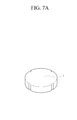
FIG. 7A is a top perspective view of a conventional ceramic diaphragm. -
FIG. 7B is a bottom perspective view of the conventional ceramic diaphragm. - Throughout the drawings and the detailed description, unless otherwise described, the same drawing reference numerals will be understood to refer to the same elements, features, and structures. The relative size and depiction of these elements may be exaggerated for clarity, illustration, and convenience.
- The following description is provided to assist the reader in gaining a comprehensive understanding of the methods, apparatuses, and/or systems described herein. Accordingly, various changes, modifications, and equivalents of the methods, apparatuses, and/or systems described herein will be suggested to those of ordinary skill in the art. Also, descriptions of well-known functions and constructions may be omitted for increased clarity and conciseness.
-
FIG. 1 is a perspective view of a pressure transducer using a ceramic diaphragm according to an exemplary embodiment of the present invention.FIG. 2 is a cross-sectional view of the pressure transducer taken along line A-A' ofFIG. 1 . Referring toFIGS. 1 and2 , the pressure transducer using a ceramic diaphragm includes aceramic diaphragm 10, abase plate 20 facing theceramic diaphragm 10, and anadhesive layer 40. The ceramic diaphragm is a rectangular planar ceramic diaphragm having a surface on which a pattern 50 (seeFIG. 4 ) made of an electrically conductive material andstrain gages 30 are formed. Thebase plate 20 faces the surface of the ceramic diaphragm on which thepattern 50 is formed, and theadhesive layer 40 is disposed along the edges of the facing surfaces of theceramic diaphragm 10 and thebase plate 20 to bond together theceramic diaphragm 10 and thebase plate 20 and to form a space for thestrain gages 30. - One of the most important characteristics of the pressure transducer according to the exemplary embodiment is that the
ceramic diaphragm 10 and thebase plate 20 are bonded by theadhesive layer 40 that is formed along the edges of theceramic diaphragm 10 and thebase plate 20. Theadhesive layer 40 may be first formed either on theceramic diaphragm 10 along the edges or on thebase plate 20 along the edges, and then one can be attached to the other. Alternatively, theceramic diaphragm 10 and thebase plate 20 may be arranged facing each other at a predetermined distance and be bonded together by theadhesive layer 40 disposed along the edges of the facingceramic diaphragm 10 and thebase plate 20. - Accordingly, there is no risk of damaging the
ceramic diaphragm 10 even when an excessive pressure is applied to the pressure transducer, and thus the leakage of a measurement target medium is prevented, and thereby the reliability and safety can be ensured. - More specifically, a conventional pressure transducer illustrated in
FIG. 6 has a limitation in reducing a gap G for a space between abase plate 3 andstrain gages 2 when mechanically manufacturing thebase plate 3. Accordingly, when an excessive pressure is applied to aceramic diaphragm 1, causing theceramic diaphragm 1 to be severely bent, theceramic diaphragm 10 may not be able to contact thebase plate 3 due to the wide gap G, and thereby being damaged. In a case where theceramic diaphragm 10 is damaged or broken, a measurement target medium may leak through a venting hole 4. On the contrary, the pressure transducer using the ceramic diaphragm in accordance with the exemplary embodiment of the present invention uses an adhesive, the thickness of which is easy to control, so that it is possible to form the gap G to be equal to or narrower than 10 µm. Hence, even when an excessive pressure is applied, theceramic diaphragm 10 is able to contact thebase plate 20, and thereby there is no risk of damaging theceramic diaphragm 10 and the measurement target medium is prevented from leaking. Accordingly, the safety and reliability of the pressure transducer can be ensured. - The thickness of the
adhesive layer 40 may desirably but not necessarily be smaller than 10 µm. In addition, various types of adhesive may be used for theadhesive layer 40 as long as the adhesive does not affect the effects of the present invention, and examples of the adhesive suitable for use may include low-melting glass and glass frit. - In addition, because the
ceramic diaphragm 10 and thebase plate 20 are bonded by theadhesive layer 40, manufacturing time and process can be far more reduced as compared to the conventional mechanical processes of manufacturing the base plate 3 (seeFIG. 6 ) to form the gap G for thestrain gages 2 or of manufacturing a ceramic diaphragm 1 (seeFIG. 5 ) for a pressure introducing portion. - Therefore, less cost is required for manufacturing the pressure transducer according to the exemplary embodiment of the present invention, when compared to the conventional pressure transducer, and thus it may have the advantage of low-cost production.
- Referring back to
FIG. 1 ,reference numeral 51 represents terminal solder pads, which are electrically connected to thepattern 50 formed on theceramic diaphragm 10. - Another important characteristic of the pressure transducer in accordance with the exemplary embodiment of the present invention is that only on a surface of the rectangular planar
ceramic diaphragm 10, thepattern 50 formed of the electrically conductive material and thestrain gages 30 are formed. For this configuration, a length l20 of thebase plate 20 is shorter than a length l10 of theceramic diaphragm 10 having the pattern formed thereon. That is, by configuring theceramic diaphragm 10 to be longer than thebase plate 20, theterminal solder pads 51 are disposed only on theceramic diaphragm 10 to electrically connect thestrain gages 20 and the pattern 60 formed of the electrically conductive material. - Conventionally, patterns are formed on both a ceramic diaphragm and a base plate and thereafter, the ceramic diaphragm and the base plate are connected to each other by conductive epoxy resin, whereas in the exemplary embodiment of the present invention, the pattern formed of an electrically conductive material is disposed only on the ceramic diaphragm and thus it is possible to manufacture the pressure transducer without forming the pattern on the base plate and without using conductive epoxy resin. As a result, the manufacturing process can be simplified, and thereby significantly reduce the manufacturing cost.
- Further, the shape of the
base plate 20 may be a rectangular plane that corresponds to the rectangular planarceramic diaphragm 10, and a thickness d20 of thebase plate 20 may be thicker than a thickness d10 of theceramic diaphragm 10. The length l10 of the rectangular planarceramic diaphragm 10 is longer than the length l20 of thebase plate 20. However, the difference between the lengths l10 and l20 may be only long enough for theterminal solder pads 51 to be formed as protruding from thebase plate 20 and to function normally. - In addition, the strain gages 30 may be formed by printing a paste layer of a conductive material, Au or Ag, and an electrical resistive material for forming the strain gage on the
ceramic diaphragm 10 by use of screen printing, and then patterning the resulting layer with the drying and sintering process. Various well-known patterning methods may also be used. - The pressure transducer converts a pressure into a resistance change of the strain gages 30, and it is important to convert the pressure into the effective change of the strain gages 30. In response to a uniform pressure being exerted on the
diaphragm 10 which has its outer surface fixed, a bent strain is imposed on the surface, and a small change which is applied to the back surface of thediaphragm 10 by the application of the pressure may cause a Wheatstone bridge consisting of fourstrain gages 30 to detect a small resistance change and to convert the detected small resistance change into an electrical signal. There are various patterns of strain gages to effectively detect a bent strain imposed on thediaphragm 10 that is fixed by the pressure. In the exemplary embodiment of the present invention, thestrain gages 30 are formed by printing a thick film resistor.FIG. 4 is a top view of an example of the ceramic diaphragm for the pressure transducer, having apattern 50 and fourstrain gages 30 formed thereon. Two of the strain gages 30 may be placed at a central portion of thediaphragm 10 that is most likely to be deformed in the central direction of a diaphragm circle 30-1 and the remaining twostrain gages 30 may be placed over the edges of the diaphragm circle 30-1 which are most likely to be deformed in the circumferential direction of the diaphragm circle 30-1. - In addition, the
diaphragm 10 is made of ceramic to electrically isolate thestrain gages 30 from thediaphragm 10. A resistance value of the strain gages 30 may be controlled between 100 Ω and 20 kΩ by adjusting a thickness of a thin film and lengths of thegages 30. -
FIG. 2 is a cross-sectional view of the pressure transducer taken along line A-A' ofFIG. 1 , andFIG. 3 is a cross-sectional view of a pressure transducer using a ceramic diaphragm according to another exemplary embodiment of the present invention. "P" and "P'" each represents a pressure introducing portion. - Although not illustrated in
FIGS. 2 and3 which depict the essential elements of the pressure transducer, a simplified flexible cable with a reduced volume is formed on a top of thebase plate 20 and a signal processing integrated circuit (IC) chip is mounted on the flexible cable. The signal processing IC chip may be an application specific integrated circuit (ASIC). Hence, the pressure transducer using a ceramic diaphragm enables to implement the small volume and a compact structure of the flexible cable and thereby to simplify the flexible cable, which contributes to the low price of the pressure transducer. - The pressure transducer using the ceramic diaphragm shown in
FIG. 2 is a transducer to measure a pressure with respect to an absolute vacuum. Generally, one portion of the diaphragm on which a pressure is applied is closed to form a reference vacuum chamber, and a pressure to be measured is introduced into the other portion. A degree of vacuum is an absolute reference for the transducer, and since it is not possible to adjust the absolute reference after the manufacturing, deterioration of the degree of vacuum due to leakage may cause the degradation of transducer performance. Thus, a leakage test or a vacuum-sealing process needs to be performed with great care. To this end, abase plate 20 having a plurality of lead lines (not shown) and theceramic diaphragm 10 having the strain gages 30 formed thereon are attached together by theadhesive layer 40 to air-tight seal the strain gages 30. - In addition, in
FIG. 3 , a gage pressure transducer as the pressure transducer using a ceramic diaphragm is to measure a gage pressure with reference to an ambient pressure, or a differential pressure transducer as the pressure transducer is to measure a difference between two pressures. For such measurement, a ventinggroove 21 is formed on the base plate. - In the exemplary embodiment of the present invention, the
ceramic diaphragm 10 and thebase plate 20 may be desirably, but not necessarily, a rectangular plane, so that mass production of the pressure transducer and reduction of manufacturing costs can be achieved. - More specifically, since a conventional pressure transducer has a circular ceramic diaphragm and a circular base plate as shown in
FIGS. 7A and7B , its massive production is very difficult, resulting in an increase in the price of the pressure transducer. In contrast, the pressure transducer using a ceramic diaphragm in accordance with the exemplary embodiment of the present invention includes the rectangular planar ceramic diaphragm and the rectangular planar base plate, and thus high mass production of the pressure transducer is feasible and thereby the price of the pressure transducer can be reduced. - As described above, it is possible to provide a pressure transducer using a ceramic diaphragm, which is not easily damaged so that there is no risk of leakage of a target medium to be measured, having a superior mass-production capability and a reduced volume and enabling low-price by simplifying a flexible cable and a printed circuit board (PCB) to connect the transducer and a signal processing chip.
- In addition, since a pattern formed of an electrically conductive material is disposed only on the ceramic diaphragm and thus it is possible to manufacture the pressure transducer without forming the pattern on the base plate and without using conductive epoxy resin. As a result, the manufacturing process can be simplified, and thereby significantly reduce the manufacturing cost.
- The pressure transducer using a ceramic diaphragm may be applicable to measure, for example, a pressure of a vehicle engine, and a wide range of pressure in various fields, such as industrial fields and civil engineering fields, which require a high level of precision in measurement.
- A number of examples have been described above. Nevertheless, it will be understood that various modifications may be made. For example, suitable results may be achieved if the described techniques are performed in a different order and/or if components in a described system, architecture, device, or circuit are combined in a different manner and/or replaced or supplemented by other components or their equivalents. Accordingly, other implementations are within the scope of the following claims.
Claims (4)
- A pressure transducer using a ceramic diaphragm, comprising:the ceramic diaphragm formed as a rectangular planar ceramic diaphragm and having a surface having formed thereon a pattern made of an electrically conductive material and strain gages;a base plate configured to face the surface of the ceramic diaphragm having formed thereon the pattern; andan adhesive layer configured to be formed along edges of a contacting surface of the ceramic diaphragm and the base plate so as to bond the ceramic diaphragm and the base plate and form a space for the strain gages.
- The pressure transducer of claim 1, wherein the base plate has a thickness thicker than a thickness of the ceramic diaphragm and has a length shorter than a length of the ceramic diaphragm.
- The pressure transducer of claim 1, wherein a thickness of the adhesive layer is smaller than 10 µm.
- The pressure transducer of claim 1, wherein the adhesive layer is made of low-melting glass.
Applications Claiming Priority (2)
| Application Number | Priority Date | Filing Date | Title |
|---|---|---|---|
| US13/648,624 US8943896B2 (en) | 2012-10-10 | 2012-10-10 | Pressure transducer using ceramic diaphragm |
| KR1020120114992A KR20140046356A (en) | 2012-10-10 | 2012-10-16 | Pressure transducer using ceramic diaphragm |
Publications (1)
| Publication Number | Publication Date |
|---|---|
| EP2720019A1 true EP2720019A1 (en) | 2014-04-16 |
Family
ID=49274543
Family Applications (1)
| Application Number | Title | Priority Date | Filing Date |
|---|---|---|---|
| EP13187201.2A Withdrawn EP2720019A1 (en) | 2012-10-10 | 2013-10-03 | Pressure transducer using ceramic diaphragm |
Country Status (2)
| Country | Link |
|---|---|
| EP (1) | EP2720019A1 (en) |
| CN (1) | CN103728066A (en) |
Families Citing this family (7)
| Publication number | Priority date | Publication date | Assignee | Title |
|---|---|---|---|---|
| CN107643132A (en) * | 2016-07-22 | 2018-01-30 | 上海域丰传感仪器有限公司 | One kind sealing pressure ceramic flat membrane pressure sensor |
| US20200209086A1 (en) * | 2017-04-07 | 2020-07-02 | Formosa Measurement Technology Inc. Ltd. | Differential Pressure Sensor and Fabrication Method Therefor |
| CN108444621A (en) * | 2018-05-28 | 2018-08-24 | 深圳研勤达科技有限公司 | A kind of ceramic resistance type pressure sensor |
| CN109029826A (en) * | 2018-08-27 | 2018-12-18 | 广州西博臣科技有限公司 | A kind of anti high overload bellow-type ceramic resistive type pressure sensor |
| CN112179310A (en) * | 2019-07-02 | 2021-01-05 | 中兴通讯股份有限公司 | Processing method and device for Printed Circuit Board (PCB) |
| CN113532704A (en) * | 2020-04-14 | 2021-10-22 | 联合汽车电子有限公司 | Pressure sensor |
| CN112563145A (en) * | 2020-11-26 | 2021-03-26 | 娄底市安地亚斯电子陶瓷有限公司 | Preparation method of ceramic circuit of automobile preparation pressure strain gauge |
Citations (6)
| Publication number | Priority date | Publication date | Assignee | Title |
|---|---|---|---|---|
| US4481497A (en) * | 1982-10-27 | 1984-11-06 | Kulite Semiconductor Products, Inc. | Transducer structures employing ceramic substrates and diaphragms |
| KR100240012B1 (en) | 1997-05-23 | 2000-01-15 | 박재범 | Diaphragm |
| KR20010105085A (en) | 2000-05-19 | 2001-11-28 | 김정희 | A method for fabricting pressure transducer using ceramic diaphragm |
| US20040040382A1 (en) * | 2000-07-20 | 2004-03-04 | Thomas Peterson | Sensor usable in ultra pure and highly corrosive environments |
| US20040200291A1 (en) * | 2003-04-11 | 2004-10-14 | Xunhu Dai | Multilayer ceramic pressure sensor |
| DE102010063065A1 (en) * | 2010-12-14 | 2012-06-14 | Endress + Hauser Gmbh + Co. Kg | Pressure sensor and method for its manufacture + |
Family Cites Families (4)
| Publication number | Priority date | Publication date | Assignee | Title |
|---|---|---|---|---|
| JPS6165126A (en) * | 1984-09-06 | 1986-04-03 | Copal Denshi Kk | Pressure sensor |
| JPH08240500A (en) * | 1995-03-01 | 1996-09-17 | Matsushita Electric Ind Co Ltd | Capacitance type pressure sensor and its manufacture |
| US5824909A (en) * | 1995-08-04 | 1998-10-20 | Ifm Electronic Gmbh | Pressure measuring sensor and apparatus having a seal between a housing and a pressure measuring cell |
| JPH10148591A (en) * | 1996-09-19 | 1998-06-02 | Fuji Koki Corp | Pressure detector |
-
2013
- 2013-10-03 EP EP13187201.2A patent/EP2720019A1/en not_active Withdrawn
- 2013-10-10 CN CN201310470719.7A patent/CN103728066A/en active Pending
Patent Citations (6)
| Publication number | Priority date | Publication date | Assignee | Title |
|---|---|---|---|---|
| US4481497A (en) * | 1982-10-27 | 1984-11-06 | Kulite Semiconductor Products, Inc. | Transducer structures employing ceramic substrates and diaphragms |
| KR100240012B1 (en) | 1997-05-23 | 2000-01-15 | 박재범 | Diaphragm |
| KR20010105085A (en) | 2000-05-19 | 2001-11-28 | 김정희 | A method for fabricting pressure transducer using ceramic diaphragm |
| US20040040382A1 (en) * | 2000-07-20 | 2004-03-04 | Thomas Peterson | Sensor usable in ultra pure and highly corrosive environments |
| US20040200291A1 (en) * | 2003-04-11 | 2004-10-14 | Xunhu Dai | Multilayer ceramic pressure sensor |
| DE102010063065A1 (en) * | 2010-12-14 | 2012-06-14 | Endress + Hauser Gmbh + Co. Kg | Pressure sensor and method for its manufacture + |
Also Published As
| Publication number | Publication date |
|---|---|
| CN103728066A (en) | 2014-04-16 |
Similar Documents
| Publication | Publication Date | Title |
|---|---|---|
| EP2720019A1 (en) | Pressure transducer using ceramic diaphragm | |
| US4388668A (en) | Capacitive pressure transducer | |
| EP1984718B1 (en) | Thick film technology based ultra high pressure sensor utilizing integral port and diaphragm construction | |
| US7832269B2 (en) | Packaging multiple measurands into a combinational sensor system using elastomeric seals | |
| US10473546B2 (en) | Hermetic pressure sensor having a bending part | |
| EP2270455B1 (en) | Force sensor apparatus | |
| US9541461B2 (en) | Ceramic pressure sensor and method for production thereof | |
| CN105466625B (en) | Physical amount measuring device | |
| KR101848226B1 (en) | An improved pressure sensor structure | |
| US10060815B2 (en) | Pressure sensor | |
| CN101356426A (en) | Low cost high-voltage sensor | |
| US7882744B2 (en) | Flat planner pressure transducer | |
| EP3658877B1 (en) | Ceramic pressure sensor | |
| CN115452235A (en) | Pressure sensor core and manufacturing method thereof | |
| KR20070096655A (en) | Micro pressure sensor | |
| US8943896B2 (en) | Pressure transducer using ceramic diaphragm | |
| WO2020228700A1 (en) | Sensor and sensor manufacturing method | |
| CN210089911U (en) | Pressure sensor | |
| JPH11326088A (en) | Pressure sensor and its manufacture | |
| CN213714430U (en) | Flow sensor with cantilever structure | |
| KR100330370B1 (en) | A method for fabricting pressure transducer using ceramic diaphragm | |
| CN110763393A (en) | Pressure sensor | |
| CN114112122B (en) | High-precision ceramic pressure sensor | |
| CN110793706A (en) | Pressure sensor manufacturing method | |
| KR20150031995A (en) | Pressure sensor apparatus |
Legal Events
| Date | Code | Title | Description |
|---|---|---|---|
| PUAI | Public reference made under article 153(3) epc to a published international application that has entered the european phase |
Free format text: ORIGINAL CODE: 0009012 |
|
| 17P | Request for examination filed |
Effective date: 20131004 |
|
| AK | Designated contracting states |
Kind code of ref document: A1 Designated state(s): AL AT BE BG CH CY CZ DE DK EE ES FI FR GB GR HR HU IE IS IT LI LT LU LV MC MK MT NL NO PL PT RO RS SE SI SK SM TR |
|
| AX | Request for extension of the european patent |
Extension state: BA ME |
|
| 17Q | First examination report despatched |
Effective date: 20140522 |
|
| GRAP | Despatch of communication of intention to grant a patent |
Free format text: ORIGINAL CODE: EPIDOSNIGR1 |
|
| INTG | Intention to grant announced |
Effective date: 20160511 |
|
| STAA | Information on the status of an ep patent application or granted ep patent |
Free format text: STATUS: THE APPLICATION IS DEEMED TO BE WITHDRAWN |
|
| 18D | Application deemed to be withdrawn |
Effective date: 20160922 |